JP5817543B2 - Spiral steel pipe cutting method - Google Patents
Spiral steel pipe cutting method Download PDFInfo
- Publication number
- JP5817543B2 JP5817543B2 JP2012006224A JP2012006224A JP5817543B2 JP 5817543 B2 JP5817543 B2 JP 5817543B2 JP 2012006224 A JP2012006224 A JP 2012006224A JP 2012006224 A JP2012006224 A JP 2012006224A JP 5817543 B2 JP5817543 B2 JP 5817543B2
- Authority
- JP
- Japan
- Prior art keywords
- steel pipe
- spiral
- spiral steel
- plasma torch
- cutting
- Prior art date
- Legal status (The legal status is an assumption and is not a legal conclusion. Google has not performed a legal analysis and makes no representation as to the accuracy of the status listed.)
- Expired - Fee Related
Links
Images



Landscapes
- Arc Welding In General (AREA)
Description
本発明は、スパイラル鋼管の切断方法に関する。 The present invention relates to a method for cutting a spiral steel pipe.
スパイラル鋼管を造管後、所定の長さに切断する際には、ガストーチあるいはプラズマトーチ等を備えた溶断装置によって行っている(例えば、特許文献1,2参照)。
また、近年では溶接技術の発展により、造管速度が向上し、これに伴い、切断速度を向上させることが可能な高電流のプラズマトーチが開発され、実用化されている。
When a spiral steel pipe is formed and then cut into a predetermined length, it is performed by a fusing device equipped with a gas torch or a plasma torch (for example, see Patent Documents 1 and 2).
In recent years, with the development of welding technology, the pipe making speed has been improved, and accordingly, a high-current plasma torch capable of improving the cutting speed has been developed and put into practical use.
しかし、鋼管を切断する場合、切断部から飛散した鋼の溶融金属(ドロス)が切断部とは反対側の鋼管内面に付着する問題がある。このように、溶融金属が鋼管内面に付着した場合は、鋼管を切断した後に、溶融金属の除去作業を行う必要があり、さらには、この除去作業に多大の工数を要していた。 However, when a steel pipe is cut, there is a problem that molten steel (dross) scattered from the cut portion adheres to the inner surface of the steel pipe opposite to the cut portion. As described above, when the molten metal adheres to the inner surface of the steel pipe, it is necessary to perform the removal work of the molten metal after cutting the steel pipe.
そこで、このような問題に対して、特許文献3には、鋼管を切断する際に、パイプを1回転では切断できないような早い速度で回転させ、1回転ごとにプラズマアークによる切断部のガウジング(溝掘)を繰り返し行うことで鋼管を切断する方法が開示されており、これにより、鋼管内壁面に付着する溶融飛沫の堆積物を減少させることができるとしている。
Therefore, in order to solve such a problem,
また、特許文献4には、切断トーチを鋼管進行方向の前方または後方に適宜の角度傾斜させ、飛散する溶融金属を、所望の位置(マーキング位置)を避けるような位置に付着させる技術が開示されている。
また、特許文献5には、鋼板の切断する際の開先加工において、2次ガスの旋回流により切断面の角度の調整範囲を増大させ、トーチを傾けることなしに、トーチを垂直にした状態で開先角度を調整する技術が開示されている。
Further, in
しかしながら、特許文献3の技術については、鋼管を切断する際に生じる溶融飛沫量を減少させる方法であって、溶融飛沫の鋼管内壁面への付着を防ぐものではない。つまり、後工程において、鋼管内壁面へ付着した溶融飛沫を除去する工程を設けることは必須であり、作業効率の向上や作業環境の改善としては不十分であった。
However, the technique of
また、特許文献4の技術においては、鋼管切断の際に生じた溶融金属の飛散方向を制御する方法であって、溶融金属の量は制御しておらず、溶融金属の付着位置を所望の位置よりずらすことが可能となっても、上記特許文献3と同様に、鋼管内壁面へ付着した溶融金属を除去する工程を後工程にて設ける必要があった。
Moreover, in the technique of
また、特許文献5の技術においては、2次ガスの旋回流を制御することにより、トーチを傾けることなしに開先加工を可能としているものの、ドロス(溶融金属)の排出量については鋼管やトーチのキャップへの付着を低減できるとの記載に留まっており、溶融金属の鋼管内面への付着を抑制する精度としては不安定なものであった。
Further, in the technique of
また、従来では、鋼管を切断する際に生じる溶融金属の鋼管内面への付着を防止するために、鋼管内部に溶融金属用受け板(以下、単に受け板という)を配置し、該受け板に溶融金属を付着させるような措置を取っていた。
以下、受け板を用いた従来の鋼管切断方法について説明する。
Conventionally, in order to prevent the molten metal from adhering to the inner surface of the steel pipe that occurs when the steel pipe is cut, a molten metal backing plate (hereinafter simply referred to as a backing plate) is disposed inside the steel pipe, Measures were taken to attach molten metal.
Hereinafter, a conventional steel pipe cutting method using a backing plate will be described.
図5に、従来の鋼管の切断工程を示す。なお、図5は、鋼管切断位置における概略正面図である。
図5に示すように、従来の切断方法では、鋼管103の横方向からプラズマアークを発生させて鋼管を切断するようトーチ104を配置していた。つまり、トーチ104を搭載するとともに、鋼管103の進行方向と同一方向に走行する台車105の上面と略平行となるようトーチ104を配置していた。
また、従来の受け板109は鋼管103の内部に配置されているが、この受け板109は、回転方向を図中の矢印方向とする造管時の回転と、受け板の自重の影響により、鋼管底部から、トーチの配置位置と反対側の鋼管側面(水平位置)までを可動域として揺動している。すなわち、受け板109は、鋼管103の回転に同調して水平位置まで引き上げられるが、自重により鋼管底部にすべり落ちる。この動作を上記可動域内にて繰り返している。
FIG. 5 shows a conventional steel pipe cutting process. FIG. 5 is a schematic front view at the steel pipe cutting position.
As shown in FIG. 5, in the conventional cutting method, the
In addition, the conventional receiving
また、従来の切断方法では、図5に示すように、鋼管103の横方向からプラズマを発生させて鋼管103を切断させていたため、切断の際に発生した溶融金属は、トーチの配置位置とは反対側の鋼管内面(水平位置)に向けて飛散し付着していた。そのため、受け板109が水平位置に偏在している際は、溶融金属が鋼管に付着することなく受け板109に堆積させることができるが、受け板109が自重により鋼管底部にすべり落ちた際は、溶融金属が鋼管103に付着してしまう問題があった。
つまり、図5に示すような従来の方法では、溶融金属の飛散方向は水平方向と限定的であるが、受け板109が、造管時の回転とあて板109の自重の影響により揺動し、一定箇所に留まらないため、溶融金属を確実に受け板に付着させることは困難であり、溶融金属の鋼管103内面への付着を防止する精度が不安定であった。
Further, in the conventional cutting method, as shown in FIG. 5, since the
That is, in the conventional method as shown in FIG. 5, the scattering direction of the molten metal is limited to the horizontal direction, but the
また、従来の切断方法として図5に示すように、鋼管103を横方向(水平方向)より切断するよう、トーチを配置する例を示したが、従来の切断方法の他の例として、トーチを台車とは反対側の鋼管の上部に配置し、鋼管の上方向からプラズマを発生させて鋼管を切断する方法もある。しかしながら、この場合も同様に、受け板が造管時の回転と、受け板の自重の影響により揺動するため、受け板が水平位置に偏在している際は、溶融金属は鋼管に付着してしまう問題があった。
In addition, as shown in FIG. 5 as a conventional cutting method, an example in which a torch is arranged so as to cut the
本発明は、上記の実情に鑑みてなされたものであって、スパイラル鋼管内面に受け板を配置し、この受け板に対して反対側の鋼管外側にプラズマトーチを配置するとともに、受け板の揺動軌道に合わせてプラズマトーチの動作を制御して鋼管の切断方向を調整することにより、切断により生じた溶融金属の飛散方向を制御し、常に受け板に向けて溶融金属を飛散させて、鋼管内面への溶融金属の付着を防ぐことが可能となるスパイラル鋼管の切断方法を提供することを目的とする。 The present invention has been made in view of the above situation, and a receiving plate is arranged on the inner surface of a spiral steel pipe, a plasma torch is arranged on the outer side of the steel pipe opposite to the receiving plate, and the shaking of the receiving plate is also performed. By adjusting the cutting direction of the steel pipe by controlling the operation of the plasma torch according to the moving trajectory, the direction of the molten metal scattered by the cutting is controlled, and the molten metal is always scattered toward the backing plate. An object of the present invention is to provide a method of cutting a spiral steel pipe that can prevent adhesion of molten metal to the inner surface.
上記課題を解決することを目的とした本発明の要旨は、以下のとおりである。 The gist of the present invention aimed at solving the above problems is as follows.
[1]鋼帯をらせん状に巻きつつ前記鋼帯の幅方向端部同士を溶接することによりスパイラル鋼管を造管しながら、所定の長さに切断するスパイラル鋼管の切断方法において、回転する前記スパイラル鋼管の内部に、前記スパイラル鋼管に対して摺動可能に受け板を配置し、前記受け板に対して反対側の鋼管外側に配置したプラズマトーチによって前記スパイラル鋼管を切断する際、前記スパイラル鋼管の回転および自重によって揺動する前記受け板の揺動パターンに同調するように前記プラズマトーチのトーチ角度を調整することにより、前記プラズマトーチの動作を制御して切断方向を調整することを特徴とするスパイラル鋼管の切断方法。
[2]前記プラズマトーチの動作を制御する際、前記スパイラル鋼管の回転速度、前記スパイラル鋼管の径、前記受け板の前記径方向における幅、及び前記受け板の揺動周期によって前記受け板の揺動パターンを算出し、この算出した揺動パターンに同調するように前記プラズマトーチの動作を制御することを特徴とする上記[1]に記載のスパイラル鋼管の切断方法。
[3]前記揺動パターンに同調するよう前記プラズマトーチの動作を制御する際、前記プラズマトーチを回動可能に支持するよう前記プラズマトーチの鋼管とは反対側の端部に連結されたトーチ架台を上昇または下降させることにより、前記プラズマトーチの鋼管側端部を支点として前記プラズマトーチを回動させることを特徴とする上記[1]または[2]に記載のスパイラル鋼管の切断方法。
[4]前記スパイラル鋼管を切断するごとに、前記スパイラル鋼管の内部に配置した前記受け板の位置を検出し、この検出結果に基づき前記受け板の揺動パターンを修正して前記プラズマトーチを再配置することを特徴とする上記[1]〜[3]の何れか一項に記載のスパイラル鋼管の切断方法。
[5]切断の対象となる前記スパイラル鋼管の底面の高さ位置は、前記スパイラル鋼管の径によらず常に一定位置であることを特徴とする上記[1]〜[4]の何れか一項に記載のスパイラル鋼管の切断方法。
[1] In the spiral steel pipe cutting method, the spiral steel pipe is cut into a predetermined length while forming the spiral steel pipe by welding the widthwise ends of the steel band while winding the steel band in a spiral shape. In the spiral steel pipe, a receiving plate is disposed so as to be slidable with respect to the spiral steel pipe, and the spiral steel pipe is cut when the spiral steel pipe is cut by a plasma torch arranged on the outer side of the steel pipe opposite to the receiving plate. And adjusting the cutting direction by controlling the operation of the plasma torch by adjusting the torch angle of the plasma torch so as to synchronize with the swing pattern of the backing plate that swings due to its rotation and its own weight. To cut spiral steel pipe .
[2 ] When controlling the operation of the plasma torch, the swinging of the backing plate depends on the rotational speed of the spiral steel tube, the diameter of the spiral steel tube, the width of the backing plate in the radial direction, and the swinging cycle of the backing plate. The method for cutting a spiral steel pipe according to the above [ 1 ], wherein a motion pattern is calculated and the operation of the plasma torch is controlled so as to synchronize with the calculated swing pattern.
[ 3 ] When controlling the operation of the plasma torch so as to synchronize with the swing pattern, a torch mount connected to the end of the plasma torch opposite to the steel pipe so as to rotatably support the plasma torch. The method of cutting a spiral steel pipe according to the above [ 1 ] or [ 2 ], wherein the plasma torch is rotated with the steel pipe side end of the plasma torch as a fulcrum by raising or lowering.
[ 4 ] Every time the spiral steel pipe is cut, the position of the backing plate disposed inside the spiral steel pipe is detected, and based on the detection result, the swinging pattern of the backing plate is corrected, and the plasma torch is restarted. The method for cutting a spiral steel pipe according to any one of the above [ 1 ] to [ 3 ], wherein the method is arranged.
[ 5 ] Any one of the above [1] to [ 4 ], wherein the height position of the bottom surface of the spiral steel pipe to be cut is always a constant position regardless of the diameter of the spiral steel pipe. A method for cutting a spiral steel pipe according to claim 1.
本発明のスパイラル鋼管の切断方法によれば、スパイラル鋼管内面に受け板を配置し、この受け板に対して反対側の鋼管外側にプラズマトーチを配置するとともに、受け板の揺動パターンに合わせてプラズマトーチの動作を制御して鋼管の切断方向を調整することにより、切断により生じた溶融金属の飛散方向を制御し、常に受け板に向けて溶融金属を飛散させて、鋼管内面への溶融金属の付着を防ぐことが可能となる。 According to the method for cutting a spiral steel pipe of the present invention, a receiving plate is arranged on the inner surface of the spiral steel pipe, a plasma torch is arranged on the outer side of the steel pipe opposite to the receiving plate, and in accordance with the swing pattern of the receiving plate. By controlling the cutting direction of the steel pipe by controlling the operation of the plasma torch, the direction of the molten metal scattered by the cutting is controlled, and the molten metal is always scattered toward the receiving plate, so that the molten metal on the inner surface of the steel pipe Can be prevented.
また、スパイラル鋼管の切断工程の後工程において、鋼管内部に付着した溶融金属の除去工程を省略することができるため、製造効率の向上、および溶融金属除去作業者の重負荷作業の解消により作業環境の改善ができる。 In addition, the process of removing the molten metal adhering to the inside of the steel pipe can be omitted in the subsequent process of the cutting process of the spiral steel pipe, thereby improving the manufacturing efficiency and eliminating the heavy load work of the molten metal removing operator. Can be improved.
以下、本実施形態のスパイラル鋼管の切断方法について詳細に説明する。 Hereinafter, the cutting method of the spiral steel pipe of this embodiment is demonstrated in detail.
本実施形態のスパイラル鋼管の切断方法は、鋼帯をらせん状に巻きつつ前記鋼帯の幅方向端部同士を溶接することにより、スパイラル鋼管を造管しながら所定の長さに切断するスパイラル鋼管の切断方法において、回転するスパイラル鋼管の内部に、スパイラル鋼管に対して摺動可能に受け板を配置し、受け板に対して反対側の鋼管外側に配置したプラズマトーチによってスパイラル鋼管を切断する際、スパイラル鋼管の回転および自重によって揺動する受け板の揺動パターンに同調するようにプラズマトーチのトーチ角度を調整することにより、プラズマトーチの動作を制御して切断方向を調整する方法である。
以下、溶融金属の鋼管内面への付着を防止するために重要となる受け板の配置、及びプラズマトーチの配置位置について、図を参照しながら詳細に説明する。
The spiral steel pipe cutting method of this embodiment is a spiral steel pipe that is cut into a predetermined length while forming a spiral steel pipe by welding the widthwise ends of the steel band while winding the steel band in a spiral shape. in the process of cutting, the interior of the spiral pipe to be rotated, when cutting the spiral pipe with the slidably receiving plate disposed relative to the spiral pipe, receiving a plasma torch disposed in the steel outside the opposite side of the plate This is a method of adjusting the cutting direction by controlling the operation of the plasma torch by adjusting the torch angle of the plasma torch so as to synchronize with the swing pattern of the receiving plate that swings by the rotation of the spiral steel tube and its own weight .
Hereinafter, the arrangement of the backing plate and the arrangement position of the plasma torch which are important for preventing the molten metal from adhering to the inner surface of the steel pipe will be described in detail with reference to the drawings.
まず、本実施形態のスパイラル鋼管を切断するために用いる切断装置について説明する。
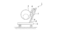
図1に、本実施形態のおけるスパイラル鋼管の切断工程を示す概略図であって、鋼管切断位置における正面図である。
本実施形態におけるスパイラル鋼管の切断装置1は、図1に示すように、軸方向に移動するスパイラル鋼管3に合わせて移動する走行台車5と、この走行台車5の上に搭載されるとともに、走行台車5の上面と所定の角度を有して延在する斜行アーム6と、斜行アーム6に可動支持され、上昇・下降動作が可能なトーチ架台7と、トーチ架台7の上端部に連結されたプラズマトーチ4とから概略構成されており、プラズマトーチ4が連結されたトーチ架台7を斜行アーム6上を滑走させることにより、プラズマトーチ4の高さ位置を調整できるようになっている。
なお、プラズマトーチ4の鋼管とは反対側の端部がトーチ架台7の上端部に連結されており、この連結部は回動可能となっている。
First, the cutting device used in order to cut | disconnect the spiral steel pipe of this embodiment is demonstrated.
FIG. 1 is a schematic view showing a spiral steel pipe cutting process in the present embodiment, and is a front view at a steel pipe cutting position.
As shown in FIG. 1, the spiral steel pipe cutting device 1 according to the present embodiment is mounted on the traveling
In addition, the edge part on the opposite side to the steel pipe of the
本実施形態では上述した切断装置1を用いてスパイラル鋼管3を切断するが、図2に示すように、回転するスパイラル鋼管3の内部に、スパイラル鋼管3に対して摺動可能な受け板9を配置した状態で、鋼管を切断する。
なお、本実施形態では図3に示すような造管装置10を用いて、鋼帯2を矢印A方向に進行させながららせん状に巻きつつ、鋼帯2の幅方向端部同士を溶接原点8にて溶接することにより、スパイラル鋼管3を造管するが、このとき受け板9は、造管装置10と連結部材20により連結されて配置される。このときの連結部材20の長さ、つまり受け板9の造管装置10からの距離は、用いる造管装置、切断装置、作業環境、切断するスパイラル鋼管の長さ等により適宜決定してよい。また、連結部材20としては、例えば、鋼製の鎖(チェーン)を用いるとよい。
In this embodiment, the
In the present embodiment, a
上述したように、受け板9は、スパイラル鋼管3に対して摺動可能に配置するため、受け板9は、回転方向を図1中の矢印方向とする造管時の回転と自重の影響を受ける。そのため、図2に示すように、スパイラル鋼管3の底部からプラズマトーチ4の配置位置と反対側のスパイラル鋼管3側面(水平位置)までを可動域として揺動する。
そのため、本実施形態においては、図2に示すように、受け板9に対して反対側のスパイラル鋼管3の外側にプラズマトーチ4を配置し、スパイラル鋼管3に対して斜方向からプラズマアークを発生させて切断する。
このように、受け板9の揺動を考慮して、スパイラル鋼管3に対して斜方向から切断するようプラズマトーチ4を配置することにより、切断により生じる溶融金属を受け板9に向けて飛散させることができる。その結果、スパイラル鋼管3の内面への溶融金属の付着を防ぐことできる。
なお、図2は受け板9の配置とプラズマトーチ4の配置位置について説明するための図であり、他の部材の図示を省略している。
As described above, since the receiving
Therefore, in this embodiment, as shown in FIG. 2, the
In this way, in consideration of the swing of the receiving
FIG. 2 is a diagram for explaining the arrangement of the receiving
また、本実施形態において、スパイラル鋼管3に対して45°の方向からプラズマアークを発生させて切断することが好ましい。
本発明者らによると、受け板9は上述したような可動域内において揺動しているが、受け板9の幅と可動域の範囲とから受け板9とスパイラル鋼管3との相対的位置を導出してみると、水平位置と鋼管底部との中間に常に存在していることが分かった。すなわち、受け板9は揺動してはいるが、スパイラル鋼管3の内側面のうち、底部を原点とした場合に造管方向に45°の位置に常に位置している。そのため、プラズマトーチ4の向き(プラズマアークの照射方向)をスパイラル鋼管3に対して45°とすることにより、切断により発生する溶融金属を、受け板9に対して安定して付着させることができる。
Further, in the present embodiment, it is preferable that the
According to the present inventors, the receiving
また、本実施形態では、上述したような受け板9の揺動する軌道(揺動パターン)に同調するようにプラズマトーチ4の動作を制御して鋼管の切断方向を調整してもよい。
図2に示すように、受け板9は、造管時の回転に同調して水平位置まで引き上げられるが、ある一定の水平位置まで引き上げられると、自重によりスパイラル鋼管3の底部にすべり落ちる。即ち、受け板9の鋼管内での動きは、これらの動作を上記可動域内にて繰り返すような図2中に示す矢印B方向の揺動パターンを有する動きであり、この揺動パターンに同調するようにプラズマトーチ4の動作を制御する。つまり、常にプラズマトーチ4の先端が受け板9と対向するよう、揺動パターンに合わせてプラズマトーチ4の動作を調節する。
In the present embodiment, the cutting direction of the steel pipe may be adjusted by controlling the operation of the
As shown in FIG. 2, the receiving
具体的に説明すると、図2に示すように、受け板9が水平位置まで引き上げられた場合は、プラズマトーチ4とトーチ架台7とのなす角度α(以下、トーチ角度αという)を大きくし、一方、受け板9が自重によりスパイラル鋼管3の底部にすべり落ちた場合は、トーチ角度αを小さくし、常にプラズマトーチ4の先端と受け板9とが対向するよう制御する。これにより、切断方向が常に受け板9の方向を向くため、切断により生じる溶融金属を、より正確に受け板9に向けて飛散させることができる。
Specifically, as shown in FIG. 2, when the receiving
また、本実施形態において、プラズマトーチ4の動作を制御する際、スパイラル鋼管3の回転速度V、スパイラル鋼管3の径R、受け板9の径方向における幅W、及び受け板9の揺動周期Tによって、上述したような受け板9の揺動パターンを算出し、この算出した揺動パターンに同調するようにプラズマトーチ4の動作を制御することが好ましい。
以下、揺動パターンの算出方法について説明する。
In this embodiment, when controlling the operation of the
Hereinafter, a calculation method of the swing pattern will be described.
径がRであるスパイラル鋼管3の内部に配置した受け板9の動き(揺動)は、スパイラル鋼管3の回転速度V、径R、受け板9の幅W、そして受け板9の揺動周期Tに大きく依存し、これらによってスパイラル鋼管3の底部からスパイラル鋼管3側面(水平位置)までにおいて受け板9の揺動する可動域が決定され、回転するスパイラル鋼管3の内部における受け板9の揺動パターンを算出することができる。
The movement (swing) of the
揺動パターンを算出するためには、例えばまず、鋼帯の送り速度(溶接速度)と径Rとからスパイラル鋼管の回転速度Vを予め計算しておくとともに、この回転速度V、径R、受け板の幅Wに基づき揺動周期Tを算出し、これらを纏めた操業データを作成しておくとよい。そして、このような操業データに基づき、受け板の動きを推定してパターン化することにより揺動パターンを算出することができる。そして、得られた揺動パターンに基づいてプラズマトーチ4の動作を制御する。
このように、予め受け板の揺動パターンを推定し、この揺動パターンに同調するようにトーチ角度を調整してプラズマトーチの動作を制御することにより、プラズマトーチの向きを常に受け板方向に向かせることができるため、より正確に、溶融金属を受け板に向けて飛散させることができる。そのため、スパイラル鋼管への溶融金属の付着をより確実に防止することができる。
In order to calculate the swing pattern, for example, first, the rotational speed V of the spiral steel pipe is calculated in advance from the feed speed (welding speed) of the steel strip and the diameter R, and the rotational speed V, diameter R, It is preferable to calculate the swing period T based on the width W of the plate and create operation data in which these are summarized. And based on such operation data, a rocking | fluctuation pattern can be calculated by estimating and patterning a motion of a backing plate. The operation of the
Thus, by presuming the swing pattern of the backing plate in advance and adjusting the torch angle so as to synchronize with this swing pattern and controlling the operation of the plasma torch, the orientation of the plasma torch is always in the direction of the backing plate. Therefore, the molten metal can be scattered more accurately toward the receiving plate. Therefore, adhesion of the molten metal to the spiral steel pipe can be prevented more reliably.
また、本実施形態においては、上述したように、揺動パターンに同調するようプラズマトーチ4の動作を制御する際、トーチ架台7を上昇または下降させることにより、プラズマトーチ4の鋼管側端部4aを支点としてプラズマトーチ4を回動させてトーチ角度αを調整し、プラズマトーチ4の動作を制御してもよい。
本実施形態に係るプラズマトーチ4は、プラズマトーチ4の鋼管とは反対側の端部において、トーチ架台7に回動可能に支持されている。そのため、トーチ架台7を上昇または下降させることにより、プラズマトーチ4の鋼管側端部4aを支点としてプラズマトーチ4を回動させてプラズマトーチ4のトーチ角度αを調整することができる。
In the present embodiment, as described above, when controlling the operation of the
The
例えば、受け板9がスパイラル鋼管3の回転により水平位置まで引き上げられた際は、その揺動に同調するようプラズマトーチ4の動作を制御するが、その際は、トーチ角度αを大きくするようトーチ架台7を下降させて、プラズマトーチ4の鋼管側端部4aを支点としてプラズマトーチ4を回動させればよい。また、受け板9がその自重によりスパイラル鋼管3の底部まですべり落ちた際は、トーチ角度αを小さくするようトーチ架台7を上昇させて、プラズマトーチ4を回動させればよい。
このように、本実施形態のようにトーチ架台7を上昇または下降させることのみでトーチ角度を調整することができるため、プラズマトーチ4の動作を制御するための別途新たな制御装置を設ける必要なく、プラズマトーチ4の動作を制御することができる。
For example, when the receiving
Thus, since the torch angle can be adjusted only by raising or lowering the
また、プラズマトーチ4のトーチ角度αを調整してプラズマトーチ4の動作を制御する際、プラズマトーチ4の鋼管側端部4aを支点として回動させるため、トーチ角度αを調整して切断方向を変更したとしても、スパイラル鋼管3とプラズマトーチの鋼管側端部4aとの距離を一定に保持できる。そのため、切断面の品質への影響は少なく、スパイラル鋼管としての品質を確保することができる。
Further, when the operation of the
また、本実施形態では、鋼帯2をらせん状に巻きつつ鋼帯2の幅方向端部同士を溶接することによりスパイラル鋼管3を造管しながら切断するが、スパイラル鋼管3を切断するごとに、スパイラル鋼管3の内部に配置した受け板9の位置を検出し、この検出結果に基づき受け板9の揺動パターンを修正し、プラズマトーチ4を再配置することが好ましい。
上述したように、受け板9の揺動パターンを予め算出しておき、この揺動パターンに同調するようにプラズマトーチ4の動作を制御して、溶融金属の飛散方向を調整するが、スパイラル鋼管3を切断するごとに、実際の受け板9の位置を検出し、この検出結果に基づいて受け板9の揺動パターンを修正し、この修正した揺動パターンに基づいてプラズマトーチ4のトーチ角度αを再調整し、プラズマトーチ4を再配置することが好ましい。
また、操業トラブル等により、鋼帯2の走行やスパイラル鋼管3の回転が停止してしまった場合も同様に、受け板9の位置を検出し、揺動パターンを修正し、プラズマトーチ4を再配置することが好ましい。
このように、受け板9の実際の位置を検出し、この検出結果に基づいて揺動パターンを修正することにより、より正確にプラズマトーチ4を受け板9の揺動パターンに同調させることができるため、溶融金属を受け板9へ付着させる精度を向上させることができる。つまり、スパイラル鋼管3内部への溶融金属の付着をより防ぐことができる。
In the present embodiment, the
As described above, the swing pattern of the receiving
Similarly, when the travel of the
Thus, by detecting the actual position of the receiving
また、本実施形態では、切断の対象となるスパイラル鋼管3の底面の高さ位置は、スパイラル鋼管3の径Rによらず常に一定位置としてもよい。
図4に示すように、上述したような切断装置1を用いた場合、斜行アーム6に沿ってトーチ架台7を走行させることにより、異なる径を有する種々のスパイラル鋼管の切断にも容易に対応させることができる。つまり、スパイラル鋼管の底面の土台5からの高さ位置を変更することなく一定に保持したまま、トーチ架台7の走行を制御することのみで、異なる径を有する種々のスパイラル鋼管の切断を行うことができる。
In the present embodiment, the height position of the bottom surface of the
As shown in FIG. 4, when the cutting device 1 as described above is used, it is possible to easily cut various spiral steel pipes having different diameters by running the
また、本実施形態において、土台5と斜行アーム6とのなす角度β(アーム角度β)は特に限定しないが、本発明者らの知見によると、67.5°とすることが好ましい。
アーム角度は切断に用いる装置によって適宜変更してもよいが、上述したような切断装置を用いて切断する場合、アーム角度βを67.5°とすることにより、受け板に対するプラズマトーチの位置、つまりトーチ角度αを好適なものすることができ、溶融金属の鋼管内面への付着をより防ぐことができる。
In the present embodiment, the angle β (arm angle β) formed between the
The arm angle may be appropriately changed depending on the device used for cutting. However, when cutting using the above-described cutting device, the arm angle β is set to 67.5 °, thereby the position of the plasma torch with respect to the backing plate, That is, the torch angle α can be made suitable, and adhesion of molten metal to the inner surface of the steel pipe can be further prevented.
また、本実施形態にかかる受け板9の形状は特に限定しないが、平面視略矩形の板状のものであればよい。また、本実施形態においては、スパイラル鋼管3の内部に配置する際、スパイラル鋼管3に対して摺動可能に配置するため、受け板9の断面形状は波状のものを用いることが好ましい。
Moreover, the shape of the receiving
以上説明したような本発明に係るスパイラル鋼管の切断方法によれば、スパイラル鋼管内部に配置した受け板に対して反対側の鋼管外側にプラズマトーチを配置した上で切断するため、切断方向をより正確に受け板に向けることができ、そのため、溶融金属の鋼管内面への付着を防止することができる。 According to the method for cutting a spiral steel pipe according to the present invention as described above, since the plasma torch is arranged outside the steel pipe opposite to the receiving plate arranged inside the spiral steel pipe, the cutting direction is further changed. It can be accurately directed to the backing plate, and therefore, adhesion of molten metal to the inner surface of the steel pipe can be prevented.
また、スパイラル鋼管の回転および自重によって揺動する受け板の揺動軌道に同調するように、トーチ角度を調整してプラズマトーチの動作を制御するので、プラズマトーチの向きをより正確に受け板に向けることができる。その結果、溶融金属の内面への付着をより防止することができる。 In addition, the torch angle is adjusted to control the operation of the plasma torch so that it synchronizes with the swinging trajectory of the backing plate that swings due to the rotation of the spiral steel tube and its own weight. Can be directed. As a result, adhesion of the molten metal to the inner surface can be further prevented.
1・・・切断装置
2・・・鋼帯
3・・・スパイラル鋼管
4・・・プラズマトーチ
4a・・・プラズマトーチの鋼管側端部
5・・・走行台車
6・・・斜行アーム
7・・・トーチ架台
8・・・溶接原点
9・・・受け板
10・・・造管装置
20・・・連結部材
α・・・トーチ角度
β・・・アーム角度
DESCRIPTION OF SYMBOLS 1 ... Cutting
Claims (5)
回転する前記スパイラル鋼管の内部に、前記スパイラル鋼管に対して摺動可能に受け板を配置し、
前記受け板に対して反対側の鋼管外側に配置したプラズマトーチによって前記スパイラル鋼管を切断する際、前記スパイラル鋼管の回転および自重によって揺動する前記受け板の揺動パターンに同調するように前記プラズマトーチのトーチ角度を調整することにより、前記プラズマトーチの動作を制御して切断方向を調整することを特徴とするスパイラル鋼管の切断方法。 In the spiral steel pipe cutting method of cutting to a predetermined length while forming a spiral steel pipe by welding the widthwise ends of the steel band while winding the steel band in a spiral shape,
Inside the rotating spiral steel pipe, a receiving plate is disposed so as to be slidable with respect to the spiral steel pipe,
When the spiral steel pipe is cut by a plasma torch disposed on the outer side of the steel pipe opposite to the backing plate, the plasma is synchronized with the swinging pattern of the backing plate that swings due to the rotation and weight of the spiral steel pipe. A method for cutting a spiral steel pipe , wherein the cutting direction is adjusted by controlling the operation of the plasma torch by adjusting the torch angle of the torch .
Priority Applications (1)
| Application Number | Priority Date | Filing Date | Title |
|---|---|---|---|
| JP2012006224A JP5817543B2 (en) | 2012-01-16 | 2012-01-16 | Spiral steel pipe cutting method |
Applications Claiming Priority (1)
| Application Number | Priority Date | Filing Date | Title |
|---|---|---|---|
| JP2012006224A JP5817543B2 (en) | 2012-01-16 | 2012-01-16 | Spiral steel pipe cutting method |
Publications (2)
| Publication Number | Publication Date |
|---|---|
| JP2013144307A JP2013144307A (en) | 2013-07-25 |
| JP5817543B2 true JP5817543B2 (en) | 2015-11-18 |
Family
ID=49040436
Family Applications (1)
| Application Number | Title | Priority Date | Filing Date |
|---|---|---|---|
| JP2012006224A Expired - Fee Related JP5817543B2 (en) | 2012-01-16 | 2012-01-16 | Spiral steel pipe cutting method |
Country Status (1)
| Country | Link |
|---|---|
| JP (1) | JP5817543B2 (en) |
Families Citing this family (1)
| Publication number | Priority date | Publication date | Assignee | Title |
|---|---|---|---|---|
| CN103722285B (en) * | 2013-12-30 | 2016-04-13 | 太原重工股份有限公司 | Round pipe cutting device |
Family Cites Families (5)
| Publication number | Priority date | Publication date | Assignee | Title |
|---|---|---|---|---|
| JPS52153845A (en) * | 1976-06-16 | 1977-12-21 | Kubota Ltd | Device for deleting adhesion of tube cutting dross |
| JPS60126375U (en) * | 1984-02-03 | 1985-08-26 | 昭和電線電纜株式会社 | Roller storage member |
| JPH07284944A (en) * | 1994-04-15 | 1995-10-31 | Sango Co Ltd | Spatter scattering prevention device of arc welding machine |
| JP2945611B2 (en) * | 1995-06-23 | 1999-09-06 | トーヨーカネツ株式会社 | Welding method |
| JP2001150135A (en) * | 1999-11-24 | 2001-06-05 | Nippon Steel Corp | Spiral steel pipe cutting method and cutting device |
-
2012
- 2012-01-16 JP JP2012006224A patent/JP5817543B2/en not_active Expired - Fee Related
Also Published As
| Publication number | Publication date |
|---|---|
| JP2013144307A (en) | 2013-07-25 |
Similar Documents
| Publication | Publication Date | Title |
|---|---|---|
| JP6479793B2 (en) | Method and system for plasma cutting holes and contours in a workpiece | |
| KR101067998B1 (en) | Plasma Automatic Welding Device for Pipe Circumferential Welding | |
| EP2177301A1 (en) | Welding equipment and welding method | |
| CN104708220B (en) | A kind of pipeline all-position working rig and its control method | |
| KR20110038073A (en) | Method for obliquely cutting by eccentrically aligning the laser cutting beam with respect to the nozzle axis, the corresponding laser processing head and laser processing machine | |
| JP4457804B2 (en) | Spiral steel pipe outer surface bead cutting device and spiral steel pipe manufacturing device | |
| KR20120001528A (en) | Laser-arc hybrid welding device | |
| JP2015167984A (en) | Overlay welding system | |
| KR100994986B1 (en) | Pipe welding device and method thereof | |
| KR101509107B1 (en) | An apparatus for longitudinally welding a polygon metal pipe made of metal plate | |
| JP2013144307A (en) | Method for cutting spiral steel pipe | |
| JP5820249B2 (en) | Plasma arc welding method and plasma arc welding apparatus | |
| KR101289658B1 (en) | Wire saw machine for slicing ingot | |
| CN107000093A (en) | Build-up welding apparatus | |
| CN103769719A (en) | Automatic welding device and method for rear goosey beams of container | |
| JP2014521521A (en) | Air carbon arc system, apparatus and method of using the same for detecting and / or reducing irregularities on the workpiece surface | |
| KR101429604B1 (en) | welding apparatus for spherical surface | |
| KR101367009B1 (en) | A Welding System | |
| CN205166146U (en) | Unsteady tracking means of large aperture compound steel pipes plasma groove cutting | |
| KR101492143B1 (en) | High speed vibration device of welding wire adjustable vibrating amplitude and frequency | |
| KR20130051641A (en) | Auto-welding robot with 6 driving axis for angle overlap piece | |
| TWI696513B (en) | Machine for the laser working of profiles and method for carrying out an inclined cutting operation on a profile by means of this machine | |
| JP6792196B2 (en) | Welding equipment and welding method | |
| US20070095433A1 (en) | Method and apparatus for treating cracks in slabs | |
| CN103769732B (en) | Based on the large gauge angle-steel blanking method of numerical control cutting machine |
Legal Events
| Date | Code | Title | Description |
|---|---|---|---|
| A621 | Written request for application examination |
Free format text: JAPANESE INTERMEDIATE CODE: A621 Effective date: 20140212 |
|
| A977 | Report on retrieval |
Free format text: JAPANESE INTERMEDIATE CODE: A971007 Effective date: 20150121 |
|
| A131 | Notification of reasons for refusal |
Free format text: JAPANESE INTERMEDIATE CODE: A131 Effective date: 20150127 |
|
| A521 | Request for written amendment filed |
Free format text: JAPANESE INTERMEDIATE CODE: A523 Effective date: 20150311 |
|
| TRDD | Decision of grant or rejection written | ||
| A01 | Written decision to grant a patent or to grant a registration (utility model) |
Free format text: JAPANESE INTERMEDIATE CODE: A01 Effective date: 20150901 |
|
| A61 | First payment of annual fees (during grant procedure) |
Free format text: JAPANESE INTERMEDIATE CODE: A61 Effective date: 20150914 |
|
| R150 | Certificate of patent or registration of utility model |
Ref document number: 5817543 Country of ref document: JP Free format text: JAPANESE INTERMEDIATE CODE: R150 |
|
| S533 | Written request for registration of change of name |
Free format text: JAPANESE INTERMEDIATE CODE: R313533 |
|
| R350 | Written notification of registration of transfer |
Free format text: JAPANESE INTERMEDIATE CODE: R350 |
|
| LAPS | Cancellation because of no payment of annual fees |