JP5820249B2 - Plasma arc welding method and plasma arc welding apparatus - Google Patents
Plasma arc welding method and plasma arc welding apparatus Download PDFInfo
- Publication number
- JP5820249B2 JP5820249B2 JP2011251738A JP2011251738A JP5820249B2 JP 5820249 B2 JP5820249 B2 JP 5820249B2 JP 2011251738 A JP2011251738 A JP 2011251738A JP 2011251738 A JP2011251738 A JP 2011251738A JP 5820249 B2 JP5820249 B2 JP 5820249B2
- Authority
- JP
- Japan
- Prior art keywords
- welding
- pulse
- plasma arc
- current
- frequency
- Prior art date
- Legal status (The legal status is an assumption and is not a legal conclusion. Google has not performed a legal analysis and makes no representation as to the accuracy of the status listed.)
- Active
Links
Images
Classifications
-
- B—PERFORMING OPERATIONS; TRANSPORTING
- B23—MACHINE TOOLS; METAL-WORKING NOT OTHERWISE PROVIDED FOR
- B23K—SOLDERING OR UNSOLDERING; WELDING; CLADDING OR PLATING BY SOLDERING OR WELDING; CUTTING BY APPLYING HEAT LOCALLY, e.g. FLAME CUTTING; WORKING BY LASER BEAM
- B23K10/00—Welding or cutting by means of a plasma
- B23K10/02—Plasma welding
-
- B—PERFORMING OPERATIONS; TRANSPORTING
- B23—MACHINE TOOLS; METAL-WORKING NOT OTHERWISE PROVIDED FOR
- B23K—SOLDERING OR UNSOLDERING; WELDING; CLADDING OR PLATING BY SOLDERING OR WELDING; CUTTING BY APPLYING HEAT LOCALLY, e.g. FLAME CUTTING; WORKING BY LASER BEAM
- B23K10/00—Welding or cutting by means of a plasma
- B23K10/006—Control circuits therefor
Landscapes
- Engineering & Computer Science (AREA)
- Physics & Mathematics (AREA)
- Plasma & Fusion (AREA)
- Mechanical Engineering (AREA)
- Arc Welding In General (AREA)
- Arc Welding Control (AREA)
- Butt Welding And Welding Of Specific Article (AREA)
Description
本発明は、エネルギー密度が高く、高速度、高品質な溶接が可能なプラズマアーク溶接方法及びプラズマアーク溶接装置に関する。 The present invention relates to a plasma arc welding method and a plasma arc welding apparatus capable of high energy density, high speed, and high quality welding.
一般に、プラズマアーク溶接は、ガスメタルア−ク(GMA)溶接、ガスタングステンアーク(GTA)溶接などと比べてエネルギー密度が高い。このため、プラズマアークを母材表面側から裏面側へ貫通させながら溶接する、いわゆるキーホール溶接が可能である。キーホール溶接が可能となれば、母材裏面側からの溶接作業が不要となるため、溶接作業効率が大幅に向上する。しかし、このキーホール溶接は、種々の要因、例えば溶接中の母材温度の上昇や大気温度、あるいはアースの取り方による磁気吹きなどにより施工の途中からキーホールの挙動が不安定となり易いため、熟練した作業員でなければ高品質の溶接作業を行うことができず、自動化が難しい。 In general, plasma arc welding has a higher energy density than gas metal arc (GMA) welding, gas tungsten arc (GTA) welding, or the like. For this reason, so-called keyhole welding is possible, in which the plasma arc is welded while penetrating from the base material surface side to the back surface side. If keyhole welding is possible, welding work efficiency from the back side of the base material becomes unnecessary, and the welding work efficiency is greatly improved. However, this keyhole welding is prone to instability of the keyhole behavior during the construction due to various factors, such as a rise in the base metal temperature during welding, atmospheric temperature, or magnetic blowing due to grounding, etc. Unless it is a skilled worker, high-quality welding work cannot be performed, and automation is difficult.
そのため、例えば以下の特許文献1では、溶接電流にパルス電流を使用し、プラズマジェットを脈動させて溶融金属を小粒溶滴として吹き飛ばすことで垂れ下がりのない溶接ビードを形成するようにしている。また、以下の特許文献2では、プラズマガス流量をパルス状に変化させることで溶融プールの溶け落ち等の不都合を回避したキーホール溶接が提案されている。 Therefore, for example, in Patent Document 1 below, a pulse bead is used as the welding current, and a weld bead that does not sag is formed by pulsating the plasma jet and blowing the molten metal as small droplets. In Patent Document 2 below, keyhole welding is proposed in which the plasma gas flow rate is changed in pulses to avoid inconveniences such as melting pool melting.
しかし、この特許文献1に開示されているような溶接方法は、プラズマジェットを脈動させて溶融金属を小粒溶滴として吹き飛ばす方法であるため、吹き飛ばされた溶融金属の小粒溶滴の後処理が必要となる。また、被溶接物が鋼管の突き合わせ溶接などの場合には吹き飛ばされた溶融金属の小粒溶滴の除去処理が困難な場合がある。一方、前記特許文献2に開示されているような溶接方法は、プラズマガス流量を交互にパルス状に変化させることで溶融プールの溶け落ち等の不都合を回避することは可能であるが、安定した一定高さの裏波ビードを得ることは困難である。 However, since the welding method disclosed in Patent Document 1 is a method in which the molten metal is blown off as small droplets by pulsating the plasma jet, post-treatment of the molten droplets of the molten metal blown off is necessary. It becomes. In addition, when the work piece is a butt welding of a steel pipe or the like, it may be difficult to remove the molten metal droplets that have been blown off. On the other hand, the welding method disclosed in Patent Document 2 can avoid inconveniences such as melting pool melting by alternately changing the plasma gas flow rate in a pulse shape, but it is stable. It is difficult to obtain a back wave bead with a certain height.
そこで、本発明はこれらの課題を解決するために案出されたものであり、その目的は、キーホール溶接に際して安定した一定高さの裏波ビードを確実に得ることができる新規なプラズマアーク溶接方法及びプラズマアーク溶接装置を提供するものである。 Therefore, the present invention has been devised to solve these problems, and the object thereof is a novel plasma arc welding that can reliably obtain a stable and constant back bead at the time of keyhole welding. A method and a plasma arc welding apparatus are provided.
これらの課題を解決すべく本発明者らは、多くの研究・実験を行った結果、溶接時に母材裏側に形成される溶融池の揺れの挙動(振動数)と裏波ビードの形状との関連性を発見し、本発明に至ったものである。 In order to solve these problems, the present inventors have conducted many researches and experiments. As a result, the behavior (frequency) of the weld pool formed on the back side of the base metal during welding and the shape of the back bead are determined. The relevance has been discovered and the present invention has been achieved.
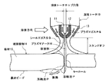
すなわち、前述したようなプラズマアークによるキーホール溶接を行った場合、図2に示すように母材15の裏側であって、キーホール(プラズマアーク)の溶接方向後方には、溶接トーチ10から発生するプラズマアーク16の熱によって溶けた母材15による溶融池Pがその長手方向に沿って形成される。そして、この溶融池Pが、溶接方向前後に揺れることで、安定した一定高さの裏波ビードが形成されることが分かった。このとき溶融池Pの揺れ(挙動)が大きすぎると溶融金属が垂れ落ちてしまうことから溶融池Pの揺れ(挙動)には、安定した一定高さの裏波ビードを形成するための固有の振動数(例えば、30乃至40Hz)が存在することが分かった。また、この固有振動数は、母材15の材質や溶融池Pの大きさ(質量)、粘度などによっても異なる。そして、これらの知見に基づき本発明者らがこの溶融池Pの揺れ(挙動)をさらに詳しく調べたところ、この溶融池Pの揺れ(挙動)は、キーホール溶接時の溶接電流としてパルス電流を使用した場合、そのパルス電流のパルス周波数に大きく影響を受けることが分かった。
That is, when the keyhole welding by the plasma arc as described above is performed, it is generated from the
そこで、前記の目的を達成するために第1の発明は、被溶接物の溶接部にプラズマアークによるキーホールを形成しながら当該溶接部を連続溶接するプラズマアーク溶接方法であって、溶接電流にパルス電流を用いると共に、当該パルス電流のパルス周波数を前記溶接時に母材裏側に形成される溶融池が同期する周波数に制御して溶接することを特徴とするプラズマアーク溶接方法である。 Accordingly, in order to achieve the above object, the first invention is a plasma arc welding method for continuously welding a welded portion of the workpiece to be welded while forming a keyhole by a plasma arc. The plasma arc welding method is characterized in that welding is performed using a pulse current and controlling the pulse frequency of the pulse current to a frequency that synchronizes with the molten pool formed on the back side of the base metal during the welding.
このような溶接方法によれば、キーホール溶接中の溶融池の揺れをパルス電流のパルス周波数と同期するように制御できるため、垂れ落ちや不整がない安定した一定高さの裏波ビードを確実に得ることができる。 According to such a welding method, it is possible to control the fluctuation of the molten pool during keyhole welding so as to synchronize with the pulse frequency of the pulse current, so that a stable and constant back bead without dripping or irregularity can be ensured. Can get to.
第2の発明は、被溶接物の溶接部にプラズマアークによるキーホールを形成しながら当該溶接部を連続溶接するプラズマアーク溶接方法であって、溶接電流としてパルス電流を供給するパルス電流供給ステップと、当該パルス電流のパルス周波数を前記溶融池が同期する周波数に制御するパルス周波数制御ステップとを含むことを特徴とするプラズマアーク溶接方法である。 A second invention is a plasma arc welding method for continuously welding a welded portion of a workpiece to be welded while forming a keyhole by a plasma arc, and a pulse current supply step for supplying a pulsed current as a welding current; And a pulse frequency control step of controlling a pulse frequency of the pulse current to a frequency synchronized with the molten pool.
このような溶接方法によれば、溶接時に母材裏側に形成される溶融池の揺れをパルス電流のパルス周波数に同期するように制御できるため、垂れ落ちや不整がない安定した一定高さの裏波ビードを確実に得ることができる。 According to such a welding method, it is possible to control the fluctuation of the molten pool formed on the back side of the base metal during welding so as to synchronize with the pulse frequency of the pulse current. Wave beads can be obtained reliably.
第3の発明は、第1または第2の発明において、前記パルス電流のパルス周波数を前記溶融池の固有振動数の0.8倍以上3.0倍以下になるように制御することを特徴とするプラズマアーク溶接方法である。このように制御すれば、垂れ落ちや不整がない安定した一定高さの裏波ビードを確実に得ることができる。ここで、前記パルス電流のパルス周波数を前記溶融池の固有振動数の0.8倍以上3.0倍以下としたのは、後述するようにこの範囲を超えると、プラズマアークと溶融池間の干渉が大きくなって、不整ビードや垂れ落ち現象を招く可能性が高くなるからである。 A third invention is characterized in that, in the first or second invention, the pulse frequency of the pulse current is controlled to be not less than 0.8 times and not more than 3.0 times the natural frequency of the weld pool. This is a plasma arc welding method. By controlling in this way, it is possible to reliably obtain a back wave bead having a stable and constant height without sagging or irregularities. Here, the pulse frequency of the pulse current is set to 0.8 times or more and 3.0 times or less of the natural frequency of the molten pool, as will be described later, if this range is exceeded, the interference between the plasma arc and the molten pool This is because there is a high possibility of causing an irregular bead or dripping phenomenon.
第4の発明は、第3の発明において、前記パルス電流のパルス周波数と共に、前記パルス電流のピークまたはベース電流値あるいはパルス幅を制御することを特徴とするプラズマアーク溶接方法である。このような制御方法によれば、前記溶融池の固有振動数の0.8倍以上3.0倍以下の範囲のうちの限界値付近であっても、垂れ落ちや不整がない安定した一定高さの裏波ビードを確実に得ることができる。 A fourth invention is the plasma arc welding method according to the third invention, wherein the peak or base current value or pulse width of the pulse current is controlled together with the pulse frequency of the pulse current. According to such a control method, even in the vicinity of the limit value in the range of 0.8 times or more and 3.0 times or less the natural frequency of the molten pool, a stable constant height without dripping or irregularities. Sasa back bead can be obtained reliably.
第5の発明は、第1または第2の発明において、前記パルス電流のパルス周波数を前記溶融池の固有振動数の1.0倍以上2.0倍以下になるように制御することを特徴とするプラズマアーク溶接方法である。このように制御すれば、垂れ落ちや不整がない安定した一定高さの裏波ビードをより確実に得ることができる。 A fifth invention is characterized in that, in the first or second invention, the pulse frequency of the pulse current is controlled to be not less than 1.0 times and not more than 2.0 times the natural frequency of the weld pool. This is a plasma arc welding method. By controlling in this way, it is possible to more reliably obtain a back wave bead having a stable and constant height without sagging or irregularities.
第6の発明は、第5の発明において、前記パルス電流のパルス周波数と共に、前記パルス電流のピークまたはベース電流値あるいはパルス幅を制御することを特徴とするプラズマアーク溶接方法である。このような制御方法によれば、前記溶融池の固有振動数の1.0倍以上2.0倍以下の範囲のうちの限界値付近であっても、垂れ落ちや不整がない安定した一定高さの裏波ビードを確実に得ることができる。 A sixth invention is the plasma arc welding method according to the fifth invention, wherein the peak or base current value or pulse width of the pulse current is controlled together with the pulse frequency of the pulse current. According to such a control method, even in the vicinity of a limit value in the range of 1.0 to 2.0 times the natural frequency of the molten pool, a stable constant height without dripping or irregularity is obtained. Sasa back bead can be obtained reliably.
第7の発明は、プラズマアークを発生する溶接トーチを用いて被溶接物の溶接部にキーホールを形成しながら当該溶接部を連続溶接するプラズマアーク溶接装置であって、溶接電流としてパルス電流を供給するパルス電流供給手段と、当該パルス電流のパルス周波数を前記溶融池が同期する周波数に制御するパルス周波数制御手段とを備えたことを特徴とするプラズマアーク溶接装置である。 A seventh invention is a plasma arc welding apparatus for continuously welding a welded portion while forming a keyhole in a welded portion of an object to be welded using a welding torch that generates a plasma arc, wherein a pulse current is used as a welding current. A plasma arc welding apparatus comprising: a supplied pulse current supply means; and a pulse frequency control means for controlling a pulse frequency of the pulse current to a frequency synchronized with the molten pool.
このような構成によれば、第2の発明と同様に、溶接時に母材裏側に形成される溶融池の揺れをパルス電流のパルス周波数と同期するように制御できるため、垂れ落ちや不整がない安定した一定高さの裏波ビードを確実に得ることができる。 According to such a configuration, similarly to the second invention, since the fluctuation of the molten pool formed on the back side of the base metal during welding can be controlled to be synchronized with the pulse frequency of the pulse current, there is no dripping or irregularity. A stable and constant back bead can be reliably obtained.
本発明によれば、溶接電流にパルス電流を用いると共に、このパルス電流のパルス周波数を溶接時に母材裏側に形成される溶融池が同期する周波数に制御して溶接する。これによって、キーホール溶接に際して垂れ落ちや不整がない安定した一定高さの裏波ビードを確実に得ることができる。 According to the present invention, a pulse current is used as a welding current, and the pulse frequency of this pulse current is controlled to a frequency that synchronizes with the molten pool formed on the back side of the base material during welding. As a result, it is possible to reliably obtain a back wave bead having a stable and constant height without sagging or irregularities during keyhole welding.
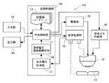
次に、本発明に係るプラズマアーク溶接方法および溶接装置の実施の一形態を添付図面を参照しながら説明する。図1は、本発明に係るプラズマアーク溶接装置100の構成を示したブロック図である。図示するようにこのプラズマアーク溶接装置100は、溶接トーチ10と、この溶接トーチ10を駆動する駆動部20と、溶接電源を供給する電源部30と、溶接トーチ10に溶接ガスを供給するガス供給部40と、これら各部10乃至40を制御する溶接制御部50とから主に構成されている。
Next, an embodiment of a plasma arc welding method and a welding apparatus according to the present invention will be described with reference to the accompanying drawings. FIG. 1 is a block diagram showing a configuration of a plasma
溶接トーチ10は、図2に示すように、タングステン電極11を溶接トーチチップ12で覆うと共にその溶接トーチチップ12をシールドキャップ13で覆った構造をしている。そして、図示しない高周波発生器を使ってこのタングステン電極11と溶接トーチチップ12との間にパイロットアークを発生させると共に、その溶接トーチチップ12内にアルゴン(Ar)などの動作ガス(プラズマガスPG)を流すと、このプラズマガスPGがアーク熱によってイオン化してアーク電流の良導体となってタングステン電極11と母材15間で超高温(10000〜20000℃)のプラズマアーク16が発生するようになっている。そして、このプラズマアーク16を母材15の表側から裏面側に貫通させることでキーホール溶接が可能となっている。また、この溶接トーチチップ12とシールドキャップ13間にはアルゴン(Ar)と水素(H2)、アルゴン(Ar)と酸素(O2)、アルゴン(Ar)と炭酸ガス(CO2)などからなるシールドガスSGが供給されており、このシールドガスSGによって溶接部を大気から保護して溶接品質を維持するようになっている。
As shown in FIG. 2, the
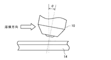
駆動部20は、この溶接トーチ10を被溶接物14に対して例えば図3に示すように所定の間隔および角度θとなるように維持・固定すると共に、溶接制御部50からの制御信号によってその溶接トーチ10を被溶接物14の溶接線に沿って所定の速度で移動(走行)させるようになっている。なお、この駆動部20は、被溶接物14側を固定し、この被溶接物14に対して溶接トーチ10側を移動させる他、溶接トーチ10側を固定し、被溶接物14側を移動させたり、両方をそれぞれ同時に移動(走行)させることも可能となっている。
The
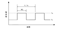
溶接電源部30は、溶接トーチ10と母材15との間にプラズマアーク16を発生させるために必要な電流を所定の電圧で供給するものであり、その電流値および電圧値は溶接制御部50によって細かく制御されるようになっている。そして、この溶接電源部30は、供給する電流として例えば図4に示すような矩形波のパルス電流を供給するようになっている。図4はこの溶接電源部30から供給されるパルス電流の波形の一例を示したものであり、Ipはピーク電流、Ibはベース電流、wpはパルス幅、f1はパルス周波数である。ガス供給部40は、溶接トーチ10に対して前述したプラズマガスやシールドガスなどの溶接ガスを供給するものであり、同じく溶接制御部50によってそのガス流量やタイミングなどが適宜制御されるようになっている。
The welding
溶接制御部50は、中央制御部51と、記憶部(データベース)52と、出力電圧計測部53と、溶接電圧周波数解析部56と、入力部54と、出力部55とから構成されている。そして先ず中央制御部51は、コンピュータシステムなどの情報処理装置(CPU、ROM、RAM、入出力インタフェースなど)から構成されており、入力部54から入力される操作指令や所定の制御用プログラムに基づいて前記各部10乃至40などを制御するようになっている。
The
記憶部(データベース)52は、HDDや半導体メモリなどのデータの書き込み・読み出し自在の記憶装置などから構成されており、各種制御用プログラムなどの他に、少なくとも各種溶接条件とその溶接条件毎に異なる、溶接時に母材15の裏側に形成される溶融池の固有振動数に関するデータが書き込み・読み出し自在に記録されている。 The storage unit (database) 52 includes a storage device that can freely write and read data, such as an HDD and a semiconductor memory. In addition to various control programs, the storage unit (database) 52 differs at least for each welding condition and each welding condition. Data relating to the natural frequency of the molten pool formed on the back side of the base material 15 during welding is recorded so as to be freely written and read.
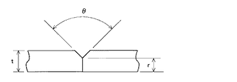
すなわち、この記憶部(データベース)52には、少なくとも様々な溶接条件とその条件下で一意に決まる溶融池Pの固有振動数に関する情報がデータベースとして記録されている。ここで、様々な溶接条件としては、例えば被溶接物14に関する条件と溶接施工条件とが挙げられる。そして、被溶接物14に関する条件としては、材料(母材の種類)の他に、例えば図5に示すように板厚t、開先角度θ、ルート長さrなどがある。一方、溶接施工条件としては、溶接電流、溶接速度、パイロットガス流量、パイロットガス組成、シールドガス組成、溶接トーチチップ穴径、スタンドオフ(母材−溶接トーチチップ間隔)、図3に示すように被溶接物14に対する溶接トーチ10の角度θなどがある。
That is, in the storage unit (database) 52, information on at least various welding conditions and the natural frequency of the weld pool P uniquely determined under the conditions is recorded as a database. Here, as various welding conditions, the conditions regarding the to-
出力電圧計測部53は、溶接電源部30からの出力電圧を常時あるいは任意の時間計測して溶接電圧周波数解析部56と中央制御部51に入力するようになっている。入力部54は、例えばキーボードやマウスなどの各種入力装置から構成されており、各種の溶接条件や操作指令などを入力するようになっている。出力部はCRTやLCDなどのモニターやスピーカーなどの各種出力装置から構成されており、入力部54からの溶接条件の入力操作の確認のための表示や各種の溶接状況などの情報を表示するようになっている。なお、この出力部55はモニターの表面にタッチパネルなどの入力機能を付加することで入力部54と兼用しても良い。
The output
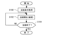
このような構成をした本発明に係るプラズマアーク溶接装置100によるプラズマ溶接方法としては、例えば図6に示すような流れとなる。すなわち、本発明装置100の溶接制御部50(中央制御部51)は、入力部54から被溶接物14に関する条件と溶接開始指令が入力されたならば、最初のステップS100に移行してその被溶接物14に関する条件に最適な溶接施工条件を記憶部(データベース)52から選択してきてその溶接施工条件を取得して次のステップS102に移行する。
As a plasma welding method by the plasma
ステップS102では、溶接電源30により、パルス電流のパルス周波数を溶融池Pが同期する周波数に設定し、溶接を開始する。そして、この溶接制御部50(中央制御部51)は、最後のステップS104に移行してその溶接が終了したか否かを判断し、溶接が終了したと判断したとき(YES)は、その処理を終了するが、終了していないと判断したとき(YES)は、ステップS102に戻って溶接作業を継続する。
In step S102, the
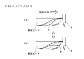
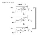
図7乃至図9は、溶融池Pの挙動に対するパルス電流のパルス周波数(f1)の影響を示したものである。先ず、図7はパルス電流のパルス周波数(f1)が、溶融池Pの固有振動数(fp)の0.8倍以上1.0倍以下(0.8≦f1/fp≦1.0)の場合の溶融池Pの挙動(振動)を示した模式図である。 7 to 9 show the influence of the pulse frequency (f 1 ) of the pulse current on the behavior of the molten pool P. FIG. First, in FIG. 7, the pulse frequency (f 1 ) of the pulse current is 0.8 times or more and 1.0 times or less (0.8 ≦ f 1 / f p ≦ 1) of the natural frequency (f p ) of the weld pool P. .0) is a schematic diagram showing the behavior (vibration) of the weld pool P.
同図(A)に示すように、この溶融池Pは、ピーク電流Ipが流れたときにその駆動力によって溶接方向逆向きの波(揺れ)が形成される。この波は、溶融池P後端に達したときにその一部が固まって裏波ビードを形成し、残りはベース電流Ib下で同図(B)に示すように、その溶融池P後端で反射して溶接方向の波となる。この波は、キーホールを突き抜けたプラズマアーク16と干渉することによって減衰される。このような揺れ(振動)を繰り返すことで、垂れ落ちや不整がない安定した一定高さの裏波ビードが形成される。
As shown in FIG. 5A, in the molten pool P, when the peak current Ip flows, a wave (swaying) in the direction opposite to the welding direction is formed by the driving force. This wave, and form a part of the solidified penetration bead upon reaching the molten pool P rear, rest as shown in (B) under the base current I b, after the molten pool P It is reflected at the edge and becomes a wave in the welding direction. This wave is attenuated by interfering with the
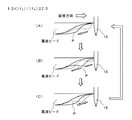
次に、図8はパルス電流のパルス周波数(f1)が、溶融池Pの固有振動数(fp)の1.0倍を越え2.0倍以下(1.0<f1/fp≦2.0)の場合の溶融池Pの挙動(振動)を示した模式図である。この場合も同様に先ず、同図(A)に示すように、溶融池Pは、ピーク電流Ipが流れたときに、その駆動力によって溶接方向逆向きの波(揺れ)が形成される。この波は、溶融池P後端に達したときにその一部が固まって裏波ビードを形成し、残りはベース電流Ib下でその溶融池P後端で反射して溶接方向の波となる。この波は、同図(B)に示すように、溶融池Pの先端側に達する前に、溶融池Pのほぼ中央部において、次のピーク電流Ipによってキーホール側で発生した溶接方向逆向きの新たな溶融金属の波と交差する。それぞれの波は交差することで同図(C)に示すように減衰して、溶融池P全体の振動が抑えられる。このため、溶融金属量が多い場合でも溶け落ちやプラズマアーク16への干渉を抑えることができる。これによって、垂れ落ちや不整がない安定した一定高さの裏波ビードが形成される。
Next, FIG. 8 shows that the pulse frequency (f 1 ) of the pulse current exceeds 1.0 times the natural frequency (f p ) of the weld pool P and is 2.0 times or less (1.0 <f 1 / f p It is the schematic diagram which showed the behavior (vibration) of the molten pool P in the case of <= 2.0). In this case as well, first, as shown in FIG. 5A, when the peak current Ip flows, the weld pool P generates waves (swings) in the direction opposite to the welding direction. This wave, molten pool portion thereof when it reaches the P rear end hardens to form a penetration bead, rest and wave welding direction is reflected at the molten pool P rear under the base current I b Become. As shown in FIG. 2B, this wave is reverse in the welding direction generated on the keyhole side by the next peak current Ip in the substantially central portion of the molten pool P before reaching the tip side of the molten pool P. Cross with new molten metal waves. By crossing each wave, it attenuates as shown in FIG. 3C, and vibration of the entire weld pool P is suppressed. For this reason, even when the amount of molten metal is large, it is possible to suppress melt-off and interference with the
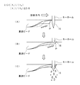
次に、図9はパルス電流のパルス周波数(f1)が、溶融池Pの固有振動数(fp)の2.0倍を越え3.0倍以下(2.0<f1/fp≦3.0)の場合の溶融池Pの挙動(振動)を示した模式図である。この場合も同様に先ず、同図(A)に示すように、溶融池Pは、ピーク電流Ipが流れたときに、その駆動力によって溶接方向逆向きの波(揺れ)が形成される。しかし、この場合は、ピーク時間(パルス幅wp/パルス周波数f1)が短いため、ピーク電流時に溶融される金属量も少なく、同図(B)に示すように、溶融池Pの揺れも上記の場合よりも小さい。このため、反射波も次のピーク電流Ip以降に溶融される溶融金属の波により打ち消され、溶融池Pには、同図(C)に示すように、パルス周波数に同期した後端方向への振動した流れが発生する。これによって、垂れ落ちや不整がない安定した一定高さの裏波ビードが形成される。 Next, FIG. 9 shows that the pulse frequency (f 1 ) of the pulse current exceeds 2.0 times the natural frequency (f p ) of the weld pool P and is 3.0 times or less (2.0 <f 1 / f p It is the schematic diagram which showed the behavior (vibration) of the molten pool P in the case of <= 3.0). In this case as well, first, as shown in FIG. 5A, when the peak current Ip flows, the weld pool P generates waves (swings) in the direction opposite to the welding direction. However, in this case, since the peak time (pulse width w p / pulse frequency f 1 ) is short, the amount of metal melted at the peak current is small, and as shown in FIG. It is smaller than the above case. For this reason, the reflected wave is also canceled by the molten metal wave melted after the next peak current Ip , and the molten pool P is moved toward the rear end in synchronization with the pulse frequency as shown in FIG. The oscillating flow of is generated. As a result, a stable and constant back bead without sagging or irregularity is formed.
一方、図10はパルス電流のパルス周波数(f1)が溶融池Pの固有振動数(fp)の0.8倍未満の場合、およびパルス電流のパルス周波数(f1)が溶融池Pの固有振動数(fp)の0.8倍未満および3.0倍を超える場合の下部溶融池Pの挙動(振動)を示した模式図である。これらの場合、溶融池Pは、パルス周波数(f1)と同期せずに固有振動数(fp)で振動しようとするため、同図(A)および(B)に示すようにこの溶融池Pの溶融金属がプラズマアーク16に干渉してキーホールを一時的に閉じてしまうことがある。その結果、同図(C)に示すようにプラズマアーク16が再びキーホールを形成する際にこの溶融金属を一気に押し退けるように作用してスパッタの発生や垂れ落ちなどの溶接不良を招く可能性があるため、安定した一定高さの裏波ビードを得ることが難しい。
On the other hand, FIG. 10 when the pulse current of the pulse frequency (f 1) is less than 0.8 times the natural frequency (f p) of the molten pool P, and the pulse current of the pulse frequency (f 1) of the molten pool P it is a schematic view showing the behavior of the lower molten pool P (vibration) in the case of more than and 3.0 times less than 0.8 times the natural frequency (f p). In these cases, since the molten pool P tries to vibrate at the natural frequency (f p ) without being synchronized with the pulse frequency (f 1 ), as shown in FIGS. The P molten metal may interfere with the
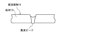
このように本発明は、溶接電流にパルス電流を用いると共に、このパルス電流のパルス周波数を溶融池Pが同期する周波数に制御して溶接するため、図11に示すようにキーホール溶接に際して垂れ落ちや不整がない安定した一定高さの裏波ビードを確実に得ることができる。 As described above, the present invention uses a pulse current as a welding current and controls the pulse frequency of the pulse current to a frequency synchronized with the weld pool P so that welding is performed. It is possible to reliably obtain a stable and constant back bead without any irregularities.
また、このようにパルス電流のパルス周波数を所定の範囲内に収まるように制御すると共に、図4に示すようにパルス電流のピーク電流値(Ip)またはベース電流値(Ib)あるいはパルス幅を制御しても良い。このようにすれば、パルス電流のパルス周波数が溶融池Pの固有振動数の0.8倍以上3.0倍以下の範囲のうちの限界値付近、すなわち0.8倍付近または3.0倍付近であっても、ピーク電流値(Ip)またはベース電流値(Ib)あるいはパルス幅のいずれかあるいは複合して制御すれば、垂れ落ちや不整がない安定した一定高さの裏波ビードを確実に得ることができる。 In addition, the pulse frequency of the pulse current is controlled so as to be within a predetermined range as described above, and the peak current value (I p ) or base current value (I b ) or pulse width of the pulse current as shown in FIG. May be controlled. In this case, the pulse frequency of the pulse current is in the vicinity of the limit value in the range of 0.8 to 3.0 times the natural frequency of the weld pool P, that is, near 0.8 times or 3.0 times. Even if it is near, if the peak current value (I p ), base current value (I b ) or pulse width is controlled or combined, it will be stable and constant back bead without dripping or irregularity Can be definitely obtained.
なお、前記課題を解決するための手段の欄に記載した本発明を構成する各手段(ステップ)のうち、溶接電流としてパルス電流を供給するパルス電流供給手段(ステップ)は、図1の溶接電源部30に対応する。
Of the means (steps) constituting the present invention described in the section for solving the problems, the pulse current supply means (step) for supplying a pulse current as a welding current is the welding power source shown in FIG. This corresponds to
100…プラズマアーク溶接装置
11…タングステン電極
12…溶接トーチチップ
10…溶接トーチ
13…シールドキャップ
14…被溶接物
15…母材
16…プラズマアーク
20…駆動部
30…溶接電源部
40…溶接ガス供給部
50…溶接制御部
51…中央制御部
52…記憶部(データベース)
53…出力電圧計測部
54…入力部
55…出力部
56…溶接電圧周波数解析部
P…溶融池
PG…プラズマガス
SG…シールドガス
DESCRIPTION OF
53 ... Output
Claims (5)
溶接電流にパルス電流を用いると共に、当該パルス電流のパルス周波数を前記溶接時に母材裏側に形成される溶融池が同期する周波数に制御して溶接するに際し、
前記パルス電流のパルス周波数を前記溶融池の固有振動数の0.8倍以上3.0倍以下になるように制御することを特徴とするプラズマアーク溶接方法。 A plasma arc welding method for continuously welding the welded part while forming a keyhole by a plasma arc in the welded part of the workpiece,
When using a pulse current for the welding current and controlling the pulse frequency of the pulse current to a frequency synchronized with the weld pool formed on the back side of the base metal during the welding,
A plasma arc welding method, wherein a pulse frequency of the pulse current is controlled to be 0.8 times or more and 3.0 times or less of a natural frequency of the molten pool.
前記パルス電流のパルス周波数と共に、前記パルス電流のピークまたはベース電流値あるいはパルス幅を制御することを特徴とするプラズマアーク溶接方法。 In the plasma arc welding method according to claim 1 ,
The plasma arc welding method characterized by controlling the peak or base current value or pulse width of the pulse current together with the pulse frequency of the pulse current.
溶接電流にパルス電流を用いると共に、当該パルス電流のパルス周波数を前記溶接時に母材裏側に形成される溶融池が同期する周波数に制御して溶接するに際し、
前記パルス電流のパルス周波数を前記溶融池の固有振動数の1.0倍以上2.0倍以下になるように制御することを特徴とするプラズマアーク溶接方法。 A plasma arc welding method for continuously welding the welded part while forming a keyhole by a plasma arc in the welded part of the workpiece,
When using a pulse current for the welding current and controlling the pulse frequency of the pulse current to a frequency synchronized with the weld pool formed on the back side of the base metal during the welding,
A plasma arc welding method, wherein a pulse frequency of the pulse current is controlled to be 1.0 to 2.0 times a natural frequency of the molten pool.
前記パルス電流のパルス周波数と共に、前記パルス電流のピークまたはベース電流値あるいはパルス幅を制御することを特徴とするプラズマアーク溶接方法。 In the plasma arc welding method according to claim 3 ,
The plasma arc welding method characterized by controlling the peak or base current value or pulse width of the pulse current together with the pulse frequency of the pulse current.
前記溶接電流としてパルス電流を供給するパルス電流供給手段と、当該パルス電流のパルス周波数を前記溶融池の固有振動数の0.8倍以上3.0倍以下になるように制御するパルス周波数制御手段とを備えたことを特徴とするプラズマアーク溶接装置。 A plasma arc welding apparatus that continuously welds a welded portion while forming a keyhole in a welded portion of an object to be welded using a welding torch that generates a plasma arc,
Pulse current supply means for supplying a pulse current as the welding current, and pulse frequency control means for controlling the pulse frequency of the pulse current to be 0.8 times or more and 3.0 times or less the natural frequency of the weld pool A plasma arc welding apparatus comprising:
Priority Applications (6)
| Application Number | Priority Date | Filing Date | Title |
|---|---|---|---|
| JP2011251738A JP5820249B2 (en) | 2011-11-17 | 2011-11-17 | Plasma arc welding method and plasma arc welding apparatus |
| RU2014123729/02A RU2579851C2 (en) | 2011-11-17 | 2012-11-16 | Method for plasma arc welding and device for plasma arc welding |
| US14/358,655 US9375802B2 (en) | 2011-11-17 | 2012-11-16 | Plasma arc welding method and plasma arc welding device |
| PCT/JP2012/079746 WO2013073655A1 (en) | 2011-11-17 | 2012-11-16 | Plasma arc welding method and plasma arc welding device |
| CN201280056461.XA CN103945974B (en) | 2011-11-17 | 2012-11-16 | Plasma arc welding method and plasma arc welding device |
| EP12849073.7A EP2781293B1 (en) | 2011-11-17 | 2012-11-16 | Plasma arc welding method and plasma arc welding device |
Applications Claiming Priority (1)
| Application Number | Priority Date | Filing Date | Title |
|---|---|---|---|
| JP2011251738A JP5820249B2 (en) | 2011-11-17 | 2011-11-17 | Plasma arc welding method and plasma arc welding apparatus |
Publications (2)
| Publication Number | Publication Date |
|---|---|
| JP2013107086A JP2013107086A (en) | 2013-06-06 |
| JP5820249B2 true JP5820249B2 (en) | 2015-11-24 |
Family
ID=48429708
Family Applications (1)
| Application Number | Title | Priority Date | Filing Date |
|---|---|---|---|
| JP2011251738A Active JP5820249B2 (en) | 2011-11-17 | 2011-11-17 | Plasma arc welding method and plasma arc welding apparatus |
Country Status (6)
| Country | Link |
|---|---|
| US (1) | US9375802B2 (en) |
| EP (1) | EP2781293B1 (en) |
| JP (1) | JP5820249B2 (en) |
| CN (1) | CN103945974B (en) |
| RU (1) | RU2579851C2 (en) |
| WO (1) | WO2013073655A1 (en) |
Families Citing this family (5)
| Publication number | Priority date | Publication date | Assignee | Title |
|---|---|---|---|---|
| US20170120365A1 (en) * | 2015-10-29 | 2017-05-04 | Lincoln Global, Inc. | System and method of communicating in a welding system over welding power cables |
| CN111602471A (en) * | 2018-01-23 | 2020-08-28 | 株式会社富士 | Plasma generator and information processing method |
| CN112091429A (en) * | 2020-08-21 | 2020-12-18 | 广东省科学院中乌焊接研究所 | Aluminum alloy welding method |
| US12447641B2 (en) * | 2021-05-03 | 2025-10-21 | The Gillette Company Llc | Welded razor blade assemblies |
| CN117206638B (en) * | 2023-09-19 | 2025-04-01 | 中国核工业第五建设有限公司 | A composite TIG welding method |
Family Cites Families (21)
| Publication number | Priority date | Publication date | Assignee | Title |
|---|---|---|---|---|
| US4595820A (en) * | 1982-10-22 | 1986-06-17 | The Ohio State University | Apparatus and methods for controlling a welding process |
| JPS6027473A (en) | 1983-07-26 | 1985-02-12 | Mitsubishi Heavy Ind Ltd | Plasma welding method |
| US4711986A (en) * | 1986-11-24 | 1987-12-08 | General Electric Company | Method and apparatus for measuring weld penetration in an arc welding process |
| SU1558603A1 (en) * | 1987-04-15 | 1990-04-23 | Сибирский автомобильно-дорожный институт им.В.В.Куйбышева | Method of gas-shielded consumable-electrode welding |
| US5225654A (en) * | 1992-07-15 | 1993-07-06 | The Babcock & Wilcox Company | Method for defect free keyhole plasma arc welding |
| JP3018807B2 (en) * | 1993-01-20 | 2000-03-13 | トヨタ自動車株式会社 | Consumable electrode type pulse arc welding equipment |
| JPH07214330A (en) | 1994-02-07 | 1995-08-15 | Kobe Steel Ltd | Three o'clock plasma arc welding |
| US5506384A (en) * | 1994-04-21 | 1996-04-09 | Kabushiki Kaisha Komatsu Seisakusho | Plasma arc cutting machine with variable constant current source and variable resistor |
| JPH0839259A (en) | 1994-07-29 | 1996-02-13 | Kobe Steel Ltd | Gas pulse plasma welding method |
| JP3327457B2 (en) * | 1997-09-26 | 2002-09-24 | トヨタ自動車株式会社 | Pulse arc welding method |
| UA43424C2 (en) * | 1998-02-26 | 2001-12-17 | Інститут Електрозварювання Ім. Є.О. Патона Нан України | Method of arc welding by consumable electrode under shielding gases |
| JP3681964B2 (en) * | 2000-08-02 | 2005-08-10 | ダイハツ工業株式会社 | Arc welding method and arc welding equipment |
| JP2002178177A (en) | 2000-12-07 | 2002-06-25 | Babcock Hitachi Kk | Laser beam welding machine |
| US6977357B2 (en) * | 2003-07-09 | 2005-12-20 | Lincoln Global, Inc. | Welding wire positioning system |
| JP2007152399A (en) * | 2005-12-06 | 2007-06-21 | Mitsubishi Heavy Ind Ltd | Welding method |
| JP5124765B2 (en) * | 2006-08-30 | 2013-01-23 | 独立行政法人国立高等専門学校機構 | Welding method and welding apparatus using electromagnetic force |
| RU2343651C1 (en) * | 2007-06-13 | 2009-01-10 | Государственное Научное Учреждение "Институт Физики Имени Б.И. Степанова Национальной Академии Наук Беларуси" | Pulse-periodic plasmatron |
| US8324524B2 (en) * | 2008-03-26 | 2012-12-04 | Taiyo Nippon Sanso Corporation | Plasma welding process and outer gas for use in the plasma welding process |
| JP2010172958A (en) * | 2009-02-02 | 2010-08-12 | Daihen Corp | Plasma gma welding method |
| JP2010207875A (en) * | 2009-03-11 | 2010-09-24 | Panasonic Corp | Composite welding equipment |
| JP5558881B2 (en) * | 2010-03-29 | 2014-07-23 | 株式会社ダイヘン | Plasma MIG welding method |
-
2011
- 2011-11-17 JP JP2011251738A patent/JP5820249B2/en active Active
-
2012
- 2012-11-16 EP EP12849073.7A patent/EP2781293B1/en not_active Not-in-force
- 2012-11-16 CN CN201280056461.XA patent/CN103945974B/en not_active Expired - Fee Related
- 2012-11-16 WO PCT/JP2012/079746 patent/WO2013073655A1/en not_active Ceased
- 2012-11-16 RU RU2014123729/02A patent/RU2579851C2/en not_active IP Right Cessation
- 2012-11-16 US US14/358,655 patent/US9375802B2/en not_active Expired - Fee Related
Also Published As
| Publication number | Publication date |
|---|---|
| RU2579851C2 (en) | 2016-04-10 |
| US9375802B2 (en) | 2016-06-28 |
| RU2014123729A (en) | 2015-12-27 |
| JP2013107086A (en) | 2013-06-06 |
| EP2781293A1 (en) | 2014-09-24 |
| WO2013073655A1 (en) | 2013-05-23 |
| US20140312012A1 (en) | 2014-10-23 |
| EP2781293B1 (en) | 2018-04-11 |
| EP2781293A4 (en) | 2015-09-02 |
| CN103945974B (en) | 2017-02-22 |
| CN103945974A (en) | 2014-07-23 |
Similar Documents
| Publication | Publication Date | Title |
|---|---|---|
| JP5820249B2 (en) | Plasma arc welding method and plasma arc welding apparatus | |
| Zhang et al. | Arc characteristics and metal transfer behavior in narrow gap gas metal arc welding process | |
| JP2005118872A (en) | Pulse arc welding output control method and arc length variation pulse arc welding output control method | |
| KR101991608B1 (en) | Horizontal fillet welding method, horizontal fillet welding system and program | |
| JP2013107087A (en) | Monitoring method of plasma arc welding and plasma arc welding device | |
| JP2015501727A (en) | DC electrode minus rotary arc welding method and system | |
| e Silva et al. | Effect of dynamic wire in the GTAW process | |
| CN101269433B (en) | Arc starting method for double-electrode arc welding | |
| CN105722629A (en) | System and method for automatic height adjustment of a torch | |
| KR101991607B1 (en) | Horizontal Fillet Welding Method, Horizontal Fillet Welding System and Program | |
| JP3089060B2 (en) | Automatic welding equipment | |
| JP2019150857A (en) | Adjustment method for workpiece posture, and method of and device for producing molded material | |
| JP5820248B2 (en) | Plasma arc welding method and plasma arc welding apparatus | |
| CN103687688B (en) | A kind of method and source of welding current operating the source of welding current | |
| CN201950346U (en) | Narrow gap double wire MIG/MAG welding apparatus | |
| JP2011110604A (en) | Pulse arc welding method and welding apparatus | |
| JP2010214462A (en) | Arc welding equipment | |
| Karimi et al. | Processing characteristics of Ni-WC MMC weld cladding by various types of GMAW | |
| JP2008105095A (en) | Output control method for pulsed arc welding | |
| Zheng et al. | A novel control approach for the droplet detachment in rapid prototyping by 3D welding | |
| Saraev et al. | The development and practical application of adaptive pulse-arc welding in the manufacturing and repair of metal structures responsible function | |
| JP2009233739A (en) | Welding method and apparatus | |
| JP2010179353A (en) | Gas-shield arc welding method | |
| JP2007210019A (en) | Welding device and welding method | |
| JP4638246B2 (en) | Straightening device |
Legal Events
| Date | Code | Title | Description |
|---|---|---|---|
| A621 | Written request for application examination |
Free format text: JAPANESE INTERMEDIATE CODE: A621 Effective date: 20140224 |
|
| A131 | Notification of reasons for refusal |
Free format text: JAPANESE INTERMEDIATE CODE: A131 Effective date: 20150519 |
|
| A521 | Written amendment |
Free format text: JAPANESE INTERMEDIATE CODE: A523 Effective date: 20150721 |
|
| TRDD | Decision of grant or rejection written | ||
| A01 | Written decision to grant a patent or to grant a registration (utility model) |
Free format text: JAPANESE INTERMEDIATE CODE: A01 Effective date: 20150915 |
|
| A61 | First payment of annual fees (during grant procedure) |
Free format text: JAPANESE INTERMEDIATE CODE: A61 Effective date: 20151002 |
|
| R150 | Certificate of patent or registration of utility model |
Ref document number: 5820249 Country of ref document: JP Free format text: JAPANESE INTERMEDIATE CODE: R150 |
|
| S111 | Request for change of ownership or part of ownership |
Free format text: JAPANESE INTERMEDIATE CODE: R313115 |
|
| R350 | Written notification of registration of transfer |
Free format text: JAPANESE INTERMEDIATE CODE: R350 |