JP5809635B2 - Pedicle locking device and system for locking a pedicle locking device - Google Patents
Pedicle locking device and system for locking a pedicle locking device Download PDFInfo
- Publication number
- JP5809635B2 JP5809635B2 JP2012537278A JP2012537278A JP5809635B2 JP 5809635 B2 JP5809635 B2 JP 5809635B2 JP 2012537278 A JP2012537278 A JP 2012537278A JP 2012537278 A JP2012537278 A JP 2012537278A JP 5809635 B2 JP5809635 B2 JP 5809635B2
- Authority
- JP
- Japan
- Prior art keywords
- pedicle
- locking device
- liquefiable
- longitudinal bore
- locking
- Prior art date
- Legal status (The legal status is an assumption and is not a legal conclusion. Google has not performed a legal analysis and makes no representation as to the accuracy of the status listed.)
- Expired - Fee Related
Links
- 239000000463 material Substances 0.000 claims description 138
- 210000001519 tissue Anatomy 0.000 claims description 63
- 210000000988 bone and bone Anatomy 0.000 claims description 50
- 241001465754 Metazoa Species 0.000 claims description 4
- 230000000399 orthopedic effect Effects 0.000 claims description 2
- 230000000087 stabilizing effect Effects 0.000 claims description 2
- 239000007943 implant Substances 0.000 description 54
- 238000000034 method Methods 0.000 description 48
- 238000003780 insertion Methods 0.000 description 33
- 230000037431 insertion Effects 0.000 description 33
- 230000002787 reinforcement Effects 0.000 description 22
- 229920000642 polymer Polymers 0.000 description 21
- 239000004568 cement Substances 0.000 description 16
- 230000008569 process Effects 0.000 description 15
- 229920001169 thermoplastic Polymers 0.000 description 15
- 239000012815 thermoplastic material Substances 0.000 description 15
- 230000003014 reinforcing effect Effects 0.000 description 14
- 239000003814 drug Substances 0.000 description 12
- 229940079593 drug Drugs 0.000 description 12
- 230000000694 effects Effects 0.000 description 12
- 239000000126 substance Substances 0.000 description 11
- 239000004416 thermosoftening plastic Substances 0.000 description 11
- 239000011396 hydraulic cement Substances 0.000 description 10
- 238000002513 implantation Methods 0.000 description 9
- 239000000945 filler Substances 0.000 description 8
- 239000003102 growth factor Substances 0.000 description 8
- 230000035876 healing Effects 0.000 description 8
- QORWJWZARLRLPR-UHFFFAOYSA-H tricalcium bis(phosphate) Chemical compound [Ca+2].[Ca+2].[Ca+2].[O-]P([O-])([O-])=O.[O-]P([O-])([O-])=O QORWJWZARLRLPR-UHFFFAOYSA-H 0.000 description 8
- 239000003795 chemical substances by application Substances 0.000 description 7
- 230000009969 flowable effect Effects 0.000 description 7
- 230000004069 differentiation Effects 0.000 description 6
- 230000012010 growth Effects 0.000 description 6
- 102000004169 proteins and genes Human genes 0.000 description 6
- 108090000623 proteins and genes Proteins 0.000 description 6
- 239000012779 reinforcing material Substances 0.000 description 6
- 230000006641 stabilisation Effects 0.000 description 6
- 238000011105 stabilization Methods 0.000 description 6
- 239000010936 titanium Substances 0.000 description 6
- 206010017076 Fracture Diseases 0.000 description 5
- 239000001506 calcium phosphate Substances 0.000 description 5
- 229910000389 calcium phosphate Inorganic materials 0.000 description 5
- 235000011010 calcium phosphates Nutrition 0.000 description 5
- 230000033001 locomotion Effects 0.000 description 5
- 239000000203 mixture Substances 0.000 description 5
- 229920000747 poly(lactic acid) Polymers 0.000 description 5
- 239000003381 stabilizer Substances 0.000 description 5
- 238000001356 surgical procedure Methods 0.000 description 5
- VTYYLEPIZMXCLO-UHFFFAOYSA-L Calcium carbonate Chemical compound [Ca+2].[O-]C([O-])=O VTYYLEPIZMXCLO-UHFFFAOYSA-L 0.000 description 4
- 102000010780 Platelet-Derived Growth Factor Human genes 0.000 description 4
- 108010038512 Platelet-Derived Growth Factor Proteins 0.000 description 4
- 230000009471 action Effects 0.000 description 4
- 150000001875 compounds Chemical class 0.000 description 4
- 230000001054 cortical effect Effects 0.000 description 4
- 238000011065 in-situ storage Methods 0.000 description 4
- NOESYZHRGYRDHS-UHFFFAOYSA-N insulin Chemical compound N1C(=O)C(NC(=O)C(CCC(N)=O)NC(=O)C(CCC(O)=O)NC(=O)C(C(C)C)NC(=O)C(NC(=O)CN)C(C)CC)CSSCC(C(NC(CO)C(=O)NC(CC(C)C)C(=O)NC(CC=2C=CC(O)=CC=2)C(=O)NC(CCC(N)=O)C(=O)NC(CC(C)C)C(=O)NC(CCC(O)=O)C(=O)NC(CC(N)=O)C(=O)NC(CC=2C=CC(O)=CC=2)C(=O)NC(CSSCC(NC(=O)C(C(C)C)NC(=O)C(CC(C)C)NC(=O)C(CC=2C=CC(O)=CC=2)NC(=O)C(CC(C)C)NC(=O)C(C)NC(=O)C(CCC(O)=O)NC(=O)C(C(C)C)NC(=O)C(CC(C)C)NC(=O)C(CC=2NC=NC=2)NC(=O)C(CO)NC(=O)CNC2=O)C(=O)NCC(=O)NC(CCC(O)=O)C(=O)NC(CCCNC(N)=N)C(=O)NCC(=O)NC(CC=3C=CC=CC=3)C(=O)NC(CC=3C=CC=CC=3)C(=O)NC(CC=3C=CC(O)=CC=3)C(=O)NC(C(C)O)C(=O)N3C(CCC3)C(=O)NC(CCCCN)C(=O)NC(C)C(O)=O)C(=O)NC(CC(N)=O)C(O)=O)=O)NC(=O)C(C(C)CC)NC(=O)C(CO)NC(=O)C(C(C)O)NC(=O)C1CSSCC2NC(=O)C(CC(C)C)NC(=O)C(NC(=O)C(CCC(N)=O)NC(=O)C(CC(N)=O)NC(=O)C(NC(=O)C(N)CC=1C=CC=CC=1)C(C)C)CC1=CN=CN1 NOESYZHRGYRDHS-UHFFFAOYSA-N 0.000 description 4
- 229920006324 polyoxymethylene Polymers 0.000 description 4
- 239000011148 porous material Substances 0.000 description 4
- 230000002829 reductive effect Effects 0.000 description 4
- 230000008929 regeneration Effects 0.000 description 4
- 238000011069 regeneration method Methods 0.000 description 4
- 230000009974 thixotropic effect Effects 0.000 description 4
- XLYOFNOQVPJJNP-UHFFFAOYSA-N water Substances O XLYOFNOQVPJJNP-UHFFFAOYSA-N 0.000 description 4
- 239000004696 Poly ether ether ketone Substances 0.000 description 3
- RTAQQCXQSZGOHL-UHFFFAOYSA-N Titanium Chemical compound [Ti] RTAQQCXQSZGOHL-UHFFFAOYSA-N 0.000 description 3
- 230000001154 acute effect Effects 0.000 description 3
- 230000008901 benefit Effects 0.000 description 3
- JUPQTSLXMOCDHR-UHFFFAOYSA-N benzene-1,4-diol;bis(4-fluorophenyl)methanone Chemical compound OC1=CC=C(O)C=C1.C1=CC(F)=CC=C1C(=O)C1=CC=C(F)C=C1 JUPQTSLXMOCDHR-UHFFFAOYSA-N 0.000 description 3
- 230000008878 coupling Effects 0.000 description 3
- 238000010168 coupling process Methods 0.000 description 3
- 238000005859 coupling reaction Methods 0.000 description 3
- 230000005670 electromagnetic radiation Effects 0.000 description 3
- 238000005516 engineering process Methods 0.000 description 3
- 150000004676 glycans Chemical class 0.000 description 3
- 239000000017 hydrogel Substances 0.000 description 3
- 229910052588 hydroxylapatite Inorganic materials 0.000 description 3
- 239000007788 liquid Substances 0.000 description 3
- 229910052751 metal Inorganic materials 0.000 description 3
- 239000002184 metal Substances 0.000 description 3
- XYJRXVWERLGGKC-UHFFFAOYSA-D pentacalcium;hydroxide;triphosphate Chemical compound [OH-].[Ca+2].[Ca+2].[Ca+2].[Ca+2].[Ca+2].[O-]P([O-])([O-])=O.[O-]P([O-])([O-])=O.[O-]P([O-])([O-])=O XYJRXVWERLGGKC-UHFFFAOYSA-D 0.000 description 3
- 229920003229 poly(methyl methacrylate) Polymers 0.000 description 3
- 229920002463 poly(p-dioxanone) polymer Polymers 0.000 description 3
- 229920002492 poly(sulfone) Polymers 0.000 description 3
- 229920001610 polycaprolactone Polymers 0.000 description 3
- 239000004632 polycaprolactone Substances 0.000 description 3
- 239000000622 polydioxanone Substances 0.000 description 3
- 229920002530 polyetherether ketone Polymers 0.000 description 3
- 239000002861 polymer material Substances 0.000 description 3
- 239000004926 polymethyl methacrylate Substances 0.000 description 3
- 229920001282 polysaccharide Polymers 0.000 description 3
- 239000005017 polysaccharide Substances 0.000 description 3
- 238000003825 pressing Methods 0.000 description 3
- 239000001488 sodium phosphate Substances 0.000 description 3
- 229910000162 sodium phosphate Inorganic materials 0.000 description 3
- 239000000758 substrate Substances 0.000 description 3
- 229910052719 titanium Inorganic materials 0.000 description 3
- 210000002105 tongue Anatomy 0.000 description 3
- RYFMWSXOAZQYPI-UHFFFAOYSA-K trisodium phosphate Chemical compound [Na+].[Na+].[Na+].[O-]P([O-])([O-])=O RYFMWSXOAZQYPI-UHFFFAOYSA-K 0.000 description 3
- 229940122361 Bisphosphonate Drugs 0.000 description 2
- 108010007726 Bone Morphogenetic Proteins Proteins 0.000 description 2
- 102000007350 Bone Morphogenetic Proteins Human genes 0.000 description 2
- 102100024506 Bone morphogenetic protein 2 Human genes 0.000 description 2
- AEMRFAOFKBGASW-UHFFFAOYSA-N Glycolic acid Chemical compound OCC(O)=O AEMRFAOFKBGASW-UHFFFAOYSA-N 0.000 description 2
- 102100035379 Growth/differentiation factor 5 Human genes 0.000 description 2
- 101000762366 Homo sapiens Bone morphogenetic protein 2 Proteins 0.000 description 2
- 101001023988 Homo sapiens Growth/differentiation factor 5 Proteins 0.000 description 2
- 101000599951 Homo sapiens Insulin-like growth factor I Proteins 0.000 description 2
- 102000004877 Insulin Human genes 0.000 description 2
- 108090001061 Insulin Proteins 0.000 description 2
- 102100037852 Insulin-like growth factor I Human genes 0.000 description 2
- JVTAAEKCZFNVCJ-REOHCLBHSA-N L-lactic acid Chemical compound C[C@H](O)C(O)=O JVTAAEKCZFNVCJ-REOHCLBHSA-N 0.000 description 2
- 229920002292 Nylon 6 Polymers 0.000 description 2
- 229920002302 Nylon 6,6 Polymers 0.000 description 2
- 229920000954 Polyglycolide Polymers 0.000 description 2
- 239000004743 Polypropylene Substances 0.000 description 2
- 229910001069 Ti alloy Inorganic materials 0.000 description 2
- 230000002411 adverse Effects 0.000 description 2
- 239000005312 bioglass Substances 0.000 description 2
- 239000012620 biological material Substances 0.000 description 2
- 150000004663 bisphosphonates Chemical class 0.000 description 2
- 230000037182 bone density Effects 0.000 description 2
- 230000008468 bone growth Effects 0.000 description 2
- 229940112869 bone morphogenetic protein Drugs 0.000 description 2
- 239000011575 calcium Substances 0.000 description 2
- 229910000019 calcium carbonate Inorganic materials 0.000 description 2
- 239000000919 ceramic Substances 0.000 description 2
- 239000002131 composite material Substances 0.000 description 2
- 229920001577 copolymer Polymers 0.000 description 2
- 238000005520 cutting process Methods 0.000 description 2
- 230000007423 decrease Effects 0.000 description 2
- 229920006237 degradable polymer Polymers 0.000 description 2
- 238000005553 drilling Methods 0.000 description 2
- 238000002474 experimental method Methods 0.000 description 2
- 239000008241 heterogeneous mixture Substances 0.000 description 2
- 229940125396 insulin Drugs 0.000 description 2
- JVTAAEKCZFNVCJ-UHFFFAOYSA-N lactic acid Chemical compound CC(O)C(O)=O JVTAAEKCZFNVCJ-UHFFFAOYSA-N 0.000 description 2
- 230000010355 oscillation Effects 0.000 description 2
- 238000010883 osseointegration Methods 0.000 description 2
- 230000000149 penetrating effect Effects 0.000 description 2
- 229920003023 plastic Polymers 0.000 description 2
- 239000004033 plastic Substances 0.000 description 2
- 229920001432 poly(L-lactide) Polymers 0.000 description 2
- 239000005014 poly(hydroxyalkanoate) Substances 0.000 description 2
- 229920000515 polycarbonate Polymers 0.000 description 2
- 239000004417 polycarbonate Substances 0.000 description 2
- 229920000728 polyester Polymers 0.000 description 2
- 229920000903 polyhydroxyalkanoate Polymers 0.000 description 2
- 229920000098 polyolefin Polymers 0.000 description 2
- -1 polypropylene Polymers 0.000 description 2
- 229920001155 polypropylene Polymers 0.000 description 2
- 239000004814 polyurethane Substances 0.000 description 2
- 239000000843 powder Substances 0.000 description 2
- 230000005855 radiation Effects 0.000 description 2
- 238000010079 rubber tapping Methods 0.000 description 2
- 238000010008 shearing Methods 0.000 description 2
- 150000003384 small molecules Chemical class 0.000 description 2
- 239000002904 solvent Substances 0.000 description 2
- 230000004936 stimulating effect Effects 0.000 description 2
- 238000005728 strengthening Methods 0.000 description 2
- 230000001225 therapeutic effect Effects 0.000 description 2
- 235000019731 tricalcium phosphate Nutrition 0.000 description 2
- VIESAWGOYVNHLV-UHFFFAOYSA-N 1,3-dihydropyrrol-2-one Chemical compound O=C1CC=CN1 VIESAWGOYVNHLV-UHFFFAOYSA-N 0.000 description 1
- 241000282472 Canis lupus familiaris Species 0.000 description 1
- 229920004943 Delrin® Polymers 0.000 description 1
- 241000282326 Felis catus Species 0.000 description 1
- WQZGKKKJIJFFOK-GASJEMHNSA-N Glucose Natural products OC[C@H]1OC(O)[C@H](O)[C@@H](O)[C@@H]1O WQZGKKKJIJFFOK-GASJEMHNSA-N 0.000 description 1
- 241000282412 Homo Species 0.000 description 1
- 206010061218 Inflammation Diseases 0.000 description 1
- 239000004977 Liquid-crystal polymers (LCPs) Substances 0.000 description 1
- 229920000571 Nylon 11 Polymers 0.000 description 1
- 229920000299 Nylon 12 Polymers 0.000 description 1
- 229910019142 PO4 Inorganic materials 0.000 description 1
- 229930040373 Paraformaldehyde Natural products 0.000 description 1
- 229930182556 Polyacetal Natural products 0.000 description 1
- 239000004952 Polyamide Substances 0.000 description 1
- 229920002732 Polyanhydride Polymers 0.000 description 1
- 239000004697 Polyetherimide Substances 0.000 description 1
- 239000004642 Polyimide Substances 0.000 description 1
- 239000004721 Polyphenylene oxide Substances 0.000 description 1
- 239000004734 Polyphenylene sulfide Substances 0.000 description 1
- GWEVSGVZZGPLCZ-UHFFFAOYSA-N Titan oxide Chemical compound O=[Ti]=O GWEVSGVZZGPLCZ-UHFFFAOYSA-N 0.000 description 1
- 102000004887 Transforming Growth Factor beta Human genes 0.000 description 1
- 108090001012 Transforming Growth Factor beta Proteins 0.000 description 1
- 238000010521 absorption reaction Methods 0.000 description 1
- 239000002253 acid Substances 0.000 description 1
- 239000004480 active ingredient Substances 0.000 description 1
- 230000002730 additional effect Effects 0.000 description 1
- 239000003242 anti bacterial agent Substances 0.000 description 1
- 239000002260 anti-inflammatory agent Substances 0.000 description 1
- 230000003110 anti-inflammatory effect Effects 0.000 description 1
- 229940088710 antibiotic agent Drugs 0.000 description 1
- 238000013459 approach Methods 0.000 description 1
- WQZGKKKJIJFFOK-VFUOTHLCSA-N beta-D-glucose Chemical compound OC[C@H]1O[C@@H](O)[C@H](O)[C@@H](O)[C@@H]1O WQZGKKKJIJFFOK-VFUOTHLCSA-N 0.000 description 1
- 230000000975 bioactive effect Effects 0.000 description 1
- 230000003115 biocidal effect Effects 0.000 description 1
- 239000000560 biocompatible material Substances 0.000 description 1
- 230000002051 biphasic effect Effects 0.000 description 1
- 230000036760 body temperature Effects 0.000 description 1
- 239000002639 bone cement Substances 0.000 description 1
- 239000000872 buffer Substances 0.000 description 1
- 239000006172 buffering agent Substances 0.000 description 1
- 230000015556 catabolic process Effects 0.000 description 1
- 230000008859 change Effects 0.000 description 1
- 230000007012 clinical effect Effects 0.000 description 1
- 239000011248 coating agent Substances 0.000 description 1
- 238000000576 coating method Methods 0.000 description 1
- 238000013016 damping Methods 0.000 description 1
- 230000003247 decreasing effect Effects 0.000 description 1
- 238000006731 degradation reaction Methods 0.000 description 1
- 230000003111 delayed effect Effects 0.000 description 1
- 230000001687 destabilization Effects 0.000 description 1
- 230000001066 destructive effect Effects 0.000 description 1
- OEBRKCOSUFCWJD-UHFFFAOYSA-N dichlorvos Chemical compound COP(=O)(OC)OC=C(Cl)Cl OEBRKCOSUFCWJD-UHFFFAOYSA-N 0.000 description 1
- 238000004090 dissolution Methods 0.000 description 1
- 238000012377 drug delivery Methods 0.000 description 1
- 239000008103 glucose Substances 0.000 description 1
- 238000010438 heat treatment Methods 0.000 description 1
- 230000003116 impacting effect Effects 0.000 description 1
- 238000007373 indentation Methods 0.000 description 1
- 230000004054 inflammatory process Effects 0.000 description 1
- 239000003112 inhibitor Substances 0.000 description 1
- 238000005342 ion exchange Methods 0.000 description 1
- 150000002576 ketones Chemical class 0.000 description 1
- 239000004310 lactic acid Substances 0.000 description 1
- 235000014655 lactic acid Nutrition 0.000 description 1
- JJTUDXZGHPGLLC-UHFFFAOYSA-N lactide Chemical compound CC1OC(=O)C(C)OC1=O JJTUDXZGHPGLLC-UHFFFAOYSA-N 0.000 description 1
- 230000000670 limiting effect Effects 0.000 description 1
- 230000007774 longterm Effects 0.000 description 1
- 239000011159 matrix material Substances 0.000 description 1
- 238000005259 measurement Methods 0.000 description 1
- 238000002844 melting Methods 0.000 description 1
- 230000008018 melting Effects 0.000 description 1
- 150000002739 metals Chemical class 0.000 description 1
- 239000010445 mica Substances 0.000 description 1
- 229910052618 mica group Inorganic materials 0.000 description 1
- 239000011859 microparticle Substances 0.000 description 1
- 238000002324 minimally invasive surgery Methods 0.000 description 1
- 210000000056 organ Anatomy 0.000 description 1
- 230000000278 osteoconductive effect Effects 0.000 description 1
- 230000001009 osteoporotic effect Effects 0.000 description 1
- TWNQGVIAIRXVLR-UHFFFAOYSA-N oxo(oxoalumanyloxy)alumane Chemical compound O=[Al]O[Al]=O TWNQGVIAIRXVLR-UHFFFAOYSA-N 0.000 description 1
- RVTZCBVAJQQJTK-UHFFFAOYSA-N oxygen(2-);zirconium(4+) Chemical compound [O-2].[O-2].[Zr+4] RVTZCBVAJQQJTK-UHFFFAOYSA-N 0.000 description 1
- 230000036961 partial effect Effects 0.000 description 1
- 239000002245 particle Substances 0.000 description 1
- 230000002093 peripheral effect Effects 0.000 description 1
- NBIIXXVUZAFLBC-UHFFFAOYSA-K phosphate Chemical compound [O-]P([O-])([O-])=O NBIIXXVUZAFLBC-UHFFFAOYSA-K 0.000 description 1
- 239000010452 phosphate Substances 0.000 description 1
- 230000004962 physiological condition Effects 0.000 description 1
- 229920001643 poly(ether ketone) Polymers 0.000 description 1
- 229920001606 poly(lactic acid-co-glycolic acid) Polymers 0.000 description 1
- 229920000058 polyacrylate Polymers 0.000 description 1
- 229920002647 polyamide Polymers 0.000 description 1
- 229920001692 polycarbonate urethane Polymers 0.000 description 1
- 229920000570 polyether Polymers 0.000 description 1
- 229920001601 polyetherimide Polymers 0.000 description 1
- 229920001721 polyimide Polymers 0.000 description 1
- 239000011414 polymer cement Substances 0.000 description 1
- 229920000193 polymethacrylate Polymers 0.000 description 1
- 229920001184 polypeptide Polymers 0.000 description 1
- 229920006389 polyphenyl polymer Polymers 0.000 description 1
- 229920000069 polyphenylene sulfide Polymers 0.000 description 1
- 239000004810 polytetrafluoroethylene Substances 0.000 description 1
- 229920001343 polytetrafluoroethylene Polymers 0.000 description 1
- 229920002635 polyurethane Polymers 0.000 description 1
- 238000001556 precipitation Methods 0.000 description 1
- 230000002265 prevention Effects 0.000 description 1
- 102000004196 processed proteins & peptides Human genes 0.000 description 1
- 108090000765 processed proteins & peptides Proteins 0.000 description 1
- 150000004671 saturated fatty acids Chemical class 0.000 description 1
- 235000003441 saturated fatty acids Nutrition 0.000 description 1
- 239000011343 solid material Substances 0.000 description 1
- 238000007711 solidification Methods 0.000 description 1
- 239000010935 stainless steel Substances 0.000 description 1
- 229910001220 stainless steel Inorganic materials 0.000 description 1
- 238000006467 substitution reaction Methods 0.000 description 1
- 238000003786 synthesis reaction Methods 0.000 description 1
- ZRKFYGHZFMAOKI-QMGMOQQFSA-N tgfbeta Chemical compound C([C@H](NC(=O)[C@H](C(C)C)NC(=O)CNC(=O)[C@H](CCC(O)=O)NC(=O)[C@H](CCCNC(N)=N)NC(=O)[C@H](CC(N)=O)NC(=O)[C@H](CC(C)C)NC(=O)[C@H]([C@@H](C)O)NC(=O)[C@H](CCC(O)=O)NC(=O)[C@H]([C@@H](C)O)NC(=O)[C@H](CC(C)C)NC(=O)CNC(=O)[C@H](C)NC(=O)[C@H](CO)NC(=O)[C@H](CCC(N)=O)NC(=O)[C@@H](NC(=O)[C@H](C)NC(=O)[C@H](C)NC(=O)[C@@H](NC(=O)[C@H](CC(C)C)NC(=O)[C@@H](N)CCSC)C(C)C)[C@@H](C)CC)C(=O)N[C@@H]([C@@H](C)O)C(=O)N[C@@H](C(C)C)C(=O)N[C@@H](CC=1C=CC=CC=1)C(=O)N[C@@H](C)C(=O)N1[C@@H](CCC1)C(=O)N[C@@H]([C@@H](C)O)C(=O)N[C@@H](CC(N)=O)C(=O)N[C@@H](CCC(O)=O)C(=O)N[C@@H](C)C(=O)N[C@@H](CC=1C=CC=CC=1)C(=O)N[C@@H](CCCNC(N)=N)C(=O)N[C@@H](C)C(=O)N[C@@H](CC(C)C)C(=O)N1[C@@H](CCC1)C(=O)N1[C@@H](CCC1)C(=O)N[C@@H](CCCNC(N)=N)C(=O)N[C@@H](CCC(O)=O)C(=O)N[C@@H](CCCNC(N)=N)C(=O)N[C@@H](CO)C(=O)N[C@@H](CCCNC(N)=N)C(=O)N[C@@H](CC(C)C)C(=O)N[C@@H](CC(C)C)C(O)=O)C1=CC=C(O)C=C1 ZRKFYGHZFMAOKI-QMGMOQQFSA-N 0.000 description 1
- 230000003685 thermal hair damage Effects 0.000 description 1
- 150000003568 thioethers Chemical class 0.000 description 1
- OGIDPMRJRNCKJF-UHFFFAOYSA-N titanium oxide Inorganic materials [Ti]=O OGIDPMRJRNCKJF-UHFFFAOYSA-N 0.000 description 1
- 210000000689 upper leg Anatomy 0.000 description 1
- 229910001928 zirconium oxide Inorganic materials 0.000 description 1
Images


Classifications
-
- A—HUMAN NECESSITIES
- A61—MEDICAL OR VETERINARY SCIENCE; HYGIENE
- A61B—DIAGNOSIS; SURGERY; IDENTIFICATION
- A61B17/00—Surgical instruments, devices or methods, e.g. tourniquets
- A61B17/56—Surgical instruments or methods for treatment of bones or joints; Devices specially adapted therefor
- A61B17/58—Surgical instruments or methods for treatment of bones or joints; Devices specially adapted therefor for osteosynthesis, e.g. bone plates, screws, setting implements or the like
- A61B17/88—Osteosynthesis instruments; Methods or means for implanting or extracting internal or external fixation devices
- A61B17/8802—Equipment for handling bone cement or other fluid fillers
- A61B17/8805—Equipment for handling bone cement or other fluid fillers for introducing fluid filler into bone or extracting it
- A61B17/8811—Equipment for handling bone cement or other fluid fillers for introducing fluid filler into bone or extracting it characterised by the introducer tip, i.e. the part inserted into or onto the bone
-
- A—HUMAN NECESSITIES
- A61—MEDICAL OR VETERINARY SCIENCE; HYGIENE
- A61B—DIAGNOSIS; SURGERY; IDENTIFICATION
- A61B17/00—Surgical instruments, devices or methods, e.g. tourniquets
- A61B17/00491—Surgical glue applicators
-
- A—HUMAN NECESSITIES
- A61—MEDICAL OR VETERINARY SCIENCE; HYGIENE
- A61B—DIAGNOSIS; SURGERY; IDENTIFICATION
- A61B17/00—Surgical instruments, devices or methods, e.g. tourniquets
- A61B17/32—Surgical cutting instruments
- A61B17/320068—Surgical cutting instruments using mechanical vibrations, e.g. ultrasonic
-
- A—HUMAN NECESSITIES
- A61—MEDICAL OR VETERINARY SCIENCE; HYGIENE
- A61B—DIAGNOSIS; SURGERY; IDENTIFICATION
- A61B17/00—Surgical instruments, devices or methods, e.g. tourniquets
- A61B17/56—Surgical instruments or methods for treatment of bones or joints; Devices specially adapted therefor
- A61B17/58—Surgical instruments or methods for treatment of bones or joints; Devices specially adapted therefor for osteosynthesis, e.g. bone plates, screws, setting implements or the like
- A61B17/68—Internal fixation devices, including fasteners and spinal fixators, even if a part thereof projects from the skin
- A61B17/686—Plugs, i.e. elements forming interface between bone hole and implant or fastener, e.g. screw
-
- A—HUMAN NECESSITIES
- A61—MEDICAL OR VETERINARY SCIENCE; HYGIENE
- A61B—DIAGNOSIS; SURGERY; IDENTIFICATION
- A61B17/00—Surgical instruments, devices or methods, e.g. tourniquets
- A61B17/56—Surgical instruments or methods for treatment of bones or joints; Devices specially adapted therefor
- A61B17/58—Surgical instruments or methods for treatment of bones or joints; Devices specially adapted therefor for osteosynthesis, e.g. bone plates, screws, setting implements or the like
- A61B17/68—Internal fixation devices, including fasteners and spinal fixators, even if a part thereof projects from the skin
- A61B17/70—Spinal positioners or stabilisers ; Bone stabilisers comprising fluid filler in an implant
- A61B17/7001—Screws or hooks combined with longitudinal elements which do not contact vertebrae
- A61B17/7002—Longitudinal elements, e.g. rods
- A61B17/701—Longitudinal elements with a non-circular, e.g. rectangular, cross-section
-
- A—HUMAN NECESSITIES
- A61—MEDICAL OR VETERINARY SCIENCE; HYGIENE
- A61B—DIAGNOSIS; SURGERY; IDENTIFICATION
- A61B17/00—Surgical instruments, devices or methods, e.g. tourniquets
- A61B17/56—Surgical instruments or methods for treatment of bones or joints; Devices specially adapted therefor
- A61B17/58—Surgical instruments or methods for treatment of bones or joints; Devices specially adapted therefor for osteosynthesis, e.g. bone plates, screws, setting implements or the like
- A61B17/68—Internal fixation devices, including fasteners and spinal fixators, even if a part thereof projects from the skin
- A61B17/70—Spinal positioners or stabilisers ; Bone stabilisers comprising fluid filler in an implant
- A61B17/7001—Screws or hooks combined with longitudinal elements which do not contact vertebrae
- A61B17/7032—Screws or hooks with U-shaped head or back through which longitudinal rods pass
-
- A—HUMAN NECESSITIES
- A61—MEDICAL OR VETERINARY SCIENCE; HYGIENE
- A61B—DIAGNOSIS; SURGERY; IDENTIFICATION
- A61B17/00—Surgical instruments, devices or methods, e.g. tourniquets
- A61B17/56—Surgical instruments or methods for treatment of bones or joints; Devices specially adapted therefor
- A61B17/58—Surgical instruments or methods for treatment of bones or joints; Devices specially adapted therefor for osteosynthesis, e.g. bone plates, screws, setting implements or the like
- A61B17/68—Internal fixation devices, including fasteners and spinal fixators, even if a part thereof projects from the skin
- A61B17/70—Spinal positioners or stabilisers ; Bone stabilisers comprising fluid filler in an implant
- A61B17/7097—Stabilisers comprising fluid filler in an implant, e.g. balloon; devices for inserting or filling such implants
- A61B17/7098—Stabilisers comprising fluid filler in an implant, e.g. balloon; devices for inserting or filling such implants wherein the implant is permeable or has openings, e.g. fenestrated screw
-
- A—HUMAN NECESSITIES
- A61—MEDICAL OR VETERINARY SCIENCE; HYGIENE
- A61B—DIAGNOSIS; SURGERY; IDENTIFICATION
- A61B17/00—Surgical instruments, devices or methods, e.g. tourniquets
- A61B17/56—Surgical instruments or methods for treatment of bones or joints; Devices specially adapted therefor
- A61B17/58—Surgical instruments or methods for treatment of bones or joints; Devices specially adapted therefor for osteosynthesis, e.g. bone plates, screws, setting implements or the like
- A61B17/68—Internal fixation devices, including fasteners and spinal fixators, even if a part thereof projects from the skin
- A61B17/84—Fasteners therefor or fasteners being internal fixation devices
- A61B17/86—Pins or screws or threaded wires; nuts therefor
- A61B17/8625—Shanks, i.e. parts contacting bone tissue
- A61B17/863—Shanks, i.e. parts contacting bone tissue with thread interrupted or changing its form along shank, other than constant taper
-
- A—HUMAN NECESSITIES
- A61—MEDICAL OR VETERINARY SCIENCE; HYGIENE
- A61B—DIAGNOSIS; SURGERY; IDENTIFICATION
- A61B17/00—Surgical instruments, devices or methods, e.g. tourniquets
- A61B17/56—Surgical instruments or methods for treatment of bones or joints; Devices specially adapted therefor
- A61B17/58—Surgical instruments or methods for treatment of bones or joints; Devices specially adapted therefor for osteosynthesis, e.g. bone plates, screws, setting implements or the like
- A61B17/68—Internal fixation devices, including fasteners and spinal fixators, even if a part thereof projects from the skin
- A61B17/84—Fasteners therefor or fasteners being internal fixation devices
- A61B17/86—Pins or screws or threaded wires; nuts therefor
- A61B17/864—Pins or screws or threaded wires; nuts therefor hollow, e.g. with socket or cannulated
-
- A—HUMAN NECESSITIES
- A61—MEDICAL OR VETERINARY SCIENCE; HYGIENE
- A61B—DIAGNOSIS; SURGERY; IDENTIFICATION
- A61B17/00—Surgical instruments, devices or methods, e.g. tourniquets
- A61B17/56—Surgical instruments or methods for treatment of bones or joints; Devices specially adapted therefor
- A61B17/58—Surgical instruments or methods for treatment of bones or joints; Devices specially adapted therefor for osteosynthesis, e.g. bone plates, screws, setting implements or the like
- A61B17/88—Osteosynthesis instruments; Methods or means for implanting or extracting internal or external fixation devices
- A61B17/8802—Equipment for handling bone cement or other fluid fillers
- A61B17/8805—Equipment for handling bone cement or other fluid fillers for introducing fluid filler into bone or extracting it
- A61B17/8822—Equipment for handling bone cement or other fluid fillers for introducing fluid filler into bone or extracting it characterised by means facilitating expulsion of fluid from the introducer, e.g. a screw pump plunger, hydraulic force transmissions, application of vibrations or a vacuum
-
- A—HUMAN NECESSITIES
- A61—MEDICAL OR VETERINARY SCIENCE; HYGIENE
- A61B—DIAGNOSIS; SURGERY; IDENTIFICATION
- A61B17/00—Surgical instruments, devices or methods, e.g. tourniquets
- A61B17/56—Surgical instruments or methods for treatment of bones or joints; Devices specially adapted therefor
- A61B17/58—Surgical instruments or methods for treatment of bones or joints; Devices specially adapted therefor for osteosynthesis, e.g. bone plates, screws, setting implements or the like
- A61B17/88—Osteosynthesis instruments; Methods or means for implanting or extracting internal or external fixation devices
- A61B17/8875—Screwdrivers, spanners or wrenches
- A61B17/8894—Screwdrivers, spanners or wrenches holding the implant into or through which the screw is to be inserted
-
- A—HUMAN NECESSITIES
- A61—MEDICAL OR VETERINARY SCIENCE; HYGIENE
- A61C—DENTISTRY; APPARATUS OR METHODS FOR ORAL OR DENTAL HYGIENE
- A61C19/00—Dental auxiliary appliances
- A61C19/06—Implements for therapeutic treatment
- A61C19/063—Medicament applicators for teeth or gums, e.g. treatment with fluorides
-
- A—HUMAN NECESSITIES
- A61—MEDICAL OR VETERINARY SCIENCE; HYGIENE
- A61C—DENTISTRY; APPARATUS OR METHODS FOR ORAL OR DENTAL HYGIENE
- A61C8/00—Means to be fixed to the jaw-bone for consolidating natural teeth or for fixing dental prostheses thereon; Dental implants; Implanting tools
-
- A—HUMAN NECESSITIES
- A61—MEDICAL OR VETERINARY SCIENCE; HYGIENE
- A61C—DENTISTRY; APPARATUS OR METHODS FOR ORAL OR DENTAL HYGIENE
- A61C8/00—Means to be fixed to the jaw-bone for consolidating natural teeth or for fixing dental prostheses thereon; Dental implants; Implanting tools
- A61C8/0012—Means to be fixed to the jaw-bone for consolidating natural teeth or for fixing dental prostheses thereon; Dental implants; Implanting tools characterised by the material or composition, e.g. ceramics, surface layer, metal alloy
-
- A—HUMAN NECESSITIES
- A61—MEDICAL OR VETERINARY SCIENCE; HYGIENE
- A61C—DENTISTRY; APPARATUS OR METHODS FOR ORAL OR DENTAL HYGIENE
- A61C8/00—Means to be fixed to the jaw-bone for consolidating natural teeth or for fixing dental prostheses thereon; Dental implants; Implanting tools
- A61C8/0018—Means to be fixed to the jaw-bone for consolidating natural teeth or for fixing dental prostheses thereon; Dental implants; Implanting tools characterised by the shape
- A61C8/0033—Expandable implants; Implants with extendable elements
-
- A—HUMAN NECESSITIES
- A61—MEDICAL OR VETERINARY SCIENCE; HYGIENE
- A61F—FILTERS IMPLANTABLE INTO BLOOD VESSELS; PROSTHESES; DEVICES PROVIDING PATENCY TO, OR PREVENTING COLLAPSING OF, TUBULAR STRUCTURES OF THE BODY, e.g. STENTS; ORTHOPAEDIC, NURSING OR CONTRACEPTIVE DEVICES; FOMENTATION; TREATMENT OR PROTECTION OF EYES OR EARS; BANDAGES, DRESSINGS OR ABSORBENT PADS; FIRST-AID KITS
- A61F2/00—Filters implantable into blood vessels; Prostheses, i.e. artificial substitutes or replacements for parts of the body; Appliances for connecting them with the body; Devices providing patency to, or preventing collapsing of, tubular structures of the body, e.g. stents
- A61F2/02—Prostheses implantable into the body
- A61F2/28—Bones
- A61F2/2846—Support means for bone substitute or for bone graft implants, e.g. membranes or plates for covering bone defects
-
- A—HUMAN NECESSITIES
- A61—MEDICAL OR VETERINARY SCIENCE; HYGIENE
- A61B—DIAGNOSIS; SURGERY; IDENTIFICATION
- A61B17/00—Surgical instruments, devices or methods, e.g. tourniquets
- A61B17/56—Surgical instruments or methods for treatment of bones or joints; Devices specially adapted therefor
- A61B17/58—Surgical instruments or methods for treatment of bones or joints; Devices specially adapted therefor for osteosynthesis, e.g. bone plates, screws, setting implements or the like
- A61B17/68—Internal fixation devices, including fasteners and spinal fixators, even if a part thereof projects from the skin
- A61B17/84—Fasteners therefor or fasteners being internal fixation devices
- A61B17/86—Pins or screws or threaded wires; nuts therefor
- A61B17/866—Material or manufacture
-
- A—HUMAN NECESSITIES
- A61—MEDICAL OR VETERINARY SCIENCE; HYGIENE
- A61B—DIAGNOSIS; SURGERY; IDENTIFICATION
- A61B17/00—Surgical instruments, devices or methods, e.g. tourniquets
- A61B17/56—Surgical instruments or methods for treatment of bones or joints; Devices specially adapted therefor
- A61B17/58—Surgical instruments or methods for treatment of bones or joints; Devices specially adapted therefor for osteosynthesis, e.g. bone plates, screws, setting implements or the like
- A61B17/68—Internal fixation devices, including fasteners and spinal fixators, even if a part thereof projects from the skin
- A61B17/84—Fasteners therefor or fasteners being internal fixation devices
- A61B17/86—Pins or screws or threaded wires; nuts therefor
- A61B2017/8655—Pins or screws or threaded wires; nuts therefor with special features for locking in the bone
-
- A—HUMAN NECESSITIES
- A61—MEDICAL OR VETERINARY SCIENCE; HYGIENE
- A61F—FILTERS IMPLANTABLE INTO BLOOD VESSELS; PROSTHESES; DEVICES PROVIDING PATENCY TO, OR PREVENTING COLLAPSING OF, TUBULAR STRUCTURES OF THE BODY, e.g. STENTS; ORTHOPAEDIC, NURSING OR CONTRACEPTIVE DEVICES; FOMENTATION; TREATMENT OR PROTECTION OF EYES OR EARS; BANDAGES, DRESSINGS OR ABSORBENT PADS; FIRST-AID KITS
- A61F2/00—Filters implantable into blood vessels; Prostheses, i.e. artificial substitutes or replacements for parts of the body; Appliances for connecting them with the body; Devices providing patency to, or preventing collapsing of, tubular structures of the body, e.g. stents
- A61F2/02—Prostheses implantable into the body
- A61F2/28—Bones
- A61F2/2846—Support means for bone substitute or for bone graft implants, e.g. membranes or plates for covering bone defects
- A61F2002/285—Fixation appliances for attaching bone substitute support means to underlying bone
Description
発明の分野
本発明は医療技術の分野に関する。特に、本発明は、椎弓根係止装置および椎弓根係止装置を係止するシステムに関し、特にインプラント、埋込み(implantation)用の器具および埋込みシステムに関する。
The present invention relates to the field of medical technology. In particular, the present invention relates to a pedicle locking device and a system for locking a pedicle locking device, and more particularly to an implant, an implantation device, and an implantation system .
発明の背景
ねじが生体の椎骨の骨組織に係止される場合、しばしば、骨の安定性が不十分になったり、骨への係止の安定性が不十分になったりするという問題が生じる。特に、骨梁組織においては、ねじに作用する如何なる負荷もほんのわずかな骨梁にしか伝わらず、ねじと骨との接続箇所の耐荷重能力と、長期間の安定性とに対して悪影響を及ぼす。これは、特に、骨粗鬆症もしくは骨減少症の椎骨組織または脆くなった椎骨組織の場合には深刻である。
BACKGROUND OF THE INVENTION When screws are locked to the bone tissue of living vertebrae, problems often arise such as poor bone stability or poor locking to bone. . In particular, in trabecular tissue, any load acting on the screw can be transmitted to only a small amount of trabecular bone, which adversely affects the load bearing capacity of the joint between the screw and bone and long-term stability. . This is particularly acute in the case of osteoporotic or osteopenic vertebral tissue or vertebral tissue that has become brittle.
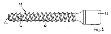
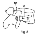
椎骨組織に係止される重要な一群のねじとしてペディクルスクリューが挙げられる。ペディクルスクリューは、ロッドまたは他の脊柱安定装置に取付けるためのねじ頭部と、ねじ切りされたねじ軸とを含む。ねじ切りされたねじ軸は、背側方向から椎弓根を通って堆骨に埋込まれることにより、椎体にめり込む。このように、ペディクルスクリューは脊柱を安定させる構成の一部であり、このため、実質的な機械的負荷を受ける。 An important group of screws locked to vertebral tissue is the pedicle screw. The pedicle screw includes a screw head for attachment to a rod or other spinal stabilizer and a threaded screw shaft. The threaded shaft is threaded into the vertebral body by being embedded in the calculus through the pedicle from the dorsal direction. Thus, the pedicle screw is part of a configuration that stabilizes the spinal column and is therefore subject to substantial mechanical loads.
発明の概要
この発明の目的は、既存のペディクルスクリューおよび対応する脊柱安定方法の欠点を克服する椎弓根係止装置および椎弓根係止装置を係止するシステムを提供することである。
SUMMARY OF THE INVENTION It is an object of the present invention to provide a pedicle locking device and a system for locking a pedicle locking device that overcomes the drawbacks of existing pedicle screws and corresponding spinal stabilization methods.
本発明の第1の局面に従うと、椎弓根係止装置が提供される。椎弓根係止装置は、ペディクルスクリューと同様に用いられるよう具備される。すなわち、装置の遠位部分が椎体へとめり込むように椎弓根を通って背側方向から(但し、概して矢状面に向かってわずかに内側に矢状面に対して角度をなして)堆骨に埋込まれるよう具備される。椎弓根係止装置は椎弓根係止装置本体を含む。椎弓根係止装置本体の近位部分は、脊柱を安定させる整形外科用ロッドまたは他の装置を固定する役割を果たす頭部を有する。このように、椎弓根係止装置本体は、頭部および軸部分を有する。頭部および軸部分は一部品でできていてもよく、または、頭部は多軸接続または他の接続によって軸部分に接続されてもよい。軸部分は、堆骨においてペディクルスクリュー軸(しばしば「ステム」と称される)のように係止可能である。頭部は、たとえば、先行技術のペディクルスクリューの頭部と同様に形成されてもよく、または、新しい脊柱安定システムの仕様に応じて形成されてもよい。頭部の主な必要性として、ロッドもしくは他の脊柱安定装置に直接に取付けられるのに役立つ点、または、ロッド(もしくは他の脊柱安定装置および/もしくは他の中間装置)を取付けることのできる中間装置に取付けられるのに役立つ点が挙げられる。 According to a first aspect of the present invention, a pedicle locking device is provided. The pedicle locking device is provided to be used in the same manner as a pedicle screw. That is, from the dorsal direction through the pedicle so that the distal portion of the device snaps into the vertebral body (but generally at an angle to the sagittal plane slightly inward toward the sagittal plane). It is equipped to be embedded in the skeleton. The pedicle locking device includes a pedicle locking device body. The proximal portion of the pedicle locking device body has a head that serves to secure an orthopedic rod or other device that stabilizes the spine. Thus, the pedicle locking device body has a head and a shaft portion. The head and shaft portion may be made of one piece, or the head may be connected to the shaft portion by a multi-axis connection or other connection. The shaft portion is lockable like a pedicle screw shaft (often referred to as a “stem”) in the calculus. The head may be formed, for example, similar to the head of a prior art pedicle screw or according to the specifications of a new spinal stabilization system. The main need for the head is to help attach directly to a rod or other spinal stabilizer, or an intermediate where a rod (or other spinal stabilizer and / or other intermediate device) can be attached This is useful for being attached to the device.
本発明の第1の局面に従った椎弓根係止装置本体は、椎弓根係止装置本体の近位端から延在する長手方向ボアと、長手方向ボアから外方に向かう、たとえば径方向外側に向かう、1つまたは複数の孔とを有する。 A pedicle locking device body in accordance with the first aspect of the present invention includes a longitudinal bore extending from the proximal end of the pedicle locking device body and outwardly from the longitudinal bore, eg, diameter. With one or more holes going outward in the direction.
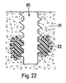
さらに、椎弓根係止装置は、長手方向ボアに挿入可能であるかまたは挿入された液化可能な要素を含み、液化可能な要素は、近位側から当たるエネルギの衝撃によって少なくとも部分的に液化可能であり、こうして、液化した材料が、壁の孔を通って長手方向ボアから流れ出て、硬組織および/または硬組織置換材料の構造へと流れ込むようにする。これにより、液化可能な(好ましくは熱可塑性の)材料が凝固した後、硬組織/硬組織置換材料において、しっかりと嵌合して接続するタイプの係止が達成される。 Further, the pedicle locking device includes a liquefiable element that is insertable or inserted into the longitudinal bore, the liquefiable element being at least partially liquefied by the impact of energy striking from the proximal side. Yes, thus allowing the liquefied material to flow out of the longitudinal bore through the hole in the wall and into the structure of the hard tissue and / or hard tissue replacement material. This achieves a type of locking that fits and connects securely in the hard tissue / hard tissue replacement material after the liquefiable (preferably thermoplastic) material has solidified.
液化可能な要素は単一の一体型要素であってもよい。このような単一の一体型要素は、近位端から遠位端に機械的エネルギを伝達する点で有利であり得る。代替的には、複数の成形片、チップ、フレークなどの複数の液化可能な要素が存在していてもよい。 The liquefiable element may be a single integrated element. Such a single integral element may be advantageous in that it transmits mechanical energy from the proximal end to the distal end. Alternatively, there may be a plurality of liquefiable elements such as a plurality of shaped pieces, chips, flakes and the like.
側方に開口部があるスリーブ要素(この明細書において、スリーブ要素または管要素または被覆要素を参照する場合、これらは、概して、特定の外形に限定することなく、ボアから外部にまでおよぶ開口部を備えた長手方向ボアを有する要素を意味している)における材料を機械的エネルギの衝撃によって液化させ、側方の開口部を用いてスリーブ要素から液化した材料を押出す原理が、たとえば、US7,335,205、US6,921,264、WO2009/055952、WO2009/010247、WO2009/010234、およびPCT出願PCT/CH2009/000138に開示されており、そのすべてが引用によりこの明細書中に援用されている。 Sleeve elements with lateral openings (in this specification, when referring to sleeve elements or tube elements or covering elements, these are generally openings extending from the bore to the exterior, without being limited to a particular profile. The principle of liquefying the material in a mechanical energy impact and extruding the liquefied material from the sleeve element using lateral openings is described, for example, in US Pat. , 335,205, US 6,921,264, WO2009 / 055952, WO2009 / 010247, WO2009 / 010234, and PCT application PCT / CH2009 / 000138, all of which are incorporated herein by reference. Yes.
第1の群の実施例においては、椎弓根係止装置はペディクルスクリューであり、軸がねじ切りされている。 In a first group of embodiments, the pedicle locking device is a pedicle screw and the shaft is threaded.
第1の群の実施例のうちいくつかの実施例においては、ねじ山は一定の外径(ねじ外径)を有し、コア径(谷の径)は遠位側よりも近位側の方がより大きくなっている。たとえば、コア径は、ねじ切りされた区域の全長に沿って徐々に小さくなっていてもよく、または、コア径は、段状の特徴を有するかもしくは他の特徴を有する。他の代替的な実施例においては、コア径は一定である。 In some embodiments of the first group of embodiments, the thread has a constant outer diameter (screw outer diameter) and the core diameter (valley diameter) is more proximal than distal. Is bigger. For example, the core diameter may be gradually reduced along the entire length of the threaded area, or the core diameter may have stepped features or other features. In another alternative embodiment, the core diameter is constant.
第1の群の実施例のうちいくつかの実施例においては、係止は、ねじ山の作用と、硬組織/硬組織置換材料の構造に貫入する液化可能な再凝固した材料の作用との組合せによって達成される。 In some embodiments of the first group of embodiments, the locking is between the action of a thread and the action of a liquefiable resolidified material that penetrates the structure of the hard tissue / hard tissue replacement material. Achieved through a combination.
第2の群の実施例に従うと、椎弓根係止装置の軸はねじ切りされていない。
これらの実施例においては、軸は非円形の断面を有し得る。たとえば、軸はブレード状になるようにやや平たくてもよい。特に、軸は、椎弓根を貫通する場合、椎弓根の形状に従うように横方向よりも長手方向の方がより大きい範囲を有するようなものであってもよい。一例においては、軸は横断面に対して鋭角をなしていてもよく、これにより、遠近軸に対して垂直なより大きな範囲が、(遠近軸に対して垂直な断面において)椎弓根のより大きな範囲の対応方向にほぼ一致する方向に延在することとなる。
According to a second group of embodiments, the axis of the pedicle locking device is not threaded.
In these embodiments, the shaft may have a non-circular cross section. For example, the shaft may be slightly flat so as to have a blade shape. In particular, the axis may be such that when penetrating the pedicle, it has a greater extent in the longitudinal direction than in the lateral direction so as to follow the shape of the pedicle. In one example, the axis may form an acute angle with respect to the transverse plane, so that a larger range perpendicular to the perspective axis is greater than that of the pedicle (in the section perpendicular to the perspective axis). It extends in a direction that substantially coincides with the corresponding direction of the large range.
加えて、非円形の断面は、必要に応じて、ねじり運動に対して付加的な安定性をもたらす可能性がある。 In addition, a non-circular cross-section can provide additional stability to torsional motion if desired.
特別な実施例においては、軸は非円形の断面を有していてもよく、ねじられていてもよい。このようなねじれにより、有効な係止断面が改善される。組織のうち他のより大きな部分が係止に寄与し得る。 In particular embodiments, the shaft may have a non-circular cross section and may be twisted. Such a twist improves the effective locking cross section. Other larger portions of tissue can contribute to the lock.
軸がねじられる場合、概してゼロ以外で最大270°までのねじりが好ましい。というのも、約270°までであれば、椎弓根内における配向の際に、概して、椎弓根内において利用可能な空間を用いることができるのに対して、ねじれがはるかに大きければ、係止装置が椎弓根内で大幅にねじられる可能性があり、このため、軸の最大範囲の寸法を(埋込み軸に対して垂直な断面における)椎弓根のより小さな断面範囲に適合させなければならなくなるからである。より一般的には、椎弓根係止装置の全長にわたるねじれについての好ましい範囲は、10°〜270°であり得る。 When the shaft is twisted, a twist other than zero and up to 270 ° is generally preferred. This is because up to about 270 °, the orientation in the pedicle can generally use the space available in the pedicle, whereas if the twist is much greater, The locking device can be significantly twisted in the pedicle, so that the maximum range dimension of the shaft is adapted to the smaller cross section range of the pedicle (in a cross section perpendicular to the implant axis). Because you have to. More generally, the preferred range for twist over the full length of the pedicle locking device may be between 10 ° and 270 °.
たとえば、軸は、特に約80°〜120°ねじられて約4分の1の螺旋をなしてもよく、これにより、遠位端におけるブレード面が、軸の近位端におけるブレード面に対してほぼ垂直になる。たとえば、ロッドを受ける頭部(または脊柱安定剤を施すための他の手段)は、ブレード面が、軸の近位端においては長手方向に対してほぼ平行に向けられ、かつ、軸の遠位端においては横方向に対してほぼ平行に向けられるように、このねじられた軸に対して相対的に配向されてもよい(方向についてのこれらの語は、脊柱軸を指して局所的に適用されるものと理解されるべきである)。この特別な構成により、軸の断面を過度に制限することなく、椎弓根の比較的小さな横方向延在部がなくても十分に係止する、比較的大きな断面軸を提供することができる。加えて、椎弓根係止装置は、椎体において横方向に延在してもよく、これにより、特にアンカーに作用する角運動量に対して優れた安定性をもたらすようにし得る。この角運動量は、アンカーの遠位端に長手方向(上下)の力をもたらし、患者の体が動いている間に生じることが多い。 For example, the shaft may be twisted, particularly about 80 ° -120 °, to form a quarter spiral, so that the blade surface at the distal end is relative to the blade surface at the proximal end of the shaft. It becomes almost vertical. For example, the head receiving the rod (or other means for applying spinal stabilizers) has a blade face oriented generally parallel to the longitudinal direction at the proximal end of the shaft and distal of the shaft. It may be oriented relative to this twisted axis so that it is oriented substantially parallel to the transverse direction at the ends (these terms for direction apply locally to the spinal axis) Should be understood). This special configuration can provide a relatively large cross-sectional shaft that locks well without excessively limiting the cross-section of the shaft and without a relatively small lateral extension of the pedicle. . In addition, the pedicle locking device may extend laterally in the vertebral body, which may provide excellent stability, particularly with respect to angular momentum acting on the anchor. This angular momentum provides a longitudinal (up and down) force at the distal end of the anchor and often occurs while the patient's body is moving.
軸が円形の断面を有さない第2の群の実施例のうちいくつかの実施例においては、軸は、単なる形状や液化され再度凝固した材料によって得られる係止効果に対して圧入効果を加えるように、わずかに先細にされてもよい。 In some embodiments of the second group of embodiments where the shaft does not have a circular cross-section, the shaft has a press-fit effect against the mere shape or locking effect obtained by liquefied and re-solidified material. It may be slightly tapered to add.
第2の群の実施例のうち、軸が円形断面を有さずやや平たくなっている実施例においては、長手方向ボアから外方に向かう孔は、特に、2つの平坦な側部の各々に開口部を有し得る。小さな側部のうちの少なくとも一方側および/または遠位端に付加的な孔があってもよい。遠位端における付加的な軸孔は手術中には有利であり得る。なぜなら、Kワイヤまたは同様の装置によって挿入中にアンカーを案内することを可能にするからである。このような軸孔は、(軸に対して)中心に配置され得るかまたは中心から外れて配置され得る。「孔径」および「孔深さ」のパラメータに応じて(また、円周に沿った他の孔の対応するパラメータにも関連して)、軸孔は、液化した材料が孔から押出されて組織に押込まれるようなものであってもよく、または、軸孔に流入する液化した材料が、孔出口に達する前に硬化し、これにより、液化可能な再凝固材料のプラグが作り出されるようなものであってもよい。 In the second group of embodiments, in which the shaft does not have a circular cross-section and is somewhat flat, the outward holes from the longitudinal bore are in particular on each of the two flat sides. It may have an opening. There may be additional holes on at least one side and / or the distal end of the small side. An additional axial hole at the distal end may be advantageous during surgery. This is because it allows the anchor to be guided during insertion by a K-wire or similar device. Such a shaft hole can be centrally located (relative to the axis) or off-center. Depending on the "hole diameter" and "hole depth" parameters (and also in relation to the corresponding parameters of other holes along the circumference), the axial hole is a structure in which liquefied material is extruded from the hole. Or the liquefied material flowing into the shaft hole hardens before reaching the hole outlet, thereby creating a plug of reconsolidated material that can be liquefied. It may be a thing.
本発明はまた、図を参照しつつ説明された方法のうち少なくとも1つの方法ステップを含む方法によって、第2の局面に従った椎弓根係止装置を埋込む方法に関する。特に、椎弓根係止装置を係止する方法は、上述のタイプの椎弓根係止装置の椎弓根係止装置本体を堆骨に挿入するステップと、エネルギを液化可能な要素に結合しつつ、液化可能な要素を遠位側に向かって長手方向ボア内に押込むステップと、これにより、液化可能な要素の部分を液化させ、少なくとも1つの孔から押出して骨組織に押込むステップと、液化された部分を再度凝固させて付加的なアンカーを設けるステップとを含む。 The invention also relates to a method of implanting a pedicle locking device according to the second aspect by a method comprising at least one method step of the method described with reference to the figures. In particular, a method of locking a pedicle locking device includes inserting a pedicle locking device body of a pedicle locking device of the type described above into a calculus and coupling energy to a liquefiable element. However, pushing the liquefiable element distally into the longitudinal bore and thereby liquefying a portion of the liquefiable element and pushing it out of at least one hole into the bone tissue And re-solidifying the liquefied portion to provide additional anchors.
椎弓根係止装置が完全に円筒形ではない外形を有しているが、ねじ山などの外側保持構造を有するかまたは螺旋状にねじられている場合、椎弓根係止装置はこのような構造によって係止される。たとえば、自動ロックが十分でない場合にこの係止に必要とされる可能性のある付加的な回転防止保護部が、必然的に脊柱安定ロッドなどによって設けられてもよい。状況に応じて、外科医は、付加的な係止強度を確保するために液化可能な要素を自由に用いることができてもよく、または、係止強度が十分であると感じた場合には液化可能な材料を用いない選択をしてもよい。 If the pedicle locking device has a profile that is not completely cylindrical, but has an outer retaining structure such as a thread or is twisted helically, the pedicle locking device is It is locked by a simple structure. For example, additional anti-rotation protection may be provided, such as by a spinal stabilization rod, that may be required for this locking if automatic locking is not sufficient. Depending on the situation, the surgeon may be free to use liquefiable elements to ensure additional locking strength, or liquefy if the locking strength feels sufficient You may choose not to use possible materials.
好ましい実施例においては、椎弓根係止装置は、本発明の第1の局面の実施例に従った装置である。 In a preferred embodiment, the pedicle locking device is a device according to an embodiment of the first aspect of the present invention.
近位端から延在する非円形の軸部分と、長手方向ボアから外方に向かう少なくとも1つの孔と(必要に応じて、軸部分の近位側の頭部と)を備えた上述のタイプの係止装置は、また、ペディクルスクリュー以外の用途のために設けられてもよい。このような係止装置の軸は、任意には、上述の椎弓根係止装置のように、たとえば90°だけ螺旋状にねじられてもよい。 The type described above with a non-circular shaft portion extending from the proximal end and at least one hole outward from the longitudinal bore (optionally a head on the proximal side of the shaft portion). This locking device may also be provided for applications other than pedicle screws. The shaft of such a locking device may optionally be helically twisted, for example by 90 °, like the pedicle locking device described above.
特に、このような係止装置は、骨折、特に、骨組織が時として比較的弱く、従来の外科手術用ねじを係止するのが困難である可能性のある関節付近の骨折、の治療用のアンカーとして用いられてもよい。 In particular, such locking devices are particularly useful for the treatment of fractures, especially fractures near joints where bone tissue is sometimes relatively weak and it may be difficult to lock conventional surgical screws. It may be used as an anchor.
比較的弱い骨組織において熱可塑性材料を用いてTiインプラントを係止する利点を調べるために、計算および実験を行なった。矩形の断面を備えたTiコアと、熱可塑性材料とを含むアンカーについて有限要素計算を行った。この熱可塑性材料は、機械的エネルギによって液化され、周囲組織の構造に押込まれ、再凝固した後にアンカーを形成するものである。これらの計算により、ペディクルスクリューの係止の例に対して、応力が大幅に低下することが明らかになった。フォン・ミーゼス歪みは、円形断面のアンカーの場合の74.5%からH字型断面のアンカーの場合の87%の範囲で低減されることを示した(M. Rollinghoff およびS. Saladin(ETH Zurich Master Thesis))。この発見は、人の踵骨についての生化学的実験によって実験的に確認された。これについて、シャンツ(Schanz)ねじをピン状のチタンアンカー(コア径:4mm)と比較した。ピン状のチタンアンカーは、0.5mmのPLDLA70/30によってコーティングされ、機械的振動によって係止されて、PLDLAを少なくとも部分的に液化させ、海綿骨の構造に押込んで、そこに係止をもたらした。引抜き力は、海綿骨の硬度(押込抵抗)の関数として(2mmのインデンタにわたって)測定された。コーティングされたTiアンカーの引抜き力は、シャンツねじの引抜き力よりも係数2〜4だけ著しく優れており、この差は弱い骨組織にとっては大きなものであった。 Calculations and experiments were performed to investigate the benefits of locking Ti implants with thermoplastic materials in relatively weak bone tissue. Finite element calculations were performed on anchors including a Ti core with a rectangular cross section and a thermoplastic material. This thermoplastic material is liquefied by mechanical energy, pushed into the surrounding tissue structure, and re-solidifies to form an anchor. These calculations revealed that the stress was significantly reduced for the pedicle screw locking example. Von Mises distortion has been shown to be reduced in the range of 74.5% for circular cross-section anchors to 87% for H-shaped cross-section anchors (M. Rollinghoff and S. Saladin (ETH Zurich Master Thesis)). This finding was confirmed experimentally by biochemical experiments on human ribs. In this regard, a Schanz screw was compared with a pin-shaped titanium anchor (core diameter: 4 mm). Pinned titanium anchors are coated with 0.5 mm PLDLA 70/30 and locked by mechanical vibration to at least partially liquefy PLDLA and push into the cancellous bone structure, resulting in locking there It was. The withdrawal force was measured (over a 2 mm indenter) as a function of cancellous bone hardness (indentation resistance). The pulling force of the coated Ti anchor was significantly better by a factor of 2 to 4 than the pulling force of the Shantz screw, and this difference was significant for weak bone tissue.
また、引抜き破壊測定は、死亡した骨減少症の人の椎骨から図3〜図5に示されるタイプのペディクルスクリューと、比較のために、同じ形状を有するが熱可塑性材料が孔から径方向に押出されていないペディクルスクリューとを用いて行われた。永久転位に対する破壊力は、平均で124%だけ高くなることが示された。さらに重要な発見としては、弾性挙動からのずれとして観察されたペディクルスクリューの緩み挙動を熱可塑性材料の係止を用いて大幅に改善したことであった。 In addition, the pull-out fracture measurement was carried out by comparing the pedicle screw of the type shown in FIGS. 3 to 5 with the pedicle screw of the type shown in FIGS. And a pedicle screw that was not extruded. It has been shown that the destructive force for permanent dislocations is on average 124% higher. A further important finding was that the loosening behavior of the pedicle screw, which was observed as a deviation from the elastic behavior, was greatly improved using the locking of the thermoplastic material.
第1または第2の群の実施例であり得る実施例においては、液化可能な要素の材料は、たとえば、治癒または再生を促進するかまたはX線可視性を促進させるために、付加的な物質を含有し得る。たとえば、付加的な物質は、成長因子、抗生物質、炎症阻害剤または緩衝剤であってもよい。より特定的には、付加的な物質は、治癒、特に成長、分化および/または再生を促進する薬剤、たとえば、骨形成タンパク質ファミリ(特に、BMP2、6、7、特定の応用例に対してはBMP12、13)、インシュリン成長因子(たとえばIGF1)、血小板由来成長因子(PDGF)、成長および分化因子(たとえばGDF5)などの成長および/または分化因子、および、それらの組合せ、等のタンパク質薬剤、ならびに/または、場合によってはタンパク質薬剤と併用される、小さな分子(たとえばビスホスホネート)を含む非タンパク質薬剤を含む他の薬剤などであり得る。 In an embodiment that may be the first or second group of embodiments, the material of the liquefiable element is an additional substance, for example to promote healing or regeneration or to promote X-ray visibility. May be contained. For example, the additional substance may be a growth factor, antibiotic, inflammation inhibitor or buffer. More specifically, the additional substance may be an agent that promotes healing, especially growth, differentiation and / or regeneration, such as the bone morphogenetic protein family (particularly BMP2, 6, 7, for certain applications). Protein drugs such as BMP12,13), growth and / or differentiation factors such as insulin growth factor (eg IGF1), platelet derived growth factor (PDGF), growth and differentiation factor (eg GDF5), and combinations thereof, and And / or other drugs, including non-protein drugs, including small molecules (eg, bisphosphonates), possibly in combination with protein drugs.
第1または第2の群の実施例であり得る実施例においては、液化可能な要素は、チキソトロープ性を有する(ポリマーセメントまたは他の水硬性セメントなどの)水硬性セメントであってもよい。このような実施例は、液化可能な材料が成長因子などの付加的な物質を含む実施例であり得る。係止装置の特殊例として、大腿骨の狭細部の骨折を治療するための装置が挙げられる。この場合、この装置は最先端技術を用いた釘と置換えることができる。この釘は、たとえばUS3,025,853に開示されるような位置および向きで、大腿骨の軸からその頭部に貫入し、骨折した狭細部を貫通する。 In embodiments that may be the first or second group of embodiments, the liquefiable element may be a hydraulic cement (such as a polymer cement or other hydraulic cement) that has thixotropic properties. Such an embodiment may be an embodiment in which the liquefiable material includes additional substances such as growth factors. A special example of a locking device is a device for treating a narrow fracture of the femur. In this case, the device can be replaced with a nail using state-of-the-art technology. The nail penetrates into the head from the femoral shaft, for example in the position and orientation as disclosed in US Pat. No. 3,025,853, and penetrates the narrow fracture details.
より一般的には、このような係止装置は、人もしくは動物の骨への係止が困難である状況、ならびに/または、幾何学的制限および/もしくは課されるべき機械的負荷によって、非円形の断面や、たとえばねじられた軸でさえも有利になる状況において、ねじを安定させるものとして用いられてもよい。 More generally, such locking devices are not suitable for situations where locking to human or animal bones is difficult and / or due to geometric limitations and / or mechanical loads to be imposed. In situations where a circular cross-section or even a twisted shaft, for example, would be advantageous, it may be used as a screw stabilizer.
実施例においては、係止装置本体は、長手方向ボアから外方に向かう複数の孔を含み、係止装置は方向付け構造を含む。この方向付け構造は、これらのそれぞれの孔に液化可能な材料のそれぞれの部分を方向付けるよう、長手方向ボアの長手方向軸に対して角度を付けて構造化されている。「角度を付けて構成される(Structured angularly)」または「方位角で(azimuthally)」とは、構造が周辺部に沿って一定ではなく、方位角の関数として変化することを意味している。この場合、方向付け構造は、長手方向ボアの断面内の構造である。すなわち、たとえば、長手方向ボアが円形の断面を有している場合、方向付け構造の径方向位置は少なくとも部分的にボアの半径内にある。 In an embodiment, the locking device body includes a plurality of holes outward from the longitudinal bore, and the locking device includes an orientation structure. The orientation structure is structured at an angle with respect to the longitudinal axis of the longitudinal bore so as to direct the respective portions of the liquefiable material into these respective holes. “Structured angularly” or “azimuthally” means that the structure is not constant along the periphery but changes as a function of azimuth. In this case, the orientation structure is a structure in the cross section of the longitudinal bore. That is, for example, if the longitudinal bore has a circular cross-section, the radial position of the directing structure is at least partially within the radius of the bore.
さらに、方向付け構造は停止面によって形成されており、液化可能な要素の遠位端が液化中にこの停止面に押当てられる。液化可能な要素のための遠位側の停止面は、たとえば、遠位側に向かって長手方向の開口部を閉じ得るか、または、近位部分と比べて、長手方向の開口部の断面のうち遠位部分を少なくとも実質的に(たとえば、少なくとも50%)小さくし得る。方向付け構造から遠位側に延在する長手方向開口部の遠位部分の任意の残りの断面は、たとえば、中心の案内部分としての役割を果たし得るか、または、遠位孔としての役割を果たし得る。液化した材料の部分は、被覆要素の壁の孔に加えて、この遠位孔を通って押出されてもよい。停止面は係止装置本体によって形成されてもよい。代替的には、方向付け構造は、その場で挿入可能な挿入要素の方向付け構造である。 Furthermore, the directing structure is formed by a stop surface, the distal end of the liquefiable element being pressed against this stop surface during liquefaction. A distal stop surface for the liquefiable element can, for example, close the longitudinal opening towards the distal side, or in a cross section of the longitudinal opening relative to the proximal portion. The distal portion may be at least substantially (eg, at least 50%) smaller. Any remaining cross-section of the distal portion of the longitudinal opening extending distally from the directing structure may serve, for example, as a central guide portion or as a distal hole It can be fulfilled. A portion of the liquefied material may be extruded through this distal hole in addition to the hole in the wall of the covering element. The stop surface may be formed by the locking device body. Alternatively, the orientation structure is an orientation structure of an insertable element that can be inserted in situ.
本発明のさらなる第2の局面に従うと、インプラントの挿入のための硬組織および/または硬組織置換材料を補強する方法、ならびにこのような補強方法を含む埋込み方法が提供される。インプラントは、埋込み後に硬組織および/または硬組織置換材料に係止される骨内領域を有する。本発明の第4の局面に用いられる外形体の一部は、その外形が、本質的に、インプラントの骨内領域のうち少なくとも一部の外形に一致する。 According to a further second aspect of the present invention, there is provided a method of reinforcing hard tissue and / or hard tissue replacement material for insertion of an implant, and an embedding method comprising such a reinforcing method. The implant has an intraosseous region that is locked to hard tissue and / or hard tissue replacement material after implantation. The part of the outer body used in the fourth aspect of the present invention essentially matches the outer shape of at least a part of the intra-osseous region of the implant.
具体的には、インプラントは雄ねじを有してもよく、外形体は、外形体の延在部が任意にはインプラントの対応する延在部よりも好ましくはほんのわずかに小さい可能性がある点を除いては、(ねじピッチなどの)同じねじパラメータおよび同じ寸法を有する雄ねじを備える。また、ねじ山の谷の径をインプラントと外形体との間で本質的に同一にすることもできるのに対して、外形体のねじ山のねじ外径はインプラントのねじ山のねじ外径よりも小さい。 In particular, the implant may have external threads, and the profile may be such that the extension of the profile can optionally be only slightly smaller than the corresponding extension of the implant. Otherwise, it has male threads with the same thread parameters (such as thread pitch) and the same dimensions. The thread valley diameter can also be made essentially the same between the implant and the outer body, whereas the outer thread diameter of the outer thread is larger than the outer thread diameter of the implant thread. Is also small.
外形体はさらに、外形体の近位端から遠位側に達する長手方向ボアを含む。少なくとも1つの孔は長手方向ボアを囲む壁にある。液化可能な要素は長手方向ボアに差込まれてもよく、またはその内部に存在する。外形体はさらに、液化可能な要素のための停止面を含み、この停止面に対して液化可能な要素の遠位端が押当てられてもよい。このように、外形体は、上述のタイプの被覆要素であり、本発明の第1の局面の実施例に従って任意に形成されてもよい(が、必ずしもそうである必要はない)。場合によっては、外形体に加えて、挿入要素があってもよい。 The profile further includes a longitudinal bore that extends distally from the proximal end of the profile. At least one hole is in the wall surrounding the longitudinal bore. The liquefiable element may be plugged into or present within the longitudinal bore. The profile further includes a stop surface for the liquefiable element, against which the distal end of the liquefiable element may be pressed. Thus, the profile is a covering element of the type described above and may optionally be formed according to the embodiment of the first aspect of the present invention (but not necessarily so). In some cases, there may be an insertion element in addition to the outer shape.
第2の局面に従った方法は、以下の付加的なステップを特徴とする。すなわち、
− 硬組織および/または硬組織置換材料における開口部または隙間に外形体を差込むステップと、
− 遠位側の停止面に液化可能な要素を押当てつつ、エネルギをこれに当てて、液化可能な要素の材料を液化させ、少なくとも1つの孔を通過させ、インプラントが係止されることとなる骨組織または他の硬組織もしくは硬組織置換材料の構造に押込み、予め形作られた補強領域をもたらすステップと、
− 外形体を除去するステップと、
− 予め形作られた補強領域の輪郭がインプラントの外形と協働してインプラントを不所望に移動しないよう固定するように、インプラントを挿入するステップとを含む。
The method according to the second aspect is characterized by the following additional steps: That is,
-Inserting the outer body into the opening or gap in the hard tissue and / or hard tissue replacement material;
-Pressing the liquefiable element against the distal stop surface and applying energy to it to liquefy the material of the liquefiable element, passing through at least one hole and locking the implant; Intruding into the structure of bone tissue or other hard tissue or hard tissue replacement material, resulting in a pre-shaped reinforcement region;
-Removing the outline;
Inserting the implant such that the contour of the pre-shaped reinforcement region cooperates with the contour of the implant to secure the implant from undesirably moving.
外形体を除去するステップの前に、他のステップが行われてもよい。たとえば、外形体は試用インプラントと置換えられてもよく、位置および/または他の条件をX線(など)で制御してもよい。補強用の外形体の機能と試用インプラントの機能とをこのように組合せることによって、本発明の局面に従った補強プロセスでは、補強なしの先行技術の方法と比べて、余分のステップが数個追加されるだけである。 Other steps may be performed before the step of removing the outline. For example, the profile may be replaced with a trial implant and the position and / or other conditions may be controlled with x-rays (etc.). By combining the function of the reinforcing profile and the function of the trial implant in this way, the reinforcement process according to aspects of the invention has several extra steps compared to the prior art methods without reinforcement. It is only added.
概して、外形体の断面の外形が本質的にインプラントの骨内領域のうち少なくとも一部の外形に一致するという特徴は、上記断面におけるすべての寸法が等しいことを示唆するものではない。むしろ、外形体の寸法は異なっていてもよく、特により小さくてもよい。しかしながら、この特徴は、インプラントの形状が外形体を用いて成形された空間に概ね嵌まることを示唆している。というのも、インプラントの各々の外形特徴(すなわち、円筒形の基本的形状などの凸状の基本体から突出る特徴)について、外形体の対応する特徴が存在し、その外形特徴が互いに対応する位置関係にあるからである。インプラントが雄ねじを含む場合、これは、外形体が、同じねじピッチ(この場合、インプラントの多条ねじ、およびこれに応じて外形体の多条ねじは除外されない)を有する雄ねじをも含むことを示唆する。インプラントが複数の軸方向舌状部を含む場合、規定された方位角では、外形体は、同じ方位角などで、対応する数の軸方向舌状部を含むこととなる。 In general, the feature that the cross-sectional profile of the profile essentially matches the profile of at least some of the intra-osseous regions of the implant does not imply that all dimensions in the cross-section are equal. Rather, the dimensions of the outer body may be different and especially smaller. However, this feature suggests that the shape of the implant generally fits in the space formed using the outer shape. This is because, for each external feature of the implant (that is, a feature protruding from a convex basic body such as a basic cylindrical shape), there is a corresponding feature of the external body, and the external features correspond to each other. This is because of the positional relationship. If the implant includes external threads, this means that the profile also includes external threads having the same thread pitch (in this case, the multiple threads of the implant and, accordingly, the multiple threads of the profile are not excluded) Suggest. If the implant includes a plurality of axial tongues, at a defined azimuth angle, the profile will include a corresponding number of axial tongues, such as at the same azimuth angle.
外形体がインプラントよりも小さい場合、その寸法は好ましくはほんのわずかに変化することとなる。たとえば、インプラントがねじ山を有する場合、ねじ山の谷の径は、たとえば最大で5%小さくなり、好ましくは等しくなる。外形体ねじのねじ山深さは、好ましくは、インプラントのねじ山深さのねじ山深さのうち少なくとも50%である。 If the profile is smaller than the implant, its dimensions will preferably change only slightly. For example, if the implant has threads, the diameter of the thread valley is, for example, at most 5% smaller and preferably equal. The thread depth of the outer body screw is preferably at least 50% of the thread depth of the implant thread depth.
しばしば、骨ねじなどの先行技術のインプラント係止では、特に海綿質骨組織が係止の安定性にほとんど寄付しなかったという問題に直面した。これは、海綿質骨組織に脆い傾向があり、引裂き力に対する抵抗に寄与し得る骨梁がほんのわずかしかない可能性があるからである。組織がたとえば骨梁内の構造を満たす熱可塑性材料によって補強される場合、この問題は少なくとも部分的に解決され得る。しかしながら、熱可塑性材料が十分に延性を有して頑丈である場合、セルフタッピングねじまたは別個のタッパーを補強された組織にねじ込むのに相当な力が必要となる。多くの場合、補強材料およびこの補強材料に埋込まれた少数の骨梁を含む補強材料体が、海綿質骨組織から外れ、全体が組織内で回転する危険がある。 Often, prior art implant locking, such as bone screws, faced the problem that especially cancellous bone tissue contributed little to locking stability. This is because cancellous bone tissue tends to be brittle and there may be only a few trabeculae that can contribute to resistance to tearing forces. This problem can be solved at least in part if the tissue is reinforced by, for example, a thermoplastic material that fills the structure within the trabecular bone. However, if the thermoplastic material is sufficiently ductile and sturdy, considerable force is required to screw the self-tapping screw or a separate tapper into the reinforced tissue. In many cases, there is a risk that the reinforcing material body including the reinforcing material and a small number of trabeculae embedded in the reinforcing material may come off the cancellous bone tissue and rotate entirely within the tissue.
本発明の第2の局面に従った方策は、対照的に、比較的大きなねじ山深さを有するねじなどの顕著な外形特徴を備えたインプラントでさえも、挿入中にさほど大きな力を加える必要なしに、力に対して比較的に非常に安定しかつ抵抗性のある補強された組織/材料に挿入できるようにする。 The strategy according to the second aspect of the present invention, in contrast, requires that much force be applied during insertion, even for implants with significant profile features such as screws having a relatively large thread depth. Without being able to be inserted into a reinforced tissue / material that is relatively very stable and resistant to forces.
本発明の第2の局面に従った方法の実施例は、後のステップで挿入されるべきインプラントのために、硬組織および/または硬組織置換材料に係止された補強領域を所望の形状に成形するものと見なされてもよい。 An embodiment of a method according to the second aspect of the present invention provides a desired shape of a reinforced region locked to hard tissue and / or hard tissue replacement material for an implant to be inserted in a later step. It may be considered to be molded.
このため、材料の除去および/または変形を含む後続の形成ステップは不要となる(但し、本発明の第2の局面では付加的な形成ステップは除外されない)。本発明の第2の局面に従った方策は、緩やかであるが有効な補強を可能にし得る。 This eliminates the need for subsequent forming steps including material removal and / or deformation (although additional forming steps are not excluded in the second aspect of the invention). The strategy according to the second aspect of the present invention may allow a modest but effective reinforcement.
実施例においては、外形体は、長手方向ボアのまわりの壁に3〜5個の孔を有し、これらの孔がほぼ等しい軸方向位置にくるように選択される。たとえば、外形体は、長手方向ボアのまわりの壁にちょうど4つの孔を有し、これらの孔がほぼ等しい軸方向位置にくるように選択されてもよい。 In an embodiment, the profile has 3 to 5 holes in the wall around the longitudinal bore and is selected so that these holes are in approximately equal axial positions. For example, the profile may be selected so that it has exactly four holes in the wall around the longitudinal bore and these holes are in approximately equal axial positions.
実施例においては、外形体は、液化可能な材料/液化した材料のさまざまな部分を、それぞれ、さまざまな開口部に方向付けるために、角度を付けて構造化された方向付け構造を長手方向ボアの遠位側に有していてもよい。 In an embodiment, the profile includes an angled structured directing structure to direct the various portions of the liquefiable material / liquefied material to the various openings, respectively. You may have in the distal side of.
実施例においては、外形体は、少なくともペディクルスクリューの骨内部分の断面に本質的に一致する外形を有する。方法は、外形体を本質的に背側の方向から堆骨に、より特定的には椎弓根に差込むステップを含む。補強後に埋込まれるインプラントはペディクルスクリューである。 In an embodiment, the profile has a profile that essentially matches at least the cross-section of the intra-bone portion of the pedicle screw. The method includes the step of plugging the profile from the essentially dorsal direction into the calculus, more particularly into the pedicle. The implant that is implanted after reinforcement is a pedicle screw.
本発明の第2の局面に従った埋込みを実行するための部品のキットは、外形体およびインプラント(たとえば、ペディクルスクリュー)を含む。部品キットは液化可能な要素をさらに含み得る。 A kit of parts for performing implantation according to the second aspect of the present invention includes a profile and an implant (eg, a pedicle screw). The component kit can further include a liquefiable element.
本発明の第3の局面に従うと、外科手術用ねじなどの係止装置が提供される。係止装置は係止装置本体を含み、係止装置本体は、係止装置本体の近位端から延在する長手方向ボアと、長手方向ボアから外方に向かう、たとえば径方向外方に向かう、1つまたは複数の孔とを有する。係止装置はさらに、流動可能な状態から流動不可能な状態にすることのできる材料を含み、この材料は、たとえば、熱可塑性であるか、または、チキソトロープ性を有するかもしくは有さない水硬性セメントである。材料が熱可塑性である場合、流動可能な状態から流動不可能な状態にするステップは、単に、予め(十分または部分的に)溶解された材料を冷却させるステップを含んでいてもよい。材料がセメントである場合、流動可能な状態から流動不可能な状態にするステップは、セメントを硬化させるステップを含み得る。材料がチキソトロピー性材料である場合、流動可能な状態から流動不可能な状態にするステップは、剪断応力の源を停止させて粘性を高めるステップを含み得る。 According to a third aspect of the present invention, a locking device such as a surgical screw is provided. The locking device includes a locking device body, the locking device body extending from the proximal end of the locking device body, and outwardly from the longitudinal bore, eg, radially outward. One or more holes. The locking device further includes a material that can be made from a flowable state to a non-flowable state, which material is, for example, thermoplastic or hydraulic with or without thixotropic properties. Cement. If the material is thermoplastic, the step of making it flowable to non-flowable may simply comprise allowing the previously (fully or partially) dissolved material to cool. When the material is cement, the step of bringing the flowable state into the non-flowable state may include hardening the cement. If the material is a thixotropic material, bringing the flowable state to the nonflowable state may include stopping the source of shear stress to increase the viscosity.
この局面に従うと、材料は付加的な物質をさらに含む。この付加的な物質は、治癒、特に成長、分化および/または再生を促進する薬剤、たとえば、骨形成タンパク質ファミリ(BMP2、6、7;12、13)/形質転換成長因子ベータファミリ、インシュリン成長因子(たとえばIGF1)、血小板由来成長因子(PDGF)、成長および分化因子(たとえばGDF5)などの成長および/または分化因子、および、それらの組合せ、等のタンパク質薬剤、ならびに/または、場合によってはタンパク質薬剤と併用される、小さな分子(たとえばビスホスホネート)を含む非タンパク質薬剤を含む他の薬剤などであり得る。 According to this aspect, the material further comprises additional substances. This additional substance may be an agent that promotes healing, especially growth, differentiation and / or regeneration, such as the bone morphogenetic protein family (BMP2, 6, 7; 12, 13) / transforming growth factor beta family, insulin growth factor Protein drugs such as growth and / or differentiation factors such as (eg IGF1), platelet derived growth factor (PDGF), growth and differentiation factors (eg GDF5), and combinations thereof, and / or protein drugs in some cases Other drugs, including non-protein drugs, including small molecules (eg, bisphosphonates), etc.
係止装置本体は、埋込み条件下では液化できない材料でできている。係止装置本体は、金属、セラミック、埋込み条件下では液化しない(場合によっては強化された)プラスチック、または、他の好適な生体適合性材料でできていてもよい。さらに、係止装置本体は、好ましくは、係止構造、特にねじを有する。特に、係止装置本体は外科手術用ねじ、特にペディクルスクリュー、であってもよい。 The locking device body is made of a material that cannot be liquefied under embedded conditions. The locking device body may be made of metal, ceramic, plastic that does not liquefy (possibly reinforced) under embedded conditions, or other suitable biocompatible material. Furthermore, the locking device body preferably has a locking structure, in particular a screw. In particular, the locking device body may be a surgical screw, in particular a pedicle screw.
第3の局面は、本発明の第1の局面(特に第1の群の実施例)と組合されてもよい。
こうして、第3の局面は、治癒を促進する薬剤を含む材料を用いて外科手術用ねじ(または同様の係止装置)を提供することを提案している。この材料は、開口部から押出されて、長手方向ボアから外方向に向かい、周囲の組織、特に海綿質骨組織に押込むことができる。このように、第3の局面に従った方法/装置により、外科手術用ねじの機能を、治癒促進薬剤を骨組織に直接投入するステップと組合せることが容易に実現可能となる。開口部から押出すことのできる材料は、付加的な係止効果を有し、特に、緩みの挙動を実質的に改善させ得る。
The third aspect may be combined with the first aspect of the invention (particularly the first group of examples).
Thus, the third aspect proposes to provide a surgical screw (or similar locking device) using a material that includes an agent that promotes healing. This material can be extruded from the opening and outward from the longitudinal bore and pushed into the surrounding tissue, particularly cancellous bone tissue. Thus, the method / device according to the third aspect makes it easy to combine the function of the surgical screw with the step of directly injecting the healing-promoting agent into the bone tissue. The material that can be extruded from the opening has an additional locking effect, in particular it can substantially improve the loosening behavior.
付加的な物質が埋込まれ得る特別等級の(基質)材料は、再吸収可能および/または骨伝導性の水硬性セメントである。特別等級のセメントは、たとえば、水と混合されたCa4(PO4)2OおよびCaHPO4粉末に基づいたリン酸カルシウムセメントである。このような物質は生理学的条件で硬化し得る。リン酸カルシウムセメントは人体内でのイオン交換によって硬化し得る。室温では非硬化相がいくらか安定するが体温では急速に硬化するリン酸カルシウムセメントが存在する。 A special grade (matrix) material in which additional substances can be embedded is a resorbable and / or osteoconductive hydraulic cement. A special grade cement is, for example, a calcium phosphate cement based on Ca 4 (PO 4 ) 2 O and CaHPO 4 powder mixed with water. Such materials can be cured at physiological conditions. Calcium phosphate cement can be hardened by ion exchange in the human body. There is a calcium phosphate cement that is somewhat stable at room temperature in the uncured phase but rapidly cures at body temperature.
好適なリン酸カルシウムセメントの具体例として、Synthesによる「ChronOS」および「Norian」が挙げられる。 Specific examples of suitable calcium phosphate cements include “ChronOS” and “Norian” by Synthes.
さらなる例として、PMMAセメントのような再吸収不可能なセメントが挙げられる。
治癒を促進する薬剤に加えて、当該材料はポリマーおよび/またはヒドロゲルを含んでいてもよい。
A further example is a non-resorbable cement such as PMMA cement.
In addition to an agent that promotes healing, the material may include a polymer and / or a hydrogel.
(基質)材料が水硬性セメントである場合、機械的振動などの機械的エネルギが材料に当たり、材料が開口部から押出される。特に、チキソトロピーの作用は粘性の低下を助け得るものであり、このため、近位側から材料に作用する力が弱くても、開口部から材料を押出すことができる。 When the (substrate) material is hydraulic cement, mechanical energy, such as mechanical vibrations, strikes the material and the material is extruded from the opening. In particular, the action of thixotropy can help reduce the viscosity, so that the material can be extruded from the opening even if the force acting on the material from the proximal side is weak.
付加的な物質が埋込まれ得る他の特別等級の(基質)材料は、以下に述べる再吸収可能なポリマーなどの再吸収可能な熱可塑性ポリマーである。さらに、好適な例として、
− 1つ以上の水硬性セメント;
− 1つ以上の、たとえば、再吸収可能なポリマー;
− 1つ以上のヒドロゲル、のいずれかの組合せの混合物が挙げられる。
Other special grade (substrate) materials in which additional substances can be embedded are resorbable thermoplastic polymers such as the resorbable polymers described below. Furthermore, as a suitable example,
-One or more hydraulic cements;
One or more, eg resorbable polymers;
-Mixtures of any combination of one or more hydrogels.
先行技術に従うと、損傷した骨組織部分は、(成長因子を含み得る)骨セメントによって孔などを塞ぐことによって治療される。これとは対照的に、本発明の第6の局面に従った方策は、より的が絞られた治療を可能にする。この場合、薬剤は、開口部から押出されることによって骨組織の内部に直接投与され、骨組織内部により密着し、骨組織以外の組織が薬剤に晒されるのをより少なくするかまたはまったく晒されないようにする。 According to the prior art, damaged bone tissue portions are treated by plugging holes or the like with bone cement (which may include growth factors). In contrast, the strategy according to the sixth aspect of the present invention allows a more targeted treatment. In this case, the drug is administered directly into the bone tissue by being pushed out of the opening, is more closely adhered to the bone tissue, and less or no tissue other than the bone tissue is exposed to the drug. Like that.
− 骨成長因子(または、特に上述したタイプの臨床効果を有する他の付加的な物質)のさらなる使用は以下のとおりである。第1のステップにおいて、骨成長因子(または他の付加的な物質)を含む水硬性セメントが、長手方向ボアおよび当該ボアから外方に向かう1つ以上の孔を有するタイプの装置本体の長手方向ボアから押出される。 -Further use of bone growth factors (or in particular other additional substances with clinical effects of the type mentioned above) are as follows. In a first step, a hydraulic cement containing bone growth factor (or other additional material) is longitudinal in the longitudinal direction of a device body of the type having a longitudinal bore and one or more holes outwardly from the bore. Extruded from the bore.
− 第2の次のステップにおいて、熱可塑性要素が、機械的エネルギの衝撃によって少なくとも部分的に液化され、液化された部分が、水硬性セメントを押出す孔から押出される。 -In a second next step, the thermoplastic element is at least partially liquefied by the impact of mechanical energy, and the liquefied part is extruded from a hole through which the hydraulic cement is extruded.
この一連の方法ステップは、補強または係止のために熱可塑性材料を用いることを特徴とする本発明の如何なる局面において用いられてもよく、治癒を促進する薬剤を含む(基質)材料としての水硬性セメントを特徴とする本発明の如何なる局面において用いられてもよく、代替的には、この明細書中に記載される他の局面とは無関係に適用されてもよく、以下の目的/効果を有する。 This series of method steps may be used in any aspect of the invention characterized by using a thermoplastic material for reinforcement or locking, with water as the (substrate) material containing the agent that promotes healing. It may be used in any aspect of the present invention characterized by hard cement, and may alternatively be applied independently of other aspects described herein, and has the following objects / effects: Have.
− 治癒プロセスの促進、骨密度の向上。
− 即時の安定化、早期の緩みの防止。これにより、インプラントの骨硬化、たとえばオッセオインテグレーションが機械的に防止されることとなる。
-Accelerate the healing process and increase bone density.
-Immediate stabilization and prevention of early loosening. This mechanically prevents the bone hardening of the implant, for example, osseointegration.
ポリマーが急冷され、ポリマーの熱容量および熱伝導性が水性環境の熱容量および熱伝導性よりもはるかに低いので、この手順によっては、セメント内の有効成分に予想され得る熱損傷はなくなるだろう。 Because the polymer is quenched and the heat capacity and thermal conductivity of the polymer is much lower than the heat capacity and thermal conductivity of the aqueous environment, this procedure will eliminate the thermal damage that can be expected of the active ingredients in the cement.
上述の局面に加えて、本発明は以下の付加的な局面を特徴とする。
− 本体の近位端から延在する長手方向ボアと、当該長手方向ボアから外方に向かう1つまたは複数の孔とを有する本体の使用、ならびに、たとえば係止、薬剤送達および/または他の目的で、水硬性セメントを骨組織に投与するために、チキソトロピー効果により粘性を低下させる機械的振動。
In addition to the aspects described above, the present invention is characterized by the following additional aspects.
The use of a body having a longitudinal bore extending from the proximal end of the body and one or more holes outwardly from the longitudinal bore, and for example locking, drug delivery and / or other For the purpose of applying hydraulic cement to bone tissue, mechanical vibration that reduces the viscosity by thixotropic effect.
− たとえば不均質混合物を組織に投与できるように、たとえば不均質混合物の粘性に影響を及ぼすために、たとえば、本体の近位端から延在する長手方向ボアと、当該長手方向ボアから外方に向かう1つまたは複数の孔とを有する本体の孔から押出すことによって、水硬性セメント内に供給されたポリマー粒子を機械的振動によって液化させる。 A longitudinal bore extending from the proximal end of the body and outward from the longitudinal bore, e.g. in order to influence the viscosity of the heterogeneous mixture, e.g. so that the heterogeneous mixture can be administered to the tissue The polymer particles fed into the hydraulic cement are liquefied by mechanical vibration by extruding through the body holes with one or more facing holes.
− 安定化ポリマー相と併用し、ポリマー相のための溶媒を用い、ポリマー相およびこれによりセメントを硬化させるために溶媒から水への置換えを用いて水硬性セメントを液化させる。 -In combination with the stabilizing polymer phase, a hydraulic cement is liquefied using a solvent for the polymer phase and using the polymer phase and thereby a solvent to water substitution to harden the cement.
例:N−ピロリドン。
− 再吸収可能なPLAなどの熱可塑性ポリマーからなる管要素を用いて、(水に分散したセメント粉などの)液状セメント混合物を保持し、次いで、(機械的振動などの)機械的エネルギを用いて、たとえば骨組織に接触させて熱可塑性ポリマーを液化し、これによりセメント混合物を周囲の骨組織に放出し、その後、硬化させ得る。
Example: N-pyrrolidone.
-Hold the liquid cement mixture (such as cement powder dispersed in water) using tube elements made of thermoplastic polymer such as PLA, which is resorbable, and then use mechanical energy (such as mechanical vibration) Thus, for example, the thermoplastic polymer can be liquefied by contact with bone tissue, thereby releasing the cement mixture into the surrounding bone tissue and then hardening.
これらのすべての局面においては、(存在するのであれば)液化不可能な本体は、長手方向ボアを備えた外科手術用ねじ、特にペディクルスクリュー、であってもよい。 In all these aspects, the non-liquefiable body (if present) may be a surgical screw with a longitudinal bore, in particular a pedicle screw.
最後の局面以外のこれらの付加的な局面はすべて、本発明の第3の局面と組合わされてもよく、さらに本発明の他の局面と組合わされてもよい。さらに、最後の局面以外の付加的な局面を互いに組合せてもよい。付加的な局面のうち最後の局面は、材料中に付加的な物質を供給するステップと組合わされてもよい。この付加的な物質は、上述の薬剤のうちいずれか1つなどの薬剤であってもよい。 All of these additional aspects other than the last aspect may be combined with the third aspect of the present invention and further combined with other aspects of the present invention. Furthermore, additional aspects other than the last aspect may be combined with each other. The last of the additional aspects may be combined with the step of providing additional substances in the material. This additional substance may be a drug such as any one of the drugs described above.
本発明のすべての局面に従った装置および方法の実施例は、人の外科手術、または代替的には、(人以外の)動物の外科手術、特に犬、猫または他の愛玩動物の外科手術のための装置/方法であり得る。 Embodiments of the apparatus and method according to all aspects of the invention include human surgery, or alternatively, surgery of animals (other than humans), particularly surgery of dogs, cats or other companion animals. Apparatus / method for
本発明の局面の実施例においては、液化した材料が埋込み/補強中に流れ出す孔は、同じ軸方向位置にあってもよく、または、異なる軸方向位置にあってもよい。角度位置は、周囲に均等に分散されてもよい。特別な実施例においては、角度位置は、特定の要求に適合するようずらして分散されてもよい。たとえば、インプラントが関節部分を融合させるためのインプラントおよび関節腔に挿入されるインプラントとして企図される場合、孔(3つ以上の場合)が、関節区域に接触するよう対向し合う側に集中して設けられてもよい。 In embodiments of aspects of the present invention, the holes through which the liquefied material flows out during embedding / reinforcing may be at the same axial position or at different axial positions. Angular positions may be evenly distributed around the periphery. In particular embodiments, the angular positions may be staggered to meet specific requirements. For example, if the implant is intended as an implant for fusing joint parts and an implant inserted into a joint cavity, the holes (if more than two) are concentrated on opposite sides to contact the joint area It may be provided.
本発明のいずれかの局面について、または、被覆要素における孔から液化した材料を押出すプロセスを含む他のいずれかの係止もしくは補強プロセスについての特別な実施例においては、多層的な係止または補強を行って、別々の層において順次係止/補強しつつ、各々の層に少なくとも1つの流出孔(および好ましくは複数の流出孔)が属するようにし得る。この目的のために、第1の層での係止/補強の後、(被覆要素自体が遠位側の停止面を含む場合には第1の挿入要素であり得るか、または、第1の層における係止/補強のために既に挿入要素が用いられた場合には第2の挿入要素であり得る)挿入要素が、近位側から挿入され、第2の層の真下の位置において停止させられる。次いで、液化プロセスが再び開始される。これは、任意には、第3、またはさらには第4、第5などの層のために繰返されてもよい。 For any aspect of the invention, or in any particular embodiment for any other locking or reinforcement process, including the process of extruding liquefied material from the holes in the covering element, a multi-layer locking or Reinforcement may be performed such that at least one outflow hole (and preferably a plurality of outflow holes) belong to each layer while sequentially locking / reinforcing in separate layers. For this purpose, after locking / reinforcing with the first layer (which can be the first insertion element if the covering element itself comprises a distal stop surface or the first The insertion element can be inserted from the proximal side and stopped at a position directly below the second layer (if the insertion element was already used for locking / reinforcement in the layer) It is done. The liquefaction process is then started again. This may optionally be repeated for the third, or even fourth, fifth, etc. layer.
インプラントがねじ山を有さない実施例においては、インプラント(および/または補強装置)の外形は、概して円筒形でなくてもよく、如何なる輪郭を有していてもよい。 In embodiments where the implant does not have threads, the outline of the implant (and / or reinforcement device) may not be generally cylindrical and may have any profile.
機械的振動によってもたらされる摩擦熱によるポリマーの液化を含む、本発明の実施例に従った装置および方法に適した機械的振動または発振は、好ましくは、2〜200kHz(さらにより好ましくは10〜100kHz、または20〜40kHz)の周波数を有し、活性面の平方ミリメートル当たり0.2〜20Wの振動エネルギを有する。振動要素(ソノトロード)は、たとえば、その接触面が主に要素軸(縦振動)の方向に、1〜100μm、好ましくは約10〜30μmの振幅で振動するように設計されている。回転または径方向の発振も可能である。 The mechanical vibration or oscillation suitable for the apparatus and method according to embodiments of the present invention, including liquefaction of the polymer due to frictional heat caused by mechanical vibration, is preferably 2 to 200 kHz (even more preferably 10 to 100 kHz). Or 20 to 40 kHz) and a vibrational energy of 0.2 to 20 W per square millimeter of the active surface. The vibration element (sonotrode) is designed so that, for example, its contact surface vibrates mainly in the direction of the element axis (longitudinal vibration) with an amplitude of 1 to 100 μm, preferably about 10 to 30 μm. Rotation or radial oscillation is also possible.
装置の具体的な実施例の場合、機械的振動の代わりに、係止材料の液化に必要とされる特定の摩擦熱を引起すための回転運動を用いることも可能である。このような回転運動の速度は好ましくは10,000〜100,000rpmである。所望の液化のための熱エネルギを生成するためのさらなる方法は、埋込まれるべき装置部品のうちの1つに電磁放射を結合するステップと、装置部品のうちの1つを、電磁放射を吸収できるように設計するステップとを含み、このような吸収は、好ましくは、液化されるべき係止材料内において、またはそのごく近傍で行われる。好ましくは、可視周波数または赤外周波数の範囲で電磁放射が用いられる。好ましい放射源として、対応するレーザが挙げられる。装置部品のうちの1つを電気加熱することも可能であり得る。 In the case of a specific embodiment of the device, instead of mechanical vibration, it is also possible to use a rotational movement to cause the specific frictional heat required for the liquefaction of the locking material. The speed of such rotational movement is preferably 10,000 to 100,000 rpm. A further method for generating thermal energy for the desired liquefaction includes coupling electromagnetic radiation to one of the device parts to be embedded and absorbing one of the device parts. Such absorption is preferably performed in or very close to the locking material to be liquefied. Preferably, electromagnetic radiation is used in the visible or infrared frequency range. A preferred radiation source is a corresponding laser. It may also be possible to electrically heat one of the device parts.
この明細書においては、「たとえば機械的振動によって液化可能な熱可塑性材料」、または単に「液化可能な熱可塑性材料」もしくは「液化可能な材料」という表現は、少なくとも1つの熱可塑性成分を含む材料を説明するために用いられており、その材料は、加熱された場合、特に摩擦によって加熱された場合、すなわち、互いに接触し相対的に振動により移動するかまたは回転移動する1対の表面(接触面)のうちの一方に配置された場合、液体になるかまたは流動可能になる。この場合、振動の周波数は2kHz〜200kHzであり、好ましくは20kHz〜40kHzであり、振幅は1μm〜100μm、好ましくは約10μm〜30μmである。このような振動は、たとえば歯科の用途に公知なものとして、たとえば超音波装置によってもたらされる。組織に対する耐荷重接続を構成できるようにするために、挿入時の材料は0.5GPaよりも高い弾力性係数、好ましくは1GPaよりも高い弾力性係数を有する。少なくとも0.5GPaの弾力性係数によっても、確実に、液化可能な材料が、ほとんど減衰させずに超音波振動を伝達するので、液化可能な要素がその内部の液化およびしたがって不安定化を起こさないようにする。すなわち、液化可能な材料が停止面に対する液化界面にある場合にのみ液化が起こる。可塑化温度は、好ましくは最大で200℃、200℃〜300℃の間、またはさらには300℃を上回っている。用途に応じて、液化可能な熱可塑性材料は再吸収可能であってもよく、再吸収可能でなくてもよい。 In this specification, the expression "a thermoplastic material that can be liquefied, for example by mechanical vibration", or simply "a liquefiable thermoplastic material" or "a liquefiable material" is a material that includes at least one thermoplastic component. When the material is heated, in particular when heated by friction, i.e. a pair of surfaces that touch each other and move relative to each other by vibration or rotation (contact When placed on one of the surfaces, it becomes liquid or can flow. In this case, the frequency of vibration is 2 kHz to 200 kHz, preferably 20 kHz to 40 kHz, and the amplitude is 1 μm to 100 μm, preferably about 10 μm to 30 μm. Such vibrations are caused, for example, by means of an ultrasonic device, as is known for example in dental applications. In order to be able to construct a load bearing connection to the tissue, the material at the time of insertion has a coefficient of elasticity higher than 0.5 GPa, preferably higher than 1 GPa. The elasticity coefficient of at least 0.5 GPa also ensures that the liquefiable material transmits ultrasonic vibrations with little damping, so that the liquefiable element does not cause liquefaction and thus destabilization within it. Like that. That is, liquefaction occurs only when the liquefiable material is at the liquefaction interface relative to the stop surface. The plasticizing temperature is preferably at most 200 ° C., between 200 ° C. and 300 ° C., or even above 300 ° C. Depending on the application, the liquefiable thermoplastic material may or may not be resorbable.
好適な再吸収可能ポリマーは、たとえば、乳酸および/またはグリコール酸(PLA、PLLA、PGA、PLGAなど)またはポリヒドロキシアルカノエート(PHA)、ポリカプロラクトン(PCL)、多糖類、ポリジオキサノン(PD)、ポリ酸無水物(polyanhydrides)、ポリペプチドまたは対応するコポリマーもしくは混合ポリマーに基づいているか、または、上述のポリマーを成分として含有する複合材料が、再吸収可能な液化可能材料として適している。熱可塑性物質、たとえば、ポリオレフィン、ポリアクリレート、ポリメタクリレート、ポリカーボネート、ポリアミド、ポリエステル、ポリウレタン、ポリスルホン、ポリアリールケトン、ポリイミド、ポリフェニルスルフィドまたは液晶ポリマー(LCPS)、ポリアセタール、ハロゲン化ポリマー、特にハロゲン化ポリオレフィン、ポリフェニレンスルフィド、ポリスルホン、ポリエーテル、ポリプロピレン(PP)、または対応するコポリマーもしくは混合ポリマー、または上述のポリマーを成分として含む複合材料などが、再吸収不可能なポリマーとして適している。好適な熱可塑性材料の例として、ベーリンガーインゲルハイム(Bohringer Ingelheim)社によるポリラクチド生成物LR708(非晶質のポリ−L−DLラクチド70/30)、L209またはL210Sのうちのいずれか1つが含まれる。 Suitable resorbable polymers include, for example, lactic acid and / or glycolic acid (PLA, PLLA, PGA, PLGA, etc.) or polyhydroxyalkanoates (PHA), polycaprolactone (PCL), polysaccharides, polydioxanone (PD), poly Composite materials based on polyanhydrides, polypeptides or the corresponding copolymers or mixed polymers, or containing the aforementioned polymers as components, are suitable as resorbable liquefiable materials. Thermoplastic materials such as polyolefins, polyacrylates, polymethacrylates, polycarbonates, polyamides, polyesters, polyurethanes, polysulfones, polyaryl ketones, polyimides, polyphenyl sulfides or liquid crystal polymers (LCPS), polyacetals, halogenated polymers, especially halogenated polyolefins Polyphenylene sulfide, polysulfone, polyether, polypropylene (PP), or the corresponding copolymer or mixed polymer, or a composite material containing the above-mentioned polymer as a component is suitable as a non-resorbable polymer. Examples of suitable thermoplastic materials include the polylactide product LR708 (amorphous poly-L-DL lactide 70/30), L209 or L210S by Bohringer Ingelheim .
分解性材料の具体的な実施例として、LR706 PLDLLA 70/30、R208 PLDLA 50/50、L210SおよびPLLA 100%L(すべてBohringerによる)のようなポリラクチドが挙げられる。好適な分解性ポリマー材料の一覧も以下のとおり見出すことができる:Erich Wintermantel und Suk-Woo Haa, "Medizinaltechnik mit biokompatiblen Materialien und Verfahren", 3;Auflage, Springer, Berlin 2002 (以下、"Wintermantel"と称する)、200頁;PGAおよびPLAの情報については202頁以降、PCLについては207頁、PHB/PHVコポリマーについては206頁;ポリジオキサノンPDSについては209頁を参照されたい。さらなる生体吸収可能(bioresorbable)材料の説明を、たとえば、CA Bailey他によるJ Hand Surg [Br](2006年4月;31(2):208〜12)において見出すことができる。 Specific examples of degradable materials include polylactides such as LR706 PLDLLA 70/30, R208 PLDLA 50/50, L210S and PLLA 100% L (all by Bohringer). A list of suitable degradable polymer materials can also be found as follows: Erich Wintermantel und Suk-Woo Haa, "Medizinaltechnik mit biokompatiblen Materialien und Verfahren", 3; Auflage, Springer, Berlin 2002 (hereinafter "Wintermantel") ), 200; see page 202 onwards for PGA and PLA information, page 207 for PCL, page 206 for PHB / PHV copolymer; page 209 for polydioxanone PDS. Additional bioresorbable material descriptions can be found, for example, in CA Handley et al., J Hand Surg [Br] (April 2006; 31 (2): 208-12).
非分解性材料の具体的な実施例は以下のとおりである:ポリエーテルケトン(PEEK Optima、グレード450および150(Invibio Ltd))、ポリエーテルイミド、ポリアミド12、ポリアミド11、ポリアミド6、ポリアミド66、ポリカーボネート、ポリメチルメタクリレート、ポリオキシメチレン、またはポリカーボネートウレタン(特に、DSMによるBionate(登録商標)、特にBionate75DおよびBionate65D;対応する情報が、たとえば、Automation Creations,Inc.によるwww.matweb.com上で公にアクセス可能なデータシート上で利用可能である)。ポリマーおよびその応用例の概略的な表がWintermantelの150頁において列挙される。具体的な例は、Wintermantelの161頁以降(PE,Hostalen Gur 812, Hochst AG)、164頁以降(PET)、169頁以降(PA,すなわちPA6およびPA66)、171頁以降(PTFE)、173頁以降(PMMA)、180頁(PUR,表を参照)、186頁以降(PEEK)、189頁以降(PSU)、191頁以降(POM:Polyacetal(商品名:Delrin;Tenac)は、Protecによる内蔵式人工臓器においても用いられてきた)において見出すことができる。
Specific examples of non-degradable materials are: polyether ketone (PEEK Optima, grades 450 and 150 (Invibio Ltd)), polyetherimide,
熱可塑性の特性を有する液化可能な材料は、さらなる機能を果たす異種の位相または化合物を含有し得る。特に、熱可塑性材料は、混合された充填剤、たとえば、治療または他の所望の効果を有し得る粒状の充填剤、によって強化され得る。熱可塑性材料はまた、その場で膨張するかまたは溶解する(細孔を作り出す)成分(たとえば、ポリエステル、多糖類、ヒドロゲル、リン酸ナトリウム)を含有し得るか、または、その場で放出されて、治療上の効果、たとえば治癒および再生の促進といった効果を有する化合物(たとえば、酸性分解の悪影響に対抗するリン酸ナトリウムまたは炭酸カルシウムなどの成長因子、抗生物質、炎症抑制剤もしくは緩衝剤)を含有し得る。熱可塑性材料が再吸収可能である場合、このような化合物の放出が遅れる。 A liquefiable material having thermoplastic properties may contain heterogeneous phases or compounds that perform additional functions. In particular, the thermoplastic material may be reinforced with mixed fillers, such as particulate fillers that may have a therapeutic or other desired effect. The thermoplastic material may also contain components that expand or dissolve (create pores) in situ (eg, polyesters, polysaccharides, hydrogels, sodium phosphate) or are released in situ. Contains compounds that have therapeutic effects, such as accelerated healing and regeneration (eg, growth factors such as sodium phosphate or calcium carbonate, antibiotics, anti-inflammatory or buffering agents to counter the adverse effects of acid degradation) Can do. If the thermoplastic material is resorbable, the release of such compounds is delayed.
液化可能な材料が振動エネルギでは液化せず、電磁放射によって液化する場合、この液化可能な材料は、特定の周波数範囲(特に、可視または赤外線周波数の範囲)のこのような放射を吸収することのできる化合物(微粒子または分子)、たとえば、リン酸カルシウム、炭酸カルシウム、リン酸ナトリウム、酸化チタン、雲母、飽和脂肪酸、多糖類、グルコースまたはその混合物、を局所的に含有し得る。 When a liquefiable material does not liquefy with vibrational energy and liquefies by electromagnetic radiation, the liquefiable material can absorb such radiation in a specific frequency range (especially in the visible or infrared frequency range). Possible compounds (microparticles or molecules), such as calcium phosphate, calcium carbonate, sodium phosphate, titanium oxide, mica, saturated fatty acids, polysaccharides, glucose or mixtures thereof may be topically contained.
使用される充填剤は、β−リン酸三カルシウム(TCP)、ハイドロキシアパタイト(HA、<90%の結晶度);またはTCP、HA、DHCP、バイオガラス(Wintermantelを参照)の混合物を含む分解性ポリマーにおいて用いられる分解性の骨刺激性充填剤を含み得る。非分解性ポリマーのための、わずかに部分的にしか分解しないかまたはほとんど分解しないオッセオインテグレーション刺激充填剤は、バイオガラス、ハイドロキシアパタイト(>90%の結晶度)、HAPEX(登録商標)(SM Rea他によるJ Mater Sci Mater Med.(2004年9月;15(9):997〜1005)を参照)を含む。ハイドロキシアパタイトについては、L.Fang他によるBiomaterials(2006年7月;27(20):3701〜7)、M.Huang他によるJ Mater Sci Mater Med(2003年7月;14(7):655〜60)、ならびに、W.BonfieldおよびE.TannerによるMaterials World(1997年1月;5第1号:18〜20)を参照されたい。生物活性充填剤の実施例およびその説明は、たとえば、X.HuangおよびX.MiaoによるJ Biomater App.(2007年4月;21(4):351〜74),JA Juhasz他によるBiomaterials(2004年3月;25(6):949〜55)において見出すことができる。粒状の充填剤タイプとして、粗いタイプ:5〜20μm(含有量が優先的には10〜25容量%)、サブミクロン(析出から得られるナノ充填剤、優先的には、板状アスペクト比>10、10〜50nm、0.5〜5容量%の含有量)が含まれる。 The filler used is degradable including a mixture of β-tricalcium phosphate (TCP), hydroxyapatite (HA, <90% crystallinity); or TCP, HA, DHCP, bioglass (see Wintermantel) Degradable bone stimulating fillers used in the polymer may be included. Osseointegration stimulating fillers for non-degradable polymers that only partially or hardly degrade are bioglass, hydroxyapatite (> 90% crystallinity), HAPEX® (SM Rea et al., J Mater Sci Mater Med. (See September 2004; 15 (9): 997-1005). For hydroxyapatite, see L.L. Fang et al., Biomaterials (July 2006; 27 (20): 3701-7), M.M. Huang et al., J Mater Sci Mater Med (July 2003; 14 (7): 655-60); Bonfield and E.M. See Tanner's Materials World (January 1997; 5 No. 1: 18-20). Examples of bioactive fillers and their descriptions are described in, for example, X. Huang and X.H. J Biometer App. (April 2007; 21 (4): 351-74), Biomaterials by JA Juhasz et al. (March 2004; 25 (6): 949-55). As a granular filler type, coarse type: 5 to 20 μm (content is preferentially 10 to 25% by volume), submicron (nano filler obtained from precipitation, preferentially plate-like aspect ratio> 10 , 10-50 nm, 0.5-5% by volume content).
実験を行った材料の具体例として、特に有利な液化挙動を示した30%(重量パーセント)の二相Caリン酸塩を含むPLDLA70/30があった。 A specific example of the material tested was PLDLA 70/30 with 30% (weight percent) of biphasic Ca phosphate that showed particularly advantageous liquefaction behavior.
被覆要素(ねじ、特にペディクルスクリューであってもよい)の材料は、液化可能な材料の溶解温度では溶解しない如何なる材料であってもよい。特に、被覆要素は金属、たとえばチタン合金、でできていてもよい。好ましい材料としてチタン等級5が挙げられる。この材料は、一般に埋込み可能な装置に適していることに加えて、比較的低い熱伝導性を有する。この不利な熱伝導性のせいで、液化可能な材料において方向付け構造に対する界面において生じる溶解帯は急速に加熱されるが、周囲が過度に高い温度に加熱されることはない。被覆要素のための代替的な材料として、他のチタン合金、ステンレス鋼のような他の金属、酸化ジルコニウムまたは酸化アルミニウムのようなセラミック、またはPEEKなどの硬質プラスチックなどが挙げられる。 The material of the covering element (which may be a screw, in particular a pedicle screw) may be any material that does not dissolve at the melting temperature of the liquefiable material. In particular, the covering element may be made of a metal, such as a titanium alloy. A preferred material is titanium grade 5. In addition to being generally suitable for implantable devices, this material has a relatively low thermal conductivity. Because of this unfavorable thermal conductivity, the dissolution zone that occurs at the interface to the directing structure in the liquefiable material is rapidly heated, but the surroundings are not heated to an excessively high temperature. Alternative materials for the covering element include other titanium alloys, other metals such as stainless steel, ceramics such as zirconium oxide or aluminum oxide, or hard plastics such as PEEK.
図面の簡単な説明
以下において、本発明および実施例を実行するための方法を、添付の図面を参照して説明する。図面は大部分が概略的に図示される。図面においては、同じ参照番号は同じまたは類似の要素を指す。
BRIEF DESCRIPTION OF THE DRAWINGS In the following, methods for carrying out the invention and embodiments will be described with reference to the accompanying drawings. The drawings are for the most part schematically illustrated. In the drawings, the same reference numbers refer to the same or similar elements.
好ましい実施例の説明
図1に示される装置は、椎弓根係止装置の椎弓根係止装置本体であるペディクルスクリュー11の第1の例である。装置本体11は、被覆要素の近位側に開いた長手方向ボア13を囲む近位側の壁部分11.1を備えた被覆要素として形成される。遠位端部分11.2は、遠位側で長手方向ボアの終端をなす。鍔部分11.3は近位側の頭部として機能し、ここにさらなる要素を固定することができる。
DESCRIPTION OF PREFERRED EMBODIMENTS The device shown in FIG. 1 is a first example of a
図示される構成においては、遠位端部分(長手方向ボアの遠位端を形成することを意味する)は椎弓根係止装置本体の遠位端にもある。他の実施例においては、装置本体は、遠位側にある部分を含んでもよい。遠位端部分は、任意には、以下にさらに詳細に例示されるように方向付け構造を形成し得る。被覆要素の壁部分は少なくとも1つの孔を有し、すなわち、図示される実施例において、被覆要素の周囲に均等に分散している4つの孔14を有する。
In the illustrated configuration, the distal end portion (meaning to form the distal end of the longitudinal bore) is also at the distal end of the pedicle locking device body. In other embodiments, the device body may include a distal portion. The distal end portion may optionally form a directing structure as illustrated in more detail below. The wall portion of the covering element has at least one hole, ie, in the illustrated embodiment, four
椎弓根係止装置はさらに液化可能な要素21を含む。この液化可能な要素21は、たとえば、図10に図示のとおり、近位側から長手方向ボア13に挿入されるよう被覆要素に適合されたポリマーピン21である。
The pedicle locking device further includes a
係止プロセスのために、液化可能な要素21が挿入され、遠位端部分に当接する位置へと導かれる。被覆要素が硬組織および/または硬組織置換材料に接している間、液化可能な要素を遠位端部分に押当てた状態でエネルギを近位側から当てる。押圧力の付加的作用を受けると、液化可能な要素の液化した材料が、孔14を通って押出されて、硬組織および/または硬組織置換材料の細孔、凸凹のある表面、不均等部分のような構造に押込まれる。
For the locking process, the
エネルギを衝突させる有利な方法は、ソノトロード35(たとえば図10を参照)を液化可能な要素の近位端面に押当てた状態で機械的振動をソノトロードに結合させることによるものである。機械的振動が液化可能な要素21に結合され、振動エネルギが、遠位端部分に対する界面に少なくとも部分的に吸収されて、液化可能な要素のポリマー材料をこの界面において少なくとも局所的に液化させる。
An advantageous method of impacting energy is by coupling mechanical vibrations to the sonotrode with the sonotrode 35 (see eg, FIG. 10) pressed against the proximal end face of the liquefiable element. Mechanical vibration is coupled to the
図2は、単独でまたは組合わせていずれかの実施例において実現され得る任意の特徴を示す図1の面II−IIに沿った断面を示す。 FIG. 2 shows a cross-section along plane II-II in FIG. 1 showing any feature that can be implemented in either embodiment, alone or in combination.
− 大抵の実施例が径方向の孔を特徴としているが、図1および図2の実施例の孔14は厳密には径方向ではなく、孔の軸は遠近軸とは交差しない。これにより、装置の時計回り対反時計回りの回転運動に対して孔が非対称となる。これにより、さらに、図2においてXで示される鋭角が作り出される。装置が、係止または補強プロセス後、図2の時計回りに相当する方向に回された場合、孔に残っている液化し再凝固した材料が、鋭い端縁Xによって剪断力および切断作用を被る。これは、被覆要素の外側にあり、硬組織および/または硬組織置換材料に貫入している一方の液化可能な材料部分と、被覆要素に残っている他方の液化可能な材料部分とを分離させるのに有利になるだろう。このように、ねじをゆるめる方向が図2の時計回りに対応している構成は、装置が補強要素であり、被覆要素が取り去られる場合には有利である。一方、係止後に装置が反時計回りの方向に回される場合、孔14における液化し再凝固した材料に作用する力は径方向かつ軸方向の成分を有することとなり、剪断力が小さくなり、切断は起こらないだろう。このような状況においては、回転運動に対する抵抗が強くなるだろう。このため、ねじをゆるめる方向が図2の反時計回りに対応している構成は、装置が患者の体内に係止されたままになるよう設計されている場合には有利になる。
-Most embodiments feature radial holes, but the
− 孔14は等しい軸方向位置にはない。むしろ、これらの位置はねじ山に追従し得る。この特徴は、被覆要素がねじ山を含む場合には有利になり得る。但し、ねじ山が中断していても、孔が等しい軸方向位置にあるかまたは他の軸方向位置に分散していれば、ほとんどの場合、問題にはならない。
The
径方向に対して非対称的である流出孔の原理は、本発明の第1の局面とは無関係に、場合によっては本発明のいずれの局面とも無関係に実現され得る。この原理は、外科手術中に、生体の硬組織および/または硬組織置換材料と接触させるのに適した被覆要素を含む医療装置に用いられてもよく、これは、被覆要素の長手方向ボアに挿入される(予め組立てられているかまたはその場で挿入される)液化可能な材料に基づいており、被覆要素は被覆要素壁に少なくとも1つの孔を備え、この孔を通って、液化した材料が、長手方向ボアから、係止が所望される骨組織または他の硬組織または硬組織置換材料の構造(細孔もしくは空洞もしくは他の構造)に押込まれる。 The principle of an outflow hole that is asymmetric with respect to the radial direction can be realized independently of the first aspect of the invention and possibly in any case of any aspect of the invention. This principle may be used in a medical device that includes a covering element suitable for contact with living hard tissue and / or hard tissue replacement material during a surgical operation, which is applied to the longitudinal bore of the covering element. Based on a liquefiable material that is inserted (pre-assembled or inserted in situ), the covering element comprises at least one hole in the covering element wall, through which the liquefied material is From the longitudinal bore, it is pushed into the bone tissue or other hard tissue or hard tissue replacement material structure (pores or cavities or other structures) where locking is desired.
埋込み後にインプラントを除去する可能性があることは、大抵の外科手術の要件である。(図2の非対称構成の有無に関わらず)被覆要素から流れ出したポリマー材料を剪断する上述の方策が実現可能でないかまたは不十分である場合、他の方策が、単独で、もしくは互いに組合せて、および/または剪断と組合せて用いられてもよい。 The possibility of removing the implant after implantation is a requirement of most surgery. If the above strategy of shearing the polymer material flowing out of the coating element (with or without the asymmetrical configuration of FIG. 2) is not feasible or insufficient, other strategies can be used alone or in combination with each other, And / or may be used in combination with shear.
− 長手方向ボア内に穿孔して、その後、引張るかまたは回転させることによって、液化可能な材料を除去する。 -Removing the liquefiable material by drilling into the longitudinal bore and then pulling or rotating.
− 液化可能な(熱可塑性)材料を、当該材料が再び液状になるかまたは少なくとも硬くなくなる温度にまで加熱する。 -Heating the liquefiable (thermoplastic) material to a temperature at which it again becomes liquid or at least hard.
図3、図4および図5を参照すると、骨ねじ、すなわち、さらなるペディクルスクリュー41が図示される。ペディクルスクリューは、図3から図5には図示されない熱可塑性要素とともに、本発明の第1の局面に従った椎弓根係止装置の実施例をなす。さらに、図3〜図5に図示されたタイプのペディクルスクリューは、第3の局面に従った係止装置の係止装置本体の実施例であってもよい。
With reference to FIGS. 3, 4 and 5, a bone screw, ie a
ペディクルスクリュー41はねじ頭部42、ねじ切り区域43および遠位端部分44を含む。ペディクルスクリューはさらに、長手方向の貫通ボア13を含む。この長手方向の貫通ボア13は、遠位端に向かって狭くなった部分を含んでおり、これにより、液化中に長手方向ボア13の遠位端として作用し、かつ近位側から挿入される挿入要素(図5には図示せず)を止めるための肩部11.5が形成される。
The
ねじ山が一定の外径(ねじ外径)を有しているのに対して、コア径(谷の径)は遠位側よりも近位側において大きくなっている。より具体的には、図示される実施例においては、ねじ切りされた区域の中心部分においてコア径が徐々に小さくなるのに対して、周辺部分ではコア径は一定である。他の代替的な実施例においては、コア径は一定であるか、ねじ切り区域の全長に沿って徐々に小さくなっているか、または、コア径は、WO90/02526に教示されるような段階的な特徴を有しているかもしくは他のいずれかの特徴を有している。また、ねじ切り区域の外径は一定である必要はない。概して、本発明の第1の局面に従った方策は如何なる好適な雄ねじと組合されてもよい。長手方向ボアを有する先行技術のペディクルスクリューに比べて、ボア径は液化可能な要素(ポリマーピンであってもよい)の挿入を可能にするよう比較的大きくなっている。図示される実施例においては、ボア径は、ねじ切り区域のうちより近位側の部分において3.1mmであり、ねじ切り区域のうち遠位側部分において2.9mmであるのに対して、ねじ外径は6.6mmであり、谷の径は4.4mm〜5.3mmである。結果として得られる壁の強度が十分であることが判明した。 While the thread has a constant outer diameter (screw outer diameter), the core diameter (valley diameter) is larger on the proximal side than on the distal side. More specifically, in the illustrated embodiment, the core diameter gradually decreases at the central portion of the threaded area, while the core diameter is constant at the peripheral portion. In other alternative embodiments, the core diameter is constant, gradually decreases along the entire length of the threaded section, or the core diameter is stepped as taught in WO 90/02526. It has a feature or any other feature. Also, the outer diameter of the threaded area need not be constant. In general, the strategy according to the first aspect of the invention may be combined with any suitable male thread. Compared to prior art pedicle screws having a longitudinal bore, the bore diameter is relatively large to allow insertion of a liquefiable element (which may be a polymer pin). In the illustrated embodiment, the bore diameter is 3.1 mm in the more proximal portion of the threaded area and 2.9 mm in the distal portion of the threaded area, whereas The diameter is 6.6 mm, and the valley diameter is 4.4 mm to 5.3 mm. The resulting wall strength was found to be sufficient.
ねじ頭部は平らにされており、この明細書中に引用により援用される米国特許出願第61/259,383号に開示されるとおり、自動的な埋込みのための器具への連結に使用可能な雌ねじを含む。 The screw head is flattened and can be used to connect to an instrument for automatic implantation as disclosed in US Patent Application No. 61 / 259,383, incorporated herein by reference. Including a female thread.
図6〜図12を参照すると、図3〜図5に図示されるタイプのペディクルスクリューを係止するプロセスが図示される。図6は堆骨121を示す。図7に示されるように、第1のステップにおいては、横突起付近の領域内の適切な位置においてボア122を予め穿孔することによって進入路が準備される。ボア122は、単に皮質骨を貫通するだけであり得るか、または、椎弓根を通って椎体内に到達し、その後挿入されるべきペディクルスクリューの全長またはその実質的な部分にわたって延び得る。骨密度を高めるために、予め穿孔された孔は小さい寸法を有するよう穿孔されてもよい。ボア122を準備した後、ペディクルスクリュー41は、ねじることによって従来通りに挿入される(図8、図9)。配向の安定性は、椎体における海綿質骨の強度が制限されているために、図9の両方向矢印で示されるように制限されてもよい。その後、熱可塑性ポリマーのピンである液化可能な要素21が挿入される。ねじが方向付け構造のための別個の挿入要素を有するタイプである場合、液化可能な要素21よりも前にまたは液化可能な要素21とともに、挿入要素18が挿入される。次いで、図10に示されるように、ソノトロード35が液化可能な要素を停止面に押当てつつ、機械的振動を液化可能な要素に結合するよう作用する。結果として液化が起こり、その後、再凝固が起こることが図11において例示されている。図11は係止プロセス中の状況を示す。液化され再度凝固する材料部分22が堆骨の周囲の骨組織に押込まれ、その構造に貫入することにより、海綿質骨組織が強化される。加えて、その接続部は、再凝固の後に装置本体に残る液化可能な材料の部分と共に、しっかりとした係止をもたらす。図12は、この方法によって挿入された2つのペディクルスクリュー41の部分断面を示す。
With reference to FIGS. 6-12, a process for locking a pedicle screw of the type illustrated in FIGS. 3-5 is illustrated. FIG. 6 shows the
図13および図14に示される椎弓根係止装置101は、本発明の第1の局面に従った装置のさらなる例であり、特に、第2の群の実施例に従った装置の実施例である。頭部102は、図3〜図5を参照して説明されたペディクルスクリューの頭部に類似している。その雌ねじは、自動的な埋込みのための器具に連結するためだけではなく、脊柱安定ロッドの固定のためにも用いられ得る。
The
図示される頭部の代わりに、既存または新規な脊柱安定構成を有する他の頭部形状が用いられてもよい。 Instead of the head shown, other head shapes with existing or new spine stabilization configurations may be used.
軸部分103は、(たとえば、円筒または円錐に本質的に一致する形状などの)円形の断面を有しておらず、このため、雄ねじも有していない。むしろ、軸部分は平らであり、螺旋状にねじられている。図示される構成においては、ねじれ角が合計で約90°となり、このため、軸の遠位端部分が、埋込み後に椎弓根に位置するよう意図された近位部分に対してほぼ垂直になる。これにより、椎弓根係止装置は、近位端における「垂直な」向きと、椎弓根内の椎弓根断面の最長延在部の方向に追従する傾斜した向きと、椎体内の「水平な」向きとを有し得る。
The
椎弓根係止装置は、熱可塑性要素(図示せず)が挿入されるべき長手方向ボア13を含む。2つの径方向孔14が、長手方向ボアから外側に達する。これら2つの径方向孔14は、2つの平坦な側部において軸部分の遠位端付近に配置される。上述の実施例のように、熱可塑性要素は長手方向ボアに挿入され、次いで、係止のために、機械的エネルギが熱可塑性要素に結合されて、その部分を液化し、液化された部分を径方向の孔から押出して周囲の組織の構造に押込む。
The pedicle locking device includes a
図示される実施例においては、椎弓根係止装置は、他の実施例と同様に、付加的な遠位側(軸方向)の孔19を有する。この孔19は、たとえば、キルシュナー鋼線とともに案内孔として機能してもよく、および/または、液化した材料のさらなる部分を押出して装置の遠位端において組織に押込むよう機能してもよい。このような付加的な遠位側(軸方向)の孔は、図13および図14の実施例のように、液化中に液化可能な材料が押当てられる長手方向ボアの遠位端部分が別個のインサートによってではなく、装置本体自体によって形成される実施例においては、特に有利であり得る。
In the illustrated embodiment, the pedicle locking device has an additional distal (axial)
図13および図14に示されるタイプの装置は、さらに任意には、方向付け構造を含み得る。この方向付け構造は、以下に説明するとおり、液化可能な材料の別々の部分を、それぞれ、液化可能な要素から別々の孔14に方向付けるために、長手方向ボアの長手方向軸に対して角度を付けて構造化される。
A device of the type shown in FIGS. 13 and 14 may further optionally include an orientation structure. This orientation structure is angled relative to the longitudinal axis of the longitudinal bore to direct separate portions of the liquefiable material from the liquefiable elements to separate
平らで非円形の断面の作用やねじれの作用が図24を参照して概略的に示される。図24においては、椎弓根係止装置が係止され得る椎弓根内の骨組織の範囲が、楕円134によって概略的に示される。軸131および132は、それぞれ、矢状面および水平面に対して平行である。先行技術の椎弓根係止装置は円形の断面に限定される。このため、実現可能な最大断面は、図24における破線135に一致する。これにより、有効な係止断面dprior artの上限が設定される。本発明の局面に従った椎弓根係止装置は、長手方向ボアから押出される液化可能な材料を用いた新しい係止技術により、円形である必要はなくなる。このため、たとえば楕円形の断面を有する係止装置が用いられる場合には椎弓根の利用可能な断面全体が用いられてもよく、これにより、改善された有効な係止断面d1が得られる。たとえば図13および図14の実施例におけるようなねじれによって、より遠位側のインプラント断面の向きが椎弓根内の向きとは異なる可能性があり、これにより、さらにより改善された有効な係止断面d2が得られ得る。これにより係止強度が改善される。
The effect of a flat, non-circular cross-section and the effect of torsion are schematically illustrated with reference to FIG. In FIG. 24, the extent of bone tissue within the pedicle where the pedicle locking device can be locked is indicated schematically by an
患者の骨組織の質がこのような改善された有効係止断面を必要としない場合、より小さい断面を有する椎弓根係止装置が用いられてもよく、このため、断面積全体が(破線で示される)先行技術のペディクルスクリューの断面積よりも小さくなり、これにより、埋込みによる組織への衝撃がより小さくなる。 If the quality of the patient's bone tissue does not require such an improved effective locking cross section, a pedicle locking device having a smaller cross section may be used, so that the entire cross-sectional area (broken line) Smaller than the cross-sectional area of the prior art pedicle screw (shown in FIG. 1), which results in less tissue impact due to implantation.
椎弓根係止装置および対応する方法のさらなる実施例が図25に非常に概略的に示される。図25は、椎弓根係止装置の挿入軸に対して平行な垂直面に沿った堆骨の一部の断面を示す。先行技術のペディクルスクリューおよび上述した実施例とは対照的に、椎弓根が椎体に隣接する箇所で係止装置が終端となるように、椎弓根係止装置151の長さが患者の堆骨のサイズに適合される。これにより以下の利点が得られる。
A further embodiment of the pedicle locking device and corresponding method is shown very schematically in FIG. FIG. 25 shows a cross-section of a portion of the calculus along a vertical plane parallel to the insertion axis of the pedicle locking device. In contrast to the prior art pedicle screw and the embodiments described above, the length of the
− 先行技術のペディクルスクリューと比べて、(そのおおよその範囲が図25において点線で図示され)、装置の挿入によって骨組織に及ぼされる影響が小さくなる。 -Compared to the prior art pedicle screw (its approximate range is illustrated by dotted lines in Fig. 25), the effect on the bone tissue by the insertion of the device is reduced.
− 孔を通って流出する材料152は、骨質がしばしば良好となる位置にある。また、皮質骨153は、材料152が皮質骨153による直接的な機械的支持を見出し得るために、付加的な安定性をもたらし得る。また、材料152が占有しているインプラント周囲の領域の断面が、この材料152のすぐ近くにある皮質骨によって囲まれる領域の断面よりも大きいので、一種のリベット効果が達成され得る。
The
後者の効果はまた、椎弓根係止装置がさらに椎体へと延在するが、材料が流出する孔の位置が図25の装置の位置と一致するような場合に、用いられてもよい。 The latter effect may also be used when the pedicle locking device extends further into the vertebral body, but the location of the hole through which the material flows coincides with the position of the device of FIG. .
図示される実施例においては、頭部および軸部分は一体型として示されているが、これは必要ではない。むしろ、頭部および軸部分は、何らかの方法で互いに接合された別個の部品であってもよい。特に、軸部分と頭部とは、軸部分に対する頭部の向きが調節可能となり得るように接続されてもよい。頭部は、軸を中心として回転可能であってもよいか、または、調節機能が多軸型であってもよい。 In the illustrated embodiment, the head and shaft portions are shown as integral, but this is not necessary. Rather, the head and shaft portions may be separate parts joined together in some way. In particular, the shaft portion and the head portion may be connected such that the orientation of the head portion relative to the shaft portion can be adjustable. The head may be rotatable about an axis, or the adjustment function may be multi-axis.
上に説明した実施例は、上述の任意の特徴に加えて、または当該特徴の代替例として、以下の変形例において提供され得る。 The embodiments described above may be provided in the following variations in addition to or as an alternative to any of the features described above.
− 多層的な係止または補強においては、複数の挿入要素が順次挿入され、より近位側の第2の挿入要素が、第1のより遠位側の挿入要素または被覆要素の遠位側の方向付け構造で係止または補強した後に挿入され、遠位側の方向付け構造での係止後に、少なくとも1つの挿入要素が遠位側の方向付け構造の近位側に配置される。この場合、被覆要素は、さまざまな挿入要素の各々のための、または遠位側の方向付け構造および少なくとも1つの挿入要素のための1つ以上の孔を含む。被覆要素は、遠位側に向かって段階的に小さくなる断面を有するように複数の内側肩部を備えていてもよく、または、別々の挿入要素のための、別々の遠位位置に達する別々の案内溝を備えていてもよい。 -In multi-layer locking or reinforcement, a plurality of insertion elements are inserted sequentially, and the more proximal second insertion element is located on the distal side of the first more distal insertion element or covering element. Inserted after locking or reinforcing with the directing structure, and after locking with the distal directing structure, at least one insertion element is disposed proximal to the distal directing structure. In this case, the covering element includes one or more holes for each of the various insertion elements or for the distal orientation structure and at least one insertion element. The covering element may have a plurality of inner shoulders to have a gradually decreasing cross section towards the distal side, or separate reaching different distal positions for separate insertion elements The guide groove may be provided.
− 特定の方向付け構造に付随する孔14の数は、図示される実施例と同様に4である必要はなく、(図13および図14と同様に)2であってもよく、3、5、6などであってもよい。また、角度方向の(方位角の)間隔はすべての孔同士の間で等しくする必要はなく、特定の状況に適合させてもよい。たとえば、関節の隙間にインプラントを挿入する場合、被覆要素は、両側に、2対の隣接し比較的接近した孔を含んでもよい。多層的な係止の場合、各々の層は、個々の数の分散された孔を有し得る。
The number of
− これらの孔は形状および/またはサイズが異なっていてもよい。
この明細書中に記載された、第1の液化プロセスを用いる多層的な係止または補強は、被覆要素または初めは別個である挿入要素の第1の方向付け構造で行われ、その後(液化した材料が少なくとも部分的に再度凝固した後)、付加的に(第2の)挿入要素のさらなる方向付け構造で行われ、次いで第2の液化が行われるものであり、これは、本発明の局面とは無関係に適用され得る。
The pores may differ in shape and / or size.
The multi-layer locking or reinforcement using the first liquefaction process described in this document is performed on the first orientation structure of the covering element or the insert element which is initially separate and then (liquefied) After the material has at least partially re-solidified), it is additionally performed with a further orientation structure of the (second) insertion element, followed by a second liquefaction, which is an aspect of the invention It can be applied independently of.
図15〜図19においては、係止装置またはその詳細のさらなる実施例が示される。これらのさらなる実施例/詳細は方向付け構造を含む。この方向付け構造は、液化可能な材料の別々の部分をそれぞれ別々の孔に方向付けるよう、長手方向ボアの長手方向軸に対して角度を付けて構造化されている。 15-19, a further embodiment of the locking device or its details is shown. These further examples / details include orientation structures. This orientation structure is structured at an angle with respect to the longitudinal axis of the longitudinal bore so that different portions of the liquefiable material are directed to different holes.
図15〜図17はこのような第1の実施例を示す。方向付け構造は、長手方向軸の中心から傾斜する傾斜部分12を含む。傾斜部分12は円錐形であり、このため、長手方向軸を通る平面を有するその断面は直線となる。代替的な実施例においては、傾斜部分12は球形かつ凹状であり得る。被覆要素の壁部分は、傾斜部分の径方向外側に4つの孔14を有する。これら4つの孔14は、被覆要素の周囲に均等に分散している。方向付け構造はさらに、これら孔同士の間の角度位置において壁15を含む。この壁15は、孔14と連通する長手方向ボア容積の一部を、角度を付けて細分している。図示される実施例においては、壁は一定の厚さを有し、図示される実施例において中心に向かって傾斜する近位端縁15.1を含む。
15 to 17 show such a first embodiment. The directing structure includes an
孔間の壁で方向付け構造を角度を付けて構造化すると、第1には、液化中に液化可能な要素の部分を分離する機能が得られる。これにより、液化した材料が別々の孔14から押出されている間にさまざまな抵抗を受けたとしても、ほぼ等しい量の液化した材料が4つの孔14のいずれからも押出される。方向付け構造本体および停止面から遠位側に突出る壁15の第2の機能は、エネルギディレクタの機能に相当する。液化可能な材料は、被覆要素または液化可能な要素自体の端縁または他の顕著な構造において、機械的振動の影響を受けて液化し始める傾向を有することとなる。壁15のエネルギ方向付け機能は、早すぎる液化の開始が望まれないであろう場合に、液化を、たとえばソノトロードに対する近位側の界面ではなく、孔14の付近で、開始させて実行させるための手段である。
When the orientation structure is structured at an angle with the walls between the holes, the first is the function of separating the parts of the element that can be liquefied during liquefaction. This allows approximately equal amounts of liquefied material to be extruded from any of the four
図18および図19は、たとえば、図3〜図5に図示されるような椎弓根係止装置の詳細を示す。図15〜図17の実施例と比べて、図18および図19の実施例には以下の特徴が組込まれている。 18 and 19 show details of a pedicle locking device as illustrated, for example, in FIGS. 3-5. Compared with the embodiment of FIGS. 15-17, the embodiments of FIGS. 18 and 19 incorporate the following features.
− 被覆要素の外側には雄ねじ11.4が含まれる。
− 長手方向ボア13は貫通ボアであり、これにより、低侵襲手術時にワイヤによって案内されるのに適した装置が得られる。貫通ボアは、肩部11.5が構築されるように遠位側に向かって狭くなっている。肩部は挿入要素18のための停止構造としての役割を果たす。この挿入要素18は、遠位側にある液化可能な要素のための長手方向の開口部の終端をなし、壁15および傾斜部分12を含む方向付け構造を備える。挿入要素は、肩部11.5と共に協働して圧力嵌めを形成する遠位側の先細部分19を含む。
An external thread 11.4 is included on the outside of the covering element.
The
− 壁15は孔14よりもさらに近位側に突出る。これにより、孔から押出された液化した材料が被る抵抗が、孔同士の間で大きく異なっていたとしても、異なる孔同士の間で液化した材料を制御しながら分散させる効果が有効となる。というのも、液化した材料と未だ固体の材料との間の界面が孔14の上方の(最も近位側の)端部の近位側にあると予想され得るからである。
The
他の停止構造も実現可能であるだろう。たとえば、被覆要素は、被覆要素の近位端から遠位側の停止部に達する少なくとも1つの内側の軸方向溝を備えてもよく、この溝を通って、挿入要素における対応する数の隆起部または舌状部が案内される。このような実施例は、被覆要素と挿入要素との角度のある相対的配向が挿入中に十分に規定されるという付加的な利点を特徴とする。停止構造のさらなる変形例として、挿入要素はばねを含んでもよい。このばねは、被覆要素における挿入中にバネ力に抵抗して径方向内向きに曲がり、適切な軸方向位置において被覆要素の環状の停止溝に停止フランジ部分を押込む。他のさまざまな停止構造が実現可能である。 Other stop structures could be realized. For example, the covering element may comprise at least one inner axial groove that extends from the proximal end of the covering element to a distal stop, through which a corresponding number of ridges in the insertion element Or the tongue is guided. Such an embodiment is characterized by the additional advantage that the angular relative orientation of the covering element and the insertion element is well defined during insertion. As a further variant of the stop structure, the insertion element may comprise a spring. The spring bends radially inwardly against the spring force during insertion in the covering element and pushes the stop flange portion into the annular stop groove of the covering element at the appropriate axial position. Various other stopping structures are possible.
さまざまな実施例においては、挿入要素18は、角度を付けて構造化された停止面の代わりに等方性の停止面を含んでもよい。
In various embodiments, the
さらなる変形例においては、たとえば、1個、2個、3個、5個といった、さまざまな数の孔が存在していてもよい。方向付け構造は、設けられる場合には、これに応じて形作られる。孔は、円形、細長い形状などの如何なる適切な形状であってもよい。 In further variations, there may be various numbers of holes, eg, 1, 2, 3, 5. If provided, the directing structure is shaped accordingly. The hole may be any suitable shape, such as a circle or an elongated shape.
これらの特徴はすべて、単独で、組合せて、または如何なる下位の組合せで存在してもよい。 All of these features may be present alone, in combination, or in any subcombination.
図20〜図23を参照して、硬組織および/または硬組織置換材料を補強し、骨ねじを埋込むための方法が記載される。 With reference to FIGS. 20-23, a method for reinforcing hard tissue and / or hard tissue replacement material and implanting bone screws is described.
補強装置は、図20に示されるような外形体81を含む。外形体は、長手方向ボア13および複数の孔14を備えた被覆要素である。外形体はさらに、外形が後のステップにおいて埋込むべきインプラントの外形に本質的に一致する(本体全体またはその一部に一致し得る)部分を含む。特に、外形は骨ねじの軸の外形となる。この目的のために、外形体81は雄ねじ82を含む。外形体の寸法(図面では外形体の谷の径dtを示す)は、インプラントの寸法に一致するか、または、インプラントの寸法よりもわずかに小さい。図20は、ねじのねじ山の谷の径dsを示す。ねじピッチのような相対量に関する特徴は、外形体とインプラントとの間では同じである。
The reinforcing device includes an
補強装置は、液化可能な材料のさまざまな部分をそれぞれさまざまな孔14に方向付けるよう、角度を付けて構造化された方向付け構造を含む装置であってもよい。代替的には、外形体は、液化可能な材料が押当てられる方向付け構造が角度を付けて構造化されていない被覆要素であってもよい。
The reinforcement device may be a device that includes an orientation structure that is structured at an angle to direct different portions of the liquefiable material to
外形体の雄ねじはセルフタッピングねじであってもよい。代替的には、別個のタッパーなどの異なる手段によってねじ山が追加されてもよい。 The external thread of the external body may be a self-tapping screw. Alternatively, the thread may be added by different means such as a separate tapper.
図21によって示される第1のステップにおいては、外形体81が、硬組織および/もしくは硬組織置換材料における予め穿孔されたボアに挿入されるか、または、硬組織および/もしくは硬組織置換材料における関節腔などの他の開口部または隙間に挿入される。液化可能な要素は、エネルギの衝突によって少なくとも部分的に液化可能であり、外形体の挿入前または挿入後に、長手方向ボア13に配置される。ソノトロード35が、液化可能な要素を被覆要素の方向付け構造83に押当て、機械的振動がソノトロードによって液化可能な要素に結合される。これにより材料が液化され、孔14を通って硬組織および/または硬組織置換材料31の構造に押込まれる。
In the first step illustrated by FIG. 21, the
すべての液化可能な材料または十分な量の液化可能な材料が液化された後、機械的振動が止められ、ソノトロードが取り去られる。雄ねじを有する外形体81は、ねじりながら動かすことによって取外される。変形例においては、ねじりながら動かすことによって外形体およびソノトロードを一緒に取外すことができる。
After all liquefiable material or a sufficient amount of liquefiable material has been liquefied, the mechanical vibration is stopped and the sonotrode is removed. The
これに対して、図21は、方向付け構造83によって遠位側で閉じられる長手方向ボアを備えた外形体を示す。代替的な構成においては、付加的な、遠位側の、ほぼ軸方向の孔を設けることもできる。孔の長さおよび直径を適切に選択することにより、このような軸方向の孔(もしあれば)を通って押出される液化した材料の量を、他の径方向の孔を通って押出される液化した材料の量と比較しつつ、設定することができる。概して、直径と孔の深さとの比が高ければ高いほど、より大量の材料が流出する。この比が一定の限度未満に維持されるのであれば、材料は軸方向の孔から出て行くことはなく、その孔内で「動かないでいる」こととなるだろう。 In contrast, FIG. 21 shows an outline with a longitudinal bore that is closed distally by an orientation structure 83. In alternative configurations, additional, distal, generally axial holes can be provided. By appropriately selecting the length and diameter of the holes, the amount of liquefied material extruded through such axial holes (if any) can be extruded through the other radial holes. It can be set while comparing with the amount of the liquefied material. In general, the higher the ratio of diameter to hole depth, the more material will escape. If this ratio is kept below a certain limit, the material will not exit the axial hole and will “have not moved” within the hole.
図22は、補強プロセス後の硬組織および/または硬組織置換材料の断面を示す。硬組織および/または硬組織置換材料における開口部85はねじ山を含み、開口部の壁は、少なくとも、補強材料としての役割を果たす液化し再凝固した材料22によって強化された領域にある。特に、硬組織および/または硬組織置換材料が低密度を有し、および/または、脆い傾向がある場合、この強化により、その後に挿入される骨ねじ88(図20)の係止の強度が大きく改善される。
FIG. 22 shows a cross section of the hard tissue and / or hard tissue replacement material after the reinforcement process. The
骨ねじは、最先端技術に従った係止に基づいた、すなわち、ねじ山および摩擦力による係止に基づいた骨ねじであってもよい。補強プロセスは、引張力に対する抵抗や、配向の安定性によって、このような骨ねじの係止を向上させる。 The bone screw may be a bone screw based on locking according to the state of the art, i.e. based on locking by threads and frictional forces. The reinforcement process improves the locking of such bone screws by resistance to tensile forces and stability of orientation.
代替的には、骨ねじはそれ自体が、液化可能な材料を押出すための長手方向ボアと壁の孔とを含み得る。このような液化可能な材料は、硬組織および/または硬組織置換材料が液化可能な材料によって強化される位置で押出されてもよく、これにより、補強材料と新たに挿入された液化可能な材料との間で密着プロセスが行われてもよい。加えて、または、代替例として、液化可能な材料は、硬組織および/または硬組織置換材料が補強材料で強化されない位置で押出されてもよく、これにより、結果として付加的な係止が得られる可能性がある。 Alternatively, the bone screw itself may include a longitudinal bore and a hole in the wall for extruding the liquefiable material. Such liquefiable material may be extruded at a location where the hard tissue and / or hard tissue replacement material is reinforced by the liquefiable material, so that the newly inserted liquefiable material with the reinforcing material An adhesion process may be performed between the two. Additionally or alternatively, the liquefiable material may be extruded at a location where the hard tissue and / or hard tissue replacement material is not reinforced with a reinforcing material, resulting in additional locking. There is a possibility that.
このプロセスは、インプラントおよび外形体の共通の形状とは無関係である。特に、如何なるタイプのねじ山が用いられてもよく、直径は一定あってもまたは一定でなくてもよい。また、ねじ山とは異なる特徴を備えた形状が用いられてもよく、たとえば、円筒形、または長手方向の隆起および/または窪みを有する非円筒形の形状や、埋込まれる身体部分に適合した形状を備えたインプラント(たとえば、関節インプラント)などが用いられてもよい。この局面のすべての実施例においては、外形体は試用インプラントとして用いられてもよい。 This process is independent of the common shape of the implant and profile. In particular, any type of thread may be used and the diameter may or may not be constant. Also, shapes with characteristics different from the thread may be used, for example, cylindrical or non-cylindrical shapes with longitudinal ridges and / or depressions and adapted to body parts to be implanted An implant having a shape (for example, a joint implant) or the like may be used. In all examples of this aspect, the profile may be used as a trial implant.
Claims (6)
軸部分(103)がねじ切りされておらず、非円形の断面を有し、
軸部分(103)が、前記椎弓根係止装置の全長にわたって10°から270°のねじれ角度で螺旋状にねじられており、
軸部分(103)のうち少なくとも一部は平らであって、2つの平坦な側部を規定しており、長手方向ボアから外方に向かう少なくとも2つの孔(14)を含み、各々の平坦な側部に前記孔(14)の1つが配置される、椎弓根係止装置。 A pedicle locking device (101), said pedicle locking device being generally out of the pedicle pedicles from the dorsal direction such that a distal portion of the pedicle locking device is recessed into the calculus body. A pedicle locking device for proximally fixing an orthopedic device for stabilizing the spinal column, for one to be embedded in a human or animal skeleton (121) extending between the head (102) includes an apparatus body having a shaft portion of the distal side (103) which can be locked to the vertebrae, the device body further distally from the proximal end A longitudinal bore (13) present and at least one hole (14, 19) outwardly from the longitudinal bore, the pedicle locking device further comprising a liquefiable element, said liquefiable The element is insertable or inserted into the longitudinal bore and the impact of energy impinging from the proximal side Thus at least partially liquefiable, Therefore, the liquefied material exits through longitudinal bore at least one hole, it flows into the structure of hard tissue and / or hard tissue replacement material,
Shaft portion (103) has not been threaded, have a non-circular cross-section,
The shaft portion (103) is helically twisted at a twist angle of 10 ° to 270 ° over the entire length of the pedicle locking device;
At least a portion of the shaft portion (103) is flat and defines two flat sides and includes at least two holes (14) outwardly from the longitudinal bore, each flat Pedicle locking device , wherein one of said holes (14) is arranged on the side.
Applications Claiming Priority (7)
| Application Number | Priority Date | Filing Date | Title |
|---|---|---|---|
| US25938309P | 2009-11-09 | 2009-11-09 | |
| US61/259,383 | 2009-11-09 | ||
| US38824310P | 2010-09-30 | 2010-09-30 | |
| US61/388,243 | 2010-09-30 | ||
| US39458010P | 2010-10-19 | 2010-10-19 | |
| US61/394,580 | 2010-10-19 | ||
| PCT/CH2010/000280 WO2011054124A1 (en) | 2009-11-09 | 2010-11-09 | Medical device, apparatus, and surgical method |
Related Child Applications (1)
| Application Number | Title | Priority Date | Filing Date |
|---|---|---|---|
| JP2015179127A Division JP6127101B2 (en) | 2009-11-09 | 2015-09-11 | Outline body used for reinforcement of implant locking, kit of parts including the external body, and method for locking an implant |
Publications (3)
| Publication Number | Publication Date |
|---|---|
| JP2013509922A JP2013509922A (en) | 2013-03-21 |
| JP2013509922A5 JP2013509922A5 (en) | 2013-12-26 |
| JP5809635B2 true JP5809635B2 (en) | 2015-11-11 |
Family
ID=43431892
Family Applications (5)
| Application Number | Title | Priority Date | Filing Date |
|---|---|---|---|
| JP2012537278A Expired - Fee Related JP5809635B2 (en) | 2009-11-09 | 2010-11-09 | Pedicle locking device and system for locking a pedicle locking device |
| JP2012537277A Expired - Fee Related JP5882902B2 (en) | 2009-11-09 | 2010-11-09 | Medical instruments and surgical methods |
| JP2012537276A Active JP5960056B2 (en) | 2009-11-09 | 2010-11-09 | MEDICAL DEVICE AND METHOD OF LOCKING DEVICE IN AN BODY OF ANIMALS EXCEPT HUMAN USING THE SAME |
| JP2015179127A Active JP6127101B2 (en) | 2009-11-09 | 2015-09-11 | Outline body used for reinforcement of implant locking, kit of parts including the external body, and method for locking an implant |
| JP2016123418A Active JP6258411B2 (en) | 2009-11-09 | 2016-06-22 | Medical equipment |
Family Applications After (4)
| Application Number | Title | Priority Date | Filing Date |
|---|---|---|---|
| JP2012537277A Expired - Fee Related JP5882902B2 (en) | 2009-11-09 | 2010-11-09 | Medical instruments and surgical methods |
| JP2012537276A Active JP5960056B2 (en) | 2009-11-09 | 2010-11-09 | MEDICAL DEVICE AND METHOD OF LOCKING DEVICE IN AN BODY OF ANIMALS EXCEPT HUMAN USING THE SAME |
| JP2015179127A Active JP6127101B2 (en) | 2009-11-09 | 2015-09-11 | Outline body used for reinforcement of implant locking, kit of parts including the external body, and method for locking an implant |
| JP2016123418A Active JP6258411B2 (en) | 2009-11-09 | 2016-06-22 | Medical equipment |
Country Status (15)
| Country | Link |
|---|---|
| US (8) | US9131961B2 (en) |
| EP (7) | EP2498702B1 (en) |
| JP (5) | JP5809635B2 (en) |
| KR (4) | KR101750579B1 (en) |
| CN (4) | CN105962993B (en) |
| AU (2) | AU2010314741B2 (en) |
| BR (2) | BR112012010903B1 (en) |
| CA (2) | CA2780283C (en) |
| ES (5) | ES2695424T3 (en) |
| HK (4) | HK1175678A1 (en) |
| HU (1) | HUE026401T2 (en) |
| IL (3) | IL219388A (en) |
| PL (3) | PL2898843T3 (en) |
| RU (4) | RU2585402C2 (en) |
| WO (3) | WO2011054124A1 (en) |
Families Citing this family (67)
| Publication number | Priority date | Publication date | Assignee | Title |
|---|---|---|---|---|
| US20180228621A1 (en) | 2004-08-09 | 2018-08-16 | Mark A. Reiley | Apparatus, systems, and methods for the fixation or fusion of bone |
| US8974505B2 (en) * | 2008-06-16 | 2015-03-10 | Anna G. U. Sawa | Venting/pressure adjustment to aid in delivery of material into an anatomic region via a cannula |
| CN105962993B (en) * | 2009-11-09 | 2019-04-26 | 斯伯威丁股份公司 | Medical instrument, medical device and surgical method |
| ES2853202T3 (en) | 2010-01-27 | 2021-09-15 | Sportwelding Gmbh | Fastening element suitable for fastening a tissue or a corresponding prosthetic element in an opening provided in a human or animal bone |
| EP2716244B1 (en) | 2010-09-30 | 2016-08-03 | Stryker European Holdings I, LLC | Combination of pin-inserter and pin-magazine |
| US9241740B2 (en) | 2010-09-30 | 2016-01-26 | Spinewelding Ag | Anterior cervical plate |
| EP2663241B1 (en) | 2011-01-14 | 2020-03-04 | Synthes GmbH | Elongated fixation element |
| RU2600664C2 (en) * | 2011-01-28 | 2016-10-27 | СпортУэлдинг ГмбХ | Method and device for fixating suture anchor with suture in hard tissue |
| US9265620B2 (en) | 2011-03-18 | 2016-02-23 | Raed M. Ali, M.D., Inc. | Devices and methods for transpedicular stabilization of the spine |
| EP2685921B1 (en) * | 2011-03-18 | 2019-03-13 | Raed M. Ali, M.D., Inc. | Transpedicular access to intervertebral spaces and related spinal fusion systems and methods |
| WO2012170805A2 (en) * | 2011-06-09 | 2012-12-13 | Knee Creations, Llc | Instruments and devices for subchondral joint repair |
| US9510886B2 (en) | 2012-02-29 | 2016-12-06 | Woodwelding Ag | System for handling an augmentation implant |
| ITMI20120312A1 (en) * | 2012-02-29 | 2013-08-30 | Matteo Antonini | MEDICAL DEVICE FOR DENTAL PROSTHETIC SYSTEMS, DENTAL PROSTHETIC SYSTEM, USE OF MEDICAL DEVICE AND METHOD OF FORMING PROSTHETIC SYSTEMS |
| PL219189B1 (en) * | 2012-03-06 | 2015-03-31 | Lfc Spółka Z Ograniczoną Odpowiedzialnością | Interbody distance device for entering the biomaterial to the vertebral body and the application of the device |
| IN2014DN06946A (en) | 2012-03-09 | 2015-04-10 | Si Bone Inc | |
| US10363140B2 (en) | 2012-03-09 | 2019-07-30 | Si-Bone Inc. | Systems, device, and methods for joint fusion |
| JP6629068B2 (en) | 2012-05-04 | 2020-01-15 | エスアイ−ボーン・インコーポレイテッドSi−Bone, Inc. | Fenestrated implant |
| CN102715941B (en) * | 2012-06-26 | 2014-03-05 | 南方医科大学 | Improved pourable pedicle screw |
| US20160022386A1 (en) * | 2013-03-12 | 2016-01-28 | Azenium Ip Limited | A dental implant |
| US9861495B2 (en) | 2013-03-14 | 2018-01-09 | Raed M. Ali, M.D., Inc. | Lateral interbody fusion devices, systems and methods |
| US10687962B2 (en) | 2013-03-14 | 2020-06-23 | Raed M. Ali, M.D., Inc. | Interbody fusion devices, systems and methods |
| WO2014145902A1 (en) * | 2013-03-15 | 2014-09-18 | Si-Bone Inc. | Implants for spinal fixation or fusion |
| CN103142302A (en) * | 2013-03-19 | 2013-06-12 | 胡晓晖 | Bone screw |
| CN104414725B (en) * | 2013-09-06 | 2018-08-07 | 宝楠生技股份有限公司 | Have the fixing screws of micropore |
| EP2856958A1 (en) * | 2013-10-07 | 2015-04-08 | Arthrex Inc | Cannulated bone screw |
| US11147688B2 (en) | 2013-10-15 | 2021-10-19 | Si-Bone Inc. | Implant placement |
| JP6542362B2 (en) | 2014-09-18 | 2019-07-10 | エスアイ−ボーン・インコーポレイテッドSi−Bone, Inc. | Matrix implant |
| WO2016044731A1 (en) | 2014-09-18 | 2016-03-24 | Si-Bone Inc. | Implants for bone fixation or fusion |
| CN105640669A (en) * | 2014-11-09 | 2016-06-08 | 祝桂涛 | 3D biological force conduction artificial prosthesis |
| JP6762034B2 (en) | 2015-02-25 | 2020-09-30 | 国立大学法人 東京医科歯科大学 | Device structure for any one of medical devices, dentistry, head and neck surgery, orthopedics |
| US10376206B2 (en) | 2015-04-01 | 2019-08-13 | Si-Bone Inc. | Neuromonitoring systems and methods for bone fixation or fusion procedures |
| US9995600B2 (en) | 2015-09-01 | 2018-06-12 | General Electric Company | Multi-axis magneto-resistance sensor package |
| EP3355811B1 (en) | 2015-09-30 | 2020-06-03 | Spinewelding AG | System comprising a medical apparatus |
| CN108135638B (en) | 2015-09-30 | 2022-03-08 | 皇家飞利浦有限公司 | System for implanting in bone tissue |
| EP3389520B1 (en) * | 2015-12-15 | 2023-11-01 | Nexilis AG | Devices for minimally invasive immediate implant stabilization |
| EP3210554B1 (en) * | 2016-02-25 | 2022-02-09 | Biedermann Technologies GmbH & Co. KG | Bone anchor |
| CH712758A2 (en) | 2016-07-29 | 2018-01-31 | Z-Systems AG | Dental implant and implantation set. |
| US20210068931A1 (en) * | 2016-07-29 | 2021-03-11 | Woodwelding Ag | Dental implant and dental implant system |
| CH712757A2 (en) * | 2016-07-29 | 2018-01-31 | Z-Systems AG | Dental implant and implantation set. |
| US11179179B2 (en) | 2016-09-07 | 2021-11-23 | Spinewelding Ag | Implant fixation |
| US10052140B2 (en) | 2016-10-05 | 2018-08-21 | Stryker European Holdings I, Llc | Apparatus and method for fenestrated screw augmentation |
| ES2672265B1 (en) * | 2016-11-07 | 2019-04-10 | Inst Biomecanico De Barcelona S L | DEVICE FOR INTERVERTEBRAL FUSION COMPRISING AN INTERVERTEBRAL STABILIZATION SCREW AND A COMPOSITION FOR BONE REMODELING |
| EP3571420A4 (en) | 2017-01-19 | 2020-11-04 | IKEA Supply AG | A method of anchoring a connector element, a machine for carrying out the method and a connector element anchoring kit |
| US20200138495A1 (en) | 2017-02-07 | 2020-05-07 | Spinewelding Ag | Implant fixation |
| WO2018217147A1 (en) * | 2017-05-23 | 2018-11-29 | Neuronano Ab | Device for insertion into nervous tissue |
| RU2661052C1 (en) * | 2017-07-21 | 2018-07-11 | Игорь Георгиевич Киселев | Set of implants for formation of over-arch construction in osteosynthesis of animal spine bone |
| US11116519B2 (en) | 2017-09-26 | 2021-09-14 | Si-Bone Inc. | Systems and methods for decorticating the sacroiliac joint |
| FR3074028A1 (en) * | 2017-11-24 | 2019-05-31 | Jean-Marc Valiadis | METHOD OF EVALUATING THE MAXIMUM RESISTANCE TO THE ARREST OF AN ANCHOR SCREW IMPLANTED IN A VERTEBRA |
| EP3737312A1 (en) * | 2018-01-09 | 2020-11-18 | Woodwelding AG | Implant fixation |
| WO2019154833A1 (en) | 2018-02-08 | 2019-08-15 | Spinewelding Ag | System of sonotrode and guide shaft |
| WO2019154835A1 (en) | 2018-02-08 | 2019-08-15 | Spinewelding Ag | System and method for establishing an anchorage or reinforcement in an object with the aid of in situ liquefaction and displacement of a material having thermoplastic properties |
| WO2019201971A1 (en) * | 2018-04-17 | 2019-10-24 | Woodwelding Ag | Attaching dental implants, dental abutments and dental superstructures to each other |
| US10624762B2 (en) * | 2018-09-07 | 2020-04-21 | Orthorebirth Usa | Bone graft delivery device for minimally invasive surgery |
| BR112021010252A2 (en) | 2018-12-03 | 2021-08-17 | Woodwelding Ag | surgical apparatus, surgical system and method of configuring a surgical apparatus |
| DE102019000965B4 (en) | 2019-02-09 | 2020-12-24 | Mimeo Medical Gmbh | Bone anchoring device for pedicle access |
| US11369419B2 (en) | 2019-02-14 | 2022-06-28 | Si-Bone Inc. | Implants for spinal fixation and or fusion |
| EP3923829A4 (en) | 2019-02-14 | 2022-12-14 | SI-Bone, Inc. | Implants for spinal fixation and or fusion |
| WO2020176768A1 (en) * | 2019-02-27 | 2020-09-03 | Beacon Biomedical, Llc | Fastening device for acquiring bone marrow aspirate |
| WO2021108590A1 (en) | 2019-11-27 | 2021-06-03 | Si-Bone, Inc. | Bone stabilizing implants and methods of placement across si joints |
| WO2021204905A1 (en) | 2020-04-08 | 2021-10-14 | Spinewelding Ag | Bone implant |
| WO2021204908A1 (en) | 2020-04-08 | 2021-10-14 | Spinewelding Ag | Fenestrated bone anchor |
| DE112021002209T5 (en) | 2020-04-08 | 2023-01-19 | Spinewelding Ag | Surgical system with an implant and a bone anchor, suitable for fixing the implant in relation to the bone tissue |
| WO2021243429A1 (en) * | 2020-06-01 | 2021-12-09 | M3 Health Indústria E Comércio De Produtos Médicos, Odontológicos E Correlatos S.A. | Osseointegrable implants and screws comprising structurally porous surface, process for preparing the implants and screws and uses thereof |
| DE102020004184A1 (en) * | 2020-07-11 | 2022-01-13 | Mimeo Medical Gmbh | Blade type osteosynthesis device |
| AU2021397743A1 (en) | 2020-12-09 | 2023-06-22 | Si-Bone Inc. | Sacro-iliac joint stabilizing implants and methods of implantation |
| US20230165612A1 (en) * | 2020-12-15 | 2023-06-01 | Blue Sky Technologies, LLC | Surgical Fastener Combination |
| USD974558S1 (en) | 2020-12-18 | 2023-01-03 | Stryker European Operations Limited | Ultrasonic knife |
Family Cites Families (101)
| Publication number | Priority date | Publication date | Assignee | Title |
|---|---|---|---|---|
| US3025853A (en) | 1958-07-07 | 1962-03-20 | Christopher A Mason | Fixation device for fractured femur |
| CA1227902A (en) * | 1984-04-02 | 1987-10-13 | Raymond G. Tronzo | Fenestrated hip screw and method of augmented internal fixation |
| SU1337074A1 (en) * | 1985-06-21 | 1987-09-15 | В.В.Коптюх | Arrangement for osteosynthesis |
| WO1990002526A1 (en) | 1988-09-09 | 1990-03-22 | Australian Defence Industries Pty. Limited | Screw |
| US4978349A (en) | 1989-08-03 | 1990-12-18 | Synthes (U.S.A.) | Fixation plate |
| US5492442A (en) | 1990-11-27 | 1996-02-20 | National Medical Specialty, Inc. | Bone screw with improved threads |
| CH682300A5 (en) * | 1990-12-17 | 1993-08-31 | Synthes Ag | |
| JPH0751292A (en) | 1993-08-16 | 1995-02-28 | Yoshihiro Kishigami | Bone screw left in bone |
| US5752965A (en) | 1996-10-21 | 1998-05-19 | Bio-Vascular, Inc. | Apparatus and method for producing a reinforced surgical fastener suture line |
| AU7377498A (en) | 1997-05-16 | 1998-12-08 | Norian Corporation | Implantable re-bar devices |
| US6436100B1 (en) * | 1998-08-07 | 2002-08-20 | J. Lee Berger | Cannulated internally threaded bone screw and reduction driver device |
| CA2352185C (en) | 1998-11-26 | 2008-04-15 | Synthes (U.S.A.) | Bone screw having a constant diameter thread |
| US6048343A (en) * | 1999-06-02 | 2000-04-11 | Mathis; John M. | Bone screw system |
| US20020077550A1 (en) | 1999-10-05 | 2002-06-20 | Rabiner Robert A. | Apparatus and method for treating gynecological diseases using an ultrasonic medical device operating in a transverse mode |
| DE19949285C2 (en) * | 1999-10-12 | 2002-08-14 | Impag Gmbh Medizintechnik | bone screw |
| US6554830B1 (en) * | 2000-04-10 | 2003-04-29 | Sdgi Holdings, Inc. | Fenestrated surgical anchor and method |
| US6565572B2 (en) | 2000-04-10 | 2003-05-20 | Sdgi Holdings, Inc. | Fenestrated surgical screw and method |
| US6409730B1 (en) * | 2000-05-31 | 2002-06-25 | Synthes (Usa) | Humeral spiral blade |
| DE10055891A1 (en) * | 2000-11-10 | 2002-06-06 | Biedermann Motech Gmbh | bone screw |
| AU2001216855A1 (en) * | 2000-12-08 | 2002-06-18 | Synthes Ag, Chur | Device for fixing bones, particularly vertebral bodies, in relation to one another |
| EP1363543B1 (en) * | 2001-03-02 | 2006-09-06 | Woodwelding AG | Implants and device for joining tissue parts |
| JP2003159258A (en) * | 2001-11-29 | 2003-06-03 | Ichiro Okutsu | Bone fracture treatment instrument for injecting fluid |
| RU2289350C2 (en) * | 2002-05-27 | 2006-12-20 | Федеральное государственное учреждение науки "Российский научный центр "Восстановительная травматология и ортопедия" им. акад. Г.А.Илизарова Федерального агентства по здравоохранению и социальному развитию" (ФГУН "РНЦ "ВТО" им. акад. Г.А.Илизарова Росздрава") | Method for treating acute vertebral-spinal trauma |
| US6730095B2 (en) * | 2002-06-26 | 2004-05-04 | Scimed Life Systems, Inc. | Retrograde plunger delivery system |
| US7008226B2 (en) | 2002-08-23 | 2006-03-07 | Woodwelding Ag | Implant, in particular a dental implant |
| DE10246386B4 (en) * | 2002-10-04 | 2008-08-07 | Biedermann Motech Gmbh | Bone screw, bone fixation device and retaining element |
| CN2577785Y (en) * | 2002-11-22 | 2003-10-08 | 北京大学第三医院 | Pediculus arcus vertebrae screw |
| DE10260222B4 (en) * | 2002-12-20 | 2008-01-03 | Biedermann Motech Gmbh | Tubular element for an implant and implant to be used in spine or bone surgery with such an element |
| US7473267B2 (en) | 2003-04-25 | 2009-01-06 | Warsaw Orthopedic, Inc. | System and method for minimally invasive posterior fixation |
| US7608097B2 (en) * | 2003-04-29 | 2009-10-27 | Millennium Medical Technologies | Bone screw with fluid delivery structure |
| US7354442B2 (en) * | 2003-05-05 | 2008-04-08 | Warsaw Orthopedic, Inc. | Bone anchor and methods of using the same |
| US20040230195A1 (en) * | 2003-05-14 | 2004-11-18 | Inion Ltd. | Soft-tissue screw |
| US7608062B2 (en) * | 2003-07-15 | 2009-10-27 | Spinal Generations, Llc | Method and device for delivering medicine to bone |
| US8062270B2 (en) * | 2003-07-15 | 2011-11-22 | Spinal Generations, Llc | Method and device for delivering medicine to bone |
| US7527611B2 (en) * | 2003-07-15 | 2009-05-05 | Spinal Generations, Llc | Method and device for delivering medicine to bone |
| US7575572B2 (en) * | 2003-07-15 | 2009-08-18 | Spinal Generations, Llc | Method and device for delivering medicine to bone |
| US8870836B2 (en) * | 2003-07-15 | 2014-10-28 | Spinal Generations, Llc | Method and device for delivering medicine to bone |
| US7699852B2 (en) * | 2003-11-19 | 2010-04-20 | Zimmer Spine, Inc. | Fenestrated bone tap and method |
| AU2005215073B2 (en) * | 2004-02-20 | 2011-02-03 | Woodwelding Ag | Implant that can be implanted in osseous tissue, method for producing said implant and corresponding implant |
| BRPI0418604B8 (en) * | 2004-03-03 | 2021-06-22 | Synthes Gmbh | bone fixative component |
| JP4213609B2 (en) * | 2004-03-09 | 2009-01-21 | 昭和医科工業株式会社 | Rod fixing aid |
| RU2285483C2 (en) * | 2004-11-25 | 2006-10-20 | Общество с ограниченной ответственностью "КОНМЕТ" (ООО "КОНМЕТ") | Device for performing stabilizing operation on spinal column (versions) and method of performing of stabilizing operation on spinal column |
| EP1835859A2 (en) | 2004-12-31 | 2007-09-26 | Ji-Hoon Her | Pedicle screw and device for injecting bone cement into bone |
| US20060195106A1 (en) | 2005-02-02 | 2006-08-31 | Jones Bryan S | Ultrasonic cutting device |
| WO2007014142A2 (en) | 2005-07-25 | 2007-02-01 | Piezoinnovations | Ultrasonic transducer devices and methods of manufacture |
| US20070161985A1 (en) * | 2005-12-05 | 2007-07-12 | Kentomia, Llc . | Screws configured to engage bones, and methods of attaching implants to skeletal regions |
| US8372126B2 (en) * | 2006-04-21 | 2013-02-12 | Warsaw Orthopedic, Inc. | Surgical fasteners with mechanical and osteogenic fixation means |
| US20070260250A1 (en) * | 2006-05-05 | 2007-11-08 | Sdgi Holdings, Inc. | Reinforcement of boney material surrounding a bone implant |
| RU2311149C1 (en) * | 2006-05-11 | 2007-11-27 | Государственное учреждение Российский научный центр хирургии РАМН (РНЦХ РАМН) | Appliance for kyphoplasty and method for kyphoplasty |
| CN101505689B (en) | 2006-08-22 | 2012-08-29 | 三菱电机株式会社 | Laser processing apparatus, method of bone junction, implant member, process for producing implant member, and implant member production apparatus |
| ES2607224T3 (en) * | 2006-09-20 | 2017-03-29 | Woodwelding Ag | Device for implantation in human or animal tissue and method to implant and assemble the device |
| ES2692649T3 (en) | 2006-09-20 | 2018-12-04 | Woodwelding Ag | Implant and implantation device |
| KR101538135B1 (en) * | 2006-11-10 | 2015-07-29 | 비이더만 테크놀로지스 게엠베하 & 코. 카게 | Bone Anchoring Nail |
| EP1920722B1 (en) * | 2006-11-10 | 2009-06-24 | BIEDERMANN MOTECH GmbH | Bone anchoring nail |
| WO2008063915A2 (en) * | 2006-11-13 | 2008-05-29 | Kfx Medical Corporation | System and method for attaching soft tissue to bone |
| WO2008058403A1 (en) * | 2006-11-14 | 2008-05-22 | Synthes Gmbh | Device for fixing articulation fragments having cartilage |
| DE602006019616D1 (en) * | 2006-11-22 | 2011-02-24 | Biedermann Motech Gmbh | Bone anchoring device |
| WO2008095327A1 (en) * | 2007-02-08 | 2008-08-14 | Woodwelding Ag | Implant, method of preparing an implant, implantation method, and kit of parts |
| US20080249574A1 (en) * | 2007-03-20 | 2008-10-09 | Mccombs Mary | Bone Screw System |
| ES2397225T3 (en) * | 2007-04-20 | 2013-03-05 | Woodwelding Ag | Implant system to attach an implant to bone tissue |
| US8551124B2 (en) * | 2007-04-20 | 2013-10-08 | Stryker Trauma Gmbh | Implantation pin, fixation device and method for implanting the implantation pin |
| CA2693395C (en) | 2007-07-13 | 2012-11-06 | Stryker Trauma Gmbh | Device for fixation of bone fractures |
| EP2014247B1 (en) | 2007-07-13 | 2010-12-15 | Stryker Trauma GmbH | Device for fixation of bone fractures |
| ES2357432T3 (en) * | 2007-07-13 | 2011-04-26 | Stryker Trauma Gmbh | DEVICE FOR THE SETTING OF BONE FRACTURES. |
| ES2337510T3 (en) * | 2007-07-13 | 2010-04-26 | Stryker Trauma Gmbh | ULTRASONIC MANUAL PIECE. |
| US7892267B2 (en) | 2007-08-03 | 2011-02-22 | Zimmer Spine, Inc. | Attachment devices and methods for spinal implants |
| PL2205185T3 (en) | 2007-10-30 | 2014-12-31 | Woodwelding Ag | Device for producing an anchorage in human or animal tissue |
| WO2009086024A1 (en) * | 2007-12-19 | 2009-07-09 | Bassem Georgy | Device and method for orthopedic fracture fixation |
| GB2460909B (en) * | 2008-01-28 | 2010-09-08 | Mark B Sommers | Bone Nail |
| WO2009117837A1 (en) * | 2008-03-28 | 2009-10-01 | Meinrad Fiechter | Surgical device for osteosynthesis |
| JP2009252898A (en) * | 2008-04-03 | 2009-10-29 | Toyoda Gosei Co Ltd | Light source device |
| JP5653908B2 (en) | 2008-04-21 | 2015-01-14 | トータル コネクト スパイン リミテッド ライアビリティ カンパニー | Posterior spinal fixation |
| EP2271273B1 (en) * | 2008-05-01 | 2018-02-21 | Woodwelding AG | Device for establishing an anchorage in tissue |
| US8974505B2 (en) * | 2008-06-16 | 2015-03-10 | Anna G. U. Sawa | Venting/pressure adjustment to aid in delivery of material into an anatomic region via a cannula |
| ES2585152T3 (en) * | 2008-07-01 | 2016-10-04 | Biedermann Technologies Gmbh & Co. Kg | Cannulated bone anchor with plug element and tool for inserting the plug element into the bone anchor |
| JP5774989B2 (en) * | 2008-08-13 | 2015-09-09 | スメド−ティーエイ/ティーディー・エルエルシー | Orthopedic screw |
| ES2686906T3 (en) * | 2008-08-29 | 2018-10-22 | Smed-Ta/Td, Llc | Orthopedic implant |
| RU99699U1 (en) * | 2008-09-23 | 2010-11-27 | Государственное образовательное учреждение высшего профессионального образования "Уральская государственная медицинская академия Федерального агентства по здравоохранению и социальному развитию" (ГОУ ВПО УГМА Росздрава) | DEVICE FOR CLOSED VERTEBROPLASTICS |
| JP5804325B2 (en) * | 2008-10-30 | 2015-11-04 | デピュイ・シンセス・プロダクツ・インコーポレイテッド | System and method for delivering bone cement to a bone anchor |
| ES2547500T3 (en) * | 2009-04-03 | 2015-10-06 | Stryker Trauma Gmbh | Sonic screw |
| CA2759445A1 (en) * | 2009-04-20 | 2010-10-28 | Osteo Innovations Llc | System and method for self filling bone screws |
| EP2570093B1 (en) | 2009-07-01 | 2015-02-25 | Biedermann Technologies GmbH & Co. KG | Instruments for use with a bone anchor with plug member |
| KR101058795B1 (en) * | 2009-08-31 | 2011-08-23 | 김민석 | Spinal screw |
| US8574273B2 (en) * | 2009-09-09 | 2013-11-05 | Innovision, Inc. | Bone screws and methods of use thereof |
| US8747411B2 (en) * | 2009-09-30 | 2014-06-10 | Michael David Mitchell | Fluid delivery and bone screw driver apparatus |
| CN105962993B (en) * | 2009-11-09 | 2019-04-26 | 斯伯威丁股份公司 | Medical instrument, medical device and surgical method |
| US20120029578A1 (en) * | 2010-02-05 | 2012-02-02 | Sean Suh | Bio-Resorbable Capsule Containing Fenestrated Screw System For Osteoporotic Subject |
| US8317837B2 (en) * | 2010-02-05 | 2012-11-27 | Warsaw Orthopedic, Inc. | Connector and method |
| CA2799473C (en) * | 2010-05-14 | 2020-03-10 | Todd Sheppard Saunders | Methods and devices for cooling spinal tissue |
| AU2011256194A1 (en) * | 2010-05-19 | 2013-01-10 | Depuy Spine, Inc. | Bone anchors |
| WO2012064402A1 (en) * | 2010-11-12 | 2012-05-18 | Silver Bullet Therapeutics, Inc. | Bone implant and systems that controllably releases silver |
| JP6120776B2 (en) * | 2011-01-28 | 2017-04-26 | スポートウェルディング・ゲゼルシャフト・ミット・ベシュレンクテル・ハフツングSportwelding Gmbh | Device and method for securing a suture anchor with a suture or an anchor with a head in hard tissue |
| US9687285B2 (en) * | 2012-01-25 | 2017-06-27 | Spectrum Spine Ip Holdings, Llc | Fenestrated bone screws and methods of bone fastening and stabilization |
| US20130211466A1 (en) * | 2012-02-15 | 2013-08-15 | Warsaw Orthopedic, Inc. | Bone fastener and methods of use |
| US9173692B1 (en) * | 2012-06-15 | 2015-11-03 | Stc.Unm | Composite metal and bone orthopedic fixation devices |
| US9603644B2 (en) * | 2012-08-07 | 2017-03-28 | Spinal Generations, Llc | Methods and devices for delivery of medicine to bone |
| EP2903544B1 (en) * | 2012-10-02 | 2018-08-29 | Alphatec Spine, Inc. | Expandable screw |
| US9526547B2 (en) * | 2013-03-06 | 2016-12-27 | Rgt Scientific Inc. | Bone screw |
| WO2015030409A1 (en) * | 2013-08-26 | 2015-03-05 | 경북대학교 산학협력단 | Medical insertion device |
| WO2016020014A1 (en) * | 2014-08-08 | 2016-02-11 | Stryker Trauma Gmbh | Slotted augmentation sleeve |
| US20160374740A1 (en) * | 2015-06-23 | 2016-12-29 | Sterling Therapeutics, Llc | Retractable screw guide |
-
2010
- 2010-11-09 CN CN201610169109.7A patent/CN105962993B/en not_active Expired - Fee Related
- 2010-11-09 EP EP10778829.1A patent/EP2498702B1/en not_active Not-in-force
- 2010-11-09 US US13/508,393 patent/US9131961B2/en active Active
- 2010-11-09 WO PCT/CH2010/000280 patent/WO2011054124A1/en active Application Filing
- 2010-11-09 EP EP16189811.9A patent/EP3130299A1/en not_active Withdrawn
- 2010-11-09 ES ES16195257T patent/ES2695424T3/en active Active
- 2010-11-09 EP EP10778828.3A patent/EP2498693B1/en active Active
- 2010-11-09 RU RU2012122882/14A patent/RU2585402C2/en active
- 2010-11-09 EP EP15161815.4A patent/EP2910207B1/en active Active
- 2010-11-09 PL PL15157312T patent/PL2898843T3/en unknown
- 2010-11-09 WO PCT/CH2010/000279 patent/WO2011054123A1/en active Application Filing
- 2010-11-09 EP EP16195257.7A patent/EP3141202B1/en active Active
- 2010-11-09 CN CN201080060835.6A patent/CN102695466B/en not_active Expired - Fee Related
- 2010-11-09 JP JP2012537278A patent/JP5809635B2/en not_active Expired - Fee Related
- 2010-11-09 ES ES10778828.3T patent/ES2541707T3/en active Active
- 2010-11-09 CN CN201510903962.2A patent/CN105395246B/en active Active
- 2010-11-09 US US13/503,950 patent/US9155563B2/en active Active
- 2010-11-09 RU RU2015128613A patent/RU2695558C2/en not_active IP Right Cessation
- 2010-11-09 BR BR112012010903-0A patent/BR112012010903B1/en not_active IP Right Cessation
- 2010-11-09 PL PL10778830T patent/PL2498694T3/en unknown
- 2010-11-09 ES ES10778830.9T patent/ES2542072T3/en active Active
- 2010-11-09 PL PL10778828T patent/PL2498693T3/en unknown
- 2010-11-09 JP JP2012537277A patent/JP5882902B2/en not_active Expired - Fee Related
- 2010-11-09 CA CA2780283A patent/CA2780283C/en active Active
- 2010-11-09 AU AU2010314741A patent/AU2010314741B2/en not_active Ceased
- 2010-11-09 ES ES15161815.4T patent/ES2620481T3/en active Active
- 2010-11-09 RU RU2016113372A patent/RU2712028C2/en active
- 2010-11-09 ES ES15157312.8T patent/ES2612256T3/en active Active
- 2010-11-09 KR KR1020127014891A patent/KR101750579B1/en active IP Right Grant
- 2010-11-09 JP JP2012537276A patent/JP5960056B2/en active Active
- 2010-11-09 EP EP15157312.8A patent/EP2898843B1/en active Active
- 2010-11-09 US US13/505,784 patent/US8974506B2/en active Active
- 2010-11-09 RU RU2012122652/14A patent/RU2560775C2/en not_active IP Right Cessation
- 2010-11-09 WO PCT/CH2010/000278 patent/WO2011054122A1/en active Application Filing
- 2010-11-09 KR KR1020127014161A patent/KR101691251B1/en active IP Right Grant
- 2010-11-09 EP EP10778830.9A patent/EP2498694B1/en not_active Not-in-force
- 2010-11-09 AU AU2010314743A patent/AU2010314743B2/en not_active Ceased
- 2010-11-09 CA CA2780285A patent/CA2780285C/en active Active
- 2010-11-09 BR BR112012010909-0A patent/BR112012010909B1/en not_active IP Right Cessation
- 2010-11-09 CN CN201080050751.4A patent/CN102724925B/en active Active
- 2010-11-09 HU HUE10778828A patent/HUE026401T2/en unknown
-
2012
- 2012-04-24 IL IL219388A patent/IL219388A/en active IP Right Grant
- 2012-04-24 IL IL219383A patent/IL219383A/en active IP Right Grant
-
2013
- 2013-03-14 HK HK13103214.9A patent/HK1175678A1/en not_active IP Right Cessation
- 2013-03-15 HK HK13103272.8A patent/HK1176537A1/en not_active IP Right Cessation
-
2015
- 2015-02-16 US US14/623,124 patent/US11179183B2/en active Active
- 2015-08-12 US US14/824,376 patent/US9943350B2/en active Active
- 2015-08-28 US US14/838,772 patent/US9566099B2/en active Active
- 2015-09-11 JP JP2015179127A patent/JP6127101B2/en active Active
- 2015-11-09 KR KR1020150156697A patent/KR101691309B1/en active IP Right Grant
- 2015-11-09 KR KR1020150156824A patent/KR101758997B1/en active IP Right Grant
-
2016
- 2016-01-26 HK HK16100871.6A patent/HK1212877A1/en not_active IP Right Cessation
- 2016-02-23 HK HK16101996.4A patent/HK1213757A1/en not_active IP Right Cessation
- 2016-06-22 JP JP2016123418A patent/JP6258411B2/en active Active
- 2016-09-08 IL IL247717A patent/IL247717A/en active IP Right Grant
-
2017
- 2017-01-12 US US15/404,268 patent/US10342587B2/en active Active
-
2021
- 2021-07-28 US US17/387,224 patent/US11832861B2/en active Active
Also Published As
Similar Documents
| Publication | Publication Date | Title |
|---|---|---|
| JP6127101B2 (en) | Outline body used for reinforcement of implant locking, kit of parts including the external body, and method for locking an implant | |
| JP6280178B2 (en) | Surgical stabilization plate and method of embedding it | |
| EP2734132B1 (en) | Implant for stabilizing separated bone portions relative to each other | |
| US20200138495A1 (en) | Implant fixation |
Legal Events
| Date | Code | Title | Description |
|---|---|---|---|
| A521 | Request for written amendment filed |
Free format text: JAPANESE INTERMEDIATE CODE: A523 Effective date: 20131105 |
|
| A621 | Written request for application examination |
Free format text: JAPANESE INTERMEDIATE CODE: A621 Effective date: 20131105 |
|
| A977 | Report on retrieval |
Free format text: JAPANESE INTERMEDIATE CODE: A971007 Effective date: 20140704 |
|
| A131 | Notification of reasons for refusal |
Free format text: JAPANESE INTERMEDIATE CODE: A131 Effective date: 20140729 |
|
| A601 | Written request for extension of time |
Free format text: JAPANESE INTERMEDIATE CODE: A601 Effective date: 20141023 |
|
| A602 | Written permission of extension of time |
Free format text: JAPANESE INTERMEDIATE CODE: A602 Effective date: 20141030 |
|
| A601 | Written request for extension of time |
Free format text: JAPANESE INTERMEDIATE CODE: A601 Effective date: 20141127 |
|
| A602 | Written permission of extension of time |
Free format text: JAPANESE INTERMEDIATE CODE: A602 Effective date: 20141204 |
|
| A601 | Written request for extension of time |
Free format text: JAPANESE INTERMEDIATE CODE: A601 Effective date: 20141225 |
|
| A521 | Request for written amendment filed |
Free format text: JAPANESE INTERMEDIATE CODE: A523 Effective date: 20150128 |
|
| TRDD | Decision of grant or rejection written | ||
| A01 | Written decision to grant a patent or to grant a registration (utility model) |
Free format text: JAPANESE INTERMEDIATE CODE: A01 Effective date: 20150714 |
|
| A601 | Written request for extension of time |
Free format text: JAPANESE INTERMEDIATE CODE: A601 Effective date: 20150806 |
|
| A61 | First payment of annual fees (during grant procedure) |
Free format text: JAPANESE INTERMEDIATE CODE: A61 Effective date: 20150911 |
|
| R150 | Certificate of patent or registration of utility model |
Ref document number: 5809635 Country of ref document: JP Free format text: JAPANESE INTERMEDIATE CODE: R150 |
|
| R250 | Receipt of annual fees |
Free format text: JAPANESE INTERMEDIATE CODE: R250 |
|
| R250 | Receipt of annual fees |
Free format text: JAPANESE INTERMEDIATE CODE: R250 |
|
| R250 | Receipt of annual fees |
Free format text: JAPANESE INTERMEDIATE CODE: R250 |
|
| R250 | Receipt of annual fees |
Free format text: JAPANESE INTERMEDIATE CODE: R250 |
|
| LAPS | Cancellation because of no payment of annual fees |