RU2600664C2 - Method and device for fixating suture anchor with suture in hard tissue - Google Patents
Method and device for fixating suture anchor with suture in hard tissue Download PDFInfo
- Publication number
- RU2600664C2 RU2600664C2 RU2013138864/14A RU2013138864A RU2600664C2 RU 2600664 C2 RU2600664 C2 RU 2600664C2 RU 2013138864/14 A RU2013138864/14 A RU 2013138864/14A RU 2013138864 A RU2013138864 A RU 2013138864A RU 2600664 C2 RU2600664 C2 RU 2600664C2
- Authority
- RU
- Russia
- Prior art keywords
- tool
- suture
- suture anchor
- anchor
- hard tissue
- Prior art date
Links
Images
Classifications
-
- A—HUMAN NECESSITIES
- A61—MEDICAL OR VETERINARY SCIENCE; HYGIENE
- A61B—DIAGNOSIS; SURGERY; IDENTIFICATION
- A61B17/00—Surgical instruments, devices or methods, e.g. tourniquets
- A61B17/11—Surgical instruments, devices or methods, e.g. tourniquets for performing anastomosis; Buttons for anastomosis
-
- A—HUMAN NECESSITIES
- A61—MEDICAL OR VETERINARY SCIENCE; HYGIENE
- A61B—DIAGNOSIS; SURGERY; IDENTIFICATION
- A61B17/00—Surgical instruments, devices or methods, e.g. tourniquets
- A61B17/04—Surgical instruments, devices or methods, e.g. tourniquets for suturing wounds; Holders or packages for needles or suture materials
- A61B17/0401—Suture anchors, buttons or pledgets, i.e. means for attaching sutures to bone, cartilage or soft tissue; Instruments for applying or removing suture anchors
-
- A—HUMAN NECESSITIES
- A61—MEDICAL OR VETERINARY SCIENCE; HYGIENE
- A61B—DIAGNOSIS; SURGERY; IDENTIFICATION
- A61B17/00—Surgical instruments, devices or methods, e.g. tourniquets
- A61B17/04—Surgical instruments, devices or methods, e.g. tourniquets for suturing wounds; Holders or packages for needles or suture materials
-
- A—HUMAN NECESSITIES
- A61—MEDICAL OR VETERINARY SCIENCE; HYGIENE
- A61B—DIAGNOSIS; SURGERY; IDENTIFICATION
- A61B17/00—Surgical instruments, devices or methods, e.g. tourniquets
- A61B2017/00831—Material properties
- A61B2017/00955—Material properties thermoplastic
-
- A—HUMAN NECESSITIES
- A61—MEDICAL OR VETERINARY SCIENCE; HYGIENE
- A61B—DIAGNOSIS; SURGERY; IDENTIFICATION
- A61B17/00—Surgical instruments, devices or methods, e.g. tourniquets
- A61B17/04—Surgical instruments, devices or methods, e.g. tourniquets for suturing wounds; Holders or packages for needles or suture materials
- A61B17/0401—Suture anchors, buttons or pledgets, i.e. means for attaching sutures to bone, cartilage or soft tissue; Instruments for applying or removing suture anchors
- A61B2017/0409—Instruments for applying suture anchors
-
- A—HUMAN NECESSITIES
- A61—MEDICAL OR VETERINARY SCIENCE; HYGIENE
- A61B—DIAGNOSIS; SURGERY; IDENTIFICATION
- A61B17/00—Surgical instruments, devices or methods, e.g. tourniquets
- A61B17/04—Surgical instruments, devices or methods, e.g. tourniquets for suturing wounds; Holders or packages for needles or suture materials
- A61B17/0401—Suture anchors, buttons or pledgets, i.e. means for attaching sutures to bone, cartilage or soft tissue; Instruments for applying or removing suture anchors
- A61B2017/0414—Suture anchors, buttons or pledgets, i.e. means for attaching sutures to bone, cartilage or soft tissue; Instruments for applying or removing suture anchors having a suture-receiving opening, e.g. lateral opening
-
- A—HUMAN NECESSITIES
- A61—MEDICAL OR VETERINARY SCIENCE; HYGIENE
- A61B—DIAGNOSIS; SURGERY; IDENTIFICATION
- A61B17/00—Surgical instruments, devices or methods, e.g. tourniquets
- A61B17/04—Surgical instruments, devices or methods, e.g. tourniquets for suturing wounds; Holders or packages for needles or suture materials
- A61B17/0401—Suture anchors, buttons or pledgets, i.e. means for attaching sutures to bone, cartilage or soft tissue; Instruments for applying or removing suture anchors
- A61B2017/042—Suture anchors, buttons or pledgets, i.e. means for attaching sutures to bone, cartilage or soft tissue; Instruments for applying or removing suture anchors plastically deformed during insertion
-
- A—HUMAN NECESSITIES
- A61—MEDICAL OR VETERINARY SCIENCE; HYGIENE
- A61B—DIAGNOSIS; SURGERY; IDENTIFICATION
- A61B17/00—Surgical instruments, devices or methods, e.g. tourniquets
- A61B17/04—Surgical instruments, devices or methods, e.g. tourniquets for suturing wounds; Holders or packages for needles or suture materials
- A61B17/0401—Suture anchors, buttons or pledgets, i.e. means for attaching sutures to bone, cartilage or soft tissue; Instruments for applying or removing suture anchors
- A61B2017/0438—Suture anchors, buttons or pledgets, i.e. means for attaching sutures to bone, cartilage or soft tissue; Instruments for applying or removing suture anchors slotted, i.e. having a longitudinal slot for enhancing their elasticity
-
- F—MECHANICAL ENGINEERING; LIGHTING; HEATING; WEAPONS; BLASTING
- F04—POSITIVE - DISPLACEMENT MACHINES FOR LIQUIDS; PUMPS FOR LIQUIDS OR ELASTIC FLUIDS
- F04C—ROTARY-PISTON, OR OSCILLATING-PISTON, POSITIVE-DISPLACEMENT MACHINES FOR LIQUIDS; ROTARY-PISTON, OR OSCILLATING-PISTON, POSITIVE-DISPLACEMENT PUMPS
- F04C2270/00—Control; Monitoring or safety arrangements
- F04C2270/04—Force
- F04C2270/042—Force radial
- F04C2270/0421—Controlled or regulated
Landscapes
- Health & Medical Sciences (AREA)
- Surgery (AREA)
- Life Sciences & Earth Sciences (AREA)
- Biomedical Technology (AREA)
- Nuclear Medicine, Radiotherapy & Molecular Imaging (AREA)
- Engineering & Computer Science (AREA)
- Heart & Thoracic Surgery (AREA)
- Medical Informatics (AREA)
- Molecular Biology (AREA)
- Animal Behavior & Ethology (AREA)
- General Health & Medical Sciences (AREA)
- Public Health (AREA)
- Veterinary Medicine (AREA)
- Rheumatology (AREA)
- Surgical Instruments (AREA)
Abstract
Description
Область техники, к которой относится изобретениеFIELD OF THE INVENTION
Изобретение относится к области медицинских технологий и описывает способ и устройство для закрепления фиксатора шовного материала с шовным материалом в твердой ткани, в частности, для присоединения с помощью шовного материала мягкой ткани к твердой ткани, при этом твердая ткань относится к собственно костной ткани человека или животного, но может также представлять собой, например, наращенную костную ткань, или заменитель кости, или даже имплантат, заменяющий жизнеспособную костную ткань.The invention relates to the field of medical technology and describes a method and apparatus for securing a suture anchor with suture material in hard tissue, in particular for attaching soft tissue to suture with hard tissue, wherein the hard tissue refers to the actual bone tissue of a human or animal , but can also be, for example, an enlarged bone tissue, or a bone substitute, or even an implant replacing viable bone tissue.
Уровень техникиState of the art
В публикации WO 2009/109057 (Woodwelding) раскрыты устройства и способы прикрепления шовного материала к твердой ткани с помощью фиксатора шовного материала, причем фиксатор шовного материала содержит материал с термопластичными свойствами и закрепляется в отверстии в твердой ткани с помощью энергии вибрации, используемой для разжижения in situ материала с термопластичными свойствами. Разжиженный материал проникает в поры или другие подходящие структуры в отверстии в твердой ткани, где после затвердевания образует соединение с положительной посадкой между твердой тканью и фиксатором шовного материала. Устройства, раскрытые в названной публикации, содержат источник вибрации, заключенный в корпус, виброинструмент, направляющую трубку, фиксатор, шовный материал и, возможно, стыковую муфту. Проксимальный конец виброинструмента присоединен к источнику вибрации, проксимальный конец направляющей трубки опирается на корпус, фиксатор располагается на дистальном конце виброинструмента. Фиксатор содержит материал с термопластичными свойствами, которому придана форма термопластичной втулки, причем фиксатор или виброинструмент проходят через втулку, зажимая ее между основанием фиксатора и виброинструментом, направляющей трубкой или стыковой муфтой. Петля из шовного материала удерживается в основании фиксатора, два конца шовного материала проходят через продолжение фиксатора и через участки виброинструмента и направляющей трубки, выходя из которых, они могут удерживаться в выпрямленном или натянутом состоянии за счет прикрепления их к направляющей трубке или к корпусу.WO 2009/109057 (Woodwelding) discloses devices and methods for attaching a suture material to a hard tissue using a suture anchor, the suture anchor containing a material with thermoplastic properties and secured in a hole in the solid tissue using vibration energy used to dilute in situ material with thermoplastic properties. The liquefied material penetrates into the pores or other suitable structures in the hole in the solid tissue, where, after solidification, forms a positively seated joint between the solid tissue and the suture anchor. The devices disclosed in the aforementioned publication contain a vibration source enclosed in a housing, a vibration tool, a guide tube, a retainer, suture material and, possibly, a butt sleeve. The proximal end of the vibration tool is connected to the vibration source, the proximal end of the guide tube rests on the housing, the latch is located on the distal end of the vibration tool. The retainer contains a material with thermoplastic properties, which is given the shape of a thermoplastic sleeve, and the retainer or vibration tool pass through the sleeve, clamping it between the base of the retainer and the vibration tool, guide tube or butt coupling. The loop of suture material is held at the base of the retainer, the two ends of the suture pass through the extension of the retainer and through sections of the vibrating tool and guide tube, leaving them, they can be held in a straightened or taut state by attaching them to the guide tube or to the body.
Для имплантации подготавливают отверстие в твердой ткани, в которое вводят дистальный конец, соответственно, устройства или фиксатора шовного материала таким образом, что в отверстии располагается по меньшей мере часть термопластичной втулки, при этом поперечное сечение отверстия несколько больше поперечного сечения термопластичной втулки, так что материал с термопластичными свойствами находится вблизи твердой ткани стенок отверстия, однако при введении фиксатора в отверстие между втулкой и стенками отверстия отсутствует трение. Затем приводят в действие источник вибрации, и материал термопластичной втулки, зажатой между вибрирующим элементом (виброинструментом или основанием фиксатора, присоединенным к виброинструменту) и взаимодействующим с ним упорным элементом (основанием фиксатора, не присоединенным к виброинструменту, направляющей трубкой или стыковой муфтой) разжижается, начиная с проксимальной и/или дистальной поверхности, и затекает в твердую ткань. При этом термопластичная втулка укорачивается. Для сохранения усилия зажатия термопластичной втулки, несмотря на ее укорачивание, элементы устройства сдвигаются относительно друг друга в осевом направлении, что предпочтительно обеспечивается предварительно растянутой пружиной, установленной по меньшей мере вместе с термопластичной втулкой и элементами, которые образуют замкнутую нагрузочную раму, зажимающую термопластичную втулку. Эта мера позволяет автоматически закреплять фиксатор шовного материала, и хирургу остается только позиционировать дистальный конец направляющей трубки на поверхности твердой ткани и привести в действие источник вибрации. При этом, однако, требуются специальные меры для проверки и настройки устройства до начала процесса закрепления, исключающие разжижение материала термопластичной втулки.For implantation, a hole is prepared in hard tissue into which the distal end of the device or suture anchor is inserted, so that at least part of the thermoplastic sleeve is located in the hole, with the cross section of the hole slightly larger than the cross section of the thermoplastic sleeve, so that the material with thermoplastic properties is located near the solid fabric of the walls of the hole, however, when a retainer is inserted into the hole between the sleeve and the walls of the hole, there is no friction. Then the vibration source is driven and the material of the thermoplastic sleeve sandwiched between the vibrating element (vibration tool or retainer base attached to the vibration tool) and the stop element interacting with it (retainer base not attached to the vibration tool, guide tube or butt clutch) is liquefied, starting from the proximal and / or distal surface, and flows into hard tissue. In this case, the thermoplastic sleeve is shortened. To maintain the clamping force of the thermoplastic sleeve, despite its shortening, the elements of the device are axially displaced relative to each other, which is preferably provided by a pre-stretched spring installed at least together with the thermoplastic sleeve and elements that form a closed load frame clamping the thermoplastic sleeve. This measure allows you to automatically fix the suture anchor, and the surgeon only needs to position the distal end of the guide tube on the surface of the hard tissue and activate the vibration source. In this case, however, special measures are required to check and configure the device before the beginning of the fixing process, eliminating the dilution of the material of the thermoplastic sleeve.
Другие способы и устройства для прикрепления шовного материала к твердой ткани с помощью фиксаторов шовного материала раскрыты в публикациях US-7678134, US-7695495, US-2006/161159, US-2009/192546, US-2009/187216 (все от Arthrex), US-5733307 (Dinsdale), или US-6508830 (Steiner), в которых описываемые фиксаторы содержат интерферентный винт, ввинчиваемый в специально подготовленное отверстие в кости или в вставку, предпочтительно изготовленную из костного материала и предназначенную для прессовой посадки в подготовленное для этой цели отверстие в кости, при этом шовный материал удерживается либо винтом, либо вставкой, либо дополнительным элементом, закрепленным в отверстии с помощью винта или вставки.Other methods and devices for attaching suture material to hard tissue using suture anchors are disclosed in US-7678134, US-7695495, US-2006/161159, US-2009/192546, US-2009/187216 (all from Arthrex), US-5733307 (Dinsdale), or US-6508830 (Steiner), in which the described locks contain an interference screw screwed into a specially prepared hole in the bone or into an insert, preferably made of bone material and intended for press fit into the hole prepared for this purpose in the bone, while the suture is held l for a screw, or an insert, or an additional element fixed in the hole with a screw or insert.
Способы закрепления элемента в отверстии, подготовленном в твердой ткани, например в костной ткани человека или животного, с помощью материала с термопластичными свойствами, который разжижают in situ и направляют в твердую ткань стенок отверстия, раскрыты в публикациях US-7335205, US-7008226, US-2006/0105295, US-2008/109080, US-2009/131947, WO-2009/109057 и WO-2009/132472. Содержание всех упомянутых публикаций и заявок включено в настоящий документ путем ссылки.Methods of securing an element in an opening prepared in hard tissue, for example in bone tissue of a human or animal, using a material with thermoplastic properties, which are liquefied in situ and sent to the solid tissue of the walls of the hole, are disclosed in US-7335205, US-7008226, US -2006 / 0105295, US-2008/109080, US-2009/131947, WO-2009/109057 and WO-2009/132472. The contents of all the publications and applications mentioned herein are incorporated by reference.
Раскрытие изобретенияDisclosure of invention
Задача настоящего изобретения состоит в том, чтобы предложить новый способ и новое устройство для фиксации фиксатора шовного материала с шовным материалом в твердой ткани, в которых шовный материал, зафиксированный в твердой ткани посредством фиксатора шовного материала оптимально подходит для присоединения мягкой ткани к твердой ткани, причем твердая ткань относится к собственно костной ткани человека или животного, но может также представлять собой, например, наращенную костную ткань или заменитель кости или даже имплантат, заменяющий жизнеспособную костную ткань, при этом один из этапов способа предусматривает разжижение in situ материала с термопластичными свойствами и приведение разжиженного материала в контакт с твердой тканью. Фиксатора шовного материала фиксируют в отверстии в твердой ткани за счет проникновения разжиженного материала в стенки отверстия, состоящие из твердой ткани (в трабекулярную структуру ткани или, предпочтительно, полости, представляющие собой специально выполненные надрезы). После вторичного затвердевания материал, проникший в твердую ткань, образует соединение с положительной посадкой между указанной твердой тканью и фиксатором. Устройство и способ согласно изобретению должны оптимально подходить для минимально инвазивных хирургических операций, но при этом должны быть также применимыми и при открытых оперативных вмешательствах.An object of the present invention is to propose a new method and a new device for fixing a suture anchor with suture material in hard tissue, in which suture anchored in the hard tissue by the suture anchor is optimally suitable for attaching soft tissue to the hard tissue, wherein hard tissue refers to the actual bone tissue of a human or animal, but can also be, for example, an enlarged bone tissue or a bone substitute or even an implant, replacing s viable bone tissue, wherein one of the steps of the method involves in situ liquefaction of the material with thermoplastic properties and bring the liquefied material in contact with the hard tissue. The suture anchor is fixed in the hole in the hard tissue due to the penetration of the liquefied material into the walls of the hole consisting of hard tissue (into the trabecular tissue structure or, preferably, the cavity, which are specially made incisions). After secondary hardening, the material that has penetrated into the hard tissue forms a positive fit joint between the hard tissue and the fixative. The device and method according to the invention should be optimally suited for minimally invasive surgical operations, but should also be applicable for open surgical interventions.
Поставленные задачи достигаются в устройстве и способе, которые определены в независимых пунктах формулы изобретения.The tasks are achieved in the device and method, which are defined in the independent claims.
Согласно изобретению, фиксатор шовного материала сначала фиксируют в отверстии в твердой ткани известным из других источников способов, в частности с помощью винтовой резьбы, с помощью удерживающих средств, например шипов, с помощью прессовой посадки, которая создается введением фиксатора в несколько меньшее по размеру отверстие в твердой ткани, или посредством помещения фиксатора в отверстие, а затем его расширения, активного, например с помощью разжимного элемента, или пассивного, набуханием при поглощении жидкости из твердой ткани, причем отверстие в твердой ткани может быть выполнено на отдельном этапе, или посредством вталкивания фиксатора в твердую ткань без предварительно этапа для выполнения отверстия, или посредством вталкивания фиксатора в отверстие, выполненное заранее, но тем не менее слишком малое, чтобы принять в себя фиксатор. Помимо такой первичной фиксации или в дополнение к ней фиксатор шовного материала может удерживаться в отверстии в ткани с помощью толкательного инструмента. Таким образом, зафиксированный и/или удерживаемый фиксатор шовного материала дополнительно запирают на этапе запирания.According to the invention, the suture anchor is first fixed in the hole in the hard tissue by methods known from other sources, in particular by screw thread, by means of retaining means, for example spikes, by means of a press fit, which is created by inserting the retainer into a slightly smaller hole in solid tissue, or by placing the retainer in the hole, and then expanding it, active, for example using an expandable element, or passive, swelling upon absorption of liquid from the hard tissue, As a result, the hole in the solid fabric can be made in a separate step, either by pushing the latch into the solid fabric without a preliminary step for making the hole, or by pushing the latch into the hole made in advance, but nevertheless too small to accept the latch. In addition to such primary fixation or in addition to it, the suture anchor can be held in the hole in the fabric using a pusher tool. Thus, the fixed and / or retained suture anchor is additionally locked during the locking step.
Выполняемый после этапа фиксации этап запирания предусматривает закрепление запирающего элемента в стенках отверстия в твердой ткани с помощью материала с термопластичными свойствами, причем материал с термопластичными свойствами, который содержит запирающий элемент, разжижается in situ благодаря передаче необходимой энергии (в частности, энергии вибрации) от закрепляющего инструмента к запирающему элементу, и разжиженный материал направляется в твердую ткань стенок отверстия (в трабекулярную структуру стенок или, предпочтительно, в полости, которые представляют собой специально выполненные в стенках надрезы). В результате достигается закрепление проксимального конца фиксатора шовного материала во входе отверстия в твердой ткани и/или боковой поверхности фиксатора шовного материала на стенках отверстия в твердой ткани. Запирающий элемент является деталью, отдельной от фиксатора шовного материала, или интегрированной в фиксатор шовного материала.The locking step performed after the fixing step involves fixing the locking element in the walls of the hole in the hard fabric using a material with thermoplastic properties, and the material with thermoplastic properties that contains the locking element is liquefied in situ by transferring the necessary energy (in particular, vibration energy) from the fixing tool to the locking element, and the liquefied material is directed into the hard tissue of the walls of the hole (in the trabecular structure of the walls or, preferably, in cavities, which are cuts specially made in the walls). As a result, the proximal end of the suture anchor is secured to the hole inlet in the hard tissue and / or the lateral surface of the suture anchor on the walls of the hole in the solid tissue. The locking element is a part separate from the suture anchor, or integrated into the suture anchor.
При окончательной фиксации, которая достигается посредством комбинирования этапа фиксации и дополнительного этапа запирания, известные на сегодняшний день способы фиксации фиксатора шовного материала могут обеспечить основную часть или меньшую часть или же лишь незначительную часть окончательной фиксации, причем в последнем случае предпочтительно или даже необходимо удержание фиксатора шовного материала в отверстии в твердой ткани во время этапа запирания. В зависимости от конструкции фиксатора шовного материала, который фиксируют в отверстии в твердой ткани, а затем запирают запирающим элементом согласно изобретению, шовный материал может быть заблокирован относительно фиксатора еще до выполнения этапа запирания, при этом он имеет возможность перемещаться относительно фиксатора перед выполнением этапа запирания и заблокирован относительно фиксатора на этапе запирания, что обеспечивается с помощью запирающего элемента или материала с термопластичными свойствами, соответственно, или же шовный материал сохраняет возможность перемещаться как на этапе фиксации, так и на этапе запирания.In the final fixation, which is achieved by combining the fixation step and the additional locking step, the currently known methods of fixation of the suture anchor can provide the main part or a smaller part or only an insignificant part of the final fixation, and in the latter case, it is preferable or even necessary to hold the suture anchor material in the hole in the hard fabric during the locking phase. Depending on the design of the suture anchor that is fixed in the hole in the hard tissue and then locked with the locking element according to the invention, the suture may be locked relative to the anchor before the locking step is performed, while it can move relative to the anchor before the locking step and locked relative to the latch at the locking stage, which is achieved using a locking element or material with thermoplastic properties, respectively, or the suture material remains able to move both at the fixation stage and at the locking stage.
На этапе запирания в способе согласно изобретению обеспечивается соответствующее разжижение in situ материала с термопластичными свойствами с помощью энергии вибрации при создании приемлемой тепловой нагрузки на ткань и подходящих механических свойств соединения с положительной посадкой. Для этого используются материалы с термопластичными свойствами, имеющие начальный модуль упругости не менее 0,5 ГПа и температуру плавления приблизительно до 350°C в сочетании с частотой вибрации предпочтительно в диапазоне от 2 до 200 кГц (предпочтительно от 15 до 40 кГц или, еще более предпочтительно, от 20 до 30 кГц). Модуль упругости, составляющий по меньшей мере 0,5 ГПа, необходим, в частности, в том случае, если материал с термопластичными свойствами должен передавать вибрацию без потери механической жесткости. Если материал с термопластичными свойствами не должен передавать вибрацию, а должен разжижаться при вступлении в прямой контакт с виброинструментом, или если материал с термопластичными свойствами должен передавать вибрацию, но поддерживается и направляется частями устройства, изготовленными из других материалов, то он может иметь несколько меньший модуль упругости.In the locking step, the method according to the invention provides a suitable in situ liquefaction of a material with thermoplastic properties using vibration energy to create an acceptable thermal load on the fabric and suitable mechanical properties of the positive fit joint. For this, materials with thermoplastic properties are used, having an initial elastic modulus of at least 0.5 GPa and a melting point of up to approximately 350 ° C in combination with a vibration frequency, preferably in the range from 2 to 200 kHz (preferably from 15 to 40 kHz or, even more preferably 20 to 30 kHz). An elastic modulus of at least 0.5 GPa is necessary, in particular, if a material with thermoplastic properties must transmit vibration without loss of mechanical rigidity. If a material with thermoplastic properties should not transmit vibration, but should be liquefied when it comes into direct contact with a vibrating tool, or if a material with thermoplastic properties should transmit vibration, but is supported and guided by parts of the device made of other materials, then it may have a slightly smaller module elasticity.
В качестве материалов с термопластичными свойствами, подходящих для изготовления запирающего элемента в описываемом способе, могут использоваться термопластичные полимеры, в том числе: рассасывающиеся и разлагаемые полимеры, например полимеры на основе молочной и/или гликолевой кислоты (PLA, PLLA, PGA, PLGA и т.д.) или полигидроксиалканоаты (РНА), поликапролактон (PCL), полисахариды, полидиоксаны (PD), полиангидриды, полипептиды или соответствующие сополимеры или композитные материалы, содержащие названные полимеры в качестве компонента; или нерассасывающиеся и неразлагаемые полимеры, например полиолефины (например, полиэтилен), полиакрилаты, полиметакрилаты, поликарбонаты, полиамиды, полиэстер, полиуретаны, полисульфоны, полиарилкетоны, полиимиды, полифенилсульфиды или жидкокристаллические полимеры LCP, полиацетали, галогенизированные полимеры, в частности галогенизированные полиолефины, полифениленсульфиды, полисульфоны, полиэфиры или соответствующе сополимеры или композитные материалы, содержащие названные полимеры в качестве компонента.As materials with thermoplastic properties suitable for the manufacture of a locking element in the described method, thermoplastic polymers can be used, including: absorbable and degradable polymers, for example, polymers based on lactic and / or glycolic acid (PLA, PLLA, PGA, PLGA, etc. .d) or polyhydroxyalkanoates (PHA), polycaprolactone (PCL), polysaccharides, polydioxanes (PD), polyanhydrides, polypeptides or the corresponding copolymers or composite materials containing the named polymers as a component; or non-absorbable and non-degradable polymers, for example polyolefins (e.g. polyethylene), polyacrylates, polymethacrylates, polycarbonates, polyamides, polyester, polyurethanes, polysulfones, polyarylketones, polyimides, polyphenyl sulfides or liquid crystalline polymers LCP, polyacetals, halogenated polymers, halogenated polymers, polysulfones, polyesters or corresponding copolymers or composite materials containing the named polymers as a component.
В качестве конкретных вариантов осуществления разлагаемых материалов можно назвать такие полилактиды, как LR706 PLDLLA 70/30, R208 PLDLA 50/50, L210S, PLLA 100%L, все от Bohringer. Подходящие разлагаемые полимерные материалы также могут быть найдены в: Erich Wintermantel und Suk-Woo Haa, "Medizinaltechnik mit biokompatiblen Materialien und Verfahren", 3. Auflage, Springer, Berlin 2002 (далее - «Wintermantel»), страница 200; информация о PGA и PLA содержится на странице 202 и далее, о PCL на странице 207, о PHB/PHV сополимерах на странице 206; о полидиоксанонах PDS на странице 209. Другие биорассасывающиеся материалы рассмотрены, например, в СА Bailey et al., J Hand Surg [Br] 2006 Apr;31(2):208-12.Specific embodiments of the degradable materials include polylactides such as LR706 PLDLLA 70/30, R208 PLDLA 50/50, L210S, PLLA 100% L, all from Bohringer. Suitable degradable polymeric materials can also be found in: Erich Wintermantel und Suk-Woo Haa, "Medizinaltechnik mit biokompatiblen Materialien und Verfahren", 3. Auflage, Springer, Berlin 2002 (hereinafter “Wintermantel"), page 200; information on PGA and PLA can be found on page 202 onwards, on PCL on page 207, on PHB / PHV copolymers on page 206; for PDS polydioxanones on page 209. Other bioabsorbable materials are discussed, for example, in CA Bailey et al., J Hand Surg [Br] 2006 Apr; 31 (2): 208-12.
В качестве конкретных примеров неразлагаемых материалов могут быть названы полиэфиркетон (PEEK Optima, марки 450 и 150, Invibio Ltd), полиэфиримид, полиамид 12, полиамид 11, полиамид 6, полиамид 66, поликарбонат, полиметилметакрилат, полиоксиметилен или поликарбонатуретан (например, Bionate от DSM, в особенности типов 65D и 75D). Обзорная таблица полимеров и их применений приводится в Wintermantel, страница 150; отдельные примеры содержатся в Wintermantel, страница 161 и далее. (РЕ, Hostalen Gur 812, Hochst AG), страницы 164 и далее (PET), 169 и далее (РА, а именно РА 6 и РА 66), 171 и далее ((PTFE), 173 и далее (РММА), 180 (PUR, см. таблицу), 186 и далее (PEEK), 189 и далее (PSU), 191 и далее (РОМ - полиацеталь, торговые наименования Delrin, Тепас, использовался также в эндопротезах Protec).Specific examples of non-degradable materials include polyetherketone (PEEK Optima, brands 450 and 150, Invibio Ltd), polyetherimide, polyamide 12,
Материал с термопластичными свойствами может дополнительно содержать инородные фазы или соединения, выполняющие дополнительные функции. В частности, термопластичный материал может быть упрочнен примешанными к нему волокнами или нитевидными кристаллами (например, из керамики на основе фосфата кальция или стекла) и, таким образом, представлять собой композитный материал. Материал с термопластичными свойствами может также содержать компоненты, которые расширяются или распадаются (образуют поры) in situ (например, полиэстеры, полисахариды, гидрогели, фосфаты натрия), соединения, которые делают имплантат рентгеноконтрастным, то есть видимым для рентгеновского излучения, или соединения, высвобождающиеся in situ и оказывающие терапевтический эффект, например способствующие заживлению и регенерации (например, факторы роста, антибиотики, противовоспалительные средства или буферные составы типа фосфата натрия и карбоната кальция, ограничивающие неблагоприятное воздействие разложения кислот). Если термопластичный материал является рассасывающимся, высвобождение таких соединений происходит по прошествии некоторого времени. Если устройство закрепляют не с помощью энергии вибрации, а с помощью электромагнитного излучения, разжижаемый материал с термопластичными свойствами может локально содержать соединения (смеси частиц или молекулярные соединения), которые могут поглощать такое излучение в определенном диапазоне частот (в частности, в диапазонах видимых или инфракрасных частот), например фосфаты кальция, карбонаты кальция, фосфаты натрия, оксид титана, слюду, насыщенные жирные кислоты, полисахариды, глюкозу или их смеси.Material with thermoplastic properties may additionally contain foreign phases or compounds that perform additional functions. In particular, the thermoplastic material can be hardened with fibers or whiskers adhered to it (for example, ceramic based on calcium phosphate or glass) and, thus, be a composite material. A material with thermoplastic properties may also contain components that expand or disintegrate (form pores) in situ (for example, polyesters, polysaccharides, hydrogels, sodium phosphates), compounds that make the implant radiopaque, that is, visible to x-ray radiation, or compounds released in situ and having a therapeutic effect, for example, promoting healing and regeneration (for example, growth factors, antibiotics, anti-inflammatory drugs or buffers such as sodium phosphate and calcium calcium Bonate limiting adverse effects acid decomposition). If the thermoplastic material is absorbable, the release of such compounds occurs after some time. If the device is not fixed using vibrational energy, but using electromagnetic radiation, the liquefied material with thermoplastic properties may locally contain compounds (particle mixtures or molecular compounds) that can absorb such radiation in a certain frequency range (in particular, in the visible or infrared ranges frequencies), for example calcium phosphates, calcium carbonates, sodium phosphates, titanium oxide, mica, saturated fatty acids, polysaccharides, glucose, or mixtures thereof.
Используемые наполнители могут содержать разлагаемые, остеостимулирующие наполнители, предназначенные для использования в разлагаемых полимерах, включая: β-трикальцийфосфат (TCP), гидроксиапатит (НА, <90% кристалличности) или смеси TCP, НА, DHCP, биостекла (см. Wintermantel). Наполнители, которые стимулируют остеоинтеграцию и являются лишь частично или почти не разлагаемыми, для неразлагаемых полимеров содержат: биостекло, гидроксиапатит (> 90% кристалличности), НАРЕХ®, смотрите SM Rea et al., J Mater Sci Mater Med. 2004 Sept; 15(9):997-1005; о гидроксиапатите смотрите также L. Fang et al., Biomaterials 2006 Jul; 27(20):3701-7, M. Huang et al., J Mater Sci Mater Med 2003 Jul;14(7):655-60, и W. Bonfield and E. Tanner, Materials World 1997 Jan; 5 no. 1:18-20. Embodiments of bioactive fillers и их обсуждение можно найти, например, X. Huang and X. Miao, J Biomater App.2007 Apr; 21(4):351-74), JA Juhasz et al. Biomaterials, 2004 Mar; 25(6):949-55. Типы дисперсных наполнителей содержат: крупнозернистый тип: 5-20 мкм (содержание, предпочтительно, 10-25% по объему), субмикронный (нанозаполнители, полученные осаждением, предпочтительно пластинчатые с соотношением сторон >10, 10-50 нм, содержание от 0,5 до 5% по объему). Эксперименты показывают, что разжижение энергией ультразвуковой вибрации позволяет достичь относительно высокой степени заполнения термопластичным полимером без снижения способности разжиженного материала проникать внутрь структур, например в трабекулярные структуры жизнеспособного губчатого вещества кости.The excipients used may contain degradable, osteostimulating excipients intended for use in degradable polymers, including: β-tricalcium phosphate (TCP), hydroxyapatite (HA, <90% crystallinity) or mixtures of TCP, HA, DHCP, bio-glass (see Wintermantel). Fillers that stimulate osseointegration and are only partially or almost non-degradable for non-degradable polymers contain: bio-glass, hydroxyapatite (> 90% crystallinity), HAPEX®, see SM Rea et al., J Mater Sci Mater Med. 2004 Sept; 15 (9): 997-1005; for hydroxyapatite see also L. Fang et al., Biomaterials 2006 Jul; 27 (20): 3701-7, M. Huang et al., J Mater Sci Mater Med 2003 Jul; 14 (7): 655-60, and W. Bonfield and E. Tanner, Materials World 1997 Jan; 5 no. 1: 18-20. Embodiments of bioactive fillers and their discussion can be found, for example, X. Huang and X. Miao, J Biomater App. 2007 Apr; 21 (4): 351-74), JA Juhasz et al. Biomaterials, 2004 Mar; 25 (6): 949-55. The types of dispersed fillers contain: coarse-grained type: 5-20 μm (content, preferably 10-25% by volume), submicron (nanofillers obtained by precipitation, preferably plate with an aspect ratio> 10, 10-50 nm, content from 0.5 up to 5% by volume). The experiments show that the energy dilution of ultrasonic vibration allows a relatively high degree of filling with a thermoplastic polymer to be achieved without reducing the ability of the liquefied material to penetrate into structures, for example, into the trabecular structures of viable spongy bone.
Фиксатор шовного материала, используемый в способе согласно изобретению, может состоять из любого подходящего материала или сочетания материалов (например, полимера, металла, керамики, стекла), которые могут быть биорассасывающимися или небиорассасывающимися и разжижаемыми или неразжижаемыми. Такие небиорассасывающиеся или небиоразлагаемые материалы могут содержать поверхности, оснащенные для стимуляции остеоинтеграции (например, известные на сегодняшний день поверхностные структуры или покрытия) в области контакта с костной тканью, в частности, если материал запирающего элемента является биорассасывающимся или биоразлагаемым, так что функция закрепления должна быть постепенно замещена функцией остеоинтеграции. Хорошие результаты были достигнуты, например, с фиксаторами из полимолочной кислоты (PLA), заполненной гидроксиапатитом (НА) или фосфатами кальция, в особенности из PLLA, наполненного 60% трикальцийфосфатом или PDLLA 70%/30% (70% L и 30% D/L), наполненного 30% двухфазного фосфата кальция, в сочетании с запирающими элементами из PLDLLA 70%/30% (70% L и 30% D/L), например, доступного у Böhringer под названием LR706. Если запирающий элемент интегрирован в фиксатор шовного материала, оба этих элемента могут состоять из одинакового материала, например из упомянутого выше PLLA, наполненного 60% трикальцийфосфата или PDLLA 70%/30% (70% L и 30% D/L), наполненного 30% двухфазного фосфата кальция, причем содержание наполнителя в областях, где материал должен подвергнуться разжижению, может быть меньше, чем в других областях.The suture anchor used in the method according to the invention may consist of any suitable material or combination of materials (e.g., polymer, metal, ceramic, glass), which may be bioabsorbable or non-bioabsorbable and liquefiable or non-liquefiable. Such non-bioabsorbable or non-biodegradable materials may contain surfaces equipped to stimulate osseointegration (for example, currently known surface structures or coatings) in the area of contact with bone tissue, in particular if the material of the locking element is bioabsorbable or biodegradable, so that the fixing function should be gradually replaced by the function of osseointegration. Good results have been achieved, for example, with fixatives from polylactic acid (PLA) filled with hydroxyapatite (HA) or calcium phosphates, in particular from PLLA filled with 60% tricalcium phosphate or PDLLA 70% / 30% (70% L and 30% D / L) filled with 30% biphasic calcium phosphate in combination with 70% / 30% PLDLLA locking elements (70% L and 30% D / L), for example, available from Böhringer under the name LR706. If the locking element is integrated into the suture anchor, both of these elements may consist of the same material, for example of the aforementioned PLLA filled with 60% tricalcium phosphate or PDLLA 70% / 30% (70% L and 30% D / L) filled with 30% biphasic calcium phosphate, and the filler content in areas where the material should be liquefied may be less than in other areas.
Если фиксатор шовного материала вталкивают в твердую ткань, он должен содержать по меньшей мере на своем дистальном конце материал с соответствующей механической прочностью, зависящей от ожидаемого механического сопротивления твердой ткани, в которую вталкивают фиксатор. Если это сопротивление относительно высоко (при вталкивании в кортикальный слой или твердый и плотный губчатый слой кости), дистальный конец фиксатора может состоять из металла, например из титана или титанового сплава, керамического материала, например, спеченного фосфата кальция (например, гидроксиапатита) или технической керамики (например, диоксида циркония, оксида алюминия), или PEEK, или же иного полимера с сопоставимой стойкостью к нагреву, тогда как другие части фиксатора могут быть изготовлены, например, из биокомпозитного материала, например упомянутых выше полилактидов с наполнителем или какого-либо иного из упомянутых термопластичных полимеров. В качестве альтернативы, этот дистальный конец фиксатора может содержать твердое и, возможно, абразивное покрытие, полученное, например, плазменным напылением фосфата кальция или титанового порошка на PEEK, полилактид или биокомпозиты.If the suture anchor is pushed into a hard tissue, it must contain at least at its distal end a material with an appropriate mechanical strength depending on the expected mechanical resistance of the solid tissue into which the anchor is pushed. If this resistance is relatively high (when pushed into the cortical layer or the hard and dense spongy layer of the bone), the distal end of the fixative may consist of a metal, for example titanium or a titanium alloy, a ceramic material, for example, sintered calcium phosphate (for example, hydroxyapatite) or technical ceramics (for example, zirconia, alumina), or PEEK, or another polymer with comparable resistance to heat, while other parts of the fixative can be made, for example, of biocomposite material and, for example polylactide with the above-mentioned excipient, or any other of said thermoplastic polymers. Alternatively, this distal end of the retainer may contain a hard and possibly abrasive coating obtained, for example, by plasma spraying calcium phosphate or titanium powder onto PEEK, polylactide or biocomposites.
Для разжижения материала с термопластичными свойствами предпочтительно используется энергия механической вибрации, в особенности ультразвуковой вибрации, создаваемой источником вибрации (например, пьезоэлектрическим вибратором, который может содержать усилитель, присоединяемый к инструменту), и закрепляющий инструмент способен передавать вибрацию от его проксимального конца к его дистальной поверхности предпочтительно таким образом, что дистальная поверхность вибрирует с максимальной продольной амплитудой. Для разжижения in situ вибрация передается от дистальной поверхности инструмента к запирающему элементу и трансформируется в теплоту трения в тех местах, где запирающий элемент упирается в противодействующий элемент (твердую ткань и/или фиксатор шовного материала). Кроме того возможно приветен в действие закрепляющий инструмент таким образом, что он будет вибрировать в радиальном направлении или совершать вращательные движения.To liquefy a material with thermoplastic properties, it is preferable to use the energy of mechanical vibration, in particular ultrasonic vibration, generated by a vibration source (for example, a piezoelectric vibrator, which may contain an amplifier attached to the instrument), and the fixing instrument is capable of transmitting vibration from its proximal end to its distal surface preferably in such a way that the distal surface vibrates with a maximum longitudinal amplitude. For in situ liquefaction, vibration is transmitted from the distal surface of the instrument to the locking element and is transformed into friction heat in those places where the locking element abuts against the opposing element (hard tissue and / or suture anchor). In addition, it is possible that the fixing tool is welded in such a way that it vibrates in the radial direction or rotates.
В качестве альтернативы источником энергии может быть лазер, предпочтительно испускающий лазерный свет в видимом или инфракрасном диапазоне частот, при этом закрепляющий инструмент будет способен передавать этот свет в дистальный конец, предпочтительно через стекловолокно. Для разжижения in situ лазерный свет передается к запирающему элементу, и поглощается там, где требуется разжижение, причем материал запирающего элемента может содержать частицы или вещества, вызывающие такое поглощение. Кроме того, источником энергии может быть источник электрической энергии который, например, нагревает электрический резистор в дистальной части инструмента, или который генерирует вихревые токи и вместе с тем тепловую энергию внутри запирающего элемента.Alternatively, the energy source may be a laser, preferably emitting laser light in the visible or infrared frequency range, while the fixing tool will be able to transmit this light to the distal end, preferably through fiberglass. For in situ liquefaction, laser light is transmitted to the locking element and is absorbed where liquefaction is required, the material of the locking element may contain particles or substances that cause such absorption. In addition, the energy source can be an electric energy source which, for example, heats an electrical resistor in the distal part of the instrument, or which generates eddy currents and, at the same time, thermal energy inside the blocking element.
Поскольку закрепляющий инструмент и толкательный инструмент могут быть очень тонкими и иметь длину 200 мм или более, устройства и способы согласно изобретению в наибольшей степени подходят для минимально инвазивных операций, но применимы также и при открытых оперативных вмешательствах. Если в качестве закрепляющего инструмента используется виброинструмент, предпочтительно, чтобы его длина была кратной половине длины вибрационной волны в материале инструмента (в случае инструмента, изготовленного из титана, и частоты вибрации 20 кГц эта длина предпочтительно должна быть равна n×126 мм, при целом n).Since the fixing tool and the pusher tool can be very thin and have a length of 200 mm or more, the devices and methods according to the invention are most suitable for minimally invasive operations, but are also applicable for open surgical interventions. If a vibrating tool is used as the fixing tool, it is preferable that its length is a multiple of half the length of the vibrational wave in the tool material (in the case of a tool made of titanium and a vibration frequency of 20 kHz, this length should preferably be n × 126 mm, for a total of n )
Поскольку закрепление запирающего элемента мало зависит от качества твердой ткани, способ согласно изобретению в наибольшей степени подходит для закрепления фиксатора шовного материала в твердой ткани с малой механической просностью, причем это в значительной степени справедливо даже в том случае, если выполняемый в первую очередь этап фиксации обеспечивает лишь очень слабую фиксацию в такой твердой ткани.Since the fixing of the locking element is not very dependent on the quality of the hard tissue, the method according to the invention is most suitable for fixing the suture anchor in hard tissue with low mechanical need, and this is largely true even if the fixation step performed in the first place provides only a very weak fixation in such a hard tissue.
Чтобы облегчить процесс изготовления, не только фиксатор шовного материала, но, возможно, также запирающий элемент, закрепляющий инструмент и отверстие в твердой ткани должны иметь в целом круглое поперечное сечение, как это показано на большинстве прилагаемых чертежей. Однако это не является необходимым условием в данном изобретении, в соответствии с которым любой из названных элементов может иметь поперечное сечение, отличное от круглого.To facilitate the manufacturing process, not only the suture anchor, but possibly also the locking element, the fixing instrument and the hole in the hard tissue should have a generally circular cross section, as shown in most of the accompanying drawings. However, this is not a prerequisite in this invention, according to which any of the above elements may have a cross section other than round.
Устройство и способ согласно изобретению, описанные выше, подходят для всех тех хирургических операций для человека или животного, в которых шовный материал должен быть присоединен к твердой ткани, в особенности с возможностью перемещения относительно имплантированного фиксатора и в особенности к костной ткани, имеющей кортикальный костный слой, причем окончательная фиксация фиксатора осуществляется предпочтительно под кортикальным слоем (так называемое субкортикальное закрепление в губчатом слое кости, расположенном под кортикальным слоем, или на внутренней стороне кортикального слоя). Аналогичным образом устройство и способ согласно изобретению применимы для присоединения шовного материала к заменяющему материалу, который обладает свойствами, сопоставимыми со свойствами твердой ткани, или к части материала, заменяющего часть твердой ткани, или к другому имплантату (например, эндопротезу), причем этот имплантат должен быть соответствующим образом оснащен, например, иметь вырезанные отверстия.The device and method according to the invention described above are suitable for all those surgeries for a human or animal in which the suture material must be attached to hard tissue, in particular with the possibility of movement relative to the implanted fixative and in particular to bone tissue having a cortical bone layer moreover, the final fixation of the fixator is preferably carried out under the cortical layer (the so-called subcortical fixation in the spongy layer of the bone located under the cortical layer, or on the inside of the cortical layer). Similarly, the device and method according to the invention are applicable for attaching a suture material to a replacement material that has properties comparable to those of a hard tissue, or to a part of a material replacing a part of a hard tissue, or to another implant (e.g., an endoprosthesis), which implant should be suitably equipped, for example, have holes cut out.
Примеры таких применений:Examples of such applications:
- для стопы и голеностопного сустава - боковая стабилизация; медиальная стабилизация; восстановление и реконструкция ахиллового сухожилия; восстановление, реконструкция или лечение вальгусной деформации первого пальца стопы; восстановление и реконструкция среднего отдела стопы; восстановление и реконструкция плюсневой связки; транспозиция сухожилий пальцев; восстановление и реконструкция удерживателя малоберцовых мышц;- for the foot and ankle joint - lateral stabilization; medial stabilization; restoration and reconstruction of the Achilles tendon; restoration, reconstruction or treatment of hallux valgus of the first toe; restoration and reconstruction of the middle part of the foot; restoration and reconstruction of the metatarsal ligament; transposition of the tendons of the fingers; restoration and reconstruction of the peroneal muscle retainer;
- для колена - восстановление и реконструкция медиальной коллатеральной связки; восстановление и реконструкция латеральной коллатеральной связки; восстановление и реконструкция сухожилия четырехглавой мышцы бедра; восстановление и реконструкция задней косой связки; тенодез илиотибиального тракта;- for the knee - restoration and reconstruction of the medial collateral ligament; restoration and reconstruction of the lateral collateral ligament; restoration and reconstruction of the tendon of the quadriceps femoris; restoration and reconstruction of the posterior oblique ligament; tenodesis of the ileotibial tract;
- для кисти и запястья - восстановление и реконструкция ладьевидно-полулунной связки; восстановление и реконструкция карпальной связки; восстановление и реконструкция коллатеральных связок; восстановление и реконструкция коллатеральной локтевой связки; восстановление и реконструкция коллатеральной лучевой связки; восстановление и реконструкция сухожилий сгибателя и разгибателя в проксимальных межфаланговых, дистальных межфаланговых и пястно-фаланговых суставах для всех пальцев; транспозиция сухожилий пальцев; капсулярное прикрепление пястно-фалангового сустава;- for the hand and wrist - restoration and reconstruction of the scaphoid-lunate ligament; restoration and reconstruction of the carpal ligament; restoration and reconstruction of collateral ligaments; restoration and reconstruction of the collateral ulnar ligament; restoration and reconstruction of the collateral radial ligament; restoration and reconstruction of the flexor and extensor tendons in the proximal interphalangeal, distal interphalangeal and metacarpophalangeal joints for all fingers; transposition of the tendons of the fingers; capsular attachment of the metacarpophalangeal joint;
- для локтя - прикрепление сухожилия бицепса; восстановление и реконструкция коллатеральной локтевой или лучевой связки;- for the elbow - attachment of the biceps tendon; restoration and reconstruction of the collateral ulnar or radial ligament;
- для тазобедренного сустава - восстановление и реконструкция суставной капсулы; восстановление и реконструкция вертлужной губы;- for the hip joint - restoration and reconstruction of the joint capsule; restoration and reconstruction of the acetabulum;
- для плеча - восстановление и реконструкция вращающей манжеты; восстановление и реконструкция при повреждении Банкарта; восстановление и реконструкция при SLAP-повреждении; тенодез бицепса; восстановление и реконструкция при вывихе акромиально-ключичного сочленения; восстановление и реконструкция дельтовидной мышцы; стягивание суставной капсулы или восстановление и реконструкция комплекса «суставная капсула - суставная губа»;- for the shoulder - restoration and reconstruction of the rotating cuff; restoration and reconstruction in case of damage to Bankart; restoration and reconstruction in case of SLAP damage; tenodesis of the biceps; restoration and reconstruction during dislocation of the acromioclavicular joint; restoration and reconstruction of the deltoid muscle; the contraction of the joint capsule or restoration and reconstruction of the complex “joint capsule - articular lip";
- для таза - коррекция шейки мочевого пузыря при недержании мочи у женщин из-за гиперподвижности уретры или недостаточности внутреннего сфинктера;- for the pelvis - correction of the neck of the bladder during urinary incontinence in women due to hypermotility of the urethra or insufficiency of the internal sphincter;
- в ветеринарной хирургии - реконструкция краниальной крестообразной связки (у собак), восстановление суставной капсулы в плечевом и тазобедренном суставах, общая фиксация связок и сухожилий к кости, особенно в плечевых, тазобедренных, коленных, локтевых суставах и в лапах.- in veterinary surgery - reconstruction of the cranial cruciate ligament (in dogs), restoration of the joint capsule in the shoulder and hip joints, general fixation of ligaments and tendons to the bone, especially in the shoulder, hip, knee, elbow joints and paws.
Краткое описание чертежейBrief Description of the Drawings
Подробное описание изобретения приводится ниже со ссылками на прилагаемые чертежи, в том числе:A detailed description of the invention is given below with reference to the accompanying drawings, including:
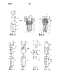
фиг.1 и 2 иллюстрируют первый вариант осуществления способа согласно изобретению, в котором запирающий элемент, подлежащий закреплению в отверстии в твердой ткани, представляет собой термопластичную вставку;1 and 2 illustrate a first embodiment of the method according to the invention, in which the locking element to be fixed in the hole in the solid fabric is a thermoplastic insert;
фиг.3 и 4 изображают другие варианты осуществления фиксаторов шовного материала и запирающих элементов, применимых в способе, который проиллюстрирован на фиг.1 и 2;figure 3 and 4 depict other embodiments of the suture clips and locking elements, applicable in the method, which is illustrated in figures 1 and 2;
фиг.5 и 6 иллюстрируют варианты осуществления фиксаторов шовного материала и запирающих элементов, которые могут использоваться в других вариантах осуществления способа согласно изобретению, причем запирающий элемент представляет собой термопластичный стержнь или интегрирован в фиксатор шовного материала;5 and 6 illustrate embodiments of suture fixators and locking elements that can be used in other embodiments of the method according to the invention, wherein the locking element is a thermoplastic rod or integrated into the suture anchor;
фиг.7 и 8A/В/С изображают другие варианты осуществления фиксаторов шовного материала и запирающих элементов;7 and 8A / B / C depict other embodiments of suture clips and locking elements;
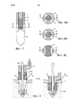
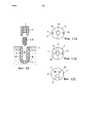
фиг.9 иллюстрирует еще один вариант осуществления способа согласно изобретению, в котором запирающий элемент представляет собой термопластичную втулку;Fig.9 illustrates another embodiment of a method according to the invention, in which the locking element is a thermoplastic sleeve;
фиг.10 и 11A/В/С иллюстрируют еще один вариант осуществления способа согласно изобретению, в котором запирающий элемент, закрепляемый в отверстии в твердой ткани, представляет собой термопластичный стержень, вставляемый во внутреннюю полость в фиксаторе шовного материала;10 and 11A / B / C illustrate yet another embodiment of the method according to the invention, in which the locking element fixed in the hole in the hard tissue is a thermoplastic rod inserted into the internal cavity in the suture anchor;
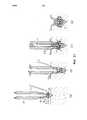
фиг.12 иллюстрирует еще один вариант осуществления способа согласно изобретению, содержащий промежуточный этап наматывания шовного материала вокруг фиксатора шовного материала;12 illustrates another embodiment of a method according to the invention, comprising an intermediate step of winding suture material around the suture anchor;
фиг.13 изображает предпочтительный вариант осуществления фиксатора шовного материала, применимый в способе, проиллюстрированному на фиг.12;FIG. 13 depicts a preferred embodiment of a suture anchor applicable in the method illustrated in FIG. 12;
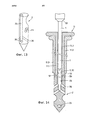
фиг.14 изображает устройство для фиксации фиксатора шовного материала в отверстии в твердой ткани согласно способу, проиллюстрированному на фиг.12.Fig.14 depicts a device for fixing the retainer of suture material in the hole in the hard tissue according to the method illustrated in Fig.12.
Во всех вариантах осуществления устройства и способа согласно изобретению шовный материал удерживается фиксатором, положение которого фиксируют в твердой ткани, причем средства для его удержания, показанные на чертежах, могут в каждом случае быть заменены известным средством для удержания шовного материала, будь то средство с возможностью перемещения шовного материала относительно фиксатора или средство для блокировки шовного материала относительно фиксатора шовного материала.In all embodiments of the device and method according to the invention, the suture material is held in place by a latch which is fixed in hard tissue, the means for holding it shown in the drawings can in each case be replaced by a known means for holding the suture material, whether it is a means for moving suture material relative to the retainer or means for locking the suture material relative to the suture anchor.
Предпочтительные варианты осуществленияPreferred Embodiments
На фиг.1 представлен первый вариант осуществления способа согласно изобретению, в котором простой фиксатор 2 шовного материала для прессовой посадки, аналогичный описанному, например, в публикациях US-5733307 (Dinsdale) или US-6508830 (Steiner), запирают в отверстии в твердой ткани с помощью запирающего элемента 3 в виде простой термопластичной вставки 31, содержащей материал с термопластичными свойствами или состоящей из него. Фиксатор 2 шовного материала, изготовленный, например, из материала кости или соответствующего заменителя, содержит для удержания шовного материала 4 канавку 21 шовного материала, которая проходит по дистальной поверхности фиксатора и, возможно, в осевом направлении вдоль периферийной поверхности фиксатора на противоположных сторонах фиксатора. При этом на этапе фиксации обеспечивают прессовую посадку фиксатора в отверстие 5 в твердой ткани так, что шовный материал 4 проходит по канавке 21 и, например, сохраняет возможность перемещаться относительно фиксатора шовного материала после обеспечения прессовой посадки (этап фиксации). Фиксатор 2 шовного материала и запирающий элемент 3 (термопластичная вставка 31), а также дистальный конец подходящего закрепляющего инструмента 1, показаны на левой стороне фиг.1.Figure 1 shows a first embodiment of the method according to the invention, in which a
Как показано на правой стороне фиг.1, фиксатор 2 шовного материала, например, установлен с прессовой посадкой в отверстие 5 в кости, которое проходит через кортикальный слой 7 в губчатую ткань 8 кости, расположенную под кортикальным слоем. При этом фиксатор шовного материала подлежит установке под кортикальным слоем, предпочтительно на глубине, превышающей длину фиксатора в осевом направлении, так что по меньшей мере часть термопластичной вставки 31 может достичь губчатой ткани 8 кости. Термопластичную вставку 31 затем закрепляют в стенке отверстия, предпочтительно по меньшей мере частично в губчатой ткани 8 кости, посредством вталкивания ее в отверстие при одновременном приложении энергии вибрации (или любой другого подходящего вида энергии), чтобы вызвать разжижение in situ материала с термопластичными свойствами и проникновение разжиженного материала в костную ткань стенки отверстия (в трабекулярную структуру стенки или, предпочтительно, в полости, вырезанные в стенке), где после вторичного затвердевания он образует соединение с положительной посадкой между термопластичной вставкой 31 и костной тканью. Вместе с тем предотвращается выход фиксатора 2 шовного материала из отверстия в твердой ткани, например, при ослаблении его соединения с прессовой посадкой с костной тканью, который таким образом заперт в отверстии 5 в твердой ткани. Принципы такого способа закрепления описаны, например, в публикации US-7335205. Результирующее закрепление является субкортикальным закреплением и не только запирает установленный с прессовой посадкой фиксатор 2 в отверстии 5, но может также блокировать шовный материал 4 относительно фиксатора 2 шовного материала. Если проксимальная поверхность фиксатора 2 шовного материала содержит подходящую структуру и/или материал, на этапе запирания может быть получено также соединение с положительной посадкой или сварной шов между дистальной поверхностью термопластичной вставки 31 и проксимальной поверхностью фиксатора.As shown on the right side of FIG. 1, the
Запирающий элемент 3, как показано на фиг.1, представляет собой термопластичную вставку 31, имеющую по существу такое же поперечное сечение, что и фиксатор шовного материала 3, возможно, немного большее. Это, однако, не является необходимым условием в иллюстрируемом варианте осуществления способа согласно изобретению, в котором термопластичная вставка 31 может иметь различную форму и, в частности, различные поперечные сечения. Термопластичная вставка 31 может иметь, например, полукруглое или звездообразное поперечное сечение и закрепляться только в части поверхности стенки отверстия в кости. Кроме того, она может иметь значительно большее поперечное сечение, чем фиксатор 2 шовного материала, и ее могут вставлять в увеличенный вход отверстия 5 в твердой ткани.The locking
В соответствии с фиг.1, для установки с прессовой посадкой фиксатора шовного материала в отверстие в твердой ткани можно использовать толкательный инструмент (не показан), причем толкательный инструмент имеет поперечное сечение, приспособленное к поперечному сечению фиксатора шовного материала или меньшее этого последнего, причем толкательный инструмент может быть оснащен для присоединения фиксатора шовного материала к дистальному концу толкателя. Для закрепления запирающего элемента толкательный инструмент необходимо извлечь из отверстия в твердой ткани. Для закрепления запирающего элемента используется соответствующим образом приводимый в действие закрепляющий инструмент 1, который, как вариант, может также использоваться как толкательный инструмент, причем закрепляющий инструмент может быть оснащен для присоединения запирающего элемента к дистальному концу инструмента.In accordance with FIG. 1, a push tool (not shown) can be used to press-fit the suture anchor into the hole in the hard tissue, the push tool has a cross section adapted to or less than that of the suture anchor, and the push the tool can be equipped to attach the suture anchor to the distal end of the follower. To secure the locking element, the push tool must be removed from the hole in the hard cloth. To secure the locking element, a suitably
Если закрепляющий инструмент 1 представляет собой виброинструмент, то есть при работе соединен с источником вибрации, и если он также используется для вталкивания фиксатора 2 в отверстие в твердой ткани или в твердую ткань на этапе фиксации, то усилие вталкивания может быть увеличено за счет вибрации инструмента также и на этапе фиксации. При этом может быть предпочтительным использование разных режимов вибрации для этих двух этапов способа. На этапе закрепления предпочтительно работать с по существу постоянной выходной мощностью вибрации, с вибрацией (базовой вибрацией) по существу постоянной частоты и амплитуды, причем частота находится в вышеупомянутом диапазоне частот и является резонансной частотой вибрационной системы, а амплитуда находится в диапазоне от 10 до 50 мкм, предпочтительно 20-40 мкм. Для этапа фиксации, предусматривающего вталкивание фиксатора в отверстие в твердой ткани или в твердую ткань, в частности, в случаях, когда твердая ткань оказывает высокое сопротивление, предпочтительны такие режимы вибрации, которые известны для распиливания костей с помощью вибрации. Такие режимы вибрации обычно содержат импульсы более высокой амплитуды и, возможно, с более острыми профилями (например, прямоугольный профиль или импульс Дирака), чем при базовой вибрации, и создаются, например, посредством модуляции амплитуды базовой вибрации, чтобы, например, сформировать импульсы более высокой амплитуды и предпочтительно также заострить входную волну, и посредством согласования с резонансной частотой системы. Созданные таким образом импульсы могут содержать один или несколько волновых циклов базовой вибрации каждый и могут быть периодическими с частотой модуляции предпочтительно в диапазоне 0,5-5 кГц или же могут генерироваться стохастически (по амплитуде и частоте модуляции), но в любом случае с совпадением по фазе с резонансной частотой системы. Средство производства стохастических импульсов описано, например, в публикации US 7172420 (St. Imier). В этом документе, высокая амплитуда импульсов предпочтительно превышает амплитуду базовой вибрации в 2-10 раз. В качестве альтернативы такие импульсы могут быть получены наложением на базовую вибрацию импульсного возбуждения от механического генератора импульсов (например, содержащим несбалансированную массу, приводимую во вращательное движение, или молот) или ее заменой этим импульсным возбуждением. При этом высокая амплитуда импульсов также предпочтительно превышает амплитуду базовой вибрации в 2-10 раз, и частота импульсов может быть регулярной в диапазоне от 20 до 200 Гц и, в частности, ниже самой низкой резонансной частоты вибрационной системы (например, нежелательного изгибного колебания сонотрода). Низкие частоты импульсов особенно важно, если фиксатор шовного материала состоит из материала, разжижаемого механической вибрацией, однако разжижение этого материала на этапе фиксации нежелательно.If the
На фиг.2 представлен способ, альтернативный способу с фиг.1, в котором при закреплении термопластичной вставки 31 в отверстии в твердой ткани ее проксимальная поверхность устанавливают приблизительно вровень с поверхностью 6 твердой ткани. В таком случае, и в особенности, если шовный материал 4 должен сохранять возможность перемещения относительно фиксатора 2 шовного материала, предпочтительно обеспечить в фиксаторе наличие осевого канала 22 для шовного материала, например, соединенного с дистальным ушком 23 или канавкой для удержания шовного материала 4, а также обеспечить наличие осевого канала 41, проходящего сквозь термопластичную вставку 31. Шовный материал, продетый через осевые каналы 22 и 41, не только остается вне зоны воздействия разжиженного материала и энергии (например, вибрации), используемой на этапе запирания, но также защищен от возможных повреждений о кромку твердой ткани на входе в отверстие при натяжении. Как показано на фиг.2, фиксатор 2 шовного материала может содержать проксимальный трубчатый выступ 42, который заходит внутрь осевого канала термопластичной вставки 31 для упрочнения осевого канала 41 вставки и, возможно, ее проксимального входа.Figure 2 presents a method alternative to the method of figure 1, in which when fixing the
Как показано на фиг.3 и 4, термопластичная вставка 31 может также содержать осевые канавки 40 и/или, как уже было указано при рассмотрении фиг.2, по меньшей мере один осевой канал 41 для приема шовного материала 4, причем такие канавки или канал могут иметь продолжение в закрепляющий инструмент 1. Осевой канал 41 в термопластичной вставке 31 может также служить для приема толкательного инструмента (не показан) для сохранения фиксатора 2 шовного материала неподвижным или удержания его в отверстии в твердой ткани на этапе запирания (см. также фиг.9) вместо или в дополнение к приему шовного материала.As shown in FIGS. 3 and 4, the
Если термопластичная вставка имеет осевой канал 41, как показано на фиг.4, для этапа фиксации и для этапа закрепления можно использовать комбинацию толкательного инструмента (не показан) и соответствующим образом приводимого в действие закрепляющего инструмента 1, при этом толкательный инструмент проходит сквозь осевой канал закрепляющего инструмента и имеет возможность смещения в осевом направлении относительного последнего. На этапе фиксации используется толкательный инструмент, а закрепляющий инструмент не активен, но может быть, вместе с запирающим элементом, уже установлен вокруг толкательного инструмента. На этапе запирания закрепляющий инструмент приводят в действие и прижимают к запирающему элементу, в то время как толкательный инструмент по-прежнему остается на месте или уже удален. Аналогичное использование толкательного инструмента и закрепляющего инструмента описано подробно ниже применительно к фиг.9.If the thermoplastic insert has an
Как показано на фиг.5, запирающий элемент 3 может иметь форму по меньшей мере одного термопластичного стержня 32 для вталкивания между фиксатором 2 шовного материала и стенкой отверстия в кости, причем фиксатор 2 шовного материала может содержать проходящие в осевом направлении канавки, предназначенные специально для направления термопластичных стержней 32 или служащие также канавками 21 для шовного материала, как проиллюстрировано. При этом такие канавки предпочтительно содержат материал и/или поверхностную структуру, способную образовывать сцепление соединяемых материалов или соединение с положительной посадкой с материалом термопластичного стержня после его разжижения и повторного затвердевания. В случае вталкивания термопластичных стержней 32 в канавки 21 для шовного материала, их закрепление в стенках отверстия в твердой ткани не только запирает фиксацию фиксатора 2 шовного материала в отверстии, но и блокирует шовный материал 4 относительно фиксатора. Принцип, реализуемый на этапе запирания в том виде, как это показано на фиг.5, описан для других применений в публикации WO 2008/034276.As shown in FIG. 5, the locking
Таким же образом, который был описан при рассмотрении фиг.4, фиксатор, проиллюстрированный на фиг.5, может быть зафиксирован и заперт посредством комбинации инструментов, в которой толкательный инструмент (не показан) имеет поперечное сечение, например, приспособленное к поперечному сечению фиксатора шовного материала, и по меньшей мере один соответствующим образом приводимый в действие закрепляющий инструмент (не показан) имеет поперечное сечение, приспособленное к поперечному сечению термопластичных стержней 32 и выполнен, например, с возможностью перемещения в осевом направлении в канавках толкательного инструмента. Это означает, что толкательный инструмент используется на этапе фиксации, а закрепляющий инструмент - на этапе запирания, причем перед этапом запирания толкательный инструмент либо извлекают с места установки, либо оставляют там, возможно, для временного удержания фиксатора в требуемом положении. В качестве альтернативы, как показано на чертеже, закрепляющий инструмент 1 выполнен так, что он может быть использован также и как толкательный инструмент, то есть он содержит по меньшей мере один дистальный зубец 1.1 (предпочтительно, чтобы число зубцов соответствовало количеству канавок 21 в фиксаторе шовного материала и количеству термопластичных стержней 32), выступающий из дистальной поверхности 1.2 инструмента. При этом зубцы 1.1 имеют поперечное сечение, приспособленное к поперечному сечению термопластичных стержней 32 и канавок 21 фиксатора шовного материала. На этапе фиксации инструмент 1 не приведен в действие, и по меньшей мере один зубец помещен в канавку 21 фиксатора шовного материала так, что дистальная поверхность 1.2 инструмента упирается в проксимальную поверхность фиксатора 2 шовного материала. После этапа фиксации инструмент 1 отводят от фиксатора шовного материала, термопластичные стержни помещают на одной линии с канавками 21 (которые могут быть присоединены к дистальным концам зубцов), инструмент приводят в действие и перемещают для вдавливания термопластичных стержней в канавки. Если инструмент 1 представляет собой виброинструмент, его можно привести в действие и на этапе фиксации, чтобы дополнительно способствовать вталкиванию фиксатора шовного материала в отверстие в твердой ткани или в твердую ткань, причем, как уже указывалось при рассмотрении фиг.1, режим вибрации, используемый на этапе фиксации, может отличаться от режима вибрации, используемого на этапе запирания.In the same manner as described in FIG. 4, the latch illustrated in FIG. 5 can be locked and locked using a combination of tools in which the push tool (not shown) has a cross section, for example adapted to the cross section of the suture lock material, and at least one appropriately driven fixing tool (not shown) has a cross section adapted to the cross section of
На фиг.6 показан еще один вариант осуществления этапа запирания способа согласно изобретению, в котором фиксатор 2 шовного материала содержит материал с термопластичными свойствами по меньшей мере в частях его периферийной поверхности (запирающий элемент 3 встроен в фиксатор 2 шовного материала). При этом его разжижение и закрепление осуществляется приложением соответствующим образом приводимого в действие закрепляющего инструмента 1, в частности, вибрирующего инструмента, к соответствующей части проксимальной поверхности фиксатора и продвижением инструмента 1 в дистальном направлении, тем самым вытесняя разжиженный материал с термопластичными свойствами в стенку отверстия в твердой ткани. Принцип, реализуемый на таком этапе запирания, описан для различных применений в публикации WO 2011/091545.6 shows another embodiment of the locking step of the method according to the invention, in which the
Для фиксации и запирания фиксатора шовного материала согласно фиг.6 возможно (но не показано) снова использовать толкательный инструмент и по меньшей мере один закрепляющий инструмент, причем инструменты выполнены с возможностью перемещения в осевом направлении относительно друг друга, причем толкательный инструмент может быть извлечен или может не быть извлечен перед этапом запирания. В качестве альтернативы, как показано на чертежах, закрепляющий инструмент 1 может быть выполнен с возможностью использования также в качестве толкательного инструмента. Такой инструмент 1 опять же имеет, например, два зубца 1.1, выступающих из дистальной поверхности 1.2 инструмента, причем, чтобы втолкнуть их в материал фиксатора шовного материала и чтобы они смогли вытеснить разжиженный материал в стенки отверстия в твердой ткани на этапе закрепления, зубцы 1.1 предпочтительно имеют внешний конус на своих дистальных концах. Для этапа фиксации инструмент не приведен в действие, но если он представляет собой виброинструмент, то он может быть приведен в действие, возможно, в режиме вибрации, который отличается от режима вибрации, используемого на этапе запирания (как описано выше), при этом зубцы помещают в канавки 21 для шовного материала фиксатора 2 шовного материала (или другие подобные канавки) так, что дистальная поверхность 1.2 инструмента упирается в проксимальную поверхность фиксатора. После этапа запирания инструмент 1 по меньшей мере частично извлекают так, чтобы выдвинуть зубцы 1.1 наружу из канавок 21 для шовного материала. И на этапе запирания инструмент 1 приводят в действие и поворачивают (в иллюстрируемом случае, например, на 90°), чтобы зубцы 1.1 больше не находятся на одной линии с канавками 21. Затем инструмент придвигают к фиксатору, предпочтительно не достаточно далеко для того, чтобы дистальная поверхность 1.2 инструмента упиралась в проксимальную поверхность фиксатора.For fixing and locking the suture anchor according to FIG. 6, it is possible (but not shown) to use the pusher tool and at least one fastening tool, the tools being axially movable relative to each other, the pusher tool can be removed or Do not be removed before the locking step. Alternatively, as shown in the drawings, the
Как уже было описано выше, при постановке фиксатора 2 шовного материала и запирающего элемента 3, фиксатор шовного материала может быть зафиксирован или удержан в отверстии в твердой ткани любым известным способом. В частности, может быть использован винт, ослабление которого и смещение к поверхности твердой ткани предотвращается на этапе запирания.As already described above, when setting the
Фиг.7 и фиг. 8A-8C иллюстрируют варианты осуществления устройства для выполнения способа согласно изобретению, причем устройство содержит фиксатор 2 шовного материала, запирающий элемент 3 и закрепляющий инструмент 1. На фиг.7 устройство изображено в осевом разрезе (по плоскости А-А на фиг.8A/В/С), и на фиг.8A/В/С в других варинатах разрезов (по плоскости В-В на фиг.7). Фиксатор 2 шовного материала изображен очень схематично, то есть без шовного материала и без средства для удержания шовного материала, при этом в качестве такого средства применимо любой известное на сегодняшний день средство. Запирающий элемент 3, который имеет форму вставки или стержня, и закрепляющий инструмент 1, используемый для этапа запирания, направляют с помощью канюлированного направителя и/или толкательного инструмента 11, который может также использоваться для вдавливания фиксатора 2 шовного материала в отверстие в твердой ткани или в твердую ткань и, в зависимости от конструкции и способа, извлекается перед этапом закрепления или остается на месте, возможно, для временного удержания фиксатора шовного материала. Поперечное сечение этого толкательного инструмента 11 соответствует поперечному сечению фиксатора 2 шовного материала.7 and FIG. 8A-8C illustrate embodiments of a device for carrying out the method according to the invention, the device comprising a
Как показано на фиг.8A, толкательный инструмент 11 может содержать дистальную часть с прорезями, в которую может входить запирающий элемент 3, не соприкасаясь со стенкой отверстия в твердой ткани, в которой должен быть зафиксирован и заперт фиксатор, из-за чего он не может разжижаться от вибрирующих движений относительно указанных стенок, как это происходит в способах, описанных со ссылками на предыдущие чертежи. Чтобы достичь разжижения материала запирающего элемента 3, например, начиная с дистального конца, и чтобы привести разжиженный материал в контакт со стенкой отверстия в твердой ткани через прорези в дистальной части толкательного инструмента 11, проксимальная поверхность фиксатора 2 шовного материала или дистальная поверхность запирающего элемента 3 снабжены средствами направления энергии (например, проксимальная поверхность фиксатора заострена, как показано на фиг.7). После этапа фиксации толкательный инструмент 11 либо оставляют на месте для удержания фиксатора шовного материала, либо извлекают. После этапа запирания закрепляющий инструмент 1 и, возможно, толкательный инструмент 11 извлекают из места фиксации.As shown in FIG. 8A, the
В альтернативном варианте осуществления устройства (который изображен в разрезе на фиг.8В) участок с прорезями является не частью толкательного инструмента 11, а частью фиксатора 2 шовного материала и не извлекается после завершения процедуры закрепления. Вместо прорезей эта часть фиксатора 2 шовного материала может содержать фенестрации или другие подходящие виды перфорации.In an alternative embodiment of the device (which is shown in section in FIG. 8B), the slotted portion is not part of the
Разрез на фиг.8C иллюстрирует комбинацию способов, изображенных на фиг.1 и 7, в которой запирающий элемент 3 может разжижаться при контакте со стенкой отверстия в твердой ткани (способ фиг.1) и/или на его дистальном конце (способ фиг.7 с разрезами на фиг.8A/В) в зависимости от формы и размера отверстия в твердой ткани.The cross-section in FIG. 8C illustrates a combination of the methods depicted in FIGS. 1 and 7, in which the
На фиг.9 представлен еще один вариант осуществления способа согласно изобретению, который предусматривает запирание фиксатора 2 шовного материала, удерживаемого в отверстии в твердой ткани временно толкательным инструментом 11, причем фиксатор шовного материала 2 может быть прикреплен к толкательному инструменту 11, например, посредством надвижного соединения. Введение фиксатора 2 шовного материала в отверстие в твердой ткани или в твердую ткань и удержание его там с помощью толкательного инструмента 11 представляют собой этап фиксации в этом варианте осуществления способа согласно изобретению. Этап запирания осуществляется с помощью запирающего элемента 3 в форме термопластичной втулки 33 и канюлированного закрепляющего инструмента 1, через который проходит толкательный инструмент. Для удержания фиксатора шовного материала 2 в отверстии в кости могут, как необязательный вариант, использоваться дополнительные средства, например резьба, прессовая посадка, шипы и т.д., и сам фиксатор может удерживать шовный материал 4 с возможностью перемещения или без такой возможности. Этот вариант осуществления является усовершенствованием фиксатора для шовного материала, описанного в публикации US 2009/187216 (Arthrex), который удерживается в отверстии в кости с помощью толкательного инструмента и затем запирается с помощью канюлированного винта. Преимущества, достигаемые с помощью этого усовершенствования, связаны, в частности, с тем, что закрепление с помощью материала с термопластичными свойствами оказывается возможным и в непрочной костной ткани, где винт не может надежно удерживаться; что запирающий элемент 3 не обязательно должен иметь круглое поперечное сечение, как это необходимо для винта; что запирающий элемент 3 может иметь ту же механическую прочность, что и винт, при меньшем поперечном сечении, и запертые таким образом фиксаторы могут быть зафиксированы на меньших расстояниях друг от друга, и, наконец, что немаловажно, запирающий элемент 3 не подвергает шовный материал опасности перекручивания и повреждения, как это могло бы случиться при использовании винта.Figure 9 shows another embodiment of the method according to the invention, which provides for locking the
В левой части фиг.9 показано устройство для выполнения способа, которое содержит фиксатор 2 шовного материала, термопластичную втулку 33, толкательный инструмент 11 и соответствующий закрепляющий инструмент 1 для закрепления термопластичной втулки 33 в отверстии в твердой ткани в конфигурации, подготовленной для этапа запирания. Закрепляющий инструмент 1 содержит канюлированную дистальную часть (или полностью канюлирован), через которую проходит толкательный инструмент 11 (и, возможно, шовный материал 4), причем термопластичная втулка 33 располагается между фиксатором 2 шовного материала и дистальным концом закрепляющего инструмента 1. Фиксатор 2 шовного материала может быть первоначально помещен в отверстие в твердой ткани, подготовленном заранее, или же может быть пригоден для введения в твердую ткань без предварительного создания отверстия. В правой части фиг.9 изображена постановка элементов оборудования после этапа запирания, когда термопластичная втулка 33 с помощью приведенного в действие закрепляющего инструмента введена в отверстие в твердой ткани и при этом закреплена в стенке отверстия в твердой ткани. Для завершения запирающей фиксации фиксатора 2 шовного материала, толкательный инструмент 11 и закрепляющий инструмент 1 извлекают с места установки фиксатора.On the left side of FIG. 9, a device for performing the method is shown, which comprises a
Как уже было рассмотрено со ссылкой на фиг.1, глубина отверстия в твердой ткани и длина фиксатора шовного материала в осевом направлении предпочтительно подобраны относительно друг друга таким образом, что закрепление термопластичной втулки 33, достигаемое на этапе запирания, по меньшей мере частично, является субкортикальным закреплением.As already discussed with reference to figure 1, the depth of the hole in the solid fabric and the length of the suture retainer in the axial direction are preferably selected relative to each other so that the fixing thermoplastic sleeve 33, achieved at the stage of locking, at least partially, is subcortical fastening.
На фиг.10 и фиг. 11A/В/C представлены другие варианты осуществления способа согласно изобретению, которые имеют сходства с вариантом осуществления, рассмотренным со ссылкой на фиг.7 и 8В. Здесь на фиг.10 изображен осевой разрез фиксатора 2 шовного материала и запирающего элемента 3, который представляет собой термопластичный стержень 32. На фиг.11A/В/С показаны аналогичные фиксаторы со стороны их проксимальной поверхности. Фиксатор 2 шовного материала, подходящий для данного варианта осуществления способа согласно изобретению, содержит внутреннюю полость 25, открытую на проксимальной поверхности фиксатора и соединенную с периферийной поверхностью фиксатора посредством проходов 26. Шовный материал, который на фиг.10 и 11/В/С не показан, удерживается фиксатором любым подходящим способом. Фиксатор 2 шовного материала зафиксирован в отверстии 5 в твердой ткани, например, посредством прессовой посадки, винтовой резьбы, шипов или других подходящих удерживающих средств или же просто за счет удержания в отверстии соответствующим толкательным инструментом (не показан), и при этом запирающий элемент 3 (термопластичный стержень 33, имеющий форму, приспособленную к внутренней полости 25), вводят в указанную полость при одновременной передаче к его проксимальной поверхности энергии вибрации (или любого другого подходящего вида энергии), что приводит к разжижению материала с термопластичными свойствами по меньшей мере на поверхностных участках запирающего элемента 3, где последний контактирует с поверхностью внутренней полости 25. Разжиженный материал выталкивается через проходы 26 при введении термопластичного стержня 32 (запирающего элемента 3) глубже в полость 25 и проникает в костную ткань стенки отверстия 5, образуя здесь после повторного затвердевания соединение с положительной посадкой между фиксатором 2 шовного материала и стенкой отверстия 5. Принцип, реализуемый на этом этапе запирания, описан для различных применений в публикации US 7335205.10 and FIG. 11A / B / C presents other embodiments of the method according to the invention, which are similar to the embodiment discussed with reference to FIGS. 7 and 8B. Here, FIG. 10 shows an axial section through the
Запирающий элемент 3 согласно варианту осуществления, показанному на фиг.10, может не представлять собой, как показано, отдельный термопластичный стержень 32, а составлять единое целое с фиксатором 2 шовного материала, располагаясь в центре фиксатора, при этом этап запирания дополнительно предусматривает вталкивание соответствующего виброинструмента в материал фиксатора для разжижения этого материала и для вытеснения его через радиальные проходы к периферийной поверхности фиксатора. Принцип, реализуемый на таком этапе запирания, описан для различных применений в публикации WO 2008/128588 (Stryker Trauma GmbH).The locking
На фиг.11A/В/С показаны примеры фиксаторов 2 шовного материала, которые подходят для этапа запирания, описанного выше со ссылкой на фиг.10. При этом фиксаторы показаны со стороны их проксимальной поверхности. Эти фиксаторы отличаются друг от друга, в частности, тем образом, которым шовный материал 4 удерживается фиксатором 2 шовного материала, и конфигурацией внутренней полости 25 и проходов 26.11A / B / C show examples of
На фиг.11A фиксатор 2 шовного материала содержит пару противолежащих осевых канавок 21 для шовного материала, описанных подробнее выше со ссылками на фиг.1 и 3-6, причем эти канавки 21 соединены друг с другом не показанной на чертеже поперечной канавкой или ушком. Внешние входы проходов 26, соединяющие внутреннюю полость 25 фиксатора с периферийной поверхностью фиксатора, располагаются на удалении от канавок 21 для шовного материала. Описанный фиксатор шовного материала может использоваться с шовным материалом, который должен сохранить возможность перемещения относительно фиксатора 2 шовного материала даже после этапа запирания, и/или может использоваться с шовным материалом, чувствительным к нагреву, который должен быть защищен от вступления в контакт с разжиженным материалом, имеющим термопластичные свойства.In FIG. 11A, the
На фиг.11B фиксатор 2 шовного материала также содержит канавки 21 для шовного материала, внутреннюю полость 25 и проходы 26, причем по меньшей мере некоторые из внешних входов проходов 26 расположены внутри канавок 21 для шовного материала. Описанный фиксатор шовного материала подходит для этапа запирания, в котором шовный материал 4 должен быть заблокирован относительно фиксатора, посредством фиксации ее в канавке 21 для шовного материала с помощью материала, имеющего термопластичные свойства, повторно затвердевающего в канавке 21 для шовного материала и охватывающего помещенный в нее шовный материал 4.11B, the
На фиг.11C фиксатор 2 шовного материала содержит, вместо канавки для шовного материала с фиг.11A/В, по меньшей мере один осевой канал 22 для шовного материала (возможно, соединенный дистальной поперечной канавкой или каналом, которые не показаны), причем каналы для шовного материала проходят через фиксатор шовного материала приблизительно параллельно оси фиксатора, причем внутренняя полость 25 может быть расположена эксцентрично. Как и фиксатор с фиг.11A, фиксатор на фиг.11C подходит для применений, в которых шовный материал должен сохранять возможность перемещения относительно запертого фиксатора, и/или для использования с шовным материалом, чувствительным к нагреву.In FIG. 11C, the
Как уже указывалось со ссылкой на фиг.7 и 8A/В/С, способ, изображенный на фиг.10, может выполняться с помощью по меньшей мере дистально канюлированного направителя/толкательного инструмента 11 и закрепляющего инструмента 1, при этом закрепляющий инструмент 1 перемещают в канюлированном толкательном инструменте 11 в осевом направлении. В альтернативном варианте в качестве толкательного инструмента может использоваться закрепляющий инструмент 1, поперечное сечение которого приспособлено к внутренней полости 25 фиксатора 2 шовного материала, причем на этапе фиксации он воздействует на дно внутренней полости 25 фиксатора, при этом после этапа фиксации его извлекают, чтобы поместить в этой полости 25 запирающий элемент 3, и на этапе запирания этот инструмент 1 воздействует на проксимальную поверхность запирающего элемента 3. Если при этом закрепляющий инструмент 1 представляет собой виброинструмент, он может также приводиться в действие и на этапе фиксации, чтобы вибрация способствовала вталкиванию фиксатора шовного материала в отверстие в твердой ткани или в твердую ткань. Если же не приводить в действие закрепляющий инструмент для такого вталкивания или если использовать для такого вталкивания режим вибрации (с небольшой частотой вибрации, см. подробный комментарий выше), который не обеспечивает разжижение материала запирающего элемента, то можно использовать инструмент 1 даже для воздействия на проксимальную поверхность запирающего элемента 3 уже на этапе фиксации.As already mentioned with reference to FIGS. 7 and 8A / B / C, the method depicted in FIG. 10 can be performed using at least a distally cannulated guide /
На фиг.12, 13 и 14 представлен еще один вариант осуществления способа согласно изобретению и устройства для выполнения способа, причем способ и устройства имеют сходства со способом, проиллюстрированным на фиг.10 и 11A/В/С. В соответствии с настоящим способом, фиксатор 2 шовного материала содержит внутреннюю полость 25, описанную со ссылками на фиг.10 и 11A/В/С, и шовный материал 4 удерживается фиксатором, например, благодаря тому, что продет через дистальное ушко 23 или канавку. Фиксатор 2 шовного материала помещают и/или фиксируют в отверстии в твердой ткани или вталкивают в отверстие в твердой ткани с помощью канюлированного толкательного инструмента 11 и удерживают в твердой ткани с помощью этого инструмента (этап фиксации). На промежуточном этапе регулируют натяжение шовного материала или укорачивают шовный материал, поворачивая фиксатор шовного материала вокруг его оси с помощью толкательного инструмента 11 и одновременно удерживая шовный материал так, чтобы он наматывался вокруг фиксатора. При достижении удовлетворительного натяжения шовного материала фиксатор запирают (этап запирания) в твердой ткани с помощью термопластичного стержня 32 (запирающий элемент 3), как описано выше со ссылками на фиг.10 и 11A/В/С.12, 13 and 14 show yet another embodiment of the method according to the invention and the device for performing the method, the method and devices resembling the method illustrated in FIG. 10 and 11A / B / C. According to the present method, the
Промежуточный этап наматывания шовного материала вокруг фиксатора шовного материала, зафиксированного подходящим образом на толкательном инструменте, может также выполняться в способе, представленном на фиг.9.An intermediate step of winding suture material around a suture anchor appropriately fixed to the pusher tool may also be performed in the method of FIG. 9.
На фиг.12 показаны четыре последовательных фазы (a)-(d) описанного выше способа. Фиксатор 2 шовного материала содержит систему каналов и/или канавок для удержания шовного материала 4, например, как показано на чертеже, простое ушко 23, через которое продевают шовный материал 4, а также внутреннюю полость 25, открытую на проксимальной поверхности фиксатора шовного материала и соединенную с периферийной поверхностью фиксатора 2 шовного материала посредством проходов 26. Дистальный конец фиксатора 2 шовного материала может иметь форму, позволяющую втолкнуть его в костную ткань, например наподобие костного шила, которое можно протолкнуть не только сквозь губчатый, но и сквозь кортикальный слой кости. В этом случае дистальный конец фиксатора должен быть изготовлен из достаточно прочного материала, например, из PEEK, причем проксимальная часть фиксатора содержит внутреннюю полость 25, проходы 26 и, возможно, ушко 23, изготовленные, например, из биокомпозитного материала (примеры таких материалов перечислены выше). Фиксатор 2 шовного материала присоединен к дистальному концу канюлированного толкательного инструмента 11, который в данном применении служит не только для вдавливания фиксатора шовного материала в твердую ткань и направления закрепляющего инструмента 1, но также служит и для поворачивания фиксатора шовного материала в твердой ткани (толкательный/вращательный инструмент). Осевой канал толкательного инструмента 11 имеет поперечное сечение, приспособленное к поперечному сечению внутренней полости 25 фиксатора 2 и закрепляющего инструмента 1. Соединение между дистальным концом толкательного инструмента 11 и фиксатором 2 выполнено для передачи толкающего усилия и момента кручения фиксатору 2 шовного материала.12 shows four successive phases (a) to (d) of the above method. The
На фазе (а) фиксатор 2, прикрепленный к толкательному инструменту 11, вдавливают в отверстие в твердой ткани или вбивают в твердую ткань, причем шовный материал 4 может сохранять возможность перемещения через ушко 23. На фазе (b) натяжение шовного материала регулируют поворотом фиксатора 2 за счет поворачивания толкательного инструмента 11, причем шовный материал 4 удерживается таким подходящим образом, что наматывается вокруг фиксатора 2, который может содержать шейку, т.е. участок с уменьшенным поперечным сечением, для размещения на нем намотанного шовного материала. Положение фиксатора при вращении стабилизируется за счет трения между твердой тканью и фиксатором 2 шовного материала или, возможно, шовным материалом 4 и/или за счет внешнего удерживания толкательного инструмента 11. Наматываемый шовный материал при этом натягивается, и блокируется относительно фиксатора и твердой ткани, по меньшей мере временно. На фазе (с) запирающий элемент 3 (термопластичный стержень 32) вместе с дистальным концом закрепляющего инструмента 1 (в частности, виброинструмента) вводят через толкательный инструмент 11 во внутреннюю полость 25 фиксатора 2. Для этапа запирания закрепляющий инструмент 1 приводят в действие (вызывают его вибрацию) и продвигают в сторону фиксатора шовного материала, чтобы вызвать разжижение материала термопластичного стержня 32 и выдавить разжиженный материал через проходы 26. Во время процесса разжижения термопластичный стержень 32 и закрепляющий инструмент 1 направляются по осевому каналу толкательного инструмента 11, при этом разжиженный материал выталкивается через проходы 26, проникая в твердую ткань, окружающую фиксатор 2. Для фазы (d) показан фиксатор 2 шовного материала после фиксации в твердой ткани и после извлечения толкательного инструмента 11 и закрепляющего инструмента 1.In phase (a), the
К другим возможным способам запирания фиксатора на фиг.12 относится способ, описанный в публикации WO 2009/132472, или же способ с использованием распределителя, описанного в публикации WO 2010/127462, содержание которых полностью включено в настоящий документ посредством ссылки. Кроме того, вместо внутренней полости 25 и проходов 26, фиксатор 2 может содержать по меньшей мере одну канавку, проходящую в осевом направлении вдоль его периферийной поверхности, причем запирающий элемент выполнен с возможностью продвижения в этой канавке (см. фиг.5), как описано в публикации WO 2008/034276, содержание которой полностью включено в настоящий документ посредством ссылки.Other possible methods of locking the latch in FIG. 12 include the method described in WO 2009/132472, or the method using the dispenser described in WO 2010/127462, the contents of which are incorporated herein by reference in their entirety. In addition, instead of the
Чтобы передавать усилие, необходимое для введения фиксатора шовного материала в твердую ткань и для поворачивания фиксатора в твердой ткани, соединение между фиксатором 2 шовного материала и толкательным инструментом 11 должно иметь способность передавать толкающие и вращающие усилия, а также должно быть легко отсоединяемым, обеспечивая извлечение инструмента после процесса фиксации. Такое соединение обеспечивается, например, посредством надвижного соединения, содержащего входящие в зацепление ступенчатые структуры на дистальной поверхности толкательного инструмента 11 и на проксимальной поверхности фиксатора 2 шовного материала, либо посредством сопряжения некруглой (например, многоугольной) дистальной части осевого канала толкательного инструмента 11 с имеющей соответствующую форму проксимальной частью фиксатора 2 шовного материала, либо посредством сопряжения некруглой (например, многоугольной) дистальной части толкательного инструмента 11 с соответствующим углублением в фиксаторе 2 шовного материала. Предпочтительно, это соединение обеспечивает не слишком плотную посадку с натягом так, чтобы можно было манипулировать сборным узлом, состоящим из фиксатора 2 шовного материала и толкательного инструмента 11, до процедуры фиксации без излишних мер предосторожности.In order to transmit the force required to insert the suture anchor into the hard tissue and to rotate the anchor in the hard tissue, the connection between the
Как уже было рассмотрено со ссылками на фиг.10 и 11A/В/С, расположение внутренней полости 25 фиксатора 2 шовного материала и проходов 26 по отношению к системе каналов и/или канавок для удержания шовного материала зависит от цели, для которой шовный материал 4 прикрепляется к твердой ткани, и от характеристик шовного материала, в частности, от его устойчивости к нагреву и, возможно, вибрации (энергии, передаваемой через закрепляющий инструмент). Фиксатор 2 шовного материала, как показано на фиг.12, содержит проходы 26, внешние входы которых располагаются в той области фиксатора, вокруг которой наматывают шовный материал 4 на промежуточном этапе. Это означает, что шовный материал 4 войдет в контакт с разжиженным материалом и будет окружен им, причем после повторного затвердения разжиженный материал запрет не только фиксатор 2 относительно твердой ткани, но и шовный материал 4 относительно фиксатора 2, но также может ухудшить механическую целостность шовного материала, что неприемлемо для чувствительного шовного материала.As already discussed with reference to FIGS. 10 and 11A / B / C, the location of the
Чтобы избежать такого отрицательного воздействия, требуется соответствующая конструкция фиксатора шовного материала (в частности, соответствующее относительное расположение проходов 26 и средств для удержания шовного материала 4), например, такая, в которой входы в проходы 26 имеют более дистальное расположение, чем область фиксатора, на которой шовный материал расположен снаружи фиксатора шовного материала, и, в частности, где он намотан вокруг фиксатора шовного материала.In order to avoid such negative impact, an appropriate design of the suture retainer is required (in particular, the corresponding relative arrangement of the
Один из примеров такого расположения представлен на фиг.13. В фиксаторе шовного материала, как показано на фиг 3, внутренняя полость 25 и ушко 23 (или другое подходящее средство для удержания шовного материала) расположены эксцентрично, причем внутренняя полость 25 с дистальной стороны проходит за ушко 23, и входы в проходы 26 располагаются на дистальном конце периферийной поверхности фиксатора и/или на дистальной поверхности фиксатора. Если использовать такой фиксатор шовного материала при осуществлении способа, изображенного на фиг.12, шовный материал не будет вступать в контакт с разжиженным материалом, который в этом случае служит исключительно для запирания фиксатора 2 в твердой ткани на нужной глубине и с нужным поворотом.One example of such an arrangement is shown in FIG. In the suture anchor, as shown in FIG. 3, the
На фиг.14 очень схематично показан вариант осуществления устройства для выполнения способа, описанного со ссылкой на фиг.12. Устройство содержит, как уже описано со ссылкой на фиг.12, закрепляющий инструмент 1 и канюлированный толкательный инструмент 11, который служит также для направления закрепляющего инструмента 1 и для поворачивания и, возможно, удерживания фиксатора 2 шовного материала. Толкательный инструмент 11 содержит канюлированную внутреннюю часть 11.1 и канюлированную внешнюю часть 11.2, причем закрепляющий инструмент 1 выполнен с возможностью вставки в осевой канал во внутренней части 11.1 инструмента, и внутренняя часть 11.1 инструмента выполнена с возможностью вставки в осевой канал внешней части 11.2 инструмента.On Fig very schematically shows an embodiment of a device for performing the method described with reference to Fig. The device comprises, as already described with reference to FIG. 12, a
Дистальная поверхность закрепляющего инструмента 1 приспособлена для вдавливания термопластичного стержня 32 (запирающего элемента 3) во внутреннюю полость 25 фиксатора 2 и для передачи энергии, необходимой для процесса разжижения термопластичного стержня и, предпочтительно, для удержания термопластичного стержня (например, имеет выступ на дистальной поверхности инструмента, устанавливаемый с прессовой посадкой в соответствующем углублении на проксимальной поверхности стержня).The distal surface of the
Дистальный конец внутренней части 11.1 инструмента оснащен для удержания фиксатора 2 и для передачи толкательного усилия фиксатору, например, внешней резьбой 50, взаимодействующей с внутренней резьбой, расположенной на входе во внутреннюю полость 25 фиксатора 2 шовного материала. Проксимальный конец внутренней части 11.1 инструмента предпочтительно имеет выпуклость или фланец, который служит рукояткой.The distal end of the inner part 11.1 of the tool is equipped to hold the
Дистальный конец внешней части 11.2 инструмента оснащен для передачи момента кручения на фиксатор 2, например, ступенчатой дистальной поверхностью, взаимодействующей с соответствующим ступенчатым краем проксимальной поверхности фиксатора 2 (например, двумя или четырьмя стержневыми зубцами, выступающими из дистального конца этой части инструмента и выполненными с возможностью входа в зацепление с двумя или четырьмя впадинами, проходящими от проксимальной поверхности фиксатора внутрь периферийной поверхности фиксатора). Тот же эффект может быть достигнут, например, посредством выполнения дистального конца осевого канала внешней части 11.2 инструмента с многоугольным (например, шестиугольным) поперечным сечением и посредством снабжения соответствующим многоугольным поперечным сечением наиболее проксимальной части фиксатора 2 шовного материала. Проксимальный конец внешней части 11.2 инструмента предпочтительно имеет выпуклость или фланец, который служит рукояткой, или же может быть выполнен в виде динамометрического ключа, для ограничения натяжения шовного материала.The distal end of the outer part 11.2 of the tool is equipped to transmit the torsion moment to the
Фиксатор 2 шовного материала, показанный на фиг.14 функционально схож с фиксаторами, показанными на фиг. 12-13, и содержит внутреннюю полость 25 и проходы 26 и, например, ушко 23 для удержания шовного материала (не показано). Внешние входы в проходы 26 имеют более проксимальное расположение, чем ушко и область фиксатора шовного материала, вокруг которой наматывают шовный материал. Это означает, что разжиженный материал может вступить в контакт с шовным материалом, проходящим в проксимальном направлении от области фиксатора, вокруг которой он намотан, что можно предотвратить посредством размещения входов в проходы на противоположных сторонах фиксатора двумя рядами в осевом направлении и посредством выполнения между этими рядами осевых канавок для шовного материала.The
Для подготовки устройства, показанного на фиг.14, к фиксации способом согласно изобретению (с этапом фиксации и этапом запирания) внутреннюю часть 11.1 инструмента располагают во внешней части 11.2 инструмента и фиксатор 2 шовного материала фиксируют на дистальных концах этих частей, привинчивая внутреннюю часть 11.1 инструмента к фиксатору 2 шовного материала, причем дистальные длины указанных двух частей инструмента приспособлены друг к другу таким образом, что в то же время входящие в зацепление части фиксатора 2 шовного материала и внешняя часть 11.2 инструмента вдавливаются друг в друга. Термопластичный стержень 32, прикрепленный к дистальному концу инструмента 1, может быть затем введен во внутреннюю часть 15.1 инструмента. В качестве альтернативного варианта, закрепляющий инструмент 1 отдельно или закрепляющий инструмент 1 вместе с термопластичным стержнем 32 может быть введен во внутреннюю часть инструмента только после этапа фиксации. Шовный материал продевают через ушко 23.To prepare the device shown in FIG. 14 for fixing by the method according to the invention (with the fixing step and the locking step), the inner part 11.1 of the instrument is located in the outer part 11.2 of the instrument and the
После этого фиксатор 2 шовного материала вводят в отверстие в твердой ткани или в твердую ткань, прикладывая толкающее усилие к внутренней части 11.1 инструмента. Когда фиксатор 2 шовного материала достиг необходимой глубины в твердой ткани, что может контролироваться заплечиком 52 на внешней части 11.2 инструмента, опирающегося на поверхность твердой ткани, внешнюю часть 11.2 инструмента поворачивают вокруг оси, поворачивая вместе с ней фиксатор 2 шовного материала и, возможно, внутреннюю часть 11.1 инструмента и одновременно наматывая шовный материал вокруг фиксатора 2 шовного материала, при этом натяжение шовного материала или его сопротивление наматыванию может контролироваться известным на сегодняшний день способом, например, посредством выполнения внешней части 11.2 инструмента в виде динамометрического ключа. Когда, посредством наматывания шовного материала, шовный материал будет достаточно натянут или укорочен, внешнюю часть 11.1 инструмента удерживают неподвижно и закрепляющий инструмент 1 приводят в действие (предпочтительно сообщая ему вибрацию) и толкают по направлению к фиксатору 2 шовного материала. Рабочий ход закрепляющего инструмента 1 можно контролировать с помощью заплечика 53 на закрепляющем инструменте 1, причем заплечик опирается на проксимальную поверхность внутренней части 11.1 инструмента, когда термопластичный стержень имеет требуемую укороченную длину или когда достаточное количество материала термопластичного стержня 32 выдавлено через проходы 26.After that, the
После повторного затвердевания материала термопластичного стержня 32, закрепляющий инструмент 1 отделяют от термопластичного стержня 32 и извлекают, а обе части 11.1 и 11.2 инструмента отделяют от фиксатора 2 шовного материала, отвинчивая внутреннюю часть 11.1 инструмента и вытягивая внешнюю часть 11.2 инструмента из фиксатора 2 шовного материала, и части инструмента также извлекают. Шовный материал проходит от поверхности кости между костной тканью и фиксатором 2 шовного материала. Как было упомянуто ранее для других вариантов осуществления изобретения, и в способе, представленном на фиг.12, и в устройстве, изображенном на фиг.14, фиксатор 2 шовного материала может быть зафиксирован на различных глубинах в твердой ткани. На фиг.12 изображено субкортикальное закрепление. Фиксатор шовного материала, представленный на фиг.13, подходит для фиксации с проксимальной поверхностью примерно на одном уровне с поверхностью твердой ткани. На фиг.14 изображен еще один фиксатор шовного материала, подходящий для субкортикального закрепления.After the solidification of the material of the
Для облегчения вталкивания фиксатора в твердую ткань, дистальная поверхность фиксатора может соответствующим образом сужаться или заостряться, но также может быть выполнена в виде перфоратора для пробивания отверстий с помощью вибрации, как описано в публикации WO 2008/131884 (Stryker Trauma GmbH). Для такого вталкивания с помощью вибрации либо толкательный инструмент подвергается соответствующей вибрации, либо закрепляющий инструмент снабжен дистальным придатком, достигающим дна внутренней полости 25 и способным передавать вибрацию фиксатору шовного материала, причем этот придаток должен быть извлечен и вставлен термопластичный стержень между этапом фиксации и этапом запирания. Приведенные выше соображения на эту тему со ссылкой на фиг.10 применимы и для варианта осуществления, показанном на фиг. 12-14. Фиксаторы менее эффективной конструкции можно втолкнуть только в губчатый слой кости, при этом кость, в которой фиксируется фиксатор, зачищают от кортикального слоя или выполняют отверстие, проходящее только через кортикальный слой кости. Кроме того, фиксатор шовного материала можно втолкнуть в малое направляющее отверстие, глубина и/или поперечное сечение которого будут увеличены посредством вталкивания в него фиксатора шовного материала.To facilitate the pushing of the latch into the hard tissue, the distal surface of the latch can taper or sharpen accordingly, but can also be made as a hammer drill for punching holes by vibration, as described in WO 2008/131884 (Stryker Trauma GmbH). For such pushing by vibration, either the pusher tool is subjected to the corresponding vibration, or the fixing tool is equipped with a distal appendage reaching the bottom of the
Описанное выше изобретение относится, в частности, к фиксаторам шовного материала, используемым для прикрепления мягкой ткани к твердой ткани. Во всех описанных вариантах осуществления способов фиксации таких фиксаторов шовного материала в твердой ткани, шовный материал может быть защищен от повреждений, связанных с рассеянием тепла от материала, имеющего термопластичные свойства, при его разжижении, за счет пропитки его жидкостью (водой или физиологическим раствором), предпочтительно до продевания через фиксатор шовного материала или до помещения в отверстие в твердой ткани вместе с фиксатором шовного материала, и обязательно до разжижения материала с термопластичными свойствами.The invention described above relates in particular to suture anchors used to attach soft tissue to hard tissue. In all the described embodiments of the methods of fixing such suture material fixers in hard tissue, the suture material can be protected from damage associated with heat dissipation from a material having thermoplastic properties when it is diluted by impregnating it with a liquid (water or physiological saline), preferably prior to threading the suture through the fixative or before being inserted into the hole in the hard tissue together with the suture fixative, and be sure to thin the material with thermoplastic sstv.
Во всех описанных выше способах присоединения мягкой ткани к твердой ткани с помощью фиксатора шовного материала и шовного материала, материал, имеющий термопластичные свойства и содержащийся в запирающем элементе, разжижается, предпочтительно, чтобы проникнуть в твердую ткань или полости, предусмотренные в твердой ткани, и после повторного затвердевания образовать соединение с положительным натягом между запирающим элементом и, возможно, фиксатором шовного материала, с одной стороны, и твердой тканью стенки отверстия, с другой стороны. В тех случаях, когда отверстие в твердой ткани выполняется перед этапом фиксации, такие соединения с положительным натягом могут быть получены в результате двухэтапной процедуры. При этом стенки отверстия в твердой ткани подвергаются предварительной обработке способом, описанным в публикациях WO 2010/045751 или WO 2009/141252 (Nexilis), когда материал с термопластичными свойствами в разжиженном состоянии выдавливается в твердую ткань стенки отверстия, образуя вместе с этой тканью своего рода композит, но по существу без покрытия этой стенки материалом, имеющим термопластичные свойства. Вслед за этим, на втором этапе выполняется процесс закрепления, описанный в настоящем документе и в цитируемых публикациях, при этом разжиженный материал не может проникнуть в композитный материал стенки отверстия в твердой ткани, полученного на этапе предварительной обработки, а приваривается к композитному материалу этой стенки. Условием такого приваривания является способность материала с термопластичными свойствами, используемого на этапе закрепления, свариваться с материалом с термопластичными свойствами, используемым на этапе предварительной обработки. Предпочтительно, чтобы оба материала с термопластичными свойствами содержали одинаковый термопластичный полимер.In all the methods described above for attaching soft tissue to hard tissue using a suture anchor and suture material, a material having thermoplastic properties contained in the locking member is liquefied, preferably to penetrate into the hard tissue or cavities provided in the hard tissue, and after re-harden to form a connection with a positive interference between the locking element and, possibly, the suture anchor, on the one hand, and the solid fabric of the hole wall, on the other hand s. In cases where the hole in the hard tissue is made before the fixation step, such positively tightened joints can be obtained as a result of a two-step procedure. In this case, the walls of the hole in the solid fabric are pre-treated by the method described in publications WO 2010/045751 or WO 2009/141252 (Nexilis), when a material with thermoplastic properties in a liquefied state is extruded into the solid fabric of the wall of the hole, forming together with this fabric a composite, but essentially without coating this wall with a material having thermoplastic properties. Following this, in the second stage, the fixing process described in this document and in the cited publications is performed, while the liquefied material cannot penetrate the composite material of the wall of the hole in the solid fabric obtained in the pretreatment stage, but is welded to the composite material of this wall. A condition for such welding is the ability of a material with thermoplastic properties used in the fastening step to weld with a material with thermoplastic properties used in the pretreatment step. It is preferred that both materials with thermoplastic properties contain the same thermoplastic polymer.
Если указанный этап предварительной обработки выполняют таким образом, чтобы сформировать композитный материал, содержащий твердую ткань и материал с термопластичными свойствами, вплоть до входа в отверстие в твердой ткани, этот вход упрочняется, и улучшается его сопротивляемость разрезанию шовным материалом, зафиксированным в отверстии в твердой ткани посредством зафиксированного в нем фиксатора шовного материала, при натяжении шовного материала.If the said pre-treatment step is performed in such a way as to form a composite material containing hard fabric and material with thermoplastic properties, up to the entrance to the hole in the hard fabric, this entrance is hardened, and its resistance to cutting by suture material fixed in the hole in the hard fabric is improved. by means of a suture material fixator fixed therein, when suture material is tensioned.
Claims (23)
- фиксацию фиксатора (2) шовного материала с шовным материалом (4), удерживаемым посредством фиксатора (2) шовного материала, в отверстии (5) в твердой ткани посредством по существу известного способа фиксации и/или временного удержания фиксатора шовного материала в отверстии в твердой ткани, и
- запирание фиксатора (2) шовного материала, фиксируемого и/или удерживаемого, посредством разжижения in situ материала, имеющего термопластичные свойства,
причем на этапе фиксации фиксатор (2) шовного материала вдавливают в отверстие (5) в твердой ткани или в твердую ткань и удерживают там с помощью толкательного инструмента (11).1. A method of fixing the retainer of suture material with suture material (4) in the hole (5) in solid fabric, comprising the following steps:
- fixing the suture anchor (2) with the suture (4) held by the suture anchor (2) in the hole (5) in the hard tissue by the generally known method of fixing and / or temporarily holding the suture anchor in the hole in the solid tissue, and
- locking the retainer (2) of the suture material that is fixed and / or held by in situ liquefaction of a material having thermoplastic properties,
moreover, at the stage of fixation, the suture anchor (2) is pressed into the hole (5) in the hard tissue or into the hard tissue and held there using a pusher tool (11).
- фиксатор (2) шовного материала с проксимальной поверхностью,
- шовный материал (4), удерживаемый фиксатором (2) шовного материала,
- запирающий элемент (3), который содержит проксимальную поверхность и материал, имеющий термопластичные свойства, и является элементом, отдельным от фиксатора (2) шовного материала или интегрированным в фиксатор шовного материала,
- закрепляющий инструмент (1), который выполнен с возможностью приведения в действие образом, подходящим для разжижения материала с термопластичными свойствами и который имеет дистальную поверхность, приспособленную к проксимальной поверхности запирающего элемента (30) для передачи энергии к запирающему элементу (3) и для перемещения запирающего элемента в осевом направлении относительно фиксатора шовного материала, и
- толкательный инструмент (11), который имеет дистальную поверхность, приспособленную к проксимальной поверхности фиксатора шовного материала для сцепления с фиксатором (2) шовного материала и для передачи толкающего усилия фиксатору (2) шовного материала и/или для удержания фиксатора шовного материала в отверстии в твердой ткани.13. A device for fixing the retainer of suture material with suture material (4) in the hole (5) in solid fabric, the device comprising:
- retainer (2) of suture material with a proximal surface,
- suture material (4) held by the retainer (2) of suture material,
- a locking element (3), which contains a proximal surface and a material having thermoplastic properties, and is an element separate from the suture anchor (2) or integrated into the suture anchor,
- a fixing tool (1), which is adapted to be actuated in a manner suitable for liquefying a material with thermoplastic properties and which has a distal surface adapted to the proximal surface of the locking element (30) to transfer energy to the locking element (3) and to move the locking element in the axial direction relative to the suture anchor, and
- a pusher tool (11) that has a distal surface adapted to the proximal surface of the suture anchor for engaging with the suture anchor (2) and for transmitting pushing force to the suture anchor (2) and / or to hold the suture anchor in the hole in hard cloth.
- обеспечение наличия фиксатора шовного материала, содержащего систему каналов и/или канавок для удержания шовного материала и дополнительно содержащего внутреннюю полость, открытую на проксимальной поверхности фиксатора и соединенную с внешней поверхностью фиксатора, а также обеспечение наличия запирающего элемента, содержащего материал с термопластичными свойствами, причем запирающий элемент выполнен с такими размерами, что может быть посажен по меньшей мере частично во внутреннюю полость,
- продевание шовного материала через указанную систему,
- обеспечение наличия канюлированного толкательного инструмента и присоединение дистального конца толкательного инструмента к проксимальному концу фиксатора,
- вдавливание фиксатора, присоединенного к толкательному инструменту, вместе с шовным материалом, продетым через указанную систему, в твердую ткань или в отверстие в твердой ткани,
- поворачивание фиксатора посредством поворачивания толкательного инструмента для наматывания шовного материала вокруг фиксатора шовного материала и достижения вместе с тем требуемого натяжения шовного материала,
- закрепление фиксатора в твердой ткани путем разжижения материала с термопластичными свойствами посредством вдавливания запирающего элемента во внутреннюю полость с помощью приведенного в действие закрепляющего инструмента, дистальный конец которого вставлен в канюлированный толкательный инструмент и направляется указанным толкательным инструментом, и
- извлечение закрепляющего инструмента из толкательного инструмента и отсоединение и извлечение толкательного инструмента из фиксатора. 23. A method for locking suture material relative to hard tissue using a suture anchor, comprising the steps of:
- providing a suture anchor containing a system of channels and / or grooves to hold the suture and additionally containing an internal cavity open on the proximal surface of the anchor and connected to the outer surface of the anchor, as well as providing a locking element containing material with thermoplastic properties, the locking element is made with such dimensions that it can be planted at least partially in the internal cavity,
- threading suture material through the specified system,
- ensuring the presence of a cannulated pusher tool and attaching the distal end of the pusher tool to the proximal end of the latch,
- indentation of the retainer attached to the pusher tool, together with suture material threaded through the system, into a hard cloth or into an opening in a hard cloth,
- rotation of the latch by turning the pusher tool for winding suture material around the suture anchor and at the same time achieve the required tension of the suture material,
- fixing the retainer in a hard tissue by liquefying a material with thermoplastic properties by pressing the locking element into the internal cavity using a powered fixing tool, the distal end of which is inserted into the cannulated pushing tool and guided by the specified pushing tool, and
- removing the fixing tool from the pusher tool and disconnecting and removing the pusher tool from the latch.
Applications Claiming Priority (3)
| Application Number | Priority Date | Filing Date | Title |
|---|---|---|---|
| US201161437227P | 2011-01-28 | 2011-01-28 | |
| US61/437,227 | 2011-01-28 | ||
| PCT/CH2012/000018 WO2012100359A1 (en) | 2011-01-28 | 2012-01-26 | Method and device for floating a suture anchor with a suture in hard tissue |
Publications (2)
| Publication Number | Publication Date |
|---|---|
| RU2013138864A RU2013138864A (en) | 2015-03-10 |
| RU2600664C2 true RU2600664C2 (en) | 2016-10-27 |
Family
ID=46584465
Family Applications (1)
| Application Number | Title | Priority Date | Filing Date |
|---|---|---|---|
| RU2013138864/14A RU2600664C2 (en) | 2011-01-28 | 2012-01-26 | Method and device for fixating suture anchor with suture in hard tissue |
Country Status (9)
| Country | Link |
|---|---|
| EP (2) | EP2667790B1 (en) |
| JP (1) | JP6456589B2 (en) |
| KR (1) | KR102022733B1 (en) |
| CN (1) | CN103370013B (en) |
| BR (1) | BR112013018116B1 (en) |
| CA (1) | CA2821362C (en) |
| IL (1) | IL227073B (en) |
| RU (1) | RU2600664C2 (en) |
| WO (1) | WO2012100359A1 (en) |
Families Citing this family (14)
| Publication number | Priority date | Publication date | Assignee | Title |
|---|---|---|---|---|
| US8698163B2 (en) * | 2011-09-29 | 2014-04-15 | Toshiba Techno Center Inc. | P-type doping layers for use with light emitting devices |
| US9913637B2 (en) | 2013-03-13 | 2018-03-13 | DePuy Synthes Products, Inc. | Soft tissue fixation system |
| US9901333B2 (en) | 2013-03-13 | 2018-02-27 | DePuy Synthes Products, Inc. | Soft tissue fixation system |
| CA2904987C (en) * | 2013-03-13 | 2021-03-23 | DePuy Synthes Products, Inc. | Soft tissue fixation system |
| JP6884772B2 (en) * | 2015-09-30 | 2021-06-09 | スパインウェルディング・アクチェンゲゼルシャフトSpinewelding Ag | System with medical equipment |
| EP3235471A1 (en) * | 2016-04-22 | 2017-10-25 | Kyon AG | An implant system for repair or replacement of tension-carrying connective tissue |
| CN108261228B (en) * | 2016-12-30 | 2020-02-04 | 江苏风和医疗器材股份有限公司 | Puncture outfit |
| US10939937B2 (en) | 2017-06-29 | 2021-03-09 | Ethicon Llc | Trocar with oblique needle insertion port and perpendicular seal latch |
| US11224465B2 (en) | 2018-12-04 | 2022-01-18 | Spinewelding Ag | Surgical methods for the treatment of spinal stenosis |
| EP3934546A1 (en) | 2019-03-06 | 2022-01-12 | Speed Clip Solutions, LLC | Suture tensioning and securement device, system, and methods |
| CN109893189A (en) * | 2019-04-16 | 2019-06-18 | 江苏尚美医疗器械有限公司 | A kind of line anchor nail fixing device for the fixed suture of opposite sclerous tissues |
| KR102322486B1 (en) | 2020-01-28 | 2021-11-05 | 주식회사 바이원 | All-in-one suture anchor |
| CN113208675B (en) * | 2021-05-24 | 2022-05-10 | 杭州锐健马斯汀医疗器材有限公司 | Device is implanted to compound suture anchor |
| CN113907818A (en) * | 2021-11-15 | 2022-01-11 | 北京天助畅运医疗技术股份有限公司 | A push away nail suture structure for chamber mirror puncture suturing device |
Citations (1)
| Publication number | Priority date | Publication date | Assignee | Title |
|---|---|---|---|---|
| SU1159567A1 (en) * | 1984-01-02 | 1985-06-07 | Новокузнецкий Государственный Ордена Трудового Красного Знамени Институт Усовершенствования Врачей | Endoprosthesis leg |
Family Cites Families (30)
| Publication number | Priority date | Publication date | Assignee | Title |
|---|---|---|---|---|
| US5733307A (en) | 1996-09-17 | 1998-03-31 | Amei Technologies, Inc. | Bone anchor having a suture trough |
| US20060161159A1 (en) | 1999-02-02 | 2006-07-20 | Dreyfuss Peter J | PEEK ribbed suture anchor |
| US6267766B1 (en) * | 1999-05-28 | 2001-07-31 | Stephen S. Burkhart | Suture anchor reel device kit and method |
| US7144414B2 (en) * | 2000-06-27 | 2006-12-05 | Smith & Nephew, Inc. | Surgical procedures and instruments |
| DE50208067D1 (en) | 2001-03-02 | 2006-10-19 | Woodwelding Ag | Implants and device for connecting tissue parts |
| US6508830B2 (en) | 2001-04-30 | 2003-01-21 | Musculoskeletal Transplant Foundation | Suture anchor |
| EP1262152A1 (en) | 2001-05-25 | 2002-12-04 | Ecole d'ingénieurs | Ultrasonic working instrument |
| US7008226B2 (en) | 2002-08-23 | 2006-03-07 | Woodwelding Ag | Implant, in particular a dental implant |
| US7678134B2 (en) | 2003-10-10 | 2010-03-16 | Arthrex, Inc. | Knotless anchor for tissue repair |
| CA2556963A1 (en) | 2004-02-20 | 2005-09-01 | Woodwelding Ag | Implant that can be implanted in osseous tissue, method for producing said implant and corresponding implant |
| JP5393980B2 (en) * | 2004-09-28 | 2014-01-22 | サージカル ソリューションズ リミテッド ライアビリティ カンパニー | Suture anchor |
| US20090187216A1 (en) * | 2006-05-18 | 2009-07-23 | Arthrex, Inc. | Fenestrated swivel anchor for knotless fixation of tissue |
| US20090192546A1 (en) | 2005-03-30 | 2009-07-30 | Reinhold Schmieding | Fenestrated suture anchor and method for knotless fixation of tissue |
| GB0524360D0 (en) * | 2005-11-30 | 2006-01-04 | Biocomposites Ltd | Suture anchor |
| US7695495B2 (en) * | 2005-12-13 | 2010-04-13 | Arthrex, Inc. | Peek threaded suture anchor |
| US20070260250A1 (en) * | 2006-05-05 | 2007-11-08 | Sdgi Holdings, Inc. | Reinforcement of boney material surrounding a bone implant |
| WO2008034277A2 (en) | 2006-09-20 | 2008-03-27 | Woodwelding Ag | Implant, implantation device, implantation method |
| ES2574664T3 (en) | 2006-09-20 | 2016-06-21 | Woodwelding Ag | Device for implantation in human or animal tissue |
| EP2465456B1 (en) | 2007-04-20 | 2013-06-19 | Stryker Trauma GmbH | Implantation pin |
| ES2377887T3 (en) | 2007-04-30 | 2012-04-02 | Stryker Trauma Gmbh | Device for preparing a symmetric non-rotational cavity in a bone |
| EP2014248B1 (en) * | 2007-07-13 | 2010-01-20 | Stryker Trauma GmbH | Ultrasonic handpiece |
| ES2503727T3 (en) | 2007-10-30 | 2014-10-07 | Woodwelding Ag | Device to produce an anchor in human or animal tissue |
| KR101587672B1 (en) * | 2008-03-03 | 2016-01-21 | 부트벨딩 아게 | Device for anchoring a suture in tissue |
| WO2009132472A2 (en) | 2008-05-01 | 2009-11-05 | Ww Technology Ag | Device and method for establishing an anchorage in tissue |
| US8753115B2 (en) | 2008-05-21 | 2014-06-17 | Nexilis Ag | Device and method for the amelioration of recesses |
| JP5567023B2 (en) | 2008-10-23 | 2014-08-06 | ダブリュ・ダブリュ・テクノロジー・アクチェンゲゼルシャフト | Augmentation device for fixing an object to hard tissue |
| EP2221014B1 (en) * | 2009-02-23 | 2015-05-20 | Inion Oy | Implant, implantation tool and kit |
| ES2436176T3 (en) | 2009-05-06 | 2013-12-27 | Woodwelding Ag | Device for dispensing a material with thermoplastic properties in a fluid state in a place of operation in a human or animal patient |
| US8974506B2 (en) * | 2009-11-09 | 2015-03-10 | Spinewelding Ag | Medical device, apparatus, and surgical method |
| RU2567603C2 (en) | 2010-01-27 | 2015-11-10 | СпортУэлдинг ГмбХ | Method of fastening tissue or respective prosthesis in hole made in human or animal bone and fastening device intended for method realisation |
-
2012
- 2012-01-26 CA CA2821362A patent/CA2821362C/en not_active Expired - Fee Related
- 2012-01-26 CN CN201280006423.3A patent/CN103370013B/en active Active
- 2012-01-26 BR BR112013018116-8A patent/BR112013018116B1/en not_active IP Right Cessation
- 2012-01-26 RU RU2013138864/14A patent/RU2600664C2/en active
- 2012-01-26 EP EP12705224.9A patent/EP2667790B1/en active Active
- 2012-01-26 KR KR1020137021486A patent/KR102022733B1/en active IP Right Grant
- 2012-01-26 WO PCT/CH2012/000018 patent/WO2012100359A1/en active Application Filing
- 2012-01-26 JP JP2013550721A patent/JP6456589B2/en not_active Expired - Fee Related
- 2012-01-26 EP EP22153859.8A patent/EP4011302A1/en active Pending
-
2013
- 2013-06-20 IL IL227073A patent/IL227073B/en active IP Right Grant
Patent Citations (1)
| Publication number | Priority date | Publication date | Assignee | Title |
|---|---|---|---|---|
| SU1159567A1 (en) * | 1984-01-02 | 1985-06-07 | Новокузнецкий Государственный Ордена Трудового Красного Знамени Институт Усовершенствования Врачей | Endoprosthesis leg |
Also Published As
| Publication number | Publication date |
|---|---|
| RU2013138864A (en) | 2015-03-10 |
| JP2014510555A (en) | 2014-05-01 |
| IL227073B (en) | 2018-04-30 |
| CA2821362C (en) | 2020-06-23 |
| KR102022733B1 (en) | 2019-09-18 |
| CA2821362A1 (en) | 2012-08-02 |
| JP6456589B2 (en) | 2019-01-23 |
| EP4011302A1 (en) | 2022-06-15 |
| EP2667790B1 (en) | 2022-03-09 |
| EP2667790A1 (en) | 2013-12-04 |
| KR20140005968A (en) | 2014-01-15 |
| BR112013018116B1 (en) | 2020-12-08 |
| BR112013018116A2 (en) | 2016-11-08 |
| CN103370013A (en) | 2013-10-23 |
| CN103370013B (en) | 2016-05-25 |
| WO2012100359A1 (en) | 2012-08-02 |
Similar Documents
| Publication | Publication Date | Title |
|---|---|---|
| US11701102B2 (en) | Method and device for fixating a suture anchor with a suture in hard tissue | |
| RU2600664C2 (en) | Method and device for fixating suture anchor with suture in hard tissue | |
| RU2602326C2 (en) | Device and method for fixating suture anchor with suture or headed anchor in hard tissue | |
| KR102058812B1 (en) | Device and method for fixating a suture anchor in hard tissue | |
| RU2741462C2 (en) | Suture anchor, a method and a kit for securing the suture material with respect to the hard tissue |