RU2712028C2 - Medical device for implantation into human or animal body or for strengthening of human or animal solid tissue for further implantation of separate implant and dental implant - Google Patents
Medical device for implantation into human or animal body or for strengthening of human or animal solid tissue for further implantation of separate implant and dental implant Download PDFInfo
- Publication number
- RU2712028C2 RU2712028C2 RU2016113372A RU2016113372A RU2712028C2 RU 2712028 C2 RU2712028 C2 RU 2712028C2 RU 2016113372 A RU2016113372 A RU 2016113372A RU 2016113372 A RU2016113372 A RU 2016113372A RU 2712028 C2 RU2712028 C2 RU 2712028C2
- Authority
- RU
- Russia
- Prior art keywords
- liquefied
- distal
- guide structure
- longitudinal hole
- proximal
- Prior art date
Links
- 239000007943 implant Substances 0.000 title claims abstract description 37
- 238000002513 implantation Methods 0.000 title claims abstract description 14
- 239000007787 solid Substances 0.000 title claims abstract description 13
- 241001465754 Metazoa Species 0.000 title claims abstract description 11
- 238000005728 strengthening Methods 0.000 title claims abstract description 4
- 239000004053 dental implant Substances 0.000 title claims abstract 5
- 239000000463 material Substances 0.000 claims abstract description 111
- 239000004744 fabric Substances 0.000 claims abstract description 18
- 238000003780 insertion Methods 0.000 claims description 23
- 230000037431 insertion Effects 0.000 claims description 23
- 238000001356 surgical procedure Methods 0.000 claims description 10
- 239000000834 fixative Substances 0.000 claims description 6
- 230000033001 locomotion Effects 0.000 claims description 6
- 230000005670 electromagnetic radiation Effects 0.000 claims description 5
- 230000005855 radiation Effects 0.000 claims description 5
- 238000000926 separation method Methods 0.000 claims description 4
- 230000000399 orthopedic effect Effects 0.000 claims description 2
- 230000000694 effects Effects 0.000 abstract description 2
- 239000000126 substance Substances 0.000 abstract description 2
- 239000003814 drug Substances 0.000 abstract 2
- 238000001125 extrusion Methods 0.000 abstract 1
- 210000001519 tissue Anatomy 0.000 description 30
- 238000000034 method Methods 0.000 description 20
- 210000000988 bone and bone Anatomy 0.000 description 18
- 229920000642 polymer Polymers 0.000 description 13
- 239000012815 thermoplastic material Substances 0.000 description 11
- 238000013461 design Methods 0.000 description 8
- 229910052588 hydroxylapatite Inorganic materials 0.000 description 6
- XYJRXVWERLGGKC-UHFFFAOYSA-D pentacalcium;hydroxide;triphosphate Chemical compound [OH-].[Ca+2].[Ca+2].[Ca+2].[Ca+2].[Ca+2].[O-]P([O-])([O-])=O.[O-]P([O-])([O-])=O.[O-]P([O-])([O-])=O XYJRXVWERLGGKC-UHFFFAOYSA-D 0.000 description 6
- 239000004696 Poly ether ether ketone Substances 0.000 description 5
- 239000004952 Polyamide Substances 0.000 description 5
- 238000009826 distribution Methods 0.000 description 5
- 229920002647 polyamide Polymers 0.000 description 5
- 229920002530 polyetherether ketone Polymers 0.000 description 5
- 239000011148 porous material Substances 0.000 description 5
- 239000000243 solution Substances 0.000 description 5
- QORWJWZARLRLPR-UHFFFAOYSA-H tricalcium bis(phosphate) Chemical class [Ca+2].[Ca+2].[Ca+2].[O-]P([O-])([O-])=O.[O-]P([O-])([O-])=O QORWJWZARLRLPR-UHFFFAOYSA-H 0.000 description 5
- VTYYLEPIZMXCLO-UHFFFAOYSA-L Calcium carbonate Chemical compound [Ca+2].[O-]C([O-])=O VTYYLEPIZMXCLO-UHFFFAOYSA-L 0.000 description 4
- 150000001875 compounds Chemical class 0.000 description 4
- 230000007423 decrease Effects 0.000 description 4
- 238000004519 manufacturing process Methods 0.000 description 4
- 229920002492 poly(sulfone) Polymers 0.000 description 4
- -1 polypropylene Polymers 0.000 description 4
- 229920000954 Polyglycolide Polymers 0.000 description 3
- RTAQQCXQSZGOHL-UHFFFAOYSA-N Titanium Chemical compound [Ti] RTAQQCXQSZGOHL-UHFFFAOYSA-N 0.000 description 3
- 239000002253 acid Substances 0.000 description 3
- 238000005516 engineering process Methods 0.000 description 3
- 239000012530 fluid Substances 0.000 description 3
- 150000004676 glycans Chemical class 0.000 description 3
- 238000009434 installation Methods 0.000 description 3
- 229910052751 metal Inorganic materials 0.000 description 3
- 239000002184 metal Substances 0.000 description 3
- 230000010355 oscillation Effects 0.000 description 3
- 229920001432 poly(L-lactide) Polymers 0.000 description 3
- 229920000747 poly(lactic acid) Polymers 0.000 description 3
- 229920002463 poly(p-dioxanone) polymer Polymers 0.000 description 3
- 239000000622 polydioxanone Substances 0.000 description 3
- 229920000728 polyester Polymers 0.000 description 3
- 239000004633 polyglycolic acid Substances 0.000 description 3
- 229920001282 polysaccharide Polymers 0.000 description 3
- 239000005017 polysaccharide Substances 0.000 description 3
- 239000004814 polyurethane Substances 0.000 description 3
- 239000001488 sodium phosphate Substances 0.000 description 3
- 235000011008 sodium phosphates Nutrition 0.000 description 3
- 229920001169 thermoplastic Polymers 0.000 description 3
- 239000004416 thermosoftening plastic Substances 0.000 description 3
- 239000010936 titanium Substances 0.000 description 3
- 229910052719 titanium Inorganic materials 0.000 description 3
- RYFMWSXOAZQYPI-UHFFFAOYSA-K trisodium phosphate Chemical class [Na+].[Na+].[Na+].[O-]P([O-])([O-])=O RYFMWSXOAZQYPI-UHFFFAOYSA-K 0.000 description 3
- AEMRFAOFKBGASW-UHFFFAOYSA-N Glycolic acid Chemical compound OCC(O)=O AEMRFAOFKBGASW-UHFFFAOYSA-N 0.000 description 2
- JVTAAEKCZFNVCJ-REOHCLBHSA-N L-lactic acid Chemical compound C[C@H](O)C(O)=O JVTAAEKCZFNVCJ-REOHCLBHSA-N 0.000 description 2
- 229920000106 Liquid crystal polymer Polymers 0.000 description 2
- 229920002292 Nylon 6 Polymers 0.000 description 2
- 239000004743 Polypropylene Substances 0.000 description 2
- 229910001069 Ti alloy Inorganic materials 0.000 description 2
- 239000000654 additive Substances 0.000 description 2
- 239000003462 bioceramic Substances 0.000 description 2
- 239000012620 biological material Substances 0.000 description 2
- 235000010216 calcium carbonate Nutrition 0.000 description 2
- 239000001506 calcium phosphate Substances 0.000 description 2
- 235000011010 calcium phosphates Nutrition 0.000 description 2
- 239000002131 composite material Substances 0.000 description 2
- 229920001577 copolymer Polymers 0.000 description 2
- 229920006237 degradable polymer Polymers 0.000 description 2
- 238000010790 dilution Methods 0.000 description 2
- 239000012895 dilution Substances 0.000 description 2
- 238000005553 drilling Methods 0.000 description 2
- 238000002474 experimental method Methods 0.000 description 2
- 239000000945 filler Substances 0.000 description 2
- 230000002706 hydrostatic effect Effects 0.000 description 2
- JVTAAEKCZFNVCJ-UHFFFAOYSA-N lactic acid Chemical compound CC(O)C(O)=O JVTAAEKCZFNVCJ-UHFFFAOYSA-N 0.000 description 2
- 238000002844 melting Methods 0.000 description 2
- 230000008018 melting Effects 0.000 description 2
- 150000002739 metals Chemical class 0.000 description 2
- 239000000203 mixture Substances 0.000 description 2
- 239000002245 particle Substances 0.000 description 2
- 230000000149 penetrating effect Effects 0.000 description 2
- 239000000546 pharmaceutical excipient Substances 0.000 description 2
- 229920003023 plastic Polymers 0.000 description 2
- 239000004033 plastic Substances 0.000 description 2
- 239000004417 polycarbonate Substances 0.000 description 2
- 229920000515 polycarbonate Polymers 0.000 description 2
- 229920000139 polyethylene terephthalate Polymers 0.000 description 2
- 239000005020 polyethylene terephthalate Substances 0.000 description 2
- 239000004626 polylactic acid Substances 0.000 description 2
- 229920006324 polyoxymethylene Polymers 0.000 description 2
- 229920001155 polypropylene Polymers 0.000 description 2
- 229920001343 polytetrafluoroethylene Polymers 0.000 description 2
- 239000004810 polytetrafluoroethylene Substances 0.000 description 2
- 229920002635 polyurethane Polymers 0.000 description 2
- 238000003825 pressing Methods 0.000 description 2
- 239000000021 stimulant Substances 0.000 description 2
- 238000012360 testing method Methods 0.000 description 2
- 230000001225 therapeutic effect Effects 0.000 description 2
- 235000019731 tricalcium phosphate Nutrition 0.000 description 2
- 238000009827 uniform distribution Methods 0.000 description 2
- NSMXQKNUPPXBRG-SECBINFHSA-N (R)-lisofylline Chemical compound O=C1N(CCCC[C@H](O)C)C(=O)N(C)C2=C1N(C)C=N2 NSMXQKNUPPXBRG-SECBINFHSA-N 0.000 description 1
- PNEYBMLMFCGWSK-UHFFFAOYSA-N Alumina Chemical class [O-2].[O-2].[O-2].[Al+3].[Al+3] PNEYBMLMFCGWSK-UHFFFAOYSA-N 0.000 description 1
- 241000282472 Canis lupus familiaris Species 0.000 description 1
- 229920004943 Delrin® Polymers 0.000 description 1
- 241000282326 Felis catus Species 0.000 description 1
- 241000628997 Flos Species 0.000 description 1
- WQZGKKKJIJFFOK-GASJEMHNSA-N Glucose Natural products OC[C@H]1OC(O)[C@H](O)[C@@H](O)[C@@H]1O WQZGKKKJIJFFOK-GASJEMHNSA-N 0.000 description 1
- 208000029725 Metabolic bone disease Diseases 0.000 description 1
- 229920000571 Nylon 11 Polymers 0.000 description 1
- 229920000299 Nylon 12 Polymers 0.000 description 1
- 229920002302 Nylon 6,6 Polymers 0.000 description 1
- 206010049088 Osteopenia Diseases 0.000 description 1
- 208000001132 Osteoporosis Diseases 0.000 description 1
- 229910019142 PO4 Inorganic materials 0.000 description 1
- 229930040373 Paraformaldehyde Natural products 0.000 description 1
- 108010004729 Phycoerythrin Proteins 0.000 description 1
- 229920002319 Poly(methyl acrylate) Polymers 0.000 description 1
- 229930182556 Polyacetal Natural products 0.000 description 1
- 229920002732 Polyanhydride Polymers 0.000 description 1
- 239000004697 Polyetherimide Substances 0.000 description 1
- 239000004698 Polyethylene Substances 0.000 description 1
- 239000004642 Polyimide Substances 0.000 description 1
- 239000004734 Polyphenylene sulfide Substances 0.000 description 1
- 238000010521 absorption reaction Methods 0.000 description 1
- 150000007513 acids Chemical class 0.000 description 1
- 230000001154 acute effect Effects 0.000 description 1
- 230000002730 additional effect Effects 0.000 description 1
- 239000003242 anti bacterial agent Substances 0.000 description 1
- 229940124599 anti-inflammatory drug Drugs 0.000 description 1
- 229940088710 antibiotic agent Drugs 0.000 description 1
- 230000004323 axial length Effects 0.000 description 1
- WQZGKKKJIJFFOK-VFUOTHLCSA-N beta-D-glucose Chemical compound OC[C@H]1O[C@@H](O)[C@H](O)[C@@H](O)[C@@H]1O WQZGKKKJIJFFOK-VFUOTHLCSA-N 0.000 description 1
- 230000000975 bioactive effect Effects 0.000 description 1
- 239000000560 biocompatible material Substances 0.000 description 1
- 230000002051 biphasic effect Effects 0.000 description 1
- 239000000872 buffer Substances 0.000 description 1
- 229910000019 calcium carbonate Inorganic materials 0.000 description 1
- 229910000389 calcium phosphate Inorganic materials 0.000 description 1
- 238000005266 casting Methods 0.000 description 1
- 239000000919 ceramic Substances 0.000 description 1
- 229910010293 ceramic material Inorganic materials 0.000 description 1
- 238000005253 cladding Methods 0.000 description 1
- 238000001816 cooling Methods 0.000 description 1
- 238000000354 decomposition reaction Methods 0.000 description 1
- 230000008021 deposition Effects 0.000 description 1
- 230000001687 destabilization Effects 0.000 description 1
- OEBRKCOSUFCWJD-UHFFFAOYSA-N dichlorvos Chemical compound COP(=O)(OC)OC=C(Cl)Cl OEBRKCOSUFCWJD-UHFFFAOYSA-N 0.000 description 1
- 238000005485 electric heating Methods 0.000 description 1
- 239000008103 glucose Substances 0.000 description 1
- 230000009931 harmful effect Effects 0.000 description 1
- 230000035876 healing Effects 0.000 description 1
- 239000000017 hydrogel Substances 0.000 description 1
- 239000012535 impurity Substances 0.000 description 1
- 150000002576 ketones Chemical class 0.000 description 1
- 239000004310 lactic acid Substances 0.000 description 1
- 235000014655 lactic acid Nutrition 0.000 description 1
- JJTUDXZGHPGLLC-UHFFFAOYSA-N lactide Chemical compound CC1OC(=O)C(C)OC1=O JJTUDXZGHPGLLC-UHFFFAOYSA-N 0.000 description 1
- 239000007788 liquid Substances 0.000 description 1
- 230000007774 longterm Effects 0.000 description 1
- 238000003754 machining Methods 0.000 description 1
- 239000010445 mica Substances 0.000 description 1
- 229910052618 mica group Inorganic materials 0.000 description 1
- 238000002324 minimally invasive surgery Methods 0.000 description 1
- 238000012986 modification Methods 0.000 description 1
- 230000004048 modification Effects 0.000 description 1
- 230000003534 oscillatory effect Effects 0.000 description 1
- 230000011164 ossification Effects 0.000 description 1
- SOQBVABWOPYFQZ-UHFFFAOYSA-N oxygen(2-);titanium(4+) Chemical class [O-2].[O-2].[Ti+4] SOQBVABWOPYFQZ-UHFFFAOYSA-N 0.000 description 1
- RVTZCBVAJQQJTK-UHFFFAOYSA-N oxygen(2-);zirconium(4+) Chemical class [O-2].[O-2].[Zr+4] RVTZCBVAJQQJTK-UHFFFAOYSA-N 0.000 description 1
- NBIIXXVUZAFLBC-UHFFFAOYSA-K phosphate Chemical compound [O-]P([O-])([O-])=O NBIIXXVUZAFLBC-UHFFFAOYSA-K 0.000 description 1
- 239000010452 phosphate Substances 0.000 description 1
- 235000021317 phosphate Nutrition 0.000 description 1
- 229920001643 poly(ether ketone) Polymers 0.000 description 1
- 229920003229 poly(methyl methacrylate) Polymers 0.000 description 1
- 229920000058 polyacrylate Polymers 0.000 description 1
- 229920001692 polycarbonate urethane Polymers 0.000 description 1
- 229920001601 polyetherimide Polymers 0.000 description 1
- 229920001721 polyimide Polymers 0.000 description 1
- 239000002861 polymer material Substances 0.000 description 1
- 239000004926 polymethyl methacrylate Substances 0.000 description 1
- 229920000098 polyolefin Polymers 0.000 description 1
- 229920001184 polypeptide Polymers 0.000 description 1
- 229920006389 polyphenyl polymer Polymers 0.000 description 1
- 229920000069 polyphenylene sulfide Polymers 0.000 description 1
- 102000004196 processed proteins & peptides Human genes 0.000 description 1
- 108090000765 processed proteins & peptides Proteins 0.000 description 1
- 230000008929 regeneration Effects 0.000 description 1
- 238000011069 regeneration method Methods 0.000 description 1
- 150000004671 saturated fatty acids Chemical class 0.000 description 1
- 235000003441 saturated fatty acids Nutrition 0.000 description 1
- 238000010008 shearing Methods 0.000 description 1
- 229910000162 sodium phosphate Inorganic materials 0.000 description 1
- 239000011343 solid material Substances 0.000 description 1
- 238000007711 solidification Methods 0.000 description 1
- 230000008023 solidification Effects 0.000 description 1
- 230000006641 stabilisation Effects 0.000 description 1
- 238000011105 stabilization Methods 0.000 description 1
- 230000000087 stabilizing effect Effects 0.000 description 1
- 239000010935 stainless steel Substances 0.000 description 1
- 229910001220 stainless steel Inorganic materials 0.000 description 1
- 150000003568 thioethers Chemical class 0.000 description 1
- OGIDPMRJRNCKJF-UHFFFAOYSA-N titanium oxide Inorganic materials [Ti]=O OGIDPMRJRNCKJF-UHFFFAOYSA-N 0.000 description 1
- 230000003313 weakening effect Effects 0.000 description 1
- 229910001928 zirconium oxide Inorganic materials 0.000 description 1
Images
Classifications
-
- A—HUMAN NECESSITIES
- A61—MEDICAL OR VETERINARY SCIENCE; HYGIENE
- A61B—DIAGNOSIS; SURGERY; IDENTIFICATION
- A61B17/00—Surgical instruments, devices or methods, e.g. tourniquets
- A61B17/56—Surgical instruments or methods for treatment of bones or joints; Devices specially adapted therefor
- A61B17/58—Surgical instruments or methods for treatment of bones or joints; Devices specially adapted therefor for osteosynthesis, e.g. bone plates, screws, setting implements or the like
- A61B17/88—Osteosynthesis instruments; Methods or means for implanting or extracting internal or external fixation devices
- A61B17/8802—Equipment for handling bone cement or other fluid fillers
- A61B17/8805—Equipment for handling bone cement or other fluid fillers for introducing fluid filler into bone or extracting it
- A61B17/8811—Equipment for handling bone cement or other fluid fillers for introducing fluid filler into bone or extracting it characterised by the introducer tip, i.e. the part inserted into or onto the bone
-
- A—HUMAN NECESSITIES
- A61—MEDICAL OR VETERINARY SCIENCE; HYGIENE
- A61B—DIAGNOSIS; SURGERY; IDENTIFICATION
- A61B17/00—Surgical instruments, devices or methods, e.g. tourniquets
- A61B17/00491—Surgical glue applicators
-
- A—HUMAN NECESSITIES
- A61—MEDICAL OR VETERINARY SCIENCE; HYGIENE
- A61B—DIAGNOSIS; SURGERY; IDENTIFICATION
- A61B17/00—Surgical instruments, devices or methods, e.g. tourniquets
- A61B17/32—Surgical cutting instruments
- A61B17/320068—Surgical cutting instruments using mechanical vibrations, e.g. ultrasonic
-
- A—HUMAN NECESSITIES
- A61—MEDICAL OR VETERINARY SCIENCE; HYGIENE
- A61B—DIAGNOSIS; SURGERY; IDENTIFICATION
- A61B17/00—Surgical instruments, devices or methods, e.g. tourniquets
- A61B17/56—Surgical instruments or methods for treatment of bones or joints; Devices specially adapted therefor
- A61B17/58—Surgical instruments or methods for treatment of bones or joints; Devices specially adapted therefor for osteosynthesis, e.g. bone plates, screws, setting implements or the like
- A61B17/68—Internal fixation devices, including fasteners and spinal fixators, even if a part thereof projects from the skin
- A61B17/686—Plugs, i.e. elements forming interface between bone hole and implant or fastener, e.g. screw
-
- A—HUMAN NECESSITIES
- A61—MEDICAL OR VETERINARY SCIENCE; HYGIENE
- A61B—DIAGNOSIS; SURGERY; IDENTIFICATION
- A61B17/00—Surgical instruments, devices or methods, e.g. tourniquets
- A61B17/56—Surgical instruments or methods for treatment of bones or joints; Devices specially adapted therefor
- A61B17/58—Surgical instruments or methods for treatment of bones or joints; Devices specially adapted therefor for osteosynthesis, e.g. bone plates, screws, setting implements or the like
- A61B17/68—Internal fixation devices, including fasteners and spinal fixators, even if a part thereof projects from the skin
- A61B17/70—Spinal positioners or stabilisers ; Bone stabilisers comprising fluid filler in an implant
- A61B17/7001—Screws or hooks combined with longitudinal elements which do not contact vertebrae
- A61B17/7002—Longitudinal elements, e.g. rods
- A61B17/701—Longitudinal elements with a non-circular, e.g. rectangular, cross-section
-
- A—HUMAN NECESSITIES
- A61—MEDICAL OR VETERINARY SCIENCE; HYGIENE
- A61B—DIAGNOSIS; SURGERY; IDENTIFICATION
- A61B17/00—Surgical instruments, devices or methods, e.g. tourniquets
- A61B17/56—Surgical instruments or methods for treatment of bones or joints; Devices specially adapted therefor
- A61B17/58—Surgical instruments or methods for treatment of bones or joints; Devices specially adapted therefor for osteosynthesis, e.g. bone plates, screws, setting implements or the like
- A61B17/68—Internal fixation devices, including fasteners and spinal fixators, even if a part thereof projects from the skin
- A61B17/70—Spinal positioners or stabilisers ; Bone stabilisers comprising fluid filler in an implant
- A61B17/7001—Screws or hooks combined with longitudinal elements which do not contact vertebrae
- A61B17/7032—Screws or hooks with U-shaped head or back through which longitudinal rods pass
-
- A—HUMAN NECESSITIES
- A61—MEDICAL OR VETERINARY SCIENCE; HYGIENE
- A61B—DIAGNOSIS; SURGERY; IDENTIFICATION
- A61B17/00—Surgical instruments, devices or methods, e.g. tourniquets
- A61B17/56—Surgical instruments or methods for treatment of bones or joints; Devices specially adapted therefor
- A61B17/58—Surgical instruments or methods for treatment of bones or joints; Devices specially adapted therefor for osteosynthesis, e.g. bone plates, screws, setting implements or the like
- A61B17/68—Internal fixation devices, including fasteners and spinal fixators, even if a part thereof projects from the skin
- A61B17/70—Spinal positioners or stabilisers ; Bone stabilisers comprising fluid filler in an implant
- A61B17/7097—Stabilisers comprising fluid filler in an implant, e.g. balloon; devices for inserting or filling such implants
- A61B17/7098—Stabilisers comprising fluid filler in an implant, e.g. balloon; devices for inserting or filling such implants wherein the implant is permeable or has openings, e.g. fenestrated screw
-
- A—HUMAN NECESSITIES
- A61—MEDICAL OR VETERINARY SCIENCE; HYGIENE
- A61B—DIAGNOSIS; SURGERY; IDENTIFICATION
- A61B17/00—Surgical instruments, devices or methods, e.g. tourniquets
- A61B17/56—Surgical instruments or methods for treatment of bones or joints; Devices specially adapted therefor
- A61B17/58—Surgical instruments or methods for treatment of bones or joints; Devices specially adapted therefor for osteosynthesis, e.g. bone plates, screws, setting implements or the like
- A61B17/68—Internal fixation devices, including fasteners and spinal fixators, even if a part thereof projects from the skin
- A61B17/84—Fasteners therefor or fasteners being internal fixation devices
- A61B17/86—Pins or screws or threaded wires; nuts therefor
- A61B17/8625—Shanks, i.e. parts contacting bone tissue
- A61B17/863—Shanks, i.e. parts contacting bone tissue with thread interrupted or changing its form along shank, other than constant taper
-
- A—HUMAN NECESSITIES
- A61—MEDICAL OR VETERINARY SCIENCE; HYGIENE
- A61B—DIAGNOSIS; SURGERY; IDENTIFICATION
- A61B17/00—Surgical instruments, devices or methods, e.g. tourniquets
- A61B17/56—Surgical instruments or methods for treatment of bones or joints; Devices specially adapted therefor
- A61B17/58—Surgical instruments or methods for treatment of bones or joints; Devices specially adapted therefor for osteosynthesis, e.g. bone plates, screws, setting implements or the like
- A61B17/68—Internal fixation devices, including fasteners and spinal fixators, even if a part thereof projects from the skin
- A61B17/84—Fasteners therefor or fasteners being internal fixation devices
- A61B17/86—Pins or screws or threaded wires; nuts therefor
- A61B17/864—Pins or screws or threaded wires; nuts therefor hollow, e.g. with socket or cannulated
-
- A—HUMAN NECESSITIES
- A61—MEDICAL OR VETERINARY SCIENCE; HYGIENE
- A61B—DIAGNOSIS; SURGERY; IDENTIFICATION
- A61B17/00—Surgical instruments, devices or methods, e.g. tourniquets
- A61B17/56—Surgical instruments or methods for treatment of bones or joints; Devices specially adapted therefor
- A61B17/58—Surgical instruments or methods for treatment of bones or joints; Devices specially adapted therefor for osteosynthesis, e.g. bone plates, screws, setting implements or the like
- A61B17/68—Internal fixation devices, including fasteners and spinal fixators, even if a part thereof projects from the skin
- A61B17/84—Fasteners therefor or fasteners being internal fixation devices
- A61B17/86—Pins or screws or threaded wires; nuts therefor
- A61B17/866—Material or manufacture
-
- A—HUMAN NECESSITIES
- A61—MEDICAL OR VETERINARY SCIENCE; HYGIENE
- A61B—DIAGNOSIS; SURGERY; IDENTIFICATION
- A61B17/00—Surgical instruments, devices or methods, e.g. tourniquets
- A61B17/56—Surgical instruments or methods for treatment of bones or joints; Devices specially adapted therefor
- A61B17/58—Surgical instruments or methods for treatment of bones or joints; Devices specially adapted therefor for osteosynthesis, e.g. bone plates, screws, setting implements or the like
- A61B17/88—Osteosynthesis instruments; Methods or means for implanting or extracting internal or external fixation devices
- A61B17/8802—Equipment for handling bone cement or other fluid fillers
- A61B17/8805—Equipment for handling bone cement or other fluid fillers for introducing fluid filler into bone or extracting it
- A61B17/8822—Equipment for handling bone cement or other fluid fillers for introducing fluid filler into bone or extracting it characterised by means facilitating expulsion of fluid from the introducer, e.g. a screw pump plunger, hydraulic force transmissions, application of vibrations or a vacuum
-
- A—HUMAN NECESSITIES
- A61—MEDICAL OR VETERINARY SCIENCE; HYGIENE
- A61B—DIAGNOSIS; SURGERY; IDENTIFICATION
- A61B17/00—Surgical instruments, devices or methods, e.g. tourniquets
- A61B17/56—Surgical instruments or methods for treatment of bones or joints; Devices specially adapted therefor
- A61B17/58—Surgical instruments or methods for treatment of bones or joints; Devices specially adapted therefor for osteosynthesis, e.g. bone plates, screws, setting implements or the like
- A61B17/88—Osteosynthesis instruments; Methods or means for implanting or extracting internal or external fixation devices
- A61B17/8875—Screwdrivers, spanners or wrenches
- A61B17/8894—Screwdrivers, spanners or wrenches holding the implant into or through which the screw is to be inserted
-
- A—HUMAN NECESSITIES
- A61—MEDICAL OR VETERINARY SCIENCE; HYGIENE
- A61C—DENTISTRY; APPARATUS OR METHODS FOR ORAL OR DENTAL HYGIENE
- A61C19/00—Dental auxiliary appliances
- A61C19/06—Implements for therapeutic treatment
- A61C19/063—Medicament applicators for teeth or gums, e.g. treatment with fluorides
-
- A—HUMAN NECESSITIES
- A61—MEDICAL OR VETERINARY SCIENCE; HYGIENE
- A61C—DENTISTRY; APPARATUS OR METHODS FOR ORAL OR DENTAL HYGIENE
- A61C8/00—Means to be fixed to the jaw-bone for consolidating natural teeth or for fixing dental prostheses thereon; Dental implants; Implanting tools
-
- A—HUMAN NECESSITIES
- A61—MEDICAL OR VETERINARY SCIENCE; HYGIENE
- A61C—DENTISTRY; APPARATUS OR METHODS FOR ORAL OR DENTAL HYGIENE
- A61C8/00—Means to be fixed to the jaw-bone for consolidating natural teeth or for fixing dental prostheses thereon; Dental implants; Implanting tools
- A61C8/0012—Means to be fixed to the jaw-bone for consolidating natural teeth or for fixing dental prostheses thereon; Dental implants; Implanting tools characterised by the material or composition, e.g. ceramics, surface layer, metal alloy
-
- A—HUMAN NECESSITIES
- A61—MEDICAL OR VETERINARY SCIENCE; HYGIENE
- A61C—DENTISTRY; APPARATUS OR METHODS FOR ORAL OR DENTAL HYGIENE
- A61C8/00—Means to be fixed to the jaw-bone for consolidating natural teeth or for fixing dental prostheses thereon; Dental implants; Implanting tools
- A61C8/0018—Means to be fixed to the jaw-bone for consolidating natural teeth or for fixing dental prostheses thereon; Dental implants; Implanting tools characterised by the shape
- A61C8/0033—Expandable implants; Implants with extendable elements
-
- A—HUMAN NECESSITIES
- A61—MEDICAL OR VETERINARY SCIENCE; HYGIENE
- A61F—FILTERS IMPLANTABLE INTO BLOOD VESSELS; PROSTHESES; DEVICES PROVIDING PATENCY TO, OR PREVENTING COLLAPSING OF, TUBULAR STRUCTURES OF THE BODY, e.g. STENTS; ORTHOPAEDIC, NURSING OR CONTRACEPTIVE DEVICES; FOMENTATION; TREATMENT OR PROTECTION OF EYES OR EARS; BANDAGES, DRESSINGS OR ABSORBENT PADS; FIRST-AID KITS
- A61F2/00—Filters implantable into blood vessels; Prostheses, i.e. artificial substitutes or replacements for parts of the body; Appliances for connecting them with the body; Devices providing patency to, or preventing collapsing of, tubular structures of the body, e.g. stents
- A61F2/02—Prostheses implantable into the body
- A61F2/28—Bones
- A61F2/2846—Support means for bone substitute or for bone graft implants, e.g. membranes or plates for covering bone defects
-
- A—HUMAN NECESSITIES
- A61—MEDICAL OR VETERINARY SCIENCE; HYGIENE
- A61B—DIAGNOSIS; SURGERY; IDENTIFICATION
- A61B17/00—Surgical instruments, devices or methods, e.g. tourniquets
- A61B17/56—Surgical instruments or methods for treatment of bones or joints; Devices specially adapted therefor
- A61B17/58—Surgical instruments or methods for treatment of bones or joints; Devices specially adapted therefor for osteosynthesis, e.g. bone plates, screws, setting implements or the like
- A61B17/68—Internal fixation devices, including fasteners and spinal fixators, even if a part thereof projects from the skin
- A61B17/84—Fasteners therefor or fasteners being internal fixation devices
- A61B17/86—Pins or screws or threaded wires; nuts therefor
- A61B2017/8655—Pins or screws or threaded wires; nuts therefor with special features for locking in the bone
-
- A—HUMAN NECESSITIES
- A61—MEDICAL OR VETERINARY SCIENCE; HYGIENE
- A61F—FILTERS IMPLANTABLE INTO BLOOD VESSELS; PROSTHESES; DEVICES PROVIDING PATENCY TO, OR PREVENTING COLLAPSING OF, TUBULAR STRUCTURES OF THE BODY, e.g. STENTS; ORTHOPAEDIC, NURSING OR CONTRACEPTIVE DEVICES; FOMENTATION; TREATMENT OR PROTECTION OF EYES OR EARS; BANDAGES, DRESSINGS OR ABSORBENT PADS; FIRST-AID KITS
- A61F2/00—Filters implantable into blood vessels; Prostheses, i.e. artificial substitutes or replacements for parts of the body; Appliances for connecting them with the body; Devices providing patency to, or preventing collapsing of, tubular structures of the body, e.g. stents
- A61F2/02—Prostheses implantable into the body
- A61F2/28—Bones
- A61F2/2846—Support means for bone substitute or for bone graft implants, e.g. membranes or plates for covering bone defects
- A61F2002/285—Fixation appliances for attaching bone substitute support means to underlying bone
Abstract
Description
ОБЛАСТЬ ТЕХНИКИFIELD OF TECHNOLOGY
Изобретение относится к медицинской технике. В частности изобретение относится к медицинским устройствам, медицинскому инструменту и способам, в частности к имплантатам, инструменту для имплантации и способам имплантации.The invention relates to medical equipment. In particular, the invention relates to medical devices, a medical instrument and methods, in particular to implants, an implant instrument and implant methods.
ПРЕДПОСЫЛКИ СОЗДАНИЯ ИЗОБРЕТЕНИЯBACKGROUND OF THE INVENTION
При фиксации винтов в живой костной ткани часто возникает проблема недостаточной устойчивости кости или недостаточной устойчивости фиксации в кости. В частности, в трабекулярной костной ткани любая нагрузка, действующая на винт, передается только незначительному количеству трабекул, что негативным образом сказывается как на несущей способности соединения винт-кость, так и на его долговременной устойчивости. Это особенно неблагоприятно в случае ослабления костной ткани, произошедшего в результате остеопороза, остеопении или по иной причине.When fixing screws in living bone tissue, the problem of insufficient bone stability or insufficient fixation stability in bone often arises. In particular, in trabecular bone tissue, any load acting on the screw is transmitted only to a small number of trabeculae, which negatively affects both the bearing capacity of the screw-bone joint and its long-term stability. This is especially unfavorable in case of weakening of bone tissue resulting from osteoporosis, osteopenia, or for another reason.
Одним из решений указанной проблемы является использование другого способа фиксации, подходящего также для ткани, в которой невозможна устойчивая установка винтов. Опубликованные патентные документы WO 02/069817, WO 2004/017857, WO 2008/034277 и WO 2009/055952 относятся к фиксации имплантата в костной ткани с помощью механических вибраций и термопластического материала, разжижаемого посредством механических вибраций, то есть термопластического материала, разжижаемого при подаче на него вибрации с одновременный удержанием контакта с невибрирующей поверхностью. Термопластический материал, находящийся в контакте с костной тканью, разжижают и вдавливают в поры или полости костной ткани, так что после затвердевания материал образует с костной тканью соединение с положительным натягом.One solution to this problem is to use a different fixing method, also suitable for fabrics in which stable installation of screws is not possible. Published patent documents WO 02/069817, WO 2004/017857, WO 2008/034277 and WO 2009/055952 relate to fixation of an implant in bone tissue using mechanical vibrations and a thermoplastic material liquefied by mechanical vibrations, i.e. a thermoplastic material liquefied by feeding vibration on it while maintaining contact with a non-vibrating surface. The thermoplastic material in contact with the bone tissue is diluted and pressed into the pores or cavities of the bone tissue, so that after hardening the material forms a positive interference connection with the bone tissue.
Особая группа конструкций имплантатов и способов фиксации имплантатов основана на том, что разжижаемый материал вводят (заранее или по месту) в продольное отверстие оболочечного элемента. В стенке оболочечного элемента имеется по меньшей мере один проход, сквозь который разжиженный материал выдавливают из продольного отверстия в структурные элементы (поры, полости или другие структурные элементы) костной ткани или другой твердой ткани или замещающего твердую ткань материала, в котором требуется выполнить фиксацию. Такой принцип выдавливания разжиженного материала из трубчатого или гильзообразного элемента с боковыми проходами описан, например, в документах US 7,335,205, US 6,921,264, WO 2009/055 952, WO 2009/010247, WO 2009/010234 и заявке PCT № РСТ/СН 2009/000138, каждый из которых включен в данное описание посредством ссылки.A special group of implant designs and methods of implant fixation is based on the fact that the liquefied material is introduced (in advance or locally) into the longitudinal opening of the shell element. There is at least one passageway in the wall of the shell element through which the liquefied material is extruded from the longitudinal hole into the structural elements (pores, cavities, or other structural elements) of the bone tissue or other hard tissue or material that replaces the hard tissue in which fixation is required. This principle of extruding a liquefied material from a tubular or sleeve-like element with side passages is described, for example, in documents US 7,335,205, US 6,921,264, WO 2009/055 952, WO 2009/010247, WO 2009/010234 and PCT application No. PCT / SN 2009/000138 , each of which is incorporated into this description by reference.
РАСКРЫТИЕ ИЗОБРЕТЕНИЯSUMMARY OF THE INVENTION
Задачей настоящего изобретения является создание медицинского устройства, представляющего собой имплантат или устройство для наращивания, в котором были бы устранены недостатки известных имплантатов и устройств для наращивания. Дополнительной задачей изобретения является создание усовершенствованного имплантата, содержащего оболочечный элемент и группу проходов, сквозь которые разжиженный материал можно выдавливать в соседнюю твердую ткань и/или в заменяющий твердую ткань материал.An object of the present invention is to provide a medical device, which is an implant or an extension device, in which the disadvantages of known implants and extension devices are eliminated. An additional object of the invention is the creation of an improved implant containing a shell element and a group of passages through which the liquefied material can be extruded into an adjacent solid fabric and / or in a material replacing hard fabric.
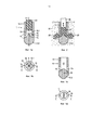
В соответствии с одним из аспектов изобретения предлагается медицинское устройство, например устройство, имплантируемое в кость человека или животного, или устройство для наращивания, обеспечивающее укрепление твердой ткани человека или животного для последующей имплантации отдельного имплантата. Предлагаемое устройство содержит оболочечный элемент, выполненный с возможностью контакта с живой твердой тканью и/или с заменяющим твердую ткань материалом при проведении хирургической операции. В качестве примера оболочечный элемент имеет в целом вытянутую форму и снабжен продольным отверстием, образующим продольный канал, идущий от проксимального конца оболочечного элемента в дистальном направлении, а также группой проходов в стенке указанного канала. По меньшей мере два из проходов могут иметь примерно одинаковое осевое расположение. Кроме того, устройство содержит разжижаемый элемент, вставляемый или вставленный в продольный канал и по меньшей мере частично разжижаемый под действием энергии, прикладываемой с проксимальной стороны таким образом, что разжиженный материал вытекает сквозь проходы в стенке наружу из продольного канала в структурные элементы твердой ткани и/или заменяющего твердую ткань материала. Медицинское устройство содержит также направляющую конструкцию, элементы которой расположены под углом к продольной оси продольного канала, так чтобы направлять разные части разжижаемого материала к разным проходам.In accordance with one aspect of the invention, there is provided a medical device, for example, a device implantable in a human or animal bone, or a device for building, providing for the strengthening of the solid tissue of a human or animal for subsequent implantation of a single implant. The proposed device contains a shell element made with the possibility of contact with living hard tissue and / or with a replacement hard tissue material during surgery. As an example, the shell element is generally elongated and provided with a longitudinal hole forming a longitudinal channel extending from the proximal end of the shell element in the distal direction, as well as a group of passages in the wall of the specified channel. At least two of the passages may have approximately the same axial arrangement. In addition, the device contains a liquefiable element, inserted or inserted into the longitudinal channel and at least partially liquefied by the energy applied from the proximal side so that the liquefied material flows through the passages in the wall outward from the longitudinal channel into the structural elements of the hard fabric and / or hard tissue replacement material. The medical device also includes a guide structure, the elements of which are located at an angle to the longitudinal axis of the longitudinal channel, so as to direct different parts of the liquefied material to different passages.
"Расположены под углом" - или азимутально - означает, что конструкция не одинакова по всей окружности и изменяется в зависимости от азимутального угла. При этом направляющая конструкция представляет собой конструкцию, находящуюся внутри поперечного сечения продольного отверстия - то есть, если поперечное сечение продольного отверстия имеет форму, например, круга, радиальное положение направляющей конструкции, по меньшей частично, находится в пределах радиуса отверстия.“Angled” - or azimuthally - means that the structure is not the same around the entire circumference and varies with the azimuthal angle. In this case, the guide structure is a structure located inside the cross section of the longitudinal hole — that is, if the cross section of the longitudinal hole has the shape of, for example, a circle, the radial position of the guide structure is at least partially within the radius of the hole.
Проходы в стенке оболочечного элемента (обычно в кольцеобразной стенке) могут быть распределены по окружности равномерно или асимметрично. Например, для некоторых вариантов использования предпочтительно, чтобы имелись два или три прохода на относительно небольших угловых расстояниях, от 30° до 120°, при этом чтобы другая сторона оболочечного элемента была выполнена без проходов.The passages in the wall of the shell element (usually in an annular wall) can be distributed evenly or asymmetrically around the circumference. For example, for some use cases, it is preferable that there are two or three passes at relatively small angular distances, from 30 ° to 120 °, with the other side of the shell element being made without passes.
Продольное отверстие можно выполнить по центру или со смещением относительно центра. Хотя для многих вариантов использования предпочтительным является центральное расположение, в случае асимметричных имплантатов (таких как стержень протеза) более предпочтительным может являться асимметричный выпуск. В частности, относительное расположение продольного отверстия может влиять на недействующий объем термопластического материала, остающегося в проходе - чем тоньше стенка в месте нахождения прохода, тем меньше глубина прохода и меньше недействующий объем.The longitudinal hole can be made in the center or offset from the center. Although a central location is preferred for many use cases, in the case of asymmetric implants (such as a prosthesis shaft), asymmetric release may be more preferred. In particular, the relative location of the longitudinal hole can affect the inactive volume of the thermoplastic material remaining in the passage — the thinner the wall at the location of the passage, the smaller the depth of passage and the smaller the inactive volume.
В качестве разжижаемого элемента можно использовать одиночный цельный элемент. Такой одиночный цельный элемента может быть предпочтительным при передаче механической энергии от проксимального к дистальному концу. Как вариант, можно использовать и группу разжижаемых элементов, например группу фасонных деталей, пластин, частиц или других подобных элементов.As a liquefied element, you can use a single solid element. Such a single integral element may be preferred when transmitting mechanical energy from the proximal to the distal end. Alternatively, you can use a group of fluidized elements, for example a group of shaped parts, plates, particles or other similar elements.
В медицинском устройстве, выполненном согласно данному принципу, разжижение происходит под воздействием энергии, поглощенной вблизи дистального конца разжижаемого элемента и вблизи проходов. Например, в качестве действующей энергии можно использовать энергию механической вибрации, при этом материал разжижаемого элемента можно разжижать на границе между разжижаемым элементом и направляющей структурой.In a medical device made according to this principle, liquefaction occurs under the influence of energy absorbed near the distal end of the liquefied element and near the aisles. For example, the energy of mechanical vibration can be used as the effective energy, while the material of the liquefied element can be liquefied at the boundary between the liquefied element and the guide structure.
Направляющая структура образована упорной поверхностью, к которой при разжижении прижимают дистальный конец разжижаемого элемента. Дистальная упорная поверхность для разжижаемого элемента может, например, закрывать продольный канал с дистальной стороны или по меньшей мере существенно уменьшать (например по меньшей мере на 50%) поперечное сечение продольного канала в дистальной части канала по сравнению с проксимальной частью.The guiding structure is formed by a thrust surface to which, at liquefaction, the distal end of the liquefied element is pressed. The distal abutment surface for the liquefiable element may, for example, close the longitudinal channel from the distal side or at least substantially reduce (for example at least 50%) the cross section of the longitudinal channel in the distal part of the channel compared to the proximal part.
Произвольное оставшееся поперечное сечение дистальной части продольного канала, идущей в дистальном направлении от направляющей конструкции, можно использовать, например, в качестве центральной (возможны также и варианты со смещением относительно центра) направляющей части или дистального прохода, сквозь который, в дополнение к проходам в стенке оболочечного элемента и в зависимости от глубины и диаметра такого дистального прохода, можно выдавливать части разжижаемого материала.An arbitrary remaining cross-section of the distal part of the longitudinal channel extending in the distal direction from the guide structure can be used, for example, as the central (also possible off-center options) guide part or distal passage through which, in addition to the passages in the wall shell element and depending on the depth and diameter of such a distal passage, you can squeeze out parts of the liquefied material.
Направляющая конструкция обеспечивает угловое распределение объема разжижаемого материала вблизи дистального конца разжижаемого элемента таким образом, чтобы направлять разные части разжижаемого материала к заданному из указанных проходов.The guide structure provides an angular distribution of the volume of the fluidized material near the distal end of the fluidized element in such a way as to direct different parts of the fluidized material to a predetermined of these passages.
Обнаружено, что такое решение решает потенциальную проблему, с которой сталкивались при использовании известных медицинских устройств: если ткань, прилегающая к разным проходам, значительно отличается в отношении пористости и/или твердости, появляется вероятность того, что большая часть разжижаемого материала выйдет сквозь то проход, на котором имеется минимальное сопротивление гидростатическому давлению на разжижаемый материал. В результате может возникнуть нежелательная анизотропия фиксации. Техническое решение согласно первому аспекту изобретения позволяет получить более однородное распределение разжижаемого материала между проходами.It was found that this solution solves the potential problem that was encountered when using known medical devices: if the tissue adjacent to different passages differs significantly in terms of porosity and / or hardness, it is likely that most of the liquefied material will escape through that passage, on which there is minimal resistance to hydrostatic pressure on the fluidized material. As a result, undesired fixation anisotropy may occur. The technical solution according to the first aspect of the invention allows to obtain a more uniform distribution of the fluidized material between the passages.
В некоторых вариантах осуществления изобретения направляющая конструкция содержит по меньшей мере одну стенку, проксимально выступающую из основной части направляющей структуры. Стенка разделяет на части объем дистальной области продольного отверстия, где происходит разжижение. При этом необязательно, чтобы стенка имела однородную толщину - достаточно, чтобы стенка просто обеспечивала угловое разделение между разными частями объема продольного канала, сообщающихся каждая с разными проходами, так чтобы обеспечить значительную тенденцию или даже принуждение частей разжижаемого материала, находящихся в разных частях объема, к выходу из продольного канала сквозь конкретный предназначенный для этого проход.In some embodiments of the invention, the guide structure comprises at least one wall proximal protruding from the main part of the guide structure. The wall divides into parts the volume of the distal region of the longitudinal opening, where liquefaction occurs. It is not necessary that the wall has a uniform thickness - it is enough that the wall simply provides an angular separation between different parts of the volume of the longitudinal channel, each communicating with different passages, so as to provide a significant tendency or even forcing parts of the liquefied material located in different parts of the volume to exit from the longitudinal channel through a specific passage intended for this.
Помимо обеспечения углового распределения, стенка используется также для направления энергии в места, где имеется тенденция к поглощению энергии вибрации и начинается разжижение. Это позволяет начинать разжижение над проходами ("над" в данном контексте относится к проксимальному направлению и не подразумевает конкретной ориентации во время использования) или по меньшей мере над их дистальным концом - таким образом можно уменьшить или предотвратить закупоривание проходов оставшимися твердыми частями.In addition to providing angular distribution, the wall is also used to direct energy to places where there is a tendency to absorb vibrational energy and liquefaction begins. This allows liquefaction to begin over passages (“above” in this context refers to the proximal direction and does not imply a specific orientation during use) or at least over their distal end — thus, clogging of the passages with remaining solid parts can be reduced or prevented.
В одном из вариантов осуществления изобретения направляющая конструкция содержит также наклонный элемент, проходящий под углом от продольной оси в направлении к дистальному концу соответствующего прохода, так что отсутствует выраженная граница между стенкой и упорной поверхностью. Наклонный элемент может быть изогнутым. Наклонный элемент может содержать радиусные геометрические элементы, отклоняющие разжижаемый материал с осевого в радиальном направлении внутри оболочечного элемента.In one embodiment, the guide structure also comprises an inclined element extending at an angle from the longitudinal axis towards the distal end of the corresponding passage, so that there is no pronounced boundary between the wall and the abutment surface. The inclined element may be curved. The inclined element may comprise radial geometric elements deflecting the liquefied material from the axial in the radial direction inside the shell element.
Стенка может в проксимальном направлении выходить за проксимальную сторону прохода - так, чтобы стенка удерживала весь материал, достигающий прохода, в соответствующем сегменте объема, предотвращая тем самым попадание материала к другой стенке под действием гидростатического давления и собственного движения. Указанные варианты осуществления особенно хорошо подходят для случаев, когда на разных проходах ожидается значительное различие сопротивлений вытеканию материала. В других вариантах осуществления стенка в проксимальном направлении не выходит за проксимальную сторону проходов, однако указанное направляющее действие обеспечивается и в этом случае. В предпочтительном варианте стенка выступает по меньшей мере на ![]()
![]()
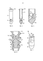
В первой группе вариантов осуществления изобретения направляющая конструкция представляет собой конструкцию оболочечного элемента, то есть ее основная часть выполнена как одно целое с оболочечным элементом или заранее жестко прикреплена к оболочечному элементу.In the first group of embodiments of the invention, the guiding structure is the structure of the shell element, that is, its main part is made integrally with the shell element or pre-rigidly attached to the shell element.
Во второй группе вариантов осуществления изобретения направляющая конструкция представляет собой направляющую конструкцию вставляемого по месту вставного элемента. В этом случае продольное отверстие оболочечного элемента может представлять собой сквозное отверстие, идущее от проксимального к дистальному концу. Дополнительно оболочечный элемент содержит стопорную конструкцию, взаимодействующую со вставным элементом при вставлении последнего с проксимальной стороны, что обеспечивает стопорение вставного элемента в заданном осевом положении и предотвращает его дальнейшее перемещение в дистальном направлении. В общем случае стопор получают за счет неоднородности сечения продольного отверстия по продольному направлению отверстия. Например, отверстие может содержать уступ, взаимодействующий с суживающейся дистальной частью вставного элемента с образованием посадки с натягом.In a second group of embodiments of the invention, the guide structure is a guide structure of a locally inserted insertion member. In this case, the longitudinal opening of the shell element may be a through hole extending from the proximal to the distal end. Additionally, the shell element contains a stopper structure interacting with the insertion element when the latter is inserted from the proximal side, which ensures the locking of the insertion element in a predetermined axial position and prevents its further movement in the distal direction. In the General case, the stopper is obtained due to the heterogeneity of the cross section of the longitudinal holes in the longitudinal direction of the hole. For example, the hole may comprise a step that interacts with the tapering distal portion of the insertion element to form an interference fit.
В вариантах осуществления второй группы предусмотрена возможность использования продольного отверстия в качестве канюляции, которую при проведении минимально инвазивной операции можно использовать для направления вводимого устройства.In embodiments of the second group, it is possible to use a longitudinal hole as a cannulation, which, when minimally invasive, is used to guide the input device.
Устройство согласно первому аспекту изобретения может представлять собой имплантат, такой как имплантат для фиксации. Такой имплантат может представлять собой костный винт и, в дополнение к средствам фиксации посредством разжиженного материала, может содержать резьбу. Как вариант, устройство может представлять собой имплантат, заменяющий костный винт. В более широком смысле изобретение относится к любому имплантату, предназначенному для фиксации в твердой ткани и/или в заменяющем твердую ткань материале.The device according to the first aspect of the invention may be an implant, such as an implant for fixation. Such an implant may be a bone screw and, in addition to means of fixation by means of a liquefied material, may comprise a thread. Alternatively, the device may be an implant replacing a bone screw. In a broader sense, the invention relates to any implant intended for fixation in hard tissue and / or in a tissue replacement material.
Как вариант, устройство согласно первому аспекту изобретения может представлять собой не имплантат, а устройство для наращивания, например, обеспечивающее наращивание слабой или непрочной твердой ткани и/или заменяющего твердую ткань материала, и затем удаляемое.Alternatively, the device according to the first aspect of the invention may not be an implant, but a device for building, for example, providing the growth of weak or fragile hard tissue and / or replacing hard tissue material, and then removed.
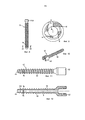
В зависимости от того, является ли устройство имплантатом или устройством для наращивания, соответствующим образом могут быть подобраны размеры стенок и/или проходов. Проходы со сравнительно большими поперечными сечениями подходят для обеспечения крепкого соединения между разжиженным и отвердевшим материалом, вытекшим сквозь проходы в структурные элементы твердой ткани и/или материала, заменяющий твердую ткань. Такое решение целесообразно использовать в случае, если устройство остается имплантированным, то есть является имплантатом. Проходы же со сравнительно малыми поперечными сечениями можно использовать для устройств наращивания - использовать меньшие поперечные сечения по меньшей мере в отношении размера по окружности; при этом при необходимости осевой размер может быть более значительным; например, проходы можно выполнить в виде удлиненных прорезей над более чем одним витком резьбы.Depending on whether the device is an implant or an extension device, the dimensions of the walls and / or passages can be appropriately selected. The passages with relatively large cross sections are suitable for providing a strong connection between the liquefied and hardened material flowing through the passages into the structural elements of the hard fabric and / or material that replaces the hard fabric. This solution is advisable to use if the device remains implanted, that is, it is an implant. Passages with relatively small cross sections can be used for building devices - use smaller cross sections at least with respect to circumference; however, if necessary, the axial size may be more significant; for example, passages can be made in the form of elongated slots over more than one thread.
Кроме того, при необходимости проходы могут быть не строго радиальными, то есть проходы могут быть выполнены асимметричными по отношению к повороту гильзового элемента вокруг продольной оси по часовой стрелке в сравнении с поворотом против часовой стрелки. Если гильзовый элемент, обладающий указанным признаком, также снабжен резьбой, это позволяет, при использовании с имплантатом, увеличить сопротивление отвинчиванию имплантата в случае, если сила, действующая на разжиженный и затем отвердевший материал, представляет собой не исключительно поперечную силу, но имеет и радиальную составляющую. При этом такой гильзовый элемент можно использовать и в съемном устройстве для наращивания, поскольку это способствует разделению между разжиженным материалом внутри оболочечного элемента и вытекшим из него разжиженным материалом.In addition, if necessary, the passages can be not strictly radial, that is, the passages can be made asymmetric with respect to the rotation of the sleeve element around the longitudinal axis clockwise in comparison with the rotation counterclockwise. If the sleeve element having the indicated feature is also threaded, this allows, when used with the implant, to increase the resistance to unscrewing the implant if the force acting on the liquefied and then hardened material is not only a transverse force, but also has a radial component . At the same time, such a sleeve element can also be used in a removable device for building, since this contributes to the separation between the liquefied material inside the shell element and the liquefied material leaked from it.
В некоторых вариантах осуществления изобретения устройство может представлять собой транспедикулярный фиксатор. Такой транспедикулярный фиксатор предназначен для использования аналогично транспедикулярному винту, то есть для имплантации в позвонок с дорсальной стороны (при этом в общем случае под углом к сагиттальной плоскости, немного по направлению внутрь к сагиттальной плоскости) сквозь ножку позвонка, с вхождением дистальной части устройства в тело позвонка. Проксимальная часть транспедиклярного фиксатора снабжена головкой для крепления ортопедической стяжки или иного приспособления, стабилизирующего позвоночный столб. Таким образом, транспедиклярный фиксатор содержит головку и штифт. Штифт выполнен с возможностью фиксации в позвонке, аналогично штифту транспедиклярного фиксатора (называемого также "ножкой"). Головку можно выполнить в виде любой из головок известных транспедиклярных фиксаторов, или же в соответствии с техническими требованиями новой системы стабилизации позвоночника. Основным требованием к головке является обеспечение прикрепления либо непосредственно к стяжке или к другому приспособлению, стабилизирующему позвоночника, либо к промежуточному приспособлению, к которому можно прикрепить стяжку (или другое приспособление, стабилизирующее позвоночник и/или другое промежуточное приспособление).In some embodiments, the device may be a transpedicular fixative. Such a transpedicular fixator is intended to be used similarly to a transpedicular screw, that is, for implantation into the vertebra from the dorsal side (in this case, generally at an angle to the sagittal plane, slightly inward towards the sagittal plane) through the leg of the vertebra, with the distal part of the device entering the body vertebra. The proximal part of the transpedicular fixator is equipped with a head for attaching an orthopedic screed or other device that stabilizes the spinal column. Thus, the transpedicular fixator comprises a head and a pin. The pin is made with the possibility of fixing in the vertebra, similar to the pin of the transpedicular fixator (also called the "leg"). The head can be made in the form of any of the heads of known transpedicular fixators, or in accordance with the technical requirements of the new spinal stabilization system. The main requirement for the head is to ensure attachment either directly to the screed or to another device that stabilizes the spine, or to an intermediate device to which the screed can be attached (or another device that stabilizes the spine and / or other intermediate device).
В некоторых вариантах осуществления транспедикулярный фиксатор представляет собой транспедикулярный винт, штифт которого снабжен резьбой, например резьбой с постоянным наружным диаметром (внешний диаметр), и внутренним диаметром (диаметр стержня), который больше на проксимальном конце по сравнению с дистальным концом. Внутренний диаметр может постепенно уменьшаться по всей длине резьбовой части или иметь ступенчатый профиль, или обладать любыми другими параметрами. Альтернативными вариантами осуществления изобретения предусмотрено постоянство внутреннего диаметра.In some embodiments, the transpedicular retainer is a transpedicular screw, the pin of which is provided with a thread, for example, a thread with a constant outer diameter (outer diameter), and an inner diameter (stem diameter), which is larger at the proximal end than the distal end. The inner diameter may gradually decrease over the entire length of the threaded part or have a stepped profile, or have any other parameters. Alternative embodiments of the invention provide for a constant inner diameter.
Некоторыми альтернативными вариантами осуществления изобретения предусмотрено отсутствие резьбы на штифте транспедикулярного фиксатора.Some alternative embodiments of the invention provide for the absence of thread on the pin of the transpedicular fixator.
В указанных вариантах осуществления изобретения штифт может иметь некруглое поперечное сечение. К примеру, штифт можно выполнить почти плоским, наподобие лезвия. В частности, в том месте, где штифт проникает внутрь ножки позвонка, его размер в продольном направлении может превышать его размер в поперечном направлении в соответствии с формой ножки позвонка. Такое некруглое сечение в случае необходимости позволяет придать дополнительную стабильность против скручивающих движений.In these embodiments, the pin may have a non-circular cross section. For example, the pin can be made almost flat, like a blade. In particular, in the place where the pin penetrates the vertebrae, its size in the longitudinal direction may exceed its size in the transverse direction in accordance with the shape of the vertebrae. Such a non-circular section, if necessary, allows you to give additional stability against twisting movements.
Отдельными вариантами осуществления изобретения предусмотрено использование закрученного штифта с некруглым поперечным сечением. Например, стержень может быть закручен примерно на четверть оборота, так чтобы плоскость лезвия на его дистальном конце примерно перпендикулярна плоскости лезвия на проксимальном конце. Например, часть, принимающая стяжку (или другое средство стабилизации позвоночного столба) можно ориентировать по отношению к закрученному штифту таким образом, чтобы плоскость лезвия на проксимальном конце штифта была приблизительно параллельна продольному направлению, а на дистальном конце штифта-приблизительно параллельна поперечному направлению (термины применимы к данной части описания и относятся к оси позвоночника). В вариантах осуществления второй группы, в которых штифт имеет не круглое, а почти плоское поперечное сечение, проходы снаружи от продольного отверстия могут, в частности, включать в себя каналы на обеих плоских сторонах. По меньшей мере на одной из малых сторон и/или на дистальном конце могут находиться дополнительные проходы. При выполнении хирургических операций может быть предпочтительным наличие на дистальном конце дополнительного аксиального прохода, поскольку оно позволит направлять вставляемый фиксатор посредством спицы Киршнера или аналогичного приспособления.Separate embodiments of the invention provide for the use of a twisted pin with a non-circular cross-section. For example, the shaft can be twisted about a quarter of a turn, so that the plane of the blade at its distal end is approximately perpendicular to the plane of the blade at the proximal end. For example, the part receiving the screed (or other means of stabilizing the spinal column) can be oriented relative to the twisted pin so that the plane of the blade at the proximal end of the pin is approximately parallel to the longitudinal direction, and at the distal end of the pin is approximately parallel to the transverse direction (terms apply to this part of the description and relate to the axis of the spine). In embodiments of the second group, in which the pin does not have a round, but almost flat cross-section, passages outside the longitudinal opening may, in particular, include channels on both flat sides. At least one of the small sides and / or at the distal end may have additional passages. When performing surgical operations, it may be preferable to have an additional axial passage at the distal end, since it will allow you to guide the insertable latch using a Kirchner needle or similar device.
Варианты осуществления устройств и способов в соответствии со всеми аспектами данного изобретения могут представлять собой устройства/способы, используемые в области хирургии человека или в области хирургии животных, в частности в области хирургии собак, кошек или других домашних животных.Embodiments of devices and methods in accordance with all aspects of the present invention may be devices / methods used in the field of human surgery or in the field of animal surgery, in particular in the field of surgery for dogs, cats or other domestic animals.
В некоторых вариантах осуществления проходы, сквозь которые разжиженный материал вытекает в процессе имплантации/наращивания, могут занимать одинаковое осевое положение или разные осевые положения. Угловые положения могут быть равномерно распределены по окружности. При наличии соответствующей необходимости отдельными вариантами осуществления предусмотрено отклонение угловых положений от равномерного распределения. Например, если имплантат предназначен для сращивания частей суставов и для вставления в суставную щель, проходы (если имеется более двух) могут быть размещены на противоположных сторонах, с обеспечением контакта с участками сустава.In some embodiments, the passages through which the liquefied material flows out during the implantation / build-up process may occupy the same axial position or different axial positions. Angular positions can be evenly distributed around the circumference. If appropriate, the individual variants of implementation provides for the deviation of the angular positions from a uniform distribution. For example, if the implant is designed to join parts of joints and to be inserted into the joint space, the passages (if there are more than two) can be placed on opposite sides, providing contact with areas of the joint.
В отдельных вариантах осуществления согласно любому аспекту изобретения или любому другому процессу фиксации или наращивания, предусматривающему выдавливание разжиженного материала из проходов в оболочечном элементе, может применяться многоуровневая фиксация или наращивание с последовательной фиксацией/наращиванием на разных уровнях, при этом каждому уровню соответствует по меньшей мере один выпускной проход (предпочтительно группа выпускных проходов). С этой целью, после фиксации/наращивания на первом уровне, вставной элемент (который может представлять собой первый вставной элемент, если сам оболочечный элемент содержит дистальную упорную поверхность, или может представлять собой второй вставной элемент, если для фиксации/наращивания на первом уровне уже был использован вставной элемент) вставляют с проксимальной стороны и стопорят в положении непосредственно под вторым уровнем. Затем снова запускают процесс разжижения. При необходимости указанные действия повторяют для третьего, четвертого, пятого и других последующих уровней.In certain embodiments, according to any aspect of the invention or any other fixing or expanding process, which extrudes the liquefied material from the passages in the shell element, a multi-level fixation or extension with sequential fixation / extension at different levels can be applied, with at least one corresponding to each level an outlet passage (preferably a group of outlet passages). For this purpose, after fixing / building on the first level, an insertion element (which may be the first insertion element if the shell element itself contains a distal abutment surface, or may be a second insertion element if, for fixing / building on the first level, used insertion element) is inserted from the proximal side and locked in position immediately below the second level. Then, the liquefaction process is started again. If necessary, these steps are repeated for the third, fourth, fifth and other subsequent levels.
В вариантах осуществления, в которых имплантат не имеет резьбы, внешняя форма имплантата (и/или устройства для наращивания), не обязательно является по существу цилиндрически круглой и может иметь любые очертания.In embodiments in which the implant is threadless, the external shape of the implant (and / or extension device) is not necessarily substantially cylindrical round and may have any shape.
Предпочтительно, чтобы механическая вибрация или колебания, используемые для устройств и способов согласно вариантам осуществления изобретения, предусматривающим разжижение полимера за счет теплоты трения, обусловленного механическими вибрациями, имели частоту в диапазоне от 2 до 200 кГц (более предпочтительно в диапазоне от 10 до 100 кГц или от 20 до 40 кГц), при удельной мощности колебаний от 0,2 до 20 Вт на квадратный миллиметр активной поверхности. Вибрирующий элемент (сонотрод) выполнен, например, таким образом, что его контактная поверхность колеблется в основном в направлении оси элемента (продольная вибрация) с амплитудой от 1 до 100 мкм, предпочтительно около 10 и 30 мкм. При этом возможны также и вращательные или радиальные колебания.Preferably, the mechanical vibration or vibrations used for devices and methods according to embodiments of the invention, providing for the dilution of the polymer due to the heat of friction due to mechanical vibrations, have a frequency in the range from 2 to 200 kHz (more preferably in the range from 10 to 100 kHz or from 20 to 40 kHz), with a specific power of oscillations from 0.2 to 20 W per square millimeter of active surface. The vibrating element (sonotrode) is made, for example, in such a way that its contact surface oscillates mainly in the direction of the axis of the element (longitudinal vibration) with an amplitude of from 1 to 100 microns, preferably about 10 and 30 microns. In this case, rotational or radial vibrations are also possible.
В отдельных вариантах осуществления используется дополнительный способ производства тепловой энергии для получения необходимого разжижения, предусматривающий подачу электромагнитного излучения в одну из частей имплантируемого устройства, причем одна из частей устройства способна поглощать электромагнитное излучение, причем поглощение происходит предпочтительно внутри предназначенного к разжижению фиксирующего материала или в непосредственной к нему близости. Предпочтительно использовать электромагнитное излучение видимого или инфракрасного диапазона, причем предпочтительным источником излучения является соответствующий лазер. Возможен также электрический нагрев одной из частей устройства.In some embodiments, the implementation uses an additional method of producing thermal energy to obtain the necessary liquefaction, which provides for the supply of electromagnetic radiation to one of the parts of the implantable device, moreover, one of the parts of the device is capable of absorbing electromagnetic radiation, the absorption taking place preferably inside the fixing material to be liquefied or in direct contact with proximity to him. It is preferable to use electromagnetic radiation of the visible or infrared range, with the corresponding laser being the preferred radiation source. Electric heating of one of the parts of the device is also possible.
В контексте данного описания термин "термопластичный материал, разжижаемый, например, путем механической вибрации", или кратко "разжижаемый термопластичный материал" или "разжижаемый материал", использован для описания материала, содержащего по меньшей мере один термопластичный компонент и становящегося жидким или текучим при нагреве, в частности при нагреве трением, то есть при размещении на одной из двух поверхностей (контактных поверхностей), находящихся в контакте друг с другом и приводимых в колебательное или вращательное движение относительно друг друга с частотой колебаний в диапазоне от 2 кГц до 200 кГц, предпочтительно от 20 до 40 кГц и с амплитудой в диапазоне от 1 мкм до 100 мкм, предпочтительно от 10 до 30 мкм. Такие колебания можно получить, например, посредством известных ультразвуковых устройств, например стоматологических. Для образования силового соединения с тканью материал при введении должен иметь коэффициент упругости более 0,5 ГПа, предпочтительно более 1 ГПа. Коэффициент упругости, равный по меньшей мере 0,5 ГПа, также обеспечивает способность разжижаемого материала к передаче ультразвуковых колебаний со столь малым затуханием, что не происходит внутреннее разжижение и соответственно дестабилизация разжижаемого элемента, то есть разжижение происходит лишь в том месте, где разжижаемый материал находится на границе разжижения на опорной поверхности. Предпочтительно, чтобы значения температуры пластификации достигали 200°С, находились в диапазоне между 200°С и 300°С или даже превышали 300°С. В зависимости от применения разжижаемый термопластичный материал может обладать или не обладать способностью к рассасыванию.In the context of this description, the term "thermoplastic material, liquefied, for example, by mechanical vibration", or briefly "liquefied thermoplastic material" or "liquefied material", is used to describe a material containing at least one thermoplastic component and becomes liquid or fluid when heated , in particular, when heated by friction, that is, when placed on one of two surfaces (contact surfaces) that are in contact with each other and brought into oscillatory or rotational motion relative to each other with an oscillation frequency in the range from 2 kHz to 200 kHz, preferably from 20 to 40 kHz and with an amplitude in the range from 1 μm to 100 μm, preferably from 10 to 30 μm. Such oscillations can be obtained, for example, by known ultrasonic devices, for example dental. To form a force connection with the tissue, the material must have an elastic coefficient of more than 0.5 GPa, preferably more than 1 GPa, when introduced. An elastic coefficient of at least 0.5 GPa also provides the ability of the fluid to transmit ultrasonic vibrations with such low attenuation that there is no internal liquefaction and therefore destabilization of the liquefied element, that is, the liquefaction occurs only at the place where the liquefied material is located on the boundary of the liquefaction on the supporting surface. Preferably, the plasticization temperature reaches 200 ° C, is in the range between 200 ° C and 300 ° C, or even exceeds 300 ° C. Depending on the application, the liquefied thermoplastic material may or may not be resorbable.
Подходящими рассасывающимися полимерами являются, например, материалы на основе молочной кислоты и/или гликолиевой кислоты (полимолочная кислота (PLA), поли-L-молочная кислота (PLLA), полигликолевая кислота (PGA), полилактогликолевая кислота (PLGA) и другие аналогичные) или полигидроксидалконаты (РНА), поликапролакторы (PCL), полисахариды, полидиоксаноны (PD), полиангидриды, полипептиды или соответствующие сополимеры, смешанные полимеры, композитные материалы, содержащие указанные полимеры в качестве компонентов. В качестве не рассасывающихся полимеров подходят термопластики, такие как полиолефины, полиакрилаты, полиметилкрилаты, поликарбонаты, полиамиды, полиэстираты, полиуретаны, полисульфоны, полиарилкетоны, полиимиды, полифенил сульфиды или жидкие кристаллические полимеры (LCPS), полиацетаты, галогенированые полимеры, в частности, галогенированные полиолефины, полифенилен сульфиды, полисульфоны, полиэфиры, полипропилены (РР), или соответствующие сополимеры, смешанные полимеры или композитные материалы, содержащие указанные полимеры в качестве компонентов. К примерам подходящего термопластичного материала относятся любые полилактидные материалы LR708 (аморфный поли(L-DL)лактид 70/30), L209 или L210S компании Bohringer Ingelheim.Suitable resorbable polymers are, for example, materials based on lactic acid and / or glycolic acid (polylactic acid (PLA), poly-L-lactic acid (PLLA), polyglycolic acid (PGA), polylactoglycolic acid (PLGA) and other similar) or polyhydroxylalkonates (PHA), polycaprolactors (PCL), polysaccharides, polydioxanones (PD), polyanhydrides, polypeptides or the corresponding copolymers, mixed polymers, composite materials containing these polymers as components. Non-absorbable polymers are suitable thermoplastics such as polyolefins, polyacrylates, polymethyl acrylates, polycarbonates, polyamides, polyesters, polyurethanes, polysulfones, polyaryl ketones, polyimides, polyphenyl sulfides or liquid crystalline polymers (LCPS), polyacetates, halogenated polymers, polyphenylene sulfides, polysulfones, polyesters, polypropylene (PP), or the corresponding copolymers, mixed polymers or composite materials containing these polymers as ve components. Examples of suitable thermoplastic materials include any polylactide materials LR708 (amorphous poly (L-DL) lactide 70/30), L209 or L210S from Bohringer Ingelheim.
Частными примерами разлагающихся материалов являются полилактиды, такие как полимеры LR706 PLDLLA 70/30, R208 PLDLA 50/50, L210S, и PLLA 100% L, все компании Böhringer. Перечень подходящих разлагающихся полимерных материалов можно найти также в работе Винтермантеля (Erich Wintermantel и Suk-Woo Наа) "Медицинская техника и технологии с использованием биосовместимых материалов" ("Medizinaltechnik mit biokompatiblen Materialien und Verfahren"), издательство Шпрингер, Берлин 2002 (в дальнейшем "Винтермантель"), стр. 200; информация по кислотам PGA и PLA приведена на стр. 202 и далее, по поликапролакторам (PCL) см. стр. 207, по сополимерам PHB-PHV - стр. 206; по полидиоксанону (PDS) - стр. 209. Описание других само-рассасывающихся материалов можно найти, например в работе СА Bailey и др., журнал Hand Surg [Бр.] 2006 апрель; 31 (2): 208-12.Particular examples of degradable materials are polylactides, such as LR706 PLDLLA 70/30, R208 PLDLA 50/50, L210S, and PLLA 100% L polymers, all from Böhringer. A list of suitable degradable polymeric materials can also be found in Wintermantel (Erich Wintermantel and Suk-Woo Naa), Medical Technology and Technology Using Biocompatible Materials (Medizinaltechnik mit biokompatiblen Materialien und Verfahren), Springer, Berlin 2002 (hereinafter " Wintermantel "), p. 200; information on PGA and PLA acids is given on page 202 onwards, for polycaprolactors (PCL) see page 207, for PHB-PHV copolymers - page 206; for polydioxanone (PDS), p. 209. A description of other self-absorbable materials can be found, for example, in the work of SA Bailey et al., Hand Surg magazine [Br.] 2006 April; 31 (2): 208-12.
Частными примерами неразлагающихся материалов являются: полиэфиркетон (PEEK Optima марки 450 и 150, компания Invibio Ltd), полиэфиримид, полиамид 12, полиамид 11, полиамид 6, полиамид 66, поликарбонат, полиметилметакрилат, полиоксиметилен или поликарбонатуретан (в частности, Bionate® компании DSM, в особенности Bionate 75D и Bionate 65D; соответствующая информация представлена в описаниях, находящихся в открытом доступе, например на сайте www.matweb.com компании Automation Creations, Inc.). Обзорная таблица полимеров и их применений приведены у Винтермантеля на стр. 150; конкретные примеры можно найти у Винтермантеля на стр. 161 и далее (фикоэритрин (РЕ), Hostalen Gur 812 компании Höchst AG), стр. 164 и далее полиэтилентерефталат (PET), стр. 169 и далее (полиамид (РА), а именно полиамид (РА) 6 и полиамид (РА) 66), 171 и далее политетрафторэтилен (PTFE), 173 и далее поли(n-метил)метакрилимид (РММА), стр. 180 (полиуретан (PUR), см. таблицу), стр. 186 и далее полиэфирэфиркетон (РЕЕK), стр. 189 и далее полисульфон (PSU), стр. 191 и далее (РОМ - полиацетал, торговые названия Delrin, Tenac, также применялся в эндопротезах Protec).Particular examples of non-degradable materials are: polyetherketone (PEEK Optima grades 450 and 150, Invibio Ltd), polyetherimide,
Разжижаемый материал, обладающий термопластичными свойствами, может содержать примеси или соединения другого назначения. В частности, термопластичные материалы могут быть усилены добавлением присадок, в частности присадок, обеспечивающих терапевтическое или иное необходимое воздействие. Термопластический материал может также содержать компоненты, которые расширяются и растворяются (образуют поры) по месту (например, полиэфиры, полисахариды, гидрогели, фосфаты натрия) или соединения, освобождаемые по месту и обладающие терапевтическим действием, например способствующие заживлению и регенерации (например стимуляторы роста, антибиотики, противовоспалительные средства или буферные вещества, такие как фосфат натрия или карбонат кальция, препятствующие вредным эффектам разложения кислот). Если термопластичный материал является рассасывающимся, выделение таких соединений происходит с задержкой.The liquefied material having thermoplastic properties may contain impurities or compounds of other purposes. In particular, thermoplastic materials can be enhanced by the addition of additives, in particular additives, providing a therapeutic or other necessary effect. The thermoplastic material may also contain components that expand and dissolve (form pores) locally (for example, polyesters, polysaccharides, hydrogels, sodium phosphates) or compounds that are released locally and have a therapeutic effect, for example, promote healing and regeneration (e.g. growth stimulants, antibiotics, anti-inflammatory drugs, or buffers such as sodium phosphate or calcium carbonate, which prevent the harmful effects of acid decomposition). If the thermoplastic material is absorbable, the release of such compounds occurs with a delay.
Если разжижение разжижаемого материала осуществляют не с помощью энергии вибраций, а под действием электромагнитного излучения, то в отдельных местах материал может содержать соединения (в виде частиц или молекул), способные поглощать излучение в определенном диапазоне частот (в частности, видимое и инфракрасное излучение), например фосфаты кальция, карбонаты кальция, фосфаты натрия, оксиды титана, слюду, насыщенные жирные кислоты, полисахариды, глюкозу или их смеси.If the liquefaction of the liquefied material is carried out not with the help of vibrational energy, but under the influence of electromagnetic radiation, then in some places the material may contain compounds (in the form of particles or molecules) that can absorb radiation in a certain frequency range (in particular, visible and infrared radiation), for example, calcium phosphates, calcium carbonates, sodium phosphates, titanium oxides, mica, saturated fatty acids, polysaccharides, glucose, or mixtures thereof.
К используемым наполнителям относятся разлагаемые стимуляторы остеогенеза для использования в разлагаемых полимерах, в том числе: β-трикальций фосфат (TCP), гидроксиапатит (НА, кристалличность <90%, или смеси фосфата (TCP), гидроксиапатита (НА), DHCP, биокерамики (см. Винтермантель). К стимулирующим остеогенез наполнителям для неразлагаемых полимеров, которые являются только частично или трудно разлагаемыми, относятся: биокерамика, гидроксиапатит (кристалличность >90%), НАРЕХ®, см. SM Rea и др., журнал Mater Sci Mater Med. 2004 сентябрь; 15 (9): 997-1005; по гидроксиапатитам см. L. Fang и др., Biomaterials 2006 июль; 27 (20): 3701-7, М. Huang и др., журнал Mater Sci Mater Med 2003 июль; 14 (7): 655-60, а также W. Bonfield и E. Tanner, Materials World 1997 январь; №1: 18-20. Варианты биоактивных наполнителей и их обсуждение приведены, например, в работе X. Huang и X. Miao, журнал Biomater Арр. 2007 апрель; 21 (4): 351-74), JA Juhasz и др. Biomaterials, 2004 март; 25 (6): 949-55. К частным вариантам наполнителей относятся: крупнозернистые 5-20 мкм (предпочтительное объемное содержание 10-25%), сверхтонкие (нанонаполнители из осаждения, предпочтительно пластинчатые с аспектным отношением >10, 10-50 нм, объемное содержание от 0,5 до 5%).Excipients used include degradable osteogenesis stimulants for use in degradable polymers, including: β-tricalcium phosphate (TCP), hydroxyapatite (HA, crystallinity <90%, or a mixture of phosphate (TCP), hydroxyapatite (HA), DHCP, bioceramics ( see Wintermantel.) Osteogenesis-stimulating excipients for non-degradable polymers that are only partially or difficult to decompose include bioceramics, hydroxyapatite (crystallinity> 90%), NAPEX®, see SM Rea et al., Mater Sci Mater Med. 2004 September; 15 (9): 997-1005; by hydroxyapatite m. see L. Fang et al., Biomaterials 2006 July; 27 (20): 3701-7, M. Huang et al., Mater Sci Mater Med 2003 July; 14 (7): 655-60, as well as W Bonfield and E. Tanner, Materials World 1997 January; No. 1: 18-20. Variants of bioactive fillers and their discussion are given, for example, in the work of X. Huang and X. Miao, Biomater Arpr. 2007 April; 21 (4) : 351-74), JA Juhasz et al. Biomaterials, March 2004; 25 (6): 949-55. Particular options for fillers include: coarse-grained 5-20 microns (preferred volumetric content of 10-25%), ultrafine (nanofillers from deposition, preferably lamellar with an aspect ratio> 10, 10-50 nm, volumetric content from 0.5 to 5%) .
В качестве испытуемого материала использовался полимер PLDLA 70/30, содержащий 30% (по весу) двухфазного фосфата кальция, который показал особенно выигрышные характеристики разжижения.The PLDLA 70/30 polymer containing 30% (by weight) of biphasic calcium phosphate, which showed especially advantageous liquefaction characteristics, was used as the test material.
В качестве материала оболочечного элемента (например, винта) можно использовать любой материал с температурой плавления выше температуры разжижаемого материала. В частности, оболочечный элемент может представлять собой металл, например титановый сплав. Предпочтительным материалом является титан 5 класса. Указанный материал, помимо того, что он в целом подходит для использования в имплантируемых приспособлениях, обладает сравнительно малой теплопроводностью. За счет плохой теплопроводности происходит быстрый нагрев области плавления, образующейся в разжижаемом материале и на границе с направляющей конструкцией, при этом не происходит нагрева окружающих областей до слишком высоких температур. В качестве альтернативных материалов для оболочечного элемента можно использовать и другие металлы, например другие сплавы титана, нержавеющую сталь, керамические материалы, такие как оксиды циркония или оксиды алюминия, или твердые пластмассы, такие как полиэфирэфиркетон (РЕЕK) и другие аналогичные материалы.As the material of the shell element (for example, a screw), any material with a melting point higher than the temperature of the liquefied material can be used. In particular, the shell element may be a metal, for example a titanium alloy. The preferred material is grade 5 titanium. The specified material, in addition to being generally suitable for use in implantable devices, has a relatively low thermal conductivity. Due to poor thermal conductivity, the melting region formed in the fluidized material and at the boundary with the guide structure is rapidly heated, while the surrounding areas do not heat up to too high temperatures. Other metals, such as other titanium alloys, stainless steel, ceramic materials such as zirconium oxides or aluminum oxides, or hard plastics such as polyetheretherketone (PEEK) and other similar materials, can be used as alternative materials for the shell element.
КРАТКОЕ ОПИСАНИЕ ЧЕРТЕЖЕЙBRIEF DESCRIPTION OF THE DRAWINGS
Способы осуществления изобретения и варианты его осуществления описаны ниже со ссылками на чертежи, представляющие по существу схематические изображения. Одинаковые номера позиций на чертежах относятся к одинаковым или аналогичным элементам, при этом:Methods of carrying out the invention and variants of its implementation are described below with reference to the drawings, representing essentially schematic images. The same item numbers in the drawings refer to the same or similar elements, wherein:
фиг. 1а и 1b - один вариантов осуществления имплантата или устройства для наращивания;FIG. 1a and 1b show one embodiment of an implant or extension device;
фиг. 1с и 1d - дистальная часть указанного варианта;FIG. 1c and 1d - the distal part of the specified option;
фиг. 2 - поперечное сечение устройства с фиг. 1а и 1b при проведении имплантации или наращивания;FIG. 2 is a cross section of the device of FIG. 1a and 1b during implantation or extension;
фиг. 3-5 - один из вариантов осуществления оболочечного элемента имплантата или устройства для наращивания;FIG. 3-5 - one of the embodiments of the shell element of the implant or device for building;
фиг. 6 - частичный вид еще одного варианта осуществления имплантата или устройства для наращивания;FIG. 6 is a partial view of yet another embodiment of an implant or extension device;
фиг. 7 - изображение вставного элемента имплантата или устройства для наращивания с фиг. 6;FIG. 7 is a view of an insert element of an implant or extension device of FIG. 6;
фиг. 8 и 9 - еще один вариант осуществления оболочечного элемента;FIG. 8 and 9 are another embodiment of a shell element;
фиг. 10-12 - транспедикулярный винт, представляющий собой еще один вариант осуществления оболочечного элемента и один из вариантов осуществления транспедикулярного фиксатора.FIG. 10-12 is a transpedicular screw, which is another embodiment of a shell element and one embodiment of a transpedicular fixative.
ОПИСАНИЕ ПРЕДПОЧТИТЕЛЬНЫХ ВАРИАНТОВ ОСУЩЕСТВЛЕНИЯDESCRIPTION OF PREFERRED EMBODIMENTS
Устройство, схематически показанное на фиг.1а и 1b, может представлять собой хирургический имплантат, например имплантат, фиксируемый в твердой ткани и/или в заменяющем твердую ткань материале. Устройство может выполнять функцию, аналогичную хирургическому винту и/или фиксатору (такому как фиксатор хирургической нити или имплантат под установку зубной коронки), или "самостоятельную" функцию, например вместилища вещества, подаваемого в окружающую ткань, и/или вместилища другого устройства, например электронного устройства, или другую сходную функцию. Как и во всех иных вариантах осуществления, устройство, если оно предназначено оставаться после хирургической операции в теле пациента, может выполнять любую функцию хирургического устройства, фиксируемого в твердой ткани и/или в заменителе твердой ткани, и используемого в хирургии. В качестве альтернативы устройству, остающемуся в теле пациента после хирургической операции, предусмотрены другие варианты осуществления изобретения, которые, если явным образом не указано иное, могут представлять собой временный фиксатор или устройство для наращивания - например, аналогичные описанным ниже.The device schematically shown in FIGS. 1a and 1b may be a surgical implant, for example, an implant that is fixed in hard tissue and / or in a tissue replacing hard tissue material. The device can perform a function similar to a surgical screw and / or fixative (such as a surgical floss fixer or an implant for the installation of a dental crown), or an "independent" function, for example, a container of a substance supplied to the surrounding tissue, and / or a container of another device, for example, an electronic device, or other similar function. As in all other embodiments, the device, if it is intended to remain after the surgery in the patient’s body, can fulfill any function of the surgical device, which is fixed in hard tissue and / or as a substitute for hard tissue, and used in surgery. As an alternative to the device remaining in the patient’s body after surgery, other embodiments of the invention are provided which, unless expressly stated otherwise, may be a temporary fixative or extension device — for example, similar to those described below.
Устройство 1 можно устанавливать внутри отверстия, щели или другой полости в твердой ткани и/или в заменяющем твердую ткань материале по существу путем перемещения вдоль оси 3 имплантации, соответствующей также продольной оси устройства. Устройство содержит оболочечный элемент 11 с проксимальной частью 11.1 стенки, окружающей продольное отверстие 13, открытое с проксимальной стороны оболочечного элемента. С дистальной стороны продольное отверстие ограничено дистальной концевой частью 11.2. Дистальная концевая часть образует направляющую конструкцию, содержащую вогнутый наклонный элемент 12, отходящий под углом от центра и расположенный вокруг продольной оси. Радиально снаружи наклонного элемента на части стенки оболочечного элемента имеются четыре прохода 14, равномерно распределенные по окружности оболочечного элемента. Кроме того, направляющая конструкция содержит стенки 15, расположенные под углом между указанными проходами и делящие часть пространства продольного отверстия, сообщающуюся с проходами 14, на угловые сектора. В показанном варианте стенки не имеют постоянной толщины и сужаются к проксимальному краю 15.1.The
Кроме того, устройство содержит разжижаемый элемент 21 в виде полимерного стержня 21, выполненного под установку с проксимальной стороны внутрь продольного отверстия 13 оболочечного элемента.In addition, the device contains a liquefied
При выполнении фиксации или наращивания разжижаемый элемент 21 вставляют и устанавливают впритык с направляющей конструкцией. При нахождении оболочечного элемента в контакте с твердой тканью и/или с заменяющим твердую ткань материалом 31, разжижаемый элемент прижимают к направляющей конструкции, прикладывая с проксимальной стороны энергию. Под дополнительным воздействием прижимающего усилия разжиженный материал разжижаемого элемента выдавливается сквозь проходы 14 внутрь таких структурных элементов, как поры, неровности и неоднородности поверхности или другие структурные элементы твердой ткани и/или заменяющего твердую ткань материала 31.When performing fixation or extension, the liquefied
Вариант оболочечного элемента с фиг. 1с и 1d имеет следующие признаки, отличающие его от описанной выше конструкции:The embodiment of the cladding element of FIG. 1c and 1d has the following features that distinguish it from the design described above:
a) вместо четырех проходов 14 на круговой стенке имеются только два указанных прохода 14; при этом направляющая конструкция имеет соответствующую форму; если направляющая конструкция симметрична, то имеет симметрию второго порядка, а не четвертого порядка как на фиг. 1а и 1b;a) instead of four
b) наклонный элемент 12 направляющей конструкции выполнен не вогнутым, а по существу плоским;b) the
c) проходы 14 выполнены не круглыми или по существу круглыми, а вытянутыми - в изображенном варианте размер по оси значительно больше размера по окружности;c) the
d) направляющая конструкция снабжена с дистальной стороны дополнительным осевым проходом 19; первым преимуществом такого дистального прохода является возможность его использования в качестве направляющего элемента - при выполнении хирургической операции тонкий хирургический элемент, такой как спица Киршнера, можно направлять к заданной точке, с временным закреплением в ней дистального конца; затем оболочечный элемент можно поместить в нужное положение путем смещения на указанном тонком элементе, после чего тонкий элемент можно удалить; вторым преимуществом является возможность дополнительной дистальной фиксации путем выдавливания разжиженного разжижаемого материала также из дистального прохода 19, с последующим вдавливанием его в структурные элементы ткани вокруг выхода дистального прохода.d) the guide structure is provided on the distal side with an additional
Все указанные технические признаки могут присутствовать как сочетании (как показано на фиг. 1с и 1d), так и по отдельности (например в конструкции с фиг.1а, 1b можно предусмотреть дистальный проход 19 с четырьмя проходами, без изменения направляющей конструкции, или другие варианты). Указанные признаки могут быть включены в любом неполном сочетании (например, конструкцию с фиг. 1а, 1b можно модифицировать таким образом, чтобы она имела два прохода, симметрию второго порядка и дополнительный дистальный проход, при этом направляющая конструкция может быть вогнутой, проходы иметь приблизительно круглую форму, возможны и другие сочетания признаков.All these technical features may be present both in combination (as shown in FIGS. 1c and 1d), or separately (for example, in the design of FIGS. 1a, 1b, a
В зависимости от технических условий, дополнительный дистальный проход 19 (при наличии) можно выполнить с возможностью выдавливания сквозь него разжиженного материала или без такой возможности. Как правило, чем больше диаметр и чем меньше глубина, тем сильнее тенденция к выдавливанию разжиженного материала. Кроме того, имеет значение количество материала оболочечного элемента вокруг дистального прохода 19, участвующего в охлаждении материала в дистальном проходе. В качестве разжижаемого элемента оболочечного элемента, аналогичного показанному на фиг. 1с и выполненному из титана, использован стержень из PLDLA. При дистальном проходе 19 с диаметром 1,7 мм и длиной 3 мм в ряде экспериментов сквозь дистальный проход наблюдался выход небольшого количества разжиженного материала, при этом в других экспериментах материал застывал в проходе. Таким образом, для имплантатов такого типа можно считать пороговым соотношение d/1 (диаметр/длина), равное 1,7/3. Бòльшие диаметры или меньшие глубины обеспечивают надежный выход материала из дистального прохода, а меньшие диаметры или существенно бòльшие глубины позволяют надежно предотвратить вытекание за счет того, что во время процесса материал застывает в проходе.Depending on the technical conditions, an additional distal passage 19 (if any) can be made with the possibility of extruding liquefied material through it or without such a possibility. As a rule, the larger the diameter and the smaller the depth, the stronger the tendency to extrude liquefied material. In addition, the amount of material of the shell element around the
Указанное точное соотношение справедливо для формы с фиг. 1с, при этом тот же принцип относится и к другим формам.The indicated exact ratio is valid for the form of FIG. 1c, while the same principle applies to other forms.
Дистальный проход, аналогичный показанному на фиг. 1с, не обязательно выполнен цилиндрическим и может иметь другую форму, в том числе с элементами неправильной формы, выступающими из стенки внутрь дистального прохода.A distal passage similar to that shown in FIG. 1c is not necessarily cylindrical and may have a different shape, including with irregularly shaped elements protruding from the wall into the distal passage.
Если дистальный проход выполнен с размерами, обеспечивающими вытекание материала, а хирург желает предотвратить вытекание материала в дистальном направлении, дистальный проход можно закрыть обычной затычкой.If the distal passage is made with dimensions that allow the material to flow out, and the surgeon wants to prevent the material from flowing out in the distal direction, the distal passage can be closed with a regular plug.
В общем случае оболочечный элемент в соответствии с изобретением может обладать любым из признаков или любым сочетанием признаков a-d. Вместо признака а в устройстве может иметься любое количество проходов. Как показано на фиг. 2, предпочтительным способом подачи энергии является использование сонотрода 35, прижимаемого к проксимальному торцу разжижаемого элемента, при этом на сонотрод подается механическая вибрация. Механическая вибрация подается в разжижаемый элемент 21, при этом энергия колебаний по меньшей мере частично поглощается на границе с направляющей конструкцией, что приводит по меньшей мере к частичному разжижению полимерного материала разжижаемого элемента на указанной границе. Угловое расположение стенок направляющей конструкции между проходами позволяет, во-первых, разделять разжижаемый элемент на части в процессе разжижения. Благодаря этому из каждого из четырех проходов 14 выдавливается примерно одинаковое количество разжиженного материала, даже если при выдавливании через различные проходы 14 разжиженный материал встречает разное сопротивление. Во-вторых, стенки 15, дистально выступающие из корпуса направляющей конструкции и опорной поверхности, обеспечивают направление энергии. Под действием механической вибрации разжижаемый материал имеет свойство сначала разжижаться на краях или на других выраженных частях либо оболочечного элемента либо самого разжижаемого элемента. В результате направления стенками 15 энергии разжижение будет начинаться и происходить вблизи проходов 14, а не, например, на проксимальной границе контакта с сонотродом, где слишком раннее начало разжижения было бы нежелательным.In the General case, the shell element in accordance with the invention may have any of the features or any combination of features a-d. Instead of the sign of a, the device may have any number of passes. As shown in FIG. 2, the preferred method of supplying energy is to use a
На фиг. 2 показана ситуация, когда в процессе фиксации или наращивания оболочечный элемент вставлен в отверстие, предварительно выполненное в костной ткани 31. Разжиженные и затвердевающие части 22 материала, вдавленные в окружающую костную ткань 31 и проникающие вглубь ее структурных элементов, укрепляют тем самым ткань, которая может представлять собой губчатое вещество кости или соответствующий заменяющий материал. При этом, если устройство является имплантатом, оставляемым в теле пациента, то части разжиженного материала остаются после затвердевания в оболочечном элементе, и такое соединение обеспечивает прочную фиксацию.In FIG. Figure 2 shows the situation when, during the process of fixation or extension, the shell element is inserted into the hole previously made in the
На фиг. 3-5 представлены различные виды другого варианта оболочечного элемента заявленного устройства. Помимо признаков оболочечного элемента 11, описанного в связи с фиг. 1а, 1b и 2, оболочечный элемент 11 содержит следующие признаки:In FIG. 3-5 are various views of another embodiment of a shell element of the claimed device. In addition to the features of the
e) фланец 11.3, используемый, например, для крепления другого, не показанного здесь элемента к твердой ткани и/или к заменяющему твердую ткань материалу;e) a flange 11.3 used, for example, for attaching another element, not shown here, to a hard fabric and / or to a material that replaces a hard fabric;
f) увеличен осевой (относительно продольной оси) размер проходов 14, так что в проксимальном направлении проходы 14 проходят дальше краев 15.1 стенок 15 - такое увеличение осевого размера особенно подходит для устройств, оставляемых в теле пациента, поскольку таким образом обеспечивается большая область контакта между частями разжиженного материала, проникающего внутрь ткани и частями материала, остающимися в оболочечном элементе;f) the axial (relative to the longitudinal axis) size of the
g) стенки 15 имеют участок постоянной толщины, заканчивающийся на краях 15.1;g) the
h) наклонный элемент 12 имеет не сферическую, а коническую форму, поэтому сечение указанного элемента плоскостью, проходящей через продольную ось, представляет собой прямую, а не вогнутую линию;h) the
i) края 15.1 стенок 15 наклонены в направлении центра.i) the edges 15.1 of the
Указанные признаки могут присутствовать как все вместе (как в варианте с фиг. 3-5), так и по отдельности, или в любом промежуточном сочетании с признаками a-d, за исключением того, что признаки b и h относятся к (альтернативным) формам наклонного элемента.These signs can be present both collectively (as in the embodiment of Figs. 3-5), or separately, or in any intermediate combination with signs ad, except that signs b and h relate to (alternative) forms of the inclined element .
Форма стенок и наклонного элемента в вариантах с фиг.3-5 обеспечивает преимущества, относящиеся к изготовлению оболочечного элемента. В частности, оболочечный элемент можно изготовить, высверлив в стержневой заготовке продольное отверстие, а затем высверлив под острым углом проходы 14. При этом можно использовать дрель с коническим наконечником, перемещаемую вверх и вниз в процессе получения проходов 14 удлиненной формы. Разумеется, что оболочечный элемент 11 с фиг. 3-5, равно как и оболочечные элементы, выполненные в соответствии с другими вариантами осуществления изобретения, не могут быть ограничены конкретными способами их изготовления. Напротив, для получения оболочечного элемента можно использовать и другие способы изготовления, в том числе способы механической обработки, а также литья. Квалифицированный специалист знает и/или сможет найти множество публикаций, относящихся к изготовлению, например, медицинских устройств из титана или других металлов, керамики, твердых пластмасс или других подходящих материалов.The shape of the walls and the inclined element in the embodiments of FIGS. 3-5 provides advantages related to the manufacture of the shell element. In particular, the shell element can be made by drilling a longitudinal hole in the core blank and then drilling the
На фиг. 6 и 7 показан еще один вариант осуществления медицинского устройства. По сравнению с описанными выше, вариант с фиг. 6 и 7 обладает следующими признаками:In FIG. 6 and 7 show another embodiment of a medical device. Compared to those described above, the embodiment of FIG. 6 and 7 has the following features:
j) на внешней стороне оболочечного элемента выполнена наружная резьба 11.4;j) an external thread 11.4 is made on the outside of the shell element;
k) продольное отверстие 13 является сквозным, что позволяет посредством спицы направлять устройство при выполнении минимально инвазивной хирургии; при этом сквозное отверстие сужается по направлению к дистальному концу, образуя уступ 11.5, используемый в качестве стопора для вставного элемента 18, ограничивающего продольное отверстие для разжижаемого элемента в дистальном направлении и содержащего направляющую конструкцию, в том числе стенки 15 и наклонные элементы 12; при этом вставной элемент содержит дистальную сужающуюся часть 19, которая при взаимодействии с уступом 11.5 образует посадку с натягом.k) the
Признаки j и k могу присутствовать как по отдельности, так и в сочетании, причем предусмотрена возможность их сочетания с любым из признаков а-i.Signs j and k can be present both individually and in combination, and it is possible to combine them with any of the signs a-i.
Возможны и другие варианты стопорной конструкции. Например, оболочечный элемент может содержать по меньшей мере одну внутреннюю аксиальную канавку, проходящую от проксимального конца оболочечного элемента к дистальному упору, и обеспечивающую направление соответствующего количества выступов или гребней вставного элемента. Такой вариант обладает дополнительным преимуществом, состоящем в точном задании взаимной ориентации оболочечного элемента и вставного элемента в процессе вставления. В еще одном варианте стопорной конструкции вставной элемент может содержать упругий элемент, изгибаемый, при вставлении в оболочечный элемент, радиально внутрь против действия силы упругости и в заданном осевом положении вталкивающий часть стопорного фланца в кольцевую стопорную канавку оболочечного элемента. Возможны и различные другие варианты стопорной конструкции.Other lock designs are also possible. For example, the shell element may comprise at least one internal axial groove extending from the proximal end of the shell element to the distal stop and provide direction to the corresponding number of protrusions or ridges of the insertion element. This option has the additional advantage of precisely setting the relative orientation of the shell element and the insert element during insertion. In yet another embodiment of the retaining structure, the insertion element may comprise an elastic element that bends when inserted into the shell element, radially inward against the action of the elastic force and in a predetermined axial position, pushing the retaining flange part into the annular retaining groove of the shell element. Various other lock designs are also possible.
Другими признаками варианта с фиг.6 и 7 являются следующие:Other features of the embodiment of FIGS. 6 and 7 are as follows:
l) края 15.1 стенок 15 наклонены в направлении к центру (ср. с признаком i)l) the edges 15.1 of the
m) стенки 15 выступают в проксимальном направлении дальше проходов 14 - тем самым обеспечено контролируемое распределение разжиженного материала между разными проходами даже в случае, если между проходами имеется существенное различие в отношении сопротивления разжиженному материалу, выдавливаемому из проходов, поскольку можно ожидать, что граница между разжиженным материалом и еще твердым материалом находится проксимально относительно верхнего (наиболее проксимального) конца проходов 14 (в отличие от признака f; признак m может сочетаться с любым другим признаком а-k).m) the
На фиг. 8 показан вариант осуществления оболочечного элемента 11, аналогичного описанному в связи с фиг. 6, 7 и представляющего собой хирургический винт, например транспедикулярный винт или устройство для наращивания, подходящее для подготовки к вставлению хирургического винта, как более подробно описано ниже.In FIG. 8 shows an embodiment of a
На фиг. 9 показано сечение по плоскости IX-IX устройства с фиг. 8, иллюстрирующее опциональные признаки, которые могут присутствовать в любом из вариантов осуществления изобретения как по отдельности, так и в сочетании:In FIG. 9 shows a section along the plane IX-IX of the device of FIG. 8, illustrating optional features that may be present in any of the embodiments of the invention, either individually or in combination:
- проходы 14 расположены не строго радиально, при этом оси проходов не пересекают проксимо-дистальную ось; это приводит к асимметрии проходов по отношению к повороту устройства по часовой стрелке в сравнении с поворотом против часовой стрелки; что, в свою очередь, приводит к появлению острых краев, отмеченных X на фиг. 9. Если устройство, по завершении фиксации или наращивания, поворачивать в направлении, соответствующем направлению по часовой стрелке с фиг. 9, то на разжиженный и затвердевший материал, оставшийся в проходе, будет воздействовать как сдвигающая, так и срезающая сила острых краев X. Это будет способствовать разделению между частями разжижаемого материала снаружи оболочечного элемента, проникающими внутрь твердой ткани и/или заменяющего твердую ткань материала с одной стороны и частями разжижаемого материала, оставшимися в оболочечном элементе, с другой стороны. Таким образом, в случае, если устройство является устройством для наращивания и оболочечный элемент необходимо извлечь, предпочтительна конструкция, в которой отвинчивание соответствует вращению по часовой стрелке с фиг. 9. Если же устройство после фиксации поворачивают против часовой стрелки, то сила, действующая на разжиженный и затвердевший в проходах 14 материал, имеет радиальную и аксиальную составляющие, сила сдвига уменьшается и срезания не происходит. В этом случае вращательное движение встречает значительное сопротивление. Таким образом конструкция, в которой отвинчивание соответствует вращению против часовой стрелки с фиг. 9, предпочтительна для тех случаев, когда устройство должно оставаться зафиксированным в теле пациента;- the
- проходы 14 занимают не одинаковые осевые положения, вместо этого их положения могут соответствовать виткам резьбы; данный признак может являться предпочтительным, если оболочечный элемент снабжен резьбой, хотя прерывание резьбы (если проходы находятся в одинаковых осевых положениях или имеют другое осевое распределение) в большинстве случаев не является проблемой.- the
Принцип асимметрии выпускных проходов относительно радиального направления осуществим независимо от описанного аспекта изобретения и может быть использован для медицинских устройств с оболочечным элементом, подходящим для контакта с живыми твердыми тканями и/или заменяющими твердые ткани материалами при проведении хирургической операции, на основе введения разжижаемого материала (заранее или по месту) в продольное отверстие оболочечного элемента, причем в стенке оболочечного элемента имеется по меньшей мере один проход, через который разжиженный материал выдавливают из продольного отверстия в структурные элементы (поры или полости, или другие структурные элементы) костной ткани или другой твердой ткани, или материала, заменяющего твердую ткань, где необходимо выполнить фиксацию.The principle of asymmetry of the outlet passages with respect to the radial direction is feasible regardless of the described aspect of the invention and can be used for medical devices with a shell element suitable for contact with living hard tissues and / or materials that replace hard tissues during surgery, based on the introduction of a liquefied material (in advance or locally) into the longitudinal opening of the shell element, and in the wall of the shell element there is at least one passage through which The fresh liquefied material is squeezed from a longitudinal hole into the structural elements (pores or cavities, or other structural elements) of bone tissue or other hard tissue, or material replacing hard tissue where fixation is necessary.
Возможны следующие дополнительные или альтернативные модификации описанных выше вариантов осуществления изобретения:The following additional or alternative modifications to the above-described embodiments of the invention are possible:
- многоуровневая фиксация или наращивание посредством нескольких вставных элементов, вставление которых осуществляют последовательно таким образом, что второй, расположенный более проксимально вставной элемент устанавливают после фиксации или наращивания посредством первого, расположенного более дистально вставного элемента, или посредством дистальной направляющей конструкции оболочечного элемента и по меньшей мере одного вставного элемента, размещаемого с проксимальной стороны дистальной направляющей конструкции после фиксации последней. При этом оболочечный элемент содержит один или несколько проходов для каждого из различных вставных элементов или для дистальной направляющей конструкции и указанного по меньшей мере одного вставного элемента. Оболочечный элемент может содержать несколько внутренних уступов, выполненных таким образом, что его поперечное сечение ступенчато сужается в дистальном направлении, или же различные направляющие канавки, доходящие до различных дистальных положений для различных вставных элементов;- multilevel fixation or extension by means of several insertion elements, the insertion of which is carried out sequentially so that the second, more proximal insertion element is installed after fixation or extension by means of the first, more distally inserted element, or by the distal guide structure of the shell element and at least one insertion element placed on the proximal side of the distal guide structure after the fixation and last. In this case, the shell element contains one or more passages for each of the various insertion elements or for the distal guide structure and said at least one insertion element. The shell element may contain several internal ledges, made in such a way that its cross-section tapers stepwise in the distal direction, or different guide grooves reaching different distal positions for various insertion elements;
- количество проходов 14, относящихся к определенной направляющей конструкции, не обязательно равно четырем, как на проиллюстрированных вариантах, возможны два (как на фиг. 1с и 1d), три, пять, шесть или другое количество проходов. Кроме того, угловое (азимутальное) расстояние не обязательно должно быть одинаковым между всеми проходами и может быть выбрано в зависимости от ситуации. Например, при введении имплантата в суставный зазор оболочечный элемент может содержать две пары соседних, достаточно близко расположенных проходов на противоположных сторонах. В случае многоуровневой фиксации каждый уровень может иметь свое количество и распределение проходов;- the number of
- проходы могут иметь различную форму и различные размеры.- the aisles can have various shapes and sizes.
Таким образом, описываемая многоуровневая фиксация или наращивание предусматривает выполнение первого процесса разжижения посредством первой направляющей конструкции оболочечного элемента или изначально отдельного вставного элемента, с последующим (после по меньшей мере частичного затвердевания разжиженного материала) добавления другой направляющей конструкции (второго) вставного элемента, а затем выполнением второго разжижения. Данная многоуровневая фиксация или наращивание могут осуществляться независимо от рассматриваемого аспекта изобретения, то есть также и в случаях, когда элементы направляющей конструкции, к которой прижимают разжиженный материал, не имеют углового расположения.Thus, the described multi-level fixation or extension involves the first liquefaction process by means of the first guide structure of the shell element or the initially separate insert element, followed by (after at least partial solidification of the liquefied material) adding another guide structure (second) insert element, and then performing second dilution. This multi-level fixation or extension can be carried out independently of the considered aspect of the invention, that is, also in cases where the elements of the guide structure to which the liquefied material is pressed do not have an angular arrangement.
На фигурах 10, 11 и 12 изображен костный винт, а именно - транспедикулярный винт 41, выполненный согласно первому аспекту изобретения.In figures 10, 11 and 12 depicts a bone screw, namely, a
Транспедикулярный винт 41 содержит головку 42, резьбовую часть 43 и дистальную концевую часть 44. Транспедикулярный винт снабжен продольным сквозным отверстием 13, ближе к дистальному концу которого имеется сужение, образующее уступ 11.5 для стопорения вставного элемента (не показан на фигурах 10-12, может соответствовать одному из типов, используемых с устройством с фиг. 7), вставляемого с проксимальной стороны.The
Резьба имеет постоянный наружный диаметр (внешний диаметр), при этом диаметр стержня (внутренний диаметр) с проксимальной стороны больше диаметра с дистальной стороны. Если точнее, в изображенном варианте на центральном участке резьбовой части диаметр стержня постепенно уменьшается, при этом на краевых участках диаметр стержня постоянен. В других, альтернативных вариантах диаметр стержня постоянен, постепенно уменьшается по всей длине резьбовой части, или имеет ступенчатый профиль, описанный в WO 90/02526, или имеет любые другие параметры. Наружный диаметр резьбовой части также необязательно должен быть постоянным. В общем случае техническое решение, соответствующее аспектам изобретения можно сочетать с любой подходящей наружной резьбой. Диаметр отверстия сравнительно большой по сравнению с известными транспедикулярными винтами с продольным отверстием, что позволяет вставлять разжижаемый элемент, в качестве которого может использоваться полимерный стержень. В изображенном варианте диаметр отверстия в проксимальной части резьбовой секции составляет 3,1 мм, а в дистальной части - 2,9 мм, при этом наружный диаметр составляет 6,6 мм, а внутренний - от 4,4 мм до 5,3 мм. Испытания доказали достаточную прочность полученной таким образом стенки.The thread has a constant outer diameter (outer diameter), while the diameter of the rod (inner diameter) on the proximal side is larger than the diameter on the distal side. More precisely, in the depicted embodiment, the diameter of the rod gradually decreases in the central portion of the threaded portion, while the diameter of the stem is constant at the edge portions. In other alternative embodiments, the diameter of the shaft is constant, gradually decreases over the entire length of the threaded part, or has a stepped profile described in WO 90/02526, or has any other parameters. The outer diameter of the threaded portion also does not have to be constant. In general, a technical solution consistent with aspects of the invention can be combined with any suitable external thread. The diameter of the hole is relatively large compared with the known transpedicular screws with a longitudinal hole, which allows you to insert a fluidized element, which can be used as a polymer rod. In the depicted embodiment, the diameter of the hole in the proximal part of the threaded section is 3.1 mm and in the distal part is 2.9 mm, while the outer diameter is 6.6 mm and the inner diameter is from 4.4 mm to 5.3 mm. Tests have proved the sufficient strength of the wall thus obtained.
Головка винта выполнена плоской и снабжена внутренней резьбой для соединения с инструментом для автоматической вставки, как указано в описании.The screw head is flat and provided with an internal thread for connection to a tool for automatic insertion, as described in the description.
Claims (25)
Applications Claiming Priority (6)
| Application Number | Priority Date | Filing Date | Title |
|---|---|---|---|
| US25938309P | 2009-11-09 | 2009-11-09 | |
| US61/259,383 | 2009-11-09 | ||
| US38824310P | 2010-09-30 | 2010-09-30 | |
| US61/388,243 | 2010-09-30 | ||
| US39458010P | 2010-10-19 | 2010-10-19 | |
| US61/394,580 | 2010-10-19 |
Related Parent Applications (1)
| Application Number | Title | Priority Date | Filing Date |
|---|---|---|---|
| RU2012122882/14A Division RU2585402C2 (en) | 2009-11-09 | 2010-11-09 | Medical device, instrument and surgical method |
Publications (3)
| Publication Number | Publication Date |
|---|---|
| RU2016113372A RU2016113372A (en) | 2018-11-28 |
| RU2016113372A3 RU2016113372A3 (en) | 2019-07-17 |
| RU2712028C2 true RU2712028C2 (en) | 2020-01-24 |
Family
ID=43431892
Family Applications (4)
| Application Number | Title | Priority Date | Filing Date |
|---|---|---|---|
| RU2012122652/14A RU2560775C2 (en) | 2009-11-09 | 2010-11-09 | Medical device, apparatus and surgical method |
| RU2015128613A RU2695558C2 (en) | 2009-11-09 | 2010-11-09 | Fastening device for implantation into human or animal tissue |
| RU2012122882/14A RU2585402C2 (en) | 2009-11-09 | 2010-11-09 | Medical device, instrument and surgical method |
| RU2016113372A RU2712028C2 (en) | 2009-11-09 | 2010-11-09 | Medical device for implantation into human or animal body or for strengthening of human or animal solid tissue for further implantation of separate implant and dental implant |
Family Applications Before (3)
| Application Number | Title | Priority Date | Filing Date |
|---|---|---|---|
| RU2012122652/14A RU2560775C2 (en) | 2009-11-09 | 2010-11-09 | Medical device, apparatus and surgical method |
| RU2015128613A RU2695558C2 (en) | 2009-11-09 | 2010-11-09 | Fastening device for implantation into human or animal tissue |
| RU2012122882/14A RU2585402C2 (en) | 2009-11-09 | 2010-11-09 | Medical device, instrument and surgical method |
Country Status (15)
| Country | Link |
|---|---|
| US (8) | US9155563B2 (en) |
| EP (7) | EP2910207B1 (en) |
| JP (5) | JP5960056B2 (en) |
| KR (4) | KR101750579B1 (en) |
| CN (4) | CN105962993B (en) |
| AU (2) | AU2010314741B2 (en) |
| BR (2) | BR112012010903B1 (en) |
| CA (2) | CA2780283C (en) |
| ES (5) | ES2542072T3 (en) |
| HK (4) | HK1175678A1 (en) |
| HU (1) | HUE026401T2 (en) |
| IL (3) | IL219388A (en) |
| PL (3) | PL2898843T3 (en) |
| RU (4) | RU2560775C2 (en) |
| WO (3) | WO2011054122A1 (en) |
Families Citing this family (67)
| Publication number | Priority date | Publication date | Assignee | Title |
|---|---|---|---|---|
| US20180228621A1 (en) | 2004-08-09 | 2018-08-16 | Mark A. Reiley | Apparatus, systems, and methods for the fixation or fusion of bone |
| US8974505B2 (en) * | 2008-06-16 | 2015-03-10 | Anna G. U. Sawa | Venting/pressure adjustment to aid in delivery of material into an anatomic region via a cannula |
| PL2898843T3 (en) * | 2009-11-09 | 2017-04-28 | Spinewelding Ag | Medical device and apparatus |
| CA2785942C (en) | 2010-01-27 | 2019-10-15 | Sportwelding Gmbh | Method of fastening a tissue or a corresponding prosthetic element in an opening provided in a human or animal bone and fastener suitable for the method |
| PL3045129T3 (en) | 2010-09-30 | 2018-08-31 | Spinewelding Ag | Surgical stabilizer plate |
| ES2541839T3 (en) | 2010-09-30 | 2015-07-27 | Stryker Trauma Gmbh | System to insert a pin into a screw |
| EP2663241B1 (en) | 2011-01-14 | 2020-03-04 | Synthes GmbH | Elongated fixation element |
| EP2667790B1 (en) * | 2011-01-28 | 2022-03-09 | Surgical Fusion Technologies GmbH | Sytstem for fixating a suture anchor with a suture in hard tissue |
| US8790375B2 (en) * | 2011-03-18 | 2014-07-29 | Raed M. Ali, M.D., Inc. | Transpedicular access to intervertebral spaces and related spinal fusion systems and methods |
| US9265620B2 (en) * | 2011-03-18 | 2016-02-23 | Raed M. Ali, M.D., Inc. | Devices and methods for transpedicular stabilization of the spine |
| WO2012170805A2 (en) * | 2011-06-09 | 2012-12-13 | Knee Creations, Llc | Instruments and devices for subchondral joint repair |
| ITMI20120312A1 (en) * | 2012-02-29 | 2013-08-30 | Matteo Antonini | MEDICAL DEVICE FOR DENTAL PROSTHETIC SYSTEMS, DENTAL PROSTHETIC SYSTEM, USE OF MEDICAL DEVICE AND METHOD OF FORMING PROSTHETIC SYSTEMS |
| US9510886B2 (en) | 2012-02-29 | 2016-12-06 | Woodwelding Ag | System for handling an augmentation implant |
| PL219189B1 (en) * | 2012-03-06 | 2015-03-31 | Lfc Spółka Z Ograniczoną Odpowiedzialnością | Interbody distance device for entering the biomaterial to the vertebral body and the application of the device |
| US9044321B2 (en) | 2012-03-09 | 2015-06-02 | Si-Bone Inc. | Integrated implant |
| US10363140B2 (en) | 2012-03-09 | 2019-07-30 | Si-Bone Inc. | Systems, device, and methods for joint fusion |
| ES2714681T3 (en) | 2012-05-04 | 2019-05-29 | Si Bone Inc | Fenestrated Implant |
| CN102715941B (en) * | 2012-06-26 | 2014-03-05 | 南方医科大学 | Improved pourable pedicle screw |
| US20160022386A1 (en) * | 2013-03-12 | 2016-01-28 | Azenium Ip Limited | A dental implant |
| US9861495B2 (en) | 2013-03-14 | 2018-01-09 | Raed M. Ali, M.D., Inc. | Lateral interbody fusion devices, systems and methods |
| US10687962B2 (en) | 2013-03-14 | 2020-06-23 | Raed M. Ali, M.D., Inc. | Interbody fusion devices, systems and methods |
| WO2014145902A1 (en) * | 2013-03-15 | 2014-09-18 | Si-Bone Inc. | Implants for spinal fixation or fusion |
| CN103142302A (en) * | 2013-03-19 | 2013-06-12 | 胡晓晖 | Bone screw |
| CN104414725B (en) * | 2013-09-06 | 2018-08-07 | 宝楠生技股份有限公司 | Have the fixing screws of micropore |
| EP2856958A1 (en) | 2013-10-07 | 2015-04-08 | Arthrex Inc | Cannulated bone screw |
| US11147688B2 (en) | 2013-10-15 | 2021-10-19 | Si-Bone Inc. | Implant placement |
| WO2016044739A1 (en) | 2014-09-18 | 2016-03-24 | Si-Bone Inc. | Matrix implant |
| US10166033B2 (en) | 2014-09-18 | 2019-01-01 | Si-Bone Inc. | Implants for bone fixation or fusion |
| CN105640669A (en) * | 2014-11-09 | 2016-06-08 | 祝桂涛 | 3D biological force conduction artificial prosthesis |
| US11234747B2 (en) | 2015-02-25 | 2022-02-01 | National University Corporation Tokyo Medical And Dental University | Medical device, device structures for dentistry, for head and neck surgery and for orthopedic surgery, and method for bonding medical device to bone |
| US10376206B2 (en) | 2015-04-01 | 2019-08-13 | Si-Bone Inc. | Neuromonitoring systems and methods for bone fixation or fusion procedures |
| US9995600B2 (en) | 2015-09-01 | 2018-06-12 | General Electric Company | Multi-axis magneto-resistance sensor package |
| CN108024826B (en) | 2015-09-30 | 2020-11-27 | 斯伯威丁股份公司 | System comprising a medical device |
| CN108135638B (en) | 2015-09-30 | 2022-03-08 | 皇家飞利浦有限公司 | System for implanting in bone tissue |
| US11096733B2 (en) * | 2015-12-15 | 2021-08-24 | Nexilis Ag Bei Bdo Ag | Devices and methods for minimally invasive immediate implant stabilization |
| EP3210554B1 (en) * | 2016-02-25 | 2022-02-09 | Biedermann Technologies GmbH & Co. KG | Bone anchor |
| US20210068931A1 (en) * | 2016-07-29 | 2021-03-11 | Woodwelding Ag | Dental implant and dental implant system |
| CH712758A2 (en) | 2016-07-29 | 2018-01-31 | Z-Systems AG | Dental implant and implantation set. |
| CH712757A2 (en) | 2016-07-29 | 2018-01-31 | Z-Systems AG | Dental implant and implantation set. |
| JP2019526417A (en) * | 2016-09-07 | 2019-09-19 | スパインウェルディング・アクチェンゲゼルシャフトSpinewelding Ag | Implant fixation |
| US10052140B2 (en) | 2016-10-05 | 2018-08-21 | Stryker European Holdings I, Llc | Apparatus and method for fenestrated screw augmentation |
| ES2672265B1 (en) * | 2016-11-07 | 2019-04-10 | Inst Biomecanico De Barcelona S L | DEVICE FOR INTERVERTEBRAL FUSION COMPRISING AN INTERVERTEBRAL STABILIZATION SCREW AND A COMPOSITION FOR BONE REMODELING |
| EA201991432A1 (en) | 2017-01-19 | 2020-01-23 | Икея Сапплай Аг | METHOD FOR FASTENING CONNECTING ELEMENT, CAR FOR CARRYING OUT THE METHOD AND KIT FOR FASTENING CONNECTING ELEMENT |
| CN110325134A (en) | 2017-02-07 | 2019-10-11 | 斯伯威丁股份公司 | Implantation material is fixed |
| US11678907B2 (en) * | 2017-05-23 | 2023-06-20 | Neuronano Ab | Device for insertion into nervous tissue |
| RU2661052C1 (en) * | 2017-07-21 | 2018-07-11 | Игорь Георгиевич Киселев | Set of implants for formation of over-arch construction in osteosynthesis of animal spine bone |
| US11116519B2 (en) | 2017-09-26 | 2021-09-14 | Si-Bone Inc. | Systems and methods for decorticating the sacroiliac joint |
| FR3074028A1 (en) * | 2017-11-24 | 2019-05-31 | Jean-Marc Valiadis | METHOD OF EVALUATING THE MAXIMUM RESISTANCE TO THE ARREST OF AN ANCHOR SCREW IMPLANTED IN A VERTEBRA |
| CN112243364A (en) * | 2018-01-09 | 2021-01-19 | 伍德韦尔丁公司 | Implant fixation |
| US20210045786A1 (en) | 2018-02-08 | 2021-02-18 | Spinewelding Ag | System and method for establishing an anchorage or reinforcement in an object with the aid of in situ liquefaction and displacement of a material having thermoplastic properties |
| US20210045767A1 (en) | 2018-02-08 | 2021-02-18 | Woodwelding Ag | System of sonotrode and guide shaft |
| EP3781076B1 (en) * | 2018-04-17 | 2023-12-27 | Woodwelding AG | Assembly comprising an abutment and a dental superstructure |
| US10624762B2 (en) * | 2018-09-07 | 2020-04-21 | Orthorebirth Usa | Bone graft delivery device for minimally invasive surgery |
| EP3890628A1 (en) | 2018-12-03 | 2021-10-13 | Woodwelding AG | Surgical apparatus, surgical system and method of setting up a surgical apparatus |
| DE102019000965B4 (en) | 2019-02-09 | 2020-12-24 | Mimeo Medical Gmbh | Bone anchoring device for pedicle access |
| US11369419B2 (en) | 2019-02-14 | 2022-06-28 | Si-Bone Inc. | Implants for spinal fixation and or fusion |
| EP3923829A4 (en) | 2019-02-14 | 2022-12-14 | SI-Bone, Inc. | Implants for spinal fixation and or fusion |
| WO2020176768A1 (en) * | 2019-02-27 | 2020-09-03 | Beacon Biomedical, Llc | Fastening device for acquiring bone marrow aspirate |
| AU2020392121A1 (en) | 2019-11-27 | 2022-06-09 | Si-Bone, Inc. | Bone stabilizing implants and methods of placement across SI joints |
| WO2021204905A1 (en) | 2020-04-08 | 2021-10-14 | Spinewelding Ag | Bone implant |
| DE112021002209T5 (en) | 2020-04-08 | 2023-01-19 | Spinewelding Ag | Surgical system with an implant and a bone anchor, suitable for fixing the implant in relation to the bone tissue |
| WO2021204908A1 (en) | 2020-04-08 | 2021-10-14 | Spinewelding Ag | Fenestrated bone anchor |
| WO2021243429A1 (en) * | 2020-06-01 | 2021-12-09 | M3 Health Indústria E Comércio De Produtos Médicos, Odontológicos E Correlatos S.A. | Osseointegrable implants and screws comprising structurally porous surface, process for preparing the implants and screws and uses thereof |
| DE102020004184A1 (en) * | 2020-07-11 | 2022-01-13 | Mimeo Medical Gmbh | Blade type osteosynthesis device |
| AU2021397743A1 (en) | 2020-12-09 | 2023-06-22 | Si-Bone Inc. | Sacro-iliac joint stabilizing implants and methods of implantation |
| WO2022132474A1 (en) * | 2020-12-15 | 2022-06-23 | Blue Sky Technologies, LLC | Surgical fastener combination |
| USD974558S1 (en) | 2020-12-18 | 2023-01-03 | Stryker European Operations Limited | Ultrasonic knife |
Citations (5)
| Publication number | Priority date | Publication date | Assignee | Title |
|---|---|---|---|---|
| US20040030341A1 (en) * | 2001-03-02 | 2004-02-12 | Marcel Aeschlimann | Implants, device and method for joining tissue parts |
| US20040038180A1 (en) * | 2002-08-23 | 2004-02-26 | Woodwelding Ag | Implant, in particular a dental implant |
| WO2005079696A1 (en) * | 2004-02-20 | 2005-09-01 | Woodwelding Ag | Implant that can be implanted in osseous tissue, method for producing said implant and corresponding implant |
| WO2009010247A1 (en) * | 2007-07-13 | 2009-01-22 | Stryker Trauma Gmbh | Device for fixation of bone fractures |
| WO2009132472A2 (en) * | 2008-05-01 | 2009-11-05 | Ww Technology Ag | Device and method for establishing an anchorage in tissue |
Family Cites Families (96)
| Publication number | Priority date | Publication date | Assignee | Title |
|---|---|---|---|---|
| US3025853A (en) | 1958-07-07 | 1962-03-20 | Christopher A Mason | Fixation device for fractured femur |
| CA1227902A (en) * | 1984-04-02 | 1987-10-13 | Raymond G. Tronzo | Fenestrated hip screw and method of augmented internal fixation |
| SU1337074A1 (en) * | 1985-06-21 | 1987-09-15 | В.В.Коптюх | Arrangement for osteosynthesis |
| WO1990002526A1 (en) | 1988-09-09 | 1990-03-22 | Australian Defence Industries Pty. Limited | Screw |
| US4978349A (en) | 1989-08-03 | 1990-12-18 | Synthes (U.S.A.) | Fixation plate |
| US5492442A (en) | 1990-11-27 | 1996-02-20 | National Medical Specialty, Inc. | Bone screw with improved threads |
| CH682300A5 (en) * | 1990-12-17 | 1993-08-31 | Synthes Ag | |
| JPH0751292A (en) | 1993-08-16 | 1995-02-28 | Yoshihiro Kishigami | Bone screw left in bone |
| US5752965A (en) | 1996-10-21 | 1998-05-19 | Bio-Vascular, Inc. | Apparatus and method for producing a reinforced surgical fastener suture line |
| WO1998051241A1 (en) | 1997-05-16 | 1998-11-19 | Norian Corporation | Implantable re-bar devices |
| US6436100B1 (en) * | 1998-08-07 | 2002-08-20 | J. Lee Berger | Cannulated internally threaded bone screw and reduction driver device |
| WO2000032125A1 (en) | 1998-11-26 | 2000-06-08 | Synthes Ag Chur | Screw |
| US6048343A (en) * | 1999-06-02 | 2000-04-11 | Mathis; John M. | Bone screw system |
| US20020077550A1 (en) | 1999-10-05 | 2002-06-20 | Rabiner Robert A. | Apparatus and method for treating gynecological diseases using an ultrasonic medical device operating in a transverse mode |
| DE19949285C2 (en) * | 1999-10-12 | 2002-08-14 | Impag Gmbh Medizintechnik | bone screw |
| US6565572B2 (en) | 2000-04-10 | 2003-05-20 | Sdgi Holdings, Inc. | Fenestrated surgical screw and method |
| US6554830B1 (en) * | 2000-04-10 | 2003-04-29 | Sdgi Holdings, Inc. | Fenestrated surgical anchor and method |
| US6409730B1 (en) * | 2000-05-31 | 2002-06-25 | Synthes (Usa) | Humeral spiral blade |
| DE10055891A1 (en) * | 2000-11-10 | 2002-06-06 | Biedermann Motech Gmbh | bone screw |
| WO2002045606A1 (en) * | 2000-12-08 | 2002-06-13 | Synthes Ag Chur | Device for fixing bones, particularly vertebral bodies, in relation to one another |
| JP2003159258A (en) * | 2001-11-29 | 2003-06-03 | Ichiro Okutsu | Bone fracture treatment instrument for injecting fluid |
| RU2289350C2 (en) * | 2002-05-27 | 2006-12-20 | Федеральное государственное учреждение науки "Российский научный центр "Восстановительная травматология и ортопедия" им. акад. Г.А.Илизарова Федерального агентства по здравоохранению и социальному развитию" (ФГУН "РНЦ "ВТО" им. акад. Г.А.Илизарова Росздрава") | Method for treating acute vertebral-spinal trauma |
| US6730095B2 (en) * | 2002-06-26 | 2004-05-04 | Scimed Life Systems, Inc. | Retrograde plunger delivery system |
| DE10246386B4 (en) * | 2002-10-04 | 2008-08-07 | Biedermann Motech Gmbh | Bone screw, bone fixation device and retaining element |
| CN2577785Y (en) * | 2002-11-22 | 2003-10-08 | 北京大学第三医院 | Pediculus arcus vertebrae screw |
| DE10260222B4 (en) * | 2002-12-20 | 2008-01-03 | Biedermann Motech Gmbh | Tubular element for an implant and implant to be used in spine or bone surgery with such an element |
| US7473267B2 (en) | 2003-04-25 | 2009-01-06 | Warsaw Orthopedic, Inc. | System and method for minimally invasive posterior fixation |
| US7608097B2 (en) * | 2003-04-29 | 2009-10-27 | Millennium Medical Technologies | Bone screw with fluid delivery structure |
| US7354442B2 (en) * | 2003-05-05 | 2008-04-08 | Warsaw Orthopedic, Inc. | Bone anchor and methods of using the same |
| US20040230195A1 (en) * | 2003-05-14 | 2004-11-18 | Inion Ltd. | Soft-tissue screw |
| US7527611B2 (en) * | 2003-07-15 | 2009-05-05 | Spinal Generations, Llc | Method and device for delivering medicine to bone |
| US7608062B2 (en) * | 2003-07-15 | 2009-10-27 | Spinal Generations, Llc | Method and device for delivering medicine to bone |
| US8062270B2 (en) * | 2003-07-15 | 2011-11-22 | Spinal Generations, Llc | Method and device for delivering medicine to bone |
| US8870836B2 (en) * | 2003-07-15 | 2014-10-28 | Spinal Generations, Llc | Method and device for delivering medicine to bone |
| US7575572B2 (en) * | 2003-07-15 | 2009-08-18 | Spinal Generations, Llc | Method and device for delivering medicine to bone |
| US7699852B2 (en) * | 2003-11-19 | 2010-04-20 | Zimmer Spine, Inc. | Fenestrated bone tap and method |
| CA2558495C (en) * | 2004-03-03 | 2012-05-15 | Synthes Gmbh | Bone fixation means |
| JP4213609B2 (en) * | 2004-03-09 | 2009-01-21 | 昭和医科工業株式会社 | Rod fixing aid |
| RU2285483C2 (en) * | 2004-11-25 | 2006-10-20 | Общество с ограниченной ответственностью "КОНМЕТ" (ООО "КОНМЕТ") | Device for performing stabilizing operation on spinal column (versions) and method of performing of stabilizing operation on spinal column |
| US20070299450A1 (en) * | 2004-12-31 | 2007-12-27 | Ji-Hoon Her | Pedicle Screw and Device for Injecting Bone Cement into Bone |
| US20060195106A1 (en) | 2005-02-02 | 2006-08-31 | Jones Bryan S | Ultrasonic cutting device |
| US20070063618A1 (en) * | 2005-07-25 | 2007-03-22 | Piezoinnovations | Ultrasonic transducer devices and methods of manufacture |
| US20070161985A1 (en) | 2005-12-05 | 2007-07-12 | Kentomia, Llc . | Screws configured to engage bones, and methods of attaching implants to skeletal regions |
| US8372126B2 (en) * | 2006-04-21 | 2013-02-12 | Warsaw Orthopedic, Inc. | Surgical fasteners with mechanical and osteogenic fixation means |
| US20070260250A1 (en) * | 2006-05-05 | 2007-11-08 | Sdgi Holdings, Inc. | Reinforcement of boney material surrounding a bone implant |
| RU2311149C1 (en) * | 2006-05-11 | 2007-11-27 | Государственное учреждение Российский научный центр хирургии РАМН (РНЦХ РАМН) | Appliance for kyphoplasty and method for kyphoplasty |
| US9192418B2 (en) | 2006-08-22 | 2015-11-24 | National University Corporation Hokkaido University | Laser processing apparatus, osseointegration method, implant material, and implant-material fabrication method |
| DE602007013917D1 (en) * | 2006-09-20 | 2011-05-26 | Woodwelding Ag | Device for implantation in human or animal tissue |
| ES2692649T3 (en) | 2006-09-20 | 2018-12-04 | Woodwelding Ag | Implant and implantation device |
| JP2008119467A (en) * | 2006-11-10 | 2008-05-29 | Biedermann Motech Gmbh | Bone anchoring nail |
| EP1920722B1 (en) * | 2006-11-10 | 2009-06-24 | BIEDERMANN MOTECH GmbH | Bone anchoring nail |
| US20080125815A1 (en) * | 2006-11-13 | 2008-05-29 | Kfx Medical Corporation | System and method for attaching soft tissue to bone |
| WO2008058403A1 (en) * | 2006-11-14 | 2008-05-22 | Synthes Gmbh | Device for fixing articulation fragments having cartilage |
| EP2272451B1 (en) * | 2006-11-22 | 2012-04-04 | BIEDERMANN MOTECH GmbH | Bone anchoring device |
| WO2008095327A1 (en) * | 2007-02-08 | 2008-08-14 | Woodwelding Ag | Implant, method of preparing an implant, implantation method, and kit of parts |
| US20080249574A1 (en) * | 2007-03-20 | 2008-10-09 | Mccombs Mary | Bone Screw System |
| US8551124B2 (en) * | 2007-04-20 | 2013-10-08 | Stryker Trauma Gmbh | Implantation pin, fixation device and method for implanting the implantation pin |
| WO2008128367A1 (en) * | 2007-04-20 | 2008-10-30 | Woodwelding Ag | Method for fastening an implant to bone tissue and corresponding implant system |
| EP2014247B1 (en) | 2007-07-13 | 2010-12-15 | Stryker Trauma GmbH | Device for fixation of bone fractures |
| EP2014248B1 (en) | 2007-07-13 | 2010-01-20 | Stryker Trauma GmbH | Ultrasonic handpiece |
| US8556947B2 (en) * | 2007-07-13 | 2013-10-15 | Stryker Trauma Gmbh | Device for fixation of bone fractures |
| US7892267B2 (en) * | 2007-08-03 | 2011-02-22 | Zimmer Spine, Inc. | Attachment devices and methods for spinal implants |
| JP5725648B2 (en) | 2007-10-30 | 2015-05-27 | ウッドウェルディング・アクチェンゲゼルシャフト | Method, apparatus and kit for generating anchorage in non-human animal tissue |
| WO2009086024A1 (en) * | 2007-12-19 | 2009-07-09 | Bassem Georgy | Device and method for orthopedic fracture fixation |
| US8092505B2 (en) * | 2008-01-28 | 2012-01-10 | Acumed Llc | Bone nail |
| WO2009117837A1 (en) * | 2008-03-28 | 2009-10-01 | Meinrad Fiechter | Surgical device for osteosynthesis |
| JP2009252898A (en) * | 2008-04-03 | 2009-10-29 | Toyoda Gosei Co Ltd | Light source device |
| CA2721962C (en) | 2008-04-21 | 2017-05-23 | Total Connect Spine, Llc | Posterior spinal fastener |
| US8974505B2 (en) * | 2008-06-16 | 2015-03-10 | Anna G. U. Sawa | Venting/pressure adjustment to aid in delivery of material into an anatomic region via a cannula |
| EP2687173B1 (en) * | 2008-07-01 | 2017-05-03 | Biedermann Technologies GmbH & Co. KG | Bone anchor with plug member and tool for inserting the plug member into the bone anchor |
| JP5774989B2 (en) * | 2008-08-13 | 2015-09-09 | スメド−ティーエイ/ティーディー・エルエルシー | Orthopedic screw |
| WO2010025386A1 (en) * | 2008-08-29 | 2010-03-04 | Smed-Ta/Td, Llc | Orthopaedic implant |
| RU99699U1 (en) * | 2008-09-23 | 2010-11-27 | Государственное образовательное учреждение высшего профессионального образования "Уральская государственная медицинская академия Федерального агентства по здравоохранению и социальному развитию" (ГОУ ВПО УГМА Росздрава) | DEVICE FOR CLOSED VERTEBROPLASTICS |
| EP2745789B1 (en) * | 2008-10-30 | 2017-04-19 | Depuy Spine Inc. | Systems for delivering bone cement to a bone anchor |
| US20100256688A1 (en) * | 2009-04-03 | 2010-10-07 | Stryker Trauma Gmbh | Sonic screw |
| US20110213426A1 (en) * | 2009-04-20 | 2011-09-01 | Yedlicka Joseph W | System and method for self filling bone screws |
| EP2570093B1 (en) * | 2009-07-01 | 2015-02-25 | Biedermann Technologies GmbH & Co. KG | Instruments for use with a bone anchor with plug member |
| KR101058795B1 (en) * | 2009-08-31 | 2011-08-23 | 김민석 | Spinal screw |
| US8574273B2 (en) * | 2009-09-09 | 2013-11-05 | Innovision, Inc. | Bone screws and methods of use thereof |
| US8747411B2 (en) * | 2009-09-30 | 2014-06-10 | Michael David Mitchell | Fluid delivery and bone screw driver apparatus |
| PL2898843T3 (en) * | 2009-11-09 | 2017-04-28 | Spinewelding Ag | Medical device and apparatus |
| US20120029578A1 (en) * | 2010-02-05 | 2012-02-02 | Sean Suh | Bio-Resorbable Capsule Containing Fenestrated Screw System For Osteoporotic Subject |
| US8317837B2 (en) * | 2010-02-05 | 2012-11-27 | Warsaw Orthopedic, Inc. | Connector and method |
| CA2799473C (en) * | 2010-05-14 | 2020-03-10 | Todd Sheppard Saunders | Methods and devices for cooling spinal tissue |
| CA2799758A1 (en) * | 2010-05-19 | 2011-11-24 | Depuy Spine, Inc. | Bone anchors |
| EP3037066B1 (en) * | 2010-11-12 | 2017-08-16 | Silver Bullet Therapeutics Inc. | Bone implant that controllably releases silver |
| EP2667789B1 (en) * | 2011-01-28 | 2020-01-01 | Sportwelding GmbH | Device for fixating a suture anchor with a suture or a headed anchor in hard tissue |
| US9687285B2 (en) * | 2012-01-25 | 2017-06-27 | Spectrum Spine Ip Holdings, Llc | Fenestrated bone screws and methods of bone fastening and stabilization |
| US20130211466A1 (en) * | 2012-02-15 | 2013-08-15 | Warsaw Orthopedic, Inc. | Bone fastener and methods of use |
| US9173692B1 (en) * | 2012-06-15 | 2015-11-03 | Stc.Unm | Composite metal and bone orthopedic fixation devices |
| US9603644B2 (en) * | 2012-08-07 | 2017-03-28 | Spinal Generations, Llc | Methods and devices for delivery of medicine to bone |
| EP2903544B1 (en) * | 2012-10-02 | 2018-08-29 | Alphatec Spine, Inc. | Expandable screw |
| US9526547B2 (en) * | 2013-03-06 | 2016-12-27 | Rgt Scientific Inc. | Bone screw |
| WO2015030409A1 (en) * | 2013-08-26 | 2015-03-05 | 경북대학교 산학협력단 | Medical insertion device |
| US10531899B2 (en) * | 2014-08-08 | 2020-01-14 | Stryker European Holdings I, Llc | Slotted augmentation sleeve |
| US20160374740A1 (en) * | 2015-06-23 | 2016-12-29 | Sterling Therapeutics, Llc | Retractable screw guide |
-
2010
- 2010-11-09 PL PL15157312T patent/PL2898843T3/en unknown
- 2010-11-09 CN CN201610169109.7A patent/CN105962993B/en not_active Expired - Fee Related
- 2010-11-09 KR KR1020127014891A patent/KR101750579B1/en active IP Right Grant
- 2010-11-09 EP EP15161815.4A patent/EP2910207B1/en active Active
- 2010-11-09 CN CN201080050751.4A patent/CN102724925B/en active Active
- 2010-11-09 AU AU2010314741A patent/AU2010314741B2/en not_active Ceased
- 2010-11-09 EP EP15157312.8A patent/EP2898843B1/en active Active
- 2010-11-09 ES ES10778830.9T patent/ES2542072T3/en active Active
- 2010-11-09 JP JP2012537276A patent/JP5960056B2/en active Active
- 2010-11-09 CA CA2780283A patent/CA2780283C/en active Active
- 2010-11-09 RU RU2012122652/14A patent/RU2560775C2/en not_active IP Right Cessation
- 2010-11-09 RU RU2015128613A patent/RU2695558C2/en not_active IP Right Cessation
- 2010-11-09 WO PCT/CH2010/000278 patent/WO2011054122A1/en active Application Filing
- 2010-11-09 RU RU2012122882/14A patent/RU2585402C2/en active
- 2010-11-09 ES ES16195257T patent/ES2695424T3/en active Active
- 2010-11-09 PL PL10778830T patent/PL2498694T3/en unknown
- 2010-11-09 CA CA2780285A patent/CA2780285C/en active Active
- 2010-11-09 PL PL10778828T patent/PL2498693T3/en unknown
- 2010-11-09 EP EP16195257.7A patent/EP3141202B1/en active Active
- 2010-11-09 WO PCT/CH2010/000279 patent/WO2011054123A1/en active Application Filing
- 2010-11-09 HU HUE10778828A patent/HUE026401T2/en unknown
- 2010-11-09 US US13/503,950 patent/US9155563B2/en active Active
- 2010-11-09 JP JP2012537278A patent/JP5809635B2/en not_active Expired - Fee Related
- 2010-11-09 EP EP10778828.3A patent/EP2498693B1/en active Active
- 2010-11-09 ES ES15157312.8T patent/ES2612256T3/en active Active
- 2010-11-09 ES ES15161815.4T patent/ES2620481T3/en active Active
- 2010-11-09 AU AU2010314743A patent/AU2010314743B2/en not_active Ceased
- 2010-11-09 EP EP10778830.9A patent/EP2498694B1/en not_active Not-in-force
- 2010-11-09 BR BR112012010903-0A patent/BR112012010903B1/en not_active IP Right Cessation
- 2010-11-09 KR KR1020127014161A patent/KR101691251B1/en active IP Right Grant
- 2010-11-09 ES ES10778828.3T patent/ES2541707T3/en active Active
- 2010-11-09 BR BR112012010909-0A patent/BR112012010909B1/en not_active IP Right Cessation
- 2010-11-09 CN CN201080060835.6A patent/CN102695466B/en not_active Expired - Fee Related
- 2010-11-09 CN CN201510903962.2A patent/CN105395246B/en active Active
- 2010-11-09 US US13/505,784 patent/US8974506B2/en active Active
- 2010-11-09 RU RU2016113372A patent/RU2712028C2/en active
- 2010-11-09 WO PCT/CH2010/000280 patent/WO2011054124A1/en active Application Filing
- 2010-11-09 EP EP16189811.9A patent/EP3130299A1/en not_active Withdrawn
- 2010-11-09 US US13/508,393 patent/US9131961B2/en active Active
- 2010-11-09 JP JP2012537277A patent/JP5882902B2/en not_active Expired - Fee Related
- 2010-11-09 EP EP10778829.1A patent/EP2498702B1/en not_active Not-in-force
-
2012
- 2012-04-24 IL IL219388A patent/IL219388A/en active IP Right Grant
- 2012-04-24 IL IL219383A patent/IL219383A/en active IP Right Grant
-
2013
- 2013-03-14 HK HK13103214.9A patent/HK1175678A1/en not_active IP Right Cessation
- 2013-03-15 HK HK13103272.8A patent/HK1176537A1/en not_active IP Right Cessation
-
2015
- 2015-02-16 US US14/623,124 patent/US11179183B2/en active Active
- 2015-08-12 US US14/824,376 patent/US9943350B2/en active Active
- 2015-08-28 US US14/838,772 patent/US9566099B2/en active Active
- 2015-09-11 JP JP2015179127A patent/JP6127101B2/en active Active
- 2015-11-09 KR KR1020150156824A patent/KR101758997B1/en active IP Right Grant
- 2015-11-09 KR KR1020150156697A patent/KR101691309B1/en active IP Right Grant
-
2016
- 2016-01-26 HK HK16100871.6A patent/HK1212877A1/en not_active IP Right Cessation
- 2016-02-23 HK HK16101996.4A patent/HK1213757A1/en not_active IP Right Cessation
- 2016-06-22 JP JP2016123418A patent/JP6258411B2/en active Active
- 2016-09-08 IL IL247717A patent/IL247717A/en active IP Right Grant
-
2017
- 2017-01-12 US US15/404,268 patent/US10342587B2/en active Active
-
2021
- 2021-07-28 US US17/387,224 patent/US11832861B2/en active Active
Patent Citations (5)
| Publication number | Priority date | Publication date | Assignee | Title |
|---|---|---|---|---|
| US20040030341A1 (en) * | 2001-03-02 | 2004-02-12 | Marcel Aeschlimann | Implants, device and method for joining tissue parts |
| US20040038180A1 (en) * | 2002-08-23 | 2004-02-26 | Woodwelding Ag | Implant, in particular a dental implant |
| WO2005079696A1 (en) * | 2004-02-20 | 2005-09-01 | Woodwelding Ag | Implant that can be implanted in osseous tissue, method for producing said implant and corresponding implant |
| WO2009010247A1 (en) * | 2007-07-13 | 2009-01-22 | Stryker Trauma Gmbh | Device for fixation of bone fractures |
| WO2009132472A2 (en) * | 2008-05-01 | 2009-11-05 | Ww Technology Ag | Device and method for establishing an anchorage in tissue |
Also Published As
Similar Documents
| Publication | Publication Date | Title |
|---|---|---|
| RU2712028C2 (en) | Medical device for implantation into human or animal body or for strengthening of human or animal solid tissue for further implantation of separate implant and dental implant | |
| US11241265B2 (en) | Device and method for establishing an anchorage in tissue | |
| JP6280178B2 (en) | Surgical stabilization plate and method of embedding it |