JP5796272B2 - Light source device, projection device, and projection method - Google Patents
Light source device, projection device, and projection method Download PDFInfo
- Publication number
- JP5796272B2 JP5796272B2 JP2009223333A JP2009223333A JP5796272B2 JP 5796272 B2 JP5796272 B2 JP 5796272B2 JP 2009223333 A JP2009223333 A JP 2009223333A JP 2009223333 A JP2009223333 A JP 2009223333A JP 5796272 B2 JP5796272 B2 JP 5796272B2
- Authority
- JP
- Japan
- Prior art keywords
- light
- light source
- wavelength band
- region
- generated
- Prior art date
- Legal status (The legal status is an assumption and is not a legal conclusion. Google has not performed a legal analysis and makes no representation as to the accuracy of the status listed.)
- Active
Links
Images


Classifications
-
- G—PHYSICS
- G03—PHOTOGRAPHY; CINEMATOGRAPHY; ANALOGOUS TECHNIQUES USING WAVES OTHER THAN OPTICAL WAVES; ELECTROGRAPHY; HOLOGRAPHY
- G03B—APPARATUS OR ARRANGEMENTS FOR TAKING PHOTOGRAPHS OR FOR PROJECTING OR VIEWING THEM; APPARATUS OR ARRANGEMENTS EMPLOYING ANALOGOUS TECHNIQUES USING WAVES OTHER THAN OPTICAL WAVES; ACCESSORIES THEREFOR
- G03B21/00—Projectors or projection-type viewers; Accessories therefor
- G03B21/14—Details
- G03B21/20—Lamp housings
- G03B21/2006—Lamp housings characterised by the light source
- G03B21/2033—LED or laser light sources
- G03B21/204—LED or laser light sources using secondary light emission, e.g. luminescence or fluorescence
-
- G—PHYSICS
- G03—PHOTOGRAPHY; CINEMATOGRAPHY; ANALOGOUS TECHNIQUES USING WAVES OTHER THAN OPTICAL WAVES; ELECTROGRAPHY; HOLOGRAPHY
- G03B—APPARATUS OR ARRANGEMENTS FOR TAKING PHOTOGRAPHS OR FOR PROJECTING OR VIEWING THEM; APPARATUS OR ARRANGEMENTS EMPLOYING ANALOGOUS TECHNIQUES USING WAVES OTHER THAN OPTICAL WAVES; ACCESSORIES THEREFOR
- G03B33/00—Colour photography, other than mere exposure or projection of a colour film
- G03B33/08—Sequential recording or projection
Description
本発明は、例えばプロジェクタ装置等に好適な光源装置、投影装置及び投影方法に関する。 The present invention relates to a light source device, a projection device, and a projection method suitable for, for example, a projector device.
今日、パーソナルコンピュータの画面やビデオ画像、更にメモリカード等に記憶されている画像データによる画像等をスクリーンに投影する画像投影装置としてのデータプロジェクタが多用されている。このプロジェクタは、光源から射出された光をDMD(デジタル・マイクロミラー・デバイス)(登録商標)と呼ばれるマイクロミラー表示素子、または液晶板に集光させ、スクリーン上にカラー画像を表示させるものである。 2. Description of the Related Art Today, data projectors are widely used as image projection apparatuses that project a screen of a personal computer, a video image, an image based on image data stored in a memory card or the like onto a screen. This projector condenses light emitted from a light source on a micromirror display element called DMD (Digital Micromirror Device) (registered trademark) or a liquid crystal plate to display a color image on a screen. .
このようなプロジェクタにおいて、従来は高輝度の放電ランプを光源とするものが主流であったが、寿命、大きさ、コストなどの諸問題から、近年、光源として発光ダイオードやレーザダイオード、あるいは有機EL等の半導体発光素子を用いる開発や提案が多々なされている。 Conventionally, projectors using a high-intensity discharge lamp as the light source have been the mainstream of such projectors. However, in recent years, light emitting diodes, laser diodes, or organic ELs have been used as light sources due to various problems such as lifetime, size, and cost. There have been many developments and proposals using semiconductor light emitting devices such as the above.
例えば下記特許文献1には、光源に紫外光を発光する発光ダイオードあるいは半導体レーザを使用し、当該発光ダイオードあるいは半導体レーザからの紫外光が照射されるカラーホイールの光源側の表面に紫外光を透過して可視光を反射する特性を有する可視光反射膜を形成し、該カラーホイールの裏面側に紫外光照射によりR,G,Bに対応した可視光をそれぞれ発光する蛍光体層を形成するようにした技術が考えられている。(特許文献1) For example, in Patent Document 1 below, a light-emitting diode or a semiconductor laser that emits ultraviolet light is used as a light source, and ultraviolet light is transmitted through the surface on the light source side of a color wheel irradiated with ultraviolet light from the light-emitting diode or semiconductor laser. Then, a visible light reflecting film having a characteristic of reflecting visible light is formed, and a phosphor layer that emits visible light corresponding to R, G, B by ultraviolet light irradiation is formed on the back side of the color wheel. The technology is considered. (Patent Document 1)
上記特許文献のように、励起光を用いて蛍光体を発光させる場合、蛍光体の特性上、励起光の出力がある値を超えると蛍光体が飽和状態となってしまうことにより、蛍光体の発光効率が急激に悪くなってしまう場合がある。 When the phosphor is caused to emit light using excitation light as in the above patent document, the phosphor becomes saturated when the output of the excitation light exceeds a certain value due to the characteristics of the phosphor. Luminous efficiency may deteriorate rapidly.
しかしながら、上記特許文献においては励起光の出力及び蛍光体の飽和状態については言及されておらず、このままでは、蛍光体を飽和させないように低出力で励起光を発光させると絶対光量が不足し、逆に絶対光量を充分に得るためには高出力で励起光を発光させるため蛍光体の発光効率が低下してしまうことになり、これらの問題を依然として解決できていない。 However, the above-mentioned patent document does not mention the output of the excitation light and the saturation state of the phosphor, and as it is, if the excitation light is emitted at a low output so as not to saturate the phosphor, the absolute light amount is insufficient, On the other hand, in order to obtain a sufficient absolute amount of light, excitation light is emitted at a high output, resulting in a decrease in luminous efficiency of the phosphor, and these problems have not been solved yet.
本発明は上記のような実情に鑑みてなされたもので、その目的とするところは、発光素子と蛍光体との組合せにより各色毎に異なる発光効率を考慮して、できる限り明るく且つ色再現性の高い画像を投影することが可能な光源装置、投影装置及び投影方法を提供することにある。 The present invention has been made in view of the above circumstances, and the object of the present invention is to be as bright and color reproducible as possible in consideration of the light emission efficiency that differs for each color depending on the combination of the light emitting element and the phosphor. It is an object to provide a light source device, a projection device, and a projection method capable of projecting a high image.
本発明は、第1の波長帯域の光を発光する第1の光源素子と、上記第1の光源素子の発光を用い、上記第1の波長帯域の光をそのまま使用する第1の領域と、上記第1の波長帯域の光を励起光として上記第1の波長帯域とは異なる波長帯域の光を発生する第2の領域と、を含み、時分割で異なる複数色の光源光を発生する光源光発生手段と、上記複数色の光源光中、上記第1の領域では、光源光の発生時間を上記第2の領域で発生する光の発生時間より短く設定するととともに、
当該発生時間を短く設定した上記第1の波長帯域の光の光源光発生時の上記第1の光源素子の駆動電力を、上記第2の領域で発生する光の光源光発生時の上記第1の光源素子の駆動電力より大きく設定し、上記光源光発生手段で発生する上記複数色の光源光が循環的に発生するように上記第1の光源素子と上記光源光発生手段の駆動タイミングを制御する光源制御手段と、を具備したことを特徴とする。
The present invention includes a first light source device for emitting light of a first wavelength band, and the light emitting using the first light source device, a first region to accept the light of the first wavelength band, And a second region that generates light in a wavelength band different from the first wavelength band using light in the first wavelength band as excitation light, and generates light sources of different colors in a time division manner In the first region in the light generating means and the light sources of the plurality of colors, the generation time of the light source light is set shorter than the generation time of the light generated in the second region ,
The driving power of the first light source element when the light source light of the light of the first wavelength band in which the generation time is set short is used as the first power when the light source light of the light generated in the second region is generated . of set larger than the driving power of the light source device, controls the driving timing of the first light source element and the light source light generation means so that the plurality of colors of light sources light generated by the light source light generation means generates cyclically And a light source control means.
また、本発明は、第1の波長帯域で発光する光源素子、上記光源素子の発光を用い、上記第1の波長帯域の光をそのまま使用する第1の領域と、上記第1の波長帯域の光を励起光として上記第1の波長帯域とは異なる波長帯域の光を発生する第2の領域と、を含み、時分割で異なる複数色の光源光を発生する光源光発生部、画像信号を入力する入力部、及び光源光を用い、上記入力部で入力する画像信号に対応したカラーの光像を形成して投影する投影部、を備えた投影装置での投影方法であって、上記複数色の光源光中、上記第1の領域では、光源光の発生時間を上記第2の領域で発生する光の発生時間より短く設定するととともに、当該発生時間を短く設定した上記第1の波長帯域の光の光源光発生時の上記光源素子の駆動電力を、上記第2の領域で発生する光の光源光発生時の上記光源素子の駆動電力より大きく設定し、上記光源光発生部で発生する複数色の光源光が循環的に発生するように上記光源素子と上記光源光発生部の駆動タイミングを制御する光源制御工程を有したことを特徴とする。
The present invention also provides a light source element that emits light in a first wavelength band, a first region that uses the light of the light source element as it is, and uses light in the first wavelength band as it is, and a light source element that emits light in the first wavelength band. A light source light generating unit that generates light of a plurality of different colors in a time division manner, and a second region that generates light having a wavelength band different from the first wavelength band using light as excitation light, and an image signal A projection method comprising: an input unit that inputs; and a projection unit that forms and projects a color light image corresponding to an image signal input by the input unit using light source light, In the first light source light of the color, the first wavelength band in which the generation time of the light source light is set shorter than the generation time of the light generated in the second region and the generation time is set short in the first region. The driving power of the light source element when the light source light of Is set larger than the driving power of the light source device at the time of source light generation of the light generated in the second region, the light source element and the like plurality of colors of light sources light generated by the light source light generation section to generate cyclically It has the light source control process which controls the drive timing of a light source light generation part , It is characterized by the above-mentioned.
本発明によれば、発光素子と蛍光体との組合せにより各色毎に異なる発光効率を考慮して、できる限り明るく且つ色再現性の高い画像を投影することが可能となる。 According to the present invention, it is possible to project an image that is as bright as possible and has high color reproducibility in consideration of the light emission efficiency that differs for each color depending on the combination of the light emitting element and the phosphor.
以下本発明をDLP(登録商標)方式のデータプロジェクタ装置に適用した場合の実施形態について図面を参照して説明する。An embodiment in which the present invention is applied to a DLP (registered trademark) type data projector apparatus will be described below with reference to the drawings.
図1は、本実施形態に係るデータプロジェクタ装置10′が備える電子回路の概略機能構成を示すブロック図である。
11は入出力コネクタ部であり、例えばピンジャック(RCA)タイプのビデオ入力端子、D−sub15タイプのRGB入力端子、及びUSB(Universal Serial Bus)コネクタを含む。
FIG. 1 is a block diagram showing a schematic functional configuration of an electronic circuit provided in the
An input /
入出力コネクタ部11より入力される各種規格の画像信号は、入出力インタフェース(I/F)12、システムバスSBを介し、一般にスケーラとも称される画像変換部13に入力される。
Image signals of various standards input from the input /
画像変換部13は、入力された画像信号を投影に適した所定のフォーマットの画像信号に統一し、適宜表示用のバッファメモリであるビデオRAM14に書込んだ後に、書込んだ画像信号を読出して投影画像処理部15へ送る。
The
この際、OSD(On Screen Display)用の各種動作状態を示すシンボル等のデータも必要に応じてビデオRAM14で画像信号に重畳加工され、加工後の画像信号が読出されて投影画像処理部15へ送られる。
At this time, data such as symbols indicating various operation states for OSD (On Screen Display) is also superimposed on the image signal by the
投影画像処理部15は、送られてきた画像信号に応じて、所定のフォーマットに従ったフレームレート、例えば120[フレーム/秒]と色成分の分割数、及び表示階調数を乗算した、より高速な時分割駆動により、空間的光変調素子(SLM)であるマイクロミラー素子16を表示駆動する。
The projection
このマイクロミラー素子16は、アレイ状に配列された複数、例えばXGA(横1024画素×縦768画素)分の微小ミラーの各傾斜角度を個々に高速でオン/オフ動作することでその反射光により光像を形成する。
The
光源部17′は、2種類の光源、すなわち青色のレーザ光を発する半導体レーザ41と、赤色光を発するLED42とを有する。
The
半導体レーザ41の発する青色のレーザ光は、ミラー43で全反射された後、ダイクロイックミラー44を透過して、カラーホイール45の周上の1点に照射される。このカラーホイール45は、モータ46により回転される。レーザ光が照射されるカラーホイール45の周上には、後述する無蛍光体部45Nと、緑色蛍光反射部45G、及び青色用拡散部45Bが合わせてリング状となるように形成されている。
The blue laser light emitted from the
カラーホイール45の緑色蛍光反射部45Gがレーザ光の照射位置にある場合、レーザ光の照射により緑色光が励起され、励起された緑色光がカラーホイール45で反射された後、上記ダイクロイックミラー44でも反射される。その後、この緑色光は、さらにダイクロイックミラー47で反射され、インテグレータ48で輝度分布が略均一な光束とされた後にミラー49で全反射されて、上記ミラー18へ送られる。
When the green fluorescent reflecting
また、図1に示すようにカラーホイール45の青色用拡散部45Bがレーザ光の照射位置にある場合、レーザ光は該拡散部45Bで拡散されながらカラーホイール45を透過した後、ミラー50,51でそれぞれ全反射される。その後、この青色光は、上記ダイクロイックミラー47を透過し、インテグレータ48で輝度分布が略均一な光束とされた後にミラー49で全反射されて、上記ミラー18へ送られる。
Further, as shown in FIG. 1, when the
さらに、上記LED42の発した赤色光は、上記ダイクロイックミラー44を透過した後にダイクロイックミラー47で反射され、インテグレータ48で輝度分布が略均一な光束とされた後にミラー49で全反射されて、上記ミラー18へ送られる。
Further, the red light emitted from the
以上の如く、ダイクロイックミラー44は、青色光及び赤色光を透過する一方で、緑色光を反射する分光特性を有する。
As described above, the
また、ダイクロイックミラー47は、青色光を透過する一方で、赤色光及び緑色光を反射する分光特性を有する。
The
光源部17′の半導体レーザ41とLED42の各発光タイミング、及びモータ46によるカラーホイール45の回転を投影光処理部31′が統括して制御する。投影光処理部31′は、投影画像処理部15から与えられる画像データのタイミングに応じて半導体レーザ41、LED42の各発光タイミングとカラーホイール45の回転を制御する。
上記各回路の動作すべてをCPU32′が制御する。このCPU32′は、DRAMで構成されたメインメモリ33、及び動作プログラムや各種定型データ等を記憶した電気的書換可能な不揮発性メモリで構成されたプログラムメモリ34を用いて、このデータプロジェクタ装置10′内の制御動作を実行する。
上記CPU32′は、操作部35からのキー操作信号に応じて各種投影動作を実行する。
この操作部35は、データプロジェクタ装置10′の本体に設けられるキー操作部と、このデータプロジェクタ装置10′専用の図示しないリモートコントローラの間で赤外光を受光するレーザ受光部とを含み、ユーザが本体のキー操作部またはリモートコントローラで操作したキーに基づくキー操作信号をCPU32′へ直接出力する。
操作部35は、上記キー操作部、及びリモートコントローラ共に、例えばフォーカス調整キー、ズーム調整キー、入力切換キー、メニューキー、カーソル(←,→,↑,↓)キー、セットキー、キャンセルキー等を備える。
上記CPU32′はさらに、上記システムバスSBを介して音声処理部36とも接続される。音声処理部36は、PCM音源等の音源回路を備え、投影動作時に与えられる音声データをアナログ化し、スピーカ部37を駆動して拡声放音させ、あるいは必要によりビープ音等を発生させる。
The projection
The CPU 32 'controls all the operations of the above circuits. The CPU 32 'uses a main memory 33 composed of DRAM and a
The CPU 32 ′ performs various projection operations according to key operation signals from the
The
The
The CPU 32 'is further connected to the
次に、図2により主として光源部17′の具体的な光学系の構成例を示す。同図は、上記光源部17′周辺の構成を平面的なレイアウトで表現したものである。
Next, FIG. 2 mainly shows a specific optical system configuration example of the
ここでは、同一の発光特性を有する複数、例えば3つの半導体レーザ41A〜41Cを設け、これら半導体レーザ41A〜41Cはいずれも青色、例えば波長約450[nm]のレーザ光を発振する。
Here, a plurality of, for example, three
これら半導体レーザ41A〜41Cの発振した青色光は、レンズ61A〜61Cを介してミラー43A〜43Cで全反射され、さらにレンズ62,63を介した後に上記ダイクロイックミラー44を透過し、レンズ群64を介してカラーホイール45に照射される。
The blue light oscillated by the
カラーホイール45上では、上述した如く青色用拡散部45Bと緑色蛍光体反射部45Gとが同一円周上でリングを構成するように位置する。
On the
カラーホイール45の緑色蛍光体反射部45Gが青色光の照射位置にある場合、その照射により例えば波長約530[nm]を中心とした波長帯の緑色光が励起され、励起された緑色光がカラーホイール45で反射された後、レンズ群64を介してダイクロイックミラー44でも反射される。
When the green
ダイクロイックミラー44で反射した緑色光は、レンズ65を介してさらにダイクロイックミラー47で反射され、レンズ66を介してインテグレータ48で輝度分布が略均一な光束とされた後にレンズ67を介し、ミラー49で全反射されて、レンズ68を介して上記ミラー18へ送られる。
The green light reflected by the
ミラー18で全反射した緑色光は、レンズ69を介してマイクロミラー素子16に照射される。そして、その緑色光の反射光で緑色成分の光像が形成され、レンズ69、上記投影レンズユニット19を介して外部へ投射される。
The green light totally reflected by the
また、カラーホイール45の青色用拡散部45Bが青色光の照射位置にある場合、青色光は該拡散部45Bで拡散されながらカラーホイール45を透過し、背面側にあるレンズ70を介してミラー50で全反射される。
Further, when the blue diffusing
さらに青色光は、レンズ71を介してミラー51で全反射され、レンズ72を介した後に上記ダイクロイックミラー47を透過し、レンズ66を介してインテグレータ48で輝度分布が略均一な光束とされた後にレンズ67を介し、ミラー49で全反射されて、レンズ68を介して上記ミラー18へ送られる。
Further, the blue light is totally reflected by the
一方、上記LED42は、例えば波長620[nm]の赤色光を発生する。LED42の発した赤色光は、レンズ群73を介し、上記ダイクロイックミラー44を透過した後にレンズ65を介して上記ダイクロイックミラー47で反射され、さらにレンズ66を介してインテグレータ48で輝度分布が略均一な光束とされた後にレンズ67を介し、ミラー49で全反射されて、レンズ68を介して上記ミラー18へ送られる。
On the other hand, the
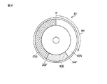
図3は、カラーホイール45の平面構成を例示するもので、平円盤の周面に、無蛍光体部45N、緑色蛍光体反射部45G、及び青色拡散透過部45Bを1つのリングを形成するように配設している。
無蛍光体部45Nは、上記LED42の発光期間に相当する部分であり、蛍光体の塗布や透過板等の配設は行なっていない。緑色蛍光体反射部45Gは、カラーホイール45の平板上に例えば酸化物蛍光体を円弧状に塗布して構成される。青色拡散透過部45Bは、カラーホイール45の平板状に、円弧状半透明の拡散部を埋設して構成される。
FIG. 3 exemplifies a planar configuration of the
The
この図3では、投影する画像フレームの切換タイミングに相当する、カラーホイール45の基準位置を0°とし、カラーホイール45の回転により、半導体レーザ41A〜41Cからの青色光が照射される位置が、図中の矢印MVで示すように無蛍光体部45N、緑色蛍光体反射部45G、及び青色拡散透過部45Bの順で周上を循環的に移動することを表している。
In FIG. 3, the reference position of the
無蛍光体部45Nは、画像フレームに対応した回転位相で0°乃至約144°の位置に144°の中心角をもって配置する。緑色蛍光体反射部45Gは、画像フレームに対応した回転位相で144°乃至295°の位置に151°の中心角をもって配置する。そして、青色拡散透過部45Bを同回転位相で295°乃至360°(0°)の位置に約65°の中心角をもって配置する。
The
次に上記実施形態の動作について説明する。
図4は、CPU32′の制御の下に、投影光処理部31′が光源部17′を駆動する内容を示す図である。
図4(A)は、マイクロミラー素子16に照射される光源光の色を示す。図4(B)はLED42の駆動電流を、図4(C)は半導体レーザ41A〜41C0の駆動電流を示している。
Next, the operation of the above embodiment will be described.
FIG. 4 is a diagram showing the content of the projection
FIG. 4A shows the color of the light source light applied to the
フレーム当初のRフィールドでは、LED42に赤色画像用の駆動電流Irが与えられる。この駆動電流Irは、LED42の発光特性に鑑み、発熱による輝度低下を抑えた電流値が選定される。
In the R field at the beginning of the frame, the
LED42から赤色光が出射される間、半導体レーザ41A〜41Cは駆動されないので、カラーホイール45にはレーザ光が照射されない。このカラーホイール45の中心角で144°に相当する時間中、LED42の出射した赤色光がレンズ群73、ダイクロイックミラー44、レンズ65を介してダイクロイックミラー47で反射され、レンズ66、インテグレータ48、レンズ67、ミラー49、及びレンズ68を介してミラー18で反射されて、マイクロミラー素子16に照射される。このときマイクロミラー素子16では投影画像処理部15の駆動により赤色に対応した画像表示がなされる。
Since the
そのため、マイクロミラー素子16での反射光により赤色の光像が形成され、形成された光像が投影レンズユニット19より投影対象の図示しないスクリーン等に投射される。
Therefore, a red light image is formed by the reflected light from the
続くGフィールドでは、LED42に代えて半導体レーザ41A〜41Cに緑色画像用の駆動電流Igが与えられる。この駆動電流Igは、カラーホイール45の緑色蛍光体反射部45Gを構成する蛍光体、例えば酸化物蛍光体の発光特性に鑑み、飽和が生じて発光効率が低下しない程度に抑えた電流値が選定される。
In the subsequent G field, a green image drive current Ig is applied to the
緑色蛍光体反射部45Gに対して半導体レーザ41A〜41Cからの青色光が照射される、カラーホイール45の中心角で151°に相当する時間中、その励起により生じた緑色光が緑色蛍光体反射部45Gからレンズ群64を介してダイクロイックミラー44で反射され、レンズ65を介してさらにダイクロイックミラー47で反射された後に、レンズ66、インテグレータ48、レンズ67を介してミラー49で反射され、レンズ68を介してミラー18で反射されて、マイクロミラー素子16に照射される。このときマイクロミラー素子16では投影画像処理部15の駆動により緑色に対応した画像表示がなされる。
During the time corresponding to 151 ° at the central angle of the
そのため、マイクロミラー素子16での反射光により緑色の光像が形成され、形成された光像が投影レンズユニット19より投影対象の図示しないスクリーン等に投射される。
Therefore, a green light image is formed by the reflected light from the
そして、続くBフィールドでは、半導体レーザ41A〜41Cに青色画像用の駆動電流Ibが与えられる。この駆動電流Ibは、図4(C)に示す如く、蛍光体による励起を考慮する必要がないために、上記電流Igに比して充分に高い値を設定することができる。
In the subsequent B field, a blue image drive current Ib is applied to the
青色拡散透過部45Bに対して半導体レーザ41A〜41Cからの青色光が照射される、カラーホイール45の中心角で65°に相当する時間中、青色拡散透過部45Bで拡散されながら透過した青色光がレンズ70を介してミラー50で反射され、レンズ71を介してミラー51で反射された後にレンズ72を介してダイクロイックミラー47を透過する。さらにこの青色光は、レンズ66、インテグレータ48、レンズ67を介してミラー49で反射され、レンズ68を介してミラー18で反射されて、マイクロミラー素子16に照射される。このときマイクロミラー素子16では投影画像処理部15の駆動により青に対応した画像表示がなされる。
Blue light that is transmitted through the blue diffused
そのため、マイクロミラー素子16での反射光により青色の光像が形成され、形成された光像が投影レンズユニット19より投影対象の図示しないスクリーン等に投射される。
Therefore, a blue light image is formed by the reflected light from the
すなわち、上述のように赤色光を蛍光体発光からLED42からの発光としたことにより、RGB蛍光体において最も発光効率の悪い赤色蛍光体を使わずに、高い輝度の赤色光を得ることができる。 That is, by changing the red light from the phosphor light emission to the LED light emission as described above, it is possible to obtain red light with high luminance without using the red phosphor having the lowest light emission efficiency in the RGB phosphor.
また、光源光としてLED42を利用するRフィールト゛は、LED42を発熱による発光効率を考慮した電流値で発光させるとともに、その発光期間を調整することで総発光光量が低下しないようにする。
Further, the R field using the
そして、光源光としてレーザ光を励起光として照射する蛍光体からの光を利用するGフィールドは、蛍光体の発光特性に鑑み、飽和が生じない程度に抑えた低電流で発光させるとともに、低電流で発光させる分低下する総発光光量を補うように、その発光期間を充分に長いものとすることで、発光効率の低さを補って充分な明るさの光像を得る。 A G field that uses light from a phosphor that emits laser light as excitation light as light source light emits light at a low current that is suppressed to a level that does not cause saturation, in view of the light emission characteristics of the phosphor, and has a low current. By making the light emission period sufficiently long so as to compensate for the total amount of light emission that is reduced by the amount of light emitted by, a light image with sufficient brightness can be obtained by compensating for the low light emission efficiency.
これに対して、光源光として、蛍光体を使用せず、光源となる発光素子である半導体レーザ41A〜41Cの出射する色の光をそのまま使用するBフィールドでは、期間の短さを補うように大きな電流値で高い輝度の光像を形成するものとする。
On the other hand, in the B field in which the light emitted from the
以上詳記した如く本実施形態によれば、複数の発光素子と蛍光体の有無との組合せにより各色毎に異なる発光効率を考慮して、できる限り明るく且つ色再現性の高い画像を投影することが可能となる。 As described above in detail, according to the present embodiment, an image that is as bright as possible and has high color reproducibility is projected in consideration of different light emission efficiencies for each color depending on the combination of a plurality of light emitting elements and phosphors. Is possible.
なお、上記実施形態では、図3のカラーホイール45の構成、及び図4の光源部の動作タイミングでも示した如く、Gフィールドの後にBフィールドを配置し、且つGフィールドでの半導体レーザ41A〜41Cの駆動電流Igよりも、Bフィールドでの半導体レーザ41A〜41Cの駆動電流Ibの方をより大きく設定した場合について説明した。
In the above embodiment, as shown in the configuration of the
ところで、半導体レーザの駆動方法として異なる駆動電流で時間的に連続して駆動させる際、図5(A)に示すように小さい電流から大きい電流に移行する場合と、図5(B)に示すように大きい電流から小さい電流に移行する場合とでは、半導体レーザに生じる温度変化が、後者の方がより小さいことがわかっている。 Meanwhile, when driving successively in time with different drive current as a driving method of a semiconductor laser, and when moving to large current from the low current as shown in FIG. 5 (A), as shown in FIG. 5 (B) It is known that the temperature change occurring in the semiconductor laser is smaller in the latter when the current is shifted from a large current to a small current.
すなわち、光源の発光素子として半導体レーザを用いる場合には、発光輝度の低下や半導体レーザ41の寿命の点で、上記後者による駆動方法を採った方が望ましい。
以下、そのような半導体レーザ41A〜41Cの素子温度を考慮した場合についても、本実施形態の他の動作例として説明する。
(他の動作例)
図6は、上記カラーホイール45に代わるカラーホイール45′の平面構成を例示するもので、平円盤の周面に、無蛍光体部45N、青色拡散透過部45B、及び緑色蛍光体反射部45Gを1つのリングを形成するように配設している。
この図6では、投影する画像フレームの切換タイミングに相当する、カラーホイール45′の基準位置を0°とし、カラーホイール45′の回転により、半導体レーザ41A〜41Cからの青色光が照射される位置が、図中の矢印MVで示すように無蛍光体部45N、青色拡散透過部45B、及び緑色蛍光体反射部45Gの順で周上を循環的に移動することを表している。
In other words, when a semiconductor laser is used as the light emitting element of the light source, it is desirable to adopt the latter driving method from the viewpoint of a decrease in emission luminance and the life of the
Hereinafter, a case where such element temperatures of the
(Other operation examples)
FIG. 6 exemplifies a planar configuration of a
In FIG. 6, the reference position of the
無蛍光体部45Nは、画像フレームに対応した回転位相で0°乃至約144°の位置に144°の中心角をもって配置する。青色拡散透過部45Bは、画像フレームに対応した回転位相で144°乃至209°の位置に65°の中心角をもって配置する。そして、緑色蛍光体反射部45Gを同回転位相で209°乃至360°(0°)の位置に約151°の中心角をもって配置する。
The
次に上記実施形態の動作について説明する。
図7は、CPU32′の制御の下に、投影光処理部31′が光源部17′を駆動する内容を示す図である。
図7(A)は、マイクロミラー素子16に照射される光源光の色を示す。図7(B)はLED42の駆動電流を、図7(C)は半導体レーザ41A〜41Cの駆動電流を示している。
Next, the operation of the above embodiment will be described.
FIG. 7 is a diagram showing the content of the projection
FIG. 7A shows the color of the light source light applied to the
フレーム当初のRフィールドでは、LED42に赤色画像用の駆動電流Irが与えられる。この駆動電流Irは、LED42の発光特性に鑑み、発熱による輝度低下を抑えた電流値が選定される。
In the R field at the beginning of the frame, the
LED42から赤色光が出射される間、半導体レーザ41A〜41Cは駆動されないので、カラーホイール45にはレーザ光が照射されない。このカラーホイール45の中心角で144°に相当する時間中、LED42の出射した赤色光がレンズ群73、ダイクロイックミラー44、レンズ65を介してダイクロイックミラー47で反射され、レンズ66、インテグレータ48、レンズ67、ミラー49、及びレンズ68を介してミラー18で反射されて、マイクロミラー素子16に照射される。このときマイクロミラー素子16では投影画像処理部15の駆動により赤色に対応した画像表示がなされる。
Since the
そのため、マイクロミラー素子16での反射光により赤色の光像が形成され、形成された光像が投影レンズユニット19より投影対象の図示しないスクリーン等に投射される。
Therefore, a red light image is formed by the reflected light from the
続くBフィールドでは、LED42に代えて半導体レーザ41A〜41Cに青色画像用の駆動電流Ibが与えられる。この駆動電流Ibは、図7(C)に示す如く、蛍光体による励起を考慮する必要がないために、次のGフィールドで用いる電流Igに比して充分に高い値を設定することができる。
In the subsequent B field, a blue image drive current Ib is applied to the
青色拡散透過部45Bに対して半導体レーザ41A〜41Cからの青色光が照射される、カラーホイール45の中心角で65°に相当する時間中、青色拡散透過部45Bで拡散されながら透過した青色光がレンズ70を介してミラー50で反射され、レンズ71を介してミラー51で反射された後にレンズ72を介してダイクロイックミラー47を透過する。さらにこの青色光は、レンズ66、インテグレータ48、レンズ67を介してミラー49で反射され、レンズ68を介してミラー18で反射されて、マイクロミラー素子16に照射される。このときマイクロミラー素子16では投影画像処理部15の駆動により青に対応した画像表示がなされる。
Blue light that is transmitted through the blue diffused
そのため、マイクロミラー素子16での反射光により青色の光像が形成され、形成された光像が投影レンズユニット19より投影対象の図示しないスクリーン等に投射される。
Therefore, a blue light image is formed by the reflected light from the
そして、次のGフィールドでは、半導体レーザ41A〜41Cに上記電流Ibより低い緑色画像用の駆動電流Igが与えられる。この駆動電流Igは、カラーホイール45の緑色蛍光体反射部45Gを構成する蛍光体、例えば酸化物蛍光体の発光特性に鑑みた電流値が選定される。
In the next G field, the
緑色蛍光体反射部45Gに対して半導体レーザ41A〜41Cからの青色光が照射される、カラーホイール45の中心角で151°に相当する時間中、その励起により生じた緑色光が緑色蛍光体反射部45Gからレンズ群64を介してダイクロイックミラー44で反射され、レンズ65を介してさらにダイクロイックミラー47で反射された後に、レンズ66、インテグレータ48、レンズ67を介してミラー49で反射され、レンズ68を介してミラー18で反射されて、マイクロミラー素子16に照射される。このときマイクロミラー素子16では投影画像処理部15の駆動により緑色に対応した画像表示がなされる。
During the time corresponding to 151 ° at the central angle of the
そのため、マイクロミラー素子16での反射光により緑色の光像が形成され、形成された光像が投影レンズユニット19より投影対象の図示しないスクリーン等に投射される。
Therefore, a green light image is formed by the reflected light from the
すなわち、光源光としてLED42を利用するRフィールド、レーザ光を照射する蛍光体からの励起光を利用するGフィールドの期間を充分に長いものとすることで、総発光光量の低さを補って充分な明るさの光像を得る。
That is, by sufficiently lengthening the period of the R field using the
これに対して、光源光として、蛍光体を使用せず、光源となる発光素子である半導体レーザ41A〜41Cの出射する色の光をそのまま使用するBフィールドでは、期間の短さを補うように大きな電流値で高い輝度の光像を形成するものとする。
On the other hand, in the B field in which the light emitted from the
加えて上記実施形態では、同じく半導体レーザ41A〜41Cを時間的に連続して駆動するBフィールドとGフィールドとで、上述した如く、より大きい電流値での駆動となるBフィールドをGフィールドより先に配置するものとした。
In addition, in the above-described embodiment, the B field and the G field, which are similarly driven in time with the
これにより、上記図5でも示した如く、半導体レーザ41A〜41Cでの温度上昇をより低く抑えることができ、半導体レーザ41A〜41Cでの発光輝度の低下を小さくすると共に、半導体レーザ41A〜41Cの長寿命確認も寄与することができる。
As a result, as shown in FIG. 5 above, the temperature rise in the
なお、上記第1及び第2の実施形態はいずれも、半導体レーザ20A〜20C(41A〜41C)で青色のレーザ光を発振してカラーホイール24(45,45′)により青色光及び緑色光を発生させる一方で、LED21(42)で赤色光を発生するものとして説明したが、本発明はこれに限らず、1つの光源で発生しうる原色光の輝度バランスが実用に適さない場合に、他の光源を用いてそれを補償するような、複数種類の光源を用いる光源部、及びそのような光源部を用いる投影装置であれば同様に適用可能である。 In both the first and second embodiments, the semiconductor lasers 20A to 20C (41A to 41C) oscillate blue laser light and the color wheel 24 (45, 45 ') emits blue light and green light. However, the present invention is not limited to this, and the present invention is not limited to this, and the other is used when the luminance balance of primary color light that can be generated by one light source is not suitable for practical use. The present invention can be similarly applied to a light source unit using a plurality of types of light sources and a projection apparatus using such a light source unit.
また、上記各実施形態は共に本発明をDLP(登録商標)方式のデータプロジェクタ装置に適用した場合について説明したものであるが、例えば透過型のモノクロ液晶パネルを用いて光像を形成する液晶プロジェクタ等にも同様に本発明を適用することができる。 In each of the embodiments described above, the present invention is applied to a DLP (registered trademark) type data projector apparatus. For example, a liquid crystal projector that forms a light image using a transmissive monochrome liquid crystal panel. The present invention can be similarly applied to the above.
その他、本発明は上述した実施形態に限定されるものではなく、実施段階ではその要旨を逸脱しない範囲で種々に変形することが可能である。また、上述した実施形態で実行される機能は可能な限り適宜組み合わせて実施しても良い。上述した実施形態には種々の段階が含まれており、開示される複数の構成要件による適宜の組み合せにより種々の発明が抽出され得る。例えば、実施形態に示される全構成要件からいくつかの構成要件が削除されても、効果が得られるのであれば、この構成要件が削除された構成が発明として抽出され得る。 In addition, the present invention is not limited to the above-described embodiments, and various modifications can be made without departing from the scope of the invention in the implementation stage. Further, the functions executed in the above-described embodiments may be combined as appropriate as possible. The above-described embodiment includes various stages, and various inventions can be extracted by an appropriate combination of a plurality of disclosed constituent elements. For example, even if some constituent requirements are deleted from all the constituent requirements shown in the embodiment, if the effect is obtained, a configuration from which the constituent requirements are deleted can be extracted as an invention.
10′…データプロジェクタ装置、11…入出力コネクタ部、12…入出力インタフェース(I/F)、13…画像変換部(スケーラ)、14…ビデオRAM、15…投影画像処理部、16…マイクロミラー素子(SLM)、17′…光源部、18…ミラー、19…投影レンズユニット、20…(B発光)半導体レーザ、21…ダイクロイックミラー、22…レンズ、23…レンズ群、24…カラーホイール、24B…青色用拡散部、24G…緑色蛍光体反射部、24R…赤色蛍光体反射部、25…モータ、26…レンズ、27…インテグレータ、28…レンズ、31′…投影光処理部、32,32′…CPU、33…メインメモリ、34…プログラムメモリ、35…操作部、36…音声処理部、37…スピーカ部、41…半導体レーザ、41A〜41C…半導体レーザ、42…LED、43A〜43C…ミラー、44…ダイクロイックミラー、45,45′…カラーホイール、45B…青色用拡散部、45N…無蛍光体部、45G…緑色蛍光体反射部、46…モータ、47…ダイクロイックミラー、48…インテグレータ、49〜51…ミラー、61A〜61C,62,63…レンズ、64…レンズ群、65〜72…レンズ、73…レンズ群、SB…システムバス。
DESCRIPTION OF SYMBOLS 10 ' ... Data projector apparatus, 11 ... Input / output connector part, 12 ... Input / output interface (I / F), 13 ... Image conversion part (scaler), 14 ... Video RAM, 15 ... Projection image processing part, 16 ... Micromirror Element (SLM), 17 ' ... light source, 18 ... mirror, 19 ... projection lens unit, 20 ... (B emission) semiconductor laser, 21 ... dichroic mirror, 22 ... lens, 23 ... lens group, 24 ... color wheel, 24B ... Blue diffuser, 24G ... Green phosphor reflector, 24R ... Red phosphor reflector, 25 ... Motor, 26 ... Lens, 27 ... Integrator, 28 ... Lens, 31 ' ... Projection light processor, 32, 32' ... CPU, 33 ... Main memory, 34 ... Program memory, 35 ... Operation part, 36 ... Audio processing part, 37 ... Speaker part, 41 ...
Claims (10)
上記第1の光源素子の発光を用い、上記第1の波長帯域の光をそのまま使用する第1の領域と、上記第1の波長帯域の光を励起光として上記第1の波長帯域とは異なる波長帯域の光を発生する第2の領域と、を含み、時分割で異なる複数色の光源光を発生する光源光発生手段と、
上記複数色の光源光中、上記第1の領域では、光源光の発生時間を上記第2の領域で発生する光の発生時間より短く設定するととともに、
当該発生時間を短く設定した上記第1の波長帯域の光の光源光発生時の上記第1の光源素子の駆動電力を、上記第2の領域で発生する光の光源光発生時の上記第1の光源素子の駆動電力より大きく設定し、
上記光源光発生手段で発生する上記複数色の光源光が循環的に発生するように上記第1の光源素子と上記光源光発生手段の駆動タイミングを制御する光源制御手段と、
を具備したことを特徴とする光源装置。 A first light source element that emits light in a first wavelength band;
The first region using the light of the first light source element and using the light of the first wavelength band as it is is different from the first wavelength band using the light of the first wavelength band as excitation light. A second region that generates light in a wavelength band, and a light source light generating unit that generates light sources of different colors in a time division manner,
Among the light sources of the plurality of colors, in the first area, the generation time of the light source light is set shorter than the generation time of the light generated in the second area,
The driving power of the first light source element when the light source light of the light of the first wavelength band in which the generation time is set short is used as the first power when the light source light of the light generated in the second region is generated. Set larger than the driving power of the light source element
Light source control means for controlling the drive timing of the first light source element and the light source light generating means so that the light sources of the plurality of colors generated by the light source light generating means are cyclically generated;
A light source device comprising:
上記光源制御手段は、
上記複数色の光源光中、上記第1の領域では、光源光の発生時間を上記第2の波長帯域の光の発生時間より短く設定するととともに、
当該発生時間を短く設定した上記第1の波長帯域の光の光源光発生時の上記第1の光源素子の駆動電力を、上記第2の波長帯域の光の光源光発生時の上記第1の光源素子の駆動電力より大きく設定し、
上記光源光発生手段で発生する複数色の光源光が循環的に発生するように上記第1の光源素子と上記光源光発生手段の駆動タイミングを制御することを特徴とする請求項1又は2に記載の光源装置。 A second light source element that emits light in a second wavelength band different from the light generated in the first wavelength band and the second region of the light source light generating means;
The light source control means includes
Among the light sources of the plurality of colors, in the first region, the generation time of the light source light is set shorter than the generation time of the light in the second wavelength band,
The driving power of the first light source element when the light source light of the light of the first wavelength band in which the generation time is set short is set as the driving power of the first light source light of the light of the second wavelength band. Set larger than the driving power of the light source element,
3. The drive timing of the first light source element and the light source light generating means is controlled so that a plurality of color light source lights generated by the light source light generating means are generated cyclically. The light source device described.
画像信号を入力する入力手段と、
上記光源制御手段での制御に基づいて出射される光源光を用い、上記入力手段で入力する画像信号に対応したカラーの光像を形成して投影する投影手段と、
を具備したことを特徴とする投影装置。 A light source device according to any one of claims 1 to 5 ,
An input means for inputting an image signal;
Projecting means for forming and projecting a color light image corresponding to an image signal input by the input means, using light source light emitted based on control by the light source control means,
A projection apparatus comprising:
上記光源素子の発光を用い、上記第1の波長帯域の光をそのまま使用する第1の領域と、上記第1の波長帯域の光を励起光として上記第1の波長帯域とは異なる波長帯域の光を発生する第2の領域と、を含み、時分割で異なる複数色の光源光を発生する光源光発生部、
画像信号を入力する入力部、
及び光源光を用い、上記入力部で入力する画像信号に対応したカラーの光像を形成して投影する投影部、
を備えた投影装置での投影方法であって、
上記複数色の光源光中、上記第1の領域では、光源光の発生時間を上記第2の領域で発生する光の発生時間より短く設定するととともに、
当該発生時間を短く設定した上記第1の波長帯域の光の光源光発生時の上記光源素子の駆動電力を、上記第2の領域で発生する光の光源光発生時の上記光源素子の駆動電力より大きく設定し、
上記光源光発生部で発生する複数色の光源光が循環的に発生するように上記光源素子と上記光源光発生部の駆動タイミングを制御する光源制御工程
を有したことを特徴とする投影方法。 A light source element that emits light in a first wavelength band;
A first region that uses light of the first wavelength band as it is using light emission of the light source element, and a wavelength band different from the first wavelength band using the light of the first wavelength band as excitation light. A light source light generator that generates light sources of a plurality of different colors in a time-sharing manner,
An input unit for inputting image signals;
And a projection unit that forms and projects a color light image corresponding to the image signal input by the input unit using the light source light,
A projection method with a projection apparatus comprising:
Among the light sources of the plurality of colors, in the first area, the generation time of the light source light is set shorter than the generation time of the light generated in the second area,
The driving power of the light source element when the light source light of the light of the first wavelength band in which the generation time is set short is used, and the driving power of the light source element when the light source light of the light generated in the second region is generated. Set larger,
Projection method characterized by having a light source control step of controlling the driving timing of the light source element and the light source light generator as a plurality of colors of light sources light generated by the light source light generation section to generate cyclically.
上記第1の光源素子の発光を用い、上記第1の波長帯域の光をそのまま使用する第1の領域と、上記第1の波長帯域の光を励起光として上記第1の波長帯域とは異なる波長帯域の光を発生する第2の領域と、を含み、時分割で異なる複数色の光源光を発生する光源光発生部、
上記第1の波長帯域とは異なる第2の波長帯域で発光する第2の光源素子、
画像信号を入力する入力部、
及び光源光を用い、上記入力部で入力する画像信号に対応したカラーの光像を形成して投影する投影部、
を備えた投影装置での投影方法であって、
上記複数色の光源光中、上記第1の領域では、光源光の発生時間を上記第2の領域で発生する光の発生時間より短く設定するととともに、
当該発生時間を短く設定した上記第1の波長帯域の光の光源光発生時の上記第1の光源素子の駆動電力を、上記第2の領域で発生する光の光源光発生時の上記第1の光源素子の駆動電力より大きく設定し、
上記光源光発生部で発生する複数色の光源光が循環的に発生するように上記第1及び上記第2の光源素子と上記光源光発生部の駆動タイミングを制御する光源制御工程
を有したことを特徴とする投影方法。 A first light source element that emits light in a first wavelength band;
The first region using the light of the first light source element and using the light of the first wavelength band as it is is different from the first wavelength band using the light of the first wavelength band as excitation light. A second region that generates light in a wavelength band, and a light source light generation unit that generates light sources of different colors in a time division manner,
A second light source element that emits light in a second wavelength band different from the first wavelength band;
An input unit for inputting image signals;
And a projection unit that forms and projects a color light image corresponding to the image signal input by the input unit using the light source light,
A projection method with a projection apparatus comprising:
During the plurality of colors of light sources light, in the first region, the time of occurrence of the source light with when shorter than the generation time of the light generated by the second realm,
The driving power of the first light source device at the time of the light source light generation of the light of the first wavelength band shorter the generation time, the first of the time-source light generation of the light generated in the second realm Set larger than the driving power of one light source element,
That includes a light source control step of a plurality of colors of light sources light generated by the light source light generation section controls the first and driving timing of the second light source element and the light-source light generation section to generate cyclically A projection method characterized by
Priority Applications (4)
| Application Number | Priority Date | Filing Date | Title |
|---|---|---|---|
| JP2009223333A JP5796272B2 (en) | 2009-09-28 | 2009-09-28 | Light source device, projection device, and projection method |
| US12/888,659 US8403493B2 (en) | 2009-09-28 | 2010-09-23 | Projection apparatus and projection method for controlling emission of plural color light sources having different luminous efficiencies |
| CN2010102937307A CN102033397B (en) | 2009-09-28 | 2010-09-26 | Light source unit, projection apparatus, and projection method |
| TW099132518A TWI439789B (en) | 2009-09-28 | 2010-09-27 | Light source unit, projection apparatus, and projection method |
Applications Claiming Priority (1)
| Application Number | Priority Date | Filing Date | Title |
|---|---|---|---|
| JP2009223333A JP5796272B2 (en) | 2009-09-28 | 2009-09-28 | Light source device, projection device, and projection method |
Publications (3)
| Publication Number | Publication Date |
|---|---|
| JP2011070127A JP2011070127A (en) | 2011-04-07 |
| JP2011070127A5 JP2011070127A5 (en) | 2012-11-08 |
| JP5796272B2 true JP5796272B2 (en) | 2015-10-21 |
Family
ID=43780005
Family Applications (1)
| Application Number | Title | Priority Date | Filing Date |
|---|---|---|---|
| JP2009223333A Active JP5796272B2 (en) | 2009-09-28 | 2009-09-28 | Light source device, projection device, and projection method |
Country Status (4)
| Country | Link |
|---|---|
| US (1) | US8403493B2 (en) |
| JP (1) | JP5796272B2 (en) |
| CN (1) | CN102033397B (en) |
| TW (1) | TWI439789B (en) |
Families Citing this family (48)
| Publication number | Priority date | Publication date | Assignee | Title |
|---|---|---|---|---|
| JP4924677B2 (en) | 2009-08-21 | 2012-04-25 | カシオ計算機株式会社 | Light source device, projection device, and projection method |
| US8936368B2 (en) * | 2010-01-29 | 2015-01-20 | Nec Display Solutions, Ltd. | Illumination optical system and projector using the same |
| JP4973962B2 (en) * | 2010-03-31 | 2012-07-11 | カシオ計算機株式会社 | Light source device and projector |
| JP5534331B2 (en) * | 2010-07-30 | 2014-06-25 | カシオ計算機株式会社 | Light source unit and projector |
| JP5703631B2 (en) | 2010-08-26 | 2015-04-22 | セイコーエプソン株式会社 | projector |
| US8955985B2 (en) * | 2010-10-19 | 2015-02-17 | Nec Display Solutions, Ltd. | Lighting device and projection-type display device using same |
| US9046750B2 (en) * | 2010-11-17 | 2015-06-02 | Nec Display Solutions, Ltd. | Projector light source apparatus having collimator disposed between excitation light source and phosphor element |
| DE102011003665B4 (en) * | 2011-02-04 | 2019-08-14 | Osram Gmbh | lighting device |
| CN103430093B (en) | 2011-03-18 | 2015-05-20 | Nec显示器解决方案株式会社 | Phosphor-equipped illumination optical system and projector |
| JP5223941B2 (en) * | 2011-03-28 | 2013-06-26 | カシオ計算機株式会社 | Projection device |
| JP5979416B2 (en) * | 2011-04-20 | 2016-08-24 | パナソニックIpマネジメント株式会社 | Light source device and image display device |
| JP2013029831A (en) * | 2011-06-23 | 2013-02-07 | Panasonic Corp | Illumination apparatus and projection type image display apparatus |
| JP5906416B2 (en) * | 2011-06-30 | 2016-04-20 | パナソニックIpマネジメント株式会社 | Illumination device and projection display device |
| JP5987382B2 (en) * | 2011-07-22 | 2016-09-07 | 株式会社リコー | LIGHTING DEVICE, PROJECTION DEVICE, AND METHOD FOR CONTROLLING PROJECTION DEVICE |
| TWI439793B (en) * | 2011-08-03 | 2014-06-01 | Hon Hai Prec Ind Co Ltd | Porjector light source apparatus |
| TWI440956B (en) * | 2011-08-17 | 2014-06-11 | Hon Hai Prec Ind Co Ltd | Porjector light source apparatus |
| CN102955241A (en) * | 2011-08-29 | 2013-03-06 | 鸿富锦精密工业(深圳)有限公司 | Light source device of projector |
| JP2013072888A (en) * | 2011-09-26 | 2013-04-22 | Sanyo Electric Co Ltd | Projection type image displaying apparatus |
| CN103034035A (en) * | 2011-09-30 | 2013-04-10 | 中强光电股份有限公司 | Illuminating system and projecting apparatus |
| JP5862938B2 (en) * | 2011-10-03 | 2016-02-16 | カシオ計算機株式会社 | Light source device and projector |
| JP5494610B2 (en) * | 2011-10-17 | 2014-05-21 | カシオ計算機株式会社 | Projection apparatus, projection control method, and program |
| TW201317701A (en) * | 2011-10-24 | 2013-05-01 | Hon Hai Prec Ind Co Ltd | Optical mechanical of projector |
| CN103076712B (en) * | 2011-10-26 | 2015-05-27 | 深圳市光峰光电技术有限公司 | Projection light source and projection device using same |
| JP6098074B2 (en) * | 2011-10-31 | 2017-03-22 | 株式会社リコー | Projection display device |
| CN103207507B (en) | 2012-01-11 | 2015-07-08 | 中强光电股份有限公司 | Light source module and projector |
| JP2013160894A (en) * | 2012-02-03 | 2013-08-19 | Ricoh Co Ltd | Light source device, and projection display device |
| CN104880897A (en) * | 2012-03-19 | 2015-09-02 | 深圳市光峰光电技术有限公司 | Lighting device and projection device |
| CN103424961A (en) * | 2012-05-23 | 2013-12-04 | 鸿富锦精密工业(深圳)有限公司 | Digital optical processing projector |
| CN103631075B (en) | 2012-08-24 | 2016-08-03 | 扬明光学股份有限公司 | Illuminator, projection arrangement and means of illumination |
| CN104769497B (en) | 2012-11-07 | 2016-09-28 | 松下知识产权经营株式会社 | light source and image projection device |
| JP6305009B2 (en) * | 2013-01-11 | 2018-04-04 | 三菱電機株式会社 | Light source device and projector |
| JP6186752B2 (en) * | 2013-03-01 | 2017-08-30 | カシオ計算機株式会社 | Light source device and projection device |
| JP6205835B2 (en) * | 2013-05-14 | 2017-10-04 | 株式会社リコー | LIGHTING DEVICE, PROJECTION DEVICE PROVIDED WITH THIS LIGHTING DEVICE, AND LIGHTING METHOD |
| JP2015025832A (en) * | 2013-07-24 | 2015-02-05 | カシオ計算機株式会社 | Light source device and projector |
| TWI480585B (en) * | 2013-07-30 | 2015-04-11 | Delta Electronics Inc | Display Illuminating Module |
| JP6286953B2 (en) * | 2013-09-06 | 2018-03-07 | カシオ計算機株式会社 | Light source device and projection device |
| JP6332678B2 (en) * | 2014-05-27 | 2018-05-30 | カシオ計算機株式会社 | Light source device and projection device |
| TWI584043B (en) * | 2014-09-05 | 2017-05-21 | 台達電子工業股份有限公司 | Wavelength-converting device and illumination system using same |
| DE102014221382A1 (en) * | 2014-10-21 | 2016-04-21 | Osram Gmbh | Lighting device with pumping radiation source |
| DE102014222130A1 (en) * | 2014-10-29 | 2016-05-04 | Osram Gmbh | Lighting device with a wavelength conversion arrangement |
| TWI575299B (en) * | 2015-05-08 | 2017-03-21 | 中強光電股份有限公司 | Illumination system and projection apparatus |
| JP6946650B2 (en) * | 2017-02-01 | 2021-10-06 | セイコーエプソン株式会社 | Light source device and projector |
| CN108931880B (en) * | 2017-05-26 | 2023-03-14 | 深圳光峰科技股份有限公司 | Light source system and display device |
| JP6575617B2 (en) * | 2018-01-31 | 2019-09-18 | カシオ計算機株式会社 | Light source device and projection device |
| US20190258148A1 (en) * | 2018-02-21 | 2019-08-22 | Casio Computer Co., Ltd. | Light source device and projector |
| CN108710256B (en) * | 2018-03-30 | 2020-09-08 | 苏州佳世达光电有限公司 | Light splitting module and projection device using same |
| JP6669192B2 (en) * | 2018-04-24 | 2020-03-18 | カシオ計算機株式会社 | Light source device and projection device |
| JP7098483B2 (en) * | 2018-08-31 | 2022-07-11 | キヤノン株式会社 | Light source device and image projection device |
Family Cites Families (14)
| Publication number | Priority date | Publication date | Assignee | Title |
|---|---|---|---|---|
| US5428408A (en) * | 1994-05-26 | 1995-06-27 | Philips Electronics North America Corporation | Color correction system for projection video system utilizing multiple light sources |
| US6520648B2 (en) * | 2001-02-06 | 2003-02-18 | Infocus Corporation | Lamp power pulse modulation in color sequential projection displays |
| JP2003044016A (en) * | 2001-08-02 | 2003-02-14 | Matsushita Electric Ind Co Ltd | Liquid crystal display device and driving method therefor |
| JP4829470B2 (en) * | 2003-05-14 | 2011-12-07 | Necディスプレイソリューションズ株式会社 | Projection display |
| US7070300B2 (en) * | 2004-06-04 | 2006-07-04 | Philips Lumileds Lighting Company, Llc | Remote wavelength conversion in an illumination device |
| JP2006023436A (en) * | 2004-07-07 | 2006-01-26 | Olympus Corp | Illuminating apparatus and projector |
| US7234820B2 (en) * | 2005-04-11 | 2007-06-26 | Philips Lumileds Lighting Company, Llc | Illuminators using reflective optics with recycling and color mixing |
| JP2007156270A (en) * | 2005-12-07 | 2007-06-21 | Sharp Corp | Light source device and projection-type image display device |
| JP2007218956A (en) * | 2006-02-14 | 2007-08-30 | Sharp Corp | Projection type image display apparatus |
| RU2427753C2 (en) * | 2006-06-02 | 2011-08-27 | Конинклейке Филипс Электроникс Н.В. | Coloured and white light-emitting device |
| WO2008015953A1 (en) * | 2006-08-04 | 2008-02-07 | Sharp Kabushiki Kaisha | Image display device |
| JP2008261998A (en) * | 2007-04-11 | 2008-10-30 | Olympus Corp | Light source device and projector |
| WO2009069010A1 (en) * | 2007-11-28 | 2009-06-04 | Koninklijke Philips Electronics N.V. | Illumination system, method and projection device for controlling light emitted during a spoke time period |
| JP4900428B2 (en) * | 2008-09-26 | 2012-03-21 | カシオ計算機株式会社 | Projection apparatus and projection method |
-
2009
- 2009-09-28 JP JP2009223333A patent/JP5796272B2/en active Active
-
2010
- 2010-09-23 US US12/888,659 patent/US8403493B2/en active Active
- 2010-09-26 CN CN2010102937307A patent/CN102033397B/en active Active
- 2010-09-27 TW TW099132518A patent/TWI439789B/en active
Also Published As
| Publication number | Publication date |
|---|---|
| US20110075103A1 (en) | 2011-03-31 |
| CN102033397A (en) | 2011-04-27 |
| CN102033397B (en) | 2013-07-10 |
| TW201124791A (en) | 2011-07-16 |
| US8403493B2 (en) | 2013-03-26 |
| TWI439789B (en) | 2014-06-01 |
| JP2011070127A (en) | 2011-04-07 |
Similar Documents
| Publication | Publication Date | Title |
|---|---|---|
| JP5796272B2 (en) | Light source device, projection device, and projection method | |
| JP4924677B2 (en) | Light source device, projection device, and projection method | |
| JP5412996B2 (en) | Light source device, projection device, and projection method | |
| JP5585475B2 (en) | Projection device | |
| JP5625287B2 (en) | Light source device, projection device, projection method and program | |
| JP5418839B2 (en) | Light source unit and projector | |
| JP2011075919A (en) | Light source device, projection apparatus and projection method | |
| JP5625675B2 (en) | Projection apparatus, projection method, and program | |
| JP2012128438A (en) | Light source device, projection device, and projection method | |
| JP5428710B2 (en) | Light source device, projection device, and projection method | |
| JP5930001B2 (en) | Projection device | |
| JP6820703B2 (en) | Light source device and projection device | |
| JP5915317B2 (en) | Light source device, projector device, and light source driving method | |
| JP5929995B2 (en) | Rotating body and projection device | |
| JP5668286B2 (en) | Projection apparatus, projection method, and program | |
| JP5652500B2 (en) | Light source device, projection device, projection method and program | |
| JP5637405B2 (en) | Rotating body, projection apparatus, projection method and program | |
| KR20110046340A (en) | Light source unit and projector |
Legal Events
| Date | Code | Title | Description |
|---|---|---|---|
| A521 | Written amendment |
Free format text: JAPANESE INTERMEDIATE CODE: A523 Effective date: 20120924 |
|
| A621 | Written request for application examination |
Free format text: JAPANESE INTERMEDIATE CODE: A621 Effective date: 20120924 |
|
| A977 | Report on retrieval |
Free format text: JAPANESE INTERMEDIATE CODE: A971007 Effective date: 20130624 |
|
| A131 | Notification of reasons for refusal |
Free format text: JAPANESE INTERMEDIATE CODE: A131 Effective date: 20130709 |
|
| A521 | Written amendment |
Free format text: JAPANESE INTERMEDIATE CODE: A523 Effective date: 20130909 |
|
| A131 | Notification of reasons for refusal |
Free format text: JAPANESE INTERMEDIATE CODE: A131 Effective date: 20140304 |
|
| A521 | Written amendment |
Free format text: JAPANESE INTERMEDIATE CODE: A523 Effective date: 20140422 |
|
| A02 | Decision of refusal |
Free format text: JAPANESE INTERMEDIATE CODE: A02 Effective date: 20141125 |
|
| A521 | Written amendment |
Free format text: JAPANESE INTERMEDIATE CODE: A523 Effective date: 20150220 |
|
| A911 | Transfer to examiner for re-examination before appeal (zenchi) |
Free format text: JAPANESE INTERMEDIATE CODE: A911 Effective date: 20150227 |
|
| A131 | Notification of reasons for refusal |
Free format text: JAPANESE INTERMEDIATE CODE: A131 Effective date: 20150421 |
|
| A521 | Written amendment |
Free format text: JAPANESE INTERMEDIATE CODE: A523 Effective date: 20150611 |
|
| TRDD | Decision of grant or rejection written | ||
| A01 | Written decision to grant a patent or to grant a registration (utility model) |
Free format text: JAPANESE INTERMEDIATE CODE: A01 Effective date: 20150721 |
|
| A61 | First payment of annual fees (during grant procedure) |
Free format text: JAPANESE INTERMEDIATE CODE: A61 Effective date: 20150803 |
|
| R150 | Certificate of patent or registration of utility model |
Ref document number: 5796272 Country of ref document: JP Free format text: JAPANESE INTERMEDIATE CODE: R150 |