JP5625287B2 - Light source device, projection device, projection method and program - Google Patents
Light source device, projection device, projection method and program Download PDFInfo
- Publication number
- JP5625287B2 JP5625287B2 JP2009192595A JP2009192595A JP5625287B2 JP 5625287 B2 JP5625287 B2 JP 5625287B2 JP 2009192595 A JP2009192595 A JP 2009192595A JP 2009192595 A JP2009192595 A JP 2009192595A JP 5625287 B2 JP5625287 B2 JP 5625287B2
- Authority
- JP
- Japan
- Prior art keywords
- light
- light source
- wavelength band
- color wheel
- generated
- Prior art date
- Legal status (The legal status is an assumption and is not a legal conclusion. Google has not performed a legal analysis and makes no representation as to the accuracy of the status listed.)
- Active
Links
Images


Classifications
-
- G—PHYSICS
- G03—PHOTOGRAPHY; CINEMATOGRAPHY; ANALOGOUS TECHNIQUES USING WAVES OTHER THAN OPTICAL WAVES; ELECTROGRAPHY; HOLOGRAPHY
- G03B—APPARATUS OR ARRANGEMENTS FOR TAKING PHOTOGRAPHS OR FOR PROJECTING OR VIEWING THEM; APPARATUS OR ARRANGEMENTS EMPLOYING ANALOGOUS TECHNIQUES USING WAVES OTHER THAN OPTICAL WAVES; ACCESSORIES THEREFOR
- G03B21/00—Projectors or projection-type viewers; Accessories therefor
- G03B21/14—Details
- G03B21/20—Lamp housings
- G03B21/2006—Lamp housings characterised by the light source
- G03B21/2013—Plural light sources
-
- G—PHYSICS
- G03—PHOTOGRAPHY; CINEMATOGRAPHY; ANALOGOUS TECHNIQUES USING WAVES OTHER THAN OPTICAL WAVES; ELECTROGRAPHY; HOLOGRAPHY
- G03B—APPARATUS OR ARRANGEMENTS FOR TAKING PHOTOGRAPHS OR FOR PROJECTING OR VIEWING THEM; APPARATUS OR ARRANGEMENTS EMPLOYING ANALOGOUS TECHNIQUES USING WAVES OTHER THAN OPTICAL WAVES; ACCESSORIES THEREFOR
- G03B21/00—Projectors or projection-type viewers; Accessories therefor
- G03B21/14—Details
- G03B21/20—Lamp housings
- G03B21/2006—Lamp housings characterised by the light source
- G03B21/2033—LED or laser light sources
- G03B21/204—LED or laser light sources using secondary light emission, e.g. luminescence or fluorescence
-
- G—PHYSICS
- G03—PHOTOGRAPHY; CINEMATOGRAPHY; ANALOGOUS TECHNIQUES USING WAVES OTHER THAN OPTICAL WAVES; ELECTROGRAPHY; HOLOGRAPHY
- G03B—APPARATUS OR ARRANGEMENTS FOR TAKING PHOTOGRAPHS OR FOR PROJECTING OR VIEWING THEM; APPARATUS OR ARRANGEMENTS EMPLOYING ANALOGOUS TECHNIQUES USING WAVES OTHER THAN OPTICAL WAVES; ACCESSORIES THEREFOR
- G03B21/00—Projectors or projection-type viewers; Accessories therefor
- G03B21/14—Details
- G03B21/20—Lamp housings
- G03B21/2053—Intensity control of illuminating light
-
- G—PHYSICS
- G03—PHOTOGRAPHY; CINEMATOGRAPHY; ANALOGOUS TECHNIQUES USING WAVES OTHER THAN OPTICAL WAVES; ELECTROGRAPHY; HOLOGRAPHY
- G03B—APPARATUS OR ARRANGEMENTS FOR TAKING PHOTOGRAPHS OR FOR PROJECTING OR VIEWING THEM; APPARATUS OR ARRANGEMENTS EMPLOYING ANALOGOUS TECHNIQUES USING WAVES OTHER THAN OPTICAL WAVES; ACCESSORIES THEREFOR
- G03B33/00—Colour photography, other than mere exposure or projection of a colour film
- G03B33/10—Simultaneous recording or projection
- G03B33/12—Simultaneous recording or projection using beam-splitting or beam-combining systems, e.g. dichroic mirrors
-
- G—PHYSICS
- G09—EDUCATION; CRYPTOGRAPHY; DISPLAY; ADVERTISING; SEALS
- G09G—ARRANGEMENTS OR CIRCUITS FOR CONTROL OF INDICATING DEVICES USING STATIC MEANS TO PRESENT VARIABLE INFORMATION
- G09G3/00—Control arrangements or circuits, of interest only in connection with visual indicators other than cathode-ray tubes
- G09G3/001—Control arrangements or circuits, of interest only in connection with visual indicators other than cathode-ray tubes using specific devices not provided for in groups G09G3/02 - G09G3/36, e.g. using an intermediate record carrier such as a film slide; Projection systems; Display of non-alphanumerical information, solely or in combination with alphanumerical information, e.g. digital display on projected diapositive as background
-
- G—PHYSICS
- G09—EDUCATION; CRYPTOGRAPHY; DISPLAY; ADVERTISING; SEALS
- G09G—ARRANGEMENTS OR CIRCUITS FOR CONTROL OF INDICATING DEVICES USING STATIC MEANS TO PRESENT VARIABLE INFORMATION
- G09G3/00—Control arrangements or circuits, of interest only in connection with visual indicators other than cathode-ray tubes
- G09G3/20—Control arrangements or circuits, of interest only in connection with visual indicators other than cathode-ray tubes for presentation of an assembly of a number of characters, e.g. a page, by composing the assembly by combination of individual elements arranged in a matrix no fixed position being assigned to or needed to be assigned to the individual characters or partial characters
- G09G3/34—Control arrangements or circuits, of interest only in connection with visual indicators other than cathode-ray tubes for presentation of an assembly of a number of characters, e.g. a page, by composing the assembly by combination of individual elements arranged in a matrix no fixed position being assigned to or needed to be assigned to the individual characters or partial characters by control of light from an independent source
- G09G3/3406—Control of illumination source
- G09G3/3413—Details of control of colour illumination sources
-
- H—ELECTRICITY
- H04—ELECTRIC COMMUNICATION TECHNIQUE
- H04N—PICTORIAL COMMUNICATION, e.g. TELEVISION
- H04N5/00—Details of television systems
- H04N5/14—Picture signal circuitry for video frequency region
- H04N5/144—Movement detection
- H04N5/145—Movement estimation
-
- H—ELECTRICITY
- H04—ELECTRIC COMMUNICATION TECHNIQUE
- H04N—PICTORIAL COMMUNICATION, e.g. TELEVISION
- H04N9/00—Details of colour television systems
- H04N9/12—Picture reproducers
- H04N9/31—Projection devices for colour picture display, e.g. using electronic spatial light modulators [ESLM]
- H04N9/3141—Constructional details thereof
- H04N9/315—Modulator illumination systems
- H04N9/3155—Modulator illumination systems for controlling the light source
-
- H—ELECTRICITY
- H04—ELECTRIC COMMUNICATION TECHNIQUE
- H04N—PICTORIAL COMMUNICATION, e.g. TELEVISION
- H04N9/00—Details of colour television systems
- H04N9/12—Picture reproducers
- H04N9/31—Projection devices for colour picture display, e.g. using electronic spatial light modulators [ESLM]
- H04N9/3141—Constructional details thereof
- H04N9/315—Modulator illumination systems
- H04N9/3158—Modulator illumination systems for controlling the spectrum
-
- G—PHYSICS
- G09—EDUCATION; CRYPTOGRAPHY; DISPLAY; ADVERTISING; SEALS
- G09G—ARRANGEMENTS OR CIRCUITS FOR CONTROL OF INDICATING DEVICES USING STATIC MEANS TO PRESENT VARIABLE INFORMATION
- G09G2310/00—Command of the display device
- G09G2310/02—Addressing, scanning or driving the display screen or processing steps related thereto
- G09G2310/0235—Field-sequential colour display
-
- G—PHYSICS
- G09—EDUCATION; CRYPTOGRAPHY; DISPLAY; ADVERTISING; SEALS
- G09G—ARRANGEMENTS OR CIRCUITS FOR CONTROL OF INDICATING DEVICES USING STATIC MEANS TO PRESENT VARIABLE INFORMATION
- G09G2320/00—Control of display operating conditions
- G09G2320/04—Maintaining the quality of display appearance
- G09G2320/043—Preventing or counteracting the effects of ageing
- G09G2320/048—Preventing or counteracting the effects of ageing using evaluation of the usage time
-
- G—PHYSICS
- G09—EDUCATION; CRYPTOGRAPHY; DISPLAY; ADVERTISING; SEALS
- G09G—ARRANGEMENTS OR CIRCUITS FOR CONTROL OF INDICATING DEVICES USING STATIC MEANS TO PRESENT VARIABLE INFORMATION
- G09G2320/00—Control of display operating conditions
- G09G2320/06—Adjustment of display parameters
- G09G2320/0606—Manual adjustment
-
- G—PHYSICS
- G09—EDUCATION; CRYPTOGRAPHY; DISPLAY; ADVERTISING; SEALS
- G09G—ARRANGEMENTS OR CIRCUITS FOR CONTROL OF INDICATING DEVICES USING STATIC MEANS TO PRESENT VARIABLE INFORMATION
- G09G2320/00—Control of display operating conditions
- G09G2320/06—Adjustment of display parameters
- G09G2320/0666—Adjustment of display parameters for control of colour parameters, e.g. colour temperature
-
- G—PHYSICS
- G09—EDUCATION; CRYPTOGRAPHY; DISPLAY; ADVERTISING; SEALS
- G09G—ARRANGEMENTS OR CIRCUITS FOR CONTROL OF INDICATING DEVICES USING STATIC MEANS TO PRESENT VARIABLE INFORMATION
- G09G2320/00—Control of display operating conditions
- G09G2320/06—Adjustment of display parameters
- G09G2320/0693—Calibration of display systems
-
- G—PHYSICS
- G09—EDUCATION; CRYPTOGRAPHY; DISPLAY; ADVERTISING; SEALS
- G09G—ARRANGEMENTS OR CIRCUITS FOR CONTROL OF INDICATING DEVICES USING STATIC MEANS TO PRESENT VARIABLE INFORMATION
- G09G2320/00—Control of display operating conditions
- G09G2320/08—Arrangements within a display terminal for setting, manually or automatically, display parameters of the display terminal
-
- G—PHYSICS
- G09—EDUCATION; CRYPTOGRAPHY; DISPLAY; ADVERTISING; SEALS
- G09G—ARRANGEMENTS OR CIRCUITS FOR CONTROL OF INDICATING DEVICES USING STATIC MEANS TO PRESENT VARIABLE INFORMATION
- G09G2330/00—Aspects of power supply; Aspects of display protection and defect management
- G09G2330/02—Details of power systems and of start or stop of display operation
- G09G2330/027—Arrangements or methods related to powering off a display
-
- G—PHYSICS
- G09—EDUCATION; CRYPTOGRAPHY; DISPLAY; ADVERTISING; SEALS
- G09G—ARRANGEMENTS OR CIRCUITS FOR CONTROL OF INDICATING DEVICES USING STATIC MEANS TO PRESENT VARIABLE INFORMATION
- G09G2340/00—Aspects of display data processing
- G09G2340/14—Solving problems related to the presentation of information to be displayed
-
- G—PHYSICS
- G09—EDUCATION; CRYPTOGRAPHY; DISPLAY; ADVERTISING; SEALS
- G09G—ARRANGEMENTS OR CIRCUITS FOR CONTROL OF INDICATING DEVICES USING STATIC MEANS TO PRESENT VARIABLE INFORMATION
- G09G2360/00—Aspects of the architecture of display systems
- G09G2360/14—Detecting light within display terminals, e.g. using a single or a plurality of photosensors
- G09G2360/145—Detecting light within display terminals, e.g. using a single or a plurality of photosensors the light originating from the display screen
-
- G—PHYSICS
- G09—EDUCATION; CRYPTOGRAPHY; DISPLAY; ADVERTISING; SEALS
- G09G—ARRANGEMENTS OR CIRCUITS FOR CONTROL OF INDICATING DEVICES USING STATIC MEANS TO PRESENT VARIABLE INFORMATION
- G09G3/00—Control arrangements or circuits, of interest only in connection with visual indicators other than cathode-ray tubes
- G09G3/006—Electronic inspection or testing of displays and display drivers, e.g. of LED or LCD displays
Description
本発明は、プロジェクタ装置等に好適な光源装置、投影装置、投影方法及びプログラムに関する。 The present invention relates to a light source device, a projection device, a projection method, and a program suitable for a projector device or the like.
投射型表示装置でカラー表示をするためには、R,G,Bそれぞれの原色光を発光する面状光源と、それぞれに対応した空間光変調器が必要となることから、部品点数が増加し、装置全体の小型、軽量化及び低価格化が図れない。そこで、光源に紫外光を発光する発光ダイオードを使用し、当該発光ダイオードからの紫外光が照射されるカラーホイールの光源側の表面に紫外光を透過して可視光を反射する特性を有する可視光反射膜を形成し、該カラーホイールの裏面側に紫外光照射によりR,G,Bに対応した可視光をそれぞれ発光する蛍光体層を形成するようにした技術が考えられている。(例えば、特許文献1) In order to perform color display with a projection display device, a planar light source that emits primary light of each of R, G, and B and a spatial light modulator corresponding to each are required, which increases the number of components. Therefore, the entire device cannot be reduced in size, weight, and cost. Therefore, a light-emitting diode that emits ultraviolet light is used as a light source, and visible light has a characteristic of transmitting ultraviolet light to the surface on the light source side of the color wheel irradiated with ultraviolet light from the light-emitting diode and reflecting visible light. A technique has been considered in which a reflective film is formed and a phosphor layer that emits visible light corresponding to R, G, and B by ultraviolet light irradiation on the back side of the color wheel. (For example, Patent Document 1)
しかしながら、上記特許文献に記載された技術をそのまま採用した場合、現在知られている各種赤色蛍光体はいずれも、他の緑色蛍光体、青色蛍光体に比して発光効率が著しく低く、そのままでは赤色の輝度が不足する。 However, when the techniques described in the above-mentioned patent documents are employed as they are, all the currently known red phosphors have significantly lower luminous efficiency than other green phosphors and blue phosphors. The red brightness is insufficient.
その結果、輝度を優先して明るい投影画像を得ようとすると、ホワイトバランスが崩れて色再現性が低下するという不具合がある。一方でホワイトバランスを重視して色再現性を重視すると、輝度の低い赤色画像に合わせて全体の全体の輝度が低下し、暗い画像となる。 As a result, when it is attempted to obtain a bright projection image with priority given to luminance, there is a problem that white balance is lost and color reproducibility is degraded. On the other hand, if the white balance is emphasized and the color reproducibility is emphasized, the overall luminance of the entire image is reduced in accordance with the low-luminance red image, resulting in a dark image.
このような不具合は、赤色の発光のみを他の光源に置換した構成を用いても依然として存在し、各光源や蛍光体毎に異なる経年劣化によりホワイトバランスが崩れ、あるいは全体の輝度が低下する虞はなくならない。 Such a defect still exists even when a configuration in which only red light emission is replaced with another light source, and the white balance may be lost due to aging deterioration that is different for each light source or phosphor, or the overall luminance may be reduced. Will not disappear.
本発明は上記のような実情に鑑みてなされたもので、その目的とするところは、複数の光源や蛍光体等を用いる場合に個々の素子等が経年劣化を生じた場合にもそれを補償し、色再現性と投影画像の明るさを長く両立することが可能な光源装置、投影装置、投影方法及びプログラムを提供することにある。 The present invention has been made in view of the above circumstances, and the purpose of the present invention is to compensate for the case where individual elements and the like deteriorate over time when a plurality of light sources and phosphors are used. Another object of the present invention is to provide a light source device, a projection device, a projection method, and a program that can achieve both color reproducibility and brightness of a projected image for a long time.
本発明の光源装置は、第1の波長帯域で発光する第1の光源と、上記第1の波長帯域とは異なる第2の波長帯域の光源光を発生する第2の光源と、上記第1の光源から発光され照射された第1の波長帯域の光源光を透過する透過部と、上記第1の波長帯域と上記第2の波長帯域とは異なる波長帯域を前記第1の光源が発生した光源光を用い発生させ反射する反射部を有するカラーホイールと、上記カラーホイール及び第2の光源から発生する各光源光が循環的に発生するように上記第1及び第2の光源と上記カラーホイールの駆動タイミングを制御する第1の光源制御手段と、上記カラーホイール及び第2の光源から発生する各光源光の光強度を検出する検出手段と、上記検出手段による上記カラーホイール及び第2の光源から発生する各光源光における光強度値をそれぞれ記憶しておく記憶手段と、上記記憶手段に記憶された各光源光の光強度値に対する上記検出手段での検出結果に基づいて上記第1及び第2の光源の発光状態を調整する第2の光源制御手段とを具備したことを特徴とする。 The light source device of the present invention includes a first light source that emits light in a first wavelength band, a second light source that generates light source light in a second wavelength band different from the first wavelength band, and the first a transmitting unit which transmits source light of a first wavelength band that is emitted is irradiated from a light source, the said wavelength band different from the first wavelength band and said second wavelength band the first light source has occurred a color wheel having a reflective portion for reflecting are generated using a light source light, the color wheel and the first and second light sources and the color wheel so that each light source light generated from the second light source is generated cyclically First light source control means for controlling the driving timing of the light source, detection means for detecting the light intensity of each light source light generated from the color wheel and the second light source, and the color wheel and the second light source by the detection means. Each light generated from Light storing means for storing light intensity values in the light, and light emission of the first and second light sources based on the detection result of the detecting means for the light intensity value of each light source light stored in the storing means And a second light source control means for adjusting the state.
本発明によれば、複数の光源や蛍光体を用いる場合に個々の素子等が経年劣化を生じた場合にもそれを補償し、色再現性と投影画像の明るさを長く両立することが可能となる。 According to the present invention, when a plurality of light sources and phosphors are used, even when individual elements or the like are deteriorated over time, it is possible to compensate for this, and to achieve both color reproducibility and brightness of a projected image for a long time. It becomes.
(第1の実施形態)
以下本発明をDLP(登録商標)方式のデータプロジェクタ装置に適用した場合の第1の実施形態について図面を参照して説明する。
(First embodiment)
A first embodiment in which the present invention is applied to a DLP (registered trademark) data projector apparatus will be described below with reference to the drawings.
図1は、本実施形態に係るデータプロジェクタ装置10が備える電子回路の概略機能構成を示すブロック図である。
11は入出力コネクタ部であり、例えばピンジャック(RCA)タイプのビデオ入力端子、D−sub15タイプのRGB入力端子、及びUSB(Universal Serial Bus)コネクタを含む。
FIG. 1 is a block diagram illustrating a schematic functional configuration of an electronic circuit included in the
An input /
入出力コネクタ部11より入力される各種規格の画像信号は、入出力インタフェース(I/F)12、システムバスSBを介し、一般にスケーラとも称される画像変換部13に入力される。
Image signals of various standards input from the input /
画像変換部13は、入力された画像信号を投影に適した所定のフォーマットの画像信号に統一し、適宜表示用のバッファメモリであるビデオRAM14に書込んだ後に、書込んだ画像信号を読出して投影画像処理部15へ送る。
The
この際、OSD(On Screen Display)用の各種動作状態を示すシンボル等のデータも必要に応じてビデオRAM14で画像信号に重畳加工され、加工後の画像信号が読出されて投影画像処理部15へ送られる。
At this time, data such as symbols indicating various operation states for OSD (On Screen Display) is also superimposed on the image signal by the
投影画像処理部15は、送られてきた画像信号に応じて、所定のフォーマットに従ったフレームレート、例えば120[フレーム/秒]と色成分の分割数、及び表示階調数を乗算した、より高速な時分割駆動により、空間的光変調素子(SLM)であるマイクロミラー素子16を表示駆動する。
The projection
このマイクロミラー素子16は、アレイ状に配列された複数、例えばXGA(横1024画素×縦768画素)分の微小ミラーの各傾斜角度を個々に高速でオン/オフ動作することでその反射光により光像を形成する。
The
一方で、光源部17から時分割でR,G,Bの原色光が循環的に出射される。この光源部17からの原色光が、ミラー18で全反射して上記マイクロミラー素子16に照射される。
On the other hand, R, G, B primary color lights are emitted cyclically from the
そして、マイクロミラー素子16での反射光で光像が形成され、形成された光像が投影レンズユニット19を介して、投影対象となる図示しないスクリーンに投影表示される。
Then, an optical image is formed by the reflected light from the
光源部17は、具体的な光学構成については後述するが、2種類の光源、すなわち青色のレーザ光を発する半導体レーザ20と、赤色光を発するLED21とを有する。
Although the specific optical configuration will be described later, the
半導体レーザ20の発する青色のレーザ光は、ミラー22で全反射された後、ダイクロイックミラー23を透過して、カラーホイール24の周上の1点に照射される。このカラーホイール24は、モータ25により基本的に定速で回転される。レーザ光が照射されるカラーホイール24の周上には、緑色蛍光反射板24Gと青色用拡散板24Bとが合わせてリング状となるように形成されている。
The blue laser light emitted from the
カラーホイール24の緑色蛍光反射板24Gがレーザ光の照射位置にある場合、レーザ光の照射により緑色光が励起され、励起された緑色光がカラーホイール24で反射された後、上記ダイクロイックミラー23でも反射される。その後、この緑色光は、さらにダイクロイックミラー28で反射され、インテグレータ29で輝度分布が略均一な光束とされた後にミラー30で全反射されて、上記ミラー18へ送られる。
When the green
また、図1に示すようにカラーホイール24の青色用拡散板24Bがレーザ光の照射位置にある場合、レーザ光は該拡散板24Bで拡散されながらカラーホイール24を透過した後、ミラー26,27でそれぞれ全反射される。その後、この青色光は、上記ダイクロイックミラー28を透過し、インテグレータ29で輝度分布が略均一な光束とされた後にミラー30で全反射されて、上記ミラー18へ送られる。
Further, as shown in FIG. 1, when the
さらに、上記LED21の発した赤色光は、上記ダイクロイックミラー23を透過した後にダイクロイックミラー28で反射され、インテグレータ29で輝度分布が略均一な光束とされた後にミラー30で全反射されて、上記ミラー18へ送られる。
Further, the red light emitted from the
以上の如く、ダイクロイックミラー23は、青色光、及び赤色光を透過する一方で、緑色光を反射する分光特性を有する。
As described above, the
また、ダイクロイックミラー28は、青色光を透過する一方で、赤色光、及び緑色光を反射する分光特性を有する。
The
加えて、上記インテグレータ29の出射光側に向けて光センサLSを配設する。この光センサLSは、光の色に関係なく輝度のみを検知するものであり、その検知出力は投影光処理部31へ出力される。
In addition, an optical sensor LS is arranged toward the outgoing light side of the
しかるに、上記光源部17の半導体レーザ20とLED21の各発光タイミング及び発光強度、上記モータ25によるカラーホイール24の回転、及び上記光センサLSによる検知を投影光処理部31が制御する。この投影光処理部31には、上記投影画像処理部15から画像データのタイミング信号が与えられる。
However, the projection
投影光処理部31は、後述するCPU32の統括制御の下に、上記光源部17を構成する半導体レーザ20とLED21の各発光タイミング及び発光強度、上記モータ25によるカラーホイール24の回転、及び上記光センサLSによる検知を実行する投影光処理部31の制御を実行する。
Under the overall control of the
上記各回路の動作すべてをCPU32が制御する。このCPU32は、DRAMで構成されたメインメモリ33、及び動作プログラムや各種定型データ等を記憶した電気的書換可能な不揮発性メモリで構成されたプログラムメモリ34を用いて、このデータプロジェクタ装置10内の制御動作を実行する。
The
上記CPU32は、操作部35からのキー操作信号に応じて各種投影動作を実行する。
この操作部35は、データプロジェクタ装置10の本体に設けられるキー操作部と、このデータプロジェクタ装置10専用の図示しないリモートコントローラの間で赤外光を受光するレーザ受光部とを含み、ユーザが本体のキー操作部またはリモートコントローラで操作したキーに基づくキー操作信号をCPU32へ直接出力する。
The
The
操作部35は、上記キー操作部、及びリモートコントローラ共に、例えばフォーカス調整キー、ズーム調整キー、入力切換キー、メニューキー、カーソル(←,→,↑,↓)キー、セットキー、キャンセルキー等を備える。
The
上記プログラムメモリ34には、上述した動作プログラムや各種定型データ等に加え、工場出荷時のホワイトバランスがとれた状態での上記R,G,B各発光時のLED21と半導体レーザ20の各駆動電流値が定格電流値として固定的に記憶されているものとする。
In the
上記CPU32はさらに、上記システムバスSBを介して音声処理部36とも接続される。音声処理部36は、PCM音源等の音源回路を備え、投影動作時に与えられる音声データをアナログ化し、スピーカ部37を駆動して拡声放音させ、あるいは必要によりビープ音等を発生させる。
The
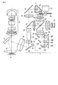
次に、図2により主として光源部17の具体的な光学系の構成例を示す。同図は、上記光源部17周辺の構成を平面的なレイアウトで表現したものである。
Next, FIG. 2 mainly shows a specific optical system configuration example of the
ここでは、同一の発光特性を有する複数、例えば3つの半導体レーザ20A〜20Cを設け、これら半導体レーザ20A〜20Cはいずれも青色、例えば波長約450[nm]のレーザ光を発振する。
Here, a plurality of, for example, three
これら半導体レーザ20A〜20Cの発振した青色光は、レンズ41A〜41Cを介してミラー22A〜22Cで全反射され、さらにレンズ42,43を介した後に上記ダイクロイックミラー23を透過し、レンズ群44を介してカラーホイール24に照射される。
The blue light oscillated by the
図3は、本実施形態におけるカラーホイール24の構成を示す。同図に示すようにカラーホイール24上では、例えば中心角約150°の円弧状の青色用拡散板24Bと、中心角約210°の円弧状の緑色蛍光体反射板24Gとが合わせて1つのリングを形成する。
FIG. 3 shows a configuration of the
本実施形態では、青色用拡散板24Bの中心角が、全周360°の1/3に相当する120°より大きく、且つ2/3に相当する240°より小さい角度として、例えば約150°と設定した。これにより、緑色蛍光体反射板24Gは中心角が残る約210°となるように設定した。このような角度設定とすることにより、後述する1画像フレームを構成するR,G,B各フィールドの時間幅を可変する場合に対処可能となる。
In the present embodiment, the central angle of the
図3では、カラーホイール24の基準位置を0°とし、カラーホイール24の回転により、半導体レーザ20A〜20Cからの青色光が照射される位置が、図中の矢印MVで示すように青色用拡散板24B及び緑色蛍光体反射板24Gで構成される周上を移動することを表している。
In FIG. 3, the reference position of the
カラーホイール24の青色用拡散板24Bが半導体レーザ20A〜20Cからの青色光の照射位置にある場合、照射された青色光は該拡散板24Bで拡散されながらカラーホイール24を透過し、背面側にあるレンズ50を介してミラー26で全反射される。
When the
さらに青色光は、レンズ51を介してミラー27で全反射され、レンズ52を介した後に上記ダイクロイックミラー28を透過し、レンズ46を介してインテグレータ29で輝度分布が略均一な光束とされた後にレンズ47を介し、ミラー30で全反射されて、レンズ48を介して上記ミラー18へ送られる。
ミラー18で全反射した青色光は、レンズ49を介してマイクロミラー素子16に照射される。そして、その青色光の反射光で青色成分の光像が形成され、レンズ49、上記投影レンズユニット19を介して外部へ投射される。
Further, the blue light is totally reflected by the
The blue light totally reflected by the
一方、緑色蛍光体反射板24Gが半導体レーザ20A〜20Cからの青色光の照射位置にある場合、その照射により例えば波長約530[nm]を中心とした波長帯の緑色光が励起され、励起された緑色光がカラーホイール24で反射された後、レンズ群44を介してダイクロイックミラー23でも反射される。
On the other hand, when the green
ダイクロイックミラー23で反射した緑色光は、レンズ45を介してさらにダイクロイックミラー28で反射され、レンズ46を介してインテグレータ29で輝度分布が略均一な光束とされた後にレンズ47を介し、ミラー30で全反射されて、レンズ48を介して上記ミラー18へ送られる。
ミラー18で全反射した緑色光は、レンズ49を介してマイクロミラー素子16に照射される。そして、その緑色光の反射光で緑色成分の光像が形成され、レンズ49、上記投影レンズユニット19を介して外部へ投射される。
The green light reflected by the
The green light totally reflected by the
また、上記LED21は、例えば波長620[nm]の赤色光を発生する。LED21の発した赤色光は、レンズ群53を介し、上記ダイクロイックミラー23を透過した後にレンズ45を介して上記ダイクロイックミラー28で反射され、さらにレンズ46を介してインテグレータ29で輝度分布が略均一な光束とされた後にレンズ47を介し、ミラー30で全反射されて、レンズ48を介して上記ミラー18へ送られる。
ミラー18で全反射した赤色光は、レンズ49を介してマイクロミラー素子16に照射される。そして、その赤色光の反射光で赤色成分の光像が形成され、レンズ49、上記投影レンズユニット19を介して外部へ投射される。
The
The red light totally reflected by the
次に上記実施形態の動作について説明する。
ここでは、投影するカラー画像1フレームを構成するB,R,Gの各原色画像を投影する期間(以下「Bフィールド、Rフィールド、Gフィールド」と称する)を等分し、その時間比を1:1:1とする。
Next, the operation of the above embodiment will be described.
Here, a period (hereinafter referred to as “B field, R field, and G field”) for projecting each primary color image of B, R, and G constituting one frame of the color image to be projected is equally divided, and the time ratio is 1 : 1: 1.
すなわち、定速回転するカラーホイール24の1回転360°に対して、Bフィールド、Rフィールド、及びGフィールドの時間比b:r:gは、カラーホイール24の中心角度に置換すると120°:120°:120°となる。
That is, for one rotation 360 ° of the
図4は、データプロジェクタ装置10の電源オン当初に実行される光源部17の輝度チェック処理の内容を示すフローチャートである。
同輝度チェック処理は、電源オン当初のみならず、このデータプロジェクタ装置10のユーザが手動で調整動作を選択した場合、及び一定時間、例えば10時間投影動作を続行した場合に自動的に実行するものとしてもよい。
FIG. 4 is a flowchart showing the content of the brightness check process of the
The brightness check process is automatically executed not only when the power is turned on, but also when the user of the
図4の処理は、CPU32がプログラムメモリ34に記憶していた動作プログラムを読出し、メインメモリ33上で展開した上で実行する。
The processing in FIG. 4 is executed after the
その処理当初にCPU32は、変数nに初期値「1」を代入する(ステップS101)。
At the beginning of the process, the
ついて、その時点の変数nの値、例えば「1」にしたがい、Bフィールドで半導体レーザ20A〜20Cを定格電流により発光させ、インテグレータ29の出力側における輝度Lbn(Lb1)を光センサLSにより測定させて、記録する(ステップS102)。
Then, according to the value of the variable n at that time, for example, “1”, the
ここで半導体レーザ20A〜20Cに流す定格電流は、プログラムメモリ34から読出して設定するもので、上述した如く工場出荷時にホワイトバランスがとれていた初期状態でB光を発光させるのに必要であった電流値である。
Here, the rated current passed through the
同様に、続くRフィールドでLED21を定格電流により発光させて、インテグレータ29の出力側における輝度Lrn(Lr1)を光センサLSにより測定させて、記録する(ステップS103)。
Similarly, the
ここで半導体レーザ20A〜20Cに流す定格電流も、プログラムメモリ34から読出して設定するもので、上述した如く工場出荷時にホワイトバランスがとれていた初期状態でR光を発光させるのに必要であった電流値である。
Here, the rated current flowing through the
さらに、続くGフィールドで半導体レーザ20A〜20Cを定格電流により発光させて、インテグレータ29の出力側における輝度Lgn(Lg1)を光センサLSにより測定させて、記録する(ステップS104)。
Further, in the subsequent G field, the
ここで半導体レーザ20A〜20Cに流す定格電流も、プログラムメモリ34から読出して設定するもので、上述した如く工場出荷時にホワイトバランスがとれていた初期状態でG光を発光させるのに必要であった電流値である。
Here, the rated current passed through the
ついて、変数nを「+1」更新設定する(ステップS105)。更新設定した変数nの値が「4」となっていないことを確認した上で(ステップS106)、再び上記ステップS102からの処理に戻る。 Subsequently, the variable n is updated and set to “+1” (step S105). After confirming that the value of the updated variable n is not "4" (step S106), the process returns to step S102 again.
こうして合計3フレームにわたってBフィールド、Rフィールド、及びGフィールドでの輝度Lb1,Lr1,Lg1,Lb2,Lr2,Lg2,Lb3,Lr3,Lg3を順次測定する。 Thus, the luminances Lb1, Lr1, Lg1, Lb2, Lr2, Lg2, Lb3, Lr3, and Lg3 in the B field, R field, and G field are sequentially measured over a total of three frames.
図5は、この輝度チェック処理実行時の光源部17の駆動状態を示す図である。
図5(A)は、マイクロミラー素子16に対して照射される光源光の色を示す。このように、1カラー画像フレームを時間的に等分のBフィールド、Rフィールド、Gフィールドの各期間で各色の光像を同時間ずつ形成するように制御する。
FIG. 5 is a diagram illustrating a driving state of the
FIG. 5A shows the color of the light source light emitted to the
図5(B)はLED21の駆動電流、図5(C)は半導体レーザ(B−LD)20A〜20Cの駆動電流を示している。フレーム当初のBフィールドでは、半導体レーザ20A〜20Cに青色画像用の定格駆動電流IstBが与えられ、上述した如くその時点のインテグレータ29出力側の輝度Lbn(Lb1〜Lb3)が測定される。
FIG. 5B shows the drive current of the
同様に、Rフィールドでは、LED21に赤色画像用の定格駆動電流IstRが与えられ、上述した如くその時点のインテグレータ29出力側の輝度Lrn(Lr1〜Lr3)が測定される。
Similarly, in the R field, the rated drive current IstR for red image is given to the
さらに、Gフィールドでは、半導体レーザ20A〜20Cに緑色画像用の定格駆動電流IstGが与えられ、上述した如くその時点のインテグレータ29出力側の輝度Lgn(Lg1〜Lg3)が測定される。
Further, in the G field, the rated drive current IstG for a green image is given to the
なお、上記図5(C)では、半導体レーザ20A〜20Cに与える青色画像用の定格駆動電流IstBと、緑色画像用の定格駆動電流IstGとが同値となった状態で示しているが、工場出荷時のホワイトバランスがとれた状態では緑色蛍光体反射板24Gの蛍光特性等により、予め緑色画像用の定格駆動電流IstGと緑色画像用の定格駆動電流IstGとが異なるものであってもよい。
In FIG. 5C, the blue image rated drive current IstB and the green image rated drive current IstG applied to the
上述した如く3フレームにわたって輝度値を測定した後、ステップS105で変数nをさらに「+1」更新設定した「4」とすると、続くステップS106でそれを確認し、輝度の測定を一旦停止する。 After the luminance value is measured over three frames as described above, if the variable n is further updated by “+1” to “4” in step S105, it is confirmed in the subsequent step S106, and the luminance measurement is temporarily stopped.
次いで、3フレーム分の測定値から定格電流で駆動した場合の各色輝度Lb,Lr,Lgの平均Lbav,Lrav,Lgavを求める(ステップS107)。 Next, the average Lbav, Lrav, Lgav of each color luminance Lb, Lr, Lg when driving with the rated current is obtained from the measured values for three frames (step S107).
これら求めた平均輝度Lbav,Lrav,Lgavに基づいて、最適なホワイトバランスが得られるような、上記定格駆動電流IstB,IstR,IstGを基準としたBフィールド、Rフィールド、及びGフィールドでの各駆動電流IB1,IR1,IG1を算出して設定する(ステップS108)。 Each drive in the B field, R field, and G field on the basis of the rated drive currents IstB, IstR, and IstG so that an optimum white balance can be obtained based on the obtained average luminances Lbav, Lrav, and Lgav. Currents IB1, IR1, and IG1 are calculated and set (step S108).
具体的には、本来のホワイトバランスに対して最も輝度の低下が著しい光源色を基準として、他の2つの光源色が最適なホワイトバランスとなるように調整を行なう。 Specifically, with reference to the light source color that exhibits the most significant decrease in luminance with respect to the original white balance, adjustment is performed so that the other two light source colors have the optimum white balance.
図6は、こうして新たな駆動電流を設定した場合の光源部17の駆動状態を示す図である。
図6(A)は、マイクロミラー素子16に対して照射される光源光の色を示す。
FIG. 6 is a diagram showing a driving state of the
FIG. 6A shows the color of the light source light emitted to the
図6(B)はLED21の駆動電流、図6(C)は半導体レーザ(B−LD)20A〜20Cの駆動電流を示している。フレーム当初のBフィールドでは、半導体レーザ20A〜20Cに青色画像用の定格駆動電流IstBよりも低い駆動電流IB1が与えられている。
6B shows the drive current of the
続くRフィールドでは、LED21に赤色画像用の定格駆動電流IstRよりも高い駆動電流IR1が与えられている。その後のGフィールドでは、半導体レーザ20A〜20Cに緑色画像用の定格駆動電流IstGよりも高い駆動電流IG1が与えられている。
In the subsequent R field, the
ここではLED21の発光輝度の低下が最も著しいものとして、LED21の駆動電流IR1を定格駆動電流IstRよりも大幅に高い値に設定すると共に、そのR光の新たな発光輝度に対して適正なホワイトバランスがとれるように、半導体レーザ20A〜20Cへの緑色画像用の駆動電流IG1も定格駆動電流IstGより若干高いものとして設定し、併せて半導体レーザ20A〜20Cへの青色画像用の駆動電流IB1は逆に定格駆動電流IstBよりも低い値に設定した例を示す。
Here, assuming that the decrease in the light emission luminance of the
こうして定格駆動電流での駆動に基づいた輝度の測定と、その測定結果に基づいて各色の劣化を勘案した最適なホワイトバランスが得られるような新たな駆動電流の設定とを行なうことで、通常の投影動作への準備を終える。 In this way, the brightness is measured based on driving at the rated drive current, and a new drive current is set so as to obtain an optimum white balance considering the deterioration of each color based on the measurement result. Finish preparations for projection.
加えて、ここではさらに上記算出した平均輝度値により光源部17の素子を構成する半導体レーザ20A〜20CとLED21の劣化判断を行なう。
すなわち、青色画像用に定格電流で半導体レーザ20A〜20Cを駆動した場合の平均輝度Lbavが、赤色画像用に定格電流でLED21を駆動した場合の平均輝度Lravに所定係数K1を乗じた積に比して低いか否かにより、半導体レーザ20A〜20Cのいずれかが実用限界を下回るほど劣化しているか否かを判断する(ステップS109)。
In addition, here, the deterioration of the
That is, the average luminance Lbav when the
ここで上記係数K1は、製品出荷時の半導体レーザ20A〜20Cの発する青色光の輝度特性とカラーホイール24の青色用拡散板24Bの透過特性、及びLED21の発する赤色光の輝度特性に応じて予めプログラムメモリ34に記録された係数である。
Here, the coefficient K1 is determined in advance according to the luminance characteristics of the blue light emitted from the
上記赤色画像用に定格電流でLED21を駆動した場合の平均輝度Lravを比較対象として、緑色画像用に定格電流で半導体レーザ20A〜20Cを駆動した場合の平均輝度Lgavではなく、青色画像用に定格電流で半導体レーザ20A〜20Cを駆動した場合の平均輝度Lbavから半導体レーザ20A〜20Cの劣化を判断するのは、カラーホイール24の緑色蛍光体反射板24Gに塗布された蛍光体が劣化を生じる可能性が高いのに対し、レーザ光が透過、拡散するだけのカラーホイール24の青色用拡散板24B部分が劣化することは実用上考え難いからである。
The average luminance Lrav when the
上記ステップS109で半導体レーザ20A〜20Cが所定値以上劣化していると判断した場合には、半導体レーザ20A〜20C、あるいは光源部17がアセンブリユニットで提供するものであればそのアセンブリユニット自体を交換するようなガイドメッセージを投影画像として出力させる(ステップS110)。
If it is determined in step S109 that the
次いで、青色画像用に定格電流で半導体レーザ20A〜20Cを駆動した場合の平均輝度Lbavが、緑色画像用に定格電流で半導体レーザ20A〜20Cを駆動した場合の平均輝度Lgavに所定係数K2を乗じた積に比して、高いか否かにより、カラーホイール24の緑色蛍光体反射板24G部分に塗布されている蛍光体が実用限界を下回るほど劣化しているか否かを判断する(ステップS111)。
Next, the average luminance Lbav when the
ここで上記係数K2は、製品出荷時の半導体レーザ20A〜20Cの発する青色光の輝度特性とカラーホイール24の青色用拡散板24Bの透過特性、及び同緑色蛍光体反射板24G部分に塗布された蛍光体の蛍光特性に応じて予めプログラムメモリ34に記録された係数である。
The coefficient K2 is applied to the luminance characteristics of blue light emitted from the
上記ステップS111でカラーホイール24の緑色蛍光体反射板24Gが所定値以上劣化していると判断した場合には、カラーホイール24、あるいは光源部17がアセンブリユニットで提供するものであればそのアセンブリユニット自体を交換するようなガイドメッセージを投影画像として出力させる(ステップS112)。
こうして図4の輝度チェック処理を完了した後、通常の投影動作に移行する。
If it is determined in step S111 that the
After completing the luminance check process of FIG.
以上詳記した如く本実施形態によれば、光源部17を構成する複数の光源素子や蛍光体を用いる場合に、個々の素子等が経年劣化を生じた場合にもそれを補償して、色再現性と投影画像の明るさを長く両立することが可能となる。
As described above in detail, according to the present embodiment, when a plurality of light source elements and phosphors constituting the
なお上記実施形態においては、光センサLSをインテグレータ29の出力側に配置し、青色光、赤色光、及び緑色光の各発光輝度を1つの光センサLSで検知するものとした。
In the above embodiment, the light sensor LS is arranged on the output side of the
これにより、必要な回路素子の構成を極力簡素化しながらも、必要な全色光の発光輝度を検知することが可能となり、装置全体の製造コストの増大を最小限に抑えることができる。 As a result, it is possible to detect the light emission luminance of all the necessary color lights while simplifying the configuration of the necessary circuit elements as much as possible, and the increase in the manufacturing cost of the entire apparatus can be minimized.
また上記実施形態では、輝度チェックの結果に基づいて、1フレームを構成するR,G,Bの各フィールド期間の時間幅を変えることなく、光源側の発光素子の発光強度を可変調整することで対処するものとした。
これにより、投影画像処理部15及びマイクロミラー素子16を含む光像を形成する側の回路での動作タイミングを可変する必要がなく、制御が容易になる。
In the above embodiment, the light emission intensity of the light emitting element on the light source side is variably adjusted based on the result of the luminance check without changing the time width of each field period of R, G, and B constituting one frame. It was supposed to be dealt with.
As a result, it is not necessary to vary the operation timing in the circuit on the side that forms the optical image including the projection
なお、上記図4の処理では、ステップS109でLED21の発光輝度に比して半導体レーザ20A〜20Cの発光輝度の値が所定の割合以下となっているか否かにより半導体レーザ20A〜20Cのいずれかの発光輝度が実用限界を下回るほど劣化したかどうかを判断するものとしたが、LED21が半導体レーザ20A〜20Cとともに劣化していた場合には、上記ステップS109で示した判断処理ではそれらの劣化を検出することができない。
In the process of FIG. 4 described above, one of the
したがって、LED21と半導体レーザ20A〜20Cそれぞれに輝度を測定してその絶対値を本来の輝度と比較するものとしてもよく、そのような処理を加えることで、LED21と半導体レーザ20A〜20Cそれぞれの輝度劣化を正確に判断できる。そして、上述のように半導体レーザ、LED21、緑色蛍光体反射板24G部分に塗布されている蛍光体のうちいずれかが所定値以上劣化していた場合は、交換指示等を報知することができる。
Therefore, the luminance of each of the
なお、上記図6に示したような、光源側の発光素子の駆動電流を制御することで発光強度を可変調整するのではなく、各発光素子の発光電力は一定としながらも、1フレームを構成するR,G,Bの各フィールド期間の時間幅を変えることで対処するものとしてもよい。 As shown in FIG. 6, the light emission intensity is not variably adjusted by controlling the drive current of the light emitting element on the light source side, but one frame is formed while the light emission power of each light emitting element is constant. This may be dealt with by changing the time width of each of the R, G, and B field periods.
図7は、上記ステップS108での処理に代えて、1フレームを構成するR,G,Bの各フィールド期間の時間幅を変えるように設定した場合の光源部17の駆動例を示す。
FIG. 7 shows an example of driving the
ここでは、輝度チェック処理後も上記図5で説明した状態と同様に半導体レーザ20A〜20C及びLED21共に定格電流IstB,IstR,IstGでの駆動を継続しているが、各フィールドの時間幅を大きく変更している。
Here, even after the luminance check process, the
すなわち、Bフィールドは、回転するカラーホイール24の中心角度で120°分に相当する時間幅から大きく減少して78°分に相当する時間幅となっている。続くRフィールドは、回転するカラーホイール24の中心角度で120°分に相当する時間から大きく増加して150°分に相当する時間幅となっている。その後のGフィールドは、回転するカラーホイール24の中心角度で120°分に相当する時間から若干増加して132°分に相当する時間幅となっている。
That is, the B field has a time width corresponding to 78 °, which is greatly reduced from the time width corresponding to 120 ° at the central angle of the
上記CPU32は、投影光処理部31により半導体レーザ20A〜20C及びLED21の駆動電流と駆動タイミングとを上述した如く制御させるのと同時に、投影画像処理部15及びマイクロミラー素子16を含む投影系で光像を形成するタイミングを上記光源光の調整内容と同期させる必要がある。
The
このように、光源の素子を駆動する電力で発光強度を調整するのではなく、各発光素子を定電力で駆動しながら1フレームを構成する各フィールド単位でその時間幅を調整することにより、画像を投影する側の時間制御が複雑になる一方で、各発光素子は常に一定の電力で駆動されるために、発光素子の劣化を早めるような虞がなく、発光素子の長寿命化を図ることができる。 In this way, the light emission intensity is not adjusted by the power for driving the light source elements, but the time width is adjusted for each field constituting one frame while driving each light emitting element at a constant power, thereby obtaining an image. While the time control on the projection side is complicated, each light emitting element is always driven with a constant power, so there is no risk of accelerating the deterioration of the light emitting element, and the life of the light emitting element is extended. Can do.
なお上記実施形態では、光センサLSをインテグレータ29の出力側に設けることで、B,R,G各色の発光強度を検知することが可能であるものとして説明したが、装置の設計及び発光素子の特性上、発光素子である半導体レーザ20A〜20C、またはLED21のいずれか一方が他方に比して特に発光強度の低下が著しいか、あるいは劣化を生じ易いと思われる場合には、光センサLSを当該発光素子の発光部位に直接対向するように配置してもよい。
In the above-described embodiment, it has been described that the light emission intensity of each color of B, R, and G can be detected by providing the optical sensor LS on the output side of the
また上記実施形態では、半導体レーザ20A〜20CまたはLED21のいずれか一方を選択的に駆動してB(青色)光、R(赤色)光、及びG(緑色光)によるBフィールド、Rフィールド、及びGフィールドから1カラー画像フレームが構成されるものとして説明したが、本発明はこれに限らず、複数の発光素子を同時に発光させてその混色による画像フィールドを含むようにしてもよい。
In the above-described embodiment, any one of the
具体的には、例えばB(青色)光とR(赤色)光Bとを同時に発光させることで混色によりM(マゼンタ)色の光像を投影する画像フィールドが1画像フレーム中に存在するものとしてもよいし、G(緑色)光とR(赤色)光Bとを同時に発光させることで混色によりY(黄)色の光像を投影する画像フィールドが1画像フレーム中に存在するものとしてもよい。 Specifically, for example, it is assumed that an image field that projects a light image of M (magenta) color by mixing B (blue) light and R (red) light B simultaneously is present in one image frame. Alternatively, an image field for projecting a Y (yellow) light image by color mixture by simultaneously emitting G (green) light and R (red) light B may be present in one image frame. .
こうした混色による画像フィールドを設けることで、色の表現性や画像の明るさをより増加させることができ、結果としてデータプロジェクタ装置10が使用される環境に応じた投影が実施できる。
By providing such an image field by color mixture, it is possible to further increase the color expression and the brightness of the image, and as a result, it is possible to perform projection according to the environment in which the
(第2の実施形態)
以下本発明をDLP(登録商標)方式のデータプロジェクタ装置に適用した場合の第2の実施形態について図面を参照して説明する。
(Second Embodiment)
A second embodiment in which the present invention is applied to a DLP (registered trademark) data projector will be described below with reference to the drawings.
図8は、本実施形態に係るデータプロジェクタ装置10′が備える電子回路の概略機能構成を示すブロック図である。
なお、データプロジェクタ装置10′を構成する基本的な電子回路、及び特に光源部17の具体的な光学系の構成例については、ほぼ上記図1及び図2に示した内容と同様であるため、同一部分には同一符号を付してその説明は省略する。
FIG. 8 is a block diagram showing a schematic functional configuration of an electronic circuit provided in the
The basic electronic circuit that constitutes the data projector device 10 ', and in particular, the specific optical system configuration example of the
なお、光源部17は上記図1及び図2で示した光センサLSを有さない点で第1の実施形態とは異なる。
The
また、CPU32に代わるCPU32′は、内部に、発光時間をカウントするタイマー32aを備える。
In addition, a
さらに、プログラムメモリ34に代わるプログラムメモリ34′は、発光時間ログ記憶部34aと駆動電流変換テーブル34bとを備える。発光時間ログ記憶部34aは、光源部17の半導体レーザ20A〜20C及びLED21の積算発光時間を保持する。駆動電流変換テーブル34bは、半導体レーザ20A〜20CとLED21それぞれの積算発光時間に対応した基準駆動電流値をルックアップテーブルの形で予め記憶している。この駆動電流変換テーブル34bの記憶内容は、半導体レーザ20A〜20C及びLED21の経時変化特性から、必要とされる発光輝度を得るための基準駆動電流値が予測値として記憶されたものである。
Furthermore, a
次に上記実施形態の動作について説明する。
なお、本実施形態においては、データプロジェクタ装置10′が複数のカラー投影モードとして、例えばノーマルモード、プレゼンテーションモード、シアターモード、グラフィックスモード、及び黒板モードから1つを選択することが可能であるものとする・
ノーマルモードは、本データプロジェクタ装置10′のカラー投影モードの基準として用いるもので、色表現を重視した設定とする。
プレゼンテーションモードは、明るい場所での一般的なプレゼンテーションに適した、明るさを重視した設定とする。
シアターモードは、映画の暗部の表現を重視した設定とする。
グラフィックスモードは、写真などが自然に見えるように階調表現を重視した設定とする。
黒板モードは、黒板に画像を投影する場合でも投影内容がはっきりと判別可能となる設定とする。
Next, the operation of the above embodiment will be described.
In the present embodiment, the
The normal mode is used as a reference for the color projection mode of the data projector apparatus 10 ', and is set with an emphasis on color expression.
The presentation mode is set so that brightness is suitable for general presentation in a bright place.
The theater mode is set with emphasis on the expression of the dark part of the movie.
The graphics mode is set so as to emphasize gradation expression so that a photograph or the like looks natural.
The blackboard mode is set so that the projection content can be clearly discriminated even when an image is projected onto the blackboard.
これらノーマルモード以外の各カラーモードに関して、ノーマルモード時を基準とした半導体レーザ20A〜20CとLED21それぞれの駆動電流値の違いに基づく投影時間の換算係数が予めプログラムメモリ34′に記憶されていものとする。
For each of the color modes other than the normal mode, a projection time conversion coefficient based on the difference between the drive current values of the
図4は、データプロジェクタ装置10′の電源オン後に投影動作と平行して実行される光源部17の駆動制御の処理内容を示すものである。この図9の処理は、CPU32′がプログラムメモリ34′に記憶していた動作プログラムを読出し、メインメモリ33上で展開した上で実行する。
FIG. 4 shows the processing content of the drive control of the
その処理当初にCPU32′は、駆動時間ログ記憶部34aを読出し、半導体レーザ20A〜20CとLED21それぞれの積算発光時間を読出す(ステップS301)。
At the beginning of the process, the CPU 32 'reads the drive time log storage unit 34a, and reads the integrated light emission times of the
そして、読出した積算発光時間に応じて駆動電流変換テーブル34bを参照し、半導体レーザ20A〜20C及びLED21それぞれの基準駆動電流を読出す(ステップS302)。
Then, the reference drive currents of the
これら読出したそれぞれの基準駆動電流値を投影光処理部31に設定する(ステップS303)。その上でさらに、前回電源をオフした時点で設定されていたカラー投影モードの情報をプログラムメモリ34′から読出す(ステップS304)。 These read reference drive current values are set in the projection light processing unit 31 (step S303). In addition, information on the color projection mode that was set when the power was last turned off is read from the program memory 34 '(step S304).
読出したカラー投影モードの情報を基に、半導体レーザ20A〜20CによるB(青色)光、及びG(緑色)光発光時の駆動電流の各割り増し比率と、LED21によるR(赤色)光発光時の駆動電流の割り増し比率とを上記設定した基準駆動電流に乗算してその積を新たな駆動電流として投影光処理部31で設定させる(ステップS305)。
Based on the read information on the color projection mode, the respective drive currents when B (blue) light and G (green) light are emitted by the
さらに、CPU32′内のタイマー32aをリセットして投影時間のカウントを開始させる(ステップS306)。
Further, the
以後、設定されたカラー投影モードでの投影動作を平行して実行しながら、併せて操作部35により電源オフのキー操作がなされたか否か(ステップS307)、カラー投影モードの変更指示の操作がなされたか否か(ステップS308)、を繰返し判断することで、これらの操作がなされるのを待機する。 Thereafter, while the projection operation in the set color projection mode is executed in parallel, whether or not the power-off key operation is performed by the operation unit 35 (step S307), and the operation of changing the color projection mode is performed. Whether or not these operations have been performed is repeatedly determined (step S308) to wait for these operations to be performed.
投影動作途中でカラー投影モードの変更指示の操作がなされた場合、上記ステップS308でそれを判断し、その時点でのタイマー32aの計時値を読出す(ステップS309)。
If an operation to change the color projection mode is performed during the projection operation, it is determined in step S308, and the time value of the
次いで、読出した計時値とそれまで設定されていたカラー投影モードとにより、ノーマルモード時に換算した半導体レーザ20A〜20CとLED21それぞれの発光時間を算出し、算出した発光時間を用いて発光時間ログ記憶部34aの内容を更新設定する(ステップS310)。
Next, the light emission times of the
次いで、上記操作された通り、あらたなカラー投影モードへの切換処理を実行した上で
(ステップS311)、再び上記ステップS306からの処理に戻る。
Next, as described above, after switching to a new color projection mode is executed (step S311), the process returns to step S306 again.
また、上記ステップS307で電源オフを指示する操作がなされと判断すると、その時点でのタイマー32aの計時値を読出す(ステップS312)。
If it is determined in step S307 that an operation for instructing power-off is performed, the time value of the
次いで、読出した計時値とそれまで設定されていたカラー投影モードとにより、ノーマルモード時に換算した半導体レーザ20A〜20CとLED21それぞれの発光時間を算出し、算出した発光時間を用いて発光時間ログ記憶部34aの内容を更新設定する(ステップS313)。
Next, the light emission times of the
次いで、上記操作された通り、アフタークーリング処理を含むこのデータプロジェクタ装置10′の電源をオフするための処理を実行した上で(ステップS314)、以上でこの図9の処理を終了する。 Next, as described above, the process for turning off the power of the data projector apparatus 10 'including the after cooling process is executed (step S314), and the process of FIG.
以上詳述した如く本実施形態によれば、特に直接半導体レーザ20A〜20CやLED21の発光輝度を検知するセンサ等の回路素子を設けることなく、発光素子の経年劣化の度合が予測可能であれば、複数の光源や蛍光体医を用いる場合に個々の素子等が経年劣化を生じた場合にもそれを補償し、色再現性と投影画像の明るさを長く両立することが可能となる。
As described in detail above, according to the present embodiment, the degree of aging of the light emitting element can be predicted without providing a circuit element such as a sensor for directly detecting the light emission luminance of the
加えて上記実施形態では、複数のカラー投影モードから1つを選択可能とし、各カラー投影モードでの発光素子の発光時間を、基準となる1つのカラー投影モードに換算した上で発光素子毎に発光時間を積算して管理するものとした。 In addition, in the above-described embodiment, one of a plurality of color projection modes can be selected, and the light emission time of the light emitting element in each color projection mode is converted into one reference color projection mode, and then is set for each light emitting element. The emission time was integrated and managed.
これにより、積算発光時間の管理が容易となると共に、カラー投影モード毎に異なる、複数の発光素子の消耗度合も勘案して、正確な管理手法が確立できる。 As a result, the management of the integrated light emission time is facilitated, and an accurate management method can be established in consideration of the degree of wear of the plurality of light emitting elements, which is different for each color projection mode.
なお、上記第1及び第2の実施形態はいずれも、半導体レーザ20A〜20Cで青色のレーザ光を発振してカラーホイール24により青色光及び緑色光を発生させる一方で、LED21で赤色光を発生するものとして説明したが、本発明はこれに限らず、1つの光源で発生しうる原色光の輝度バランスが実用に適さない場合に、他の光源を用いてそれを補償するような、複数種類の光源を用いる光源部、及びそのような光源部を用いる投影装置であれば同様に適用可能である。
In both the first and second embodiments, the
また、上記各実施形態は共に本発明をDLP(登録商標)方式のデータプロジェクタ装置に適用した場合について説明したものであるが、例えば透過型のモノクロ液晶パネルを用いて光像を形成する液晶プロジェクタ等にも同様に本発明を適用することができる。 In each of the embodiments described above, the present invention is applied to a DLP (registered trademark) type data projector apparatus. For example, a liquid crystal projector that forms a light image using a transmissive monochrome liquid crystal panel. The present invention can be similarly applied to the above.
その他、本発明は上述した実施形態に限定されるものではなく、実施段階ではその要旨を逸脱しない範囲で種々に変形することが可能である。また、上述した実施形態で実行される機能は可能な限り適宜組み合わせて実施しても良い。上述した実施形態には種々の段階が含まれており、開示される複数の構成要件による適宜の組み合せにより種々の発明が抽出され得る。例えば、実施形態に示される全構成要件からいくつかの構成要件が削除されても、効果が得られるのであれば、この構成要件が削除された構成が発明として抽出され得る。 In addition, the present invention is not limited to the above-described embodiments, and various modifications can be made without departing from the scope of the invention in the implementation stage. Further, the functions executed in the above-described embodiments may be combined as appropriate as possible. The above-described embodiment includes various stages, and various inventions can be extracted by an appropriate combination of a plurality of disclosed constituent elements. For example, even if some constituent requirements are deleted from all the constituent requirements shown in the embodiment, if the effect is obtained, a configuration from which the constituent requirements are deleted can be extracted as an invention.
10,10′…データプロジェクタ装置、11…入出力コネクタ部、12…入出力インタフェース(I/F)、13…画像変換部(スケーラ)、14…ビデオRAM、15…投影画像処理部、16…マイクロミラー素子(SLM)、17…光源部、18…ミラー、19…投影レンズユニット、20…(B発光)半導体レーザ、21…(R発光)LED、22…ミラー、23…ダイクロイックミラー、24…カラーホイール、24B…青色用拡散板、24G…緑色蛍光体反射板、25…モータ(M)、26,27…ミラー、28…ダイクロイックミラー、29…インテグレータ、30…ミラー、31…投影光処理部、32,32′…CPU、32…タイマー、33…メインメモリ、34,34′…プログラムメモリ、34a…発光時間ログ記憶部、34b…駆動電流変換テーブル(TB)、35…操作部、36…音声処理部、37…スピーカ部、41A〜41C,42,43…レンズ、44…レンズ群、45〜52…レンズ、53…レンズ群、SB…システムバス、LS…光センサ。
DESCRIPTION OF
Claims (11)
上記第1の波長帯域とは異なる第2の波長帯域の光源光を発生する第2の光源と、
上記第1の光源から発光され照射された第1の波長帯域の光源光を透過する透過部と、上記第1の波長帯域と上記第2の波長帯域とは異なる波長帯域を前記第1の光源が発生した光源光を用い発生させ反射する反射部を有するカラーホイールと、
上記カラーホイール及び第2の光源から発生する各光源光が循環的に発生するように上記第1及び第2の光源と上記カラーホイールの駆動タイミングを制御する第1の光源制御手段と、
上記カラーホイール及び第2の光源から発生する各光源光の光強度を検出する検出手段と、
上記検出手段による上記カラーホイール及び第2の光源から発生する各光源光における光強度値をそれぞれ記憶しておく記憶手段と、
上記記憶手段に記憶された各光源光の光強度値に対する上記検出手段での検出結果に基づいて上記第1及び第2の光源の発光状態を調整する第2の光源制御手段と
を具備したことを特徴とする光源装置。 A first light source that emits light in a first wavelength band;
A second light source for generating light source light in a second wavelength band different from the first wavelength band;
The first of the first and the transmitting portion for transmitting light source light in a wavelength band of said first said wavelength band different from the wavelength band and the second wavelength band of the first light source emitted irradiated from the light source A color wheel having a reflecting portion that generates and reflects light source light generated by
First light source control means for controlling the drive timing of the first and second light sources and the color wheel so that each light source light generated from the color wheel and the second light source is generated cyclically;
Detection means for detecting light intensity of each light source light generated from the color wheel and the second light source;
Storage means for storing light intensity values in the respective light source lights generated from the color wheel and the second light source by the detection means;
Second light source control means for adjusting the light emission state of the first and second light sources based on the detection result of the detection means for the light intensity value of each light source light stored in the storage means; A light source device characterized by the above.
上記第1の波長帯域とは異なる第2の波長帯域の光源光を発生する第2の光源と、
上記第1の光源から発光され照射された第1の波長帯域の光源光を透過する透過部と、上記第1の波長帯域と上記第2の波長帯域とは異なる波長帯域を前記第1の光源が発生した光源光を用い発生させ反射する反射部を有するカラーホイールと、
上記カラーホイール及び第2の光源から発生する各光源光が循環的に発生するように上記第1及び第2の光源と上記カラーホイールの駆動タイミングを制御する第1の光源制御手段と、
上記カラーホイール及び第2の光源から発生する各光源光の光強度を検出する検出手段と、
上記検出手段による上記カラーホイール及び第2の光源から発生する各光源光における光強度値をそれぞれ記憶しておく記憶手段と、
上記記憶手段に記憶された各光源の光強度に対する上記検出手段での検出結果に基づいて上記第1及び第2の光源の発光状態を調整する第2の光源制御手段と、
画像信号を入力する入力手段と、
上記第1及び第2の光源制御手段での制御に基づいて出射される光源光を用い、上記入力手段で入力する画像信号に対応したカラーの光像を形成して投影する投影手段と
を具備したことを特徴とする投影装置。 A first light source that emits light in a first wavelength band;
A second light source for generating light source light in a second wavelength band different from the first wavelength band;
The first a first transmitting unit which transmits source light wavelength band, the first said wavelength band different from the wavelength band and the second wavelength band of the first light source emitted irradiated from the light source A color wheel having a reflecting portion that generates and reflects light source light generated by
First light source control means for controlling the drive timing of the first and second light sources and the color wheel so that each light source light generated from the color wheel and the second light source is generated cyclically;
Detection means for detecting light intensity of each light source light generated from the color wheel and the second light source;
Storage means for storing light intensity values in the respective light source lights generated from the color wheel and the second light source by the detection means;
Second light source control means for adjusting the light emission state of the first and second light sources based on the detection result of the detection means for the light intensity of each light source stored in the storage means;
An input means for inputting an image signal;
And projection means for forming and projecting a color light image corresponding to an image signal input by the input means, using light source light emitted based on the control by the first and second light source control means. A projection apparatus characterized by that.
上記第2の光源制御手段は、上記検出手段での検出結果に基づいて、上記カラーホイールで発生する複数色の光源光、及び上記第2の光源の発光による光源光すべての発光状態を調整する
ことを特徴とする請求項4記載の投影装置。 The detection means is provided at a position where light sources of a plurality of colors generated by the color wheel and light sources of light emitted by the second light source are emitted in common.
The second light source control means adjusts the light emission state of all the light source lights generated by the color wheel and the light from the second light source based on the detection result of the detection means. The projection apparatus according to claim 4.
上記カラーホイール及び第2の光源から発生する各光源光が循環的に発生するように上記第1及び第2の光源と上記カラーホイールの駆動タイミングを制御する第1の光源制御工程と、
上記記憶部に記憶された各光源光の光強度値に対する上記検出部での検出結果に基づいて上記第1及び第2の光源の発光状態を調整する第2の光源制御工程と
を有したことを特徴とする投影方法。 A first light source that emits light in a first wavelength band, a second light source that generates light source light in a second wavelength band different from the first wavelength band, and a first light source that is emitted and irradiated from the first light source . a transmitting unit which transmits source light first wavelength band, reflections reflected is generated using the source light wherein the different wavelength bands the first light source is generated from the first wavelength band and said second wavelength band A color wheel having a section, a detection section for detecting the light intensity of each light source light generated from the light source light generation section and the second light source, and each light source light generated from the color wheel and the second light source by the detection section. A storage unit that stores light intensity values; an input unit that inputs an image signal; and a projection unit that forms and projects a color light image corresponding to the image signal input from the input unit using light source light. A projection method with the projection apparatus provided Te,
A first light source control step of controlling the drive timing of the first and second light sources and the color wheel so that each light source light generated from the color wheel and the second light source is generated cyclically;
And a second light source control step of adjusting the light emission state of the first and second light sources based on the detection result of the detection unit with respect to the light intensity value of each light source light stored in the storage unit. A projection method characterized by
上記カラーホイール及び第2の光源から発生する各光源光が循環的に発生するように上記第1及び第2の光源と上記カラーホイールの駆動タイミングを制御する第1の光源制御ステップと、
上記記憶部に記憶された各光源光の光強度値に対する上記検出部での検出結果及に基づいて上記第1及び第2の光源の発光状態を調整する第2の光源制御ステップと
をコンピュータに実行させる、コンピュータが読取可能なプログラム。 A first light source that emits light in a first wavelength band, a second light source that generates light source light in a second wavelength band different from the first wavelength band, and a first light source that is emitted and irradiated from the first light source . a transmitting unit which transmits source light first wavelength band, reflections reflected is generated using the source light wherein the different wavelength bands the first light source is generated from the first wavelength band and said second wavelength band A color wheel having a section, a detection section for detecting light intensity of each light source light generated from the color wheel and the second light source, and a light intensity in each light source light generated from the color wheel and the second light source by the detection section. A storage unit for storing values, an input unit for inputting an image signal, and a projection unit for forming and projecting a color light image corresponding to the image signal input by the input unit using light source light Computer built into the projector A program Yuta to be executed,
A first light source control step for controlling the drive timing of the first and second light sources and the color wheel so that each light source light generated from the color wheel and the second light source is generated cyclically;
A second light source control step for adjusting a light emission state of the first and second light sources based on a detection result of the detection unit with respect to a light intensity value of each light source light stored in the storage unit; A computer-readable program to be executed.
Priority Applications (6)
| Application Number | Priority Date | Filing Date | Title |
|---|---|---|---|
| JP2009192595A JP5625287B2 (en) | 2009-08-21 | 2009-08-21 | Light source device, projection device, projection method and program |
| US12/840,496 US8979278B2 (en) | 2009-08-21 | 2010-07-21 | Light source device and projection apparatus which adjusts a light emission state of first and second light sources based on one of detected light intensity values and an accumulated light emission time, and projection method and non-transitory storage medium |
| CN2010102605871A CN101995749B (en) | 2009-08-21 | 2010-08-20 | Light source device, projection apparatus and projection method |
| TW099127850A TWI524127B (en) | 2009-08-21 | 2010-08-20 | Light source device, projection apparatus, projection method, and storage medium |
| CN2012102416559A CN102749797A (en) | 2009-08-21 | 2010-08-20 | Light source device, projection apparatus, projection method, and storage medium |
| HK11106969.1A HK1153084A1 (en) | 2009-08-21 | 2011-07-06 | Light source device, projection apparatus and projection method |
Applications Claiming Priority (1)
| Application Number | Priority Date | Filing Date | Title |
|---|---|---|---|
| JP2009192595A JP5625287B2 (en) | 2009-08-21 | 2009-08-21 | Light source device, projection device, projection method and program |
Related Child Applications (3)
| Application Number | Title | Priority Date | Filing Date |
|---|---|---|---|
| JP2013079067A Division JP5637405B2 (en) | 2013-04-05 | 2013-04-05 | Rotating body, projection apparatus, projection method and program |
| JP2013079066A Division JP5652500B2 (en) | 2013-04-05 | 2013-04-05 | Light source device, projection device, projection method and program |
| JP2014202993A Division JP5929995B2 (en) | 2014-10-01 | 2014-10-01 | Rotating body and projection device |
Publications (3)
| Publication Number | Publication Date |
|---|---|
| JP2011044367A JP2011044367A (en) | 2011-03-03 |
| JP2011044367A5 JP2011044367A5 (en) | 2011-11-17 |
| JP5625287B2 true JP5625287B2 (en) | 2014-11-19 |
Family
ID=43605107
Family Applications (1)
| Application Number | Title | Priority Date | Filing Date |
|---|---|---|---|
| JP2009192595A Active JP5625287B2 (en) | 2009-08-21 | 2009-08-21 | Light source device, projection device, projection method and program |
Country Status (5)
| Country | Link |
|---|---|
| US (1) | US8979278B2 (en) |
| JP (1) | JP5625287B2 (en) |
| CN (2) | CN102749797A (en) |
| HK (1) | HK1153084A1 (en) |
| TW (1) | TWI524127B (en) |
Families Citing this family (69)
| Publication number | Priority date | Publication date | Assignee | Title |
|---|---|---|---|---|
| US8520290B2 (en) * | 2007-08-16 | 2013-08-27 | Silicon Quest Kabushiki Kaisha | Display system for higher grayscale with a varying light source |
| JP4975797B2 (en) * | 2009-10-14 | 2012-07-11 | シャープ株式会社 | LIGHTING DEVICE, VEHICLE LIGHT, AND VEHICLE |
| WO2011092841A1 (en) | 2010-01-29 | 2011-08-04 | Necディスプレイソリューションズ株式会社 | Illumination optical system and projector using same |
| US9046753B2 (en) * | 2010-05-28 | 2015-06-02 | Nec Display Solutions, Ltd. | Projector having plural light source boxes each having associated solid-state light source, photodetector, and drive unit |
| JP5427719B2 (en) * | 2010-07-21 | 2014-02-26 | 日立コンシューマエレクトロニクス株式会社 | Projection display device |
| JP5534331B2 (en) * | 2010-07-30 | 2014-06-25 | カシオ計算機株式会社 | Light source unit and projector |
| JP2012088451A (en) * | 2010-10-18 | 2012-05-10 | Sony Corp | Lighting device and display device |
| JP5741795B2 (en) | 2010-11-09 | 2015-07-01 | セイコーエプソン株式会社 | Projector and control method thereof |
| US9300929B2 (en) * | 2011-01-24 | 2016-03-29 | Seiko Epson Corporation | Illumination device and projector |
| JP5821246B2 (en) * | 2011-04-01 | 2015-11-24 | セイコーエプソン株式会社 | Light source device and projector |
| US9500935B2 (en) * | 2011-04-18 | 2016-11-22 | Nec Display Solutions, Ltd. | Projection image display device |
| CN102841492A (en) * | 2011-06-21 | 2012-12-26 | 宏碁股份有限公司 | Electronic device and control method thereof |
| US9448416B2 (en) | 2011-07-13 | 2016-09-20 | Nec Display Solutions, Ltd. | Light source device and projection-type display device |
| JP5820983B2 (en) * | 2011-08-01 | 2015-11-24 | パナソニックIpマネジメント株式会社 | Projection display device |
| JP5915035B2 (en) * | 2011-09-05 | 2016-05-11 | カシオ計算機株式会社 | Projection apparatus and projection control method |
| CN102809881B (en) * | 2011-09-22 | 2015-01-21 | 深圳市绎立锐光科技开发有限公司 | Light source system and applied projection system thereof |
| JP5862938B2 (en) * | 2011-10-03 | 2016-02-16 | カシオ計算機株式会社 | Light source device and projector |
| JP5494610B2 (en) * | 2011-10-17 | 2014-05-21 | カシオ計算機株式会社 | Projection apparatus, projection control method, and program |
| TW201317705A (en) * | 2011-10-31 | 2013-05-01 | Delta Electronics Inc | Light emitting module and display device |
| CN103091953A (en) * | 2011-10-31 | 2013-05-08 | 台达电子工业股份有限公司 | Light emitting module and display device |
| JP6098074B2 (en) * | 2011-10-31 | 2017-03-22 | 株式会社リコー | Projection display device |
| JP5799756B2 (en) | 2011-11-02 | 2015-10-28 | セイコーエプソン株式会社 | projector |
| CN103207507B (en) | 2012-01-11 | 2015-07-08 | 中强光电股份有限公司 | Light source module and projector |
| JP2013160894A (en) | 2012-02-03 | 2013-08-19 | Ricoh Co Ltd | Light source device, and projection display device |
| JP5915229B2 (en) * | 2012-02-13 | 2016-05-11 | セイコーエプソン株式会社 | projector |
| JP2013182142A (en) * | 2012-03-02 | 2013-09-12 | Mitsubishi Electric Corp | Multi-screen display device |
| JP6064346B2 (en) * | 2012-03-19 | 2017-01-25 | カシオ計算機株式会社 | Projection apparatus, program, and control method of projection apparatus |
| US9482413B2 (en) | 2012-04-05 | 2016-11-01 | Koninklijke Philips N.V. | Colour sequential lighting device |
| TW201348842A (en) * | 2012-05-18 | 2013-12-01 | Delta Electronics Inc | Phosphor wheel and illumination system with the same |
| CN102799054B (en) * | 2012-06-20 | 2015-06-10 | 苏州佳世达光电有限公司 | Light source module, projector and setting method of projector |
| JP6047968B2 (en) | 2012-07-17 | 2016-12-21 | セイコーエプソン株式会社 | Projector and light emission control method in projector |
| JP6019859B2 (en) * | 2012-07-17 | 2016-11-02 | セイコーエプソン株式会社 | Projector and light emission control method in projector |
| KR101503977B1 (en) * | 2012-07-31 | 2015-03-19 | 삼성전기주식회사 | Apparatus And Method for Driving Illumination of Light Emitting Diode |
| JP6028440B2 (en) * | 2012-07-31 | 2016-11-16 | 三菱電機株式会社 | Image display device and light source control method |
| CN103792764B (en) | 2012-10-31 | 2016-02-10 | 中强光电股份有限公司 | Illuminator |
| JP6000097B2 (en) * | 2012-12-06 | 2016-09-28 | 三菱電機株式会社 | Laser light source projector |
| JP6186752B2 (en) * | 2013-03-01 | 2017-08-30 | カシオ計算機株式会社 | Light source device and projection device |
| JP6205835B2 (en) * | 2013-05-14 | 2017-10-04 | 株式会社リコー | LIGHTING DEVICE, PROJECTION DEVICE PROVIDED WITH THIS LIGHTING DEVICE, AND LIGHTING METHOD |
| JP2014240912A (en) * | 2013-06-12 | 2014-12-25 | パナソニック株式会社 | Luminaire and image display device |
| DE102013219930A1 (en) * | 2013-10-01 | 2015-04-02 | Osram Gmbh | Lighting device with measuring device and method for operating this lighting device |
| JP5811248B2 (en) | 2013-10-15 | 2015-11-11 | ウシオ電機株式会社 | Light source device and projector |
| JP6452027B2 (en) * | 2013-10-23 | 2019-01-16 | 株式会社リコー | Light source device and image projection device provided with the same |
| JP6234212B2 (en) * | 2013-12-19 | 2017-11-22 | 富士フイルム株式会社 | Endoscope light source device and endoscope system using the same |
| JP2015135465A (en) * | 2013-12-20 | 2015-07-27 | カシオ計算機株式会社 | Light source unit and projection device |
| JP6187276B2 (en) * | 2014-01-20 | 2017-08-30 | ソニー株式会社 | Light source device and image display device |
| US10732495B2 (en) | 2014-05-02 | 2020-08-04 | Coretronic Corporation | Illumination system, projection apparatus and method for driving illumination system |
| TWI504832B (en) * | 2014-05-02 | 2015-10-21 | Coretronic Corp | Illumination system and projection apparatus |
| CN105093791A (en) * | 2014-05-16 | 2015-11-25 | 中强光电股份有限公司 | Projection device and protection method of projection device |
| CN105321445B (en) | 2014-05-30 | 2018-05-15 | 深圳市光峰光电技术有限公司 | Display control program and display device |
| WO2016009533A1 (en) * | 2014-07-17 | 2016-01-21 | 日立マクセル株式会社 | Light source device |
| JP5900806B2 (en) * | 2014-08-08 | 2016-04-06 | ウシオ電機株式会社 | Light source device and projector |
| JP5930001B2 (en) * | 2014-10-23 | 2016-06-08 | カシオ計算機株式会社 | Projection device |
| CN104656361B (en) * | 2015-02-11 | 2016-06-08 | 苏州佳世达光电有限公司 | A kind of projection arrangement and projection inflation method |
| DE102015209340A1 (en) | 2015-05-21 | 2016-11-24 | Osram Gmbh | lighting device |
| JP6406739B2 (en) * | 2015-05-22 | 2018-10-17 | Necディスプレイソリューションズ株式会社 | LIGHTING DEVICE, PROJECTOR, DISPLAY SYSTEM, AND LIGHT SOURCE ADJUSTING METHOD |
| JP6070793B2 (en) * | 2015-08-21 | 2017-02-01 | セイコーエプソン株式会社 | Projector control method and projector |
| JP6217773B2 (en) * | 2016-02-17 | 2017-10-25 | セイコーエプソン株式会社 | projector |
| JP2017146433A (en) * | 2016-02-17 | 2017-08-24 | 株式会社リコー | Image projection device |
| GB201612341D0 (en) * | 2016-07-15 | 2016-08-31 | Barco N V And Barco Fredrikstad As | Projection System and Method For Improved Color Performance |
| CN107621746B (en) * | 2016-07-15 | 2019-07-02 | 深圳光峰科技股份有限公司 | Light emitting device and relevant projecting system |
| JP2017010057A (en) * | 2016-10-05 | 2017-01-12 | セイコーエプソン株式会社 | Projector and projector light emission control method |
| JP7163292B2 (en) * | 2017-01-23 | 2022-10-31 | シグニファイ ホールディング ビー ヴィ | Systems and methods for determining health status of dimmable pulsed LED light strings |
| CN108663879B (en) | 2017-03-31 | 2021-04-06 | 中强光电股份有限公司 | Projector and illumination system thereof |
| CN113741132B (en) * | 2017-07-06 | 2024-02-02 | 深圳光峰科技股份有限公司 | Projector control system and control method |
| JP6787290B2 (en) * | 2017-09-27 | 2020-11-18 | カシオ計算機株式会社 | Projection device and projection method |
| JP6796267B2 (en) * | 2018-01-09 | 2020-12-09 | カシオ計算機株式会社 | Anomaly detection device, projection device, anomaly detection method, and program |
| JP7082490B2 (en) * | 2018-01-09 | 2022-06-08 | カシオ計算機株式会社 | Anomaly detection device, projection device, anomaly detection method, and program |
| CN110703552B (en) | 2018-07-10 | 2021-10-15 | 中强光电股份有限公司 | Illumination system and projection apparatus |
| CN112241100B (en) * | 2019-07-16 | 2024-02-20 | 深圳光峰科技股份有限公司 | Color correction method of lighting system and lighting system |
Family Cites Families (25)
| Publication number | Priority date | Publication date | Assignee | Title |
|---|---|---|---|---|
| US4878735A (en) * | 1988-01-15 | 1989-11-07 | Lookingglass Technology, Inc. | Optical imaging system using lenticular tone-plate elements |
| US5820242A (en) * | 1996-03-29 | 1998-10-13 | Minnesota Mining And Manufacturing Company | Compact integrated LCD projector |
| JP3900663B2 (en) * | 1997-06-25 | 2007-04-04 | ソニー株式会社 | Optical spatial modulation element and image display device |
| JP4588230B2 (en) * | 2001-02-27 | 2010-11-24 | 三菱電機株式会社 | Projection-type image display device |
| JP4792665B2 (en) * | 2001-06-18 | 2011-10-12 | ソニー株式会社 | Light source control device and method, and projection display device |
| JP3967145B2 (en) * | 2002-02-08 | 2007-08-29 | シャープ株式会社 | Projector device |
| JP4003488B2 (en) * | 2002-03-08 | 2007-11-07 | セイコーエプソン株式会社 | Lighting device |
| JP2004184852A (en) * | 2002-12-05 | 2004-07-02 | Olympus Corp | Display device, light source device and illuminator |
| JP4829470B2 (en) | 2003-05-14 | 2011-12-07 | Necディスプレイソリューションズ株式会社 | Projection display |
| JP4426281B2 (en) * | 2003-12-25 | 2010-03-03 | 船井電機株式会社 | Projector device |
| JP4107266B2 (en) * | 2004-06-11 | 2008-06-25 | セイコーエプソン株式会社 | Display device and dimming method thereof |
| JP2006023436A (en) * | 2004-07-07 | 2006-01-26 | Olympus Corp | Illuminating apparatus and projector |
| JP2006184568A (en) * | 2004-12-27 | 2006-07-13 | Toshiba Corp | Projection image display apparatus |
| JP4736436B2 (en) * | 2005-01-20 | 2011-07-27 | 株式会社日立製作所 | Projection type display device and multi-screen display device |
| JP2006267995A (en) * | 2005-02-28 | 2006-10-05 | Yamaha Corp | Video reproducer of projection type |
| EP1866901B1 (en) * | 2005-04-01 | 2012-05-16 | Prysm, Inc. | Display systems and devices having screens with optical fluorescent materials |
| JP2006349731A (en) * | 2005-06-13 | 2006-12-28 | Olympus Corp | Image projector |
| JP2007218956A (en) * | 2006-02-14 | 2007-08-30 | Sharp Corp | Projection type image display apparatus |
| KR101726149B1 (en) * | 2006-06-02 | 2017-04-26 | 코닌클리케 필립스 엔.브이. | Colored and white light generating lighting device |
| WO2008015953A1 (en) * | 2006-08-04 | 2008-02-07 | Sharp Kabushiki Kaisha | Image display device |
| JP2008216840A (en) * | 2007-03-07 | 2008-09-18 | Mitsubishi Electric Corp | Projection type display device |
| JP2008261998A (en) * | 2007-04-11 | 2008-10-30 | Olympus Corp | Light source device and projector |
| US7547114B2 (en) * | 2007-07-30 | 2009-06-16 | Ylx Corp. | Multicolor illumination device using moving plate with wavelength conversion materials |
| JP2009053321A (en) | 2007-08-24 | 2009-03-12 | Seiko Epson Corp | Projector and projection method |
| CN101878652B (en) * | 2007-11-28 | 2013-01-16 | 皇家飞利浦电子股份有限公司 | Illumination system, method and projection device for controlling light emitted during a spoke time period |
-
2009
- 2009-08-21 JP JP2009192595A patent/JP5625287B2/en active Active
-
2010
- 2010-07-21 US US12/840,496 patent/US8979278B2/en active Active
- 2010-08-20 CN CN2012102416559A patent/CN102749797A/en active Pending
- 2010-08-20 CN CN2010102605871A patent/CN101995749B/en active Active
- 2010-08-20 TW TW099127850A patent/TWI524127B/en active
-
2011
- 2011-07-06 HK HK11106969.1A patent/HK1153084A1/en unknown
Also Published As
| Publication number | Publication date |
|---|---|
| US20110043764A1 (en) | 2011-02-24 |
| CN101995749A (en) | 2011-03-30 |
| JP2011044367A (en) | 2011-03-03 |
| CN101995749B (en) | 2012-08-08 |
| US8979278B2 (en) | 2015-03-17 |
| TW201126255A (en) | 2011-08-01 |
| HK1153084A1 (en) | 2012-03-16 |
| TWI524127B (en) | 2016-03-01 |
| CN102749797A (en) | 2012-10-24 |
Similar Documents
| Publication | Publication Date | Title |
|---|---|---|
| JP5625287B2 (en) | Light source device, projection device, projection method and program | |
| JP5796272B2 (en) | Light source device, projection device, and projection method | |
| JP5412996B2 (en) | Light source device, projection device, and projection method | |
| JP5585475B2 (en) | Projection device | |
| JP4924677B2 (en) | Light source device, projection device, and projection method | |
| JP5418839B2 (en) | Light source unit and projector | |
| JP5625675B2 (en) | Projection apparatus, projection method, and program | |
| JP5930001B2 (en) | Projection device | |
| JP2012128438A (en) | Light source device, projection device, and projection method | |
| JP5929995B2 (en) | Rotating body and projection device | |
| JP6820703B2 (en) | Light source device and projection device | |
| JP5652500B2 (en) | Light source device, projection device, projection method and program | |
| JP6135037B2 (en) | Projection apparatus, projection method, and program | |
| JP5637405B2 (en) | Rotating body, projection apparatus, projection method and program | |
| JP2008026355A (en) | Light source control device | |
| JP5375115B2 (en) | Projection apparatus, projection method, and program | |
| JP2012078567A (en) | Gradation correction method for projector and projector | |
| JP2017182071A (en) | Projection device, projection method and program | |
| JP2015041022A (en) | Display apparatus, and control method and program for display apparatuses |
Legal Events
| Date | Code | Title | Description |
|---|---|---|---|
| A521 | Written amendment |
Free format text: JAPANESE INTERMEDIATE CODE: A523 Effective date: 20111004 |
|
| A621 | Written request for application examination |
Free format text: JAPANESE INTERMEDIATE CODE: A621 Effective date: 20111004 |
|
| A977 | Report on retrieval |
Free format text: JAPANESE INTERMEDIATE CODE: A971007 Effective date: 20121207 |
|
| A131 | Notification of reasons for refusal |
Free format text: JAPANESE INTERMEDIATE CODE: A131 Effective date: 20130205 |
|
| A521 | Written amendment |
Free format text: JAPANESE INTERMEDIATE CODE: A523 Effective date: 20130405 |
|
| A131 | Notification of reasons for refusal |
Free format text: JAPANESE INTERMEDIATE CODE: A131 Effective date: 20140107 |
|
| A521 | Written amendment |
Free format text: JAPANESE INTERMEDIATE CODE: A523 Effective date: 20140303 |
|
| TRDD | Decision of grant or rejection written | ||
| A01 | Written decision to grant a patent or to grant a registration (utility model) |
Free format text: JAPANESE INTERMEDIATE CODE: A01 Effective date: 20140902 |
|
| A61 | First payment of annual fees (during grant procedure) |
Free format text: JAPANESE INTERMEDIATE CODE: A61 Effective date: 20140915 |
|
| R150 | Certificate of patent or registration of utility model |
Ref document number: 5625287 Country of ref document: JP Free format text: JAPANESE INTERMEDIATE CODE: R150 |