JP5428710B2 - Light source device, projection device, and projection method - Google Patents
Light source device, projection device, and projection method Download PDFInfo
- Publication number
- JP5428710B2 JP5428710B2 JP2009225015A JP2009225015A JP5428710B2 JP 5428710 B2 JP5428710 B2 JP 5428710B2 JP 2009225015 A JP2009225015 A JP 2009225015A JP 2009225015 A JP2009225015 A JP 2009225015A JP 5428710 B2 JP5428710 B2 JP 5428710B2
- Authority
- JP
- Japan
- Prior art keywords
- light
- laser light
- wavelength
- light source
- period
- Prior art date
- Legal status (The legal status is an assumption and is not a legal conclusion. Google has not performed a legal analysis and makes no representation as to the accuracy of the status listed.)
- Active
Links
Images


Landscapes
- Projection Apparatus (AREA)
- Non-Portable Lighting Devices Or Systems Thereof (AREA)
- Optical Elements Other Than Lenses (AREA)
Description
本発明は、プロジェクタ装置等に好適な光源装置、投影装置及び投影方法に関する。 The present invention relates to a light source device, a projection device, and a projection method suitable for a projector device and the like.
従来、スクリーンに投射される連続光のぎらつきの発生を抑えると共に、装置全体の信頼性を向上させるプロジェクタとして、被投射面に向けてレーザ光を射出する光源装置と、該光源装置から射出されたレーザ光を走査する走査手段と、該走査手段により走査されたレーザ光を拡散する光拡散部材と、該光拡散部材から射出されたレーザ光を被投射面に集光する集光手段とを備えたものが考えられている。(特許文献1) Conventionally, as a projector for suppressing the occurrence of glare of continuous light projected on a screen and improving the reliability of the entire apparatus, a light source device that emits laser light toward a projection surface, and the light source device A scanning unit that scans the laser beam; a light diffusing member that diffuses the laser beam scanned by the scanning unit; and a condensing unit that condenses the laser beam emitted from the light diffusing member on the projection surface. Is considered. (Patent Document 1)
レーザ光を光源とする装置では、スペックルノイズと称される斑点状の模様が発生し、画像がちらついて見えることがある。 In an apparatus using laser light as a light source, a speckled pattern called speckle noise occurs, and the image may appear to flicker.
このスペックルノイズは、金属やプラスチックの粗面など拡散反射する表面にレーザ光を照射することで、散乱光どうしの干渉等により表れるものであり、レーザ光の波長が単一で位相の揃った光であり、コヒーレンスが非常に高いために生じる特有の現象である。 This speckle noise appears due to interference of scattered light by irradiating laser light onto a diffusely reflecting surface such as a rough surface of metal or plastic, and the laser light has a single wavelength and the same phase. It is light and is a peculiar phenomenon that occurs because of its very high coherence.
レーザ光を光源とするプロジェクタの場合、上記特許文献に記載された技術も含め、拡散部材を光学系に挿入することでスペックルノイズを低減するようにしているが、常に一定光量の光を照射するとスペックルノイズを完全に抑制することができず、投影する画像中にちらつきとなって現出するのを回避できない。 In the case of a projector using laser light as a light source, the speckle noise is reduced by inserting a diffusing member into the optical system, including the technology described in the above patent document, but always irradiates a constant amount of light. As a result, speckle noise cannot be completely suppressed, and flickering in the projected image cannot be avoided.
本発明は上記のような実情に鑑みてなされたもので、その目的とするところは、複雑な構成を採ることなく、レーザ光源に伴うスペックルノイズの発生を確実に抑制することが可能な光源装置、投影装置及び投影方法を提供することにある。 The present invention has been made in view of the above circumstances, and an object of the present invention is to provide a light source capable of reliably suppressing the generation of speckle noise associated with a laser light source without taking a complicated configuration. An apparatus, a projection apparatus, and a projection method are provided.
本発明は、レーザ光を発生する光源と、上記レーザ光の波長を変化させずに出射する期間と、上記レーザ光の波長を変換して出射する期間と、を周期的に繰返す波長変換手段と、上記波長変換手段で上記レーザ光の波長を変化させずに出射する期間中、上記光源を間欠駆動する光源制御手段とを具備したことを特徴とする。 The present invention includes a light source that generates laser light, a wavelength conversion unit that periodically repeats a period of emission without changing the wavelength of the laser light, and a period of emission after converting the wavelength of the laser light. The light source control means for intermittently driving the light source during a period in which the wavelength conversion means emits the laser light without changing the wavelength.
本発明によれば、複雑な構成を採ることなく、レーザ光源に伴うスペックルノイズの発生を確実に抑制することが可能となる。 According to the present invention, it is possible to reliably suppress the occurrence of speckle noise associated with a laser light source without adopting a complicated configuration.
以下本発明をDLP(Digital Light Processing)(登録商標)方式のデータプロジェクタ装置に適用した場合の一実施形態について図面を参照して説明する。 An embodiment in which the present invention is applied to a data projector apparatus of DLP (Digital Light Processing) (registered trademark) system will be described below with reference to the drawings.
図1は、本実施形態に係るデータプロジェクタ装置10の概略機能構成を示すブロック図である。
11は入出力コネクタ部であり、例えばピンジャック(RCA)タイプのビデオ入力端子、D−sub15タイプのRGB入力端子、及びUSB(Universal Serial Bus)コネクタを含む。
FIG. 1 is a block diagram showing a schematic functional configuration of a
An input /
入出力コネクタ部11より入力される各種規格の画像信号は、入出力インタフェース(I/F)12、システムバスSBを介し、一般にスケーラとも称される画像変換部13に入力される。
Image signals of various standards input from the input /
画像変換部13は、入力された画像信号を投影に適した所定のフォーマットの画像信号に統一し、表示用のバッファメモリであるビデオRAM14に適宜書込んだ後に、書込んだ画像信号を読出して投影画像処理部15へ送る。
The
この際、OSD(On Screen Display)用の各種動作状態を示すシンボル等のデータも必要に応じてビデオRAM14で画像信号に重畳加工され、加工後の画像信号が読出されて投影画像処理部15へ送られる。
At this time, data such as symbols indicating various operation states for OSD (On Screen Display) is also superimposed on the image signal by the
投影画像処理部15は、送られてきた画像信号に応じて、所定のフォーマットに従ったフレームレート、例えば60[フレーム/秒]と色成分の分割数、及び表示階調数を乗算した、より高速な時分割駆動により、空間的光変調素子(SLM)であるマイクロミラー素子16を表示駆動する。
The projection
このマイクロミラー素子16は、アレイ状に配列された複数、例えばXGA(横1024画素×縦768画素)分の微小ミラーの各傾斜角度を個々に高速でオン/オフ動作することでその反射光により光像を形成する。
The
一方で、光源部17から時分割でR,G,Bの原色光が循環的に出射される。この光源部17からの原色光が、ミラー18で全反射して上記マイクロミラー素子16に照射される。
On the other hand, R, G, B primary color lights are emitted cyclically from the
そして、マイクロミラー素子16での反射光で光像が形成され、形成された光像が投影レンズユニット19を介して、投影対象となる図示しないスクリーンに投影表示される。
Then, an optical image is formed by the reflected light from the
光源部17は、それぞれ同一波長の青色のレーザ光を発する一群のレーザダイオードからなる半導体レーザ部(LDU)21を有する。
The
図2は、この半導体レーザ部21の外観構成を示す斜視図である。同図に示す如く半導体レーザ部21は、複数、例えば6個のレーザダイオード21a〜21fを有する。2行×3列で示す計6個のレーザダイオード21a〜21fは、同一の発光特性、同一の発光方向を有する単色のレーザ光源として用いるもので、本実施形態では上述した如く青色のレーザ光を発する。
FIG. 2 is a perspective view showing an external configuration of the
半導体レーザ部21の発する青色のレーザ光は、ダイクロイックミラー22を透過し、レンズ23を介してカラーホイール24の周上の1点に照射される。
The blue laser light emitted from the
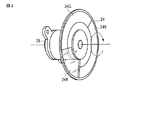
このカラーホイール24は、モータ(M)25により回転される。レーザ光が照射されるカラーホイール24の周上には、赤色蛍光反射板24R、緑色蛍光反射板24G、及び青色用拡散板24Bが合わせてリング状となるように形成されている。
The
図3は、カラーホイール24及びモータ25の外観構成を示す斜視図である。同図に示す如く、赤色蛍光反射板24Rは、レーザ光が照射されるのとは反対側の図示しない面側がミラー光像となり、青色のレーザ光の照射により塗布されている蛍光体が赤色光を励起し、励起した赤色光を、レーザ光が照射されてきた方向に反射するように出射する。
FIG. 3 is a perspective view showing the external configuration of the
同様に緑色蛍光反射板24Gは、レーザ光が照射されるのとは反対側の図示しない面側がミラー構造となり、青色のレーザ光の照射により塗布されている蛍光体が緑光を励起し、励起した緑色光を、レーザ光が照射されてきた方向に反射するように出射する。
Similarly, the green fluorescent reflecting
また、残る青色用拡散板24Bは、磨り硝子状の透過部材で構成され、照射された青色のレーザ光は散乱しながら透過する。
The remaining
カラーホイール24の赤色蛍光反射板24Rまたは緑色蛍光反射板24Gがレーザ光の照射位置にある場合、レーザ光の照射により赤色光または緑色光が励起される。この励起された赤色光または緑色光は、カラーホイール24で反射された後、上記レンズ23を介して上記ダイクロイックミラー22でも反射される。
When the red
その後、この赤色光または緑色光は、レンズ26を介してミラー27で反射され、レンズ28を介してダイクロイックミラー29で反射された後、レンズ30を介してインテグレータ31で輝度分布が略均一な光束とされた後にミラー32で全反射されて、上記ミラー18へ送られる。
Thereafter, the red light or green light is reflected by the
また、カラーホイール24の青色用拡散板24Bがレーザ光の照射位置にある場合、レーザ光は該拡散板24Bで拡散されながらカラーホイール24を透過した後、レンズ33を介してミラー34で全反射される。その後、この青色光は、レンズ35を介して上記ダイクロイックミラー29を透過し、レンズ30を介して上記インテグレータ29で輝度分布が略均一な光束とされた後にミラー32で全反射されて、上記ミラー18へ送られる。
In addition, when the
以上の如く、ダイクロイックミラー22,29は共に、青色光を透過する一方で、緑色光及び赤色光を反射する。
As described above, the
光源部17の半導体レーザ部21の発光タイミング、及びモータ25によるカラーホイール24の回転を投影光処理部36が統括して制御する。投影光処理部36は、投影画像処理部15から与えられる画像データのタイミングに応じて半導体レーザ部21の発光タイミングとカラーホイール24の回転を制御する。
The projection
上記各回路の動作すべてをCPU37が制御する。このCPU37は、メインメモリ38及びプログラムメモリ39と直接接続される。メインメモリ38は、DRAMで構成され、CPU37のワークメモリとして機能する。プログラムメモリ39は、電気的書換可能な不揮発性メモリで構成され、CPU37が実行する動作プログラムや各種定型データ等を記憶する。CPU37は、上記メインメモリ38及びプログラムメモリ39を用いて、このデータプロジェクタ装置10内の制御動作を実行する。
The
上記CPU37は、操作部40からのキー操作信号に応じて各種投影動作を実行する。
この操作部40は、データプロジェクタ装置10の本体に設けられるキー操作部と、このデータプロジェクタ装置10専用の図示しないリモートコントローラの間で赤外光を受光するレーザ受光部とを含み、ユーザが本体のキー操作部またはリモートコントローラで操作したキーに基づくキー操作信号をCPU37へ直接出力する。
The
The
上記CPU37はさらに、上記システムバスSBを介して音声処理部41とも接続される。音声処理部41は、PCM音源等の音源回路を備え、投影動作時に与えられる音声データをアナログ化し、スピーカ部42を駆動して拡声放音させ、あるいは必要によりビープ音等を発生させる。
The
次に上記実施形態の動作について説明する。
図4は、カラー画像1フレームを構成するR,G,Bの各フィールドと、半導体レーザ部21を構成するレーザダイオード21a〜21fの発光タイミングとの関係を例示するタイミングチャートである。
Next, the operation of the above embodiment will be described.
FIG. 4 is a timing chart illustrating the relationship between the R, G, and B fields that make up one frame of a color image and the light emission timings of the
図4(A)は、投影動作中のカラー画像1フレームを構成するR,G,Bの各フィールドのタイミングを示す。
1フレームの先頭となるRフィールドでは、半導体レーザ部21の出射する青色のレーザ光の光路上にカラーホイール24の赤色蛍光反射板24Rが位置する。赤色蛍光反射板24Rに塗布された蛍光体に青色のレーザ光が照射されることで、赤色光が励起する。
FIG. 4A shows the timing of each field of R, G, and B constituting one frame of a color image during the projection operation.
In the R field at the head of one frame, the
励起した赤色光は、レンズ23、ダイクロイックミラー22、レンズ26、ミラー27、及びレンズ28の経路を通ってダイクロイックミラー29で反射され、さらにレンズ30、インテグレータ31、ミラー32、及びミラー18を介してマイクロミラー素子16に照射される。
The excited red light is reflected by the
このRフィールド期間中にマイクロミラー素子16では、投影画像処理部15の駆動により赤色光に対応した階調画像を表示している。そのため、その反射光により赤色の光像が形成され、形成された赤色の光像が投影レンズユニット19により拡大されて投影対象の図示しないスクリーンに投射される。
During the R field period, the
このRフィールド期間においては、図4(B)〜図4(G)に示すように半導体レーザ部21では6個のレーザダイオード21a〜21fが全てが期間中全体に渡って発光駆動される。
In the R field period, as shown in FIGS. 4B to 4G, in the
したがって、レーザダイオード21a〜21fからのレーザ光が照射される対象が例えば金属やプラスチックの粗面など、同じ波長で拡散反射する部材の表面であればスペックルノイズが発生するところであるが、ここでは赤色蛍光反射板24Rに塗布された蛍光体にレーザ光の光エネルギーが吸収され、周波数変換される形態で代わって赤色光が励起される。そのため、スペックルノイズの発生を確実に回避できる。
Accordingly, speckle noise is generated if the object irradiated with the laser light from the
上記Rフィールドに続くGフィールドも同様であり、半導体レーザ部21の出射する青色のレーザ光の光路上にカラーホイール24の緑色蛍光反射板24Gが位置する。緑色蛍光反射板24Gに塗布された蛍光体に青色のレーザ光が照射されることで、緑色光が励起する。
The same applies to the G field following the R field, and the
励起した緑色光は、レンズ23、ダイクロイックミラー22、レンズ26、ミラー27、及びレンズ28の経路を通ってダイクロイックミラー29で反射され、さらにレンズ30、インテグレータ31、ミラー32、及びミラー18を介してマイクロミラー素子16に照射される。
The excited green light is reflected by the
このGフィールド期間中にマイクロミラー素子16では、投影画像処理部15の駆動により緑色光に対応した階調画像を表示している。そのため、その反射光により緑色の光像が形成され、形成された緑色の光像が投影レンズユニット19により拡大されて投影対象の図示しないスクリーンに投射される。
During the G field period, the
このGフィールド期間においても、図4(B)〜図4(G)に示すように半導体レーザ部21では6個のレーザダイオード21a〜21fが全てが期間中全体に渡って発光駆動される。
Also during the G field period, as shown in FIGS. 4B to 4G, in the
したがって、緑色蛍光反射板24Gに塗布された蛍光体にレーザ光の光エネルギーが吸収され、周波数変換される形態で代わって緑色光が励起されるため、スペックルノイズの発生を確実に回避できる。
Accordingly, the light energy of the laser light is absorbed by the phosphor applied to the
その後のBフィールドでは、半導体レーザ部21の出射する青色のレーザ光の光路上にカラーホイール24の青色用拡散板24Bが位置する。そのため、青色のレーザ光は波長を代えることなく青色用拡散板24Bを拡散しながら透過する。
In the subsequent B field, the
青色用拡散板24Bを透過した青色光は、レンズ33、ミラー34、及びレンズ35の経路を通ってダイクロイックミラー29を透過し、さらにレンズ30、インテグレータ31、ミラー32、及びミラー18を介してマイクロミラー素子16に照射される。
The blue light transmitted through the
このBフィールド期間中にマイクロミラー素子16では、投影画像処理部15の駆動により青色光に対応した階調画像を表示している。そのため、その反射光により青色の光像が形成され、形成された青色の光像が投影レンズユニット19により拡大されて投影対象の図示しないスクリーンに投射される。
During the B field period, the
このBフィールド期間にあっては、図4(B)〜図4(G)に示すように半導体レーザ部21では6個のレーザダイオード21a〜21fのうち、常に4個が発光し、残る2個が発光を停止するように順次発光位置を短い時間単位で切換えながら循環的に間欠駆動する。
In the B field period, as shown in FIGS. 4B to 4G, the
具体的には、レーザダイオード21aと21d、レーザダイオード21bと21e、レーザダイオード21cと21fをそれぞれ組として、点灯を停止する組を循環的に切り換えることで、このBフィールド期間中には6個中4個のレーザダイオードによる間欠的な発光駆動を行なうものとする。
Specifically, the
このようにBフィールド期間内の短い周期でレーザダイオード21a〜21fの発光位置を切り換えることにより、たとえ青色用拡散板24B部分でのレーザ光の拡散によりスペックルノイズが発生したとしても、その発生位置が非常に短い時間単位で移動するため、人間の肉眼では全く知覚できない。
Thus, even if speckle noise occurs due to the diffusion of the laser light in the
したがって、結果として人間の肉眼で知覚することが可能なスペックルノイズの発生を確実に回避できる。 As a result, it is possible to reliably avoid the generation of speckle noise that can be perceived by the human naked eye.
なお、上記画像1フレームにおけるR,G,B各フィールドの時間比は、モータ25により定速で回転駆動されるカラーホイール24の赤色蛍光反射板24R、緑色蛍光反射板24G、及び青色用拡散板24Bの中心角によって決定される。
The time ratio of each field of R, G, and B in one frame of the image is such that the
本実施形態では、上記図4(A)で示したようにR>G>Bの順序でより時間が長くなるように設定した例を示したが、これは光源を構成するレーザダイオード21a〜21fの発光強度と発振周波数、赤色蛍光反射板24R及び緑色蛍光反射板24Gに塗布された各蛍光体の蛍光特性等に鑑みて適宜設定される。
In the present embodiment, as shown in FIG. 4A, an example in which the time is set to be longer in the order of R> G> B is shown, but this is the case of the
以上詳記した如く本実施形態によれば、複雑な構成を採ることなく、半導体レーザ部21を構成するレーザダイオード21a〜21fの間欠駆動によりスペックルノイズの発生を確実に抑制することが可能となる。
As described in detail above, according to the present embodiment, it is possible to reliably suppress generation of speckle noise by intermittent driving of the
また、上記実施形態では、半導体レーザ部21を複数、例えば6個のレーザダイオード21a〜21fで構成するものとして説明したが、このように同一波長で発振する複数のレーザ光源を用いて、短い時間間隔で発光位置を順次切換ながら間欠駆動することで、より確実にスペックルノイズの発生を抑制することが可能となる。
Further, in the above-described embodiment, the
なお、本発明はレーザ光源を構成する素子の個数やそれらのうちで一時的に発光を停止する個数を限定するものではない。 Note that the present invention does not limit the number of elements constituting the laser light source and the number of them that temporarily stop light emission.
また、光源に1つのレーザ光源のみを用いるものとし、スペックルノイズの発生が予想される期間においてはその1つのレーザダイオードを間欠的に駆動させるものとしても良く、カラーホイール24の青色用拡散板24Bがレーザ光に対して相対的に移動(回転)していることを勘案しても、知覚可能なレベルでのスペックルノイズの発生を充分に抑制することが可能となる。 Further, only one laser light source may be used as the light source, and the one laser diode may be intermittently driven during the period when speckle noise is expected to occur. Even taking into account that 24B moves (rotates) relative to the laser beam, it is possible to sufficiently suppress the generation of speckle noise at a perceptible level.
さらに、上記実施形態は本発明を単板式のDLP(登録商標)方式のデータプロジェクタ装置10に適用した場合について説明したが、本発明はデータプロジェクタ装置の投影方式を限定するものではなく、例えば透過型のモノクロ液晶パネルを用いて光像を形成する液晶プロジェクタ装置にも同様に適用可能であり、またデータプロジェクタ装置のみならず、例えばリアプロジェクション方式のテレビ受像機等にも同様に適用し得る。
Furthermore, although the above embodiment has been described with respect to the case where the present invention is applied to the single-plate DLP (registered trademark)
その他、本発明は上述した実施形態に限定されるものではなく、実施段階ではその要旨を逸脱しない範囲で種々に変形することが可能である。また、上述した実施形態で実行される機能は可能な限り適宜組み合わせて実施しても良い。上述した実施形態には種々の段階が含まれており、開示される複数の構成要件による適宜の組み合せにより種々の発明が抽出され得る。例えば、実施形態に示される全構成要件からいくつかの構成要件が削除されても、効果が得られるのであれば、この構成要件が削除された構成が発明として抽出され得る。 In addition, the present invention is not limited to the above-described embodiments, and various modifications can be made without departing from the scope of the invention in the implementation stage. Further, the functions executed in the above-described embodiments may be combined as appropriate as possible. The above-described embodiment includes various stages, and various inventions can be extracted by an appropriate combination of a plurality of disclosed constituent elements. For example, even if some constituent requirements are deleted from all the constituent requirements shown in the embodiment, if the effect is obtained, a configuration from which the constituent requirements are deleted can be extracted as an invention.
10…データプロジェクタ装置、11…入出力コネクタ部、12…入出力インタフェース(I/F)、13…画像変換部(スケーラ)、14…ビデオRAM、15…投影画像処理部、16…マイクロミラー素子(SLM)、17…光源部、18…ミラー、19…投影レンズユニット、21…半導体レーザ部(LDU)、21a〜21f…レーザダイオード、22…ダイクロイックミラー、23…レンズ、24…カラーホイール、24B…青色用拡散板、24G…緑色蛍光体反射板、25…モータ(M)、26…レンズ、27…ミラー、28…レンズ、29…ダイクロイックミラー、30…レンズ、31…インテグレータ、32…ミラー、33…レンズ、34…ミラー、35…レンズ、36…投影光処理部、37…CPU、38…メインメモリ、39…プログラムメモリ、40…操作部、41…音声処理部、42…スピーカ部、SB…システムバス。
DESCRIPTION OF
Claims (7)
上記レーザ光の波長を変化させずに出射する期間と、上記レーザ光の波長を変換して出射する期間と、を周期的に繰返す波長変換手段と、
上記波長変換手段で上記レーザ光の波長を変化させずに出射する期間中、上記光源を間欠駆動する光源制御手段と
を具備したことを特徴とする光源装置。 A light source that generates laser light;
Wavelength converting means for periodically repeating a period of emitting without changing the wavelength of the laser light, and a period of converting and emitting the wavelength of the laser light;
A light source device comprising: a light source control means for intermittently driving the light source during a period in which the wavelength conversion means emits the laser light without changing its wavelength.
上記光源制御手段は、上記波長変換手段で上記レーザ光の波長を変化させずに出射する期間中、上記複数のレーザ発光素子の発光位置を切り換えながら上記複数のレーザ発光素子を循環的に間欠駆動する
ことを特徴とする請求項1記載の光源装置。 The light source has a plurality of laser light emitting elements,
The light source control means cyclically intermittently drives the plurality of laser light emitting elements while switching the light emission positions of the plurality of laser light emitting elements during the period in which the wavelength conversion means emits the laser light without changing the wavelength. The light source device according to claim 1 .
上記レーザ光の波長を変化させずに出射する期間と、上記レーザ光の波長を変換して出射する期間と、を周期的に繰返す波長変換手段と、
上記波長変換手段で上記レーザ光の波長を変化させずに出射する期間中、上記光源を間欠駆動する光源制御手段と、
画像信号を入力する入力手段と、
上記波長変換手段から出射する光を用い、上記入力手段で入力する画像信号に対応したカラーの光像を形成して投影する投影手段と
を具備したことを特徴とする投影装置。 A light source that generates laser light;
Wavelength converting means for periodically repeating a period of emitting without changing the wavelength of the laser light, and a period of converting and emitting the wavelength of the laser light;
A light source control means for intermittently driving the light source during a period of emission without changing the wavelength of the laser light by the wavelength conversion means;
An input means for inputting an image signal;
A projection apparatus comprising: projection means for forming and projecting a color light image corresponding to an image signal input by the input means using light emitted from the wavelength conversion means.
上記光源制御手段は、上記波長変換手段で上記レーザ光の波長を変化させずに出射する期間中、上記複数のレーザ発光素子の発光位置を切り換えながら上記複数のレーザ発光素子を循環的に間欠駆動する
ことを特徴とする請求項3記載の投影装置。 The light source has a plurality of laser light emitting elements,
The light source control means cyclically intermittently drives the plurality of laser light emitting elements while switching the light emission positions of the plurality of laser light emitting elements during the period in which the wavelength conversion means emits the laser light without changing the wavelength. The projection apparatus according to claim 3, wherein:
上記波長変換部で上記レーザ光の波長を変化させずに出射する期間中、上記光源を間欠駆動する光源制御工程を有したことを特徴とする投影方法。 A light source that generates laser light, a wavelength conversion unit that periodically repeats a period of emission without changing the wavelength of the laser light, and a period of emission after converting the wavelength of the laser light, and an image signal are input A projection method in a projection apparatus including a projection unit that forms and projects a color light image corresponding to an image signal input by the input unit using light emitted from the input unit and the wavelength conversion unit. ,
A projection method comprising: a light source control step of intermittently driving the light source during a period in which the wavelength conversion unit emits the laser light without changing the wavelength.
Priority Applications (1)
| Application Number | Priority Date | Filing Date | Title |
|---|---|---|---|
| JP2009225015A JP5428710B2 (en) | 2009-09-29 | 2009-09-29 | Light source device, projection device, and projection method |
Applications Claiming Priority (1)
| Application Number | Priority Date | Filing Date | Title |
|---|---|---|---|
| JP2009225015A JP5428710B2 (en) | 2009-09-29 | 2009-09-29 | Light source device, projection device, and projection method |
Publications (3)
| Publication Number | Publication Date |
|---|---|
| JP2011075673A JP2011075673A (en) | 2011-04-14 |
| JP2011075673A5 JP2011075673A5 (en) | 2012-11-15 |
| JP5428710B2 true JP5428710B2 (en) | 2014-02-26 |
Family
ID=44019751
Family Applications (1)
| Application Number | Title | Priority Date | Filing Date |
|---|---|---|---|
| JP2009225015A Active JP5428710B2 (en) | 2009-09-29 | 2009-09-29 | Light source device, projection device, and projection method |
Country Status (1)
| Country | Link |
|---|---|
| JP (1) | JP5428710B2 (en) |
Cited By (2)
| Publication number | Priority date | Publication date | Assignee | Title |
|---|---|---|---|---|
| WO2018094696A1 (en) * | 2016-11-25 | 2018-05-31 | 深圳迈瑞生物医疗电子股份有限公司 | Endoscope system, and light source device thereof |
| WO2018094695A1 (en) * | 2016-11-25 | 2018-05-31 | 深圳迈瑞生物医疗电子股份有限公司 | Endoscope system and control method therefor |
Families Citing this family (4)
| Publication number | Priority date | Publication date | Assignee | Title |
|---|---|---|---|---|
| JP5757176B2 (en) * | 2011-06-30 | 2015-07-29 | セイコーエプソン株式会社 | Light source device and projector |
| US9435996B2 (en) | 2012-12-07 | 2016-09-06 | Samsung Electronics Co., Ltd. | Illumination optical system for beam projector |
| TWI540377B (en) | 2014-01-29 | 2016-07-01 | 台達電子工業股份有限公司 | Optical wavelength converter and illumination system using same |
| JP6642817B2 (en) * | 2015-09-18 | 2020-02-12 | カシオ計算機株式会社 | Light source device and projection device |
Family Cites Families (12)
| Publication number | Priority date | Publication date | Assignee | Title |
|---|---|---|---|---|
| AU2003208566A1 (en) * | 2003-01-08 | 2004-08-10 | Explay Ltd. | An image projecting device and method |
| JP4604458B2 (en) * | 2003-04-25 | 2011-01-05 | セイコーエプソン株式会社 | Projection display |
| JP4829470B2 (en) * | 2003-05-14 | 2011-12-07 | Necディスプレイソリューションズ株式会社 | Projection display |
| JP2004354717A (en) * | 2003-05-29 | 2004-12-16 | Seiko Epson Corp | Display device and projection display device |
| JP2006301114A (en) * | 2005-04-18 | 2006-11-02 | Sony Corp | Illumination device and picture display device |
| JP2007218956A (en) * | 2006-02-14 | 2007-08-30 | Sharp Corp | Projection type image display apparatus |
| JP5451382B2 (en) * | 2006-06-02 | 2014-03-26 | コーニンクレッカ フィリップス エヌ ヴェ | Illumination device for generating colored and white light |
| JP2008052070A (en) * | 2006-08-25 | 2008-03-06 | Samsung Electronics Co Ltd | Color wheel, visible light source, and projection image display device and method |
| US7630419B2 (en) * | 2007-01-10 | 2009-12-08 | Seiko Epson Corporation | Laser light source device, and image device using the same |
| JP5194973B2 (en) * | 2007-04-10 | 2013-05-08 | セイコーエプソン株式会社 | Light source device, monitor device, projector, and driving method of light source device |
| JP2009133926A (en) * | 2007-11-28 | 2009-06-18 | Kyocera Corp | Optical projector |
| US8351108B2 (en) * | 2009-08-03 | 2013-01-08 | Panasonic Corporation | Wavelength conversion laser and image display device |
-
2009
- 2009-09-29 JP JP2009225015A patent/JP5428710B2/en active Active
Cited By (2)
| Publication number | Priority date | Publication date | Assignee | Title |
|---|---|---|---|---|
| WO2018094696A1 (en) * | 2016-11-25 | 2018-05-31 | 深圳迈瑞生物医疗电子股份有限公司 | Endoscope system, and light source device thereof |
| WO2018094695A1 (en) * | 2016-11-25 | 2018-05-31 | 深圳迈瑞生物医疗电子股份有限公司 | Endoscope system and control method therefor |
Also Published As
| Publication number | Publication date |
|---|---|
| JP2011075673A (en) | 2011-04-14 |
Similar Documents
| Publication | Publication Date | Title |
|---|---|---|
| TWI499857B (en) | Light source device, projecting device and projecting method | |
| JP5796272B2 (en) | Light source device, projection device, and projection method | |
| JP5412996B2 (en) | Light source device, projection device, and projection method | |
| JP4900428B2 (en) | Projection apparatus and projection method | |
| JP4924677B2 (en) | Light source device, projection device, and projection method | |
| JP5585475B2 (en) | Projection device | |
| JP5223941B2 (en) | Projection device | |
| JP5272842B2 (en) | Light source device and projection device | |
| JP5494610B2 (en) | Projection apparatus, projection control method, and program | |
| JP5428710B2 (en) | Light source device, projection device, and projection method | |
| JP5671806B2 (en) | Projection apparatus and projection method | |
| JP5625675B2 (en) | Projection apparatus, projection method, and program | |
| JP5640761B2 (en) | Projection apparatus, projection method, and program | |
| JP2012128438A (en) | Light source device, projection device, and projection method | |
| JP5915317B2 (en) | Light source device, projector device, and light source driving method | |
| JP5445575B2 (en) | Projection apparatus and projection method | |
| JP5668286B2 (en) | Projection apparatus, projection method, and program | |
| JP5454061B2 (en) | Light source device, projection device, projection method and program | |
| JP2013195797A (en) | Light source device, projector and light source control method | |
| JP2023044143A (en) | Image projection device, image projection method, and program | |
| JP2014160247A (en) | Projection device, projection control method, and program |
Legal Events
| Date | Code | Title | Description |
|---|---|---|---|
| A521 | Written amendment |
Free format text: JAPANESE INTERMEDIATE CODE: A523 Effective date: 20120927 |
|
| A621 | Written request for application examination |
Free format text: JAPANESE INTERMEDIATE CODE: A621 Effective date: 20120927 |
|
| A977 | Report on retrieval |
Free format text: JAPANESE INTERMEDIATE CODE: A971007 Effective date: 20130716 |
|
| A131 | Notification of reasons for refusal |
Free format text: JAPANESE INTERMEDIATE CODE: A131 Effective date: 20130723 |
|
| A521 | Written amendment |
Free format text: JAPANESE INTERMEDIATE CODE: A523 Effective date: 20130913 |
|
| TRDD | Decision of grant or rejection written | ||
| A01 | Written decision to grant a patent or to grant a registration (utility model) |
Free format text: JAPANESE INTERMEDIATE CODE: A01 Effective date: 20131105 |
|
| A61 | First payment of annual fees (during grant procedure) |
Free format text: JAPANESE INTERMEDIATE CODE: A61 Effective date: 20131118 |
|
| R150 | Certificate of patent or registration of utility model |
Free format text: JAPANESE INTERMEDIATE CODE: R150 Ref document number: 5428710 Country of ref document: JP Free format text: JAPANESE INTERMEDIATE CODE: R150 |