JP7098483B2 - Light source device and image projection device - Google Patents
Light source device and image projection device Download PDFInfo
- Publication number
- JP7098483B2 JP7098483B2 JP2018162674A JP2018162674A JP7098483B2 JP 7098483 B2 JP7098483 B2 JP 7098483B2 JP 2018162674 A JP2018162674 A JP 2018162674A JP 2018162674 A JP2018162674 A JP 2018162674A JP 7098483 B2 JP7098483 B2 JP 7098483B2
- Authority
- JP
- Japan
- Prior art keywords
- light source
- light
- lighting
- drive current
- light sources
- Prior art date
- Legal status (The legal status is an assumption and is not a legal conclusion. Google has not performed a legal analysis and makes no representation as to the accuracy of the status listed.)
- Active
Links
Images


Classifications
-
- G—PHYSICS
- G03—PHOTOGRAPHY; CINEMATOGRAPHY; ANALOGOUS TECHNIQUES USING WAVES OTHER THAN OPTICAL WAVES; ELECTROGRAPHY; HOLOGRAPHY
- G03B—APPARATUS OR ARRANGEMENTS FOR TAKING PHOTOGRAPHS OR FOR PROJECTING OR VIEWING THEM; APPARATUS OR ARRANGEMENTS EMPLOYING ANALOGOUS TECHNIQUES USING WAVES OTHER THAN OPTICAL WAVES; ACCESSORIES THEREFOR
- G03B21/00—Projectors or projection-type viewers; Accessories therefor
- G03B21/14—Details
- G03B21/20—Lamp housings
- G03B21/2053—Intensity control of illuminating light
-
- G—PHYSICS
- G03—PHOTOGRAPHY; CINEMATOGRAPHY; ANALOGOUS TECHNIQUES USING WAVES OTHER THAN OPTICAL WAVES; ELECTROGRAPHY; HOLOGRAPHY
- G03B—APPARATUS OR ARRANGEMENTS FOR TAKING PHOTOGRAPHS OR FOR PROJECTING OR VIEWING THEM; APPARATUS OR ARRANGEMENTS EMPLOYING ANALOGOUS TECHNIQUES USING WAVES OTHER THAN OPTICAL WAVES; ACCESSORIES THEREFOR
- G03B21/00—Projectors or projection-type viewers; Accessories therefor
- G03B21/14—Details
- G03B21/16—Cooling; Preventing overheating
-
- G—PHYSICS
- G03—PHOTOGRAPHY; CINEMATOGRAPHY; ANALOGOUS TECHNIQUES USING WAVES OTHER THAN OPTICAL WAVES; ELECTROGRAPHY; HOLOGRAPHY
- G03B—APPARATUS OR ARRANGEMENTS FOR TAKING PHOTOGRAPHS OR FOR PROJECTING OR VIEWING THEM; APPARATUS OR ARRANGEMENTS EMPLOYING ANALOGOUS TECHNIQUES USING WAVES OTHER THAN OPTICAL WAVES; ACCESSORIES THEREFOR
- G03B21/00—Projectors or projection-type viewers; Accessories therefor
- G03B21/14—Details
- G03B21/20—Lamp housings
- G03B21/2006—Lamp housings characterised by the light source
- G03B21/2013—Plural light sources
-
- G—PHYSICS
- G03—PHOTOGRAPHY; CINEMATOGRAPHY; ANALOGOUS TECHNIQUES USING WAVES OTHER THAN OPTICAL WAVES; ELECTROGRAPHY; HOLOGRAPHY
- G03B—APPARATUS OR ARRANGEMENTS FOR TAKING PHOTOGRAPHS OR FOR PROJECTING OR VIEWING THEM; APPARATUS OR ARRANGEMENTS EMPLOYING ANALOGOUS TECHNIQUES USING WAVES OTHER THAN OPTICAL WAVES; ACCESSORIES THEREFOR
- G03B21/00—Projectors or projection-type viewers; Accessories therefor
- G03B21/14—Details
- G03B21/20—Lamp housings
- G03B21/2006—Lamp housings characterised by the light source
- G03B21/2033—LED or laser light sources
- G03B21/204—LED or laser light sources using secondary light emission, e.g. luminescence or fluorescence
-
- G—PHYSICS
- G03—PHOTOGRAPHY; CINEMATOGRAPHY; ANALOGOUS TECHNIQUES USING WAVES OTHER THAN OPTICAL WAVES; ELECTROGRAPHY; HOLOGRAPHY
- G03B—APPARATUS OR ARRANGEMENTS FOR TAKING PHOTOGRAPHS OR FOR PROJECTING OR VIEWING THEM; APPARATUS OR ARRANGEMENTS EMPLOYING ANALOGOUS TECHNIQUES USING WAVES OTHER THAN OPTICAL WAVES; ACCESSORIES THEREFOR
- G03B21/00—Projectors or projection-type viewers; Accessories therefor
- G03B21/005—Projectors using an electronic spatial light modulator but not peculiar thereto
- G03B21/006—Projectors using an electronic spatial light modulator but not peculiar thereto using LCD's
-
- G—PHYSICS
- G03—PHOTOGRAPHY; CINEMATOGRAPHY; ANALOGOUS TECHNIQUES USING WAVES OTHER THAN OPTICAL WAVES; ELECTROGRAPHY; HOLOGRAPHY
- G03B—APPARATUS OR ARRANGEMENTS FOR TAKING PHOTOGRAPHS OR FOR PROJECTING OR VIEWING THEM; APPARATUS OR ARRANGEMENTS EMPLOYING ANALOGOUS TECHNIQUES USING WAVES OTHER THAN OPTICAL WAVES; ACCESSORIES THEREFOR
- G03B21/00—Projectors or projection-type viewers; Accessories therefor
- G03B21/14—Details
- G03B21/20—Lamp housings
- G03B21/2073—Polarisers in the lamp house
Description
本発明は、液晶プロジェクタ等の画像投射装置に好適な光源装置に関する。 The present invention relates to a light source device suitable for an image projection device such as a liquid crystal projector.
光源から発せられた光を、液晶パネル等の光変調素子により画像変調してスクリーン等の被投射面に投射する画像投射装置(以下、プロジェクタという)には、光源としてレーザダイオード(LD)を用いるものがある。このようなプロジェクタには、特許文献1にて開示されているように、互いに異なる波長の光を発する複数のLD(青色LDと赤色LD)を用いるものがある。 A laser diode (LD) is used as a light source for an image projection device (hereinafter referred to as a projector) that image-modulates light emitted from a light source by a light modulation element such as a liquid crystal panel and projects it onto a projected surface such as a screen. There is something. As disclosed in Patent Document 1, such a projector may use a plurality of LDs (blue LD and red LD) that emit light having different wavelengths from each other.
ただし、赤色LDには、青色LDに比べて、特に温度が低いときに光学損傷(COD:Catastrophic Optical Damage)を引き起こしやすいという性質がある。特許文献2には、CODの発生を抑制するための方法が開示されている。
However, the red LD has a property that it is more likely to cause optical damage (COD: Catastrophic Optical Damage) than the blue LD, especially when the temperature is low.
しかしながら、特許文献2に開示された方法では、LDに供給する駆動電流を制御するため、LDの点灯が完了するまでに時間がかかり、その結果、プロジェクタの起動時間が長くなる。
However, in the method disclosed in
本発明は、赤色LD等の光源におけるCODの発生を抑制しつつ、起動時間を短くすることができるようにした光源装置および画像投射装置を提供する。 The present invention provides a light source device and an image projection device capable of shortening the start-up time while suppressing the generation of COD in a light source such as a red LD.
本発明の一側面としての光源装置は、第1の光源と、第1の光源からの入射光とは波長が異なる変換光を生成する波長変換素子と、波長変換素子を回転させるモータと、該第1の光源とは異なる波長の光を発する第2の光源と、第1および第2の光源を制御する制御手段とを有する。制御手段は、第2の光源の駆動電流における、点灯開始から所定の点灯状態に増加するまでの時間を、第1の光源の駆動電流における、点灯開始から所定の点灯状態に増加するまでの時間よりも長い時間をかけて制御し、第2の光源の点灯開始を、第1の光源の点灯開始よりも早く制御し、第2の光源の点灯開始を、モータの回転開始の前に開始し、第1の光源の点灯開始を、モータの回転開始の後に開始することを特徴とする。 The light source device as one aspect of the present invention includes a first light source , a wavelength conversion element that generates conversion light having a wavelength different from that of incident light from the first light source, a motor that rotates the wavelength conversion element, and the like. It has a second light source that emits light having a wavelength different from that of the first light source, and control means for controlling the first and second light sources. The control means measures the time from the start of lighting to the increase in the predetermined lighting state in the drive current of the second light source , and the time from the start of lighting to the increase in the predetermined lighting state in the drive current of the first light source. Control over a longer period of time, controlling the start of lighting of the second light source earlier than the start of lighting of the first light source, and starting the lighting of the second light source before the start of rotation of the motor. The lighting of the first light source is started after the rotation of the motor is started .
なお、上記光源装置と、該光源装置からの光を変調する光変調部とを有し、光変調部からの光により形成される画像を被投射面に投射する画像投射装置も、本発明の他の一側面を構成する。 An image projection device having the above-mentioned light source device and a light modulation unit that modulates the light from the light source device and projecting an image formed by the light from the light modulation unit onto a projected surface is also described in the present invention. Consists of another aspect.
また、本発明の他の一側面としての制御方法は、第1の光源と、該第1の光源とは異なる波長の光を発する第2の光源と、第1の光源からの入射光とは波長が異なる変換光を生成する波長変換素子と、波長変換素子を回転させるモータとを有する光源装置に適用される。該制御方法は、第2の光源の点灯開始を、モータの回転開始および第1の光源の点灯開始よりも先に開始するステップと、第2の光源を、点灯開始から所定の点灯状態までの時間を、第1の光源の点灯開始から所定の点灯状態までの時間よりも長い時間をかけて制御するステップと、第1の光源の点灯開始を、モータの回転開始よりも後に開始するステップとを有することを特徴とする。 Further, in the control method as another aspect of the present invention, the first light source, the second light source that emits light having a wavelength different from that of the first light source, and the incident light from the first light source are different from each other. It is applied to a light source device having a wavelength conversion element that generates converted light having different wavelengths and a motor that rotates the wavelength conversion element . The control method includes a step of starting the lighting of the second light source before the start of rotation of the motor and the start of lighting of the first light source, and the second light source from the start of lighting to a predetermined lighting state . A step of controlling the time over a time longer than the time from the start of lighting of the first light source to a predetermined lighting state, and a step of starting the start of lighting of the first light source after the start of rotation of the motor. It is characterized by having.
なお、光源装置のコンピュータに、上記制御方法に従う処理を実行させるコンピュータプログラムも、本発明の他の一側面を構成する。 A computer program that causes the computer of the light source device to execute a process according to the above control method also constitutes another aspect of the present invention.
本発明によれば、第2の光源におけるCODの発生を抑制しつつ、第1および第2の光源の点灯が完了するまでの起動時間を短くすることができる。 According to the present invention, it is possible to shorten the start-up time until the lighting of the first and second light sources is completed while suppressing the generation of COD in the second light source.
以下、本発明の実施例について図面を参照しながら説明する。 Hereinafter, examples of the present invention will be described with reference to the drawings.
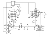
図1は、本発明の実施例1である画像投射装置としてのプロジェクタの構成を示している。以下の説明において、R、G、Bはそれぞれ、赤、緑、青の意味である。1はシステム制御部、2は駆動電流算出部、3は光源駆動部である。4ba,4bbはB光源であり、4rc,4rdはR光源である。5bはB光源用ヒートシンク、5rはR光源用ヒートシンク、6bはB光源用冷却部、6rはR光源用冷却部、7は冷却制御部である。 FIG. 1 shows a configuration of a projector as an image projection device according to a first embodiment of the present invention. In the following description, R, G, and B mean red, green, and blue, respectively. 1 is a system control unit, 2 is a drive current calculation unit, and 3 is a light source drive unit. 4ba and 4bb are B light sources, and 4rc and 4rd are R light sources. 5b is a heat sink for a B light source, 5r is a heat sink for an R light source, 6b is a cooling unit for a B light source, 6r is a cooling unit for an R light source, and 7 is a cooling control unit.
8ba,8bbはB用コリメートレンズであり、8rc,8rdはR用コリメートレンズである。9は第1のレンズ、10は第2のレンズ、12は光反射部材、13はガラス板、14は第3のレンズである。15は蛍光体、16は蛍光体支持部材、17はモータ、18はモータ制御部である。20aは第1のフライアイレンズ、20bは第2のフライアイレンズ、21は偏光変換素子、22は第4のレンズである。
8ba and 8bb are collimating lenses for B, and 8rc and 8rd are collimating lenses for R. 9 is a first lens, 10 is a second lens, 12 is a light reflecting member, 13 is a glass plate, and 14 is a third lens.
23はダイクロイックミラー、24は波長選択性位相板、25RBはRB用偏光ビームスプリッタ、25GはG用偏光ビームスプリッタ、26RはR用λ/4板、26GはG用λ/4板、26BはB用λ/4板である。27RはR用光変調部、27GはG用光変調部、27BはB用光変調部である。29は色合成プリズム、31は投射レンズである。 23 is a dichroic mirror, 24 is a wavelength selectivity phase plate, 25RB is a polarization beam splitter for RB, 25G is a polarization beam splitter for G, 26R is a λ / 4 plate for R, 26G is a λ / 4 plate for G, and 26B is B. Λ / 4 plate. 27R is an optical modulation unit for R, 27G is an optical modulation unit for G, and 27B is an optical modulation unit for B. 29 is a color synthesis prism, and 31 is a projection lens.
駆動電流算出部2は、システム制御部1からの指示に応じてB光源4ba,4bbおよびR光源4rc,4rdの駆動電流を算出する。光源駆動部3は、駆動電流算出部2により算出された各駆動電流を各光源に供給してこれを駆動する。
The drive
B光源(第1の光源)4ba,4bbは、B光(青光)を発する互いに同じ半導体レーザダイオードを用いて構成されている。B光源4ba,4bbのピーク波長は455nmである。R光源(第2の光源)4rc,4rdは、B光とは異なる波長のR光(赤光)を発する互いに同じ半導体レーザダイオードを用いて構成されている。R光源4rc,4rdのピーク波長は635nmである。B光源4ba,4bbは、B光源用ヒートシンク5bに取り付けられている。R光源4rc,4rdは、R光源用ヒートシンク5rに取り付けられている。各ヒートシンクとしては、放熱フィンが設けられた銅板等が用いられる。各光源と各ヒートシンクは、熱伝導シート等の伝熱部材で密着されていることが好ましい。なお、B光源およびR光源のそれぞれの数は、2つでなくてもよい。
The B light source (first light source) 4ba and 4bb are configured by using the same semiconductor laser diodes that emit B light (blue light). The peak wavelengths of the B light sources 4ba and 4bb are 455 nm. The R light sources (second light source) 4rc and 4rd are configured by using the same semiconductor laser diodes that emit R light (red light) having a wavelength different from that of B light. The peak wavelength of the R light sources 4rc and 4rd is 635 nm. The B light sources 4ba and 4bb are attached to the B light
B光源用ヒートシンク5bとR光源用ヒートシンク5rの背面にはそれぞれ、冷却手段として、冷却ファンにより構成されるB光源用冷却部(以下、B光源用冷却ファンという)6bとR光源用冷却部(以下、R光源用冷却ファンという)6rが配置されている。
On the back surface of the
B光源用冷却ファン6bおよびR光源用冷却ファン6rのそれぞれからの冷却風によってB光源用ヒートシンク5bおよびR光源用ヒートシンク5rが冷却される。B光源用冷却ファン6bとR光源用冷却ファン6rの回転数(ファン回転数)は、システム制御部1の指示に基づいて冷却制御部7によって制御される。各冷却ファンの駆動電圧を上げるとファン回転数が増加し、駆動電圧を下げるとファン回転数が減少する。図1においてB光源用冷却ファン6bとR光源用冷却ファン6rから出ている矢印の向きは、冷却風の向きを示している。
The cooling air from each of the
B光源用ヒートシンク5bおよびR光源用ヒートシンク5rはそれぞれ、B光源4ba,4bbが発した熱およびR光源4rc,4rdが発した熱を平均化する。B光源用ヒートシンク5bおよびR光源用ヒートシンク5rをそれぞれB光源用冷却ファン6bおよびR光源用冷却ファン6rにより冷却することで、B光源4ba,4bbおよびR光源4rc,4rdを同時に冷却することができる。
The
B光源4ba,4bbから発せられたB光はそれぞれ、B用コリメートレンズ8ba,8bbに入射する。R光源4rc,4rdから発せられたR光はそれぞれ、R用コリメートレンズ8rc,8rdに入射する。各コリメートレンズは、各光源からの光を略平行光に変換する。図1における各光源からの矢印の向きは、光の光路と進行方向を表している。このことは以降の光路おいても同様である。 The B light emitted from the B light sources 4ba and 4bb is incident on the collimating lenses 8ba and 8bb for B, respectively. The R light emitted from the R light sources 4rc and 4rd is incident on the R collimating lenses 8rc and 8rd, respectively. Each collimating lens converts the light from each light source into substantially parallel light. The direction of the arrow from each light source in FIG. 1 represents the optical path and the traveling direction of the light. This also applies to the subsequent optical paths.
各コリメートレンズから出射した光は、第1のレンズ9および第2のレンズ10に入射して励起光11として出射する。第1のレンズ9と第2のレンズ10は、各コリメートレンズから出射した光の光束径を調整する役割を有する。
The light emitted from each collimating lens is incident on the first lens 9 and the
励起光11は、ガラス板13の表面に設けられた光反射部材12で反射され、第3のレンズ14を介して蛍光体(波長変換素子)15に照射される。光反射部材12は、ガラス板13の表面のうち励起光11が照射される部分にのみ設けられている。また、第3のレンズ14は、励起光11を集光して蛍光体15上に所定サイズの光照射領域を形成する。
The
蛍光体15の材料は、例えばYAG:Ceである。蛍光体15は、モータ17の回転軸を中心とした円周方向に設けられ、蛍光体支持部材16によって支持されている。蛍光体支持部材16の材料は、典型的にはアルミ等の金属板である。ただし、金属板と同様な機能を有するものであれば、金属板に限られない。モータ17は、蛍光体15からの放熱を効率的に行うために、蛍光体15および蛍光体支持部材16を回転させる。モータ17の回転数は、システム制御部1の指示に応じてモータ制御部18により制御される。
The material of the
蛍光体15は、励起光11のうちB光の一部を波長変換して黄色の蛍光光を発生させる。蛍光光と蛍光体15により波長変換されなかったBの励起光(非変換光)とR光とが合成されて白色(W)光としての照明光19が生成される。
The
照明光19は、第3のレンズ14に入射して略平行光に変換される。第3のレンズ14を透過した照明光19は、さらにガラス板13のうち光反射部材12以外の部分を透過して、第1のフライアイレンズ20aおよび第2のフライアイレンズ20bを透過することで複数の光束に分割されて偏光変換素子21に入射する。偏光変換素子21は、無偏光光である照明光19を特定の1つの偏光方向を有する直線偏光に変換する。一般に、LDからの光束は直線偏光光であるが、蛍光体15からの照明光19は無偏光光になっている。このため、後述する偏光ビームスプリッタでの偏光分離を効率良く行うために、偏光変換素子21を設けることで直線偏光(図1の紙面に垂直な偏光方向を有するS偏光)に変換する。
The
偏光変換素子21から出射した照明光19としての複数の光束は、第4のレンズ22により集光されて3つの光変調部27R,27G,27B上にて重ね合わせられる。これにより、各光変調部は均一に照明される。
The plurality of luminous fluxes as the
第4のレンズ22を透過した照明光19は、ダイクロイックミラー23に導かれる。ダイクロイックミラー23は、照明光19のうちRB光19RBを反射し、G光19Gを透過させる。ダイクロイックミラー23を透過したS偏光のG光19Gは、G用偏光ビームスプリッタ25Gに入射してその偏光分離面で反射され、G用光変調部27Gに到達する。ここで、G用光変調部27Gは、デジタル駆動式の反射型液晶表示素子であり、G光19Gを変調するための原画を形成する。システム制御部1は、外部からの入力映像信号に応じてG用光変調部27Gに原画を形成させるようにこれを駆動する。この際、システム制御部1は、G用光変調部27Gの各画素を各フレーム期間内にON/OFF駆動し、該ON/OFF駆動のデューティを制御することによりG用光変調部27Gに複数の階調を表現させる。これらのことは、R用光変調部27RとB用光変調部27Bも同様である。
The
G用光変調部27Gは、G光19Gを原画に応じて変調するとともに反射する。これにより、G用光変調部27Gから変調光28Gが出射する。変調光28GのうちS偏光成分は、G用偏光ビームスプリッタ25Gの偏光分離面で反射され、光源側に戻され、投射光から除去される。一方、変調光28GのうちP偏光成分は、G用偏光ビームスプリッタ25Gの偏光分離面を透過する。このとき、全ての偏光成分をS偏光に変換した状態(以下、全黒表示状態という)において、λ/4板26Gの遅相軸または進相軸をG用偏光ビームスプリッタ25Gへの入射光軸と反射光軸を含む平面に垂直な方向に調整する。これにより、G用偏光ビームスプリッタ25GとG用光変調部27Gで発生する偏光状態の乱れの影響を小さく抑えることができる。G用偏光ビームスプリッタ25Gから出射した変調光28Gは、色合成プリズム29に入射する。
The G
ダイクロイックミラー23で反射されたRB光19RBは、波長選択性位相板24に入射する。波長選択性位相板24は、R光をその偏光方向を90度回転させることでP偏光に変換し、B光をその偏光方向を回転させることなくS偏光として透過させる。波長選択性位相板24を透過したRB光19RBは、RB用偏光ビームスプリッタ25RBに入射する。
The RB light 19RB reflected by the
RB用偏光ビームスプリッタ25RBは、P偏光であるR光19Rを透過し、S偏光であるB光19Bを反射する。RB用偏光ビームスプリッタ25RBの偏光分離面を透過したR光19Rは、R用光変調部27Rで変調および反射されて変調光28Rとして出射する。変調光28RのうちP偏光成分は、RB用偏光ビームスプリッタ25RBの偏光分離面を透過して光源側に戻され、投射光から除去される。一方、変調光28RのうちS偏光成分は、RB用偏光ビームスプリッタ25RBの偏光分離面で反射されて色合成プリズム29に入射する。
The RB polarizing beam splitter 25RB transmits the P-polarized R light 19R and reflects the S-polarized B light 19B. The
RB用偏光ビームスプリッタ25RBの偏光分離面で反射されたB光19Bは、B用光変調部27Bで変調および反射されて変調光28Bとなる。変調光28BのうちS偏光成分は、RB用偏光ビームスプリッタ25RBの偏光分離面で反射されて光源側に戻され、投射光から除去される。一方、変調光28BのうちP偏光成分は、RB用偏光ビームスプリッタ25RBの偏光分離面を透過して色合成プリズム29に入射する。このとき、λ/4板26R,26Bの遅相軸をG用のλ/4板26Gと同様に調整することにより、RとBそれぞれの全黒表示状態の調整を行うことができる。こうして1つの光束に合成されてRB用偏光ビームスプリッタ25RBから出射したRB光19RBは、色合成プリズム29に入射する。
The B light 19B reflected on the polarization separation surface of the RB polarizing beam splitter 25RB is modulated and reflected by the B
色合成プリズム29は、RB光19RBを透過してG光19Gを反射することでこれらを合成して投射光30を生成する。投射光30は、投射レンズ31を介してスクリーン等の不図示の被投射面に拡大投射される。これにより、投射画像としてのカラー画像が表示される。なお、図1に示した光路は、本プロジェクタが全白画像を表示しているときのものである。以下の実施例でも、特に断りがない限り、プロジェクタは全白画像を表示しているものとする。
The
次に、図2および図3を用いて、プロジェクタ100においてB光源4ba,4bbおよびR光源4rc,4rdを点灯させる順序について説明する。図2のフローチャートは、B光源4ba,4bbおよびR光源4rc,4rdの起動処理、すなわち、各光源を消灯状態から所定点灯状態への点灯を完了させるまでの処理を示す。また、図3は、B光源4ba,4bbおよびR光源4rc,4rdの駆動電流と蛍光体15の回転数の時間変化を示している。システム制御部1、駆動電流算出部2および冷却制御部7は制御手段を構成する。システム制御部1は、コンピュータプログラムに従って本処理を実行する。
Next, the order in which the B light sources 4ba and 4bb and the R light sources 4rc and 4rd are turned on in the
まず、ステップS100において、プロジェクタ100は待機状態にある。待機状態は、B光源4ba,4bbおよびR光源4rc,4rdは消灯しており、システム制御部1にのみ電源が供給されている状態である。
First, in step S100, the
ステップS101においてユーザの操作によって点灯指令を受けたシステム制御部1は、ステップS102において、プロジェクタ100全体を立ち上げる処理を行う。
The system control unit 1 that receives the lighting command by the user's operation in step S101 performs the process of starting up the
次にステップS103では、システム制御部1は、駆動電流算出部2にR光源4rc,4rdを点灯させるための駆動電流を算出させ、光源駆動部3からR光源4rc,4rdに駆動電流を供給させる。ここで、駆動電流算出部2は、図3に示すように、R光源4rc,4rdに供給する駆動電流を点灯開始電流である0から所定点灯状態(点灯完了状態)に対応する所定電流Cまで、所定時間をかけて連続的に増加させる。具体的には、例えば、R光源4rc,4rdの駆動電流を0から所定時間としての約15秒間をかけて所定電流Cまで増加させる。
Next, in step S103, the system control unit 1 causes the drive
次にステップS104では、システム制御部1は、冷却制御部7を通じてRおよびB光源用冷却ファン6r,6bを回転させる。さらにシステム制御部1は、モータ制御部18を通じてモータ17を回転させ、蛍光体15を回転させる。具体的には、図3に示すように、R光源4rc,4rdへの駆動電流の供給開始後、所定時間としての約10秒後にRおよびB光源用冷却ファン6r,6bと蛍光体15の回転を開始させる。
Next, in step S104, the system control unit 1 rotates the cooling
次にステップS105では、システム制御部1は、蛍光体15(モータ17)の回転数が所定回転数以上に達したか否かを判定する。システム制御部1は、蛍光体15の回転数が所定回転数以上である場合は、ステップS106に進む。一方、蛍光体15の回転数が所定回転数以上でない場合は、システム制御部1は所定の待機時間の経過後に再びステップS105の判定を行う。本実施例では、励起光11の照射により蛍光体15がダメージを受けることを防止するために、蛍光体15の回転数が所定回転数以上に達してからでなければB光源4ba,4bbを点灯させることができないようにしている。図3では、蛍光体15の回転開始から約5秒後に蛍光体15の回転数が所定回転数に達している。
Next, in step S105, the system control unit 1 determines whether or not the rotation speed of the phosphor 15 (motor 17) has reached a predetermined rotation speed or higher. When the rotation speed of the
蛍光体15の回転数が所定回転数に達した後のステップS106では、システム制御部1は、駆動電流算出部2にB光源4ba,4bbを点灯させるための駆動電流を算出させ、光源駆動部3からB光源4ba,4bbに駆動電流を供給させる。ここで、駆動電流算出部2は、図3に示すように、B光源4ba,4bbに供給する駆動電流を0から所定点灯状態に対応する所定電流Dまで急峻に増加させる。言い換えれば、駆動電流算出部2は、R光源4rc,4rdの駆動電流を、B光源4ba,4bbの駆動電流を所定電流Dまで増加させる時間よりも長い所定時間をかけて所定電流Cまで増加させる。
In step S106 after the rotation speed of the
なお、図3では所定電流C,Dが互いに同じである場合を示しているが、互いに異なっていてもよい。 Although FIG. 3 shows a case where the predetermined currents C and D are the same as each other, they may be different from each other.
次にステップS107では、システム制御部1は、B光源4ba,4bbの駆動電流が所定電流D以上に達したか否かを判定する。システム制御部1は、B光源4ba,4bbの駆動電流が所定電流D以上に達した場合はステップS108に進む。一方、B光源4ba,4bbの駆動電流が所定電流D以上に達していない場合は、所定の待機時間の経過後に再びステップS107の判定を行う。 Next, in step S107, the system control unit 1 determines whether or not the drive current of the B light sources 4ba and 4bb has reached a predetermined current D or more. The system control unit 1 proceeds to step S108 when the drive current of the B light sources 4ba and 4bb reaches a predetermined current D or more. On the other hand, when the drive currents of the B light sources 4ba and 4bb do not reach the predetermined current D or more, the determination in step S107 is performed again after the lapse of the predetermined standby time.
ステップS108では、システム制御部1は、R光源4rc,4rdの駆動電流が所定電流C以上に達したか否かを判定する。システム制御部1は、R光源4rc,4rdの駆動電流が所定電流C以上に達した場合は本処理を終了する。一方、R光源4rc,4rdの駆動電流が所定電流C以上に達していない場合は、所定の待機時間の経過後に再びステップS108の判定を行う。なお、ステップS107の処理をステップS108の処理の後に行ってもよい。 In step S108, the system control unit 1 determines whether or not the drive current of the R light sources 4rc and 4rd has reached a predetermined current C or more. The system control unit 1 ends this process when the drive current of the R light sources 4rc and 4rd reaches a predetermined current C or more. On the other hand, when the drive currents of the R light sources 4rc and 4rd do not reach the predetermined current C or more, the determination in step S108 is performed again after the lapse of the predetermined standby time. The process of step S107 may be performed after the process of step S108.
R光源4rc,4rdの駆動電流が所定電流Cに達するタイミング、B光源4ba,4bbの駆動電流が所定電流Dに達するタイミングおよび蛍光体15の回転数が所定回転数に達するタイミングは、図3に示すように互いに同じであることが望ましい。これにより、ステップS103からS108までの時間である光源起動時間を短縮することができる。
The timing at which the drive currents of the R light sources 4rc and 4rd reach the predetermined current C, the timing at which the drive currents of the B light sources 4ba and 4bb reach the predetermined current D, and the timing at which the rotation speed of the
本実施例によれば、R光源4rc,4rdを点灯開始から所定点灯状態までB光源4ba,4bbよりも長い時間をかけて制御し、さらにR光源4rc,4rdの点灯をB光源4ba,4bbよりも先に開始する。より具体的には、R光源4rc,4rdの点灯をRおよびB光源用冷却ファン6r,6bによる冷却開始前および蛍光体15(モータ17)の回転開始前に開始し、B光源4ba,4bbの点灯を冷却開始後および蛍光体15の回転開始後に開始する。これにより、R光源4rc,4rdにおけるCODの発生リスクを低減することができるとともに、プロジェクタの起動時間を短縮することができる。
According to this embodiment, the R light sources 4rc and 4rd are controlled from the start of lighting to a predetermined lighting state over a longer period of time than the B light sources 4ba and 4bb, and the R light sources 4rc and 4rd are further turned on by the B light sources 4ba and 4bb. Also start first. More specifically, the lighting of the R light sources 4rc and 4rd is started before the start of cooling by the cooling
次に、本発明の実施例2について、図4のフローチャートを用いて説明する。本実施例では、R光源4rc,4rdに供給する駆動電流を段階的に増加させる。 Next, Example 2 of the present invention will be described with reference to the flowchart of FIG. In this embodiment, the drive current supplied to the R light sources 4rc and 4rd is increased stepwise.
図4のフローチャートにおいてステップS100からステップS102およびステップS104からステップS108の処理は、実施例1(図2)におけるステップS100からステップS102およびステップS104からステップS108の処理と同じである。本実施例では、実施例1(図2)におけるステップS103に代えてステップS201の処理を行う。 In the flowchart of FIG. 4, the processing of steps S100 to S102 and steps S104 to S108 is the same as the processing of steps S100 to S102 and steps S104 to S108 in the first embodiment (FIG. 2). In this embodiment, the process of step S201 is performed instead of step S103 in Example 1 (FIG. 2).
ステップS201では、システム制御部1は、駆動電流算出部2にR光源4rc,4rdを点灯させるための駆動電流を算出させ、光源駆動部3からR光源4rc,4rdに駆動電流を供給させる。ここで、駆動電流算出部2は、R光源4rc,4rdに供給する駆動電流を0から所定点灯状態に対応する所定電流Cまで、所定時間をかけて段階的に増加させる。具体的には、例えば、R光源4rc,4rdの駆動電流を0から所定時間としての約15秒間をかけて所定電流Cまで、所定電流値ずつ複数回、増加させる。
In step S201, the system control unit 1 causes the drive
本実施例でも、実施例1と同様に、R光源4rc,4rdにおけるCODの発生リスクを低減することができるとともに、プロジェクタの起動時間を短縮することができる。 In this embodiment as well, as in the first embodiment, the risk of COD generation in the R light sources 4rc and 4rd can be reduced, and the start-up time of the projector can be shortened.
次に、本発明の実施例3について説明する。図5は、本実施例のプロジェクタの構成を示している。図5に示した構成要素のうち、実施例1(図1)の構成要素と共通するものには実施例1と同符号を付して説明に代える。 Next, Example 3 of the present invention will be described. FIG. 5 shows the configuration of the projector of this embodiment. Among the components shown in FIG. 5, those that are common to the components of the first embodiment (FIG. 1) are designated by the same reference numerals as those of the first embodiment and are substituted for the description.
本実施例のプロジェクタは、蛍光体冷却部40を有する。蛍光体冷却部40は、蛍光体15を冷却するための冷却ファンにより構成されている(以下、蛍光体冷却部を蛍光体冷却ファンという)。蛍光体冷却ファン40は、蛍光体支持部材16を冷却することで、蛍光体15を冷却する。システム制御部1は、冷却制御部7を通じて蛍光体冷ファン40の回転数を制御することで、蛍光体15の温度を制御することができる。
The projector of this embodiment has a
図6のフローチャートは、本実施例におけるB光源4ba,4bbおよびR光源4rc,4rdの点灯起動処理を示す。図6のフローチャートにおいてステップS100からステップS102およびステップS104からステップS108の処理は、実施例1(図2)におけるステップS100からステップS103およびステップS106からステップS108の処理と同じである。本実施例では、実施例1(図2)におけるステップS103およびステップS104に代えてステップS301およびステップS302の処理を行う。 The flowchart of FIG. 6 shows the lighting activation processing of the B light sources 4ba and 4bb and the R light sources 4rc and 4rd in this embodiment. In the flowchart of FIG. 6, the processing of steps S100 to S102 and steps S104 to S108 is the same as the processing of steps S100 to S103 and steps S106 to S108 in the first embodiment (FIG. 2). In this embodiment, the processes of steps S301 and S302 are performed instead of steps S103 and S104 in the first embodiment (FIG. 2).
ステップS301では、システム制御部1は、蛍光体冷却ファン40の回転を開始させる。
In step S301, the system control unit 1 starts the rotation of the
次にステップS302では、システム制御部1は、蛍光体冷却ファン40の回転数が所定回転数以上に達したか否かを判定する。システム制御部1は、蛍光体冷却ファン40の回転数が所定回転数以上に達した場合はステップS106に進む。一方、蛍光体冷却ファン40の回転数が所定回転数以上に達していない場合は、所定の待機時間の経過後に再びステップS302の判定を行う。
Next, in step S302, the system control unit 1 determines whether or not the rotation speed of the
本実施例では、励起光11の照射により蛍光体15がダメージを受けることを防止するために、蛍光体冷却ファン40の回転数が所定回転数以上に達してからでなければB光源4ba,4bbを点灯させることができないようにしている。
In this embodiment, in order to prevent the
本実施例でも、実施例1と同様に、R光源4rc,4rdにおけるCODの発生リスクを低減することができるとともに、プロジェクタの起動時間を短縮することができる。 In this embodiment as well, as in the first embodiment, the risk of COD generation in the R light sources 4rc and 4rd can be reduced, and the start-up time of the projector can be shortened.
次に、本発明の実施例4について、図7のフローチャートを用いて説明する。本実施例は、実施例2と実施例3を組み合わせた実施例であり、蛍光体冷却ファン40を回転させるとともに、R光源4rc,4rdに供給する駆動電流を段階的に増加させる。
Next, Example 4 of the present invention will be described with reference to the flowchart of FIG. This embodiment is an embodiment in which the second and third embodiments are combined, and the
図7のフローチャートにおいて、ステップS100からステップS102、ステップS201およびステップS106からステップS108の処理は、実施例2(図4)におけるステップS100からステップS102、ステップS201およびステップS106からステップS108の処理と同じである。また、ステップS301およびステップS302の処理は、実施例3(図6)におけるステップS301およびステップS302の処理と同じである。 In the flowchart of FIG. 7, the processing from step S100 to step S102, step S201 and step S106 to step S108 is the same as the processing from step S100 to step S102, step S201 and step S106 to step S108 in the second embodiment (FIG. 4). Is. Further, the processing of step S301 and step S302 is the same as the processing of step S301 and step S302 in the third embodiment (FIG. 6).
本実施例でも、実施例1と同様に、R光源4rc,4rdにおけるCODの発生リスクを低減することができるとともに、プロジェクタの起動時間を短縮することができる。 In this embodiment as well, as in the first embodiment, the risk of COD generation in the R light sources 4rc and 4rd can be reduced, and the start-up time of the projector can be shortened.
次に、本発明の実施例5について説明する。図8は、本実施例のプロジェクタの構成を示している。図8に示した構成要素のうち、実施例1(図1)の構成要素と共通するものには実施例1と同符号を付して説明に代える。 Next, Example 5 of the present invention will be described. FIG. 8 shows the configuration of the projector of this embodiment. Among the components shown in FIG. 8, those that are common to the components of the first embodiment (FIG. 1) are designated by the same reference numerals as those of the first embodiment and are substituted for the description.
本実施例のプロジェクタは、温度測定部(温度検出手段)50を有する。温度測定部50は、R光源4rc,4rdの温度を検出する。温度測定部50は、R光源4rc,4rdの温度を直接的に検出してもよいし、R光源用ヒートシンク5r等の温度を検出することによりR光源4rc,4rdの温度を間接的に検出してもよい。
The projector of this embodiment has a temperature measuring unit (temperature detecting means) 50. The
図9のフローチャートは、本実施例におけるB光源4ba,4bbおよびR光源4rc,4rdの点灯起動処理を示す。図9のフローチャートにおいてステップS100からステップS102およびステップS104からステップS108の処理は、実施例1(図2)におけるステップS100からステップS102およびステップS104からステップS108の処理と同じである。 The flowchart of FIG. 9 shows the lighting activation processing of the B light sources 4ba and 4bb and the R light sources 4rc and 4rd in this embodiment. In the flowchart of FIG. 9, the processing of steps S100 to S102 and steps S104 to S108 is the same as the processing of steps S100 to S102 and steps S104 to S108 in the first embodiment (FIG. 2).
本実施例では、実施例1(図2)におけるステップS103に代えてステップS501の処理を行う。 In this embodiment, the process of step S501 is performed instead of the step S103 in the first embodiment (FIG. 2).
ステップS501では、システム制御部1は、温度測定部50に、R光源4rc,4rdの温度を検出させる。そして、システム制御部1は、駆動電流算出部2に、検出された温度に応じたR光源4rc,4rdの駆動電流を算出させ、該算出結果に応じてR光源4rc,4rdの駆動電流を変更させる。本実施例では、実施例2と同様にR光源4rc,4rdの駆動電流を段階的に増加させる。この際、R光源4rc,4rdの温度が低いほど、駆動電流の1回ごとの増加量が小さくなるようにする。これにより、R光源4rc,4rdの駆動電流が0から所定点灯状態に対応する所定電流まで増加する時間が長くなる。
In step S501, the system control unit 1 causes the
逆に、R光源4rc,4rdの温度が高いほど、駆動電流の1回ごとの増加量が大きくなるようにする。これにより、R光源4rc,4rdの駆動電流が0から所定点灯状態に対応する所定電流まで増加する時間が短くなる。 On the contrary, the higher the temperature of the R light sources 4rc and 4rd, the larger the increase amount of the drive current is made. As a result, the time for the drive currents of the R light sources 4rc and 4rd to increase from 0 to the predetermined current corresponding to the predetermined lighting state is shortened.
本実施例でも、実施例1と同様に、R光源4rc,4rdにおけるCODの発生リスクを低減することができる。また、検出されたR光源4rc,4rdの温度に応じてR光源4rc,4rdの駆動電流を制御することで、プロジェクタの起動時間を可能な限り短縮することができる。
(その他の実施例)
本発明は、上述の実施形態の1以上の機能を実現するプログラムを、ネットワーク又は記憶媒体を介してシステム又は装置に供給し、そのシステム又は装置のコンピュータにおける1つ以上のプロセッサーがプログラムを読出し実行する処理でも実現可能である。また、1以上の機能を実現する回路(例えば、ASIC)によっても実現可能である。
In this embodiment as well, the risk of COD generation in the R light sources 4rc and 4rd can be reduced as in the first embodiment. Further, by controlling the drive current of the R light sources 4rc and 4rd according to the detected temperatures of the R light sources 4rc and 4rd, the start-up time of the projector can be shortened as much as possible.
(Other examples)
The present invention supplies a program that realizes one or more functions of the above-described embodiment to a system or device via a network or storage medium, and one or more processors in the computer of the system or device reads and executes the program. It can also be realized by the processing to be performed. It can also be realized by a circuit (for example, ASIC) that realizes one or more functions.
以上説明した各実施例は代表的な例にすぎず、本発明の実施に際しては、各実施例に対して種々の変形や変更が可能である。 Each of the above-described embodiments is only a representative example, and various modifications and changes can be made to each embodiment when the present invention is implemented.
1 システム制御部
2 駆動電流算出部
4rc,4rd R光源
4ba,4bb B光源
1
Claims (8)
前記第1の光源とは異なる波長の光を発する第2の光源と、
前記第1の光源からの入射光とは波長が異なる変換光を生成する波長変換素子と、
前記波長変換素子を回転させるモータと、
前記第1および第2の光源を制御する制御手段とを有し、
前記制御手段は、
前記第2の光源の駆動電流における、点灯開始から所定の点灯状態に増加するまでの時間を、前記第1の光源の駆動電流における、点灯開始から所定の点灯状態に増加するまでの時間よりも長い時間をかけて制御し、
前記第2の光源の点灯開始を、前記第1の光源の点灯開始よりも早く制御し、
前記第2の光源の点灯開始を、前記モータの回転開始の前に開始し、前記第1の光源の点灯開始を、前記モータの回転開始の後に開始することを特徴とする光源装置。 The first light source and
A second light source that emits light having a wavelength different from that of the first light source,
A wavelength conversion element that generates conversion light having a wavelength different from that of the incident light from the first light source.
A motor that rotates the wavelength conversion element and
It has a control means for controlling the first and second light sources, and has.
The control means is
The time from the start of lighting to the increase in the predetermined lighting state in the drive current of the second light source is larger than the time from the start of lighting to the increase in the predetermined lighting state in the drive current of the first light source. Take a long time to control and
The lighting start of the second light source is controlled earlier than the lighting start of the first light source.
A light source device characterized in that the lighting start of the second light source is started before the rotation start of the motor, and the lighting start of the first light source is started after the rotation start of the motor .
前記制御手段は、前記第2の光源の点灯開始を前記冷却手段による冷却開始の前に開始し、前記第1の光源の点灯開始を前記冷却手段による冷却開始の後に開始することを特徴とする請求項1に記載の光源装置。 It has a cooling means for cooling the first light source and the second light source.
The control means is characterized in that the lighting start of the second light source is started before the cooling start by the cooling means, and the lighting start of the first light source is started after the cooling start by the cooling means. The light source device according to claim 1.
前記第2の光源は赤光を発する半導体レーザダイオードであることを特徴とする請求項1から3のいずれか一項に記載の光源装置。 The first light source is a semiconductor laser diode that emits blue light.
The light source device according to any one of claims 1 to 3 , wherein the second light source is a semiconductor laser diode that emits red light.
前記制御手段は、検出された前記温度に応じて前記第2の光源の駆動電流を制御することを特徴とする請求項1から4のいずれか一項に記載の光源装置。 It has a temperature detecting means for detecting the temperature of the second light source, and has a temperature detecting means.
The light source device according to any one of claims 1 to 4 , wherein the control means controls the drive current of the second light source according to the detected temperature.
該光源装置からの光を変調する光変調部とを有し、
前記光変調部からの光により形成される画像を被投射面に投射する画像投射装置。 The light source device according to any one of claims 1 to 5 .
It has an optical modulation unit that modulates the light from the light source device.
An image projection device that projects an image formed by light from the light modulation unit onto a surface to be projected.
前記第2の光源の点灯開始を、前記モータの回転開始および前記第1の光源の点灯開始よりも先に開始するステップと、
前記第2の光源を、点灯開始から所定の点灯状態までの時間を、前記第1の光源の点灯開始から所定の点灯状態までの時間よりも長い時間をかけて制御するステップと、
前記第1の光源の点灯開始を、前記モータの回転開始よりも後に開始するステップとを有することを特徴とする光源装置の制御方法。 A first light source, a second light source that emits light having a wavelength different from that of the first light source, a wavelength conversion element that generates conversion light having a wavelength different from that of incident light from the first light source, and the above. It is a control method of a light source device having a motor for rotating a wavelength conversion element .
A step of starting the lighting of the second light source prior to the start of rotation of the motor and the start of lighting of the first light source.
A step of controlling the time from the start of lighting to a predetermined lighting state of the second light source over a longer time than the time from the start of lighting of the first light source to the predetermined lighting state .
A method for controlling a light source device, which comprises a step of starting lighting of the first light source after the start of rotation of the motor .
Priority Applications (2)
| Application Number | Priority Date | Filing Date | Title |
|---|---|---|---|
| JP2018162674A JP7098483B2 (en) | 2018-08-31 | 2018-08-31 | Light source device and image projection device |
| US16/549,352 US11112688B2 (en) | 2018-08-31 | 2019-08-23 | Light source apparatus, image projection apparatus, and control apparatus that control multiple light sources at different lighting timings |
Applications Claiming Priority (1)
| Application Number | Priority Date | Filing Date | Title |
|---|---|---|---|
| JP2018162674A JP7098483B2 (en) | 2018-08-31 | 2018-08-31 | Light source device and image projection device |
Publications (3)
| Publication Number | Publication Date |
|---|---|
| JP2020034824A JP2020034824A (en) | 2020-03-05 |
| JP2020034824A5 JP2020034824A5 (en) | 2021-10-07 |
| JP7098483B2 true JP7098483B2 (en) | 2022-07-11 |
Family
ID=69641114
Family Applications (1)
| Application Number | Title | Priority Date | Filing Date |
|---|---|---|---|
| JP2018162674A Active JP7098483B2 (en) | 2018-08-31 | 2018-08-31 | Light source device and image projection device |
Country Status (2)
| Country | Link |
|---|---|
| US (1) | US11112688B2 (en) |
| JP (1) | JP7098483B2 (en) |
Families Citing this family (1)
| Publication number | Priority date | Publication date | Assignee | Title |
|---|---|---|---|---|
| CN112859498B (en) * | 2019-11-28 | 2022-07-12 | 中强光电股份有限公司 | Illumination device, projection system and operation method thereof |
Citations (7)
| Publication number | Priority date | Publication date | Assignee | Title |
|---|---|---|---|---|
| JP2007147870A (en) | 2005-11-25 | 2007-06-14 | Sharp Corp | Display device |
| JP2013097229A (en) | 2011-11-02 | 2013-05-20 | Seiko Epson Corp | Projector |
| JP2015222301A (en) | 2014-05-22 | 2015-12-10 | カシオ計算機株式会社 | Light source device and image projection apparatus |
| JP2017139132A (en) | 2016-02-03 | 2017-08-10 | ソニー株式会社 | Light source device, projection type display device, and light source control method |
| JP2017142514A (en) | 2017-03-22 | 2017-08-17 | カシオ計算機株式会社 | Projection device, projection control method, and program |
| WO2017208334A1 (en) | 2016-05-31 | 2017-12-07 | マクセル株式会社 | Light source device and electronic device using same |
| US20180129126A1 (en) | 2016-11-10 | 2018-05-10 | Coretronic Corporation | Light source module and projection apparatus |
Family Cites Families (11)
| Publication number | Priority date | Publication date | Assignee | Title |
|---|---|---|---|---|
| JP2003021875A (en) | 2001-07-09 | 2003-01-24 | Noritsu Koki Co Ltd | Photograph printer, photographic processing device and photograph printing method |
| JP4013562B2 (en) | 2002-01-25 | 2007-11-28 | 豊田合成株式会社 | Lighting device |
| JP5796272B2 (en) * | 2009-09-28 | 2015-10-21 | カシオ計算機株式会社 | Light source device, projection device, and projection method |
| TW201317705A (en) * | 2011-10-31 | 2013-05-01 | Delta Electronics Inc | Light emitting module and display device |
| JP6107153B2 (en) * | 2012-03-28 | 2017-04-05 | 日本精機株式会社 | Vehicle display device |
| TWI504832B (en) * | 2014-05-02 | 2015-10-21 | Coretronic Corp | Illumination system and projection apparatus |
| JP6519188B2 (en) | 2015-01-15 | 2019-05-29 | セイコーエプソン株式会社 | Light source device and projector |
| JP6537103B2 (en) | 2015-06-01 | 2019-07-03 | Necディスプレイソリューションズ株式会社 | Light source device, projection type display device and light generation method |
| CN106560743B (en) * | 2015-10-05 | 2019-11-19 | 船井电机株式会社 | Grenade instrumentation |
| US10165240B2 (en) * | 2016-05-20 | 2018-12-25 | Hisense Co., Ltd. | Apparatus and method for controlling laser projector to operate |
| JP6919208B2 (en) * | 2017-01-30 | 2021-08-18 | セイコーエプソン株式会社 | Light source device, projector, and control method of light source device |
-
2018
- 2018-08-31 JP JP2018162674A patent/JP7098483B2/en active Active
-
2019
- 2019-08-23 US US16/549,352 patent/US11112688B2/en active Active
Patent Citations (7)
| Publication number | Priority date | Publication date | Assignee | Title |
|---|---|---|---|---|
| JP2007147870A (en) | 2005-11-25 | 2007-06-14 | Sharp Corp | Display device |
| JP2013097229A (en) | 2011-11-02 | 2013-05-20 | Seiko Epson Corp | Projector |
| JP2015222301A (en) | 2014-05-22 | 2015-12-10 | カシオ計算機株式会社 | Light source device and image projection apparatus |
| JP2017139132A (en) | 2016-02-03 | 2017-08-10 | ソニー株式会社 | Light source device, projection type display device, and light source control method |
| WO2017208334A1 (en) | 2016-05-31 | 2017-12-07 | マクセル株式会社 | Light source device and electronic device using same |
| US20180129126A1 (en) | 2016-11-10 | 2018-05-10 | Coretronic Corporation | Light source module and projection apparatus |
| JP2017142514A (en) | 2017-03-22 | 2017-08-17 | カシオ計算機株式会社 | Projection device, projection control method, and program |
Also Published As
| Publication number | Publication date |
|---|---|
| US11112688B2 (en) | 2021-09-07 |
| US20200073220A1 (en) | 2020-03-05 |
| JP2020034824A (en) | 2020-03-05 |
Similar Documents
| Publication | Publication Date | Title |
|---|---|---|
| CN108279547B (en) | Heat transport device and projector | |
| JP5799756B2 (en) | projector | |
| KR101228006B1 (en) | Light source system and projector | |
| JP5311155B2 (en) | Light source device and projector | |
| JP6417709B2 (en) | Projector and projector control method | |
| JP2003140088A (en) | Color separating and synthesizing optical system, picture display optical system, and projection picture display device | |
| JP7098483B2 (en) | Light source device and image projection device | |
| US10785460B2 (en) | Projection display apparatus and method of controlling projection display apparatus | |
| US11418763B2 (en) | Light source apparatus and image projection apparatus | |
| KR101798158B1 (en) | Light source device and projector comprising the same | |
| JP7204379B2 (en) | Light source device and image projection device | |
| JP5541058B2 (en) | Projector and projection control method | |
| US11487193B2 (en) | Projector device and control method | |
| US10904497B2 (en) | Image projection apparatus, its control method, and storage medium | |
| JP2020034894A (en) | Image projection device | |
| JP7220348B2 (en) | Semiconductor light source device and projection display device | |
| JP7057107B2 (en) | Light source device and image projection device | |
| JP2020034614A (en) | Light source device and image projection device | |
| JP6070793B2 (en) | Projector control method and projector | |
| JP2021131407A (en) | Light source device and image projector | |
| JP2017215418A (en) | Light source device, image projection device and light source control program | |
| JP2017129730A (en) | projector | |
| JP2005070088A (en) | Projection type display device and optical system for projection type display device | |
| JP2015184416A (en) | Projector and projector control method |
Legal Events
| Date | Code | Title | Description |
|---|---|---|---|
| A521 | Request for written amendment filed |
Free format text: JAPANESE INTERMEDIATE CODE: A523 Effective date: 20210824 |
|
| A621 | Written request for application examination |
Free format text: JAPANESE INTERMEDIATE CODE: A621 Effective date: 20210824 |
|
| A977 | Report on retrieval |
Free format text: JAPANESE INTERMEDIATE CODE: A971007 Effective date: 20220519 |
|
| TRDD | Decision of grant or rejection written | ||
| A01 | Written decision to grant a patent or to grant a registration (utility model) |
Free format text: JAPANESE INTERMEDIATE CODE: A01 Effective date: 20220531 |
|
| A61 | First payment of annual fees (during grant procedure) |
Free format text: JAPANESE INTERMEDIATE CODE: A61 Effective date: 20220629 |
|
| R151 | Written notification of patent or utility model registration |
Ref document number: 7098483 Country of ref document: JP Free format text: JAPANESE INTERMEDIATE CODE: R151 |