JP2017129730A - projector - Google Patents
projector Download PDFInfo
- Publication number
- JP2017129730A JP2017129730A JP2016008896A JP2016008896A JP2017129730A JP 2017129730 A JP2017129730 A JP 2017129730A JP 2016008896 A JP2016008896 A JP 2016008896A JP 2016008896 A JP2016008896 A JP 2016008896A JP 2017129730 A JP2017129730 A JP 2017129730A
- Authority
- JP
- Japan
- Prior art keywords
- liquid crystal
- crystal panel
- temperature sensor
- light
- crystal panels
- Prior art date
- Legal status (The legal status is an assumption and is not a legal conclusion. Google has not performed a legal analysis and makes no representation as to the accuracy of the status listed.)
- Withdrawn
Links
- 239000004973 liquid crystal related substance Substances 0.000 claims abstract description 105
- 238000005286 illumination Methods 0.000 claims abstract description 36
- 230000003287 optical effect Effects 0.000 claims abstract description 35
- 238000001514 detection method Methods 0.000 claims abstract description 24
- 238000000926 separation method Methods 0.000 claims abstract description 16
- 239000003086 colorant Substances 0.000 claims abstract 2
- 239000007787 solid Substances 0.000 claims description 6
- 238000006243 chemical reaction Methods 0.000 claims description 5
- OAICVXFJPJFONN-UHFFFAOYSA-N Phosphorus Chemical compound [P] OAICVXFJPJFONN-UHFFFAOYSA-N 0.000 description 13
- 230000008859 change Effects 0.000 description 8
- 230000005284 excitation Effects 0.000 description 8
- 239000004065 semiconductor Substances 0.000 description 5
- 238000010586 diagram Methods 0.000 description 4
- 230000010287 polarization Effects 0.000 description 4
- 230000004044 response Effects 0.000 description 3
- 238000002834 transmittance Methods 0.000 description 3
- 230000001678 irradiating effect Effects 0.000 description 2
- 230000015556 catabolic process Effects 0.000 description 1
- 238000006731 degradation reaction Methods 0.000 description 1
- 230000006866 deterioration Effects 0.000 description 1
- 238000002474 experimental method Methods 0.000 description 1
- 230000004907 flux Effects 0.000 description 1
- 239000011159 matrix material Substances 0.000 description 1
- QSHDDOUJBYECFT-UHFFFAOYSA-N mercury Chemical compound [Hg] QSHDDOUJBYECFT-UHFFFAOYSA-N 0.000 description 1
- 229910052753 mercury Inorganic materials 0.000 description 1
- 238000012986 modification Methods 0.000 description 1
- 230000004048 modification Effects 0.000 description 1
- 230000009467 reduction Effects 0.000 description 1
- 239000000758 substrate Substances 0.000 description 1
- 230000002194 synthesizing effect Effects 0.000 description 1
Images

Landscapes
- Liquid Crystal (AREA)
- Projection Apparatus (AREA)
- Liquid Crystal Display Device Control (AREA)
- Transforming Electric Information Into Light Information (AREA)
- Control Of Indicators Other Than Cathode Ray Tubes (AREA)
Abstract
Description
本発明は、プロジェクターに関するものである。 The present invention relates to a projector.
近年、照明装置から射出された光を画像情報に応じて複数の液晶パネルで変調し、拡大投写するプロジェクターにおいて、複数種類のモードで照明装置を駆動させることで種々の用途に対応可能なものがある(例えば、下記特許文献1参照)。 In recent years, projectors that modulate light projected from an illuminating device with a plurality of liquid crystal panels in accordance with image information and perform enlarged projection can respond to various applications by driving the illuminating device in a plurality of modes. (For example, see Patent Document 1 below).
このプロジェクターでは、企業のプレゼンテーションのように比較的遠くにいる鑑賞者に対して画像を視認させる場合に定格電力モードを使用し、ホームシアターのように比較的近くにいる鑑賞者に対して画像を視認させる場合に省電力モードを使用する。定格電力モードは照明装置から通常の出力で光を照射させるものであり、省電力モードは定格電力モードに比べて照明装置から弱い出力で光を照射させるものである。 This projector uses the rated power mode when viewing images from relatively distant viewers, such as corporate presentations, and visually recognizes images from relatively close viewers, such as a home theater. Use the power saving mode when The rated power mode is for irradiating light with a normal output from the lighting device, and the power saving mode is for irradiating light with a weak output from the lighting device as compared with the rated power mode.
ところで、液晶パネルは、プロジェクターの使用に伴って生じる温度変化によって、印加電圧−光透過率特性(V−T特性)や応答速度が変動してしまい、投写画像の品質が低下してしまう。上述の定格電力モードは省電力モードに比べて液晶パネルの温度が高くなるため、上記V−T特性が変化し易い。
そこで、定格電力モード時の液晶パネルに生じるV−T特性や応答速度の変動を補正する補正データを格納したルックアップテーブルに基づいて液晶パネルを駆動させることが考えられる。
By the way, in the liquid crystal panel, the applied voltage-light transmittance characteristic (VT characteristic) and the response speed fluctuate due to a temperature change caused by the use of the projector, and the quality of the projected image is deteriorated. In the above-described rated power mode, the temperature of the liquid crystal panel is higher than that in the power saving mode, so that the VT characteristic is easily changed.
Therefore, it is conceivable to drive the liquid crystal panel based on a look-up table storing correction data for correcting variations in VT characteristics and response speed generated in the liquid crystal panel in the rated power mode.
上述のように照明装置を複数のモードで駆動する場合、液晶パネルで生じる温度の変化量がルックアップテーブルで対応可能な温度範囲を超えてしまう。そのため、液晶パネルのV−T特性を良好に補正できず、投写画像の品質を低下させるおそれがあった。 When the lighting device is driven in a plurality of modes as described above, the amount of change in temperature that occurs in the liquid crystal panel exceeds the temperature range that can be handled by the lookup table. Therefore, the VT characteristic of the liquid crystal panel cannot be corrected well, and the quality of the projected image may be deteriorated.
本発明はこのような事情に鑑みてなされたものであって、照明装置を複数のモードで駆動する場合においても良質な画像を表示できる、プロジェクターを提供することを目的とする。 The present invention has been made in view of such circumstances, and an object thereof is to provide a projector capable of displaying a high-quality image even when the lighting device is driven in a plurality of modes.
本発明の態様に従えば、照明装置と、前記照明装置からの照明光を色分離する色分離光学系と、前記色分離光学系により分離された各色に対応して配置される複数の液晶パネルと、駆動電圧に関するデータを格納したルックアップテーブルを複数有し、前記複数のルックアップテーブルの中から選択したテーブルを参照することで、前記複数の液晶パネルを制御する制御部と、前記複数の液晶パネルのいずれかに設けられる一つの温度センサーと、を備え、前記制御部は、前記温度センサーの検出結果に基づいて、前記複数の液晶パネルの制御に用いる前記ルックアップテーブルを選択するプロジェクターが提供される。 According to the aspect of the present invention, an illumination device, a color separation optical system for color-separating illumination light from the illumination device, and a plurality of liquid crystal panels arranged corresponding to each color separated by the color separation optical system A plurality of look-up tables storing data relating to drive voltages, and a control unit that controls the plurality of liquid crystal panels by referring to a table selected from the plurality of look-up tables; A temperature sensor provided in one of the liquid crystal panels, and the control unit is a projector that selects the look-up table used for controlling the plurality of liquid crystal panels based on a detection result of the temperature sensor. Provided.
上記態様に係るプロジェクターによれば、一つの液晶パネルの温度に基づいて最適なルックアップテーブルが選択されるので、例えば、定格電力モードに加え、省電力モードで照明装置を駆動した場合に液晶パネルに生じるV−T特性のズレを補正して、色ずれ等の画質の劣化を抑制することができる。よって、照明装置の駆動モードによらず良質な画像を表示することができる。 According to the projector according to the above aspect, since an optimum lookup table is selected based on the temperature of one liquid crystal panel, for example, when the lighting device is driven in the power saving mode in addition to the rated power mode, the liquid crystal panel Thus, the VT characteristic deviation occurring in the image can be corrected to suppress image quality deterioration such as color misregistration. Therefore, a high-quality image can be displayed regardless of the driving mode of the lighting device.
上記態様において、前記色分離光学系は、前記照明装置から照射される白色の前記照明光を赤色、青色及び緑色の光に分離し、前記温度センサーは、前記緑色の光に対応して配置される前記液晶パネルに設けられるのが好ましい。
この構成によれば、温度センサーは、三つの液晶パネルのうち、最も温度が高くなる緑色光に対応した液晶パネルの温度を検出するため、温度センサーは最も大きな温度差を検出することが可能となる。よって、温度センサーは温度検出を簡便且つ確実に行うことができる。
In the above aspect, the color separation optical system separates the white illumination light emitted from the illumination device into red, blue, and green light, and the temperature sensor is disposed corresponding to the green light. The liquid crystal panel is preferably provided.
According to this configuration, since the temperature sensor detects the temperature of the liquid crystal panel corresponding to the green light having the highest temperature among the three liquid crystal panels, the temperature sensor can detect the largest temperature difference. Become. Therefore, the temperature sensor can perform temperature detection simply and reliably.
上記態様において、前記照明装置は、固体光源と、前記固体光源から射出された光が入射する波長変換素子と、を有するのが好ましい。
この構成によれば、固体光源を用いた照明装置を省電力モードで駆動する場合においても、良質な画像を表示することができる。
In the above aspect, it is preferable that the lighting device includes a solid light source and a wavelength conversion element on which light emitted from the solid light source is incident.
According to this configuration, a high-quality image can be displayed even when an illumination device using a solid light source is driven in the power saving mode.
上記態様において、前記照明装置は、定格電力モード、又は、前記定格電力モードに比べて前記液晶パネルに対して低い電圧を印加する省電力モードのいずれかで駆動されるのが好ましい。
本発明によれば、定格電力モード及び省電力モードのいずれにおいても良質な画像を表示できる。
In the above aspect, it is preferable that the lighting device is driven in either a rated power mode or a power saving mode in which a lower voltage is applied to the liquid crystal panel than in the rated power mode.
According to the present invention, a high-quality image can be displayed in both the rated power mode and the power saving mode.
以下、本発明の実施の形態について、図面を参照して詳細に説明する。
なお、以下の説明で用いる図面は、特徴をわかりやすくするために、便宜上特徴となる部分を拡大して示している場合があり、各構成要素の寸法比率などが実際と同じであるとは限らない。
Hereinafter, embodiments of the present invention will be described in detail with reference to the drawings.
In addition, in the drawings used in the following description, in order to make the features easy to understand, there are cases where the portions that become the features are enlarged for the sake of convenience, and the dimensional ratios of the respective components are not always the same as the actual ones. Absent.
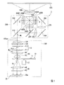
図1は、本発明の一実施形態に係るプロジェクター1の光学系を示す模式図である。なお、図1において、符号100axは照明光軸であり、照明装置100から色分離光学系200に向けて射出される光の光軸である。
FIG. 1 is a schematic diagram showing an optical system of a projector 1 according to an embodiment of the invention. In FIG. 1, reference numeral 100ax denotes an illumination optical axis, which is an optical axis of light emitted from the
図1に示すように、プロジェクター1は、照明装置100と、色分離光学系200と、液晶パネル400R,液晶パネル400Gおよび液晶パネル400Bと、クロスダイクロイックプリズム500と、投射光学系600と、を具備して構成されている。
As shown in FIG. 1, the projector 1 includes an
照明装置100は、励起光を照射するアレイ光源30と、集光光学系40と、蛍光体ホイール10と、コリメート光学系60と、インテグレーター光学系110と、偏光変換素子120と、重畳レンズ130と、がこの順に配置された構成になっている。
The
アレイ光源30は、固体光源としての複数の半導体レーザー30aを備える。複数の半導体レーザー30aは照明光軸100axと直交する同一面内において、アレイ状に並んで配置されている。半導体レーザー30aは、蛍光体層11を励起させる励起光BLとして、例えば、青色光(例えばピーク波長が460nmのレーザー光)を射出する。
The
集光光学系40は、複数の第1レンズ42と、1つの第2レンズ44と、を備えている。
各第1レンズ42及び第2レンズ44はともに凸レンズである。第2レンズ44には、第1レンズ42を透過した光が入射する。集光光学系40は、アレイ光源30から射出される励起光BLの光線軸上に配置され、複数のアレイ光源30から射出された励起光BLを集光する。
The condensing
Each of the
蛍光体ホイール10は、アレイ光源30から射出される青色の励起光BLの一部を透過させ、残りの励起光BLを蛍光に変換する機能を有する。蛍光体ホイール10は、蛍光体層11を有しており、この蛍光体層11は残りの励起光BLを吸収して赤色光及び緑色光を含む黄色の蛍光YLを射出する。蛍光YLの発光強度のピークは、約550nmである。蛍光YLと蛍光体層11を透過した励起光BLの一部の青色光BL1とが合成されることで白色の照明光WLが生成される。
The
コリメート光学系60は、蛍光体ホイール10からの照明光WLの広がりを抑える光学素子としての第1レンズ62と、第1レンズ62から入射される光を略平行化する第2レンズ64とを備えている。第1レンズ62は、蛍光体ホイール10から射出された照明光WLを取り込むピックアップレンズであり、蛍光体ホイール10に近接した状態で配置されている。
The collimating
コリメート光学系60は、蛍光体ホイール10から射出された照明光WLを略平行化してインテグレーター光学系110に入射させる。
The collimating
インテグレーター光学系110は、第1レンズアレイ111及び第2レンズアレイ112を備えている。第1レンズアレイ111はマトリクス状に配置された複数のレンズを備える。第2レンズアレイ112は、第1レンズアレイ111の複数のレンズに対応した複数のレンズを備える。第1レンズアレイ111は、コリメート光学系60からの照明光WLを複数の分割光束に分割するとともに、各分割光束を集光する。第2レンズアレイ112は、第1レンズアレイ111からの分割光束を適当な発散角にして射出する。
The integrator
偏光変換素子120は、例えば、偏光分離膜と位相差板とから構成され、照明光WLを直線偏光に変換する。
The
重畳レンズ130は、偏光変換素子120から射出された複数の分割光束を、液晶パネル400R、液晶パネル400G、液晶パネル400Bの各々の被照明領域において重畳させる。
The
色分離光学系200は、ダイクロイックミラー210、ダイクロイックミラー220、反射ミラー230、反射ミラー240、反射ミラー250及びリレーレンズ260、リレーレンズ270を備えている。色分離光学系200は、照明装置100からの光を赤色光、緑色光及び青色光に分離し、赤色光、緑色光及び青色光のそれぞれの色光を照明対象となる液晶パネル400R、液晶パネル400G、液晶パネル400Bに導く。色分離光学系200と、液晶パネル400R、液晶パネル400G及び液晶パネル400Bとの間には、集光レンズ300R、集光レンズ300G、集光レンズ300Bがそれぞれ配置されている。
The color separation
ダイクロイックミラー210は、赤色光成分を透過させ、緑色光成分及び青色光成分を反射する。ダイクロイックミラー220は、ダイクロイックミラー210で反射した照明光WLのうち、緑色光成分を反射して、青色光成分を透過させる。
The
反射ミラー230は、ダイクロイックミラー210を透過した赤色光成分を反射する。
反射ミラー240および反射ミラー250は、ダイクロイックミラー220を透過した青色光成分を反射する。
The
The
ダイクロイックミラー210を透過した赤色光は、反射ミラー230で反射され、集光レンズ300Rを透過して赤色光用の光変調装置としての液晶パネル400Rの画像形成領域に入射する。ダイクロイックミラー210で反射された緑色光は、ダイクロイックミラー220でさらに反射され、集光レンズ300Gを透過して緑色光用の光変調装置としての液晶パネル400Gの画像形成領域に入射する。ダイクロイックミラー220を透過した青色光は、リレーレンズ260、反射ミラー240、リレーレンズ270、反射ミラー250、集光レンズ300Bを経て青色光用の光変調装置としての液晶パネル400Bの画像形成領域に入射する。
The red light transmitted through the
液晶パネル400R、液晶パネル400Gおよび液晶パネル400Bは、入射された色光を画像情報に応じて変調して画像を形成する。液晶パネル400R、液晶パネル400Gおよび液晶パネル400Bは、照明装置100の照明対象となる。なお、図示を省略したが、集光レンズ300R、集光レンズ300Gおよび集光レンズ300Bと各液晶パネル400R、液晶パネル400Gおよび液晶パネル400Bとの間には、それぞれ入射側偏光板が配置されている。また、各液晶パネル400R、液晶パネル400Gおよび液晶パネル400Bとクロスダイクロイックプリズム500との間には、それぞれ射出側偏光板が配置されている。
The
例えば、液晶パネル400R、液晶パネル400Gおよび液晶パネル400Bの各々は、一対の透明基板に液晶を密閉封入した透過型の液晶パネルから構成される。
For example, each of the
クロスダイクロイックプリズム500は、図示は省略するが、射出側偏光板から射出された色光毎に変調された光学像を合成してカラー画像を形成する光学素子である。
Although not shown, the cross
クロスダイクロイックプリズム(光学素子)500から射出されたカラー画像は、複数のレンズから構成される投射光学系600によって拡大投射され、スクリーンSCR上で画像を形成する。
The color image emitted from the cross dichroic prism (optical element) 500 is enlarged and projected by the projection
ところで、液晶パネル400R、液晶パネル400Gおよび液晶パネル400Bは、温度変化によって印加電圧−光透過率特性(V−T特性)や応答速度が変動する。そのため、プロジェクター1は、上述の変動に伴って、表示画像の品質が低下するおそれがある。
By the way, in the
通常、緑色光に対応する液晶パネル400Gは、他の液晶パネル400Rおよび液晶パネル400Bに比べて、照明装置100からの入射光量が相対的に多い。そのため、液晶パネル400Gは、液晶パネル400Rおよび液晶パネル400Bに比べて、温度が上昇し易く、結果的に、プロジェクター1の駆動時に最も大きな温度変化が生じる。
以下、液晶パネル400R、液晶パネル400Gおよび液晶パネル400Bを総称して、液晶パネル400R,400G,400Bと称すこともある。
Normally, the
Hereinafter, the
本実施形態のプロジェクター1は、最も大きな温度変化が生じる液晶パネル400Gの温度を検出し、その検出結果に基づき、V−T特性の変動が小さくなるように各液晶パネル400R,400G,400Bの駆動させている。
The projector 1 according to the present embodiment detects the temperature of the
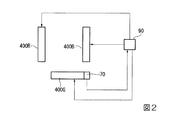
図2は、プロジェクター1の電気的な構成を模式的に示した図である。
図2に示すように、本実施形態のプロジェクター1は、液晶パネル400Gの温度を検出する温度センサー70と、温度センサー70の検出結果に基づいて、液晶パネル400R,400G,400Bの駆動を制御する制御部90と、を備えている。
FIG. 2 is a diagram schematically showing the electrical configuration of the projector 1.
As shown in FIG. 2, the projector 1 of the present embodiment controls the driving of the
温度センサー70は、最も大きな温度変化が生じる液晶パネル400Gの温度を検出するため、温度検出を簡便且つ確実に行うことが可能である。
本実施形態のプロジェクター1は、一つの液晶パネル400Gの温度を一個の温度センサー70で検出する構成を採用するため、装置構成を簡略化することができる。
Since the
Since the projector 1 according to the present embodiment employs a configuration in which the temperature of one
本実施形態において、温度センサー70としては、サーミスタや熱電対が用いられる。温度センサー70は、例えば、液晶パネル400Gへの入射光を遮らない位置に設けられる。温度センサー70は、制御部90と電気的に接続され、その検出結果を制御部90へと送信する。
In the present embodiment, a thermistor or a thermocouple is used as the
制御部90は、温度センサー70から送信される液晶パネル400Gの温度と液晶パネル400R,400G,400Bを駆動させる駆動電圧とを対応づけたデータを格納したルックアップテーブル(Look Up Table)を記憶している。なお、ルックアップテーブルは、例えば、事前に実施された実験に基づいて算出される。
The
具体的に、ルックアップテーブルは、液晶パネル400Gの温度と、該液晶パネル400Gの温度に基づいて液晶パネル400R,400G,400Bに生じるV−T特性の変動をそれぞれ補正する駆動電圧との関係を示すデータを格納したものである。通常、ルックアップテーブルは、±10℃程度の温度変化が生じる液晶パネルのV−T特性の変動を補正することが可能である。
Specifically, the look-up table shows the relationship between the temperature of the
ところで、近年、プロジェクターにおいても消費電力の削減(省エネルギー化)が望まれている。本実施形態のプロジェクター1は、鑑賞者の用途に応じて、照明装置100を定格電力で駆動する定格電力モードと、照明装置100を省電力で駆動する省電力モードとを切り替え可能となっている。
By the way, in recent years, reduction of power consumption (energy saving) is also desired for projectors. The projector 1 according to the present embodiment can be switched between a rated power mode in which the
省電力モードは、定格電力モードに対し、駆動する半導体レーザー30aの数を減らすことでアレイ光源30の消費電力を抑制するモードである。
The power saving mode is a mode in which the power consumption of the array
ここで、省電力モードと定格電力モードにおいて、照明装置100から照射される照明光WLの光量は異なる。そのため、省電力モード及び定格電力モードに対応したプロジェクター1において、温度センサー70における検出温度領域は、単一の電力モードに対応したプロジェクターよりも拡がる。つまり、各液晶パネルにおいては、一つのルックアップテーブルで良好に補正可能な温度範囲(±10℃)よりも広い(例えば±20℃)温度変化が生じることとなる。
このように複数の電力モードに対応したプリンターにおいては、一つのルックアップテーブルだけでは各液晶パネルに生じるV−T特性の変動を良好に補正することが難しくなる。
Here, in the power saving mode and the rated power mode, the amount of illumination light WL emitted from the
As described above, in a printer that supports a plurality of power modes, it is difficult to satisfactorily correct a variation in the VT characteristic generated in each liquid crystal panel with only one lookup table.
これに対し、本実施形態の制御部90は、温度センサー70の検出温度(液晶パネルの温度)が比較的低温領域の場合に生じるV−T特性の変動を補正するためのルックアップテーブルと、温度センサー70の検出温度(液晶パネルの温度)が比較的高温領域の場合に生じるV−T特性の変動を補正するためのルックアップテーブルとを個別に記憶している。
つまり、制御部90は、液晶パネルの温度範囲によって異なるV−T特性の変動をそれぞれ補正可能なルックアップテーブルを有している。
On the other hand, the
That is, the
このような構成に基づき、制御部90は、温度センサー70の検出結果(液晶パネル400Gの温度)に基づき、複数のルックアップテーブルの中から選択したテーブルを参照することで、各液晶パネル400R,400G,400Bを制御している。
Based on such a configuration, the
また、本実施形態のプロジェクター1は、複数のカラーモードで画像表示を行うことが可能である。ここで、カラーモードとは、鑑賞者の用途に応じて、投写画像の色合いを調整するためのモードである。 Further, the projector 1 of the present embodiment can display an image in a plurality of color modes. Here, the color mode is a mode for adjusting the hue of the projected image in accordance with the application of the viewer.
プロジェクター1は、3つのカラーモード、例えば、標準カラーモード、輝度優先カラーモード、色優先カラーモードに対応する。標準カラーモードは、輝度及び色合いのバランスが均等に調整された画像を表示するモードであり、輝度優先カラーモードは、色合いよりも輝度を優先して調整した画像を表示するモードであり、色優先カラーモードは、輝度よりも色あいを優先して調整した画像を表示するモードである。 The projector 1 corresponds to three color modes, for example, a standard color mode, a luminance priority color mode, and a color priority color mode. The standard color mode is a mode that displays an image in which the balance of brightness and hue is evenly adjusted, and the brightness priority color mode is a mode that displays an image adjusted by giving priority to brightness over hue, and color priority. The color mode is a mode for displaying an image adjusted by giving priority to the hue over the luminance.
プロジェクター1において、各液晶パネル400R,400G,400Bの駆動条件(透過率等)は、カラーモード毎に異なる。制御部90は、各カラーモードに対応したルックアップテーブルを記憶している。
In the projector 1, the driving conditions (transmittance, etc.) of the
このような構成に基づき、制御部90はカラーモードに応じたルックアップテーブルを参照することで、液晶パネル400R,400G,400Bを制御するようになっている。
Based on such a configuration, the
図3は制御部90に記憶されるルックアップテーブルを概念的に示した図である。
図3に示すように、本実施形態の制御部90には、例えば、6つのルックアップテーブルTB1〜TB6(以下、単にテーブルTB1〜TB6と称す)を記憶している。
FIG. 3 is a diagram conceptually showing a lookup table stored in the
As shown in FIG. 3, the
テーブルTB1、TB2は、標準カラーモードに対応し、テーブルTB3、TB4は、輝度優先カラーモードに対応し、テーブルTB5、TB6は、色優先カラーモードに対応する。 The tables TB1 and TB2 correspond to the standard color mode, the tables TB3 and TB4 correspond to the luminance priority color mode, and the tables TB5 and TB6 correspond to the color priority color mode.
つまり、標準カラーモードが選択されている場合、制御部90は温度センサー70の検出結果に基づいてテーブルTB1、TB2のいずれか一方を選択する。
テーブルTB1は、温度センサー70の検出結果が所定の閾値よりも低い場合(通常、省電力モードで照明装置100を駆動させた場合)に、制御部90により選択されるテーブルである。
テーブルTB2は、温度センサー70の検出結果が所定の閾値よりも高い場合(通常、定常電力モードで照明装置100を駆動させた場合)に、制御部90により選択されるテーブルである。
That is, when the standard color mode is selected, the
The table TB1 is a table selected by the
The table TB2 is a table selected by the
輝度優先モードが選択されている場合、制御部90は温度センサー70の検出結果に基づいてテーブルTB3、TB4のいずれか一方を選択する。
テーブルTB3は、温度センサー70の検出結果が所定の閾値よりも低い場合(通常、省電力モードで照明装置100を駆動させた場合)に、制御部90により選択されるテーブルである。
テーブルTB4は、温度センサー70の検出結果が所定の閾値よりも高い場合(通常、定格電力モードで照明装置100を駆動させた場合)に、制御部90により選択されるテーブルである。
When the luminance priority mode is selected, the
The table TB3 is a table selected by the
The table TB4 is a table selected by the
色優先モードが選択されている場合、制御部90は温度センサー70の検出結果に基づいてテーブルTB5、TB6のいずれか一方を選択する。
テーブルTB5は、温度センサー70の検出結果が所定の閾値よりも低い場合(通常、省電力モードで照明装置100を駆動させた場合)に、制御部90により選択されるテーブルである。
テーブルTB6は、温度センサー70の検出結果が所定の閾値よりも高い場合(通常、定格電力モードで照明装置100を駆動させた場合)に、制御部90により選択されるテーブルである。
When the color priority mode is selected, the
The table TB5 is a table selected by the
The table TB6 is a table selected by the
続いて、本実施形態のプロジェクター1の動作の一例について説明する。この説明では、プロジェクター1がカラーモードとして標準モードを採用した場合について説明する。 Next, an example of the operation of the projector 1 according to this embodiment will be described. In this description, a case where the projector 1 adopts the standard mode as the color mode will be described.
本実施形態のプロジェクター1は、画像表示を行う際、温度センサー70の検出結果に基づいて選択したテーブルを参照することで、各液晶パネル400R,400G,400Bの駆動を制御する。
When performing image display, the projector 1 according to the present embodiment controls the driving of the
具体的に、制御部90は、温度センサー70の検出結果を所定の閾値と比較する。制御部90は温度センサー70の検出結果が所定の閾値よりも低い場合、テーブルTB1を選択し、テーブルTB1を参照することで各液晶パネル400R,400G,400Bの駆動を制御する。一方、制御部90は温度センサー70の検出結果が所定の閾値よりも高い場合、テーブルTB2を選択し、テーブルTB2を参照することで各液晶パネル400R,400G,400Bの駆動を制御する。
Specifically, the
プロジェクター1の動作中において、制御部90は温度センサー70の検出結果を所定の閾値と比較し続ける。そして、比較結果に応じて、各液晶パネル400R,400G,400Bの駆動に用いるテーブルTB1,TB2の一方から選択する。
このように本実施形態のプロジェクター1によれば、温度センサー70の検出結果に基づいて最適なルックアップテーブルを選択するため、省電力モード及び定格電力モードによらず、各液晶パネル400R,400G,400Bで生じるV−T特性の変動を良好に補正して、表示画像の品質低下を抑制することができる。
During the operation of the projector 1, the
As described above, according to the projector 1 of the present embodiment, since the optimum lookup table is selected based on the detection result of the
なお、プロジェクター1を同一条件で駆動した場合でも、プロジェクター1の外部環境(外気温、湿度など)によって液晶パネル400R,400G,400Bの温度に差が生じる。すなわち、省電力モードで駆動する場合であっても、外気温が高い場合、液晶パネルの温度が高くなることも想定される。同様に、定格電力モードで駆動する場合であっても、外気温が低い場合、液晶パネルの温度が低くなることも想定される。
そのため、電力モードに応じてテーブルを選択した場合、外気温によって所望のテーブルが選択されず、液晶パネルに生じるV−T特性の変動を良好に補正できないおそれがある。
Even when the projector 1 is driven under the same conditions, the temperature of the
Therefore, when a table is selected according to the power mode, a desired table is not selected depending on the outside air temperature, and there is a possibility that the variation in the VT characteristic generated in the liquid crystal panel cannot be corrected well.
これに対し、本実施形態によれば、液晶パネル400R,400G,400Bの温度のみに着目して最適なルックアップテーブルを選択ため、外気温を考慮する必要が無く、照明装置100を複数のモードで駆動する場合においても液晶パネルに生じるV−T特性の変動を良好に補正することで良質な画像を表示することができる。
On the other hand, according to the present embodiment, the optimum look-up table is selected by paying attention only to the temperatures of the
なお、本発明の技術範囲は上記実施形態に限定されるものではなく、本発明の趣旨を逸脱しない範囲において種々の変更を加えることが可能である。 The technical scope of the present invention is not limited to the above embodiment, and various modifications can be made without departing from the spirit of the present invention.
例えば上記実施形態では、照明装置100として半導体レーザー30aと蛍光体層11を用いて照明光WLを生成するものを例示したが、本発明はこれに限定されず、超高圧水銀ランプなどの放電ランプを照明装置として用いても良い。
For example, in the above-described embodiment, the
また、上記実施形態では、温度センサー70を液晶パネル400Gに設ける場合を例に挙げたが、液晶パネル400R又は液晶パネル400Bのいずれかに設けるようにしても良い。
In the above embodiment, the
また、プロジェクター1において、例えば、電源投入状態のまま液晶パネルに映像信号が所定時間入力されない状態が続いた場合、照明装置100を定格電力モードから省電力モードに自動的に切り替えても良い。このようにすれば、プロジェクター1における待機電力を減らすことができるので、さらなる省エネルギー化を図ることができる。
また、外部環境(外気温、湿度、明るさなど)に応じて、カラーモードや、照明装置100の駆動モード(定格電力モード又は省電力モード)を切り替えるようにしても良い。
Further, in the projector 1, for example, when a state in which a video signal is not input to the liquid crystal panel for a predetermined time in a power-on state continues, the
Further, the color mode and the driving mode (rated power mode or power saving mode) of the
また、上記実施形態では、透過型の蛍光体ホイールを備えた照明装置の例を挙げたが、反射型の蛍光体ホイールを備えた照明装置であってもよい。 Moreover, although the example of the illuminating device provided with the transmissive | pervious phosphor wheel was given in the said embodiment, the illuminating device provided with the reflective phosphor wheel may be sufficient.
1…プロジェクター、100…照明装置、200…色分離光学系、400R,400G,400B…液晶パネル、TB1,TB2,TB3,TB,4,TB5,TB6…テーブル(ルックアップテーブル)、WL…照明光。 DESCRIPTION OF SYMBOLS 1 ... Projector, 100 ... Illuminating device, 200 ... Color separation optical system, 400R, 400G, 400B ... Liquid crystal panel, TB1, TB2, TB3, TB, 4, TB5, TB6 ... Table (lookup table), WL ... Illumination light .
Claims (4)
前記照明装置からの照明光を色分離する色分離光学系と、
前記色分離光学系により分離された各色に対応して配置される複数の液晶パネルと、
駆動電圧に関するデータを格納したルックアップテーブルを複数有し、前記複数のルックアップテーブルの中から選択したテーブルを参照することで、前記複数の液晶パネルを制御する制御部と、
前記複数の液晶パネルのいずれかに設けられる一つの温度センサーと、を備え、
前記制御部は、前記温度センサーの検出結果に基づいて、前記複数の液晶パネルの制御に用いる前記ルックアップテーブルを選択する
プロジェクター。 A lighting device;
A color separation optical system for color-separating illumination light from the illumination device;
A plurality of liquid crystal panels arranged corresponding to the respective colors separated by the color separation optical system;
A plurality of look-up tables storing data relating to drive voltage, and a control unit for controlling the plurality of liquid crystal panels by referring to a table selected from the plurality of look-up tables;
One temperature sensor provided in any of the plurality of liquid crystal panels,
The control unit selects the look-up table used for controlling the plurality of liquid crystal panels based on a detection result of the temperature sensor.
前記温度センサーは、前記緑色の光に対応して配置される前記液晶パネルに設けられる
請求項1に記載のプロジェクター。 The color separation optical system separates the white illumination light emitted from the illumination device into red, blue and green light,
The projector according to claim 1, wherein the temperature sensor is provided in the liquid crystal panel arranged corresponding to the green light.
請求項1又は2に記載のプロジェクター。 The projector according to claim 1, wherein the lighting device includes a solid light source and a wavelength conversion element on which light emitted from the solid light source is incident.
請求項1乃至3のいずれか一項に記載のプロジェクター。 4. The lighting device is driven in either a rated power mode or a power saving mode in which a lower voltage is applied to the liquid crystal panel than in the rated power mode. 5. The projector described.
Priority Applications (1)
| Application Number | Priority Date | Filing Date | Title |
|---|---|---|---|
| JP2016008896A JP2017129730A (en) | 2016-01-20 | 2016-01-20 | projector |
Applications Claiming Priority (1)
| Application Number | Priority Date | Filing Date | Title |
|---|---|---|---|
| JP2016008896A JP2017129730A (en) | 2016-01-20 | 2016-01-20 | projector |
Publications (2)
| Publication Number | Publication Date |
|---|---|
| JP2017129730A true JP2017129730A (en) | 2017-07-27 |
| JP2017129730A5 JP2017129730A5 (en) | 2019-02-21 |
Family
ID=59395643
Family Applications (1)
| Application Number | Title | Priority Date | Filing Date |
|---|---|---|---|
| JP2016008896A Withdrawn JP2017129730A (en) | 2016-01-20 | 2016-01-20 | projector |
Country Status (1)
| Country | Link |
|---|---|
| JP (1) | JP2017129730A (en) |
Cited By (1)
| Publication number | Priority date | Publication date | Assignee | Title |
|---|---|---|---|---|
| CN111583846A (en) * | 2020-04-28 | 2020-08-25 | 青岛海信激光显示股份有限公司 | Laser display equipment |
Families Citing this family (1)
| Publication number | Priority date | Publication date | Assignee | Title |
|---|---|---|---|---|
| JP7567388B2 (en) | 2020-11-17 | 2024-10-16 | セイコーエプソン株式会社 | Liquid crystal projector and method for controlling liquid crystal projector |
Citations (14)
| Publication number | Priority date | Publication date | Assignee | Title |
|---|---|---|---|---|
| JPH1039772A (en) * | 1996-07-29 | 1998-02-13 | Mitsubishi Electric Corp | Projection type liquid crystal display device |
| JP2003043440A (en) * | 2001-07-26 | 2003-02-13 | Toshiba Corp | Liquid crystal projection type display device |
| JP2004102244A (en) * | 2003-07-07 | 2004-04-02 | Hitachi Ltd | Liquid crystal display |
| JP2005274995A (en) * | 2004-03-25 | 2005-10-06 | Seiko Epson Corp | Suppression of temperature rise of projection-side polarizing plate constituting liquid crystal light valve |
| JP2008233777A (en) * | 2007-03-23 | 2008-10-02 | Canon Inc | Light modulating element unit and image display device having the same |
| JP2009294266A (en) * | 2008-06-02 | 2009-12-17 | Canon Inc | Image display device and image display system |
| JP2010252018A (en) * | 2009-04-15 | 2010-11-04 | Funai Electric Co Ltd | Television device with disk device |
| JP2011053533A (en) * | 2009-09-03 | 2011-03-17 | Mitsubishi Electric Corp | Image display device |
| JP2012252062A (en) * | 2011-05-31 | 2012-12-20 | Sanyo Electric Co Ltd | Liquid crystal display device |
| JP2013134384A (en) * | 2011-12-27 | 2013-07-08 | Seiko Epson Corp | Projector and control method for projector |
| JP2015022154A (en) * | 2013-07-19 | 2015-02-02 | セイコーエプソン株式会社 | Image display apparatus and control method |
| JP2015129783A (en) * | 2014-01-06 | 2015-07-16 | セイコーエプソン株式会社 | Image display device, projector and control method thereof |
| WO2016002269A1 (en) * | 2014-07-03 | 2016-01-07 | ソニー株式会社 | Phosphor wheel, light source unit, and image display device |
| JP2016006523A (en) * | 2011-09-22 | 2016-01-14 | 台達電子工業股▲ふん▼有限公司 | Projection device |
-
2016
- 2016-01-20 JP JP2016008896A patent/JP2017129730A/en not_active Withdrawn
Patent Citations (14)
| Publication number | Priority date | Publication date | Assignee | Title |
|---|---|---|---|---|
| JPH1039772A (en) * | 1996-07-29 | 1998-02-13 | Mitsubishi Electric Corp | Projection type liquid crystal display device |
| JP2003043440A (en) * | 2001-07-26 | 2003-02-13 | Toshiba Corp | Liquid crystal projection type display device |
| JP2004102244A (en) * | 2003-07-07 | 2004-04-02 | Hitachi Ltd | Liquid crystal display |
| JP2005274995A (en) * | 2004-03-25 | 2005-10-06 | Seiko Epson Corp | Suppression of temperature rise of projection-side polarizing plate constituting liquid crystal light valve |
| JP2008233777A (en) * | 2007-03-23 | 2008-10-02 | Canon Inc | Light modulating element unit and image display device having the same |
| JP2009294266A (en) * | 2008-06-02 | 2009-12-17 | Canon Inc | Image display device and image display system |
| JP2010252018A (en) * | 2009-04-15 | 2010-11-04 | Funai Electric Co Ltd | Television device with disk device |
| JP2011053533A (en) * | 2009-09-03 | 2011-03-17 | Mitsubishi Electric Corp | Image display device |
| JP2012252062A (en) * | 2011-05-31 | 2012-12-20 | Sanyo Electric Co Ltd | Liquid crystal display device |
| JP2016006523A (en) * | 2011-09-22 | 2016-01-14 | 台達電子工業股▲ふん▼有限公司 | Projection device |
| JP2013134384A (en) * | 2011-12-27 | 2013-07-08 | Seiko Epson Corp | Projector and control method for projector |
| JP2015022154A (en) * | 2013-07-19 | 2015-02-02 | セイコーエプソン株式会社 | Image display apparatus and control method |
| JP2015129783A (en) * | 2014-01-06 | 2015-07-16 | セイコーエプソン株式会社 | Image display device, projector and control method thereof |
| WO2016002269A1 (en) * | 2014-07-03 | 2016-01-07 | ソニー株式会社 | Phosphor wheel, light source unit, and image display device |
Cited By (2)
| Publication number | Priority date | Publication date | Assignee | Title |
|---|---|---|---|---|
| CN111583846A (en) * | 2020-04-28 | 2020-08-25 | 青岛海信激光显示股份有限公司 | Laser display equipment |
| CN111583846B (en) * | 2020-04-28 | 2024-04-26 | 青岛海信激光显示股份有限公司 | Laser display equipment |
Similar Documents
| Publication | Publication Date | Title |
|---|---|---|
| US8979278B2 (en) | Light source device and projection apparatus which adjusts a light emission state of first and second light sources based on one of detected light intensity values and an accumulated light emission time, and projection method and non-transitory storage medium | |
| JP6417709B2 (en) | Projector and projector control method | |
| JP6452172B2 (en) | Illumination device, wheel deterioration detection method, and projector | |
| US10091478B2 (en) | Projection display apparatus | |
| JP4799629B2 (en) | Projection display device | |
| RU2629889C1 (en) | Image display device and method for controlling image display device | |
| JP2015129783A (en) | Image display device, projector and control method thereof | |
| US20130286357A1 (en) | Optical system and projection display apparatus using the same | |
| US20090033879A1 (en) | Projector apparatus and control method for projector apparatus | |
| KR101798158B1 (en) | Light source device and projector comprising the same | |
| WO2016047464A1 (en) | Illuminating device, light source control method, and projection type display device | |
| JP2017129730A (en) | projector | |
| JP6683085B2 (en) | LCD projector | |
| WO2018083895A1 (en) | Projection-type display device and method for controlling same | |
| JP2008089836A (en) | projector | |
| JP4811488B2 (en) | Projection display | |
| US20120133896A1 (en) | Projection-type Image Display Device | |
| JP6680166B2 (en) | LCD projector | |
| JP2016114738A (en) | projector | |
| JP4335664B2 (en) | Projection type image display device, rear projection type image display device, optical unit and screen unit | |
| JP2015001581A (en) | Projector | |
| JP7098483B2 (en) | Light source device and image projection device | |
| US20180220111A1 (en) | Projector and method of controlling projector | |
| JP2012242457A (en) | Projection type display device | |
| JP2005077890A (en) | Projection type image display device and illuminance detection adjustment method |
Legal Events
| Date | Code | Title | Description |
|---|---|---|---|
| RD03 | Notification of appointment of power of attorney |
Free format text: JAPANESE INTERMEDIATE CODE: A7423 Effective date: 20181026 |
|
| A521 | Request for written amendment filed |
Free format text: JAPANESE INTERMEDIATE CODE: A523 Effective date: 20190108 |
|
| A621 | Written request for application examination |
Free format text: JAPANESE INTERMEDIATE CODE: A621 Effective date: 20190108 |
|
| A977 | Report on retrieval |
Free format text: JAPANESE INTERMEDIATE CODE: A971007 Effective date: 20191010 |
|
| A131 | Notification of reasons for refusal |
Free format text: JAPANESE INTERMEDIATE CODE: A131 Effective date: 20191023 |
|
| A521 | Request for written amendment filed |
Free format text: JAPANESE INTERMEDIATE CODE: A523 Effective date: 20191128 |
|
| A131 | Notification of reasons for refusal |
Free format text: JAPANESE INTERMEDIATE CODE: A131 Effective date: 20200310 |
|
| A761 | Written withdrawal of application |
Free format text: JAPANESE INTERMEDIATE CODE: A761 Effective date: 20200318 |