JP5779221B2 - Game machine - Google Patents

Game machine Download PDF

Info

Publication number
JP5779221B2
JP5779221B2 JP2013231091A JP2013231091A JP5779221B2 JP 5779221 B2 JP5779221 B2 JP 5779221B2 JP 2013231091 A JP2013231091 A JP 2013231091A JP 2013231091 A JP2013231091 A JP 2013231091A JP 5779221 B2 JP5779221 B2 JP 5779221B2
Authority
JP
Japan
Prior art keywords
time
display
data
command
setting
Prior art date
Legal status (The legal status is an assumption and is not a legal conclusion. Google has not performed a legal analysis and makes no representation as to the accuracy of the status listed.)
Active
Application number
JP2013231091A
Other languages
Japanese (ja)
Other versions
JP2014111066A (en
JP2014111066A5 (en
Inventor
中島 和俊
和俊 中島
Current Assignee (The listed assignees may be inaccurate. Google has not performed a legal analysis and makes no representation or warranty as to the accuracy of the list.)
Sankyo Co Ltd
Original Assignee
Sankyo Co Ltd
Priority date (The priority date is an assumption and is not a legal conclusion. Google has not performed a legal analysis and makes no representation as to the accuracy of the date listed.)
Filing date
Publication date
Application filed by Sankyo Co Ltd filed Critical Sankyo Co Ltd
Priority to JP2013231091A priority Critical patent/JP5779221B2/en
Publication of JP2014111066A publication Critical patent/JP2014111066A/en
Publication of JP2014111066A5 publication Critical patent/JP2014111066A5/ja
Application granted granted Critical
Publication of JP5779221B2 publication Critical patent/JP5779221B2/en
Active legal-status Critical Current
Anticipated expiration legal-status Critical

Links

Images

Description

本発明は、パチンコ遊技機、コイン遊技機、スロットマシンなどで代表される遊技機に関する。詳しくは、識別情報の可変表示を実行する遊技を行う遊技機に関する。 The present invention relates to a gaming machine represented by a pachinko gaming machine, a coin gaming machine, a slot machine and the like. Specifically, the present invention relates to a gaming machine that performs a game for performing variable display of identification information .

この種の遊技機として従来から一般的に知られているものに、たとえば、遊技の演出を行なう変動表示装置等の演出装置を備え、遊技において変動表示装置の変動表示結果が特定の表示結果となる等の特定の条件が成立したときに、遊技者にとって有利な特定遊技状態(大当り遊技状態)に制御されるパチンコ遊技機等の遊技機がある。   What is conventionally known as this type of gaming machine is, for example, provided with an effect device such as a variable display device for effecting a game, and in the game, the variable display result of the variable display device is a specific display result. There is a gaming machine such as a pachinko gaming machine that is controlled to a specific gaming state (big hit gaming state) that is advantageous to the player when a specific condition is established.

このような遊技機では、時計機能およびカレンダ機能等の計時機能を有し、計時機能により得られる現在の時刻等の情報に基づいて、変動表示装置での表示態様を変更するものがあった。このような現在時刻を管理する遊技機の一例としては、内部時計よりなる計時手段を用いて現在時刻を把握して、演出表示画面で時刻に関する表示を行ない、遊技場の閉店までの残り時間に応じて、時刻に関する表示内容を変更するものがあった(特許文献1)。   Some of these gaming machines have timekeeping functions such as a clock function and a calendar function, and change the display mode on the variable display device based on information such as the current time obtained by the timekeeping function. As an example of a gaming machine that manages such a current time, the current time is grasped by using a time measuring means consisting of an internal clock, the time is displayed on the effect display screen, and the remaining time until the game hall is closed. In response to this, there is one that changes the display content related to the time (Patent Document 1).

また、このような計時手段を備えた遊技機では、電源オフオン時間を監視することにより不正行為を識別し、不正行為による設定変更を防止するために、計時手段の計時値を用いて、電源オフ時刻のデータを、電源バックアップされた記憶手段に記憶するものがあった(特許文献2)。   In addition, in a gaming machine equipped with such a time measuring means, it is possible to identify a fraudulent activity by monitoring the power off / on time, and to prevent setting changes due to the fraudulent action, the time value of the time measuring means is used to turn off the power. There is one that stores time data in a storage unit that is backed up by a power source (Patent Document 2).

特開2004−357726号公報(図5、図12、段落番号0066〜0073、0091〜0094)JP-A-2004-357726 (FIGS. 5 and 12, paragraph numbers 0066 to 0073, 0091 to 0094) 特開2005−192723号公報(段落番号0057,0058)JP-A-2005-192723 (paragraph numbers 0057 and 0058)

本発明の目的は、日時を特定可能とする計時手段の計時値に基づいて実行される所定の演出の表示態様が変更されることを特定可能に報知することである。 This onset bright object is to identifiable notified that the display mode of predetermined effect to be executed based on the time count value of the counting means allowing specifying the date and time are changed.

(1) 識別情報の可変表示を実行する遊技を行う遊技機であって、
遊技の進行を制御する遊技制御手段と、
該遊技制御手段が送信するコマンドに基づいて演出装置の制御を行なう演出制御手段とを備え、
前記演出制御手段は、
計時手段としてのリアルタイムクロックと、
前記計時手段の計時に応じたデータが所定条件を満たしたときに、遊技演出における表示態様を変更する表示態様変更手段と、
該表示態様変更手段による遊技演出における表示態様の変更を予告する表示態様予告演出を実行する予告演出実行手段とを含み、
前記予告演出実行手段は、少なくとも前記識別情報の可変表示が実行されていないときに前記表示態様予告演出を実行する。
このような構成によれば、表示態様予告演出が実行されることにより、遊技演出の表示態様が変更されることを特定可能に報知することができる。
(2) 上記(1)の遊技機において、前記予告演出実行手段は、遊技演出の状態に応じて前記表示態様予告演出を実行可能である。
(3) 上記(1)または(2)の遊技機において、前記予告演出実行手段は、前記表示態様が変更される日時が特定可能な態様で、前記表示態様予告演出を実行する。
なお、以下の構成を備えるものでもよい。
遊技の演出を行なう演出装置(変動表示装置9、装飾ランプ25等の各種ランプ、スピーカ27)を備え、遊技において特定の条件が成立したとき(変動表示結果が大当り表示結果となったとき)に、遊技者にとって有利な特定遊技状態(大当り遊技状態)に制御される遊技機(パチンコ遊技機1)であって、
日時を特定可能とする計時を行なう計時手段(図5等のリアルタイムクロック353)と、
該計時手段の計時値により特定される日時に対応して前記演出装置により実行させる所定の演出(特別のデモンストレーション表示、オールマイティー図柄を用いた飾り図柄の変動表示)の内容を特定可能な演出情報(特別のデモ表示、オールマイティー図柄を用いた飾り図柄の変動表示を実行させるプロセスデータ等のデータ)を記憶する演出内容記憶手段(ROM84)と、
前記計時手段の計時値により特定される日時に対応して、前記演出内容記憶手段に記憶された前記演出情報に基づいて前記演出装置により前記所定の演出を実行させる計時対応演出実行手段(図41のS7604,S7606〜S7609、図42のS7660〜S7663、図45のS1810〜S1812,S1816〜S1818,S1820、図48のS825〜S828、図50のS1851〜S1859、図51のS1872)と、
所定の操作を行なうことが可能な操作手段(操作ボタン120、クリアスイッチ912
、演出スイッチ354)と、
前記計時対応演出実行手段により実行させる前記所定の演出の実行条件であって当該演出を実行する日時に関する情報(ROM359のゴールデンタイム設定データ領域に記憶された固定実行条件情報およびバックアップRAM356のゴールデンタイム設定領域に記憶された設定実行条件情報のそれぞれが、演出を実行する時刻に関する情報を含む旨開示、ROM359のオールマイティー図柄設定データ領域に記憶された固定実行条件情報およびバックアップRAM356のオールマイティー図柄設定領域に記憶された設定実行条件情報のそれぞれが、演出を実行する日時を示す情報を含む旨開示)および当該演出の種類に関する情報(ROM359のゴールデンタイム設定データ領域に記憶された固定実行条件情報およびバックアップRAM356のゴールデンタイム設定領域に記憶された設定実行条件情報のそれぞれが、演出の種類を示す情報を含む旨開示、ROM359のオールマイティー図柄設定データ領域に記憶された固定実行条件情報およびバックアップRAM356のオールマイティー図柄設定領域に記憶された設定実行条件情報のそれぞれが、演出の種類を示す情報を含む旨開示)を含む実行条件を設定(データを書換えること、および、データを初期化することを含み、実行条件を調整すること)するために予め定められた演出設定手順(図27のゴールデンタイム設定手順、オールマイティー図柄設定手順等、図30のS925〜S928、図31のS501〜S514)に基づき、前記操作手段により前記所定の演出の実行条件を設定するための操作(図21、図27の電源投入時の操作、選択設定操作および設定・終了操作)が行なわれたことに応じて、前記計時対応演出実行手段により実行させる前記所定の演出の実行条件を設定する演出設定手段(図30のS925〜S928、図31のS501〜S514)と、
揮発性の記憶手段であって、前記演出設定手段により設定された前記所定の演出の実行条件を特定可能な第1の実行条件情報(特別のデモンストレーション表示を実行する時刻として選択された時刻の情報等の設定実行条件情報)を記憶する(図7(b)のゴールデンタイム設定領域に記憶する、図7(b)のオールマイティー図柄設定領域に記憶する)第1の実行条件記憶手段(バックアップRAM356)と、
不揮発性の記憶手段であって、予め設定された前記所定の演出の実行条件を特定可能な第2の実行条件情報(必ず特別のデモンストレーション表示を実行する時刻として設定された時刻の情報、必ずオールマイティー図柄を用いた飾り図柄の変動表示を実行する日として設定された日の情報等の固定実行条件情報)を記憶する(図7(a)のゴールデンタイム設定データ領域に記憶する、図7(a)のオールマイティー図柄設定データ領域に記憶する)第2の実行条件記憶手段(ROM359)と、
前記遊技機への電力供給が停止している場合でも、所定時間は前記計時手段および前記第1の実行条件記憶手段のそれぞれに動作用の電力を供給する電力供給手段(バックアップ電源回路355)とを含み、
前記計時対応演出実行手段は、前記第1の実行条件記憶手段に記憶された前記第1の実行条件情報および前記第2の実行条件記憶手段に記憶された前記第2の実行条件情報のそれぞれに基づいて、前記計時手段の計時値により特定される日時に対応して、前記所定の演出を実行させる(図41のS7604,S7606〜S7609、図42のS7660〜S7663、図45のS1810〜S1812,S1816〜S1818,S1820、図48のS825〜S828、図50のS1851〜S1859、図51のS1872)。
(1) A gaming machine for performing a game for performing variable display of identification information,
Game control means for controlling the progress of the game;
Effect control means for controlling the effect device based on a command transmitted by the game control means,
The production control means includes
A real-time clock as a timekeeping means,
Display mode changing means for changing the display mode in the game effect when the data according to the timing of the timing unit satisfies a predetermined condition;
A notice effect execution means for executing a display aspect notice effect for notifying a change in the display form in the game effect by the display form change means,
The notice effect executing means executes the display mode notice effect at least when the variable display of the identification information is not executed.
According to such a configuration, it is possible to notify that it is possible to specify that the display mode of the game effect is changed by executing the display mode notice effect.
(2) In the gaming machine of (1), the notice effect executing means can execute the display mode notice effect according to the state of the game effect.
(3) In the gaming machine of the above (1) or (2), the advance notice execution means executes the display form advance notice in a form in which the date and time when the display form is changed can be specified.
In addition, you may provide the following structures.
When an effect device for effecting a game (various display device 9, various lamps such as a decoration lamp 25, speaker 27) is provided and a specific condition is established in the game (when the variable display result becomes a jackpot display result) A gaming machine (pachinko gaming machine 1) controlled to a specific gaming state (big hit gaming state) advantageous to the player,
Clocking means (time clock 353 in FIG. 5 etc.) for clocking time and date can be specified;
Production information that can specify the contents of a predetermined production (special demonstration display, variation display of decorative design using an almighty design) executed by the production device corresponding to the date and time specified by the time value of the time measuring means ( Effect content storage means (ROM 84) for storing special demo display, data such as process data for executing decorative display variation display using almighty design,
Corresponding to the date and time specified by the time value of the time measuring means, the time corresponding effect executing means for executing the predetermined effect by the effect device based on the effect information stored in the effect content storing means (FIG. 41). S7604, S7606 to S7609, S7660 to S7663 of FIG. 42, S1810 to S1812, S1816 to S1818, S1820 of FIG. 45, S825 to S828 of FIG. 48, S1851 to S1859 of FIG. 50, S1872 of FIG.
Operation means capable of performing a predetermined operation (operation button 120, clear switch 912
, Production switch 354),
Information regarding the execution date of the predetermined effect executed by the time-corresponding effect execution means and the date and time when the effect is executed (fixed execution condition information stored in the golden time setting data area of the ROM 359 and the golden time setting of the backup RAM 356) Disclosure that each of the setting execution condition information stored in the area includes information related to the execution time of the effect, the fixed execution condition information stored in the almighty symbol setting data area of the ROM 359, and the almighty symbol setting area of the backup RAM 356 Each of the set execution condition information is disclosed to include information indicating the date and time when the effect is executed) and information regarding the type of the effect (fixed execution condition information and backup stored in the golden time setting data area of the ROM 359) Disclosure that each of the setting execution condition information stored in the golden time setting area of AM 356 includes information indicating the type of effect, fixed execution condition information stored in the almighty symbol setting data area of ROM 359, and the almighty symbol of backup RAM 356 Each of the setting execution condition information stored in the setting area includes execution conditions including setting (rewriting data and initializing data) including execution conditions including information indicating the type of effect. The above operation is performed based on a production setting procedure (S925 to S928 in FIG. 30, S501 to S514 in FIG. 31, such as golden time setting procedure and almighty symbol setting procedure in FIG. Operation for setting the execution condition of the predetermined effect by means ( 21, an effect setting for setting execution conditions for the predetermined effect to be executed by the time corresponding effect executing means in response to the power-on operation, selection setting operation, and setting / ending operation in FIG. Means (S925 to S928 in FIG. 30, S501 to S514 in FIG. 31);
Volatile storage means, which is first execution condition information that can specify an execution condition of the predetermined effect set by the effect setting means (information of a time selected as a time for executing a special demonstration display) The first execution condition storage means (backup RAM 356) is stored (stored in the golden time setting area in FIG. 7B, stored in the almighty symbol setting area in FIG. 7B). When,
Second execution condition information (non-volatile storage means that can specify the execution condition of the predetermined effect set in advance (the information of the time set as the time for executing the special demonstration display, always the almighty) 7 (a fixed execution condition information such as date information set as a date for executing the variable display of decorative symbols using symbols) is stored (stored in the golden time setting data area of FIG. 7A). ) Second execution condition storage means (ROM 359) stored in the almighty symbol setting data area)
Power supply means (backup power supply circuit 355) for supplying power for operation to each of the time measuring means and the first execution condition storage means for a predetermined time even when power supply to the gaming machine is stopped Including
The time-corresponding effect execution means is provided for each of the first execution condition information stored in the first execution condition storage means and the second execution condition information stored in the second execution condition storage means. Based on the date and time specified by the time value of the time measuring means, the predetermined effect is executed (S7604, S7606 to S7609 in FIG. 41, S7660 to S7663 in FIG. 42, S1810 to S1812 in FIG. 45, S1816 to S1818, S1820, S825 to S828 in FIG. 48, S1851 to S1859 in FIG. 50, and S1872 in FIG.

このような構成によれば、たとえば、遊技機への電力供給が停止している場合に電力供給手段から供給される動作用の電力が停止したことにより第1の実行条件情報が消滅したこと、および、人為的な理由により第1の実行条件情報が消滅したこと等により、第1の実行条件記憶手段に記憶されている第1の実行条件情報が消滅しても、予め定められた第2の実行条件情報が不揮発性の記憶手段に記憶されているので、当該第2の実行条件情報に基づいて、計時手段の計時値により特定される日時に対応した所定の演出を実行させることができるようになる。また、所定の演出の実行条件が、当該演出を実行する日時に関する情報を含むので、演出を実行する日時に関する情報に基づいて、所定の演出を実行させることができる。さらに所定の演出の実行条件が、当該演出の種類に関する情報を含むので、演出の種類に関する情報に基づいて、所定の演出を実行させることができる。   According to such a configuration, for example, when the power supply to the gaming machine is stopped, the first execution condition information has disappeared due to the stop of the operation power supplied from the power supply means, And even if the first execution condition information stored in the first execution condition storage means disappears due to the disappearance of the first execution condition information due to human reasons, the predetermined second Since the execution condition information is stored in the non-volatile storage means, a predetermined effect corresponding to the date and time specified by the time value of the time measurement means can be executed based on the second execution condition information. It becomes like this. Further, since the execution condition of the predetermined effect includes information regarding the date and time when the effect is executed, the predetermined effect can be executed based on the information regarding the date and time when the effect is executed. Furthermore, since the execution condition of the predetermined effect includes information regarding the type of the effect, the predetermined effect can be executed based on the information regarding the type of effect.

パチンコ遊技機を正面からみた正面図である。It is the front view which looked at the pachinko game machine from the front. 遊技制御基板(主基板)の回路構成例を示すブロック図である。It is a block diagram which shows the circuit structural example of a game control board (main board). 中継基板、演出制御基板、ランプドライバ基板および音声出力基板の回路構成例を示すブロック図である。It is a block diagram which shows the circuit structural example of a relay board | substrate, an effect control board | substrate, a lamp driver board | substrate, and an audio | voice output board | substrate. リアルタイムクロックの構成例を示すブロック図である。It is a block diagram which shows the structural example of a real-time clock. 演出制御基板、ランプドライバ基板および音声出力基板の回路構成例を示すブロック図である。It is a block diagram showing an example of circuit configuration of an effect control board, a lamp driver board and an audio output board. リアルタイムクロックの構成例を示すブロック図である。It is a block diagram which shows the structural example of a real-time clock. ランプドライバ基板に設けられたROMの記憶領域の構成を示す模式図である。It is a schematic diagram which shows the structure of the storage area of ROM provided in the lamp driver board | substrate. 特別のデモンストレーション表示の表示例を示す遊技機設置島の正面図である。It is a front view of the gaming machine installation island showing a display example of a special demonstration display. 遊技制御用マイクロコンピュータが実行するメイン処理の一例を示すフローチャートである。It is a flowchart which shows an example of the main process which the microcomputer for game control performs. 遊技制御用マイクロコンピュータが実行するメイン処理の一例を示すフローチャートである。It is a flowchart which shows an example of the main process which the microcomputer for game control performs. 2msタイマ割込処理を示すフローチャートである。It is a flowchart which shows a 2 ms timer interruption process. 特別図柄プロセス処理を示すフローチャートである。It is a flowchart which shows a special symbol process process. 特別図柄通常処理の一例を示すフローチャートである。It is a flowchart which shows an example of a special symbol normal process. 特別図柄通常処理の一例を示すフローチャートである。It is a flowchart which shows an example of a special symbol normal process. 主基板と演出制御基板との間での演出制御コマンドの送信経路と、日時データ出力装置から演出制御基板への日時コマンドの送信経路との構成を示すブロック図である。It is a block diagram which shows the structure of the transmission path | route of the effect control command between a main board | substrate and an effect control board, and the transmission path | route of the date command from a date data output device to an effect control board. 日時データ出力装置の外観構成を示す平面図である。It is a top view which shows the external appearance structure of a date data output device. 演出制御コマンドおよび日時コマンドのそれぞれの代表例を表形式で示す図である。It is a figure which shows each representative example of an effect control command and a date command in a table format. 演出制御用マイクロコンピュータが実行する演出制御メイン処理の一例を示すフローチャートである。It is a flowchart which shows an example of the effect control main process which the microcomputer for effect control performs. 演出制御用マイクロコンピュータにより実行されるINT割込処理を示すフローチャートである。It is a flowchart which shows the INT interruption process performed by the microcomputer for production control. バックアップ電源監視処理の処理を示すフローチャートである。It is a flowchart which shows the process of a backup power supply monitoring process. ゴールデンタイム設定画面を示す表示画面図である。It is a display screen figure which shows a golden time setting screen. オールマイティー図柄設定画面を示す表示画面図である。It is a display screen figure which shows an almighty symbol setting screen. 台情報設定モード画面を示す表示画面図である。It is a display screen figure which shows a stand information setting mode screen. 日時再設定画面を示す表示画面図である。It is a display screen figure which shows a date resetting screen. 台情報初期化画面を示す表示画面図である。It is a display screen figure which shows a stand information initialization screen. 稼動日数変更設定モード画面を示す表示画面図である。It is a display screen figure which shows an operation day change setting mode screen. ホール設定モードにおける操作手順を示すフローチャートである。It is a flowchart which shows the operation procedure in hall | hole setting mode. 台情報設定モードにおける操作手順を示すフローチャートである。It is a flowchart which shows the operation procedure in stand information setting mode. 稼動日数変更設定モードにおける操作手順を示すフローチャートである。It is a flowchart which shows the operation procedure in working days change setting mode. 情報設定処理の処理を示すフローチャートである。It is a flowchart which shows the process of an information setting process. 情報設定処理により実行されるホール設定処理を示すフローチャートである。It is a flowchart which shows the hole setting process performed by an information setting process. 情報設定処理により実行される台情報設定処理を示すフローチャートである。It is a flowchart which shows the stand information setting process performed by an information setting process. 情報設定処理の処理を示すフローチャートである。It is a flowchart which shows the process of an information setting process. 情報消滅管理処理により変動表示装置において前述の情報消滅報知を行なうときの表示例を示す表示画面図である。It is a display screen figure which shows the example of a display when performing the above-mentioned information disappearance alert | report in a variable display apparatus by information disappearance management processing. 情報消滅管理処理の処理を示すフローチャートである。It is a flowchart which shows the process of an information disappearance management process. 告知内容設定処理を示すフローチャートである。It is a flowchart which shows notification content setting processing. 告知内容設定画面および操作ボタンの例を示す説明図である。It is explanatory drawing which shows the example of a notification content setting screen and an operation button. 告知演出情報の例を示す説明図である。It is explanatory drawing which shows the example of notification production | presentation information. コマンド解析処理の一例を示すフローチャートである。It is a flowchart which shows an example of a command analysis process. デモ表示プロセス処理を示すフローチャートである。It is a flowchart which shows a demonstration display process process. デモ表示開始処理を示すフローチャートである。It is a flowchart which shows a demonstration display start process. デモ表示中処理を示すフローチャートである。It is a flowchart which shows a process during demonstration display. 演出制御プロセス処理を示すフローチャートである。It is a flowchart which shows production control process processing. プロセステーブルの構成例を示す説明図である。It is explanatory drawing which shows the structural example of a process table. 変動パターンコマンド受信待ち処理の一例を示すフローチャートである。It is a flowchart which shows an example of a variation pattern command reception waiting process. 変動パターンコマンド受信待ち処理の一例を示すフローチャートである。It is a flowchart which shows an example of a variation pattern command reception waiting process. 大当り図柄決定用テーブルの例を示す説明図である。It is explanatory drawing which shows the example of the table for jackpot symbol determination. 飾り図柄変動開始処理の一例を示すフローチャートである。It is a flowchart which shows an example of a decoration design change start process. 変動パターンコマンドで指定される変動パターンに応じて選択される飾り図柄変動用のプロセスデータの例を示す説明図である。It is explanatory drawing which shows the example of the process data for the decoration design variation selected according to the variation pattern designated by the variation pattern command. 飾り図柄変動中処理の一例を示すフローチャートである。It is a flowchart which shows an example of a process during decoration design change. 飾り図柄変動停止処理の一例を示すフローチャートである。It is a flowchart which shows an example of a decoration design change stop process. 大当り表示処理の一例を示すフローチャートである。It is a flowchart which shows an example of a jackpot display process. ラウンド中処理の一例を示すフローチャートである。It is a flowchart which shows an example of a process during a round. ラウンド後処理の一例を示すフローチャートである。It is a flowchart which shows an example of a post-round process. 大当り終了演出処理の一例を示すフローチャートである。It is a flowchart which shows an example of a big hit end effect process. 変動表示装置において実行される告知演出の表示例を示す説明図である。It is explanatory drawing which shows the example of a display of the notification effect performed in a fluctuation | variation display apparatus. 変動表示装置において実行されるオールマイティー図柄を用いた飾り図柄の変動表示の表示例を示す説明図である。It is explanatory drawing which shows the example of a display of the variation display of the decoration symbol using the almighty symbol performed in a variation display apparatus. 変動表示装置において実行されるカップル図柄を用いた飾り図柄の変動表示の表示例を示す説明図である。It is explanatory drawing which shows the example of a display of the variation display of the decoration symbol using the couple symbol performed in a variation display apparatus. 告知演出の実行タイミングを示すタイミング図である。It is a timing diagram which shows the execution timing of notification production. 飾り図柄変動における図柄変更の実行タイミングを示すタイミング図である。It is a timing diagram which shows the execution timing of the symbol change in a decoration symbol fluctuation | variation. クロック管理処理を示すフローチャートである。It is a flowchart which shows a clock management process. 告知演出実行条件を設定できるようにするとともに告知演出の演出態様を変化させるように制御する場合の演出制御用マイクロコンピュータが実行する演出制御メイン処理を示すフローチャートである。It is a flowchart which shows the production control main processing which the microcomputer for production control performs when controlling so that the production | presentation aspect of notification production can be changed while setting notification production execution conditions. 告知演出実行条件を設定できるようにするとともに告知演出の演出態様を変化させるように制御する場合の告知内容設定処理を示すフローチャートである。It is a flowchart which shows the notification content setting process in the case of controlling to change the production | presentation aspect of notification production while enabling it to set notification production execution conditions. 告知演出実行条件を設定できるようにするとともに告知演出の演出態様を変化させるように制御する場合の告知内容設定画面および告知条件設定画面の例を示す説明図である。It is explanatory drawing which shows the example of the notification content setting screen and notification condition setting screen in the case of controlling to change the production | presentation aspect of notification production while enabling it to set notification production execution conditions. 告知演出実行条件を設定できるようにするとともに告知演出の演出態様を変化させるように制御する場合の飾り図柄変動停止処理を示すフローチャートである。It is a flowchart which shows the decoration symbol fluctuation | variation stop process in the case of controlling to change the production | presentation aspect of notification production while enabling it to set notification production execution conditions. 告知演出実行条件を設定できるようにするとともに告知演出の演出態様を変化させるように制御する場合のラウンド後処理を示すフローチャートである。It is a flowchart which shows the post-round process in the case of controlling so that the notification effect execution conditions can be set and the effect mode of the notification effect is changed. 告知演出実行条件を設定できるようにするとともに告知演出の演出態様を変化させるように制御する場合の大当り終了演出処理を示すフローチャートである。It is a flowchart which shows the jackpot end effect process in the case of controlling so that the notification effect execution conditions can be set and the effect mode of the notification effect is changed. 告知演出実行条件を設定できるようにするとともに告知演出の演出態様を変化させるように制御する場合の変動表示装置において実行される告知演出の表示例を示す説明図である。It is explanatory drawing which shows the example of a display of the notification effect performed in the fluctuation | variation display apparatus in the case of controlling to change the production | presentation aspect of a notification effect while enabling it to set a notification effect execution condition. 図柄変更予告演出を行なう場合の変動パターンコマンド受信待ち処理を示すフローチャートである。It is a flowchart which shows the variation pattern command reception waiting process in the case of performing a symbol change notice effect. 図柄変更予告画面の例を示す説明図である。It is explanatory drawing which shows the example of a symbol change notice screen. 日時データ出力装置の操作手順を示すフローチャートである。It is a flowchart which shows the operation procedure of a date data output device. 第2実施形態における変動パターンコマンド受信待ち処理を示すフローチャートである。It is a flowchart which shows the fluctuation pattern command reception waiting process in 2nd Embodiment. 第2実施形態における飾り図柄変動開始処理を示すフローチャートである。It is a flowchart which shows the decoration design change start process in 2nd Embodiment. 第2実施形態における変動表示装置において実行される5列の図柄列を用いた飾り図柄の変動表示の表示例を示す説明図である。It is explanatory drawing which shows the example of a display of the variation display of the decoration symbol using the symbol sequence of 5 rows performed in the variation display apparatus in 2nd Embodiment. 図柄列を5列に拡張するとともに1列当りの図柄列に表示する図柄数を3図柄に増加した場合の変動表示装置において実行される飾り図柄の変動表示の表示例を示す説明図である。It is explanatory drawing which shows the example of a display of the fluctuation | variation display of the decoration symbol performed in the fluctuation | variation display apparatus at the time of extending the symbol row | line | column to 5 rows and increasing the symbol number displayed on the symbol row | line | column per row | line to 3 symbols. 第3実施形態における演出制御用マイクロコンピュータが実行する演出制御メイン処理を示すフローチャートである。It is a flowchart which shows the presentation control main process which the microcomputer for presentation control in 3rd Embodiment performs. 第3実施形態における稼動開始日設定処理を示すフローチャートである。It is a flowchart which shows the operation start date setting process in 3rd Embodiment. 第3実施形態における表示態様変更処理を示すフローチャートである。It is a flowchart which shows the display mode change process in 3rd Embodiment. 第3実施形態における予告実行判定処理を示すフローチャートである。It is a flowchart which shows the advance notice determination process in 3rd Embodiment. 第3実施形態における変動パターンコマンド受信待ち処理を示すフローチャートである。It is a flowchart which shows the fluctuation pattern command reception waiting process in 3rd Embodiment. 第3実施形態における変動パターンコマンド受信待ち処理を示すフローチャートである。It is a flowchart which shows the fluctuation pattern command reception waiting process in 3rd Embodiment. 第3実施形態における飾り図柄変動開始処理を示すフローチャートである。It is a flowchart which shows the decoration design change start process in 3rd Embodiment. 第3実施形態において変動表示装置における表示態様を変更する場合の表示例を示す説明図である。It is explanatory drawing which shows the example of a display in the case of changing the display mode in a fluctuation | variation display apparatus in 3rd Embodiment. 複数用意された表示態様の中から遊技者が表示態様を選択できるようにした場合の変動パターンコマンド受信待ち処理を示すフローチャートである。It is a flowchart which shows the variation pattern command reception waiting process when enabling a player to select a display mode from a plurality of prepared display modes. 複数用意された表示態様の中から遊技者が表示態様を選択できるようにした場合の変動パターンコマンド受信待ち処理を示すフローチャートである。It is a flowchart which shows the variation pattern command reception waiting process when enabling a player to select a display mode from a plurality of prepared display modes. 複数用意された表示態様の中から遊技者が表示態様を選択できるようにした場合の変動パターンコマンド受信待ち処理を示すフローチャートである。It is a flowchart which shows the variation pattern command reception waiting process when enabling a player to select a display mode from a plurality of prepared display modes. 複数用意された表示態様の中から遊技者が表示態様を選択できるようにした場合の変動パターンコマンド受信待ち処理を示すフローチャートである。It is a flowchart which shows the variation pattern command reception waiting process when enabling a player to select a display mode from a plurality of prepared display modes. 複数用意された表示態様の中から遊技者が表示態様を選択できるようにした場合の変動パターンコマンド受信待ち処理を示すフローチャートである。It is a flowchart which shows the variation pattern command reception waiting process when enabling a player to select a display mode from a plurality of prepared display modes. 複数用意された表示態様の中から遊技者が表示態様を選択できるようにした場合の飾り図柄変動開始処理を示すフローチャートである。It is a flowchart which shows a decoration design change start process in the case of enabling a player to select a display mode from among a plurality of prepared display modes. 複数用意された表示態様の中から遊技者が表示態様を選択できるようにした場合の変動表示装置の表示例を示す説明図である。It is explanatory drawing which shows the example of a display of the fluctuation | variation display apparatus at the time of enabling a player to select a display mode from the display modes prepared in multiple numbers. 複数用意された表示態様の中から遊技者が表示態様を選択できるようにした場合の変動表示装置の表示例を示す説明図である。It is explanatory drawing which shows the example of a display of the fluctuation | variation display apparatus at the time of enabling a player to select a display mode from the display modes prepared in multiple numbers. 複数の制御手段を用いる場合の中継基板、音/ランプ制御基板および図柄制御基板の回路構成例を示すブロック図である。It is a block diagram which shows the circuit structural example of a relay board | substrate in the case of using a some control means, a sound / lamp control board, and a symbol control board. 稼動期間別演出選択テーブルの例を示す説明図である。It is explanatory drawing which shows the example of the production | presentation selection table according to operation period. 曜日別演出選択テーブルの例を示す説明図である。It is explanatory drawing which shows the example of the effect selection table classified by day of the week. プロジェクト実行情報テーブルの例を示す説明図である。It is explanatory drawing which shows the example of a project execution information table. プロジェクト予告情報テーブルの例を示す説明図である。It is explanatory drawing which shows the example of a project notice information table. 告知情報テーブルの例を示す説明図である。It is explanatory drawing which shows the example of a notification information table. 告知情報テーブルにしたがって告知演出を実行する場合の変動表示装置の表示例を示す説明図である。It is explanatory drawing which shows the example of a display of the fluctuation | variation display apparatus in the case of performing notification effect according to a notification information table. 特別演出情報テーブルの例を示す説明図である。It is explanatory drawing which shows the example of a special effect information table. 特別演出情報テーブルにしたがって特別な演出を実行する場合の変動表示装置の表示例を示す説明図である。It is explanatory drawing which shows the example of a display of the fluctuation | variation display apparatus in the case of performing a special effect according to a special effect information table. 特別演出情報テーブルにしたがって特別な演出を実行する場合の変動表示装置の表示例を示す説明図である。It is explanatory drawing which shows the example of a display of the fluctuation | variation display apparatus in the case of performing a special effect according to a special effect information table. 第4実施形態によるバックアップ電源監視処理を示すフローチャートである。It is a flowchart which shows the backup power supply monitoring process by 4th Embodiment. 第5実施形態による情報設定処理を示すフローチャートである。It is a flowchart which shows the information setting process by 5th Embodiment. 第6実施形態による情報設定処理を示すフローチャートである。It is a flowchart which shows the information setting process by 6th Embodiment.

以下、本発明の一実施形態を図面を参照して説明する。なお、遊技機の一例としてパチンコ遊技機を示すが、本発明はパチンコ遊技機に限られず、コイン遊技機、あるいは、スロットマシン等のその他の遊技機であってもよく、遊技の演出を行なう演出装置を備え、遊技において特定の条件が成立したときに、遊技者にとって有利な特定遊技状態に制御される遊技機であれば、どのような遊技機であってもよい。   Hereinafter, an embodiment of the present invention will be described with reference to the drawings. Note that a pachinko gaming machine is shown as an example of the gaming machine, but the present invention is not limited to a pachinko gaming machine, and may be a coin gaming machine or other gaming machines such as a slot machine. Any gaming machine may be used as long as the gaming machine has a device and is controlled to a specific gaming state advantageous to the player when a specific condition is established in the game.

〔第1実施形態〕
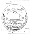
まず、遊技機の一例であるパチンコ遊技機1の全体の構成について説明する。図1はパチンコ遊技機1を正面から見た正面図、図2は遊技盤の前面を示す正面図である。
[First Embodiment]
First, the overall configuration of a pachinko gaming machine 1 that is an example of a gaming machine will be described. FIG. 1 is a front view of the pachinko gaming machine 1 as seen from the front, and FIG. 2 is a front view showing the front of the game board.

パチンコ遊技機1は、遊技場(遊技店)に設置される。遊技場内には遊技機が複数台並べて配置されている遊技機設置島が複数設けられており、パチンコ遊技機1は、そのような遊技機設置島に設置される。パチンコ遊技機1は、縦長の方形状に形成された外枠(図示せず)と、外枠の内側に開閉可能に取付けられた遊技枠とで構成される。図1に示すように、パチンコ遊技機1は、遊技枠に開閉可能に設けられている額縁状に形成されたガラス扉枠2を有する。遊技枠は、外枠に対して開閉自在に設置される前面枠(図示せず)と、機構部品等が取付けられる機構板と、それらに取付けられる種々の部品(後述する遊技盤を除く。)とを含む構造体である。   The pachinko gaming machine 1 is installed in a game hall (game shop). A plurality of gaming machine installation islands in which a plurality of gaming machines are arranged side by side are provided in the game hall, and the pachinko gaming machine 1 is installed on such a gaming machine installation island. The pachinko gaming machine 1 includes an outer frame (not shown) formed in a vertically long rectangular shape and a game frame attached to the inside of the outer frame so as to be openable and closable. As shown in FIG. 1, a pachinko gaming machine 1 has a glass door frame 2 formed in a frame shape that is provided in a game frame so as to be opened and closed. The game frame includes a front frame (not shown) installed to be openable and closable with respect to the outer frame, a mechanism plate to which mechanism parts and the like are attached, and various parts attached to them (excluding a game board described later). Is a structure including

ガラス扉枠2の下部表面には打球供給皿(上皿)3がある。打球供給皿3の下部には、打球供給皿3に収容しきれない遊技球を貯留する余剰球受皿4と遊技球を発射する打球操作ハンドル(操作ノブ)5が設けられている。また、打球操作ハンドル5の上方には、遊技中に遊技者が操作するための操作ボタン120が設けられている。操作ボタン120は、押しボタン式のプッシュスイッチであって、手で押すとオン状態となり、手を離すとオフ状態となるモーメンタリスイッチである。また、ガラス扉枠2の背面には、遊技盤6が着脱可能に取付けられている。なお、遊技盤6は、それを構成する板状体と、その板状体に取付けられた種々の部品とを含む構造体である。また、遊技盤6の前面には、打込まれた遊技球が流下可能な遊技領域7が形成されている。   On the lower surface of the glass door frame 2 is a hitting ball supply tray (upper plate) 3. Under the hitting ball supply tray 3, an extra ball receiving tray 4 for storing game balls that cannot be accommodated in the hit ball supply tray 3 and a hitting operation handle (operation knob) 5 for launching the game balls are provided. Further, an operation button 120 is provided above the hitting operation handle 5 for the player to operate during the game. The operation button 120 is a push button type push switch, and is a momentary switch that is turned on when pressed with a hand and turned off when released. A game board 6 is detachably attached to the back surface of the glass door frame 2. The game board 6 is a structure including a plate-like body constituting the game board 6 and various components attached to the plate-like body. In addition, a game area 7 is formed on the front surface of the game board 6 in which a game ball that has been struck can flow down.

遊技領域7の中央付近には、それぞれが演出用の飾り図柄を変動表示(可変表示または更新表示ともいう)する複数の変動表示領域を含み、所定の始動条件の成立(たとえば、打球が始動入賞口14に入賞したこと)に基づいて各々を識別可能な複数種類の演出用の飾り図柄を変動表示し表示結果を導出表示する変動表示装置9が配置されている。この実施の形態では、変動表示装置9は液晶表示装置(LCD)により構成され、左・中・右の3つの表示領域(飾り図柄表示エリア)に飾り図柄が表示制御されるように構成されている。なお、入賞とは、入賞口等の予め入賞領域として定められている領域に遊技球が入ったことである。また、表示結果を導出表示するとは、図柄の変動表示を開始してから所定の変動時間が経過したときに図柄を停止表示させることである(いわゆる再変動の前の仮停止を除く。)。   Near the center of the game area 7 includes a plurality of variable display areas, each of which displays a decorative design for presentation in a variable manner (also referred to as variable display or update display). A variation display device 9 is provided for variably displaying a plurality of types of decorative designs for presentations that can be identified based on the winning of the mouth 14) and for deriving and displaying the display results. In this embodiment, the variable display device 9 is configured by a liquid crystal display device (LCD), and is configured such that decorative symbols are displayed and controlled in three display areas (decorative symbol display areas) of left, middle, and right. Yes. Note that winning means that a game ball has entered a predetermined area such as a winning opening. Deriving and displaying the display result means that the symbol is stopped and displayed when a predetermined variation time has elapsed since the symbol variation display is started (except for the temporary stop before the so-called re-variation).

この実施の形態では、変動表示装置9の3つの表示領域に表示される飾り図柄として、「0」〜「9」の数字の図柄を用いている。飾り図柄の変動表示(変動)中、「0」〜「9」の飾り図柄が番号順に表示される。   In this embodiment, the symbols of numbers “0” to “9” are used as the decorative symbols displayed in the three display areas of the variable display device 9. During the decorative pattern variation display (variation), “0” to “9” decorative symbols are displayed in numerical order.

変動表示装置9の上部には、識別情報としての特別図柄を変動表示する特別図柄表示器(特別図柄表示装置)8が設けられている。この実施の形態では、特別図柄表示器8は、たとえば「0」〜「99」の数字を可変表示可能な簡易で小型の表示器(たとえば7セグメントLED)で実現されている。なお、特別図柄表示器8は、より簡易化した「0」〜「9」等の数字を可変表示するように構成されていてもよい。特別図柄表示器8は表示部が小型であるので、変動表示の態様および変動表示の表示結果が変動表示装置9と比べて見づらいため、遊技者は主として変動表示装置9の方に注目する。   A special symbol display (special symbol display device) 8 that variably displays a special symbol as identification information is provided on the top of the variable display device 9. In this embodiment, the special symbol display 8 is realized by a simple and small display (for example, 7 segment LED) capable of variably displaying numbers “0” to “99”, for example. The special symbol display 8 may be configured to variably display numbers such as “0” to “9” which are simplified. Since the display portion of the special symbol display 8 is small, the variation display mode and the display result of the variation display are difficult to see compared with the variation display device 9, so the player mainly pays attention to the variation display device 9.

変動表示装置9は、特別図柄表示器8による特別図柄の変動表示期間中に、装飾用(演出用)の図柄としての飾り図柄の変動表示を行なう。飾り図柄の変動表示を行なう変動表示装置9は、演出制御基板に搭載されている演出制御用マイクロコンピュータ100(図4参照)によって制御される。特別図柄の変動表示を行なう特別図柄表示器8は、遊技制御基板に搭載されている遊技制御用マイクロコンピュータ560(図4参照)によって制御される。   The variation display device 9 performs a variation display of a decorative symbol as a symbol for decoration (production) during the variation display period of the special symbol by the special symbol indicator 8. The variation display device 9 that performs variation display of decorative symbols is controlled by an effect control microcomputer 100 (see FIG. 4) mounted on the effect control board. The special symbol display 8 for displaying the variation of the special symbol is controlled by a game control microcomputer 560 (see FIG. 4) mounted on the game control board.

なお、本実施の形態においては、変動表示装置9は、液晶表示装置を用いた例について説明するが、これに限らず、変動表示装置9は、CRT(Cathode Ray Tube)、FED(Field Emission Display)、PDP(Plasma Display Panel)、ドットマトリクス、7セグメントLED等のLED(Light Emitting Diode)、エレクトロルミネッセンス、蛍光表示管等のその他の画像表示式の表示装置により構成されてもよい。また、変動表示装置9は、回転ドラム式表示装置等の機械式の表示装置であってもよい。   In the present embodiment, an example in which the variable display device 9 uses a liquid crystal display device will be described. However, the present invention is not limited to this, and the variable display device 9 may be a CRT (Cathode Ray Tube) or FED (Field Emission Display). ), PDP (Plasma Display Panel), dot matrix, LED (Light Emitting Diode) such as 7-segment LED, electroluminescence, and other image display type display devices such as a fluorescent display tube. The fluctuation display device 9 may be a mechanical display device such as a rotary drum display device.

変動表示装置9の下部には、始動入賞口14に入った有効入賞球数の記憶数すなわち保留記憶(始動記憶または始動入賞記憶ともいう。)数を表示する4つの表示器からなる特別図柄保留記憶表示器18が設けられている。有効始動入賞がある毎に、1つの表示器の表示色を変化させる。そして、特別図柄表示器8の変動表示が開始される毎に、1つの表示器の表示色を元に戻す。この例では、特別図柄表示器8と特別図柄保留記憶表示器18とが別個に設けられているので、変動表示中も保留記憶数が表示された状態にすることができる。なお、変動表示装置9の表示領域内に、保留記憶数を表示する4つの表示領域からなる特別図柄保留記憶表示領域を設けるようにしてもよい。また、この実施の形態では、保留記憶数の上限値を4とするが、上限値をより大きい値にしてもよい。さらに、上限値を、遊技状態に応じて変更可能であるようにしてもよい。   At the bottom of the variable display device 9, a special symbol hold comprising four indicators for displaying the number of effective winning balls entered into the start winning opening 14, that is, the number of hold memories (also referred to as start memory or start prize memory). A storage indicator 18 is provided. Every time there is an effective start prize, the display color of one display is changed. Then, every time the variable display of the special symbol display 8 is started, the display color of one display is restored. In this example, since the special symbol display 8 and the special symbol hold memory display 18 are provided separately, the number of hold memories can be displayed even during the variable display. In the display area of the variable display device 9, a special symbol reserved storage display area including four display areas for displaying the number of reserved memories may be provided. Further, in this embodiment, the upper limit value of the number of reserved memories is 4, but the upper limit value may be a larger value. Further, the upper limit value may be changed according to the gaming state.

変動表示装置9の下方には、始動入賞口14を有する可変入賞球装置15が設けられている。可変入賞球装置15には、開閉動作をすることが可能な態様で左右一対の可動片が設けられている。可変入賞球装置15の可動片は、後述する開放条件が成立したときに、ソレノイド16によって駆動されて所定期間開状態とされる。可変入賞球装置15の可動片が開状態となることにより、遊技球が始動入賞口14に入賞し易くなり(始動入賞し易くなり)、遊技者にとって有利な状態(第1の状態)となる。一方、可変入賞球装置15の可動片が閉状態となることにより、遊技球が始動入賞口14に入賞しにくくなり(始動入賞しにくくなり)、遊技者にとって不利な状態(第2の状態)となる。始動入賞口14に入った入賞球は、遊技盤6の背面に導かれ、始動口スイッチ14aによって検出される。   Below the variable display device 9, a variable winning ball device 15 having a start winning port 14 is provided. The variable winning ball apparatus 15 is provided with a pair of left and right movable pieces in such a manner that it can be opened and closed. The movable piece of the variable winning ball device 15 is driven by the solenoid 16 to be in an open state for a predetermined period when an opening condition described later is satisfied. When the movable piece of the variable winning ball device 15 is in the open state, it becomes easy for the game ball to win the start winning opening 14 (easy to start winning), and the player is in an advantageous state (first state). . On the other hand, when the movable piece of the variable winning ball device 15 is in the closed state, it becomes difficult for the game ball to win the start winning opening 14 (it is difficult to start winning), which is disadvantageous for the player (second state). It becomes. The winning ball that has entered the start winning opening 14 is guided to the back of the game board 6 and detected by the start opening switch 14a.

可変入賞球装置15の下部には、特別図柄表示器8に特定表示結果(大当り図柄:たとえば「−−」以外の「00」〜「99」の図柄)が導出表示された場合に生起する特定遊技状態(大当り遊技状態)においてソレノイド21によって開閉される開閉板20aを用いた特別可変入賞球装置20が設けられている。特別可変入賞球装置20は、開閉板20aによって開閉される大入賞口が設けられており、大当り遊技状態において開閉板20aが遊技者にとって有利な開状態(第1の状態)に制御され、大当り遊技状態以外の状態において開閉板が遊技者にとって不利な閉状態(第2の状態)に制御される。このように、特別可変入賞球装置20は、大当り遊技状態となるときに開放条件が成立する。特別可変入賞球装置20に入賞し遊技盤6の背面に導かれた入賞球のうち一方(V入賞領域:特別領域)に入った入賞球はV入賞スイッチ22で検出された後カウントスイッチ23で検出され、他方の領域に入った遊技球は、そのままカウントスイッチ23で検出される。遊技盤6の背面には、大入賞口内の経路を切換えるためのソレノイド21Aも設けられている。   A specific occurrence that occurs when a specific display result (a jackpot symbol: for example, symbols “00” to “99” other than “-”) is derived and displayed on the special symbol display 8 below the variable winning ball apparatus 15. A special variable winning ball apparatus 20 using an opening / closing plate 20a that is opened and closed by a solenoid 21 in a gaming state (a big hit gaming state) is provided. The special variable winning ball apparatus 20 is provided with a large winning opening that is opened and closed by an opening / closing plate 20a. In the big hit game state, the open / close plate 20a is controlled to an open state (first state) advantageous to the player, and the big hit In a state other than the gaming state, the open / close plate is controlled to a closed state (second state) that is disadvantageous to the player. As described above, the special variable winning ball apparatus 20 satisfies the release condition when it enters the big hit gaming state. Of the winning balls that are won in the special variable winning ball apparatus 20 and guided to the back of the game board 6, the winning ball that has entered one (V winning area: special area) is detected by the V winning switch 22 and then counted by the count switch 23. The game ball that has been detected and entered the other region is detected by the count switch 23 as it is. On the back of the game board 6, a solenoid 21A for switching the path in the special winning opening is also provided.

本実施の形態の場合は、大当りとして複数種類の大当りが設けられている。大当りには、通常大当り、確変大当り、および、突然確変大当りが設けられている。また、特別図柄の表示結果に応じて特定遊技状態となる当りには、大当りの他に、小当りも含まれている。なお、大当りのうち、確変大当りのときと通常大当りのときとで、特別図柄表示器8に異なる図柄を表示させるようにしてもよい。たとえば、確変大当りのときには特別図柄表示器8に「40」〜「79」の図柄を表示させるようにし、通常大当りのときには特別図柄表示器8に「00」〜「39」の図柄を表示させるようにしてもよい。また、確変大当りのときと通常大当りのときとで、特別図柄表示器8に同じ図柄を表示させるようにしてもよい。たとえば、確変大当りまたは通常大当りのいずれの場合であっても、特別図柄表示器8に「00」〜「79」の図柄を表示させるようにしてもよい。また、突然確変大当りのときと小当りのときとで特別図柄表示器8に同じ図柄(たとえば、「80」〜「99」)を表示させるようにしてもよく、異なる図柄を表示させるようにしてもよい。   In the case of the present embodiment, multiple types of big hits are provided as big hits. The big hit is usually a big hit, a probabilistic big hit, and a sudden probable big hit. In addition, in addition to big hits, small wins are included in the hits that result in a specific gaming state according to the display result of the special symbol. It should be noted that, among the big hits, different symbols may be displayed on the special symbol display 8 depending on whether the probability big hit or the normal big hit. For example, the special symbol display 8 displays the symbols “40” to “79” when the probability big hit, and the special symbol display 8 displays the symbols “00” to “39” when the big hit is normal. It may be. In addition, the same symbol may be displayed on the special symbol display 8 at the probability variation big hit and the normal big hit. For example, the symbols “00” to “79” may be displayed on the special symbol display 8 regardless of whether the probability variation big hit or the normal big hit. Further, the same symbol (for example, “80” to “99”) may be displayed on the special symbol display 8 for sudden probability big hit and small hit, or different symbols may be displayed. Also good.

変動表示装置9の真上には、普通図柄表示器10が設けられている。普通図柄表示器10は、普通図柄と呼ばれる複数種類の識別情報(たとえば、「○」および「×」)を変動表示する。   A normal symbol display 10 is provided directly above the fluctuation display device 9. The normal symbol display 10 variably displays a plurality of types of identification information called “normal symbols” (for example, “◯” and “x”).

ゲート32に遊技球が入賞しゲートスイッチ32aで検出されると、普通図柄表示器10の表示の変動表示が開始される。この実施の形態では、左右のランプ(点灯時に図柄が視認可能になる)が交互に点灯することによって変動表示が行なわれ、たとえば、変動表示の終了時に左側のランプが点灯すれば当りとなる。そして、普通図柄表示器10における停止図柄が所定の図柄(当り図柄)である場合に、可変入賞球装置15が所定回数、所定時間だけ開状態になる。すなわち、可変入賞球装置15の状態は、普通図柄の停止図柄が当り図柄である場合に、遊技者にとって不利な状態から有利な状態に変化する。普通図柄表示器10の近傍には、ゲート32を通過した入賞球数を表示する4つのLEDによる表示部を有する普通図柄保留記憶表示器41が設けられている。ゲート32への遊技球の通過がある毎に、普通図柄保留記憶表示器41は点灯するLEDを1増やす。そして、普通図柄表示器10の変動表示が開始される毎に、点灯するLEDを1減らす。   When a game ball wins the gate 32 and is detected by the gate switch 32a, the display variation of the normal symbol display 10 is started. In this embodiment, the left and right lamps (the symbols can be visually recognized at the time of lighting) are alternately turned on to perform the variable display. For example, if the left lamp is turned on at the end of the variable display, it is a hit. When the stop symbol on the normal symbol display 10 is a predetermined symbol (winning symbol), the variable winning ball device 15 is opened for a predetermined number of times. That is, the state of the variable winning ball device 15 changes from a disadvantageous state to a player's advantageous state when the normal symbol is a winning symbol. In the vicinity of the normal symbol display 10, a normal symbol holding storage display 41 having a display unit with four LEDs for displaying the number of winning balls that have passed through the gate 32 is provided. Each time there is a game ball passing to the gate 32, the normal symbol hold memory display 41 increments the LED to be turned on by one. Then, each time the variable display of the normal symbol display 10 is started, the number of LEDs to be lit is reduced by one.

遊技盤6には、複数の入賞口29,30,33,39が設けられ、遊技球の入賞口29,30,33,39への入賞は、それぞれ入賞口スイッチ29a,30a,33a,39aによって検出される。各入賞口29,30,33,39は、遊技球を受け入れて入賞を許容する領域として遊技盤6に設けられる入賞領域を構成している。なお、始動入賞口14や大入賞口も、遊技球を受け入れて入賞を許容する入賞領域を構成する。遊技盤6の遊技領域7の左右周辺には、遊技中に点滅表示される装飾ランプ25が設けられ、下部には、入賞しなかった打球が取込まれるアウト口26がある。また、遊技領域7の外側の左右上部には、所定の音声出力として効果音や音声を発声する2つの音出力装置としてのスピーカ27が設けられている。遊技領域7の外周には、LEDよりなる天枠ランプ28a、左枠ランプ28bおよび右枠ランプ28cが設けられている。さらに、遊技領域7における各構造物(大入賞口等)の周囲には装飾LEDが設置されている。天枠ランプ28a、左枠ランプ28b、右枠ランプ28cおよび装飾用LEDは、パチンコ遊技機1に設けられている装飾発光体の一例である。   The game board 6 is provided with a plurality of winning holes 29, 30, 33, 39, and winning of game balls to the winning holes 29, 30, 33, 39 is performed by winning hole switches 29a, 30a, 33a, 39a, respectively. Detected. Each winning opening 29, 30, 33, 39 constitutes a winning area provided in the game board 6 as an area for accepting game balls and allowing winning. The start winning opening 14 and the big winning opening also constitute a winning area that accepts game balls and allows winning. A decorative lamp 25 blinkingly displayed during the game is provided around the left and right sides of the game area 7 of the game board 6, and an outlet 26 for receiving a hit ball that has not won a prize is provided below. In addition, speakers 27 as two sound output devices that utter sound effects and sounds as predetermined sound outputs are provided on the left and right upper portions outside the game area 7. On the outer periphery of the game area 7, a top frame lamp 28a, a left frame lamp 28b, and a right frame lamp 28c made of LEDs are provided. Further, a decoration LED is installed around each structure (such as a big prize opening) in the game area 7. The top frame lamp 28a, the left frame lamp 28b, the right frame lamp 28c, and the decoration LED are examples of a decorative light emitter provided in the pachinko gaming machine 1.

そして、この例では、左枠ランプ28bの近傍に、賞球払出中に点灯するLEDよりなる賞球ランプ51が設けられ、右枠ランプ28cの近傍に、補給球が切れたときに点灯するLEDよりなる球切れランプ52が設けられている。さらに、プリペイドカードが挿入されることによって球貸しを可能にするプリペイドカードユニット(以下、「カードユニット」という。)50が、パチンコ遊技機1に隣接して設置されている。賞球ランプ51、球切れランプ52、装飾ランプ25、天枠ランプ28a、左枠ランプ28bおよび右枠ランプ28c等の各種発光手段は、後述するランプドライバ基板35によって点灯制御(ランプ制御)される。また、スピーカ27からの音発生制御(音制御)は、後述する音声出力基板70によって行なわれる。   In this example, a prize ball lamp 51 is provided in the vicinity of the left frame lamp 28b. The prize ball lamp 51 is an LED that is lit while paying out a prize ball. The LED that is lit when the supply ball is cut near the right frame lamp 28c. A ball break lamp 52 is provided. Further, a prepaid card unit (hereinafter referred to as “card unit”) 50 that enables lending a ball by inserting a prepaid card is installed adjacent to the pachinko gaming machine 1. Various light emitting means such as a prize ball lamp 51, a ball break lamp 52, a decoration lamp 25, a top frame lamp 28a, a left frame lamp 28b, and a right frame lamp 28c are controlled to be lit (lamp control) by a lamp driver board 35 described later. . Further, sound generation control (sound control) from the speaker 27 is performed by an audio output board 70 described later.

カードユニット50には、たとえば、使用可能状態であるか否かを示す使用可表示ランプ、カードユニット50がいずれの側のパチンコ遊技機1に対応しているのかを示す連結台方向表示器、カードユニット50内にカードが投入されていることを示すカード投入表示ランプ、記録媒体としてのカードが挿入されるカード挿入口、および、カード挿入口の裏面に設けられているカードリーダライタの機構を点検する場合にカードユニット50を解放するためのカードユニット錠が設けられている。   The card unit 50 includes, for example, a usable display lamp that indicates whether or not the card unit 50 is in a usable state, a connected table direction indicator that indicates which side of the pachinko gaming machine 1 corresponds to the card unit 50, and a card. Check the card insertion indicator lamp indicating that a card has been inserted into the unit 50, the card insertion slot into which a card as a recording medium is inserted, and the mechanism of the card reader / writer provided on the back of the card insertion slot. A card unit lock is provided for releasing the card unit 50 in the case of doing so.

パチンコ遊技機1には、遊技者が打球操作ハンドル5を操作することに応じて駆動モータを駆動し、駆動モータの回転力を利用して遊技球を遊技領域7に発射する打球発射装置(図示せず)が設けられている。打球発射装置から発射された遊技球は、遊技領域7を囲むように円形状に形成された打球レールを通って遊技領域7に入り、その後、遊技領域7を下りてくる。遊技球が始動入賞口14に入り始動口スイッチ14aで検出されると、特別図柄の変動表示を開始できる状態であれば(たとえば、大当り遊技終了または前回の変動表示の終了)、特別図柄表示器8において特別図柄の変動表示(変動)が開始されるとともに、変動表示装置9において飾り図柄の変動表示が開始される。特別図柄の変動表示を開始できる状態でなければ、特別図柄保留記憶表示器18についての保留記憶数を1増やす。   The pachinko gaming machine 1 has a ball striking device for driving a driving motor in response to the player operating the ball striking operation handle 5, and using the rotational force of the driving motor to launch the game ball to the game area 7 (see FIG. Not shown). A game ball launched from the ball striking device enters the game area 7 through a ball striking rail formed in a circular shape so as to surround the game area 7, and then descends the game area 7. If the game ball enters the start winning opening 14 and is detected by the start opening switch 14a, the special symbol indicator is displayed if the variation display of the special symbol can be started (for example, end of the big hit game or end of the previous variation display) In 8, the special symbol variation display (variation) is started, and in the variation display device 9, the decorative symbol variation display is started. If the special symbol variation display cannot be started, the reserved memory number for the special symbol storage memory indicator 18 is increased by one.

特別図柄表示器8における特別図柄および変動表示装置9の飾り図柄の変動表示は、所定時間が経過したときに停止する。停止時の停止図柄が大当り図柄(特定表示結果)になると、大当り遊技状態に移行する。すなわち、遊技状態が大当り遊技状態以外の通常状態のときと比較して遊技者にとって有利な特定遊技状態に移行する。特定遊技状態(大当り遊技状態)では、一定時間(たとえば29.5秒)が経過するまで、または、所定個数(たとえば、10個)の遊技球が大入賞口に入賞するまで特別可変入賞装置が開放される。なお、特別可変入賞装置が開放されてから一定期間経過するまで、または、所定個数(たとえば、10個)の打球が大入賞口に入賞するまでが大当り遊技状態における1ラウンドである。なお、この実施の形態では、大当り遊技状態を15ラウンド継続させる。   The variation display of the special symbol on the special symbol display 8 and the decorative symbol of the variation display device 9 stops when a predetermined time has elapsed. When the stop symbol at the time of stoppage becomes a jackpot symbol (specific display result), the game shifts to a jackpot game state. That is, the game state shifts to a specific game state that is advantageous to the player as compared to a normal state other than the big hit game state. In the specific game state (big hit game state), the special variable prize-winning device is used until a predetermined time (for example, 29.5 seconds) elapses or until a predetermined number (for example, 10) of game balls enter the big prize opening. Opened. It should be noted that one round in the big hit gaming state is from when the special variable winning device is opened until a certain period of time elapses or until a predetermined number (for example, 10) of hitting balls wins the big winning opening. In this embodiment, the big hit gaming state is continued for 15 rounds.

特別図柄表示器8における特別図柄の変動表示と、変動表示装置9における飾り図柄の変動表示とは同期している。ここで、同期とは、変動表示の期間が同じであることをいう。また、特別図柄表示器8において大当り図柄(たとえば「−−」以外の「00」〜「99」の図柄)が停止表示されるときには、変動表示装置9において左中右の飾り図柄が揃った状態(たとえば「222」や「777」等)で停止表示される。以下、変動表示装置9において左中右の飾り図柄が揃った状態で停止表示されることを、飾り図柄の大当り図柄(特定表示結果)が表示されるというように表現する。   The variation display of the special symbol on the special symbol display 8 and the variation display of the decorative symbol on the variation display device 9 are synchronized. Here, “synchronization” means that the variable display period is the same. In addition, when the special symbol display 8 stops the jackpot symbol (for example, symbols “00” to “99” other than “-”), the left, right and right decorative symbols are aligned on the variable display device 9. (For example, “222” or “777”) is stopped and displayed. Hereinafter, the fact that the left and right decorative symbols are aligned and displayed on the variable display device 9 is expressed as a big hit symbol (specific display result) of the decorative symbols being displayed.

変動表示装置9において左中右の奇数の飾り図柄(「1」「3」「5」「7」「9」)が揃った状態(たとえば「777」)で停止表示されたときは、大当り遊技状態に移行するとともに、大当り遊技状態の終了後に、大当りの判定を行なう際に通常遊技状態よりも高い確率(割合)で大当りと判定する遊技者にとって有利な特別遊技状態としての確変状態(確率変動状態のことをいい、高確率状態ともいう)に制御される。すなわち、変動表示装置9の表示結果が大当り図柄の表示結果のうちの特別な表示結果となったときには、確変状態という遊技者にとってさらに有利な状態になる。この実施の形態では、所定の移行条件が成立したときに遊技状態が確変状態に移行される。具体的には、内部的に確変とすることが決定され、上記のように飾り図柄の変動表示の終了時に停止図柄として確変図柄を停止表示したとき(左中右の奇数の図柄が揃った状態で停止表示したとき、飾り図柄が「123」または「357」で停止表示したとき)、所定の移行条件が成立したとして確変状態に移行される。   When the variable display device 9 is stopped and displayed in the state where the odd left and right decorative symbols (“1” “3” “5” “7” “9”) are aligned (for example, “777”), the big hit game When the jackpot game state ends, the probability change state (probability fluctuation) as a special gaming state advantageous to the player who judges the jackpot with a higher probability (ratio) than the normal gaming state when the jackpot determination is made It is a state, also called a high probability state). That is, when the display result of the variable display device 9 becomes a special display result of the display results of the jackpot symbol, it becomes a more advantageous state for the player in the probable change state. In this embodiment, the gaming state is shifted to the probability changing state when a predetermined transition condition is satisfied. Specifically, it is determined that the probability is changed internally, and when the symbol change symbol is stopped as a stop symbol at the end of the decorative symbol variation display as described above (an odd number of symbols in the middle left and right are aligned) When the display is stopped and the decoration symbol is “123” or “357”, the transition is made to a certain change state as a predetermined transition condition is satisfied.

このように、「0」〜「9」の飾り図柄のうち、確変状態を生起させる奇数の飾り図柄のことを確変図柄といい、確変状態を生起させない偶数の飾り図柄のことを非確変図柄という。また、変動表示装置9において左中右の奇数の飾り図柄が揃った状態で停止表示されることを、飾り図柄の確変図柄(特別表示結果)が表示されるというように表現する。   As described above, among the decorative symbols “0” to “9”, an odd number of decorative symbols that cause a probability variation state is referred to as a probability variation symbol, and an even number of decorative symbols that do not cause a probability variation state is referred to as a non-probability variation symbol. . Further, the fact that the variable display device 9 is stopped and displayed in a state where the left, middle and right odd-numbered decorative symbols are aligned is expressed such that the probability variation symbol (special display result) of the decorative symbol is displayed.

この実施の形態では、確変大当りにすることが事前決定されているときに、高確率状態に移行するとともに、特別図柄および飾り図柄の変動時間を短縮する時短状態に移行するように制御する。その場合、確変フラグとは別に時短フラグをセットし、時短フラグに基づいて変動時間を短縮させればよい。また、突然確変大当りにすることが事前決定されているときには、高確率状態に移行するだけで時短状態には移行しないように制御する。なお、遊技状態を確変状態に移行する場合には、単に特別図柄や飾り図柄が大当り図柄となる確率を高めた高確率状態に移行するだけで、普通図柄が当り図柄となる確率や、可変入賞球装置15における開放時間や開放回数の状態を変化させず、普通図柄が当り図柄となる確率や、可変入賞球装置15における開放時間や開放回数の状態の変化は、時短状態(時短フラグがセットされた状態)に制御されていることに基づいて実行するようにすればよい。   In this embodiment, when it is predetermined to make a probable big hit, control is performed so as to shift to a high probability state and to shift to a short time state in which the variation time of the special symbol and the decorative symbol is shortened. In that case, it is only necessary to set a time reduction flag separately from the probability change flag and reduce the variation time based on the time reduction flag. In addition, when it is determined in advance that a sudden probability change big hit will be made, control is performed so that only the transition to the high probability state is performed, and the transition to the short time state is not performed. In addition, when changing the gaming state to the probable state, simply changing to a high probability state in which the probability that a special symbol or decorative symbol will be a big hit symbol is increased, the probability that a normal symbol will be a winning symbol, or a variable prize The probability that a normal symbol becomes a winning symbol without changing the state of the opening time and the number of times of opening in the ball device 15 and the change in the state of the opening time and the number of times of opening in the variable winning ball device 15 are set to the short time state (the short time flag is set). It is only necessary to execute the control based on the fact that the controlled state is controlled.

たとえば、通常大当りや突然確変大当りを除く確変大当りである場合には、遊技状態を高確率状態に移行するとともに、遊技球が始動入賞しやすくなる(すなわち、特別図柄表示装置8や変動表示装置9における変動表示の実行条件が成立しやすくなる)ように制御された遊技状態である高ベース状態に移行する。高ベース状態である場合には、たとえば、高ベース状態でない場合と比較して、可変入賞球装置15が開状態となる頻度が高められたり、可変入賞球装置15が開状態となる時間が延長されたりして、始動入賞しやすくなる。   For example, in the case of a probabilistic big hit excluding a normal big hit or a sudden probable big hit, the game state is shifted to a high probability state, and the game ball is likely to start and win (that is, the special symbol display device 8 and the variable display device 9). The transition to the high base state, which is a gaming state controlled so that the execution condition of the variable display in (is easily established). In the high base state, for example, the frequency at which the variable winning ball device 15 is opened or the time during which the variable winning ball device 15 is in the open state is increased as compared to the case where the high base state is not set. It becomes easier to win a start.

なお、可変入賞球装置15が開状態となる時間を延長する(開放延長状態ともいう)のでなく、普通図柄表示器10における停止図柄が当り図柄になる確率が高められる普通図柄確変状態に移行することによって、高ベース状態に移行してもよい。普通図柄表示器10における停止図柄が所定の図柄(当り図柄)となると、可変入賞球装置15が所定回数、所定時間だけ開状態になる。この場合、普通図柄確変状態に移行制御することによって、普通図柄表示器10における停止図柄が当り図柄になる確率が高められ、可変入賞球装置15が開状態となる頻度が高まる。したがって、普通図柄確変状態に移行すれば、可変入賞球装置15の開放時間と開放回数が高められ、始動入賞しやすい状態(高ベース状態)となる。すなわち、可変入賞球装置15の開放時間と開放回数は、普通図柄の停止図柄が当り図柄であったり、特別図柄の停止図柄が確変図柄である場合等に高められ、遊技者にとって不利な状態から有利な状態(始動入賞しやすい状態)に変化する。なお、開放回数が高められることは、閉状態から開状態になることも含む概念である。   Instead of extending the time during which the variable winning ball apparatus 15 is in the open state (also referred to as the open extended state), the normal symbol display unit 10 shifts to a normal symbol probability changing state in which the probability that the stop symbol in the normal symbol display unit 10 is a hit symbol is increased. Depending on the situation, the high base state may be entered. When the stop symbol in the normal symbol display 10 becomes a predetermined symbol (winning symbol), the variable winning ball device 15 is opened for a predetermined number of times. In this case, by performing the transition control to the normal symbol probability changing state, the probability that the stop symbol in the normal symbol display 10 becomes a winning symbol is increased, and the frequency at which the variable winning ball apparatus 15 is opened is increased. Therefore, if the normal symbol probability changing state is entered, the opening time and the number of opening times of the variable winning ball apparatus 15 are increased, and a state in which a start winning is easily made (high base state) is achieved. That is, the opening time and the number of times of opening of the variable winning ball device 15 can be increased when the stop symbol of the normal symbol is a winning symbol or the stop symbol of the special symbol is a probabilistic symbol. It changes to an advantageous state (a state where it is easy to win a start). It should be noted that increasing the number of times of opening is a concept including changing from a closed state to an open state.

また、普通図柄表示器10における普通図柄の変動時間(変動表示期間)が短縮される普通図柄時短状態に移行することによって、高ベース状態に移行してもよい。普通図柄時短状態では、普通図柄の変動時間が短縮されるので、普通図柄の変動が開始される頻度が高くなり、結果として普通図柄が当りとなる頻度が高くなる。したがって、普通図柄が当りとなる頻度が高くなることによって、可変入賞球装置15が開状態となる頻度が高くなり、始動入賞しやすい状態(高ベース状態)となる。   Moreover, you may transfer to a high base state by shifting to the normal symbol time-short state where the fluctuation time (variation display period) of the normal symbol in the normal symbol display 10 is shortened. In the normal symbol short-time state, the variation time of the normal symbol is shortened, so that the frequency of starting the variation of the normal symbol increases, and as a result, the frequency of hitting the normal symbol increases. Therefore, when the frequency that the normal symbol is hit increases, the frequency that the variable winning ball apparatus 15 is opened is increased, and the start winning state is easily set (high base state).

また、特別図柄や飾り図柄の変動時間(変動表示期間)が短縮される特別図柄時短状態に移行することによって、高ベース状態に移行してもよい。特別図柄時短状態では、特別図柄や飾り図柄の変動時間が短縮されるので、特別図柄や飾り図柄の変動が開始される頻度が高くなり(換言すれば、保留記憶の消化が速くなる。)、結果として、始動入賞しやすくなり(高ベース状態に移行し)大当り遊技が行なわれる可能性が高まる。   Moreover, you may transfer to a high base state by shifting to the special symbol time-short state where the variation time (variable display period) of the special symbol or decorative symbol is shortened. In the special symbol short-time state, the variation time of the special symbol or the decorative symbol is shortened, so that the frequency of starting the variation of the special symbol or the decorative symbol is increased (in other words, the digestion of the reserved memory is accelerated). As a result, it becomes easier to win a start (transition to a high base state), and the possibility that a big hit game is performed increases.

さらに、上記に示した全ての状態(開放延長状態、普通図柄確変状態、普通図柄時短状態および特別図柄時短状態)に移行させることによって、始動入賞しやすくなる(高ベース状態に移行する)ようにしてもよい。また、上記に示した各状態(開放延長状態、普通図柄確変状態、普通図柄時短状態および特別図柄時短状態)のうちのいずれか複数の状態に移行させることによって、始動入賞しやすくなる(高ベース状態に移行する)ようにしてもよい。   Furthermore, by making transitions to all the states shown above (open extended state, normal symbol probability change state, normal symbol short time state, and special symbol short time state), it will be easier to win a start (shift to a high base state). May be. In addition, it is easier to win a start (high base) by shifting to any one of the above states (open extended state, normal symbol probability changing state, normal symbol short time state, and special symbol short time state). Transition to a state).

次に、リーチ表示態様(リーチ)について説明する。この実施の形態におけるリーチ表示態様(リーチ)とは、停止した飾り図柄が大当り図柄の一部を構成しているときに未だ停止していない飾り図柄については変動表示(変動表示)が行なわれていること、および、全てまたは一部の飾り図柄が大当り図柄の全てまたは一部を構成しながら同期して変動表示している状態である。   Next, the reach display mode (reach) will be described. In this embodiment, the reach display mode (reach) means that the decorative symbols that have not been stopped when the stopped decorative symbols constitute a part of the jackpot symbol are displayed in a variable manner (variable display). And all or part of the decorative symbols are in a state of being variably displayed synchronously while constituting all or part of the jackpot symbol.

たとえば、変動表示装置9における左、中、右の表示領域のうち左、右の表示領域には大当り図柄の一部になる飾り図柄(たとえば、「7」)が停止表示されている状態で中の表示領域は未だ変動表示が行なわれている状態、および表示領域の全てまたは一部の図柄が大当り図柄の全てまたは一部を構成しながら同期して変動表示している状態(たとえば、変動表示装置9における左、中、右の表示領域の全てに変動表示が行なわれ、常に同一の図柄が揃っている状態で変動表示が行なわれている状態)がリーチ表示態様またはリーチになる。   For example, a decorative symbol (for example, “7”) that becomes a part of the big hit symbol is stopped and displayed in the left and right display regions among the left, middle, and right display regions in the variable display device 9. The display area of the display area is still in a variable display state, and all or a part of the display area is in a variable display while forming all or a part of the jackpot symbol (for example, a variable display) The variable display is performed on all of the left, middle, and right display areas in the device 9, and the variable display is always performed in a state where the same symbols are aligned.

また、リーチの際に、通常と異なる演出がランプや音で行なわれる。その演出と変動表示装置9におけるリーチ表示態様とをリーチ演出という。また、リーチの際に、キャラクタ(人物等を模した演出表示であり、図柄(飾り図柄等)とは異なるもの)を表示させたり、変動表示装置9の背景の表示態様(たとえば、色等)を変化させたりすることがある。   In addition, during the reach, an unusual performance is performed with a lamp or sound. The effect and the reach display mode in the fluctuation display device 9 are called reach effects. Further, in the case of reach, a character (an effect display imitating a person or the like, which is different from a design (decorative design etc.)) or a background display mode (for example, color) of the variable display device 9 is displayed. May be changed.

次に、パチンコ遊技機1の裏面の構造について図3を参照して説明する。図3は、パチンコ遊技機1を裏面から見た背面図である。   Next, the structure of the back surface of the pachinko gaming machine 1 will be described with reference to FIG. FIG. 3 is a rear view of the pachinko gaming machine 1 as seen from the back side.

図3に示すように、パチンコ遊技機1裏面側では、変動表示装置9を制御する演出制御用マイクロコンピュータが搭載された演出制御基板80を含む変動表示制御ユニット49、遊技制御用マイクロコンピュータ等が搭載された遊技制御基板(主基板)31、音声出力基板70、ランプドライバ基板35、および、球払出制御を行なう払出制御用マイクロコンピュータ等が搭載された払出制御基板37等の各種基板が設置されている。   As shown in FIG. 3, on the back side of the pachinko gaming machine 1, there are a variable display control unit 49 including an effect control board 80 on which an effect control microcomputer for controlling the variable display device 9 is mounted, a game control microcomputer, and the like. Various boards such as a mounted game control board (main board) 31, an audio output board 70, a lamp driver board 35, and a payout control board 37 on which a payout control microcomputer for performing ball payout control are mounted are installed. ing.

さらに、パチンコ遊技機1裏面側には、DC30V、DC21V、DC12VおよびDC5V等の各種電源電圧を作成する電源回路が搭載された電源基板910やタッチセンサ基板91Aが設けられている。電源基板910は、大部分が主基板31と重なっているが、主基板31に重なることなく外部から視認可能に露出した露出部分がある。この露出部分には、パチンコ遊技機1における主基板31および各電気部品制御基板(演出制御基板80、払出制御基板37、音声出力基板70、および、ランプドライバ基板35)やパチンコ遊技機1に設けられている各電気部品(電力が供給されることによって動作する部品)への電力供給を実行あるいは遮断するための電力供給許可手段としての電源スイッチ911と、遊技制御用マイクロコンピュータ等のマイクロコンピュータのRAMの記憶情報をクリアすることを指示するためのクリアスイッチ912とが設けられている。クリアスイッチ912は、押しボタン式のプッシュスイッチであって、手で押すとオン状態となり、手を離すとオフ状態となるモーメンタリスイッチである。電源スイッチ911と、クリアスイッチ912とのそれぞれは、パチンコ遊技機1の裏面側に設けられているので、遊技場の店員が操作することができるが、遊技者は操作することができない操作手段である。また、露出部分における電源スイッチ911の内側(基板内部側)には、交換可能なヒューズが設けられている。   Further, on the back side of the pachinko gaming machine 1, a power supply substrate 910 and a touch sensor substrate 91A on which power supply circuits for generating various power supply voltages such as DC30V, DC21V, DC12V, and DC5V are mounted. Although most of the power supply substrate 910 overlaps with the main substrate 31, there is an exposed portion that is exposed so as to be visible from the outside without overlapping the main substrate 31. The exposed portion is provided on the main board 31 and each electrical component control board (production control board 80, payout control board 37, audio output board 70, and lamp driver board 35) in the pachinko gaming machine 1 or the pachinko gaming machine 1. A power switch 911 as a power supply permission means for executing or shutting off power supply to each of the electric components (components that operate when power is supplied), and a microcomputer such as a game control microcomputer A clear switch 912 for instructing to clear the stored information in the RAM is provided. The clear switch 912 is a push button type push switch, and is a momentary switch that is turned on when the hand is pressed and turned off when the hand is released. Each of the power switch 911 and the clear switch 912 is provided on the back side of the pachinko gaming machine 1, so that it can be operated by a store clerk in the game hall, but the player cannot operate it. is there. A replaceable fuse is provided inside the power switch 911 in the exposed portion (on the inside of the board).

また、ランプドライバ基板35には、後述するような演出に関する情報等の各種の情報を設定するための演出スイッチ354が設けられている。演出スイッチ354は、押しボタン式のプッシュスイッチであって、手で押すとオン状態となり、手を離すとオフ状態となるモーメンタリスイッチである。このような演出スイッチ354は、パチンコ遊技機1の裏面側に設けられているので、遊技場の店員が操作することができるが、遊技者は操作することができない操作手段である。   In addition, the lamp driver board 35 is provided with an effect switch 354 for setting various types of information such as information relating to effects as described later. The effect switch 354 is a push button type push switch, and is a momentary switch that is turned on when pressed with a hand and turned off when released. Since such an effect switch 354 is provided on the back side of the pachinko gaming machine 1, it can be operated by a store clerk in the game hall, but cannot be operated by the player.

なお、電気部品制御基板には、電気部品制御用マイクロコンピュータを含む電気部品制御手段が搭載されている。電気部品制御手段は、遊技制御手段等からのコマンドとしての指令信号(制御信号)にしたがってパチンコ遊技機1に設けられている電気部品(遊技用装置:球払出装置97、変動表示装置9、ランプやLEDなどの発光体、スピーカ27等)を制御する。以下、主基板31を電気部品制御基板に含めて説明を行なうことがある。その場合には、電気部品制御基板に搭載される電気部品制御手段は、遊技制御手段と、遊技制御手段等からの指令信号にしたがってパチンコ遊技機1に設けられている電気部品を制御する手段とのそれぞれを指す。また、主基板31以外のマイクロコンピュータが搭載された基板をサブ基板ということがある。   An electrical component control means including an electrical component control microcomputer is mounted on the electrical component control board. The electrical component control means is an electrical component (game device: ball payout device 97, variable display device 9, lamp) provided in the pachinko gaming machine 1 in accordance with a command signal (control signal) as a command from the game control means or the like. And light emitters such as LEDs, speakers 27, etc.). Hereinafter, description may be made by including the main board 31 in the electric component control board. In that case, the electrical component control means mounted on the electrical component control board includes a game control means and means for controlling the electrical components provided in the pachinko gaming machine 1 in accordance with a command signal from the game control means and the like. Each of them. A substrate on which a microcomputer other than the main substrate 31 is mounted may be referred to as a sub-substrate.

パチンコ遊技機1裏面において、上方には、各種情報をパチンコ遊技機1外部に出力するための各端子を備えたターミナル基板160が設置されている。ターミナル基板160には、少なくとも、球切れ検出スイッチ167の出力を導入して外部出力するための球切れ用端子、賞球情報(賞球個数信号)を外部出力するための賞球用端子および球貸し情報(球貸し個数信号)を外部出力するための球貸し用端子が設けられている。また、中央付近には、主基板31からの各種情報をパチンコ遊技機1外部に出力するための各端子を備えた情報端子基板(情報出力基板)36が設置されている。   On the back side of the pachinko gaming machine 1, a terminal board 160 having terminals for outputting various information to the outside of the pachinko gaming machine 1 is installed above. The terminal board 160 includes at least a ball break terminal for introducing the output of the ball break detection switch 167 and outputting it externally, a prize ball terminal for outputting prize ball information (prize ball number signal) and a ball. A ball lending terminal for externally outputting lending information (ball lending number signal) is provided. Near the center, an information terminal board (information output board) 36 provided with terminals for outputting various information from the main board 31 to the outside of the pachinko gaming machine 1 is installed.

貯留タンク38に貯留された遊技球は誘導レール(図示せず)を通り、カーブ樋を経て払出ケース40Aで覆われた球払出装置に至る。球払出装置の上部には、遊技媒体切れ検出手段としての球切れスイッチ187が設けられている。球切れスイッチ187が球切れを検出すると、球払出装置の払出動作が停止する。球切れスイッチ187は遊技球通路内の遊技球の有無を検出するスイッチであるが、貯留タンク38内の補給球の不足を検出する球切れ検出スイッチ167も誘導レールにおける上流部分(貯留タンク38に近接する部分)に設けられている。球切れ検出スイッチ167が遊技球の不足を検知すると、遊技機設置島に設けられている補給機構からパチンコ遊技機1に対して遊技球の補給が行なわれる。   The game ball stored in the storage tank 38 passes through a guide rail (not shown), and reaches a ball payout device covered with a payout case 40A through a curve rod. A ball break switch 187 as a game medium break detection means is provided on the upper part of the ball payout device. When the ball break switch 187 detects a ball break, the dispensing operation of the ball dispensing device stops. The ball break switch 187 is a switch for detecting the presence or absence of a game ball in the game ball passage, but the ball break detection switch 167 for detecting the shortage of supply balls in the storage tank 38 is also an upstream portion of the guide rail (in the storage tank 38). (Proximate part). When the ball break detection switch 167 detects a shortage of game balls, the game balls are replenished to the pachinko gaming machine 1 from the replenishment mechanism provided on the gaming machine installation island.

入賞に基づく景品としての遊技球や球貸し要求に基づく遊技球が多数払出されて打球供給皿3が満杯になると、遊技球は、余剰球通路を経て余剰球受皿4に導かれる。さらに遊技球が払出されると、感知レバー(図示せず)が貯留状態検出手段としての満タンスイッチ(図示せず)を押圧して、貯留状態検出手段としての満タンスイッチがオンする。その状態では、球払出装置内の払出モータの回転が停止して球払出装置の動作が停止するとともに打球発射装置の駆動も停止する。   When a large number of game balls as prizes based on winning prizes or game balls based on ball lending requests are paid out and the hitting ball supply tray 3 becomes full, the game balls are guided to the surplus ball receiving tray 4 through the surplus ball passage. When the game ball is further paid out, a sensing lever (not shown) presses a full tank switch (not shown) as a storage state detection means, and the full tank switch as a storage state detection means is turned on. In this state, the rotation of the payout motor in the ball payout device is stopped, the operation of the ball payout device is stopped, and the driving of the ball hitting device is also stopped.

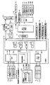
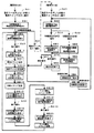
図3は、主基板31における回路構成の一例を示すブロック図である。なお、図2には、パチンコ遊技機1に搭載されている払出制御基板37、インタフェース基板66、中継基板77および演出制御基板80も示されている。主基板31には、プログラムにしたがってパチンコ遊技機1を制御する基本回路(遊技制御手段に相当)53と、ゲートスイッチ32a、始動口スイッチ14a、カウントスイッチ23、および入賞口スイッチ29a,30a,33a,39aからの信号を基本回路53に与える入力ドライバ回路58と、可変入賞球装置15を開閉するソレノイド16、特別可変入賞球装置20を開閉するソレノイド21および大入賞口内の経路を切換えるためのソレノイド21Aを基本回路53からの指令にしたがって駆動する出力回路59とが搭載されている。   FIG. 3 is a block diagram illustrating an example of a circuit configuration in the main board 31. 2 also shows a payout control board 37, an interface board 66, a relay board 77, and an effect control board 80 mounted on the pachinko gaming machine 1. The main board 31 has a basic circuit (corresponding to game control means) 53 for controlling the pachinko gaming machine 1 in accordance with a program, a gate switch 32a, a start port switch 14a, a count switch 23, and winning port switches 29a, 30a, 33a. , 39a to the basic circuit 53, an input driver circuit 58, a solenoid 16 for opening and closing the variable winning ball apparatus 15, a solenoid 21 for opening and closing the special variable winning ball apparatus 20, and a solenoid for switching the path in the big prize opening An output circuit 59 for driving 21A in accordance with a command from the basic circuit 53 is mounted.

なお、ゲートスイッチ32a、始動口スイッチ14a、カウントスイッチ23、入賞口スイッチ29a,30a,33a,39a等のスイッチは、センサと称されているものでもよい。すなわち、遊技球を検出できる遊技媒体検出手段(この例では遊技球検出手段)であれば、その名称を問わない。入賞検出を行なう始動口スイッチ14a、カウントスイッチ23、および入賞口スイッチ29a,30a,33a,39aの各スイッチは、入賞領域への遊技球の入賞を検出する入賞検出手段でもある。なお、ゲート32のような通過ゲートであっても、賞球の払出しが行なわれるものであれば、通過ゲートへ遊技球が進入することが入賞になり、通過ゲートに設けられているスイッチ(たとえばゲートスイッチ32a)が入賞検出手段になる。   Note that the switches such as the gate switch 32a, the start port switch 14a, the count switch 23, and the winning port switches 29a, 30a, 33a, and 39a may be referred to as sensors. That is, the name of the game medium detection means is not limited as long as it is a game medium detection means (game ball detection means in this example) that can detect a game ball. Each of the start port switch 14a, the count switch 23, and the winning port switches 29a, 30a, 33a, and 39a for detecting the winning is also a winning detecting means for detecting the winning of the game ball in the winning area. Even if a pass gate such as the gate 32 is used, a game ball enters the pass gate if the prize ball is paid out, and a switch (for example, a switch provided in the pass gate (for example, The gate switch 32a) becomes a winning detection means.

基本回路53は、ゲーム制御(遊技進行制御)用のプログラム等を記憶するROM54、ワークメモリとして使用される記憶手段(変動データを記憶する変動データ記憶手段)としてのRAM55、およびプログラムにしたがって制御動作を行なうCPU56を有する遊技制御用マイクロコンピュータ560を含む。なお、この実施の形態では、CPU56とは、基本回路53のうち、プログラムにしたがって動作する中央処理装置(ROM54やRAM55等の記憶手段、I/Oポート部57等を除いた部分)を指し、後述するメイン処理や割込処理(タイマ割込処理)を実行する。また、遊技制御用マイクロコンピュータ560とは、基本回路53のうち、CPU56に加えて、ROM54やRAM55等の記憶手段、I/Oポート部57等を含む部分を指し、各基板(払出制御基板37や演出制御基板80)が搭載するマイクロコンピュータと各種データの送受信を行なう。   The basic circuit 53 includes a ROM 54 for storing a game control (game progress control) program and the like, a RAM 55 as storage means (variation data storage means for storing fluctuation data) used as a work memory, and a control operation according to the program. A game control microcomputer 560 having a CPU 56 for performing In this embodiment, the CPU 56 refers to a central processing unit (a part excluding the storage means such as the ROM 54 and the RAM 55, the I / O port unit 57, etc.) of the basic circuit 53 that operates according to the program. Main processing and interrupt processing (timer interrupt processing) described later are executed. The game control microcomputer 560 refers to a part of the basic circuit 53 including the CPU 56, storage means such as the ROM 54 and RAM 55, the I / O port unit 57, and the like. And transmission / reception of various data to / from the microcomputer mounted on the production control board 80).

この実施の形態では、ROM54、ワークメモリとしての記憶手段であるRAM55およびI/Oポート部57は遊技制御用マイクロコンピュータ560に内蔵されている。すなわち、遊技制御用マイクロコンピュータ560は、1チップマイクロコンピュータである。1チップマイクロコンピュータは、少なくともRAM55が内蔵されていればよく、ROM54は外付けであっても内蔵されていてもよい。   In this embodiment, the ROM 54, the RAM 55 serving as storage means as a work memory, and the I / O port unit 57 are built in the game control microcomputer 560. That is, the game control microcomputer 560 is a one-chip microcomputer. The one-chip microcomputer only needs to include at least the RAM 55, and the ROM 54 may be external or internal.

なお、遊技制御用マイクロコンピュータ560においてCPU56がROM54に格納されているプログラムにしたがって制御を実行するので、以下、遊技制御用マイクロコンピュータ560が実行する(または、処理を行なう)ということは、具体的には、CPU56がプログラムにしたがって制御を実行することである。このことは、主基板31以外の他の基板に搭載されているマイクロコンピュータについても同様である。また、遊技制御手段は、遊技制御用マイクロコンピュータ560を含む基本回路53で実現されている。   In the game control microcomputer 560, the CPU 56 executes control in accordance with a program stored in the ROM 54. Therefore, the game control microcomputer 560 is specifically executed (or performs processing) hereinafter. The CPU 56 executes control according to a program. The same applies to microcomputers mounted on substrates other than the main substrate 31. The game control means is realized by a basic circuit 53 including a game control microcomputer 560.

また、RAM55は、揮発性の記憶手段であるが、その一部または全部が電源基板910において作成されるバックアップ電源によってバックアップされていることにより、不揮発性記憶手段として機能するバックアップRAMである。すなわち、パチンコ遊技機1に対する電力供給が停止しても、所定期間(バックアップ電源としてのコンデンサが放電してバックアップ電源が電力供給不能になるまで)は、RAM55の一部または全部の内容は保存される。特に、少なくとも、遊技状態すなわち遊技制御手段の制御状態に応じたデータ(特別図柄プロセスフラグ等)と未払出賞球数を示すデータは、バックアップRAMに保存される。遊技制御手段の制御状態に応じたデータとは、停電等が生じた後に復旧した場合に、そのデータに基づいて、制御状態を停電等の発生前に復旧させるために必要なデータである。また、制御状態に応じたデータと未払出賞球数を示すデータとを遊技の進行状態を示すデータと定義する。なお、この実施の形態では、RAM55の全部が、電源バックアップされているとする。   The RAM 55 is a volatile storage unit, and is a backup RAM that functions as a non-volatile storage unit because part or all of the RAM 55 is backed up by a backup power source created in the power supply substrate 910. That is, even if the power supply to the pachinko gaming machine 1 is stopped, a part or all of the contents of the RAM 55 is stored for a predetermined period (until the backup power supply cannot be supplied because the capacitor as the backup power supply is discharged). The In particular, at least data (special symbol process flag, etc.) corresponding to the game state, that is, the control state of the game control means, and data indicating the number of unpaid winning balls are stored in the backup RAM. The data corresponding to the control state of the game control means is data necessary for restoring the control state before the occurrence of a power failure or the like based on the data when the power is restored after a power failure or the like occurs. Further, data corresponding to the control state and data indicating the number of unpaid winning balls are defined as data indicating the progress state of the game. In this embodiment, it is assumed that the entire RAM 55 is backed up.

なお、パチンコ遊技機1は、バックアップ電源電圧を検知し、検知した電圧値が所定時間継続して一定値以下に低下すると、電力が低下した旨を変動表示装置9に表示したり音やランプを用いて報知する報知手段を設けてもよい。なお、バックアップ電源はコンデンサに限らず、たとえば、電池でもよく、コンデンサと電池とを併用して用いてもよい。要は、バックアップ電源は、瞬停電または停電の間において、たとえば、大当りに関する情報および確変に関する情報等の遊技状態に関する情報を記憶できるように、電力供給が可能なものであればよい。   The pachinko gaming machine 1 detects the backup power supply voltage, and when the detected voltage value continues below for a predetermined time and falls below a certain value, the fact that the power has been reduced is displayed on the variable display device 9 or a sound or lamp is displayed. You may provide the alerting | reporting means to alert | report. The backup power supply is not limited to a capacitor, and may be a battery, for example, or a capacitor and a battery may be used in combination. In short, the backup power supply may be any power supply that can supply power so as to be able to store information related to gaming state such as information related to jackpots and information related to probability change during an instantaneous power failure or power failure.

遊技制御用マイクロコンピュータ560のリセット端子には、電源基板910からのリセット信号が入力される。また、払出制御用マイクロコンピュータのリセット端子にも、電源基板910からのリセット信号が入力される。なお、リセット信号がハイレベルになると遊技制御用マイクロコンピュータ560および払出制御用マイクロコンピュータは動作可能状態になり、リセット信号がローレベルになると遊技制御用マイクロコンピュータ560および払出制御用マイクロコンピュータは動作停止状態になる。したがって、リセット信号がハイレベルである期間は、遊技制御用マイクロコンピュータ560および払出制御用マイクロコンピュータの動作を許容する許容信号が出力されていることになり、リセット信号がローレベルである期間は、遊技制御用マイクロコンピュータ560および払出制御用マイクロコンピュータの動作を停止させる動作停止信号が出力されていることになる。なお、リセット回路をそれぞれの制御基板(主基板31を含む)に搭載してもよいし、複数の制御基板のうちの一つまたは複数にリセット回路を搭載し、そこからリセット信号を他の制御基板に供給するようにしてもよい。   A reset signal from the power supply board 910 is input to the reset terminal of the game control microcomputer 560. The reset signal from the power supply board 910 is also input to the reset terminal of the payout control microcomputer. When the reset signal becomes high level, the game control microcomputer 560 and the payout control microcomputer become operable, and when the reset signal becomes low level, the game control microcomputer 560 and the payout control microcomputer stop operating. It becomes a state. Therefore, during the period in which the reset signal is at a high level, an allowance signal that allows the operation of the game control microcomputer 560 and the payout control microcomputer is output, and during the period in which the reset signal is at a low level, An operation stop signal for stopping the operations of the game control microcomputer 560 and the payout control microcomputer is output. A reset circuit may be mounted on each control board (including the main board 31), or a reset circuit is mounted on one or more of the plurality of control boards, and a reset signal is sent from there to another control circuit. You may make it supply to a board | substrate.

さらに、基本回路53の入力ポートには、払出制御基板37を経由して、電源基板910からの電源電圧が所定値以下に低下したことを示す電源断信号が入力される。また、基本回路53の入力ポートには、遊技制御用マイクロコンピュータ560等のマイクロコンピュータのRAMの内容をクリアすることを指示するための前述したクリアスイッチ912が操作されたことを示すクリア信号が入力される。   Furthermore, a power-off signal indicating that the power supply voltage from the power supply board 910 has decreased to a predetermined value or less is input to the input port of the basic circuit 53 via the payout control board 37. Further, a clear signal indicating that the above-described clear switch 912 for instructing to clear the contents of the RAM of the microcomputer such as the game control microcomputer 560 is input to the input port of the basic circuit 53. Is done.

クリア信号は、主基板31において分岐され、演出制御基板80にも供給される。なお、遊技制御用マイクロコンピュータ560が入力ポートを介して入力したクリア信号の状態を、出力ポートを介して演出制御基板80に出力してもよい。   The clear signal is branched at the main board 31 and is also supplied to the effect control board 80. Note that the state of the clear signal input by the game control microcomputer 560 via the input port may be output to the effect control board 80 via the output port.

遊技制御用マイクロコンピュータ560は、演出制御基板80に表示制御、音制御、および、ランプ制御を含む演出制御を指令するための制御信号としての演出制御コマンド(演出制御信号)を送信する。演出制御基板80には、中継基板77を介して遊技制御用マイクロコンピュータ560からの演出制御コマンドを受信し、変動表示装置9での表示制御を行なう演出制御用マイクロコンピュータ(図9参照)等の電気部品制御手段が搭載されている。主基板31と演出制御基板80との間には、演出制御信号としての演出制御コマンドをパラレル信号で送信するためのパラレル信号線として、8本の信号線と、ストローブ信号としての演出制御INT信号を送信するための1本の信号線とが設けられている。   The game control microcomputer 560 transmits an effect control command (effect control signal) as a control signal for instructing effect control including display control, sound control, and lamp control to the effect control board 80. The effect control board 80 receives an effect control command from the game control microcomputer 560 via the relay board 77 and performs an effect control microcomputer (see FIG. 9) that performs display control on the variable display device 9. Electrical component control means is mounted. Between the main board 31 and the effect control board 80, eight signal lines and an effect control INT signal as a strobe signal are used as parallel signal lines for transmitting an effect control command as an effect control signal as a parallel signal. Is provided with one signal line.

この実施の形態では、演出制御基板80等に搭載されている演出制御手段(演出制御用マイクロコンピュータや各種処理回路で構成される。)が、中継基板77を介して遊技制御用マイクロコンピュータ560からの演出制御コマンドを受信し、飾り図柄を変動表示する変動表示装置9の表示制御を行なう。また、演出制御手段は、音声出力基板70を介してスピーカ27の音出力制御を行なったり、ランプドライバ基板35を介して各ランプ25,28a,28b,28cの表示制御等を行なう。また、この実施の形態では、「演出制御」とは、変動表示装置9の表示制御や、スピーカ27の音出力制御、各ランプ25,28a,28b,28cの表示制御を行なうことによって、遊技演出等の演出を行なうことをいう。また、この実施の形態では、演出制御手段は、変動表示装置9の表示制御、スピーカ27の音出力制御、および各ランプ25,28a,28b,28cの表示制御を行なう演出制御用マイクロコンピュータ100や各種処理回路(たとえば、後述するリアルタイムクロック353やバックアップ電源回路355、音声合成用IC703)によって実現される。   In this embodiment, effect control means (comprising an effect control microcomputer and various processing circuits) mounted on the effect control board 80 and the like is provided from the game control microcomputer 560 via the relay board 77. Display control command is received, and the display control of the variable display device 9 that displays the decorative symbols in a variable manner is performed. Further, the effect control means performs sound output control of the speaker 27 via the audio output board 70, and performs display control of each lamp 25, 28 a, 28 b, 28 c via the lamp driver board 35. In this embodiment, “effect control” means display control of the variable display device 9, sound output control of the speaker 27, display control of the lamps 25, 28a, 28b, and 28c, thereby providing a game effect. It means performing such as. In this embodiment, the effect control means includes an effect control microcomputer 100 that performs display control of the variable display device 9, sound output control of the speaker 27, and display control of the lamps 25, 28a, 28b, and 28c. This is realized by various processing circuits (for example, a real-time clock 353, a backup power supply circuit 355, and a speech synthesis IC 703 described later).

演出制御用マイクロコンピュータは、演出制御コマンドに応じて、変動表示装置9の変動表示等の各種表示の演出に関する制御の他に、賞球ランプ51、球切れランプ52、装飾ランプ25、天枠ランプ28a、左枠ランプ28bおよび右枠ランプ28cの制御(ランプ制御)と、スピーカ27を用いた遊技音発生制御(音制御)とを含む各種演出に関する制御を行なう。演出制御基板80には、演出制御用マイクロコンピュータの他に、たとえば、画像表示を行なう表示制御機能および高速描画機能を有する処理装置であり、変動表示装置9の表示制御を行なうVDP(Video Display Processor )、変動表示装置9に表示する画像データを予め格納するキャラクタROM、および、VDPによって生成された画像データを展開するためのVRAM(Video Random Access Memory)が搭載されている。演出制御基板80の詳細な構成については、図5を用いて後述する。   The effect control microcomputer responds to the effect control command, in addition to control related to various display effects such as variable display of the variable display device 9, a prize ball lamp 51, a ball break lamp 52, a decoration lamp 25, and a ceiling lamp. Control relating to various effects including control of 28a, left frame lamp 28b and right frame lamp 28c (lamp control) and game sound generation control (sound control) using the speaker 27 is performed. The effect control board 80 is, for example, a processing device having a display control function for performing image display and a high-speed drawing function in addition to the effect control microcomputer, and a VDP (Video Display Processor) for performing display control of the variable display device 9. ), A character ROM for storing image data to be displayed on the variable display device 9 in advance, and a VRAM (Video Random Access Memory) for expanding the image data generated by the VDP. The detailed configuration of the effect control board 80 will be described later with reference to FIG.

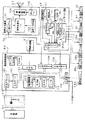
図5は、演出制御基板80、ランプドライバ基板35および音声出力基板70の回路構成例を示すブロック図である。図5に示すように、この実施の形態では、パチンコ遊技機1は、変動表示装置9の表示制御を行なうための演出制御基板80と、スピーカ27の音出力制御を行なうための音声出力基板70と、各ランプ25,28a,28b,28cの表示制御を行なうためのランプドライバ基板35とを含む。なお、この実施の形態では、複数の制御基板(演出制御基板80,音声出力基板70、ランプドライバ基板35)を用いて、変動表示装置9の表示制御や、スピーカ27の音出力制御、各ランプ25,28a,28b,28cの表示制御を行なう場合を説明するが、1つの制御基板(たとえば、1つの演出制御基板)を用いて行なってもよい。   FIG. 5 is a block diagram illustrating a circuit configuration example of the effect control board 80, the lamp driver board 35, and the audio output board 70. As shown in FIG. 5, in this embodiment, the pachinko gaming machine 1 has an effect control board 80 for performing display control of the variable display device 9 and an audio output board 70 for performing sound output control of the speaker 27. And a lamp driver board 35 for performing display control of each lamp 25, 28a, 28b, 28c. In this embodiment, a plurality of control boards (production control board 80, audio output board 70, lamp driver board 35) are used to control display of the variable display device 9, sound output control of the speaker 27, and each lamp. Although the case where display control of 25, 28a, 28b, 28c is performed will be described, it may be performed using one control board (for example, one production control board).

演出制御基板80は、表示制御用のプログラム等を記憶するROM84と、ワークメモリとして使用されるRAM85と、プログラムにしたがって表示制御動作を行なうプロセッサであるCPU101と、I/Oポート87とを含む。なお、RAM85は外付けであってもよい。演出制御基板80には、演出制御用マイクロコンピュータ100の他に、たとえば、画像表示を行なう表示制御機能および高速描画機能を有する処理装置であり、変動表示装置9の表示制御を行なうVDP(Video Display Processor )88、変動表示装置9に表示する画像データを予め格納するキャラクタROM89、および、VDP88によって生成された画像データを展開するためのVRAM(Video Random Access Memory)83が搭載されている。VDP109は、演出制御用マイクロコンピュータ100とは独立したアドレス空間を有し、そこにVRAM83をマッピングする。VRAM83は、VDP109によって生成された画像データを展開するためのバッファメモリである。そして、VDP109は、VRAM83内の画像データを変動表示装置9に出力する。   The effect control board 80 includes a ROM 84 that stores a display control program and the like, a RAM 85 that is used as a work memory, a CPU 101 that is a processor that performs a display control operation in accordance with the program, and an I / O port 87. The RAM 85 may be externally attached. The effect control board 80 is, for example, a processing device having a display control function for performing image display and a high-speed drawing function in addition to the effect control microcomputer 100, and a VDP (Video Display) for performing display control of the variable display device 9. Processor) 88, a character ROM 89 for storing image data to be displayed on the variable display device 9 in advance, and a VRAM (Video Random Access Memory) 83 for expanding the image data generated by the VDP 88. The VDP 109 has an address space independent of the production control microcomputer 100 and maps the VRAM 83 therein. The VRAM 83 is a buffer memory for expanding image data generated by the VDP 109. Then, the VDP 109 outputs the image data in the VRAM 83 to the variable display device 9.

遊技制御用マイクロコンピュータ560は、演出制御基板80に表示制御、音制御、および、ランプ制御を含む演出制御を指令するための制御信号としての演出制御コマンドと演出制御INT信号)とを送信する。演出制御基板80において、演出制御用マイクロコンピュータ100は、内蔵または外付けのROM84に格納されたプログラムにしたがって動作し、中継基板77を介して入力される主基板31からの演出制御INT信号に応じて、入力ドライバ102および入力ポート103を介して演出制御コマンドを受信する。また、演出制御用マイクロコンピュータ100は、演出制御コマンドに基づいて、VDP(ビデオディスプレイプロセッサ)109に、LCDを用いた変動表示装置9の表示制御を行なわせる。   The game control microcomputer 560 transmits an effect control command and an effect control INT signal as control signals for instructing effect control including display control, sound control, and lamp control to the effect control board 80. In the effect control board 80, the effect control microcomputer 100 operates in accordance with a program stored in a built-in or external ROM 84 and responds to an effect control INT signal from the main board 31 input via the relay board 77. The presentation control command is received via the input driver 102 and the input port 103. Further, the effect control microcomputer 100 causes the VDP (video display processor) 109 to perform display control of the variable display device 9 using the LCD based on the effect control command.

具体的に、演出制御用マイクロコンピュータ100は、受信した演出制御コマンドにしたがってキャラクタROM89から必要なデータを読出す。キャラクタROM89は、変動表示装置9に表示される画像の中でも使用頻度の高いキャラクタ画像データ、具体的には、人物、文字、図形または記号等(飾り図柄を含む)を予め格納しておくための記憶手段である。演出制御用マイクロコンピュータ100は、キャラクタROM89から読出したデータをVDP109に出力する。VDP109は、演出制御用マイクロコンピュータ100から入力されたデータに基づいて変動表示装置9の表示制御を実行する。   Specifically, the production control microcomputer 100 reads necessary data from the character ROM 89 in accordance with the received production control command. The character ROM 89 stores character image data frequently used among images displayed on the variable display device 9, specifically, a person, a character, a figure, a symbol, or the like (including decorative designs) in advance. It is a storage means. The effect control microcomputer 100 outputs the data read from the character ROM 89 to the VDP 109. The VDP 109 performs display control of the variable display device 9 based on the data input from the effect control microcomputer 100.

演出制御コマンドおよび演出制御INT信号は、演出制御基板80において、まず、入力ドライバ102に入力する。入力ドライバ102は、中継基板77から入力された信号を演出制御基板80の内部に向かう方向にしか通過させない(演出制御基板80の内部から中継基板77への方向には信号を通過させない)信号方向規制手段としての単方向性回路でもある。   The effect control command and the effect control INT signal are first input to the input driver 102 on the effect control board 80. The input driver 102 passes the signal input from the relay board 77 only in the direction toward the inside of the effect control board 80 (does not pass the signal in the direction from the inside of the effect control board 80 to the relay board 77). It is also a unidirectional circuit as a regulating means.

中継基板77には、主基板31から入力された信号を演出制御基板80に向かう方向にしか通過させない(演出制御基板80から中継基板77への方向には信号を通過させない)信号方向規制手段としての単方向性回路が搭載されている。単方向性回路として、たとえばダイオードやトランジスタが使用される。図5には、単方向性回路として、ダイオードが例示されている。また、単方向性回路は、各信号毎に設けられる。   As a signal direction regulating means, the signal inputted from the main board 31 is allowed to pass through the relay board 77 only in the direction toward the effect control board 80 (the signal is not passed in the direction from the effect control board 80 to the relay board 77). The unidirectional circuit is installed. For example, a diode or a transistor is used as the unidirectional circuit. FIG. 5 illustrates a diode as a unidirectional circuit. A unidirectional circuit is provided for each signal.

なお、演出制御コマンドを送信するための信号線としては、前述の8本というようなパラレル信号線を用いる構成に代えて、1本の信号線、すなわち、シリアル信号線を用いる構成を採用してもよい。シリアル信号線を用いる場合には、演出制御コマンドをシリアルデータとし、そのシリアルデータの送信前にローレベル信号のスタートビットを送信し、そのシリアルデータの送信後にハイレベル信号のストップビットを送信する。このようなスタートビットとストップビットとにより演出制御コマンドの取込みタイミングが示されるので、演出制御用マイクロコンピュータ100では、スタートビットとストップビットとの間に送信されたシリアルデータを演出制御コマンドとして受信する。   In addition, as a signal line for transmitting the effect control command, a configuration using one signal line, that is, a serial signal line is adopted instead of the configuration using the parallel signal lines such as the above-mentioned eight. Also good. When the serial signal line is used, the production control command is serial data, the start bit of the low level signal is transmitted before the transmission of the serial data, and the stop bit of the high level signal is transmitted after the transmission of the serial data. Since the start control command capture timing is indicated by such a start bit and stop bit, the effect control microcomputer 100 receives serial data transmitted between the start bit and the stop bit as the effect control command. .

演出制御用マイクロコンピュータ100は、出力ポート104を介して音声出力基板70にスピーカ27を駆動して音声を出力させるための音番号データを出力する。これにより、変動表示装置9での演出表示に対応して(同期して)音声を出力させる音声制御が行なわれる。   The production control microcomputer 100 outputs sound number data for driving the speaker 27 to the sound output board 70 via the output port 104 to output sound. As a result, sound control is performed to output (synchronously) sound in response to the effect display on the variable display device 9.

音声出力基板70は、入出力ドライバ702、音声合成用IC703、音声データROM704、増幅回路705、および、ボリューム706等の音声を出力させる回路が形成された基板である。演出制御用マイクロコンピュータ100は、スピーカ27を駆動するための信号として、音声出力基板70に搭載された音声合成用IC173に対して音番号データを出力する。音声出力基板70において、音番号データは、入出力ドライバ702を介して音声合成用IC173に入力する。音声合成用IC703は、音番号データに応じた音声や効果音を発生し増幅回路705に出力する。増幅回路705は、音声合成用IC703の出力レベルを、ボリューム706で設定されている音量に応じたレベルに増幅した音声信号をスピーカ27に出力する。音声データROM704には、音番号データに応じた制御データが格納されている。音番号データに応じた制御データは、所定期間(たとえば飾り図柄の変動期間)における効果音または音声の出力態様を時系列的に示すデータの集まりである。   The audio output board 70 is a board on which an input / output driver 702, a voice synthesizing IC 703, an audio data ROM 704, an amplifier circuit 705, and a circuit for outputting audio such as a volume 706 are formed. The production control microcomputer 100 outputs sound number data to the speech synthesis IC 173 mounted on the speech output board 70 as a signal for driving the speaker 27. In the voice output board 70, the sound number data is input to the voice synthesis IC 173 via the input / output driver 702. The voice synthesizing IC 703 generates voice or sound effect according to the sound number data, and outputs it to the amplifier circuit 705. The amplification circuit 705 outputs an audio signal obtained by amplifying the output level of the speech synthesis IC 703 to a level corresponding to the volume set by the volume 706 to the speaker 27. The voice data ROM 704 stores control data corresponding to the sound number data. The control data corresponding to the sound number data is a collection of data indicating the sound effect or sound output mode in a time series in a predetermined period (for example, a decorative symbol variation period).

また、演出制御用マイクロコンピュータ100は、入出力ポート105を介してランプドライバ基板35にランプ(各種発光手段)を駆動する信号を出力する。これにより、変動表示装置9での演出表示に対応して(同期して)音声を出力させる音声制御が行なわれる。このように、演出制御用マイクロコンピュータ100により、変動表示装置9での演出表示に対応して(同期して)、音声制御および発光制御が行なわれる。   The effect control microcomputer 100 outputs a signal for driving the lamp (various light emitting means) to the lamp driver board 35 via the input / output port 105. As a result, sound control is performed to output (synchronously) sound in response to the effect display on the variable display device 9. As described above, the sound control and the light emission control are performed by the microcomputer 100 for effect control in correspondence with (in synchronization with) the effect display on the variable display device 9.

ランプドライバ基板35は、入出力ドライバ351およびランプドライバ352等の回路が形成された基板である。ランプドライバ基板35においては、演出制御用マイクロコンピュータ100から出力された各種ランプを駆動する信号を、入出力ドライバ351を介してランプドライバ352が受ける。ランプドライバ352は、その信号を増幅して、賞球ランプ51、球切れランプ52、装飾ランプ25、天枠ランプ28a、左枠ランプ28b、および、右枠ランプ28c等の各種発光手段に供給することにより、当該各種発光手段を駆動する。   The lamp driver substrate 35 is a substrate on which circuits such as an input / output driver 351 and a lamp driver 352 are formed. In the lamp driver board 35, the lamp driver 352 receives signals for driving various lamps output from the effect control microcomputer 100 via the input / output driver 351. The lamp driver 352 amplifies the signal and supplies it to various light emitting means such as a prize ball lamp 51, a ball-out lamp 52, a decoration lamp 25, a top frame lamp 28a, a left frame lamp 28b, and a right frame lamp 28c. As a result, the various light emitting means are driven.

なお、ランプを駆動する信号および音番号データは、演出制御用マイクロコンピュータ100とランプドライバ352および音声合成IC703との間で、双方向通信(信号受信側から送信側に応答信号を送信するような通信)によって伝達される。   The signal for driving the lamp and the sound number data are communicated between the production control microcomputer 100, the lamp driver 352, and the speech synthesis IC 703, such that a response signal is transmitted from the signal receiving side to the transmitting side. Communication).

また、操作ボタン120からの操作信号(操作状態を示す検出信号)が、入力ポート108を介して演出制御用マイクロコンピュータ100に入力される。同様に、前述した電源基板910からのクリア信号が、入力ポート108を介して演出制御用マイクロコンピュータ100に入力される。演出制御用マイクロコンピュータ100は、後述するように、操作ボタン120からの操作信号に基づいて遊技演出を行なう。また、演出制御用マイクロコンピュータ100は、操作ボタン120からの操作信号に基づいて各種設定処理を行なう。この実施の形態では、演出制御用マイクロコンピュータ100は、後述するように、操作ボタン120からの操作信号に基づいて告知演出で遊技者に告知する告知内容を設定する。なお、操作ボタン120からの操作信号に基づいて告知内容を設定するのではなく、ランプドライバ基板35に設けられた演出スイッチ354からのオン/オフ信号に基づいて告知内容を設定してもよい。   In addition, an operation signal (detection signal indicating an operation state) from the operation button 120 is input to the effect control microcomputer 100 via the input port 108. Similarly, the clear signal from the power supply board 910 described above is input to the effect control microcomputer 100 via the input port 108. The effect control microcomputer 100 performs a game effect based on an operation signal from the operation button 120, as will be described later. Further, the production control microcomputer 100 performs various setting processes based on operation signals from the operation buttons 120. In this embodiment, the production control microcomputer 100 sets notification contents to be notified to the player in the notification production based on the operation signal from the operation button 120, as will be described later. Instead of setting the notification content based on the operation signal from the operation button 120, the notification content may be set based on an on / off signal from the effect switch 354 provided on the lamp driver board 35.

また、この実施の形態では、ランプドライバ基板35には、リアルタイムクロック(RTC)モジュール(以下、リアルタイムクロックという)353、演出スイッチ354、バックアップ電源回路355、バックアップRAM356、ROM359、電源監視回路357、および、データ転送コントローラ358が搭載されている。ランプドライバ基板35に設けられたリアルタイムクロック353、演出スイッチ354、バックアップRAM356、ROM359、および電源監視回路357のそれぞれと、演出制御基板80に設けられた演出制御用マイクロコンピュータ100とは、ランプドライバ基板35に設けられた入出力ドライバ351および演出制御基板80に設けられた入出力ポート105を介して接続される。   In this embodiment, the lamp driver board 35 includes a real-time clock (RTC) module (hereinafter referred to as a real-time clock) 353, an effect switch 354, a backup power supply circuit 355, a backup RAM 356, a ROM 359, a power supply monitoring circuit 357, and A data transfer controller 358 is mounted. Each of the real-time clock 353, the effect switch 354, the backup RAM 356, the ROM 359, and the power supply monitoring circuit 357 provided on the lamp driver board 35 and the effect control microcomputer 100 provided on the effect control board 80 includes a lamp driver board. 35 and an input / output driver 351 provided in 35 and an input / output port 105 provided in the effect control board 80.

リアルタイムクロック353は、現在の「年」,「月」,「日」,「曜日」,「時」,「分」,「秒」を示すために計時を行ない、その計時値(「年」,「月」,「日」,「曜日」,「時」,「分」,「秒」のすべてのカウント値のうちの一部または全部)を出力する装置である。   The real-time clock 353 measures time to indicate the current “year”, “month”, “day”, “day of the week”, “hour”, “minute”, “second”, and the time value (“year”, This is a device that outputs “a part or all of the count values of“ month ”,“ day ”,“ day of the week ”,“ hour ”,“ minute ”, and“ second ”).

リアルタイムクロック353の計時値は、バックアップRAM356に記憶される。バックアップRAM356は、たとえば、揮発性の記憶手段であるSRAM(Static Random Access Memory)を用いて構成された記憶手段であり、パチンコ遊技機1の稼動開始日時およびリアルタイムクロック353の計時値等各種の情報が記憶される。バックアップRAM356は、パチンコ遊技機1への電源電力の供給が断たれているときでも、バックアップ電源回路355から供給されるバックアップ電力に基づいて、記憶データが保持される。バックアップRAM356は、演出制御用マイクロコンピュータ100と接続されており、演出制御用マイクロコンピュータ100により記憶情報の管理が行なわれる。また、バックアップRAM356は、データ転送コントローラ358を介してリアルタイムクロック353と接続されている。   The time measured value of the real time clock 353 is stored in the backup RAM 356. The backup RAM 356 is storage means configured using, for example, SRAM (Static Random Access Memory) which is volatile storage means, and various information such as the operation start date and time of the pachinko gaming machine 1 and the time value of the real-time clock 353. Is memorized. The backup RAM 356 holds stored data based on the backup power supplied from the backup power supply circuit 355 even when the supply of power to the pachinko gaming machine 1 is cut off. The backup RAM 356 is connected to the effect control microcomputer 100, and the stored information is managed by the effect control microcomputer 100. The backup RAM 356 is connected to the real time clock 353 via the data transfer controller 358.

バックアップRAM356の記憶領域としては、パチンコ遊技機1の稼動開始日時を記憶する稼動開始日時記憶領域、および、リアルタイムクロック353による日時(「年」,「月」,「日」,「曜日」,「時」,「分」,「秒」)の計時値(現在の計時値)を特定可能な計時情報としての計時値データを記憶する計時値データ記憶領域等の各種の記憶領域が設けられている。   The storage area of the backup RAM 356 includes an operation start date / time storage area for storing the operation start date / time of the pachinko gaming machine 1 and a date / time (“year”, “month”, “day”, “day of the week”, “ Various storage areas such as a time value data storage area for storing time value data as time information that can specify the time value (current time value) (hour, minute, second)) are provided. .

データ転送コントローラ358は、所定周期(1秒よりも短い周期)でリアルタイムクロック353の計時値(「年」〜「秒」のすべての計時値)のデータを読出し、そのデータをバックアップRAM356に転送し、バックアップRAM356の計時値記憶領域のアドレスを指定して、計時値データ記憶領域にそのデータを上書きする態様で書込む。これにより、バックアップRAM356の計時値データ記憶領域に記憶された計時値のデータは、リアルタイムクロック353の計時値のデータと同じデータとなる。データ転送コントローラ358は、たとえば、DMAコントローラ(Direct Memory Access)のようにCPUを介さずに、リアルタイムクロック353から直接的にデータをメモリに転送して書込む回路により構成される。なお、データ転送コントローラ358は、リアルタイムクロック353からバックアップRAM356へ計時値のデータを転送できる回路であればどのような回路で構成されてもよい。   The data transfer controller 358 reads the data of the time values (all time values from “year” to “second”) of the real-time clock 353 at a predetermined cycle (cycle shorter than 1 second), and transfers the data to the backup RAM 356. Then, the address of the timekeeping value storage area of the backup RAM 356 is designated, and the data is written in a manner to overwrite the data in the timekeeping value data storage area. As a result, the time value data stored in the time value data storage area of the backup RAM 356 is the same data as the time value data of the real-time clock 353. The data transfer controller 358 is configured by a circuit that transfers data directly from a real-time clock 353 to a memory without using a CPU, such as a DMA controller (Direct Memory Access), for example. The data transfer controller 358 may be configured by any circuit as long as it can transfer the time-measured data from the real-time clock 353 to the backup RAM 356.

また、バックアップRAM356の計時値データ記憶領域以外の記憶領域に記憶される各種のデータは、演出制御用マイクロコンピュータ100が、随時、書込み先のアドレスを指定して、そのアドレスにデータを書込むことにより各種記憶領域に書込まれる。   The various data stored in the storage area other than the timekeeping value data storage area of the backup RAM 356 is written by the production control microcomputer 100 at any time by designating the address of the writing destination. Are written in various storage areas.

演出制御用マイクロコンピュータ100は、バックアップRAM356の計時値データ記憶領域に記憶されている計時データを必要に応じて読出すことにより、リアルタイムクロック353で計時されている現在の日付(年、月、日、曜日)を示す日付情報や現在の時刻(時、分、秒)を示す時刻情報を取得し、現在の日時に基づいて各種処理を実行する。リアルタイムクロック353、バックアップRAM356、および、データ転送コントローラ358のそれぞれは、遊技場の営業時間(たとえば、10時00分〜23時00分)中のように、電源スイッチ911がオン状態となっていることによりパチンコ遊技機1の電源電力が供給されているときにはパチンコ遊技機1からの電源電力によって動作し、遊技場の閉店時間中のようにパチンコ遊技機1の電源スイッチ911がオフ状態となっていることによりパチンコ遊技機1の電源電力が供給されていないときには、ランプドライバ基板35に搭載されたバックアップ電源回路355から供給される電源によって動作する。   The production control microcomputer 100 reads the time data stored in the time value data storage area of the backup RAM 356 as necessary, and thereby reads the current date (year, month, day) measured by the real-time clock 353. Date information indicating the day of the week) and time information indicating the current time (hour, minute, second) are acquired, and various processes are executed based on the current date and time. In each of the real-time clock 353, the backup RAM 356, and the data transfer controller 358, the power switch 911 is in an ON state, such as during game hours (for example, 10:00 to 23:00). Thus, when the power supply of the pachinko gaming machine 1 is supplied, the power supply power from the pachinko gaming machine 1 is operated, and the power switch 911 of the pachinko gaming machine 1 is turned off during the closing time of the game hall. Therefore, when the power of the pachinko gaming machine 1 is not supplied, the power is supplied from the backup power supply circuit 355 mounted on the lamp driver board 35.

バックアップ電源回路355は、たとえば、パチンコ遊技機1への電源電力が供給されているときにその電力に基づいて電荷を蓄積することによりバックアップ用の電力を蓄積(充電)し、パチンコ遊技機1への電源電力が供給されていないときでも、蓄積した電荷を放電することにより、蓄積した電力をバックアップ用の電力として供給するコンデンサ式の充放電回路により構成されている。したがって、パチンコ遊技機1の電源が切られている場合であっても、リアルタイムクロック353は現在の日時を計時することができ、データ転送コントローラ358はデータの転送をすることができ、バックアップRAM356は、リアルタイムクロック353により計時されている現在の日時を更新しながら記憶することができる。バックアップ電源回路355は、たとえば、4ヶ月間程度の期間に亘りバックアップ用の電力を供給可能なものである。なお、バックアップ電源回路355は、少なくとも、遊技場について一般的に想定される連続な営業休み期間中においてバックアップ用の電力を供給可能なものであればよい。また、バックアップ電源回路355は、着脱可能な態様で設けられてもよく、着脱不可能な態様で設けられてもよい。また、バックアップ電源回路355は、パチンコ遊技機1への電源電力が供給されていないときにのみ、リアルタイムクロック353、データ転送コントローラ358、および、バックアップRAM356に電力を供給するためにこれらに電気的に接続され、パチンコ遊技機1への電源電力が供給されているときには、リアルタイムクロック353、データ転送コントローラ358、および、バックアップRAM356に電力を供給しない(そのときにはパチンコ遊技機1への電源電力がこれらに供給される)ようにこれらから電気的に切断されるように構成されてもよい。   The backup power supply circuit 355 accumulates (charges) backup power by accumulating charges based on the power when the power supply power to the pachinko gaming machine 1 is supplied, for example, to the pachinko gaming machine 1 Even when the power source power is not supplied, the capacitor type charge / discharge circuit is configured to supply the stored power as backup power by discharging the stored charge. Therefore, even when the pachinko gaming machine 1 is powered off, the real-time clock 353 can measure the current date and time, the data transfer controller 358 can transfer data, and the backup RAM 356 The current date and time measured by the real time clock 353 can be stored while being updated. The backup power supply circuit 355 can supply power for backup over a period of about four months, for example. Note that the backup power supply circuit 355 may be any circuit as long as it can supply power for backup during a continuous business holiday period generally assumed for amusement halls. Further, the backup power supply circuit 355 may be provided in a detachable manner or may be provided in a non-detachable manner. Further, the backup power supply circuit 355 is electrically connected to the real-time clock 353, the data transfer controller 358, and the backup RAM 356 only when the power supply to the pachinko gaming machine 1 is not supplied. When power is supplied to the pachinko gaming machine 1 and connected to the pachinko gaming machine 1, power is not supplied to the real-time clock 353, the data transfer controller 358, and the backup RAM 356. May be configured to be electrically disconnected from them.

また、演出スイッチ354の操作信号は、演出制御用マイクロコンピュータ100に入力される。電源監視回路357は、バックアップ電源回路356の電圧を計測して監視する回路であり、当該電圧が所定値以下に低下したときに、電圧低下信号を演出制御用マイクロコンピュータ100に出力する。なお、電圧低下信号は、バックアップ電源回路356の出力電圧が0Vになったときに出力されるように設定してもよく、また、バックアップ電源回路356の出力電圧が0V以上でバックアップRAM356の記憶データをバックアップ記憶できない電圧として予め定められた電圧に設定してもよい。電圧低下信号は、演出制御用マイクロコンピュータ100は、電圧低下信号が入力されたときに、バックアップRAM356の記憶データをバックアップ記憶できるバックアップ電力の供給がなくなったと判断し、後述するような制御を行なう。   Further, the operation signal of the effect switch 354 is input to the effect control microcomputer 100. The power supply monitoring circuit 357 is a circuit that measures and monitors the voltage of the backup power supply circuit 356, and outputs a voltage drop signal to the effect control microcomputer 100 when the voltage drops below a predetermined value. The voltage drop signal may be set so as to be output when the output voltage of the backup power supply circuit 356 becomes 0V, or the data stored in the backup RAM 356 when the output voltage of the backup power supply circuit 356 is 0V or higher. May be set to a predetermined voltage as a voltage that cannot be backed up. When the voltage drop signal is input, the production control microcomputer 100 determines that there is no supply of backup power that can store the data stored in the backup RAM 356, and performs control as described later.

なお、バックアップ電源回路355を電池により構成し、リアルタイムクロック353、バックアップRAM356、および、データ転送コントローラ358のそれぞれは、パチンコ遊技機1に電源が供給されていないときに、電池により構成されたバックアップ電源回路から供給される電源によって動作するようにしてもよい。また、バックアップ電源回路355を電池により構成し、リアルタイムクロック353、バックアップRAM356、および、データ転送コントローラ358のそれぞれは、パチンコ遊技機1に電源が供給されているときであっても電池により構成されたバックアップ電源回路から供給される電源によって動作するようにしてもよい。これらの場合に用いる電池は、充電が不可能な一次電池と、充電が可能な二次電池とのどちらを用いてもよい。バックアップ電源回路355として二次電池を用いるときには、パチンコ遊技機1において二次電池がセットされた状態で電源電力に基づいて充電可能な二次電池と、パチンコ遊技機1から取外して所定の充電器により充電可能な二次電池とのどちらを用いてもよい。つまり、バックアップ電源回路355としては、パチンコ遊技機1への電源電力が供給されていないときでも所定時間は電力を供給する手段であれば、各種コンデンサおよび電池のうち、どのようなものを用いてもよい。   The backup power supply circuit 355 is configured by a battery, and each of the real-time clock 353, the backup RAM 356, and the data transfer controller 358 is a backup power supply configured by a battery when power is not supplied to the pachinko gaming machine 1. You may make it operate | move with the power supply supplied from a circuit. Further, the backup power supply circuit 355 is configured by a battery, and each of the real-time clock 353, the backup RAM 356, and the data transfer controller 358 is configured by a battery even when power is supplied to the pachinko gaming machine 1. You may make it operate | move with the power supply supplied from a backup power supply circuit. The battery used in these cases may be either a primary battery that cannot be charged or a secondary battery that can be charged. When a secondary battery is used as the backup power supply circuit 355, a secondary battery that can be charged based on power supply power in a state where the secondary battery is set in the pachinko gaming machine 1, and a predetermined charger that is removed from the pachinko gaming machine 1 Any of the rechargeable secondary batteries can be used. That is, as the backup power supply circuit 355, any of various capacitors and batteries can be used as long as it is a means for supplying power for a predetermined time even when power to the pachinko gaming machine 1 is not supplied. Also good.

また、リアルタイムクロック353、バックアップRAM356、および、データ転送コントローラ358のそれぞれをランプドライバ基板35ではなく、演出制御基板80や音声出力基板70に搭載してもよい。また、リアルタイムクロック353、バックアップRAM356、および、データ転送コントローラ358のそれぞれを主基板31に搭載するようにしてもよい。   In addition, each of the real-time clock 353, the backup RAM 356, and the data transfer controller 358 may be mounted on the effect control board 80 and the audio output board 70 instead of the lamp driver board 35. In addition, each of the real-time clock 353, the backup RAM 356, and the data transfer controller 358 may be mounted on the main board 31.

また、この実施の形態では、演出制御用マイクロコンピュータ100は、操作ボタン120からの操作信号に基づいて遊技演出を行なう。また、演出制御用マイクロコンピュータ100は、操作ボタン120からの操作信号に基づいて各種設定処理を行なう。この実施の形態では、演出制御用マイクロコンピュータ100は、後述するように、操作ボタン120からの操作信号に基づいて告知演出で遊技者に告知する告知内容を設定する。なお、操作ボタン120からの操作信号に基づいて告知内容を設定するのではなく、ランプドライバ基板35に設けられた演出スイッチ354からのオン/オフ信号に基づいて告知内容を設定してもよい。また、演出スイッチ354を演出制御基板80または音声出力基板70に設けてもよい。また、演出スイッチ354は、前述したモーメンタリスイッチに限らず、ディップスイッチやプッシュロックスイッチ、ロータリスイッチのようにスイッチ側でオン/オフを固定できるものであってもよい。   In this embodiment, the effect control microcomputer 100 performs a game effect based on an operation signal from the operation button 120. Further, the production control microcomputer 100 performs various setting processes based on operation signals from the operation buttons 120. In this embodiment, the production control microcomputer 100 sets notification contents to be notified to the player in the notification production based on the operation signal from the operation button 120, as will be described later. Instead of setting the notification content based on the operation signal from the operation button 120, the notification content may be set based on an on / off signal from the effect switch 354 provided on the lamp driver board 35. Further, the effect switch 354 may be provided on the effect control board 80 or the sound output board 70. Further, the effect switch 354 is not limited to the momentary switch described above, but may be one that can be turned on / off on the switch side, such as a dip switch, a push lock switch, or a rotary switch.

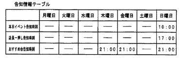
ROM359は、リアルタイムクロック353の計時値に基づいて所定のタイミングで実行する各種演出の実行条件等、予め定められた各種の情報が記憶されている。ここで、演出の実行条件とは、演出を実行するための条件として用いる情報をいい、たとえば、演出の実行の有無に関する情報、演出の種類に関する情報、および、演出を実行する日時(日、時刻)に関する情報を含む。なお、演出の実行条件は、所定の演出の実行の有無に関する情報のみであってもよく、これら3つの情報のいずれか1つまたは2つの組合せであってもよい。   The ROM 359 stores various information such as execution conditions for various effects executed at a predetermined timing based on the time value of the real-time clock 353. Here, the performance execution condition refers to information used as a condition for performing the performance. For example, information regarding presence / absence of performance, information regarding the type of performance, and date and time (day, time) ) Information. It should be noted that the performance execution condition may be only information related to the presence or absence of execution of the predetermined performance, or any one or a combination of these three pieces of information.

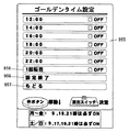
図7は、ランプドライバ基板35に設けられたROM359およびバックアップRAM356のそれぞれの記憶領域の構成を示す模式図である。図7においては、ROM359における主要な記憶領域と、バックアップRAM356における主要な記憶領域とが示されている。図7(a)に示すように、ROM359においては、ゴールデンタイム設定データ領域、および、オールマイティー図柄設定データ領域等の各種データを格納(記憶)した記憶領域が設けられている。ゴールデンタイム設定データ領域は、後述する特別のデモンストレーション表示の演出およびミッション演出に関し、演出を必ず実行する時刻等の演出の実行条件としての固定実行条件情報(実行条件が変更不可能であり、固定的に演出を実行する実行条件を特定する情報)を記憶する領域である。具体的に、その固定実行条件情報には、特別のデモンストレーション表示の演出に関し、演出の実行の有無に関する情報、演出の種類(特別のデモンストレーション表示の演出を示す情報)を示す情報、および、特別のデモンストレーション表示の演出を実行する時刻に関する情報を含む。また、オールマイティー図柄設定データ領域は、後述するオールマイティー図柄を用いた特別の飾り図柄の変動表示の固定実行条件情報を記憶する領域である。具体的に、その固定実行条件情報には、オールマイティー図柄を用いた特別の飾り図柄の変動表示に関し、演出の実行の有無に関する情報、演出の種類(オールマイティー図柄を用いた特別の飾り図柄の変動表示の演出)を示す情報、および、演出を実行する日時に関する情報を含む。   FIG. 7 is a schematic diagram showing the configuration of the storage areas of the ROM 359 and the backup RAM 356 provided on the lamp driver board 35. In FIG. 7, main storage areas in the ROM 359 and main storage areas in the backup RAM 356 are shown. As shown in FIG. 7A, the ROM 359 is provided with a storage area for storing (storing) various data such as a golden time setting data area and an almighty symbol setting data area. The golden time setting data area is a fixed execution condition information (execution condition cannot be changed and fixed as an execution condition of an effect such as a time at which the effect is always executed) regarding a special demonstration display effect and a mission effect described later. This is an area for storing information for specifying an execution condition for executing the production. Specifically, the fixed execution condition information includes information regarding presence / absence of execution, information indicating the type of effect (information indicating the effect of the special demonstration display), and information regarding the effect of the special demonstration display. Contains information about the time at which the demonstration display effect is executed. The almighty symbol setting data area is an area for storing fixed execution condition information for a variable display of a special decorative symbol using an almighty symbol, which will be described later. Specifically, the fixed execution condition information includes information on whether or not a special decoration design using an almighty symbol is displayed, information on whether or not the performance is executed, and the type of production (variable display of a special decorative design using an almighty symbol Information indicating the production date) and information regarding the date and time when the production is executed.

図7(b)に示すように、バックアップRAM356においては、前述した計時値データ記憶領域、および、稼動開始日時格納領域の他に、ゴールデンタイム設定領域、および、オールマイティー図柄設定領域等の各種データを格納(記憶)した記憶領域が設けられている。ゴールデンタイム設定領域は、後述する特別のデモンストレーション表示の演出およびミッション演出に関し、入力により設定された演出を実行する設定時刻等の入力により設定された演出の実行条件としての設定実行条件情報を記憶する領域である。具体的に、その設定実行条件情報には、特別のデモンストレーション表示の演出に関し、演出の実行の有無に関する情報、演出の種類(特別のデモンストレーション表示の演出を示す情報)を示す情報、および、特別のデモンストレーション表示の演出を実行する時刻に関する情報を含む。また、オールマイティー図柄設定領域は、後述するオールマイティー図柄を用いた特別の飾り図柄の変動表示の設定実行条件情報を記憶する領域である。具体的に、その設定実行条件情報には、オールマイティー図柄を用いた特別の飾り図柄の変動表示に関し、演出の実行の有無に関する情報、演出の種類(オールマイティー図柄を用いた特別の飾り図柄の変動表示の演出)を示す情報、および、演出を実行する日時に関する情報を含む。   As shown in FIG. 7B, the backup RAM 356 stores various data such as the golden time setting area and the almighty symbol setting area in addition to the above-described time value data storage area and operation start date / time storage area. A storage area (stored) is provided. The golden time setting area stores setting execution condition information as an execution condition set for an effect set by an input such as a set time for executing the effect set by the input with respect to the effect of a special demonstration display and a mission effect to be described later. It is an area. Specifically, the setting execution condition information includes information regarding presence / absence of execution, information indicating the type of effect (information indicating the effect of the special demonstration display), and information regarding the effect of the special demonstration display. Contains information about the time at which the demonstration display effect is executed. The almighty symbol setting area is an area for storing setting execution condition information for a special decorative symbol variable display using an almighty symbol, which will be described later. Specifically, in the setting execution condition information, information on whether or not a special decoration pattern using an almighty pattern is displayed, information on the presence or absence of execution of the production, the type of production (variable display of a special decorative pattern using an almighty design Information indicating the production date) and information regarding the date and time when the production is executed.

次に、リアルタイムクロック353の構成について説明する。図6は、リアルタイムクロック353の構成例を示すブロック図である。リアルタイムクロック353は、たとえば、水晶発振子を内蔵したシリアルインタフェース方式のリアルタイムクロックモジュールとして実現される。図6に示すように、リアルタイムクロック353は、水晶発振子360、出力制御部361、割込制御部362、バス/インタフェース回路363、クロック出力/カレンダ機能部364、タイマレジスタ365、アラームレジスタ366、コントロールレジスタ367およびシフトレジスタ368を含む。   Next, the configuration of the real time clock 353 will be described. FIG. 6 is a block diagram illustrating a configuration example of the real time clock 353. The real time clock 353 is realized, for example, as a serial interface type real time clock module incorporating a crystal oscillator. As shown in FIG. 6, the real-time clock 353 includes a crystal oscillator 360, an output control unit 361, an interrupt control unit 362, a bus / interface circuit 363, a clock output / calendar function unit 364, a timer register 365, an alarm register 366, A control register 367 and a shift register 368 are included.

水晶発振子(OSC)360は、所定の発振周波数(たとえば、32.768kHz)の発振信号を出力する。クロック出力/カレンダ機能部364は、水晶発振子360からの発振信号に基づいてクロック信号を出力する機能を備える。また、クロック出力/カレンダ機能部364は、水晶発振子360からの発振信号に基づいて日時や時刻を計時する機能を備える。たとえば、クロック出力/カレンダ機能部364は、複数のレジスタにより構成される時計カウンタを備え、水晶発振子360からの発振信号に基づいて時計カウンタをカウントアップすることによって時刻(時、分、秒)を計時する。このような時計カウンタは、秒をカウントする秒レジスタ、分をカウントする分レジスタ、および、時をカウントする時レジスタよりなる。秒レジスタの桁上げ(60秒経過により桁上げ)により分レジスタがカウント値を更新する。分レジスタの桁上げ(60分経過により桁上げ)により時レジスタがカウント値を更新する。   The crystal oscillator (OSC) 360 outputs an oscillation signal having a predetermined oscillation frequency (for example, 32.768 kHz). The clock output / calendar function unit 364 has a function of outputting a clock signal based on the oscillation signal from the crystal oscillator 360. The clock output / calendar function unit 364 has a function of measuring the date and time based on the oscillation signal from the crystal oscillator 360. For example, the clock output / calendar function unit 364 includes a clock counter composed of a plurality of registers, and counts up the clock counter based on the oscillation signal from the crystal oscillator 360 to obtain time (hour, minute, second). Time. Such a clock counter includes a second register that counts seconds, a minute register that counts minutes, and a time register that counts hours. The minute register updates the count value by the carry of the second register (carry when 60 seconds elapse). The hour register updates the count value by the carry of the minute register (carry when 60 minutes have passed).

また、たとえば、クロック出力/カレンダ機能部364は、複数のレジスタにより構成されるカレンダカウンタを備え、水晶発振子360からの発振信号に基づいてカレンダカウンタをカウントアップすることによって日付(年、月、日)を管理する。このようなカレンダカウンタは、日をカウントする日レジスタ、月をカウントする月レジスタ、および、年をカウントする年レジスタよりなる。前述の時レジスタの桁上げにより日レジスタがカウント値を更新する(24時間経過により桁上げ)。日レジスタの桁上げにより月レジスタがカウント値を更新する(月末日経過により桁上げ)。月レジスタの桁上げにより年レジスタがカウント値を更新する(年末月経過により桁上げ)。たとえば、クロック出力/カレンダ機能部364は、レジスタ(曜レジスタ)により構成される曜日カウンタを備え、水晶発振子360からの発振信号に基づいて曜日カウンタをカウントアップすることによって曜日を管理する。具体的には、前述の時レジスタの桁上げにより曜レジスタがカウント値を更新する。このように、クロック出力/カレンダ機能部364は、年(西暦),月,日,曜,時,分,秒をカウントする計時を行なうレジスタを設けることにより、計時を行なう機能を備えている。   Further, for example, the clock output / calendar function unit 364 includes a calendar counter constituted by a plurality of registers, and counts up the calendar counter based on the oscillation signal from the crystal oscillator 360 to thereby set the date (year, month, Day). Such a calendar counter includes a day register for counting the day, a month register for counting the month, and a year register for counting the year. As described above, the day register updates the count value by the carry of the hour register (carry when 24 hours have elapsed). The month register updates the count value by the carry of the day register (carry when the last day of the month elapses). The year register updates the count value by the carry of the month register (carry by the end of the year). For example, the clock output / calendar function unit 364 includes a day of the week counter constituted by a register (day of the week register), and manages the day of the week by counting up the day of the week counter based on the oscillation signal from the crystal oscillator 360. Specifically, the day register updates the count value by the carry of the time register described above. As described above, the clock output / calendar function unit 364 has a function of measuring time by providing a register for counting time (year), month, day, day of the week, hour, minute, and second.

出力制御部361は、水晶発振子360からの発振信号に基づいて、予め設定された周波数のクロック信号(FOUT)を出力する機能を備える。たとえば、出力制御部361は、周波数設定レジスタを備え、外部入力(FCON)に基づいて周波数設定レジスタに予め周波数を設定する。そして、周波数設定レジスタに設定された設定周波数に基づいてクロック信号(FOUT)を出力する。   The output control unit 361 has a function of outputting a clock signal (FOUT) having a preset frequency based on the oscillation signal from the crystal oscillator 360. For example, the output control unit 361 includes a frequency setting register, and presets the frequency in the frequency setting register based on an external input (FCON). Then, a clock signal (FOUT) is output based on the set frequency set in the frequency setting register.

割込制御部362は、タイマレジスタ365に設定された設定値(定周期割込時刻)に基づいて、所定周期ごとに割込信号(TIRQ)を出力する機能を備える。また、割込制御部362は、アラームレジスタ366に設定された設定値(アラーム時刻)に基づいて、所定の時刻にアラームとしての割込信号(AIRQ)を出力する機能を備える。   The interrupt control unit 362 has a function of outputting an interrupt signal (TIRQ) at predetermined intervals based on a set value (fixed period interrupt time) set in the timer register 365. The interrupt control unit 362 has a function of outputting an interrupt signal (AIRQ) as an alarm at a predetermined time based on a set value (alarm time) set in the alarm register 366.

また、この実施の形態では、リアルタイムクロック353は、2つのイネーブル信号(CE0,CE1)の入力がともにハイレベルとなったときに、外部からのアクセスが可能となる。たとえば、リアルタイムクロック353の各レジスタの設定値をセットしたり、リアルタイムクロック353が計時する時刻を外部から調整したりする場合には、2つのイネーブル信号(CE0,CE1)の入力がともにハイレベルとされアクセス許可状態とされて、外部からコマンドが入力される。   In this embodiment, the real-time clock 353 can be accessed from the outside when the inputs of the two enable signals (CE0, CE1) both become high level. For example, when the set value of each register of the real time clock 353 is set or when the time measured by the real time clock 353 is adjusted from the outside, the inputs of the two enable signals (CE0, CE1) are both set to high level Then, the access is permitted and a command is input from the outside.

シフトレジスタ368は、クロック出力/カレンダ機能部364、タイマレジスタ365、アラームレジスタ366、および、コントロールレジスタ367のそれぞれのレジスタに、リアルタイムクロック353の外部からデータを書込むときであるデータの入力時と、これらのレジスタからリアルタイムクロック353の外部にデータを読出すときであるデータの出力時とのそれぞれにおいて、データをシリアルに転送するために用いられるレジスタである。   The shift register 368 is used when data is input to the clock output / calendar function unit 364, timer register 365, alarm register 366, and control register 367 from the outside of the real-time clock 353. These registers are used for serially transferring data at the time of data output when data is read out of the real time clock 353 from these registers.

シフトレジスタ368は、データバスを介して、バス/インタフェース回路363と、クロック出力/カレンダ機能部364、タイマレジスタ365、アラームレジスタ366、および、コントロールレジスタ367のそれぞれとの間でデータの双方向転送を行なう。   The shift register 368 bi-directionally transfers data between the bus / interface circuit 363 and each of the clock output / calendar function unit 364, the timer register 365, the alarm register 366, and the control register 367 via the data bus. To do.

バス/インタフェース回路363には、演出制御用マイクロコンピュータ100から、書込用(入力用)のデータ(シリアルデータ)、または、読出用(出力用)のデータ(シリアルデータ)が入力される(DATA1)。また、バス/インタフェース回路363には、データ転送コントローラ358から、読出用(出力用)のデータ(シリアルデータ)が入力される(DATA2)。また、バス/インタフェース回路363には、演出制御用マイクロコンピュータ100またはデータ転送コントローラ358からデータ入出力動作用のクロック信号(CLK)が入力され、そのクロック信号に基づいて設定される動作タイミングで、データを入力する動作およびデータを出力する動作を行なう。データ入出力動作用のクロック信号は、パチンコ遊技機1の電源が供給されているときには演出制御用マイクロコンピュータ100から与えられ、パチンコ遊技機1の電源が供給されていないときにはバックアップ電源により動作しているデータ転送コントローラ358から与えられる。   The bus / interface circuit 363 receives data for writing (input) (serial data) or data for reading (output) (serial data) from the production control microcomputer 100 (DATA1). ). Further, read (output) data (serial data) is input from the data transfer controller 358 to the bus / interface circuit 363 (DATA2). The bus / interface circuit 363 receives a clock signal (CLK) for data input / output operation from the production control microcomputer 100 or the data transfer controller 358, and at an operation timing set based on the clock signal. An operation for inputting data and an operation for outputting data are performed. The clock signal for data input / output operation is supplied from the production control microcomputer 100 when the power of the pachinko gaming machine 1 is supplied, and operates with a backup power source when the power of the pachinko gaming machine 1 is not supplied. Data transfer controller 358.

書込用のデータとしては、データの書込モードであることを指定するモードデータと、データを書込むアドレス(レジスタのアドレス)を指定するアドレスデータと、そのアドレスに書込む書込データとが演出制御用マイクロコンピュータ100からシリアルにバス/インタフェース回路363に入力される。バス/インタフェース回路363では、入力されるデータを監視し、モードデータが書込モードを示すときに、アドレスデータにより指定されるレジスタのアドレスを選択し、選択したアドレスに、シフトレジスタ368を介してバスに出力される書込データを書込む制御を行なう。   As data for writing, there are mode data for designating a data writing mode, address data for designating an address (register address) for writing data, and write data for writing to the address. It is serially input to the bus / interface circuit 363 from the production control microcomputer 100. The bus / interface circuit 363 monitors the input data, and when the mode data indicates the write mode, selects the address of the register specified by the address data, and sends the selected address to the selected address via the shift register 368. Control is performed to write the write data output to the bus.

このようなデータの書込みは、人が操作ボタン120および演出スイッチ354によりデータを書込むための操作をすること、または、後述する日時データ出力装置300(図15参照)から送信される日時コマンドを演出制御用マイクロコンピュータ100が受信したことに基づいて、書込用のデータが演出制御用マイクロコンピュータ100からリアルタイムクロック353に与えられることにより行なうことができる。ここで、日時コマンドは、日時データ出力装置300で計時している日時の計時値と同期した計時値(年月日時分秒)を示すコマンドデータである。たとえば、日時コマンドは、後述するように、秒,分,時,曜,日,月,年のそれぞれのデータを示すコマンド(秒コマンド、分コマンド、時コマンド、曜コマンド、日コマンド、月コマンド、年コマンド)が独立的に設けられている(後述する図14(b)参照)。これにより、演出制御用マイクロコンピュータ100では、受信した日時コマンドの種類に応じて、秒,分,時,曜,日,月,年のそれぞれのデータを順次取得することができる。日時データ出力装置300で計時している日時は、後述するように、日本標準時刻と同期した日時に設定される場合と、手動入力により設定された任意の日時に設定される場合とがある。   For such data writing, a person performs an operation for writing data with the operation button 120 and the effect switch 354, or a date / time command transmitted from the date / time data output device 300 (see FIG. 15) described later. Based on the reception of the production control microcomputer 100, the writing data can be given to the real time clock 353 from the production control microcomputer 100. Here, the date / time command is command data indicating a time value (year / month / day / day / hour / minute / second) synchronized with the time / date value measured by the date / time data output device 300. For example, as will be described later, the date / time command is a command (second command, minute command, hour command, day command, day command, day command, month command, data indicating each data of second, minute, hour, day of the week, day, month, year. Year command) is provided independently (see FIG. 14B described later). As a result, the production control microcomputer 100 can sequentially acquire data of seconds, minutes, hours, days of the week, days, months, and years in accordance with the type of received date / time command. As will be described later, the date and time counted by the date and time data output device 300 may be set to a date and time synchronized with the Japanese standard time, or may be set to an arbitrary date and time set by manual input.

たとえば、日時コマンドとして、秒コマンドが受信されたときは、秒コマンドが示す秒データを秒レジスタに書込むための書込用のデータが、演出制御用マイクロコンピュータ100からリアルタイムクロック353に入力される。この場合の書込用のデータは、データの書込モードであることを指定するモードデータと、データを書込むアドレス(秒レジスタのアドレス)を指定するアドレスデータと、そのアドレスに書込む書込データ(秒コマンドが示す秒データ)とが含まれる。このような書込用のデータが入力されると、バス/インタフェース回路363では、入力されるアドレスデータにより指定されるレジスタのアドレス(秒レジスタのアドレス)を選択し、選択したアドレスに、書込データ(秒コマンドが示す秒データ)を書込む制御が行なれる。これにより、秒レジスタのカウント値が、秒コマンドが示す秒データに書換えられることにより、秒が設定される。   For example, when a second command is received as a date / time command, writing data for writing second data indicated by the second command to the second register is input from the production control microcomputer 100 to the real-time clock 353. . In this case, the write data includes mode data for designating a data write mode, address data for designating an address (second register address) for writing the data, and write for writing to the address. Data (second data indicated by the second command). When such write data is input, the bus / interface circuit 363 selects the address of the register (second register address) specified by the input address data, and writes to the selected address. Control of writing data (second data indicated by the second command) can be performed. Thus, the second value is set by rewriting the count value of the second register to the second data indicated by the second command.

また、日時コマンドとして、秒コマンド以外の分コマンド、時コマンド、曜コマンド、日コマンド、月コマンド、および、年コマンドのそれぞれが受信されたときについては、秒コマンドが受信されたときと同様に、データの入出力要求信号と、受信した日時コマンドが示すデータ(分データ、時データ、曜データ、日データ、月データ、または、年データ)を、対応するレジスタ(分レジスタ、時レジスタ、曜レジスタ、日レジスタ、月レジスタ、または、年レジスタ)に書込むための書込用のデータとが、演出制御用マイクロコンピュータ100からリアルタイムクロック353に入力される。この場合の書込用のデータは、データの書込モードであることを指定するモードデータと、データを書込むアドレス(分レジスタ、時レジスタ、曜レジスタ、日レジスタ、月レジスタ、または、年レジスタのアドレス)を指定するアドレスデータと、そのアドレスに書込む書込データ(分コマンドが示す分データ、時コマンドが示す時データ、曜コマンドが示す曜データ、日コマンドが示す日データ、月コマンドが示す月データ、または、年コマンドが示す年データ)とが含まれる。このような書込用のデータが入力されると、バス/インタフェース回路363では、入力されるアドレスデータにより指定されるレジスタのアドレス(分レジスタ、時レジスタ、曜レジスタ、日レジスタ、月レジスタ、または、年レジスタのアドレス)を選択し、選択したアドレスに、書込データを書込む制御が行なれる。これにより、指定されたレジスタのカウント値が書換えられることにより、日時のデータが設定される。   Also, as the date and time command, when the minute command other than the second command, hour command, day of the week command, day command, month command, and year command are received, respectively, as when the second command is received, Data input / output request signal and the data (minute data, hour data, day data, day data, month data, or year data) indicated by the received date / time command are displayed in the corresponding registers (minute register, hour register, day register). , Date register, month register, or year register) is input from the production control microcomputer 100 to the real-time clock 353. In this case, the data for writing includes the mode data for designating the data writing mode and the address (minute register, hour register, day register, day register, month register, or year register) at which the data is written. Address data specifying the address), write data to be written to the address (minute data indicated by the minute command, hour data indicated by the hour command, day data indicated by the day command, day data indicated by the day command, and month command Month data or year data indicated by the year command). When such write data is input, the bus / interface circuit 363 causes the register address (minute register, hour register, day register, day register, month register, or month register specified by the input address data) , Year register address) is selected, and write data is written to the selected address. Thus, the date data is set by rewriting the count value of the designated register.

読出用のデータとしては、データの読出モードであることを指定するモードデータと、データを読出すアドレス(レジスタのアドレス)を指定するアドレスデータとが演出制御用マイクロコンピュータ100からシリアルにリアルタイムクロック353に入力される。この場合における読出用のデータのモードデータは、読出したデータの出力先が演出制御用マイクロコンピュータ100と、データ転送コントローラ358とのどちらであるかを指定している。   As the data for reading, the mode data for designating the data reading mode and the address data for designating the address (register address) for reading the data are serially transmitted from the effect control microcomputer 100 to the real time clock 353. Is input. The mode data of the data for reading in this case specifies whether the output destination of the read data is the production control microcomputer 100 or the data transfer controller 358.

バス/インタフェース回路363は、リアルタイムクロック353に入力される読出用のデータを監視し、モードデータが読出モードを示すときに、アドレスデータにより指定されるレジスタのアドレスを選択し、選択したアドレスに記憶されたデータを読出してバスに出力し、その読出データを、シフトレジスタ368を介してバス/インタフェース回路363に入力し、バス/インタフェース回路363からシリアルに演出制御用マイクロコンピュータ100またはデータ転送コントローラ358に出力する制御を行なう。読出データを演出制御用マイクロコンピュータ100と、データ転送コントローラ358とのどちらに出力するかは、入力された読出用のデータにより指定された出力先に基づいて選択する。バス/インタフェース回路363は、入力された読出用のデータにより指定された出力先が演出制御用マイクロコンピュータ100であるときは、演出制御用マイクロコンピュータ100へデータを出力する出力経路(DATA1)を選択して読出データを出力し、指定された出力先がデータ転送コントローラ358であるときは、データ転送コントローラ358へデータを出力する出力経路(DATA2)を選択して読出データを出力する。   The bus / interface circuit 363 monitors the read data input to the real-time clock 353, and when the mode data indicates the read mode, selects the address of the register specified by the address data and stores it at the selected address. The read data is output to the bus, the read data is input to the bus / interface circuit 363 via the shift register 368, and the effect control microcomputer 100 or the data transfer controller 358 is serially transmitted from the bus / interface circuit 363. Control to output to. Whether to output the read data to the production control microcomputer 100 or the data transfer controller 358 is selected based on the output destination specified by the input read data. The bus / interface circuit 363 selects an output path (DATA1) for outputting data to the effect control microcomputer 100 when the output destination specified by the input read data is the effect control microcomputer 100. When the designated output destination is the data transfer controller 358, the output path (DATA2) for outputting data to the data transfer controller 358 is selected and the read data is output.

このようなデータの読出しは、演出制御用マイクロコンピュータ100が演出制御において必要なときにデータの入出力要求信号および読出用のデータが自動的にリアルタイムクロック353に与えられること、および、データ転送コントローラ358がリアルタイムクロック353の計時値のデータを所定周期でバックアップRAM356に転送するために所定周期で読出用のデータが自動的にリアルタイムクロック353に与えられることにより行なわれる。また、このようなデータの読出しは、操作ボタン120および演出スイッチ354によりデータを読出すための操作をすることことに基づいて読出用のデータが演出制御用マイクロコンピュータ100からリアルタイムクロック353に与えられることによっても行なうことができる。   For such data reading, the data input / output request signal and the reading data are automatically given to the real-time clock 353 when the production control microcomputer 100 is necessary for production control, and the data transfer controller. In order for 358 to transfer the data of the time measured value of the real-time clock 353 to the backup RAM 356 at a predetermined cycle, read data is automatically given to the real-time clock 353 at a predetermined cycle. In addition, such data is read based on an operation for reading data by the operation button 120 and the effect switch 354, and data for reading is given from the effect control microcomputer 100 to the real time clock 353. Can also be done.

ここで、人が操作ボタン120および演出スイッチ354によりデータを読出すための操作をすることに基づいて読出用のデータがリアルタイムクロック353に与えられるときとは、たとえば、次のようなときが含まれる。遊技場の店員等の人がリアルタイムクロック353の現在の計時値を確認したいときには、操作ボタン120および演出スイッチ354によりデータを読出すための操作をすることに基づいて、計時値のデータをリアルタイムクロック353から読出し、変動表示装置9に表示させることができる。また、前述した定周期タイマ割込機能、アラーム割込機能、および、クロック出力機能を実現するために用いられる各種レジスタの値を確認したいときには、設定操作部355によりデータを読出すための操作をすることに基づいて、計時値のデータをリアルタイムクロック353から読出し、変動表示装置9に表示させることができる。   Here, the case where the data for reading is given to the real-time clock 353 based on the operation of reading data by the operation button 120 and the effect switch 354 includes the following cases, for example. It is. When a person such as a game shop clerk wants to check the current time value of the real time clock 353, the time value data is transferred to the real time clock based on an operation for reading the data with the operation button 120 and the effect switch 354. It can be read from 353 and displayed on the variable display device 9. Further, when it is desired to check the values of various registers used to realize the above-described fixed-cycle timer interrupt function, alarm interrupt function, and clock output function, an operation for reading data by the setting operation unit 355 is performed. Based on this, the data of the time measurement value can be read from the real time clock 353 and displayed on the fluctuation display device 9.

なお、前述のクリア信号は、主基板31から演出制御コマンドの送信経路を介して演出制御基板80に入力されるようにしてもよい。本実施の形態においては、クリア信号が演出制御コマンドの送信経路を介さずに入力されるので、前述のように日時データ出力装置300から演出制御コマンドの送信経路を介して演出制御基板80に日時コマンドを入力させるときであっても、クリア信号を演出制御基板80に入力することができるため、便利である。   The clear signal described above may be input from the main board 31 to the effect control board 80 via the transmission path of the effect control command. In the present embodiment, since the clear signal is input without going through the transmission path of the production control command, the date and time is sent from the date / time data output device 300 to the production control board 80 through the transmission path of the production control command as described above. Even when a command is input, a clear signal can be input to the effect control board 80, which is convenient.

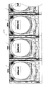
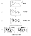
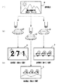
次に、特別のデモンストレーション表示の表示例を説明する。図8は、特別のデモンストレーション表示の表示例を示す遊技機設置島200の正面図である。図8に示すように、遊技機設置島200には、パチンコ遊技機1が複数台並べて配置されている。   Next, a display example of a special demonstration display will be described. FIG. 8 is a front view of the gaming machine installation island 200 showing a display example of a special demonstration display. As shown in FIG. 8, a plurality of pachinko gaming machines 1 are arranged side by side on the gaming machine installation island 200.

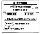
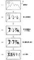
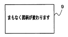
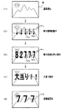
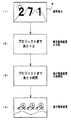
本実施の形態においては、客待ちデモンストレーションとしてのデモンストレーション表示を行なう演出として、現時刻が所定の特別デモ実行時刻でないときに実行する通常のデモンストレーション表示の演出と、現時刻が所定の特別デモ実行時刻となったときにのみ実行する特別のデモンストレーション表示の演出とが行なわれる。以下においては、デモンストレーション表示をデモ表示と略称で示す場合があり、特別のデモンストレーション表示を特別デモ表示と略称で示す場合がある。特別のデモンストレーション表示は、図8に示すように、各パチンコ遊技機1の変動表示装置9において、予め設定された特別のデモンストレーション表示の開始時刻となったときに、予め定められた特別デモ表示用画像の表示を開始させることにより行なわれる。特別のデモンストレーション表示は、予め設定された実行時間(たとえば、10分間)が経過するまで継続して行なわれる。   In the present embodiment, as an effect of performing a demonstration display as a customer waiting demonstration, an effect of a normal demonstration display that is executed when the current time is not a predetermined special demonstration execution time, and a current time is a predetermined special demonstration execution time There will be a special demonstration display that will only be performed when In the following, the demonstration display may be abbreviated as a demonstration display, and the special demonstration display may be abbreviated as a special demonstration display. As shown in FIG. 8, the special demonstration display is for a special demonstration display that is set in advance when the preset special demonstration display start time is reached in the variable display device 9 of each pachinko gaming machine 1. This is done by starting display of an image. The special demonstration display is continuously performed until a preset execution time (for example, 10 minutes) elapses.

また、各遊技機設置島200で特別のデモンストレーション表示が行なわれるときには、各パチンコ遊技機1の装飾ランプ25、天枠ランプ28a、左枠ランプ28b、および、右枠ランプ28cが、所定の発光パターンで点灯動作させられる。この特別のデモンストレーション表示における発光パターンは、特別のデモンストレーション表示特有のものであってもよく、他の演出の実行時に用いられる発光パターンと共通に用いられるものであってもよい。つまり、特別のデモンストレーション表示における発光パターンは、特別のデモンストレーション表示であることが識別できるようなものであればどのような発光パターンを用いてもよい。このような発光パターンとしては、単位時間(たとえば、1秒間)ごとに変化するものが望ましく、また、単位時間ごとに比較しやすいものが好ましい。たとえば、このような発光パターンとしては、ある種のメーターが増加または減少していく発光パターン、色が漸時変化する発光パターン、および、単なる時刻を表示する時計のような発光パターンのいずれか1つ、または、いずれかの組合せであってもよい。   Further, when a special demonstration display is performed on each gaming machine installation island 200, the decoration lamp 25, the top frame lamp 28a, the left frame lamp 28b, and the right frame lamp 28c of each pachinko gaming machine 1 have a predetermined light emission pattern. Can be turned on. The light emission pattern in the special demonstration display may be unique to the special demonstration display, or may be used in common with the light emission pattern used when other effects are performed. That is, any light emission pattern may be used as the light emission pattern in the special demonstration display as long as it can be identified as the special demonstration display. As such a light emission pattern, one that changes every unit time (for example, 1 second) is desirable, and one that is easy to compare every unit time is preferable. For example, as such a light emission pattern, any one of a light emission pattern in which a certain meter increases or decreases, a light emission pattern in which a color gradually changes, and a light emission pattern such as a clock that displays a simple time. Or any combination thereof.

なお、特別のデモンストレーション表示は、変動表示装置9において前述のような画像の表示とランプの発光とを行なう制御に加えて、予め定められた音を出力する制御を行なうものであってもよい。   Note that the special demonstration display may be a control for outputting a predetermined sound in addition to the control for displaying the image and the light emission of the lamp as described above in the variable display device 9.

特別のデモンストレーション表示は、予め設定された時刻となったときに各パチンコ遊技機1において一斉に実行されるため、各遊技機設置島200においては、予め設定された時刻となったときに各遊技機設置島200で列設されたパチンコ遊技機1において一斉に実行される一斉演出となる。 Since the special demonstration display is executed simultaneously in each pachinko gaming machine 1 when a preset time is reached, each game machine installation island 200 has each game when the preset time is reached. the simultaneous production to be performed in unison have you in the pachinko gaming machine 1, which is the column set in the machine installation island 200.

このような特別のデモンストレーション表示を行なう制御は、各パチンコ遊技機1に設けられたリアルタイムクロック353の計時値に基づいてパチンコ遊技機1ごとに行なわれるため、同時に開始されないとき(同期して実行されないとき)には、パチンコ遊技機1相互間でリアルタイムクロック353の計時値にずれ(狂い)が生じていると判断することができる。これにより、たとえば遊技場の営業時間外にこのような特別のデモンストレーション表示を行なうことに基づいて、各遊技機設置島200においてパチンコ遊技機1相互間でリアルタイムクロック353の計時値にずれが生じているか否かを判断し、ずれが生じていると判断したときには、後述するように、日時データ出力装置300(図15)を用いて、各パチンコ遊技機1のリアルタイムクロック353の計時値を日時データに基づいて設定し直すようにすれば、そのような計時値のずれを解消することができる。また、各遊技機設置島200においてパチンコ遊技機1相互間でリアルタイムクロック353の計時値にずれが生じていると判断したときには、後述するように、遊技場の店員が手動で各パチンコ遊技機1のリアルタイムクロック353の計時値を設定し直すようにしてもよい。   The control for performing such a special demonstration display is performed for each pachinko gaming machine 1 based on the time value of the real-time clock 353 provided in each pachinko gaming machine 1 and is therefore not started simultaneously (not executed synchronously). Time), it can be determined that there is a shift (inconsistency) in the time value of the real-time clock 353 between the pachinko gaming machines 1. Accordingly, for example, on the basis of performing such a special demonstration display outside the business hours of the game hall, the time value of the real-time clock 353 is shifted between the pachinko gaming machines 1 on each gaming machine installation island 200. If it is determined whether or not there is a deviation, the time value of the real-time clock 353 of each pachinko gaming machine 1 is set to the date / time data using the date / time data output device 300 (FIG. 15), as will be described later. If the setting is reset on the basis of the above, it is possible to eliminate such a shift in the measured value. In addition, when it is determined that there is a deviation in the timekeeping value of the real-time clock 353 between the pachinko gaming machines 1 on each gaming machine installation island 200, the store clerk of the game hall manually controls each pachinko gaming machine 1 as described later. The time value of the real time clock 353 may be reset.

このように、各遊技機設置島200に設置された各パチンコ遊技機1におけるリアルタイムクロック353の計時値のずれを解消することができれば、前述したような遊技場の営業時間内において各遊技機設置島200で行なわれる一斉演出を、各遊技機設置島200に設けられた全パチンコ遊技機1において同期させて行なうことができるようになる。   In this way, if it is possible to eliminate the time difference of the real-time clock 353 in each pachinko gaming machine 1 installed on each gaming machine installation island 200, each gaming machine is installed within the business hours as described above. The simultaneous production performed on the island 200 can be performed synchronously in all the pachinko gaming machines 1 provided on each gaming machine installation island 200.

また、このような特別のデモンストレーション表示を、遊技場の営業時間内において各遊技機設置島200で行なうことにより、パチンコ遊技機1により行なわれる演出の面白みを向上させることができ、遊技者の興趣を向上させることができる。   In addition, by performing such a special demonstration display on each gaming machine installation island 200 during the business hours of the game hall, it is possible to improve the fun of the performance performed by the pachinko gaming machine 1 and to enhance the interest of the player. Can be improved.

また、特別のデモンストレーション表示の代わりに、特別デモ表示用画像のような画像を表示しない特別デモンストレーションとしての特別デモ演出を行なうようにしてもよい。このような特別デモ演出としては、各パチンコ遊技機1の装飾ランプ25、天枠ランプ28a、左枠ランプ28b、および、右枠ランプ28cを所定の発光パターンで点灯動作させられる。特別デモ演出は、装飾ランプ25、天枠ランプ28a、左枠ランプ28b、および、右枠ランプ28c以外のランプを用いて行なうようにしてもよい。また、特別デモ演出は、ランプを動作させる制御に加えて、予め定められた音を出力する制御を行なうものであってもよい。また、特別デモ演出は、ランプを動作させる制御に加えて、変動表示装置9において予め定められた画像を表示する制御(たとえば、その時点で変動表示装置9に表示されている変動表示中または非変動表示中の画像に、予め定められた特別デモ演出用の画像を重畳して表示する制御)を行なうものであってもよい。また、特別デモ演出は、変動表示装置9において予め定められた画像を表示する制御のみを行なうものであってもよい。   Further, instead of a special demonstration display, a special demonstration effect may be performed as a special demonstration in which an image such as a special demonstration display image is not displayed. As such a special demonstration effect, the decoration lamp 25, the top frame lamp 28a, the left frame lamp 28b, and the right frame lamp 28c of each pachinko gaming machine 1 are turned on with a predetermined light emission pattern. The special demonstration effect may be performed using a lamp other than the decorative lamp 25, the top frame lamp 28a, the left frame lamp 28b, and the right frame lamp 28c. The special demonstration effect may be a control for outputting a predetermined sound in addition to the control for operating the lamp. In addition to the control for operating the lamp, the special demonstration effect is a control for displaying a predetermined image on the variable display device 9 (for example, during or without the variable display displayed on the variable display device 9 at that time). A control for superimposing and displaying a predetermined image for special demonstration effect on the image being displayed in a variable manner may be performed. In addition, the special demonstration effect may be one in which only control for displaying a predetermined image on the variable display device 9 is performed.

このような特別デモ演出を、遊技場の営業時間内において各遊技機設置島200で行なうことにより、パチンコ遊技機1により行なわれる演出の面白みを向上させることができ、遊技者の興趣を向上させることができる。   By performing such a special demonstration effect on each gaming machine installation island 200 during the business hours of the game hall, the fun of the performance performed by the pachinko gaming machine 1 can be improved, and the interest of the player is improved. be able to.

なお、特別デモ演出が実行されている期間中には、それ以外の期間と比べて、前述の特別リーチの出現率を増加させる制御、大当り予告の出現率を増加させる制御、および、大当り予告の種類を変更する制御のうち、いずれか1つ、または、いずれかの組合せを実行する等、特有の制御を行なうようにしてもよい。   In addition, during the period when the special demonstration performance is being executed, the control for increasing the appearance rate of the special reach, the control for increasing the appearance rate of the jackpot notice, A unique control such as executing any one or any combination of the types of control may be performed.

また、特別のデモンストレーション表示の実行時間の実行中において、始動入賞が生じて変動表示が実行されるときには、特別のデモンストレーション表示が終了させられ、特別演出として、ミッション演出と呼ばれる演出が行なわれる。ここで、ミッション演出について説明する。ミッション演出は、予め遊技者に有効期間としてのミッション期間と、所定の演出(たとえば、特定のキャラクタを出現させる演出等)とをミッションの達成条件として報知(提示)し、報知したミッション期間内において報知(提示)した所定の演出が実行されると、所定の大当り遊技状態(たとえば、提示した種類の大当り(確変大当りまたは通常大当り)のような特定の大当りに限定してもよく、種類を問わないいずれかの大当り遊技状態であってもよい)に制御される特別な演出である。ミッション達成条件が成立してミッションが達成されたときには、所定の大当りとなる等の遊技者にとって有利な状態に制御される。 In addition, during the execution time of the special demonstration display, when the start prize is generated and the variable display is executed, the special demonstration display is ended, and an effect called a mission effect is performed as a special effect. Here, the mission effect will be described. Mission director has a mission period as an active period in advance a player, a predetermined effect (e.g., effect, etc. which revealed out of the specific character) informs (presented) and as benchmarks mission, informing the inside of the transmission period When the predetermined effect notified (presented) is executed, the game may be limited to a specific jackpot such as a predetermined jackpot gaming state (for example, the type of jackpot presented (probable jackpot or normal jackpot), This is a special performance controlled by any of the big hit gaming states regardless of the game. When the mission achievement condition is satisfied and the mission is achieved, the player is controlled in a state advantageous to the player such as a predetermined big hit.

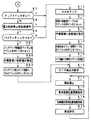
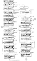
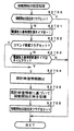
次にパチンコ遊技機1の動作について説明する。図9および図10は、パチンコ遊技機1に対して電力供給が開始され遊技制御用マイクロコンピュータ560へのリセット信号がハイレベルになったことに応じて遊技制御用マイクロコンピュータ560のCPU56が実行するメイン処理を示すフローチャートである。リセット信号が入力されるリセット端子の入力レベルがハイレベルになると、遊技制御用マイクロコンピュータ560のCPU56は、プログラムの内容が正当か否かを確認するための処理であるセキュリティチェック処理を実行した後、S1以降のメイン処理を開始する。メイン処理において、CPU56は、まず、必要な初期設定を行なう。   Next, the operation of the pachinko gaming machine 1 will be described. 9 and 10 are executed by the CPU 56 of the game control microcomputer 560 in response to the start of power supply to the pachinko gaming machine 1 and the reset signal to the game control microcomputer 560 becoming high level. It is a flowchart which shows a main process. When the input level of the reset terminal to which the reset signal is input becomes a high level, the CPU 56 of the game control microcomputer 560 executes a security check process that is a process for confirming whether the contents of the program are valid. The main processing after S1 is started. In the main process, the CPU 56 first performs necessary initial settings.

初期設定処理において、CPU56は、まず、割込禁止に設定する(ステップS(以下、単にSという)1)。次に、マスク可能割込の割込モードを設定し(S2)、スタックポインタにスタックポインタ指定アドレスを設定する(S3)。なお、S2では、遊技制御用マイクロコンピュータ560の特定レジスタ(Iレジスタ)の値(1バイト)と内蔵デバイスが出力する割込ベクタ(1バイト:最下位ビット0)から合成されるアドレスが、割込番地を示すモードに設定する。また、マスク可能な割込が発生すると、CPU56は、自動的に割込禁止状態に設定するとともに、プログラムカウンタの内容をスタックにセーブする。   In the initial setting process, the CPU 56 first sets the interrupt prohibition (step S (hereinafter simply referred to as S) 1). Next, an interrupt mode for maskable interrupts is set (S2), and a stack pointer designation address is set in the stack pointer (S3). In S2, an address synthesized from the value (1 byte) of the specific register (I register) of the game control microcomputer 560 and the interrupt vector (1 byte: least significant bit 0) output from the built-in device is Set to the mode that indicates the included address. When a maskable interrupt occurs, the CPU 56 automatically sets the interrupt disabled state and saves the contents of the program counter in the stack.

次いで、内蔵デバイスレジスタの設定(初期化)を行なう(S4)。S4の処理によって、内蔵デバイス(内蔵周辺回路)であるCTC(カウンタ/タイマ)およびPIO(パラレル入出力ポート)の設定(初期化)がなされる。   Next, the built-in device register is set (initialized) (S4). By the process of S4, the CTC (counter / timer) and the PIO (parallel input / output port), which are built-in devices (built-in peripheral circuits), are set (initialized).

この実施の形態で用いられる遊技制御用マイクロコンピュータ560は、I/Oポート(PIO)およびタイマ/カウンタ回路(CTC)504も内蔵している。   The game control microcomputer 560 used in this embodiment also incorporates an I / O port (PIO) and a timer / counter circuit (CTC) 504.

次に、入力ポート1のビット0の状態によって電源断信号がオフ状態になっているか否かを確認する(S5)。パチンコ遊技機1に対する電力供給が開始されたときに、+5V電源等の各種電源の出力電圧は徐々に規定値に達するのであるが、S5の処理によって、すなわち、電源断信号が出力されていない(ハイレベルになっている)ことを確認することによりCPU56は電源電圧が安定したことを確認することができる。   Next, it is confirmed whether or not the power-off signal is in an OFF state according to the state of bit 0 of the input port 1 (S5). When power supply to the pachinko gaming machine 1 is started, the output voltage of various power sources such as a + 5V power source gradually reaches a specified value, but the power-off signal is not output by the process of S5 (that is, By confirming that the power supply voltage is high, the CPU 56 can confirm that the power supply voltage is stable.

電源断信号がオン状態である場合には、CPU56は、所定期間(たとえば、0.1秒)の遅延時間の後に(S80)、再度、電源断信号がオフ状態になっているか否かを確認する。電源断信号がオフ状態になっている場合には、RAM55をアクセス可能状態に設定し(S6)、クリア信号のチェック処理に移行する。   If the power-off signal is in the on state, the CPU 56 checks again whether or not the power-off signal is in the off state after a delay time of a predetermined period (for example, 0.1 second) (S80). To do. If the power-off signal is off, the RAM 55 is set to an accessible state (S6), and the process proceeds to a clear signal check process.

なお、電源断信号がオフ状態である場合に、遊技の進行を制御する遊技装置制御処理(遊技制御処理)の開始タイミングをソフトウェアで遅らせるためのソフトウェア遅延処理を実行するようにしてもよい。そのようなソフトウェア遅延処理によって、ソフトウェア遅延処理を実行しない場合に比べて、遊技制御処理の開始タイミングを遅延させることができる。遅延処理を実行したときには、他の制御基板(たとえば、払出制御基板37)に対して、遊技制御基板(主基板31)が送信するコマンドを他の制御基板のマイクロコンピュータが受信できないという状況が発生することを防止できる。   When the power-off signal is in the off state, software delay processing for delaying the start timing of the gaming device control processing (game control processing) for controlling the progress of the game by software may be executed. By such software delay processing, the start timing of the game control processing can be delayed as compared with the case where the software delay processing is not executed. When the delay process is executed, a situation occurs in which the microcomputer of the other control board cannot receive the command transmitted from the game control board (main board 31) to the other control board (for example, the payout control board 37). Can be prevented.

次いで、CPU56は、クリアスイッチ912がオンされているか否かを確認する(S7)。なお、CPU56は、入力ポート0を介して1回だけクリア信号の状態を確認するようにしてもよいが、複数回クリア信号の状態を確認するようにしてもよい。たとえば、クリア信号の状態がオフ状態であることを確認したら、所定時間(たとえば、0.1秒)の遅延時間をおいた後、クリア信号の状態を再確認する。そのときにクリア信号の状態がオン状態であることを確認したら、クリア信号がオン状態になっていると判定する。また、このときにクリア信号の状態がオフ状態であることを確認したら、所定時間の遅延時間をおいた後、再度、クリア信号の状態を再確認するようにしてもよい。ここで、再確認の回数は、1回または2回に限られず、3回以上であってもよい。また、2回チェックして、チェック結果が一致していなかったときにもう一度確認するようにしてもよい。   Next, the CPU 56 checks whether or not the clear switch 912 is turned on (S7). Note that the CPU 56 may confirm the state of the clear signal only once via the input port 0, but may confirm the state of the clear signal a plurality of times. For example, if it is confirmed that the state of the clear signal is OFF, a delay time of a predetermined time (for example, 0.1 seconds) is set, and then the state of the clear signal is reconfirmed. If it is confirmed that the clear signal is in the on state at that time, it is determined that the clear signal is in the on state. Further, at this time, if it is confirmed that the state of the clear signal is the off state, after a delay time of a predetermined time, the state of the clear signal may be confirmed again. Here, the number of reconfirmations is not limited to once or twice, but may be three or more times. It is also possible to check twice and check again when the check results do not match.

S7でクリアスイッチ912がオンでない場合には、パチンコ遊技機1への電力供給が停止したときにバックアップRAM領域のデータ保護処理(たとえばパリティデータの付加等の電力供給停止時処理)が行なわれたか否かを確認する(S8)。この実施の形態では、電力供給の停止が生じた場合には、バックアップRAM領域のデータを保護するための処理が行なわれている。そのような電力供給停止時処理が行なわれていたことを確認した場合には、CPU56は、電力供給停止時処理が行なわれた、すなわち電力供給停止時の制御状態が保存されていると判定する。電力供給停止時処理が行なわれていないことを確認した場合には、CPU56は初期化処理を実行する。   If the clear switch 912 is not turned on in S7, was the data protection process in the backup RAM area (for example, when the power supply stopped such as adding parity data) performed when the power supply to the pachinko gaming machine 1 was stopped? It is confirmed whether or not (S8). In this embodiment, when power supply is stopped, processing for protecting data in the backup RAM area is performed. When it is confirmed that such power supply stop processing has been performed, the CPU 56 determines that the power supply stop processing has been performed, that is, the control state at the time of power supply stop is stored. . When it is confirmed that the power supply stop process is not performed, the CPU 56 executes an initialization process.

電力供給停止時処理が行なわれていたか否かは、電力供給停止時処理においてバックアップRAM領域に保存されるバックアップ監視タイマの値が、電力供給停止時処理を実行したことに応じた値(たとえば2)になっているか否かによって確認される。なお、そのような確認の仕方は一例であって、たとえば、電力供給停止時処理においてバックアップフラグ領域に電力供給停止時処理を実行したことを示すフラグをセットし、S8において、そのフラグがセットされていることを確認したら電力供給停止時処理が行なわれたと判定してもよい。   Whether or not the power supply stop process has been performed is determined based on the value of the backup monitoring timer stored in the backup RAM area in the power supply stop process depending on the execution of the power supply stop process (for example, 2). ) Is confirmed by whether or not. Note that such a confirmation method is merely an example. For example, a flag indicating that the power supply stop process has been executed is set in the backup flag area in the power supply stop process, and the flag is set in S8. If it is confirmed that the power supply is stopped, it may be determined that the power supply stop process has been performed.

電力供給停止時の制御状態が保存されていると判定したら、CPU56は、バックアップRAM領域のデータチェック(この例ではパリティチェック)を行なう(S9)。この実施の形態では、クリアデータ(00)をチェックサムデータエリアにセットし、チェックサム算出開始アドレスをポインタにセットする。また、チェックサムの対象になるデータ数に対応するチェックサム算出回数をセットする。そして、チェックサムデータエリアの内容とポインタが指すRAM領域の内容との排他的論理和を演算する。演算結果をチェックサムデータエリアにストアするとともに、ポインタの値を1増やし、チェックサム算出回数の値を1減算する。以上の処理が、チェックサム算出回数の値が0になるまで繰返される。チェックサム算出回数の値が0になったら、CPU56は、チェックサムデータエリアの内容の各ビットの値を反転し、反転後のデータをチェックサムにする。   If it is determined that the control state at the time of stopping power supply is stored, the CPU 56 performs data check (parity check in this example) in the backup RAM area (S9). In this embodiment, clear data (00) is set in the checksum data area, and the checksum calculation start address is set in the pointer. Also, the number of checksum calculations corresponding to the number of data to be checksum is set. Then, the exclusive OR of the contents of the checksum data area and the contents of the RAM area pointed to by the pointer is calculated. The calculation result is stored in the checksum data area, the pointer value is incremented by 1, and the checksum calculation count value is decremented by 1. The above processing is repeated until the value of the checksum calculation count becomes zero. When the value of the checksum calculation count becomes 0, the CPU 56 inverts the value of each bit of the contents of the checksum data area and uses the inverted data as the checksum.

電力供給停止時処理において、上記の処理と同様の処理によってチェックサムが算出され、チェックサムはバックアップRAM領域に保存されている。S9では、算出したチェックサムと保存されているチェックサムとを比較する。不測の停電等の電力供給停止が生じた後に復旧した場合には、バックアップRAM領域のデータは保存されているはずであるから、チェック結果(比較結果)は正常(一致)になる。チェック結果が正常でないということは、バックアップRAM領域のデータが、電力供給停止時のデータとは異なっている可能性があることを意味する。そのような場合には、内部状態を電力供給停止時の状態に戻すことができないので、電力供給の停止からの復旧時でない電源投入時に実行される初期化処理(S10〜S14の処理)を実行する。   In the power supply stop process, a checksum is calculated by the same process as described above, and the checksum is stored in the backup RAM area. In S9, the calculated checksum is compared with the stored checksum. When the power supply is stopped after an unexpected power failure or the like, the data in the backup RAM area should be saved, so the check result (comparison result) is normal (matched). That the check result is not normal means that the data in the backup RAM area may be different from the data when the power supply is stopped. In such a case, since the internal state cannot be returned to the state when the power supply is stopped, the initialization process (the process of S10 to S14) that is executed when the power is turned on but not when the power supply is stopped is executed. To do.

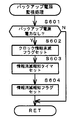
チェック結果が正常であれば、CPU56は、遊技制御手段の内部状態と演出制御手段等の電気部品制御手段の制御状態を電力供給停止時の状態に戻すための遊技状態復旧処理を行なう。具体的には、ROM54に格納されているバックアップ時設定テーブルの先頭アドレスをポインタに設定し(S91)、バックアップ時設定テーブルの内容を順次作業領域(RAM55内の領域)に設定する(S92)。作業領域はバックアップ電源によって電源バックアップされている。バックアップ時設定テーブルには、作業領域のうち初期化してもよい領域についての初期化データが設定されている。S91およびS92の処理によって、作業領域のうち初期化してはならない部分については、保存されていた内容がそのまま残る。初期化してはならない部分とは、たとえば、電力供給停止前の遊技状態を示すデータ(特別図柄プロセスフラグ等)、出力ポートの出力状態が保存されている領域(出力ポートバッファ)、未払出賞球数を示すデータが設定されている部分等である。   If the check result is normal, the CPU 56 performs a game state restoration process for returning the internal state of the game control means and the control state of the electrical component control means such as the effect control means to the state when the power supply is stopped. Specifically, the start address of the backup setting table stored in the ROM 54 is set as a pointer (S91), and the contents of the backup setting table are sequentially set in the work area (area in the RAM 55) (S92). The work area is backed up by a backup power source. In the backup setting table, initialization data for an area that may be initialized in the work area is set. By the processing of S91 and S92, the saved contents remain as they are in the portion of the work area that should not be initialized. The parts that should not be initialized include, for example, data indicating the gaming state before the power supply is stopped (special symbol process flag, etc.), the area where the output state of the output port is saved (output port buffer), unpaid prize balls This is a portion where data indicating a number is set.

また、CPU56は、ROM54に格納されているバックアップ時コマンド送信テーブルの先頭アドレスをポインタに設定し(S93)、S15に移行する。   Further, the CPU 56 sets the head address of the backup command transmission table stored in the ROM 54 as a pointer (S93), and proceeds to S15.

初期化処理では、CPU56は、まず、RAMクリア処理を行なう(S10)。なお、RAM55の全領域を初期化せず、所定のデータをそのままにしてもよい。また、ROM54に格納されている初期化時設定テーブルの先頭アドレスをポインタに設定し(S11)、初期化時設定テーブルの内容を順次作業領域に設定する(S12)。   In the initialization process, the CPU 56 first performs a RAM clear process (S10). Note that the predetermined data may be left as it is without initializing the entire area of the RAM 55. The initial address of the initialization setting table stored in the ROM 54 is set as a pointer (S11), and the contents of the initialization setting table are sequentially set in the work area (S12).

S11およびS12の処理によって、たとえば、普通図柄判定用乱数カウンタ、普通図柄判定用バッファ、特別図柄バッファ、総賞球数格納バッファ、特別図柄プロセスフラグ、賞球中フラグ、球切れフラグ等制御状態に応じて選択的に処理を行なうためのフラグに初期値が設定される。また、出力ポートバッファにおける接続確認信号を出力する出力ポートに対応するビットがセット(接続確認信号のオン状態に対応)される。   By the processing of S11 and S12, for example, a normal symbol determination random number counter, a normal symbol determination buffer, a special symbol buffer, a total prize ball number storage buffer, a special symbol process flag, an award ball flag, an out of ball flag, etc. Accordingly, an initial value is set in a flag for selectively performing processing. In addition, a bit corresponding to the output port that outputs the connection confirmation signal in the output port buffer is set (corresponding to the ON state of the connection confirmation signal).

また、CPU56は、ROM54に格納されている初期化時コマンド送信テーブルの先頭アドレスをポインタに設定し(S13)、その内容にしたがってサブ基板を初期化するための初期化コマンドをサブ基板に送信する処理を実行する(S14)。初期化コマンドとして、変動表示装置9に表示される初期図柄を示すコマンドや払出制御基板37への初期化コマンド等を使用することができる。   Further, the CPU 56 sets the start address of the initialization command transmission table stored in the ROM 54 as a pointer (S13), and transmits an initialization command for initializing the sub board according to the contents to the sub board. Processing is executed (S14). As an initialization command, a command indicating an initial symbol displayed on the variable display device 9, an initialization command to the payout control board 37, or the like can be used.

そして、CPU56は、所定時間(たとえば2ms)ごとに定期的にタイマ割込がかかるように遊技制御用マイクロコンピュータ560に内蔵されているCTCのレジスタの設定を行なうタイマ割込設定処理を実行する(S15)。すなわち、初期値としてたとえば2msに相当する値が所定のレジスタ(時間定数レジスタ)に設定される。この実施の形態では、2msごとに定期的にタイマ割込がかかるとする。   Then, the CPU 56 executes a timer interrupt setting process for setting a CTC register built in the game control microcomputer 560 so that a timer interrupt is periodically taken every predetermined time (for example, 2 ms) ( S15). That is, for example, a value corresponding to 2 ms is set in a predetermined register (time constant register) as an initial value. In this embodiment, it is assumed that a timer interrupt is periodically taken every 2 ms.

タイマ割込の設定が完了すると、CPU56は、表示図柄乱数更新処理(S17)および初期値決定用乱数更新処理(S18)を繰り返し実行する。CPU56は、表示図柄乱数更新処理および初期値決定用乱数更新処理が実行されるときには割込禁止状態にして(S16)、表示図柄乱数更新処理および初期値決定用乱数更新処理の実行が終了すると割込許可状態にする(S19)。   When the timer interrupt setting is completed, the CPU 56 repeatedly executes the display symbol random number update process (S17) and the initial value determination random number update process (S18). The CPU 56 disables the interrupt when the display symbol random number update process and the initial value determination random number update process are executed (S16), and when the execution of the display symbol random number update process and the initial value determination random number update process ends, the CPU 56 Is set to the permitted state (S19).

なお、表示図柄乱数とは、特別図柄表示器8の表示を決定するための乱数である。この実施の形態では、表示図柄乱数として、特別図柄の変動パターンを決定するための変動パターン決定用乱数や、大当りを発生させない場合にリーチとするか否かを決定するためのリーチ判定用乱数が用いられる。また、表示図柄乱数更新処理とは、表示図柄乱数を発生するためのカウンタのカウント値を更新する処理である。   The display symbol random number is a random number for determining the display of the special symbol indicator 8. In this embodiment, as the display symbol random number, there are a variation pattern determining random number for determining a variation pattern of a special symbol, and a reach determination random number for determining whether or not to reach when a big hit is not generated. Used. The display symbol random number update process is a process for updating the count value of the counter for generating the display symbol random number.

また、初期値決定用乱数更新処理とは、初期値決定用乱数を発生するためのカウンタのカウント値を更新する処理である。初期値決定用乱数とは、大当りの種類を決定するための判定用乱数(たとえば、大当りを発生させる特別図柄を決定するための大当り図柄決定用乱数や、普通図柄に基づく当りを発生させるか否かを決定するための普通図柄当り判定用乱数)を発生するためのカウンタ(判定用乱数発生カウンタ)等のカウント値の初期値を決定するための乱数である。後述する遊技制御処理(遊技制御用マイクロコンピュータが、パチンコ遊技機1に設けられている変動表示装置9、可変入賞球装置15、球払出装置97等の遊技用の装置を、自身で制御する処理、または他のマイクロコンピュータに制御させるために指令信号を送信する処理、遊技装置制御処理ともいう)において、判定用乱数発生カウンタのカウント値が1周すると、そのカウンタに初期値が設定される。   The initial value determining random number update process is a process of updating the count value of the counter for generating the initial value determining random number. A random number for determining the initial value is a random number for determining the type of jackpot (for example, whether or not to generate a jackpot symbol determining random number for determining a special symbol for generating a jackpot or a hit based on a normal symbol) This is a random number for determining an initial value of a count value, such as a counter (determination random number generation counter) for generating a normal random number for determination per symbol). Game control processing described later (a game control microcomputer controls itself a game device such as a variable display device 9, a variable winning ball device 15 and a ball payout device 97 provided in the pachinko gaming machine 1) In a process for transmitting a command signal to cause another microcomputer to control, or a game machine control process), when the count value of the determination random number generation counter makes one round, an initial value is set in the counter.

なお、表示図柄乱数更新処理および初期値決定用乱数更新処理が実行されるときに割込禁止状態にされるのは、表示図柄乱数更新処理および初期値決定用乱数更新処理が後述するタイマ割込処理でも実行される(すなわち、タイマ割込処理のS25,S26でも同じ処理が実行される)ことから、タイマ割込処理における処理と競合してしまうのを避けるためである。すなわち、S17,S18の処理中にタイマ割込が発生してタイマ割込処理中で表示図柄乱数や初期値決定用乱数を発生するためのカウンタのカウント値を更新してしまったのでは、カウント値の連続性が損なわれる場合がある。しかし、S17,S18の処理中では割込禁止状態にしておけば、そのような不都合が生ずることはない。   Note that when the display symbol random number update process and the initial value determination random number update process are executed, the interrupt is disabled. The display symbol random number update process and the initial value determination random number update process are described later. This is to avoid contention with the process in the timer interrupt process because the process is also executed in the process (that is, the same process is also executed in S25 and S26 of the timer interrupt process). That is, if a timer interrupt is generated during the processing of S17 and S18 and the counter value for generating the display symbol random number and the initial value determining random number is updated during the timer interrupt processing, The continuity of values may be impaired. However, such an inconvenience does not occur if the interrupt is prohibited during the processing of S17 and S18.

以上のように、遊技場員等は、クリアスイッチ912をオン状態してクリア信号が出力される状態にしながらパチンコ遊技機1に対する電力供給を開始する(たとえば電源スイッチ911をオンする)ことによって、容易に初期化処理を実行させることができる。すなわち、RAMクリア等を行なうことができる。   As described above, the game hall staff or the like starts power supply to the pachinko gaming machine 1 while turning on the clear switch 912 and outputting a clear signal (for example, turning on the power switch 911). The initialization process can be easily executed. That is, RAM clear or the like can be performed.

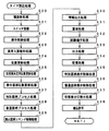
次に、遊技制御処理について説明する。図11は、タイマ割込処理を示すフローチャートである。メイン処理の実行中に、具体的には、S16〜S19のループ処理の実行中における割込許可になっている期間において、タイマ割込が発生すると、遊技制御用マイクロコンピュータ560のCPU56は、タイマ割込の発生に応じて起動されるタイマ割込処理において遊技制御処理を実行する。タイマ割込処理において、CPU56は、まず、電源断信号が出力されたか否か(オン状態になったか否か)を検出する電源断処理(電源断検出処理)を実行する(S20)。次いで、スイッチ回路58を介して、ゲートスイッチ32a、始動口スイッチ14a、カウントスイッチ23および入賞口スイッチ29a,30a,33a,39a等のスイッチの検出信号を入力し、それらの状態判定を行なう(スイッチ処理:S21)。具体的には、各スイッチの検出信号を入力する入力ポートの状態がオン状態であれば、各スイッチに対応して設けられているスイッチタイマの値を+1する。   Next, the game control process will be described. FIG. 11 is a flowchart showing the timer interrupt process. When a timer interrupt occurs during execution of the main process, specifically, during a period when interrupts are permitted during the execution of the loop process of S16 to S19, the CPU 56 of the game control microcomputer 560 A game control process is executed in a timer interrupt process activated in response to the occurrence of an interrupt. In the timer interrupt process, the CPU 56 first executes a power-off process (power-off detection process) that detects whether or not a power-off signal has been output (whether or not an on-state has been turned on) (S20). Next, detection signals from switches such as the gate switch 32a, the start port switch 14a, the count switch 23, and the winning port switches 29a, 30a, 33a, and 39a are input through the switch circuit 58, and the state of these is determined (switches). Process: S21). Specifically, if the state of the input port for inputting the detection signal of each switch is ON, the value of the switch timer provided corresponding to each switch is incremented by one.

次いで、CPU56は、特別図柄表示器8や、普通図柄表示器10、状態表示灯等の各種表示器へのDG信号の出力やクリアを行なう表示制御処理を実行する(S22)。次いで、CPU56は、大入賞口への異常入賞を検出したことを報知する異常入賞報知処理を実行する(S23)。具体的には、後述する特別図柄プロセス処理において大入賞口を開放する前である(具体的には、後述するS300〜S303の処理の段階である)にもかかわらず、カウントスイッチ23のオンを検出した場合に、大入賞口への異常入賞を検出したと判定し報知する制御を行なう。   Next, the CPU 56 executes a display control process for outputting and clearing the DG signal to various displays such as the special symbol display 8, the normal symbol display 10, and the status indicator (S22). Next, the CPU 56 executes an abnormal winning notification process for notifying that an abnormal winning to the special winning opening has been detected (S23). Specifically, the count switch 23 is turned on in spite of the fact that it is before opening the special winning opening in the special symbol process process to be described later (specifically, at the stage of processing of S300 to S303 to be described later). If it is detected, control is performed to determine and notify that an abnormal winning in the special winning opening has been detected.

次に、遊技制御に用いられる各判定用乱数を生成するための各カウンタのカウント値を更新する処理を行なう(乱数更新処理:S24)。また、CPU56は、初期値決定用乱数を生成するためのカウンタのカウント値を更新する処理を行なう(初期値決定用乱数更新処理:S25)。さらに、CPU56は、表示図柄乱数を生成するためのカウンタのカウント値を更新する処理を行なう(表示図柄乱数更新処理:S26)。   Next, a process of updating the count value of each counter for generating each determination random number used for game control is performed (random number update process: S24). Further, the CPU 56 performs a process of updating the count value of the counter for generating the initial value determining random number (initial value determining random number updating process: S25). Furthermore, CPU56 performs the process which updates the count value of the counter for producing | generating a display symbol random number (display symbol random number update process: S26).

乱数更新処理、初期値決定用乱数更新処理および表示図柄乱数更新処理を行なうと、CPU56は、特別図柄プロセス処理を行なう(S27)。特別図柄プロセス処理では、遊技状態に応じてパチンコ遊技機1を所定の順序で制御するための特別図柄プロセスフラグにしたがって該当する処理が選び出されて実行される。そして、特別図柄プロセスフラグの値は、遊技状態に応じて各処理中に更新される。また、普通図柄プロセス処理を行なう(S28)。普通図柄プロセス処理では、普通図柄表示器10の表示状態を所定の順序で制御するための普通図柄プロセスフラグにしたがって該当する処理が選び出されて実行される。そして、普通図柄プロセスフラグの値は、遊技状態に応じて各処理中に更新される。   When the random number update process, the initial value determination random number update process and the display symbol random number update process are performed, the CPU 56 performs a special symbol process (S27). In the special symbol process, the corresponding process is selected and executed according to a special symbol process flag for controlling the pachinko gaming machine 1 in a predetermined order according to the gaming state. The value of the special symbol process flag is updated during each process according to the gaming state. Further, the normal symbol process is performed (S28). In the normal symbol process, the corresponding process is selected and executed according to the normal symbol process flag for controlling the display state of the normal symbol display 10 in a predetermined order. The value of the normal symbol process flag is updated during each process according to the gaming state.

次いで、CPU56は、特別図柄の変動に同期する飾り図柄に関する演出制御コマンドをRAM55の所定の領域に設定して演出制御コマンドを送出する処理を行なう(演出図柄コマンド制御処理:S29)。なお、飾り図柄の変動が特別図柄の変動に同期するとは、変動時間(変動表示期間)が同じであることを意味する。   Next, the CPU 56 performs a process of setting an effect control command related to a decorative symbol synchronized with the change of the special symbol in a predetermined area of the RAM 55 and sending the effect control command (effect symbol command control process: S29). It should be noted that the fact that the variation of the decorative symbol is synchronized with the variation of the special symbol means that the variation time (variation display period) is the same.

次いで、CPU56は、たとえばホール管理用コンピュータに供給される大当り情報、小当り情報、始動情報、確率変動情報等のデータを出力する情報出力処理を行なう(S30)。なお、後述するように、特別図柄プロセス処理において、特別図柄プロセスフラグは「0」〜「10」の値をとり得る。また、それらの値のうち特別図柄プロセスフラグの値が「8」〜「10」である場合に、小当りに関する処理が実行される。そのため、情報出力処理において外部情報を出力するときに、小当りに関する情報であるか否かを容易に判定して小当り情報として出力することができる。たとえば、CPU56は、現在の特別図柄プロセスフラグの値が「8」以上であるか否かを確認し、「8」以上であれば、小当りに関する情報であると判定し小当り情報として出力する。また、特別図柄プロセスフラグの値が「4」〜「10」である場合に、大入賞口の開放制御を行なう処理(大当りのときと小当りのときとを含む)が実行される。そのため、情報出力処理において外部情報を出力するときに、大入賞口の開放制御に関する情報であるか否かを容易に判定して出力することができる。たとえば、CPU56は、現在の特別図柄プロセスフラグの値が「4」以上であるか否かを確認し、「4」以上であれば、大入賞口の開放制御に関する情報であると判定して外部情報を出力する。   Next, the CPU 56 performs information output processing for outputting data such as jackpot information, jackpot information, start-up information, probability variation information, etc. supplied to the hall management computer (S30). As will be described later, in the special symbol process, the special symbol process flag can take a value of “0” to “10”. Moreover, when the value of the special symbol process flag is “8” to “10” among these values, the process related to the small hit is executed. Therefore, when external information is output in the information output process, it is possible to easily determine whether or not the information is related to the small hit and output it as the small hit information. For example, the CPU 56 checks whether or not the value of the current special symbol process flag is “8” or more. If it is “8” or more, the CPU 56 determines that the information is related to the small hit and outputs it as the small hit information. . Further, when the value of the special symbol process flag is “4” to “10”, a process for controlling the opening of the big winning opening (including the case of a big win and a case of a big hit) is executed. Therefore, when outputting external information in the information output process, it is possible to easily determine whether or not the information is information related to opening control of the big prize opening. For example, the CPU 56 checks whether or not the value of the current special symbol process flag is “4” or more. If it is “4” or more, the CPU 56 determines that the information is related to the opening control of the special winning opening. Output information.

また、CPU56は、入賞口スイッチ29a,30a,33a,39a等の検出信号に基づく賞球個数の設定等を行なう賞球処理を実行する(S31)。具体的には、入賞口スイッチ29a,30a,33a,39a等がオンしたことに基づく入賞検出に応じて、払出制御基板37に賞球個数を示す賞球個数コマンド等の払出指令コマンドを出力する。払出制御基板37に搭載されている払出制御用マイクロコンピュータ370は、賞球個数を示す賞球個数コマンドの受信に応じて球払出装置97を駆動する。   Further, the CPU 56 executes prize ball processing for setting the number of prize balls based on the detection signals from the prize opening switches 29a, 30a, 33a, 39a, etc. (S31). Specifically, a payout command command such as a prize ball number command indicating the number of prize balls is output to the payout control board 37 in response to winning detection based on turning on the prize opening switches 29a, 30a, 33a, 39a, etc. . The payout control microcomputer 370 mounted on the payout control board 37 drives the ball payout device 97 in response to receiving a prize ball number command indicating the number of prize balls.

また、CPU56は、パチンコ遊技機1の制御状態をパチンコ遊技機1外部で確認できるようにするための試験信号を出力する処理である試験端子処理を実行する(S32)。また、この実施の形態では、出力ポートの出力状態に対応したRAM領域(出力ポートバッファ)が設けられているのであるが、CPU56は、出力ポート2のRAM領域におけるソレノイドに関する内容を出力ポートに出力する(S33:ソレノイド出力処理)。そして、CPU56は、保留記憶数の増減をチェックする記憶処理を実行する(S34)。   Further, the CPU 56 executes a test terminal process that is a process for outputting a test signal for enabling the control state of the pachinko gaming machine 1 to be confirmed outside the pachinko gaming machine 1 (S32). In this embodiment, a RAM area (output port buffer) corresponding to the output state of the output port is provided, but the CPU 56 outputs the contents related to the solenoid in the RAM area of the output port 2 to the output port. (S33: Solenoid output processing). Then, the CPU 56 executes a storage process for checking increase / decrease in the number of reserved storage (S34).

また、CPU56は、特別図柄プロセスフラグの値に応じて特別図柄の演出表示を行なうための特別図柄表示制御データを特別図柄表示制御データ設定用の出力バッファに設定する特別図柄表示制御処理を行なう(S35)。   Further, the CPU 56 performs special symbol display control processing for setting special symbol display control data for effect display of special symbols in an output buffer for setting special symbol display control data according to the value of the special symbol process flag ( S35).

次いで、CPU56は、普通図柄プロセスフラグの値に応じて普通図柄の演出表示を行なうための普通図柄表示制御データを普通図柄表示制御データ設定用の出力バッファに設定する普通図柄表示制御処理を行なう(S36)。   Next, the CPU 56 performs a normal symbol display control process for setting normal symbol display control data for effect display of the normal symbol in an output buffer for setting the normal symbol display control data according to the value of the normal symbol process flag ( S36).

さらに、CPU56は、各状態表示灯の表示を行なうための状態表示制御データを状態表示制御データ設定用の出力バッファに設定する状態表示灯表示処理を行なう(S37)。この場合、遊技状態が高確率状態(たとえば、確変状態)である場合には、高確率状態であることを示す状態表示灯1の表示を行なうための状態表示制御データを出力バッファに設定する。また、遊技状態が時短状態である場合には、時短状態であることを示す状態表示灯2の表示を行なうための状態表示制御データを出力バッファに設定する。   Further, the CPU 56 performs a status display lamp display process for setting status display control data for displaying each status display lamp in the output buffer for setting the status display control data (S37). In this case, when the gaming state is a high probability state (for example, a probability variation state), state display control data for displaying the state indicator lamp 1 indicating the high probability state is set in the output buffer. Further, when the gaming state is the short time state, the state display control data for displaying the status indicator lamp 2 indicating the short time state is set in the output buffer.

この実施の形態では、遊技制御処理は定期的(たとえば2msごと)に起動されることになる。なお、この実施の形態では、タイマ割込処理で遊技制御処理が実行されているが、タイマ割込処理ではたとえば割込が発生したことを示すフラグのセットのみがなされ、遊技制御処理はフラグがセットされたことに基づいてメイン処理において実行されるようにしてもよい。なお、この実施の形態において、S21〜S37の処理(S30およびS32を除く)が、遊技の進行を制御する遊技制御処理に相当する。   In this embodiment, the game control process is started periodically (for example, every 2 ms). In this embodiment, the game control process is executed by the timer interrupt process. However, in the timer interrupt process, for example, only a flag indicating that an interrupt has occurred is set. It may be executed in the main process based on the setting. In this embodiment, the processes of S21 to S37 (except S30 and S32) correspond to a game control process for controlling the progress of the game.

その後、CPU56は、割込許可状態に設定し(S38)、処理を終了する。
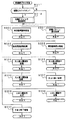
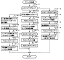
次に、メイン処理における特別図柄プロセス処理(S27)を説明する。図12は、遊技制御用マイクロコンピュータ560(具体的には、遊技制御用マイクロコンピュータ560のCPU56)が実行する特別図柄プロセス処理のプログラムの一例を示すフローチャートである。遊技制御用マイクロコンピュータ560は、特別図柄プロセス処理において、遊技盤6に設けられている始動入賞口14に遊技球が入賞したことを検出するための始動口スイッチ14aがオンしていたら、すなわち遊技球が始動入賞口14に入賞する始動入賞が発生していたら(S311)、始動口スイッチ通過処理(S312)を行なった後に、内部状態に応じて、S300〜S310のうちのいずれかの処理を行なう。始動口スイッチ14aがオンしていなければ、内部状態に応じて、S300〜S310のうちのいずれかの処理を行なう。
Thereafter, the CPU 56 sets the interrupt permitted state (S38) and ends the process.
Next, the special symbol process (S27) in the main process will be described. FIG. 12 is a flowchart showing an example of a special symbol process processing program executed by the game control microcomputer 560 (specifically, the CPU 56 of the game control microcomputer 560). In the special symbol process, the game control microcomputer 560 is turned on if the start port switch 14a for detecting that a game ball has won the start winning port 14 provided in the game board 6 is turned on, that is, a game. If a start winning that causes the ball to win the start winning opening 14 has occurred (S311), the start opening switch passing process (S312) is performed, and then any one of S300 to S310 is performed according to the internal state. Do. If the start port switch 14a is not turned on, any one of S300 to S310 is performed according to the internal state.

S122の始動口スイッチ通過処理では、始動口スイッチ14aがオンしたとき(具体的には、前述の乱数読出フラグがセットされているとき)に、RAM55の保留記憶バッファに記憶される数値データの記憶数(保留記憶数)が上限値(4)に達しているかどうか確認し、保留記憶バッファに記憶される数値データの記憶数が上限値に達していなければ、保留記憶数を示す始動入賞記憶数カウンタのカウント値を1増やす。そして、後述するような複数種類の乱数値(数値データ)を予め定められた数値データ更新手段(乱数回路またはランダムカウンタ)から抽出し、それらを保留記憶バッファの抽出順番に対応する(始動入賞記憶カウンタの値に対応する)保存領域に格納する処理が実行される。このように始動口スイッチ14aがオンし、かつ、保留記憶バッファに記憶される数値データ(保留記憶データ)の記憶数(保留記憶数)が上限値に達していないときに、乱数値となる数値データを抽出する条件が成立し、変動表示を実行するための条件、すなわち、変動表示の実行条件(始動条件)が成立することとなる。なお、始動口スイッチ14aが正常にオンした状態であるか否かの判断は、始動口スイッチ14aに対応して、始動口スイッチ14aが継続してオンしている時間を計時するタイマを設け、そのタイマ値が所定値となったときに、始動口スイッチ14aがオンした状態であると判断するようにしてもよい。   In the start port switch passing process of S122, the numerical data stored in the reserved storage buffer of the RAM 55 when the start port switch 14a is turned on (specifically, when the aforementioned random number read flag is set) is stored. Number (holding storage number) is checked whether it has reached the upper limit value (4), and if the storage number of numerical data stored in the holding storage buffer has not reached the upper limit value, the start winning storage number indicating the holding storage number Increase the count value of the counter by one. Then, a plurality of types of random number values (numerical data) as will be described later are extracted from predetermined numerical data updating means (random number circuit or random counter) and correspond to the extraction order of the reserved storage buffer (start winning memory) A process of storing in the storage area (corresponding to the value of the counter) is executed. A numerical value that becomes a random value when the start port switch 14a is turned on in this way and the number of stored numerical data (held storage data) in the storage buffer does not reach the upper limit value. The condition for extracting data is satisfied, and the condition for executing the variable display, that is, the variable display execution condition (starting condition) is satisfied. The determination as to whether or not the start port switch 14a is normally turned on is provided with a timer corresponding to the start port switch 14a for measuring the time during which the start port switch 14a is continuously turned on, When the timer value reaches a predetermined value, it may be determined that the start port switch 14a is in an on state.

特別図柄通常処理(S300):特別図柄プロセスフラグの値が0であるときに実行される。遊技制御用マイクロコンピュータ560は、特別図柄の変動表示を実行開始できる条件が成立した状態に(たとえば、特別図柄表示器8において図柄の変動表示がなされておらず、特別図柄表示器8における前回の図柄の変動表示が終了してから所定期間が経過しており、かつ、大当り遊技中でもない状態)なるのを待つ。そして、特別図柄の変動表示が開始できる条件が成立した状態になると、保留記憶バッファに記憶される数値データ(保留記憶データ)の記憶数(保留記憶数)を確認する。保留記憶バッファに記憶される数値データの記憶数は保留記憶数カウンタのカウント値により確認できる。また、保留記憶数カウンタのカウント値が0でなければ、遊技状態が確変状態であるか否かを確認し、特別図柄の変動表示の表示結果を特定表示結果とするか否か(大当りとするか否か)を決定する。特定表示結果とする場合には大当りフラグをセットする。そして、内部状態(特別図柄プロセスフラグ)をS301に応じた値(この例では1)に更新する。なお、大当りフラグは、大当り遊技が終了するときにリセットされる。   Special symbol normal processing (S300): Executed when the value of the special symbol process flag is zero. The game control microcomputer 560 is in a state in which a condition for starting execution of the special symbol variation display is established (for example, the special symbol display unit 8 does not display the symbol variation display, and the special symbol display unit 8 displays the previous symbol variation display. It waits for a predetermined period of time to elapse after the symbol variation display is finished and a state where the game is not a big hit game. Then, when the condition for starting the variation display of the special symbol is established, the number of stored numerical data (holding stored data) stored in the holding storage buffer is checked. The stored number of numerical data stored in the hold storage buffer can be confirmed by the count value of the hold storage number counter. Further, if the count value of the pending storage number counter is not 0, it is confirmed whether or not the gaming state is a probable change state, and whether or not the display result of the special symbol variation display is set as a specific display result (a big hit) Whether or not). A big hit flag is set for a specific display result. Then, the internal state (special symbol process flag) is updated to a value (1 in this example) corresponding to S301. The jackpot flag is reset when the jackpot game ends.

変動パターン設定処理(S301):特別図柄プロセスフラグの値が1であるときに実行される。特別図柄の変動表示の変動パターン(ここでは変動時間に相当)を、始動入賞発生時に抽出した変動パターン決定用乱数(表示図柄乱数の一つ)の値に応じて予め定められた複数種類の変動パターンの中から選択する。また、演出制御用マイクロコンピュータ100に対して、変動パターンを指令する情報(変動パターンコマンドすなわち変動表示パターンコマンド)を送信するために、変動パターンコマンドを変動パターンバッファにセットする。そして、内部状態(特別図柄プロセスフラグ)をS302に応じた値(この例では2)に更新する。   Fluctuation pattern setting process (S301): This process is executed when the value of the special symbol process flag is 1. The variation pattern of the special symbol variation display (corresponding to the variation time here), multiple types of variation predetermined according to the value of the variation pattern determination random number (one of the display symbol random numbers) extracted at the time of start winning Select from patterns. Further, in order to transmit information for instructing a variation pattern (a variation pattern command, that is, a variation display pattern command) to the production control microcomputer 100, the variation pattern command is set in the variation pattern buffer. Then, the internal state (special symbol process flag) is updated to a value corresponding to S302 (2 in this example).

特別図柄変動処理(S302):特別図柄プロセスフラグの値が2であるときに実行される。変動パターン設定処理で選択された変動パターンの変動時間が経過(S301でセットされた特別図柄プロセスタイマがタイムアウトすなわち特別図柄プロセスタイマの値が0になる)すると、内部状態(特別図柄プロセスフラグ)をS303(この例では3)に移行するように制御する。   Special symbol variation processing (S302): This is executed when the value of the special symbol process flag is 2. When the variation time of the variation pattern selected in the variation pattern setting process elapses (the special symbol process timer set in S301 times out, that is, the value of the special symbol process timer becomes 0), the internal state (special symbol process flag) is changed. Control is performed to shift to S303 (3 in this example).

特別図柄停止処理(S303):特別図柄表示器8における特別図柄を停止させるとともに、変動表示装置9における飾り図柄の変動の停止を指定する飾り図柄停止指定コマンドを送信する。そして、特別図柄の停止図柄が大当り図柄である場合には、内部状態(特別図柄プロセスフラグ)をS304に移行するように更新する。または、特別図柄の停止図柄が小当り図柄である場合には、内部状態を(特別図柄プロセスフラグ)をS308に移行するように更新する。そうでない場合には、内部状態をS300に移行するように更新する。   Special symbol stop process (S303): The special symbol on the special symbol display 8 is stopped, and a decorative symbol stop designation command for designating the stop of the variation of the decorative symbol on the variable display device 9 is transmitted. If the stop symbol of the special symbol is a big hit symbol, the internal state (special symbol process flag) is updated to shift to S304. Or, when the stop symbol of the special symbol is a small hit symbol, the internal state is updated so that (special symbol process flag) shifts to S308. Otherwise, the internal state is updated to shift to S300.

この実施の形態では、大入賞口は、遊技者にとって有利な第1状態(開状態)と遊技者にとって不利な第2状態(閉状態)とのいずれかの状態に変化する。この実施の形態では、大当り遊技状態に移行すると、遊技制御用マイクロコンピュータ560は、大入賞口を所定期間(たとえば、29.5秒)第1状態に変化させることを所定回数(たとえば15ラウンド)行なうことにより終了するように制御する。   In this embodiment, the special winning opening is changed to one of a first state (open state) advantageous to the player and a second state (closed state) disadvantageous to the player. In this embodiment, when the game state is shifted to the big hit game state, the game control microcomputer 560 changes the big prize opening to the first state for a predetermined period (for example, 29.5 seconds) a predetermined number of times (for example, 15 rounds). It is controlled so as to end by performing.

また、この実施の形態では、いわゆる突然確変大当り(各ラウンドの演出が順に進行していくのではなく、突然、遊技状態が確変状態に移行したように遊技者に見せる特別な演出を行なう大当り)に移行されることがある。突然確変大当り遊技状態に移行すると、遊技制御用マイクロコンピュータ560は、大入賞口を上記の所定期間よりも短い期間(たとえば0.1秒)および上記の所定回数よりも少ない回数(たとえば2回)の少なくともいずれかで第1状態に変化させることにより終了し、突然確変大当り遊技状態終了後に特別図柄の停止図柄が大当り図柄となる確率が通常状態よりも向上しかつ始動領域への遊技媒体の進入しやすさが通常状態と同一である第1高確率状態に制御する。なお、遊技制御用マイクロコンピュータ560は、突然確変大当り遊技状態終了後に特別図柄の停止図柄が大当り図柄となる確率が第1高確率状態と同一でありかつ第1高確率状態より始動領域への遊技媒体が進入しやすく設定された第2高確率状態に制御するようにしてもよい。なお、始動領域への遊技媒体が進入しやすく設定された状態とは、具体的には、始動入賞口14が開状態となる頻度が高められ遊技球が入賞しやすさが通常状態よりも向上した状態(高ベース状態)のことである。たとえば、遊技状態を高確率状態に移行するとともに時短状態に移行することによって第2高確率状態に制御される。また、この実施の形態では、通常の確変大当り(突然確変大当り以外の15ラウンドの確変大当り)の大当り遊技状態終了後には、大当り遊技状態終了後に特別図柄の停止図柄が大当り図柄となる確率が第1高確率状態と同一でありかつ第1高確率状態より始動領域に遊技媒体が進入しやすく設定された第2高確率状態に制御される。   Also, in this embodiment, so-called sudden probability change big hits (the big hits that give the player a special effect as if the game state has suddenly shifted to the probable change state rather than progressing sequentially in each round) May be transferred to. When the game control microcomputer 560 suddenly shifts to the probable big hit game state, the game control microcomputer 560 sets the winning prize opening for a period shorter than the predetermined period (for example, 0.1 second) and the number of times less than the predetermined number of times (for example, twice). The game is terminated by changing to the first state in at least one of the above, and after the sudden probability change big hit game state, the probability that the special symbol stop symbol becomes a big hit symbol is improved from the normal state, and the game medium enters the start area Control is performed to a first high-probability state in which the ease of operation is the same as the normal state. Note that the game control microcomputer 560 has the same probability as the first high probability state that the special symbol stop symbol becomes a big hit symbol after the sudden probability variation big hit gaming state, and the game from the first high probability state to the start area You may make it control to the 2nd high probability state set so that a medium may approach easily. Note that the state where the game medium is set to be easy to enter the start area specifically means that the frequency at which the start winning opening 14 is opened is increased and the ease of winning the game ball is improved as compared to the normal state. It is a state (high base state). For example, the game state is controlled to the second high probability state by shifting to the high probability state and shifting to the short time state. In this embodiment, after the big hit gaming state of the normal probability change big hit (15 round probability change big hits other than the sudden probability change big hit) is finished, the probability that the stop symbol of the special symbol becomes the big hit symbol after the big hit gaming state ends. It is controlled to the second high probability state that is the same as the first high probability state and is set so that the game medium is more likely to enter the starting area than the first high probability state.

また、この実施の形態では、いわゆる小当り(発生前と発生後とで遊技状態の変化を生じさせず、大入賞口を短時間だけ開放させるとともに特別な演出を行なう当り)に移行されることがある。小当り遊技状態に移行すると、遊技制御用マイクロコンピュータ560は、大入賞口を突然確変大当り遊技状態と同一期間(または、突然確変大当り遊技状態と同一期間かつ突然確変大当り遊技状態と同一の回数)で第1状態に変化させることにより終了し、小当り遊技状態終了後の遊技状態として小当り遊技状態開始直前の遊技状態が継続されるように制御する。なお、小当り遊技状態において、大入賞口を突然確変大当り遊技状態とは異なる期間または異なる回数第1状態に変化させてもよい。   Also, in this embodiment, the game is shifted to so-called small hits (a win that does not cause a change in the game state before and after the occurrence, opens the big prize opening only for a short time and performs a special performance). There is. When the game control microcomputer 560 shifts to the small hit game state, the game control microcomputer 560 has the same winning slot as the sudden probability change big hit game state (or the same period as the sudden probability change big hit game state and the same number of times as the sudden probability change big hit game state). Then, the game is ended by changing to the first state, and the game state immediately before the start of the small hit gaming state is controlled as the gaming state after the end of the small hit gaming state. In the small hit gaming state, the big prize opening may be suddenly changed to the first state for a different period or a different number of times from the probable big hit gaming state.

大入賞口開放前処理(S304):特別図柄プロセスフラグの値が4であるときに実行される。大入賞口開放前処理では、大入賞口を開放する制御を行なう。具体的には、カウンタ(たとえば大入賞口に入った遊技球数をカウントするカウンタ)等を初期化するとともに、ソレノイド21を駆動して特別可変入賞球装置20を開状態にして大入賞口を開放する。また、プロセスタイマによって大入賞口開放中処理の実行時間を設定し、内部状態(特別図柄プロセスフラグ)をS305に応じた値(この例では5)に更新する。なお、大入賞口開放前処理は各ラウンド毎に実行されるが、ラウンドを開始する場合には、大入賞口開放前処理は大当り遊技を開始する処理でもある。すなわち、遊技制御用マイクロコンピュータ560は、大入賞口開放前処理を実行することによって特定遊技状態移行制御手段を実現している。また、特定遊技状態移行制御手段は、演出制御用マイクロコンピュータ100が大当り表示処理を実行することによって実現されると定義してもよい。すなわち、特定遊技状態が開始される時点を、大当りの発生を報知するための演出が開始される時点であるとしてもよい。この場合、変動表示装置9に表示結果として特定表示結果を導出表示する時点からの特定時間は、大当り図柄が表示されている期間に相当する。   Preliminary winning opening opening process (S304): executed when the value of the special symbol process flag is 4. In the pre-opening process for the big prize opening, control for opening the big prize opening is performed. More specifically, a counter (for example, a counter that counts the number of game balls that have entered the big prize opening) is initialized, and the solenoid 21 is driven to open the special variable winning ball apparatus 20 to open the big prize opening. Open. Also, the execution time of the special winning opening opening process is set by the process timer, and the internal state (special symbol process flag) is updated to a value (5 in this example) according to S305. It should be noted that the pre-winner opening pre-processing is executed for each round, but when starting a round, the pre-opening pre-opening processing is also a process of starting a big hit game. That is, the game control microcomputer 560 realizes a specific game state transition control means by executing the pre-opening process for the big prize opening. Further, the specific game state transition control means may be defined as being realized by the effect control microcomputer 100 executing the jackpot display process. That is, the time point when the specific gaming state is started may be the time point when the effect for notifying the occurrence of the big hit is started. In this case, the specific time from the point of time when the specific display result is derived and displayed as the display result on the variable display device 9 corresponds to a period during which the jackpot symbol is displayed.

大入賞口開放中処理(S305):特別図柄プロセスフラグの値が5であるときに実行される。大当り遊技状態中のラウンド表示の演出制御コマンド(大入賞口開放中表示コマンド)を演出制御用マイクロコンピュータ100に送出する制御や大入賞口の閉成条件の成立を確認する処理等を行なう。また、大入賞口の閉成条件が成立したときには、大入賞口を閉成する制御を行なう。具体的には、ソレノイド21を駆動して特別可変入賞球装置20を閉状態にして大入賞口を閉成する。また、プロセスタイマによって大入賞口開放後処理の実行時間を設定し、内部状態(特別図柄プロセスフラグ)をS306に応じた値(この例では6)に更新する。   Large winning opening opening process (S305): This process is executed when the value of the special symbol process flag is 5. A control for sending an effect control command for a round display during the big hit gaming state (display command during opening of a big prize opening) to the microcomputer 100 for the effect control, a process for confirming the closing condition of the big prize opening, and the like are performed. In addition, when the closing condition for the special winning opening is established, control for closing the special winning opening is performed. Specifically, the solenoid 21 is driven to close the special variable winning ball apparatus 20 to close the special winning opening. In addition, the execution time of the post-opening process for the special winning opening is set by the process timer, and the internal state (special symbol process flag) is updated to a value (6 in this example) according to S306.

大入賞口開放後処理(S306):特別図柄プロセスフラグの値が6であるときに実行される。大当り遊技状態の残りラウンドがあるか否かを確認する処理等を行なう。まだ残りラウンドがある場合には、大当り遊技中のラウンド後の表示(ラウンド間のインターバルの表示)を指定する大入賞口開放後表示コマンドを送信するとともに、内部状態(特別図柄プロセスフラグ)をS304に移行するように更新する。また、全てのラウンドを終えた場合には、内部状態(特別図柄プロセスフラグ)をS307に応じた値(この例では7)に更新する。   Post-winner opening process (S306): This process is executed when the value of the special symbol process flag is 6. A process for confirming whether or not there is a remaining round in the big hit gaming state is performed. If there is still a remaining round, a display command after opening the big prize opening designating display after the round in the big hit game (display of the interval between rounds) is transmitted, and the internal state (special symbol process flag) is set to S304. Update to transition to. When all rounds are completed, the internal state (special symbol process flag) is updated to a value (7 in this example) according to S307.

大当り終了処理(S307):特別図柄プロセスフラグの値が7であるときに実行される。大当り遊技状態が終了したことを遊技者に報知する表示制御を演出制御用マイクロコンピュータ100に行なわせるための制御を行なう。そして、内部状態(特別図柄プロセスフラグ)をS300に応じた値(この例では0)に更新する。   Big hit end process (S307): This process is executed when the value of the special symbol process flag is 7. Control for causing the microcomputer 100 for effect control to perform display control for notifying the player that the big hit gaming state has ended is performed. Then, the internal state (special symbol process flag) is updated to a value corresponding to S300 (in this example, 0).

小当り開放前処理(S308:特別図柄プロセスフラグの値が8であるときに実行される。小当り開放前処理では、大入賞口を開放する制御を行なう。具体的には、ソレノイド21を駆動して特別可変入賞球装置20を開状態にして大入賞口を開放する。また、プロセスタイマによって小当り開放中処理の実行時間を設定し、内部状態(特別図柄プロセスフラグ)をS309に応じた値(この例では9)に更新する。なお、小当り開放前処理は各ラウンド毎に実行されるが、ラウンドを開始する場合には、小当り開放前処理は小当り遊技を開始する処理でもある。   Pre-opening process for small hits (S308: executed when the value of the special symbol process flag is 8. In the pre-opening process for small hits, control is performed to open the big winning opening. Specifically, the solenoid 21 is driven. Then, the special variable winning ball apparatus 20 is opened to open the big winning opening, and the execution time of the small hit release process is set by the process timer, and the internal state (special symbol process flag) is set according to S309. It is updated to the value (in this example, 9.) Note that the pre-opening process for small hits is executed for each round, but when starting a round, the pre-opening process for small hits is a process for starting a small hit game. is there.

小当り開放中処理(S309):特別図柄プロセスフラグの値が9であるときに実行される。小当り遊技状態中のラウンド表示の演出制御コマンドを演出制御用マイクロコンピュータ100に送出する制御や大入賞口の閉成条件の成立を確認する処理等を行なう。また、大入賞口の閉成条件が成立したときには、大入賞口を閉成する制御を行なう。具体的には、ソレノイド21を駆動して特別可変入賞球装置20を閉状態にして大入賞口を閉成する。そして、内部状態(特別図柄プロセスフラグ)をS310に応じた値(この例では10)に更新する。   Small hit release processing (S309): This process is executed when the value of the special symbol process flag is 9. A control for sending an effect control command for a round display during the small hit gaming state to the effect control microcomputer 100, a process for confirming the closing condition of the big prize opening, and the like are performed. In addition, when the closing condition for the special winning opening is established, control for closing the special winning opening is performed. Specifically, the solenoid 21 is driven to close the special variable winning ball apparatus 20 to close the special winning opening. Then, the internal state (special symbol process flag) is updated to a value (10 in this example) according to S310.

小当り終了処理(S310):特別図柄プロセスフラグの値が10であるときに実行される。小当り遊技状態を終了するための制御を行なう。そして、内部状態(特別図柄プロセスフラグ)をS300に応じた値(この例では0)に更新する。   Small hit end process (S310): This process is executed when the value of the special symbol process flag is 10. Control to end the small hit gaming state. Then, the internal state (special symbol process flag) is updated to a value corresponding to S300 (in this example, 0).

次に、特別図柄プロセス処理における特別図柄通常処理(S300)について説明する。図13および図14は、特別図柄通常処理を示すフローチャートである。特別図柄通常処理において、遊技制御用マイクロコンピュータ560(具体的には、CPU56)は、特別図柄の変動を開始することができる状態(たとえば特別図柄プロセスフラグの値がS300を示す値となっている場合)には(S1501)、始動入賞記憶数(保留記憶数)の値を確認する(S1502)。具体的には、始動入賞記憶カウンタのカウント値を確認する。なお、特別図柄プロセスフラグの値がS300を示す値となっている場合とは、変動表示装置9において図柄の変動がなされていず、かつ、大当り遊技中でもない場合である。   Next, the special symbol normal process (S300) in the special symbol process will be described. 13 and 14 are flowcharts showing the special symbol normal process. In the special symbol normal processing, the game control microcomputer 560 (specifically, the CPU 56) can start the variation of the special symbol (for example, the value of the special symbol process flag is a value indicating S300). In the case) (S1501), the value of the number of start winning memories (the number of reserved memories) is confirmed (S1502). Specifically, the count value of the start winning storage counter is confirmed. The case where the value of the special symbol process flag is a value indicating S300 is a case where the symbol is not changed in the variable display device 9 and the game is not a big hit game.

S1501で変動開始不可能である場合や、S1502で保留記憶数が0である場合には、遊技制御用マイクロコンピュータ560は、デモ表示フラグがセットされているか否かを確認する(S1503)。デモ表示フラグとは、客待ちデモンストレーション表示の演出が実行されていることを示すフラグである。セットされていれば、そのまま特別図柄通常処理を終了する。セットされていなければ、遊技制御用マイクロコンピュータ560は、デモ表示フラグをセットし(S1504)、デモ表示コマンドを演出制御用マイクロコンピュータ100に送信する(S1505)。なお、S1504において、遊技制御用マイクロコンピュータ560は、変動開始不可能である場合や保留記憶数が0である場合に毎回デモ表示コマンドを送信するのではなく、一定時間カウントを行なった後にデモ表示コマンドを送信するようにしてもよい。   If it is not possible to start fluctuation in S1501, or if the number of reserved memories is 0 in S1502, the game control microcomputer 560 checks whether the demonstration display flag is set (S1503). The demonstration display flag is a flag indicating that the presentation of the customer waiting demonstration display is being executed. If it is set, the special symbol normal process is terminated as it is. If not set, the game control microcomputer 560 sets a demonstration display flag (S1504), and transmits a demonstration display command to the effect control microcomputer 100 (S1505). In S1504, the game control microcomputer 560 does not send a demonstration display command every time when the fluctuation cannot be started or when the number of reserved memories is 0, and displays the demonstration after counting for a certain time. A command may be transmitted.

S1502で保留記憶数が0でなければ、保留記憶数=1に対応する保存領域に格納されている各乱数値(各判定用乱数や表示図柄乱数)を読出してRAM55の乱数格納バッファの領域に格納するとともに(S1506)、各保存領域の内容をシフトし(S1507)、かつ、保留記憶数の値を1減らす(始動入賞記憶カウンタの値を1減らす)。すなわち、保留記憶数=n(n=2,3,4)に対応する保存領域に格納されている各乱数値を、保留記憶数=n−1に対応する保存領域に格納する。よって、各保留記憶数に対応するそれぞれの保存領域に格納されている各乱数値が抽出された順番は、常に、保留記憶数=1,2,3,4の順番と一致するようになっている。すなわち、この例では、遊技制御用マイクロコンピュータ560は、変動表示の開始条件が成立する毎に、各保存領域の内容をシフトする処理を実行する。   If the number of reserved memories is not 0 in S1502, each random number value (each random number for determination and display design random number) stored in the storage area corresponding to the number of reserved memories = 1 is read and stored in the random number storage buffer area of the RAM 55. The contents are stored (S1506), the contents of each storage area are shifted (S1507), and the value of the reserved storage number is decreased by 1 (the value of the start winning storage counter is decreased by 1). That is, each random number value stored in the storage area corresponding to the reserved memory number = n (n = 2, 3, 4) is stored in the storage area corresponding to the reserved memory number = n−1. Therefore, the order in which the random number values stored in the respective storage areas corresponding to the number of reserved memories is extracted always matches the order of the number of reserved memories = 1, 2, 3 and 4. Yes. In other words, in this example, the game control microcomputer 560 executes a process of shifting the contents of each storage area each time the start condition of the variable display is satisfied.

なお、S1507において始動入賞記憶カウンタの値が更新(RAMに設けられた所定の作業領域の値が更新)されたことに基づいて、演出制御用マイクロコンピュータ100は、演出図柄コマンド制御処理(S29)において、演出記憶情報指定コマンドを演出制御用マイクロコンピュータ100に送信する。この場合、遊技制御用マイクロコンピュータ560は、更新後の保留記憶数が0である場合には演出記憶情報0指定コマンドを送信し、更新後の保留記憶数が1である場合には演出記憶情報1指定コマンドを送信し、更新後の保留記憶数が2である場合には演出記憶情報2指定コマンドを送信し、更新後の保留記憶数が3である場合には演出記憶情報3指定コマンドを送信する。   Note that the effect control microcomputer 100 performs the effect symbol command control process (S29) based on the update of the value of the start winning memory counter in S1507 (the value of the predetermined work area provided in the RAM is updated). The effect storage information designation command is transmitted to the effect control microcomputer 100. In this case, the game control microcomputer 560 transmits the effect storage information 0 designation command when the updated number of reserved memories is 0, and when the updated number of reserved memories is 1, the effect storage information. 1 designation command is transmitted. When the number of reserved storage after update is 2, an effect storage information 2 designation command is transmitted. When the number of reserved storage after update is 3, the production storage information 3 designation command is transmitted. Send.

次いで、遊技制御用マイクロコンピュータ560は、大当りとするか否かを判定する大当り判定処理(S1508〜S1511)を実行する。遊技制御用マイクロコンピュータ560は、乱数格納バッファから大当り判定用乱数を読出し(S1508)、大当り判定モジュールを実行する(S1509)。大当り判定モジュールは、大当り判定用乱数が、予め定められている大当り判定値と一致したら大当りとすることに決定するプログラムである。なお、遊技制御用マイクロコンピュータ560は、大当りの判定に用いる大当り判定用乱数として、ソフトウェア乱数を用いてもよく、乱数回路が出力するハードウェア乱数を用いてもよい。   Next, the game control microcomputer 560 executes jackpot determination processing (S1508 to S1511) for determining whether or not to win. The game control microcomputer 560 reads the jackpot determination random number from the random number storage buffer (S1508), and executes the jackpot determination module (S1509). The jackpot determination module is a program that determines that the jackpot is determined to be a jackpot if the jackpot determination random number matches a predetermined jackpot determination value. Note that the game control microcomputer 560 may use a software random number or a hardware random number output from the random number circuit as the big hit determination random number used for the big hit determination.

大当りとすることに決定した場合には(S1510のY)、遊技制御用マイクロコンピュータ560は、大当りフラグをセットする(S1511)。大当りフラグは、大当りとすることを決定したことを示すフラグである。   When it is determined to be a big hit (Y in S1510), the game control microcomputer 560 sets a big hit flag (S1511). The big hit flag is a flag indicating that it has been decided to make a big hit.

大当りとしないことに決定した場合には(S1510のN)、遊技制御用マイクロコンピュータ560は、小当りとするか否かを判定する小当り判定処理(S1512〜S1515)を実行する。遊技制御用マイクロコンピュータ560は、乱数格納バッファから大当り判定用乱数を読出し(S1512)、小当り判定用モジュールを実行する(S1513)。小当り判定モジュールは、大当り判定用乱数が、予め定められている小当り判定値と一致したら小当りとすることに決定するプログラムである。なお、この実施の形態では、大当りとするか否かを判定する場合と小当りとするか否かを判定する場合とで、共通の大当り判定用乱数を用いる場合を説明するが、遊技制御用マイクロコンピュータ560は、小当り専用の判定用乱数(小当り判定用乱数)を用いて小当りとするか否かを決定してもよい。   If it is determined not to be a big hit (N in S1510), the game control microcomputer 560 executes a small hit determination process (S1512 to S1515) for determining whether or not to make a small hit. The game control microcomputer 560 reads the big hit determination random number from the random number storage buffer (S1512), and executes the small hit determination module (S1513). The small hit determination module is a program that determines that a small hit is made when the big hit determination random number matches a predetermined small hit determination value. In this embodiment, a case where a common jackpot determination random number is used for the case of determining whether to win or not and a case of determining whether to win or not will be described. The microcomputer 560 may determine whether or not to make a small hit by using a small random number for determination only for small hits (random number for small hit determination).

小当りとすることに決定した場合には(S1514)、遊技制御用マイクロコンピュータ560は、小当りフラグをセットする(S1515)。なお、小当りフラグは、小当りとすることを決定したことを示すフラグである。   If it is determined to be a small hit (S1514), the game control microcomputer 560 sets a small hit flag (S1515). It should be noted that the small hit flag is a flag indicating that it has been determined to be a small hit.

次いで、遊技制御用マイクロコンピュータ560は、大当り図柄や大当りの種別、小当り図柄を設定する特別図柄情報設定処理(S1516〜S1532)を実行する。遊技制御用マイクロコンピュータ560は、大当りフラグがセットされているか否かを確認する(S1516)。大当りフラグがセットされていれば、遊技制御用マイクロコンピュータ560は、大当りと決定した場合の特別図柄の停止図柄を決定するとともに大当りの種別を決定するための大当り図柄設定用テーブルをロードする(S1517)。また、遊技制御用マイクロコンピュータ560は、乱数格納バッファから、大当りと決定した場合の特別図柄の停止図柄および大当りの種別を決定するための大当り図柄用乱数を読出す(S1518)。そして、遊技制御用マイクロコンピュータ560は、大当り図柄設定用テーブルと大当り図柄用乱数とに基づいて、特別図柄の停止図柄および大当りの種別を決定する(S1519)。   Next, the game control microcomputer 560 executes a special symbol information setting process (S1516 to S1532) for setting the jackpot symbol, the type of jackpot, and the jackpot symbol. The game control microcomputer 560 checks whether or not the big hit flag is set (S1516). If the jackpot flag is set, the game control microcomputer 560 determines a special symbol stop symbol when the jackpot is determined and loads a jackpot symbol setting table for determining the type of jackpot (S1517). ). In addition, the game control microcomputer 560 reads out the special symbol stop symbol for determining the jackpot and the jackpot symbol random number for determining the jackpot type from the random number storage buffer (S1518). Then, the game control microcomputer 560 determines the special symbol stop symbol and jackpot type based on the jackpot symbol setting table and the jackpot symbol random number (S1519).

遊技制御用マイクロコンピュータ560は、決定した大当りの種類が確変大当りであれば(S1520のY)、確変大当りとすることを決定したことを示す確変大当りフラグをセットする(S1521)とともに、確変大当りを示す演出指定値を演出図柄情報バッファにセットする(S1522)。   If the determined big hit type is a probable big hit (Y in S1520), the game control microcomputer 560 sets a probable big hit flag indicating that it has been determined to be a probable big hit (S1521), and sets the probable big hit. The designated effect designation value is set in the effect symbol information buffer (S1522).

遊技制御用マイクロコンピュータ560は、決定した大当りの種別が確変大当りでなければ(S1520のN)、決定した大当りの種別が突然確変大当りであるか否かを確認する(S1523)。そして、突然確変大当りであれば、遊技制御用マイクロコンピュータ560は、突然確変大当りとすることを決定したことを示す突然確変大当りフラグをセットする(S1524)とともに、突然確変大当りを示す演出指定値を演出図柄情報バッファにセットする(S1525)。突然確変大当りでもなければ、通常大当りを示す演出指定値を演出図柄情報バッファにセットする(S1526)。   If the determined jackpot type is not the probability variation jackpot (N in S1520), the game control microcomputer 560 checks whether the determined jackpot type is a sudden probability variation jackpot (S1523). If it is a sudden probability change big hit, the game control microcomputer 560 sets a sudden probability change big hit flag indicating that the sudden probability change big hit has been determined (S1524), and an effect designation value indicating the sudden probability change big hit is set. The effect symbol information buffer is set (S1525). If it is not suddenly a promising big hit, an effect designation value indicating a normal big hit is set in the effect symbol information buffer (S1526).

S1516で大当りフラグがセットされていなければ、遊技制御用マイクロコンピュータ560は、小当りフラグがセットされているか否かを確認する(S1527)。小当りフラグがセットされていれば、遊技制御用マイクロコンピュータ560は、小当りと決定した場合の特別図柄の停止図柄を決定するための小当り図柄設定用テーブルをロードする(S1528)。また、遊技制御用マイクロコンピュータ560は、乱数格納バッファから、小当りと決定した場合の特別図柄の停止図柄を決定するための小当り図柄用乱数を読出す(S1529)。そして、遊技制御用マイクロコンピュータ560は、小当り図柄設定用テーブルと小当り図柄用乱数とに基づいて、特別図柄の停止図柄を決定する(S1530)。そして、小当りを示す演出指定値を演出図柄情報バッファにセットする(S1531)。   If the big hit flag is not set in S1516, the game control microcomputer 560 checks whether or not the small hit flag is set (S1527). If the small hit flag is set, the game control microcomputer 560 loads a small hit symbol setting table for determining the stop symbol of the special symbol when the small hit flag is determined (S1528). In addition, the game control microcomputer 560 reads out the random number for the small hit symbol for determining the stop symbol of the special symbol when the small hit is determined from the random number storage buffer (S1529). Then, the game control microcomputer 560 determines a special symbol stop symbol based on the small hit symbol setting table and the small bonus symbol random number (S1530). Then, the effect designation value indicating the small hit is set in the effect symbol information buffer (S1531).

S1527で小当りフラグもセットされていなければ、遊技制御用マイクロコンピュータ560は、はずれを示す演出指定値を演出図柄情報バッファにセットする(S1532)。   If the small hit flag is not set in S1527, the game control microcomputer 560 sets an effect designation value indicating a loss in the effect symbol information buffer (S1532).

次いで、遊技制御用マイクロコンピュータ560は、背景表示指定コマンドを演出制御用マイクロコンピュータ100に送信する(S1533)。この場合、遊技制御用マイクロコンピュータ560は、たとえば、遊技状態が通常状態である場合には、背景表示指定コマンドとして、通常状態における背景表示を指定する通常状態背景指定コマンドを送信する。また、たとえば、確変大当り後に遊技状態が高確率状態である場合には、背景表示指定コマンドとして、高確率状態における背景表示を指定する高確率状態背景指定コマンドを送信する。また、たとえば、突然確変大当り後に遊技状態が高確率状態である場合には、背景表示指定コマンドとして、突然確変状態背景指定コマンドを送信する。そして、遊技制御用マイクロコンピュータ560は、特別図柄プロセスフラグの値を変動パターン設定処理(S301)を示す値に更新する(S1534)。   Next, the game control microcomputer 560 transmits a background display designation command to the effect control microcomputer 100 (S1533). In this case, for example, when the gaming state is the normal state, the game control microcomputer 560 transmits a normal state background designation command for designating the background display in the normal state as the background display designation command. Further, for example, when the gaming state is in a high probability state after a probable big hit, a high probability state background designation command for designating background display in the high probability state is transmitted as a background display designation command. Further, for example, when the gaming state is a high probability state after a sudden probability change big hit, a sudden probability change state background designation command is transmitted as a background display designation command. Then, the game control microcomputer 560 updates the value of the special symbol process flag to a value indicating the variation pattern setting process (S301) (S1534).

なお、この実施の形態では、S1519において、大当り図柄設定用テーブルおよび大当り図柄用乱数を用いて大当りの種別を一括して決定する場合を説明したが、別々の乱数を用いて大当りの種別を別々に決定するようにしてもよい。たとえば、遊技制御用マイクロコンピュータ560は、確変決定用乱数を用いて確変とするか否かを決定するとともに、確変決定用乱数とは別に突然確変決定用乱数を用いて突然確変とするか否かを決定してもよい。   In this embodiment, the case where the jackpot type is determined collectively using the jackpot symbol setting table and the jackpot symbol random number in S1519 has been described. However, the jackpot type is separately determined using different random numbers. You may make it decide to. For example, the game control microcomputer 560 determines whether or not to make a probability change using a probability variation determination random number, and whether to suddenly change the probability using a probability variation determination random number separately from the probability variation determination random number. May be determined.

リアルタイムクロック353の計時値は、パチンコ遊技機1の外部からパチンコ遊技機1の内部の回路(入力ポート)に接続可能な装置である日時データ出力装置(図15参照)を用いて調整することが可能である。   The time measured value of the real-time clock 353 can be adjusted by using a date / time data output device (see FIG. 15), which is a device that can be connected from the outside of the pachinko gaming machine 1 to a circuit (input port) inside the pachinko gaming machine 1. Is possible.

図15は、主基板31と演出制御基板80との間での演出制御コマンドの送信経路と、日時データ出力装置300から演出制御基板80への日時コマンドの送信経路との構成を示すブロック図である。   FIG. 15 is a block diagram showing the configuration of the transmission path of the presentation control command between the main board 31 and the presentation control board 80 and the transmission path of the date / time command from the date / time data output device 300 to the presentation control board 80. is there.

演出制御コマンドは、2バイト構成であり、1バイト目はMODE(コマンドの分類)を表し、2バイト目はEXT(コマンドの種類)を表す。MODEデータの先頭ビット(ビット7)は必ず「1」とされ、EXTデータの先頭ビット(ビット7)は必ず「0」とされる。なお、そのようなコマンド形態は一例であって他のコマンド形態を用いてもよい。たとえば、1バイトや3バイト以上で構成される制御コマンドを用いてもよい。   The effect control command has a 2-byte structure, and the first byte represents MODE (command classification), and the second byte represents EXT (command type). The first bit (bit 7) of the MODE data is always “1”, and the first bit (bit 7) of the EXT data is always “0”. Note that such a command form is an example, and other command forms may be used. For example, a control command composed of 1 byte or 3 bytes or more may be used.

主基板31と演出制御基板80との間には、演出制御コマンドをパラレル信号で送信するためのパラレル信号線として、8本の信号線L1〜L8と、ストローブ信号としての演出制御INT信号を送信するための1本の信号線L9とが設けられている。信号線L1〜L9の両端部のそれぞれには、パラレル形式のコネクタ(図示省略)が設けられている。信号線L1〜L9は、一端側のパラレル形式のコネクタが、主基板31に設けられたパラレル形式のコネクタ311に装着され、他端側のパラレル形式のコネクタが、演出制御基板80に設けられたパラレル形式のコネクタ801に装着されることにより、主基板31と演出制御基板80との間を中継基板77を介して接続し、遊技制御用マイクロコンピュータ560と演出制御用マイクロコンピュータ100との間で演出制御コマンドの通信を可能としている。コネクタ801は、図5に示した入力ドライバ102に接続されている(図15では、図5の詳細な構成は省略)。   Between the main board 31 and the effect control board 80, eight signal lines L1 to L8 and an effect control INT signal as a strobe signal are transmitted as parallel signal lines for transmitting effect control commands as parallel signals. One signal line L9 is provided. Parallel connectors (not shown) are provided at both ends of the signal lines L1 to L9. For the signal lines L1 to L9, a parallel connector on one end side is attached to a parallel connector 311 provided on the main board 31, and a parallel connector on the other end side is provided on the effect control board 80. By attaching to the parallel connector 801, the main board 31 and the effect control board 80 are connected via the relay board 77, and the game control microcomputer 560 and the effect control microcomputer 100 are connected. Production control command communication is enabled. The connector 801 is connected to the input driver 102 shown in FIG. 5 (the detailed configuration of FIG. 5 is omitted in FIG. 15).

演出制御用マイクロコンピュータ100では、信号線L9からの演出制御INT信号により示された取込みタイミングで、演出制御コマンドを送信するための8本の信号線L1〜L8から演出制御コマンドを受信する。そして、演出制御用マイクロコンピュータ100では、受信した演出制御コマンドのMODEデータおよびEXTデータを解析して、受信したコマンドが演出制御コマンドであることを特定するとともに、演出制御コマンドが示す演出内容を特定し、その演出制御コマンドが示す演出内容に対応して行なうべき表示制御、音制御、および、ランプ制御をするために、変動表示装置9の表示制御を行なうとともに、スピーカ27の制御信号および各種ランプの駆動信号を出力する。このような構成においては、演出制御コマンドに基づいて演出制御が行なわれるときに、演出制御用マイクロコンピュータ100により、変動表示装置9の表示制御に合せて、音制御およびランプ制御が行なわれる。つまり、演出制御用マイクロコンピュータ100において、演出制御コマンドに基づいて変動表示装置9の表示制御を行なうとともに、その表示制御内容に対応する音制御およびランプ制御を行なうことにより、変動表示装置9での表示制御の演出に合せた(同期した)音制御およびランプ制御が行なわれるのである。   The effect control microcomputer 100 receives effect control commands from the eight signal lines L1 to L8 for transmitting effect control commands at the capture timing indicated by the effect control INT signal from the signal line L9. Then, the effect control microcomputer 100 analyzes the MODE data and the EXT data of the received effect control command, specifies that the received command is the effect control command, and specifies the effect content indicated by the effect control command. Then, in order to perform display control, sound control, and lamp control that should be performed in accordance with the content of the effect indicated by the effect control command, the display control of the variable display device 9 is performed, and the control signal of the speaker 27 and various lamps are controlled. The drive signal is output. In such a configuration, when effect control is performed based on the effect control command, sound control and lamp control are performed by the effect control microcomputer 100 in accordance with the display control of the variable display device 9. In other words, the effect control microcomputer 100 performs display control of the variable display device 9 based on the effect control command, and performs sound control and lamp control corresponding to the display control content, thereby allowing the variable display device 9 to perform the display control. Sound control and lamp control that match (synchronize with) the effect of display control are performed.

日時データ出力装置300は、演出制御基板80に接続し、日時を示す日時コマンド(日時信号)を演出制御基板80へ送信することに基づいて、リアルタイムクロック353の計時値を調整することが可能である。演出制御用マイクロコンピュータ100は、演出制御コマンドと同様に、日時データ出力装置300から出力される日時コマンドを受信することが可能である。日時データ出力装置300は、リアルタイムクロック部302、制御部303、操作部304、情報表示部305、状態表示部306、7セグメント表示部307、および、コネクタ301を含み、日本標準時刻と同期した計時値(年月日時分秒)、または、操作者が手動操作により設定した日時の計時値(年月日時分秒)のいずれかを日時のデータとして示すコマンドデータである日時コマンドを外部に出力する装置であり、パチンコ遊技機1のリアルタイムクロック353の計時値を、たとえば、日本標準時刻等の標準的な日時を含む所定の日時に同期させるために用いられる。リアルタイムクロック部302、操作部304、情報表示部305、状態表示部306、および、7セグメント表示部307のそれぞれは、制御部303に接続されている。   The date / time data output device 300 is connected to the effect control board 80 and can adjust the time value of the real-time clock 353 based on sending a date / time command (date / time signal) indicating the date / time to the effect control board 80. is there. The effect control microcomputer 100 can receive the date / time command output from the date / time data output device 300 in the same manner as the effect control command. The date / time data output device 300 includes a real-time clock unit 302, a control unit 303, an operation unit 304, an information display unit 305, a status display unit 306, a 7-segment display unit 307, and a connector 301. Outputs a date / time command, which is command data indicating either the value (year / month / day / hour / minute / second) or the time / date value (year / month / day / hour / minute / second) manually set by the operator as date / time data. This device is used to synchronize the time measured value of the real-time clock 353 of the pachinko gaming machine 1 with a predetermined date and time including a standard date and time such as Japan standard time. Each of the real-time clock unit 302, the operation unit 304, the information display unit 305, the status display unit 306, and the 7-segment display unit 307 is connected to the control unit 303.

操作部304は、日時コマンドを外部に出力するために必要な操作等の各種操作を操作者が行なうために設けられたスイッチ等の操作手段よりなる。リアルタイムクロック部302は、電波時計を用いて計時値を日本標準時刻に自動調整する機能と、操作者が操作部304において時刻を調整する調整操作を行なうことにより計時値を標準的な時刻等の任意の時刻に手動調整する機能とを有し、リアルタイムクロック353と同様の計時(年月日時分秒の計時)を行なう。リアルタイムクロック部302において電波時計を用いて計時値を日本標準時刻に自動調整することは、操作者が操作部304において自動調整の実行を指示する操作を行なうことに基づいて実行される。なお、リアルタイムクロック部302において電波時計を用いて計時値を日本標準時刻に自動調整することは、所定時間間隔で定期的に自動で行なわれるようにしてもよい。   The operation unit 304 includes operation means such as a switch provided for an operator to perform various operations such as operations necessary for outputting a date / time command to the outside. The real-time clock unit 302 uses a radio clock to automatically adjust the time value to the Japanese standard time, and the operator performs an adjustment operation to adjust the time using the operation unit 304, thereby changing the time value to a standard time or the like. It has a function of manual adjustment at an arbitrary time, and performs the same time measurement (time measurement of year / month / day / hour / minute / second) as the real time clock 353. The real-time clock unit 302 automatically adjusts the timekeeping value to the Japan standard time using a radio clock, based on the operator performing an operation to instruct execution of automatic adjustment in the operation unit 304. It should be noted that the automatic adjustment of the timekeeping value to the Japan standard time using the radio timepiece in the real time clock unit 302 may be automatically performed periodically at predetermined time intervals.

制御部303は、操作部304から入力される操作信号を受け、たとえば、次のような各種の制御を行なう。制御部303は、リアルタイムクロック部302について、計時値を調整する制御、および、計時値を読出す制御等の各種の制御を行なう。制御部303は、情報表示部305に各種情報を表示する制御を行なう。また、制御部303は、状態表示部306に電波時計の電波の受信状態を表示する制御を行なう。また、制御部303は、7セグメント表示部307に所定の情報を表示する制御を行なう。また、制御部303は、リアルタイムクロック部302における計時値(年月日時分秒)を示す日時コマンドを外部に出力する制御を行なう。コネクタ301は、日時コマンドを、演出制御コマンドと同じデータ形式のパラレル信号で外部に出力するためのパラレル形式のコネクタである。   The control unit 303 receives the operation signal input from the operation unit 304 and performs various controls as follows, for example. The control unit 303 performs various controls such as control for adjusting the time value and control for reading the time value for the real time clock unit 302. The control unit 303 performs control to display various information on the information display unit 305. In addition, the control unit 303 performs control to display the reception state of radio waves of the radio clock on the status display unit 306. The control unit 303 performs control to display predetermined information on the 7-segment display unit 307. Further, the control unit 303 performs control to output a date / time command indicating the time value (year / month / day / hour / minute / second) in the real-time clock unit 302 to the outside. The connector 301 is a parallel connector for outputting a date / time command to the outside with a parallel signal in the same data format as the effect control command.

日時コマンドは、2バイト構成であり、1バイト目はMODE(コマンドの分類および種類)を表し、2バイト目はEXT(日時データ)を表す。前述の演出制御コマンドと日時コマンドとでは、MODEのデータが異なる分類のデータとなるように設定されているため、演出制御用マイクロコンピュータ100は、MODEのデータに基づいて、受信したコマンドが演出制御コマンドと日時コマンドとのどちらに属するかを判別することができる。なお、そのようなコマンド形態は一例であって他のコマンド形態を用いてもよく、たとえば、1バイトや3バイト以上で構成される制御コマンドを用いてもよい。   The date / time command is composed of 2 bytes, the first byte represents MODE (command classification and type), and the second byte represents EXT (date / time data). Since the effect control command and the date / time command are set so that the MODE data is classified into different categories, the effect control microcomputer 100 determines that the received command is the effect control based on the MODE data. Whether it belongs to a command or a date / time command can be determined. Such a command form is an example, and other command forms may be used. For example, a control command composed of 1 byte or 3 bytes or more may be used.

このような日時データ出力装置300については、日時コマンドをパラレル信号で送信するためのパラレル信号線として、8本の信号線L11〜L18と、ストローブ信号としての日時INT信号を送信するための1本の信号線L19とが設けられている。信号線L11〜L19の両端部のそれぞれには、パラレル形式のコネクタ(図示省略)が設けられている。信号線L11〜L19は、一端側のパラレル形式のコネクタが、日時データ出力装置300に設けられたパラレル形式のコネクタ301に装着され、他端側のパラレル形式のコネクタが、演出制御基板80に設けられたパラレル形式のコネクタ801に装着されることにより、日時データ出力装置300と演出制御基板80との間を接続し、日時データ出力装置300と演出制御用マイクロコンピュータ100との間で日時コマンドの通信を可能とする。   For such a date / time data output device 300, eight signal lines L11 to L18 as a parallel signal line for transmitting a date / time command as a parallel signal and one for transmitting a date / time INT signal as a strobe signal. Signal line L19. Parallel connectors (not shown) are provided at both ends of the signal lines L11 to L19. For the signal lines L11 to L19, one end side parallel connector is attached to a parallel connector 301 provided in the date / time data output device 300, and the other end parallel connector is provided on the effect control board 80. By attaching to the parallel-type connector 801, the date / time data output device 300 and the effect control board 80 are connected, and the date / time command is transmitted between the date / time data output device 300 and the effect control microcomputer 100. Enable communication.

日時データ出力装置300を用いるときには、演出制御基板80に設けられた演出制御コマンド用の信号線L1〜L9のコネクタを取外し、日時データ出力装置300のコネクタ301に一端側のコネクタが装着された信号線L11〜L19の他端側のコネクタを、演出制御基板80に設けられたコネクタ801に装着する。そして、パチンコ遊技機1の製造メーカの者(製造段階での検査者、出荷段階での検査者等の担当者)、および、遊技場の者(遊技場の店員、遊技場での検査者等の担当者)等の操作者により、日時コマンドを出力するための操作が操作部304において行なわれると、制御部303が、リアルタイムクロック部302から計時値(秒,分,時,曜,日,月,年)のデータを順次読出し、そのデータが示す計時値を指示する日時コマンドをコネクタ301から信号線L11〜L18を介して外部に出力させるとともに、日時INT信号を信号線L19を介して外部に出力させる制御を行なう。これにより、日時コマンドが、信号線L11〜L18により伝送され、コネクタ801を介して演出制御用マイクロコンピュータ100に入力される。   When the date / time data output device 300 is used, a signal obtained by removing the connectors of the signal lines L1 to L9 for the effect control command provided on the effect control board 80 and attaching the connector at one end to the connector 301 of the date / time data output device 300. The connectors on the other end side of the lines L11 to L19 are attached to the connector 801 provided on the effect control board 80. And the manufacturer of the pachinko gaming machine 1 (inspector at the manufacturing stage, the person in charge of the inspector at the shipping stage), and the person at the game hall (game shop clerk, inspector at the game hall, etc.) When an operation for outputting a date / time command is performed in the operation unit 304 by an operator such as a person in charge of the user, the control unit 303 receives a time value (second, minute, hour, day, day, day) from the real-time clock unit 302. (Month, year) data is sequentially read out, and a date / time command indicating the time value indicated by the data is output from the connector 301 to the outside via the signal lines L11 to L18, and a date / time INT signal is output to the outside via the signal line L19. Control to output to. Thus, the date / time command is transmitted through the signal lines L11 to L18 and is input to the effect control microcomputer 100 via the connector 801.

日時データ出力装置300が信号線L11〜L19により接続された場合において、演出制御用マイクロコンピュータ100は、信号線L19からの日時INT信号により示された取込みタイミングで、8本の信号線L11〜L18から日時コマンドを受信する。具体的に、日時コマンドは、後述するように、秒,分,時,曜,日,月,年のそれぞれの日時データを示すコマンド(秒コマンド、分コマンド、時コマンド、曜コマンド、日コマンド、月コマンド、年コマンド)が独立的に設けられている(後述する図17(b)参照)。これにより、演出制御用マイクロコンピュータ100では、受信した日時コマンドの種類に応じて、秒,分,時,曜,日,月,年のそれぞれの日時データを順次取得することができる。   When the date / time data output device 300 is connected by the signal lines L11 to L19, the effect control microcomputer 100 has eight signal lines L11 to L18 at the capturing timing indicated by the date / time INT signal from the signal line L19. Receive date and time commands from. Specifically, as will be described later, the date / time command is a command (second command, minute command, hour command, day command, day command, each indicating date / time data of seconds, minutes, hours, days of the week, days, months, and years). Month command and year command) are provided independently (see FIG. 17B described later). Thus, the production control microcomputer 100 can sequentially acquire the date / time data of each of seconds, minutes, hours, days of the week, days, months, and years according to the type of the received date / time command.

演出制御用マイクロコンピュータ100では、受信した日時コマンドのMODEデータおよびEXTデータを解析して、受信したコマンドが日時コマンドであること、秒,分,時,曜,日,月,年のうちのどの標準値データを示すかということ、および、日時コマンドが示す日時(秒,分,時,曜,日,月,年)の値を特定し、その日時コマンドが示す日時データをリアルタイムクロック353の計時値として設定することに基づいてリアルタイムクロック353の計時値を変更することにより、リアルタイムクロック353の計時値を、日本標準時刻と同期した正確な計時値に設定する等、任意の日時に設定する。たとえば、日時データ出力装置300からの日時コマンドは、秒,分,時,曜,日,月,年の順番で続く態様で順次送信されるので、演出制御用マイクロコンピュータ100がこれら一連の日時コマンドを受信することにより、その日時コマンドが示す日時データに基づいて、リアルタイムクロック353の計時値のデータ(年,月,日,曜,時,分,秒のデータ)が日時データに設定される。   The production control microcomputer 100 analyzes the MODE data and the EXT data of the received date and time command, and determines that the received command is a date and time command, and any standard value among seconds, minutes, hours, days of the week, days, days, months, and years. Whether the data is indicated and the date and time (second, minute, hour, day of the week, day, month, year) indicated by the date and time command are specified, and the date and time data indicated by the date and time command is used as the time value of the real time clock 353 By changing the time value of the real-time clock 353 based on the setting, the time value of the real-time clock 353 is set to an arbitrary date and time, such as an accurate time value synchronized with the Japanese standard time. For example, the date / time commands from the date / time data output device 300 are sequentially transmitted in the order of second, minute, hour, day of the week, day, month, year, so that the production control microcomputer 100 can execute these series of date / time commands. , The time value data (year, month, day, day of the week, hour, minute, second) of the real-time clock 353 is set as the date / time data based on the date / time data indicated by the date / time command.

また、日時データ出力装置300を用いたリアルタイムクロック353の計時値の設定が完了したときには、そのような計時値の設定が完了した旨を示す報知(たとえば、変動表示装置9においてそのような旨を示すメッセージを表示する報知)が行なわれる。   When the setting of the time value of the real-time clock 353 using the date / time data output device 300 is completed, a notification indicating that the setting of the time value has been completed (for example, the change display device 9 indicates such a fact). Notification to display the message shown).

日時データ出力装置300を用いたリアルタイムクロック353の計時値の設定が終了した後には、コネクタ801から信号線L11〜L19のコネクタを取外して、再び演出制御コマンド用の信号線L1〜L9のコネクタを取付けることにより、演出制御コマンドに基づいた変動表示装置9等の演出制御を行なうことが可能となる。   After setting the time value of the real-time clock 353 using the date / time data output device 300, the connector of the signal lines L11 to L19 is disconnected from the connector 801, and the connector of the signal lines L1 to L9 for the effect control command is again connected. By attaching, it becomes possible to perform effect control of the variable display device 9 and the like based on the effect control command.

このような日時データ出力装置300は、パチンコ遊技機1のリアルタイムクロック353の計時値を正確な値に設定するために用いられる装置であり、たとえば、パチンコ遊技機1が遊技場に導入されたとき(設置時)、および、遊技場に導入された後のパチンコ遊技機1においてリアルタイムクロック353の計時値に狂いが生じたとき等、リアルタイムクロック353の計時値を調整することが必要なときに、パチンコ遊技機1に接続されて用いられる。また、日時データ出力装置300は、パチンコ遊技機1の製造段階において、リアルタイムクロック353の計時値を調整することも可能である。   Such a date and time data output device 300 is a device that is used to set the time measured value of the real-time clock 353 of the pachinko gaming machine 1 to an accurate value. For example, when the pachinko gaming machine 1 is introduced into a game arcade (When installed) and when it is necessary to adjust the time value of the real time clock 353, such as when the time value of the real time clock 353 is out of order in the pachinko gaming machine 1 after being introduced to the game hall, It is connected to the pachinko gaming machine 1 and used. The date / time data output device 300 can also adjust the time value of the real-time clock 353 in the manufacturing stage of the pachinko gaming machine 1.

なお、日時データ出力装置300は、前述した構成に限らず、たとえば、次のような構成であってもよい。日時データ出力装置300は、たとえば、リアルタイムクロック部302が、FM放送の電波に含まれる時刻情報に基づいて計時値を日本標準時刻に自動調整する機能を有するものであってよく、GPS(Global Positioning System)の衛星電波に含まれる時刻情報に基づいて計時値を日本標準時刻に自動調整する機能を有するものであってもよい。また、日時データ出力装置300は、たとえば、リアルタイムクロック部302が、計時値を日本標準時刻に自動調整する機能を有しておらず、人が操作部304を操作して標準時刻データを入力することに基づいて計時値を日本標準時刻に調整するものであってもよい。   Note that the date / time data output device 300 is not limited to the configuration described above, and may have the following configuration, for example. The date / time data output device 300 may have, for example, a function in which the real-time clock unit 302 automatically adjusts the timekeeping value to Japan standard time based on time information included in radio waves of FM broadcasting. System) may have a function of automatically adjusting the timekeeping value to Japan standard time based on time information included in satellite radio waves. In the date / time data output device 300, for example, the real-time clock unit 302 does not have a function of automatically adjusting the timekeeping value to Japan standard time, and a person operates the operation unit 304 to input standard time data. Based on this, the timekeeping value may be adjusted to Japan standard time.

また、日時コマンドとしては、1バイトで区切られた2バイトのデータにより、年,月,日,曜,時,分,秒のいずれかを示すようにし、秒,分,時,曜,日,月,年のデータを複数のコマンドに分けて送信する例を示した。しかし、これに限らず、日時コマンドとしては、複数バイトの連続したデータにより、秒,分,時,曜,日,月,年のすべてを示すようにしてもよい。つまり、秒,分,時,曜,日,月,年のデータを1つのコマンドにまとめて送信するようにしてもよい。また、パチンコ遊技機1が遊技場に導入された後に狂いが生じるのは、一般的に、秒,分,時の範囲内のような一定の範囲内であるので、日時コマンドとしては、秒,分,時のような一定の範囲を示すもののみを用いるようにし、その日時コマンドに基づいて、リアルタイムクロック353の計時値の一部(たとえば、秒,分,時)のみを設定するようにしてもよい。   In addition, the date / time command can indicate either year, month, day, day of the week, hour, minute, or second using 2 bytes of data separated by 1 byte. Second, minute, hour, day, day, An example of sending month and year data in multiple commands was shown. However, the present invention is not limited to this, and the date / time command may indicate all of seconds, minutes, hours, days of the week, days, months, and years by continuous data of a plurality of bytes. That is, data of seconds, minutes, hours, days of the week, days, months, and years may be transmitted together in one command. In addition, it is generally within a certain range such as seconds, minutes, hours when the pachinko gaming machine 1 is introduced to the amusement hall. Only those that show a certain range such as minutes and hours are used, and only a part of the time value of the real-time clock 353 (for example, seconds, minutes, hours) is set based on the date / time command. Also good.

また、前述のように演出制御コマンドを送信するための信号線としてシリアル信号線を用いる構成を採用したときには、日時データ出力装置300から演出制御用マイクロコンピュータ100に日時コマンドを送信する信号線としても、シリアル信号線を用いるようにする必要がある。   Further, when the configuration using the serial signal line as the signal line for transmitting the effect control command as described above is adopted, the signal line for transmitting the date / time command from the date / time data output device 300 to the effect control microcomputer 100 may be used. It is necessary to use a serial signal line.

また、日時コマンドとしては、秒,分,時,曜,日,月,年の順番で日時コマンドを送信することに限らず、年,月,日,曜,時,分,秒の順番で日時コマンドを送信するようにしてもよい。   The date and time commands are not limited to sending date / time commands in the order of seconds, minutes, hours, days of the week, days, months, and years, but dates and times in the order of years, months, days, days of the week, hours, minutes, and seconds. A command may be transmitted.

また、日時データ出力装置300の代わりに、リアルタイムクロック353の計時値を設定するためのコマンドを送信する装置として、たとえば、リアルタイムクロック部302が、電波時計を用いて計時値を調整する機能を持たず、操作者が外部から計時値のデータを適宜入力することによってのみ計時値を調整するものであってもよい。つまり、リアルタイムクロック353の計時値を設定するためのコマンドを送信する装置としては、日本標準日時に基づいた正確な日時を示すコマンドを送信できなくてもよく、手動入力により調整した日時を示すコマンドのみを送信するものであってもよい。このように、リアルタイムクロック353の計時値を設定するためのコマンドを送信する装置としては、日時を示すコマンドを送信できるものであればよい。   Further, instead of the date / time data output device 300, as a device for transmitting a command for setting the time value of the real time clock 353, for example, the real time clock unit 302 has a function of adjusting the time value using a radio clock. Instead, the time value may be adjusted only when the operator appropriately inputs the data of the time value from the outside. That is, as a device for transmitting a command for setting the time value of the real-time clock 353, it is not necessary to transmit a command indicating an accurate date and time based on the Japanese standard date and time, and a command indicating a date and time adjusted by manual input. It is also possible to transmit only. As described above, any device that transmits a command for setting the time measurement value of the real-time clock 353 may be any device that can transmit a command indicating the date and time.

次に、日時データ出力装置300の外観構成を説明する。図16は、日時データ出力装置300の外観構成を示す平面図である。日時データ出力装置300は、操作者が容易に携帯することが可能な大きさの箱形状の装置である。日時データ出力装置300において、表面部には、操作部304、情報表示部305、状態表示部306、および、7セグメント表示部307が設けられている。また、日時データ出力装置300において、側面部には、電源スイッチ308が設けられている。   Next, the external configuration of the date / time data output device 300 will be described. FIG. 16 is a plan view showing the external configuration of the date / time data output device 300. The date / time data output device 300 is a box-shaped device that can be easily carried by an operator. In the date and time data output device 300, an operation unit 304, an information display unit 305, a status display unit 306, and a 7-segment display unit 307 are provided on the surface portion. In the date / time data output device 300, a power switch 308 is provided on the side surface.

情報表示部305は、液晶表示器よりなり、所定の画面等の画像を表示するために用いられる。状態表示部306は、複数のLEDよりなり、LEDの点灯状態により電波時計の電波の受信状態等、各種制御の進行状態を表示する。7セグメント表示部307は、7セグメントLEDよりなり、所定の情報を表示する。   The information display unit 305 includes a liquid crystal display and is used for displaying an image such as a predetermined screen. The status display unit 306 includes a plurality of LEDs, and displays the progress of various controls such as the radio wave reception status of the radio clock according to the lighting status of the LEDs. The 7-segment display unit 307 is composed of a 7-segment LED and displays predetermined information.

操作部304は、複数のキーよりなる数値キー304a、複数のキーよりなるファンクションキー304b、複数のキーよりなるカーソルキー304c、1つのキーよりなる確定キー304d等の各種の操作キーが設けられている。数値キー304aは、数値を入力するために用いられる。ファンクションキー304bは、機能を指定するために用いられる。カーソルキー304cは、情報表示部305での表示画面においてカーソルを操作するために用いられる。確定キー304dは、操作部304による操作内容を確定させる操作をするために用いられる。   The operation unit 304 is provided with various operation keys such as a numeric key 304a composed of a plurality of keys, a function key 304b composed of a plurality of keys, a cursor key 304c composed of a plurality of keys, and a confirmation key 304d composed of one key. Yes. The numeric key 304a is used for inputting a numeric value. The function key 304b is used for designating a function. The cursor key 304c is used to operate the cursor on the display screen of the information display unit 305. The confirmation key 304d is used for performing an operation for confirming the operation content by the operation unit 304.

次に、演出制御コマンドおよび日時コマンドの代表例を説明する。図17は、演出制御コマンドおよび日時コマンドのそれぞれの代表例を表形式で示す図である。図17の(a)においては、代表的な演出制御コマンドのそれぞれについて、MODEのデータとEXTのデータとがそれぞれ16進数で示されるとともに、コマンドによる指示内容が示される。また、図17の(b)においては、代表的な演出制御コマンドのそれぞれについて、MODEのデータとEXTのデータとがそれぞれ16進数で示されるとともに、コマンドによる指示内容が示される。なお、図中において、XXHは、16進数であることを示しており、演出制御コマンドによる指令内容に応じて任意に設定される値である。   Next, representative examples of the effect control command and the date / time command will be described. FIG. 17 is a diagram showing representative examples of the effect control command and the date / time command in a table format. In FIG. 17A, for each of the representative effect control commands, MODE data and EXT data are shown in hexadecimal numbers, and the instruction content by the command is shown. In FIG. 17B, for each of the representative effect control commands, MODE data and EXT data are shown in hexadecimal numbers, and the instruction content by the command is shown. In the figure, XXH indicates a hexadecimal number, and is a value that is arbitrarily set according to the command content by the effect control command.

図17の(a)において、コマンド80XXH、および、81XXHは、特別図柄および飾り図柄の変動表示を開始するときに送信される変動パターンコマンドであり、前述したリーチ変動パターンのような変動パターン等が通知される。変動パターンコマンドでは、変動パターンに応じて異なるEXTデータが設定される。また、時短状態または記憶変動短縮状態であるか否かに応じて、MODEデータとして、「80H」と「81H」とのいずれかが指定される。時短状態でない通常状態における変動表示のときには「80H」が指定され、時短状態における変動表示のときには「81H」が指定される。また、前述のようなリーチ演出の種類については、EXTデータの設定により指定される。   In FIG. 17A, commands 80XXH and 81XXH are variation pattern commands transmitted when the variation display of special symbols and decorative symbols is started. Be notified. In the variation pattern command, different EXT data is set according to the variation pattern. Further, either “80H” or “81H” is designated as MODE data depending on whether the time reduction state or the storage fluctuation reduction state is set. “80H” is designated for the variable display in the normal state that is not the short time state, and “81H” is designated for the variable display in the short time state. In addition, the type of reach production as described above is specified by setting EXT data.

コマンド8CXXHは、表示結果コマンドであり、EXTデータの設定により、確変大当り、通常大当り、突然確変大当り、小当り、または、はずれのいずれの表示結果であるかが指定される。このように、大当りの種類を特定可能な表示結果コマンドが送信されることにより、演出制御用マイクロコンピュータ100では、大当りとなるかはずれとなるかの区別をすることができるとともに、大当りとなるときにどのような種類の大当りとなるかについて明確に把握することができる。   The command 8CXXH is a display result command, and it is specified by the setting of the EXT data whether the display result is a probable big hit, a normal big hit, a sudden probable big hit, a small hit, or a loss. In this way, by transmitting the display result command that can specify the type of jackpot, the effect control microcomputer 100 can distinguish whether the jackpot is a big hit or not, and when it is a big hit It is possible to clearly understand what kind of jackpot will be.

コマンド9F00Hは、前述のデモ表示コマンドである。コマンドA0XXHは、確変大当り、通常大当り、突然確変大当り、および、小当りのような当りとなったときに、当りによる特定遊技状態が開始することを示すファンファーレ指定コマンドであり、EXTデータの設定により、当りの種類が指定される。このように、大当りの種類を特定可能な大当り開始コマンドが送信されることにより、そのコマンドに基づいて、演出制御用マイクロコンピュータ100では、どのような種類の当りによる特定遊技状態が開始されるかについて明確に把握することができる。コマンドA3XXHは、確変大当り、通常大当り、突然確変大当り、および、小当りのような当りとなったときに、当りによる特定遊技状態が終了することを示すエンディング指定コマンドであり、EXTデータの設定により、当りの種類が示される。   Command 9F00H is the above-described demonstration display command. Command A0XXH is a fanfare designation command that indicates that a specific gaming state is started when a hit such as a probable big hit, a normal big hit, a sudden probable big hit, or a small hit is made. By setting the EXT data , The hit type is specified. In this way, by sending a jackpot start command that can identify the type of jackpot, on the basis of the command, what kind of hit a specific gaming state is started in the production control microcomputer 100 Can be clearly understood. The command A3XXH is an ending designation command that indicates that a specific gaming state is terminated when a hit such as a probable big hit, a normal big win, a sudden probable big hit, or a small hit is made, and the EXT data is set. , The hit type is shown.

図17の(b)に示すように、日時コマンドは、秒コマンド、分コマンド、時コマンド、曜コマンド、日コマンド、月コマンド、年コマンド、および、送信終了コマンドを含む。   As shown in FIG. 17B, the date / time command includes a second command, a minute command, an hour command, a day command, a day command, a month command, a year command, and a transmission end command.

コマンド20XXHは、秒を示す秒コマンドであり、EXTデータの設定により何秒であるかが指定される。コマンド21XXHは、分を示す分コマンドであり、EXTデータの設定により何分であるかが指定される。コマンド22XXHは、時を示す時コマンドであり、EXTデータの設定により何時であるかが指定される。コマンド23XXHは、曜を示す曜コマンドであり、EXTデータの設定により何曜日であるかが指定される。コマンド24XXHは、日を示す日コマンドであり、EXTデータの設定により何日であるかが指定される。コマンド25XXHは、月を示す月コマンドであり、EXTデータの設定により何月であるかが指定される。コマンド26XXHは、年を示す年コマンドであり、EXTデータの設定により何年(西暦)であるかが指定される。ここで、EXTデータは1バイトのデータであるので、「0〜255」の範囲の数値データしか指定できないので、この実施の形態の場合は、「0〜255」の範囲で数値データを指定することにより、西暦の「2000年〜2255年」の範囲の年を示す。たとえば、EXTデータが「0」のときにはそのデータが「2000年」を指定し、EXTデータが「225」のときにはそのデータが「2225年」を指定するのである。この実施の形態の場合は、演出制御用マイクロコンピュータ100が、そのような「0〜255」の範囲の数値データを「2000年〜2255年」の範囲の数値データに置換える処理を行なう。なお、EXTデータとしては、2バイトのデータを用いることにより、その数値データで直接的に2000年等の西暦の年を指定するようにしてもよい。コマンド2700Hは、日時コマンドの送信が終了したときに、当該送信が終了したことを指定する送信終了コマンドである。また、EXTデータとしては、1バイトのデータを用いて西暦の下2桁を指定するようにしてもよい。   The command 20XXH is a second command indicating the second, and the number of seconds is specified by setting the EXT data. The command 21XXH is a minute command indicating minutes, and the number of minutes is specified by setting the EXT data. The command 22XXH is a time command indicating the time, and the time is specified by setting the EXT data. The command 23XXH is a day command indicating the day of the week, and the day of the week is designated by the setting of the EXT data. The command 24XXH is a day command indicating the day, and the number of days is specified by setting the EXT data. The command 25XXH is a month command indicating the month, and the month is specified by setting the EXT data. The command 26XXH is a year command indicating the year, and the year (Western calendar) is specified by setting the EXT data. Here, since the EXT data is 1-byte data, only numerical data in the range of “0 to 255” can be specified. In this embodiment, the numerical data is specified in the range of “0 to 255”. Therefore, the year in the range of “2000 to 2255” in the Christian era is shown. For example, when the EXT data is “0”, the data designates “2000”, and when the EXT data is “225”, the data designates “2225”. In the case of this embodiment, the production control microcomputer 100 performs processing for replacing such numerical data in the range of “0 to 255” with numerical data in the range of “2000 to 2255”. As the EXT data, by using 2-byte data, the year of the year such as 2000 may be directly designated by the numerical data. The command 2700H is a transmission end command for designating that the transmission is completed when the transmission of the date / time command is completed. As the EXT data, the last two digits of the year may be specified using 1-byte data.

日時コマンドは、前述したように、日時データ出力装置300から出力されるコマンドであり、秒コマンド、分コマンド、時コマンド、曜コマンド、日コマンド、月コマンド、および、年コマンドの順番で順次送信され、送信終了時において、送信終了コマンドが送信される。   As described above, the date / time command is a command output from the date / time data output device 300, and is sequentially transmitted in the order of the second command, minute command, hour command, day of week command, day command, month command, and year command. At the end of transmission, a transmission end command is transmitted.

演出制御用マイクロコンピュータ100では、このような順番で送信された日時コマンドを、順次受信し、受信したコマンドに基づいて、クロック出力/カレンダ機能部364における秒レジスタ、分レジスタ、時レジスタ、曜レジスタ、日レジスタ、月レジスタ、および、年レジスタのそれぞれのカウント値を順次新たに設定していくことにより、これらのカウント値を任意の年,月,日,曜,時,分,秒に設定し、現在の年,月,日,曜,時,分,秒を正しくカウントすることができるようになる。   The production control microcomputer 100 sequentially receives the date and time commands transmitted in this order, and based on the received commands, the second register, minute register, hour register, day register in the clock output / calendar function unit 364 , Day register, month register, and year register by sequentially setting each count value, these count values can be set to any year, month, day, day of the week, hour, minute, second. The current year, month, day, day of the week, hour, minute, and second can be counted correctly.

また、演出制御用マイクロコンピュータ100では、送信終了コマンドを受信したときに、変動表示装置9において、日時の設定が完了した旨を示すメッセージを表示する日時設定完了報知を実行する。   In addition, when the production control microcomputer 100 receives the transmission end command, the variable display device 9 executes date / time setting completion notification for displaying a message indicating that the date / time setting is completed.

次に、演出制御手段の動作を説明する。図18は、演出制御基板80に搭載されている演出制御用マイクロコンピュータ100が実行する演出制御メイン処理を示すフローチャートである。演出制御用マイクロコンピュータ100は、電源が投入されると、演出制御メイン処理の実行を開始する。演出制御メイン処理では、まず、RAM領域のクリアや各種初期値の設定、また演出制御処理の起動間隔を決めるためのタイマの初期設定等を行なうための初期化処理を行なう(S700)。   Next, the operation of the effect control means will be described. FIG. 18 is a flowchart showing the effect control main process executed by the effect control microcomputer 100 mounted on the effect control board 80. The effect control microcomputer 100 starts executing the effect control main process when the power is turned on. In the effect control main process, first, an initialization process for clearing the RAM area, setting various initial values, initial setting of a timer for determining the activation interval of the effect control process, and the like is performed (S700).

次いで、演出制御用マイクロコンピュータ100は、バックアップ電源回路355が供給するバックアップ電力を監視するバックアップ電源監視処理を行なう(S700A)。そして、リアルタイムクロック353の計時値に関する情報の設定、および、バックアップRAM356に記憶された特別のデモンストレーション表示の演出に関する情報の設定等のパチンコ遊技機1に関する各種情報の設定を行なう情報設定処理を行なう(S701)。   Next, the production control microcomputer 100 performs a backup power supply monitoring process for monitoring the backup power supplied by the backup power supply circuit 355 (S700A). Then, information setting processing is performed for setting various information related to the pachinko gaming machine 1 such as setting of information related to the time measured value of the real-time clock 353 and setting of information related to special demonstration display effects stored in the backup RAM 356 ( S701).

その後、演出制御用マイクロコンピュータ100は、タイマ割込フラグの監視を行なう(S702)。タイマ割込が発生すると、演出制御用マイクロコンピュータ100は、タイマ割込処理においてタイマ割込フラグをセットする。S702において、タイマ割込フラグがセットされていたら、演出制御用マイクロコンピュータ100は、そのタイマ割込フラグをクリアし(S703)、以下の演出制御処理を実行する。   Thereafter, the production control microcomputer 100 monitors the timer interrupt flag (S702). When the timer interruption occurs, the production control microcomputer 100 sets a timer interruption flag in the timer interruption process. If the timer interrupt flag is set in S702, the effect control microcomputer 100 clears the timer interrupt flag (S703) and executes the following effect control processing.

演出制御処理において、演出制御用マイクロコンピュータ100は、まず、情報消滅管理処理を行なう(S703A)。情報消滅管理処理においては、前述のバックアップ電源監視処理でバックアップ電力の供給がなくなったと判断したときに、バックアップRAM356に記憶されているリアルタイムクロック353の計時値の情報が消滅した旨を報知するクロック情報消滅報知が行なわれる。なお、バックアップRAM356に記憶させる各種データが消滅したときには、所定の操作を行なうことに基づいて、演出制御用マイクロコンピュータ100により、データ入力用のプログラムを起動して、操作ボタン120および演出スイッチ354b等の操作手段を用いた操作に応じて各種データを入力することが可能である。   In the effect control process, the effect control microcomputer 100 first performs an information disappearance management process (S703A). In the information disappearance management process, when it is determined in the above-described backup power supply monitoring process that the supply of backup power is lost, the clock information for notifying that the time count information of the real-time clock 353 stored in the backup RAM 356 has disappeared Announcement notification is made. When various data stored in the backup RAM 356 disappear, a data input program is started by the effect control microcomputer 100 based on performing a predetermined operation, and the operation button 120, effect switch 354b, etc. Various data can be input in accordance with an operation using the operation means.

次に、演出制御用マイクロコンピュータ100は、所定の告知タイミングで所定の告知演出を実行する際の告知内容を設定する告知内容設定処理を実行する(S704)。なお、告知演出とは、遊技中に遊技に関して遊技者に対して所定の告知を行なうための演出である。この実施の形態では、たとえば、遊技中に告知演出として「おすすめ台」や「優良台」、「あま釘台」等の内容を告知する演出を行なう。次いで、演出制御用マイクロコンピュータ100は、受信した演出制御コマンドを解析する(コマンド解析処理:S705)。   Next, the production control microcomputer 100 executes a notification content setting process for setting a notification content when a predetermined notification effect is executed at a predetermined notification timing (S704). The notice effect is an effect for giving a predetermined notice to the player regarding the game during the game. In this embodiment, for example, an effect of notifying the contents of “recommended stand”, “excellent stand”, “amanail stand”, etc. as a notice effect during the game is performed. Next, the effect control microcomputer 100 analyzes the received effect control command (command analysis processing: S705).

次いで、演出制御用マイクロコンピュータ100は、デモ表示プロセス処理を行なう(S706)。デモ表示プロセス処理では、制御状態に応じた各プロセスのうち、現在の制御状態(デモ表示プロセスフラグ)に対応した処理を選択して、変動表示装置9を用いた動画によるデモンストレーション表示の演出を実行する。   Next, the production control microcomputer 100 performs a demonstration display process (S706). In the demonstration display process, the process corresponding to the current control state (demo display process flag) is selected from the processes corresponding to the control state, and the demonstration display effect by the moving image using the variable display device 9 is executed. To do.

次いで、演出制御用マイクロコンピュータ100は、演出制御プロセス処理を行なう(S707)。演出制御プロセス処理では、制御状態に応じた各プロセスのうち、現在の制御状態(演出制御プロセスフラグ)に対応した処理を選択して変動表示装置9の表示制御を実行する。次に、後述する日時データ出力装置300を用いてリアルタイムクロック353の計時値を設定することによりリアルタイムクロック353の計時値を管理するクロック管理処理を行なう(S707A)。   Next, the effect control microcomputer 100 performs effect control process processing (S707). In the effect control process, the process corresponding to the current control state (effect control process flag) is selected from the processes corresponding to the control state, and the display control of the variable display device 9 is executed. Next, a clock management process for managing the time value of the real time clock 353 is performed by setting the time value of the real time clock 353 using the date / time data output device 300 described later (S707A).

そして、変動表示装置9に表示する左中右の飾り図柄のはずれ図柄を決定するためのはずれ表示図柄決定用乱数や、変動表示装置9に表示する飾り図柄の大当り図柄を決定するための大当り表示図柄決定用乱数等の乱数を生成するためのカウンタのカウント値を更新する乱数更新処理を実行する(S708)。その後、S702に移行する。   Then, a random display determining random number for determining the left and right decorative symbols to be displayed on the variable display device 9 and a jackpot display for determining the big symbol of the decorative symbols to be displayed on the variable display device 9 A random number update process for updating the count value of a counter for generating a random number such as a design determining random number is executed (S708). Thereafter, the process proceeds to S702.

主基板31からの演出制御INT信号は、演出制御用マイクロコンピュータ100の割込端子に入力される。たとえば、主基板31からの演出制御INT信号がオン状態になると、演出制御用マイクロコンピュータ100においてINT割込が発生する。そして、演出制御用マイクロコンピュータ100は、INT割込が発生すると、INT割込処理において演出制御コマンドを受信する処理を実行する。演出制御コマンドを受信する処理において、演出制御用マイクロコンピュータ100は、受信した演出制御コマンドデータを、RAM85に設けられたコマンド受信バッファに格納する。また、前述のようにコネクタを外して差替えることにより、同様に、日時データ出力装置300からの日時INT信号は、演出制御用マイクロコンピュータ100において演出制御INT信号が入力される割込端子と同じ割込端子に入力される。たとえば、日時データ出力装置300からの日時INT信号がオン状態になると、演出制御用マイクロコンピュータ100においてINT割込が発生する。そして、演出制御用マイクロコンピュータ100は、INT割込が発生すると、INT割込処理において日時コマンドを受信する処理を実行する。日時コマンドを受信する処理において、演出制御用マイクロコンピュータ100は、受信した日時コマンドデータを、RAM85に設けられたコマンド受信バッファに格納する。   The effect control INT signal from the main board 31 is input to the interrupt terminal of the effect control microcomputer 100. For example, when an effect control INT signal from the main board 31 is turned on, an INT interrupt is generated in the effect control microcomputer 100. Then, when the INT interrupt is generated, the effect control microcomputer 100 executes a process of receiving the effect control command in the INT interrupt process. In the process of receiving the effect control command, the effect control microcomputer 100 stores the received effect control command data in a command reception buffer provided in the RAM 85. In addition, when the connector is removed and replaced as described above, similarly, the date / time INT signal from the date / time data output device 300 is the same as the interrupt terminal to which the effect control INT signal is input in the effect control microcomputer 100. Input to the interrupt terminal. For example, when the date / time INT signal from the date / time data output device 300 is turned on, an INT interrupt is generated in the production control microcomputer 100. Then, when the INT interrupt is generated, the production control microcomputer 100 executes a process of receiving a date / time command in the INT interrupt process. In the process of receiving the date / time command, the effect control microcomputer 100 stores the received date / time command data in a command reception buffer provided in the RAM 85.

主基板31からの演出制御コマンド、および、日時データ出力装置300からの日時コマンドのそれぞれは、演出制御メイン処理とは異なる割込み処理である図19のINT割込処理によって演出制御用マイクロコンピュータ100に受信される。   The effect control command from the main board 31 and the date / time command from the date / time data output device 300 are respectively sent to the effect control microcomputer 100 by the INT interrupt process of FIG. 19 which is an interrupt process different from the effect control main process. Received.

このパチンコ遊技機1においては、演出制御用マイクロコンピュータ100が受信した演出制御コマンドおよび日時コマンドは、RAM85に設けられた受信コマンドを記憶するための記憶領域であるコマンド受信バッファに記憶される。コマンド受信バッファは、2バイト構成のコマンドを6個格納可能なリングバッファ形式のバッファである。したがって、コマンド受信バッファは、受信コマンドバッファ1〜12の12バイトの領域で構成される。そして、受信したコマンドをどの領域に格納するのかを示すために、コマンド受信個数カウンタが用いられる。コマンド受信個数カウンタは、0〜11の値をとる。受信コマンドバッファ1〜12のそれぞれは、コマンド受信個数カウンタの値が0〜11のそれぞれのときに対応して用いられるバッファである。なお、コマンド受信バッファは、必ずしもリングバッファ形式でなくてもよく、たとえば、図柄指定コマンド格納領域を3個(2×3=6バイトのコマンド受信バッファ)、それ以外の変動パターン指定などのコマンド格納領域を1個(2×1=2バイトのコマンド受信バッファ)のようなバッファ構成としてもよい。   In this pachinko gaming machine 1, the effect control command and the date / time command received by the effect control microcomputer 100 are stored in a command reception buffer which is a storage area for storing the received command provided in the RAM 85. The command reception buffer is a ring buffer type buffer capable of storing six 2-byte commands. Therefore, the command reception buffer is configured by a 12-byte area of reception command buffers 1 to 12. A command reception number counter is used to indicate in which area the received command is stored. The command reception number counter takes a value from 0 to 11. Each of the reception command buffers 1 to 12 is a buffer used corresponding to each of the values of the command reception number counter being 0 to 11. Note that the command reception buffer does not necessarily have to be a ring buffer format. For example, three command designation command storage areas (2 × 3 = 6 byte command reception buffer), and other command storage such as fluctuation pattern designation are stored. A buffer configuration such as one area (2 × 1 = 2-byte command reception buffer) may be used.

演出制御用マイクロコンピュータ100がコマンド(演出制御コマンドおよび日時コマンド)を受信するごとに、受信個数カウンタが0からカウントアップされる。そして、コマンド受信個数カウンタが0のときには受信コマンドバッファ1が選択されて、その受信コマンドが記憶される。   Each time the production control microcomputer 100 receives a command (production control command and date / time command), the reception number counter is incremented from zero. When the command reception number counter is 0, the reception command buffer 1 is selected and the reception command is stored.

また、コマンド受信個数カウンタが2のときには、受信コマンドバッファ3が選択されて、その受信コマンドが記憶される。さらに、コマンド受信個数カウンタが10のときには受信コマンドバッファ11が選択されて、その受信コマンドが記憶される。さらに、コマンド受信個数カウンタが11のときには受信コマンドバッファ12が選択されて、その受信コマンドが記憶される。このように送信されてくるコマンドの個数によって、演出制御用マイクロコンピュータ100は、受信コマンドを受け入れる記憶領域であるバッファ記憶領域を異ならせて記憶させている。この受信コマンドバッファは、受信コマンドを同時に12回分まで記憶することが可能であり、受信コマンドバッファ1から受信コマンドバッファ12まで全ての記憶領域にコマンドが記憶された状態で新たにコマンドを受信した場合には、コマンド受信個数カウンタが0から再度カウントアップされるため、最も古いコマンドを記憶している記憶領域である受信コマンドバッファ1から順に受信コマンドバッファ12まで新たなコマンドが上書きされていくことを繰返すリングバッファとなっている。   When the command reception number counter is 2, the reception command buffer 3 is selected and the reception command is stored. Further, when the command reception number counter is 10, the reception command buffer 11 is selected and the reception command is stored. Further, when the command reception number counter is 11, the reception command buffer 12 is selected and the reception command is stored. Depending on the number of commands transmitted in this manner, the production control microcomputer 100 stores different buffer storage areas, which are storage areas for receiving received commands. This received command buffer can store received commands up to 12 times at the same time, and when a new command is received with commands stored in all storage areas from the received command buffer 1 to the received command buffer 12 In this case, since the command reception number counter is counted up again from 0, new commands are sequentially overwritten from the reception command buffer 1 which is a storage area storing the oldest command to the reception command buffer 12 in order. It is a ring buffer that repeats.

図19は、演出制御用マイクロコンピュータ100により実行されるINT割込処理を示すフローチャートである。INT割込処理は、INT信号(演出制御INT信号または日時INT信号)が受信されるごとに割込処理として実行される処理である。   FIG. 19 is a flowchart showing an INT interrupt process executed by the production control microcomputer 100. The INT interrupt process is a process executed as an interrupt process every time an INT signal (effect control INT signal or date / time INT signal) is received.

まず、送信されてきたコマンド(演出制御コマンドまたは日時コマンド)を読込むための処理を行なう(S711)。次に、読込まれたコマンドが1バイト目であるか否かを判別する(S712)。たとえば、コマンドの1バイト目と2バイト目とで特定ビットの値を異ならせる等、1バイト目であるか2バイト目であるかを識別できるコマンド形態にし、その特定ビットの値に基づいて、1バイト目であるか2バイト目であるかを判別するようにするのが望ましい。S712において、読込まれたコマンドが1バイト目のコマンドであればS718に進み、受信データをコマンド受信個数カウンタが指す受信コマンドバッファに格納して後述するS719に進む。   First, a process for reading a transmitted command (production control command or date / time command) is performed (S711). Next, it is determined whether or not the read command is the first byte (S712). For example, a command form that can identify whether it is the first byte or the second byte, such as making the value of the specific bit different between the first byte and the second byte of the command, and based on the value of the specific bit, It is desirable to determine whether it is the first byte or the second byte. If the read command is the first byte command in S712, the process proceeds to S718, the received data is stored in the received command buffer pointed to by the command reception number counter, and the process proceeds to S719 described later.

S712において、読込まれたコマンドが1バイト目のコマンドでなければ1バイト目をすでに受信したか否かがを判別する(S713)。S713において、1バイト目のデータをまだ受信していなければ後述するS719に進む。一方、S713において、1バイト目のコマンドをすでに受信していれば、S714に進み、受信したコマンドを「コマンド受信個数カウンタの値+1」が指す記憶領域、すなわち、受信コマンドバッファ2に格納する。そして、コマンド受信個数カウンタの値を「+2」する。これにより、その次に受信したコマンドが記憶される領域は、1バイト目が受信コマンドバッファ3となり、2バイト目が受信コマンドバッファ4となる。以後、次回のINT割込処理においては、コマンド受信個数カウンタの値が+2ずつカウントアップされて、1バイト目が記憶される記憶領域が、順次、受信コマンドバッファ5,7,9,11となり、2バイト目が記憶される記憶領域が、順次、受信コマンドバッファ4,6,8,10,12となる。   In S712, it is determined whether or not the first byte has been received if the read command is not the first byte command (S713). In S713, if the first byte of data has not been received yet, the process proceeds to S719 described later. On the other hand, if the first byte command has already been received in S713, the process proceeds to S714, and the received command is stored in the storage area indicated by “command reception number counter value + 1”, that is, the received command buffer 2. Then, the value of the command reception number counter is “+2”. As a result, in the area where the next received command is stored, the first byte becomes the reception command buffer 3 and the second byte becomes the reception command buffer 4. Thereafter, in the next INT interrupt processing, the value of the command reception number counter is incremented by +2, and the storage area in which the first byte is stored becomes the reception command buffers 5, 7, 9, 11 sequentially. The storage areas for storing the second byte are sequentially received command buffers 4, 6, 8, 10, and 12.

次に、コマンド受信個数カウンタが12以上であるか否かを判別する(S716)。S716において、コマンド受信個数カウンタが12以上でなければ後述するS719に進む。一方、S716において、コマンド受信個数カウンタが12以上であればコマンド受信個数カウンタをクリアし(S717)、後述するS719に進む。これにより、コマンドは、1つのコマンドを構成する2バイトデータを6回受信するまで受信バッファに記憶可能であり、7回目以後に受信されたコマンドとしての2バイトデータは、前に受信されたコマンドに上書されて記憶されることになる。次に、S719においては、割込許可がなされてINT割込処理が終了する。以上のような処理によって、2バイトで構成される演出制御コマンドまたは日時コマンドのデータが、演出制御用マイクロコンピュータ100に受信される。   Next, it is determined whether or not the command reception number counter is 12 or more (S716). In S716, if the command reception number counter is not 12 or more, the process proceeds to S719 described later. On the other hand, if the command reception number counter is 12 or more in S716, the command reception number counter is cleared (S717), and the process proceeds to S719 described later. As a result, the command can be stored in the reception buffer until the two-byte data constituting one command is received six times, and the two-byte data as the command received after the seventh time is stored in the previously received command. Will be overwritten and memorized. Next, in S719, an interrupt is permitted and the INT interrupt process is terminated. Through the processing as described above, the production control command or date / time command data composed of 2 bytes is received by the production control microcomputer 100.

図20は、図18のバックアップ電源監視処理(S700A)の処理を示すフローチャートである。バックアップ電源監視処理においては、電源監視回路357から前述の電圧低下信号が入力されたか否かを判断することに基づいて、バックアップRAM356の記憶データをバックアップ記憶できるバックアップ電力の供給がなくなったか否かを判断する(S601)。   FIG. 20 is a flowchart showing the backup power supply monitoring process (S700A) of FIG. In the backup power supply monitoring process, based on determining whether or not the above-described voltage drop signal is input from the power supply monitoring circuit 357, it is determined whether or not there is no supply of backup power that can store backup data in the backup RAM 356. Judgment is made (S601).

S601によりバックアップ電力の供給がなくなっていないと判断されたときは、リターンする。一方、S601によりバックアップ電力の供給がなくなったと判断されたときは、リアルタイムクロック353の情報が消滅したことを示すクロック情報消滅フラグをセットする(S602)。そして、リアルタイムクロック353の情報が消滅したことを報知するクロック情報消滅報知を実行する期間を計測するための情報消滅報知タイマをセットし(S603)、クロック情報消滅報知を行なうことを示す情報消滅報知フラグをセットする(S604)。そして、リアルタイムクロック353の計時値のうちの時刻を予め定められた初期設定値のデフォルト値である9時00分00秒に初期設定し(S605)、リターンする。このようなリアルタイムクロック353の計時値についての初期設定値のデフォルト値は、ROM359に記憶されており、ROM359から読出されて用いられる。   If it is determined in S601 that the backup power is not supplied, the process returns. On the other hand, when it is determined in S601 that the supply of backup power has been lost, a clock information disappearance flag indicating that the information of the real-time clock 353 has disappeared is set (S602). Then, an information disappearance notification timer is set for measuring a period for executing the clock information disappearance notification for notifying that the information of the real-time clock 353 has disappeared (S603), and the information disappearance notification indicating that the clock information disappearance notification is performed. A flag is set (S604). Then, the time of the time measured value of the real time clock 353 is initialized to 9:00:00 which is a default value of a predetermined initial setting value (S605), and the process returns. The default value of the initial setting value for the time measurement value of the real-time clock 353 is stored in the ROM 359 and is read from the ROM 359 and used.

リアルタイムクロック353は、計時値の初期値が00年00月00日00時00分00秒であり、前述のようにバックアップ電力の供給がなくなると、計時値をこのような初期値にリセットする。したがって、バックアップ電力の供給がなくなったときには、パチンコ遊技機1の電源投入後において、リアルタイムクロック353自体の動作は、00年00月00日00時00分00秒という初期値から計時を開始することとなるが、演出制御用マイクロコンピュータ100が前述のS605を実行することにより、9時00分00秒というような初期設定値のデフォルト値から計時を開始させる制御が行なわれる。この場合の初期設定値のデフォルト値は、9時00分00秒というような遊技場の一般的な開店時刻よりも前の時刻(開店準備をする時刻)に予め設定されている。これにより、たとえば、遊技場の開店前において、パチンコ遊技機1の電源投入を実際の時刻が初期設定値のデフォルト値と同じ9時00分00秒となったとき(または9時00分00秒に近い時刻)に行なうようにすれば、バックアップ電力の供給がなくなっていても、パチンコ遊技機1の電源が断たれるまでは、リアルタイムクロック353が実際の時刻と同様の時刻を計時することとなる。   The real-time clock 353 has an initial time value of 00/00/00 00:00:00, and resets the time value to such initial value when the backup power is not supplied as described above. Therefore, when the backup power is not supplied, after the pachinko machine 1 is turned on, the operation of the real-time clock 353 itself starts counting from an initial value of 00:00:00 00:00:00. However, when the production control microcomputer 100 executes S605 described above, control is performed to start timing from the default value of the initial setting value such as 9:00:00. The default value of the initial setting value in this case is set in advance at a time (a time for preparing for opening a store) before the general opening time of the game hall, such as 9:00:00. Thus, for example, when the pachinko machine 1 is turned on before the game hall is opened, when the actual time is 9:00:00, which is the default value of the initial setting value (or 9:00:00) If the backup power is not supplied, the real-time clock 353 will keep the same time as the actual time until the power of the pachinko gaming machine 1 is turned off. Become.

次に、図18のS701による情報設定処理により各種情報の設定を行なうときに変動表示装置9において表示される設定画面の表示例について説明する。   Next, a display example of a setting screen displayed on the variable display device 9 when various information is set by the information setting process in S701 of FIG. 18 will be described.

電源スイッチ911をオン状態にするパチンコ遊技機1の電源投入時において、クリアスイッチ912がオン状態にされた状態(演出スイッチ354および操作ボタン120はオフ状態)で、電源投入されたときに、電源投入時から30秒間が経過するまでの間に5秒以上続けて操作ボタン120がオン状態にされたときに、起動時において、所定の演出を実行するタイミングを示すデータを遊技場において任意に設定するためのホール設定モードに移行し、ホール設定モード画面が変動表示装置9に表示される。ホール設定モード画面は、ホール設定モードにおいて表示される画面である。ホール設定モード画面においては、特別のデモンストレーション表示(ミッション演出も含む)を行なう演出に関するデータを設定するためのゴールデンタイム設定画面の表示を選択する操作領域と、オールマイティー図柄の表示を行なう演出に関するデータを設定するためのオールマイティー図柄設定画面の表示を選択する操作領域とが表示される。操作者は、操作ボタン120の操作に応じて、これらの操作領域のうちどちらかを選択し、演出スイッチ354を操作することに応じて、表示する設定画面の選択を決定する。このような操作が行なわれると、選択された設定画面が演出表示装置9において表示される。   When the power of the pachinko gaming machine 1 with the power switch 911 turned on is turned on when the clear switch 912 is turned on (the effect switch 354 and the operation button 120 are turned off), the power is turned on. When the operation button 120 is turned on for more than 5 seconds from the time when the game is turned on until 30 seconds elapses, data indicating the timing at which a predetermined effect is executed is arbitrarily set at the game hall at startup. The hall setting mode screen is displayed, and the hole setting mode screen is displayed on the variable display device 9. The hall setting mode screen is a screen displayed in the hall setting mode. On the hall setting mode screen, the operation area for selecting the display of the golden time setting screen for setting the data related to the effect for performing the special demonstration display (including the mission effect) and the data regarding the effect for displaying the almighty symbol are displayed. An operation area for selecting display of an almighty symbol setting screen for setting is displayed. The operator selects one of these operation areas in accordance with the operation of the operation button 120, and determines the selection of the setting screen to be displayed in response to operating the effect switch 354. When such an operation is performed, the selected setting screen is displayed on the effect display device 9.

図21は、リアルタイムクロック353の計時値に基づいて行なう演出である特別のデモンストレーション表示に関する演出データ(本実施の形態では、演出の開始時刻を示すデータ)を設定するときに変動表示装置9において表示されるゴールデンタイム設定画面を示す表示画面図である。ゴールデンタイム設定画面が表示されたときにおいては、各種項目を選択するための選択操作を行なう操作手段として操作ボタン120が用いられ、そのように選択された項目において各種の決定をするための決定操作を行なう操作手段として演出スイッチ354が用いられる。   FIG. 21 shows a display on the variable display device 9 when setting effect data (data indicating the start time of the effect in the present embodiment) related to a special demonstration display that is an effect performed based on the time value of the real-time clock 353. It is a display screen figure which shows the golden time setting screen. When the golden time setting screen is displayed, the operation button 120 is used as an operation means for performing a selection operation for selecting various items, and a determination operation for making various decisions on the selected item. A production switch 354 is used as an operating means for performing the above.

ゴールデンタイム設定画面においては、特別のデモンストレーション表示を実行する時刻を演出データのうちの演出実行条件として任意に設定するための情報を表示する時刻設定領域955が表示される。時刻設定領域955においては、12時、14時、16時、18時、20時、22時等の予め定められた特別のデモンストレーション表示の実行選択時刻を複数表示するとともに、それぞれの実行選択時刻に対応して、特別のデモンストレーション表示の実行をOFFさせる(実行を停止する)設定をすることにより特別のデモンストレーション表示を実行させる時刻を選択するためのチェックボックスが表示される。また、ゴールデンタイム設定画面においては、特別のデモンストレーション表示を実行するタイミングを、時刻ではなく電源投入後の1回目の変動表示時として設定する1回転目設定領域958が表示される。1回転目設定領域958においては、時刻設定領域955と同様に、特別のデモンストレーション表示の実行をOFFさせる(実行を停止する)設定をするためのチェックボックスが表示される。   On the golden time setting screen, a time setting area 955 for displaying information for arbitrarily setting the time for executing the special demonstration display as the effect execution condition in the effect data is displayed. The time setting area 955 displays a plurality of predetermined execution display times for special demonstration display such as 12:00, 14:00, 16:00, 18:00, 20:00, 22:00, etc. Correspondingly, a check box for selecting the time for executing the special demonstration display is displayed by setting the execution of the special demonstration display to OFF (stop the execution). Also, on the golden time setting screen, a first rotation setting area 958 for setting the timing for executing the special demonstration display as the time of the first fluctuation display after power-on is displayed instead of the time. In the first rotation setting area 958, as in the time setting area 955, a check box for setting to turn off execution of a special demonstration display (stop execution) is displayed.

さらに、ゴールデンタイム設定画面においては、演出データの設定を確定して設定を終了するときに操作する操作領域956と、ゴールデンタイム設定画面の表示を終了させてホール設定モード画面に戻るときに操作する操作領域957とが表示される。また、ゴールデンタイム設定画面においては、「枠ボタン(操作ボタン120の別称) 移動」「演出スイッチ 決定」というようなゴールデンタイム設定画面での操作ボタン120および演出スイッチ354の操作案内をする表示が行なわれる。また、時刻設定領域955においては、特別のデモンストレーション表示を必ず実行する時刻として設定された時刻の固定実行条件情報(以下、特別デモ表示固定時刻という)が表示される(たとえば、「月〜金:9時、19時、21時は必ずON」、「土/日:9時、17時、19時、21時は必ずON」という表示が行なわれる)。このような特別デモ表示固定時刻のデータは、図7に示すROM359のゴールデンタイム設定データ領域に記憶されており、実行を停止する選択をすることが不可能となっている。このような特別デモ表示固定時刻は、ROM359に記憶されているため、バックアップRAM356に記憶されている特別のデモンストレーション表示を実行する時刻を示すデータが消滅しても、ROM359に記憶されている特別デモ表示固定時刻のデータを読出して用いることにより、予め定められた時刻においては、特別のデモンストレーション表示を実行することができる。   Further, on the golden time setting screen, an operation area 956 that is operated when finalizing the setting of effect data and finishing the setting, and an operation when returning to the hall setting mode screen after finishing the display of the golden time setting screen. An operation area 957 is displayed. In addition, on the golden time setting screen, an operation guidance for the operation button 120 and the production switch 354 on the golden time setting screen such as “movement of frame button (another name for the operation button 120)” and “decision of production switch” is performed. It is. In the time setting area 955, fixed execution condition information (hereinafter, referred to as “special demonstration display fixed time”) of a time set as a time at which a special demonstration display is necessarily executed is displayed (for example, “Monday to Friday: 9pm, 19pm and 21:00 are always on "and" Saturday / Sunday: 9am, 17:00, 19:00 and 21:00 must be on ". Such special demo display fixed time data is stored in the golden time setting data area of the ROM 359 shown in FIG. 7, and it is impossible to select to stop the execution. Since the special demonstration display fixed time is stored in the ROM 359, even if the data indicating the time for executing the special demonstration display stored in the backup RAM 356 disappears, the special demonstration stored in the ROM 359 is deleted. By reading and using the data at the fixed display time, a special demonstration display can be executed at a predetermined time.

ゴールデンタイム設定画面が表示されたときに、操作ボタン120を押圧操作すると、1回操作するごとに、変動表示装置9で表示されている時刻設定領域955において、複数設けられた特別のデモンストレーション表示の実行選択時刻(表示項目)のそれぞれを予め定められた順番にしたがって選択するとともに、1回転目設定領域958と操作領域956と操作領域957との表示項目を予め定められた順番にしたがって選択することができる。ゴールデンタイム設定画面においては、選択可能な領域のうち、選択されている領域が、予め定められた色(選択報知色)で表示されることとなり、どの領域が選択されているかが示される。このように操作ボタン120によって項目を選択する操作は、以下の説明において、選択操作と呼ぶ。   When the operation button 120 is pressed when the golden time setting screen is displayed, a special demonstration display provided in a plurality of times is displayed in the time setting area 955 displayed on the variable display device 9 each time the operation button 120 is operated. Each of the execution selection times (display items) is selected according to a predetermined order, and the display items of the first rotation setting area 958, the operation area 956, and the operation area 957 are selected according to a predetermined order. Can do. In the golden time setting screen, the selected area among the selectable areas is displayed in a predetermined color (selection notification color), and it is indicated which area is selected. The operation for selecting an item with the operation button 120 in this way is referred to as a selection operation in the following description.

そして、ゴールデンタイム設定画面において、時刻設定領域955での特別のデモンストレーション表示のいずれかの実行選択時刻が選択されたときに、演出スイッチ354を押圧操作すると、1回操作するごとに、チェックボックスへのチェックマークと、そのチェックマークの解除とが交互に行なわれる。これにより、操作ボタン120および演出スイッチ354を操作することに基づいて、特別のデモンストレーション表示の実行時刻を任意に設定(設定変更)することができる。このように選択されている項目について演出スイッチ354の操作による実行の有無の設定、数値データの設定等、何らかの設定をする操作を、以下の説明において、設定操作と呼ぶ。また、このような設定操作と、前述の選択操作とを含む操作の呼名として、以下の説明において、選択・設定操作という呼名を用いる。 Then, on the golden time setting screen, when one of the execution selection times for the special demonstration display in the time setting area 955 is selected, if the presentation switch 354 is pressed, the check box is displayed each time it is operated. The check mark and release of the check mark are alternately performed. This makes it possible on the basis of operating the operation buttons 120 and directing the switch 354, to arbitrarily set the runtime time special demonstration display (setting change). In the following description, an operation for making some setting such as setting of presence / absence of execution by the operation of the effect switch 354 and setting of numerical data for the item selected in this way is referred to as a setting operation. In addition, as a call name of such an operation including the setting operation and the above-described selection operation, a call name of a selection / setting operation is used in the following description.

そして、操作領域956が選択されているときに演出スイッチ354を押圧操作すると、その操作が設定終了操作となり、その操作が行なわれた時点で時刻設定領域955において示された特別のデモンストレーション表示の実行時刻および1回転目設定領域958において示された設定がバックアップRAM356に記憶されている特別のデモンストレーション表示に関する情報として更新記憶される。これにより、パチンコ遊技機1の電源投入時においては、ゴールデンタイム設定画面を表示させて操作ボタン120および演出スイッチ354を操作することに基づいて、バックアップRAM356に記憶されている特別のデモンストレーション表示の実行時刻の情報等、特別のデモンストレーション表示の実行に関する情報を任意に設定(設定変更)することができる。そして、操作領域957が選択されているときに演出スイッチ354を押圧操作すると、その操作が戻り操作となり、ゴールデンタイム設定画面の表示が終了し、変動表示装置9で表示される画面がホール設定モード画面の表示に戻る。   When the effect switch 354 is pressed while the operation area 956 is selected, the operation is a setting end operation, and when the operation is performed, a special demonstration display shown in the time setting area 955 is executed. The time and the setting shown in the first rotation setting area 958 are updated and stored as information regarding a special demonstration display stored in the backup RAM 356. As a result, when the pachinko gaming machine 1 is turned on, a special demonstration display stored in the backup RAM 356 is executed based on the operation of the operation button 120 and the effect switch 354 by displaying the golden time setting screen. Information relating to execution of a special demonstration display such as time information can be arbitrarily set (setting change). When the effect switch 354 is pressed while the operation area 957 is selected, the operation is a return operation, the display of the golden time setting screen is terminated, and the screen displayed on the variable display device 9 is the hall setting mode. Return to screen display.

特別のデモンストレーション表示を実行する時刻のうち、営業時間内(10時〜23時)に実行する特別のデモンストレーション表示は、遊技者に見せて演出効果を向上させることを目的とする表示であり、営業時間外(たとえば、9時等)に実行する特別のデモンストレーション表示は、複数台のパチンコ遊技機1の特別デモンストレーション表示を比較して、リアルタイムクロック353の計時値に狂いが生じているか否かを判断することを目的とする表示である。   Among the times when special demonstration displays are executed, special demonstration displays that are executed during business hours (10:00 to 23:00) are displays that are intended to show the player and improve the production effect. The special demonstration display executed outside the time (for example, 9 o'clock, etc.) is compared with the special demonstration display of a plurality of pachinko machines 1 to determine whether or not the timekeeping value of the real-time clock 353 is out of order. It is a display intended to do.

図22は、リアルタイムクロック353の計時値に基づいて行なう演出であるオールマイティー図柄の表示に関する演出データのうちの演出実行条件(本実施の形態では、オールマイティー図柄の表示を行なう日を示すデータ)を設定するときに変動表示装置9において表示されるオールマイティー図柄設定画面を示す表示画面図である。オールマイティー図柄設定画面が表示されたときにおいては、ゴールデンタイム設定画面が表示されたときの場合と同様に、選択操作を行なう操作手段として操作ボタン120が用いられ、決定操作を行なう操作手段として演出スイッチ354が用いられる。   FIG. 22 sets effect execution conditions (data indicating the date on which the almighty symbol is displayed) in the effect data related to the display of the almighty symbol that is the effect performed based on the time value of the real-time clock 353. It is a display screen figure which shows the almighty symbol setting screen displayed in the fluctuation | variation display apparatus 9 when doing. When the almighty symbol setting screen is displayed, as in the case when the golden time setting screen is displayed, the operation button 120 is used as an operation means for performing a selection operation, and an effect switch as an operation means for performing a determination operation. 354 is used.

オールマイティー図柄設定画面においては、オールマイティー図柄の表示を実行する日時のうち、実行する日を演出データとして任意に設定するための情報を表示する日設定領域961が表示される。オールマイティー図柄の表示は、実行する日および時刻を設定し、その日および時刻により特定される期間において、変動表示に用いる図柄として、オールマイティー図柄を含まない図柄による変動表示からオールマイティー図柄を含む図柄による変動表示に変更することにより行なわれる。この実施の形態の場合は、オールマイティー図柄の表示を実行する日時のうち、時刻については、ROM359に記憶されたオールマイティー図柄実行時刻が実行する時刻の設定値として固定的に用いられる。したがって、ここでは、オールマイティー図柄の表示を実行する日時のうち、日のみが任意に設定されることとなる。   On the almighty symbol setting screen, a date setting area 961 for displaying information for arbitrarily setting a date to be executed as effect data out of the date and time when the almighty symbol is displayed is displayed. For the display of almighty symbols, the date and time to be executed are set, and during the period specified by the date and time, as the symbol used for variable display, the variable display with the symbol including the almighty symbol is changed from the variable display with the symbol not including the almighty symbol. This is done by changing to In this embodiment, the almighty symbol execution time stored in the ROM 359 is fixedly used as the set value of the time among the date and time when the almighty symbol display is executed. Therefore, here, only the day is arbitrarily set out of the date and time when the display of the almighty symbol is executed.

日設定領域961においては、「毎月7日、17日、27日」というような毎月の指定日と、「月曜日」〜「金曜日」というような所定の曜日とを含むオールマイティー図柄の表示の実行選択日とを複数表示するとともに、それぞれの実行選択日に対応して、オールマイティー図柄の表示の実行をOFFさせる(実行を停止する)設定をすることによりオールマイティー図柄の表示を実行させる時刻を選択するためのチェックボックスが表示される。   In the day setting area 961, execution selection of display of almighty symbols including a designated day of each month such as “7th, 17th, 27th of every month” and a predetermined day of the week such as “Monday” to “Friday” In order to select a time for displaying the almighty symbol by setting the almighty symbol display to be turned off (stopping execution) corresponding to each execution selection date. The checkbox is displayed.

さらに、オールマイティー図柄設定画面においては、演出データの設定を確定して設定を終了するときに操作する操作領域962と、オールマイティー図柄設定画面の表示を終了させてホール設定モード画面に戻るときに操作する操作領域963とが表示される。また、オールマイティー図柄設定画面においては、ゴールデンタイム設定画面と同様に、「枠ボタン(操作ボタン120の別称) 移動」「演出スイッチ 決定」というようなオールマイティー図柄設定画面での操作ボタン120および演出スイッチ354の操作案内をする表示が行なわれる。また、日設定領域961においては、オールマイティー図柄の表示を必ず実行する日として設定された日の固定実行条件情報(以下、オールマイティー図柄固定日という)が表示される(たとえば、「土曜・日曜は必ずONになります」という表示が行なわれる)。このようなオールマイティー図柄固定日のデータは、図7に示すように、ROM359のオールマイティー図柄設定データ領域に記憶されており、実行を停止する選択をすることが不可能となっている。このようなオールマイティー図柄固定日は、ROM359に記憶されているため、バックアップRAM356に記憶されているオールマイティー図柄の表示を実行する時刻を示すデータが消滅してしまっても、ROM359に記憶されているオールマイティー図柄固定日のデータを読出して用いることにより、予め定められた日については、予め定められた時刻において、オールマイティー図柄の表示を実行することができる。   Further, on the almighty symbol setting screen, an operation region 962 is operated when finalizing the setting of the effect data and finishing the setting, and when the display of the almighty symbol setting screen is terminated and the screen returns to the hall setting mode screen. An operation area 963 is displayed. In the almighty symbol setting screen, as in the golden time setting screen, the operation button 120 and the rendering switch 354 on the almighty symbol setting screen such as “movement of frame button (another name for the operation button 120)” and “decision switch decision” are displayed. A display for guiding the operation is performed. In the day setting area 961, fixed execution condition information (hereinafter referred to as an almighty symbol fixed date) that is set as a date on which the almighty symbol display is necessarily executed is displayed (for example, “Saturday / Sunday is always "It will be ON" is displayed). Such almighty symbol fixed date data is stored in the almighty symbol setting data area of the ROM 359 as shown in FIG. 7, and it is impossible to select to stop the execution. Since the almighty symbol fixed date is stored in the ROM 359, the almighty stored in the ROM 359 disappears even if the data indicating the time for executing the almighty symbol display stored in the backup RAM 356 disappears. By reading and using the symbol fixed day data, the almighty symbol can be displayed at a predetermined time for a predetermined day.

オールマイティー図柄設定画面が表示されたときに、操作ボタン120を押圧操作すると、1回操作するごとに、変動表示装置9で表示されている日設定領域961において、複数設けられたオールマイティー図柄の表示の実行選択日(表示項目)のそれぞれを予め定められた順番にしたがって選択するとともに、操作領域962と操作領域963と(表示項目)を予め定められた順番にしたがって選択する選択操作をすることができる。オールマイティー図柄設定画面においては、選択可能な領域のうち、選択されている領域が、予め定められた色(選択報知色)で表示されることとなり、どの領域が選択されているかが示される。   When the operation button 120 is pressed when the almighty symbol setting screen is displayed, a plurality of almighty symbols are displayed in the day setting area 961 displayed on the variable display device 9 each time the operation button 120 is pressed. Each of the execution selection dates (display items) can be selected according to a predetermined order, and a selection operation for selecting the operation area 962, the operation area 963, and (display items) according to a predetermined order can be performed. . On the almighty symbol setting screen, the selected area among the selectable areas is displayed in a predetermined color (selection notification color), which indicates which area is selected.

そして、オールマイティー図柄設定画面において、日設定領域961での特別のオールマイティー図柄のいずれかの実行選択日(日または曜)が選択されたときに、演出スイッチ354を押圧操作すると、1回操作するごとに、チェックボックスへのチェックマークと、そのチェックマークの解除とが交互に行なわれる設定操作をすることができる。これにより、操作ボタン120および演出スイッチ354を操作することに基づいて、オールマイティー図柄の表示の実行日を任意に設定(設定変更)することができる。   Then, on the almighty symbol setting screen, when the execution selection date (day or day) of any special almighty symbol in the day setting area 961 is selected, if the effect switch 354 is pressed, each time it is operated In addition, it is possible to perform a setting operation in which a check mark for a check box and release of the check mark are alternately performed. Thereby, based on operating the operation button 120 and the production switch 354, the execution date of almighty symbol display can be arbitrarily set (setting change).

そして、操作領域962が選択されているときに演出スイッチ354を押圧操作すると、その操作が設定終了操作となり、その操作が行なわれた時点で日設定領域961において示されたオールマイティー図柄の表示実行日がバックアップRAM356に記憶されているオールマイティー図柄の表示に関する情報として更新記憶される。これにより、パチンコ遊技機1の電源投入時においては、オールマイティー図柄設定画面を表示させて操作ボタン120および演出スイッチ354を操作することに基づいて、バックアップRAM356に記憶されているオールマイティー図柄の表示実行日の情報等、オールマイティー図柄の表示の実行に関する情報を任意に設定(設定変更)することができる。そして、操作領域963が選択されているときに演出スイッチ354を押圧操作すると、その操作が戻り操作となり、オールマイティー図柄設定画面の表示が終了し、変動表示装置9で表示される画面がホール設定モード画面の表示に戻る。戻り操作が行なわれたときは、そのときのオールマイティー図柄設定画面で日設定領域961において示されたオールマイティー図柄の表示実行日はバックアップRAM356に更新記憶されない。オールマイティー図柄の表示を実行する時期は、このようにオールマイティー図柄設定画面を用いて設定され得る実行日の情報、および、ROM358に記憶されているオールマイティー図柄固定日のデータによる実行日の情報と、ROM358に記憶されている実行時間(後述するような12:00から13:00という時間帯)の情報とに基づいて定められる。   If the effect switch 354 is pressed while the operation area 962 is selected, the operation becomes a setting end operation, and the display execution date of the almighty symbol shown in the day setting area 961 when the operation is performed. Is updated and stored as information relating to the display of the almighty symbol stored in the backup RAM 356. Thus, when the pachinko gaming machine 1 is turned on, the almighty symbol setting screen is displayed and the operation button 120 and the effect switch 354 are operated to display the almighty symbol display execution date stored in the backup RAM 356. It is possible to arbitrarily set (change the setting) information relating to execution of almighty symbol display, such as the above information. When the effect switch 354 is pressed while the operation area 963 is selected, the operation is a return operation, the display of the almighty symbol setting screen is terminated, and the screen displayed on the variable display device 9 is the hall setting mode. Return to screen display. When a return operation is performed, the display execution date of the almighty symbol shown in the date setting area 961 on the almighty symbol setting screen at that time is not updated and stored in the backup RAM 356. The timing for executing the display of the almighty symbol is the execution date information that can be set using the almighty symbol setting screen in this way, the execution date information based on the almighty symbol fixed date data stored in the ROM 358, and the ROM 358. Is stored on the basis of the information on the execution time (time zone from 12:00 to 13:00 as will be described later).

また、電源スイッチ911をオン状態にするパチンコ遊技機1の電源投入時において、クリアスイッチ912と演出スイッチ354とが同時にオン状態にされた状態(操作ボタン120はオフ状態)で、電源投入されたときに、起動時において、台情報設定モードに移行し、台情報設定モード画面が変動表示装置9に表示される。台情報設定モード画面は、リアルタイムクロック353の計時値の設定、および、稼動日数の初期化を行なうことが可能な設定モードである台情報設定モードにおいて表示される画面である。   In addition, when the power of the pachinko gaming machine 1 with the power switch 911 turned on, the power was turned on while the clear switch 912 and the effect switch 354 were turned on at the same time (the operation button 120 was turned off). At the time of startup, the unit information setting mode is entered, and the unit information setting mode screen is displayed on the variable display device 9. The stand information setting mode screen is a screen displayed in the stand information setting mode, which is a setting mode in which the time value of the real time clock 353 can be set and the number of working days can be initialized.

図23は、台情報設定モード画面を示す表示画面図である。台情報設定モード画面においては、リアルタイムクロック353の計時値の再設定をするための日時再設定画面の表示を選択する操作領域964と、稼動日数の初期化をするための台情報初期化画面の表示を選択する操作領域965と、台情報設定モード画面の表示を終了させることを選択する操作領域966とが表示される。台情報設定モード画面が表示されたときにおいては、前述した場合と同様に、選択操作を行なう操作手段として操作ボタン120が用いられ、決定操作を行なう操作手段として演出スイッチ354が用いられる。操作者は、操作ボタン120の操作に応じて、これらの操作領域964〜966のうちのいずれかを選択し、演出スイッチ354を操作することに応じて、いずれかの項目の選択を決定する。   FIG. 23 is a display screen diagram showing a table information setting mode screen. In the stand information setting mode screen, an operation area 964 for selecting display of a date and time reset screen for resetting the time value of the real-time clock 353, and a stand information initialization screen for initializing the working days are displayed. An operation area 965 for selecting display and an operation area 966 for selecting to end the display of the base information setting mode screen are displayed. When the stand information setting mode screen is displayed, the operation button 120 is used as the operation means for performing the selection operation, and the effect switch 354 is used as the operation means for performing the determination operation, as in the case described above. The operator selects one of these operation areas 964 to 966 in accordance with the operation of the operation button 120 and determines selection of any item in response to operating the effect switch 354.

また、台情報設定モード画面においては、「問題がなければ変更しないでください」という注意書きを示す情報が表示される。さらに、台情報設定モード画面においては、「枠ボタン(操作ボタン120の別称) 項目を移動します」「演出スイッチ 決定します」というような台情報設定モード画面での操作ボタン120および演出スイッチ354の操作案内をする表示が行なわれる。   Also, information indicating a note “Please do not change if there is no problem” is displayed on the table information setting mode screen. Further, on the stand information setting mode screen, the operation button 120 and the show switch 354 on the stand information setting mode screen such as “move the frame button (another name of the operation button 120) item” and “decide the effect switch” are displayed. A display for guiding the operation is performed.

台情報設定モード画面が表示されたときに、操作ボタン120を押圧操作すると、1回操作するごとに、変動表示装置9で表示されている操作領域964〜966(表示項目)のそれぞれを予め定められた順番にしたがって選択する選択操作をすることができる。台情報設定モード画面においては、選択可能な領域のうち、選択されている領域が、予め定められた色(選択報知色)で表示されることとなり、どの領域が選択されているかが示される。   If the operation button 120 is pressed when the stand information setting mode screen is displayed, each of the operation areas 964 to 966 (display items) displayed on the variable display device 9 is determined in advance each time the operation button 120 is pressed. It is possible to perform a selection operation for selecting according to the given order. On the table information setting mode screen, the selected area among the selectable areas is displayed in a predetermined color (selection notification color), and it is indicated which area is selected.

そして、操作領域964〜966のいずれかが選択されているときに演出スイッチ354を押圧操作すると、その操作が行なわれた時点で選択されていた項目に応じて、日時再設定画面の表示開始、台情報初期化画面の表示開始、および、台情報設定モード画面の表示終了のうちいずれかが演出表示装置9において行なわれる。   Then, when the effect switch 354 is pressed when any of the operation areas 964 to 966 is selected, the display of the date / time reset screen is started according to the item selected at the time of the operation, One of the display start of the table information initialization screen and the display end of the table information setting mode screen is performed in the effect display device 9.

図24は、日時再設定画面を示す表示画面図である。日時再設定画面が表示されたときにおいては、前述した場合と同様に、選択操作を行なう操作手段として操作ボタン120が用いられ、決定操作を行なう操作手段として演出スイッチ354が用いられる。日時再設定画面においては、リアルタイムクロック353の現在の計時値(年,月,日,曜,時,分,秒)を示す計時値情報952が表示される。計時値情報952における計時値の表示は、リアルタイムクロック353における現在の計時値の情報に基づいて行なわれる。さらに、日時再設定画面においては、計時値を設定するときに操作する操作領域953と、計時値を設定することをキャンセルするとき(日時再設定画面の表示を終了させるとき)に操作する操作領域954とが表示される。また、日時再設定画面においては、台情報設定モード画面と同様に、「問題がなければ変更しないでください」という注意書きを示す情報が表示される。さらに、日時再設定画面においては、台情報設定モード画面と同様に、「枠ボタン(操作ボタン120の別称) 項目を移動します」「演出スイッチ 決定します」というような操作ボタン120および演出スイッチ354の操作案内をする表示が行なわれる。   FIG. 24 is a display screen diagram showing a date resetting screen. When the date and time reset screen is displayed, the operation button 120 is used as the operation means for performing the selection operation, and the effect switch 354 is used as the operation means for performing the determination operation, as in the case described above. On the date / time reset screen, time value information 952 indicating the current time value (year, month, day, day, hour, minute, second) of the real-time clock 353 is displayed. The display of the time value in the time value information 952 is performed based on the current time value information in the real time clock 353. Furthermore, in the date / time reset screen, an operation area 953 that is operated when setting the time value, and an operation area that is operated when setting the time value is canceled (when the display of the date / time reset screen is ended). 954 is displayed. Also, on the date and time resetting screen, information indicating a note “Please do not change if there is no problem” is displayed as in the base information setting mode screen. Furthermore, on the date / time resetting screen, similarly to the stand information setting mode screen, the operation button 120 and the production switch such as “Move the frame button (another name for the operation button 120)” and “Determine the production switch” are displayed. A display for guiding operation 354 is performed.

日時再設定画面が表示されたときに、操作ボタン120を押圧操作すると、1回操作するごとに、変動表示装置9で表示されている計時値情報952において、年のデータの表示領域、月のデータの表示領域、日のデータの表示領域、時のデータの表示領域、分のデータの表示領域、および、秒のデータの表示領域(表示項目)のいずれかを予め定められた順番にしたがって選択するとともに、操作領域953と操作領域954と(表示項目)を予め定められた順番にしたがって選択する選択操作をすることができる。日時再設定画面においては、選択可能な領域のうち、選択されている領域が、予め定められた色(選択報知色)で表示されることとなり、どの領域が選択されているかが示される。   When the operation button 120 is pressed when the date / time reset screen is displayed, the time data information 952 displayed on the variable display device 9 displays the year data display area and the month each time it is operated. Select a data display area, day data display area, hour data display area, minute data display area, or second data display area (display item) according to a predetermined order. In addition, a selection operation can be performed in which the operation area 953, the operation area 954, and (display items) are selected according to a predetermined order. On the date / time resetting screen, the selected area among the selectable areas is displayed in a predetermined color (selection notification color), which indicates which area is selected.

そして、日時再設定画面において、年,月,日,時,分,秒の各データの表示領域が選択されたときに、演出スイッチ354を押圧操作すると、1回操作するごとに、表示されている各データが1ずつ加算更新されるととともに(たとえば、分のデータは57分→58分→59分というように更新される)、各データの上限値を超えると各データが下限値からさらに加算更新される設定操作(数値データの設定操作)をすることができる(たとえば、分のデータは59分→00分→01分というように更新される)。これにより、操作ボタン120および演出スイッチ354を操作することに基づいて、年,月,日,時,分,秒の各データを任意に設定(設定変更、再設定)することができる。なお、年のデータについては、たとえば、「2007」のうち、下2桁の部分「07」の部分のみを設定操作することができる。これに限らず、年のデータについては、4桁のすべての部分を設定操作できるようにしてもよい。   When the date, month, day, hour, minute, and second data display areas are selected on the date and time resetting screen, if the presentation switch 354 is pressed, it is displayed each time it is operated. As each data is added and updated one by one (for example, the minute data is updated as 57 minutes → 58 minutes → 59 minutes), and when the upper limit value of each data is exceeded, each data is further increased from the lower limit value. An addition update operation (numerical data setting operation) can be performed (for example, minute data is updated as 59 minutes → 00 minutes → 01 minutes). Thereby, based on operating the operation button 120 and the production switch 354, each data of year, month, day, hour, minute, and second can be arbitrarily set (setting change, resetting). For the year data, for example, only the lower two-digit portion “07” of “2007” can be set and operated. However, the present invention is not limited to this, and for year data, all four digits may be set and operated.

そして、操作領域953が選択されているときに演出スイッチ354を押圧操作すると、その操作が時間設定操作となり、操作確認画像として、「本当によろしいですか?」という確認メッセージを示す確認ウインドウが表示される。その確認ウインドウが表示された状態で、さらに、操作領域953を選択した状態で演出スイッチ354を押圧操作すると、その操作が時間設定操作(確定操作)となり、その操作が行なわれた時点で表示されていた計時値(年,月,日,曜,時,分,秒)がリアルタイムクロック353の計時値として更新記憶される。これにより、パチンコ遊技機1の電源投入時においては、台情報設定モード画面から日時再設定画面を表示させて操作ボタン120および演出スイッチ354を操作することに基づいて、リアルタイムクロック353における計時値の情報を任意に設定(設定変更)することができる。一方、確認ウインドウが表示された状態で、操作領域954を選択して演出スイッチ354を押圧操作すると、その操作がキャンセル操作となり、確認メッセージの表示が消えて、操作のやり直しとなる。そして、操作領域954が選択されているときに演出スイッチ354を押圧操作すると、日時再設定画面の表示が終了する(台情報設定モード画面の表示に戻る)。   When the effect switch 354 is pressed while the operation area 953 is selected, the operation becomes a time setting operation, and a confirmation window indicating a confirmation message “Are you sure?” Is displayed as an operation confirmation image. The If the effect switch 354 is pressed while the confirmation window is displayed and the operation area 953 is selected, the operation becomes a time setting operation (confirmation operation), and is displayed when the operation is performed. The measured time value (year, month, day, day of the week, hour, minute, second) is updated and stored as the time value of the real-time clock 353. Accordingly, when the pachinko gaming machine 1 is turned on, the time reset value is displayed on the real time clock 353 based on the operation of the operation button 120 and the effect switch 354 by displaying the date / time reset screen from the table information setting mode screen. Information can be set arbitrarily (setting change). On the other hand, if the operation window 954 is selected and the effect switch 354 is pressed while the confirmation window is displayed, the operation becomes a cancel operation, the confirmation message disappears, and the operation is performed again. When the effect switch 354 is pressed while the operation area 954 is selected, the display of the date / time resetting screen is terminated (returns to the display of the table information setting mode screen).

図25は、台情報初期化画面を示す表示画面図である。台情報初期化画面が表示されたときにおいては、前述した場合と同様に、選択操作を行なう操作手段として操作ボタン120が用いられ、決定操作を行なう操作手段として演出スイッチ354が用いられる。台情報初期化画面においては、稼動開始日を示すリアルタイムクロック353の計時値情報971と、その稼動開始日から現在日までの稼動日数情報(稼動日数は、リアルタイムクロック353の計時値に基づく現在日から稼動開始日を減算することにより得られる)972とが表示される。稼動開始日の計時値情報971の表示および稼動日数情報972の表示は、バックアップRAM356の稼動開始日時記憶領域に記憶されている稼動開始日時の情報に基づいて行なわれる。稼動日数の情報の初期値は、たとえば、パチンコ遊技機1の製造工程において、任意の日時(たとえば、製造日時等)に予め設定されている。さらに、台情報初期化画面においては、稼動開始日の初期化をするときに操作する操作領域973と、稼動日数を初期化することをキャンセルするとき(台情報初期化画面の表示を終了させるとき)に操作する操作領域974とが表示される。また、台情報初期化画面においては、台情報設定モード画面と同様に、「問題がなければ変更しないでください」という注意書きを示す情報が表示される。さらに、台情報初期化画面においては、台情報設定モード画面と同様に「枠ボタン(操作ボタン120の別称) 項目を移動します」「演出スイッチ 決定します」というような操作ボタン120および演出スイッチ354の操作案内をする表示が行なわれる。   FIG. 25 is a display screen diagram showing a table information initialization screen. When the stand information initialization screen is displayed, as in the case described above, operation button 120 is used as an operation means for performing a selection operation, and effect switch 354 is used as an operation means for performing a determination operation. In the stand information initialization screen, the time value information 971 of the real-time clock 353 indicating the operation start date and the operation day information from the operation start date to the current date (the operation days are the current date based on the time value of the real-time clock 353) (Obtained by subtracting the operation start date from)) 972. The display of the time measurement value information 971 and the operation day information 972 is performed based on the operation start date information stored in the operation start date storage area of the backup RAM 356. For example, in the manufacturing process of the pachinko gaming machine 1, the initial value of the information on the number of working days is set in advance at an arbitrary date and time (for example, manufacturing date and time). Furthermore, in the stand information initialization screen, when the operation area 973 operated when initializing the operation start date and canceling the initialization of the operation days (when terminating the display of the stand information initialization screen) The operation area 974 to be operated is displayed. Also, on the machine information initialization screen, information indicating a note “Please do not change if there is no problem” is displayed, as in the machine information setting mode screen. Furthermore, on the stand information initialization screen, the operation buttons 120 and the show switches such as “Move the frame button (another name for the operation button 120) item” and “Determine the show switch” are the same as the stand information setting mode screen. A display for guiding operation 354 is performed.

台情報初期化画面が表示されたときに、操作ボタン120を押圧操作すると、1回操作するごとに、変動表示装置9で表示されている操作領域973と操作領域974と(表示項目)を予め定められた順番にしたがって選択する選択操作をすることができる。台情報初期化画面においては、選択可能な領域のうち、選択されている領域が、予め定められた色(選択報知色)で表示されることとなり、どの領域が選択されているかが示される。   If the operation button 120 is pressed when the stand information initialization screen is displayed, the operation area 973 and the operation area 974 (display items) displayed on the variable display device 9 are stored in advance each time the operation button 120 is operated. A selection operation can be performed according to a predetermined order. In the stand information initialization screen, the selected area among the selectable areas is displayed in a predetermined color (selection notification color), which indicates which area is selected.

そして、台情報初期化画面において、操作領域973が選択されているときに演出スイッチ354を押圧操作すると、その操作が初期化操作となり、操作確認画像として、「本当によろしいですか?」という確認メッセージを示す確認ウインドウが表示される。その確認ウインドウが表示された状態で、さらに、操作領域973を選択した状態で演出スイッチ354を押圧操作すると、その操作が初期化操作(確定操作)となり、バックアップRAM356の稼動開始日時記憶領域に記憶されている稼動開始日時の情報が初期化され、稼動日数の情報が「0」に初期化される。具体的には、稼動開始日時の情報が、現在のリアルタイムクロック353の計時値に更新記憶される。これにより、パチンコ遊技機1の電源投入時においては、台情報設定モード画面から台情報初期化画面を表示させて操作ボタン120および演出スイッチ354を操作することに基づいて、稼動開始日時を初期化し稼動日数を初期化することができる。一方、確認ウインドウが表示された状態で、操作領域974を選択して演出スイッチ354を押圧操作すると、その操作がキャンセル操作となり、確認メッセージの表示が消えて、操作のやり直しとなる。そして、操作領域974が選択されているときに演出スイッチ354を押圧操作すると、台情報初期化画面の表示が終了する(台情報設定モード画面の表示に戻る)。なお、確認ウインドウが表示された状態では、計時値が入力された日時で計時動作が停止してもよいし、入力された日時から計時動作が進むようにしてもよい。   Then, if the effect switch 354 is pressed while the operation area 973 is selected on the stand information initialization screen, the operation becomes an initialization operation, and a confirmation message “Are you sure?” Is displayed as an operation confirmation image. A confirmation window is displayed. If the effect switch 354 is pressed while the confirmation window is displayed and the operation area 973 is selected, the operation becomes an initialization operation (confirmation operation) and is stored in the operation start date / time storage area of the backup RAM 356. The information on the operation start date / time that has been set is initialized, and the information on the number of operation days is initialized to “0”. Specifically, the operation start date / time information is updated and stored in the current time value of the real-time clock 353. Thereby, when the power of the pachinko gaming machine 1 is turned on, the operation start date and time is initialized based on the operation of the operation button 120 and the effect switch 354 by displaying the device information initialization screen from the device information setting mode screen. The working days can be initialized. On the other hand, if the operation window 974 is selected and the effect switch 354 is pressed while the confirmation window is displayed, the operation becomes a cancel operation, the confirmation message disappears, and the operation is performed again. When the effect switch 354 is pressed while the operation area 974 is selected, the display of the base information initialization screen is terminated (returns to the display of the base information setting mode screen). In the state where the confirmation window is displayed, the timing operation may be stopped at the date and time when the timing value is input, or the timing operation may proceed from the input date and time.

また、電源スイッチ911をオン状態にするパチンコ遊技機1の電源投入時において、クリアスイッチ912と演出スイッチ354と操作ボタン120とが同時にオン状態にされた状態で、電源投入が行なわれたときに、起動時において、稼動日数変更設定モードに移行し、稼動日数変更設定モード画面が変動表示装置9に表示される。稼動日数変更設定モード画面は、稼動日数を示すデータを遊技場において任意に設定するための設定モードである稼動日数変更設定モードにおいて表示される画面である。   Further, when the power of the pachinko gaming machine 1 with the power switch 911 turned on is turned on while the clear switch 912, the effect switch 354, and the operation button 120 are turned on at the same time. At startup, the operation day change setting mode is entered, and the operation day change setting mode screen is displayed on the variable display device 9. The working day change setting mode screen is a screen displayed in the working day change setting mode which is a setting mode for arbitrarily setting data indicating the working days in the game arcade.

図26は、稼動日数変更設定モード画面を示す表示画面図である。稼動日数変更設定モード画面が表示されたときにおいては、前述した場合と同様に、選択操作を行なう操作手段として操作ボタン120が用いられ、決定操作を行なう操作手段として演出スイッチ354が用いられる。稼動日数変更設定モード画面においては、台情報初期化画面と同様に、稼動開始日を示すリアルタイムクロック353の計時値情報981と、その稼動開始日から現在日までの稼動日数情報(稼動日数は、リアルタイムクロック353の計時値に基づく現在日から稼動開始日を減算することにより得られる)982とが表示される。さらに、稼動日数変更設定モード画面においては、稼動日数を増やすときに操作する操作領域983と、稼動日数を減らすときに操作する操作領域984と、稼動開始日データ設定画面の表示を終了させるときに操作する操作領域985とが表示される。操作者は、操作ボタン120の操作に応じて、これらの操作領域983〜985のうちのいずれかを選択し、演出スイッチ354を操作することに応じて、いずれかの項目の選択を決定する。また、稼動日数変更設定モード画面においては、「他の台の稼動日数と違っていたら合せてください」という注意書きを示す情報が表示される。さらに、稼動日数変更設定モード画面においては、台情報設定モード画面と同様に「枠ボタン(操作ボタン120の別称) 項目を移動します」「演出スイッチ 決定します」というような操作ボタン120および演出スイッチ354の操作案内をする表示が行なわれる。   FIG. 26 is a display screen diagram showing the working day change setting mode screen. When the working day change setting mode screen is displayed, the operation button 120 is used as the operation means for performing the selection operation, and the effect switch 354 is used as the operation means for performing the determination operation, as in the case described above. In the operation day change setting mode screen, as with the device information initialization screen, time value information 981 of the real-time clock 353 indicating the operation start date, and operation day information from the operation start date to the current date (the operation days are 982) obtained by subtracting the operation start date from the current date based on the time measured value of the real-time clock 353. Furthermore, in the operation day change setting mode screen, an operation area 983 that is operated when the operation days are increased, an operation area 984 that is operated when the operation days are decreased, and the display of the operation start date data setting screen are ended. An operation area 985 to be operated is displayed. The operator selects one of these operation areas 983 to 985 according to the operation of the operation button 120, and determines the selection of any item according to the operation of the effect switch 354. In addition, on the operating day change setting mode screen, information indicating a note “Please adjust if it differs from the operating days of other units” is displayed. In addition, in the operating days change setting mode screen, operation buttons 120 and effects such as “moves the frame button (another name for the operation button 120) item” and “decides the effect switch” are the same as in the machine information setting mode screen. A display for guiding the operation of the switch 354 is performed.

稼動日数変更設定モード画面が表示されたときに、操作ボタン120を押圧操作すると、1回操作するごとに、変動表示装置9で表示されている操作領域983〜985(表示項目)を予め定められた順番にしたがって選択する選択操作をすることができる。稼動日数変更設定モード画面においては、選択可能な領域のうち、選択されている領域が、予め定められた色(選択報知色)で表示されることとなり、どの領域が選択されているかが示される。   When the operation button 120 is pressed when the operation day change setting mode screen is displayed, the operation areas 983 to 985 (display items) displayed on the variable display device 9 are determined in advance each time the operation button 120 is operated. The selection operation can be performed according to the selected order. In the working day change setting mode screen, the selected area among the selectable areas is displayed in a predetermined color (selection notification color), which indicates which area is selected. .

そして、稼動日数変更設定モード画面において、操作領域983が選択されているときに演出スイッチ354を押圧操作すると、1回操作するごとに、表示されている稼動開始日を1日ずつ減算更新するととともに、表示されている稼動日数を1日ずつ加算更新する表示が行なわれる。一方、稼動日数変更設定モード画面において、操作領域984が選択されているときに演出スイッチ354を押圧操作すると、1回操作するごとに、表示されている稼動開始日を1日ずつ加算更新するととともに、表示されている稼動日数を1日ずつ減算更新する表示が行なわれる。このように稼動日数を増減させる演出スイッチ354の操作は、選択された項目についての数値データを設定するための設定操作に該当する。そして、操作領域985が選択されているときに演出スイッチ354を押圧操作すると、その操作が行なわれた時点で表示されていた稼動開始日がバックアップRAM356に記憶されている稼動開始日として更新記憶され、稼動日数変更設定モード画面の表示が終了する。これにより、パチンコ遊技機1の電源投入時においては、稼動日数変更設定モード画面を表示させて操作ボタン120および演出スイッチ354を操作することに基づいて、バックアップRAM356に記憶されている稼動開始日のデータを任意に設定(設定変更)し、稼動日数のデータを任意に設定(設定変更)することができる。なお、稼動日数を加算すると、たとえば、稼動日数20目で発生する演出等が容易に発生させることができるので、稼動日数の変更設定時においては、稼動日数の減算のみを可能としてもよい。   When the effect switch 354 is pressed while the operation area 983 is selected on the operation day change setting mode screen, the displayed operation start date is decremented and updated by one day each time it is operated. The displayed number of working days is added and updated one day at a time. On the other hand, when the production switch 354 is pressed while the operation area 984 is selected on the operation day change setting mode screen, the displayed operation start date is incremented and updated one day each time the operation switch 354 is operated. The displayed number of working days is subtracted and updated one day at a time. The operation of the effect switch 354 for increasing / decreasing the number of working days in this way corresponds to a setting operation for setting numerical data for the selected item. When the effect switch 354 is pressed while the operation area 985 is selected, the operation start date displayed when the operation is performed is updated and stored as the operation start date stored in the backup RAM 356. The display of the working day change setting mode screen ends. Thus, when the pachinko gaming machine 1 is turned on, the operation start date stored in the backup RAM 356 is displayed on the basis of operating the operation button 120 and the effect switch 354 by displaying the operation day change setting mode screen. Data can be set arbitrarily (setting change), and operation days data can be set arbitrarily (setting change). In addition, since the production | generation etc. which generate | occur | produce for the 20th working day can be easily generated when the working days are added, for example, when the change of working days is set, it may be possible to subtract only the working days.

次に、ホール設定モードにおいて、特別のデモンストレーション表示に関する演出データを設定するときに必要な操作の手順と、オールマイティー図柄のデモンストレーション表示に関する演出データを設定するときに必要な操作の手順とを説明する。   Next, in the hall setting mode, an operation procedure necessary for setting the production data related to the special demonstration display and an operation procedure necessary for setting the production data related to the demonstration display of the almighty symbol will be described.

図27は、ホール設定モードにおける操作手順を示すフローチャートである。図27を参照して、クリアスイッチ912のみを押した(オンした)状態で電源スイッチ911をオン状態に操作した後、30秒以内に操作ボタン120をオン状態に操作すると、変動表示装置9において、前述のホール設定モード画面が表示される。   FIG. 27 is a flowchart showing an operation procedure in the hall setting mode. Referring to FIG. 27, when operating button 120 is turned on within 30 seconds after power switch 911 is turned on while only clear switch 912 is pressed (turned on), change display device 9 The above-mentioned hall setting mode screen is displayed.

ホール設定モード画面が表示されているときに、操作ボタン120および演出スイッチ354の操作によりゴールデンタイム設定画面の表示を選択する操作領域を選択してゴールデンタイム設定画面を表示することを決定する操作を行なうと、図21に示すゴールデンタイム設定画面が変動表示装置9に表示される。   When the hall setting mode screen is displayed, an operation for selecting the operation area for selecting the display of the golden time setting screen by operating the operation button 120 and the effect switch 354 and determining to display the golden time setting screen is performed. When this is done, the golden time setting screen shown in FIG.

ゴールデンタイム設定画面が表示されているときに、操作ボタン120の選択操作と、演出スイッチ354の決定操作とにより前述のような項目の選択操作および選択された項目についての設定操作(選択・設定操作)が行なわれると、選択報知色の表示およびチェックマークの表示等、前述のような操作に対応した表示が行なわれる。また、操作領域956を選択して設定終了操作が行なわれたときには、その時点でゴールデンタイム設定画面において設定されていた情報がバックアップRAM356に保存され、設定が終了してホール設定モードが終了する。また、操作領域957を選択して戻り操作が行なわれたときには、ゴールデンタイム設定画面の表示が終了し、ホール設定モード画面の表示に戻る。   When the golden time setting screen is displayed, the selection operation of the item as described above by the selection operation of the operation button 120 and the determination operation of the effect switch 354 and the setting operation (selection / setting operation for the selected item). ) Is performed, the display corresponding to the above-described operation such as the display of the selection notification color and the display of the check mark is performed. In addition, when the setting end operation is performed by selecting the operation area 956, the information set on the golden time setting screen at that time is stored in the backup RAM 356, the setting is ended, and the hall setting mode is ended. When the operation area 957 is selected and a return operation is performed, the display of the golden time setting screen is terminated and the display returns to the display of the hall setting mode screen.

また、ホール設定モード画面が表示されているときに、操作ボタン120および演出スイッチ354の操作によりオールマイティー図柄設定画面の表示を選択する操作領域を選択してオールマイティーを表示することを決定する操作を行なうと、図22に示すオールマイティー図柄設定画面が変動表示装置9に表示される。   In addition, when the hall setting mode screen is displayed, an operation for selecting display of the almighty symbol setting screen by selecting the operation button 120 and the effect switch 354 and determining to display almighty is performed. Then, the almighty symbol setting screen shown in FIG.

オールマイティー図柄設定画面が表示されているときに、操作ボタン120の選択操作と、演出スイッチ354の決定操作とにより前述のような項目の選択操作および選択された項目についての設定操作(選択・設定操作)が行なわれると、選択報知色の表示およびチェックマークの表示等、前述のような操作に対応した表示が行なわれる。また、操作領域962を選択して設定終了操作が行なわれたときには、その時点でオールマイティー図柄設定画面において設定されていた情報がバックアップRAM356に保存され、設定が終了してホール設定モードが終了する。また、操作領域963を選択して戻り操作が行なわれたときには、オールマイティー図柄設定画面の表示が終了し、ホール設定モード画面の表示に戻る。   When the almighty symbol setting screen is displayed, the selection operation of the item as described above and the setting operation (selection / setting operation for the selected item) by the selection operation of the operation button 120 and the determination operation of the effect switch 354 are performed. ) Is performed, the display corresponding to the above-described operation such as the display of the selection notification color and the display of the check mark is performed. Further, when the setting end operation is performed by selecting the operation area 962, the information set on the almighty symbol setting screen at that time is stored in the backup RAM 356, the setting ends, and the hole setting mode ends. When the operation area 963 is selected and a return operation is performed, the display of the almighty symbol setting screen ends and the display returns to the display of the hall setting mode screen.

次に、台情報設定モードにおいて、リアルタイムクロック353の計時値を設定するときに必要な操作の手順と、リアルタイムクロック353の計時値に基づいて得られる稼動日数を初期化するときに必要な操作の手順とを説明する。   Next, in the table information setting mode, an operation procedure necessary for setting the time value of the real time clock 353 and an operation necessary for initializing the operation days obtained based on the time value of the real time clock 353 are described. The procedure is described.

図28は、台情報設定モードにおける操作手順を示すフローチャートである。図28を参照して、クリアスイッチ912および演出スイッチ354を押した(オンした)状態で電源スイッチ911をオン状態に操作すると、変動表示装置9において、図23の台情報設定モード画面が表示される。   FIG. 28 is a flowchart showing an operation procedure in the base information setting mode. Referring to FIG. 28, when the power switch 911 is turned on while the clear switch 912 and the effect switch 354 are pressed (turned on), the table information setting mode screen of FIG. 23 is displayed on the variable display device 9. The

台情報設定モード画面が表示されているときに、操作ボタン120および演出スイッチ354の操作により日時再設定画面の表示を選択する操作領域964を選択して日時再設定画面を表示することを決定する操作を行なうと、図24に示す日時再設定画面が変動表示装置9に表示される。   When the stand information setting mode screen is displayed, the operation area 964 for selecting the display of the date / time reset screen is selected by the operation of the operation button 120 and the effect switch 354 and the date / time reset screen is determined to be displayed. When the operation is performed, the date and time resetting screen shown in FIG.

日時再設定画面が表示されているときに、操作ボタン120の選択操作と、演出スイッチ354の決定操作とにより、前述のような項目の選択操作、および、選択された項目についての設定操作(選択・設定操作)が行なわれると、選択報知色の表示および設定する数値の表示等、前述のような操作に対応した表示が行なわれる。また、操作領域954を選択してキャンセル操作が行なわれたときには、日時再設定画面の表示が終了し、台情報設定モード画面の表示に戻る。また、操作領域953を選択して時間設定操作が行なわれたときには、前述の操作確認画像が表示される。そして、操作確認画像が表示されているときに、再度操作領域953を選択して時間設定操作が行なわれると、その時点で日時再設定画面において設定されていた情報がバックアップRAM356に保存され、設定が終了して台情報設定モードが終了する。一方、操作確認画像が表示されているときに、操作領域954を選択してキャンセル操作が行なわれると、操作のやり直しとなる。   When the date / time reset screen is displayed, the selection operation of the operation button 120 and the determination operation of the effect switch 354 allow the selection operation of the item as described above and the setting operation (selection of the selected item). When the setting operation is performed, display corresponding to the above-described operation such as display of the selected notification color and display of the numerical value to be set is performed. When the operation area 954 is selected and a cancel operation is performed, the display of the date / time reset screen is terminated and the display returns to the display of the table information setting mode screen. When the time setting operation is performed by selecting the operation area 953, the above-described operation confirmation image is displayed. If the operation area 953 is selected again and the time setting operation is performed while the operation confirmation image is displayed, the information set on the date / time reset screen at that time is stored in the backup RAM 356 and set. Is ended and the table information setting mode is ended. On the other hand, when the operation confirmation image is displayed and the cancel operation is performed by selecting the operation area 954, the operation is performed again.

また、台情報設定モード画面が表示されているときに、操作ボタン120および演出スイッチ354の操作により台情報初期化画面の表示を選択する操作領域965を選択して台情報初期化画面を表示することを決定する操作を行なうと、図22に示す台情報初期化画面が変動表示装置9に表示される。   Further, when the stand information setting mode screen is displayed, the operation area 965 for selecting the display of the stand information initialization screen is selected by the operation of the operation button 120 and the effect switch 354, and the stand information initialization screen is displayed. When the operation for determining this is performed, the base information initialization screen shown in FIG.

台情報初期化画面が表示されているときに、操作ボタン120の選択操作と、演出スイッチ354の決定操作とにより前述のような項目の選択操作が行なわれると、選択報知色の表示等、前述のような操作に対応した表示が行なわれる。また、操作領域974を選択してキャンセル操作が行なわれたときには、台情報初期化画面の表示が終了し、台情報設定モード画面の表示に戻る。また、操作領域973を選択して初期化操作が行なわれたときには、前述の操作確認画像が表示される。そして、操作確認画像が表示されているときに、再度操作領域973を選択して初期化操作が行なわれると、バックアップRAM356の稼動開始日時記憶領域に記憶されている稼動開始日時の情報が初期化され、稼動日数の情報が「0」に初期化され、その情報がバックアップRAM356に保存され、設定が終了して台情報設定モードが終了する。また、操作領域974を選択してキャンセル操作が行なわれたときには、台情報初期化画面の表示が終了し、台情報設定モード画面の表示に戻る。   When the item selection operation as described above is performed by the selection operation of the operation button 120 and the determination operation of the effect switch 354 while the stand information initialization screen is displayed, the display of the selection notification color, etc. The display corresponding to the operation is performed. When the operation area 974 is selected and a cancel operation is performed, the display of the base information initialization screen ends and the display returns to the display of the base information setting mode screen. Further, when the operation region 973 is selected and an initialization operation is performed, the above-described operation confirmation image is displayed. When the operation confirmation image is displayed and the operation area 973 is selected again and the initialization operation is performed, the operation start date and time information stored in the operation start date and time storage area of the backup RAM 356 is initialized. Then, the information on the number of working days is initialized to “0”, the information is stored in the backup RAM 356, the setting is completed, and the unit information setting mode is ended. When the operation area 974 is selected and a cancel operation is performed, the display of the base information initialization screen ends and the display returns to the display of the base information setting mode screen.

また、台情報設定モード画面が表示されているときに、操作ボタン120および演出スイッチ354の操作により、台情報設定モード画面の表示を終了させることを選択する操作領域966を選択して台情報設定モード画面の表示を終了させることを決定する操作を行なうと、設定が終了して台情報設定モードが終了する。   Further, when the stand information setting mode screen is displayed, the operation area 966 for selecting to end the display of the stand information setting mode screen is selected by operating the operation button 120 and the effect switch 354 to set the stand information setting. When an operation for deciding to end the display of the mode screen is performed, the setting is completed and the table information setting mode is ended.

次に、稼動日数変更設定モードにおいて、稼動日数を変更する設定をするときに必要な操作の手順を説明する。図29は、稼動日数変更設定モードにおける操作手順を示すフローチャートである。図29を参照して、クリアスイッチ912、演出スイッチ354、および、操作ボタン120を押した(オンした)状態で電源スイッチ911をオン状態に操作すると、変動表示装置9において、図26の稼動日数変更設定モード画面が表示される。   Next, an operation procedure necessary for setting to change the working days in the working days change setting mode will be described. FIG. 29 is a flowchart showing an operation procedure in the working day change setting mode. Referring to FIG. 29, when the power switch 911 is turned on while the clear switch 912, the production switch 354, and the operation button 120 are pressed (turned on), the number of working days in FIG. The change setting mode screen is displayed.

稼動日数変更設定モード画面が表示されているときに、操作ボタン120の選択操作と、演出スイッチ354の決定操作とにより前述のような項目の選択操作および選択された項目についての設定操作(選択・設定操作)が行なわれると、選択報知色の表示および設定する数値の表示(稼動日数の増加,減少等)等、前述のような操作に対応した表示が行なわれる。また、操作領域985を選択して演出スイッチ354を操作することにより稼動日数変更設定モードを終了させる終了操作が行なわれたときには、その操作が行なわれた時点で表示されていた稼動開始日がバックアップRAM356に記憶されている稼動開始日として更新記憶されて稼動日数が設定され、稼動日数変更設定モード画面の表示が終了する。   When the operation day change setting mode screen is displayed, the selection operation of the item and the setting operation (selection / selection of the selected item) as described above by the selection operation of the operation button 120 and the determination operation of the effect switch 354 are performed. When the setting operation is performed, display corresponding to the above-described operation such as display of the selection notification color and display of the numerical value to be set (increase or decrease in working days, etc.) is performed. In addition, when an end operation for ending the operation day change setting mode is performed by selecting the operation area 985 and operating the effect switch 354, the operation start date displayed at the time of the operation is backed up. The operating days are set by being updated and stored as the operating start date stored in the RAM 356, and the display of the operating day change setting mode screen is completed.

図21〜図29を用いて説明したように、ホール設定モードに移行させるためには電源投入時にクリアスイッチ912を操作することが必要である。また、台情報設定モードに移行させるためには電源投入時にクリアスイッチ912と演出スイッチ354とを同時に操作することが必要である。また、稼動日数変動設定モードに移行させるためには電源投入時にクリアスイッチ912と演出スイッチ354と操作ボタン120とを同時に操作することが必要である。このように、移行させる設定モードに応じて電源投入時に操作する操作手段の数が異なることにより、各設定モードによりデータを設定するための設定手順のうち、それぞれの設定モードに移行させるときに必要となる設定手順が異ならされている。言い換えると、操作ボタン120および演出スイッチ354のような操作手段の操作に応じた設定をすることが可能となる図21〜図26のような画面を表示するための手順が異ならされている。   As described with reference to FIGS. 21 to 29, it is necessary to operate the clear switch 912 when the power is turned on in order to shift to the hall setting mode. In order to shift to the stand information setting mode, it is necessary to simultaneously operate the clear switch 912 and the effect switch 354 when the power is turned on. In order to shift to the working days variation setting mode, it is necessary to simultaneously operate the clear switch 912, the effect switch 354, and the operation button 120 when the power is turned on. As described above, since the number of operation means operated at power-on differs depending on the setting mode to be transferred, it is necessary when shifting to each setting mode among the setting procedures for setting data according to each setting mode. The setting procedure is different. In other words, the procedures for displaying the screens as shown in FIGS. 21 to 26 that enable the setting according to the operation of the operation means such as the operation button 120 and the effect switch 354 are different.

具体的に、1つの操作手段の操作が必要となるホール設定モードよりも、2つの操作手段の操作が必要となる稼動日数変動設定モードの方が設定手順が複雑に設定されている。また、1つの操作手段の操作が必要となるホール設定モードおよび2つの操作手段の操作が必要となる台情報設定モードよりも、3つの操作手段の操作が必要となる稼動日数変動設定モードの方が設定手順が複雑に設定されている。このような設定手順は、設定する情報の重要度が高い程、より複雑となるように設定される。   Specifically, the setting procedure is set more complicatedly in the working day variation setting mode in which the operation of two operation means is required than in the hall setting mode in which the operation of one operation means is required. In addition, the operating days variation setting mode that requires the operation of three operating means is different from the hall setting mode that requires the operation of one operating means and the stand information setting mode that requires the operation of two operating means. There is a complicated setting procedure. Such a setting procedure is set to be more complicated as the importance of the information to be set is higher.

また、台情報設定モードでは、図32のS548〜S550およびS558〜S560で、操作確認画像の表示および2度の時間設定操作または初期化操作(確定操作)が必要となるという手順を含む。これに対し、ホール設定モードでは、特別のデモンストレーション表示等の演出を設定するときの設定手順として、このような手順が含まれていない。これにより、このような手順からも、稼動日数変動設定モードの方がホール設定モードよりも設定手順が複雑に設定されている。   Further, the table information setting mode includes a procedure in which an operation confirmation image is displayed and two time setting operations or initialization operations (confirmation operations) are required in S548 to S550 and S558 to S560 in FIG. On the other hand, in the hall setting mode, such a procedure is not included as a setting procedure when setting an effect such as a special demonstration display. Thereby, also from such a procedure, the setting procedure is more complicatedly set in the working days variation setting mode than in the hall setting mode.

また、図1、図2に示すように、ホール設定モードに移行させるために電源投入の際に操作されるクリアスイッチ912と電源スイッチ911との間の距離よりも、台情報設定モードに移行させるために電源投入の際に操作される演出スイッチ354と電源スイッチ911およびクリアスイッチ912との間の距離の方が長い。また、図1、図2に示すように、ホール設定モードに移行させるために電源投入の際に操作されるクリアスイッチ912と電源スイッチ911との間の距離、および、台情報設定モードに移行させるために電源投入の際に操作される演出スイッチ354と電源スイッチ911およびクリアスイッチ912との間の距離よりも、稼動日数変動設定モードに移行させるために電源投入の際に操作される操作ボタン120と電源スイッチ911およびクリアスイッチ912との間の距離の方が長い。同時に操作する操作手段の距離が長い程、操作を行ない難いので、各設定モードによりデータを設定するための設定手順は複雑である。したがって、同時に操作する操作手段の距離の長さという観点から、ホール設定モードよりも、台情報設定モードの方が設定手順が複雑に設定されている。また、ホール設定モードおよび台情報設定モードよりも稼動日数変動設定モードの方が設定手順が複雑に設定されている。   Also, as shown in FIGS. 1 and 2, the base information setting mode is shifted from the distance between the clear switch 912 and the power switch 911 operated when the power is turned on to shift to the hall setting mode. Therefore, the distance between the effect switch 354, the power switch 911, and the clear switch 912 that are operated when the power is turned on is longer. Also, as shown in FIG. 1 and FIG. 2, the distance between the clear switch 912 and the power switch 911 operated when the power is turned on to shift to the hall setting mode, and the base information setting mode are shifted. Therefore, the operation button 120 that is operated when the power is turned on in order to shift to the working day variation setting mode rather than the distance between the effect switch 354 that is operated when the power is turned on, the power switch 911 and the clear switch 912. The distance between the power switch 911 and the clear switch 912 is longer. The longer the distance between the operating means operating simultaneously, the harder it is to operate, so the setting procedure for setting data in each setting mode is complicated. Therefore, from the viewpoint of the length of the distance of the operating means operated simultaneously, the setting procedure is set more complicated in the base information setting mode than in the hall setting mode. In addition, the setting procedure is set more complicatedly in the operating days variation setting mode than in the hall setting mode and the base information setting mode.

図30は、図18の情報設定処理(S701)の処理を示すフローチャートである。情報設定処理においては、クリアスイッチ912、演出スイッチ354、および、操作ボタン120からの信号に基づいて、クリアスイッチ912と演出スイッチ354と操作ボタン120との3つの操作手段が同時にオン状態にされているか否かを判断することにより、これらが同時にオン状態にされた状態で電源投入が行なわれたか否かを判断する(S921)。S921において同時にオン状態にされた状態で電源投入が行なわれていないと判断したときは、後述するS923に進む。一方、S921において同時にオン状態にされた状態で電源投入が行なわれたと判断したときは、前述した稼動日数変更設定モードでの処理を行なう稼動日数変更設定処理を実行し(S922)、リターンする。稼動日数変更設定処理の内容については、図33を用いて後述する。   FIG. 30 is a flowchart showing the information setting process (S701) of FIG. In the information setting process, on the basis of signals from the clear switch 912, the effect switch 354, and the operation button 120, the three operation means of the clear switch 912, the effect switch 354, and the operation button 120 are simultaneously turned on. It is determined whether or not power has been turned on in a state in which these are simultaneously turned on (S921). If it is determined in S921 that the power is not turned on in the on state at the same time, the process proceeds to S923 described later. On the other hand, if it is determined in S921 that the power has been turned on in the ON state at the same time, the operation day change setting process for performing the process in the operation day change setting mode is executed (S922), and the process returns. The contents of the working days change setting process will be described later with reference to FIG.

S921において同時にオン状態にされた状態で電源投入が行なわれていないと判断してS923に進んだときは、クリアスイッチ912、演出スイッチ354、および、操作ボタン120からの信号に基づいて、クリアスイッチ912と演出スイッチ354とが同時にオン状態にされており、操作ボタン120が同時に操作されていない状態であるかどうかを判断することにより、これら2つの操作手段が同時にオン状態にされた状態で電源投入が行なわれたか否かを判断する(S923)。S923において2つの操作手段が同時にオン状態にされた状態で電源投入が行なわれていないと判断したときは、後述するS925に進む。一方、S923において2つの操作手段が同時にオン状態にされた状態で電源投入が行なわれたと判断したときは、前述した台情報設定モードでの処理を行なう台情報設定処理を実行し(S924)、リターンする。台情報設定処理の内容については、図32を用いて後述する。   If it is determined in step S921 that the power is not turned on in the on state at the same time and the process proceeds to step S923, the clear switch is turned on based on the signals from the clear switch 912, the effect switch 354, and the operation button 120. 912 and the effect switch 354 are turned on at the same time, and it is determined whether or not the operation buttons 120 are not operated at the same time. It is determined whether or not the insertion has been performed (S923). In S923, when it is determined that the power is not turned on with the two operating means turned on simultaneously, the process proceeds to S925 described later. On the other hand, if it is determined in S923 that the power has been turned on with the two operating means turned on at the same time, the base information setting process for performing the processing in the base information setting mode is executed (S924). Return. The contents of the base information setting process will be described later with reference to FIG.

S923において2つの操作手段が同時にオン状態にされた状態で電源投入が行なわれていないと判断してS925に進んだときは、クリアスイッチ912、演出スイッチ354、および、操作ボタン120からの信号に基づいて、クリアスイッチ912がオン状態にされており、操作ボタン120および演出スイッチ354が操作されていない状態であるかどうかを判断することにより、クリアスイッチ912のみがオン状態にされた状態で電源投入が行なわれたか否かを判断する(S925)。S925においてクリアスイッチ912のみがオン状態にされた状態で電源投入が行なわれていないと判断したときは、リターンする。一方、S925においてクリアスイッチ912のみがオン状態にされた状態で電源投入が行なわれたと判断したときは、電源投入後30秒間が経過したか否かを判断する(S926)。電源投入後の時間の計測は、所定のタイマ(図示省略)により、電源投入時からの経過時間を計時することに基づいて行なう。したがって、S926では、このようなタイマの値を参照して判断を行なう。S926で電源投入後30秒間が経過したと判断したときは、リターンする。一方、S926で電源投入後30秒間が経過していないと判断したときは、操作ボタン120からの信号に基づいて、操作ボタン120がオン状態に操作されているかどうかを判断するとともに、オン状態のときの操作継続時間を予め定められたタイマ(図示省略)により計時することに基づいて、操作ボタン120が電源投入後に5秒以上続けてオン状態にされているか否かを判断する(S927)。操作ボタン120が5秒以上続けてオン状態にされていないと判断したときは、S926に戻る。一方、操作ボタン120が5秒以上続けてオン状態にされていると判断したときは、前述のホール設定モードでの処理を行なうホール設定処理を実行し(S928)、リターンする。   In S923, when it is determined that the power has not been turned on with the two operating means turned on at the same time and the process proceeds to S925, the signals from the clear switch 912, the effect switch 354, and the operation button 120 are displayed. Based on this, it is determined whether or not the clear switch 912 is in the on state and the operation button 120 and the effect switch 354 are not in operation, so that only the clear switch 912 is in the on state. It is determined whether or not the insertion has been performed (S925). If it is determined in S925 that only the clear switch 912 is in the on state and the power is not turned on, the process returns. On the other hand, when it is determined in S925 that the power is turned on while only the clear switch 912 is turned on, it is determined whether or not 30 seconds have elapsed after the power is turned on (S926). The time after the power is turned on is measured based on measuring the elapsed time from the time the power is turned on by a predetermined timer (not shown). Therefore, in S926, a determination is made with reference to such a timer value. If it is determined in S926 that 30 seconds have elapsed after the power is turned on, the process returns. On the other hand, when it is determined in S926 that 30 seconds have not elapsed since the power was turned on, it is determined whether or not the operation button 120 has been turned on based on the signal from the operation button 120 and the on-state has been turned on. It is determined whether or not the operation button 120 has been turned on for 5 seconds or more after the power is turned on based on counting the operation continuation time by a predetermined timer (not shown) (S927). If it is determined that the operation button 120 has not been turned on for more than 5 seconds, the process returns to S926. On the other hand, when it is determined that the operation button 120 has been turned on for 5 seconds or more, the hole setting process for performing the process in the hole setting mode is executed (S928), and the process returns.

図31は、情報設定処理により実行されるホール設定処理(S928)を示すフローチャートである。稼動日数変更設定処理においては、まず、前述のようなホール設定モード画面を表示させる(S501)。そして、ホール設定モード画面が表示されているときに、操作ボタン120からの操作信号からの操作信号を確認することにより、前述のような項目を選択する選択操作があったか否かを判断する(S502)。そして、S502により選択操作があったと判断したときは、選択された領域を選択報知色で表示する等、その操作に対応した表示を行ない(S503)、S502に戻る。一方、S502により選択操作がなかったと判断したときは、ホール設定モード画面において現在選択されている操作領域を確認するとともに、演出スイッチ354からの操作信号を確認することにより、ゴールデンタイム設定画面の選択を決定する操作があったか否かを判断する(S504)。   FIG. 31 is a flowchart showing the hole setting process (S928) executed by the information setting process. In the working day change setting process, first, the hall setting mode screen as described above is displayed (S501). Then, when the hall setting mode screen is displayed, it is determined whether or not there has been a selection operation for selecting an item as described above by checking the operation signal from the operation signal from the operation button 120 (S502). ). If it is determined in S502 that the selection operation has been performed, display corresponding to the operation is performed, for example, the selected region is displayed in a selection notification color (S503), and the process returns to S502. On the other hand, if it is determined in S502 that there is no selection operation, the currently selected operation area is confirmed on the hall setting mode screen, and the operation signal from the effect switch 354 is confirmed to select the golden time setting screen. It is determined whether or not there has been an operation for determining (S504).

S504によりゴールデンタイム設定画面の選択を決定する操作がなかったと判断したときは、後述するS511に進む。一方、S504によりゴールデンタイム設定画面の選択を決定する操作があったと判断したときは、図21に示すゴールデンタイム設定画面を表示する(S505)。そして、操作ボタン120からの操作信号および演出スイッチ354からの操作信号を確認することにより、前述のような操作領域の選択操作および実行する時刻の設定操作等の選択・設定操作があったか否かを判断する(S506)。そして、S506により選択・設定操作があったと判断したときは、前述のように、選択された領域の選択報知色での表示、および、チェックボックスでのチェックマークの表示等、その操作に対応した表示を行ない(S507)、S506に戻る。一方、S506により選択・設定操作がなかったと判断したときは、ゴールデンタイム設定画面において現在選択されている操作領域を確認するとともに、演出スイッチ354からの操作信号を確認することにより、前述のような設定終了操作があったか否かを判断する(S508)。   If it is determined in S504 that there is no operation for determining selection of the golden time setting screen, the process proceeds to S511 described later. On the other hand, if it is determined in S504 that there is an operation for determining selection of the golden time setting screen, the golden time setting screen shown in FIG. 21 is displayed (S505). Then, by confirming the operation signal from the operation button 120 and the operation signal from the effect switch 354, it is determined whether or not there has been a selection / setting operation such as the operation region selection operation and the execution time setting operation as described above. Judgment is made (S506). When it is determined in S506 that the selection / setting operation has been performed, as described above, the display of the selected area in the selection notification color and the display of the check mark in the check box correspond to the operation. Display is performed (S507), and the process returns to S506. On the other hand, when it is determined in S506 that there has been no selection / setting operation, the operation area currently selected on the golden time setting screen is confirmed, and the operation signal from the effect switch 354 is confirmed, as described above. It is determined whether or not a setting end operation has been performed (S508).

S508により設定終了操作があったと判断したときは、その時点でゴールデンタイム設定画面において設定されていた情報をバックアップRAM356に保存し(S509)、リターンする。これにより、ホール設定モードが終了する。一方、S508により設定終了操作がなかったと判断したときは、ゴールデンタイム設定画面において現在選択されている操作領域を確認するとともに、演出スイッチ354からの操作信号を確認することにより、前述のような戻り操作があったか否かを判断する(S510)。S510により戻り操作があったと判断したときは、その時点でゴールデンタイム設定画面において設定されていた情報をバックアップRAM356に保存することなく、S501に戻る。これによりホール設定モード画面が表示される。一方、S510により戻り操作がなかったと判断したときは、S506に戻る。   If it is determined in S508 that a setting end operation has been performed, the information set on the golden time setting screen at that time is stored in the backup RAM 356 (S509), and the process returns. As a result, the hole setting mode ends. On the other hand, when it is determined in S508 that the setting end operation has not been performed, the operation area currently selected on the golden time setting screen is confirmed, and the operation signal from the effect switch 354 is confirmed to return as described above. It is determined whether or not there is an operation (S510). If it is determined in S510 that there is a return operation, the process returns to S501 without saving the information set on the golden time setting screen at that time in the backup RAM 356. Thereby, a hall setting mode screen is displayed. On the other hand, when it is determined in S510 that there is no return operation, the process returns to S506.

また、前述のS504によりゴールデンタイム設定画面の選択を決定する操作がなかったと判断したときには、ホール設定モード画面において現在選択されている操作領域を確認するとともに、演出スイッチ354からの操作信号を確認することにより、オールマイティー図柄設定画面の選択を決定する操作があったか否かを判断する(S511)。   If it is determined in S504 that there is no operation for determining selection of the golden time setting screen, the currently selected operation area is confirmed on the hall setting mode screen, and the operation signal from the effect switch 354 is confirmed. Thus, it is determined whether or not there has been an operation for determining selection of the almighty symbol setting screen (S511).

S511によりオールマイティー図柄設定画面の選択を決定する操作がなかったと判断したときは、前述のS502に進む。一方、S511によりオールマイティー図柄設定画面の選択を決定する操作があったと判断したときは、図22に示すオールマイティー図柄設定画面を表示する(S512)。そして、操作ボタン120からの操作信号および演出スイッチ354からの操作信号を確認することにより、前述のような操作領域の選択操作および実行する時刻の設定操作等選択・設定操作があったか否かを判断する(S513)。そして、S513により選択・設定操作があったと判断したときは、前述のように、選択された領域の選択報知色での表示、および、チェックボックスでのチェックマークの表示等、その操作に対応した表示を行ない(S514)、S506に戻る。一方、S506により選択・設定操作がなかったと判断したときは、オールマイティー図柄設定画面において現在選択されている操作領域を確認するとともに、演出スイッチ354からの操作信号を確認することにより、前述のような設定終了操作があったか否かを判断する(S515)。   If it is determined in S511 that there is no operation for determining selection of the almighty symbol setting screen, the process proceeds to S502 described above. On the other hand, when it is determined in S511 that there is an operation for determining selection of the almighty symbol setting screen, the almighty symbol setting screen shown in FIG. 22 is displayed (S512). Then, by confirming the operation signal from the operation button 120 and the operation signal from the effect switch 354, it is determined whether or not there has been a selection / setting operation such as an operation region selection operation and a time setting operation as described above. (S513). When it is determined in S513 that the selection / setting operation has been performed, as described above, the display corresponding to the operation such as the display of the selected area in the selection notification color and the display of the check mark in the check box is performed. Display is performed (S514), and the process returns to S506. On the other hand, when it is determined in S506 that there has been no selection / setting operation, the operation area currently selected on the almighty symbol setting screen is confirmed, and the operation signal from the effect switch 354 is confirmed, as described above. It is determined whether or not a setting end operation has been performed (S515).

S515により設定終了操作があったと判断したときは、その時点でオールマイティー図柄設定画面において設定されていた情報をバックアップRAM356に保存し(S516)、リターンする。これにより、ホール設定モードが終了する。一方、S515により設定終了操作がなかったと判断したときは、オールマイティー図柄設定画面において現在選択されている操作領域を確認するとともに、演出スイッチ354からの操作信号を確認することにより、前述のような戻り操作があったか否かを判断する(S517)。S517により戻り操作があったと判断したときは、その時点でオールマイティー図柄設定画面において設定されていた情報をバックアップRAM356に保存することなく、S501に戻る。これによりホール設定モード画面が表示される。一方、S517により戻り操作がなかったと判断したときは、S513に戻る。   When it is determined in S515 that the setting end operation has been performed, the information set on the almighty symbol setting screen at that time is stored in the backup RAM 356 (S516), and the process returns. As a result, the hole setting mode ends. On the other hand, when it is determined in S515 that the setting end operation has not been performed, the operation area currently selected on the almighty symbol setting screen is confirmed, and the operation signal from the effect switch 354 is confirmed to return as described above. It is determined whether or not there is an operation (S517). If it is determined in S517 that there is a return operation, the process returns to S501 without saving the information set in the almighty symbol setting screen at that time in the backup RAM 356. Thereby, a hall setting mode screen is displayed. On the other hand, when it is determined in S517 that there is no return operation, the process returns to S513.

図32は、情報設定処理により実行される台情報設定処理(S924)を示すフローチャートである。台情報設定処理においては、まず、図23に示す台情報設定モード画面を表示させる(S541)。そして、台情報設定モード画面が表示されているときに、操作ボタン120からの操作信号からの操作信号を確認することにより、前述のような項目を選択する選択操作があったか否かを判断する(S542)。そして、S542により選択操作があったと判断したときは、選択された領域を選択報知色で表示する等、その操作に対応した表示を行ない(S543)、S542に戻る。一方、S542により選択操作がなかったと判断したときは、台情報設定モード画面において現在選択されている操作領域を確認するとともに、演出スイッチ354からの操作信号を確認することにより、日時再設定画面の選択を決定する操作があったか否かを判断する(S544)。   FIG. 32 is a flowchart showing the base information setting process (S924) executed by the information setting process. In the base information setting process, first, the base information setting mode screen shown in FIG. 23 is displayed (S541). Then, when the table information setting mode screen is displayed, it is determined whether or not there has been a selection operation for selecting an item as described above by checking the operation signal from the operation signal from the operation button 120 ( S542). If it is determined in S542 that the selection operation has been performed, display corresponding to the operation is performed, for example, the selected region is displayed in a selection notification color (S543), and the process returns to S542. On the other hand, when it is determined in S542 that the selection operation has not been performed, the currently selected operation area is confirmed on the table information setting mode screen, and the operation signal from the effect switch 354 is confirmed, so that the date and time resetting screen is displayed. It is determined whether or not there has been an operation for determining selection (S544).

S544により日時再設定画面の選択を決定する操作がなかったと判断したときは、後述するS554に進む。一方、S544により日時再設定画面の選択を決定する操作があったと判断したときは、図24に示す日時再設定画面を表示する(S545)。そして、操作ボタン120からの操作信号および演出スイッチ354からの操作信号を確認することにより、前述のような選択・設定操作があったか否かを判断する(S546)。そして、S546により選択・設定操作があったと判断したときは、前述のように、選択された領域の選択報知色での表示、および、数値データの設定表示等、その操作に対応した表示を行ない(S547)、S546に戻る。一方、S546により選択・設定操作がなかったと判断したときは、日時再設定画面において現在選択されている操作領域を確認するとともに、演出スイッチ354からの操作信号を確認することにより、前述のような時間設定操作があったか否かを判断する(S548)。   If it is determined in S544 that there is no operation for determining the selection of the date / time reset screen, the process proceeds to S554 described later. On the other hand, if it is determined in S544 that there has been an operation for determining selection of the date / time reset screen, the date / time reset screen shown in FIG. 24 is displayed (S545). Then, by confirming the operation signal from the operation button 120 and the operation signal from the effect switch 354, it is determined whether or not the selection / setting operation as described above has been performed (S546). If it is determined in S546 that the selection / setting operation has been performed, the display corresponding to the operation such as the display of the selected area in the selection notification color and the setting display of numerical data is performed as described above. (S547), the process returns to S546. On the other hand, when it is determined in S546 that there has been no selection / setting operation, the operation area currently selected on the date / time resetting screen is confirmed, and the operation signal from the effect switch 354 is confirmed, as described above. It is determined whether or not a time setting operation has been performed (S548).

S548により時間設定操作がなかったと判断したときは、後述するS553に進む。一方、S548により時間設定操作があったと判断したときは、前述の操作確認画像を表示する(S549)。そして、再度、日時再設定画面において現在選択されている操作領域を確認するとともに、演出スイッチ354からの操作信号を確認することにより、前述のような時間設定操作があったか否かを再度判断する(S550)。S550により時間設定操作があったと判断したときは、その時点で日時再設定画面において設定されていた計時値に関する情報をバックアップRAM356に保存し(S549)、リターンする。これにより、台情報設定モードが終了する。一方、S550により時間設定操作がなかったと判断したときは、日時再設定画面において現在選択されている操作領域を確認するとともに、演出スイッチ354からの操作信号を確認することにより、前述のようなキャンセル操作があったか否かを判断する(S552)。S552によりキャンセル操作があったと判断したときは、前述のS546に戻る。これにより操作がやり直しとなる。一方、S552によりキャンセル操作がなかったと判断したときは、S550に戻る。   If it is determined in S548 that the time setting operation has not been performed, the process proceeds to S553 described later. On the other hand, when it is determined in S548 that the time setting operation has been performed, the above-described operation confirmation image is displayed (S549). Then, the operation area currently selected on the date / time reset screen is confirmed again, and the operation signal from the effect switch 354 is confirmed to determine again whether or not the time setting operation as described above has been performed ( S550). If it is determined in S550 that a time setting operation has been performed, information related to the time value set on the date / time resetting screen at that time is stored in the backup RAM 356 (S549), and the process returns. As a result, the base information setting mode ends. On the other hand, when it is determined in S550 that the time setting operation has not been performed, the operation area currently selected on the date and time reset screen is confirmed, and the operation signal from the effect switch 354 is confirmed, thereby canceling as described above. It is determined whether or not there is an operation (S552). If it is determined in S552 that a cancel operation has been performed, the process returns to S546 described above. As a result, the operation is redone. On the other hand, when it is determined in S552 that there is no cancel operation, the process returns to S550.

また、前述のS548により時間設定操作がなかったと判断したときは、前述のようなキャンセル操作があったか否かを判断する(S553)。S553によりキャンセル操作がなかったと判断したときは、前述のS546に戻る。一方、S553によりキャンセル操作があったと判断したときは、前述のS541に戻る。これにより台情報設定モード画面の表示に戻る。   If it is determined in S548 that the time setting operation has not been performed, it is determined whether or not the cancel operation has been performed (S553). If it is determined in S553 that there is no cancel operation, the process returns to S546 described above. On the other hand, when it is determined in S553 that the cancel operation has been performed, the process returns to S541 described above. This returns to the display of the table information setting mode screen.

また、前述のS544により日時再設定画面の選択を決定する操作がなかったと判断したときは、台情報設定モード画面において現在選択されている操作領域を確認するとともに、演出スイッチ354からの操作信号を確認することにより、台情報初期化画面の選択を決定する操作があったか否かを判断する(S554)。   If it is determined in S544 that there is no operation for determining the selection of the date / time reset screen, the currently selected operation area is confirmed on the stand information setting mode screen, and an operation signal from the effect switch 354 is received. By confirming, it is determined whether or not there has been an operation for determining selection of the base information initialization screen (S554).

S554により台情報初期化画面の選択を決定する操作がなかったと判断したときは、後述するS564に進む。一方、S554により台情報初期化画面の選択を決定する操作があったと判断したときは、図25に示す台情報初期化画面を表示する(S555)。そして、操作ボタン120からの操作信号および演出スイッチ354からの操作信号を確認することにより、前述のような選択操作があったか否かを判断する(S556)。そして、S556により選択操作があったと判断したときは、前述のように、選択された領域の選択報知色での表示等、その操作に対応した表示を行ない(S557)、S556に戻る。一方、S556により選択操作がなかったと判断したときは、台情報初期化画面において現在選択されている操作領域を確認するとともに、演出スイッチ354からの操作信号を確認することにより、前述のような初期化操作があったか否かを判断する(S558)。   When it is determined in S554 that there is no operation for determining selection of the base information initialization screen, the process proceeds to S564 described later. On the other hand, when it is determined in S554 that there is an operation for determining selection of the base information initialization screen, the base information initialization screen shown in FIG. 25 is displayed (S555). Then, by confirming the operation signal from the operation button 120 and the operation signal from the effect switch 354, it is determined whether or not there has been a selection operation as described above (S556). If it is determined in S556 that the selection operation has been performed, as described above, display corresponding to the operation, such as display of the selected area in the selection notification color, is performed (S557), and the process returns to S556. On the other hand, when it is determined in S556 that the selection operation has not been performed, the operation area currently selected on the stand information initialization screen is confirmed, and the operation signal from the effect switch 354 is confirmed to thereby perform the initial operation as described above. It is determined whether or not there has been a digitizing operation (S558).

S558により初期化操作がなかったと判断したときは、後述するS563に進む。一方、S548により初期化操作があったと判断したときは、前述の操作確認画像を表示する(S559)。そして、再度、台情報初期化画面において現在選択されている操作領域を確認するとともに、演出スイッチ354からの操作信号を確認することにより、前述のような初期化操作があったか否かを再度判断する(S560)。S560により初期化操作があったと判断したときは、バックアップRAM356の稼動開始日時記憶領域に記憶されている稼動開始日時の情報が初期化され、稼動日数の情報が「0」に初期化され、その情報をバックアップRAM356に保存し、リターンする。これにより、台情報設定モードが終了する。一方、S550により初期化操作がなかったと判断したときは、台情報初期化画面において現在選択されている操作領域を確認するとともに、演出スイッチ354からの操作信号を確認することにより、前述のようなキャンセル操作があったか否かを判断する(S562)。S562によりキャンセル操作があったと判断したときは、前述のS556に戻る。これにより操作がやり直しとなる。一方、S562によりキャンセル操作がなかったと判断したときは、S560に戻る。   If it is determined in S558 that the initialization operation has not been performed, the process proceeds to S563 described later. On the other hand, when it is determined in S548 that the initialization operation has been performed, the above-described operation confirmation image is displayed (S559). Then, the operation area currently selected on the stand information initialization screen is confirmed again, and the operation signal from the effect switch 354 is confirmed to determine again whether or not the initialization operation as described above has been performed. (S560). If it is determined in S560 that the initialization operation has been performed, the operation start date / time information stored in the operation start date / time storage area of the backup RAM 356 is initialized, and the operation day information is initialized to “0”. The information is stored in the backup RAM 356 and the process returns. As a result, the base information setting mode ends. On the other hand, when it is determined in S550 that the initialization operation has not been performed, the operation area currently selected on the table information initialization screen is confirmed, and the operation signal from the effect switch 354 is confirmed, as described above. It is determined whether or not a cancel operation has been performed (S562). If it is determined in S562 that a cancel operation has been performed, the process returns to S556 described above. As a result, the operation is redone. On the other hand, when it is determined in S562 that there is no cancel operation, the process returns to S560.

また、前述のS558により初期化操作がなかったと判断したときは、台情報初期化画面において現在選択されている操作領域を確認するとともに、演出スイッチ354からの操作信号を確認することにより、前述のようなキャンセル操作があったか否かを判断する(S563)。S563によりキャンセル操作がなかったと判断したときは、前述のS556に戻る。一方、S563によりキャンセル操作があったと判断したときは、前述のS541に戻る。これにより台情報設定モード画面の表示に戻る。   If it is determined in S558 that the initialization operation has not been performed, the operation area currently selected on the stand information initialization screen is confirmed, and the operation signal from the effect switch 354 is confirmed to confirm the above-described operation area. It is determined whether or not such a cancel operation has been performed (S563). If it is determined in S563 that there is no cancel operation, the process returns to S556 described above. On the other hand, when it is determined in S563 that the cancel operation has been performed, the process returns to S541 described above. This returns to the display of the table information setting mode screen.

また、前述のS554により台情報初期化画面の選択を決定する操作がなかったと判断したときは、台情報初期化画面において現在選択されている操作領域を確認するとともに、演出スイッチ354からの操作信号を確認することにより、操作領域966が選択決定されたことにより台情報設定モード画面の表示を終了させる終了操作があったか否かを判断する(S564)。S564により終了操作がなかったと判断したときは、前述のS542に戻る。一方、S564により終了操作があったと判断したときは、リターンする。これにより、台情報設定モードが終了する。   If it is determined in S554 that there is no operation for determining the selection of the stand information initialization screen, the operation area currently selected on the stand information initialization screen is confirmed, and an operation signal from the effect switch 354 is displayed. By confirming, it is determined whether or not there has been an end operation to end the display of the table information setting mode screen because the operation area 966 has been selected and determined (S564). If it is determined in S564 that no end operation has been performed, the process returns to S542 described above. On the other hand, if it is determined in S564 that an end operation has been performed, the process returns. As a result, the base information setting mode ends.

図33は、情報設定処理により実行される稼動日数変更設定処理(S922)を示すフローチャートである。稼動日数変更設定処理においては、まず、図26に示す稼動日数変更モード画面を表示させる(S581)。そして、稼動日数変更モード画面が表示されているときに、操作ボタン120からの操作信号および演出スイッチ354からの操作信号を確認することにより、前述のような操作領域の選択操作および計時値の設定操作等の選択・設定操作があったか否かを判断する(S582)。そして、S582により選択・設定操作があったと判断したときは、前述のように、選択された領域の選択報知色での表示、および、稼動日数の増減表示等、その操作に対応した表示を行ない(S583)、S582に戻る。一方、S582により選択・設定操作がなかったと判断したときは、台情報初期化画面において現在選択されている操作領域を確認するとともに、演出スイッチ354からの操作信号を確認することにより、前述のような稼動日数変更設定モードを終了させる終了操作があったか否かを判断する(S584)。S584により終了操作がなかったと判断したときは、前述のS582に戻る。一方、S584により終了操作があったと判断したときは、その操作が行なわれた時点で表示されていた稼動開始日がバックアップRAM356に記憶されている稼動開始日として更新記憶されて稼動日数が設定され、稼動日数変更設定モード画面の表示が終了する。リターンする。これにより、稼動日数変更設定モードが終了する。以上に示したホール設定処理、台情報設定処理、および、稼動日数変更設定処理において、演出の設定、日時の計時値の設定、および、稼動日数の設定等の各種情報を設定することは、データを書換えること、および、データを初期化することが含まれ、データを調整する設定を行なうことが可能である。   FIG. 33 is a flowchart showing the working day change setting process (S922) executed by the information setting process. In the working day change setting process, first, the working day change mode screen shown in FIG. 26 is displayed (S581). Then, when the operation day change mode screen is displayed, the operation signal from the operation button 120 and the operation signal from the effect switch 354 are confirmed, so that the operation region selection operation and the time value setting as described above are performed. It is determined whether or not there has been a selection / setting operation such as an operation (S582). When it is determined in S582 that the selection / setting operation has been performed, as described above, the display corresponding to the operation such as the display of the selected area in the selection notification color and the increase / decrease display of the number of working days is performed. (S583), it returns to S582. On the other hand, when it is determined in S582 that there has been no selection / setting operation, the operation area currently selected on the table information initialization screen is confirmed, and the operation signal from the effect switch 354 is confirmed as described above. It is determined whether or not there has been an end operation for ending the active working day change setting mode (S584). If it is determined in S584 that there is no end operation, the process returns to S582 described above. On the other hand, when it is determined in S584 that the end operation has been performed, the operation start date displayed at the time of the operation is updated and stored as the operation start date stored in the backup RAM 356, and the operation days are set. The display of the working day change setting mode screen ends. Return. As a result, the working day change setting mode ends. In the hall setting process, stand information setting process, and working day change setting process shown above, setting various information such as setting of production, setting of timekeeping value of date and time, setting of working days, etc. And initializing the data, and settings for adjusting the data can be made.

次に、図18のS703Aによる情報消滅管理処理により変動表示装置9において前述のクロック情報消滅報知を行なうときの表示例について説明する。図34は、情報消滅管理処理により変動表示装置9において前述のクロック情報消滅報知を行なうときの表示例を示す表示画面図である。図34に示すように、クロック情報消滅報知が行なわれるときには、「クロック情報が消滅しました」というようなバックアップRAM356に記憶されているリアルタイムクロック353の計時値の情報が消滅した旨を報知する表示が行なわれる。   Next, a display example when the above-described clock information disappearance notification is performed in the variable display device 9 by the information disappearance management process in S703A of FIG. 18 will be described. FIG. 34 is a display screen diagram showing a display example when the above-mentioned clock information disappearance notification is performed in the variable display device 9 by the information disappearance management process. As shown in FIG. 34, when the clock information disappearance notification is performed, a display for notifying that the time count information of the real time clock 353 stored in the backup RAM 356 such as “clock information has disappeared” has disappeared. Is done.

図35は、図18の情報消滅管理処理(S703A)の処理を示すフローチャートである。情報消滅管理処理においては、前述した情報消滅フラグがセットされているか否かを判断する(S1001)。S1001で情報消滅フラグがセットされていないと判断したときは、リターンする。一方、S1002で情報消滅フラグがセットされていると判断したときは、前述の消滅報知タイマの値を更新(減算更新)し、その消滅報知タイマがタイムアップ(タイマの値が「0」になる)したか否かを判断する(S1003)。   FIG. 35 is a flowchart showing the information disappearance management process (S703A) of FIG. In the information disappearance management process, it is determined whether or not the information disappearance flag is set (S1001). If it is determined in S1001 that the information disappearance flag is not set, the process returns. On the other hand, when it is determined in S1002 that the information disappearance flag is set, the value of the aforementioned disappearance notification timer is updated (subtracted update), and the disappearance notification timer is timed up (the timer value becomes “0”). ) Is determined (S1003).

S1003により消滅報知タイマがタイムアップしていないと判断したときは、図34に示したクロック情報消滅報知を実行し、リターンする。これにより、クロック情報消滅報知は、消滅報知タイマに設定された期間中において継続して実行される。一方、S1003により消滅報知タイマがタイムアップしたと判断したときは、図34に示したクロック情報消滅報知の実行を終了させ(S1005)、前述の情報消滅フラグをリセットした(S1006)後、リターンする。これにより、クロック情報消滅報知は、消滅報知タイマに設定された期間が経過した時点で終了させられる。なお、リアルタイムクロック353の計時値の情報が消滅したときには、時間の経過に基づいて情報消滅フラグをリセットするのではなく、その後、リアルタイムクロック353の計時値の情報が再設定されるまで、情報消滅フラグをセットして情報消滅報知が継続されるようにしておき、計時値の情報が再設定された時点で情報消滅フラグをリセットして情報消滅報知の実行を終了させるようにしてもよい。   When it is determined in S1003 that the disappearance notification timer has not expired, the clock information disappearance notification shown in FIG. 34 is executed and the process returns. Thus, the clock information disappearance notification is continuously executed during the period set in the disappearance notification timer. On the other hand, when it is determined in S1003 that the disappearance notification timer has timed out, the execution of the clock information disappearance notification shown in FIG. . As a result, the clock information disappearance notification is terminated when the period set in the disappearance notification timer elapses. When the time count information of the real time clock 353 disappears, the information disappearance flag is not reset based on the passage of time, but thereafter the information disappears until the time count information of the real time clock 353 is reset. The information disappearance notification may be continued by setting a flag, and the information disappearance notification may be ended by resetting the information disappearance flag when the time count information is reset.

図36は、演出制御メイン処理における告知内容設定処理(S704)を示すフローチャートである。なお、この実施の形態において、告知内容とは、遊技者に対して告知する情報(「おすすめ台」や「優良台」、「あま釘台」等の情報)と、その告知する情報に対応する演出とを含む。   FIG. 36 is a flowchart showing the notification content setting process (S704) in the effect control main process. In this embodiment, the notification content corresponds to the information notified to the player (information such as “recommended table”, “excellent table”, “amanail table”) and the information notified. Including production.

告知内容設定処理において、演出制御用マイクロコンピュータ100は、前述のようなリアルタイムクロック353の情報が消滅したことを示すクロック情報消滅フラグがセットされているかどうかを確認する(S1740a)。クロック情報消滅フラグがセットされているときは、リアルタイムクロック353の計時値に基づく前述のような告知演出の実行を禁止するために、リターンする。一方、クロック情報消滅フラグがセットされていないときは、告知内容の設定を禁止する告知内容設定禁止フラグがセットされているか否かを確認する(S1740)。この実施の形態では、後述するように、告知内容の設定処理が所定期間(告知内容設定禁止期間)禁止される。たとえば、演出制御用マイクロコンピュータ100は、遊技場の開店時刻(たとえば10:00)から閉店時刻(たとえば23:00)の間には告知内容設定禁止フラグをセットするように制御し、告知内容設定処理の実行を禁止する。   In the notification content setting process, the production control microcomputer 100 confirms whether or not the clock information disappearance flag indicating that the information of the real-time clock 353 has disappeared is set (S1740a). When the clock information disappearance flag is set, the process returns to prohibit the execution of the notification effect as described above based on the time value of the real time clock 353. On the other hand, when the clock information extinction flag is not set, it is confirmed whether or not the notification content setting prohibition flag for prohibiting the setting of the notification content is set (S1740). In this embodiment, as described later, notification content setting processing is prohibited for a predetermined period (notification content setting prohibition period). For example, the production control microcomputer 100 controls to set the notification content setting prohibition flag between the opening time (for example, 10:00) and the closing time (for example, 23:00) of the game hall, and sets the notification content. Prohibit execution of processing.

告知内容設定禁止フラグがセットされていなければ(すなわち、告知内容設定処理の禁止期間でなければ)、演出制御用マイクロコンピュータ100は、告知内容を既に設定済みであることを示す告知内容設定フラグがセットされているか否かを確認する(S1741)。セットされていなければ(すなわち、告知内容を未設定であれば)、演出制御用マイクロコンピュータ100は、操作ボタン120から検出信号を入力したか否かを確認する(S1742)。すなわち、遊技場の店員等によって告知内容の設定操作が開始されたか否かを確認する。   If the notification content setting prohibition flag is not set (that is, not in the prohibition period of the notification content setting process), the production control microcomputer 100 has a notification content setting flag indicating that the notification content has already been set. It is confirmed whether it is set (S1741). If it is not set (that is, if the notification content is not set), the production control microcomputer 100 checks whether or not a detection signal is input from the operation button 120 (S 1742). That is, it is confirmed whether or not an operation for setting notification contents has been started by a store clerk or the like of the game hall.

なお、S1742で操作ボタン120からの検出信号を入力した後に、演出制御用マイクロコンピュータ100は、遊技中における操作であるか否か(たとえば、所定の遊技演出中や背景画面選択中の操作か否か)を判断し、遊技中における操作でなければ、S1743以降の処理に移行するようにしてもよい。また、S1742で操作ボタン120からの検出信号を入力した後に、演出制御用マイクロコンピュータ100は、リアルタイムクロック353から時刻情報を入力し、現時刻が所定の告知内容設定禁止期間でないことを確認してからS1743以降の処理に移行するようにしてもよい。そのようにすれば、所定の告知内容設定禁止期間になってからパチンコ遊技機1の電源投入が行なわれた場合であっても、確実に告知内容設定禁止期間における告知内容の設定操作を禁止することができる。   After the detection signal from the operation button 120 is input in S 1742, the effect control microcomputer 100 determines whether or not the operation is during a game (for example, whether or not the operation is during a predetermined game effect or background screen selection). If the operation is not in the game, the process may proceed to S1743 and subsequent steps. Further, after inputting the detection signal from the operation button 120 in S 1742, the production control microcomputer 100 inputs time information from the real-time clock 353, and confirms that the current time is not the predetermined notification content setting prohibition period. The process may be shifted from S1743 to the process after S1743. By doing so, even if the pachinko gaming machine 1 is turned on after the predetermined notification content setting prohibition period, the setting operation of the notification content during the notification content setting prohibition period is surely prohibited. be able to.

操作ボタン120から検出信号が入力されると(すなわち、告知内容の設定操作が開始されると)、演出制御用マイクロコンピュータ100は、告知内容の設定操作を促す旨の告知内容設定画面を変動表示装置9に表示させる(S1743)。たとえば、演出制御用マイクロコンピュータ100は、図37(a)に示す告知内容設定画面を変動表示装置9に表示させ、「おすすめ台」、「優良台」または「あま釘台」のいずれかの選択操作を促す。そして、演出制御用マイクロコンピュータ100は、操作ボタン120から検出信号が入力されるまで(すなわち、遊技場の店員等によって告知内容の設定操作が行なわれるまで)待つ(S1744)。なお、告知内容設定の禁止期間になるまで操作ボタン120からの検出信号が入力されなかった場合には、演出制御用マイクロコンピュータ100は、告知内容設定禁止フラグをセットするとともに、そのまま告知内容設定処理を終了する。   When the detection signal is input from the operation button 120 (that is, when the setting operation of the notification content is started), the production control microcomputer 100 displays the notification content setting screen for prompting the setting operation of the notification content in a variable manner. It is displayed on the device 9 (S1743). For example, the production control microcomputer 100 displays the notification content setting screen shown in FIG. 37A on the variable display device 9, and selects one of “recommended table”, “excellent table”, and “amanail table”. Encourage operation. Then, the production control microcomputer 100 waits until a detection signal is input from the operation button 120 (that is, until a notification content setting operation is performed by a game clerk or the like) (S1744). If the detection signal from the operation button 120 is not input until the notification content setting prohibition period is reached, the effect control microcomputer 100 sets the notification content setting prohibition flag and also performs the notification content setting process. Exit.

操作ボタン120からの検出信号を入力すると(S1744のY)、演出制御用マイクロコンピュータ100は、入力した検出信号にしたがって告知内容を選択する(S1745)。たとえば、操作者(遊技場の店員等)は、操作ボタン120を操作することによって、図37に示す告知内容設定画面においてカーソルを移動させ、「A.おすすめ台」、「B.優良台」、「C.あま釘台」のいずれかを選択指示する選択操作を行なう(操作ボタン120を1回押圧操作(2秒未満等の所定時間未満の短い押圧時間での操作)するごとにカーソルが1項目ずつ選択項目を変更するように移動する)。次いで、操作者は、操作ボタン120を2秒以上等の所定時間以上続けて押圧操作すること(所謂長押し操作)によって、選択した告知内容に決定する操作(決定操作)を行なう。すると、演出制御用マイクロコンピュータ100は、操作者の操作にしたがって、告知内容を選択する。なお、前述の決定操作は、演出スイッチ354を押圧操作させることにより行なうようにしてもよい。   When the detection signal from the operation button 120 is input (Y in S1744), the production control microcomputer 100 selects the notification content according to the input detection signal (S1745). For example, an operator (game shop clerk, etc.) operates the operation button 120 to move the cursor on the notification content setting screen shown in FIG. 37, and “A. Recommended stand”, “B. Each time a selection operation for selecting and instructing one of “C. eel nails” is performed (the operation button 120 is pressed once (operation with a short pressing time of less than a predetermined time, such as less than 2 seconds), the cursor moves to 1). Move to change the selected item item by item). Next, the operator performs an operation (decision operation) for determining the selected notification content by pressing the operation button 120 continuously for a predetermined time such as 2 seconds or longer (so-called long press operation). Then, the production control microcomputer 100 selects the notification content according to the operation of the operator. The determination operation described above may be performed by pressing the effect switch 354.

次いで、そして、演出制御用マイクロコンピュータ100は、選択した告知内容を告知する告知演出を特定可能な告知演出情報を所定の告知演出情報格納領域に保存する(S1746)。なお、この実施の形態では、所定の告知演出情報格納領域は、バックアップRAM356に確保される。   Next, the production control microcomputer 100 stores in the predetermined announcement production information storage area the announcement production information that can identify the announcement production that announces the selected notification content (S1746). In this embodiment, a predetermined notification effect information storage area is secured in the backup RAM 356.

図38は、S1746で保存される告知演出情報の例を示す説明図である。図38に示すように、たとえば、おすすめ台である旨の告知内容を選択した場合には、演出制御用マイクロコンピュータ100は、おすすめ台である旨の告知演出を特定可能な告知演出情報として告知演出識別子「K01」を所定の告知演出情報格納領域に保存する。また、たとえば、優良台である旨の告知内容を選択した場合には、演出制御用マイクロコンピュータ100は、優良台である旨の告知演出を特定可能な告知演出情報として告知演出識別子「K02」を所定の告知演出情報格納領域に保存する。たとえば、あま釘台である旨の告知内容を選択した場合には、演出制御用マイクロコンピュータ100は、あま釘台である旨の告知演出を特定可能な告知演出情報として告知演出識別子「K03」を所定の告知演出情報格納領域に保存する。   FIG. 38 is an explanatory diagram showing an example of notification effect information stored in S1746. As shown in FIG. 38, for example, when the notification content indicating that it is a recommended stand is selected, the effect control microcomputer 100 provides the notification effect as notification effect information that can specify the notification effect indicating that it is the recommended stand. The identifier “K01” is stored in a predetermined notification effect information storage area. Further, for example, when the content of the notification indicating that it is an excellent stand is selected, the effect control microcomputer 100 sets the notification effect identifier “K02” as notification effect information that can specify the notification effect indicating that it is an excellent stand. The information is stored in a predetermined notification effect information storage area. For example, when the notification content indicating that it is an Ama nail base is selected, the effect control microcomputer 100 uses the notification effect identifier “K03” as the notification effect information that can specify the notification effect indicating that it is an Ama nail base. The information is stored in a predetermined notification effect information storage area.

上記の処理によって、告知内容として、遊技者に対して告知する情報(「おすすめ台」や「優良台」、「あま釘台」等の情報)と、その告知する情報に対応する演出とが選択され、告知演出情報として記憶される。   As a result of the above processing, information to be notified to the player (information such as “Recommended stand”, “Good stand”, “Ama nail stand”) and effects corresponding to the information to be notified are selected. And stored as notification effect information.

次いで、演出制御用マイクロコンピュータ100は、S1746で設定した告知内容を自動消去する時刻(告知内容消去時刻)をセットする(S1747)。この実施の形態では、S1747でセットした告知内容消去時刻に基づいて、遊技中に告知内容が消去されなくても、遊技場の閉店時刻(たとえば、23:00)に告知内容が自動的に消去される。なお、遊技場の閉店時刻ではなく、たとえば、リアルタイムクロック353からの日付情報や時刻情報に基づいて告知内容の設定時刻を記録し、告知内容を設定してから所定期間経過したことを検出したときに告知内容を自動消去するようにしてもよい。たとえば、演出制御用マイクロコンピュータ100は、告知内容設定フラグがセットされた時刻の24時間後に告知内容を自動消去するように、告知内容消去時刻を自動設定してもよい。また、予め定められた告知内容消去時刻を設定するのではなく、複数の時刻から告知内容消去時刻を選択できるようにしてもよい。この場合、たとえば、演出制御用マイクロコンピュータ100は、複数の時刻を含む告知内容消去時刻選択画面を変動表示装置9に表示し、操作ボタン120からの検出信号に基づいて、遊技場の店員等によって選択された時刻を告知内容消去時刻として設定するようにしてもよい。そして、演出制御用マイクロコンピュータ100は、告知内容設定フラグをセットして(S1748)、処理を終了する。   Next, the production control microcomputer 100 sets the time for automatically deleting the notification content set in S1746 (notification content deletion time) (S1747). In this embodiment, based on the notification content deletion time set in S1747, even if the notification content is not deleted during the game, the notification content is automatically deleted at the game store closing time (for example, 23:00). Is done. In addition, when the setting time of the notification content is recorded based on the date information and time information from the real-time clock 353 instead of the closing time of the game hall, for example, it is detected that a predetermined period has elapsed since the notification content was set The notification content may be automatically deleted. For example, the production control microcomputer 100 may automatically set the notification content deletion time so that the notification content is automatically deleted 24 hours after the time when the notification content setting flag is set. Further, instead of setting a predetermined notification content deletion time, the notification content deletion time may be selected from a plurality of times. In this case, for example, the production control microcomputer 100 displays a notification content erasing time selection screen including a plurality of times on the variable display device 9, and based on a detection signal from the operation button 120, by a store clerk or the like in the game hall The selected time may be set as the notification content erasing time. Then, the production control microcomputer 100 sets the notification content setting flag (S1748) and ends the process.

S1740で告知内容設定禁止フラグがセットされていれば(すなわち、告知内容設定処理の禁止期間であれば)、演出制御用マイクロコンピュータ100は、バックアップRAM356の記憶領域(計時値データ記憶領域)から、リアルタイムクロック353の計時値のデータのうち現時刻情報(時、分、秒)を入力する(S1749)。次いで、演出制御用マイクロコンピュータ100は、入力した現時刻情報に基づいて、現時刻が所定期間(告知内容設定処理の禁止期間)であるか否かを確認する(S1750)。たとえば、演出制御用マイクロコンピュータ100は、現時刻が遊技場の開店時刻(10:00)から閉店時刻(23:00)までの間の期間であるか否かを確認する。現時刻が所定期間であれば、そのまま処理を終了する。現時刻が所定期間でなければ(すなわち、告知内容設定処理の禁止期間でなくなれば)、演出制御用マイクロコンピュータ100は、告知内容設定禁止フラグをリセットし(S1751)、処理を終了する。   If the notification content setting prohibition flag is set in S1740 (that is, during the prohibition period of the notification content setting process), the production control microcomputer 100 from the storage area (time value data storage area) of the backup RAM 356, The current time information (hour, minute, second) is input from the time count data of the real time clock 353 (S1749). Next, the production control microcomputer 100 confirms whether or not the current time is a predetermined period (a prohibited period for the notification content setting process) based on the input current time information (S1750). For example, the production control microcomputer 100 checks whether or not the current time is a period from the opening time (10:00) of the game hall to the closing time (23:00). If the current time is a predetermined period, the process is terminated as it is. If the current time is not a predetermined period (that is, if it is not the prohibition period of the notification content setting process), the production control microcomputer 100 resets the notification content setting prohibition flag (S1751) and ends the process.

S1741で告知内容設定フラグがセットされていれば(すなわち、既に告知内容が設定されていれば)、演出制御用マイクロコンピュータ100は、バックアップRAM356の記憶領域(計時値データ記憶領域)から、リアルタイムクロック353の計時値のデータのうち現時刻情報(時、分、秒)を入力する(S1752)。次いで、演出制御用マイクロコンピュータ100は、入力した現時刻情報に基づいて、現時刻が所定期間(告知内容設定処理の禁止期間)であるか否かを確認する(S1753)。たとえば、演出制御用マイクロコンピュータ100は、現時刻が遊技場の開店時刻(10:00)から閉店時刻(23:00)までの間の期間であるか否かを確認する。現時刻が所定時間でなければ、S1755に移行する。現時刻が所定期間であれば(すなわち、告知内容設定処理の禁止期間になれば)、演出制御用マイクロコンピュータ100は、告知内容設定禁止フラグをセットする(S1754)。   If the notification content setting flag is set in S1741 (that is, if the notification content has already been set), the production control microcomputer 100 reads the real-time clock from the storage area of the backup RAM 356 (time value data storage area). Current time information (hour, minute, second) is input from the time count data of 353 (S1752). Next, the production control microcomputer 100 confirms whether or not the current time is a predetermined period (a prohibited period for the notification content setting process) based on the input current time information (S1753). For example, the production control microcomputer 100 checks whether or not the current time is a period from the opening time (10:00) of the game hall to the closing time (23:00). If the current time is not the predetermined time, the flow shifts to S1755. If the current time is a predetermined period (that is, if the notification content setting process is prohibited), the production control microcomputer 100 sets a notification content setting prohibition flag (S1754).

なお、この実施の形態では、一例として所定期間(告知内容設定処理の禁止期間)が遊技場の開店時刻(10:00)から閉店時刻(23:00)までの期間である場合を説明するが、この実施の形態で示した期間に限らず、たとえば、所定期間を複数設けてもよい。そして、演出制御用マイクロコンピュータ100は、現時刻が複数の所定期間のいずれかに該当すると判断すると、告知内容設定禁止フラグをセットするようにしてもよい。   In this embodiment, as an example, a case will be described in which the predetermined period (the period during which the notification content setting process is prohibited) is the period from the game hall opening time (10:00) to the closing time (23:00). For example, a plurality of predetermined periods may be provided without being limited to the period shown in this embodiment. Then, when it is determined that the current time corresponds to one of a plurality of predetermined periods, the production control microcomputer 100 may set a notification content setting prohibition flag.

次いで、演出制御用マイクロコンピュータ100は、現時刻が所定の告知内容消去時刻(たとえば、遊技場の閉店時刻である23:00)であるか否かを確認する(S1755)。現時刻が所定の告知内容消去時刻でなければ、そのまま処理を終了する。現時刻が所定の告知内容消去時刻であれば、演出制御用マイクロコンピュータ100は、所定の告知演出情報格納領域に保存する告知演出情報を消去する(S1756)とともに、告知内容設定フラグをリセットする(S1757)。   Next, the production control microcomputer 100 checks whether or not the current time is a predetermined notification content erasing time (for example, 23:00, which is the closing time of the game hall) (S1755). If the current time is not a predetermined notification content erasing time, the process ends. If the current time is a predetermined notification content deletion time, the production control microcomputer 100 deletes the notification effect information stored in the predetermined notification effect information storage area (S1756) and resets the notification content setting flag (S1756). S1757).

S1742で操作ボタン120からの検出信号を入力しなかった場合(すなわち、告知内容の設定操作が行なわれなかった場合)には、演出制御用マイクロコンピュータ100は、バックアップRAM356の記憶領域(計時値データ記憶領域)から、リアルタイムクロック353の計時値のデータのうち現時刻情報(時、分、秒)を入力する(S1758)。次いで、演出制御用マイクロコンピュータ100は、入力した現時刻情報に基づいて、現時刻が所定期間(告知内容設定処理の禁止期間)であるか否かを確認する(S1759)。たとえば、演出制御用マイクロコンピュータ100は、現時刻が遊技場の開店時刻(10:00)から閉店時刻(23:00)までの間の期間であるか否かを確認する。現時刻が所定時間でなければ、そのまま処理を終了する。現時刻が所定期間であれば(すなわち、告知内容設定処理の禁止期間になれば)、演出制御用マイクロコンピュータ100は、告知内容設定禁止フラグをセットし(S1760)、処理を終了する。   When the detection signal from the operation button 120 is not input in S 1742 (that is, when the notification content setting operation is not performed), the effect control microcomputer 100 stores the storage area of the backup RAM 356 (time value data). The current time information (hour, minute, second) is input from the time-measured data of the real-time clock 353 from the storage area (S1758). Next, the production control microcomputer 100 checks whether or not the current time is a predetermined period (a period during which the notification content setting process is prohibited) based on the input current time information (S1759). For example, the production control microcomputer 100 checks whether or not the current time is a period from the opening time (10:00) of the game hall to the closing time (23:00). If the current time is not a predetermined time, the process is terminated as it is. If the current time is a predetermined period (that is, if the notification content setting process is prohibited), the production control microcomputer 100 sets a notification content setting prohibition flag (S1760) and ends the process.

なお、図36に示す例では、操作ボタン120からの検出信号に基づいて告知内容の設定を行なう場合を示しているが、たとえば、ランプドライバ基板35に設けられた演出スイッチ354からのオン/オフ信号に基づいて告知内容を設定するようにしてもよい。   In the example shown in FIG. 36, the notification content is set based on the detection signal from the operation button 120. For example, on / off from the effect switch 354 provided on the lamp driver board 35 is shown. The content of notification may be set based on the signal.

また、この実施の形態では、告知内容の設定が可能な期間(告知内容設定処理の禁止期間以外の期間)に一回だけ告知内容の設定が可能である場合を示しているが、告知内容の設定が可能な期間内に何回でも告知内容の設定が変更可能に構成してもよい。この場合、たとえば、図36に示す告知内容設定処理において、S1740で告知内容設定禁止フラグがセットされていなければ、S1741を行なわずにそのままS1742に移行するようにするとともに、S1760で告知内容設定禁止フラグをセットした後にS1752〜S1757の処理を実行するようにすればよい。   In this embodiment, the case where the notification content can be set only once during the period during which the notification content can be set (a period other than the prohibition period of the notification content setting process) is shown. You may comprise so that the setting of notification content can be changed any number of times within the period which can be set. In this case, for example, in the notification content setting process shown in FIG. 36, if the notification content setting prohibition flag is not set in S1740, the process proceeds to S1742 without performing S1741, and the notification content setting is prohibited in S1760. The processing of S1752 to S1757 may be executed after the flag is set.

図39は、演出制御メイン処理におけるコマンド解析処理(S705)を示すフローチャートである。コマンド解析処理において、演出制御用マイクロコンピュータ100は、まず、コマンド受信バッファに受信コマンドが格納されているか否かを確認する(S1611)。格納されているか否かは、コマンド受信個数カウンタの値と読出ポインタとを比較することによって判定される。両者が一致している場合が、受信コマンドが格納されていない場合である。コマンド受信バッファに受信コマンドが格納されている場合には、演出制御用マイクロコンピュータ100は、コマンド受信バッファから受信コマンドを読出す(S1612)。   FIG. 39 is a flowchart showing the command analysis process (S705) in the effect control main process. In the command analysis process, the production control microcomputer 100 first checks whether or not a reception command is stored in the command reception buffer (S1611). Whether it is stored or not is determined by comparing the value of the command reception number counter with the read pointer. The case where both match is the case where the received command is not stored. When the reception command is stored in the command reception buffer, the effect control microcomputer 100 reads the reception command from the command reception buffer (S1612).

S1612で読出したコマンドが、変動パターン指定の演出制御コマンド(変動パターンコマンド)であれば(S1613)、演出制御用マイクロコンピュータ100は、受信した変動パターンコマンドに示される変動パターンをセーブする(S1614)。具体的には、そのコマンドのEXTデータをRAMにおける変動パターンデータ格納領域に格納する。また、演出制御用マイクロコンピュータ100は、変動パターンコマンドを受信したことを示す変動パターン受信フラグをセットする(S1615)。なお、変動パターンコマンドは、遊技制御用マイクロコンピュータ560によって変動パターン設定処理(S301参照)でセットした変動パターンに基づいて送信される。   If the command read in S1612 is a variation pattern designation effect control command (variation pattern command) (S1613), the effect control microcomputer 100 saves the variation pattern indicated in the received variation pattern command (S1614). . Specifically, the EXT data of the command is stored in the fluctuation pattern data storage area in the RAM. Further, the production control microcomputer 100 sets a variation pattern reception flag indicating that the variation pattern command has been received (S1615). The variation pattern command is transmitted based on the variation pattern set in the variation pattern setting process (see S301) by the game control microcomputer 560.

S1612で読出したコマンドが、表示結果コマンドであれば(S1616)、演出制御用マイクロコンピュータ100は、受信した表示結果コマンドに示される表示結果をセーブする(S1617)。具体的には、そのコマンドのEXTデータをRAMにおける表示結果データ格納領域に格納する。また、演出制御用マイクロコンピュータ100は、表示結果コマンドを受信したことを示す表示結果受信フラグをセットする(S1618)。なお、表示結果コマンドは、遊技制御用マイクロコンピュータ560によって特別図柄通常処理(S300参照)で演出図柄情報バッファにセットされた演出指定値に基づいて、演出図柄コマンド制御処理(S29参照)で送信される。   If the command read in S1612 is a display result command (S1616), the production control microcomputer 100 saves the display result indicated in the received display result command (S1617). Specifically, the EXT data of the command is stored in the display result data storage area in the RAM. In addition, the production control microcomputer 100 sets a display result reception flag indicating that the display result command has been received (S1618). The display result command is transmitted in the effect symbol command control process (see S29) based on the effect designation value set in the effect symbol information buffer in the special symbol normal process (see S300) by the game control microcomputer 560. The

また、S1612で読出したコマンドが、ファンファーレ指定の演出制御コマンド(ファンファーレコマンド)であれば(S1619)、演出制御用マイクロコンピュータ100は、そのコマンドのEXTデータをRAMにおけるファンファーレデータ格納領域に格納し(S1620)、ファンファーレコマンドを受信したことを示すファンファーレフラグをセットする(S1621)。なお、ファンファーレコマンドは、遊技制御用マイクロコンピュータ560によって特別図柄停止処理(S303参照)で送信される。   If the command read in S1612 is a fanfare-designated effect control command (fanfare command) (S1619), the effect control microcomputer 100 stores the EXT data of the command in the fanfare data storage area in the RAM ( In step S1620, a fanfare flag indicating that the fanfare command has been received is set (S1621). The fanfare command is transmitted by the game control microcomputer 560 in a special symbol stop process (see S303).

また、S1612で読出したコマンドが、エンディング指定の演出制御コマンド(エンディングコマンド)であれば(S1622)、演出制御用マイクロコンピュータ100は、そのコマンドのEXTデータをRAMにおけるエンディングデータ格納領域に格納し(S1623)、エンディングコマンドを受信したことを示すエンディングフラグをセットする(S1624)。なお、エンディングコマンドは、遊技制御用マイクロコンピュータ560によって大当り終了処理(S307参照)で送信される。   If the command read in S1612 is an ending-designated presentation control command (ending command) (S1622), the presentation control microcomputer 100 stores the EXT data of the command in the ending data storage area in the RAM ( In step S1623, an ending flag indicating that the ending command has been received is set (S1624). The ending command is transmitted by the game control microcomputer 560 in the big hit end process (see S307).

また、S1612で読出したコマンドが、デモ表示コマンドであれば(S1625)、演出制御用マイクロコンピュータ100は、デモ表示コマンドを受信したことを示すデモ表示受信フラグをセットし(S1626)、S1611に戻る。また、デモ表示コマンドでないと判断したときには、受信したコマンドが日時コマンドであるか否かを判断する(S1627)。   If the command read in S1612 is a demonstration display command (S1625), the effect control microcomputer 100 sets a demonstration display reception flag indicating that the demonstration display command has been received (S1626), and returns to S1611. . If it is determined that the command is not a demonstration display command, it is determined whether or not the received command is a date / time command (S1627).

日時コマンドであると判断したときには、受信した日時コマンドの第1バイト目のデータに基づいて、受信した日時コマンドの種類(秒コマンド、分コマンド、時コマンド、曜コマンド、日コマンド、月コマンド、年コマンド、および、送信終了コマンドという種類)を特定可能な受信フラグである日時コマンド受信フラグをセットする(S1628)。そして、受信した日時コマンドの第2バイト目のデータに基づいて、受信した日時コマンドが指示する日時データを受信データとしてRAM85の所定の格納領域に格納し(S1629)、S1611に戻る。   If it is determined that the command is a date / time command, the type of received date / time command (second command, minute command, hour command, day command, day command, month command, year based on the first byte data of the received date command) A date and time command reception flag, which is a reception flag that can specify the command and the type of transmission end command), is set (S1628). Based on the second byte data of the received date / time command, the date / time data indicated by the received date / time command is stored as received data in a predetermined storage area of the RAM 85 (S1629), and the process returns to S1611.

また、受信したコマンドが前述の各コマンド以外のその他のコマンドであるときには、その受信したコマンドがいかなるコマンドか判断し、受信したコマンドに対応したコマンド受信フラグをセットし(S1630)、S1611に戻る。すなわち、S1630は、前述した変動パターンコマンド、表示結果コマンド、ファンファーレ指定コマンド、エンディング指定コマンド、デモ表示コマンド、および、日時コマンド以外の各種コマンドの受信に対応した処理をまとめて示したものである。たとえば、演出制御用マイクロコンピュータ100は、受信コマンドが飾り図柄停止指定コマンドである場合には、飾り図柄停止指定コマンドを受信したことを示す飾り図柄停止指定受信フラグをセットする。   If the received command is another command other than the above-described commands, it is determined what command the received command is, a command reception flag corresponding to the received command is set (S1630), and the process returns to S1611. That is, S1630 collectively shows processes corresponding to reception of various commands other than the above-described variation pattern command, display result command, fanfare designation command, ending designation command, demonstration display command, and date / time command. For example, when the received command is a decorative symbol stop designation command, the production control microcomputer 100 sets a decorative symbol stop designation reception flag indicating that the decorative symbol stop designation command has been received.

図40は、演出制御メイン処理におけるデモ表示プロセス処理(S706)を示すフローチャートである。デモ表示プロセス処理では、演出制御用マイクロコンピュータ100は、デモ表示プロセスフラグの値に応じてS760,S761のうちのいずれかの処理を行なう。各処理において、以下のような処理を実行する。   FIG. 40 is a flowchart showing the demonstration display process (S706) in the effect control main process. In the demonstration display process, the production control microcomputer 100 performs one of S760 and S761 according to the value of the demonstration display process flag. In each process, the following process is executed.

デモ表示開始処理(S760):デモ表示コマンドを受信したことに基づいて、デモンストレーション表示の演出を開始する。この場合、現時刻が所定の特別デモ実行時刻であるか否かを確認する。そして、現時刻が所定の特別デモ実行時刻でなければ通常のデモンストレーション表示の演出を開始し、現時刻が所定の特別デモ実行時刻であれば特別のデモンストレーション表示の演出を開始する。   Demo display start process (S760): The demonstration display effect is started based on the reception of the demo display command. In this case, it is confirmed whether or not the current time is a predetermined special demonstration execution time. If the current time is not a predetermined special demonstration execution time, a normal demonstration display effect is started. If the current time is a predetermined special demonstration execution time, a special demonstration display effect is started.

デモ表示中処理(S761):デモ表示コマンドを受信したことに基づいて、デモンストレーション表示の演出を継続して実行する。また、デモ表示コマンドを受信していなければ、デモンストレーション表示の演出を終了する。デモンストレーション表示の演出を継続して実行する場合、特別のデモンストレーション表示の演出を実行している場合には、そのまま特別のデモンストレーション表示の演出を継続して実行する。通常のデモンストレーション表示の演出を実行している場合には、現時刻が所定の特別デモ実行時刻であるか否かを確認する。そして、現時刻が所定の特別デモ実行時刻でなければそのまま通常のデモンストレーション表示の演出を継続して実行し、現時刻が所定の特別デモ実行時刻であれば特別のデモンストレーション表示の演出に切替える。   Demo display processing (S761): The demonstration display effect is continuously executed based on the reception of the demo display command. If the demonstration display command has not been received, the demonstration display effect ends. When the demonstration display effect is continuously executed, and when the special demonstration display effect is being executed, the special demonstration display effect is continuously executed as it is. When a normal demonstration display effect is being executed, it is confirmed whether or not the current time is a predetermined special demonstration execution time. If the current time is not a predetermined special demonstration execution time, the normal demonstration display effect is continuously executed as it is, and if the current time is the predetermined special demonstration execution time, the effect is switched to a special demonstration display effect.

図41は、デモ表示プロセス処理におけるデモ表示開始処理(S760)を示すフローチャートである。デモ表示開始処理において、演出制御用マイクロコンピュータ100は、まず、デモ表示受信フラグがセットされているか否かを確認する(S7601)。セットされていれば、演出制御用マイクロコンピュータ100は、デモ表示受信フラグをリセットする(S7602)。そして、前述のようなリアルタイムクロック353の情報が消滅したことを示すクロック情報消滅フラグがセットされているかどうかを確認する(S7603a)。クロック情報消滅フラグがセットされているときは、リアルタイムクロック353の計時値に基づく演出の実行を禁止するために、後述するS7605に進む。一方、クロック情報消滅フラグがセットされていないときは、バックアップRAM356の記憶領域(計時値データ記憶領域)からリアルタイムクロック353の計時値のデータのうち、現時刻情報(時、分、秒)を読出して入力する(S7603)。そして、バックアップRAM356に記憶されている特別のデモンストレーション表示の選択時刻のデータ、および、ROM84に記憶されている特別のデモンストレーション表示の固定時刻のデータを参照し、入力した現時刻情報に基づいて、現時刻が所定の特別デモ実行時刻(特別のデモンストレーション表示の実行時刻)であるか否かを確認する(S7604)。   FIG. 41 is a flowchart showing a demo display start process (S760) in the demo display process. In the demonstration display start process, the production control microcomputer 100 first checks whether or not the demonstration display reception flag is set (S7601). If set, the production control microcomputer 100 resets the demonstration display reception flag (S7602). Then, it is confirmed whether or not the clock information disappearance flag indicating that the information of the real time clock 353 as described above has disappeared is set (S7603a). When the clock information disappearance flag is set, the process proceeds to S7605 to be described later in order to prohibit the execution of the effect based on the time value of the real time clock 353. On the other hand, when the clock information extinction flag is not set, the current time information (hour, minute, second) is read from the data of the time value of the real-time clock 353 from the storage area (time value data storage area) of the backup RAM 356. (S7603). Then, by referring to the data of the special demonstration display selected time stored in the backup RAM 356 and the data of the special demonstration display fixed time stored in the ROM 84, the current time information is input based on the input current time information. It is confirmed whether or not the time is a predetermined special demonstration execution time (special demonstration display execution time) (S7604).

所定の特別デモ実行時刻でなければ、演出制御用マイクロコンピュータ100は、通常のデモンストレーション表示の演出に応じたプロセスデータを選択する(S7605)。所定の特別デモ実行時刻であれば、演出制御用マイクロコンピュータ100は、通常のデモンストレーション表示の演出とは異なる演出態様の特別のデモンストレーション表示の演出に応じたプロセスデータを選択するとともに(S7606)、特別のデモンストレーション表示の演出を実行することを示す特別デモ表示フラグをセットする(S7607)。   If it is not the predetermined special demonstration execution time, the production control microcomputer 100 selects process data corresponding to the production of the normal demonstration display (S7605). If it is a predetermined special demonstration execution time, the production control microcomputer 100 selects process data corresponding to the production of the special demonstration display in the production mode different from the production of the normal demonstration display (S7606), and the special The special demonstration display flag indicating that the demonstration display effect is executed is set (S7607).

次いで、演出制御用マイクロコンピュータ100は、選択したプロセスデータ1におけるプロセスタイマ設定値をプロセスタイマに設定してプロセスタイマをスタートさせる(S7608)。次いで、演出制御用マイクロコンピュータ100は、プロセスデータ1の内容(表示制御実行データ1、ランプ制御実行データ1、音番号データ1)にしたがって演出装置(変動表示装置9、各種ランプ、スピーカ27)の制御を実行する(S7609)。たとえば、演出制御用マイクロコンピュータ100は、変動表示装置9を用いて所定の動画像を表示させることによってデモンストレーション表示の演出(通常のデモンストレーション表示の演出または特別のデモンストレーション表示の演出)を開始する。   Next, the production control microcomputer 100 sets the process timer set value in the selected process data 1 to the process timer and starts the process timer (S7608). Next, the production control microcomputer 100 performs the production device (variable display device 9, various lamps, speaker 27) according to the contents of the process data 1 (display control execution data 1, lamp control execution data 1, sound number data 1). Control is executed (S7609). For example, the effect control microcomputer 100 starts a demonstration display effect (a normal demonstration display effect or a special demonstration display effect) by displaying a predetermined moving image using the variable display device 9.

そして、演出制御用マイクロコンピュータ100は、デモ表示プロセスフラグの値をデモ表示中処理(S761)を示す値に更新する(S7610)。   Then, the production control microcomputer 100 updates the value of the demonstration display process flag to a value indicating the demonstration display process (S761) (S7610).

図42は、デモ表示プロセス処理におけるデモ表示中処理(S761)を示すフローチャートである。デモ表示中処理において、演出制御用マイクロコンピュータ100は、まず、デモ表示受信フラグがセットされているか否かを確認する(S7651)。セットされていれば、演出制御用マイクロコンピュータ100は、デモ表示受信フラグをリセットするとともに(S7652)、特別デモ表示フラグがセットされているか否かを確認する(S7653)。   FIG. 42 is a flowchart showing the demo display process (S761) in the demo display process. In the demonstration display process, the production control microcomputer 100 first checks whether or not the demonstration display reception flag is set (S7651). If set, the production control microcomputer 100 resets the demonstration display reception flag (S7652) and confirms whether the special demonstration display flag is set (S7653).

特別デモ表示フラグがセットされていれば、演出制御用マイクロコンピュータ100は、バックアップRAM356の記憶領域(計時値データ記憶領域)からリアルタイムクロック353の計時値のデータのうち、現時刻情報(時、分、秒)を読出して入力する(S7654a)。そして、バックアップRAM356に記憶されている特別デモ表示の選択時刻のデータ、および、ROM84に記憶されている特別デモ表示の固定時刻のデータと、入力した現時刻情報とを参照し、現時刻が直近の特別デモ実行時刻(特別デモ表示の実行開始時刻)から10分以上経過しているか否かを確認する(S7654b)。   If the special demonstration display flag is set, the production control microcomputer 100 will display the current time information (hour, minute) from the time value data of the real time clock 353 from the storage area (time value data storage area) of the backup RAM 356. , Seconds) is read out and input (S7654a). Then, with reference to the special demo display selection time data stored in the backup RAM 356, the special demo display fixed time data stored in the ROM 84, and the input current time information, the current time is the latest. It is confirmed whether or not 10 minutes or more have elapsed from the special demo execution time (execution start time of special demo display) (S7654b).

S7654bで10分以上経過していないと判断したときには、S7654に移行する。すなわち、特別のデモンストレーション表示が実行される期間は、特別デモ実行時刻から10分を経過したときに終了するように設定されているが、この時点では、まだ、10分を経過していないので、特別のデモンストレーション表示の演出を継続して実行する。一方、S7654bで10分以上経過していると判断したときには、特別デモ表示フラグをリセットし(S7654c)、通常のデモンストレーション表示の演出に応じたプロセスデータに切替える(S7654d)。次いで、演出制御用マイクロコンピュータ100は、切替えたプロセスデータ1におけるプロセスタイマ設定値をプロセスタイマに設定してプロセスタイマをスタートさせる(S7654e)。次いで、演出制御用マイクロコンピュータ100は、プロセスデータ1の内容(表示制御実行データ1、ランプ制御実行データ1、音番号データ1)にしたがって演出装置(変動表示装置9、各種ランプ、スピーカ27)の制御を実行し(S7654f)、リターンする。たとえば、演出制御用マイクロコンピュータ100は、変動表示装置9を用いて所定の動画像を表示させることによって通常のデモンストレーション表示の演出を開始する。このように、特別のデモンストレーション表示は、開始されてから10分間を経過すると、終了させられる。なお、特別のデモンストレーション表示は、時間経過に基づいて終了させず、遊技球の始動入賞が検出されたときにのみ終了させる制御を行なうようにしてもよい。また、特別のデモンストレーション表示は、遊技者が遊技球を発射したことが検出されたときに終了させる制御を行なうようにしてもよい。このように特別のデモンストレーション表示は、時間経過以外の所定の契機に基づいて終了させる制御を行なうようにしてもよい。   If it is determined in S7654b that 10 minutes or more have not elapsed, the flow shifts to S7654. In other words, the period during which the special demonstration display is executed is set to end when 10 minutes have elapsed from the special demonstration execution time, but at this point, 10 minutes have not yet elapsed, Continue to produce special demonstration displays. On the other hand, when it is determined in S7654b that 10 minutes or more have elapsed, the special demonstration display flag is reset (S7654c), and the process data is switched to the process data corresponding to the normal demonstration display effect (S7654d). Next, the production control microcomputer 100 sets the process timer set value in the switched process data 1 to the process timer and starts the process timer (S7654e). Next, the production control microcomputer 100 performs the production device (variable display device 9, various lamps, speaker 27) according to the contents of the process data 1 (display control execution data 1, lamp control execution data 1, sound number data 1). Control is executed (S7654f), and the process returns. For example, the effect control microcomputer 100 starts a normal demonstration display effect by displaying a predetermined moving image using the variable display device 9. In this way, the special demonstration display is terminated when 10 minutes have elapsed since the start. The special demonstration display may be controlled not to end based on the passage of time, but to end only when the start winning of the game ball is detected. Further, the special demonstration display may be controlled to be terminated when it is detected that the player has launched a game ball. As described above, the special demonstration display may be controlled to end based on a predetermined trigger other than the passage of time.

S7653で特別デモ表示フラグがセットされていなければ、通常のデモンストレーション表示の演出が実行されるときであり、演出制御用マイクロコンピュータ100は、前述のようなリアルタイムクロック353の情報が消滅したことを示すクロック情報消滅フラグがセットされているかどうかを確認する(S7659a)。クロック情報消滅フラグがセットされているときは、特別のデモンストレーション表示の実行を禁止するために、S7654に進む。一方、クロック情報消滅フラグがセットされていないときは、バックアップRAM356の記憶領域(計時値データ記憶領域)からリアルタイムクロック353の計時値のデータのうち、現時刻情報(時、分、秒)を読出して入力する(S7659)。そして、バックアップRAM356に記憶されている特別デモ表示の選択時刻のデータ、および、ROM84に記憶されている特別デモ表示の固定時刻のデータを参照し、入力した現時刻情報に基づいて、現時刻が所定の特別デモ実行時刻(特別デモ表示の実行時刻)であるか否かを確認する(S7660)。   If the special demonstration display flag is not set in S7653, it is a time when a normal demonstration display effect is executed, and the effect control microcomputer 100 indicates that the information of the real-time clock 353 as described above has disappeared. It is confirmed whether the clock information disappearance flag is set (S7659a). If the clock information disappearance flag is set, the process advances to step S7654 to prohibit execution of a special demonstration display. On the other hand, when the clock information extinction flag is not set, the current time information (hour, minute, second) is read from the data of the time value of the real-time clock 353 from the storage area (time value data storage area) of the backup RAM 356. (S7659). The current time is determined based on the input current time information by referring to the data of the selected time of the special demo display stored in the backup RAM 356 and the data of the fixed time of the special demo display stored in the ROM 84. It is confirmed whether or not it is a predetermined special demonstration execution time (execution time of special demonstration display) (S7660).

所定の特別デモ実行時刻でなければ、演出制御用マイクロコンピュータ100は、S7654に移行する。すなわち、現時刻が所定の特別デモ実行時刻でないので、通常のデモンストレーション表示の演出が実行されているときには、演出制御用マイクロコンピュータ100は、そのまま通常のデモンストレーション表示の演出を継続して実行する。   If it is not the predetermined special demonstration execution time, the production control microcomputer 100 proceeds to S7654. That is, since the current time is not a predetermined special demonstration execution time, when the effect of the normal demonstration display is being executed, the effect control microcomputer 100 continues to execute the effect of the normal demonstration display as it is.

所定の特別デモ実行時刻であれば、演出制御用マイクロコンピュータ100は、通常のデモンストレーション表示の演出とは異なる演出態様の特別のデモンストレーション表示の演出に応じたプロセスデータに切替える(S7661)。   If it is a predetermined special demonstration execution time, the production control microcomputer 100 switches to the process data corresponding to the special demonstration display production in the production mode different from the normal demonstration display production (S7661).

次いで、演出制御用マイクロコンピュータ100は、切替えたプロセスデータ1におけるプロセスタイマ設定値をプロセスタイマに設定してプロセスタイマをスタートさせる(S7662)。次いで、演出制御用マイクロコンピュータ100は、プロセスデータ1の内容(表示制御実行データ1、ランプ制御実行データ1、音番号データ1)にしたがって演出装置(変動表示装置9、各種ランプ、スピーカ27)の制御を実行する(S7663)。たとえば、演出制御用マイクロコンピュータ100は、変動表示装置9を用いて所定の動画像を表示させることによって特別のデモンストレーション表示の演出を開始する。そして、演出制御用マイクロコンピュータ100は、特別デモ表示フラグをセットし(S7664)、処理を終了する。   Next, the production control microcomputer 100 sets the process timer set value in the switched process data 1 to the process timer and starts the process timer (S7662). Next, the production control microcomputer 100 follows the contents of the process data 1 (display control execution data 1, lamp control execution data 1, and sound number data 1). Control is executed (S7663). For example, the effect control microcomputer 100 starts a special demonstration display effect by displaying a predetermined moving image using the variable display device 9. Then, the production control microcomputer 100 sets a special demonstration display flag (S7664) and ends the process.

S7654では、演出制御用マイクロコンピュータ100は、プロセスタイマを1減算する(S7654)。次いで、演出制御用マイクロコンピュータ100は、プロセスデータnの内容にしたがって演出装置(変動表示装置9、各種ランプ、スピーカ27)の制御を実行する(S7655)。たとえば、演出制御用マイクロコンピュータ100は、変動表示装置9を用いて所定の動画像を表示させることによってデモンストレーション表示の演出(通常のデモンストレーション表示の演出または特別のデモンストレーション表示の演出)を継続して実行する。   In S7654, the production control microcomputer 100 subtracts 1 from the process timer (S7654). Next, the effect control microcomputer 100 executes control of the effect device (variable display device 9, various lamps, speaker 27) according to the contents of the process data n (S7655). For example, the production control microcomputer 100 continuously executes a demonstration display effect (a normal demonstration display effect or a special demonstration display effect) by displaying a predetermined moving image using the variable display device 9. To do.

次いで、演出制御用マイクロコンピュータ100は、プロセスタイマがタイムアウトしていないかどうかを確認し(S7656)、プロセスタイマがタイムアウトしていれば、プロセスデータの切替えを行なう(S7657)。すなわち、プロセステーブルにおける次に設定されているプロセスデータ(表示制御実行データ、ランプ制御実行データおよび音番号データ)に切替える。そして、次のプロセスデータにおけるプロセスタイマ設定値をプロセスタイマに設定してプロセスタイマをスタートさせて(S7658)、処理を終了する。つまり、S7654〜S7658は、通常のデモンストレーション表示の演出と特別のデモンストレーション表示の演出との両方において実行され、デモンストレーション表示の演出を実行するステップである。   Next, the production control microcomputer 100 checks whether or not the process timer has timed out (S7656). If the process timer has timed out, the process data is switched (S7657). That is, the process data (display control execution data, lamp control execution data, and sound number data) set next in the process table is switched. Then, the process timer set value in the next process data is set in the process timer, the process timer is started (S7658), and the process ends. That is, S7654 to S7658 are steps that are executed in both the demonstration of the normal demonstration display and the demonstration of the special demonstration display, and execute the demonstration display.

また、前述のS7651でデモ表示フラグがセットされていなければ、演出制御用マイクロコンピュータ100は、前述の特別デモ表示フラグがセットされているか否かを確認する(S7665a)。特別デモ表示フラグがセットされていないと判断したときは、デモ表示プロセスフラグの値をデモ表示開始処理(S760)を示す値に更新する(S7665)。すなわち、変動開始可能となるか保留記憶数が0でなくなり遊技制御用マイクロコンピュータ560からデモ表示コマンドを受信しなかった場合であるので、演出制御用マイクロコンピュータ100は、デモンストレーション表示の演出を終了する。一方、前述のS7665aでデモ表示フラグがセットされていると判断したときは、演出制御用マイクロコンピュータ100は、特別デモ表示フラグをリセットする(S7665b)。そして、演出制御用マイクロコンピュータ100は、バックアップRAM356の記憶領域(計時値データ記憶領域)からリアルタイムクロック353の計時値のデータのうち、現時刻情報(時、分、秒)を読出して入力する(S7665c)。そして、バックアップRAM356に記憶されている特別デモ表示の選択時刻のデータ、および、ROM84に記憶されている特別デモ表示の固定時刻のデータと、入力した現時刻情報とを参照し、現時刻が直近の特別デモ実行時刻から10分以上経過しているか否かを確認する(S7665d)。   If the demonstration display flag is not set in S7651 described above, the effect control microcomputer 100 checks whether or not the special demonstration display flag is set (S7665a). When it is determined that the special demonstration display flag is not set, the value of the demonstration display process flag is updated to a value indicating the demonstration display start process (S760) (S7665). That is, since it is possible to start fluctuation or the number of reserved memories is not 0 and the demonstration display command is not received from the game control microcomputer 560, the effect control microcomputer 100 ends the demonstration display effect. . On the other hand, when it is determined that the demonstration display flag is set in S7665a, the effect control microcomputer 100 resets the special demonstration display flag (S7665b). Then, the production control microcomputer 100 reads and inputs the current time information (hour, minute, second) out of the time value data of the real-time clock 353 from the storage area (time value data storage area) of the backup RAM 356 ( S7665c). Then, with reference to the special demo display selection time data stored in the backup RAM 356, the special demo display fixed time data stored in the ROM 84, and the input current time information, the current time is the latest. It is confirmed whether or not 10 minutes or more have elapsed since the special demonstration execution time (S7665d).

S7665dで10分以上経過していると判断したときには、前述のS7665に移行し、デモ表示プロセスフラグの値をデモ表示開始処理(S760)を示す値に更新し、リターンする。一方、S7665dで10分以上経過していないと判断したときには、ミッション演出を開始させるためのフラグとして用いられるミッション開始フラグをセットし(S7665e)、ミッション演出の開始時刻のデータとして、S7665cにより読出した現時刻情報をRAM85に記憶する(S7665f)。そして、前述のS7665に移行し、デモ表示プロセスフラグの値をデモ表示開始処理(S760)を示す値に更新し、リターンする。これにより、特別のデモンストレーション表示の10分間の実行期間中において、変動開始可能となったときには、変動表示においてミッション演出が行なわれることとなり、一方、特別のデモンストレーション表示の実行期間経過後において、変動開始可能となったときには、変動表示においてミッション演出が行なわれないこととなる。   If it is determined in S7665d that 10 minutes or more have elapsed, the process proceeds to S7665 described above, the value of the demo display process flag is updated to a value indicating the demo display start process (S760), and the process returns. On the other hand, when it is determined in S7665d that 10 minutes or more have not elapsed, a mission start flag used as a flag for starting the mission effect is set (S7665e), and the data of the mission effect start time is read out in S7665c. The current time information is stored in the RAM 85 (S7665f). Then, the process proceeds to S7665 described above, the value of the demonstration display process flag is updated to a value indicating the demonstration display start process (S760), and the process returns. As a result, when the variation can be started during the 10-minute execution period of the special demonstration display, the mission effect is performed in the variation display. On the other hand, after the execution period of the special demonstration display has elapsed, the variation starts. When it becomes possible, the mission effect is not performed in the variable display.

上記の処理が実行されることによって、この実施の形態では、バックアップRAM356から入力した現時刻情報に基づいて、所定の特別デモ実行時刻であれば、通常のデモンストレーション表示の演出とは異なる特別のデモンストレーション表示の演出を行なう。そのようにすることによって、たとえば、リアルタイムクロック353が計時する時間に基づいて、図8のように複数のパチンコ遊技機1で一斉に演出を実行する場合に、デモンストレーション表示の演出の開始タイミングやさらに動作の同期を視覚的に確認することによって、複数のパチンコ遊技機1間でリアルタイムクロック353が計時する時間にずれが生じているか否かを確認することができる。そのため、視覚による確認結果に基づいてリアルタイムクロック353が計時する時間のずれに対する処理を講じることができ、パチンコ遊技機1の製造コストを増加させることなく、演出の実行タイミングが複数のパチンコ遊技機1間でずれてしまう事態を防止するとともに、遊技者に与える演出効果が低減してしまう事態を防止することができる。   By executing the above processing, in this embodiment, a special demonstration different from the effect of the normal demonstration display is performed at a predetermined special demonstration execution time based on the current time information input from the backup RAM 356. Produce the display. By doing so, for example, when the presentation is performed simultaneously on the plurality of pachinko gaming machines 1 as shown in FIG. 8 based on the time counted by the real-time clock 353, the demonstration display start timing and further By visually confirming the synchronization of the operations, it is possible to confirm whether or not there is a difference in the time measured by the real time clock 353 between the plurality of pachinko gaming machines 1. Therefore, it is possible to take processing for the time lag timed by the real-time clock 353 based on the visual confirmation result, and the production execution timing of the pachinko gaming machine 1 is increased without increasing the manufacturing cost of the pachinko gaming machine 1. It is possible to prevent a situation in which the effect of presentation to the player is reduced.

図43は、演出制御メイン処理における演出制御プロセス処理(S707)を示すフローチャートである。演出制御プロセス処理では、演出制御用マイクロコンピュータ100は、演出制御プロセスフラグの値に応じてS800〜S807のうちのいずれかの処理を行なう。各処理において、以下のような処理を実行する。   FIG. 43 is a flowchart showing the effect control process (S707) in the effect control main process. In the effect control process, the effect control microcomputer 100 performs any one of S800 to S807 according to the value of the effect control process flag. In each process, the following process is executed.

変動パターンコマンド受信待ち処理(S800):コマンド受信割込処理によって、変動パターン指定の演出制御コマンド(変動パターンコマンド)を受信したか否かを確認する。具体的には、変動パターンコマンドが受信されたことを示すフラグ(変動パターン受信フラグ)がセットされたか否かを確認する。変動パターン受信フラグは、演出制御用マイクロコンピュータ100が実行するコマンド解析処理で変動表示装置9における飾り図柄の変動パターン指定の演出制御コマンドが受信されたことが確認された場合にセットされる(S1615参照)。   Fluctuation pattern command reception waiting process (S800): It is confirmed whether or not a variation pattern designation effect control command (variation pattern command) has been received by the command reception interrupt process. Specifically, it is confirmed whether or not a flag (variation pattern reception flag) indicating that a variation pattern command has been received is set. The variation pattern reception flag is set when it is confirmed in the command analysis process executed by the effect control microcomputer 100 that an effect control command for designating a variation pattern for a decorative symbol in the variation display device 9 has been received (S1615). reference).

飾り図柄変動開始処理(S801):飾り図柄の変動が開始されるように制御する。また、変動時間タイマに変動時間に相当する値を設定し、使用するプロセステーブルを選択するとともに、プロセステーブルの最初に設定されているプロセスタイマ設定値をプロセスタイマに設定する。   Decoration symbol variation start processing (S801): Control is performed so that the variation of the ornament symbol is started. In addition, a value corresponding to the variation time is set in the variation time timer, the process table to be used is selected, and the process timer setting value set at the beginning of the process table is set in the process timer.

飾り図柄変動中処理(S802):変動パターンを構成する各変動状態(変動速度)の切替タイミングを制御するとともに、変動時間の終了を監視する。   Decoration symbol variation processing (S802): Controls the switching timing of each variation state (variation speed) constituting the variation pattern and monitors the end of the variation time.

飾り図柄変動停止処理(S803):飾り図柄停止指定コマンドを受信したことに応じて、飾り図柄の変動を停止し停止図柄(確定図柄)を導出表示する制御を行なう。なお、飾り図柄停止指定コマンドを受信できなかった場合には、変動時間タイマがタイムアウトしたことに応じて、飾り図柄の変動を停止し停止図柄を導出表示する制御を行なう。   Decoration symbol variation stop processing (S803): In response to receiving the decoration symbol stop designation command, control is performed to stop the variation of the ornament symbol and derive and display the stop symbol (deterministic symbol). If the decorative symbol stop designation command cannot be received, control for deriving and displaying the stop symbol is performed in response to the time-out of the variation time timer.

大当り表示処理(S804):変動時間の終了後、大当り表示の制御を行なう。たとえば、大当りの開始を指定するファンファーレコマンドを受信したら、ファンファーレ演出を実行する。   Big hit display processing (S804): After the end of the variation time, the big hit display is controlled. For example, when a fanfare command designating the start of a big hit is received, a fanfare effect is executed.

ラウンド中処理(S805):ラウンド中の表示制御を行なう。たとえば、大入賞口が開放中であることを示す大入賞口開放中表示コマンドを受信したら、ラウンド数の表示制御等を行なう。   In-round processing (S805): Display control during round is performed. For example, when a display command indicating that the special winning opening is open is received, a display control of the number of rounds is performed.

ラウンド後処理(S806):ラウンド間の表示制御を行なう。たとえば、大入賞口が開放後(閉鎖中)であることを示す大入賞口開放後表示コマンドを受信したら、インターバル表示を行なう。   Post-round processing (S806): Display control between rounds is performed. For example, when a display command after opening the big prize opening indicating that the big prize opening is after being opened (closed), an interval display is performed.

大当り終了演出処理(S807):大当り遊技の終了後の大当り終了表示の制御を行なう。たとえば、大当りの終了を指定するエンディングコマンドを受信したら、エンディング演出を実行する。   Big hit end effect processing (S807): Control of the big hit end display after the big hit game ends. For example, when an ending command specifying the end of the big hit is received, an ending effect is executed.

図44は、プロセステーブルの一構成例を示す説明図である。プロセステーブルは、プロセスタイマ設定値と表示制御実行データ、ランプ制御実行データおよび音番号データの組合せが複数集まったデータで構成されている。表示制御実行データには、変動パターンを構成する各変動態様が記載されている。また、プロセスタイマ設定値には、その変動態様での変動時間が設定されている。演出制御用マイクロコンピュータ100は、プロセステーブルを参照し、プロセスタイマ設定値に設定されている時間だけ表示制御実行データに設定されている変動態様で飾り図柄を変動表示させる制御を行なう。   FIG. 44 is an explanatory diagram of a configuration example of the process table. The process table includes data in which a plurality of combinations of process timer set values, display control execution data, lamp control execution data, and sound number data are collected. In the display control execution data, each variation mode constituting the variation pattern is described. The process timer set value is set with a change time in the change mode. The effect control microcomputer 100 refers to the process table, and performs control for variably displaying the decorative symbols in the variation mode set in the display control execution data for the time set in the process timer set value.

また、演出制御用マイクロコンピュータ100は、表示制御実行データに基づく制御と同様に、プロセスタイマ設定値に設定されている時間だけランプ制御実行データに基づいて各種ランプの点灯状態を制御し、音番号データを音声出力基板70に出力する。   Similarly to the control based on the display control execution data, the effect control microcomputer 100 controls the lighting state of various lamps based on the lamp control execution data for the time set in the process timer set value, and the sound number Data is output to the audio output board 70.

図44に示すプロセスデータは、演出制御基板80におけるROM84に格納されている。また、プロセステーブルは、各変動パターンのそれぞれに応じて用意されている。   The process data shown in FIG. 44 is stored in the ROM 84 of the effect control board 80. A process table is prepared for each variation pattern.

図45および図46は、演出制御プロセス処理における変動パターンコマンド受信待ち処理(S800)を示すフローチャートである。変動パターンコマンド受信待ち処理において、演出制御用マイクロコンピュータ100は、変動パターン受信フラグがセットされたか否かを確認する(S1801)。セットされていたら、そのフラグをリセットする(S1802)。   45 and 46 are flowcharts showing the variation pattern command reception wait process (S800) in the effect control process. In the variation pattern command reception waiting process, the production control microcomputer 100 checks whether or not the variation pattern reception flag is set (S1801). If it is set, the flag is reset (S1802).

次いで、演出制御用マイクロコンピュータ100は、受信した変動パターンコマンドがはずれ指定であるか否かを確認する(S1803)。はずれ指定であれば、演出制御用マイクロコンピュータ100は、はずれ図柄決定用乱数を抽出し(S1804)、はずれ図柄決定用乱数の値に基づいて、はずれに対応した左中右の飾り図柄の停止図柄を決定する(S1805)。そして、決定した飾り図柄の停止図柄をRAMにおける飾り図柄格納領域に格納する(S1806)。   Next, the production control microcomputer 100 confirms whether or not the received variation pattern command is designated to be off (S1803). If it is specified to be out, the production control microcomputer 100 extracts a random symbol for determining the off symbol (S1804), and based on the value of the random symbol for determining the off symbol, the stop symbol of the left middle right decorative symbol corresponding to the off symbol is displayed. Is determined (S1805). Then, the stop symbol of the determined decorative symbol is stored in the decorative symbol storage area in the RAM (S1806).

受信した変動パターンコマンドがはずれ指定でなければ、演出制御用マイクロコンピュータ100は、バックアップRAM356の記憶領域(計時値データ記憶領域)からリアルタイムクロック353の計時値のデータのうち、現日時情報(日、曜、時、分、秒)を読出して入力する(S1807)。そして、受信した変動パターンコマンドが通常大当り指定であるか否かを確認する(S1808)。通常大当り指定であれば、演出制御用マイクロコンピュータ100は、通常大当りが指定されたことを示す通常大当り演出フラグをセットする(S1809)。そして、前述のようなリアルタイムクロック353の情報が消滅したことを示すクロック情報消滅フラグがセットされているかどうかを確認する(S1809a)。クロック情報消滅フラグがセットされているときは、リアルタイムクロック353の計時値に基づく演出の実行を禁止するために、後述するS1813に進む。一方、クロック情報消滅フラグがセットされていないときは、S1807で入力した現日時情報に基づいて、現日時が所定の図柄変更期間であるか否かを確認する(S1810)。図柄変更期間は、前述したように、オールマイティー図柄設定画面を用いて設定され得る実行日の情報(バックアップRAM356の記憶情報)、および、ROM358に記憶されているオールマイティー図柄固定日のデータによる実行日の情報と、ROM358に記憶されている実行時間(後述するような12:00から13:00という時間帯)の情報とに基づいて定められる期間である。したがって、S1810では、図柄変更期間を特定するこれらの情報をバックアップRAM356およびROM358から読出して現日時が所定の図柄変更期間であるか否かを確認する。   If the received variation pattern command is not an out-of-order designation, the production control microcomputer 100 reads the current date and time information (day, The day of the week, hour, minute, second) is read and input (S1807). Then, it is confirmed whether or not the received variation pattern command is a normal jackpot designation (S1808). If the normal big hit is designated, the production control microcomputer 100 sets a normal big hit production flag indicating that the normal big hit is designated (S1809). Then, it is checked whether or not the clock information disappearance flag indicating that the information of the real-time clock 353 has disappeared is set (S1809a). When the clock information extinction flag is set, the process proceeds to S1813, which will be described later, in order to prohibit the execution of effects based on the time value of the real-time clock 353. On the other hand, when the clock information extinction flag is not set, it is confirmed whether or not the current date and time is a predetermined symbol change period based on the current date and time information input in S1807 (S1810). As described above, the symbol change period includes the execution date information (stored information in the backup RAM 356) that can be set using the almighty symbol setting screen and the execution date based on the almighty symbol fixed date data stored in the ROM 358. This is a period determined based on the information and information on the execution time (a time zone from 12:00 to 13:00 as will be described later) stored in the ROM 358. Therefore, in S1810, these pieces of information specifying the symbol change period are read from the backup RAM 356 and ROM 358, and it is confirmed whether or not the current date and time is a predetermined symbol change period.

なお、図柄変更期間を示す情報のうち、オールマイティー図柄固定日のデータによる実行日の情報と、実行時間の情報とは、ROM84に記憶してもよく、オールマイティー図柄設定画面を用いて任意に設定できるようにしてバックアップRAM356に記憶してもよい。また、所定の図柄変更期間は、日および時間を設定することに限らず、毎日の特定の時間として設定するようにしてもよい。   Of the information indicating the symbol change period, the execution date information by the almighty symbol fixed date data and the execution time information may be stored in the ROM 84 and can be arbitrarily set using the almighty symbol setting screen. In this way, it may be stored in the backup RAM 356. The predetermined symbol change period is not limited to setting the day and time, but may be set as a specific time every day.

この実施の形態では、飾り図柄の変動表示を行なう場合に、「1」から「9」までの図柄を用いた通常の飾り図柄変動と、「1」から「9」までの図柄に加えて所定のオールマイティー図柄を用いた特別の飾り図柄変動とのいずれかを実行する。オールマイティー図柄とは、通常の飾り図柄変動に用いられる全ての図柄(たとえば「1」から「9」までの図柄)と等価的に用いられる図柄である。たとえば、オールマイティー図柄を用いた特別の飾り図柄変動を行なうときに、変動表示装置9における左、右の表示領域のうちいずれか一方がオールマイティー図柄で停止表示された場合、他方が「1」から「9」までのいずれの図柄で停止表示されたとしてもリーチ状態となる。この場合、たとえば、左の表示領域が図柄「7」で停止表示され、右の表示領域がオールマイティー図柄で停止表示されたことによってリーチ態様となった場合、最終的に中の表示領域が図柄「7」で停止表示されれば大当り図柄の表示となる。また、たとえば、オールマイティー図柄を用いた特別の飾り図柄変動を行なうときに、変動表示装置9における左、右の表示領域がともにオールマイティー図柄で停止表示された場合もリーチ状態となる。この場合、最終的に中の表示領域がいずれの図柄(「1」から「9」)で停止表示されたとしても大当り図柄の表示となる。   In this embodiment, when the decorative symbols are displayed in a variable manner, the normal decorative symbols using symbols from “1” to “9” and predetermined symbols in addition to the symbols from “1” to “9” are used. One of the special decorative symbol variations using the almighty symbol is executed. The almighty symbol is a symbol used equivalently to all symbols (for example, symbols from “1” to “9”) used for normal decoration symbol variation. For example, when performing special decorative symbol variation using an almighty symbol, if one of the left and right display areas on the variation display device 9 is stopped and displayed in an almighty symbol, the other is changed from “1” to “ Even if the display is stopped for any symbol up to “9”, the reach state is established. In this case, for example, when the left display area is stopped and displayed with the symbol “7” and the right display area is stopped and displayed with the almighty symbol, the reach display mode is finally reached. If the display is stopped at "7", a big hit symbol is displayed. Further, for example, when performing special decoration symbol variation using an almighty symbol, the reach state is also reached when both the left and right display areas in the variation display device 9 are stopped and displayed with the almighty symbol. In this case, even if the display area in the middle is stopped and displayed at any symbol ("1" to "9"), the jackpot symbol is displayed.

現日時が所定の図柄変更期間であれば、演出制御用マイクロコンピュータ100は、飾り図柄の大当り図柄を決定するために用いる図柄決定用テーブルとして、オールマイティー図柄を含む通常時大当り図柄決定用テーブルを選択し(S1811)、オールマイティー図柄を含む飾り図柄変動を選択したことを示すオールマイティー選択フラグをセットする(S1812)。   If the current date and time is a predetermined symbol change period, the production control microcomputer 100 selects a normal-time jackpot symbol determination table including an almighty symbol as a symbol determination table used to determine the jackpot symbol of the decoration symbol. (S1811), an almighty selection flag indicating that the decorative symbol variation including the almighty symbol is selected is set (S1812).

この実施の形態では、通常の飾り図柄変動を行なう場合、確変図柄を決定するときに用いる確変大当り用の大当り表示図柄決定用テーブル(確変時大当り図柄決定用テーブル)と、通常大当りのときに用いる通常大当り用の大当り表示図柄決定用テーブル(通常時大当り図柄決定用テーブル)とが予め用意されている。確変時大当り図柄決定用テーブルには各確変図柄に対応付けて複数の判定値が割り振られ、また、通常時大当り図柄決定用テーブルには各非確変図柄に対応付けて複数の判定値が割り振られている。また、特別の飾り図柄変動を行なう場合、オールマイティー図柄を含む確変図柄を決定するときに用いる確変大当り用の大当り表示図柄決定用テーブル(オールマイティー付き確変時大当り図柄決定用テーブル)と、オールマイティー図柄を含む通常大当りのときに用いる通常大当り用の大当り表示図柄決定用テーブル(オールマイティー付き通常時大当り図柄決定用テーブル)とが予め用意されている。オールマイティー付き確変時大当り図柄決定用テーブルには各確変図柄に対応付けて複数の判定値が割り振られ、また、オールマイティー付き通常時大当り図柄決定用テーブルには各非確変図柄に対応付けて複数の判定値が割り振られている。このような各種の図柄決定用テーブルは、演出制御用マイクロコンピュータ100のROM84に記憶されている。   In this embodiment, when performing normal decoration symbol variation, a jackpot display symbol determination table for probability variation jackpot (a table for determining jackpot symbol determination at the time of probability variation) used when determining a probability variation symbol, and a normal jackpot A jackpot display symbol determination table for normal jackpot (a normal jackpot symbol determination table) is prepared in advance. A number of decision values are assigned to each probability variation symbol in the probability change big hit symbol determination table, and a plurality of decision values are assigned to each non-probability variation symbol in the normal time big hit symbol determination table. ing. In addition, when performing special decorative symbol variations, a jackpot display symbol determination table for probability variation jackpots (a table for determining jackpot symbols with probability variation with almighty) used when determining probability variation symbols including almighty symbols, and almighty symbols are included. A normal big hit display symbol determination table for normal big hit (a normal big hit symbol determination table with almighty) is prepared in advance. Multiple determination values are assigned to the probability change big hit symbol determination table with almighty in association with each probability change symbol, and the normal big hit symbol determination table with almighty has a plurality of determinations in association with each non-probability change symbol. A value has been allocated. Such various symbol determination tables are stored in the ROM 84 of the effect control microcomputer 100.

現日時が所定の図柄変更期間でなければ、演出制御用マイクロコンピュータ100は、飾り図柄の大当り図柄を決定するために用いる図柄決定用テーブルとして通常時大当り図柄決定用テーブルを選択する(S1813)。なお、S1810で現日時が所定の図柄変更期間でないと判定した場合、演出制御用マイクロコンピュータ100は、オールマイティー選択フラグが既にセットされていれば、そのオールマイティー選択フラグをリセットしてS1813に移行する。   If the current date and time is not the predetermined symbol change period, the production control microcomputer 100 selects the normal-time jackpot symbol determination table as the symbol determination table used to determine the jackpot symbol of the decorative symbol (S1813). If it is determined in S1810 that the current date and time is not the predetermined symbol change period, if the almighty selection flag has already been set, the production control microcomputer 100 resets the almighty selection flag and proceeds to S1813.

受信した変動パターンコマンドが通常大当り指定でなければ、演出制御用マイクロコンピュータ100は、確変大当り指定であるか否かを確認する(S1814)。確変大当り指定であれば、演出制御用マイクロコンピュータ100は、確変大当りが指定されたことを示す確変大当り演出フラグをセットする(S1815)。そして、前述のようなリアルタイムクロック353の情報が消滅したことを示すクロック情報消滅フラグがセットされているかどうかを確認する(S1816a)。クロック情報消滅フラグがセットされているときは、リアルタイムクロック353の計時値に基づく演出の実行を禁止するために、後述するS1819に進む。一方、クロック情報消滅フラグがセットされていないときは、S1807で入力した現時刻情報に基づいて、前述のS1810と同様に、現日時が所定の図柄変更期間であるか否かを確認する(S1816)。   If the received variation pattern command is not normally jackpot designation, the production control microcomputer 100 confirms whether or not the probability variation jackpot is designated (S1814). If the probability variation jackpot is specified, the production control microcomputer 100 sets a probability variation jackpot effect flag indicating that the probability variation jackpot is designated (S1815). Then, it is confirmed whether or not the clock information disappearance flag indicating that the information of the real time clock 353 as described above has disappeared is set (S1816a). When the clock information disappearance flag is set, the process proceeds to S1819 described later in order to prohibit the execution of the effect based on the time value of the real time clock 353. On the other hand, when the clock information extinction flag is not set, it is confirmed based on the current time information input in S1807 whether or not the current date and time is a predetermined symbol change period as in S1810 described above (S1816). ).

現日時が所定の図柄変更期間であれば、演出制御用マイクロコンピュータ100は、飾り図柄の大当り図柄を決定するために用いる図柄決定用テーブルとして、オールマイティー図柄を含む確変時大当り図柄決定用テーブルを選択し(S1817)、オールマイティー選択フラグをセットする(S1818)。   If the current date and time is a predetermined symbol change period, the production control microcomputer 100 selects a probability change jackpot symbol determination table including an almighty symbol as a symbol determination table used for determining the jackpot symbol of the decoration symbol. (S1817), an almighty selection flag is set (S1818).

なお、通常大当り指定および確変大当り指定の両方の場合に飾り図柄変動を行なうのではなく、確変大当り指定の場合にのみオールマイティー図柄を用いた飾り図柄変動を行なうようしてもよい。この場合、演出制御用マイクロコンピュータ100は、S1808でYと判定すると、S1809を実行した後に、S1810〜S1812の処理を行なわずにそのままS1813に移行すればよい。また、S1810とS1816とで図柄変更期間を異ならせてもよい。   In addition, the decorative symbol variation using the almighty symbol may be performed only in the case of the probability variable big hit designation, instead of performing the decorative symbol variation in both the normal big hit designation and the probability variation big hit designation. In this case, if the production control microcomputer 100 determines Y in S1808, it may simply move to S1813 without performing the processes of S1810 to S1812 after executing S1809. Further, the symbol change period may be different between S1810 and S1816.

現日時が所定の図柄変更期間でなければ、演出制御用マイクロコンピュータ100は、飾り図柄の大当り図柄を決定するために用いる図柄決定用テーブルとして確変時大当り図柄決定用テーブルを選択する(S1819)。なお、S1816で現日時が所定の図柄変更期間でないと判定した場合、演出制御用マイクロコンピュータ100は、オールマイティー選択フラグが既にセットされていれば、そのオールマイティー選択フラグをリセットしてS1819に移行する。   If the current date and time is not the predetermined symbol change period, the production control microcomputer 100 selects the probability change jackpot symbol determination table as the symbol determination table used for determining the jackpot symbol of the decorative symbol (S1819). If it is determined in S1816 that the current date and time is not the predetermined symbol change period, if the almighty selection flag has already been set, the production control microcomputer 100 resets the almighty selection flag and proceeds to S1819.

次いで、演出制御用マイクロコンピュータ100は、大当り図柄決定用乱数を抽出し、抽出した大当り図柄決定用乱数の値と、選択した図柄決定用テーブルとに基づいて、大当りに対応した左中右の飾り図柄の停止図柄を決定する(S1820)。   Next, the production control microcomputer 100 extracts the jackpot symbol determining random number, and the left middle right decoration corresponding to the jackpot based on the extracted jackpot symbol determining random number and the selected symbol determining table. The stop symbol of the symbol is determined (S1820).

S1820では、確変時大当り図柄決定用テーブルを選択した場合には、演出制御用マイクロコンピュータ100は、選択した図柄決定用テーブルに基づいて、飾り図柄の停止図柄として確変図柄(たとえば、左中右の図柄が同一の奇数図柄で揃うように)を決定する。また、通常時大当り図柄決定用テーブルを選択した場合には、演出制御用マイクロコンピュータ100は、選択した図柄決定用テーブルに基づいて、飾り図柄の停止図柄として非確変図柄(たとえば、左中右の図柄が同一の偶数図柄で揃うように)を決定する。   In S1820, when the probability change big hit symbol determination table is selected, the production control microcomputer 100 uses the selected symbol determination table as a decorative symbol stop symbol (for example, the left, middle, and right symbols). So that the symbols are aligned with the same odd number of symbols). In addition, when the normal big hit symbol determination table is selected, the production control microcomputer 100 uses the selected symbol determination table as a non-probable variable symbol (for example, left middle right symbol) as a decorative symbol stop symbol. So that the symbols are aligned with the same even number of symbols).

また、オールマイティー付き確変時大当り図柄決定用テーブルを選択した場合には、演出制御用マイクロコンピュータ100は、選択した図柄決定用テーブルに基づいて、飾り図柄の停止図柄としてオールマイティー図柄を含む確変図柄を決定する。たとえば、左中右の図柄のうちいずれか2つが同一の奇数図柄で揃い他の1つがオールマイティー図柄となるように決定する。また、左中右の図柄のうちいずれか1つが奇数図柄となり他の2つがオールマイティー図柄となるように決定する。   In addition, when the probability variation jackpot symbol determination table with almighty is selected, the production control microcomputer 100 determines the probability variation symbol including the almighty symbol as the stop symbol of the decoration symbol based on the selected symbol determination table. To do. For example, it is determined that any two of the left middle right symbols are the same odd number symbols and the other one is an almighty symbol. Further, it is determined that any one of the left middle right symbols becomes an odd number symbol and the other two become almighty symbols.

また、オールマイティー付き通常時大当り図柄決定用テーブルを選択した場合には、演出制御用マイクロコンピュータ100は、選択した図柄決定用テーブルに基づいて、飾り図柄の停止図柄としてオールマイティー図柄を含む非確変図柄を決定する。たとえば、左中右の図柄のうちいずれか2つが同一の偶数図柄で揃い他の1つがオールマイティー図柄となるように決定する。また、左中右の図柄のうちいずれか1つが偶数図柄となり他の2つがオールマイティー図柄となるように決定する。   In addition, when the normal big hit symbol determination table with almighty is selected, the production control microcomputer 100 uses the selected symbol determination table to display a non-probable variable symbol including an almighty symbol as a decorative symbol stop symbol. decide. For example, it is determined that any two of the left middle right symbols are the same even number and the other one is an almighty symbol. Further, it is determined that any one of the left middle right symbols becomes an even symbol and the other two become almighty symbols.

図47は、大当り図柄決定用テーブルの例を示す説明図である。図47(A)に示すように、オールマイティー付き通常時大当り図柄決定用テーブルを選択した場合には、演出制御用マイクロコンピュータ100は、オールマイティー図柄を含む非確変図柄として「22 ALL」や「44 ALL」、「66ALL」、「88 ALL」を決定する。また、図47(B)に示すように、通常時大当り図柄決定用テーブルを選択した場合には、演出制御用マイクロコンピュータ100は、非確変図柄として「222」や「444」、「666」、「888」を決定する。また、図47(C)に示すように、オールマイティー付き確変時大当り図柄決定用テーブルを選択した場合には、演出制御用マイクロコンピュータ100は、オールマイティー図柄を含む確変図柄として「11 ALL」や「33 ALL」、「55ALL」、「77 ALL」、「99 ALL」を決定する。また、図47(D)に示すように、確変時大当り図柄決定用テーブルを選択した場合には、演出制御用マイクロコンピュータ100は、確変図柄として「111」や「333」、「555」、「777」、「999」を決定する。   FIG. 47 is an explanatory diagram showing an example of a jackpot symbol determination table. As shown in FIG. 47A, when the normal big hit symbol determination table with almighty is selected, the production control microcomputer 100 displays “22 ALL” or “44 ALL” as non-probability variable symbols including almighty symbols. ”,“ 66 ALL ”,“ 88 ALL ”. In addition, as shown in FIG. 47B, when the normal-time big hit symbol determination table is selected, the production control microcomputer 100 uses “222”, “444”, “666”, “ “888” is determined. In addition, as shown in FIG. 47C, when the probability variation big hit symbol determination table with almighty is selected, the production control microcomputer 100 uses “11 ALL” and “33” as probability variation symbols including the almighty symbol. ALL "," 55ALL "," 77 ALL "," 99 ALL "are determined. In addition, as shown in FIG. 47D, when the probability variation big hit symbol determination table is selected, the production control microcomputer 100 selects “111”, “333”, “555”, “ 777 "and" 999 "are determined.

そして、演出制御用マイクロコンピュータ100は、決定した飾り図柄の停止図柄をRAMにおける飾り図柄格納領域に格納する(S1821)。   Then, the effect control microcomputer 100 stores the determined decorative symbol stop symbol in the decorative symbol storage area in the RAM (S1821).

受信した変動パターンコマンドが確変大当り指定でなければ、演出制御用マイクロコンピュータ100は、突然確変大当り指定であるか否かを確認する(S1822)。突然確変大当り指定であれば、演出制御用マイクロコンピュータ100は、突然確変大当りが指定されたことを示す突然確変大当り演出フラグをセットし(S1823)、S1825に移行する。   If the received variation pattern command is not the probability variation jackpot designation, the production control microcomputer 100 confirms whether or not the probability variation jackpot designation is sudden (S1822). If the sudden probability change big hit is specified, the production control microcomputer 100 sets the sudden probability change big hit effect flag indicating that the sudden probability change big hit is specified (S1823), and proceeds to S1825.

受信した変動パターンコマンドが突然確変大当り指定でなければ(この場合、変動パターンコマンドが小当り指定ということになる)、演出制御用マイクロコンピュータ100は、小当りが指定されたことを示す小当り演出フラグをセットし(S1824)、S1825に移行する。   If the received variation pattern command is not suddenly a promiscuous big hit designation (in this case, the variation pattern command is a small hit designation), the production control microcomputer 100 shows a small hit presentation indicating that the small hit is designated. The flag is set (S1824), and the process proceeds to S1825.

次いで、演出制御用マイクロコンピュータ100は、突然確変図柄決定用乱数を抽出する(S1825)。次いで、演出制御用マイクロコンピュータ100は、突然確変図柄決定用乱数の値に基づいて、突然確変大当りに対応した左中右の飾り図柄の停止図柄を決定する(S1826)。たとえば、演出制御用マイクロコンピュータ100は、突然確変大当りに対応した飾り図柄の停止図柄として「123」や「357」等の図柄の組合せを決定する。そして、決定した飾り図柄の停止図柄をRAMにおける飾り図柄格納領域に格納する(S1827)。その後、演出制御用マイクロコンピュータ100は、演出制御プロセスフラグの値を飾り図柄変動開始処理(S801)に対応した値に変更する(S1828)。なお、この実施の形態では、S1824〜S1827の処理が実行されることによって、小当りが指定されている場合であっても、突然確変大当りと同じ「123」や「357」等の図柄の組合せが決定されることになる。   Next, the production control microcomputer 100 suddenly extracts a random number for determining the probability variation symbol (S1825). Next, the production control microcomputer 100 determines the stop symbol of the left middle right decorative symbol corresponding to the sudden probability variation big hit based on the value of the sudden probability variation design random number (S1826). For example, the production control microcomputer 100 determines a combination of symbols such as “123” and “357” as the stop symbol of the decorative symbol corresponding to the sudden probability change big hit. And the stop symbol of the determined decorative design is stored in the decorative design storage area in RAM (S1827). Thereafter, the production control microcomputer 100 changes the value of the production control process flag to a value corresponding to the decorative symbol variation start process (S801) (S1828). In this embodiment, the combination of symbols such as “123” and “357”, which is the same as the sudden probability change big hit, even when the small hit is designated by executing the processing of S1824 to S1827. Will be determined.

なお、確変大当りや通常大当り、小当りにおける飾り図柄の停止図柄を、後述する飾り図柄変動中処理において、表示結果コマンドを受信したことに基づいて決定するようにしてもよい。この場合、演出制御用マイクロコンピュータ100は、確変大当り指定の表示結果コマンドを受信したことに基づいて、飾り図柄の停止図柄として確変図柄(左中右の飾り図柄が奇数で揃った状態)を決定してもよい。また、演出制御用マイクロコンピュータ100は、通常大当り指定の表示結果コマンドを受信したことに基づいて、飾り図柄の停止図柄として非確変図柄(左中右の飾り図柄が偶数で揃った状態)を決定してもよい。また、演出制御用マイクロコンピュータ100は、はずれ指定の表示結果コマンドを受信したことに基づいて、飾り図柄の停止図柄としてはずれ図柄を決定してもよい。また、演出制御用マイクロコンピュータ100は、突然確変大当り指定の表示結果コマンドを受信したことに基づいて、突然確変大当りに対応した飾り図柄の停止図柄として「123」や「357」等の図柄の組合せを決定してもよい。また、演出制御用マイクロコンピュータ100は、小当り指定の表示結果コマンドを受信したことに基づいて、突然確変大当りに対応した飾り図柄の停止図柄と同じ「123」や「357」等の図柄の組合せを決定してもよい。なお、この場合に、表示結果コマンドを受信できなかった場合には、演出制御用マイクロコンピュータ100は、突然確変大当りに対応した飾り図柄の停止図柄と同じ「123」や「357」等の図柄の組合せを決定すればよい。   It should be noted that the decorative symbol stop symbol for the probable big hit, the normal big hit, and the small hit may be determined based on the fact that the display result command is received in the decorative symbol changing process described later. In this case, the production control microcomputer 100 determines the probability variation symbol (the state in which the left, right, and right ornament symbols are arranged in an odd number) as the stop symbol of the ornament symbol based on the reception of the probability variation jackpot designation display result command. May be. In addition, the production control microcomputer 100 determines a non-probable variation (a state in which the left, right, and right decorative symbols are evenly arranged) as the decorative symbol stop symbol based on the reception of the display result command with the normal jackpot designation. May be. In addition, the production control microcomputer 100 may determine the off symbol as the stop symbol of the decorative symbol based on the reception of the off-designation display result command. In addition, the production control microcomputer 100 receives a display result command of sudden probability variation jackpot designation, and a combination of symbols such as “123” and “357” as a stop symbol of the decorative symbol corresponding to the sudden probability variation jackpot. May be determined. In addition, the production control microcomputer 100 receives a display result command specifying the small hit, and the combination of symbols such as “123” and “357”, which are the same as the stop symbol of the decorative symbol corresponding to the sudden probability change big hit. May be determined. In this case, when the display result command cannot be received, the effect control microcomputer 100 suddenly displays the same symbols such as “123” and “357” as the decorative symbol stop symbol corresponding to the sudden probability change big hit. What is necessary is just to determine a combination.

なお、この実施の形態では、所定の図柄変更期間となったときに、「1」から「9」までの図柄に加えて所定のオールマイティー図柄を用いた特別の飾り図柄変動を行なう場合を説明したが、オールマイティー図柄以外の特別な図柄を用いた特別の飾り図柄変動を行なうようにしてもよい。たとえば、「1」から「9」までのいずれか複数(たとえば2つ)の図柄と等価的に用いられるカップル図柄を用いて特別の飾り図柄変動を行なうようにしてもよい。   In this embodiment, when a predetermined symbol change period is reached, a special decorative symbol variation using a predetermined almighty symbol in addition to the symbols “1” to “9” has been described. However, special decorative symbol variation using a special symbol other than the almighty symbol may be performed. For example, a special decorative symbol variation may be performed using a couple symbol equivalently used for any one of plural symbols (for example, two) from “1” to “9”.

たとえば、カップル図柄として「7」と「5」とを組合せた図柄を用いた特別の飾り図柄変動を行なう場合を説明する。この場合、たとえば、カップル図柄を用いた特別の飾り図柄変動を行なうときに、変動表示装置9における左、右の表示領域のうちいずれか一方がカップル図柄で停止表示された場合、他方が「5」または「7」のいずれの図柄で停止表示されたとしてもリーチ状態となる。この場合、たとえば、左の表示領域が図柄「7」で停止表示され、右の表示領域がカップル図柄で停止表示されたことによってリーチ態様となった場合、最終的に中の表示領域が「7」で停止表示されれば大当り図柄の表示となる。また、たとえば、カップル図柄を用いた特別の飾り図柄変動を行なうときに、変動表示装置9における左、右の表示領域がともにカップル図柄で停止表示された場合もリーチ態様となる。この場合、最終的に中の表示領域が「5」または「7」のいずれの図柄で停止表示されたとしても大当り図柄の表示となる。   For example, a case will be described in which special decorative symbol variation is performed using a symbol that is a combination of “7” and “5” as a couple symbol. In this case, for example, when performing special decoration symbol variation using a couple symbol, if either one of the left and right display areas in the variation display device 9 is stopped and displayed as a couple symbol, the other is “5”. ”Or“ 7 ”, even if the display is stopped, the reach state is entered. In this case, for example, when the left display area is stopped and displayed with the symbol “7” and the right display area is stopped and displayed with the couple symbol, the reach display mode is finally set to “7”. If the display is stopped at “”, a big hit symbol is displayed. In addition, for example, when performing special decoration symbol variation using a couple symbol, the left and right display areas in the variation display device 9 are both stopped and displayed in a couple symbol pattern. In this case, even if the display area in the middle is finally stopped and displayed with either “5” or “7”, the jackpot symbol is displayed.

また、たとえば、所定の図柄変更期間となったときに、オールマイティー図柄のみを用いた特別の飾り図柄変動を行なうようにしてもよく、カップル図柄のみを用いた特別の飾り図柄変動を行なうようにしてもよい。   In addition, for example, when a predetermined symbol change period is reached, a special decorative symbol variation using only an almighty symbol may be performed, or a special decorative symbol variation using only a couple symbol may be performed. Also good.

また、この実施の形態では、確変大当りまたは通常大当りが指定されているときに、所定の図柄変更期間であれば、オールマイティー図柄を用いた特別の飾り図柄変動を行なう場合を示したが、たとえば、変動パターンコマンドではずれが指定されているとともにリーチ演出の実行が指定されているときに、所定の図柄変更期間であれば、オールマイティー図柄やカップル図柄を用いた特別の飾り図柄変動を行なうようにしてもよい。また、突然確変大当りや小当りが指定されているときに、所定の図柄変更期間であれば、オールマイティー図柄やカップル図柄を用いた特別の飾り図柄変動を行なうようにしてもよい。   Further, in this embodiment, when probability variation big hit or normal big hit is specified, a case where a special decorative symbol variation using an almighty symbol is performed within a predetermined symbol change period has been shown. When the variation pattern command specifies the deviation and the execution of reach production is specified, if it is a predetermined symbol change period, a special decorative symbol variation using an almighty symbol or a couple symbol should be performed. Also good. In addition, when a sudden probability big hit or small hit is specified, a special decorative symbol variation using an almighty symbol or a couple symbol may be performed within a predetermined symbol change period.

なお、前述したようなオールマイティー図柄およびカップル図柄のそれぞれは、通常用いられる飾り図柄に追加する形式で用いるようにしてもよく、通常用いられる飾り図柄を変更する形式で用いるようにしてもよい。   It should be noted that each of the almighty symbol and the couple symbol as described above may be used in a format that is added to a commonly used decorative symbol, or may be used in a format that changes a commonly used decorative symbol.

図48は、演出制御プロセス処理における飾り図柄変動開始処理(S801)を示すフローチャートである。飾り図柄変動開始処理において、演出制御用マイクロコンピュータ100は、まず、ミッション中フラグがセットされているか否かを確認する(S820a)。ミッション中フラグは、前述したミッション開始フラグがセットされていることに基づいてミッション演出が開始された後のミッション演出の実行中であることを示すフラグである。ミッション中フラグがセットされていると判断したときは、後述するS8520bに移行する。一方、ミッション中フラグがセットされていないと判断したときは、前述のミッション開始フラグがセットされているか否かを確認する(S820c)。ミッション開始フラグがセットされていると判断したときは、ミッション演出を開始させるために、後述するS820dに移行する。   FIG. 48 is a flowchart showing a decorative symbol variation start process (S801) in the effect control process. In the decorative symbol variation start process, the effect control microcomputer 100 first checks whether the mission flag is set (S820a). The mission-in-progress flag is a flag indicating that the mission effect is being executed after the mission effect is started based on the fact that the above-described mission start flag is set. When it is determined that the mission flag is set, the process proceeds to S8520b described later. On the other hand, when it is determined that the mission flag is not set, it is checked whether or not the mission start flag is set (S820c). When it is determined that the mission start flag is set, the process proceeds to S820d described later to start the mission effect.

ミッション開始フラグがセットされていないと判断したときは、ミッション開始フラグを開始させるための処理が行なわれず、オールマイティー選択フラグがセットされているか否かを確認する(S820)。セットされていれば、演出制御用マイクロコンピュータ100は、使用する飾り図柄の変動パターンに応じて、オールマイティー図柄を含む飾り図柄変動用のプロセスデータを選択する(S821)。   If it is determined that the mission start flag has not been set, the process for starting the mission start flag is not performed, and it is confirmed whether the almighty selection flag has been set (S820). If set, the production control microcomputer 100 selects process data for decoration design change including almighty design according to the change pattern of the design to be used (S821).

この実施の形態では、ミッション演出が行なわれないときの飾り図柄の変動パターンに応じたプロセスデータとして、オールマイティー図柄を用いた特別の飾り図柄変動を行なう場合に用いるオールマイティー変動用のプロセスデータと、遊技状態が確変状態に移行されているときに用いる確変用のプロセスデータと、遊技状態が確変状態以外の状態(通常状態や突然確変大当り状態、小当り状態)であるときに用いる通常用のプロセスデータと、が用いられる。たとえば、演出制御用マイクロコンピュータ100は、オールマイティー変動用のプロセスデータ、確変用のプロセスデータまたは通常用のプロセスデータを選択することによって、オールマイティー図柄を用いた特別の飾り図柄変動を行なうとき、遊技状態が確変状態であるとき、または遊技状態が確変状態以外の状態であるときで、異なる背景色(たとえば、オールマイティー図柄を用いた特別の飾り図柄変動を行なうときは「黄」、確変状態のときは「赤」、通常状態のときは「青」)を表示して飾り図柄の変動表示を実行する。また、オールマイティー変動用のプロセスデータを選択することによって、通常の図柄「1」〜「9」に加えてオールマイティー図柄を用いた飾り図柄の変動表示が実行される。   In this embodiment, as process data according to the decorative pattern variation pattern when the mission effect is not performed, process data for almighty variation used when performing a special decorative symbol variation using the almighty symbol, and the game Process data for probability change used when the state is shifted to the probability change state, and normal process data used when the game state is a state other than the probability change state (normal state, sudden probability change big hit state, small hit state) And are used. For example, the production control microcomputer 100 selects a process data for almighty variation, a process data for probability variation, or a process data for normal use to perform a special decoration variation using an almighty symbol. Is in a probabilistic state or when the gaming state is a state other than the probable state, a different background color (for example, “yellow” when performing special decorative symbol variation using an almighty symbol, “Red” and “Blue” in the normal state) are displayed, and the decorative symbol variation display is executed. In addition, by selecting process data for almighty variation, a decorative symbol variation display using almighty symbols in addition to the normal symbols “1” to “9” is executed.

また、この実施の形態では、ミッション演出が行なわれるときの飾り図柄の変動パターンに応じたプロセスデータとして、ミッション演出の開始時に用いるプロセスデータと、ミッション演出の開始後の実行中に用いるプロセスデータとが用いられる。たとえば、演出制御用マイクロコンピュータ100は、ミッション演出の開始時に用いるプロセスデータ、および、ミッション演出の実行中に用いるプロセスデータを選択することによって、ミッション演出が実行されていないときとは異なる背景色(たとえば、オールマイティー図柄を用いたときの「黄」、確変状態のときの「赤」、通常状態のときの「青」に対して、ミッション演出のときは「緑」)を表示して飾り図柄の変動表示を実行する。また、ミッション演出の開始時用のプロセスデータを選択することによって、ミッション演出が開始される旨を示すメッセージの表示(たとえば、「ゴールデンタイム」というようなミッション演出の開始を示す表示)が行なわれるとともに、ミッションの達成条件を示すメッセージの表示(たとえば、「20分以内に特別キャラクタを出せ」というようなミッションの達成条件を示す表示)が行なわれる。ミッション演出が実行されるときには、通常の図柄「1」〜「9」を用いた飾り図柄の変動表示が実行されるが、オールマイティー図柄を用いた飾り図柄の変動表示を実行するようにしてもよい。   Further, in this embodiment, as process data according to the decorative pattern variation pattern when the mission effect is performed, process data used at the start of the mission effect, process data used during execution after the start of the mission effect, Is used. For example, the microcomputer 100 for effect control selects a process data used at the start of the mission effect and a process data used during the execution of the mission effect, so that a background color different from that when the mission effect is not executed ( For example, “yellow” when using an almighty symbol, “red” when probabilistic, “blue” when normal, and “green” when performing missions) are displayed. Perform variable display. Further, by selecting the process data for starting the mission effect, a message indicating that the mission effect is started is displayed (for example, a display indicating the start of the mission effect such as “Golden Time”). At the same time, a message indicating the mission achievement condition is displayed (for example, a display indicating the mission achievement condition such as “specify a special character within 20 minutes”). When the mission effect is executed, the variation display of the decoration symbol using the normal symbols “1” to “9” is executed. However, the variation display of the decoration symbol using the almighty symbol may be performed. .

オールマイティー選択フラグがセットされていなければ、演出制御用マイクロコンピュータ100は、背景表示指定コマンドとして高確率状態背景指定コマンドを受信したか否かを確認する(S822)。受信していれば、演出制御用マイクロコンピュータ100は、使用する飾り図柄の変動パターンに応じて、確変用のプロセスデータを選択する(S823)。受信していなければ(この場合、高確率状態背景指定コマンド以外の背景表示指定コマンド(S1533で送信される通常状態背景指定コマンドまたは突然確変状態背景指定コマンド)を受信していることになる)、演出制御用マイクロコンピュータ100は、使用する飾り図柄の変動パターンに応じて、通常用のプロセスデータを選択する(S824)。   If the almighty selection flag is not set, the production control microcomputer 100 confirms whether or not the high-probability state background designation command is received as the background display designation command (S822). If received, the production control microcomputer 100 selects the process data for probability change according to the variation pattern of the decorative design to be used (S823). If not received (in this case, a background display designation command other than the high-probability state background designation command (a normal state background designation command or a sudden probability change state background designation command transmitted in S1533) has been received). The production control microcomputer 100 selects normal process data according to the variation pattern of the decorative design to be used (S824).

図49は、変動パターンコマンドで指定される変動パターンに応じて選択される飾り図柄変動用のプロセスデータの例を示す説明図である。図49(A)に示すように、ミッション演出を行なわないときにおいて、オールマイティー選択フラグがセットされている場合には、S821において、演出制御用マイクロコンピュータ100は、変動パターンコマンドでノーマルリーチを含む変動指定がされている場合には、オールマイティー図柄を用いたノーマルリーチ態様の飾り図柄変動用(背景色「黄」)のプロセスデータを選択する。また、変動パターンコマンドでスーパーリーチを含む変動指定がされている場合には、オールマイティー図柄を用いたスーパーリーチ態様の飾り図柄変動用(背景色「黄」)のプロセスデータを選択する。   FIG. 49 is an explanatory diagram showing an example of process data for decorative symbol variation selected in accordance with the variation pattern designated by the variation pattern command. As shown in FIG. 49A, when the mission effect is not performed and the almighty selection flag is set, in S821, the effect control microcomputer 100 uses the variation pattern command to specify the variation including normal reach. In the case where the process is performed, the process data for decoration design variation (background color “yellow”) in the normal reach mode using the almighty design is selected. In addition, when the change specification including the super reach is specified by the change pattern command, the process data for the decoration pattern change (background color “yellow”) in the super reach mode using the almighty design is selected.

また、図49(B)に示すように、オールマイティー選択フラグがセットされておらず、ミッション演出を行なわないときにおいて、高確率状態背景指定コマンドを受信している場合には、S823において、演出制御用マイクロコンピュータ100は、変動パターンコマンドで通常変動指定(リーチを含まない変動指定)がされている場合には、通常の飾り図柄変動用(背景色「赤」)のプロセスデータを選択する。また、変動パターンコマンドでノーマルリーチを含む変動指定がされている場合には、ノーマルリーチ態様の飾り図柄変動用(背景色「赤」)のプロセスデータを選択する。また、変動パターンコマンドでスーパーリーチを含む変動指定がされている場合には、スーパーリーチ態様の飾り図柄変動用(背景色「赤」)のプロセスデータを選択する。   Further, as shown in FIG. 49B, when the almighty selection flag is not set and the mission effect is not performed, when the high probability state background designation command is received, the effect control is performed in S823. When the normal variation designation (variation designation not including reach) is specified by the variation pattern command, the microcomputer 100 selects normal decoration pattern variation (background color “red”) process data. In addition, when a change including normal reach is specified by the change pattern command, the process data for decoration pattern change (background color “red”) in the normal reach mode is selected. In addition, when the change specification including super reach is specified by the change pattern command, process data for decoration design change (background color “red”) in the super reach mode is selected.

また、図49(C)に示すように、ミッション演出を行なわないときにおいて、オールマイティー選択フラグがセットされておらず、高確率状態背景指定コマンドを受信していない場合には、S824において、演出制御用マイクロコンピュータ100は、変動パターンコマンドで通常変動指定(リーチを含まない変動指定)がされている場合には、通常の飾り図柄変動用(背景色「青」)のプロセスデータを選択する。また、変動パターンコマンドでノーマルリーチを含む変動指定がされている場合には、ノーマルリーチ態様の飾り図柄変動用(背景色「青」)のプロセスデータを選択する。また、変動パターンコマンドでスーパーリーチを含む変動指定がされている場合には、スーパーリーチ態様の飾り図柄変動用(背景色「青」)のプロセスデータを選択する。   As shown in FIG. 49C, when the mission effect is not performed, if the almighty selection flag is not set and the high probability state background designation command has not been received, the effect control is performed in S824. When the normal variation designation (variation designation not including reach) is performed by the variation pattern command, the microcomputer 100 selects normal decoration pattern variation (background color “blue”) process data. If the variation pattern command includes variation designation including normal reach, the process data for variation of decorative design (background color “blue”) in the normal reach mode is selected. In addition, when the change specification including super reach is specified by the change pattern command, the process data for the decorative design change (background color “blue”) in the super reach mode is selected.

ミッション演出を行なうときのミッション演出開始時用のプロセスデータおよびミッション実行中用のプロセスデータのそれぞれについては、図示を省略するが、ミッション演出での飾り図柄変動用(背景色「緑」)のプロセスデータを選択する。また、変動パターンコマンドでノーマルリーチを含む変動指定がされている場合には、ノーマルリーチ態様の飾り図柄変動用(背景色「緑」)のプロセスデータを選択する。また、変動パターンコマンドでスーパーリーチを含む変動指定がされている場合には、スーパーリーチ態様の飾り図柄変動用(背景色「緑」)のプロセスデータを選択する。また、前述したように、ミッション演出開始時用のプロセスデータには、ミッション演出が開始される旨を示すメッセージの表示、および、ミッションの達成条件を示すメッセージの表示を行なうためのデータが含まれている。   The process data for starting the mission effect and the process data for executing the mission effect when performing the mission effect are not shown, but the process for changing the decorative pattern (background color “green”) in the mission effect is omitted. Select data. If the variation pattern command includes variation designation including normal reach, process data for variation of decorative design (background color “green”) in the normal reach mode is selected. In addition, when a change including super reach is specified by the change pattern command, process data for decoration design change (background color “green”) in the super reach mode is selected. As described above, the process data for starting the mission effect includes data for displaying a message indicating that the mission effect is started and displaying a message indicating the mission achievement condition. ing.

また、前述のS820cによりミッション開始フラグがセットされていると判断したときは、ミッション開始フラグをリセットし(S820d)、使用する飾り図柄の変動パターンに応じて、ミッション演出開始時用のプロセスデータを選択する(S820e)。そして、ミッション中フラグをセットし(S820f)、S825に移行する。これにより、ミッション演出において、1回目の飾り図柄の変動表示時には、ミッション演出が開始される旨を示すメッセージの表示、および、ミッションの達成条件を示すメッセージの表示が行なわれるともに、ミッション演出が行なわれていないときとは異なる背景色が表示されることとなる。   If it is determined in S820c that the mission start flag is set, the mission start flag is reset (S820d), and the process data for starting the mission effect is obtained in accordance with the variation pattern of the decorative pattern to be used. Select (S820e). Then, the mission flag is set (S820f), and the process proceeds to S825. Thereby, in the mission effect, at the time of the first variation display of decorative symbols, a message indicating that the mission effect starts and a message indicating the mission achievement condition are displayed, and the mission effect is performed. A background color different from that when it is not displayed will be displayed.

また、前述のS820aによりミッション中フラグがセットされていると判断したときは、使用する飾り図柄の変動パターンに応じて、ミッション演出実行中用のプロセスデータを選択し(S820b)、S825に移行する。これにより、ミッション演出において、2回目以降の飾り図柄の変動表示時には、ミッション演出が行なわれていないときとは異なる背景色が表示されることとなる。なお、2回目以降の飾り図柄の変動表示時においても、前述のようなミッションの達成条件を示すメッセージの表示を行なうようにしてもよい。   If it is determined in S820a that the mission flag is set, the process data for executing the mission effect is selected according to the variation pattern of the decorative design to be used (S820b), and the process proceeds to S825. . Thereby, in the mission effect, the background color different from that when the mission effect is not performed is displayed at the second and subsequent decorative pattern variation display. Note that the message indicating the mission achievement condition as described above may also be displayed during the second and subsequent decorative symbol variation display.

次いで、演出制御用マイクロコンピュータ100は、選択したプロセスデータ1におけるプロセスタイマ設定値をプロセスタイマに設定してプロセスタイマをスタートさせる(S825)。次いで、演出制御用マイクロコンピュータ100は、プロセスデータ1の内容(表示制御実行データ1、ランプ制御実行データ1、音番号データ1)にしたがって演出装置(変動表示装置9、各種ランプ、スピーカ27)の制御を実行する(S826)。たとえば、変動表示装置9において変動パターンに応じた画像を表示させるために、VDP109に制御信号を出力する。また、各種ランプを点灯/消灯制御を行なわせるために、ランプドライバ基板35に対して制御信号を出力する。また、スピーカ27からの音声出力を行なわせるために、音声出力基板70に対して制御信号(音番号データ)を出力する。   Next, the production control microcomputer 100 sets the process timer set value in the selected process data 1 to the process timer and starts the process timer (S825). Next, the production control microcomputer 100 performs the production device (variable display device 9, various lamps, speaker 27) according to the contents of the process data 1 (display control execution data 1, lamp control execution data 1, sound number data 1). Control is executed (S826). For example, a control signal is output to the VDP 109 in order to display an image corresponding to the variation pattern on the variation display device 9. In addition, a control signal is output to the lamp driver board 35 in order to control various lamps to be turned on / off. In addition, a control signal (sound number data) is output to the sound output board 70 in order to output sound from the speaker 27.

その後、演出制御用マイクロコンピュータ100は、変動時間タイマ(飾り図柄の変動時間に応じたタイマ)をスタートする(S827)。そして、演出制御用マイクロコンピュータ100は、演出制御プロセスフラグの値を飾り図柄変動中処理(S802)を示す値に更新する(S828)。   Thereafter, the production control microcomputer 100 starts a variation time timer (a timer corresponding to the variation time of the decorative symbol) (S827). Then, the effect control microcomputer 100 updates the value of the effect control process flag to a value indicating the decorative symbol variation process (S802) (S828).

図50は、演出制御プロセス処理における飾り図柄変動中処理(S802)を示すフローチャートである。飾り図柄変動中処理において、演出制御用マイクロコンピュータ100は、まず、飾り図柄停止指定コマンドを受信したか否かを確認する(S1851)。なお飾り図柄停止指定コマンドは、遊技制御用マイクロコンピュータ560が実行する特別図柄停止処理(S303参照)で送信される。受信していたら、演出制御プロセスフラグの値を飾り図柄変動停止処理(S803)を示す値に更新する(S1859)。飾り図柄停止指定コマンドを受信していなければ、演出制御用マイクロコンピュータ100は、変動時間タイマがタイムアウトしていないかどうかを確認する(S1852)。変動時間タイマがタイムアウトしていれば、演出制御プロセスフラグの値を飾り図柄変動停止処理(S803)を示す値に更新する(S1859)。   FIG. 50 is a flowchart showing the decorative symbol variation process (S802) in the effect control process. In the decorative pattern changing process, the production control microcomputer 100 first checks whether or not a decorative design stop designation command is received (S1851). The decorative symbol stop designation command is transmitted in a special symbol stop process (see S303) executed by the game control microcomputer 560. If it has been received, the value of the effect control process flag is updated to a value indicating the decorative symbol variation stop process (S803) (S1859). If the decorative symbol stop designation command has not been received, the production control microcomputer 100 checks whether or not the variable time timer has timed out (S1852). If the variation time timer has timed out, the value of the effect control process flag is updated to a value indicating the decorative symbol variation stop process (S803) (S1859).

演出制御用マイクロコンピュータ100は、所定の変動時間が経過したことに基づいて飾り図柄変動停止処理に移行し、飾り図柄の変動表示を停止して停止図柄を導出表示する。この実施の形態では、演出制御用マイクロコンピュータ100は、飾り図柄停止指定コマンド(確定コマンド)を受信すると、所定の変動時間が経過したと判断し、飾り図柄変動停止処理に移行する。また、飾り図柄停止指定コマンドを受信できなかった場合には、変動時間タイマがタイムアウトしたことに基づいて、所定の変動時間が経過したと判断し、飾り図柄変動停止処理に移行する。   The production control microcomputer 100 shifts to the decorative symbol variation stopping process based on the elapse of the predetermined variation time, stops the decorative symbol variation display, and derives and displays the stopped symbol. In this embodiment, when receiving the decorative design stop designation command (confirmation command), the production control microcomputer 100 determines that a predetermined fluctuation time has elapsed, and proceeds to the decorative design change stop processing. If the decorative symbol stop designation command cannot be received, it is determined that a predetermined variation time has elapsed based on the fact that the variation time timer has timed out, and the process proceeds to a decorative symbol variation stop process.

なお、飾り図柄停止指定コマンドを受信したこと、または変動時間タイマがタイムアウトしたことのいずれか一方のみを監視して飾り図柄の変動表示を停止して停止図柄を導出表示するようにしてもよい。また、飾り図柄停止指定コマンドを受信したことのみを監視して飾り図柄の変動表示を停止して停止図柄を導出表示する場合、変動時間がタイムアウトしても飾り図柄停止指定コマンドを受信できなかった場合には、S1851〜S1859の処理において、飾り図柄の変動表示を完全には停止させないようにし、飾り図柄を揺れ表示したり、飾り図柄を少し拡大縮小する表示を繰返したりしてもよい。   Note that it is also possible to monitor only one of the reception of the decorative symbol stop designation command or the time-out of the variable time timer, stop the decorative symbol variation display, and derive and display the stop symbol. Also, when monitoring only the reception of the decorative symbol stop command and stopping the decorative symbol variation display and deriving and displaying the stop symbol, the decorative symbol stop specification command could not be received even if the variation timed out. In such a case, in the processing of S1851 to S1859, the decorative symbol variation display may not be completely stopped, and the decorative symbol may be displayed in a shaking manner or the display in which the decorative symbol is slightly enlarged or reduced may be repeated.

変動時間タイマがタイムアウトしていなければ、演出制御用マイクロコンピュータ100は、プロセスタイマを1減算するとともに(S1853)、変動時間タイマを1減算する(S1854)。   If the variation time timer has not timed out, the production control microcomputer 100 decrements the process timer by 1 (S1853) and decrements the variation time timer by 1 (S1854).

次いで、演出制御用マイクロコンピュータ100は、プロセスデータnの内容にしたがって演出装置(変動表示装置9、各種ランプ、スピーカ27)の制御を実行する(S1855)。次いで、演出制御用マイクロコンピュータ100は、プロセスタイマがタイムアウトしていないかどうかを確認し(S1856)、プロセスタイマがタイムアウトしていれば、プロセスデータの切替えを行なう(S1857)。すなわち、プロセステーブルにおける次に設定されているプロセスデータ(表示制御実行データ、ランプ制御実行データおよび音番号データ)に切替える。そして、次のプロセスデータにおけるプロセスタイマ設定値をプロセスタイマに設定してプロセスタイマをスタートさせる(S1858)。   Next, the effect control microcomputer 100 executes control of the effect device (variable display device 9, various lamps, speaker 27) according to the contents of the process data n (S1855). Next, the production control microcomputer 100 checks whether or not the process timer has timed out (S1856). If the process timer has timed out, the process data is switched (S1857). That is, the process data (display control execution data, lamp control execution data, and sound number data) set next in the process table is switched. Then, the process timer set value in the next process data is set in the process timer, and the process timer is started (S1858).

具体的には、S1855において、プロセスデータnの内容にしたがって演出装置の制御が実行されることによって、変動表示装置9において飾り図柄の変動表示が実行されることになる。なお、この場合に、オールマイティー図柄を用いた飾り図柄変動が選択されている場合には、演出制御用マイクロコンピュータ100は、「1」から「9」までの図柄に加えてオールマイティー図柄を用いた飾り図柄の変動表示を行なうことになる。   Specifically, in S1855, the control of the effect device is executed according to the contents of the process data n, whereby the decorative display variable display is executed on the variable display device 9. In this case, when the decorative pattern variation using the almighty design is selected, the production control microcomputer 100 uses the almighty design in addition to the designs from “1” to “9”. The change display of the symbol is performed.

図51は、演出制御プロセス処理における飾り図柄変動停止処理(S803)を示すフローチャートである。飾り図柄変動停止処理において、まず、演出制御用マイクロコンピュータ100は、飾り図柄の停止図柄を表示していることを示す停止図柄表示フラグがセットされているか否かを確認する(S1871)。そして、停止図柄表示フラグがセットされていれば、演出制御用マイクロコンピュータ100は、S1877に移行する。この実施の形態では、後述するように、飾り図柄の停止図柄として大当り図柄を表示した場合には、S1876で停止図柄表示フラグがセットされる。そして、ファンファーレ演出を実行するときにS1878で停止図柄表示フラグがリセットされる。したがって、S1871で停止図柄表示フラグがセットされているということは、大当り図柄を停止表示したもののファンファーレ演出をまだ実行していない段階であるので、S1872の飾り図柄の停止図柄を表示する処理を重ねて実行することなく、S1877に移行する。   FIG. 51 is a flowchart showing a decorative symbol variation stop process (S803) in the effect control process. In the decorative symbol variation stop process, first, the effect control microcomputer 100 checks whether or not a stop symbol display flag indicating that a decorative symbol stop symbol is displayed is set (S1871). If the stop symbol display flag is set, the effect control microcomputer 100 proceeds to S1877. In this embodiment, as described later, when a big hit symbol is displayed as a decorative symbol stop symbol, a stop symbol display flag is set in S1876. When the fanfare effect is executed, the stop symbol display flag is reset in S1878. Therefore, the fact that the stop symbol display flag is set in S1871 is a stage where the fanfare effect is not yet executed although the jackpot symbol is stopped and displayed, so the process of displaying the stop symbol of the decorative symbol in S1872 is repeated. The process proceeds to S1877 without executing.

停止図柄表示フラグがセットされていなければ、演出制御用マイクロコンピュータ100は、記憶されている停止図柄(飾り図柄(はずれ図柄)、大当り表示図柄(突然確変大当り図柄を含む)、小当り図柄(本例では、突然確変大当り図柄と同じ図柄))を停止表示させる制御を行なう(S1872)。そして、大当り図柄(突然確変大当り図柄を含む)または小当り図柄を表示するか否かを確認する(S1873)。   If the stop symbol display flag is not set, the production control microcomputer 100 stores the stored stop symbol (decoration symbol (out-of-line symbol), jackpot display symbol (including suddenly probable big hit symbol), small hit symbol (book) In the example, the control is executed to stop and display suddenly the same symbol as the probability variation big hit symbol) (S1872). Then, it is determined whether or not to display a big hit symbol (including a sudden probability variation big hit symbol) or a small hit symbol (S1873).

そして、S1872で大当り表示図柄(突然確変大当り図柄を含む)または小当り図柄(ただし、本例では、突然確変大当り図柄と同じ図柄)を表示しない場合(すなわち、はずれ図柄を表示する場合:S1873のN)は、演出制御用マイクロコンピュータ100は、前述のミッション中フラグがセットされているか否かを確認する(S1874a)。ミッション中フラグがセットされていると判断したときは、S1874に進む。一方、ミッション中フラグがセットされていないと判断したときに、演出制御用マイクロコンピュータ100は、バックアップRAM356の記憶領域(計時値データ記憶領域)からリアルタイムクロック353の計時値のデータのうち、現時刻情報(時、分、秒)を読出して入力する(S1874b)。そして、前述したS7665fにより記憶したミッション演出の開始時刻のデータと、入力した現時刻情報とを参照し、現時刻がミッション演出の開始時刻から所定時間(ミッション達成条件に対応する20分)以上が経過したときであるか否かを確認する(S1874c)。   In S1872, the big hit display symbol (including the sudden probability variation big hit symbol) or the small hit symbol (however, in this example, the same symbol as the sudden probability variation big hit symbol) is not displayed (that is, the outlier symbol is displayed: S1873 N), the production control microcomputer 100 checks whether or not the above-mentioned mission flag is set (S1874a). If it is determined that the mission flag is set, the process proceeds to S1874. On the other hand, when it is determined that the mission flag is not set, the production control microcomputer 100 determines the current time among the data of the time value of the real time clock 353 from the storage area (time value data storage area) of the backup RAM 356. Information (hour, minute, second) is read and input (S1874b). Then, referring to the mission effect start time data stored in S7665f and the input current time information, the current time is a predetermined time (20 minutes or more corresponding to the mission achievement condition) from the mission effect start time. It is confirmed whether or not it has elapsed (S1874c).

S1874cによりミッション演出の開始時刻から所定時間以上が経過していないと判断したときは、S1874に移行する。一方、S1874cによりミッション演出の開始時刻から所定時間以上が経過していると判断したときは、ミッション中フラグをリセットし(S1874d)、ミッションが失敗した旨示すメッセージを変動表示装置9に表示する(S1874e)。そして、S1874に移行する。   If it is determined in S1874c that the predetermined time or more has not elapsed from the start time of the mission effect, the process proceeds to S1874. On the other hand, when it is determined in S1874c that a predetermined time or more has elapsed from the start time of the mission effect, the mission flag is reset (S1874d), and a message indicating that the mission has failed is displayed on the variable display device 9 ( S1874e). Then, the process proceeds to S1874.

S1874では、所定のフラグ(たとえば飾り図柄停止指定コマンドに応じたフラグがセットされるときは、そのフラグ)をリセットし(S1874)、演出制御プロセスフラグの値を変動パターンコマンド受信待ち処理(S800)に対応した値に更新する(S1875)。   In S1874, a predetermined flag (for example, when a flag corresponding to a decorative symbol stop designation command is set, that flag) is reset (S1874), and the value of the effect control process flag is changed to a variable pattern command reception waiting process (S800). (S1875).

S1872で大当り図柄(突然確変大当り図柄を含む)または小当り図柄を表示する場合には(S1873のY)、演出制御用マイクロコンピュータ100は、停止図柄表示フラグをセットし(S1876)、ファンファーレフラグがセットされたか否かを確認する(S1877)。すなわち、演出制御用マイクロコンピュータ100は、ファンファーレコマンドを受信したか否かを確認する。ファンファーレフラグがセットされたときは(S1877のY)、演出制御用マイクロコンピュータ100は、停止図柄表示フラグをリセットし(S1878)、小当り演出フラグがセットされているか否かを確認する(S1879)。また、小当り演出フラグがセットされていなければ、突然確変大当り演出フラグがセットされているか否かを確認する(S1880)。   In S1872, when a big hit symbol (including a sudden probability variation big hit symbol) or a small hit symbol is displayed (Y in S1873), the production control microcomputer 100 sets a stop symbol display flag (S1876) and the fanfare flag is set. It is confirmed whether it has been set (S1877). That is, the production control microcomputer 100 confirms whether or not a fanfare command has been received. When the fanfare flag is set (Y in S1877), the effect control microcomputer 100 resets the stop symbol display flag (S1878), and checks whether the small hit effect flag is set (S1879). . Further, if the small hit effect flag is not set, it is confirmed whether or not the sudden probability big hit effect flag is set (S1880).

S1880で、突然確変大当り演出フラグおよび小当り演出フラグのいずれもセットされていなければ、通常のファンファーレ演出に応じたプロセスデータを選択する(S1883)。そして、演出制御用マイクロコンピュータ100は、前述のミッション中フラグがセットされているか否かを確認する(S1884a)。   In S1880, if neither the sudden probability change big hit effect flag nor the small hit effect flag is set, process data corresponding to a normal fanfare effect is selected (S1883). Then, the production control microcomputer 100 checks whether or not the above-described mission flag is set (S1884a).

S1884aでミッション中フラグがセットされていないと判断したときは、S1884に移行する。一方、ミッション中フラグがセットされていると判断したときは、ミッション中フラグをリセットし(S1884b)、S1884に移行する。ミッション演出の実行中においては、大当りとなる表示結果が導出表示されたときに、ミッションが達成されたことを遊技者が容易に知ることができるので、この実施の形態の場合は、ミッションが達成された旨のメッセージの表示が行なわれない。なお、ミッション演出の実行中において、大当りとなる表示結果が導出表示されるときに、ミッションが達成された旨のメッセージの表示を行なうようにしてもよい。   If it is determined in S1884a that the mission flag is not set, then the flow shifts to S1884. On the other hand, when it is determined that the mission flag is set, the mission flag is reset (S1884b), and the process proceeds to S1884. During the execution of the mission effect, the player can easily know that the mission has been achieved when the display result that is a big hit is derived and displayed. In this embodiment, the mission is achieved. The message indicating that it has been done is not displayed. During the execution of the mission effect, a message indicating that the mission has been achieved may be displayed when a display result that is a big hit is derived and displayed.

また、S1880で、突然確変大当り演出フラグがセットされていれば(S1880のY)、突然確変大当り用のファンファーレ演出に応じたプロセスデータを選択する(S1882)。   In S1880, if the sudden probability change big hit effect flag is set (Y in S1880), process data corresponding to the fanfare effect for sudden probability change big hit is selected (S1882).

小当り演出フラグがセットされていれば(S1879のY)、演出制御用マイクロコンピュータ100は、小当り時のファンファーレ演出の実行時間を計測するための小当り表示時間計測タイマをセットし(S1881)、S1882に移行して、突然確変大当り用のファンファーレ演出に応じたプロセスデータと同じプロセスデータを選択する。すなわち、この実施の形態では、突然確変大当りのときと小当りのときとで、同じプロセスデータを用いてファンファーレ演出が実行される。そして、プロセスタイマをスタートさせ(S1884)、演出制御プロセスフラグの値を大当り表示処理(S804)に対応した値に設定する(S1885)。   If the small hit effect flag is set (Y in S1879), the effect control microcomputer 100 sets a small hit display time measurement timer for measuring the execution time of the fanfare effect at the time of the small hit (S1881). , The process proceeds to S 1882, and the same process data as the process data corresponding to the fanfare effect for sudden probability change big hit is selected. In other words, in this embodiment, the fanfare effect is executed using the same process data in the case of sudden probability big hit and small hit. Then, the process timer is started (S1884), and the value of the effect control process flag is set to a value corresponding to the jackpot display process (S804) (S1885).

図52は、演出制御プロセス処理における大当り表示処理(S804)を示すフローチャートである。大当り表示処理において、演出制御用マイクロコンピュータ100は、まず、小当り演出フラグがセットされているか否かを確認する(S900)。小当り演出フラグがセットされていれば、そのままS902に移行する。小当り演出フラグがセットされていなければ、演出制御用マイクロコンピュータ100は、大入賞口開放中表示コマンドを受信したことを示す大入賞口開放中フラグがセットされているか否かを確認する(S901)。大入賞口開放中フラグがセットされていないときは(S901のN)、演出制御用マイクロコンピュータ100は、プロセスタイマの値を1減算し(S902)、セットされている場合には小当り表示時間計測タイマの値を1減算する(S903)。次いで、小当り表示時間計測タイマがセットされているときには、演出制御用マイクロコンピュータ100は、小当り表示時間計測タイマがタイムアウトしたか否かを確認する(S904)。なお、演出制御用マイクロコンピュータ100は、たとえば、小当り演出フラグがセットされているときにのみ、S904の判定を行なうようにし、小当り演出フラグがセットされていなければ、そのままS905に移行する。したがって、小当り以外の場合において、S904の処理でYesと判定されることはない。タイムアウトしていれば、S909に移行し、演出制御プロセスフラグの値を変動パターンコマンド受信待ち処理(S800)に対応した値に設定する(S909)。   FIG. 52 is a flowchart showing the jackpot display process (S804) in the effect control process. In the big hit display process, the effect control microcomputer 100 first checks whether or not the small hit effect flag is set (S900). If the small hit effect flag is set, the process proceeds to S902 as it is. If the small winning effect flag is not set, the effect controlling microcomputer 100 confirms whether or not the special winning opening open flag indicating that the special winning opening open display command has been received is set (S901). ). When the big prize opening open flag is not set (N in S901), the production control microcomputer 100 subtracts 1 from the value of the process timer (S902). The value of the measurement timer is decremented by 1 (S903). Next, when the small hit display time measurement timer is set, the effect control microcomputer 100 checks whether or not the small hit display time measurement timer has timed out (S904). For example, the effect control microcomputer 100 performs the determination in S904 only when the small hit effect flag is set, and if the small hit effect flag is not set, the process proceeds to S905. Therefore, in cases other than small hits, Yes is not determined in the process of S904. If timed out, the process proceeds to S909, and the value of the effect control process flag is set to a value corresponding to the variation pattern command reception waiting process (S800) (S909).

小当り表示時間計測タイマがセットされていない場合、または小当り表示時間タイマがタイムアウトしていない場合には、演出制御用マイクロコンピュータ100は、プロセスデータnの内容にしたがって演出装置(変動表示装置9、スピーカ27、ランプ28a〜28c等)の制御を実行する(S905)。たとえば、変動表示装置9において大当り表示図柄を表示するとともに、大当りが発生したことを示す文字やキャラクタ等を表示する演出が実行される。この場合、突然確変大当りの場合または小当りの場合には、同じ突然確変大当り用のプロセスデータnの内容にしたがって、所定期間ファンファーレ演出が実行されることになる。   When the small hit display time measurement timer is not set, or when the small hit display time timer has not timed out, the effect control microcomputer 100 performs the effect device (variable display device 9) according to the contents of the process data n. , Speaker 27, lamps 28a to 28c, etc.) are executed (S905). For example, an effect of displaying a jackpot display symbol on the variable display device 9 and displaying a character, a character or the like indicating that the jackpot has occurred is executed. In this case, in the case of sudden probability change big hit or small hit, the fanfare effect is executed for a predetermined period according to the contents of the process data n for the same sudden probability change big hit.

次いで、演出制御用マイクロコンピュータ100は、プロセスタイマがタイムアウトしていないかどうかを確認し(S906)、プロセスタイマがタイムアウトしていれば、プロセスデータの切替えを行なう(S907)。すなわち、プロセステーブルにおける次に設定されているプロセスデータ(表示制御実行データ、ランプ制御実行データおよび音番号データ)に切替える。そして、次のプロセスデータにおけるプロセスタイマ設定値をプロセスタイマに設定してプロセスタイマをスタートさせる(S908)。   Next, the production control microcomputer 100 checks whether or not the process timer has timed out (S906). If the process timer has timed out, the process data is switched (S907). That is, the process data (display control execution data, lamp control execution data, and sound number data) set next in the process table is switched. Then, the process timer set value in the next process data is set in the process timer and the process timer is started (S908).

大入賞口開放中フラグがセットされているときは(S901のY)、演出制御用マイクロコンピュータ100は、告知内容設定フラグがセットされているか否かを確認する(S910)。セットされていれば(すなわち、告知内容の設定が行なわれていれば)、演出制御用マイクロコンピュータ100は、大入賞口開放中表示コマンドの内容に基づいて、所定の告知演出情報格納領域に記憶する告知演出情報に示される告知演出を含むラウンド中演出(ラウンド数に応じたラウンド表示を実行する演出)を選択する(S911)。なお、大入賞口開放中表示コマンドは、遊技制御用マイクロコンピュータ560によって大入賞口開放中処理(S305参照)で送信される。   When the big prize opening opening flag is set (Y in S901), the production control microcomputer 100 checks whether or not the notification content setting flag is set (S910). If it is set (that is, if the notification content is set), the production control microcomputer 100 stores it in a predetermined notification production information storage area based on the content of the special winning opening opening display command. The effect during the round including the notification effect indicated in the notification effect information to be performed (the effect of executing the round display corresponding to the number of rounds) is selected (S911). The special winning opening open display command is transmitted by the gaming control microcomputer 560 in the special winning opening open process (see S305).

告知内容設定フラグがセットされていなければ(すなわち、告知内容の設定が行なわれていなければ)、演出制御用マイクロコンピュータ100は、大入賞口開放中表示コマンドの内容に基づいて、告知演出を含まない通常のラウンド中演出(ラウンド数に応じたラウンド表示を実行する演出)を選択する(S912)。   If the notification content setting flag is not set (that is, if the notification content is not set), the production control microcomputer 100 includes a notification production based on the content of the display command during the big prize opening opening. A normal mid-round effect (effect that performs round display according to the number of rounds) is selected (S912).

次いで、大入賞口開放中フラグをリセットし(S913)、ラウンド中演出に応じたプロセスデータを選択する(S914)。この場合、告知演出を含むラウンド中演出が選択された場合には、演出制御用マイクロコンピュータ100は、告知内容設定処理で保存(S1746参照)した告知演出情報に基づいて、告知演出を含むラウンド中演出に応じたプロセスデータを選択する。たとえば、告知演出情報として図38に示す告知演出識別子「K01」が保存されている場合には、演出制御用マイクロコンピュータ100は、おすすめ台である旨の告知演出を含むラウンド中演出に応じたプロセスデータを選択する。また、たとえば、告知演出情報として図38に示す告知演出識別子「K02」が保存されている場合には、演出制御用マイクロコンピュータ100は、優良台である旨の告知演出を含むラウンド中演出に応じたプロセスデータを選択する。また、たとえば、告知演出情報として図38に示す告知演出識別子「K03」が保存されている場合には、演出制御用マイクロコンピュータ100は、あま釘台である旨の告知演出を含むラウンド中演出に応じたプロセスデータを選択する。   Next, the special winning opening open flag is reset (S913), and the process data corresponding to the effect during the round is selected (S914). In this case, when the in-round effect including the notification effect is selected, the effect control microcomputer 100 performs the round including the notification effect based on the notification effect information stored in the notification content setting process (see S1746). Select process data according to performance. For example, when the notification effect identifier “K01” shown in FIG. 38 is stored as the notification effect information, the effect control microcomputer 100 performs a process according to the in-round effect including the notification effect indicating that it is a recommended stand. Select data. Further, for example, when the notification effect identifier “K02” shown in FIG. 38 is stored as the notification effect information, the effect control microcomputer 100 responds to the effect during the round including the notification effect indicating that it is an excellent platform. Selected process data. Further, for example, when the notification effect identifier “K03” shown in FIG. 38 is stored as the notification effect information, the effect control microcomputer 100 performs the effect during the round including the notification effect indicating that it is a lintel base. Select the corresponding process data.

そして、プロセスタイマをスタートさせ(S915)、演出制御プロセスフラグの値をラウンド中処理(S805)に対応した値に設定する(S916)。   Then, the process timer is started (S915), and the value of the effect control process flag is set to a value corresponding to the in-round process (S805) (S916).

なお、この実施の形態では、大当り(突然確変大当りを含む)のファンファーレ演出と小当りのファンファーレ演出とをともに大当り表示処理において実行する場合を説明したが、小当りのファンファーレ演出を実行する小当り表示処理を大当り表示処理とは別に設けてもよい。この場合、たとえば、演出制御用マイクロコンピュータ100は、飾り図柄変動停止処理において、小当り演出フラグがセットされていた場合には、小当り表示時間計測タイマをセットするとともに、突然確変大当り用のファンファーレ演出に応じたプロセスデータを選択し、演出制御プロセスフラグの値を小当り表示処理に対応した値に設定する。そして、小当り表示処理においてS902〜S909と同様の処理を実行する。   In this embodiment, a case has been described in which both a big hit (including a sudden probability change big hit) fanfare effect and a small hitting fanfare effect are executed in the big hit display processing. The display process may be provided separately from the jackpot display process. In this case, for example, if the small hit effect flag is set in the decorative symbol variation stop process, the effect control microcomputer 100 sets the small hit display time measurement timer and suddenly increases the fanfare for sudden change of probability big hit. Process data corresponding to the effect is selected, and the value of the effect control process flag is set to a value corresponding to the small hit display process. Then, the same processing as S902 to S909 is executed in the small hit display processing.

図53は、演出制御プロセス処理におけるラウンド中処理(S805)を示すフローチャートである。ラウンド中処理において、演出制御用マイクロコンピュータ100は、まず、エンディングフラグがセットされているか否かを確認する(S1901)。エンディングフラグがセットされていないときは(S1901のN)、演出制御用マイクロコンピュータ100は、大入賞口開放後表示コマンドを受信したことを示す大入賞口開放後フラグがセットされているか否かを確認する(S1902)。なお、遊技制御用マイクロコンピュータ560によって大入賞口開放後処理(S306参照)において送信された大入賞口開放後コマンドを受信したことに基づいて、コマンド解析処理でセットされる(S1630参照)。   FIG. 53 is a flowchart showing mid-round processing (S805) in the effect control process. In the in-round processing, the production control microcomputer 100 first checks whether or not the ending flag is set (S1901). When the ending flag is not set (N in S1901), the production control microcomputer 100 determines whether or not the flag for opening the big prize opening indicating that the display command for opening the big prize opening has been received is set. Confirmation is made (S1902). It is set in the command analysis process (see S1630) based on the fact that the game control microcomputer 560 has received the command after the special prize opening opening transmitted in the process after opening the special prize opening (see S306).

大入賞口開放後フラグもセットされていないときは(S1902のN)、演出制御用マイクロコンピュータ100は、プロセスタイマの値を1減算し(S1903)、プロセスデータnの内容にしたがって演出装置(変動表示装置9、スピーカ27、ランプ28a〜28c等)の制御を実行する(S1904)。たとえば、変動表示装置9において大当り表示図柄を表示するとともに、ラウンド数を示す文字やその他のキャラクタ等を表示する演出が実行される。この場合、告知演出を含むラウンド中演出が選択されている場合には、演出制御用マイクロコンピュータ100は、告知演出を含むラウンド中演出を実行する。たとえば、演出制御用マイクロコンピュータ100は、変動表示装置9において大当り表示図柄やラウンド数を示す文字、その他のキャラクタ等を表示するとともに、「おすすめ台」や「優良台」、「あま釘台」等の告知内容を示す文字列を表示する。なお、告知演出の演出態様は、この実施の形態で示したものに限られない。たとえば、告知内容を示す文字列を変動表示装置9に表示するのではなく、告知内容を音声で出力(たとえば、「おすすめ台です」という音声を出力)するようにしてもよい。また、告知内容を示す文字列を表示するとともに、告知内容を音声で出力するようにしてもよい。   When the flag after the big prize opening is not set (N in S1902), the production control microcomputer 100 subtracts 1 from the value of the process timer (S1903), and the production device (variation) Control of the display device 9, the speaker 27, the lamps 28a to 28c, etc.) is executed (S1904). For example, an effect of displaying a jackpot display symbol on the variable display device 9 and displaying characters indicating the number of rounds, other characters, and the like is executed. In this case, when the in-round effect including the notification effect is selected, the effect control microcomputer 100 executes the in-round effect including the notification effect. For example, the production control microcomputer 100 displays a jackpot display symbol, characters indicating the number of rounds, other characters, and the like on the variable display device 9, as well as “recommended table”, “excellent table”, “amanail table”, and the like. A character string indicating the content of the notification is displayed. In addition, the production mode of the notification production is not limited to that shown in this embodiment. For example, instead of displaying a character string indicating the notification content on the variable display device 9, the notification content may be output by voice (for example, a voice “Recommended stand” is output). Moreover, while displaying the character string which shows notification content, you may make it output notification content by an audio | voice.

次いで、演出制御用マイクロコンピュータ100は、プロセスタイマがタイムアウトしていないかどうかを確認し(S1905)、プロセスタイマがタイムアウトしていれば、プロセスデータの切替えを行なう(S1906)。すなわち、プロセステーブルにおける次に設定されているプロセスデータ(表示制御実行データ、ランプ制御実行データおよび音番号データ)に切替える。そして、次のプロセスデータにおけるプロセスタイマ設定値をプロセスタイマに設定してプロセスタイマをスタートさせる(S1907)。   Next, the production control microcomputer 100 checks whether or not the process timer has timed out (S1905), and if the process timer has timed out, switches the process data (S1906). That is, the process data (display control execution data, lamp control execution data, and sound number data) set next in the process table is switched. Then, the process timer set value in the next process data is set in the process timer, and the process timer is started (S1907).

S1902において大入賞口開放後フラグがセットされているときは(S1902のY)、演出制御用マイクロコンピュータ100は、大入賞口開放後表示コマンドの内容に基づいてインターバル演出(ラウンド数に応じたインターバル表示を行なう演出)を選択する(S1908)。そして、演出制御用マイクロコンピュータ100は、大入賞口開放後フラグをリセットし(S1909)、選択したインターバル演出に応じたプロセスデータを選択する(S1910)。そして、プロセスタイマをスタートさせ(S1911)、演出制御プロセスフラグの値をラウンド後処理(S806)に対応した値に設定する(S1912)。なお、突然確変大当りである場合には、演出制御用マイクロコンピュータ100は、大入賞口開放後表示コマンドを受信した場合であっても、S1910でインターバル演出に応じたプロセスデータへの切替えを行なわないように制御する。   When the flag after opening the big prize opening is set in S1902 (Y in S1902), the production control microcomputer 100 uses the interval production (interval corresponding to the number of rounds) based on the contents of the display command after the big prize opening. A display effect) is selected (S1908). Then, the effect control microcomputer 100 resets the flag after the special winning opening is opened (S1909), and selects process data corresponding to the selected interval effect (S1910). Then, the process timer is started (S1911), and the value of the effect control process flag is set to a value corresponding to the round post-processing (S806) (S1912). Note that if the game is suddenly a probable big hit, the effect control microcomputer 100 does not switch to the process data corresponding to the interval effect in S1910 even if the display command is received after the special winning opening is opened. To control.

S1901においてエンディングフラグがセットされたときは(S1901のY)、遊技制御用マイクロコンピュータ560からエンディングコマンドを受信したときである。この場合、演出制御用マイクロコンピュータ100は、まず、エンディングフラグをリセットし(S1913)、エンディング演出に応じたプロセスデータを選択する(S1914)。また、演出制御用マイクロコンピュータ100は、エンディング演出の演出期間を計測するための演出期間計測タイマをスタートさせる(S1915)とともに、プロセスタイマをスタートさせる(S1916)。そして、演出制御用マイクロコンピュータ100は、演出制御プロセスフラグの値を大当り終了演出処理(S807)に対応した値に設定する(S1917)。   When the ending flag is set in S1901 (Y in S1901), it is when an ending command is received from the game control microcomputer 560. In this case, the effect control microcomputer 100 first resets the ending flag (S1913), and selects process data corresponding to the ending effect (S1914). The effect control microcomputer 100 starts an effect period measurement timer for measuring the effect period of the ending effect (S1915) and starts a process timer (S1916). Then, the effect control microcomputer 100 sets the value of the effect control process flag to a value corresponding to the jackpot end effect process (S807) (S1917).

図54は、演出制御プロセス処理におけるラウンド後処理(S806)を示すフローチャートである。ラウンド後処理において、演出制御用マイクロコンピュータ100は、大入賞口開放中表示コマンドを受信したことを示す大入賞口開放中フラグがセットされているか否かを確認する(S1971)。大入賞口開放中フラグがセットされていないときは(S1971のN)、演出制御用マイクロコンピュータ100は、プロセスタイマの値を1減算し(S1972)、プロセスデータnの内容にしたがって演出装置(変動表示装置9、スピーカ27、ランプ28a〜28c等)の制御を実行する(S1973)。たとえば、変動表示装置9において大当り表示図柄を表示するとともに、所定のキャラクタ等を表示する演出が実行される。   FIG. 54 is a flowchart showing the round post-processing (S806) in the effect control process. In the round post-processing, the production control microcomputer 100 confirms whether or not the big prize opening open flag indicating that the big prize opening open display command has been received is set (S1971). When the big prize opening open flag is not set (N in S1971), the production control microcomputer 100 subtracts 1 from the value of the process timer (S1972), and the production device (variation) Control of the display device 9, speaker 27, lamps 28a to 28c, etc.) is executed (S1973). For example, the variable display device 9 displays a jackpot display symbol and produces an effect of displaying a predetermined character or the like.

次いで、演出制御用マイクロコンピュータ100は、プロセスタイマがタイムアウトしていないかどうかを確認し(S1974)、プロセスタイマがタイムアウトしていれば、プロセスデータの切替えを行なう(S1975)。すなわち、プロセステーブルにおける次に設定されているプロセスデータ(表示制御実行データ、ランプ制御実行データおよび音番号データ)に切替える。そして、次のプロセスデータにおけるプロセスタイマ設定値をプロセスタイマに設定してプロセスタイマをスタートさせる(S1976)。   Next, the production control microcomputer 100 checks whether or not the process timer has timed out (S1974). If the process timer has timed out, the process data is switched (S1975). That is, the process data (display control execution data, lamp control execution data, and sound number data) set next in the process table is switched. Then, the process timer set value in the next process data is set in the process timer and the process timer is started (S1976).

大入賞口開放中フラグがセットされているときは(S1971のY)、演出制御用マイクロコンピュータ100は、告知内容設定フラグがセットされているか否かを確認する(S1977)。セットされていれば(すなわち、告知内容の設定が行なわれていれば)、演出制御用マイクロコンピュータ100は、大入賞口開放中表示コマンドの内容に基づいて、所定の告知演出情報格納領域に記憶する告知演出情報に示される告知演出を含むラウンド中演出(ラウンド数に応じたラウンド表示を実行する演出)を選択する(S1978)。   When the special winning opening open flag is set (Y in S1971), the production control microcomputer 100 checks whether or not the notification content setting flag is set (S1977). If it is set (that is, if the notification content is set), the production control microcomputer 100 stores it in a predetermined notification production information storage area based on the content of the special winning opening opening display command. The effect during the round including the notification effect indicated in the notification effect information to be performed (effect that performs round display according to the number of rounds) is selected (S1978).

告知内容設定フラグがセットされていなければ(すなわち、告知内容の設定が行なわれていなければ)、演出制御用マイクロコンピュータ100は、大入賞口開放中表示コマンドの内容に基づいて、告知演出を含まない通常のラウンド中演出(ラウンド数に応じたラウンド表示を実行する演出)を選択する(S1979)。次いで、大入賞口開放中フラグをリセットし(S1980)、ラウンド中演出に応じたプロセスデータを選択する(S1981)。そして、プロセスタイマをスタートさせ(S1982)、演出制御プロセスフラグの値をラウンド中処理(S805)に対応した値に設定する(S1983)。   If the notification content setting flag is not set (that is, if the notification content is not set), the production control microcomputer 100 includes a notification production based on the content of the display command during the big prize opening opening. A normal effect during round (effect that performs round display according to the number of rounds) is selected (S1979). Next, the special winning opening open flag is reset (S1980), and process data corresponding to the effect during the round is selected (S1981). Then, the process timer is started (S1982), and the value of the effect control process flag is set to a value corresponding to the in-round process (S805) (S1983).

図55は、演出制御プロセス処理における大当り終了演出処理(S807)を示すフローチャートである。大当り終了演出処理において、演出制御用マイクロコンピュータ100は、まず、演出期間計測タイマの値を1減算するとともに(S971)、演出期間計測タイマがタイムアウトしたか否かを確認する(S972)。なお、演出期間計測タイマは、ラウンド中処理においてセットされる(S1915参照)。   FIG. 55 is a flowchart showing the jackpot end effect process (S807) in the effect control process. In the big hit end effect process, the effect control microcomputer 100 first subtracts 1 from the value of the effect period measurement timer (S971) and checks whether the effect period measurement timer has timed out (S972). The production period measurement timer is set during the round process (see S1915).

演出期間計測タイマがタイムアウトしていないときは(S972のN)、演出制御用マイクロコンピュータ100は、プロセスタイマの値を1減算し(S973)、プロセスデータnの内容にしたがって演出装置(変動表示装置9、スピーカ27等)を制御する処理を実行する(S974)。たとえば、大当りが終了することを表示したり、変動表示装置9の表示画面に所定のキャラクタを表示させ、キャラクタのセリフとして「またね!」等の文章を表示させることによって、大当りが終了することを報知する。   When the production period measurement timer has not timed out (N in S972), the production control microcomputer 100 subtracts 1 from the value of the process timer (S973), and the production device (variable display device) according to the contents of the process data n 9 and the speaker 27) are executed (S974). For example, by displaying that the jackpot ends or by displaying a predetermined character on the display screen of the variable display device 9 and displaying a sentence such as “See you!” As a character line, the jackpot is ended. Is notified.

そして、演出制御用マイクロコンピュータ100は、プロセスタイマがタイムアウトしていないかどうかを確認し(S975)、プロセスタイマがタイムアウトしていれば、プロセスデータの切替えを行なう(S976)。そして、次のプロセスデータにおけるプロセスタイマ設定値をプロセスタイマに設定してプロセスタイマをスタートさせる(S977)。   Then, the production control microcomputer 100 checks whether or not the process timer has timed out (S975), and if the process timer has timed out, switches the process data (S976). Then, the process timer set value in the next process data is set in the process timer and the process timer is started (S977).

演出期間計測タイマがタイムアウトしたときは(S972のY)、演出制御用マイクロコンピュータ100は、通常大当り演出フラグや確変大当り演出フラグ等の所定のフラグをリセットする(S978)。   When the effect period measurement timer times out (Y in S972), the effect control microcomputer 100 resets predetermined flags such as a normal jackpot effect flag and a probability change jackpot effect flag (S978).

次いで、演出制御用マイクロコンピュータ100は、告知内容設定フラグがセットされているか否かを確認する(S979)。セットされていれば、演出制御用マイクロコンピュータ100は、所定の告知演出情報格納領域に記憶する告知演出情報を消去する(S980)とともに、告知内容設定フラグをリセットする(S981)。そして、演出制御用マイクロコンピュータ100は、演出制御プロセスフラグの値を変動パターンコマンド受信待ち処理(S800)に対応した値に設定する(S982)。   Next, the production control microcomputer 100 checks whether or not the notification content setting flag is set (S979). If set, the production control microcomputer 100 deletes the announcement production information stored in the predetermined announcement production information storage area (S980) and resets the announcement content setting flag (S981). Then, the effect control microcomputer 100 sets the value of the effect control process flag to a value corresponding to the variation pattern command reception waiting process (S800) (S982).

次に、変動表示装置9において実行される告知演出の演出態様について説明する。図56は、変動表示装置9において実行される告知演出の表示例を示す説明図である。図56において、(1)(2)(3)(4)(5)というように番号順に表示状態が遷移する。なお、図56に示す例では、前提条件として、告知内容設定処理(S704)において告知内容として「おすすめ台」の情報とそれに対応する演出とが選択され、告知内容消去時刻として遊技場の閉店時刻である23:00が設定されているものとする。   Next, the effect aspect of the notification effect performed in the fluctuation | variation display apparatus 9 is demonstrated. FIG. 56 is an explanatory diagram showing a display example of a notification effect executed in the variable display device 9. In FIG. 56, the display state transitions in numerical order as (1) (2) (3) (4) (5). In the example shown in FIG. 56, as a precondition, the information of “recommended stand” and the corresponding production are selected as the notification content in the notification content setting process (S704), and the game hall closing time is used as the notification content erasure time. It is assumed that 23:00 is set.

演出制御用マイクロコンピュータ100は、図56(1)(2)に示すように、変動パターンコマンドを受信すると、変動表示装置9において飾り図柄の変動表示を開始する(S825〜S828参照)。次いで、大当りが指定されている場合には、図56(3)に示すように、飾り図柄の停止図柄として大当り図柄(図56では確変図柄)を導出表示する(S1872参照)。次いで、図56(4)に示すように、ファンファーレコマンドを受信したことに基づいてファンファーレ演出を実行し(S905参照)、大当り表示を行なう。そして、大入賞口が開放され第1ラウンドが開始されると(S901参照)、告知演出を含むラウンド中演出を選択し(S911参照)、図56(5)に示すように、告知演出を含むラウンド中演出を実行する(S1904参照)。たとえば、演出制御用マイクロコンピュータ100は、図56(5)に示すように、ラウンド中演出において、告知内容として「おすすめ台」の文字列を変動表示装置9に表示する。なお、告知演出を実行する場合、告知内容を示す文字列を表示するのではなく、告知内容を音声で出力(たとえば、「おすすめ台です」という音声を出力)するようにしてもよい。また、告知内容を示す文字列を表示するとともに、告知内容を音声で出力するようにしてもよい。   As shown in FIGS. 56 (1) and 56 (2), when the production control microcomputer 100 receives the variation pattern command, the variation display device 9 starts variation display of decorative symbols (see S825 to S828). Next, when the big hit is designated, as shown in FIG. 56 (3), the big hit symbol (the probability variation symbol in FIG. 56) is derived and displayed as the stop symbol of the decorative symbol (see S1872). Next, as shown in FIG. 56 (4), a fanfare effect is executed based on the reception of the fanfare command (see S905), and a big hit display is performed. Then, when the grand prize opening is opened and the first round is started (see S901), the mid-round effect including the notice effect is selected (see S911), and the notice effect is included as shown in FIG. 56 (5). An effect during the round is executed (see S1904). For example, as shown in FIG. 56 (5), the production control microcomputer 100 displays a character string “recommended stand” on the variable display device 9 as the announcement content in the production during the round. Note that when the notification effect is executed, the notification content may be output by voice (for example, the voice “Recommended stand” is output) instead of displaying the character string indicating the notification content. Moreover, while displaying the character string which shows notification content, you may make it output notification content by an audio | voice.

その後、この実施の形態では、告知内容が設定されている場合には、第1ラウンドが終了した後も、ラウンドが開始されるごとに告知演出を含むラウンド中演出を選択し(S1978参照)、図56(5)と同様の態様で告知演出を含むラウンド中演出を実行する(S1904参照)。なお、S1978で選択したラウンド中演出における告知演出と、S911で選択したラウンド中演出における告知演出とで、演出の態様を異ならせてもよい。そして、大当り遊技状態を終了しエンディング演出が終了すると、告知演出情報が消去されるとともに告知内容設定フラグがリセットされ(S980,S981参照)、告知演出の設定内容がクリアされる。なお、ラウンドごとに毎回告知演出を実行するのではなく、全ラウンドのうちの所定番目のラウンドのみ(たとえば、ラウンド1,5,10のみや、奇数番目のラウンドのみ)告知演出を実行するようにしてもよい。   Thereafter, in this embodiment, when the notification content is set, after the first round is finished, an in-round effect including the notification effect is selected every time the round is started (see S1978). An in-round effect including a notice effect is executed in the same manner as in FIG. 56 (5) (see S1904). In addition, the aspect of the effect may be different between the notification effect in the in-round effect selected in S1978 and the notification effect in the in-round effect selected in S911. When the big hit gaming state is ended and the ending effect is ended, the notification effect information is erased and the notification content setting flag is reset (see S980 and S981), and the setting content of the notification effect is cleared. Instead of executing the announcement effect every round, the announcement effect is executed only for a predetermined number of rounds (for example, only rounds 1, 5, 10, and odd-numbered rounds only). May be.

以上のように、この実施の形態では、告知内容が設定されている場合には、大当り遊技中となったことに基づいて(具体的には、大当り遊技状態に移行し大入賞口開放中コマンドを受信したことに基づいて(S901参照))、所定の告知演出実行条件が成立したと判断し、大当り遊技中のラウンド中演出において告知演出が実行される。また、所定の告知演出実行条件が成立し告知演出を実行した場合には、告知演出の設定内容がリセットされる。   As described above, in this embodiment, when the notification content is set, it is based on the fact that the game is in the big hit game (specifically, the command is changed to the big hit game state and the big prize opening open command Is received (see S901)), it is determined that a predetermined notification effect execution condition is satisfied, and the notification effect is executed in the round effect during the big hit game. In addition, when a predetermined notification effect execution condition is established and the notification effect is executed, the setting contents of the notification effect are reset.

なお、大当り遊技中となったときに、ラウンド中演出において告知演出を実行するのではなく、たとえば、インターバル演出やエンディング演出において告知演出を実行してもよい。また、この実施の形態では、大当り遊技中となったことに基づいて所定の告知演出実行条件が成立したと判断し告知演出を実行する場合を示したが、大当り遊技中以外のタイミングで所定の告知演出実行条件が成立したと判断するようにしてもよい。たとえば、大当り当選時(飾り図柄の停止図柄が大当り図柄となったとき)や、小当り時、いわゆる5連荘(5回連続で大当りとなったこと)時に所定の告知演出実行条件が成立したと判断し告知演出を実行してもよい。また、たとえば、大当り時や小当り時の始動回数をカウントし、カウント数が所定回数となった場合に所定の告知演出実行条件が成立したと判断し告知演出を実行してもよい。また、たとえば、告知演出の実行時刻を告知内容設定処理で予め設定しておき、演出制御用マイクロコンピュータ100は、バックアップRAM356から入力した現時刻情報に基づいて、設定した実行時刻であると判断すると、告知演出を実行するようにしてもよい。   When the big hit game is being played, the notification effect may be executed in the interval effect or the ending effect, for example, instead of executing the notification effect in the effect during the round. Further, in this embodiment, the case where it is determined that the predetermined notification effect execution condition is established based on the fact that the big hit game is being executed and the notification effect is executed is shown. It may be determined that the notice effect execution condition is satisfied. For example, when a big hit is won (when the decorative symbol stops being a big hit symbol), or when a small hit is made, so-called five consecutive villas (five consecutive big hits), the predetermined notification effect execution conditions are met It may be determined that the notification effect may be executed. Further, for example, the number of starts at the time of big hit or small hit may be counted, and when the count number reaches a predetermined number, it may be determined that a predetermined notification effect execution condition has been established and the notification effect may be executed. Further, for example, the execution time of the notification effect is set in advance in the notification content setting process, and the effect control microcomputer 100 determines that the execution time is set based on the current time information input from the backup RAM 356. A notification effect may be executed.

また、告知演出を実行する条件と告知演出情報を消去する条件とを異ならせてもよい。たとえば、演出制御用マイクロコンピュータ100は、大当り遊技中となるごとに告知演出を実行するように制御し、いわゆる3連荘(3回連続で大当りとなったこと)となったことを条件として告知演出情報を消去して、以後大当り遊技中となっても告知演出を実行しないように制御してもよい。   Further, the condition for executing the notice effect may be different from the condition for deleting the notice effect information. For example, the production control microcomputer 100 performs control so as to execute the announcement production every time the big hit game is being played, and the announcement is made on the condition that it becomes a so-called three consecutive villas (three consecutive big hits). It is also possible to control so that the effect information is erased and the notification effect is not executed even if a big hit game is subsequently played.

次に、変動表示装置9におけるオールマイティー図柄を用いた飾り図柄の変動表示の表示態様について説明する。図57は、変動表示装置9において実行されるオールマイティー図柄を用いた飾り図柄の変動表示の表示例を示す説明図である。図57において、(1)(2)(3)(4)(5)というように番号順に表示状態が遷移する。   Next, the display mode of the variation display of the decorative symbol using the almighty symbol in the variation display device 9 will be described. FIG. 57 is an explanatory diagram showing a display example of a variation display of decorative symbols using almighty symbols executed in the variation display device 9. In FIG. 57, the display state changes in numerical order as (1) (2) (3) (4) (5).

演出制御用マイクロコンピュータ100は、変動パターンコマンドを受信すると、現日時が前述のような図柄変更期間(たとえば、オールマイティー図柄設定画面を用いて設定された日の12:00から13:00までの間)であれば(S1810,S1816参照)、オールマイティー図柄を含む飾り図柄の停止図柄を決定する(S1811,S1817,S1820参照)。そして、図57(1)(2)に示すように、変動表示装置9において飾り図柄の変動表示を開始する(S825〜S828参照)。   When the production control microcomputer 100 receives the variation pattern command, the current date and time is between the design change period as described above (for example, from 12:00 to 13:00 on the date set using the almighty design setting screen). ) (See S1810, S1816), the stop symbol of the decorative symbol including the almighty symbol is determined (see S1811, S1817, S1820). Then, as shown in FIGS. 57 (1) and (2), the variable display device 9 starts the variable display of decorative symbols (see S825 to S828).

次いで、飾り図柄の変動表示中に、リーチ演出を行なう場合には、図57(3)に示すように、オールマイティー図柄を含むリーチ演出を実行する(S1855参照)。図57(3)に示す例では、変動表示装置9の左の表示領域に図柄「7」が表示され、右の表示領域にオールマイティー図柄が表示されることによって、リーチ演出が実行されている。なお、左、右の表示領域ともにオールマイティー図柄を表示することによってリーチ演出を実行してもよい。   Next, when the reach effect is to be performed during the variation display of the decorative symbol, the reach effect including the almighty symbol is executed as shown in FIG. 57 (3) (see S1855). In the example shown in FIG. 57 (3), the symbol “7” is displayed in the left display area of the variable display device 9, and the almighty symbol is displayed in the right display area, whereby the reach effect is executed. The reach effect may be executed by displaying almighty symbols in both the left and right display areas.

次いで、大当りが指定されている場合には、図57(4)に示すように、飾り図柄の停止図柄として大当り図柄(図57では確変図柄)を導出表示する(S1872参照)。図57(4)に示す例では、左、中の表示領域に図柄「7」が揃った状態で表示され、右の表示領域にオールマイティー図柄が表示されることによって、大当り図柄が表示された状態となっている。なお、左、右の表示領域ともにオールマイティー図柄を表示することによってリーチ態様とした場合には、中の表示領域にいずれの図柄(「1」から「9」までのいずれの図柄)が停止表示された場合であっても、大当り図柄を表示した状態となる。   Next, when the big hit is designated, as shown in FIG. 57 (4), the big hit symbol (the probability variation symbol in FIG. 57) is derived and displayed as the stop symbol of the decorative symbol (see S1872). In the example shown in FIG. 57 (4), the symbols “7” are displayed in the left and middle display areas, and the almighty symbol is displayed in the right display area, so that the jackpot symbol is displayed. It has become. In addition, when the reach mode is achieved by displaying the almighty symbol in both the left and right display areas, any symbol (any symbol from “1” to “9”) is stopped and displayed in the middle display area. Even if it is a case, it will be in the state which displayed the jackpot symbol.

そして、図57(5)に示すように、ファンファーレコマンドを受信したことに基づいてファンファーレ演出を実行し(S905参照)、大当り表示を行なう。   Then, as shown in FIG. 57 (5), the fanfare effect is executed based on the reception of the fanfare command (see S905), and the big hit display is performed.

また、オールマイティー図柄を用いる代わりに、カップル図柄を用いて飾り図柄の変動表示を行なうようにしてもよい。図58は、変動表示装置9において実行されるカップル図柄を用いた飾り図柄の変動表示の表示例を示す説明図である。図58において、(1)(2)(3)(4)(5)というように番号順に表示状態が遷移する。   In addition, instead of using the almighty symbol, a decorative symbol may be displayed in a variable manner using a couple symbol. FIG. 58 is an explanatory diagram illustrating a display example of the variation display of the decorative symbol using the couple symbol executed in the variation display device 9. In FIG. 58, the display state transitions in numerical order as (1) (2) (3) (4) (5).

演出制御用マイクロコンピュータ100は、変動パターンコマンドを受信すると、現日時が前述のような図柄変更期間(たとえば、オールマイティー図柄設定画面を用いて設定された日の12:00から13:00までの間)であれば(S1810,S1816参照)、カップル図柄を含む飾り図柄の停止図柄を決定する(S1811,S1817,S1820参照)。そして、図58(1)(2)に示すように、変動表示装置9において飾り図柄の変動表示を開始する(S825〜S828参照)。   When the production control microcomputer 100 receives the variation pattern command, the current date and time is between the design change period as described above (for example, from 12:00 to 13:00 on the date set using the almighty design setting screen). ) (See S1810, S1816), the stop symbol of the decorative symbol including the couple symbol is determined (see S1811, S1817, S1820). Then, as shown in FIGS. 58 (1) and 58 (2), the variable display device 9 starts the variable display of decorative symbols (see S825 to S828).

次いで、飾り図柄の変動表示中に、リーチ演出を行なう場合には、図58(3)に示すように、カップル図柄を含むリーチ演出を実行する(S1855参照)。図58(3)に示す例では、変動表示装置9の左の表示領域に図柄「7」が表示され、右の表示領域にカップル図柄(本例では「5」と「7」とで兼用に用いることができる図柄)が表示されることによって、リーチ演出が実行されている。なお、左、右の表示領域ともにカップル図柄を表示することによってリーチ演出を実行してもよい。   Next, when the reach effect is to be performed during the variation display of the decorative symbols, the reach effect including the couple symbols is executed as shown in FIG. 58 (3) (see S1855). In the example shown in FIG. 58 (3), the symbol “7” is displayed in the left display area of the variable display device 9, and the couple symbol (in this example, “5” and “7” is shared). The reach effect is executed by displaying the symbols that can be used. The reach effect may be executed by displaying a couple symbol in both the left and right display areas.

次いで、大当りが指定されている場合には、図58(4)に示すように、飾り図柄の停止図柄として大当り図柄(図58では確変図柄)を導出表示する(S1872参照)。図58(4)に示す例では、左、中の表示領域に図柄「7」が揃った状態で表示され、右の表示領域にカップル図柄が表示されることによって、大当り図柄が表示された状態となっている。なお、左、右の表示領域ともにカップル図柄を表示することによってリーチ態様とした場合には、中の表示領域に「5」または「7」のうちいずれの図柄が停止表示された場合であっても、大当り図柄を表示した状態となる。   Next, when the big hit is designated, as shown in FIG. 58 (4), the big hit symbol (the probability variation symbol in FIG. 58) is derived and displayed as the stop symbol of the decorative symbol (see S1872). In the example shown in FIG. 58 (4), the symbol “7” is displayed in the left and middle display areas, and the couple symbol is displayed in the right display area, so that the jackpot symbol is displayed. It has become. In addition, when it is set as a reach mode by displaying a couple symbol in both the left and right display areas, it is a case where any symbol of “5” or “7” is stopped and displayed in the middle display area. Will be in a state of displaying a jackpot symbol.

そして、図58(5)に示すように、ファンファーレコマンドを受信したことに基づいてファンファーレ演出を実行し(S905参照)、大当り表示を行なう。   Then, as shown in FIG. 58 (5), the fanfare effect is executed based on the reception of the fanfare command (see S905), and the big hit display is performed.

次に、演出制御用マイクロコンピュータ100による告知演出の実行タイミングについて説明する。図59は、演出制御用マイクロコンピュータ100による告知演出の実行タイミングを示すタイミング図である。   Next, the execution timing of the notice effect by the effect control microcomputer 100 will be described. FIG. 59 is a timing chart showing the execution timing of the notice effect by the effect control microcomputer 100. FIG.

演出制御用マイクロコンピュータ100は、パチンコ遊技機1への電源が投入された後、遊技場の店員等によって告知内容の設定操作が行なわれると、操作にしたがって告知内容の設定を行ない、設定した告知内容にしたがって告知演出情報を所定の告知演出情報格納領域に記憶する(S1746参照)。また、告知内容の設定を行なった後、所定の告知内容設定の禁止期間になると(たとえば、遊技場の開店時刻である10:00になると)、告知内容設定禁止フラグをセットし、告知内容設定を禁止状態にセットする(S1754参照)。なお、告知演出の設定操作が行なわれなかった場合であっても、所定の告知内容設定の禁止期間になると、告知内容設定を禁止状態にセットするように制御する(S1760参照)。   When the pachinko gaming machine 1 is turned on, the production control microcomputer 100 sets the notification content according to the operation when a store clerk or the like of the game hall performs the setting of the notification content. According to the contents, the notification effect information is stored in a predetermined notification effect information storage area (see S1746). In addition, after setting the notification content, when the predetermined notification content setting prohibition period is reached (for example, when the game hall opening time is 10:00), the notification content setting prohibition flag is set to set the notification content. Is set to a prohibited state (see S1754). Even when the notification effect setting operation is not performed, control is performed to set the notification content setting to the prohibited state when the predetermined notification content setting prohibition period is reached (see S1760).

遊技中に飾り図柄の停止図柄が大当り図柄となり(S1872参照)、大当り遊技中となりラウンド中演出が開始されると(具体的には、S901,S1971で大入賞口開放中フラグがセットされると)、図59(A)に示すように、演出制御用マイクロコンピュータ100は、所定の告知演出実行条件が成立したと判断して、告知演出を含むラウンド中演出を実行する(S1904参照)。この実施の形態では、大当り遊技中にラウンドごとに告知演出を含むラウンド中演出が実行される。   During the game, the decorative symbol stop symbol becomes a big hit symbol (see S1872), and when the big hit game is started and the effect during the round is started (specifically, when the big prize opening opening flag is set in S901, S1971). 59 (A), the effect control microcomputer 100 determines that a predetermined notice effect execution condition has been established, and executes an effect during the round including the notice effect (see S1904). In this embodiment, during the big hit game, an in-round effect including a notice effect is executed for each round.

次いで、大当り遊技状態を終了しエンディング演出を終了すると、演出制御用マイクロコンピュータ100は、所定の告知演出情報格納領域に記憶する告知演出情報を消去する(S980参照)とともに、告知内容設定フラグをリセットする(S981参照)。すなわち、演出制御用マイクロコンピュータ100は、大当り遊技中となり所定の告知演出実行条件が成立したことに基づいて、所定の告知演出情報格納領域に記憶する告知演出情報を消去する。したがって、一度大当り遊技状態となり告知演出が実行された後には告知演出を再度実行されないようにすることができ、同じ告知演出が反復して実行されてしまう事態を防止することができる。   Next, when the big hit gaming state is ended and the ending effect is ended, the effect control microcomputer 100 deletes the notification effect information stored in the predetermined notification effect information storage area (see S980) and resets the notification content setting flag. (Refer to S981). That is, the effect control microcomputer 100 erases the notification effect information stored in the predetermined notification effect information storage area based on the fact that the big hit game is being played and the predetermined notification effect execution condition is satisfied. Therefore, once the big hit gaming state and the notification effect is executed, the notification effect can be prevented from being executed again, and the situation where the same notification effect is repeatedly executed can be prevented.

次いで、演出制御用マイクロコンピュータ100は、所定の告知内容設定の禁止期間が終わると(たとえば、遊技場の閉店時刻である23:00になると)、告知内容設定禁止フラグをリセットし、告知内容設定の禁止状態を解除する(S1750参照)。   Next, the production control microcomputer 100 resets the notification content setting prohibition flag when the predetermined notification content setting prohibition period ends (for example, when the game hall closes at 23:00), and sets the notification content setting. Is canceled (see S1750).

なお、遊技中に一度も大当りとならず所定の告知演出実行条件が成立しなかった場合には、図59(B)に示すように、遊技中に告知演出が一度も実行されないとともに、所定の告知演出情報格納領域に告知演出情報が記憶されたままの状態となる。この場合、演出制御用マイクロコンピュータ100は、図59(B)に示すように、所定の告知内容設定の禁止期間が終わると(たとえば、遊技場の閉店時刻である23:00になると)、告知内容設定禁止フラグをリセットし、告知内容設定の禁止状態を解除する(S1750参照)とともに、所定の告知内容消去時刻(たとえば、遊技場の閉店時刻である23:00)を経過したと判断したことに基づいて(S1755参照)、所定の告知演出情報格納領域に記憶する告知演出情報を消去し(S1756参照)、告知内容設定フラグをリセットする(S1757参照)。   In addition, when the predetermined announcement production execution condition is not satisfied because the game has never been a big hit during the game, as shown in FIG. 59 (B), the announcement production is never executed during the game, The notification effect information is stored in the notification effect information storage area. In this case, as shown in FIG. 59 (B), the production control microcomputer 100 notifies when the predetermined notification content setting prohibition period ends (for example, when the game hall closes at 23:00). The content setting prohibition flag is reset, the prohibition state of the notification content setting is canceled (see S1750), and it is determined that a predetermined notification content erasure time (for example, 23:00, which is a game shop closing time) has elapsed. (See S1755), the notification effect information stored in the predetermined notification effect information storage area is deleted (see S1756), and the notification content setting flag is reset (see S1757).

上記のように制御することによって、リアルタイムクロック353が計時する時間に基づいて所定の告知演出情報格納領域に記憶する告知演出情報を消去することができ、所定の告知演出実行条件が成立せずに告知演出を実行しなかった場合であっても、所定の告知演出情報格納領域に記憶する告知演出情報を消去することができる。   By controlling as described above, the notification effect information stored in the predetermined notification effect information storage area can be erased based on the time counted by the real-time clock 353, and the predetermined notification effect execution condition is not satisfied. Even if the notification effect is not executed, the notification effect information stored in the predetermined notification effect information storage area can be deleted.

なお、この実施の形態では、告知演出が実行されなかった場合に遊技場の閉店時刻(23:00)になったことに基づいて告知演出情報を自動消去する場合を示したが、告知演出情報を自動消去するタイミングは、この実施の形態で示したものに限られない。たとえば、演出制御用マイクロコンピュータ100は、告知内容の設定が行なわれたときに、リアルタイムクロック353からの日付情報および時刻情報に基づいて告知内容を設定した日時を記憶し、告知内容の設定日時から所定期間(たとえば1日)経過したことに基づいて告知演出情報を自動消去してもよい。   In this embodiment, the case where the notification effect information is automatically deleted based on the fact that the game hall closing time (23:00) is reached when the notification effect is not executed is shown. The timing for automatically erasing is not limited to that shown in this embodiment. For example, the production control microcomputer 100 stores the date and time when the notification content is set based on the date information and time information from the real-time clock 353 when the notification content is set, and from the setting date and time of the notification content. The notification effect information may be automatically deleted based on the elapse of a predetermined period (for example, one day).

次に、演出制御用マイクロコンピュータ100による飾り図柄変動における図柄変更の実行タイミングについて説明する。図60は、演出制御用マイクロコンピュータ100による飾り図柄変動における図柄変更の実行タイミングを示すタイミング図である。なお、図60に示す例では、前提条件として、図柄変更期間が昼の12:00から13:00までの間であるものとし、図柄変更期間においてオールマイティー図柄を用いた飾り図柄の変動表示を行なうものとする。なお、カップル図柄を用いた飾り図柄の変動表示を行なう場合の図柄変更の実行タイミングについても図60に示す場合と同様である。   Next, the execution timing of the symbol change in the decorative symbol variation by the production control microcomputer 100 will be described. FIG. 60 is a timing chart showing the execution timing of the symbol change in the decorative symbol variation by the effect control microcomputer 100. In the example shown in FIG. 60, as a precondition, it is assumed that the symbol change period is from 12:00 to 13:00 in the daytime, and the decorative symbol variation display using the almighty symbol is performed during the symbol change period. Shall. Note that the execution timing of the symbol change when the decorative symbol variation display using the couple symbol is performed is the same as that shown in FIG.

演出制御用マイクロコンピュータ100は、変動パターンコマンドを受信すると、大当り指定である場合には、バックアップRAM356からの現日時情報に基づいて、現在の日時が所定の図柄変更期間であるか否かを確認する(S1810,S1816参照)。図60に示すように、現日時が図柄変更期間の前である場合には(S1810のN,S1816のN)、飾り図柄の停止図柄として通常の確変図柄または非確変図柄を決定し(S1813,S1819,1820参照)、通常の飾り図柄(たとえば「1」から「9」までの図柄)を用いて飾り図柄の変動表示を行ない、大当り図柄を導出表示する(S825〜S828,S1851〜S1859,S1872参照)。   Upon receiving the variation pattern command, the production control microcomputer 100 confirms whether or not the current date / time is within a predetermined symbol change period based on the current date / time information from the backup RAM 356 if the jackpot is designated. (Refer to S1810 and S1816). As shown in FIG. 60, when the current date and time is before the symbol change period (N in S1810, N in S1816), a normal probability variable symbol or a non-probable variable symbol is determined as a decorative symbol stop symbol (S1813, S1819, 1820), the decorative symbols are variably displayed using normal decorative symbols (for example, symbols from “1” to “9”), and the jackpot symbols are derived and displayed (S825-S828, S1851-S1859, S1872). reference).

図60に示すように、現日時が図柄変更期間であれば(S1810のY,S1816のY)、演出制御用マイクロコンピュータ100は、オールマイティー図柄を含む飾り図柄の停止図柄を決定する(S1811,S1817,S1820参照)。そして、オールマイティー図柄を用いた飾り図柄の変動表示を行ない、オールマイティー図柄を含む大当り図柄を導出表示する(S825〜S828,S1851〜S1859,S1872参照)。   As shown in FIG. 60, if the current date and time is the symbol change period (Y in S1810, Y in S1816), the production control microcomputer 100 determines the stop symbol of the decorative symbol including the almighty symbol (S1811, S1817). , S1820). Then, a variation display of the decorative design using the almighty symbol is performed, and a jackpot symbol including the almighty symbol is derived and displayed (see S825 to S828, S1851 to S1859, and S1872).

以上のように、この実施の形態によれば、演出制御用マイクロコンピュータ100は、遊技者に対して告知する告知内容を設定し、設定された告知内容を報知するための告知演出を特定可能な告知演出情報を所定の告知演出情報格納領域に記憶する。また、告知演出を実行するための所定の告知演出実行条件が成立したときに(本例では、大当り遊技中に)、所定の告知演出情報格納領域に記憶する告知演出情報に基づいて告知演出を実行する。そのため、設定した告知内容を報知するための告知演出を適当なタイミングで実行することができる。また、演出制御用マイクロコンピュータ100は、リアルタイムクロック353が計時する時間に基づいて、所定の告知演出情報格納領域に記憶する告知演出情報を消去する。そのため、設定した告知演出が自動的に適宜消去され、操作者の作業負担を軽減することができる。したがって、リアルタイムクロック353を用いた多様な遊技演出を可能とするとともに操作者の作業負担を軽減することができる。また、リアルタイムクロック353が計時する時間に基づいて所定の告知演出情報格納領域に記憶する告知演出情報を消去するので、所定の告知演出実行条件が成立せずに告知演出を実行しなかった場合であっても、所定の告知演出情報格納領域に記憶する告知演出情報を消去することができる。   As described above, according to this embodiment, the production control microcomputer 100 can set the notification contents to be notified to the player and can specify the notification effects for notifying the set notification contents. The notification effect information is stored in a predetermined notification effect information storage area. In addition, when a predetermined notification effect execution condition for executing the notification effect is satisfied (in this example, during the big hit game), the notification effect is stored based on the notification effect information stored in the predetermined notification effect information storage area. Run. Therefore, the notification effect for notifying the set notification content can be executed at an appropriate timing. Further, the effect control microcomputer 100 erases the notification effect information stored in the predetermined notification effect information storage area based on the time counted by the real time clock 353. Therefore, the set notification effect is automatically deleted as appropriate, and the work burden on the operator can be reduced. Therefore, various game effects using the real-time clock 353 can be made and the work load on the operator can be reduced. Also, since the notification effect information stored in the predetermined notification effect information storage area is deleted based on the time counted by the real time clock 353, the notification effect is not executed because the predetermined notification effect execution condition is not satisfied. Even if it exists, the notification effect information memorize | stored in a predetermined notification effect information storage area | region can be erase | eliminated.

また、この実施の形態によれば、演出制御用マイクロコンピュータ100は、リアルタイムクロック353が計時する時間に基づいて、所定の変動表示態様変更時に到達すると、変動表示装置9に表示される表示態様を変更する。この場合、演出制御用マイクロコンピュータ100は、変動表示装置9に表示される少なくとも1つの表示列における飾り図柄を、複数種類の飾り図柄として兼用に用いることができるオールマイティー図柄やカップル図柄に変更する。そして、変更したオールマイティー図柄やカップル図柄を用いて、変動表示装置9の飾り図柄の変動表示を実行し、変動表示装置9に飾り図柄の停止図柄を導出表示する。そのため、リアルタイムクロック353が計時する時間に基づいて変動表示装置9に表示される飾り図柄をオールマイティー図柄やカップル図柄に変更することができる。したがって、時間に応じて変動表示装置9に表示され得る大当り図柄の組合せを増加させることができ、リアルタイムクロック353を用いた多様な遊技演出を可能とし、遊技者の遊技に対する興趣を向上させることができる。   In addition, according to this embodiment, the production control microcomputer 100 changes the display mode displayed on the variation display device 9 when the predetermined variation display mode is changed based on the time counted by the real-time clock 353. change. In this case, the effect control microcomputer 100 changes the decorative symbol in at least one display row displayed on the variable display device 9 to an almighty symbol or a couple symbol that can be used as a plurality of types of decorative symbols. Then, using the changed almighty symbol or the couple symbol, the variation display of the decorative symbol of the variation display device 9 is executed, and the stop symbol of the decoration symbol is derived and displayed on the variation display device 9. Therefore, the decorative symbol displayed on the variable display device 9 can be changed to an almighty symbol or a couple symbol based on the time counted by the real-time clock 353. Therefore, the combination of jackpot symbols that can be displayed on the variable display device 9 according to time can be increased, various game effects using the real-time clock 353 can be made, and the player's interest in games can be improved. it can.

また、この実施の形態によれば、演出制御用マイクロコンピュータ100は、所定の告知演出実行条件が成立したときに、所定の告知演出情報格納領域に記憶する告知演出情報を消去する。そのため、同じ告知演出が反復して実行されてしまう事態を防止することができる。   In addition, according to this embodiment, the production control microcomputer 100 erases the announcement production information stored in the predetermined announcement production information storage area when the predetermined announcement production execution condition is satisfied. Therefore, it is possible to prevent a situation where the same notification effect is repeatedly executed.

また、この実施の形態によれば、演出制御用マイクロコンピュータ100は、操作ボタン120からの指示入力に基づいて告知内容を設定可能に構成されている。そのため、操作ボタン120を、遊技演出の実行中に遊技者によってなされる操作を受付ける用途と、告知内容を設定する際に操作者によってなされる操作を受付ける用途とに兼用して用いることができる。   Further, according to this embodiment, the production control microcomputer 100 is configured to be able to set the notification content based on the instruction input from the operation button 120. Therefore, the operation button 120 can be used both for the purpose of receiving an operation performed by the player during the execution of the game effect and for the purpose of receiving the operation performed by the operator when setting the notification content.

また、この実施の形態によれば、演出制御用マイクロコンピュータ100は、所定の操作禁止条件が成立したときに(本例では、遊技場の開店時刻(10:00)となったときに)、操作ボタン120による告知内容の設定操作を禁止する。そのため、遊技中には操作ボタン120からの操作を禁止することができ、遊技者によって告知内容を設定されてしまう事態を防止することができる。   In addition, according to this embodiment, the production control microcomputer 100, when a predetermined operation prohibition condition is satisfied (in this example, when the game hall opening time (10:00) is reached), The setting operation of the notification content by the operation button 120 is prohibited. Therefore, the operation from the operation button 120 can be prohibited during the game, and the situation where the notification content is set by the player can be prevented.

なお、この実施の形態では、所定の告知内容設定禁止期間(本例では、遊技場の開店時刻(10:00)から閉店時刻(23:00)までの間に告知内容の設定操作を禁止する場合を説明したが、たとえば、操作ボタン120とは別に機構板裏に禁止設定ボタンを設けるようにし、禁止設定ボタンが押されると操作禁止条件が成立したとして告知内容の設定操作を禁止するようにしてもよい。   In this embodiment, the setting operation of the notification content is prohibited during a predetermined notification content setting prohibition period (in this example, from the opening time (10:00) of the game hall to the closing time (23:00). Although the case has been described, for example, a prohibition setting button is provided on the back of the mechanism board separately from the operation button 120, and when the prohibition setting button is pressed, the setting operation of the notification content is prohibited because the operation prohibition condition is satisfied. May be.

また、この実施の形態によれば、演出制御用マイクロコンピュータ100は、変動表示がなされず変動表示を行なう条件も成立していないときに実行すると判定し、動画像を用いた通常のデモンストレーション表示の演出を実行する。また、デモンストレーション表示の演出を実行すると判定したときに、リアルタイムクロック353が計時する時間に基づいて、通常のデモンストレーション表示の演出と異なる特別のデモンストレーション表示の演出を実行する。そのため、たとえば、リアルタイムクロック353が計時する時間に基づいて複数のパチンコ遊技機1で一斉に演出を実行する場合に、デモンストレーション表示の演出の開始タイミングやさらに動作の同期を視覚的に確認することによって、複数のパチンコ遊技機1間でリアルタイムクロック353が計時する時間にずれが生じているか否かを確認することができる。そのため、視覚による確認結果に基づいてリアルタイムクロック353が計時する時間のずれに対する処理を講じることができ、パチンコ遊技機1の製造コストを増加させることなく、演出の実行タイミングが複数のパチンコ遊技機1間でずれてしまう事態を防止するとともに、遊技者に与える演出効果が低減してしまう事態を防止することができる。   In addition, according to this embodiment, the production control microcomputer 100 determines that the execution is performed when the variable display is not performed and the condition for performing the variable display is not satisfied, and the normal demonstration display using the moving image is performed. Perform the production. Further, when it is determined that the demonstration display effect is to be executed, a special demonstration display effect different from the normal demonstration display effect is executed based on the time counted by the real-time clock 353. Therefore, for example, when the production is performed at the same time by a plurality of pachinko gaming machines 1 based on the time counted by the real-time clock 353, the start timing of the demonstration display and the operation synchronization are visually confirmed. It can be confirmed whether or not there is a difference in the time measured by the real-time clock 353 between the plurality of pachinko gaming machines 1. Therefore, it is possible to take processing for the time lag timed by the real-time clock 353 based on the visual confirmation result, and the production execution timing of the pachinko gaming machine 1 is increased without increasing the manufacturing cost of the pachinko gaming machine 1. It is possible to prevent a situation in which the effect of presentation to the player is reduced.

なお、この実施の形態では、遊技制御用マイクロコンピュータ560がデモ表示コマンドを送信し、受信したデモ表示コマンドに基づいて演出制御用マイクロコンピュータ100がデモンストレーション表示を行なう場合を説明したが、遊技制御用マイクロコンピュータ560がデモ表示コマンドを送信せずに、演出制御用マイクロコンピュータ100側でデモンストレーション表示の演出の実行タイミングを判断するようにしてもよい。この場合、たとえば、演出制御用マイクロコンピュータ100は、変動パターンコマンド受信待ち処理において、S1801で変動パターン受信フラグがセットされていなければ(すなわち、変動パターンコマンドを受信していなければ)、所定の動画像を用いたデモンストレーション表示の演出を実行するように制御する。この場合、演出制御用マイクロコンピュータ100は、たとえば、リアルタイムクロック353から入力した時刻情報に基づいて、現時刻が所定の特別デモ実行時刻であるか否かを判断し、特別デモ実行時刻でなければ通常のデモンストレーション表示の演出を実行するように制御し、特別デモ実行時刻であれば特別のデモンストレーション表示の演出を実行するように制御してもよい。   In this embodiment, the case where the game control microcomputer 560 transmits a demonstration display command and the effect control microcomputer 100 performs demonstration display based on the received demonstration display command has been described. The microcomputer 560 may determine the execution timing of the demonstration display effect on the effect control microcomputer 100 side without transmitting the demonstration display command. In this case, for example, if the variation pattern reception flag is not set in S1801 in the variation pattern command reception waiting process (ie, if the variation pattern command has not been received), the effect control microcomputer 100 receives a predetermined moving image. Control to execute demonstration display using images. In this case, for example, the production control microcomputer 100 determines whether the current time is a predetermined special demonstration execution time based on the time information input from the real-time clock 353, and if it is not the special demonstration execution time. It may be controlled to execute a normal demonstration display effect, and may be controlled to execute a special demonstration display effect at a special demonstration execution time.

また、この実施の形態によれば、演出制御用マイクロコンピュータ100は、外部から入力したコマンドに基づいてリアルタイムクロック353を設定するリアルタイムクロック設定処理(S701)を実行する。そして、リアルタイムクロック353は、リアルタイムクロック設定処理における設定に基づいて時間を計時する。そのため、たとえば、リアルタイムクロック353が計時する時間に基づいて複数のパチンコ遊技機1で一斉に演出を実行する場合に、パチンコ遊技機1が搭載する各基板の汎用性を確保しつつ、正確なリアルタイムクロック353の計時結果に基づいて一斉に演出を実行することができる。   Further, according to this embodiment, the production control microcomputer 100 executes the real-time clock setting process (S701) for setting the real-time clock 353 based on an externally input command. The real time clock 353 measures the time based on the setting in the real time clock setting process. Therefore, for example, when the production is performed simultaneously by a plurality of pachinko gaming machines 1 based on the time counted by the real time clock 353, accurate real-time is ensured while ensuring the versatility of each board mounted on the pachinko gaming machine 1. It is possible to execute effects all at once based on the clocking result of the clock 353.

また、この実施の形態では、予め定められた告知演出実行条件(本例では、大当り遊技中となったこと)が成立したときに告知演出を実行する場合を示したが、告知演出実行条件を複数の条件の中から選択できるようにしてもよい。また、告知演出実行条件が成立するまでの経過時間に応じて告知演出の演出態様を変化させてもよい。   Further, in this embodiment, the case where the notification effect is executed when a predetermined notification effect execution condition (in this example, the game is a big hit game) is shown. You may make it selectable from several conditions. Further, the effect mode of the notification effect may be changed according to the elapsed time until the notification effect execution condition is satisfied.

図61は、図18のS707Aによるクロック管理処理を示すフローチャートである。クロック管理処理においては、次のような処理が行なわれる。   FIG. 61 is a flowchart showing the clock management processing in S707A of FIG. In the clock management process, the following process is performed.

まず、前述の日時コマンド受信フラグがセットされているか否かを判断する(S611)。日時コマンド受信フラグがセットされていないと判断したときは、リターンする。一方、日時コマンド受信フラグがセットされていると判断したときは、日時コマンド受信フラグが示すコマンドの種類に基づいて、受信した日時コマンドが送信終了コマンドであるか否かを判断する(S612)。送信終了コマンドであると判断したときは、後述するS604に進む。一方、送信終了コマンドではないと判断したときは、受信した日時コマンドが、秒コマンド、分コマンド、時コマンド、曜コマンド、日コマンド、月コマンド、および、年コマンドのうちいずれかであるので、受信した日時コマンドに応じた計時値のデータをリアルタイムクロック353の計時値のデータとして設定し(S613)、後述するS615に進む。   First, it is determined whether or not the above-mentioned date / time command reception flag is set (S611). If it is determined that the date / time command reception flag is not set, the process returns. On the other hand, when it is determined that the date / time command reception flag is set, it is determined whether the received date / time command is a transmission end command based on the type of command indicated by the date / time command reception flag (S612). When it is determined that it is a transmission end command, the process proceeds to S604 described later. On the other hand, if it is determined that it is not a transmission end command, the received date / time command is one of a second command, minute command, hour command, day command, day command, month command, and year command. The time value data corresponding to the date / time command is set as the time value data of the real-time clock 353 (S613), and the process proceeds to S615 to be described later.

S613では、具体的に次のように計時値のデータをリアルタイムクロック353に設定する。図17に示すように、日時コマンドは、秒コマンド、分コマンド、時コマンド、曜コマンド、日コマンド、月コマンド、年コマンド、および、送信終了コマンドに分けられて順次送信される。このため、日時コマンド受信フラグの種類により日時コマンドの種類を特定するとともに、前述のように受信した日時コマンドのEXTデータが示す日時データとしてRAM85に記憶された受信データの値により日時コマンドが示す日時のデータを確認し、データの入出力要求信号と、受信した日時コマンドが示すデータ(秒データ、分データ、時データ、曜データ、日データ、月データ、または、年データ)を、クロック出力/カレンダ機能部364の対応するレジスタ(秒レジスタ、分レジスタ、時レジスタ、曜レジスタ、日レジスタ、月レジスタ、または、年レジスタ)に書込むための書込用のデータとが、演出制御用マイクロコンピュータ100からリアルタイムクロック353に入力される。   In S613, the time-measured data is set in the real-time clock 353 specifically as follows. As shown in FIG. 17, the date / time command is divided into a second command, a minute command, an hour command, a day of week command, a day command, a month command, a year command, and a transmission end command, and is sequentially transmitted. Therefore, the type of the date / time command is specified by the type of the date / time command reception flag, and the date / time indicated by the date / time command by the value of the received data stored in the RAM 85 as the date / time data indicated by the EXT data of the received date / time command as described above. The data I / O request signal and the data (second data, minute data, hour data, day data, day data, month data, or year data) indicated by the received date / time command are output to the clock / Writing control data to be written in the corresponding register (second register, minute register, hour register, day register, day register, month register, or year register) of the calendar function unit 364 is an effect control microcomputer. 100 to the real time clock 353.

この場合の書込用のデータは、データの書込モードであることを指定するモードデータと、データを書込むアドレス(秒レジスタ、分レジスタ、時レジスタ、曜レジスタ、日レジスタ、月レジスタ、または、年レジスタのアドレス)を指定するアドレスデータと、そのアドレスに書込む書込データ(秒コマンドが示す秒データ、分コマンドが示す分データ、時コマンドが示す時データ、曜コマンドが示す曜データ、日コマンドが示す日データ、月コマンドが示す月データ、または、年コマンドが示す年データ)とが含まれる。このような書込用のデータが入力されると、リアルタイムクロック353においては、バス/インタフェース回路363に入力される書込用のデータに含まれるアドレスデータにより指定されるレジスタのアドレス(秒レジスタ、分レジスタ、時レジスタ、曜レジスタ、日レジスタ、月レジスタ、または、年レジスタのアドレス)を選択し、選択したアドレスに、書込データを書込む制御が行なれる。これにより、指定されたレジスタのカウント値が、新たな日時のデータに書換えられることにより、新たな日時のデータに設定される。   In this case, the data for writing includes the mode data for designating the data writing mode, and the address (second register, minute register, hour register, day register, day register, month register, or Address data specifying the year register address), write data to be written to the address (second data indicated by the second command, minute data indicated by the minute command, hour data indicated by the hour command, day data indicated by the day command, Day data indicated by the day command, month data indicated by the month command, or year data indicated by the year command). When such write data is input, in the real-time clock 353, the address of the register (second register, specified by the address data included in the write data input to the bus / interface circuit 363). The minute register, the hour register, the day register, the day register, the month register, or the year register address) are selected, and control for writing the write data to the selected address is performed. As a result, the count value of the designated register is rewritten to the new date and time, thereby setting the new date and time data.

演出制御用マイクロコンピュータ100では、順次送信されてくる秒コマンド、分コマンド、時コマンド、曜コマンド、日コマンド、月コマンド、および、年コマンドを受信することに応じて、S603が実行されるごとに、秒レジスタ、分レジスタ、時レジスタ、曜レジスタ、日レジスタ、月レジスタ、および、年レジスタのカウント値を順次設定していくことにより、クロック出力/カレンダ機能部364における年,月,日,曜,時,分,秒の計時値のすべてを新たな日時のデータに設定することができる。   In the production control microcomputer 100, every time S603 is executed in response to receiving the second command, minute command, hour command, day command, day command, month command, and year command transmitted sequentially. , Second register, minute register, hour register, day register, day register, month register, and year register by sequentially setting the count value, the clock output / calendar function unit 364 has the year, month, day, day , Hours, minutes, and seconds can all be set to new date and time data.

また、前述のS612により送信終了コマンドであると判断してS604に進んだときは、変動表示装置9において、日時の設定が完了した旨を示すメッセージを表示する日時設定完了報知を実行し(S614)、S615に進む。このような日時設定完了報知が行なわれることにより、日時データ出力装置300から出力される日時コマンドを用いたリアルタイムクロック353の計時値の設定が完了したことを容易に把握することができる。S615では、セットされている日時コマンド受信フラグをリセットしてリターンすることにより、次のコマンドの受信に備える。   If it is determined in S612 that the command is a transmission end command and the process proceeds to S604, the variable display device 9 performs a date / time setting completion notification to display a message indicating that the date / time setting is completed (S614). ), Go to S615. By performing such date / time setting completion notification, it is possible to easily grasp that the setting of the time value of the real-time clock 353 using the date / time command output from the date / time data output device 300 has been completed. In S615, the set date / time command reception flag is reset and returned to prepare for reception of the next command.

なお、図61のクロック管理処理では、演出制御用マイクロコンピュータ100により、順次受信した日時コマンドに基づいて、クロック出力/カレンダ機能部364における秒レジスタ、分レジスタ、時レジスタ、曜レジスタ、日レジスタ、月レジスタ、および、年レジスタのそれぞれのカウント値を順次新たに設定していく例を示した。しかし、これに限らず、演出制御用マイクロコンピュータ100は、受信したすべての日時コマンドに基づいて、クロック出力/カレンダ機能部364における秒レジスタ、分レジスタ、時レジスタ、曜レジスタ、日レジスタ、月レジスタ、および、年レジスタのそれぞれのカウント値を一度に新たに設定する処理を行なうようにしてもよい。   In the clock management process of FIG. 61, the second register, minute register, hour register, day register, day register, clock register in the clock output / calendar function unit 364 based on the date / time commands sequentially received by the production control microcomputer 100. An example is shown in which the count values of the month register and year register are newly set sequentially. However, the present invention is not limited to this, and the production control microcomputer 100 performs the second register, minute register, hour register, day register, day register, and month register in the clock output / calendar function unit 364 based on all received date and time commands. And a process of newly setting each count value of the year register at once.

また、日時コマンドとしては、秒,分,時,曜,日,月,年の順番で日時コマンドを送信することに限らず、年,月,日,曜,時,分,秒の順番で日時コマンドを送信するようにしてもよい例を前述したが、このように、年,月,日,曜,時,分,秒の順番で日時コマンドを送信するときには、日時コマンドが日時データ出力装置300より送信されてからリアルタイムクロック353に設定されるまでの時間により実時刻(たとえば、日本標準時刻)との差が最も大きくなりやすい標準秒コマンドが最後に出力されるので、リアルタイムクロック353に設定される日時と、実際の日時との差を可能な限り少なくすることができる。   The date and time commands are not limited to sending date / time commands in the order of seconds, minutes, hours, days of the week, days, months, and years, but dates and times in the order of years, months, days, days of the week, hours, minutes, and seconds. Although the example in which the command may be transmitted has been described above, when the date / time command is transmitted in the order of year, month, day, day of the week, hour, minute, and second, the date / time command is transmitted to the date / time data output device 300. Since the standard second command that is most likely to have the largest difference from the actual time (for example, Japan Standard Time) is output at the end depending on the time from the transmission to the setting of the real-time clock 353, it is set to the real-time clock 353. The difference between the actual date and time can be reduced as much as possible.

また、パチンコ遊技機1が稼動状態にあるときにおいては、クロック管理処理がいつでも実行可能であるので、いつでも、日時コマンドに基づいてリアルタイムクロック353の計時値を設定することが可能である。しかし、これに限らず、クロック管理処理は、所定の実行条件が成立したときに限り実行されるようにしてもよい。所定の実行条件としては、たとえば、デモ表示の実行条件が成立したときであってもよい。また、所定の実行条件としては、たとえば、電源投入時から所定時間が経過するまでのときであってもよい。また、所定の実行条件としては、たとえば、デモ表示の実行条件が成立していないが、変動表示が実行されていないときであってもよい。   In addition, when the pachinko gaming machine 1 is in an operating state, the clock management process can be executed at any time, so that the time value of the real-time clock 353 can be set at any time based on the date / time command. However, the present invention is not limited to this, and the clock management process may be executed only when a predetermined execution condition is satisfied. The predetermined execution condition may be, for example, when a demonstration display execution condition is satisfied. Further, the predetermined execution condition may be, for example, the time from when the power is turned on until a predetermined time elapses. Further, as the predetermined execution condition, for example, the execution condition of the demonstration display is not satisfied, but the fluctuation display is not executed.

図62は、告知演出実行条件を設定できるようにするとともに告知演出の演出態様を変化させるように制御する場合の演出制御用マイクロコンピュータ100が実行する演出制御メイン処理を示すフローチャートである。図62において、S700,S700A,S701の処理は、図18で示したそれらの処理と同様である。   FIG. 62 is a flowchart showing an effect control main process executed by the effect control microcomputer 100 in a case where control is performed so as to change the effect mode of the notification effect while allowing the notification effect execution condition to be set. 62, the processes in S700, S700A, and S701 are the same as those shown in FIG.

S701aでは、演出制御用マイクロコンピュータ100は、大当り後経過時間計測タイマに所定期間(たとえば1時間)をセットしてスタートさせる。大当り後経過時間計測タイマは、電源投入後の経過時間または大当り遊技状態が終了してからの経過時間を計測するためのタイマである。   In S701a, the production control microcomputer 100 sets and starts a predetermined period (for example, 1 hour) in the big hit elapsed time measurement timer. The jackpot elapsed time measuring timer is a timer for measuring an elapsed time after power-on or an elapsed time after the jackpot gaming state ends.

図62において、S702〜S708の処理は、図18で示したそれらの処理と同様である。   62, the processes in S702 to S708 are the same as those shown in FIG.

ステップ708の乱数更新処理を実行すると、演出制御用マイクロコンピュータ100は、大当り後経過時間計測タイマを1減算し(S708A)、その後、S702に移行する。   When the random number update process of step 708 is executed, the production control microcomputer 100 subtracts 1 from the big hit elapsed time measurement timer (S708A), and then proceeds to S702.

図63は、告知演出実行条件を設定できるようにするとともに告知演出の演出態様を変化させるように制御する場合の告知内容設定処理(S704)を示すフローチャートである。図63において、S1740a,S1740の処理は、図36で示したS1740a,S1740の処理と同様である。   FIG. 63 is a flowchart showing notification content setting processing (S704) in the case where control is performed so that the notification effect execution condition can be set and the effect mode of the notification effect is changed. In FIG. 63, the processing of S1740a and S1740 is the same as the processing of S1740a and S1740 shown in FIG.

S1740で告知内容設定禁止フラグがセットされていなければ(すなわち、告知内容設定処理の禁止期間でなければ)、演出制御用マイクロコンピュータ100は、告知内容を既に設定済みであることを示す告知内容設定1フラグまたは告知内容設定2フラグがセットされているか否かを確認する(S1741A)。なお、図63に示す例では、告知内容設定処理において告知演出実行条件として大当り中または大当り当選時のいずれかを選択可能であり、告知演出実行条件として大当り中を選択した場合には告知内容設定1フラグがセットされている(後述するS1746c,S1746d参照)。また、告知演出実行条件として大当り当選時を選択した場合には告知内容設定2フラグがセットされている(後述するS1746c,S1746e参照)。   If the notification content setting prohibition flag is not set in S1740 (that is, not in the prohibition period of the notification content setting process), the production control microcomputer 100 sets the notification content indicating that the notification content has already been set. It is confirmed whether the 1 flag or the notification content setting 2 flag is set (S1741A). In the example shown in FIG. 63, either the big hit or the big hit can be selected as the notification effect execution condition in the notification content setting process. If the big hit is selected as the notification effect execution condition, the notification content setting is performed. 1 flag is set (see S1746c and S1746d described later). In addition, when the big win is selected as the notification effect execution condition, the notification content setting 2 flag is set (see S1746c and S1746e described later).

図63において、S1742〜S1746の処理は、図36に示したそれらの処理と同様である。   In FIG. 63, the processes of S1742 to S1746 are the same as those shown in FIG.

S1746で告知演出情報を所定の告知演出情報格納領域に保存すると、演出制御用マイクロコンピュータ100は、告知演出実行条件の設定操作を促す旨の告知条件設定画面を変動表示装置9に表示させる(S1746a)。図64は、告知演出実行条件を設定できるようにするとともに告知演出の演出態様を変化させるように制御する場合の告知内容設定画面および告知条件設定画面の例を示す説明図である。たとえば、演出制御用マイクロコンピュータ100は、S1743で図64(A)に示す告知内容設定画面を表示して告知内容の設定を行なった後に、S1746で図64(B)に示す告知条件設定画面を変動表示装置9に表示させ、告知演出実行条件として「大当り中」または「大当り当選時」のいずれかの選択操作を促す。そして、演出制御用マイクロコンピュータ100は、操作ボタン120から検出信号が入力されるまで(すなわち、遊技場の店員等によって告知内容の設定操作が行なわれるまで)待つ(S1746b)。なお、告知演出実行条件として「大当り中」や「大当りの当選時」に限らず、たとえば告知演出実行条件として「小当り」や「5連荘」の選択を指示する告知条件設定画面を表示させてもよく、「10:00」や「17:00」等特定の時刻の選択を指示する告知条件設定画面を表示させてもよい。   When the notice effect information is stored in the predetermined notice effect information storage area in S1746, the effect control microcomputer 100 causes the variable display device 9 to display a notice condition setting screen for prompting the setting operation of the notice effect execution condition (S1746a). ). FIG. 64 is an explanatory diagram illustrating an example of a notification content setting screen and a notification condition setting screen in a case where control is performed so that the notification effect execution condition can be set and the effect mode of the notification effect is changed. For example, the production control microcomputer 100 displays the notification content setting screen shown in FIG. 64A in S 1743 and sets the notification content, and then in S 1746 displays the notification condition setting screen shown in FIG. 64B. It is displayed on the variable display device 9 and prompts the user to select either “big hit” or “when the big hit is won” as the notification effect execution condition. Then, the production control microcomputer 100 waits until a detection signal is input from the operation button 120 (that is, until a notification content setting operation is performed by a store clerk or the like in the game hall) (S1746b). In addition, the notification condition setting screen for instructing the selection of “small hit” or “5 consecutive villas” as a notification effect execution condition is displayed, for example, without being limited to “big hit” or “when winning a big hit” Alternatively, a notification condition setting screen for instructing selection of a specific time such as “10:00” or “17:00” may be displayed.

なお、告知内容設定の禁止期間になるまで操作ボタン120からの検出信号が入力されなかった場合には、演出制御用マイクロコンピュータ100は、告知内容設定禁止フラグをセットするとともに、そのまま告知内容設定処理を終了する。この場合、演出制御用マイクロコンピュータ100は、S1746でセットした告知演出情報を消去してもよいし、デフォルトで告知演出実行条件として大当り中を選択し告知内容設定1フラグをセットしてもよい。   If the detection signal from the operation button 120 is not input until the notification content setting prohibition period is reached, the effect control microcomputer 100 sets the notification content setting prohibition flag and also performs the notification content setting process. Exit. In this case, the production control microcomputer 100 may delete the notice production information set in S1746, or may select the big hit as the notice production execution condition by default and set the notice content setting 1 flag.

操作ボタン120からの検出信号を入力すると(S1746bのY)、演出制御用マイクロコンピュータ100は、入力した検出信号にしたがって、いずれの告知演出実行条件が選択されたかを判断する(S1746c)。そして、演出制御用マイクロコンピュータ100は、告知演出実行条件として大当り中が選択された場合には告知内容設定1フラグをセットする(S1746d)また、告知演出実行条件として大当り当選時が選択された場合には告知内容設定2フラグをセットする(S1746e)。   When the detection signal from the operation button 120 is input (Y in S1746b), the effect control microcomputer 100 determines which notification effect execution condition is selected according to the input detection signal (S1746c). The effect control microcomputer 100 sets the notification content setting 1 flag when the big hit is selected as the notice effect execution condition (S1746d), and when the big win is selected as the notice effect execution condition. Is set to the notification content setting 2 flag (S1746e).

S1749〜S1756の処理は、図36で示したそれらの処理と同様である。
S1755において現時刻が所定の告知内容消去時刻であれば、演出制御用マイクロコンピュータ100は、所定の告知演出情報格納領域に保存する告知演出情報を消去する(S1756)とともに、告知内容設定1フラグまたは告知内容設定2フラグをリセットし(S1757A)、リターンする。
The processes of S1749 to S1756 are the same as those shown in FIG.
If the current time is the predetermined notification content deletion time in S1755, the effect control microcomputer 100 deletes the notification effect information stored in the predetermined notification effect information storage area (S1756) and the notification content setting 1 flag or The notification content setting 2 flag is reset (S1757A), and the process returns.

図63において、S1758〜S1760の処理は、図36で示したそれらの処理と同様である。   In FIG. 63, the processes of S1758 to S1760 are the same as those shown in FIG.

図65は、告知演出実行条件を設定できるようにするとともに告知演出の演出態様を変化させるように制御する場合の飾り図柄変動停止処理(S803)を示すフローチャートである。図65において、S1871〜S1882の処理は、図51で示したそれらの処理と同様である。   FIG. 65 is a flowchart showing the decorative symbol variation stop process (S803) in the case where control is performed so that the notification effect execution condition can be set and the effect mode of the notification effect is changed. In FIG. 65, the processes of S1871 to S1882 are the same as those shown in FIG.

S1880で小当り演出フラグがセットされていなければ、演出制御用マイクロコンピュータ100は、告知内容設定2フラグがセットされているか否かを確認する(S1882a)。すなわち、告知内容設定処理において、告知内容が設定されているとともに告知演出実行条件として大当り当選時が選択されたか否かを確認する。   If the small hit effect flag is not set in S1880, the effect control microcomputer 100 checks whether or not the notification content setting 2 flag is set (S1882a). That is, in the notification content setting process, it is confirmed whether or not the notification content is set and whether or not the big win is selected as the notification effect execution condition.

告知内容設定2フラグがセットされていれば(すなわち、告知内容が設定されているとともに告知演出実行条件として大当り当選時が選択されていれば)、演出制御用マイクロコンピュータ100は、大当り後経過時間計測タイマが既にタイムアウトしたか否かを確認する(S1882b)。図65に示す例では、前述したように(図62参照)パチンコ遊技機1の電源を投入したとき、または後述するように(図67参照)大当り後エンディング演出を終了したときに、大当り後経過時間計測タイマに所定時間(たとえば1時間)がセットされ大当り後経過時間計測タイマがスタートされる。したがって、S1882bでは、電源投入後または最後に大当りを終了してから所定時間(たとえば1時間)が経過したか否かを判断する。   If the notification content setting 2 flag is set (that is, if the notification content is set and the time of winning the big hit is selected as the notification production execution condition), the production control microcomputer 100 will determine the elapsed time after the big hit. It is confirmed whether or not the measurement timer has already timed out (S1882b). In the example shown in FIG. 65, when the pachinko gaming machine 1 is turned on as described above (see FIG. 62), or as described later (see FIG. 67), after the big hit ending effect is finished, the post-hit after the big hit A predetermined time (for example, 1 hour) is set in the time measurement timer, and the elapsed time measurement timer after the big hit is started. Accordingly, in S1882b, it is determined whether or not a predetermined time (for example, 1 hour) has elapsed since the power-on or the last big hit was completed.

大当り後経過時間計測タイマがタイムアウトしていれば、パチンコ遊技機1に電源投入してからまたは最後に大当りを終了してから所定時間(たとえば1時間)より長い時間経過して大当りとなった場合である。この場合、演出制御用マイクロコンピュータ100は、非好調時の告知演出を含むファンファーレ演出に応じたプロセスデータを選択する(S1882c)。大当り後経過時間計測タイマがタイムアウトしていれば、パチンコ遊技機1に電源投入してからまたは最後に大当りを終了してから所定時間(たとえば1時間)以内に大当りとなった場合である。この場合、演出制御用マイクロコンピュータ100は、好調時の告知演出を含むファンファーレ演出に応じたプロセスデータを選択する(S1882d)とともに、大当り後経過時間計測タイマをクリアする(S1882e)。   If the elapsed time measurement timer after the big hit has timed out, if a long time has passed since the power was turned on to the pachinko gaming machine 1 or the last big hit was finished, a long time elapses (for example, 1 hour) It is. In this case, the effect control microcomputer 100 selects process data corresponding to the fanfare effect including the notification effect at the time of poor performance (S1882c). If the elapsed time measurement timer after the big hit times out, it is a case where the big hit is made within a predetermined time (for example, 1 hour) after the power is turned on to the pachinko gaming machine 1 or the last big hit is finished. In this case, the production control microcomputer 100 selects process data corresponding to the fanfare production including the notification production at the time of good performance (S1882d) and clears the big hit elapsed time measurement timer (S1882e).

次いで、演出制御用マイクロコンピュータ100は、所定の告知演出情報格納領域に記憶する告知演出情報を消去する(S1882f)、告知内容設定2フラグをリセットする(S1882g)。そして、S1884に移行する。   Next, the effect control microcomputer 100 deletes the notification effect information stored in the predetermined notification effect information storage area (S1882f), and resets the notification content setting 2 flag (S1882g). Then, the process proceeds to S1884.

図65において、S1883〜S1885の処理は、図51に示したそれらの処理と同様である。   In FIG. 65, the processes of S1883 to S1885 are the same as those shown in FIG.

図66は、告知演出実行条件を設定できるようにするとともに告知演出の演出態様を変化させるように制御する場合のラウンド後処理(S806)を示すフローチャートである。図66において、S1971〜S1976の処理は、図54に示したそれらの処理と同様である。   FIG. 66 is a flowchart showing round post-processing (S806) in the case where control is performed so that the notification effect execution condition can be set and the effect mode of the notification effect is changed. In FIG. 66, the processes in S1971 to S1976 are the same as those shown in FIG.

S1971で大入賞口開放中フラグがセットされているときは、演出制御用マイクロコンピュータ100は、告知内容設定1フラグがセットされているか否かを確認する(S1977A)。すなわち、告知演出設定処理で告知内容が設定されているとともに告知演出実行条件として大当り中が選択されたか否かを確認する。告知内容設定1フラグがセットされていれば(すなわち、告知内容の設定が行なわれているとともに告知演出実行条件として大当り中が選択されていれば)、演出制御用マイクロコンピュータ100は、大入賞口開放中表示コマンドの内容に基づいて、所定の告知演出情報格納領域に記憶する告知演出情報に示される告知演出を含むラウンド中演出(ラウンド数に応じたラウンド表示を実行する演出)を選択する(S1978)。   When the big prize opening open flag is set in S1971, the production control microcomputer 100 checks whether or not the notification content setting 1 flag is set (S1977A). That is, it is confirmed whether or not the notification content is set in the notification effect setting process and whether or not the big hit is selected as the notification effect execution condition. If the notification content setting 1 flag is set (that is, if the notification content is set and the big hit is selected as the notification production execution condition), the production control microcomputer 100 will receive the big prize opening. Based on the contents of the in-open display command, an in-round effect (effect for performing round display according to the number of rounds) including the notification effect indicated in the notification effect information stored in the predetermined notification effect information storage area is selected ( S1978).

告知内容設定1フラグがセットされていなければ(すなわち、告知内容の設定が行なわれていなければ)、演出制御用マイクロコンピュータ100は、大入賞口開放中表示コマンドの内容に基づいて、告知演出を含まない通常のラウンド中演出(ラウンド数に応じたラウンド表示を実行する演出)を選択する(S1979)。   If the notification content setting 1 flag is not set (that is, if the notification content is not set), the production control microcomputer 100 performs the announcement production based on the content of the display command during the big prize opening opening. A normal mid-round effect not included (effect that performs round display according to the number of rounds) is selected (S1979).

図66において、S1980〜S1983の処理は、図54に示したそれらの処理と同様である。   In FIG. 66, the processes of S1985 to S1983 are the same as those shown in FIG.

図67は、告知演出実行条件を設定できるようにするとともに告知演出の演出態様を変化させるように制御する場合の大当り終了演出処理(S807)を示すフローチャートである。図67において、S971〜S978の処理は、図55で示したそれらの処理と同様である。   FIG. 67 is a flowchart showing the jackpot end effect process (S807) in the case where control is performed so that the notification effect execution condition can be set and the effect mode of the notification effect is changed. In FIG. 67, the processes of S971 to S978 are the same as those shown in FIG.

S978で通常大当り演出フラグや確変大当り演出フラグ等の所定のフラグをリセットすると、演出制御用マイクロコンピュータ100は、告知内容設定1フラグがセットされているか否かを確認する(S979A)。セットされていれば、演出制御用マイクロコンピュータ100は、所定の告知演出情報格納領域に記憶する告知演出情報を消去する(S980)とともに、告知内容設定1フラグをリセットする(S981a)。   When predetermined flags such as the normal big hit effect flag and the probable big hit effect flag are reset in S978, the effect control microcomputer 100 checks whether or not the notification content setting 1 flag is set (S979A). If set, the production control microcomputer 100 deletes the announcement production information stored in the predetermined announcement production information storage area (S980) and resets the announcement content setting 1 flag (S981a).

次いで、演出制御用マイクロコンピュータ100は、大当り後経過時間計測タイマに所定時間(たとえば1時間)をセットし、大当り後経過時間計測タイマをスタートさせる(S981b)。そして、演出制御用マイクロコンピュータ100は、演出制御プロセスフラグの値を変動パターンコマンド受信待ち処理(S800)に対応した値に設定する(S982)。   Next, the production control microcomputer 100 sets a predetermined time (for example, 1 hour) in the jackpot elapsed time measurement timer and starts the jackpot elapsed time measurement timer (S981b). Then, the effect control microcomputer 100 sets the value of the effect control process flag to a value corresponding to the variation pattern command reception waiting process (S800) (S982).

図68は、告知演出実行条件を設定できるようにするとともに告知演出の演出態様を変化させるように制御する場合の変動表示装置9において実行される告知演出の表示例を示す説明図である。図68において、(1)(2)(3)(4)というように番号順に表示状態が遷移する。なお、図68に示す例では、前提条件として、告知内容設定処理(S704)において告知内容として「おすすめ台」の情報とそれに対応する演出とが選択され、告知内容消去時刻として遊技場の閉店時刻である23:00が設定されているものとする。また、告知演出実行条件として大当り当選時が選択されたものとする。   FIG. 68 is an explanatory diagram showing a display example of the notification effect executed in the variable display device 9 when the notification effect execution condition can be set and control is performed to change the effect mode of the notification effect. In FIG. 68, the display state transitions in numerical order as (1) (2) (3) (4). In the example shown in FIG. 68, as a precondition, the information “recommended stand” and the corresponding production are selected as the notification content in the notification content setting process (S704), and the game hall closing time is used as the notification content erasure time. It is assumed that 23:00 is set. In addition, it is assumed that the time of winning a big hit is selected as a notice effect execution condition.

演出制御用マイクロコンピュータ100は、図68(1)(2)に示すように、変動パターンコマンドを受信すると、変動表示装置9において飾り図柄の変動表示を開始する(S825〜S828参照)。次いで、大当りが指定されている場合には、図68(3)に示すように、飾り図柄の停止図柄として大当り図柄(図68では確変図柄)を導出表示する(S1872参照)。   As shown in FIGS. 68 (1) and 68 (2), when the production control microcomputer 100 receives the variation pattern command, the variation display device 9 starts the variation display of the decorative symbols (see S825 to S828). Next, when the big hit is designated, as shown in FIG. 68 (3), the big hit symbol (the probability variation symbol in FIG. 68) is derived and displayed as the stop symbol of the decorative symbol (see S1872).

次いで、ファンファーレコマンドを受信したことに基づいてファンファーレ演出を実行し(S905参照)、大当り表示を行なう。この場合に、図68に示す例では、告知演出実行条件として大当り当選時が選択されている場合であるので(S1882a参照)、演出制御用マイクロコンピュータ100は、図68(4)に示すように、告知演出を含むファンファーレ演出を実行する。たとえば、演出制御用マイクロコンピュータ100は、図68(4)に示すように、ファンファーレ演出において、告知内容として「おすすめ台」の文字を変動表示装置9に表示する。   Next, a fanfare effect is executed based on the reception of the fanfare command (see S905), and a jackpot display is performed. In this case, in the example shown in FIG. 68, since the big hit winning time is selected as the notice effect execution condition (see S1882a), the effect control microcomputer 100 is as shown in FIG. 68 (4). Execute fanfare effects including announcement effects. For example, as shown in FIG. 68 (4), the production control microcomputer 100 displays the letters “recommended stand” on the variable display device 9 as the notification content in the fanfare production.

また、告知演出を含むファンファーレ演出を実行する際に、演出制御用マイクロコンピュータ100は、大当り後経過時間計測タイマがタイムアウトしているか否かを確認する(S1882b参照)。タイムアウトしていれば(S1882bのY)、電源投入後または最後に大当りが終了してから所定時間(たとえば1時間)より長い時間が経過してやっと大当りとなった場合であるので、非好調時対応の告知演出を含むファンファーレ演出に応じたプロセスデータを選択し(S1882c参照)、図68(4)に示すように、「やっと出たね!」等非好調時を示す文字を変動表示装置9に表示する。なお、非好調時を示す文字を表示するのではなく、たとえば、「やっと出たね」等の音声を出力するようにしてもよい。   Further, when executing the fanfare effect including the notification effect, the effect control microcomputer 100 checks whether or not the jackpot elapsed time measurement timer has timed out (see S1882b). If time-out has occurred (Y in S1882b), it is a case where the jackpot is finally reached after a time longer than a predetermined time (for example, one hour) after the power-on or the last jackpot is completed, so it is possible to deal with a bad time Process data corresponding to the fanfare effect including the notification effect is selected (see S1882c), and as shown in FIG. To do. In addition, instead of displaying the character indicating the unfavorable condition, for example, a sound such as “I finally got out” may be output.

タイムアウトしていなければ(S1882bのN)、電源投入後または最後に大当りが終了してから所定時間(たとえば1時間)以内に再び大当りとなった場合であるので、好調時対応の告知演出を含むファンファーレ演出に応じたプロセスデータを選択し(S1882d参照)、図68(4)に示すように、「絶好調だね!」等好調時を示す文字を変動表示装置9に表示する。なお、非好調時を示す文字を表示するのではなく、たとえば、「絶好調だね」等の音声を出力するようにしてもよい。   If it has not timed out (N in S1882b), it is a case where the big hit is again within a predetermined time (for example, 1 hour) after the power is turned on or the last time the big hit ends, and thus a notification effect corresponding to a good time is included. Process data corresponding to the fanfare effect is selected (see S1882d), and as shown in FIG. 68 (4), a character indicating a good time such as “It's great!” Is displayed on the variable display device 9. In addition, instead of displaying the character indicating the unfavorable condition, for example, a sound such as “You are in great condition” may be output.

以上のように、図62〜図68に示したように構成すれば、演出制御用マイクロコンピュータ100は、所定の告知演出実行条件(本例では、大当り遊技中と大当り当選時)を設定する。そのため、所定の告知演出実行条件を変更することができ、様々なバリエーションで告知演出を実行することができる。   As described above, if configured as shown in FIGS. 62 to 68, the effect control microcomputer 100 sets predetermined notification effect execution conditions (in this example, during a big hit game and when a big hit is won). Therefore, a predetermined notification effect execution condition can be changed, and a notification effect can be executed in various variations.

また、図62〜図68に示したように構成すれば、演出制御用マイクロコンピュータ100は、リアルタイムクロック353が計時する時間に基づいて、所定の遊技状態が成立するまでの時間(本例では、大当りとなる間での時間)に応じて、実行する告知演出の演出態様(本例では、好調時の演出または非好調時の演出)を変更する。そのため、所定の遊技状態が成立した状況に応じた告知演出を行なうことができる。   In addition, if configured as shown in FIGS. 62 to 68, the production control microcomputer 100 is based on the time measured by the real-time clock 353 until the predetermined gaming state is established (in this example, In accordance with the time of the big hit), the effect mode of the notification effect to be executed (in this example, the effect at the time of good performance or the effect at the time of poor performance) is changed. Therefore, it is possible to perform a notification effect according to the situation where a predetermined gaming state is established.

なお、図62〜図68では、パチンコ遊技機1に電源を投入してから所定期間(たとえば2時間)経過したか否か、または最後に大当り遊技を終了してから所定期間(たとえば2時間)経過したか否かに基づいて告知演出の演出態様を変更する場合を示したが、告知演出の演出態様を変更するタイミングはこの実施の形態で示したものに限られない。たとえば、告知演出の演出態様を変更する時刻を予め設定し、リアルタイムクロック353からの時刻情報に基づいて設定時刻であると判断すると、告知演出の演出態様を変更するようにしてもよい。   62 to 68, whether or not a predetermined period (for example, 2 hours) has elapsed since the power was turned on to the pachinko gaming machine 1, or a predetermined period (for example, 2 hours) since the last big hit game was ended. Although the case where the production mode of the notification effect is changed based on whether or not it has elapsed has been shown, the timing of changing the production mode of the notification production is not limited to that shown in this embodiment. For example, the time for changing the effect mode of the notification effect may be set in advance, and when it is determined that the set time is based on the time information from the real time clock 353, the effect mode of the notification effect may be changed.

なお、図62〜図68に示した例では、告知演出実行条件として、大当り遊技中または大当り当選時のいずれかを選択可能とする場合を示したが、選択可能に制御する告知演出実行条件は、図62〜図68に示したものに限られない。たとえば、演出制御用マイクロコンピュータ100は、告知内容設定処理において、告知演出実行条件として、小当り時やいわゆる5連荘、特定の時刻を選択可能に制御してもよい。   In the examples shown in FIGS. 62 to 68, the case where the selection of the big hit game or the big hit win is made possible as the notice effect execution condition. However, the notice effect execution condition to be controlled to be selectable is as follows. 62 to 68 are not limited thereto. For example, the production control microcomputer 100 may perform control so that a small hit time, a so-called five consecutive resorts, or a specific time can be selected as the announcement production execution condition in the announcement content setting process.

また、この実施の形態において、所定の図柄変更期間となりオールマイティー図柄やカップル図柄を用いた変動表示が実行される所定期間前に、飾り図柄変動における図柄が変更されることを予告する図柄変更予告演出を行なうようにしてもよい。   Also, in this embodiment, the symbol change notice effect for notifying that the symbol in the decorative symbol change will be changed before the predetermined symbol change period and before the variable period display using the almighty symbol or the couple symbol is executed. May be performed.

図69は、図柄変更予告演出を行なう場合の変動パターンコマンド受信待ち処理(S800)を示すフローチャートである。図69において、S1801の処理は、図45で示したS1801の処理と同様である。S1801で変動パターン受信フラグがセットされていなければ、前述したリアルタイムクロック353の情報が消滅したことを示すクロック情報消滅フラグがセットされているかどうかを確認する(S1801a)。クロック情報消滅フラグがセットされているときは、リアルタイムクロック353の計時値に基づく演出の実行を禁止するために、リターンする。一方、クロック情報消滅フラグがセットされていないときは、バックアップRAM356の記憶領域(計時値データ記憶領域)からリアルタイムクロック353の計時値のデータのうち、現日時情報(日、曜、時、分、秒)を読出して入力する(S1801A)。また、入力した現日時情報に基づいて、現日時が所定の図柄変更予告期間であるか否かを判定する(S1801B)。たとえば、図柄変更期間として特定の日の12:00〜13:00の間に図柄変更が行なわれ、オールマイティー図柄やカップル図柄を用いた変動表示が行なわれる場合には、図柄変更期間が開始される30分前から図柄変更期間の開始時刻までであるとき(すなわち、特定の日の11:30〜12:00)に、所定の図柄変更予告期間であると判定する。   FIG. 69 is a flowchart showing a variation pattern command reception waiting process (S800) when a symbol change notice effect is performed. In FIG. 69, the processing of S1801 is the same as the processing of S1801 shown in FIG. If the variation pattern reception flag is not set in S1801, it is confirmed whether or not the clock information disappearance flag indicating that the information of the real time clock 353 has disappeared is set (S1801a). When the clock information disappearance flag is set, the process returns to prohibit the execution of the effect based on the time value of the real time clock 353. On the other hand, when the clock information disappearance flag is not set, the current date / time information (day, day, hour, minute, time) of the time value data of the real time clock 353 from the storage area (time value data storage area) of the backup RAM 356 Second) is read and input (S1801A). Further, based on the input current date / time information, it is determined whether or not the current date / time is a predetermined symbol change notice period (S1801B). For example, when a symbol change is performed between 12:00 and 13:00 on a specific day as a symbol change period and a variable display using an almighty symbol or a couple symbol is performed, the symbol change period is started. When it is from 30 minutes before the start time of the symbol change period (that is, from 11:30 to 12:00 on a specific day), it is determined that it is a predetermined symbol change notice period.

現日時が図柄変更予告期間であると判定すると、演出制御用マイクロコンピュータ100は、飾り図柄が変更されることを予告する図柄変更予告画面を変動表示装置9に表示させ(S1801C)、図柄変更予告演出を実行する。たとえば、図70に示すように、「まもなく図柄が変わります」等の文字列を含む図柄変更予告画面が表示され、飾り図柄が所定期間以内に変更されることを遊技者に予告する演出が行なわれる。   If it is determined that the current date and time is the symbol change notice period, the production control microcomputer 100 displays a symbol change notice screen informing the change of the decorative symbol on the variable display device 9 (S1801C), and the symbol change notice is made. Perform the production. For example, as shown in FIG. 70, a symbol change notice screen including a character string such as “the symbol will change soon” is displayed, and an effect is given to notify the player that the decorative symbol will be changed within a predetermined period. It is.

図69において、S1802〜S1821の処理は、図45で示したそれらの処理と同様である。   In FIG. 69, the processes in S1802 to S1821 are the same as those shown in FIG.

以上のように、図69および図70に示す例によれば、演出制御用マイクロコンピュータ100は、リアルタイムクロック353が計時する日時に基づいて、変動表示装置9に表示される表示態様が変更される日時を予告する変動表示態様予告演出(本例では、図柄変更予告演出)を実行する。そのため、変動表示装置9に表示され得る大当り図柄の組合せを増加させる日時を予め遊技者に報知することができる。   As described above, according to the example shown in FIGS. 69 and 70, the display control microcomputer 100 changes the display mode displayed on the variable display device 9 based on the date and time counted by the real-time clock 353. A variable display mode notice effect (in this example, a symbol change notice effect) for notifying the date and time is executed. Therefore, it is possible to notify the player in advance of the date and time when the combination of jackpot symbols that can be displayed on the variation display device 9 is increased.

次に、日時データ出力装置300を用いてリアルタイムクロック353の計時値を調整する日時調整をするときに必要な操作の手順を説明する。   Next, an operation procedure necessary for adjusting the date and time for adjusting the time value of the real-time clock 353 using the date and time data output device 300 will be described.

図71は、日時データ出力装置300の操作手順を示すフローチャートである。図71においては、操作者の主な操作手順をステップSA(以下、単にSAという)により示し、日時データ出力装置300の主な制御動作をステップSB(以下、単にSBという)により示す。図71を参照して、ファンクションキー304bのうち特定の1つのキーである設定キーを押さない状態で電源スイッチ308をオン状態に操作したときには(SA1)、リアルタイムクロック部302で計時値である日時データ出力装置300の現在の日時等の所定の情報を示す初期画面が情報表示部305に表示される(SB1)。その後、後述するような日時データ送信待機画面が表示される(SB9)。   FIG. 71 is a flowchart showing an operation procedure of the date / time data output device 300. 71, the main operation procedure of the operator is indicated by step SA (hereinafter simply referred to as SA), and the main control operation of the date / time data output device 300 is indicated by step SB (hereinafter simply referred to as SB). Referring to FIG. 71, when the power switch 308 is turned on without pressing the setting key, which is a specific one of the function keys 304b (SA1), the date and time that is the time value in the real-time clock unit 302 An initial screen showing predetermined information such as the current date and time of the data output device 300 is displayed on the information display unit 305 (SB1). Thereafter, a date / time data transmission standby screen, which will be described later, is displayed (SB9).

操作者が、初期画面において表示される現在の日時を見て、日時を自動的に日本標準時刻に調整すること、および、手動で所望の日時に調整して設定することを希望しない場合には、その後、後述するような日時データ送信待機画面が表示される(SB9)のを待つ。   If the operator does not wish to see the current date and time displayed on the initial screen and automatically adjust the date and time to Japan Standard Time or manually adjust and set the desired date and time Thereafter, it waits for a date / time data transmission standby screen (SB9) to be described later.

また、操作者が、初期画面において表示される現在の日時を見て、日時を自動的に日本標準時刻に調整すること、または、手動で所望の日時に調整して設定することを希望する場合には、一旦電源スイッチ308をオフ状態に操作した(SA2)後、前述の設定キーを押した状態で、電源スイッチ308をオン状態に操作する(SA3)。そのような操作がされたときには、日時データ出力装置300自体が計時している日時の情報を新たに設定するときの設定方法を選択するために用いられる日時設定方法選択画面が情報表示部305に表示される(SB2)。日時設定方法選択画面では、たとえば、数値キー304aのうち「0」のキーを押すと手動設定方法で日時設定が行なわれ、数値キー304aのうち「1」のキーを押すと自動設定方法で日時設定が行なわれることを示すメニュー表示が行なわれる。   Also, when the operator wants to see the current date and time displayed on the initial screen and automatically adjust the date and time to Japan standard time or manually adjust and set the desired date and time First, the power switch 308 is once turned off (SA2), and then the power switch 308 is turned on while the setting key is pressed (SA3). When such an operation is performed, a date / time setting method selection screen used for selecting a setting method for newly setting the date / time information that the date / time data output device 300 itself measures is displayed on the information display unit 305. It is displayed (SB2). On the date / time setting method selection screen, for example, when the “0” key of the numeric keys 304a is pressed, the date / time is set by the manual setting method, and when the “1” key is pressed among the numeric keys 304a, the date / time is set by the automatic setting method. A menu display indicating that the setting is to be performed is performed.

日時設定方法選択画面が表示されているときに、手動設定を行なうことを選択する操作がされると(SA4)、日時を手動入力に基づいて設定するために表示する日時手動設定画面が情報表示部305に表示される(SB3)。日時手動設定画面が表示されているときには、設定する日時(年,月,日,曜,日,時,分,秒)を入力する入力領域が表示される。操作者は、カーソルキー304cを操作することにより入力領域上でカーソルを移動させる操作を行ない、数値キー304aを操作することにより設定する日時の数値を入力する等、日時を設定する設定操作(SA6)を行なうことが可能となり、その操作に対応した表示が情報表示部305において行なわれる(SB4)。そして、操作者が確定キー304dを操作する確定操作が行なわれると(SA7)、その時点で入力領域に設定されていた日時が、リアルタイムクロック部302で計時される日時として新たに設定される。そして、手動設定を行なう処理が終了し、情報表示部305に日時データ送信待機画面が表示される(SB9)。   When an operation for selecting manual setting is performed while the date and time setting method selection screen is displayed (SA4), the date and time manual setting screen that is displayed to set the date and time based on manual input is displayed as information. It is displayed on the part 305 (SB3). When the date / time manual setting screen is displayed, an input area for inputting the date / time to be set (year, month, day, day of the week, day, hour, minute, second) is displayed. The operator performs an operation of moving the cursor on the input area by operating the cursor key 304c, and inputs a date / time value to be set by operating the numeric key 304a. And the display corresponding to the operation is performed on the information display unit 305 (SB4). When the operator performs a confirming operation to operate the confirm key 304d (SA7), the date and time set in the input area at that time is newly set as the date and time counted by the real-time clock unit 302. Then, the manual setting process ends, and the date / time data transmission standby screen is displayed on the information display unit 305 (SB9).

一方、日時設定方法選択画面が表示されているときに、自動設定を行なうことを選択する操作がされると(SA5)、日時を自動的に設定するために表示する日時自動設定画面が情報表示部305に表示される(SB6)。日時自動設定画面が表示されているときには、リアルタイムクロック部302において、日時を日本標準時刻に調整するために日本長波標準電波(JJY 40KHz/60KHz)の受信が開始される。そして、状態表示部306において、所定周期(たとえば、10秒間隔)で、日本長波標準電波の受信状態をLEDの点灯状態により示す表示が行なわれる。   On the other hand, when an operation for selecting automatic setting is performed while the date / time setting method selection screen is displayed (SA5), an automatic date / time setting screen displayed for automatically setting the date / time is displayed as an information display. It is displayed on the part 305 (SB6). When the date and time automatic setting screen is displayed, the real-time clock unit 302 starts receiving Japanese longwave standard radio waves (JJY 40 KHz / 60 KHz) in order to adjust the date and time to Japan standard time. Then, in the status display unit 306, a display indicating the reception state of the Japanese longwave standard radio wave by the lighting state of the LED is performed at a predetermined cycle (for example, at intervals of 10 seconds).

日本長波標準電波の受信が失敗したときには、電波の受信動作が終了し、情報表示部305において、日時の自動設定が失敗した旨を示す自動設定失敗表示が所定時間行なわれる(SB7)。その後、情報表示部305での表示が前述の日時設定方法選択画面の表示に戻る。一方、日本長波標準電波の受信に成功したときには、電波の受信動作が終了し、情報表示部305において、日時の自動設定が成功した旨を示す自動設定成功表示が所定時間行なわれる(SB8)。その後、日時データ送信待機画面が表示される(SB9)。   When the reception of the Japanese longwave standard radio wave fails, the radio wave receiving operation is terminated, and an automatic setting failure display indicating that the automatic date and time setting has failed is performed on the information display unit 305 for a predetermined time (SB7). Thereafter, the display on the information display unit 305 returns to the display of the date / time setting method selection screen described above. On the other hand, when the reception of the Japanese longwave standard radio wave is successful, the radio wave reception operation is terminated, and an automatic setting success display indicating that the automatic date and time setting has been successful is performed on the information display unit 305 for a predetermined time (SB8). Thereafter, a date / time data transmission standby screen is displayed (SB9).

日時データ送信待機画面は、日時コマンドの送信をするときの待機状態であることを示す画面である。日時データ送信待機画面が表示されているときには、状態表示部306の所定のLEDが点滅される。日時データ送信待機画面が表示されているときに、所定のファンクションキー304bを操作すると、日時コマンドの送信が実行される旨を示すメニュー表示が行なわれる。そして、日時データ送信待機画面が表示されているときに、ファンクションキー304bにより日時コマンドの送信を実行させる操作が行なわれると(SA8)、情報表示部305において、日時コマンドの送信の実行前である旨を示す日時データ送信実行前表示(SB10)が行なわれ、状態表示部306の所定のLEDが消灯される。その後、リアルタイムクロック部302から計時値のデータが取得(内部取得)される(SB12)。そして、情報表示部305において、日時コマンドの送信の実行中である旨を示す日時データ送信実行中表示が所定時間行なわれる(SB13)とともに、日時コマンドの送信が実行される(SB14)。演出制御用マイクロコンピュータ100において日時コマンドの受信が完了すると、前述したように、変動表示装置9において、日時設定完了報知が行なわれることとなる。   The date / time data transmission standby screen is a screen indicating that it is in a standby state when a date / time command is transmitted. When the date / time data transmission standby screen is displayed, a predetermined LED of the status display unit 306 blinks. If a predetermined function key 304b is operated while the date / time data transmission standby screen is displayed, a menu display indicating that the date / time command transmission is executed is performed. When the date / time data transmission standby screen is displayed, if an operation for transmitting the date / time command is performed by the function key 304b (SA8), the information display unit 305 is before the execution of the date / time command transmission. A date / time data transmission pre-execution display (SB10) indicating that is performed, and a predetermined LED of the status display unit 306 is turned off. Thereafter, the time-measured data is acquired (internally acquired) from the real-time clock unit 302 (SB12). In the information display unit 305, the date / time data transmission execution display indicating that the transmission of the date / time command is being executed is performed for a predetermined time (SB13), and the transmission of the date / time command is executed (SB14). When reception of the date / time command is completed in the production control microcomputer 100, as described above, the date / time setting completion notification is performed in the variable display device 9.

なお、日時データ送信待機画面が表示されているときにおいて、日時コマンドの送信を実行させる前に、日時コマンドの送信を開始することを示す開始コマンドを送信する制御(図中2点鎖線で示す)を行なう(SB11)ようにしてもよい。このような開始コマンドが送信されると、演出制御用マイクロコンピュータ100では、その後に、日時コマンドが送信されてくることを容易に把握することができる。   In addition, when the date / time data transmission standby screen is displayed, control for transmitting a start command indicating that transmission of the date / time command is started before executing transmission of the date / time command (indicated by a two-dot chain line in the figure) (SB11). When such a start command is transmitted, the production control microcomputer 100 can easily grasp that the date / time command is transmitted thereafter.

日時コマンドの送信が終了すると、バックアップRAM356に書込むデータとして予め定められたデータ(以下、RAM書込データという)を送信するときの待機状態であることを示すRAM書込データ送信待機画面が、情報表示部305において所定時間表示される(SB15)。RAM書込データ送信待機画面が表示されているときには、状態表示部306の所定のLEDが点滅される。RAM書込データ送信待機画面が表示されているときに、所定のファンクションキー304bを操作すると、RAM書込データを示すコマンド(以下、RAM書込コマンドという)の送信が実行される旨を示すメニュー表示が行なわれる。そして、RAM書込データ送信待機画面が表示されているときに、ファンクションキー304bによりRAM書込コマンドの送信を実行させる操作が行なわれると(SA9)、情報表示部305において、当該RAM書込コマンドの送信の実行中である旨を示すRAM書込データ送信実行中表示が所定時間行なわれる(SB16)とともに、状態表示部306の所定のLEDが消灯される。そして、当該RAM書込コマンドの送信を開始する旨を示すコマンドであるRAM書込開始コマンドが送信された(SB17)後、RAM書込コマンドの送信が実行される(SB18)。   When the transmission of the date / time command is completed, a RAM write data transmission standby screen indicating a standby state when transmitting predetermined data (hereinafter referred to as RAM write data) as data to be written to the backup RAM 356, The information is displayed on the information display unit 305 for a predetermined time (SB15). When the RAM write data transmission standby screen is displayed, a predetermined LED of the status display unit 306 blinks. A menu indicating that if a predetermined function key 304b is operated while the RAM write data transmission standby screen is displayed, a command indicating RAM write data (hereinafter referred to as a RAM write command) is transmitted. Display is performed. When the RAM write data transmission standby screen is displayed, if an operation for transmitting a RAM write command is performed by the function key 304b (SA9), the information display unit 305 displays the RAM write command. The RAM write data transmission execution display indicating that the transmission of the state is being executed is performed for a predetermined time (SB16), and the predetermined LED of the status display unit 306 is turned off. Then, after a RAM write start command which is a command indicating that transmission of the RAM write command is started (SB17), transmission of the RAM write command is executed (SB18).

演出制御用マイクロコンピュータ100では、RAM書込開始コマンドを受信すると、その後送信されてくるRAM書込コマンドに基づいて、バックアップRAM356に所定のデータを書込むためのプログラムを起動する。そして、その後、受信したRAM書込コマンドに基づいて、バックアップRAM356に所定のデータを書込む処理を行なう。   When receiving the RAM write start command, the effect control microcomputer 100 starts a program for writing predetermined data into the backup RAM 356 based on the RAM write command transmitted thereafter. Thereafter, processing for writing predetermined data into the backup RAM 356 is performed based on the received RAM write command.

RAM書込コマンドの送信が終了すると、送信したRAM書込コマンドが正常に書込まれたか否かを確認するコマンド(以下、確認コマンドという)を送信するときの待機状態であることを示すRAM書込確認送信待機画面が、情報表示部305において所定時間表示される(SB19)。RAM書込確認送信待機画面が表示されているときには、状態表示部306の所定のLEDが点滅される。RAM書込データ送信待機画面が表示されているときには、状態表示部306の所定のLEDが点滅される。RAM書込確認送信待機画面が表示されているときに、所定のファンクションキー304bを操作するとRAM書込データの確認がされる旨を示すメニュー表示が行なわれる。そして、RAM書込データ送信待機画面が表示されているときに、ファンクションキー304bによりRAM書込データの確認を実行させる操作が行なわれると(SA10)、情報表示部305において、RAM書込データの確認の実行中である旨を示すRAM書込データ確認実行中表示が所定時間行なわれる(SB20)とともに、状態表示部306の所定のLEDが消灯される。そして、先に送信したRAM書込コマンドと同じコマンドの送信が実行される(SB21)。その後、コマンドの送信が終了すると、コマンドを送信するための処理が終了し、情報表示部305の表示が、日時データ送信待機画面の表示に戻る。   When the transmission of the RAM write command is completed, the RAM write indicating that it is in a standby state when a command for confirming whether or not the transmitted RAM write command is normally written (hereinafter referred to as a confirmation command) is transmitted. A message confirmation transmission standby screen is displayed on the information display unit 305 for a predetermined time (SB19). When the RAM write confirmation transmission standby screen is displayed, a predetermined LED of the status display unit 306 blinks. When the RAM write data transmission standby screen is displayed, a predetermined LED of the status display unit 306 blinks. When the RAM write confirmation transmission standby screen is displayed, a menu display indicating that the RAM write data is confirmed by operating a predetermined function key 304b is displayed. When the RAM write data transmission standby screen is displayed, if an operation for confirming the RAM write data is performed by the function key 304b (SA10), the information display unit 305 displays the RAM write data. A RAM write data confirmation in-progress display indicating that confirmation is being performed is performed for a predetermined time (SB20), and a predetermined LED of the status display unit 306 is turned off. Then, transmission of the same command as the previously transmitted RAM write command is executed (SB21). Thereafter, when the transmission of the command ends, the process for transmitting the command ends, and the display of the information display unit 305 returns to the display of the date / time data transmission standby screen.

演出制御用マイクロコンピュータ100では、RAM書込コマンドを受信した後、確認コマンドとして、再度、RAM書込コマンドを受信したときには、先に受信したRAM書込コマンドと、後に受信したRAM書込コマンドとついてチェックサムの処理を行なうプログラムを実行し、チェックサムの結果、RAM書込コマンドが正常に書込まれたかと判断したときは、変動表示装置9において、「チェックサムOK」という旨を表示する制御が行なわれる。具体的に、そのような制御は、図61のS614により行なわれる。   In the production control microcomputer 100, when the RAM write command is received again as the confirmation command after receiving the RAM write command, the RAM write command received earlier, the RAM write command received later, When the program for executing the checksum processing is executed and it is determined as a result of the checksum that the RAM write command has been normally written, the variable display device 9 displays “checksum OK”. Control is performed. Specifically, such control is performed by S614 in FIG.

〔第2実施形態〕
前述した第1実施形態では、所定の図柄変更期間となったときにオールマイティー図柄やカップル図柄を用いた特別の飾り図柄変動を行なう場合を説明したが、所定の図柄変更期間となったときに飾り図柄の図柄列を増加させ大当り図柄となり得る図柄の表示位置を増加させてもよい。以下、所定の図柄変更期間となったときに飾り図柄の図柄列を増加させ大当り図柄となり得る図柄の表示位置を増加させて飾り図柄変動を行なう第2実施形態を説明する。
[Second Embodiment]
In the first embodiment described above, the case where the special decorative symbol variation using the almighty symbol or the couple symbol is performed when the predetermined symbol change period is described, but the decorative symbol is changed when the predetermined symbol change period is reached. You may increase the display position of the symbol which can become a big hit symbol by increasing the symbol row of symbols. Hereinafter, a second embodiment will be described in which the decorative symbol variation is performed by increasing the symbol display position that can be a big hit symbol by increasing the symbol symbol sequence when the predetermined symbol changing period is reached.

なお、本実施の形態において、第1実施形態と同様の構成および処理をなす部分についてはその詳細な説明を省略し、主として第1実施形態と異なる部分について説明する。   In the present embodiment, detailed description of the parts having the same configuration and processing as those of the first embodiment will be omitted, and parts different from those of the first embodiment will be mainly described.

図72は、第2実施形態における変動パターンコマンド受信待ち処理(S800)を示すフローチャートである。この実施の形態において、S1801〜S1810の処理は、第1実施形態で示したそれらの処理と同様である。   FIG. 72 is a flowchart showing the variation pattern command reception waiting process (S800) in the second embodiment. In this embodiment, the processes of S1801 to S1810 are the same as those shown in the first embodiment.

この実施の形態では、飾り図柄の変動表示を行なう場合に、左中右の3つの表示領域にそれぞれ「1」から「9」までの図柄を表示させて行なう通常の飾り図柄変動と、表示領域を5つの拡張してそれぞれ「1」から「9」までの図柄を表示させて行なう特別の飾り図柄変動とのいずれかを実行する。この実施の形態では、飾り図柄が表示される各表示領域のことを図柄列ともいう。図柄列を5つに拡張して飾り図柄変動を行なう場合には、5列の図柄列のうちいずれかの連続した3列の停止図柄が同じ図柄となった場合に大当り図柄となる。したがって、図柄列を5列に拡張することによって、大当り図柄となり得る図柄の表示位置を増加させ大当り図柄の組合せを増加させることができる。   In this embodiment, when decorative pattern variation display is performed, the normal decorative pattern variation performed by displaying the symbols from “1” to “9” in the three display areas on the left middle right, respectively, and the display area Is expanded to display one of the symbols from “1” to “9”, and any one of special decorative symbol variations is performed. In this embodiment, each display area where decorative symbols are displayed is also referred to as a symbol row. When the decorative symbol variation is performed by extending the symbol symbol to five symbols, a big hit symbol is obtained when any three consecutive symbols of the five symbol symbols are the same symbol. Therefore, by expanding the symbol row to five rows, the display position of the symbol that can be a big hit symbol can be increased and the combination of the big hit symbol can be increased.

なお、大当り図柄となり得る図柄の表示位置とは、変動表示装置9に表示される飾り図柄の変動表示の画面中に含まれる各図柄の表示位置のうち、いずれか複数位置の図柄の表示状態が特定の表示状態となったときに大当り図柄となる図柄の表示位置のことである。この実施の形態では、5列の図柄列のうちいずれかの連続した3列の停止図柄が同じ図柄となった場合に大当り図柄となるので、5列の図柄列の左から1番目〜3番目、2番目〜4番目、および3番目〜5番目の表示ラインによって、それぞれ大当り図柄となり得る図柄の表示位置が形成される。   The display position of the symbol that can be a big hit symbol is the display state of the symbols at any of a plurality of positions among the display positions of each symbol included in the variation display screen of the decorative symbol displayed on the variation display device 9. It is the display position of the symbol that becomes a big hit symbol when a specific display state is reached. In this embodiment, if any of the three consecutive stop symbols out of the five symbol sequences become the same symbol, a big hit symbol is obtained, so the first to third from the left of the five symbol sequences. The second to fourth and third to fifth display lines form symbol display positions that can be jackpot symbols.

S1810で現日時が所定の図柄変更期間でれば、演出制御用マイクロコンピュータ100は、飾り図柄の大当り図柄を決定するために用いる図柄決定用テーブルとして、5列の図柄列を含む場合の通常大当り図柄決定用テーブルを選択し(S1811A)、5列の図柄列を含む飾り図柄変動を選択したことを示す図柄列拡張フラグをセットする(S1812A)。   If the current date and time is a predetermined symbol change period in S1810, the production control microcomputer 100 includes a normal jackpot in the case of including five symbol rows as a symbol determination table used to determine the jackpot symbol of the decorative symbol. The symbol determination table is selected (S1811A), and a symbol string extension flag indicating that the decorative symbol variation including five symbol columns is selected is set (S1812A).

この実施の形態では、通常の飾り図柄変動を行なう場合の確変時大当り図柄決定用テーブルおよび通常時大当り図柄決定用テーブルに加えて、特別の飾り図柄変動を行なう場合の大当り図柄決定用テーブルが用意されている。特別の飾り図柄変動を行なう場合、5列の図柄列を用いる場合の確変図柄を決定するときに用いる確変大当り用の大当り表示図柄決定用テーブル(図柄列拡張確変時大当り図柄決定用テーブル)と、5列の図柄列を用いる場合の非確変図柄を決定するときに用いる通常大当り用の大当り表示図柄決定用テーブル(図柄列拡張通常時大当り図柄決定用テーブル)とが予め用意されている。図柄列拡張確変時大当り図柄決定用テーブルには各確変図柄に対応付けて複数の判定値が割り振られ、また、図柄列拡張通常時大当り図柄決定用テーブルには各非確変図柄に対応付けて複数の判定値が割り振られている。   In this embodiment, a jackpot symbol determination table for special decoration symbol variation is prepared in addition to the probability variation jackpot symbol determination table for normal ornament symbol variation and the normal jackpot symbol determination table. Has been. When performing special decoration symbol variation, a jackpot display symbol determination table for probability variation jackpots used when determining a probability variation symbol when using five symbol sequences (a symbol row expansion symbol determination table for symbol sequence expansion probability variation), and A jackpot display symbol determination table for normal jackpots (design symbol extended normal jackpot symbol determination table) used when determining non-probable variation symbols when five symbol columns are used is prepared in advance. The symbol string extended probability change jackpot symbol determination table is assigned a plurality of judgment values in association with each probability variation symbol, and the symbol string extended normal jackpot symbol determination table is correlated with each non-probability variation symbol. Judgment value of is assigned.

この実施の形態において、S1813〜S1816の処理は、第1実施形態で示したそれらの処理と同様である。   In this embodiment, the processes of S1813 to S1816 are the same as those shown in the first embodiment.

S1816で現日時が図柄変更期間であれば、演出制御用マイクロコンピュータ100は、飾り図柄の大当り図柄を決定するために用いる図柄決定用テーブルとして、5列の図柄列を含む場合の確変時大当り図柄決定用テーブルを選択し(S1817A)、図柄列拡張フラグをセットする(S1818A)。   If the current date and time is the symbol change period in S1816, the production control microcomputer 100 uses the symbol determination table used for determining the jackpot symbol of the decorative symbol as a symbol change table for when the probability change is large. The determination table is selected (S1817A), and the symbol string expansion flag is set (S1818A).

この実施の形態において、S1819〜S1828の処理は、第1実施形態で示したそれらの処理と同様である。   In this embodiment, the processes of S1819 to S1828 are the same as those shown in the first embodiment.

図73は、第2実施形態における飾り図柄変動開始処理(S801)を示すフローチャートである。この実施の形態では、この実施の形態において、S820a〜S820fの処理は、第1実施形態で示したそれらの処理と同様である。飾り図柄変動開始処理において、S820cによりミッション開始フラグがセットされていないと判断したとき、演出制御用マイクロコンピュータ100は、図柄列拡張フラグがセットされているか否かを確認する(S820A)。セットされていれば、演出制御用マイクロコンピュータ100は、使用する飾り図柄の変動パターンに応じて、5列の図柄列を含む場合の飾り図柄変動用のプロセスデータを選択する(S821A)。 FIG. 73 is a flowchart showing a decorative symbol variation start process (S801) in the second embodiment. In this embodiment, in this embodiment, the processes of S820a to S820f are the same as those shown in the first embodiment. In decorative symbol variable start process, when the mission start flag is determined not to be set by S820c, effect control microcomputer 100 checks whether the FIG Pattern column extension flag is set (S820A). If it is set, the production control microcomputer 100 selects process data for decorative design variation in the case where five design sequences are included according to the variation pattern of the decorative design to be used (S821A).

この実施の形態では、飾り図柄の変動パターンに応じたプロセスデータとして、5列の図柄列を用いた特別の飾り図柄変動を行なう場合に用いる図柄列拡張変動用のプロセスデータと、遊技状態が確変状態に移行されているときに用いる確変用のプロセスデータと、遊技状態が確変状態以外の状態(通常状態や突然確変大当り状態、小当り状態)であるときに用いる通常用のプロセスデータとが用いられる。たとえば、演出制御用マイクロコンピュータ100は、図柄列拡張変動用のプロセスデータ、確変用のプロセスデータまたは通常用のプロセスデータを選択することによって、5列の図柄列を用いた特別の飾り図柄変動を行なうとき、遊技状態が確変状態であるとき、または遊技状態が確変状態以外の状態であるときで、異なる背景色(たとえば、5列の図柄列を用いた特別の飾り図柄変動を行なうときは「黄」、確変状態のときは「赤」、通常状態のときは「青」)を表示して飾り図柄の変動表示を実行する。また、図柄列拡張変動用のプロセスデータを選択することによって、変動表示装置9の表示画面上で飾り図柄の図柄列を5列に拡張した飾り図柄の変動表示が実行される。   In this embodiment, as process data according to the variation pattern of the decorative symbols, the process data for the symbol sequence expansion variation used when performing special decorative symbol variation using the five symbol sequences, and the game state are surely changed. Used for process data for probability change used when transitioning to a state, and process data for normal use when the game state is a state other than the probability change state (normal state, sudden probability change big hit state, small hit state) It is done. For example, the production control microcomputer 100 selects special process variation using five symbol sequences by selecting process sequence expansion variation process data, probability variation process data, or normal process data. When performing, when the gaming state is a probability variation state, or when the gaming state is a state other than the probability variation state, a different background color (for example, when performing a special decorative symbol variation using five symbol sequences " “Yellow”, “Red” in the probability variation state, “Blue” in the normal state) is displayed, and the decorative symbol variation display is executed. In addition, by selecting the process data for the symbol sequence expansion variation, the variation display of the decorative symbol is executed by expanding the symbol sequence of the decorative symbol to five columns on the display screen of the variation display device 9.

この実施の形態において、S822〜S828の処理は、第1実施形態で示したそれらの処理と同様である。   In this embodiment, the processes in S822 to S828 are the same as those shown in the first embodiment.

次に、変動表示装置9における5列の図柄列を用いた飾り図柄の変動表示の表示態様について説明する。図74は、第2実施形態における変動表示装置9において実行される5列の図柄列を用いた飾り図柄の変動表示の表示例を示す説明図である。図74において、(1)(2)(3)(4)というように番号順に表示状態が遷移する。   Next, a display mode of decorative display variation display using five symbol arrays in the variation display device 9 will be described. FIG. 74 is an explanatory diagram illustrating a display example of a decorative symbol variation display using five symbol sequences executed in the variation display device 9 according to the second embodiment. In FIG. 74, the display state transitions in numerical order as (1) (2) (3) (4).

演出制御用マイクロコンピュータ100は、変動パターンコマンドを受信すると、現日時が前述のような図柄変更期間(たとえば、オールマイティー図柄設定画面を用いて設定された日の12:00から13:00までの間)であれば(S1810,S1816参照)、5列の図柄列を用いた飾り図柄の停止図柄を決定する(S1811A,S1817A,S1820参照)。そして、図74(1)(2)に示すように、変動表示装置9において飾り図柄の変動表示を開始する(S825〜S828参照)。   When the production control microcomputer 100 receives the variation pattern command, the current date and time is between the design change period as described above (for example, from 12:00 to 13:00 on the date set using the almighty design setting screen). ) (See S1810, S1816), the stop symbol of the decorative symbol using the five symbol rows is determined (see S1811A, S1817A, S1820). Then, as shown in FIGS. 74 (1) and 74 (2), the variable display device 9 starts the variable display of decorative symbols (see S825 to S828).

次いで、大当りが指定されている場合には、図74(3)に示すように、飾り図柄の停止図柄として大当り図柄(図74では確変図柄)を導出表示する(S1872参照)。図74(3)に示す例では、変動表示装置9の表示画面上の左から3番目〜5番目の連続する3つの表示領域に図柄「7」が揃った状態で表示されることによって、大当り図柄が表示された状態となっている。なお、図74に示す例では、変動表示装置9の表示画面上の左から1番目〜3番目の連続する3つの表示領域に同じ図柄が揃った状態で停止表示したときや、2番目〜4番目の連続する3つの表示領域に同じ図柄が揃った状態で停止表示したときも大当り図柄が導出表示された状態となる。したがって、図柄列(表示領域)を5列に拡張することによって、大当り図柄となり得る図柄の表示位置が増加し大当り図柄の組合せが増加している。   Next, when the big hit is designated, as shown in FIG. 74 (3), the big hit symbol (the probability variation symbol in FIG. 74) is derived and displayed as the stop symbol of the decorative symbol (see S1872). In the example shown in FIG. 74 (3), the symbol “7” is displayed in the third to fifth consecutive display areas from the left on the display screen of the variable display device 9 so that the big hit is achieved. The symbol is displayed. In the example shown in FIG. 74, when the same symbols are arranged in the first to third consecutive display areas from the left on the display screen of the variable display device 9 and the second to fourth are displayed. Even when stop display is performed in a state where the same symbols are aligned in the three consecutive display areas, the big hit symbol is derived and displayed. Therefore, by expanding the symbol row (display area) to five rows, the display positions of symbols that can be jackpot symbols increase, and the combinations of jackpot symbols increase.

たとえば、現日時が図柄変更期間でない場合には、図74(5)に示すように、3列の図柄列を用いた通常の飾り図柄変動が行なわれ停止図柄が導出表示される。3列の図柄列を用いた通常の飾り図柄変動では、図74(5)に示すように、大当り図柄が形成され得る表示ライン50aが1つだけ形成される。これに対して、図柄列を5列に拡張した場合には、図74(2)(3)に示すように、5列の図柄列の左から1番目〜3番目のライン40a、2番目〜4番目のライン40b、および3番目〜5番目のライン40cのいずれかの停止図柄が同じ図柄となった場合に大当り図柄となるので、表示ラインが3つ形成されることになる。したがって、図柄列を拡張することによって、表示ラインを増加させて大当り図柄となり得る図柄の表示位置を増加させ、大当り図柄の組合せを増加させることができる。   For example, when the current date and time is not the symbol change period, as shown in FIG. 74 (5), normal decorative symbol variation using three symbol sequences is performed, and a stop symbol is derived and displayed. In normal decoration symbol variation using three symbol rows, only one display line 50a on which a jackpot symbol can be formed is formed as shown in FIG. 74 (5). On the other hand, when the symbol row is expanded to five rows, as shown in FIGS. 74 (2) and 74 (3), the first to third lines 40a from the left of the five symbol rows, the second to When the stop symbol of any of the fourth line 40b and the third to fifth lines 40c becomes the same symbol, it becomes a big hit symbol, so three display lines are formed. Therefore, by expanding the symbol row, it is possible to increase the display line and increase the symbol display position that can be a jackpot symbol, and increase the combination of jackpot symbols.

そして、図74(4)に示すように、ファンファーレコマンドを受信したことに基づいてファンファーレ演出を実行し(S905参照)、大当り表示を行なう。   Then, as shown in FIG. 74 (4), the fanfare effect is executed based on the reception of the fanfare command (see S905), and the big hit display is performed.

なお、図柄列を拡張するのではなく、たとえば、1列当りの図柄列に表示する図柄数を増加させてもよい。たとえば、1列当りの図柄列に上中下に3つの図柄を表示するようにし、飾り図柄変動を行なう際に変動表示装置9の表示画面上に複数行複数列の飾り図柄が表示されるようにしてもよい。そして、上中下のいずれかの行または左中右のいずれかの列において同じ図柄が揃って停止表示した場合に大当り図柄としてもよい。また、変動表示装置9の表示画面上で斜め方向に同じ図柄が揃って停止表示した場合にも大当り図柄としてもよい。さらに、図柄列を拡張するとともに1列当りの図柄列に表示する図柄数を増加させてもよい。そのように構成しても、大当り図柄の組合せの数を増加させることができる。   Note that the number of symbols displayed in one symbol row may be increased instead of expanding the symbol row. For example, three symbols are displayed on the upper, middle and lower sides of the symbol row per column so that a decorative pattern of a plurality of rows and a plurality of columns is displayed on the display screen of the variation display device 9 when the ornamental symbol variation is performed. It may be. Then, when the same symbols are all stopped and displayed in any of the upper, middle, and lower rows or any of the left, middle, and right columns, the jackpot symbol may be used. Further, even when the same symbols are aligned and stopped on the display screen of the variable display device 9, the jackpot symbol may be used. Furthermore, the number of symbols displayed in the symbol row per row may be increased while expanding the symbol row. Even in such a configuration, the number of combinations of jackpot symbols can be increased.

なお、現日時が図柄変更期間になったときに、図柄列を減少させたり1列当りの図柄列に表示する図柄数を減少させて、大当り図柄の組合せの数を減少させてもよい。そのように構成すれば、飾り図柄の変動中に遊技者に1つの図柄に注視させることができる。また、通常の飾り図柄変動では各飾り図柄を左右中の順に停止表示させるようにし、現日時が図柄変更期間になったときに、右左中の順に停止表示させるように変動態様を変更したり、中左右の順に停止表示させるように変動態様を変更してもよい。   When the current date and time is the symbol change period, the number of symbol combinations may be reduced by reducing the number of symbols or reducing the number of symbols displayed in the symbol row per row. If comprised in that way, a player can be made to gaze at one symbol during the change of a decoration symbol. In addition, in the normal decorative symbol variation, each decorative symbol is stopped and displayed in the order of left and right, and when the current date and time is in the symbol change period, the variation mode is changed so that it is stopped and displayed in the order of right and left, You may change a fluctuation | variation aspect so that it may stop-display in order of middle left and right.

図75は、1列当りの図柄列に表示する図柄数を3図柄に増加した場合の変動表示装置9において実行される飾り図柄の変動表示の表示例を示す説明図である。この場合、飾り図柄変動を行なう際に、変動表示装置9の表示画面上に3行3列の飾り図柄が表示されることになる。図75において、(1)(2)(3)(4)というように番号順に表示状態が遷移する。   FIG. 75 is an explanatory diagram showing a display example of the variation display of decorative symbols executed in the variation display device 9 when the number of symbols displayed in the symbol row per row is increased to three symbols. In this case, when performing the decorative symbol variation, the decorative symbol of 3 rows and 3 columns is displayed on the display screen of the variation display device 9. In FIG. 75, the display state transitions in numerical order as (1) (2) (3) (4).

演出制御用マイクロコンピュータ100は、変動パターンコマンドを受信すると、現日時が前述のような図柄変更期間(たとえば、オールマイティー図柄設定画面を用いて設定された日の12:00から13:00までの間)であれば(S1810,S1816参照)、1列の図柄数を3図柄に増加させた飾り図柄の停止図柄を決定する(S1811A,S1817A,S1820参照)。そして、図75(1)(2)に示すように、変動表示装置9において飾り図柄の変動表示を開始する(S825〜S828参照)。   When the production control microcomputer 100 receives the variation pattern command, the current date and time is between the design change period as described above (for example, from 12:00 to 13:00 on the date set using the almighty design setting screen). ) (See S1810 and S1816), the stop symbol of the decorative symbol obtained by increasing the number of symbols in one column to 3 symbols is determined (see S1811A, S1817A and S1820). Then, as shown in FIGS. 75 (1) and 75 (2), the variable display device 9 starts the variable display of decorative symbols (see S825 to S828).

次いで、大当りが指定されている場合には、図75(3)に示すように、飾り図柄の停止図柄として大当り図柄(図75では確変図柄)を導出表示する(S1872参照)。図75(3)に示す例では、変動表示装置9に表示される3行3列の飾り図柄の左下から右上までの連続する3つの表示領域に斜めに図柄「7」が揃った状態で表示されることによって、大当り図柄が表示された状態となっている。なお、図75に示す例では、変動表示装置9に表示された3行3列の飾り図柄の上中下いずれかの行で横方向に同じ図柄が揃った場合にも大当り図柄が導出表示された状態となる。また、変動表示装置9に表示された3行3列の飾り図柄の左上から右下までの連続する3つの表示領域に斜めに同じ図柄が揃った場合にも大当り図柄が導出表示された状態となる。さらに、変動表示装置9に表示された3行3列の飾り図柄の左中右いずれかの列で縦方向に同じ図柄が揃った場合にも大当り図柄が導出表示された状態となる。したがって、1列当りの図柄数を増加させることによって、さらに大当り図柄となり得る図柄の表示位置が増加し大当り図柄の組合せが増加している。   Next, when the big hit is designated, as shown in FIG. 75 (3), the big hit symbol (the probability variation symbol in FIG. 75) is derived and displayed as the stop symbol of the decorative symbol (see S1872). In the example shown in FIG. 75 (3), the three-row and three-column decorative symbol displayed on the variable display device 9 is displayed in a state where the symbols “7” are obliquely aligned in three consecutive display areas from the lower left to the upper right. As a result, the jackpot symbol is displayed. In the example shown in FIG. 75, the jackpot symbol is also derived and displayed when the same symbol is aligned in the horizontal direction in any of the upper, middle and lower rows of the three rows and three columns decorative symbol displayed on the variable display device 9. It becomes the state. In addition, when the same symbol is aligned diagonally in three consecutive display areas from the upper left to the lower right of the decorative design of 3 rows and 3 columns displayed on the variable display device 9, the state where the jackpot symbol is derived and displayed Become. Furthermore, even when the same symbols are arranged in the vertical direction in any of the left, middle, and right columns of the three rows and three columns of decorative symbols displayed on the variable display device 9, the big hit symbol is derived and displayed. Therefore, by increasing the number of symbols per row, the display positions of symbols that can become jackpot symbols further increase, and the combinations of jackpot symbols increase.

たとえば、現日時が所定の図柄変更期間でない場合には、図75(5)に示すように、3列の図柄列を用いた通常の飾り図柄変動が行なわれ停止図柄が導出表示される。3列の図柄列を用いた通常の飾り図柄変動では、図75(5)に示すように、大当り図柄が形成され得る表示ライン50aが1つだけ形成される。これに対して、1列の図柄数を3図柄に増加させ3行3列の飾り図柄が表示されるようにした場合には、図75(2)(3)に示すように、変動表示装置9に表示された3行3列の飾り図柄の上中下いずれかの行のライン45a,45b,45cで横方向に同じ図柄が揃った場合、変動表示装置9に表示された3行3列の飾り図柄の左下から右上までの連続する3つの図柄の表示ライン45dに斜めに同じ図柄が揃った場合、変動表示装置9に表示された3行3列の飾り図柄の左上から右下までの連続する3つの図柄の表示ライン45eに斜めに同じ図柄が揃った場合、および変動表示装置9に表示された3行3列の飾り図柄の左中右いずれかの列のライン45f,45g,45hで縦方向に同じ図柄が揃った場合に大当り図柄となるので、表示ラインが8つ形成されることになる。したがって、1列当りの図柄数を増加させることによって、表示ラインを増加させて大当り図柄となり得る図柄の表示位置を増加させ、大当り図柄の組合せを増加させることができる。   For example, if the current date and time is not a predetermined symbol change period, as shown in FIG. 75 (5), normal decorative symbol variation using three symbol sequences is performed, and a stopped symbol is derived and displayed. In normal decoration symbol variation using three symbol rows, only one display line 50a on which a jackpot symbol can be formed is formed as shown in FIG. 75 (5). On the other hand, when the number of symbols in one column is increased to 3 symbols and a decorative symbol in 3 rows and 3 columns is displayed, as shown in FIGS. 75 (2) and 75 (3), the variable display device When the same design is aligned in the horizontal direction in the line 45a, 45b, 45c in any of the upper, middle, and lower rows of the decorative pattern of 3 rows and 3 columns displayed in 9, 3 rows and 3 columns displayed in the variable display device 9 When the same symbols are arranged diagonally on the display lines 45d of three consecutive symbols from the lower left to the upper right of the decorative pattern, the three rows and three columns of the decorative symbols displayed on the variable display device 9 are displayed from the upper left to the lower right. Lines 45f, 45g, and 45h on the left, middle, and right of the three rows and three columns of decorative symbols displayed on the variable display device 9 when the same symbols are obliquely aligned on the three consecutive symbol display lines 45e. If the same design is aligned in the vertical direction, it will be a big hit design, So that the shown lines are eight form. Therefore, by increasing the number of symbols per row, the display line can be increased to increase the display position of symbols that can become a big hit symbol, and the combination of big hit symbols can be increased.

なお、大当り図柄となり得る図柄の表示位置は、図75に示す表示ライン45a〜45hのような直線上に並ぶものに限らず、たとえば、山形やCの字形に配置された表示位置の図柄が同じ図柄で揃った場合に大当り図柄となるようにしてもよい。また、図柄列の拡張または1列当りの図柄数の増加のいずれかの方法を用いて、大当り図柄となり得る図柄の表示位置を増加させ大当り図柄の組合せを増加させるのではなく、図柄列を拡張するとともに1列当りの図柄数を増加させてもよい。たとえば、図柄列を5列に拡張するとともに1列当りの図柄数を3図柄に増加させて(すなわち、3行5列の飾り図柄を表示させて)、大当り図柄となり得る図柄の表示位置を増加させ大当り図柄の組合せを増加させてもよい。   In addition, the display position of the symbol which can become a big hit symbol is not limited to those arranged on a straight line such as the display lines 45a to 45h shown in FIG. 75. For example, the symbols at the display positions arranged in a chevron or C shape are the same. You may make it become a big hit symbol when it arranges with a symbol. Also, by using either the method of expanding the symbol row or increasing the number of symbols per row, the symbol row can be expanded rather than increasing the display position of symbols that can be big hit symbols and increasing the combination of big hit symbols. In addition, the number of symbols per row may be increased. For example, the number of symbols per column can be expanded to 5 symbols and the number of symbols per column can be increased to 3 symbols (ie, 3 rows and 5 columns of decorative symbols can be displayed) to increase the display position of symbols that can be big hit symbols. The combination of jackpot symbols may be increased.

そして、図75(4)に示すように、ファンファーレコマンドを受信したことに基づいてファンファーレ演出を実行し(S905参照)、大当り表示を行なう。   Then, as shown in FIG. 75 (4), the fanfare effect is executed based on the reception of the fanfare command (see S905), and the big hit display is performed.

以上のように、この実施の形態によれば、演出制御用マイクロコンピュータ100は、リアルタイムクロック353が計時する時間に基づいて、現日時が図柄変更期間として設定された変動表示態様変更時に到達すると、変動表示装置9に表示される表示態様を変更する。この場合、演出制御用マイクロコンピュータ100は、変動表示装置9に表示される表示中の表示ラインの数を増加させる(本例では、図柄列を3列から5列に増加させる)。そして、演出制御用マイクロコンピュータ100は、増加させたいずれかの表示ラインにおいて大当り図柄が導出表示されたときに、遊技状態を大当り遊技状態に移行させる。そのため、変動表示装置9に表示され得る大当り図柄の表示パターンを増加させることができ、リアルタイムクロック353を用いた多様な遊技演出を可能とし、遊技者の遊技に対する興趣を向上させることができる。たとえば、本実施の形態によれば、変動表示装置9において縦方向、横方向および斜め方向に形成される図柄の表示ラインをそれぞれ別々の表示パターンとして形成することができ、図柄の表示パターンを増加させることができる。   As described above, according to this embodiment, when the production control microcomputer 100 arrives at the time of the change display mode change in which the current date and time is set as the symbol change period based on the time counted by the real-time clock 353, The display mode displayed on the variable display device 9 is changed. In this case, the production control microcomputer 100 increases the number of display lines being displayed displayed on the variable display device 9 (in this example, the symbol row is increased from 3 rows to 5 rows). Then, the effect control microcomputer 100 shifts the gaming state to the big hit gaming state when the big hit symbol is derived and displayed on any of the increased display lines. Therefore, the display pattern of the jackpot symbol that can be displayed on the variable display device 9 can be increased, various game effects using the real-time clock 353 can be made, and the player's interest in games can be improved. For example, according to the present embodiment, the display lines of the symbols formed in the vertical direction, the horizontal direction, and the diagonal direction in the variable display device 9 can be formed as separate display patterns, and the display pattern of the symbols is increased Can be made.

〔第3実施形態〕
上記に示した各実施の形態の構成に加えて、パチンコ遊技機1を最初に遊技場に導入した稼動開始日時を自動的に記録できるようにし、稼動開始日時から所定期間が経過したときに変動表示装置9における表示態様を変更できるようにしてもよい。以下、稼動開始日時を自動的に記録し、稼動開始日時から所定期間が経過したときに変動表示装置9における表示態様を変更する第3実施形態を説明する。
[Third Embodiment]
In addition to the configuration of each embodiment described above, the operation start date and time when the pachinko gaming machine 1 is first introduced to the amusement hall can be automatically recorded and fluctuates when a predetermined period elapses from the operation start date and time. You may enable it to change the display mode in the display apparatus 9. FIG. Hereinafter, a description will be given of a third embodiment in which the operation start date and time is automatically recorded and the display mode of the variable display device 9 is changed when a predetermined period has elapsed from the operation start date and time.

なお、本実施の形態において、第1実施形態または第2実施形態と同様の構成および処理をなす部分についてはその詳細な説明を省略し、主として第1実施形態または第2実施形態と異なる部分について説明する。   In the present embodiment, the detailed description of the parts having the same configuration and processing as those of the first embodiment or the second embodiment is omitted, and mainly the parts different from the first embodiment or the second embodiment. explain.

図76は、第3実施形態における演出制御用マイクロコンピュータ100が実行する演出制御メイン処理を示すフローチャートである。この実施の形態において、S700,S701の処理は、第1実施形態で示したそれらの処理と同様である。   FIG. 76 is a flowchart showing an effect control main process executed by the effect control microcomputer 100 according to the third embodiment. In this embodiment, the processes of S700 and S701 are the same as those shown in the first embodiment.

S701Aでは、演出制御用マイクロコンピュータ100は、電源投入後時間計測タイマに所定期間(たとえば2時間)をセットしてスタートさせる。電源投入後時間計測タイマは、パチンコ遊技機1に電源が投入されてからの経過時間を計測するためのタイマである。なお、既に稼動開始日時が設定されている場合には(たとえば、後述するホール導入設定済フラグがセットされている場合には)、S701Aの処理をスキップするようにしてもよい。   In S701A, the production control microcomputer 100 sets and starts a predetermined period (for example, 2 hours) in the time measurement timer after power-on. The time measurement timer after turning on the power is a timer for measuring the elapsed time since the power is turned on to the pachinko gaming machine 1. Note that when the operation start date and time has already been set (for example, when a hole introduction set flag to be described later is set), the processing of S701A may be skipped.

この実施の形態において、S702〜S705までの処理は、第1実施形態で示したそれらの処理と同様である。   In this embodiment, the processes from S702 to S705 are the same as those shown in the first embodiment.

コマンド解析処理(S705)を実行すると、演出制御用マイクロコンピュータ100は、稼動開始日時となったか否かを判定し、稼動開始日時であると判定すると、リアルタイムクロック353からの日付情報(年、月、日、曜日)および時刻情報(時、分、秒)に基づいて稼動開始日時を設定する(稼動開始日設定処理:S705A)。   When the command analysis process (S705) is executed, the production control microcomputer 100 determines whether or not the operation start date / time has come, and if it determines that it is the operation start date / time, the date information (year, month) from the real-time clock 353 is determined. , Day, day of the week) and operation start date and time are set based on time information (hour, minute, second) (operation start date setting process: S705A).

次いで、演出制御用マイクロコンピュータ100は、所定の表示態様変更期間になったか否か(稼動開始日時から所定期間を経過したか否か)を判定し、所定の表示態様変更期間であると判定すると、変動表示装置9における表示態様を変更する処理を行なう(表示態様変更処理:S705B)。   Next, the production control microcomputer 100 determines whether or not the predetermined display mode change period has been reached (whether or not the predetermined period has elapsed from the operation start date and time), and determines that it is the predetermined display mode change period. Then, a process of changing the display mode in the variable display device 9 is performed (display mode change process: S705B).

次いで、演出制御用マイクロコンピュータ100は、変動表示装置9における表示態様の変更に先立ち、その表示態様変更を予告する予告演出を実行するか否かを判定する処理を実行する(予告実行判定処理:S705C)。   Next, the effect control microcomputer 100 executes a process of determining whether or not to execute a notice effect for notifying the change of the display form prior to the change of the display form in the variable display device 9 (notice execution determination process: S705C).

この実施の形態において、S707〜S708の処理は、第1実施形態で示したそれらの処理と同様である。   In this embodiment, the processes of S707 to S708 are the same as those shown in the first embodiment.

図77は、第3実施形態における稼動開始日設定処理(S705A)を示すフローチャートである。稼動開始日設定処理において、演出制御用マイクロコンピュータ100は、まず、稼動開始日設定済フラグがセットされているか否かを確認する(S2750)。稼動開始日設定済フラグは、稼動開始日時を既に設定済みであることを示すフラグである。稼動開始日設定済フラグは、後述するように、稼動開始日時を設定したときにセットされる(S2756参照)。   FIG. 77 is a flowchart showing operation start date setting processing (S705A) in the third embodiment. In the operation start date setting process, the production control microcomputer 100 first checks whether or not the operation start date set flag is set (S2750). The operation start date set flag is a flag indicating that the operation start date has already been set. The operation start date set flag is set when the operation start date is set, as will be described later (see S2756).

稼動開始日設定済フラグがセットされていれば(すなわち、既に稼動開始日時が設定されていれば)、演出制御用マイクロコンピュータ100は、そのまま処理を終了する。稼動開始日設定済フラグがセットされていなければ(すなわち、稼動開始日時が未設定であれば)、演出制御用マイクロコンピュータ100は、電源投入後時間計測タイマを1減算する(S2751)。   If the operation start date set flag is set (that is, if the operation start date has already been set), the production control microcomputer 100 ends the process as it is. If the operation start date set flag is not set (that is, if the operation start date is not set), the production control microcomputer 100 subtracts 1 from the time measurement timer after power-on (S2751).

次いで、演出制御用マイクロコンピュータ100は、いずれかのコマンド受信フラグ(変動パターン受信フラグや表示結果受信フラグ、ファンファーレフラグ、エンディングフラグ、その他のコマンド受信フラグ)がセットされているか否かを確認する(S2752)。すなわち、遊技制御用マイクロコンピュータ560からデモ表示コマンドを除くいずれかの演出制御コマンドを受信したか否かを確認する。コマンド受信フラグがセットされていれば(すなわち、いずれかの演出制御コマンドを受信していれば)、S2754に移行する。   Next, the production control microcomputer 100 checks whether any command reception flag (a variation pattern reception flag, a display result reception flag, a fanfare flag, an ending flag, or other command reception flags) is set ( S2752). That is, it is confirmed whether or not any presentation control command except for the demonstration display command is received from the game control microcomputer 560. If the command reception flag is set (that is, if any production control command is received), the flow shifts to S2754.

コマンド受信フラグがセットされていなければ(すなわち、いずれの演出制御コマンドも受信していなければ)、演出制御用マイクロコンピュータ100は、電源投入後時間計測タイマがタイムアウトしたか否かを確認する(S2753)。すなわち、パチンコ遊技機1に電源を投入してから所定期間(たとえば2時間)が経過したか否かを確認する。タイムアウトしていれば(すなわち、所定期間を経過していれば)、S2754に移行する。タイムアウトしていなければ(すなわち、所定期間をまだ経過していなければ)、そのまま処理を終了する。   If the command reception flag is not set (that is, if no production control command is received), the production control microcomputer 100 checks whether or not the time measurement timer has timed out after power-on (S2753). ). That is, it is confirmed whether or not a predetermined period (for example, 2 hours) has elapsed since the power to the pachinko gaming machine 1 was turned on. If it has timed out (that is, if a predetermined period has elapsed), the flow shifts to S2754. If it has not timed out (that is, if the predetermined period has not yet elapsed), the processing is terminated as it is.

次いで、演出制御用マイクロコンピュータ100は、バックアップRAM356の記憶領域(計時値データ記憶領域)からリアルタイムクロック353の現在の日付情報(年、月、日、曜日)および時刻情報(時、分、秒)を含む現計時値情報を読出して入力する(S2754)。次いで、演出制御用マイクロコンピュータ100は、入力した現計時値情報に含まれる日付情報および時刻情報に示される現在の日時を稼動開始日時に決定し、決定した稼動開始日時(年、月、日、曜、時、分、秒)の情報を、バックアップRAM356の稼動開始日時格納領域に記憶させる(S2755)。そして、演出制御用マイクロコンピュータ100は、稼動開始日設定済フラグをセットする(S2756)。これにより、稼動開始日時の情報が自動的にバックアップRAM356の稼動開始日時格納領域に記憶される。   Next, the production control microcomputer 100 reads the current date information (year, month, day, day of the week) and time information (hour, minute, second) of the real-time clock 353 from the storage area (time measurement data storage area) of the backup RAM 356. Current time value information including is read and input (S2754). Next, the production control microcomputer 100 determines the operation start date and time as the current date and time indicated in the date information and time information included in the input current time value information, and determines the determined operation start date and time (year, month, day, Information of day, hour, minute, second) is stored in the operation start date storage area of the backup RAM 356 (S2755). Then, the production control microcomputer 100 sets the operation start date set flag (S2756). As a result, the operation start date / time information is automatically stored in the operation start date / time storage area of the backup RAM 356.

S2756において、稼動開始日設定済フラグは、ランプドライバ基板35に設けられたバックアップRAM356にセットされる。そのようにすることによって、パチンコ遊技機1の電源がオフ状態とされた場合であっても、設定した稼動開始日時や稼動開始日設定済フラグが保持される。なお、バックアップRAM356を演出制御基板80や音声出力基板70に設けるようにし、演出制御基板80や音声出力基板70に設けられたバックアップRAMに稼動開始日時や稼動開始日時設定済フラグを設定するようにしてもよい。   In S 2756, the operation start date set flag is set in the backup RAM 356 provided on the lamp driver board 35. By doing so, even when the power of the pachinko gaming machine 1 is turned off, the set operation start date and operation start date set flag are retained. The backup RAM 356 is provided on the production control board 80 and the audio output board 70, and the operation start date and time and the operation start date and time set flag are set in the backup RAM provided on the production control board 80 and the audio output board 70. May be.

このように自動的にバックアップRAM356に記憶した稼動開始日時は、パチンコ遊技機1の電源投入時において、前述したような操作を行なうことにより、図30の情報設定処理において手動により修正することができる。   The operation start date and time automatically stored in the backup RAM 356 as described above can be manually corrected in the information setting process of FIG. 30 by performing the above-described operation when the pachinko gaming machine 1 is turned on. .

また、演出制御用マイクロコンピュータ100は、所定の情報出力処理を実行して、バックアップRAM356に記憶した稼動開始日時を外部(たとえば、他のパチンコ遊技機1)に出力できるようにしてもよい。また、演出制御用マイクロコンピュータ100は、外部から他のパチンコ遊技機1の稼動開始日時を入力し、入力した他のパチンコ遊技機1の稼動開始日時をバックアップRAM356に記憶できるようにしてもよい。   Further, the production control microcomputer 100 may execute a predetermined information output process to output the operation start date and time stored in the backup RAM 356 to the outside (for example, another pachinko gaming machine 1). Further, the production control microcomputer 100 may be configured to input the operation start date and time of another pachinko gaming machine 1 from the outside and store the input operation start date and time of the other pachinko gaming machine 1 in the backup RAM 356.

以上の処理が実行されることによって、パチンコ遊技機1を遊技場に導入し最初に電源投入したときに、遊技が行なわれて遊技制御用マイクロコンピュータ560から最初に演出制御コマンド(デモ表示コマンドを除く)を受信すると、稼動開始日時になったと判断して稼動開始日時が設定される。また、遊技制御用マイクロコンピュータ560から演出制御コマンドを受信しなくても、最初に電源を投入してから所定期間(たとえば2時間)経過すれば、稼動開始日時になったと判断して稼動開始日時が設定される。   By executing the above processing, when the pachinko gaming machine 1 is introduced to the game arcade and the power is turned on for the first time, the game is performed, and the game control microcomputer 560 first produces an effect control command (a demo display command). Is received, the operation start date / time is determined to be determined. Further, even if an effect control command is not received from the game control microcomputer 560, if a predetermined period (for example, 2 hours) has elapsed since the power was first turned on, it is determined that the operation start date has been reached, and the operation start date and time has been reached. Is set.

また、一度稼動開始日時が設定されると、稼動開始日時設定済フラグをセットし、以後、S2750〜S2756の稼動開始日時の設定処理(遊技制御用マイクロコンピュータ560からのコマンドを特定して稼動開始日時を特定するプログラム)を行なわないように制御される。   Once the operation start date and time is set, the operation start date and time set flag is set. Thereafter, the operation start date and time setting process in S2750 to S2756 (the command from the game control microcomputer 560 is specified and the operation is started. (A program for specifying the date and time) is not performed.

図78は、第3実施形態における表示態様変更処理(S705B)を示すフローチャートである。表示態様変更処理において、演出制御用マイクロコンピュータ100は、まず、稼動開始日設定済フラグがセットされているか否かを確認する(S2760)。セットされていなければ、そのまま処理を終了する。   FIG. 78 is a flowchart showing display mode change processing (S705B) in the third embodiment. In the display mode changing process, the production control microcomputer 100 first checks whether or not the operation start date set flag is set (S2760). If it is not set, the process is terminated as it is.

稼動開始日設定済フラグがセットされていれば、前述のようなリアルタイムクロック353の情報が消滅したことを示すクロック情報消滅フラグがセットされているかどうかを確認する(S2761a)。クロック情報消滅フラグがセットされているときは、リアルタイムクロック353の計時値に基づく演出の実行を禁止するために、リターンする。一方、クロック情報消滅フラグがセットされていないときは,演出制御用マイクロコンピュータ100は、バックアップRAM356の記憶領域(計時値データ記憶領域)からリアルタイムクロック353の現在の日付情報(年、月、日、曜日)および時刻情報(時、分、秒)を含む現計時値情報を読出して入力する(S2761)。次いで、演出制御用マイクロコンピュータ100は、入力した日付情報および時刻情報に示される現在の日時と、稼動開始日設定処理で所定の稼動開始日時格納領域に記憶した稼動開始日時とに基づいて、稼動開始日時からの期間が所定の表示態様変更期間(たとえば、稼動開始日時から3週目〜4週目の間)であるか否かを確認する(S2762)。   If the operation start date set flag is set, it is checked whether or not the clock information disappearance flag indicating that the information of the real-time clock 353 has disappeared is set (S2761a). When the clock information disappearance flag is set, the process returns to prohibit the execution of the effect based on the time value of the real time clock 353. On the other hand, when the clock information extinction flag is not set, the production control microcomputer 100 changes the current date information (year, month, day, and time) of the real-time clock 353 from the storage area (time count data storage area) of the backup RAM 356. Current time value information including day of the week) and time information (hour, minute, second) is read and input (S2761). Next, the production control microcomputer 100 operates based on the current date and time indicated in the input date information and time information and the operation start date and time stored in a predetermined operation start date and time storage area in the operation start date setting process. It is confirmed whether or not the period from the start date and time is a predetermined display mode change period (for example, between the third and fourth weeks from the operation start date and time) (S2762).

稼動開始日時からの期間が所定の表示態様変更期間であれば(S2763のY)、演出制御用マイクロコンピュータ100は、変動表示装置9における表示態様を変更することに決定し、表示態様を変更することを示す表示態様変更フラグをセットする(S2764)。稼動開始日時からの期間が所定の表示態様変更期間でなければ(S2763のN)、演出制御用マイクロコンピュータ100は、セットされていれば、表示態様変更フラグをリセットし(S2765)、処理を終了する。   If the period from the operation start date / time is a predetermined display mode change period (Y in S2763), the production control microcomputer 100 determines to change the display mode in the variable display device 9, and changes the display mode. A display mode change flag indicating this is set (S2764). If the period from the operation start date / time is not the predetermined display mode change period (N in S2763), the production control microcomputer 100 resets the display mode change flag if set (S2765), and ends the process. To do.

図79は、第3実施形態における予告実行判定処理(S705C)を示すフローチャートである。この実施の形態において、予告演出とは、変動表示装置9における表示態様が変更される所定期間前に前もって表示態様が変更されることを予告する演出である。この実施の形態では、変動表示装置9における表示態様が変更されるまでの期間に応じて2段階(たとえば、表示態様が変更される4日前と6時間前)にわたって予告演出が実行される場合を説明する。   FIG. 79 is a flowchart showing a notice execution determination process (S705C) in the third embodiment. In this embodiment, the notice effect is an effect for notifying that the display mode is changed in advance before a predetermined period in which the display mode in the variable display device 9 is changed. In this embodiment, the case where the notice effect is executed over two stages (for example, four days and six hours before the display mode is changed) according to the period until the display mode in the variable display device 9 is changed. explain.

予告実行判定処理において、演出制御用マイクロコンピュータ100は、まず、稼動開始日設定済フラグがセットされているか否かを確認する(S2770)。セットされていなければ、そのまま処理を終了する。   In the notice execution determination process, the production control microcomputer 100 first checks whether or not the operation start date set flag is set (S2770). If it is not set, the process is terminated as it is.

稼動開始日決定済フラグがセットされていれば、前述のようなリアルタイムクロック353の情報が消滅したことを示すクロック情報消滅フラグがセットされているかどうかを確認する(S2771a)。クロック情報消滅フラグがセットされているときは、リアルタイムクロック353の計時値に基づく演出の実行を禁止するために、リターンする。一方、クロック情報消滅フラグがセットされていないときは,演出制御用マイクロコンピュータ100は、バックアップRAM356の記憶領域(計時値データ記憶領域)からリアルタイムクロック353の現在の日付情報(年、月、日、曜日)および時刻情報(時、分、秒)を含む現計時値情報を読出して入力する(S2771)。   If the operation start date determined flag is set, it is checked whether or not the clock information disappearance flag indicating that the information of the real time clock 353 has disappeared is set (S2771a). When the clock information disappearance flag is set, the process returns to prohibit the execution of the effect based on the time value of the real time clock 353. On the other hand, when the clock information extinction flag is not set, the production control microcomputer 100 changes the current date information (year, month, day, and time) of the real-time clock 353 from the storage area (time count data storage area) of the backup RAM 356. Current time value information including day of the week) and time information (hour, minute, second) is read and input (S2771).

次いで、演出制御用マイクロコンピュータ100は、入力した日付情報および時刻情報に示される現在の日時と、稼動開始日設定処理で所定の稼動開始日時格納領域に記憶した稼動開始日時とに基づいて、稼動開始日時からの期間が所定の予告演出実行期間(本例では、予告演出1実行期間と予告演出2実行期間)であるか否かを確認する(S2772)。   Next, the production control microcomputer 100 operates based on the current date and time indicated in the input date information and time information and the operation start date and time stored in a predetermined operation start date and time storage area in the operation start date setting process. It is confirmed whether or not the period from the start date and time is a predetermined notice effect execution period (in this example, notice effect 1 execution period and notice effect 2 execution period) (S2772).

稼動開始日時からの期間が所定の予告演出1実行期間(たとえば、表示態様を変更する4日前)であれば(S2773のY)、演出制御用マイクロコンピュータ100は、所定の演出態様で予告演出を実行することを決定し、所定の演出態様で予告演出を実行することを示す予告演出1実行フラグをセットする(S2774)。   If the period from the operation start date / time is a predetermined notice effect 1 execution period (for example, four days before the display mode is changed) (Y in S2773), the effect control microcomputer 100 performs the notice effect in the predetermined effect mode. It decides to execute, and sets a notice effect 1 execution flag indicating that the notice effect is executed in a predetermined effect form (S2774).

稼動開始日時からの期間が所定の予告演出2実行期間(たとえば、表示態様を変更する6時間前)であれば(S2775のY)、演出制御用マイクロコンピュータ100は、予告演出1実行期間とは異なる演出態様で予告演出を実行することを決定し、予告演出1実行期間とは異なる演出態様で予告演出を実行することを示す予告演出2実行フラグをセットする(S2776)。   If the period from the operation start date and time is a predetermined notice effect 2 execution period (for example, 6 hours before the display mode is changed) (Y in S2775), the effect control microcomputer 100 is the notice effect 1 execution period. It decides to execute the notice effect in a different effect form, and sets a notice effect 2 execution flag indicating that the notice effect is executed in an effect form different from the notice effect 1 execution period (S2776).

稼動開始日時からの期間が所定の予告演出2実行期間でもなければ(S2775のN)、演出制御用マイクロコンピュータ100は、セットされていれば、予告演出1実行フラグまたは予告演出2実行フラグをリセットし(S2777)、処理を終了する。   If the period from the operation start date / time is not the predetermined notice effect 2 execution period (N in S2775), the effect control microcomputer 100 resets the notice effect 1 execution flag or the notice effect 2 execution flag if set. (S2777), and the process ends.

図80および図81は、第3実施形態における変動パターンコマンド受信待ち処理(S800)を示すフローチャートである。この実施の形態において、S1801の処理は、第1実施形態で示したS1801の処理と同様である。   FIG. 80 and FIG. 81 are flowcharts showing the variation pattern command reception waiting process (S800) in the third embodiment. In this embodiment, the process of S1801 is the same as the process of S1801 shown in the first embodiment.

変動パターン受信フラグがセットされていなければ(S1801のN)、演出制御用マイクロコンピュータ100は、予告演出1実行フラグがセットされているか否かを確認する(S1801a)。セットされていれば、演出制御用マイクロコンピュータ100は、表示態様の変更を予告する表示態様変更予告1画面を変動表示装置9に表示させる(S1801b)。たとえば、「プロジェクトまであと4日」等の文字を含む表示態様変更予告1画面を変動表示装置9に表示させる。   If the variation pattern reception flag is not set (N in S1801), the effect control microcomputer 100 checks whether or not the notice effect 1 execution flag is set (S1801a). If set, the production control microcomputer 100 displays the display mode change notice 1 screen for notifying the change of the display mode on the variable display device 9 (S1801b). For example, a display mode change notice 1 screen including characters such as “4 days until project” is displayed on the variable display device 9.

予告演出1実行フラグがセットされていなければ、演出制御用マイクロコンピュータ100は、予告演出2実行フラグがセットされているか否かを確認する(S1801c)。セットされていれば、演出制御用マイクロコンピュータ100は、表示態様変更予告1画面とは異なる態様で表示態様の変更を予告する表示態様変更予告2画面を変動表示装置9に表示させる(S1801d)。たとえば、「プロジェクトまであと6時間」等の文字を含む表示態様変更予告1画面を変動表示装置9に表示させる。   If the notice effect 1 execution flag is not set, the effect control microcomputer 100 checks whether or not the notice effect 2 execution flag is set (S1801c). If set, the production control microcomputer 100 causes the variable display device 9 to display the display mode change notice 2 screen for notifying the change of the display mode in a manner different from the display mode change notice 1 screen (S1801d). For example, a display mode change notice 1 screen including characters such as “6 hours to project” is displayed on the variable display device 9.

なお、表示態様変更の予告をする場合に、「4日」や「6時間」等具体的な日数や時間を表示するのではなく、たとえば「水にまつわる日」等遊技者に暗に日時を示唆する内容を表示するようにしてもよい。   When notifying the display mode change, instead of displaying the specific number of days or time such as “4 days” or “6 hours”, the date and time is implicitly suggested to the player, such as “the day related to water”. The content to be displayed may be displayed.

また、この実施の形態では、変動表示装置9において飾り図柄変動が実行されず大当り遊技中でもない場合に予告演出を実行する場合を説明するが、この場合に、予告演出を実行すると決定した場合であっても、遊技制御用マイクロコンピュータ560からデモ表示コマンドを受信する可能性がある。そのため、たとえば、演出制御用マイクロコンピュータ100は、コマンド解析処理において、予告演出1実行フラグまたは予告演出2実行フラグがセットされている場合には、デモ表示受信フラグをセットする処理(S1626参照)を行なわないように制御し、予告演出を優先して実行するように制御する。また、飾り図柄変動が実行されず大当り遊技中でもない場合に予告演出を実行するのではなく、たとえば、飾り図柄の変動中や大当り遊技のラウンド中において、表示態様の変更を予告する画面を変動表示装置9に重畳表示してもよい。   Further, in this embodiment, a case where the notice effect is executed when the decorative display pattern change is not executed and the game is not in the big hit game in the change display device 9 will be described, but in this case, it is determined that the notice effect is executed. Even if there is a possibility, a demonstration display command may be received from the game control microcomputer 560. Therefore, for example, the production control microcomputer 100 performs a process of setting a demonstration display reception flag (see S1626) when the announcement effect 1 execution flag or the announcement effect 2 execution flag is set in the command analysis process. Control is performed so that the notice effect is preferentially executed. Also, instead of executing the notice effect when the decorative symbol variation is not executed and the big hit game is not in progress, for example, during the decorative symbol change or during the big hit game round, the screen for changing the display mode is displayed in a variable manner. You may superimpose on the apparatus 9.

この実施の形態において、S1802〜S1812の処理は、第1実施形態で示したそれらの処理と同様である。   In this embodiment, the processes of S1802 to S1812 are the same as those shown in the first embodiment.

S1810で現日時が前述のように設定される図柄変更期間でなければ、演出制御用マイクロコンピュータ100は、表示態様変更フラグがセットされているか否かを確認する(S1812a)。表示態様変更フラグがセットされていれば(すなわち、変動表示装置9における表示態様を変更することが決定されていれば)、演出制御用マイクロコンピュータ100は、表示態様を変更した場合の通常時大当り図柄決定用テーブル(特別演出用の通常時大当り図柄決定用テーブルともいう)を選択する(S1812b)。なお、S1801の判断なく、S1801〜S1801dのステップを実行してもよい。この場合、予告演出1,2は、通常の変動表示と重複させて表示してもよい。これにより、通常の変動表示中においても、たとえば「プロジェクトまであと4日」等の文字を含む表示態様変更予告画面を表示させることができる。   If the current date / time is not the symbol change period set as described above in S1810, the production control microcomputer 100 checks whether or not the display mode change flag is set (S1812a). If the display mode change flag is set (that is, if it is determined that the display mode in the variable display device 9 is to be changed), the effect control microcomputer 100 is a normal big hit when the display mode is changed. A symbol determination table (also referred to as a normal big hit symbol determination table for special effects) is selected (S1812b). Note that steps S1801 to S1801d may be executed without the determination of S1801. In this case, the notice effects 1 and 2 may be displayed so as to overlap with normal fluctuation display. Thereby, even during normal fluctuation display, for example, a display mode change notice screen including characters such as “4 days until project” can be displayed.

この実施の形態では、第1実施形態で示した確変時大当り図柄決定用テーブル、通常時大当り図柄決定用テーブル、オールマイティー付き通常時大当り図柄決定用テーブルおよびオールマイティー付き確変時大当り図柄決定用テーブルに加えて、表示態様を変更したときに用いる特別演出用の通常時大当り図柄決定用テーブルと特別演出用の確変時大当り図柄決定用テーブルとが予め用意されている。特別演出用の確変時大当り図柄決定用テーブルには各確変図柄に対応付けて複数の判定値が割り振られ、また、特別演出用の通常時大当り図柄決定用テーブルには各非確変図柄に対応付けて複数の判定値が割り振られている。この実施の形態では、特別演出用の通常時大当り図柄決定用テーブルまたは特別演出用の確変時大当り図柄決定用テーブルを用いて飾り図柄の停止図柄を決定する(S1820参照)ことによって、表示態様を変更する前と後とで異なる態様の飾り図柄を用いた停止図柄を決定する。たとえば、表示態様を変更する前には通常の数字「1」〜「9」を表す図柄を用いて停止図柄を決定するようにし、表示態様を変更した後には魚等を模した図形と数字との組合せを表す図柄を用いて停止図柄を決定する。   In this embodiment, in addition to the probability variation jackpot symbol determination table, the normal bonus jackpot determination table, the normal bonus jackpot determination table with almighty and the probability variation jackpot symbol determination table with almighty shown in the first embodiment. In addition, a special-time big hit symbol determination table for special effects and a probability change big-hit symbol determination table for special effects that are used when the display mode is changed are prepared in advance. Multiple decision values are assigned to the probability change jackpot symbol determination table for special effects in association with each probability variation symbol, and the normal jackpot symbol determination table for special effects is associated with each non-probable variation symbol. Multiple judgment values are assigned. In this embodiment, the display mode is determined by determining the stop symbol of the decorative symbol using the normal jackpot symbol determining table for special effects or the probability changing jackpot symbol determining table for special effects (see S1820). A stop symbol using a decorative symbol having a different aspect before and after the change is determined. For example, before changing the display mode, the stop symbol is determined using the symbols representing the normal numbers “1” to “9”, and after changing the display mode, a figure and a number imitating a fish or the like are displayed. A stop symbol is determined using a symbol representing a combination of the two.

この実施の形態において、S1813〜S1818の処理は、第1実施形態で示したそれらの処理と同様である。   In this embodiment, the processes of S1813 to S1818 are the same as those shown in the first embodiment.

S1816で現日時が前述のように設定される図柄変更期間でなければ、演出制御用マイクロコンピュータ100は、表示態様変更フラグがセットされているか否かを確認する(S1818a)。表示態様変更フラグがセットされていれば(すなわち、変動表示装置9における表示態様を変更することが決定されていれば)、演出制御用マイクロコンピュータ100は、表示態様を変更した場合の確変時大当り図柄決定用テーブル(特別演出用の確変時大当り図柄決定用テーブル)を選択する(S1818b)。   If the current date / time is not the symbol change period set as described above in S1816, the production control microcomputer 100 checks whether or not the display mode change flag is set (S1818a). If the display mode change flag is set (that is, if it is determined that the display mode in the variable display device 9 is to be changed), the effect control microcomputer 100 is a jackpot upon probability change when the display mode is changed. The symbol determination table (special effect big hit symbol determination table for special effects) is selected (S1818b).

この実施の形態において、S1819〜S1828の処理は、第1実施形態で示したそれらの処理と同様である。   In this embodiment, the processes of S1819 to S1828 are the same as those shown in the first embodiment.

図82は、第3実施形態における飾り図柄変動開始処理(S801)を示すフローチャートである。この実施の形態において、S820a〜S820f、S820,S821の処理は、第1実施形態で示したそれらの処理と同様である。   FIG. 82 is a flowchart showing a decorative symbol variation start process (S801) in the third embodiment. In this embodiment, the processes of S820a to S820f, S820, and S821 are the same as those shown in the first embodiment.

S820でオールマイティー選択フラグがセットされていなければ、演出制御用マイクロコンピュータ100は、表示態様変更フラグがセットされているか否かを確認する(S821a)。セットされていれば、演出制御用マイクロコンピュータ100は、使用する飾り図柄の変動パターンに応じて、表示態様を変更した飾り図柄変動用のプロセスデータ(特別演出用のプロセスデータともいう)を選択する(S821b)。   If the almighty selection flag is not set in S820, the production control microcomputer 100 checks whether or not the display mode change flag is set (S821a). If set, the production control microcomputer 100 selects the decorative pattern variation process data (also referred to as special production process data) whose display mode has been changed in accordance with the variation pattern of the decorative pattern to be used. (S821b).

この実施の形態では、飾り図柄の変動パターンに応じたプロセスデータとして、第1実施形態で示したオールマイティー変動用のプロセスデータ、確変用のプロセスデータおよび通常用のプロセスデータに加えて、特別演出用のプロセスデータが用いられる。そして、表示態様を変更すると決定された場合には、特別演出用のプロセスデータを用いることによって、表示態様を変更する前と後とで異なる表示態様で飾り図柄の変動表示を行なう。たとえば、表示態様を変更する前には、山の風景を模した背景を表示し、通常の数字「1」〜「9」を表す図柄を用いた飾り図柄の変動表示を行なう。また、たとえば、表示態様を変更した後には、海の中を模した背景を表示し、魚を模した図形と数字との組合せを表す図柄を用いた飾り図柄の変動表示を行なう。   In this embodiment, in addition to the almighty variation process data, the probability variation process data, and the normal process data shown in the first embodiment, the process data corresponding to the variation pattern of the decorative design is used for special effects. Process data is used. When it is determined that the display mode is to be changed, the decorative pattern is displayed in a different display mode before and after the display mode is changed by using process data for special effects. For example, before changing the display mode, a background imitating a mountain landscape is displayed, and the decorative symbols are displayed in a variable manner using symbols representing normal numbers “1” to “9”. Further, for example, after changing the display mode, a background imitating the sea is displayed, and a fluctuating display of decorative symbols using symbols representing combinations of figures and numbers imitating fish is performed.

この実施の形態において、S822〜S828の処理は、第1実施形態で示したそれらの処理と同様である。   In this embodiment, the processes in S822 to S828 are the same as those shown in the first embodiment.

次に、変動表示装置9における表示態様を変更する場合の表示態様について説明する。図83は、第3実施形態において変動表示装置9における表示態様を変更する場合の表示例を示す説明図である。   Next, a display mode when changing the display mode in the variable display device 9 will be described. FIG. 83 is an explanatory diagram illustrating a display example when the display mode of the variable display device 9 is changed in the third embodiment.

変動表示装置9における表示態様を変更することが決定されておらず、予告演出を行なうことも決定されていない場合には、変動表示装置9において通常の表示態様で演出が行なわれる。この場合、図83(1)に示すように、たとえば、変動表示装置9には山を模した背景が表示され、飾り図柄として通常の数字「1」〜「9」を表す図柄が表示される。   If it is not determined to change the display mode in the variable display device 9 and it is not determined to perform the notice effect, the dynamic display device 9 performs the effect in the normal display mode. In this case, as shown in FIG. 83 (1), for example, a background imitating a mountain is displayed on the variable display device 9, and symbols representing normal numbers “1” to “9” are displayed as decorative symbols. .

表示態様の変更期間に先立ち、予告演出1実行期間(たとえば、表示態様変更の4日前)になると(S2773参照)、演出制御用マイクロコンピュータ100は、予告演出1実行フラグをセットし(S2774参照)、図83(2)に示すように、表示態様変更予告1画面を変動表示装置9に表示して所定の予告演出を行なう(S1801b参照)。たとえば、図83(2)に示すように、表示態様の変更を予告する「プロジェクトまであと4日」等の文字を表示して予告演出を行なう。   Prior to the display mode change period, when the notice effect 1 execution period is reached (for example, 4 days before the display mode change) (see S2773), the effect control microcomputer 100 sets the notice effect 1 execution flag (see S2774). As shown in FIG. 83 (2), the display mode change notice 1 screen is displayed on the variable display device 9 to perform a predetermined notice effect (see S1801b). For example, as shown in FIG. 83 (2), a notice effect is performed by displaying characters such as “four days until the project” for notifying the change of the display mode.

次いで、予告演出2実行期間(たとえば、表示態様変更の6時間前)になると(S2775参照)、演出制御用マイクロコンピュータ100は、予告演出2実行フラグをセットし(S2776参照)、図83(3)に示すように、表示態様変更予告2画面を変動表示装置9に表示して、表示態様変更予告1画面を用いる場合とは異なる態様で所定の予告演出を行なう(S1801d参照)。たとえば、図83(3)に示すように、表示態様の変更を予告する「プロジェクトまであと6時間」等の文字を表示して予告演出を行なう。   Next, when it becomes a notice effect 2 execution period (for example, 6 hours before the display mode change) (see S2775), the effect control microcomputer 100 sets the notice effect 2 execution flag (see S2776), and FIG. ), The display mode change notice 2 screen is displayed on the variable display device 9, and a predetermined notice effect is performed in a manner different from the case where the display mode change notice 1 screen is used (see S1801d). For example, as shown in FIG. 83 (3), a notice effect is performed by displaying characters such as “6 hours until the project” for notifying the change of the display mode.

なお、表示態様変更の予告をする場合に、「4日」や「6時間」等具体的な日数や時間を表示するのではなく、たとえば「水にまつわる日」等遊技者に暗に日時を示唆する内容を表示するようにしてもよい。また、この実施の形態では、予告演出を2段階(4日前と6時間前)に実行する場合を説明するが、2段階に限らず、3以上の複数段階にわたって実行してもよい。   When notifying the display mode change, instead of displaying the specific number of days or time such as “4 days” or “6 hours”, the date and time is implicitly suggested to the player, such as “the day related to water”. The content to be displayed may be displayed. In this embodiment, the case where the notice effect is executed in two stages (four days ago and six hours ago) will be described, but the present invention is not limited to two stages and may be executed over a plurality of stages.

次いで、表示態様の変更期間(たとえば、稼動開始日時から3週目)になると(S2763参照)、演出制御用マイクロコンピュータ100は、表示態様変更フラグをセットし(S2764参照)、図83(4)に示すように、変動表示装置9における表示態様を変更する(S1812b,S1818b,S821b参照)。この場合、図83(4)に示すように、たとえば、変動表示装置9の表示画面の背景表示が海の中を模した背景に切替えられ、飾り図柄が魚等の図形と数字との組合せの図柄に切替えられる。   Next, when the display mode change period is reached (for example, the third week from the operation start date and time) (see S2763), the production control microcomputer 100 sets a display mode change flag (see S2764), and FIG. As shown, the display mode in the variable display device 9 is changed (see S1812b, S1818b, S821b). In this case, as shown in FIG. 83 (4), for example, the background display of the display screen of the variable display device 9 is switched to a background imitating the sea, and the decorative design is a combination of figures such as fish and numbers. Switch to symbol.

なお、この実施の形態に示した表示態様は一例であり、たとえば、表示態様の変更前と変更後とで、山や海以外(たとえば空)を模した背景に切替えるようにしてもよく、数字や魚等の図形以外(たとえば、アルファベット等の文字や記号、鳥等の図形)を組合せた飾り図柄に切替えて変動表示を行なうようにしてもよい。   The display mode shown in this embodiment is merely an example. For example, the display mode may be switched to a background imitating a mountain or sea (for example, the sky) before and after the change of the display mode. It is also possible to change the display to a decorative pattern that combines figures other than graphics such as or fish (for example, letters and symbols such as alphabets, and graphics such as birds).

また、表示態様の変更期間となったときに、変動表示装置9における表示態様を変化させるだけでなく、表示態様の変更前と変更後とで、スピーカ27から出力する音を異ならせたり、各ランプ25,28a,28b,28cの表示を異ならせるようにしてもよい。   In addition, when the display mode change period is reached, not only the display mode in the variable display device 9 is changed, but also the sound output from the speaker 27 is different before and after the display mode is changed, The display of the lamps 25, 28a, 28b, 28c may be different.

以上のように、この実施の形態によれば、演出制御用マイクロコンピュータ100は、リアルタイムクロック353が計時する日時に基づいて、特定の日時より所定期間前の予告演出実行時に、遊技演出における表示態様の変更を予告する表示態様予告演出を実行する。そのため、特定の日時に達したときに遊技演出における表示態様を変更する場合に、表示態様を変更する日時を予め遊技者に報知することができる。   As described above, according to this embodiment, the display control microcomputer 100 displays the game effect at the time of executing the announcement effect a predetermined period before the specific date and time based on the date and time counted by the real-time clock 353. The display mode notice effect for notifying the change is executed. Therefore, when the display mode in the game effect is changed when the specific date and time is reached, the player can be notified in advance of the date and time for changing the display mode.

また、この実施の形態によれば、演出制御用マイクロコンピュータ100は、遊技制御用マイクロコンピュータ560から受信するコマンドに基づいて、パチンコ遊技機1の稼動開始日時(稼動開始日時)を特定し、特定した稼動開始日時を特定可能な稼動開始時情報を記憶する。また、演出制御用マイクロコンピュータ100は、記憶する稼動開始時情報で特定される稼動開始日時を基準として、特定の日時に達したか否かを判定する。そのため、複数の遊技機間において稼動開始時が異なったとしても、稼動開始日時から遊技演出における表示態様を変更するまでの期間を同じにすることができる。   In addition, according to this embodiment, the production control microcomputer 100 specifies the operation start date and time (operation start date and time) of the pachinko gaming machine 1 based on the command received from the game control microcomputer 560, and specifies The operation start time information that can specify the operation start date and time is stored. Further, the production control microcomputer 100 determines whether or not a specific date and time has been reached with reference to the operation start date and time specified by the stored operation start time information. Therefore, even if the operation start time differs among a plurality of gaming machines, the period from the operation start date and time until the display mode in the game effect is changed can be made the same.

なお、この実施の形態では、表示態様変更期間となったときに、予め定められた表示態様に変更する場合を示したが、複数用意された表示態様の中から遊技者が操作ボタン120を操作して表示態様を選択できるようにしてもよい。   In this embodiment, a case where the display mode is changed to a predetermined display mode when the display mode change period is reached is shown. However, the player operates the operation button 120 from a plurality of display modes. Thus, the display mode may be selected.

図84〜図88は、複数用意された表示態様の中から遊技者が表示態様を選択できるようにした場合の変動パターンコマンド受信待ち処理(S800)を示すフローチャートである。図84にS1801〜S1812の処理は、図80に示したそれらの処理と同様である。   84 to 88 are flowcharts showing the variation pattern command reception waiting process (S800) when the player can select a display mode from a plurality of prepared display modes. The processes in S1801 to S1812 in FIG. 84 are the same as those shown in FIG.

S1810で現日時が前述のような図柄変更期間でなければ、演出制御用マイクロコンピュータ100は、表示態様変更フラグがセットされているか否かを確認する(S1812A)。表示態様変更フラグがセットされていれば(すなわち、変動表示装置9における表示態様を変更することが決定されていれば)、演出制御用マイクロコンピュータ100は、遊技者に表示態様の選択操作を指示するための表示態様選択1画面を変動表示装置9に表示させ(S1812B)、遊技者に表示態様の選択操作を促す。図84〜図88に示す例では、表示態様1〜表示態様3の3つの表示態様が用意されており、遊技者は、操作ボタン120を操作して、3つの表示態様のいずれかを選択指示する。たとえば、表示態様選択1画面が表示されるときにおいては、10秒間程度の所定期間内で、表示態様1〜表示態様3の3つの表示態様の例を示す画像を所定周期で切替えて提示する表示をし、いずれかの表示態様が表示されているときに操作ボタン120が操作されると、その操作時に表示されていた表示態様が選択されて変動表示に用いられる。なお、表示態様選択1画面が表示されるときにおいては、操作ボタン120を1回押圧操作(押圧期間が短い操作)するごとに表示態様1〜表示態様3の3つの表示態様の例を示す画像を所定周期で切替えて提示する表示をし、いずれかの表示態様が表示されているときに操作ボタン120が所定時間以上続けて押圧操作(所謂長押し操作)されると、その操作時に表示されていた表示態様が選択されて変動表示に用いられるようにしてもよい。表示態様を変更することが決定されている場合には3つの表示態様のいずれかを選択できるが、表示態様を変更することが決定されていない場合には、これら3つのうち一部の表示態様のいずれかを選択できるように制御する。図84〜図88に示す例では、表示態様を変更することが決定されていない場合には、3つの表示態様のうち表示態様1、表示態様2または表示態様3のいずれかを選択できるように制御するものとする。   If the current date / time is not the symbol change period as described above in S1810, the production control microcomputer 100 checks whether or not the display mode change flag is set (S1812A). If the display mode change flag is set (that is, if it is determined to change the display mode in the variable display device 9), the production control microcomputer 100 instructs the player to select the display mode. The display mode selection 1 screen for the display mode is displayed on the variable display device 9 (S1812B), and the player is prompted to select the display mode. In the example shown in FIGS. 84 to 88, three display modes 1 to 3 are prepared, and the player operates the operation button 120 to select one of the three display modes. To do. For example, when the display mode selection 1 screen is displayed, a display that switches and presents images showing examples of three display modes of display mode 1 to display mode 3 within a predetermined period of about 10 seconds. When one of the display modes is displayed and the operation button 120 is operated, the display mode displayed at the time of the operation is selected and used for variable display. In addition, when the display mode selection 1 screen is displayed, an image showing examples of three display modes of display mode 1 to display mode 3 every time the operation button 120 is pressed once (operation with a short pressing period). If any of the display modes is displayed and the operation button 120 is continuously pressed for a predetermined time or longer (so-called long press operation), it is displayed during the operation. The displayed display mode may be selected and used for variable display. If it is determined to change the display mode, one of the three display modes can be selected. If it is not determined to change the display mode, some of the three display modes are selected. Control to be able to select either. In the examples shown in FIGS. 84 to 88, when it is not determined to change the display mode, one of the display mode 1, the display mode 2, or the display mode 3 can be selected from the three display modes. Shall be controlled.

表示態様1が選択指示された場合には(S1812CのY)、演出制御用マイクロコンピュータ100は、表示態様1を用いた場合の通常時大当り図柄決定用テーブル(特別演出1用の通常時大当り図柄決定用テーブルともいう)を選択する(S1812D)とともに、表示態様1が選択されたことを示す表示態様1選択フラグをセットする(S1812E)。   When display mode 1 is selected and instructed (Y in S1812C), the effect control microcomputer 100 uses the normal mode big hit symbol determination table (the normal mode big hit symbol for special production 1 when using display mode 1). (Also referred to as a determination table) is selected (S1812D), and a display mode 1 selection flag indicating that display mode 1 has been selected is set (S1812E).

図84〜図88に示す例では、確変時大当り図柄決定用テーブル、通常時大当り図柄決定用テーブル、オールマイティー付き通常時大当り図柄決定用テーブルおよびオールマイティー付き確変時大当り図柄決定用テーブルに加えて、表示態様の選択結果に応じて、特別演出1用の通常時大当り図柄決定用テーブル、特別演出1用の確変時大当り図柄決定用テーブル、特別演出2用の通常時大当り図柄決定用テーブル、特別演出2用の確変時大当り図柄決定用テーブル、特別演出3用の通常時大当り図柄決定用テーブル、および特別演出3用の確変時大当り図柄決定用テーブルが予め用意されている。特別演出1〜3用の確変時大当り図柄決定用テーブルにはそれぞれ各確変図柄に対応付けて複数の判定値が割り振られ、また、特別演出1〜3用の通常時大当り図柄決定用テーブルにはそれぞれ各非確変図柄に対応付けて複数の判定値が割り振られている。この実施の形態では、特別演出1〜3用の通常時大当り図柄決定用テーブルまたは特別演出1〜3用の確変時大当り図柄決定用テーブルのいずれかを用いて飾り図柄の停止図柄を決定する(S1820参照)ことによって、遊技者の選択操作に応じてそれぞれ異なる態様の飾り図柄を用いた停止図柄を決定する。たとえば、遊技者の選択操作に応じて、通常の数字「1」〜「9」を表す図柄を用いて停止図柄を決定するようにしたり、魚や鳥等を模した図形と数字との組合せを表す図柄を用いて停止図柄を決定したりする。   In the examples shown in FIGS. 84 to 88, in addition to the probability change jackpot symbol determination table, the normal jackpot symbol determination table, the normal bonus jackpot determination table with almighty, and the probability variation jackpot symbol determination table with almighty Depending on the mode selection result, a normal jackpot symbol determination table for special effect 1, a promiscuous jackpot symbol determination table for special effect 1, a normal jackpot symbol determination table for special effect 2, and a special effect 2 A probability change big hit symbol determination table for special effects 3, a normal time big hit symbol determination table for special effects 3, and a probability change big hit symbol determination table for special effects 3 are prepared in advance. A plurality of determination values are assigned to the probability variation jackpot symbol determination table for the special effects 1 to 3 in association with each probability variation symbol, and the normal time jackpot symbol determination table for the special effects 1 to 3 is allocated to the table. A plurality of judgment values are assigned in association with each non-probable variable symbol. In this embodiment, the stop symbol of the decorative symbol is determined using either the normal jackpot symbol determining table for the special effects 1 to 3 or the probability changing jackpot symbol determining table for the special effects 1 to 3 ( By referring to S1820), the stop symbol using the decorative symbols of different modes is determined according to the player's selection operation. For example, according to the player's selection operation, a stop symbol is determined using symbols representing normal numbers “1” to “9”, or a combination of a figure and a number imitating a fish or a bird is represented. The stop symbol is determined using the symbol.

表示態様2が選択指示された場合には(S1812FのY)、演出制御用マイクロコンピュータ100は、表示態様2を用いた場合の通常時大当り図柄決定用テーブル(特別演出2用の通常時大当り図柄決定用テーブル)を選択する(S1812G)とともに、表示態様2が選択されたことを示す表示態様2選択フラグをセットする(S1812H)。   When the display mode 2 is selected and instructed (Y in S1812F), the effect control microcomputer 100 uses the normal-time big hit symbol determination table when the display mode 2 is used (the normal-time big hit symbol for the special effect 2). (Determination table) is selected (S1812G), and a display mode 2 selection flag indicating that display mode 2 has been selected is set (S1812H).

表示態様2も選択指示されなかった場合には(S1812FのN)、表示態様3が選択指示された場合である。この場合、演出制御用マイクロコンピュータ100は、表示態様3を用いた場合の通常時大当り図柄決定用テーブル(特別演出3用の通常時大当り図柄決定用テーブル)を選択する(S1812I)とともに、表示態様3が選択されたことを示す表示態様3選択フラグをセットする(S1812J)。   When the display mode 2 is not instructed to select (N in S1812F), the display mode 3 is instructed to be selected. In this case, the production control microcomputer 100 selects the normal jackpot symbol determination table (the normal jackpot symbol determination table for the special rendering 3) when the display mode 3 is used (S1812I) and the display mode. A display mode 3 selection flag indicating that 3 is selected is set (S1812J).

なお、遊技者によって表示態様の選択操作が全く行なわれなかった場合には、たとえば、演出制御用マイクロコンピュータ100は、3つの表示態様のうちのいずれかをデフォルトで選択するようにしてもよい。たとえば、表示態様の選択操作が全く行なわれなかった場合には、演出制御用マイクロコンピュータ100は、デフォルトで表示態様1を選択してもよい。   If the player does not perform any display mode selection operation, for example, the production control microcomputer 100 may select one of the three display modes by default. For example, when the display mode selection operation is not performed at all, the production control microcomputer 100 may select the display mode 1 by default.

表示態様変更フラグがセットされていなければ、演出制御用マイクロコンピュータ100は、遊技者に表示態様の選択操作を指示するための表示態様選択2画面を変動表示装置9に表示させ(S1813A)、遊技者に表示態様の選択操作を促す。前述のように、図84〜図88に示す例では、表示態様1,表示態様2の2つの表示態様が用意されており、遊技者は、操作ボタン120を操作して、2つの表示態様のいずれかを選択指示する。たとえば、表示態様選択2画面が表示されるときにおいては、10秒間程度の所定期間内で、表示態様1,表示態様2の2つの表示態様の例を示す画像を所定周期で切替えて提示する表示をし、いずれかの表示態様が表示されているときに操作ボタン120が操作されると、その操作時に表示されていた表示態様が選択されて変動表示に用いられる。なお、表示態様選択2画面が表示されるときにおいては、操作ボタン120を1回押圧操作(押圧期間が短い操作)するごとに表示態様1,表示態様2の2つの表示態様の例を示す画像を所定周期で切替えて提示する表示をし、いずれかの表示態様が表示されているときに操作ボタン120が所定時間以上続けて押圧操作(所謂長押し操作)されると、その操作時に表示されていた表示態様が選択されて変動表示に用いられるようにしてもよい。表示態様を変更することが決定されている場合には2つの表示態様のいずれかを選択できるが、表示態様を変更することが決定されていない場合には、これら2つのうち一部の表示態様のいずれかを選択できるように制御する。図84〜図88に示す例では、表示態様を変更することが決定されていない場合には、2つの表示態様のうち表示態様1または表示態様2のいずれかを選択できるように制御するものとする。   If the display mode change flag is not set, the production control microcomputer 100 causes the variable display device 9 to display a display mode selection 2 screen for instructing the player to perform a display mode selection operation (S1813A). The user is prompted to select a display mode. As described above, in the examples shown in FIGS. 84 to 88, two display modes, display mode 1 and display mode 2, are prepared, and the player operates the operation button 120 to display two display modes. Select one of them. For example, when the display mode selection 2 screen is displayed, a display in which images showing examples of two display modes of display mode 1 and display mode 2 are switched at a predetermined cycle and presented within a predetermined period of about 10 seconds. When one of the display modes is displayed and the operation button 120 is operated, the display mode displayed at the time of the operation is selected and used for variable display. In addition, when the display mode selection 2 screen is displayed, an image showing examples of two display modes of display mode 1 and display mode 2 every time the operation button 120 is pressed once (operation with a short pressing period). If any of the display modes is displayed and the operation button 120 is continuously pressed for a predetermined time or longer (so-called long press operation), it is displayed during the operation. The displayed display mode may be selected and used for variable display. If it is decided to change the display mode, one of the two display modes can be selected. If it is not decided to change the display mode, some of the two display modes are selected. Control to be able to select either. In the example shown in FIGS. 84 to 88, when it is not determined to change the display mode, control is performed so that either the display mode 1 or the display mode 2 can be selected from the two display modes. To do.

表示態様1が選択指示された場合には(S1813BのY)、演出制御用マイクロコンピュータ100は、表示態様1を用いた場合の通常時大当り図柄決定用テーブル(特別演出2用の通常時大当り図柄決定用テーブルともいう)を選択する(S1813C)とともに、表示態様1が選択されたことを示す表示態様1選択フラグをセットする(S1813D)。   When the display mode 1 is selected and instructed (Y in S1813B), the effect control microcomputer 100 uses the normal-time big hit symbol determination table when using the display mode 1 (the normal-time big hit symbol for the special effect 2). (Also referred to as a determination table) is selected (S1813C), and a display mode 1 selection flag indicating that display mode 1 has been selected is set (S1813D).

表示態様1が選択指示されなかった場合には(S1813BのN)、表示態様2が選択指示された場合である。この場合、演出制御用マイクロコンピュータ100は、表示態様2を用いた場合の通常時大当り図柄決定用テーブル(特別演出2用の通常時大当り図柄決定用テーブル)を選択する(S1813E)とともに、表示態様2が選択されたことを示す表示態様2選択フラグをセットする(S1813F)。   When the display mode 1 is not instructed to select (N in S1813B), the display mode 2 is instructed to be selected. In this case, the production control microcomputer 100 selects the normal big hit symbol determination table (the normal big hit symbol determination table for the special production 2) when the display mode 2 is used (S1813E) and the display mode. A display mode 2 selection flag indicating that 2 is selected is set (S1813F).

なお、遊技者によって表示態様の選択操作が全く行なわれなかった場合には、たとえば、演出制御用マイクロコンピュータ100は、表示態様1または表示態様2のうちのいずれかをデフォルトで選択するようにしてもよい。たとえば、表示態様の選択操作が全く行なわれなかった場合には、演出制御用マイクロコンピュータ100は、デフォルトで表示態様1を選択してもよい。   If the player does not select the display mode at all, for example, the production control microcomputer 100 selects either the display mode 1 or the display mode 2 by default. Also good. For example, when the display mode selection operation is not performed at all, the production control microcomputer 100 may select the display mode 1 by default.

図86において、S1814〜S1818の処理は、図81に示したそれらの処理と同様である。   86, the processes in S1814 to S1818 are the same as those shown in FIG.

S1816で現日時が前述のような図柄変更期間でなければ、演出制御用マイクロコンピュータ100は、表示態様変更フラグがセットされているか否かを確認する(S1818A)。表示態様変更フラグがセットされていれば(すなわち、変動表示装置9における表示態様を変更することが決定されていれば)、演出制御用マイクロコンピュータ100は、遊技者に表示態様の選択操作を指示するための表示態様選択1画面を変動表示装置9に表示させ(S1818B)、遊技者に表示態様の選択操作を促す(後述する図91(1)参照)。図84〜図88に示す例では、表示態様1〜表示態様3の3つの表示態様が用意されており、遊技者は、操作ボタン120を操作して、3つの表示態様のいずれかを選択指示する。   If the current date and time are not the symbol change period as described above in S1816, the production control microcomputer 100 checks whether or not the display mode change flag is set (S1818A). If the display mode change flag is set (that is, if it is determined to change the display mode in the variable display device 9), the production control microcomputer 100 instructs the player to select the display mode. The display mode selection 1 screen for the display is displayed on the variable display device 9 (S1818B), and the player is prompted to select the display mode (see FIG. 91 (1) described later). In the example shown in FIGS. 84 to 88, three display modes 1 to 3 are prepared, and the player operates the operation button 120 to select one of the three display modes. To do.

表示態様1が選択指示された場合には(S1818CのY)、演出制御用マイクロコンピュータ100は、表示態様1を用いた場合の確変時大当り図柄決定用テーブル(特別演出1用の確変時大当り図柄決定用テーブルともいう)を選択する(S1818D)とともに、表示態様1が選択されたことを示す表示態様1選択フラグをセットする(S1818E)。   When the display mode 1 is selected and instructed (Y in S1818C), the effect control microcomputer 100 uses the display mode 1 to determine the probability change jackpot symbol determination table (special effect 1 jackpot symbol for the special effect 1). (Also referred to as a determination table) is selected (S1818D), and a display mode 1 selection flag indicating that display mode 1 has been selected is set (S1818E).

表示態様2が選択指示された場合には(S1818FのY)、演出制御用マイクロコンピュータ100は、表示態様2を用いた場合の確変時大当り図柄決定用テーブル(特別演出2用の確変時大当り図柄決定用テーブル)を選択する(S1818G)とともに、表示態様2が選択されたことを示す表示態様2選択フラグをセットする(S1818H)。   When display mode 2 is selected and instructed (Y in S1818F), the production control microcomputer 100 uses the display mode 2 to determine the probability change jackpot symbol determination table (special effect time jackpot symbol for special effect 2). (Determination table) is selected (S1818G), and a display mode 2 selection flag indicating that display mode 2 is selected is set (S1818H).

表示態様2も選択指示されなかった場合には(S1818FのN)、表示態様3が選択指示された場合である。この場合、演出制御用マイクロコンピュータ100は、表示態様3を用いた場合の確変時大当り図柄決定用テーブル(特別演出3用の確変時大当り図柄決定用テーブル)を選択する(S1818I)とともに、表示態様3が選択されたことを示す表示態様3選択フラグをセットする(S1818J)。   When the display mode 2 is not instructed to select (N in S1818F), the display mode 3 is instructed to be selected. In this case, the production control microcomputer 100 selects the probability variation big hit symbol determination table (special variation time big hit symbol determination table for the special effect 3) when the display mode 3 is used (S1818I) and the display mode. A display mode 3 selection flag indicating that 3 is selected is set (S1818J).

なお、遊技者によって表示態様の選択操作が全く行なわれなかった場合には、たとえば、演出制御用マイクロコンピュータ100は、3つの表示態様のうちいずれかをデフォルトで選択するようにしてもよい。たとえば、表示態様の選択操作が全く行なわれなかった場合には、演出制御用マイクロコンピュータ100は、デフォルトで表示態様1を選択してもよい。   When the player does not perform any display mode selection operation, for example, the production control microcomputer 100 may select one of the three display modes by default. For example, when the display mode selection operation is not performed at all, the production control microcomputer 100 may select the display mode 1 by default.

表示態様変更フラグがセットされていなければ、演出制御用マイクロコンピュータ100は、遊技者に表示態様の選択操作を指示するための表示態様選択2画面を変動表示装置9に表示させ(S1819A)、遊技者に表示態様の選択操作を促す(後述する図90(1)参照)。   If the display mode change flag is not set, the production control microcomputer 100 displays a display mode selection two screen for instructing the player to perform a display mode selection operation on the variable display device 9 (S1819A). The user is prompted to select a display mode (see FIG. 90 (1) described later).

表示態様1が選択指示された場合には(S1819BのY)、演出制御用マイクロコンピュータ100は、表示態様1を用いた場合の確変時大当り図柄決定用テーブル(特別演出2用の確変時大当り図柄決定用テーブルともいう)を選択する(S1819C)とともに、表示態様1が選択されたことを示す表示態様1選択フラグをセットする(S1819D)。   When the display mode 1 is selected and instructed (Y in S1819B), the effect control microcomputer 100 uses the display mode 1 to determine the probability change jackpot symbol determination table (the probability change jackpot symbol for the special effect 2). (Also referred to as a determination table) is selected (S1819C), and a display mode 1 selection flag indicating that display mode 1 has been selected is set (S1819D).

表示態様1が選択指示されなかった場合には(S1819BのN)、表示態様2が選択指示された場合である。この場合、演出制御用マイクロコンピュータ100は、表示態様2を用いた場合の確変時大当り図柄決定用テーブル(特別演出2用の確変時大当り図柄決定用テーブル)を選択する(S1819E)とともに、表示態様2が選択されたことを示す表示態様2選択フラグをセットする(S1819F)。   When the display mode 1 is not instructed to select (N in S1819B), the display mode 2 is instructed to be selected. In this case, the production control microcomputer 100 selects the probability variation jackpot symbol determination table (the probability variation jackpot symbol determination table for the special rendering 2) when the display mode 2 is used (S1819E) and the display mode. A display mode 2 selection flag indicating that 2 is selected is set (S1819F).

なお、遊技者によって表示態様の選択操作が全く行なわれなかった場合には、たとえば、演出制御用マイクロコンピュータ100は、表示態様1または表示態様2のうちのいずれかをデフォルトで選択するようにしてもよい。たとえば、表示態様の選択操作が全く行なわれなかった場合には、演出制御用マイクロコンピュータ100は、デフォルトで表示態様1を選択してもよい。   If the player does not select the display mode at all, for example, the production control microcomputer 100 selects either the display mode 1 or the display mode 2 by default. Also good. For example, when the display mode selection operation is not performed at all, the production control microcomputer 100 may select the display mode 1 by default.

図86〜図88において、S1820〜S1828の処理は、図81で示したそれらの処理と同様である。   86 to 88, the processes in S1820 to S1828 are the same as those shown in FIG.

図89は、複数用意された表示態様の中から遊技者が表示態様を選択できるようにした場合の飾り図柄変動開始処理(S801)を示すフローチャートである。図89において、S820a〜S820f、S820,S821の処理は、図82で示したそれらの処理と同様である。   FIG. 89 is a flowchart showing a decorative symbol variation start process (S801) when a player can select a display mode from a plurality of display modes. 89, the processes in S820a to S820f, S820, and S821 are the same as those shown in FIG.

S820でオールマイティー選択フラグがセットされていなければ、演出制御用マイクロコンピュータ100は、表示態様1変更フラグがセットされているか否かを確認する(S821A)。セットされていれば、演出制御用マイクロコンピュータ100は、使用する飾り図柄の変動パターンに応じて、表示態様1を用いた飾り図柄変動用のプロセスデータ(特別演出1用のプロセスデータともいう)を選択する(S821B)。   If the almighty selection flag is not set in S820, the production control microcomputer 100 checks whether or not the display mode 1 change flag is set (S821A). If set, the production control microcomputer 100 generates process data for decoration design variation using the display mode 1 (also referred to as process data for special production 1) according to the variation pattern of the design to be used. Select (S821B).

図89に示す例では、飾り図柄の変動パターンに応じたプロセスデータとして、オールマイティー変動用のプロセスデータ、確変用のプロセスデータおよび通常用のプロセスデータに加えて、特別演出1用のプロセスデータ、特別演出2用のプロセスデータ、および特別演出3用のプロセスデータが用いられる。そして、表示態様の選択結果に応じて(具体的には表示態様1変更フラグ〜表示態様3変更フラグのいずれがセットされているかに応じて)、特別演出1〜3用のいずれかのプロセスデータを用いることによって、それぞれ異なる表示態様で飾り図柄の変動表示を行なう。たとえば、表示態様1が選択された場合には、山の風景を模した背景を表示し、通常の数字「1」〜「9」を表す図柄を用いた飾り図柄の変動表示を行なう。また、たとえば、表示態様2が選択された場合には、海の中を模した背景を表示し、魚を模した図形と数字との組合せを表す図柄を用いた飾り図柄の変動表示を行なう。また、たとえば、表示態様3が選択された場合には、平坦な地面を模した背景を表示し、地面を歩く鳥を模した図形と数字との組合せを表す図柄を用いた飾り図柄の変動表示を行なう。   In the example shown in FIG. 89, as the process data corresponding to the variation pattern of the decorative design, in addition to the process data for variation of almighty, the process data for probability variation, and the process data for normal, the process data for special effect 1 and special Process data for production 2 and process data for special production 3 are used. Then, depending on the selection result of the display mode (specifically, depending on which of the display mode 1 change flag to the display mode 3 change flag is set), any process data for the special effects 1 to 3 By using, the decorative symbols are displayed in a variable manner in different display modes. For example, when the display mode 1 is selected, a background imitating a mountain landscape is displayed, and a decorative pattern variation display using symbols representing normal numbers “1” to “9” is performed. Further, for example, when the display mode 2 is selected, a background imitating the sea is displayed, and a decorative symbol fluctuating display using a symbol representing a combination of figures and numbers imitating fish is performed. In addition, for example, when the display mode 3 is selected, a decorative pattern change display using a pattern representing a combination of figures and figures simulating a bird walking on the ground is displayed. To do.

表示態様1変更フラグがセットされていなければ、演出制御用マイクロコンピュータ100は、表示態様2変更フラグがセットされているか否かを確認する(S821C)。セットされていれば、演出制御用マイクロコンピュータ100は、使用する飾り図柄の変動パターンに応じて、表示態様2を用いた飾り図柄変動用のプロセスデータ(特別演出2用のプロセスデータ)を選択する(S821D)。   If the display mode 1 change flag is not set, the production control microcomputer 100 checks whether or not the display mode 2 change flag is set (S821C). If set, the production control microcomputer 100 selects process data for decoration design variation using the display mode 2 (process data for the special production 2) according to the variation pattern of the design to be used. (S821D).

表示態様2変更フラグがセットされていなければ、演出制御用マイクロコンピュータ100は、表示態様3変更フラグがセットされているか否かを確認する(S821E)。セットされていれば、演出制御用マイクロコンピュータ100は、使用する飾り図柄の変動パターンに応じて、表示態様3を用いた飾り図柄変動用のプロセスデータ(特別演出3用のプロセスデータ)を選択する(S821F)。   If the display mode 2 change flag is not set, the production control microcomputer 100 checks whether or not the display mode 3 change flag is set (S821E). If set, the production control microcomputer 100 selects process data for decoration design variation using the display mode 3 (process data for the special production 3) according to the variation pattern of the design to be used. (S821F).

図89において、S822〜S828の処理は、図82で示したそれらの処理と同様である。   89, the processes in S822 to S828 are the same as those shown in FIG.

次に、複数用意された表示態様の中から遊技者が表示態様を選択できるようにした場合の変動表示装置9の表示態様について説明する。図90および図91は、複数用意された表示態様の中から遊技者が表示態様を選択できるようにした場合の変動表示装置9の表示例を示す説明図である。なお、図90は、現日時が所定の表示態様変更期間でない場合の変動表示装置9の表示例である。また、図91は、現日時が所定の表示態様変更期間である場合の変動表示装置9の表示例である。なお、図90および図91に示す例では、前提条件として、予め複数表示態様として表示態様1〜表示態様3の3つが用意されているとする。   Next, a display mode of the variable display device 9 when the player can select a display mode from among a plurality of prepared display modes will be described. 90 and 91 are explanatory diagrams showing display examples of the variable display device 9 when a player can select a display mode from a plurality of prepared display modes. FIG. 90 is a display example of the variable display device 9 when the current date and time is not a predetermined display mode change period. FIG. 91 is a display example of the variable display device 9 when the current date and time is a predetermined display mode change period. In the example shown in FIGS. 90 and 91, it is assumed that three display modes 1 to 3 are prepared in advance as a plurality of display modes as preconditions.

図90に示すように、現日時が所定の表示態様変更期間でない場合において、たとえば、飾り図柄の変動表示を開始するときには、図90に示すように、遊技者に表示態様の選択操作を指示する表示態様選択2画面が表示される(S1813A,S1819A参照)。なお、現日時が所定の表示態様変更期間でない場合には、図90(1)に示すように、3つの表示態様のうち表示態様1(演出A)または表示態様2(演出B)のいずれかの選択を指示する選択画面が表示される。   As shown in FIG. 90, when the current date and time is not the predetermined display mode change period, for example, when the display of the decorative symbols is started, the player is instructed to select the display mode as shown in FIG. The display mode selection 2 screen is displayed (see S1813A and S1819A). If the current date and time is not the predetermined display mode change period, as shown in FIG. 90 (1), either display mode 1 (effect A) or display mode 2 (effect B) is selected from the three display modes. A selection screen for instructing selection is displayed.

図90(2)に示すように、遊技者が操作ボタン120を操作して表示態様1(演出A)を選択指示すると、演出制御用マイクロコンピュータ100は、表示態様1(演出A)を選択し、表示態様1を用いた表示を行なう(S1813C,S1819C,S821B参照)。たとえば、図90(3)に示すように表示態様1を選択したことに基づいて、山を模した背景が表示され、通常の数字「1」〜「9」を表す図柄を用いた演出が行なわれる。   As shown in FIG. 90 (2), when the player operates the operation button 120 to select and select display mode 1 (effect A), the effect control microcomputer 100 selects display mode 1 (effect A). Then, display using display mode 1 is performed (see S1813C, S1819C, and S821B). For example, based on the selection of display mode 1 as shown in FIG. 90 (3), a background imitating a mountain is displayed, and an effect using symbols representing normal numbers “1” to “9” is performed. It is.

一方、図90(2)に示すように、遊技者が操作ボタン120を操作して表示態様2(演出B)を選択指示すると、演出制御用マイクロコンピュータ100は、表示態様2(演出B)を選択し、表示態様2を用いた表示を行なう(S1813E,S1819E,S821D参照)。たとえば、図90(3)に示すように表示態様2を選択したことに基づいて、海の中を模した背景が表示され、魚等を模した図形と数字との組合せを表す図柄を用いた演出が行なわれる。   On the other hand, as shown in FIG. 90 (2), when the player operates the operation button 120 to instruct selection of display mode 2 (effect B), the effect control microcomputer 100 changes display mode 2 (effect B). Select and display using display mode 2 (see S1813E, S1819E, S821D). For example, based on the selection of display mode 2 as shown in FIG. 90 (3), a background imitating the sea is displayed, and a graphic representing a combination of figures and figures imitating fish and the like is used. Production is performed.

図91に示すように、現日時が所定の表示態様変更期間である場合において、たとえば、飾り図柄の変動表示を開始するときには、図91に示すように、遊技者に表示態様の選択操作を指示する表示態様選択1画面が表示される(S1812B,S1818B参照)。なお、現日時が所定の表示態様変更期間である場合には、図91(1)に示すように、予め用意された全て(3つ)の表示態様1〜3(演出A〜演出C)のうちのいずれかの選択を指示する選択画面が表示される。   As shown in FIG. 91, in the case where the current date and time is a predetermined display mode change period, for example, when the variable display of decorative symbols is started, the player is instructed to select the display mode as shown in FIG. The display mode selection 1 screen to be displayed is displayed (see S1812B and S1818B). When the current date and time is a predetermined display mode change period, as shown in FIG. 91 (1), all (three) display modes 1 to 3 (effects A to C) prepared in advance are displayed. A selection screen for instructing the selection of either one is displayed.

図91(2)に示すように、遊技者が操作ボタン120を操作して表示態様1(演出A)を選択指示すると、演出制御用マイクロコンピュータ100は、表示態様1(演出A)を選択し、表示態様1を用いた表示を行なう(S1812D,S1818D,S821B参照)。たとえば、図91(3)に示すように表示態様1を選択したことに基づいて、山を模した背景が表示され、通常の数字「1」〜「9」を表す図柄を用いた演出が行なわれる。   As shown in FIG. 91 (2), when the player operates the operation button 120 to select and select display mode 1 (effect A), the effect control microcomputer 100 selects display mode 1 (effect A). Then, display using display mode 1 is performed (see S1812D, S1818D, and S821B). For example, based on the selection of display mode 1 as shown in FIG. 91 (3), a background simulating a mountain is displayed, and an effect using symbols representing normal numbers “1” to “9” is performed. It is.

また、図91(2)に示すように、遊技者が操作ボタン120を操作して表示態様2(演出B)を選択指示すると、演出制御用マイクロコンピュータ100は、表示態様2(演出B)を選択し、表示態様2を用いた表示を行なう(S1812G,S1817G,S821D参照)。たとえば、図91(3)に示すように表示態様2を選択したことに基づいて、海の中を模した背景が表示され、魚等を模した図形と数字との組合せを表す図柄を用いた演出が行なわれる。   Further, as shown in FIG. 91 (2), when the player operates the operation button 120 to instruct selection of display mode 2 (effect B), the effect control microcomputer 100 changes display mode 2 (effect B). The display is performed using the display mode 2 (see S1812G, S1817G, and S821D). For example, as shown in FIG. 91 (3), based on the selection of display mode 2, a background imitating the sea is displayed, and a symbol representing a combination of figures and figures imitating fish and the like is used. Production is performed.

さらに、図91(2)に示すように、遊技者が操作ボタン120を操作して表示態様3(演出C)を選択指示すると、演出制御用マイクロコンピュータ100は、表示態様3(演出C)を選択し、表示態様3を用いた表示を行なう(S1812I,S1818I,S821F参照)。たとえば、図91(3)に示すように表示態様3を選択したことに基づいて、平坦な地面を模した背景が表示され、地面を歩く鳥等を模した図形と数字との組合せを表す図柄を用いた演出が行なわれる。   Furthermore, as shown in FIG. 91 (2), when the player operates the operation button 120 to select and select display mode 3 (effect C), the effect control microcomputer 100 changes display mode 3 (effect C). Select and display using display mode 3 (see S1812I, S1818I, S821F). For example, based on the selection of display mode 3 as shown in FIG. 91 (3), a background imitating a flat ground is displayed, and a pattern representing a combination of figures and figures imitating birds walking on the ground The production using is performed.

なお、図84〜図91に示した表示態様の変更は一例であり、図84〜図91に示した表示態様以外の態様に変更するように制御してもよい。たとえば、演出制御用マイクロコンピュータ100は、変動表示装置9を用いて行なう予告振分けや予告態様を変更してもよい。また、表示態様の変更前と変更後とで、スピーカ27から出力する音を異ならせたり、各ランプ25,28a,28b,28cの表示を異ならせるようにしてもよい。   The change in the display mode shown in FIGS. 84 to 91 is an example, and the display mode may be changed to a mode other than the display mode shown in FIGS. For example, the production control microcomputer 100 may change the notice distribution or notice form performed using the variable display device 9. In addition, the sound output from the speaker 27 may be different before and after the display mode is changed, or the display of each lamp 25, 28a, 28b, 28c may be different.

また、特定の日時となる前後で選択可能な表示態様の数を変化させるのではなく、特定の日時となる前には予め定められた通常の表示態様で遊技演出を行なうように制御し、特定の日時となった後にのみ複数の表示態様の中から遊技者の選択操作にしたがって表示態様を選択可能となるように制御してもよい。   Also, instead of changing the number of display modes that can be selected before and after a specific date and time, control is performed so that a game effect is performed in a predetermined normal display mode before the specific date and time is specified. The display mode may be controlled so that the display mode can be selected in accordance with the player's selection operation from the plurality of display modes only after the date and time has been reached.

以上のように、図84〜図91に示した例によれば、演出制御用マイクロコンピュータ100は、一の状況に対して複数の演出種類を有し、複数の演出種類からいずれかの演出種類を選択する。また、演出制御用マイクロコンピュータ100は、現日時が特定の日時となっていないと判定されるときには、複数の演出種類の一部(本例では、予め用意された3つの表示態様1〜3のうちの2つ)から選択し、特定の日時となったと判定された後は全部(本例では、予め用意された3つの表示態様1〜3の全部)から選択する。そのため、遊技機の演出に変化をもたせることができる。   As described above, according to the examples shown in FIGS. 84 to 91, the production control microcomputer 100 has a plurality of production types for one situation, and any one of the production types is selected from the plurality of production types. Select. Further, when it is determined that the current date / time is not a specific date / time, the effect control microcomputer 100 selects a part of a plurality of effect types (in this example, three display modes 1 to 3 prepared in advance). After it is determined that a specific date and time has been reached, all (in this example, all of the three display modes 1 to 3 prepared in advance) are selected. Therefore, it is possible to change the production of the gaming machine.

また、図84〜図91に示した例によれば、特定の日時となったと判定された後に、増加させた演出内容や表示態様を遊技者が選択できるので、さらに遊技機1の演出に変化をもたせることができる。   In addition, according to the example shown in FIGS. 84 to 91, since it is determined that the specific date and time has been reached, the player can select the increased contents and display mode, so that the effects of the gaming machine 1 are further changed. Can be given.

なお、上記に示した各実施の形態では、1つの演出制御手段を用いて全ての演出手段(変動表示装置9、スピーカ27および各ランプ25,28a,28b,28c)を制御する場合を説明したが、複数の制御基板および複数の制御手段を用いて各演出手段を制御してもよい。以下、スピーカ27および各ランプ25,28a,28b,28cを制御する音/ランプ制御用マイクロコンピュータを搭載した音/ランプ制御基板80bと、変動表示装置9を制御する図柄制御用マイクロコンピュータを搭載した図柄制御基板80aとを備える場合について説明する。   In each of the embodiments described above, a case has been described in which all the presentation means (variable display device 9, speaker 27, and lamps 25, 28a, 28b, and 28c) are controlled using one presentation control means. However, each rendering means may be controlled using a plurality of control boards and a plurality of control means. Hereinafter, a sound / lamp control board 80b equipped with a sound / lamp control microcomputer for controlling the speaker 27 and the lamps 25, 28a, 28b, 28c, and a symbol control microcomputer for controlling the variable display device 9 are installed. A case where the design control board 80a is provided will be described.

図92は、複数の制御手段を用いる場合の中継基板77、音/ランプ制御基板80bおよび図柄制御基板80aの回路構成例を示すブロック図である。図92に示す例では、音/ランプ制御基板80bは、スピーカ27の音出力制御、各ランプ25,28a,28b,28cの表示制御を行なう。また、図柄制御基板80aは、変動表示装置9の表示制御を行なう。また、図92に示す例では、「演出制御」とは、変動表示装置9の表示制御や、スピーカ27の音出力制御、各ランプ25,28a,28b,28cの表示制御を行なうことによって、遊技演出等の演出を行なうことをいう。また、図92に示す例では、演出制御手段は、変動表示装置9の表示制御を行なう図柄制御用マイクロコンピュータ100a、スピーカ27の音出力制御、および各ランプ25,28a,28b,28cの表示制御を行なう音/ランプ制御用マイクロコンピュータ100b、音/ランプ制御基板80bに搭載されたリアルタイムクロック353bや、バックアップ電源回路355b、音声合成用IC173等の各種制御回路によって実現される。   FIG. 92 is a block diagram showing a circuit configuration example of the relay board 77, the sound / lamp control board 80b, and the symbol control board 80a when a plurality of control means are used. In the example shown in FIG. 92, the sound / lamp control board 80b performs sound output control of the speaker 27 and display control of each lamp 25, 28a, 28b, 28c. The symbol control board 80a performs display control of the variable display device 9. In the example shown in FIG. 92, “effect control” means display control of the variable display device 9, sound output control of the speaker 27, and display control of the lamps 25, 28a, 28b, and 28c. This means performing an effect such as an effect. In the example shown in FIG. 92, the effect control means controls the display control of the variable display device 9, the design control microcomputer 100a, the sound output control of the speaker 27, and the display control of each lamp 25, 28a, 28b, 28c. Are realized by various control circuits such as a sound / lamp control microcomputer 100b, a real-time clock 353b mounted on the sound / lamp control board 80b, a backup power supply circuit 355b, and a speech synthesis IC 173.

音/ランプ制御基板80bは、音/ランプ制御用CPU101b、ROM84b、RAM85bおよびI/Oポート87bを含む音/ランプ制御用マイクロコンピュータ100bを搭載している。なお、RAM85bは外付けであってもよい。音/ランプ制御基板80bにおいて、音/ランプ制御用マイクロコンピュータ100bは、内蔵または外付けのROM84bに格納されたプログラムにしたがって動作する。   The sound / lamp control board 80b includes a sound / lamp control microcomputer 100b including a sound / lamp control CPU 101b, a ROM 84b, a RAM 85b, and an I / O port 87b. The RAM 85b may be externally attached. In the sound / lamp control board 80b, the sound / lamp control microcomputer 100b operates in accordance with a program stored in a built-in or external ROM 84b.

さらに、音/ランプ制御用マイクロコンピュータ100bは、ランプドライバ352に対してランプを駆動する信号を出力する。ランプドライバ352は、ランプを駆動する信号を増幅して装飾ランプ25や天枠ランプ28a、左枠ランプ28b、右枠ランプ28c、球切れランプ52、賞球ランプ51等の枠側に設けられている各ランプに供給する。   Further, the sound / lamp control microcomputer 100 b outputs a signal for driving the lamp to the lamp driver 352. The lamp driver 352 amplifies a signal for driving the lamp and is provided on the frame side of the decorative lamp 25, the top frame lamp 28a, the left frame lamp 28b, the right frame lamp 28c, the ball-out lamp 52, the prize ball lamp 51, and the like. Supply to each lamp.

また、音/ランプ制御用マイクロコンピュータ100bは、音声合成用IC173に対して音番号データを出力する。音声合成用IC173は、音番号データに応じた音声や効果音を発生し増幅回路175に出力する。増幅回路175は、音声合成用IC173の出力レベルを、ボリューム176で設定されている音量に応じたレベルに増幅した音声信号をスピーカ27に出力する。音声データROM174には、音番号データに応じた制御データが格納されている。音番号データに応じた制御データは、所定期間(たとえば飾り図柄の変動期間)における効果音または音声の出力態様を時系列的に示すデータの集まりである。   Further, the sound / lamp control microcomputer 100b outputs sound number data to the speech synthesis IC 173. The voice synthesizing IC 173 generates a voice or a sound effect corresponding to the sound number data and outputs it to the amplifier circuit 175. The amplifier circuit 175 outputs an audio signal obtained by amplifying the output level of the speech synthesis IC 173 to a level corresponding to the volume set by the volume 176 to the speaker 27. The voice data ROM 174 stores control data corresponding to the sound number data. The control data corresponding to the sound number data is a collection of data indicating the sound effect or sound output mode in a time series in a predetermined period (for example, a decorative symbol variation period).

なお、ランプを駆動する信号および音番号データは、音/ランプ制御用マイクロコンピュータ100bとランプドライバ352および音声合成IC173との間で、双方向通信(信号受信側から送信側に応答信号を送信するような通信)によって伝達される。   The signal for driving the lamp and the sound number data are transmitted bidirectionally (a response signal is transmitted from the signal receiving side to the transmitting side) between the sound / lamp controlling microcomputer 100b, the lamp driver 352, and the voice synthesis IC 173. Communication).

図柄制御基板80aは、図柄制御用CPU101a、ROM84a、RAM85aおよびI/Oポート87aを含む図柄制御用マイクロコンピュータ100aを搭載している。なお、RAM85aは外付けであってもよい。図柄制御基板80aにおいて、図柄制御用マイクロコンピュータ100aは、内蔵または外付けのROM84aに格納されたプログラムにしたがって動作する。また、図柄制御用マイクロコンピュータ100aは、音/ランプ制御基板80bから受信した演出制御コマンドに基づいて、VDP(ビデオディスプレイプロセッサ)109に、LCDを用いた変動表示装置9の表示制御を行なわせる。   The symbol control board 80a is equipped with a symbol control microcomputer 100a including a symbol control CPU 101a, ROM 84a, RAM 85a, and I / O port 87a. The RAM 85a may be externally attached. In the symbol control board 80a, the symbol control microcomputer 100a operates in accordance with a program stored in a built-in or external ROM 84a. Further, the symbol control microcomputer 100a causes the VDP (video display processor) 109 to perform display control of the variable display device 9 using the LCD based on the effect control command received from the sound / lamp control board 80b.

図柄制御用マイクロコンピュータ100aは、音/ランプ制御基板80bから受信した演出制御コマンドにしたがってキャラクタROM89aから必要なデータを読出す。キャラクタROM89aは、変動表示装置9に表示される画像の中でも使用頻度の高いキャラクタ画像データ、具体的には、人物、文字、図形または記号等(飾り図柄を含む)を予め格納しておくためのものである。図柄制御用マイクロコンピュータ100aは、キャラクタROM89aから読出したデータをVDP109に出力する。VDP109は、図柄制御用マイクロコンピュータ100aから入力されたデータに基づいて変動表示装置9の表示制御を実行する。   The symbol control microcomputer 100a reads necessary data from the character ROM 89a in accordance with the effect control command received from the sound / lamp control board 80b. The character ROM 89a stores character image data frequently used among images displayed on the variable display device 9, specifically, a person, a character, a figure, a symbol, or the like (including decorative symbols) in advance. Is. The symbol control microcomputer 100a outputs the data read from the character ROM 89a to the VDP 109. The VDP 109 performs display control of the variable display device 9 based on data input from the symbol control microcomputer 100a.

図92に示す例では、変動表示装置9の表示制御を行なうVDP109が図柄制御基板80aに搭載されている。VDP109は、図柄制御用マイクロコンピュータ100aとは独立したアドレス空間を有し、そこにVRAM83aをマッピングする。VRAM83aは、VDP109によって生成された画像データを展開するためのバッファメモリである。そして、VDP109は、VRAM83a内の画像データを変動表示装置9に出力する。   In the example shown in FIG. 92, the VDP 109 that controls the display of the variable display device 9 is mounted on the symbol control board 80a. The VDP 109 has an address space independent of the symbol control microcomputer 100a, and maps the VRAM 83a therein. The VRAM 83a is a buffer memory for expanding the image data generated by the VDP 109. Then, the VDP 109 outputs the image data in the VRAM 83a to the variable display device 9.

音/ランプ制御用マイクロコンピュータ100bは、中継基板77を介して入力される主基板31からのストローブ信号(演出制御INT信号)に応じて、入力ドライバ102および入力ポート103を介して演出制御コマンドを受信する。   The sound / lamp control microcomputer 100 b sends an effect control command via the input driver 102 and the input port 103 in response to a strobe signal (effect control INT signal) from the main board 31 input via the relay board 77. Receive.

演出制御コマンドおよび演出制御INT信号は、音/ランプ制御基板80bにおいて、まず、入力ドライバ102に入力する。入力ドライバ102は、中継基板77から入力された信号を音/ランプ制御基板80bの内部に向かう方向にしか通過させない(音/ランプ制御基板80bの内部から中継基板77への方向には信号を通過させない)信号方向規制手段としての単方向性回路でもある。   The effect control command and the effect control INT signal are first input to the input driver 102 on the sound / lamp control board 80b. The input driver 102 passes the signal input from the relay board 77 only in the direction toward the sound / lamp control board 80b (passes the signal in the direction from the sound / lamp control board 80b to the relay board 77). It is also a unidirectional circuit as signal direction regulating means.

中継基板77には、主基板31から入力された信号を音/ランプ制御基板80bに向かう方向にしか通過させない(音/ランプ制御基板80bから中継基板77への方向には信号を通過させない)信号方向規制手段としての単方向性回路が搭載されている。単方向性回路として、たとえばダイオードやトランジスタが使用される。図92には、ダイオードが例示されている。また、単方向性回路は、各信号毎に設けられる。   A signal that allows the signal input from the main board 31 to pass through the relay board 77 only in the direction toward the sound / lamp control board 80b (does not pass the signal in the direction from the sound / lamp control board 80b to the relay board 77). A unidirectional circuit is mounted as a direction regulating means. For example, a diode or a transistor is used as the unidirectional circuit. FIG. 92 illustrates a diode. A unidirectional circuit is provided for each signal.

また、図92に示す例では、音/ランプ制御基板80bには、現在時刻を出力するリアルタイムクロック353b、バックアップRAM356b、電源監視回路357b、データ転送コントローラ358b、および、ROM359bが搭載されている。リアルタイムクロック353b、バックアップRAM356b、電源監視回路357b、データ転送コントローラ358b、および、ROM359bの機能は、前述したリアルタイムクロック353、バックアップRAM356、電源監視回路357、データ転送コントローラ358、および、ROM359の機能と同様である。   In the example shown in FIG. 92, the sound / lamp control board 80b includes a real-time clock 353b for outputting the current time, a backup RAM 356b, a power supply monitoring circuit 357b, a data transfer controller 358b, and a ROM 359b. The functions of the real-time clock 353b, backup RAM 356b, power supply monitoring circuit 357b, data transfer controller 358b, and ROM 359b are the same as the functions of the real-time clock 353, backup RAM 356, power supply monitoring circuit 357, data transfer controller 358, and ROM 359 described above. It is.

図柄制御用マイクロコンピュータ100aは、バックアップRAM356bからリアルタイムクロック353で計時されている現在の日付(年、月、日、曜)を示す日付情報や現在の時刻(時、分、秒)を示す時刻情報を含む計時値情報を読出して入力し、現在の日時に基づいて各種処理を実行する。   The symbol control microcomputer 100a includes date information indicating the current date (year, month, day, day of the week) and time information indicating the current time (hour, minute, second) timed by the real time clock 353 from the backup RAM 356b. Is read and input, and various processes are executed based on the current date and time.

なお、リアルタイムクロック353b、バックアップ電源回路355b、バックアップRAM356b、電源監視回路357b、データ転送コントローラ358b、および、ROM359bは、音/ランプ制御基板80bではなく、図柄制御基板80aに搭載してもよい。また、バックアップ電源回路355b、バックアップRAM356b、電源監視回路357b、データ転送コントローラ358b、および、ROM359bは、主基板31に搭載するようにしてもよい。また、リアルタイムクロック353bを設けずに、バックアップRAM356bに設けたカウンタをカウントアップすることによって計時をしてもよい。たとえば、バックアップRAM356bに設けたカウンタが、バックアップ電源回路によってバックアップされたクロック回路から供給されるクロックパルス信号に同期して稼動開始日時から経過した「日」,「時」,「分」,「秒」を示すために計時を行なう。   The real-time clock 353b, the backup power supply circuit 355b, the backup RAM 356b, the power supply monitoring circuit 357b, the data transfer controller 358b, and the ROM 359b may be mounted on the symbol control board 80a instead of the sound / lamp control board 80b. Further, the backup power supply circuit 355b, the backup RAM 356b, the power supply monitoring circuit 357b, the data transfer controller 358b, and the ROM 359b may be mounted on the main board 31. Alternatively, the time may be measured by counting up a counter provided in the backup RAM 356b without providing the real-time clock 353b. For example, the counter provided in the backup RAM 356b is synchronized with the clock pulse signal supplied from the clock circuit backed up by the backup power supply circuit, so that "day", "hour", "minute", "second" ”To measure.

また、図92に示す例では、図柄制御用マイクロコンピュータ100aは、操作ボタン120からの操作信号に基づいて遊技演出を行なう。また、図柄制御用マイクロコンピュータ100aは、操作ボタン120からの操作信号に基づいて各種設定処理を行なう。この実施の形態では、図柄制御用マイクロコンピュータ100は、第1実施形態〜第3実施形態で示した演出制御用マイクロコンピュータ100と同様の処理にしたがって、操作ボタン120からの操作信号に基づいて告知演出で遊技者に告知する告知内容を設定する。なお、操作ボタン120からの操作信号に基づいて告知内容を設定するのではなく、音/ランプ制御基板80bに設けられた演出スイッチ354bからのオン/オフ信号に基づいて告知内容を設定してもよい。また、演出スイッチ354bを図柄制御基板80aに設けてもよい。   In the example shown in FIG. 92, the symbol control microcomputer 100a performs a game effect based on an operation signal from the operation button 120. Further, the symbol control microcomputer 100a performs various setting processes based on the operation signal from the operation button 120. In this embodiment, the symbol control microcomputer 100 performs notification based on the operation signal from the operation button 120 according to the same processing as the effect control microcomputer 100 shown in the first to third embodiments. The notification content to be notified to the player in the production is set. Note that the notification content is not set based on the operation signal from the operation button 120, but is set based on the on / off signal from the effect switch 354b provided on the sound / lamp control board 80b. Good. Further, the effect switch 354b may be provided on the symbol control board 80a.

図92に示す例では、図柄制御用マイクロコンピュータ100aは、第1実施形態〜第3実施形態で示した演出制御用マイクロコンピュータ100と同様の処理にしたがって、リアルタイムクロック353bからの日付情報や時刻情報に基づいて、告知演出を実行したり、オールマイティー図柄を用いた飾り図柄変動を行なったり、飾り図柄変動を行なう際の図柄列を拡張したり、変動表示装置9における表示態様を変更する処理を行なう。   In the example shown in FIG. 92, the symbol control microcomputer 100a follows the same processing as the effect control microcomputer 100 shown in the first to third embodiments, and the date information and time information from the real-time clock 353b. Based on the above, a notification effect is executed, a decorative symbol variation using an almighty symbol is performed, a symbol sequence for performing the decorative symbol variation is expanded, or a display mode on the variable display device 9 is changed. .

なお、図92に示す例では、複数の制御基板および複数の制御手段を用いて各演出手段を制御する例として、音/ランプ制御基板80bに搭載された音/ランプ制御用マイクロコンピュータ100bが、遊技制御用マイクロコンピュータ560から受信した演出制御コマンドを図柄制御基板80aに搭載された図柄制御用マイクロコンピュータ100aに転送する場合を説明したが、複数の制御基板および複数の制御手段を用いて各演出手段を制御する態様は、この実施の形態で示したものに限られない。たとえば、図柄制御用マイクロコンピュータ100aが、最初に遊技制御用マイクロコンピュータ560から演出制御コマンドを受信し、音/ランプ制御用マイクロコンピュータ100bに転送するようにしてもよい。   In the example shown in FIG. 92, as an example of controlling each rendering means using a plurality of control boards and a plurality of control means, a sound / lamp control microcomputer 100b mounted on the sound / lamp control board 80b is Although the case has been described where the effect control command received from the game control microcomputer 560 is transferred to the symbol control microcomputer 100a mounted on the symbol control board 80a, each effect is made using a plurality of control boards and a plurality of control means. The mode of controlling the means is not limited to that shown in this embodiment. For example, the symbol control microcomputer 100a may first receive an effect control command from the game control microcomputer 560 and transfer it to the sound / lamp control microcomputer 100b.

また、図92に示す例では、複数の制御基板および複数の制御手段を用いて各演出手段を制御する例として、パチンコ遊技機1が図柄制御基板80aと音/ランプ制御基板80bとを備える場合を説明したが、他の種類の制御基板を複数備えるものであってもよい。たとえば、パチンコ遊技機1は、変動表示装置9とスピーカ27とを制御する図柄/音制御基板と、各ランプ25,28a,28b,28cを制御するランプ制御基板とを備えていてもよい。また、たとえば、パチンコ遊技機1は、変動表示装置9と各ランプ25,28a,28b,28cとを制御する図柄/ランプ制御基板と、スピーカ27を制御する音制御基板とを備えていてもよい。   In the example shown in FIG. 92, the pachinko gaming machine 1 includes a symbol control board 80a and a sound / lamp control board 80b as an example of controlling each presentation means using a plurality of control boards and a plurality of control means. However, a plurality of other types of control boards may be provided. For example, the pachinko gaming machine 1 may include a symbol / sound control board that controls the variable display device 9 and the speaker 27, and a lamp control board that controls the lamps 25, 28a, 28b, and 28c. Further, for example, the pachinko gaming machine 1 may include a symbol / lamp control board that controls the variable display device 9 and the lamps 25, 28 a, 28 b, and 28 c, and a sound control board that controls the speaker 27. .

また、上記に示した各実施の形態におけるリアルタイムクロック353を用いた演出は一例であって、演出制御用マイクロコンピュータ100(図柄制御用マイクロコンピュータ100aや音/ランプ制御用マイクロコンピュータ100bであってもよい)は、上記の各実施の形態で示した演出以外の演出を実行してもよい。たとえば、演出制御用マイクロコンピュータ100は、予め各種演出の実行タイミングを設定した設定テーブル(図93、図94〜図97、図99に示す設定テーブル)を備え、予め備える設定テーブルおよびリアルタイムクロック353からの日付情報や時刻情報に基づいて各種演出を実行してもよい。このような設定テーブルは、たとえば、各種演出の実行タイミング等の設定データを適宜書換え可能とするためにバックアップRAM356に記憶させ、演出制御用マイクロコンピュータ100のRAM85に読出して用いるようにすればよい。そのような場合の設定テーブルのデータ(演出の実行タイミング等のデータ)は、データ入力用のプログラムを起動して、操作ボタン120および演出スイッチ354b等の操作手段を用いた操作に応じて入力できるようにする。なお、キーボード等のデータ入力用の操作手段をバックアップRAM356に接続可能とし、その操作手段を用いてそのようなデータを入力できるようにしてもよい。また、演出制御用マイクロコンピュータ100のRAM85をバックアップ電源によりデータのバックアップが可能なものとし、そのRAMに設定テーブルのデータを書換え可能な態様で記憶できるようにしてもよい。その場合には、前述した場合と同様に、操作手段によりデータの入力が可能な構成を用いる。また、設定テーブルのデータを書換える必要がない場合には、演出制御用マイクロコンピュータ100のROM84に設定テーブルのデータを記憶し、その設定テーブルのデータをRAM85に読出して用いるようにしてもよい。また、このような設定テーブルは、図92に示す回路構成においても同様に用いることが可能である。   In addition, the production using the real-time clock 353 in each of the above-described embodiments is an example, and the production control microcomputer 100 (the design control microcomputer 100a and the sound / lamp control microcomputer 100b may be used). (Good) may execute effects other than the effects shown in the above embodiments. For example, the production control microcomputer 100 includes a setting table (setting tables shown in FIGS. 93, 94 to 97, and 99) in which execution timings of various effects are set in advance. Various effects may be executed based on the date information and time information. Such a setting table may be stored in the backup RAM 356 so that setting data such as execution timings of various effects can be appropriately rewritten, and read and used in the RAM 85 of the effect control microcomputer 100. Data in the setting table in such a case (data such as the execution timing of the effect) can be input in response to an operation using the operation means such as the operation button 120 and the effect switch 354b by starting a data input program. Like that. It should be noted that data input operation means such as a keyboard can be connected to the backup RAM 356 and such data can be input using the operation means. Further, the RAM 85 of the production control microcomputer 100 may be backed up by a backup power source, and the data of the setting table may be stored in the RAM in a rewritable manner. In that case, as in the case described above, a configuration in which data can be input by the operation means is used. If it is not necessary to rewrite the data in the setting table, the data in the setting table may be stored in the ROM 84 of the production control microcomputer 100 and the data in the setting table may be read out and used in the RAM 85. Further, such a setting table can be used similarly in the circuit configuration shown in FIG.

図93は、予め各種演出の実行タイミングを設定した設定テーブル(稼動期間別演出選択テーブル)の例を示す説明図である。図93に示す例では、演出Aと演出Bとの2種類の演出を切替えて用いる場合の各演出の実行タイミングが予め設定されている。図93に示す例では、演出制御用マイクロコンピュータ100は、リアルタイムクロックからの日付情報および時刻情報に基づいて、現在の日時が2006年6月1日〜2006年6月22日の18:00の間である場合には、遊技演出(たとえば、飾り図柄の変動中)において演出Aを実行する。また、現在の日時が2006年6月22日の18:00〜2006年7月13日の18:00の間である場合には、遊技演出において演出Bを実行する。さらに、現在の日時が2006年7月13日の18:00以降である場合には、遊技演出において演出Aまたは演出Bのいずれかを実行する。なお、この場合、演出制御用マイクロコンピュータ100は、抽選により演出Aまたは演出Bのいずれかを選択して実行してもよいし、遊技者による選択操作にしたがって演出Aまたは演出Bのいずれかを選択して実行してもよい。   FIG. 93 is an explanatory diagram showing an example of a setting table (an effect period-specific effect selection table) in which execution timings of various effects are set in advance. In the example shown in FIG. 93, the execution timing of each effect in the case of switching and using two types of effects A and B is preset. In the example shown in FIG. 93, the production control microcomputer 100 has a current date and time of 18:00 on June 1, 2006 to June 22, 2006, based on date information and time information from a real-time clock. If it is between, the effect A is executed in the game effect (for example, while the decorative symbol is changing). In addition, when the current date and time is between 18:00 on June 22, 2006 and 18:00 on July 13, 2006, the effect B is executed in the game effect. Furthermore, when the current date and time is after 18:00 on July 13, 2006, either effect A or effect B is executed in the game effect. In this case, the production control microcomputer 100 may select and execute either production A or production B by lottery, or may produce either production A or production B according to the selection operation by the player. It may be selected and executed.

図94は、予め各種演出の実行タイミングを設定した設定テーブル(曜日別演出選択テーブル)の他の例を示す説明図である。図94に示すように、予め設定テーブルにおいて、曜日ごとに異なる演出(図94に示す例ではリーチ演出)を実行するように設定してもよい。この場合、演出制御用マイクロコンピュータ100は、リアルタイムクロック353から入力した日付情報に基づいて曜日を判定し、判定した曜日および図94に示す設定テーブルに基づいて、演出の種類を選択してリーチ演出を実行してもよい。   FIG. 94 is an explanatory diagram showing another example of the setting table (day-of-week effect selection table) in which execution timings of various effects are set in advance. As shown in FIG. 94, it may be set in advance in the setting table so as to execute a different effect for each day of the week (reach effect in the example shown in FIG. 94). In this case, the effect control microcomputer 100 determines the day of the week based on the date information input from the real-time clock 353, selects the type of effect based on the determined day of the week and the setting table shown in FIG. May be executed.

また、予め演出の実行形態を規定する複数のプロジェクトを定めておき、予め設定テーブルにおいて各プロジェクトの実行タイミングを設定してもよい。図95は、予め各プロジェクトの実行タイミングを設定したプロジェクト実行情報テーブルの例を示す説明図である。図95に示す例では、演出制御用マイクロコンピュータ100は、リアルタイムクロック353から入力した日付情報および時刻情報に基づいて、現在の日時が6月22日の18:00であると判断すると、プロジェクト1の実行タイミングであると判定する。そして、プロジェクト1を実行し、たとえば、稼動期間別演出の演出種類を変更する制御を行なう。また、現在の日時が7月13日の18:00であると判断すると、プロジェクト2の実行タイミングであると判定する。そして、プロジェクト2を実行し、たとえば、稼動期間別演出の演出種類を変更する制御を行なうとともに、遊技者による選択操作によって演出種類を選択可能とするように制御する。   Also, a plurality of projects that prescribe the execution form of effects may be determined in advance, and the execution timing of each project may be set in advance in the setting table. FIG. 95 is an explanatory diagram showing an example of a project execution information table in which the execution timing of each project is set in advance. In the example shown in FIG. 95, when the production control microcomputer 100 determines that the current date and time is 18:00 on June 22, based on the date information and time information input from the real-time clock 353, the project 1 It is determined that this is the execution timing. Then, the project 1 is executed and, for example, control is performed to change the production type of the production period-specific production. If it is determined that the current date and time is 18:00 on July 13, it is determined that it is the execution timing of Project 2. Then, the project 2 is executed and, for example, control is performed to change the effect type of the effect by operation period, and control is performed so that the effect type can be selected by a selection operation by the player.

また、各プロジェクトの実行を遊技者に予告する予告演出の実行タイミングを予め設定テーブルに設定してもよい。図96は、各プロジェクトに対する予告演出の実行タイミングを設定した設定テーブルとしてのプロジェクト予告情報テーブルの例を示す説明図である。演出制御用マイクロコンピュータ100は、リアルタイムクロック353からの日付情報および時刻情報と、図96に示すプロジェクト予告情報テーブルとに基づいて、予告演出の実行タイミングになったか否かを判断する。そして、予告演出の実行タイミングであれば、対応する予告演出を実行する。たとえば、図96に示す例では、プロジェクト1に対して、6月18日の18:00に予告演出1を実行し、6月19日の18:00に予告演出2を実行し、6月20日の18:00に予告演出3を実行し、6月21日の18:00に予告演出4を実行し、6月22日の12:00に予告演出5を実行し、6月22日の15:00に予告演出6を実行し、6月22日の17:00に予告演出7を実行する。また、プロジェクト2に対して、7月9日の18:00に予告演出1を実行し、7月10日の18:00に予告演出2を実行し、7月11日の18:00に予告演出3を実行し、7月12日の18:00に予告演出4を実行し、7月13日の12:00に予告演出5を実行し、7月13日の15:00に予告演出6を実行し、7月13日の17:00に予告演出7を実行する。   In addition, the execution timing of the notice effect for notifying the player of the execution of each project may be set in advance in the setting table. FIG. 96 is an explanatory diagram showing an example of the project notice information table as a setting table in which the execution timing of the notice effect for each project is set. The effect control microcomputer 100 determines whether or not the notice effect execution timing has come, based on the date information and time information from the real-time clock 353 and the project notice information table shown in FIG. Then, if it is the execution timing of the notice effect, the corresponding notice effect is executed. For example, in the example shown in FIG. 96, for the project 1, the notice effect 1 is executed at 18:00 on June 18 and the notice effect 2 is executed at 18:00 on June 19, The notice effect 3 is executed at 18:00 on the day, the notice effect 4 is executed at 18:00 on June 21, the notice effect 5 is executed at 12:00 on June 22, and the June 22 The notice effect 6 is executed at 15:00, and the notice effect 7 is executed at 17:00 on June 22. Also, for Project 2, a notice effect 1 is executed at 18:00 on July 9, a notice effect 2 is executed at 18:00 on July 10, and a notice is given at 18:00 on July 11. Production 3 is executed, announcement production 4 is executed at 18:00 on July 12th, announcement production 5 is executed at 12:00 on July 13th, and announcement production 6 is executed at 15:00 on July 13th. And the notice effect 7 is executed at 17:00 on July 13th.

また、告知演出の実行タイミングを予め設定テーブルに設定してもよい。図97は、各告知演出の実行タイミングを設定した設定テーブルとしての告知情報テーブルの例を示す説明図である。演出制御用マイクロコンピュータ100は、リアルタイムクロック353からの日付情報および時刻情報と、図97に示す告知情報テーブルとに基づいて、告知演出の実行タイミングになったか否かを判断する。そして、告知演出の実行タイミングであれば、対応する告知演出を実行する。   Moreover, the execution timing of the notification effect may be set in the setting table in advance. FIG. 97 is an explanatory diagram showing an example of a notification information table as a setting table in which the execution timing of each notification effect is set. The production control microcomputer 100 determines whether or not the execution timing of the announcement production has come, based on the date information and time information from the real-time clock 353 and the announcement information table shown in FIG. And if it is an execution timing of notification effect, the corresponding notification effect will be performed.

図98は、図97に示す告知情報テーブルにしたがって告知演出を実行する場合の変動表示装置9の表示例を示す説明図である。なお、図98では、一例として、図97に示す告知情報テーブルにしたがって日曜日において実行される告知演出の表示態様を示している。   FIG. 98 is an explanatory diagram showing a display example of the variable display device 9 when a notification effect is executed according to the notification information table shown in FIG. In FIG. 98, as an example, a display form of notification effects executed on Sunday according to the notification information table shown in FIG. 97 is shown.

図98(1)に示すように、パチンコ遊技機1に電源が投入されると、初期画面(たとえば、機種名等の所定の画像を表示する画面であって、図8に示す特別デモンストレーション表示の画像とは異なる画像が表示される画面)が表示された後に遊技が可能な状態となる。演出制御用マイクロコンピュータ100は、リアルタイムクロックからの日付情報および時刻情報に基づいて、日曜日の10:00になったと判断すると、本日イベントであることの告知時刻になったと判定する(図97参照)。そして、図98(2)に示すように、本日イベントであることを告知する告知画面を表示し告知演出を実行する。なお、告知時刻を過ぎると、図98(3)に示すように、通常の演出態様に戻る。   As shown in FIG. 98 (1), when the pachinko gaming machine 1 is turned on, an initial screen (for example, a screen displaying a predetermined image such as a model name, etc., and a special demonstration display shown in FIG. 8) is displayed. After a screen on which an image different from the image is displayed), a game is possible. When the production control microcomputer 100 determines that it is 10:00 on Sunday based on the date information and time information from the real-time clock, it determines that it is the notification time of the event of the day (see FIG. 97). . Then, as shown in FIG. 98 (2), a notification screen for notifying that the event is today is displayed and a notification effect is executed. When the notification time has passed, as shown in FIG. 98 (3), the normal production mode is restored.

次いで、演出制御用マイクロコンピュータ100は、リアルタイムクロックからの日付情報および時刻情報に基づいて、日曜日の17:00になったと判断すると、店長一押し台であることの告知時刻になったと判定する(図97参照)。そして、図98(3)に示すように、店長一押し台であることを告知する告知画面を表示し告知演出を実行する。   Next, if the production control microcomputer 100 determines that it is 17:00 on Sunday based on the date information and time information from the real-time clock, it determines that it is the notification time that it is a store manager's push pad ( (See FIG. 97). Then, as shown in FIG. 98 (3), a notification screen for notifying that the store manager is pushing the table is displayed and a notification effect is executed.

また、所定期間(たとえば20分間)にわたって実行される特別な演出(たとえば、ミッション演出と呼ばれる演出)の実行期間を予め設定テーブルに設定してもよい。図99は、特別な演出の実行期間を設定した設定テーブルとしての特別演出情報テーブルの例を示す説明図である。演出制御用マイクロコンピュータ100は、リアルタイムクロック353からの日付情報および時刻情報と、図99に示す特別演出情報テーブルとに基づいて、特別な演出の開始時刻になったか否かを判断する。そして、特別な演出の開始時刻であれば、特別な演出(たとえば、ミッション演出)を開始する。特別な演出を開始した後、演出制御用マイクロコンピュータ100は、リアルタイムクロック353からの日付情報および時刻情報と、図99に示す特別演出情報テーブルとに基づいて、特別な演出の終了時刻になったか否かを判断する。そして、たとえば、開始後20分を経過し、特別な演出の終了時刻となれば、特別な演出を終了する。   Moreover, you may preset the execution period of the special effect (for example, the effect called a mission effect) performed over a predetermined period (for example, 20 minutes) to a setting table. FIG. 99 is an explanatory diagram showing an example of a special effect information table as a setting table in which a special effect execution period is set. The production control microcomputer 100 determines whether or not the special production start time has come, based on the date information and time information from the real-time clock 353 and the special production information table shown in FIG. And if it is the start time of a special production, a special production (for example, mission production) will be started. After starting the special effect, the effect control microcomputer 100 has reached the end time of the special effect based on the date information and time information from the real-time clock 353 and the special effect information table shown in FIG. Judge whether or not. For example, when 20 minutes have passed after the start and the end time of the special effect is reached, the special effect ends.

図100および図101は、図99に示す特別演出情報テーブルにしたがって特別な演出を実行する場合の変動表示装置9の表示例を示す説明図である。図100(1)に示すように、パチンコ遊技機1に電源が投入されると、初期画面(たとえば、機種名等の所定の画像を表示する画面であって、図7に示す特別デモ表示の画像とは異なる画像が表示される画面)が表示された後に遊技が可能な状態となる。   FIG. 100 and FIG. 101 are explanatory diagrams showing display examples of the variable display device 9 when a special effect is executed according to the special effect information table shown in FIG. As shown in FIG. 100 (1), when the pachinko gaming machine 1 is turned on, an initial screen (for example, a screen displaying a predetermined image such as a model name, etc., which is a special demonstration display shown in FIG. 7). After a screen on which an image different from the image is displayed), a game is possible.

演出制御用マイクロコンピュータ100は、リアルタイムクロックからの日付情報および時刻情報に基づいて、10:00になったと判断すると、特別な演出(本例では、ミッション演出)の開始時刻になったと判定する(図99参照)。演出制御用マイクロコンピュータ100は、図100(2)(3)に示すように、特別な演出を開始することを示す画面を変動表示装置9に表示し、特別な演出を開始する。たとえば、図100(2)(3)に示すように、「ゴールデンタイム」の文字列を含む画面を表示した後に、「20分以内に7でリーチを出せ!」の文字列を含む画面を表示する。   If the production control microcomputer 100 determines that the time has reached 10:00 based on the date information and time information from the real time clock, it determines that the start time of the special production (in this example, the mission production) has come ( (See FIG. 99). As shown in FIGS. 100 (2) and (3), the effect control microcomputer 100 displays a screen indicating that a special effect is to be started on the variable display device 9, and starts the special effect. For example, as shown in FIGS. 100 (2) and 100 (3), after displaying a screen including the character string “Golden Time”, a screen including the character string “Get a reach with 7 within 20 minutes!” Is displayed. To do.

図100および図101に示す例では、図100(4)(5)および図101(6)に示すように、特別な演出の実行中に、左右の図柄が7で揃った状態でリーチ態様となった場合には無条件に大当りを表示する態様の演出を行なう。また、演出制御用マイクロコンピュータ100は、リアルタイムクロックからの日付情報および時刻情報に基づいて、特別な演出の終了時刻になったと判断すると、特別な演出の実行中に大当りとならなかった場合には、図100(4)(5)に示すように、「20分経過」の文字列を表示した後に「残念」の文字列を表示して、特別な演出を終了する。なお、特別な演出の実行中に大当りとなった場合には、特別な演出の終了時刻になった後に大当り遊技を終了すると、図101(7)に示すように、特別な演出を終了して通常の演出に戻る。   In the example shown in FIGS. 100 and 101, as shown in FIGS. 100 (4), (5), and 101 (6), while the special effect is being executed, the reach mode is set with the left and right symbols aligned at 7. When it becomes, the effect of displaying the big hit unconditionally is performed. Further, if the production control microcomputer 100 determines that the special production end time has come based on the date information and time information from the real-time clock, the production control microcomputer 100 does not make a big hit during the execution of the special production. As shown in FIGS. 100 (4) and 100 (5), after displaying the character string “20 minutes have elapsed”, the character string “sorry” is displayed, and the special performance is ended. If a big hit is made during the execution of a special performance, the special presentation ends as shown in FIG. 101 (7) when the big hit game ends after the end time of the special production. Return to normal performance.

その後、同様の処理を繰り返し、たとえば、17:00になったと判断すると、再び特別な演出の開始時刻になったと判定し(図99参照)、図101(8)に示すように、特別な演出を開始する。   Thereafter, the same processing is repeated. For example, when it is determined that the time has reached 17:00, it is determined that the start time of the special effect is reached again (see FIG. 99), and the special effect is obtained as shown in FIG. 101 (8). To start.

なお、特定の演出やプロジェクトを実行する特定日時は、パチンコ遊技機1の稼働率の統計に基づいて予め設定テーブルに設定されていてもよい。たとえば、パチンコ遊技機1の稼動率の統計に基づいて、導入4週目に所定のマンスリープロジェクトを実行するように設定されていてもよい。この場合、たとえば、マンスリープロジェクトを実行する際に、変動表示装置9に表示する背景等の基本画面やリーチ演出等の各種演出を全て入れ替えるようにしてもよく、複数種類の画面や演出をランダムに入れ替えるようにしてもよい。また、全ての画面や演出を入れ替えるのではなく画面や演出の一部のみを入れ替えるようにしてもよい。   In addition, the specific date and time for executing the specific performance or project may be set in advance in the setting table based on the statistics of the operation rate of the pachinko gaming machine 1. For example, a predetermined monthly project may be set to be executed in the fourth week of introduction based on statistics of the operation rate of the pachinko gaming machine 1. In this case, for example, when the monthly project is executed, the basic screen such as the background displayed on the variable display device 9 and various effects such as the reach effect may all be replaced. You may make it replace. Further, instead of replacing all screens and effects, only a part of the screens and effects may be replaced.

また、たとえば、遊技状態を高確率/低ベース状態(通常遊技状態よりも高い確率(割合)で大当りと判定する高確率状態に移行するが、遊技球が始動入賞しやすくなる高ベース状態には移行しない状態)にも移行するように制御する場合には、リアルタイムクロック353からの日付情報や時刻情報に基づいて、稼動開始日時から所定期間(たとえば1ヶ月)以内には、高確率/低ベース状態になっても高確率/低ベース状態であることを報知しないようにし、所定期間(たとえば1ヶ月)以降になると、高確率/低ベース状態になっても高確率/低ベース状態であることを報知するようにしてもよい。また、この場合に、演出制御用マイクロコンピュータ100は、リアルタイムクロック353からの日付情報や時刻情報に基づいて、現時刻が所定の範囲内(たとえば、稼動開始日時から1ヶ月)以内であれば、高確率/低ベース状態になっても通常の態様の演出表示(いわゆる潜伏状態)を行ない、現時刻が所定の範囲を超えたときに、高確率/低ベース状態になると、専用の演出(たとえば、図100および図101に示したミッション演出)を実行するようにしてもよい。そのように構成すれば、期間によって専用の演出の出現確率を変化させることができる。したがって、1つのパチンコ遊技機1でリアルタイムクロック353の計時結果に基づいて異なる興趣を与えることができ、遊技者が遊技に飽きてしまう事態を防止することができる。   In addition, for example, the gaming state shifts to a high probability state / low base state (a high probability state in which the game ball is determined to be a big hit with a higher probability (ratio) than the normal gaming state). In the case of controlling to shift to a state that does not shift), based on the date information and time information from the real-time clock 353, within a predetermined period (for example, one month) from the operation start date and time, high probability / low base The high probability / low base state is not notified even if the state becomes a state, and the high probability / low base state is maintained even if the high probability / low base state is reached after a predetermined period (for example, one month). May be notified. In this case, the production control microcomputer 100 determines that the current time is within a predetermined range (for example, one month from the operation start date and time) based on the date information and time information from the real-time clock 353. Even if the high probability / low base state is entered, a normal effect display (so-called latent state) is performed, and when the current time exceeds a predetermined range, if the high probability / low base state is reached, a dedicated effect (for example, The mission effects shown in FIGS. 100 and 101 may be executed. If comprised in that way, the appearance probability of an exclusive production can be changed with a period. Therefore, a different pachinko gaming machine 1 can provide different interests based on the time measurement result of the real-time clock 353, and a situation where the player gets bored with the game can be prevented.

また、上記に示した各実施の形態において、たとえば、通常の飾り図柄変動において用いる第1の飾り図柄に加えて、第1の飾り図柄とは異なる第2の飾り図柄(たとえば、文字の色や態様が異なる図柄)を設けてもよい。この場合、演出制御用マイクロコンピュータ100は、通常、第1の飾り図柄を用いた変動表示を行なうように制御し、リアルタイムクロック353からの日付情報や時刻情報に基づいて特定の日時になったと判断すると、第1の飾り図柄の変動中やリーチ時、リーチ中、リーチはずれ変動後に、さらに第2の飾り図柄を用いた変動表示を実行して補助的に大当り図柄を導出表示するようにしてもよい。   Further, in each of the embodiments described above, for example, in addition to the first decorative design used in the normal decorative design variation, a second decorative design different from the first decorative design (for example, the character color or You may provide the pattern from which an aspect differs. In this case, the production control microcomputer 100 normally performs control so as to perform variable display using the first decorative design, and determines that the specific date and time has come based on the date information and time information from the real-time clock 353. Then, during the variation of the first decorative symbol, during reach, during reach, after the reach deviation variation, the variation display using the second decorative symbol is further executed to derivatively display the jackpot symbol. Good.

〔第4実施形態〕
第4実施形態では、バックアップ電源回路355として電池を用い、パチンコ遊技機1に電力が供給されているときにも、バックアップ電源回路355からリアルタイムクロック353、バックアップRAM356、および、データ転送コントローラ358のそれぞれに、電力が供給される例を示す。この場合にバックアップ電源回路355として用いる電池は、充電が不可能な一次電池と、充電が可能な二次電池とのどちらを用いてもよい。
[Fourth Embodiment]
In the fourth embodiment, a battery is used as the backup power supply circuit 355, and each of the real-time clock 353, the backup RAM 356, and the data transfer controller 358 is supplied from the backup power supply circuit 355 even when power is supplied to the pachinko gaming machine 1. Shows an example in which power is supplied. In this case, the battery used as the backup power supply circuit 355 may be either a primary battery that cannot be charged or a secondary battery that can be charged.

この第4実施形態においては、第1実施形態との相違点を主に説明する。図102は、第4実施形態によるバックアップ電源監視処理を示すフローチャートである。図102の処理は、図18のS700Aにおいて実行される処理であって、図20に示されるものと置換えられるものである。   In the fourth embodiment, differences from the first embodiment will be mainly described. FIG. 102 is a flowchart showing backup power supply monitoring processing according to the fourth embodiment. The process of FIG. 102 is a process executed in S700A of FIG. 18 and is replaced with the one shown in FIG.

図102のバックアップ電源監視処理が図20に示すバックアップ電源監視処理と異なるのは、図20のS605のステップが設けられていないことである。つまり、第4実施形態の場合は、パチンコ遊技機1に電力が供給されているとき、および、パチンコ遊技機1に電力が供給されているときの両方のときにおいて、電池から、リアルタイムクロック353、バックアップRAM356、および、データ転送コントローラ358のそれぞれに電力が供給される。したがって、バックアップ電源回路の電池切れにより電力が供給できなくなったときには、たとえパチンコ遊技機1に電力が供給されていても、リアルタイムクロック353が動作できず、バックアップRAM356がリアルタイムクロック353の計時値のデータを記憶できない。これにより、第4実施形態の場合は、S601によりバックアップ電源監視処理においてバックアップ電源の電力がなくなっていると判断されたときでも、リアルタイムクロック353の計時値のうちの時刻の初期設定値としてデフォルト値を設定する処理は行なわない。   The backup power supply monitoring process in FIG. 102 differs from the backup power supply monitor process shown in FIG. 20 in that the step of S605 in FIG. 20 is not provided. That is, in the case of the fourth embodiment, the real-time clock 353, from the battery, both when power is supplied to the pachinko gaming machine 1 and when power is supplied to the pachinko gaming machine 1. Power is supplied to each of the backup RAM 356 and the data transfer controller 358. Therefore, when power cannot be supplied due to the battery running out of the backup power supply circuit, even if power is supplied to the pachinko gaming machine 1, the real time clock 353 cannot be operated, and the backup RAM 356 is the data of the time measured value of the real time clock 353. Cannot be remembered. As a result, in the case of the fourth embodiment, even when it is determined in S601 that the backup power supply has been depleted in S601, the default value as the initial set value of the time among the time measured values of the real-time clock 353 is obtained. The process of setting is not performed.

なお、上記の各実施の形態のパチンコ遊技機1は、主として、始動入賞に基づいて変動表示部に変動表示される特別図柄の停止図柄が所定の図柄になると所定の遊技価値が遊技者に付与可能になるパチンコ遊技機であったが、始動入賞に基づいて開放する電動役物の所定領域への入賞があると所定の遊技価値が遊技者に付与可能になるパチンコ遊技機や、始動入賞に基づいて変動表示される図柄の停止図柄が所定の図柄の組合せになると開放する所定の電動役物への入賞があると所定の権利が発生または継続するパチンコ遊技機であっても、本発明を適用できる。さらに、遊技メダルを投入して賭け数を設定し遊技を行なうスロット機や、遊技メダルではなく遊技球を投入して賭け数を設定し遊技を行なう遊技機等にも本発明を適用できる。   Note that the pachinko gaming machine 1 of each of the above embodiments mainly gives a player a predetermined game value when the stop symbol of the special symbol that is variably displayed on the variable display unit based on the start winning prize becomes a predetermined symbol. Although it was a pachinko machine that became possible, if there is a prize in a predetermined area of an electric accessory that is released based on a start prize, a predetermined game value can be given to the player, or a start prize Even if it is a pachinko game machine in which a predetermined right is generated or continued when there is a prize for a predetermined electric accessory that is released when the stop symbol of the symbol that is variably displayed based on the combination of the predetermined symbol Applicable. Furthermore, the present invention can be applied to a slot machine that inserts game medals and sets a bet number and plays a game, or a game machine that inserts game balls instead of game medals and sets a bet number and plays a game.

〔第5実施形態〕
第5実施形態では、台情報設定モード画面が表示される台情報設定モードとするとき、稼動日数変更設定モード画面が表示される稼動日数変更設定モードとするとき、および、ホール設定モード画面が表示されるホール設定モードとするときとのいずれのときにも、前述したような所定の操作手段を操作した状態で電源投入をした後の所定時間内に、さらに操作ボタン120のような予め定められた操作手段が所定回数操作されることを条件とする制御を行なう例を説明する。
[Fifth Embodiment]
In the fifth embodiment, when the unit information setting mode in which the unit information setting mode screen is displayed, the operation day change setting mode screen in which the operation day change setting mode screen is displayed, and the hall setting mode screen is displayed. The operation button 120 is set in advance within a predetermined time after the power is turned on in a state where the predetermined operation means as described above is operated. An example in which control is performed on condition that the operating means is operated a predetermined number of times will be described.

図103は、第5実施形態による情報設定処理を示すフローチャートである。図103の情報設定処理は、図30に示す情報設定処理と置換えられる処理である。図103の情報設定処理が図30の情報設定処理と異なるのは、S921A,S921B,S923A,S923Bが追加されていること、および、S927の代わりにS927Aが設けられていることである。   FIG. 103 is a flowchart showing information setting processing according to the fifth embodiment. The information setting process in FIG. 103 is a process that replaces the information setting process shown in FIG. The information setting process in FIG. 103 is different from the information setting process in FIG. 30 in that S921A, S921B, S923A, and S923B are added, and that S927A is provided instead of S927.

図103を参照して、S921において、クリアスイッチ912と演出スイッチ354と操作ボタン120との3つの操作手段が同時にオン状態にされた状態で電源投入が行なわれたと判断したときは、図30のS926の場合と同様に、電源投入後30秒間が経過したか否かを判断する(S921A)。   Referring to FIG. 103, when it is determined in S921 that the power is turned on with the three operation means including the clear switch 912, the effect switch 354, and the operation button 120 turned on simultaneously, FIG. As in the case of S926, it is determined whether or not 30 seconds have elapsed after the power is turned on (S921A).

S921Aで電源投入後30秒間が経過したと判断したときは、リターンする。一方、S921Aで電源投入後30秒間が経過していないと判断したときは、操作ボタン120からの信号に基づいて、電源投入後に操作ボタン120がオン状態に操作されているかどうかを判断するとともに、電源投入後に操作ボタン120がオン状態に操作された回数を所定のカウンタ(図示省略)を用いて計数することに基づいて、操作ボタン120が電源投入後に6回オン状態にされたか否かを判断する(S921B)。操作ボタン120が6回オン状態にされていないと判断したときは、S921Aに戻る。一方、6回オン状態にされたと判断したときは、前述の稼動日数変更設定モードでの処理を行なう稼動日数変更設定処理を実行し(S922)、リターンする。   If it is determined in S921A that 30 seconds have elapsed after the power is turned on, the process returns. On the other hand, when it is determined in S921A that 30 seconds have not elapsed since the power is turned on, based on the signal from the operation button 120, it is determined whether or not the operation button 120 is operated in the on state after the power is turned on. Based on counting the number of times the operation button 120 is turned on after power-on using a predetermined counter (not shown), it is determined whether the operation button 120 has been turned on six times after power-on. (S921B). If it is determined that the operation button 120 has not been turned on six times, the process returns to S921A. On the other hand, when it is determined that it has been turned on six times, the operation day change setting process for performing the process in the operation day change setting mode is executed (S922), and the process returns.

また、S923において、クリアスイッチ912と演出スイッチ354との2つの操作手段が同時にオン状態にされた状態(操作ボタン120はオン状態にされない)で電源投入が行なわれたと判断したときは、S921Aの場合と同様に、電源投入後30秒間が経過したか否かを判断する(S923A)。   In S923, when it is determined that the power is turned on in the state where the two operation means of the clear switch 912 and the effect switch 354 are turned on at the same time (the operation button 120 is not turned on), the process of S921A Similarly to the case, it is determined whether or not 30 seconds have elapsed after the power is turned on (S923A).

S923Aで電源投入後30秒間が経過したと判断したときは、リターンする。一方、S923Aで電源投入後30秒間が経過していないと判断したときは、操作ボタン120からの信号に基づいて、電源投入後に操作ボタン120がオン状態に操作されているかどうかを判断するとともに、電源投入後に操作ボタン120がオン状態に操作された回数を所定のカウンタ(図示省略)を用いて計数することに基づいて、操作ボタン120が電源投入後に4回オン状態にされたか否かを判断する(S923B)。操作ボタン120が4回オン状態にされていないと判断したときは、S923Aに戻る。一方、4回オン状態にされたと判断したときは、前述の台情報設定モードでの処理を行なう台情報設定処理を実行し(S922)、リターンする。   If it is determined in S923A that 30 seconds have elapsed after the power is turned on, the process returns. On the other hand, when it is determined in S923A that 30 seconds have not elapsed since the power is turned on, it is determined whether or not the operation button 120 is operated in the on state after the power is turned on based on the signal from the operation button 120. Based on counting the number of times the operation button 120 is turned on after power-on using a predetermined counter (not shown), it is determined whether or not the operation button 120 is turned on four times after power-on. (S923B). If it is determined that the operation button 120 has not been turned on four times, the process returns to S923A. On the other hand, when it is determined that the vehicle is turned on four times, the base information setting process for performing the process in the above-described base information setting mode is executed (S922), and the process returns.

また、S925において、クリアスイッチ912のみがオン状態にされた状態で電源投入が行なわれたと判断したときは、前述のS926の場合と同様に、電源投入後30秒間が経過したか否かを判断する(S926)。   In S925, when it is determined that the power is turned on with only the clear switch 912 being turned on, it is determined whether or not 30 seconds have elapsed since the power is turned on, as in the case of S926 described above. (S926).

S926で電源投入後30秒間が経過したと判断したときは、リターンする。一方、S926で電源投入後30秒間が経過していないと判断したときは、操作ボタン120からの信号に基づいて、電源投入後に操作ボタン120がオン状態に操作されているかどうかを判断するとともに、電源投入後に操作ボタン120がオン状態に操作された回数を所定のカウンタ(図示省略)を用いて計数することに基づいて、操作ボタン120が電源投入後に2回オン状態にされたか否かを判断する(S927A)。操作ボタン120が2回オン状態にされていないと判断したときは、S926に戻る。一方、4回オン状態にされたと判断したときは、前述のホール設定モードでの処理を行なうホール設定処理を実行し(S922)、リターンする。   If it is determined in S926 that 30 seconds have elapsed after the power is turned on, the process returns. On the other hand, when it is determined in S926 that 30 seconds have not elapsed since the power is turned on, based on the signal from the operation button 120, it is determined whether or not the operation button 120 is operated in the on state after the power is turned on. Based on counting the number of times the operation button 120 is turned on after power-on using a predetermined counter (not shown), it is determined whether the operation button 120 is turned on twice after power-on. (S927A). When it is determined that the operation button 120 is not turned on twice, the process returns to S926. On the other hand, if it is determined that the state has been turned on four times, a hole setting process for performing the process in the hole setting mode described above is executed (S922), and the process returns.

このような情報設定処理が行なわれることにより、電源投入後に必要とされる操作ボタン120の操作回数の多さに基づいて、台情報設定モードによりリアルタイムクロック353の計時値の設定、および、稼動日数の初期化を行なうための設定手順である台情報設定手順は、リアルタイムクロック353の計時値を設定すること、および、ホール設定モードにより特別のデモンストレーション表示およびオールマイティー図の表示のような演出を実行するタイミングを設定するための設定手順であるホール設定手順よりも、複雑な設定手順(操作する回数が多いことにより手順が複雑である)に予め定められている。また、電源投入後に必要とされる操作ボタン120の操作回数の多さに基づいて、稼動日数変更設定モードにより稼動日数の変更設定を行なうための設定手順である稼動日数日数変更設定手順は、前述のである台情報設定手順およびホール設定手順のそれぞれよりも、複雑な設定手順(操作する回数が多いことにより手順が複雑である)に予め定められている。   By performing such information setting processing, based on the large number of operations of the operation button 120 required after power-on, the time value setting of the real-time clock 353 and the number of working days are performed in the base information setting mode. The table information setting procedure, which is a setting procedure for performing initialization, sets the time value of the real-time clock 353, and executes effects such as special demonstration display and almighty diagram display in the hall setting mode. It is determined in advance to a complicated setting procedure (the procedure is complicated due to a large number of operations) rather than a hole setting procedure which is a setting procedure for setting timing. Further, the operation days / days change setting procedure, which is a setting procedure for performing the operation days change setting in the operation days change setting mode based on the large number of operations of the operation button 120 required after power-on, is described above. These are set in advance in a complicated setting procedure (the procedure is complicated due to a large number of operations) than each of the table information setting procedure and the hall setting procedure.

〔第6実施形態〕
第6実施形態では、台情報設定モード画面が表示される台情報設定モードとするとき、稼動日数変更設定モード画面が表示される稼動日数変更設定モードとするとき、および、ホール設定モード画面が表示されるホール設定モードとするときとのいずれのときにも、前述したような所定の操作手段を操作した状態で電源投入をした後の所定時間内に、さらに操作ボタン120のような予め定められた操作手段が所定時間に亘り操作されることを条件とする制御を行なう例を説明する。
[Sixth Embodiment]
In the sixth embodiment, when the unit information setting mode in which the unit information setting mode screen is displayed, the operation day change setting mode screen in which the operation day change setting mode is displayed, and the hall setting mode screen is displayed. The operation button 120 is set in advance within a predetermined time after the power is turned on in a state where the predetermined operation means as described above is operated. An example in which control is performed on condition that the operating means is operated for a predetermined time will be described.

図104は、第6実施形態による情報設定処理を示すフローチャートである。図104の情報設定処理は、図30に示す情報設定処理と置換えられる処理である。図104の情報設定処理が図30の情報設定処理と異なるのは、S921A,S921C,S923A,S923Cが追加されていること、および、S9267の代わりにS927Bが設けられていることである。   FIG. 104 is a flowchart showing information setting processing according to the sixth embodiment. The information setting process in FIG. 104 is a process that replaces the information setting process shown in FIG. The information setting process in FIG. 104 is different from the information setting process in FIG. 30 in that S921A, S921C, S923A, and S923C are added, and that S927B is provided instead of S9267.

図104を参照して、S921において、クリアスイッチ912と演出スイッチ354と操作ボタン120との3つの操作手段が同時にオン状態にされた状態で電源投入が行なわれたと判断したときは、図30のS926の場合と同様に、電源投入後30秒間が経過したか否かを判断する(S921A)。   Referring to FIG. 104, when it is determined in S921 that the power is turned on with the three operation means including the clear switch 912, the effect switch 354, and the operation button 120 turned on simultaneously, As in the case of S926, it is determined whether or not 30 seconds have elapsed after the power is turned on (S921A).

S921Aで電源投入後30秒間が経過したと判断したときは、リターンする。一方、S921Aで電源投入後30秒間が経過していないと判断したときは、操作ボタン120からの信号に基づいて、操作ボタン120がオン状態に操作されているかどうかを判断するとともに、オン状態のときの操作継続時間を予め定められたタイマ(図示省略)により計時することに基づいて、操作ボタン120が電源投入後に10秒以上続けてオン状態にされているか否かを判断する(S921C)。操作ボタン120が10秒以上続けてオン状態にされていないと判断したときは、S921Aに戻る。一方、操作ボタン120が10秒以上続けてオン状態にされていると判断したときは、前述の稼動日数変更設定モードでの処理を行なう稼動日数変更設定処理を実行し(S922)、リターンする。   If it is determined in S921A that 30 seconds have elapsed after the power is turned on, the process returns. On the other hand, if it is determined in S921A that 30 seconds have not elapsed since the power was turned on, it is determined whether or not the operation button 120 has been turned on based on the signal from the operation button 120, and the on-state has been turned on. Whether or not the operation button 120 has been turned on for 10 seconds or more after the power is turned on is determined based on counting the operation duration time at a predetermined time (not shown) (S921C). If it is determined that the operation button 120 has not been turned on for 10 seconds or longer, the process returns to S921A. On the other hand, when it is determined that the operation button 120 has been turned on for 10 seconds or longer, the operation day change setting process for performing the process in the above-described operation day change setting mode is executed (S922), and the process returns.

また、S923において、クリアスイッチ912と演出スイッチ354との2つの操作手段が同時にオン状態にされた状態(操作ボタン120はオン状態にされない)で電源投入が行なわれたと判断したときは、S921Aの場合と同様に、電源投入後30秒間が経過したか否かを判断する(S923A)。   In S923, when it is determined that the power is turned on in the state where the two operation means of the clear switch 912 and the effect switch 354 are turned on at the same time (the operation button 120 is not turned on), the process of S921A Similarly to the case, it is determined whether or not 30 seconds have elapsed after the power is turned on (S923A).

S923Aで電源投入後30秒間が経過したと判断したときは、リターンする。一方、S923Aで電源投入後30秒間が経過していないと判断したときは、操作ボタン120からの信号に基づいて、操作ボタン120がオン状態に操作されているかどうかを判断するとともに、オン状態のときの操作継続時間を予め定められたタイマ(図示省略)により計時することに基づいて、操作ボタン120が電源投入後に5秒以上続けてオン状態にされているか否かを判断する(S923C)。操作ボタン120が5秒以上続けてオン状態にされていないと判断したときは、S923Aに戻る。一方、操作ボタン120が5秒以上続けてオン状態にされていると判断したときは、前述の台情報設定モードでの処理を行なう台情報設定処理を実行し(S924)、リターンする。   If it is determined in S923A that 30 seconds have elapsed after the power is turned on, the process returns. On the other hand, when it is determined in S923A that 30 seconds have not elapsed since the power was turned on, it is determined whether or not the operation button 120 is operated in the ON state based on the signal from the operation button 120, and in the ON state. It is determined whether or not the operation button 120 has been turned on for 5 seconds or more after the power is turned on based on counting the operation duration time at a predetermined time (not shown) (S923C). If it is determined that the operation button 120 has not been turned on for more than 5 seconds, the process returns to S923A. On the other hand, when it is determined that the operation button 120 has been turned on for 5 seconds or longer, the base information setting process for performing the process in the above-described base information setting mode is executed (S924), and the process returns.

また、S925において、クリアスイッチ912のみがオン状態にされた状態で電源投入が行なわれたと判断したときは、前述のS926の場合と同様に、電源投入後30秒間が経過したか否かを判断する(S926)。   In S925, when it is determined that the power is turned on with only the clear switch 912 being turned on, it is determined whether or not 30 seconds have elapsed since the power is turned on, as in the case of S926 described above. (S926).

S926で電源投入後30秒間が経過したと判断したときは、リターンする。一方、S926で電源投入後30秒間が経過していないと判断したときは、操作ボタン120からの信号に基づいて、操作ボタン120がオン状態に操作されているかどうかを判断するとともに、オン状態のときの操作継続時間を予め定められたタイマ(図示省略)により計時することに基づいて、操作ボタン120が電源投入後に2秒以上続けてオン状態にされているか否かを判断する(S927B)。操作ボタン120が2秒以上続けてオン状態にされていないと判断したときは、S926に戻る。一方、操作ボタン120が2秒以上続けてオン状態にされていると判断したときは、前述のホール設定モードでの処理を行なうホール設定処理を実行し(S928)、リターンする。   If it is determined in S926 that 30 seconds have elapsed after the power is turned on, the process returns. On the other hand, when it is determined in S926 that 30 seconds have not elapsed since the power was turned on, it is determined whether or not the operation button 120 has been turned on based on the signal from the operation button 120 and the on-state has been turned on. It is determined whether or not the operation button 120 has been turned on for 2 seconds or more after the power is turned on based on counting the operation duration time at a predetermined time (not shown) (S927B). If it is determined that the operation button 120 has not been turned on for 2 seconds or longer, the process returns to S926. On the other hand, when it is determined that the operation button 120 has been turned on for 2 seconds or longer, the hole setting process for performing the process in the hole setting mode is executed (S928), and the process returns.

このような情報設定処理が行なわれることにより、電源投入後に必要とされる操作ボタン120の操作時間の長さに基づいて、台情報設定モードによりリアルタイムクロック353の計時値の設定、および、稼動日数の初期化を行なうための設定手順である台情報設定手順は、リアルタイムクロック353の計時値を設定すること、および、ホール設定モードにより特別のデモンストレーション表示およびオールマイティー図の表示のような演出を実行するタイミングを設定するための設定手順であるホール設定手順よりも、複雑な設定手順(操作する時間が長いことにより手順が複雑である)に予め定められている。また、電源投入後に必要とされる操作ボタン120の操作時間の長さに基づいて、稼動日数変更設定モードにより稼動日数の変更設定を行なうための設定手順である稼動日数日数変更設定手順は、前述の台情報設定手順およびホール設定手順のそれぞれよりも、複雑な設定手順(操作する時間が長いことにより手順が複雑である)に予め定められている。   By performing such information setting processing, based on the length of the operation time of the operation button 120 required after the power is turned on, the time value setting of the real-time clock 353 and the number of working days are performed in the base information setting mode. The table information setting procedure, which is a setting procedure for performing initialization, sets the time value of the real-time clock 353, and executes effects such as special demonstration display and almighty diagram display in the hall setting mode. It is determined in advance to a complicated setting procedure (a procedure is complicated due to a long operation time) rather than a hole setting procedure which is a setting procedure for setting timing. The operating days / days change setting procedure, which is a setting procedure for setting the operating days to be changed in the operating days change setting mode based on the operation time length of the operation button 120 required after power-on, is described above. These are set in advance in a complicated setting procedure (the procedure is complicated due to a long operation time) rather than each of the table information setting procedure and the hall setting procedure.

次に、前述した実施の形態により得られる主な効果を説明する。
(1) 図27、図28、図30、図103、図104等に示すように、リアルタイムクロック353の計時値を設定するために定められた設定手順が、特別のリーチ表示の実行時刻、および、オールマイティー図柄を用いた飾り図柄の変動表示の実行日のような演出の実行条件を設定するために定められた設定手順よりも複雑な設定手順に予め定められている。具体的には、たとえば、リアルタイムクロック353の計時値を設定するための設定手順は、電源投入時において同時に操作する操作手段の数が、演出の実行条件を設定するために定められた設定手順の場合よりも多いので、設定手順が複雑である。また、リアルタイムクロック353の計時値を設定するための設定手順では、設定を確定する前の段階で確認画面が表示され、それに応じて、さらに操作を行なう必要があるので、そのような操作を行なう必要がない設定手順が定められている演出の実行条件を設定するために定められた設定手順よりも、設定手順が複雑である。このように、リアルタイムクロック353の計時値を設定するために定められた設定手順が、演出の実行条件を設定するために定められた設定手順よりも複雑な設定手順に予め定められていることにより、設定手順の複雑さの違いに基づいて、誤操作によりリアルタイムクロック353の計時値に関連する情報である稼動日数が誤設定されることを抑制することができる。
Next, main effects obtained by the embodiment described above will be described.
(1) As shown in FIG. 27, FIG. 28, FIG. 30, FIG. 103, FIG. 104, etc., the setting procedure determined for setting the time value of the real-time clock 353 is the execution time of the special reach display, and The setting procedure is set in advance to a setting procedure that is more complicated than the setting procedure that is set in order to set the performance execution condition such as the execution date of the variation display of the decorative design using the almighty design. Specifically, for example, the setting procedure for setting the time value of the real-time clock 353 is a setting procedure in which the number of operating means that are operated simultaneously when the power is turned on is set to set the execution condition of the effect. Since there are more cases, the setting procedure is complicated. In the setting procedure for setting the time value of the real-time clock 353, a confirmation screen is displayed at a stage before the setting is confirmed, and it is necessary to perform further operations accordingly. The setting procedure is more complicated than the setting procedure determined for setting the execution condition of the effect in which the setting procedure that is not necessary is determined. As described above, the setting procedure determined for setting the time measurement value of the real-time clock 353 is determined in advance as a setting procedure that is more complicated than the setting procedure determined for setting the performance execution condition. Based on the difference in complexity of the setting procedure, it is possible to suppress erroneous setting of the number of working days, which is information related to the time value of the real-time clock 353 due to an erroneous operation.

(2) 図27、図29、図30、図103、図104等に示すように、リアルタイムクロック353の計時値に基づいて特定される稼動日数を設定するために定められた設定手順が、特別のリーチ表示の実行時刻、および、オールマイティー図柄を用いた飾り図柄の変動表示の実行日のような演出の実行条件を設定するために定められた設定手順よりも複雑な設定手順に予め定められている。具体的には、たとえば、稼動日数を設定するための設定手順は、電源投入時において同時に操作する操作手段の数が、演出の実行条件を設定するために定められた設定手順の場合よりも多いので、設定手順が複雑である。このように、稼動日数を設定するために定められた設定手順が、演出の実行条件を設定するために定められた設定手順よりも複雑な設定手順に予め定められていることにより、設定手順の複雑さの違いに基づいて、誤操作により、リアルタイムクロック353の計時値に関連する情報である稼動日数が誤設定されることを抑制することができる。   (2) As shown in FIG. 27, FIG. 29, FIG. 30, FIG. 103, FIG. 104, etc., the setting procedure defined for setting the number of working days specified based on the time value of the real-time clock 353 is special. It is determined in advance to a setting procedure that is more complicated than the setting procedure that is set in order to set the execution condition of the production such as the execution time of the reach display and the execution date of the fluctuating display of the decorative design using the almighty design Yes. Specifically, for example, in the setting procedure for setting the number of working days, the number of operating means that are operated simultaneously when the power is turned on is larger than in the case of the setting procedure defined for setting the execution condition of the effect. So the setting procedure is complicated. Thus, the setting procedure determined for setting the number of working days is determined in advance as a setting procedure that is more complicated than the setting procedure determined for setting the performance execution condition. Based on the difference in complexity, it is possible to suppress erroneous setting of the number of working days, which is information related to the time value of the real-time clock 353, due to an erroneous operation.

(3) 図28、図29、図30、図103、図104等に示すように、リアルタイムクロック353の計時値に基づいて特定される稼動日数を設定するために定められた設定手順が、リアルタイムクロック353の計時値を設定するために定められた設定手順よりも複雑な設定手順に予め定められている。具体的には、たとえば、稼動日数を設定するための設定手順は、電源投入時において同時に操作する操作手段の数が、演出の実行条件を設定するために定められた設定手順の場合よりも多いので、設定手順が複雑である。このように、稼動日数を設定するために定められた設定手順が、演出の実行条件を設定するために定められた設定手順よりも複雑な設定手順に予め定められていることにより、設定手順の複雑さの違いに基づいて、誤操作により、リアルタイムクロック353の計時値に関連する情報である稼動日数が誤設定されることを抑制することができる。   (3) As shown in FIG. 28, FIG. 29, FIG. 30, FIG. 103, FIG. 104, etc., the setting procedure defined for setting the number of working days specified based on the time value of the real time clock 353 is The setting procedure is set in advance more complicated than the setting procedure set for setting the clocked value of the clock 353. Specifically, for example, in the setting procedure for setting the number of working days, the number of operating means that are operated simultaneously when the power is turned on is larger than in the case of the setting procedure defined for setting the execution condition of the effect. So the setting procedure is complicated. Thus, the setting procedure determined for setting the number of working days is determined in advance as a setting procedure that is more complicated than the setting procedure determined for setting the performance execution condition. Based on the difference in complexity, it is possible to suppress erroneous setting of the number of working days, which is information related to the time value of the real-time clock 353, due to an erroneous operation.

(4) 複雑な設定手順として、操作ボタン120および演出スイッチ354のような操作手段の操作に応じた設定をすることが可能となる図21〜図26のような画面を表示するための手順である電源投入時における操作を含む。これにより、複雑な設定手順を経なければ、操作手段の操作に応じた設定をすることが可能となる画面が表示されず、操作手段の操作に応じた設定が可能とならないので、誤操作により、リアルタイムクロック353の計時値に関連する情報が誤設定されることをさらに抑制することができる。   (4) As a complicated setting procedure, it is a procedure for displaying screens as shown in FIGS. 21 to 26 that can be set according to the operation of the operation means such as the operation button 120 and the effect switch 354. Includes operations at power-on. By this, unless a complicated setting procedure is passed, a screen that can be set according to the operation of the operating means is not displayed, and setting according to the operation of the operating means is not possible. It is possible to further suppress erroneous setting of information related to the time value of the real-time clock 353.

(5) 複雑な設定手順として、図32のS548〜S550で、操作確認画像の表示および2度の時間設定操作(確定操作)が必要となるという手順を含む。これにより、複雑な設定手順を経なければ、設定を変更することを決定することが可能とならないので、誤操作によりリアルタイムクロック353の計時値に関連する情報が誤設定されることをさらに抑制することができる。   (5) As a complicated setting procedure, a procedure in which an operation confirmation image is displayed and two time setting operations (confirmation operations) are required in S548 to S550 in FIG. Thus, since it is not possible to decide to change the setting without going through a complicated setting procedure, it is possible to further suppress erroneous setting of information related to the time value of the real-time clock 353 due to an erroneous operation. Can do.

(6) 複雑な設定手順が、図27〜図30、図103、図104等に示すように、操作ボタン120、演出スイッチ354、および、クリアスイッチ912のような操作手段の操作に応じた設定をするために必要となる操作手段の数を相対的に多くする程、手順が複雑化される。これにより、誤操作によりリアルタイムクロック353の計時値に関連する情報が誤設定されることをさらに抑制することができる。   (6) A complicated setting procedure is set according to the operation of the operation means such as the operation button 120, the effect switch 354, and the clear switch 912 as shown in FIGS. 27 to 30, 103, 104, and the like. The procedure becomes more complicated as the number of operation means required for the operation is relatively increased. Thereby, it can further suppress that the information relevant to the time count value of the real-time clock 353 is erroneously set due to an erroneous operation.

(7) 複雑な設定手順が、図103のS921Bの6回の操作、S923Bの4回の操作、S927Aの2回の操作というような操作手段の操作回数が相対的に多く定められていることにより手順が複雑化されていることである。これにより、操作手段の操作に応じた設定をするために必要となる操作手段の操作回数を相対的に多くする程、手順が複雑化されるので、誤操作によりリアルタイムクロック353の計時値に関連する情報が誤設定されることをさらに抑制することができる。   (7) The complicated setting procedure is such that the number of operations of the operation means such as six operations in S921B, four operations in S923B, and two operations in S927A in FIG. This makes the procedure complicated. As a result, the procedure becomes more complicated as the number of operations of the operation means required for setting according to the operation of the operation means is relatively increased. Therefore, the operation is related to the time value of the real-time clock 353 due to an erroneous operation. It is possible to further suppress erroneous setting of information.

(8) 複雑な設定手順が、図104のS921Cの10秒以上の操作、S923Cの5秒以上の操作、S927Bの2秒以上の操作というような操作手段の1回の操作時間が相対的に長く定められていることにより手順が複雑化されていることである。これにより、操作手段の操作に応じた設定をするために必要となる操作手段の1回の操作時間を相対的に長くする程、手順が複雑化されるので、誤操作によりリアルタイムクロック353の計時値に関連する情報が誤設定されることをさらに抑制することができる。   (8) The complicated setting procedure is relatively different in that the operation time for one operation means such as the operation for 10 seconds or more in S921C, the operation for 5 seconds or more in S923C, or the operation for 2 seconds or more in S927B is relatively It is that the procedure is complicated by having been defined for a long time. As a result, the procedure becomes more complicated as the operation time of one operation means required for setting according to the operation of the operation means is relatively increased. Therefore, the time value of the real-time clock 353 is caused by an erroneous operation. It is possible to further suppress erroneous setting of information related to.

(9) 図1、図2に示すように、稼動日数変更設定時に用いられる操作ボタン120と電源スイッチ911との間の距離は、日時再設定時に用いられる演出スイッチ354と電源スイッチ911との間の距離よりも長く、日時再設定時に用いられる演出スイッチ354と電源スイッチ911との間の距離は、ゴールデンタイム設定時に用いられるクリアスイッチ912と電源スイッチ911との間の距離よりも長い。したがって、複雑な設定手順は、操作手段の操作に応じた設定をするために必要となる複数の操作手段間の距離が相対的に長く定められていることにより手順が複雑化されていることである。これにより、操作手段の操作に応じた設定をするために必要となる複数の操作手段間の距離を相対的に長くする程、手順が複雑化されるので、誤操作によりリアルタイムクロック353の計時値に関連する情報が誤設定されることをさらに抑制することができる。ここで、「距離が長い」ということは、単なる直線距離の長さでなく、設定を実行しようとする者が操作するために、手を移動させる距離をいう。たとえば、操作手段を遊技盤6の表と裏とに配置した場合、パチンコ遊技機1の表面上の距離をいう。   (9) As shown in FIG. 1 and FIG. 2, the distance between the operation button 120 and the power switch 911 used when setting the operating days change is the distance between the effect switch 354 and the power switch 911 used when resetting the date and time. The distance between the effect switch 354 and the power switch 911 used when resetting the date and time is longer than the distance between the clear switch 912 and the power switch 911 used when setting the golden time. Therefore, the complicated setting procedure is that the procedure is complicated because the distance between the plurality of operation means necessary for setting according to the operation of the operation means is relatively long. is there. As a result, the procedure becomes more complicated as the distance between the plurality of operation means required for setting according to the operation of the operation means is relatively increased. Therefore, the time value of the real-time clock 353 is reduced due to an erroneous operation. It is possible to further suppress erroneous setting of related information. Here, “the distance is long” means not the length of a mere linear distance but the distance to which the hand is moved in order to perform an operation by a person who intends to execute the setting. For example, when the operating means are arranged on the front and back of the game board 6, it means the distance on the surface of the pachinko gaming machine 1.

(10) このような構成によれば、遊技者が操作可能な位置に設けられた第1の操作手段としての操作ボタン120の操作に応じて、設定する事項の選択が行なわれ、遊技者が操作不可能な位置に設けられた第2の操作手段としての演出スイッチ354の操作に応じて、設定する事項の決定が行なわれる。これにより、誤って、遊技者が操作ボタン120を操作することに応じて、設定する事項の選択を行なうことが可能となっても、設定する事項の決定を行なう演出スイッチ354の操作を遊技者が行なうことができないので、誤操作によりリアルタイムクロック353の計時値に関連する情報が誤設定されることをさらに抑制することができる。   (10) According to such a configuration, the item to be set is selected according to the operation of the operation button 120 as the first operation means provided at a position where the player can operate, and the player can The item to be set is determined according to the operation of the effect switch 354 as the second operation means provided at the position where it cannot be operated. Thus, even if it becomes possible to select the item to be set in response to the player operating the operation button 120 by mistake, the player can operate the effect switch 354 for determining the item to be set. Therefore, it is possible to further suppress erroneous setting of information related to the time value of the real-time clock 353 due to an erroneous operation.

(11) このような構成によれば、たとえば、パチンコ遊技機1への電力供給が停止している場合にバックアップ電源回路355から供給される動作用の電力が停止したことにより、バックアップRAM356に記憶されていた特別のデモンストレーション表示を実行する時刻として選択された時刻の情報が消滅したこと、および、人為的な理由によりそのような選択された時刻の情報が消滅したこと等により、バックアップRAM356に記憶されていた時刻の情報が消滅しても、必ず特別のデモンストレーション表示を実行する固定時刻として設定された時刻の情報がROM359に記憶されているので、当該固定時刻の情報に基づいて、リアルタイムクロック353の計時値により特定される日時に対応した特別のデモンストレーション表示、オールマイティー図柄を用いた飾り図柄の変動表示のような所定の演出を必ず実行させることができるようになる。   (11) According to such a configuration, for example, when the power supply to the pachinko gaming machine 1 is stopped, the operation power supplied from the backup power supply circuit 355 is stopped and stored in the backup RAM 356. Stored in the backup RAM 356 due to the disappearance of the information of the time selected as the time for executing the special demonstration display that has been performed and the disappearance of the information of the selected time for human reasons. Even if the information on the set time disappears, the information on the time set as the fixed time for executing the special demonstration display is always stored in the ROM 359, so that the real-time clock 353 is based on the information on the fixed time. Special demonstration for the date and time specified by the clock Down display, it is possible to always perform a predetermined effect such as variable display of decorative designs using almighty symbol.

(12) 図15に示すように、演出制御用マイクロコンピュータ100において、日時コマンドがコネクタ801から入力されたときに、図61のS613に示すように、当該日時コマンドが示す新たな日時のデータに基づいて、リアルタイムクロック353による計時値が新たな日時に設定される。これにより、演出制御用マイクロコンピュータ100が設けられた主基板31において、演出制御コマンドが入力される既存の構成であるコネクタ801から日時コマンドを入力させることに基づいてリアルタイムクロック353による計時値が新たな日時に設定されるので、リアルタイムクロック353による計時値を日本標準日時等の新たな日時に設定するために必要となる主基板31および演出制御用マイクロコンピュータ100に関わる構成に関し、日時設定用の特別な端子および特別なポート等を設ける必要がなく、既存の構成を用いることができ、構成の汎用性を確保することができる。そして、このようにリアルタイムクロック353による計時値を任意に設定することが可能になることにより、リアルタイムクロック353による計時値をより正確なものにすることができるので、たとえば、遊技機設置島200のように列設された複数のパチンコ遊技機1において、前述した特別のデモンストレーション表示のように一斉に所定の演出を実行するときにおいて、それぞれのパチンコ遊技機1で行なわれる演出を正確に一致させることが可能となる。さらに、バックアップ電源回路355の電力を検出することに基づいて、バックアップRAM356に記憶されている計時値の情報が消滅したか否かを判定し、図35のS1001〜S1004に示すように、当該計時値の情報が消滅したと判定されたときに、図34に示すような情報消滅報知により、当該計時値の情報が消滅した旨が報知される。このようにバックアップRAM356に記憶されている計時値の情報が消滅した旨が報知されることにより、バックアップRAM356に記憶されている計時値の情報に基づいて行なう特別のデモンストレーション表示のような演出態様の変更が正常に行なわれなくなることを容易に知ることができるとともに、バックアップ電源回路355の電力供給機能が低下したことを容易に知ることができる。したがって、電力供給機能が低下したバックアップ電源回路355の修理および交換を容易に行なうことができるようになる。   (12) As shown in FIG. 15, when the date / time command is input from the connector 801 in the production control microcomputer 100, as shown in S613 of FIG. Based on this, the time measured by the real time clock 353 is set to a new date and time. Thereby, in the main board 31 provided with the production control microcomputer 100, the time measurement value by the real-time clock 353 is newly added based on the input of the date / time command from the connector 801 which is an existing configuration to which the production control command is inputted. Since the time value set by the real time clock 353 is set to a new date and time such as the Japanese standard date and time, the configuration related to the main board 31 and the production control microcomputer 100 required for setting the date and time is set. There is no need to provide a special terminal, a special port, or the like, an existing configuration can be used, and the versatility of the configuration can be ensured. And since it becomes possible to arbitrarily set the time value by the real time clock 353 in this way, the time value by the real time clock 353 can be made more accurate. In a plurality of pachinko gaming machines 1 arranged in such a manner, when a predetermined performance is executed all at once as in the special demonstration display described above, the performance performed in each pachinko gaming machine 1 is accurately matched. Is possible. Further, based on detecting the power of the backup power supply circuit 355, it is determined whether or not the information of the time value stored in the backup RAM 356 has disappeared, and as shown in S1001 to S1004 of FIG. When it is determined that the value information has disappeared, the information disappearance notification as shown in FIG. 34 notifies that the time value information has disappeared. Thus, by notifying that the time value information stored in the backup RAM 356 has disappeared, a special demonstration display such as a special demonstration display based on the time value information stored in the backup RAM 356 is provided. It can be easily known that the change is not normally performed, and it can be easily known that the power supply function of the backup power supply circuit 355 has deteriorated. Therefore, it becomes possible to easily repair and replace the backup power supply circuit 355 having a reduced power supply function.

(13) 図20のS601で説明したように、電源監視回路357により監視されるバックアップ電源回路356の電圧が所定値以下に低下したか否かを判定することに基づいて、バックアップRAM356に記憶されているリアルタイムクロック353の計時値データが消滅したか否かを判定するので、バックアップRAM356に供給される電力に基づいて、バックアップRAM356に記憶されているリアルタイムクロック353の計時値データが消滅したか否かを容易に判定することができる。   (13) As described in S601 of FIG. 20, based on determining whether or not the voltage of the backup power supply circuit 356 monitored by the power supply monitoring circuit 357 has decreased below a predetermined value, the voltage is stored in the backup RAM 356. It is determined whether or not the measured time value data of the real time clock 353 has disappeared, so whether or not the measured value data of the real time clock 353 stored in the backup RAM 356 has disappeared based on the power supplied to the backup RAM 356. Can be easily determined.

(14) デモ表示コマンドを受信し、かつ、図41のS7604で現在の時刻が特別デモ実行時刻であることが判定されたことを条件に、特別のデモンストレーション表示が実行させられる。このように、リアルタイムクロック353の計時値が特別デモ実行時刻となったときに遊技機設置島200で一斉に実行される特別デモのデモンストレーション表示が設けられることにより、その特別のデモンストレーション表示が実行されるタイミングを確認することに基づいて、リアルタイムクロック353の計時について狂いが生じているか否かをパチンコ遊技機1の外部において容易に判断することができる。これにより、リアルタイムクロック353の計時値に狂いが生じているか否かの判断結果に基づいて、その計時値を標準値に設定する等、リアルタイムクロック353の計時の狂いに対処する処置を講じることが可能となる。具体的には、日時データ出力装置300を用いて自動でリアルタイムクロック353の計時値の設定(調整)を行なうか、または、操作ボタン120および演出スイッチ354のような操作手段を用いて手動入力によりリアルタイムクロック353の計時値の設定(調整)を行なうかのうちいずれかの処理を講じることができる。これにより、たとえば、遊技機設置島200のように列設されたパチンコ遊技機1において一斉に、このような特別のデモンストレーション表示を実行するときにおいて、これらパチンコ遊技機1の特別のデモンストレーション表示の開始タイミングにずれが生じているか否かを確認することに基づいて、リアルタイムクロック353の計時により特定される日時について狂いが生じているか否かを判断することができ、たとえば、遊技場の営業時間中において遊技機設置島200における複数のパチンコ遊技機1で一斉に特別のデモンストレーション表示を実行するとき(たとえば、図19(c)のように設定されて実行される前述の一斉演出)において、それぞれの遊技機で行なわれる演出を正確に一致させることが可能となる。また、デモンストレーション表示は、一般的にパチンコ遊技機1において行なわれるものであるので、特別な構成を設けることなく、リアルタイムクロック353の計時値により特定される日時について狂いが生じているか否かを判断することができる。また、パチンコ遊技機1とは別に設けられた日時データ出力装置300から出力される日時コマンドに基づいてリアルタイムクロック353の計時値を調整する構成を採用したことにより、パチンコ遊技機1において電波時計等の計時値調整用の装置を設ける必要がなくなるので、パチンコ遊技機1の製造コストを増加させないようにすることができる。   (14) A special demonstration display is executed on condition that the demonstration display command is received and it is determined in S7604 of FIG. 41 that the current time is the special demonstration execution time. In this way, by providing a demonstration display of a special demonstration that is executed simultaneously on the gaming machine installation island 200 when the time value of the real-time clock 353 reaches the special demonstration execution time, the special demonstration display is executed. Based on the confirmation of the timing, it can be easily determined outside the pachinko gaming machine 1 whether or not the clocking of the real-time clock 353 is incorrect. Thereby, based on the determination result of whether or not the timekeeping value of the real-time clock 353 is out of order, it is possible to take measures to cope with the time-out of the real-time clock 353, such as setting the timekeeping value to a standard value. It becomes possible. Specifically, the time value of the real-time clock 353 is automatically set (adjusted) using the date / time data output device 300, or manually input using operation means such as the operation button 120 and the effect switch 354. One of the processes of setting (adjusting) the time measurement value of the real-time clock 353 can be taken. Thus, for example, when such special demonstration display is executed simultaneously in the pachinko gaming machines 1 arranged in a row like the gaming machine installation island 200, the special demonstration display of these pachinko gaming machines 1 is started. Based on checking whether or not there is a deviation in timing, it can be determined whether or not there is an error in the date and time specified by the time count of the real-time clock 353. For example, during the business hours of the game hall When a special demonstration display is executed simultaneously on a plurality of pachinko gaming machines 1 on the gaming machine installation island 200 (for example, the above-described simultaneous performance set and executed as shown in FIG. 19C), It is possible to accurately match the effects performed on the gaming machine. Further, since the demonstration display is generally performed in the pachinko gaming machine 1, it is determined whether or not there is an error in the date and time specified by the time value of the real time clock 353 without providing a special configuration. can do. In addition, by adopting a configuration that adjusts the time value of the real-time clock 353 based on the date / time command output from the date / time data output device 300 provided separately from the pachinko gaming machine 1, the pachinko gaming machine 1 has a radio clock, etc. Therefore, it is not necessary to provide a device for adjusting the time value, so that the manufacturing cost of the pachinko gaming machine 1 can be prevented from increasing.

(15) 図36のS1744〜S1746に示すように、操作ボタン120の操作に応じて設定された告知内容を報知するための告知演出を特定可能な告知演出情報が、バックアップRAM356に設けられた告知演出情報格納領域に記憶される。そして、図52のS911、図53のS1904、図54のS1978に示すように、告知演出を実行するための告知演出実行条件が成立したときに、バックアップRAM356に記憶された告知演出情報に基づいて告知演出が実行されるので、設定した告知内容を報知するための告知演出を適当なタイミングで実行することができる。また、図36のS1755〜S1757に示すように、バックアップRAM356に記憶された現在時刻が、予め定められた告知内容消去時刻となったときに、バックアップRAM356に記憶された告知演出情報が消去されるので、設定した告知演出が自動的に適宜消去され、操作者の作業負担を軽減することができる。したがって、バックアップRAM356に記憶された現在時刻の情報により特定される日時を用いた多様な遊技演出を可能とするとともに操作者の作業負担を軽減することができる。また、バックアップRAM356に記憶された現在時刻の情報に基づいてバックアップRAM356に記憶された告知演出情報が消去されるので、告知演出の実行条件が成立せずに告知演出を実行しなかった場合であっても、バックアップRAM356に記憶された告知演出情報を消去することができる。   (15) As shown in S1744 to S1746 of FIG. 36, notification effect information provided in the backup RAM 356 that can specify the notification effect for notifying the notification content set according to the operation of the operation button 120 is provided. It is stored in the effect information storage area. Then, as shown in S911 in FIG. 52, S1904 in FIG. 53, and S1978 in FIG. 54, when the notification effect execution condition for executing the notification effect is satisfied, the notification effect information stored in the backup RAM 356 is used. Since the notification effect is executed, the notification effect for informing the set notification content can be executed at an appropriate timing. Also, as shown in S1755-S1757 of FIG. 36, the notification effect information stored in the backup RAM 356 is deleted when the current time stored in the backup RAM 356 becomes a predetermined notification content deletion time. Therefore, the set notification effect is automatically deleted as appropriate, and the work burden on the operator can be reduced. Therefore, various game effects using the date and time specified by the current time information stored in the backup RAM 356 can be made and the work load on the operator can be reduced. Further, since the notification effect information stored in the backup RAM 356 is erased based on the current time information stored in the backup RAM 356, the notification effect execution condition is not satisfied and the notification effect is not executed. However, the notification effect information stored in the backup RAM 356 can be deleted.

(16) 図45のS1810,S1811,S1816,S1817,図48のS820,S821に示すように、バックアップRAM356に記憶された現在時刻の情報により特定される日時に基づいて、図柄変更期間に到達すると、変動表示装置9に表示される変動表示の表示態様が変更される。その表示態様の変更は、変動表示装置に表示される少なくとも1つの表示列において識別情報を複数種類の識別情報として兼用に用いることができるオールマイティー図柄またはカップル図柄に変更、あるいは兼用識別情報を追加することであり、図48のS821で選択したオールマイティー図柄を含むプロセスデータを用いて図48のS825〜S828、図50のS1851〜S1859、図51のS1872に示すように、そのような変更あるいは追加されたオールマイティー図柄またはカップル図柄を用いて、変動表示装置9における飾り図柄の変動表示が実行される。これにより、バックアップRAM356に記憶された現在時刻の情報により特定される日時に基づいて、変動表示装置9に表示され得る大当り表示結果の種類を増加させることができ、リアルタイムクロック353を用いた多様な遊技演出を可能とし、遊技者の遊技に対する興趣を向上させることができる。   (16) As shown in S1810, S1811, S1816, S1817 in FIG. 45 and S820 and S821 in FIG. 48, when the symbol change period is reached based on the date and time specified by the current time information stored in the backup RAM 356. The display mode of the variable display displayed on the variable display device 9 is changed. The display mode is changed by changing the identification information to an almighty symbol or a couple symbol that can be used as a plurality of types of identification information in at least one display column displayed on the variable display device, or adding dual-purpose identification information. As shown in S825 to S828 of FIG. 48, S1851 to S1859 of FIG. 50, and S1872 of FIG. 51, such changes or additions are made using the process data including the almighty symbol selected in S821 of FIG. Using the almighty symbol or the couple symbol, the variation display of the decorative symbol on the variation display device 9 is executed. Accordingly, the types of jackpot display results that can be displayed on the variable display device 9 can be increased based on the date and time specified by the current time information stored in the backup RAM 356, and various types of real-time clocks 353 can be used. It is possible to produce a game effect and improve the interest of the player in the game.

(17) 図45のS1810a,S1816aに示すように、バックアップRAM356に記憶された計時値が消滅したと判定されたときには、バックアップRAM356に記憶された計時値に基づいて行なわれる演出態様の変更としての飾り図柄の変更(オールマイティー図柄を用いた飾り図柄変動への変更)が禁止されるので、消滅して不正確となった計時値に基づいて演出態様の変更が行なわれない。これにより、日時と演出態様の変更との対応関係に誤りが生じることにより遊技者に違和感を与えるような演出が行なわれないようにすることができる。   (17) As shown in S1810a and S1816a in FIG. 45, when it is determined that the time value stored in the backup RAM 356 has disappeared, the change in the effect mode is performed based on the time value stored in the backup RAM 356. Since the change of the decorative design (change to the decorative design variation using the almighty design) is prohibited, the production mode is not changed based on the time value that disappears and becomes inaccurate. Thereby, it is possible to prevent an effect that gives the player a sense of discomfort due to an error in the correspondence between the date and time and the change in the effect mode.

(18) 図20のS605に示すように、バックアップRAM356に記憶された計時値の情報が消滅したと判定されたときに、リアルタイムクロック353の計時値のうちの時刻が、予め定められた初期設定値のデフォルト値である9時00分00秒に初期設定される。このように、初期設定値のデフォルト値が遊技場の開店前の所定時刻に設定されていることにより、バックアップRAM356に記憶された計時値の情報が消滅しても、パチンコ遊技機1の電源投入を実際の時刻が初期設定値のデフォルト値と同じ9時00分00秒となったとき(または9時00分00秒に近い時刻)に行なうようにすれば、リアルタイムクロック353が実際の時刻と同様の時刻を計時することとなるように、リアルタイムクロック353の計時値を正しい時間に調整することが可能となる。   (18) As shown in S605 of FIG. 20, when it is determined that the information of the time value stored in the backup RAM 356 has disappeared, the time of the time value of the real-time clock 353 is set to a predetermined initial setting. It is initially set to 9:00:00 which is the default value. As described above, the default value of the initial setting value is set at a predetermined time before the game hall is opened, so that even if the information of the time value stored in the backup RAM 356 disappears, the pachinko gaming machine 1 is turned on. If the actual time is 9:00:00, which is the same as the default value of the initial setting value (or a time close to 9:00:00), the real time clock 353 The time value of the real-time clock 353 can be adjusted to the correct time so that the same time is counted.

(19) 図79のS2772〜S2776および図80のS1801a,S1801b,S1801c,S1801dに示すように、変動表示装置9における演出態様(表示態様)が変更される所定の日時よりも所定期間前の日時に、その所定の日時に演出態様が変更されることを特定可能に報知する予告演出が、図83に示すように行なわれる。このような予告演出が行なわれることにより、遊技者が演出態様の変更日時を前以って知ることができるので、遊技者が演出態様の変更を容易に見ることができるようになり、これによって、遊技者の興趣を向上させることができる。   (19) As shown in S2772 to S2776 in FIG. 79 and S1801a, S1801b, S1801c, and S1801d in FIG. 80, the date and time before a predetermined period before the predetermined date and time when the effect mode (display mode) in the variable display device 9 is changed. In addition, a notice effect is provided as shown in FIG. 83 so that it can be specified that the effect mode is changed at the predetermined date and time. By performing such a notice effect, the player can know the change date of the effect mode in advance, so that the player can easily see the change of the effect mode. , The interest of the player can be improved.

(20) 図77のS2750〜S2755に示すように、パチンコ遊技機1が稼動を開始したか否かの判定が、遊技制御用マイクロコンピュータ560から演出制御用マイクロコンピュータ100に送信される演出制御コマンドに基づいて行なわれるので、リアルタイムクロック353の初期設定作業として遊技機の稼動開始日の設定作業を行なう必要がなくなるため、計時手段の初期設定作業を遊技機の製造工程において完了させることができるようになる。   (20) As shown in S2750 to S2755 of FIG. 77, an effect control command transmitted from the game control microcomputer 560 to the effect control microcomputer 100 is determined as to whether or not the pachinko gaming machine 1 has started operation. Therefore, it is not necessary to perform the setting work of the operation start date of the gaming machine as the initial setting work of the real time clock 353, so that the initial setting work of the timing means can be completed in the manufacturing process of the gaming machine. become.

次に、以上に説明した実施の形態の変形例や特徴点を以下に列挙する。
(1) 前述した実施の形態は、パチンコ遊技機1の動作をシミュレーションするゲーム機などの装置にも適用することができる。前述した実施の形態を実現するためのプログラム及びデータは、コンピュータ装置等に対して、着脱自在の記録媒体により配布・提供される形態に限定されるものではなく、予めコンピュータ装置等の有する記憶装置にプリインストールしておくことで配布される形態を採っても構わない。さらに、本発明を実現するためのプログラム及びデータは、通信処理部を設けておくことにより、通信回線等を介して接続されたネットワーク上の、他の機器からダウンロードすることによって配布する形態を採っても構わない。そして、ゲームの実行形態も、着脱自在の記録媒体を装着することにより実行するものだけではなく、通信回線等を介してダウンロードしたプログラム及びデータを、内部メモリ等に一旦格納することにより実行可能とする形態、通信回線等を介して接続されたネットワーク上における、他の機器側のハードウェア資源を用いて直接実行する形態としてもよい。さらには、他のコンピュータ装置等とネットワークを介してデータの交換を行なうことによりゲームを実行するような形態とすることもできる。
Next, modifications and feature points of the embodiment described above are listed below.
(1) The embodiment described above can also be applied to an apparatus such as a game machine that simulates the operation of the pachinko gaming machine 1. The program and data for realizing the above-described embodiment are not limited to a form distributed and provided to a computer apparatus or the like by a detachable recording medium, but a storage apparatus that the computer apparatus or the like has in advance. You may take the form that is distributed by pre-installing. Furthermore, the program and data for realizing the present invention are distributed by downloading from other devices on a network connected via a communication line or the like by providing a communication processing unit. It doesn't matter. The game execution mode is not only executed by attaching a detachable recording medium, but can also be executed by temporarily storing a program and data downloaded via a communication line or the like in an internal memory or the like. It is also possible to execute directly using hardware resources on the other device side on a network connected via a communication line or the like. Further, the game can be executed by exchanging data with other computer devices or the like via a network.

(2) 前述した実施の形態では、図15に示すように日時データ出力装置300を用いてリアルタイムクロック353の計時値を新たな日時に設定するときに、演出制御基板80に設けられたコネクタ801から主基板31からの信号線L1〜L9のコネクタを取外して、日時データ出力装置300からの信号線L11〜L19のコネクタを装着することにより、日時データ出力装置300から演出制御用マイクロコンピュータ100に日時コマンドを送信する例を示した。しかし、これに限らず、信号線L1〜L9の経路の途中に日時データ出力装置300からの信号線L11〜L19のコネクタを装着することが可能なパラレル形式の中継用のコネクタを設けておき(たとえば、中継基板77に設ける)、その中継用のコネクタに日時データ出力装置300からの信号線L11〜L19のコネクタを装着したときに、日時データ出力装置300からの日時コマンドが、信号線L11〜L19から中継用のコネクタを介し、信号線L1〜L9を経て演出制御用マイクロコンピュータ100に送信されるように構成してもよい。その場合において、日時データ出力装置300からの日時コマンドを送信するときには、遊技制御用マイクロコンピュータ560から演出制御コマンドを送信しないようにする。このように構成すれば、主基板31からの信号線L1〜L9を取外すことなく、日時コマンドを演出制御用マイクロコンピュータ100に送信することができる。   (2) In the embodiment described above, when the time value of the real time clock 353 is set to a new date and time using the date and time data output device 300 as shown in FIG. The connector of signal lines L1 to L9 from the main board 31 is removed from the main board 31 and the connector of signal lines L11 to L19 from the date and time data output device 300 is attached. An example of sending a date / time command was shown. However, the present invention is not limited to this, and a parallel-type relay connector that can attach the connectors of the signal lines L11 to L19 from the date / time data output device 300 is provided in the middle of the path of the signal lines L1 to L9 ( For example, when the connectors of the signal lines L11 to L19 from the date / time data output device 300 are attached to the relay connector, the date / time command from the date / time data output device 300 is changed to the signal lines L11 to L11. You may comprise so that it may transmit to the microcomputer 100 for presentation control via the signal line L1-L9 via the connector for relay from L19. In this case, when the date / time command is transmitted from the date / time data output device 300, the presentation control command is not transmitted from the game control microcomputer 560. With this configuration, the date / time command can be transmitted to the effect control microcomputer 100 without removing the signal lines L1 to L9 from the main board 31.

(3) 前述した実施の形態においては、特別のデモンストレーション表示を開始する時刻になると、通常のデモンストレーション表示が行なわれているときであっても、特別のデモンストレーション表示が突然実行開始される(突然表示が切替わる)例を示した。しかし、これに限らず、演出制御用マイクロコンピュータ100は、特別のデモンストレーション表示を開始する時刻の所定時間前(たとえば、1分前)になったときにおいて、通常のデモンストレーション表示が実行されているか否かを判断し、通常のデモンストレーション表示が実行されているときには、当該所定時間前のタイミングで通常のデモンストレーション表示の実行を禁止する制御を行なうようにしてもよい。また、通常のデモンストレーション表示が実行されていないときでも、当該所定時間前のタイミングで通常のデモンストレーション表示の実行を禁止する制御を行なうようにしてもよい。   (3) In the above-described embodiment, when the time for starting the special demonstration display is reached, even when the normal demonstration display is being performed, the special demonstration display is suddenly started (sudden display). Example). However, the present invention is not limited to this, and the production control microcomputer 100 determines whether or not the normal demonstration display is executed when a predetermined time (for example, one minute) before the time when the special demonstration display is started. When the normal demonstration display is being executed, control for prohibiting the execution of the normal demonstration display may be performed at the timing before the predetermined time. Further, even when the normal demonstration display is not executed, control for prohibiting the execution of the normal demonstration display may be performed at the timing before the predetermined time.

(4) 前述した実施の形態においては、図18に示すように、タイムクロック353の計時値を管理するクロック管理処理(S707A)を、タイマ割込みのタイミングで実行する例を示した。しかし、これに限らず、クロック管理処理については、日時データ出力装置300から日時コマンドに伴って送信されてくる日時INT信号を受信したときに割込み処理を行ない、その割込処理において、実行するようにしてもよい。このようにすれば、日時コマンドが送信されてから、その日時コマンドに基づいてリアルタイムクロック353の計時値が新たな日時に設定されるまでの時間を短縮することができるので、実際の標準日時に対するリアルタイムクロック353の計時値のずれをより一層少なくすることができる。   (4) In the above-described embodiment, as shown in FIG. 18, an example is shown in which the clock management process (S707A) for managing the time value of the time clock 353 is executed at the timing of the timer interrupt. However, the present invention is not limited to this, and the clock management process is performed when the date / time INT signal transmitted from the date / time data output device 300 is received in accordance with the date / time command, and the interrupt process is performed. It may be. In this way, the time from when the date / time command is transmitted until the time value of the real-time clock 353 is set to a new date / time can be shortened based on the date / time command. The deviation of the time measured value of the real time clock 353 can be further reduced.

(5) 前述した実施の形態では、パチンコ遊技機1において、デモ表示として、通常のデモンストレーション表示と特別のデモンストレーション表示とを実行する例を示した。しかし、これに限らず、デモンストレーション表示として、特別のデモンストレーション表示のみを実行するようにしてもよい。   (5) In embodiment mentioned above, the example which performs a normal demonstration display and a special demonstration display as a demonstration display in the pachinko machine 1 was shown. However, the present invention is not limited to this, and only a special demonstration display may be executed as the demonstration display.

(6) 前述した実施の形態では、演出スイッチ354がランプドライバ基板35に設けられる例を示した。しかし、これに限らず、演出スイッチ354は、演出制御基板80または音声出力基板70等のその他のサブ基板に設けられてもよい。   (6) In the above-described embodiment, the example in which the effect switch 354 is provided on the lamp driver board 35 has been described. However, the present invention is not limited to this, and the effect switch 354 may be provided on another sub-board such as the effect control board 80 or the audio output board 70.

(7) 前述した実施の形態では、リアルタイムクロック353の計時値の情報をバックアップRAM356に一時記憶させるために転送する手段として、データ転送コントローラ358を設けた例を示した。しかし、これに限らず、データ転送コントローラ358を設けずに、リアルタイムクロック353からバックアップRAM356への計時値の情報の転送は、リアルタイムクロック353において、周期的に、バックアップRAM356における計時値データ記憶領域のアドレスを指定して、その時点での計時値の情報を転送する機能を持たせ、かつ、バックアップRAM356において、そのように転送されてきた計時値の情報を、指定されたアドレスに書込む機能を持たせてもよい。   (7) In the above-described embodiment, the example in which the data transfer controller 358 is provided as a means for transferring the time-measured value information of the real-time clock 353 to temporarily store it in the backup RAM 356 has been described. However, the present invention is not limited to this, and the time value information is transferred from the real time clock 353 to the backup RAM 356 without providing the data transfer controller 358 periodically in the real time clock 353 in the time value data storage area in the backup RAM 356. A function of designating an address and transferring the information of the time value at that time and a function of writing the information of the time value thus transferred to the designated address in the backup RAM 356 You may have it.

(8) 前述した実施形態に示した日時データ出力装置300においては、自動的に計時値のデータを日時に設定できるが、操作部304での操作により計時値(秒,分,時,曜,日,月,年)のデータを入力できないものであってもよい。その場合には、日時データのみが日時コマンドとして出力される。また、日時データ出力装置300は、バックアップRAM356に書込むようなデータを送信しないように構成されたものであってもよい。   (8) In the date / time data output device 300 shown in the above-described embodiment, the time value data can be automatically set to the date / time, but the time value (second, minute, hour, day, (Day, month, year) data may not be input. In that case, only the date data is output as the date command. Further, the date / time data output device 300 may be configured not to transmit data to be written to the backup RAM 356.

(9) 前述した実施の形態では、バックアップ電源回路356の電圧を計測し、当該電圧が所定値以下に低下したときに、バックアップRAM356に記憶された計時値の情報が消滅したと判定する例を示した。しかし、これに限らず、バックアップRAM356に記憶されている計時値を読出し、その計時値が、リアルタイムクロック353が初期値にリセットされたと判断できる所定の値であるか否かを判定することに基づいて、バックアップRAM356に記憶された計時値の情報が消滅したと判定するようにしてもよい。このような判定は、パチンコ遊技機1の電源投入時に行なってもよく、当該電源投入時から所定期間(たとえば、1時間程度の時間)経過時に行なってもよい。この場合において、「リアルタイムクロック353が初期値にリセットされたと判断できる所定の値」としては、年の情報が00年という値、月の値が00月という値、日の値が00日という値、または、時,分,秒の値が00時00分00秒から所定時間内(たとえば、1分間以内、1時間以内等の初期値から比較的近い時間)の値(ただし、計時値を判定するタイミングが、実時刻が00時00分00秒から所定期間内である場合を除く)のいずれに設定されてもよい。このようにバックアップRAM356に記憶されている計時値がどのような値であるかに基づいて計時値の情報が消滅したか否かを判定するようにすれば、パチンコ遊技機1の電源投入前にバックアップ電源回路を新たなものに交換したとき、および、バックアップ電源回路が急速充電式の充電池により構成されることにバックアップ電源回路の電圧が電源投入直後に上昇するものであるときのように、計時値の情報が消滅したか否かをバックアップ電源回路の電圧により判断しにくいときでも、計時値の情報が消滅したか否かを容易に判断することができる。また、バックアップ電源回路356の電圧に基づいてバックアップRAM356に記憶された計時値の情報が消滅したと判定する機能と、バックアップRAM356に記憶されている計時値がどのような値であるかに基づいて計時値の情報が消滅したか否かを判定する機能との両方を用いて、バックアップRAM356に記憶された計時値の情報が消滅したか否かを監視するようにしてもよい。   (9) In the above-described embodiment, the voltage of the backup power supply circuit 356 is measured, and when the voltage falls below a predetermined value, it is determined that the information on the time value stored in the backup RAM 356 has disappeared. Indicated. However, the present invention is not limited to this, and based on reading the time value stored in the backup RAM 356 and determining whether the time value is a predetermined value that can be determined that the real-time clock 353 has been reset to the initial value. Thus, it may be determined that the information of the time value stored in the backup RAM 356 has disappeared. Such a determination may be made when the pachinko gaming machine 1 is turned on, or may be made when a predetermined period (for example, a time of about 1 hour) has elapsed since the turning on of the power. In this case, the “predetermined value at which the real-time clock 353 can be determined to have been reset to the initial value” includes the year information value 00, the month value 00 month, and the day value 00 day. Or, the value of hour, minute, second within 00 hours 00 minutes 00 seconds (for example, within 1 minute, within 1 hour, etc.) (Except when the actual time is within a predetermined period from 00:00:00). As described above, if it is determined whether or not the information of the timekeeping value has disappeared based on the value of the timekeeping value stored in the backup RAM 356, before the pachinko gaming machine 1 is turned on. When the backup power supply circuit is replaced with a new one, and when the backup power supply circuit is composed of a quick-chargeable rechargeable battery, the voltage of the backup power supply circuit rises immediately after the power is turned on, Even when it is difficult to determine whether or not the time value information has disappeared based on the voltage of the backup power supply circuit, it is possible to easily determine whether or not the time value information has disappeared. Further, based on the function of determining that the information of the time value stored in the backup RAM 356 has disappeared based on the voltage of the backup power supply circuit 356, and what value the time value stored in the backup RAM 356 is. You may make it monitor whether the information of the time value memorize | stored in backup RAM356 using both the function which determines whether the information of the time value disappeared.

(10) 前述した実施の形態では、バックアップRAM356に記憶された計時値の情報が消滅した旨を報知(クロック情報消滅報知)するときに、報知を継続する期間が、消滅報知タイマがタイムアップまでというように、限定されている例を示した。しかし、これに限らず、バックアップRAM356に記憶された計時値の情報が消滅した旨の報知は、リアルタイムクロック353について、前述のような日時データ出力装置300を用いた自動的な日時の調整、または、前述のような手動入力による日時の調整が行なわれるまで継続して行なうようにしてもよい。また、バックアップRAM356に記憶された計時値の情報が消滅した旨の報知は、パチンコ遊技機1における遊技が開始されるときまで継続して行なうようにしてもよい。また、前述したような、バックアップRAM356に記憶されている計時値がどのような値であるかに基づいて計時値の情報が消滅したか否かを判断する場合にも、このような継続的な報知を行なうようにしてもよい。   (10) In the above-described embodiment, when notifying that the clocked time information stored in the backup RAM 356 has disappeared (clock information disappearance alert), the duration of the alert is the time until the disappearance alert timer expires. Thus, a limited example is shown. However, the present invention is not limited to this, and the notification that the time value information stored in the backup RAM 356 has disappeared is an automatic date and time adjustment using the date and time data output device 300 as described above for the real time clock 353, or Alternatively, the adjustment may be continued until the date and time is adjusted by manual input as described above. Further, the notification that the time count information stored in the backup RAM 356 has disappeared may be continued until the game in the pachinko gaming machine 1 is started. In addition, in the case where it is determined whether or not the time count information has disappeared based on the value of the time count value stored in the backup RAM 356 as described above, Notification may be performed.

(11) 前述したオールマイティー図柄またはカップル図柄を用いた図柄の変更は、毎日実行する例に限らず、毎月何日、毎週何曜日というように、日または曜日を指定して実行するようにしてもよい。また、毎月何日の何時から何時まで、毎週何曜日の何時から何時までというように、日または曜日と時刻とを指定して実行するようにしてもよい。   (11) The above-described symbol change using an almighty symbol or a couple symbol is not limited to an example of daily execution, and may be executed by specifying a day or day of the week, such as how many days of the month or what day of the week. Good. Further, it may be executed by designating the day or day of the week and the time, such as from what time of the day of the month to what time, and from what time of day of the week to what time of the week.

(12) 前述した特別のデモンストレーション表示の固定時刻のデータは、ランプドライバ基板35に設けたROM359に限らず、演出制御基板80に設けられたROM84に記憶して用いるようにしてもよい。また、前述したバックアップRAM356に記憶されているリアルタイムクロック353の計時値の情報が消滅したときに用いる計時値のデフォルト値(前述の9時00分00秒)のデータは、ランプドライバ基板35に設けたROM359に限らず、演出制御基板80に設けられたROM84に記憶して用いるようにしてもよい。   (12) The fixed time data of the special demonstration display described above is not limited to the ROM 359 provided on the lamp driver board 35 but may be stored and used in the ROM 84 provided on the effect control board 80. Further, data of a default value of the time value (the above-mentioned 9:00:00) used when the time value information of the real-time clock 353 stored in the backup RAM 356 disappears is provided in the lamp driver board 35. Not only the ROM 359 but also the ROM 84 provided on the effect control board 80 may be used.

(13) 前述した電源監視回路357の電力が低下したことによりバックアップRAM356の記憶データが消滅した後に、バックアップRAM356に前述したような各種データを再度記憶させて新たに各種データを設定するときには、日時データ出力装置300からそのような各種データを指定するためのコマンドを送信し、そのコマンドに基づいて各種データを再度記憶させるようにしてもよい。   (13) When the data stored in the backup RAM 356 has disappeared due to the power of the power supply monitoring circuit 357 having been reduced, the above-described various data is stored again in the backup RAM 356 and new data is set. A command for designating such various data may be transmitted from the data output device 300, and the various data may be stored again based on the command.

(14) 前述した実施の形態では、稼動日数変更設定モードにおいて、稼動日数を増加および減少させることができる例を示した。しかし、これに限らず、稼動日数変更設定モードにおいては、稼動日数を減少させることが可能であるが、稼動日数を増加させることが不可能なように制御してもよい。そのようにすれば、稼動日数が所定日数以上という条件を満たさないと実行されない演出があるときにおいて、遊技場の都合等の原因により、不正にそのような演出が実行されないようにするのを防ぐことができる。   (14) In the above-described embodiment, an example in which the number of working days can be increased and decreased in the working day change setting mode has been described. However, the present invention is not limited to this, and in the working day change setting mode, the number of working days can be decreased, but control may be performed so that the number of working days cannot be increased. In such a case, when there is an effect that cannot be executed unless the condition that the number of working days is not less than the predetermined number of days is satisfied, it is prevented that such an effect is not executed illegally due to reasons such as the convenience of the game hall. be able to.

(15) 電源投入時において操作する操作手段の数を異ならせる等、設定手順の複雑さを異ならせることにより、リアルタイムクロック353の計時値を設定するための設定手順、稼動日数を設定するための設定手順、および、演出の実行条件を設定するための設定手順の複雑さを異ならせる例を示した。設定手順の複雑さを異ならせるときに用いることが可能な設定手順の複雑化の例としては、次のようなものが含まれる。パチンコ遊技機1の電源投入時に操作をすることが必要となる操作手段の数を多くする。操作手段の操作に応じた設定をすることが可能となる画面(日時再設定画面等)を表示させるために必要となる操作手段の操作回数を多くする。操作手段の操作に応じた設定をすることが可能となる画面(日時再設定画面等)を表示させるために必要となる操作手段の1回の操作時間を長くする。操作手段に開閉可能なカバー部材を設けて、カバー部材を開いた状態でのみ操作ができるようにする。そのようなカバー部材に開閉動作をロックする(開閉動作を係止する)ロック機構を設け、そのロックを解除しなければカバー部材を開けて操作手段が操作できないようにする。操作手段の大きさ(たとえば、操作者が触れる部分の大きさ)を小さくする。操作手段の設置部分を、その周辺部よりも窪んだ位置に設ける。操作手段を操作するときに必要となる操作力(操作者が加える力)を強いものにする(たとえば、スイッチの操作感が硬いようなもの)。このように、設定手順の複雑さを異ならせるときに用いることが可能な設定手順の複雑化の例としては、設定手順が複雑化されるものであれば、構成および処理内容は問わず、どのようなものを採用してもよい。また、複雑な設定手順としては、前述したような複雑な設定手順のうち、すくなくとも1つの手順を含めばよい。また、複雑な設定手順としては、前述したような複雑な設定手順のうち、2以上の設定手順を適宜組合せてもよい。   (15) Setting procedure for setting the time value of the real-time clock 353 and setting the number of working days by changing the complexity of the setting procedure, such as changing the number of operating means to be operated at power-on The example which varied the complexity of the setting procedure for setting the setting procedure and the execution condition of production was shown. Examples of the complexity of the setting procedure that can be used when the complexity of the setting procedure is different include the following. The number of operation means that need to be operated when the power of the pachinko gaming machine 1 is turned on is increased. The number of operations of the operation means necessary for displaying a screen (such as a date / time resetting screen) that can be set according to the operation of the operation means is increased. The time required for one operation of the operation means required to display a screen (such as a date resetting screen) that can be set according to the operation of the operation means is increased. An openable / closable cover member is provided on the operation means so that the operation can be performed only when the cover member is opened. Such a cover member is provided with a lock mechanism that locks the opening / closing operation (locks the opening / closing operation), and the operating member cannot be operated by opening the cover member unless the lock is released. The size of the operating means (for example, the size of the part touched by the operator) is reduced. The installation part of the operating means is provided at a position that is recessed from the peripheral part. The operating force (force applied by the operator) required when operating the operating means is strengthened (for example, the switch has a hard feeling of operation). As described above, as examples of complication of the setting procedure that can be used when the complexity of the setting procedure is different, any configuration and processing contents can be used as long as the setting procedure is complicated. Such a thing may be adopted. The complicated setting procedure may include at least one of the complicated setting procedures as described above. Further, as the complicated setting procedure, two or more setting procedures may be appropriately combined among the complicated setting procedures as described above.

(16) 前述した実施の形態においては、次のような構成を含んでいる。遊技の進行を制御し、前記演出装置を制御するための演出制御コマンド(演出制御コマンド)を送信する遊技制御手段(遊技制御用マイクロコンピュータ560)と、該遊技制御手段から送信された前記演出制御コマンドに基づいて所定の演出態様により前記演出装置の制御を行なう演出制御手段(演出制御用マイクロコンピュータ100)と、前記演出制御コマンドが入力されるコマンド入力手段(図15のコネクタ801)とを含み、該コマンド入力手段は、日時を示す日時コマンド(日時コマンド)を入力可能であり(図17)、前記演出制御手段は、前記コマンド入力手段から前記日時コマンドが入力されたときに、当該日時コマンドが示す日時に基づいて、前記計時手段による計時値を設定する日時設定手段(図61のS613)をさらに含む。   (16) The above-described embodiment includes the following configuration. Game control means (game control microcomputer 560) for controlling the progress of the game and transmitting an effect control command (effect control command) for controlling the effect device, and the effect control transmitted from the game control means Production control means (production control microcomputer 100) for controlling the production device in a predetermined production mode based on a command, and command input means (connector 801 in FIG. 15) for inputting the production control command. The command input means can input a date / time command (date / time command) indicating the date / time (FIG. 17), and when the date / time command is input from the command input means, the production control means The date and time setting means for setting the time value by the time measuring means based on the date and time indicated by (S613 in FIG. 61) Further comprising.

このような構成によれば、演出制御手段において、演出制御コマンドが入力される既存の構成であるコマンド入力手段から日時コマンドを入力させることに基づいて計時手段による計時値が設定されるので、計時手段による計時値を設定するために必要となる演出制御手段に関わる構成に関し、既存の構成を用いることができ、構成の汎用性を確保することができる。   According to such a configuration, in the effect control means, the time value is set by the time measuring means based on the input of the date / time command from the command input means which is an existing structure in which the effect control command is input. With regard to the configuration related to the production control means necessary for setting the time measured value by the means, the existing configuration can be used, and the versatility of the configuration can be ensured.

(17) 前述した実施の形態においては、次のような構成を含んでいる。前記遊技制御手段は、前記変動表示の実行条件が成立したが未だ前記変動表示の開始条件が成立していない前記変動表示の実行条件の成立回数を示す実行条件成立データ(保留記憶バッファに記憶される数値データの記憶数のデータ、すなわち、始動入賞記憶カウンタのカウント値のデータ)を記憶する実行条件成立データ記憶手段(RAM55)をさらに含み、前記演出制御手段は、前記識別情報の変動表示が行なわれておらず、かつ、前記実行条件成立データ記憶手段に前記実行条件成立データが記憶されていない(保留記憶数が「0」のとき)こと(デモ表示コマンドを受信したこと)に基づいて所定のデモンストレーション演出(特別のデモンストレーション表示)を実行するデモンストレーション実行手段(図41のS7604,S7606〜S7610、図42のS7654〜S7658、S7661〜S7664)をさらに含み、該デモンストレーション実行手段は、前記計時手段の計時情報により特定される日時が予め定められたデモンストレーション実行条件(特別デモ実行時刻であること)を満たすことを条件に、前記デモンストレーション演出を実行する(図41のS7604でYでS7606〜S7610が実行される)。   (17) The above-described embodiment includes the following configuration. The game control means executes execution condition establishment data (stored in a holding storage buffer) that indicates the number of times the execution condition for the variable display has been established, but the execution condition for the variable display has not yet been established. Further includes execution condition satisfaction data storage means (RAM 55) for storing the numerical value data stored, that is, the count value data of the start winning storage counter, and the effect control means displays the variation display of the identification information. Based on the fact that no execution condition establishment data is stored in the execution condition establishment data storage means (when the number of pending storages is “0”) (a demonstration display command has been received). Demonstration execution means (S7604 in FIG. 41) for executing a predetermined demonstration presentation (special demonstration display) 7606 to S7610 and S7654 to S7658 and S7661 to S7664 in FIG. 42, and the demonstration execution means includes a demonstration execution condition (special demonstration execution time) with a predetermined date and time specified by the timekeeping information of the timekeeping means. The demonstration effect is executed on the condition that (something) is satisfied (S7606 to S7610 are executed in Y in S7604 in FIG. 41).

このような構成によれば、計時手段の計時結果が、予め定められたデモンストレーション実行条件を満たすことを条件に、当該デモンストレーション演出が実行させられる。このように、計時手段の計時結果がデモンストレーション実行条件を満たしたと判定されたときに実行されるデモンストレーション演出が設けられることにより、そのデモンストレーション演出が実行されるタイミングを確認することに基づいて、計時手段の計時について狂いが生じているか否かを遊技機の外部において容易に判断することができる。これにより、計時手段の計時結果に狂いが生じているか否かの判断結果に基づいて、計時値を設定する等、計時手段の計時の狂いに対処する処置を講じることが可能となる。これにより、たとえば、遊技機設置島のように列設された複数の遊技機において一斉に、このようなデモンストレーション演出を実行するときにおいて、これら遊技機のデモンストレーション演出の開始タイミングにずれが生じているか否かを確認することに基づいて、計時手段の計時により特定される日時について狂いが生じているか否かを判断することができ、たとえば、遊技機設置島における複数の遊技機で一斉に所定の演出を実行するときにおいて、それぞれの遊技機で行なわれる演出を正確に一致させることが可能となる。   According to such a configuration, the demonstration effect is executed on condition that the timing result of the timing unit satisfies a predetermined demonstration execution condition. As described above, the demonstration means that is executed when it is determined that the timing result of the timing means satisfies the demonstration execution condition is provided, and the timing means is confirmed based on confirming the timing at which the demonstration effect is executed. It can be easily determined outside the gaming machine whether or not there is an error in the timing. As a result, it is possible to take measures to deal with the timing error of the time measuring means, such as setting the time measuring value based on the determination result of whether or not the time measuring result of the time measuring means is incorrect. As a result, for example, when such demonstration effects are executed simultaneously in a plurality of gaming machines arranged in a row like gaming machine installation islands, are there any deviations in the start timing of the demonstration effects of these gaming machines? Based on the confirmation of whether or not, it is possible to determine whether or not there is an error in the date and time specified by the timing of the timing means. For example, a plurality of gaming machines on the gaming machine installation island can When the effects are executed, the effects performed on the respective gaming machines can be accurately matched.

(18) 前述した実施の形態においては、次のような構成を含んでいる。前記演出制御手段は、遊技者に対して告知する告知内容を設定する告知内容設定手段(図36のS1745)と、前記電力供給手段から動作用の電力が供給され、前記告知内容設定手段によって設定された告知内容を報知するための告知演出を特定可能な告知演出情報を記憶する告知演出記憶手段(バックアップRAM356に設けられた告知演出情報格納領域)と、前記告知演出を実行するための所定の告知演出実行条件が成立したときに、前記告知演出記憶手段が記憶する告知演出情報に基づいて告知演出を実行する告知演出実行手段(図52のS911、図53のS1904、図54のS1978)と、前記計時手段の計時情報により特定される日時に基づいて、前記告知演出記憶手段が記憶する告知演出情報を消去する告知演出消去手段(図36のS1755〜S1757)とをさらに含む。   (18) The above-described embodiment includes the following configuration. The production control means is supplied with notification content setting means (S1745 in FIG. 36) for setting notification contents to be notified to the player, and power for operation is supplied from the power supply means, and is set by the notification content setting means. Notification effect storage means (notification effect information storage area provided in the backup RAM 356) for storing the notification effect information capable of specifying the notification effect for informing the notified content, and a predetermined for executing the notification effect A notification effect execution means (S911 in FIG. 52, S1904 in FIG. 53, S1978 in FIG. 54) for executing a notification effect based on the notification effect information stored in the notification effect storage means when the notification effect execution condition is satisfied; The notification effect deletion that deletes the notification effect information stored in the notification effect storage means based on the date and time specified by the timing information of the time measuring means Further comprising a stage (S1755~S1757 in Figure 36).

このような構成によれば、知内容設定手段によって設定された告知内容を報知するための告知演出を特定可能な告知演出情報が、遊技機への電力供給が停止している場合でも電力を供給する電力供給手段から動作用の電力が供給される告知演出記憶手段に記憶される。そして、告知演出を実行するための所定の告知演出実行条件が成立したときに、告知演出記憶手段が記憶する告知演出情報に基づいて告知演出が実行されるので、設定した告知内容を報知するための告知演出を適当なタイミングで実行することができる。また、計時手段の計時情報により特定される日時に基づいて、告知演出記憶手段が記憶する告知演出情報を消去する告知演出消去手段を備えるように構成されているので、設定した告知演出が自動的に適宜消去され、設定者の作業負担を軽減することができる。したがって、計時手段の計時情報により特定される日時を用いた多様な遊技演出を可能とするとともに設定者の作業負担を軽減することができる。また、計時手段の計時情報により特定される日時に基づいて告知演出記憶手段が記憶する告知演出情報が消去されるので、所定の告知演出実行条件が成立せずに告知演出を実行しなかった場合であっても、告知演出記憶手段が記憶する告知演出情報を消去することができる。   According to such a configuration, the notification effect information capable of specifying the notification effect for notifying the notification content set by the knowledge content setting means supplies power even when the power supply to the gaming machine is stopped. Stored in the notification effect storage means to which power for operation is supplied from the power supply means. And when a predetermined notification effect execution condition for executing the notification effect is established, the notification effect is executed based on the notification effect information stored in the notification effect storage means, so that the set notification content is notified. Can be executed at an appropriate timing. In addition, since the notification effect deleting means for deleting the notification effect information stored in the notification effect storage means is provided based on the date and time specified by the time information of the time measuring means, the set notification effect is automatically set. The work load on the setter can be reduced. Therefore, various game effects using the date and time specified by the timing information of the timing means can be made and the work burden on the setter can be reduced. In addition, since the notification effect information stored in the notification effect storage means is erased based on the date and time specified by the time information of the time measuring means, the notification effect execution condition is not satisfied and the notification effect is not executed. Even so, the notification effect information stored in the notification effect storage means can be deleted.

(19) 前述した実施の形態においては、次のような構成を含んでいる。前記演出制御手段は、前記演出装置における演出態様を変更する日時として前記日時判定手段により判定される前記所定の日時よりも所定期間前の日時である所定期間前日時を特定する所定期間前日時特定手段(図79のS2772)と、前記計時手段の計時情報により特定される日時が前記所定期間前日時となったか否かを判定する所定期間前日時判定手段(図79のS2772)と、該所定期間前日時判定手段により前記計時手段の計時情報により特定される日時が前記所定期間前日時と一致したと判定されたことに基づいて、前記所定の日時に前記演出装置における演出態様が変更されることを特定可能に報知する予告演出(図83の予告演出)を行なう予告手段(図84のS1801a,S1801b,S1801c,S1801d)とを含む。   (19) The above-described embodiment includes the following configuration. The effect control means specifies a date and time before a predetermined period that specifies a date and time before a predetermined period that is a date and time before the predetermined date and time determined by the date and time determination means as a date and time for changing the effect mode in the effect device. Means (S2772 in FIG. 79), a date and time determination means before a predetermined period (S2772 in FIG. 79) for determining whether or not the date and time specified by the timing information of the time measuring means is the date and time before the predetermined period, An effect mode in the effect device is changed to the predetermined date and time based on the fact that the date and time specified by the timing information of the time measuring means is determined to match the date and time before the predetermined period by the date and time determination means before the period. A notice means (S1801a, S1801b, S1801c, and S1801d in FIG. 84) for performing a notice effect (notice effect in FIG. 83) for notifying that it can be specified. Including the door.

このような構成によれば、演出装置における演出態様が変更される所定の日時よりも所定期間前の日時にその所定の日時に演出態様が変更されることを特定可能に報知する予告演出が行なわれる。このような予告演出が行なわれることにより、遊技者が演出態様の変更日時を前以って知ることができるので、遊技者が演出態様の変更を容易に見ることができるようになり、これによって、遊技者の興趣を向上させることができる。   According to such a configuration, a notice effect that informs in an identifiable manner that the effect mode is changed at the predetermined date and time is performed at a date and time before a predetermined period before the predetermined date and time when the effect mode in the effect device is changed. It is. By performing such a notice effect, the player can know the change date of the effect mode in advance, so that the player can easily see the change of the effect mode. , The interest of the player can be improved.

(20) 前述した実施の形態においては、次のような構成を含んでいる。前記演出制御手段は、前記遊技機が稼動を開始したか否かを判定する稼動開始判定手段(図77のS2750〜S2755)と、該稼動開始判定手段により稼動を開始したと判定された稼動開始日時を特定可能な稼動開始日時情報(稼動開始日時の情報)を記憶する稼動開始日時記憶手段(バックアップRAM356に設けられた稼動開始日時格納領域)とをさらに含み、前記稼動開始判定手段は、前記遊技制御手段から前記演出制御手段に送信される前記演出制御コマンド(変動パターンコマンド、ファンファーレ指定コマンド、エンディング指定コマンド、その他の演出制御コマンド)に基づいて、遊技機が稼動を開始したか否かを判定し(図77のS2752)、前記所定期間前日時判定手段は、前記稼動開始日時記憶手段に記憶された前記稼動開始日時情報により特定される稼動開始日時を基準として、前記計時手段の計時情報により特定される日時が前記所定期間前日時と一致したと判定する(図79のS2772)。   (20) The above-described embodiment includes the following configuration. The production control means is an operation start determination means (S2750 to S2755 in FIG. 77) for determining whether or not the gaming machine has started operation, and an operation start determined to have been started by the operation start determination means. Operation start date and time storage means (operation start date and time storage area provided in the backup RAM 356) for storing operation start date and time information (operation start date and time information) that can specify the date and time, and the operation start determination means Based on the effect control command (variation pattern command, fanfare designation command, ending designation command, other effect control command) transmitted from the game control means to the effect control means, it is determined whether or not the gaming machine has started operation. Determination (S2752 in FIG. 77), the date and time determination means before the predetermined period are stored in the operation start date and time storage means. Based on the operation start time specified by the operation start date and time information, it determines that the date and time specified by the time information of the clock means is coincident with the predetermined period before the date and time (S2772 in FIG. 79).

このような構成によれば、遊技機が稼動を開始したか否かの判定が、遊技制御手段から演出制御手段に送信される演出制御コマンドに基づいて行なわれるので、計時手段の初期設定作業として遊技機の稼動開始日の設定作業を行なう必要がなくなるため、計時手段の初期設定作業を遊技機の製造工程において完了させることができるようになる。   According to such a configuration, the determination as to whether or not the gaming machine has started operation is performed based on the effect control command transmitted from the game control means to the effect control means. Since it is not necessary to perform the setting work of the operation start date of the gaming machine, the initial setting work of the time measuring means can be completed in the manufacturing process of the gaming machine.

(21) 前述した実施の形態では、遊技の演出を行なう演出装置を備え、遊技において特定の条件が成立したときに、遊技者にとって有利な特定遊技状態に制御される遊技機として、パチンコ遊技機1について説明した。しかし、これに限らず、遊技機としては、たとえば、遊技媒体としてのコインを投入することに基づいて1ゲームに対して賭け数を設定することにより図柄等の識別情報の変動表示を行なう変動表示装置において変動表示をするゲームを開始させることが可能となり、変動表示装置の表示結果が導出表示されることにより1ゲームが終了し、該変動表示装置の表示結果に応じて所定の入賞が発生可能であるスロットマシン(たとえば、球貸スイッチ91の代わりに、遊技者所有の遊技用価値としての残額からの引き落としに基づいてコインの貸出し(貸与)を受けるときに操作する貸出スイッチが用いられる)等のパチンコ遊技機以外の遊技機であってもよい。このようなスロットマシン等のパチンコ遊技機以外の遊技機においては、前述の操作部120が設けられる部分は、遊技者が視認可能であり、かつ、操作可能な位置であれば、遊技機のどのような位置に設けられてもよい。このようなスロットマシンにおいては、前述ような各種の設定画面は、図柄の変動表示を行なう変動表示装置に表示される。また、このようなスロットマシンにおいて、前述の操作部120は、スロットマシンに既存の操作手段であってもよく、新たに設けた操作手段であってもよい。 (21) In the above-described embodiment, a pachinko gaming machine is provided as a gaming machine that is provided with an effect device for effecting a game and that is controlled to a specific gaming state advantageous to the player when a specific condition is established in the game. 1 was described. However, the present invention is not limited to this, and as a gaming machine, for example, a variable display that performs a variable display of identification information such as symbols by setting the number of bets for one game based on inserting coins as a game medium. It is possible to start a game with variable display on the device, and the display result of the variable display device is derived and displayed, so that one game is completed and a predetermined prize can be generated according to the display result of the variable display device Slot machine (for example, instead of the ball lending switch 91, a lending switch operated when receiving a lending (lending) of coins based on the deduction from the remaining amount as a game value owned by the player is used) It may be a gaming machine other than the pachinko gaming machine. In a gaming machine other than a pachinko gaming machine such as a slot machine, the portion provided with the above-described operation unit 120 can be visually recognized by the player and can be operated anywhere on the gaming machine. It may be provided in such a position. In such a slot machine, various setting screens, such as described above, are displayed on the variable display device for performing variable display of symbols. In such a slot machine, the operation unit 120 described above may be an existing operation unit in the slot machine, or may be a newly provided operation unit.

(22) 図77のS2750〜S2755に示すように、パチンコ遊技機1が稼動を開始したか否かの判定が、遊技制御用マイクロコンピュータ560から演出制御用マイクロコンピュータ100に送信される演出制御コマンドに基づいて行なわれるので、リアルタイムクロック353の初期設定作業として遊技機の稼動開始日の設定作業を行なう必要がなくなるため、計時手段の初期設定作業を遊技機の製造工程において完了させることができるようになる。   (22) As shown in S2750 to S2755 of FIG. 77, an effect control command transmitted from the game control microcomputer 560 to the effect control microcomputer 100 is determined as to whether or not the pachinko gaming machine 1 has started operation. Therefore, it is not necessary to perform the setting work of the operation start date of the gaming machine as the initial setting work of the real time clock 353, so that the initial setting work of the timing means can be completed in the manufacturing process of the gaming machine. become.

(23) 前述したように、ROM359のゴールデンタイム設定データ領域に記憶された固定実行条件情報およびバックアップRAM356のゴールデンタイム設定領域に記憶された設定実行条件情報のそれぞれが、演出の実行の有無に関する情報を含むので、演出の実行の有無に関する情報に基づいて、特別のデモンストレーション表示等の所定の演出を実行させることができる。   (23) As described above, each of the fixed execution condition information stored in the golden time setting data area of the ROM 359 and the setting execution condition information stored in the golden time setting area of the backup RAM 356 is information on whether or not the performance is executed. Therefore, it is possible to execute a predetermined effect such as a special demonstration display based on the information regarding the presence or absence of the execution of the effect.

(24) 前述したように、ROM359のゴールデンタイム設定データ領域に記憶された固定実行条件情報およびバックアップRAM356のゴールデンタイム設定領域に記憶された設定実行条件情報のそれぞれが、当該演出の種類に関する情報を含むので、演出の種類に関する情報に基づいて、特別のデモンストレーション表示等の所定の演出を実行させることができる。   (24) As described above, each of the fixed execution condition information stored in the golden time setting data area of the ROM 359 and the setting execution condition information stored in the golden time setting area of the backup RAM 356 provides information on the type of the effect. Therefore, it is possible to execute a predetermined effect such as a special demonstration display based on information related to the type of effect.

(25) 前述したように、ROM359のゴールデンタイム設定データ領域に記憶された固定実行条件情報およびバックアップRAM356のゴールデンタイム設定領域に記憶された設定実行条件情報のそれぞれが、演出を実行する時刻に関する情報を含むので、演出を実行する時刻に関する情報に基づいて、特別のデモンストレーション表示等の所定の演出を実行させることができる。   (25) As described above, the fixed execution condition information stored in the golden time setting data area of the ROM 359 and the setting execution condition information stored in the golden time setting area of the backup RAM 356 are information related to the time at which the effect is executed. Therefore, it is possible to execute a predetermined effect such as a special demonstration display based on the information about the time when the effect is executed.

(26) 前記操作手段は、遊技者が操作可能な位置に設けられた第1の操作手段(操作ボタン120)と、遊技者が操作不可能な位置に設けられた第2の操作手段(演出スイッチ354)とを含み、前記第1の操作手段の操作に応じて、設定する事項の選択を行なう設定事項選択手段(図31のS507,S514、図32のS547,S557、図33のS583)と、前記第2の操作手段の操作に応じて、設定する事項の決定を行なう設定事項決定手段(図31のS508,S509,S515,S516、図32のS550,S551,S560,S561、図33のS584,S585)とをさらに含む。   (26) The operation means includes a first operation means (operation button 120) provided at a position where the player can operate, and a second operation means (production effect) provided at a position where the player cannot operate. Setting item selection means (S507, S514 in FIG. 31, S547, S557 in FIG. 32, S583 in FIG. 33) for selecting the item to be set in accordance with the operation of the first operation means. In accordance with the operation of the second operating means, setting item determining means for determining the items to be set (S508, S509, S515, S516 in FIG. 31, S550, S551, S560, S561 in FIG. 32, FIG. 33). And S584, S585).

このような構成によれば、遊技者が操作可能な位置に設けられた第1の操作手段の操作に応じて、設定する事項の選択が行なわれ、遊技者が操作不可能な位置に設けられた第2の操作手段の操作に応じて、設定する事項の決定が行なわれるので、誤って、遊技者が第1の操作手段を操作することに応じて、設定する事項の選択を行なうことが可能となっても、遊技者が設定する事項の決定を行なう第2の操作手段の操作を行なうことができないので、誤操作により計時手段の計時値に関連する情報が誤設定されることを抑制することができる。   According to such a configuration, the items to be set are selected according to the operation of the first operating means provided at a position where the player can operate, and the player is provided at a position where the player cannot operate. Since the item to be set is determined according to the operation of the second operation means, the item to be set can be selected by mistake when the player operates the first operation means. Even if it is possible, the operation of the second operation means for determining the items to be set by the player cannot be performed, so that erroneous setting of information related to the time value of the time measuring means is suppressed. be able to.

(27) 前記所定の演出の実行条件は、当該演出の実行の有無に関する情報を含む(ROM359のゴールデンタイム設定データ領域に記憶された固定実行条件情報およびバックアップRAM356のゴールデンタイム設定領域に記憶された設定実行条件情報のそれぞれが、演出の実行の有無に関する情報を含む旨開示、ROM359のオールマイティー図柄設定データ領域に記憶された固定実行条件情報およびバックアップRAM356のオールマイティー図柄設定領域に記憶された設定実行条件情報のそれぞれが、演出の実行の有無に関する情報を含む旨開示)
このような構成によれば、所定の演出の実行条件が、当該演出の実行の有無に関する情報を含むので、演出の実行の有無に関する情報に基づいて、所定の演出を実行させることができる。
(27) The execution condition of the predetermined effect includes information on whether or not the effect is executed (the fixed execution condition information stored in the golden time setting data area of the ROM 359 and the golden time setting area of the backup RAM 356). Disclosure that each of the setting execution condition information includes information related to whether or not the performance is executed, fixed execution condition information stored in the almighty symbol setting data area of the ROM 359, and setting execution conditions stored in the almighty symbol setting area of the backup RAM 356 Disclosure that each piece of information includes information about the presence or absence of performance)
According to such a configuration, since the execution condition of the predetermined effect includes information regarding whether or not the effect is executed, the predetermined effect can be executed based on the information regarding whether or not the effect is executed.

(28) なお、今回開示された実施の形態はすべての点で例示であって制限的なものではないと考えられるべきである。本発明の範囲は上記した説明ではなく特許請求の範囲によって示され、特許請求の範囲と均等の意味および範囲内でのすべての変更が含まれることが意図される。   (28) It should be understood that the embodiment disclosed this time is illustrative and not restrictive in all respects. The scope of the present invention is defined by the terms of the claims, rather than the description above, and is intended to include any modifications within the scope and meaning equivalent to the terms of the claims.

9 変動表示装置、25 装飾ランプ、27 スピーカ、71 パチンコ遊技機、120 操作ボタン、912 クリアスイッチ、354 演出スイッチ、遊技制御用マイクロコンピュータ、100 演出制御用マイクロコンピュータ、353 リアルタイムクロック、356 バックアップRAM、355 バックアップ電源回路、357 電源監視回路、359 ROM、801 コネクタ。   DESCRIPTION OF SYMBOLS 9 Variable display apparatus, 25 Decoration lamp, 27 Speaker, 71 Pachinko machine, 120 Operation button, 912 Clear switch, 354 Effect switch, Game control microcomputer, 100 Effect control microcomputer, 353 Real time clock, 356 Backup RAM, 355 Backup power supply circuit, 357 power supply monitoring circuit, 359 ROM, 801 connector.

Claims (3)

識別情報の可変表示を実行する遊技を行う遊技機であって、
遊技の進行を制御する遊技制御手段と、
該遊技制御手段が送信するコマンドに基づいて演出装置の制御を行なう演出制御手段とを備え、
前記演出制御手段は、
計時手段としてのリアルタイムクロックと、
前記計時手段の計時に応じたデータが所定条件を満たしたときに、遊技演出における表示態様を変更する表示態様変更手段と、
該表示態様変更手段による遊技演出における表示態様の変更を予告する表示態様予告演出を実行する予告演出実行手段とを含み、
前記予告演出実行手段は、少なくとも前記識別情報の可変表示が実行されていないときに前記表示態様予告演出を実行することを特徴とする、遊技機。
A gaming machine that performs a game for performing variable display of identification information,
Game control means for controlling the progress of the game;
Effect control means for controlling the effect device based on a command transmitted by the game control means,
The production control means includes
A real-time clock as a timekeeping means,
Display mode changing means for changing the display mode in the game effect when the data according to the timing of the timing unit satisfies a predetermined condition;
A notice effect execution means for executing a display aspect notice effect for notifying a change in the display form in the game effect by the display form change means,
The game machine according to claim 1, wherein the notice effect executing means executes the display mode notice effect at least when the variable display of the identification information is not executed.
前記予告演出実行手段は、遊技演出の状態に応じて前記表示態様予告演出を実行可能である、請求項1に記載の遊技機。The gaming machine according to claim 1, wherein the notice effect executing means can execute the display mode notice effect according to a state of the game effect. 前記予告演出実行手段は、前記表示態様が変更される日時が特定可能な態様で、前記表示態様予告演出を実行する、請求項1または請求項2に記載の遊技機。The gaming machine according to claim 1, wherein the notice effect execution means executes the display form notice effect in a form in which a date and time when the display form is changed can be specified.
JP2013231091A 2013-11-07 2013-11-07 Game machine Active JP5779221B2 (en)

Priority Applications (1)

Application Number Priority Date Filing Date Title
JP2013231091A JP5779221B2 (en) 2013-11-07 2013-11-07 Game machine

Applications Claiming Priority (1)

Application Number Priority Date Filing Date Title
JP2013231091A JP5779221B2 (en) 2013-11-07 2013-11-07 Game machine

Related Parent Applications (1)

Application Number Title Priority Date Filing Date
JP2012109753A Division JP5411960B2 (en) 2012-05-11 2012-05-11 Game machine

Related Child Applications (1)

Application Number Title Priority Date Filing Date
JP2015137788A Division JP5993991B2 (en) 2015-07-09 2015-07-09 Game machine

Publications (3)

Publication Number Publication Date
JP2014111066A JP2014111066A (en) 2014-06-19
JP2014111066A5 JP2014111066A5 (en) 2014-09-04
JP5779221B2 true JP5779221B2 (en) 2015-09-16

Family

ID=51168701

Family Applications (1)

Application Number Title Priority Date Filing Date
JP2013231091A Active JP5779221B2 (en) 2013-11-07 2013-11-07 Game machine

Country Status (1)

Country Link
JP (1) JP5779221B2 (en)

Families Citing this family (1)

* Cited by examiner, † Cited by third party
Publication number Priority date Publication date Assignee Title
JP2017070531A (en) * 2015-10-07 2017-04-13 株式会社三洋物産 Game machine

Family Cites Families (6)

* Cited by examiner, † Cited by third party
Publication number Priority date Publication date Assignee Title
JPH11290538A (en) * 1998-04-08 1999-10-26 Daiichi Shokai Co Ltd Game machine and game facility
JPH11299981A (en) * 1998-04-17 1999-11-02 Ace Denken:Kk Game machine
JP2001259127A (en) * 2000-03-21 2001-09-25 Sophia Co Ltd Game machine
JP2004073610A (en) * 2002-08-21 2004-03-11 Sophia Co Ltd Game machine
JP2006198033A (en) * 2005-01-18 2006-08-03 Aruze Corp Game machine and game program
JP5690034B2 (en) * 2006-03-22 2015-03-25 株式会社平和 Game machine

Also Published As

Publication number Publication date
JP2014111066A (en) 2014-06-19

Similar Documents

Publication Publication Date Title
JP5470566B2 (en) Game machine
JP5557978B2 (en) Game machine
JP5184799B2 (en) Game machine
JP5166720B2 (en) Game machine
JP5166719B2 (en) Game machine
JP5411960B2 (en) Game machine
JP2022022381A (en) Game machine
JP2008104742A (en) Game machine
JP5667141B2 (en) Game machine
JP6244346B2 (en) Game machine
JP5993991B2 (en) Game machine
JP5779221B2 (en) Game machine
JP5667142B2 (en) Game machine
JP2021090891A (en) Game machine
JP5745594B2 (en) Game machine
JP5745593B2 (en) Game machine
JP5667140B2 (en) Game machine
JP5856115B2 (en) Game machine
JP5758855B2 (en) Game machine
JP5758853B2 (en) Game machine
JP5905860B2 (en) Game machine
JP2015173873A (en) Game machine
JP5758854B2 (en) Game machine
JP5607685B2 (en) Game machine
JP7188781B2 (en) game machine

Legal Events

Date Code Title Description
A521 Request for written amendment filed

Free format text: JAPANESE INTERMEDIATE CODE: A523

Effective date: 20140717

A977 Report on retrieval

Free format text: JAPANESE INTERMEDIATE CODE: A971007

Effective date: 20140910

A131 Notification of reasons for refusal

Free format text: JAPANESE INTERMEDIATE CODE: A131

Effective date: 20140924

A521 Request for written amendment filed

Free format text: JAPANESE INTERMEDIATE CODE: A523

Effective date: 20141120

TRDD Decision of grant or rejection written
A01 Written decision to grant a patent or to grant a registration (utility model)

Free format text: JAPANESE INTERMEDIATE CODE: A01

Effective date: 20150616

A61 First payment of annual fees (during grant procedure)

Free format text: JAPANESE INTERMEDIATE CODE: A61

Effective date: 20150710

R150 Certificate of patent or registration of utility model

Ref document number: 5779221

Country of ref document: JP

Free format text: JAPANESE INTERMEDIATE CODE: R150

R250 Receipt of annual fees

Free format text: JAPANESE INTERMEDIATE CODE: R250

R250 Receipt of annual fees

Free format text: JAPANESE INTERMEDIATE CODE: R250

R250 Receipt of annual fees

Free format text: JAPANESE INTERMEDIATE CODE: R250

R250 Receipt of annual fees

Free format text: JAPANESE INTERMEDIATE CODE: R250

R250 Receipt of annual fees

Free format text: JAPANESE INTERMEDIATE CODE: R250

R250 Receipt of annual fees

Free format text: JAPANESE INTERMEDIATE CODE: R250