JP5758855B2 - Game machine - Google Patents

Game machine Download PDF

Info

Publication number
JP5758855B2
JP5758855B2 JP2012162237A JP2012162237A JP5758855B2 JP 5758855 B2 JP5758855 B2 JP 5758855B2 JP 2012162237 A JP2012162237 A JP 2012162237A JP 2012162237 A JP2012162237 A JP 2012162237A JP 5758855 B2 JP5758855 B2 JP 5758855B2
Authority
JP
Japan
Prior art keywords
symbol
display
effect
control microcomputer
time
Prior art date
Legal status (The legal status is an assumption and is not a legal conclusion. Google has not performed a legal analysis and makes no representation as to the accuracy of the status listed.)
Active
Application number
JP2012162237A
Other languages
Japanese (ja)
Other versions
JP2012228543A (en
JP2012228543A5 (en
Inventor
中島 和俊
和俊 中島
Current Assignee (The listed assignees may be inaccurate. Google has not performed a legal analysis and makes no representation or warranty as to the accuracy of the list.)
Sankyo Co Ltd
Original Assignee
Sankyo Co Ltd
Priority date (The priority date is an assumption and is not a legal conclusion. Google has not performed a legal analysis and makes no representation as to the accuracy of the date listed.)
Filing date
Publication date
Application filed by Sankyo Co Ltd filed Critical Sankyo Co Ltd
Priority to JP2012162237A priority Critical patent/JP5758855B2/en
Publication of JP2012228543A publication Critical patent/JP2012228543A/en
Publication of JP2012228543A5 publication Critical patent/JP2012228543A5/ja
Application granted granted Critical
Publication of JP5758855B2 publication Critical patent/JP5758855B2/en
Active legal-status Critical Current
Anticipated expiration legal-status Critical

Links

Images

Description

本発明は、可変表示を行うことが可能な遊技機に関する。 The present invention relates to a gaming machine capable of performing variable display .

遊技機として、遊技球などの遊技媒体を発射装置によって遊技領域に発射し、遊技領域に設けられている入賞口などの入賞領域に遊技媒体が入賞すると、所定個の賞球が遊技者に払い出されるものがある。さらに、識別情報を可変表示(「変動」ともいう。)可能な可変表示装置が設けられ、可変表示装置において識別情報の可変表示の表示結果が特定表示結果となった場合に遊技者にとって有利な特定遊技状態に制御可能になるように構成されたものがある。   As a gaming machine, a game medium such as a game ball is launched into a game area by a launching device, and when a game medium wins a prize area such as a prize opening provided in the game area, a predetermined number of prize balls are paid out to the player. There is something to be. Furthermore, a variable display device capable of variably displaying the identification information (also referred to as “fluctuation”) is provided, which is advantageous to the player when the display result of the variable display of the identification information becomes the specific display result in the variable display device. Some are configured to be controllable to a specific gaming state.

特定遊技状態とは、所定の遊技価値が付与された遊技者にとって有利な状態を意味する。具体的には、特定遊技状態は、例えば特別可変入賞装置の状態を打球が入賞しやすい遊技者にとって有利な状態(大当り遊技状態)、遊技者にとって有利な状態になるための権利が発生した状態、景品遊技媒体払出の条件が成立しやすくなる状態などの所定の遊技価値が付与された状態である。   The specific game state means a state advantageous for a player who is given a predetermined game value. Specifically, the specific game state is, for example, a state in which a special variable winning device is advantageous for a player who is likely to win a ball (a big hit game state), or a state in which a right to be advantageous for a player has occurred. In this state, a predetermined game value such as a state where conditions for paying out premium game media are easily established is given.

そのような遊技機では、識別情報としての図柄を表示する可変表示装置の表示結果があらかじめ定められた特定の表示態様の組合せ(特定表示結果)になることを、通常、「大当り」という。大当りが発生すると、例えば、大入賞口が所定回数開放して打球が入賞しやすい大当り遊技状態に移行する。そして、各開放期間において、所定個(例えば10個)の大入賞口への入賞があると大入賞口は閉成する。そして、大入賞口の開放回数は、所定回数(例えば15ラウンド)に固定されている。なお、各開放について開放時間(例えば29.5秒)が決められ、入賞数が所定個に達しなくても開放時間が経過すると大入賞口は閉成する。また、大入賞口が閉成した時点で所定の条件(例えば、大入賞口内に設けられているVゾーンへの入賞)が成立していない場合には、大当り遊技状態は終了する。   In such a gaming machine, the fact that the display result of the variable display device that displays the symbol as identification information is a combination of specific display modes (specific display result) determined in advance is generally referred to as “big hit”. When the big hit occurs, for example, the big winning opening is opened a predetermined number of times, and the game shifts to a big hit gaming state where the hit ball is easy to win. And in each open period, if there is a prize for a predetermined number (for example, 10) of the big prize opening, the big prize opening is closed. And the number of times the special winning opening is opened is fixed to a predetermined number (for example, 15 rounds). An opening time (for example, 29.5 seconds) is determined for each opening, and even if the number of winnings does not reach a predetermined number, the big winning opening is closed when the opening time elapses. Further, when a predetermined condition (for example, winning in the V zone provided in the big prize opening) is not established at the time when the big prize opening is closed, the big hit gaming state is ended.

また、そのような遊技機では、特定の時刻に特定の遊技演出を実行可能に構成されたものがある(例えば、特許文献1参照)。特許文献1に記載された遊技機では、時計回路が出力する時刻信号に基づく時刻データが、RAMに記憶する時間帯データの範囲内であるか否かを判断する。そして、時間帯データの範囲内であれば特定現象の演出を含む遊技演出を実行し、範囲内でなければ特定現象の演出を除いた遊技演出を実行するように制御する。   In addition, some of such gaming machines are configured to be able to execute a specific game effect at a specific time (see, for example, Patent Document 1). In the gaming machine described in Patent Document 1, it is determined whether or not the time data based on the time signal output from the clock circuit is within the range of the time zone data stored in the RAM. If the time zone data is within the range, the game effect including the effect of the specific phenomenon is executed, and if it is not within the range, the game effect excluding the effect of the specific phenomenon is executed.

さらに、そのような遊技機では、特定の時刻にリーチ発生確率を変更可能に構成されたものがある(例えば、特許文献2参照)。特許文献2に記載された遊技機では、電源投入時を基準とする経過時間を計測するためのタイマの計測値が所定の設定値以上となったときに、リーチの判定確率を調整する。   Further, some of such gaming machines are configured to be able to change the reach occurrence probability at a specific time (see, for example, Patent Document 2). In the gaming machine described in Patent Document 2, the reach determination probability is adjusted when the measured value of the timer for measuring the elapsed time with respect to the time when the power is turned on becomes a predetermined set value or more.

特開2003−102905号公報(段落0106−0108、図17)Japanese Patent Laying-Open No. 2003-102905 (paragraph 0106-0108, FIG. 17) 特開2003−275408号公報(段落0100−0104、図6)JP 2003-275408 A (paragraph 0100-0104, FIG. 6)

本発明は、所定条件を満たしたときに遊技演出における表示態様を変更する場合に、あらかじめ遊技者に予告することができる遊技機を提供することを目的とする。 An object of the present invention is to provide a gaming machine that can notify a player in advance when a display mode in a game effect is changed when a predetermined condition is satisfied .

本発明による遊技機は、可変表示を行うことが可能な遊技機であって、計時手段としてのリアルタイムクロックと、計時手段の計時に応じたデータが所定条件を満たしたときに、遊技演出における表示態様を変更する表示態様変更手段と、計時手段の計時に応じたデータが所定条件を満たすより所定期間前の予告演出実行期間において、可変表示を実行していないときであっても、遊技演出における表示態様の変更を予告する表示態様予告演出を実行する予告演出実行手段と、遊技機への電力供給が停止したときでも、リアルタイムクロックに電力を供給する電力供給手段とを備えたことを特徴とする。
予告演出実行手段は、遊技演出の状態に応じて表示態様予告演出を実行可能であるように構成されていてもよい。
The gaming machine according to the present invention is a gaming machine that can perform variable display, and when the real time clock as the time measuring means and the data according to the time keeping means satisfy the predetermined condition, the display in the game effect Even when the variable display is not executed in the notice effect execution period before the predetermined period before the data according to the time measurement by the time measurement means satisfies the predetermined condition , even when the variable display is not executed, A notice effect executing means for executing a display notice notice effect for notifying a change in display form, and a power supply means for supplying power to a real-time clock even when power supply to the gaming machine is stopped, To do.
The notice effect executing means may be configured to be able to execute the display mode notice effect according to the state of the game effect.

請求項1記載の発明によれば、所定条件を満たしたときに遊技演出における表示態様を変更する場合に、あらかじめ遊技者に予告することができる。 According to the first aspect of the present invention, the player can be notified in advance when the display mode in the game effect is changed when the predetermined condition is satisfied .

パチンコ遊技機を正面からみた正面図である。It is the front view which looked at the pachinko game machine from the front. 遊技制御基板(主基板)の回路構成例を示すブロック図である。It is a block diagram which shows the circuit structural example of a game control board (main board). 中継基板、演出制御基板、ランプドライバ基板および音声出力基板の回路構成例を示すブロック図である。It is a block diagram which shows the circuit structural example of a relay board | substrate, an effect control board | substrate, a lamp driver board | substrate, and an audio | voice output board | substrate. リアルタイムクロックの構成例を示すブロック図である。It is a block diagram which shows the structural example of a real-time clock. 遊技制御用マイクロコンピュータが実行するメイン処理の一例を示すフローチャートである。It is a flowchart which shows an example of the main process which the microcomputer for game control performs. 遊技制御用マイクロコンピュータが実行するメイン処理の一例を示すフローチャートである。It is a flowchart which shows an example of the main process which the microcomputer for game control performs. 2msタイマ割込処理を示すフローチャートである。It is a flowchart which shows a 2 ms timer interruption process. 特別図柄プロセス処理を示すフローチャートである。It is a flowchart which shows a special symbol process process. 特別図柄通常処理の一例を示すフローチャートである。It is a flowchart which shows an example of a special symbol normal process. 特別図柄通常処理の一例を示すフローチャートである。It is a flowchart which shows an example of a special symbol normal process. 演出制御用マイクロコンピュータが実行するメイン処理の一例を示すフローチャートである。It is a flowchart which shows an example of the main process which the microcomputer for production control performs. 告知内容設定処理を示すフローチャートである。It is a flowchart which shows notification content setting processing. 告知内容設定画面および操作ボタンの例を示す説明図である。It is explanatory drawing which shows the example of a notification content setting screen and an operation button. 告知演出情報の例を示す説明図である。It is explanatory drawing which shows the example of notification production | presentation information. コマンド解析処理の一例を示すフローチャートである。It is a flowchart which shows an example of a command analysis process. デモ表示プロセス処理を示すフローチャートである。It is a flowchart which shows a demonstration display process process. デモ表示開始処理を示すフローチャートである。It is a flowchart which shows a demonstration display start process. デモ表示中処理を示すフローチャートである。It is a flowchart which shows a process during demonstration display. 演出制御プロセス処理を示すフローチャートである。It is a flowchart which shows production control process processing. プロセステーブルの構成例を示す説明図である。It is explanatory drawing which shows the structural example of a process table. 変動パターンコマンド受信待ち処理の一例を示すフローチャートである。It is a flowchart which shows an example of a variation pattern command reception waiting process. 変動パターンコマンド受信待ち処理の一例を示すフローチャートである。It is a flowchart which shows an example of a variation pattern command reception waiting process. 大当り図柄決定用テーブルの例を示す説明図である。It is explanatory drawing which shows the example of the table for jackpot symbol determination. 飾り図柄変動開始処理の一例を示すフローチャートである。It is a flowchart which shows an example of a decoration design change start process. 変動パターンコマンドで指定される変動パターンに応じて選択される飾り図柄変動用のプロセスデータの例を示す説明図である。It is explanatory drawing which shows the example of the process data for the decoration design variation selected according to the variation pattern designated by the variation pattern command. 飾り図柄変動中処理の一例を示すフローチャートである。It is a flowchart which shows an example of a process during decoration design change. 飾り図柄変動停止処理の一例を示すフローチャートである。It is a flowchart which shows an example of a decoration design change stop process. 大当り表示処理の一例を示すフローチャートである。It is a flowchart which shows an example of a jackpot display process. ラウンド中処理の一例を示すフローチャートである。It is a flowchart which shows an example of a process during a round. ラウンド後処理の一例を示すフローチャートである。It is a flowchart which shows an example of a post-round process. 大当り終了演出処理の一例を示すフローチャートである。It is a flowchart which shows an example of a big hit end effect process. 可変表示装置において実行される告知演出の表示例を示す説明図である。It is explanatory drawing which shows the example of a display of the notification effect performed in a variable display apparatus. 可変表示装置において実行されるオールマイティー図柄を用いた飾り図柄の変動表示の表示例を示す説明図である。It is explanatory drawing which shows the example of a display of the change display of the decoration symbol using the almighty symbol performed in a variable display apparatus. 可変表示装置において実行されるカップル図柄を用いた飾り図柄の変動表示の表示例を示す説明図である。It is explanatory drawing which shows the example of a display of the fluctuation | variation display of the decoration symbol using the couple symbol performed in a variable display apparatus. 告知演出の実行タイミングを示すタイミング図である。It is a timing diagram which shows the execution timing of notification production. 飾り図柄変動における図柄変更の実行タイミングを示すタイミング図である。It is a timing diagram which shows the execution timing of the symbol change in a decoration symbol fluctuation | variation. 外部装置を接続してリアルタイムクロックの設定処理を行う場合の接続例を示す説明図である。It is explanatory drawing which shows the example of a connection in the case of connecting an external device and performing the setting process of a real-time clock. 告知演出実行条件を設定できるようにするとともに告知演出の演出態様を変化させるように制御する場合の演出制御用マイクロコンピュータが実行するメイン処理を示すフローチャートである。It is a flowchart which shows the main process which the microcomputer for effect control performs when controlling so that the effect aspect of notification effect can be changed while enabling notification effect execution conditions to be set. 告知演出実行条件を設定できるようにするとともに告知演出の演出態様を変化させるように制御する場合の告知内容設定処理を示すフローチャートである。It is a flowchart which shows the notification content setting process in the case of controlling to change the production | presentation aspect of notification production while enabling it to set notification production execution conditions. 告知演出実行条件を設定できるようにするとともに告知演出の演出態様を変化させるように制御する場合の告知内容設定画面および告知条件設定画面の例を示す説明図である。It is explanatory drawing which shows the example of the notification content setting screen and notification condition setting screen in the case of controlling to change the production | presentation aspect of notification production while enabling it to set notification production execution conditions. 告知演出実行条件を設定できるようにするとともに告知演出の演出態様を変化させるように制御する場合の飾り図柄変動停止処理を示すフローチャートである。It is a flowchart which shows the decoration symbol fluctuation | variation stop process in the case of controlling to change the production | presentation aspect of notification production while enabling it to set notification production execution conditions. 告知演出実行条件を設定できるようにするとともに告知演出の演出態様を変化させるように制御する場合のラウンド後処理を示すフローチャートである。It is a flowchart which shows the post-round process in the case of controlling so that the notification effect execution conditions can be set and the effect mode of the notification effect is changed. 告知演出実行条件を設定できるようにするとともに告知演出の演出態様を変化させるように制御する場合の大当り終了演出処理を示すフローチャートである。It is a flowchart which shows the jackpot end effect process in the case of controlling so that the notification effect execution conditions can be set and the effect mode of the notification effect is changed. 告知演出実行条件を設定できるようにするとともに告知演出の演出態様を変化させるように制御する場合の可変表示装置において実行される告知演出の表示例を示す説明図である。It is explanatory drawing which shows the example of a display of the notification effect performed in the variable display apparatus in the case of controlling so that the notification effect execution condition can be set and the effect aspect of a notification effect is changed. 図柄変更予告演出を行う場合の変動パターンコマンド受信待ち処理を示すフローチャートである。It is a flowchart which shows the variation pattern command reception waiting process in the case of performing a symbol change notice effect. 図柄変更予告画面の例を示す説明図である。It is explanatory drawing which shows the example of a symbol change notice screen. 第2の実施の形態における変動パターンコマンド受信待ち処理を示すフローチャートである。It is a flowchart which shows the fluctuation pattern command reception waiting process in 2nd Embodiment. 第2の実施の形態における飾り図柄変動開始処理を示すフローチャートである。It is a flowchart which shows the decoration design change start process in 2nd Embodiment. 第2の実施の形態における可変表示装置において実行される5列の図柄列を用いた飾り図柄の変動表示の表示例を示す説明図である。It is explanatory drawing which shows the example of a display of the variable display of a decoration symbol using the symbol pattern of 5 rows performed in the variable display apparatus in 2nd Embodiment. 図柄列を5列に拡張するとともに1列当りの図柄列に表示する図柄数を3図柄に増加した場合の可変表示装置において実行される飾り図柄の変動表示の表示例を示す説明図である。It is explanatory drawing which shows the example of a display of the variable display of the decoration symbol performed in the variable display apparatus when the number of symbols displayed on the symbol row per row is increased to three symbols while extending the symbol row to five rows. 第3の実施の形態における演出制御用マイクロコンピュータが実行するメイン処理を示すフローチャートである。It is a flowchart which shows the main process which the microcomputer for presentation control in 3rd Embodiment performs. 第3の実施の形態におけるホール導入日設定処理を示すフローチャートである。It is a flowchart which shows the hall introduction date setting process in 3rd Embodiment. 第3の実施の形態における表示態様変更処理を示すフローチャートである。It is a flowchart which shows the display mode change process in 3rd Embodiment. 第3の実施の形態における予告実行判定処理を示すフローチャートである。It is a flowchart which shows the advance notice determination process in 3rd Embodiment. 第3の実施の形態における変動パターンコマンド受信待ち処理を示すフローチャートである。It is a flowchart which shows the fluctuation pattern command reception waiting process in 3rd Embodiment. 第3の実施の形態における変動パターンコマンド受信待ち処理を示すフローチャートである。It is a flowchart which shows the fluctuation pattern command reception waiting process in 3rd Embodiment. 第3の実施の形態における飾り図柄変動開始処理を示すフローチャートである。It is a flowchart which shows the decoration design change start process in 3rd Embodiment. 第3の実施の形態において可変表示装置における表示態様を変更する場合の表示例を示す説明図である。It is explanatory drawing which shows the example of a display in the case of changing the display mode in a variable display apparatus in 3rd Embodiment. 複数用意された表示態様の中から遊技者が表示態様を選択できるようにした場合の変動パターンコマンド受信待ち処理を示すフローチャートである。It is a flowchart which shows the variation pattern command reception waiting process when enabling a player to select a display mode from a plurality of prepared display modes. 複数用意された表示態様の中から遊技者が表示態様を選択できるようにした場合の変動パターンコマンド受信待ち処理を示すフローチャートである。It is a flowchart which shows the variation pattern command reception waiting process when enabling a player to select a display mode from a plurality of prepared display modes. 複数用意された表示態様の中から遊技者が表示態様を選択できるようにした場合の変動パターンコマンド受信待ち処理を示すフローチャートである。It is a flowchart which shows the variation pattern command reception waiting process when enabling a player to select a display mode from a plurality of prepared display modes. 複数用意された表示態様の中から遊技者が表示態様を選択できるようにした場合の変動パターンコマンド受信待ち処理を示すフローチャートである。It is a flowchart which shows the variation pattern command reception waiting process when enabling a player to select a display mode from a plurality of prepared display modes. 複数用意された表示態様の中から遊技者が表示態様を選択できるようにした場合の変動パターンコマンド受信待ち処理を示すフローチャートである。It is a flowchart which shows the variation pattern command reception waiting process when enabling a player to select a display mode from a plurality of prepared display modes. 複数用意された表示態様の中から遊技者が表示態様を選択できるようにした場合の飾り図柄変動開始処理を示すフローチャートである。It is a flowchart which shows a decoration design change start process in the case of enabling a player to select a display mode from among a plurality of prepared display modes. 複数用意された表示態様の中から遊技者が表示態様を選択できるようにした場合の可変表示装置の表示例を示す説明図である。It is explanatory drawing which shows the example of a display of a variable display apparatus when enabling a player to select a display mode from the display modes prepared in multiple numbers. 複数用意された表示態様の中から遊技者が表示態様を選択できるようにした場合の可変表示装置の表示例を示す説明図である。It is explanatory drawing which shows the example of a display of a variable display apparatus when enabling a player to select a display mode from the display modes prepared in multiple numbers. 複数の制御手段を用いる場合の中継基板、音/ランプ制御基板および図柄制御基板の回路構成例を示すブロック図である。It is a block diagram which shows the circuit structural example of a relay board | substrate in the case of using a some control means, a sound / lamp control board, and a symbol control board. 稼動期間別演出選択テーブルの例を示す説明図である。It is explanatory drawing which shows the example of the production | presentation selection table according to operation period. 曜日別演出選択テーブルの例を示す説明図である。It is explanatory drawing which shows the example of the effect selection table classified by day of the week. プロジェクト実行情報テーブルの例を示す説明図である。It is explanatory drawing which shows the example of a project execution information table. プロジェクト予告情報テーブルの例を示す説明図である。It is explanatory drawing which shows the example of a project notice information table. 告知情報テーブルの例を示す説明図である。It is explanatory drawing which shows the example of a notification information table. 告知情報テーブルに従って告知演出を実行する場合の可変表示装置の表示例を示す説明図である。It is explanatory drawing which shows the example of a display of a variable display apparatus in the case of performing notification effect according to a notification information table. 特別演出情報テーブルの例を示す説明図である。It is explanatory drawing which shows the example of a special effect information table. 特別演出情報テーブルに従って特別な演出を実行する場合の可変表示装置の表示例を示す説明図である。It is explanatory drawing which shows the example of a display of a variable display apparatus when performing a special effect according to a special effect information table. 特別演出情報テーブルに従って特別な演出を実行する場合の可変表示装置の表示例を示す説明図である。It is explanatory drawing which shows the example of a display of a variable display apparatus when performing a special effect according to a special effect information table.

以下、本発明の一実施形態を図面を参照して説明する。   Hereinafter, an embodiment of the present invention will be described with reference to the drawings.

実施の形態1.
まず、遊技機の一例であるパチンコ遊技機の全体の構成について説明する。図1はパチンコ遊技機を正面からみた正面図である。なお、以下の実施の形態では、パチンコ遊技機を例に説明を行うが、本発明による遊技機はパチンコ遊技機に限られず、スロット機などの他の遊技機に適用することもできる。
Embodiment 1 FIG.
First, the overall configuration of a pachinko gaming machine that is an example of a gaming machine will be described. FIG. 1 is a front view of a pachinko gaming machine as viewed from the front. In the following embodiments, a pachinko gaming machine will be described as an example. However, the gaming machine according to the present invention is not limited to a pachinko gaming machine, and can be applied to other gaming machines such as a slot machine.

パチンコ遊技機1は、縦長の方形状に形成された外枠(図示せず)と、外枠の内側に開閉可能に取り付けられた遊技枠とで構成される。また、パチンコ遊技機1は、遊技枠に開閉可能に設けられている額縁状に形成されたガラス扉枠2を有する。遊技枠は、外枠に対して開閉自在に設置される前面枠(図示せず)と、機構部品等が取り付けられる機構板と、それらに取り付けられる種々の部品(後述する遊技盤を除く。)とを含む構造体である。   The pachinko gaming machine 1 includes an outer frame (not shown) formed in a vertically long rectangular shape, and a game frame attached to the inside of the outer frame so as to be opened and closed. Further, the pachinko gaming machine 1 has a glass door frame 2 formed in a frame shape that is provided in the game frame so as to be opened and closed. The game frame includes a front frame (not shown) installed to be openable and closable with respect to the outer frame, a mechanism plate to which mechanism parts and the like are attached, and various parts attached to them (excluding a game board described later). Is a structure including

図1に示すように、パチンコ遊技機1は、額縁状に形成されたガラス扉枠2を有する。ガラス扉枠2の下部表面には打球供給皿(上皿)3がある。打球供給皿3の下部には、打球供給皿3に収容しきれない遊技球を貯留する余剰球受皿4と遊技球を発射する打球操作ハンドル(操作ノブ)5が設けられている。また、打球操作ハンドル5の上方には、遊技中に遊技者が操作するための操作ボタン120が設けられている。また、ガラス扉枠2の背面には、遊技盤6が着脱可能に取り付けられている。なお、遊技盤6は、それを構成する板状体と、その板状体に取り付けられた種々の部品とを含む構造体である。また、遊技盤6の前面には、打ち込まれた遊技球が流下可能な遊技領域7が形成されている。   As shown in FIG. 1, the pachinko gaming machine 1 has a glass door frame 2 formed in a frame shape. On the lower surface of the glass door frame 2 is a hitting ball supply tray (upper plate) 3. Under the hitting ball supply tray 3, an extra ball receiving tray 4 for storing game balls that cannot be accommodated in the hit ball supply tray 3 and a hitting operation handle (operation knob) 5 for launching the game balls are provided. Further, an operation button 120 is provided above the hitting operation handle 5 for the player to operate during the game. A game board 6 is detachably attached to the back surface of the glass door frame 2. The game board 6 is a structure including a plate-like body constituting the game board 6 and various components attached to the plate-like body. In addition, a game area 7 is formed on the front surface of the game board 6 in which a game ball that has been struck can flow down.

遊技領域7の中央付近には、所定の始動条件の成立(例えば、打球が始動入賞口14に入賞したこと)にもとづいて各々を識別可能な複数種類の演出用の飾り図柄を可変表示し表示結果を導出表示する可変表示装置9が配置されている。この実施の形態では、可変表示装置9は液晶表示装置(LCD)により構成され、左・中・右の3つの表示領域(飾り図柄表示エリア)に飾り図柄が表示制御されるように構成されている。なお、入賞とは、入賞口などのあらかじめ入賞領域として定められている領域に遊技球が入ったことである。また、表示結果を導出表示するとは、図柄の変動表示を開始してから所定の変動時間が経過したときに図柄を停止表示させることである(いわゆる再変動の前の仮停止を除く。)。   Near the center of the game area 7 variably displayed and displayed a plurality of types of decorative patterns for presentation that can be identified based on the establishment of a predetermined start condition (for example, the hitting of the hit ball at the start winning opening 14). A variable display device 9 for deriving and displaying the result is arranged. In this embodiment, the variable display device 9 is constituted by a liquid crystal display device (LCD), and is configured such that decorative symbols are displayed and controlled in three display areas (decorative symbol display areas) of left, middle, and right. Yes. Note that winning means that a game ball has entered a predetermined area such as a winning opening. Deriving and displaying the display result means that the symbol is stopped and displayed when a predetermined variation time has elapsed since the symbol variation display is started (except for the temporary stop before the so-called re-variation).

この実施の形態では、可変表示装置9の3つの表示領域に表示される飾り図柄として、「0」〜「9」の数字の図柄を用いている。飾り図柄の可変表示(変動)中、「0」〜「9」の飾り図柄が番号順に表示される。   In this embodiment, the symbols “0” to “9” are used as decorative symbols displayed in the three display areas of the variable display device 9. During the variable display (fluctuation) of the decorative symbols, the decorative symbols “0” to “9” are displayed in numerical order.

可変表示装置9の上部には、識別情報としての特別図柄を可変表示する特別図柄表示器(特別図柄表示装置)8が設けられている。この実施の形態では、特別図柄表示器8は、例えば「0」〜「99」の数字を可変表示可能な簡易で小型の表示器(例えば7セグメントLED)で実現されている。なお、特別図柄表示器8は、より簡易化した「0」〜「9」などの数字を可変表示するように構成されていてもよい。   A special symbol display (special symbol display device) 8 that variably displays a special symbol as identification information is provided on the variable display device 9. In this embodiment, the special symbol display 8 is realized by a simple and small display (for example, 7 segment LED) capable of variably displaying numbers “0” to “99”, for example. The special symbol display 8 may be configured to variably display numbers such as “0” to “9” which are simplified.

可変表示装置9は、特別図柄表示器8による特別図柄の可変表示期間中に、装飾用(演出用)の図柄としての飾り図柄の可変表示を行う。飾り図柄の可変表示を行う可変表示装置9は、演出制御基板に搭載されている演出制御用マイクロコンピュータによって制御される。特別図柄の可変表示を行う特別図柄表示器8は、遊技制御基板に搭載されている遊技制御用マイクロコンピュータによって制御される。   The variable display device 9 performs variable display of a decorative symbol as a symbol for decoration (production) during the variable symbol display period of the special symbol by the special symbol indicator 8. The variable display device 9 that performs variable display of decorative symbols is controlled by an effect control microcomputer mounted on the effect control board. The special symbol display 8 that performs variable display of the special symbols is controlled by a game control microcomputer mounted on the game control board.

可変表示装置9の下部には、始動入賞口14に入った有効入賞球数すなわち保留記憶(始動記憶または始動入賞記憶ともいう。)数を表示する4つの表示器からなる特別図柄保留記憶表示器18が設けられている。有効始動入賞がある毎に、1つの表示器の表示色を変化させる。そして、特別図柄表示器8の可変表示が開始される毎に、1つの表示器の表示色をもとに戻す。この例では、特別図柄表示器8と特別図柄保留記憶表示器18とが別個に設けられているので、可変表示中も保留記憶数が表示された状態にすることができる。なお、可変表示装置9の表示領域内に、保留記憶数を表示する4つの表示領域からなる特別図柄保留記憶表示領域を設けるようにしてもよい。また、この実施の形態では、保留記憶数の上限値を4とするが、上限値をより大きい値にしてもよい。さらに、上限値を、遊技状態に応じて変更可能であるようにしてもよい。   At the bottom of the variable display device 9, a special symbol hold memory display comprising four displays for displaying the number of effective winning balls that have entered the start winning opening 14, that is, the number of hold memories (also referred to as start memory or start prize memory). 18 is provided. Every time there is an effective start prize, the display color of one display is changed. Each time the variable display on the special symbol display 8 is started, the display color of one display is restored. In this example, since the special symbol display 8 and the special symbol hold memory display 18 are provided separately, the number of hold memories can be displayed even during variable display. In the display area of the variable display device 9, a special symbol reserved storage display area including four display areas for displaying the number of reserved memories may be provided. Further, in this embodiment, the upper limit value of the number of reserved memories is 4, but the upper limit value may be a larger value. Further, the upper limit value may be changed according to the gaming state.

可変表示装置9の下方には、遊技球が入賞可能な始動入賞口14が設けられている。始動入賞口14に入賞した遊技球は、遊技盤6の背面に導かれ、始動口スイッチ14aによって検出される。また、始動入賞口14には開閉動作を行う可変入賞球装置15が設けられている。可変入賞球装置15は、ソレノイド16(図1では図示せず)によって開状態とされる。可変入賞球装置15が開状態になることによって、遊技球が始動入賞口14に入賞し易くなり(始動入賞し易くなり)、遊技者にとって有利な状態になる。   Below the variable display device 9, there is provided a start winning opening 14 through which a game ball can be won. The game ball won in the start winning opening 14 is guided to the back of the game board 6 and detected by the start opening switch 14a. The start winning opening 14 is provided with a variable winning ball device 15 that performs an opening / closing operation. The variable winning ball device 15 is opened by a solenoid 16 (not shown in FIG. 1). When the variable winning ball device 15 is in the open state, it becomes easy for the game ball to win the start winning opening 14 (easy to start winning), which is advantageous for the player.

始動入賞口14の下方には、特別図柄表示器8に特定表示結果(大当り図柄:例えば「−−」以外の「00」〜「99」の図柄)が導出表示された場合に生起する特定遊技状態(大当り遊技状態)においてソレノイド21によって開状態とされる特別可変入賞装置が設けられている。なお、確変大当りのときと通常大当りのときとで、特別図柄表示器8に異なる図柄を表示させるようにしてもよい。例えば、確変大当りのときには特別図柄表示器8に「40」〜「79」の図柄を表示させるようにし、通常大当りのときには特別図柄表示器8に「00」〜「39」の図柄を表示させるようにしてもよい。また、確変大当りのときと通常大当りのときとで、特別図柄表示器8に同じ図柄を表示させるようにしてもよい。例えば、確変大当りまたは通常大当りのいずれの場合であっても、特別図柄表示器8に「00」〜「79」の図柄を表示させるようにしてもよい。特別可変入賞装置は、開閉板20を備え、大入賞口を形成する。大入賞口に入った遊技球はカウントスイッチ23で検出される。また、いわゆる突然確変大当りのときと小当りのときとで特別図柄表示器8に同じ図柄(例えば、「80」〜「99」)を表示させるようにしてもよく、異なる図柄を表示させるようにしてもよい。   A specific game that occurs when a specific display result (a jackpot symbol: for example, symbols “00” to “99” other than “-”) is derived and displayed on the special symbol display 8 below the start winning opening 14. A special variable winning device that is opened by the solenoid 21 in the state (big hit game state) is provided. It should be noted that different symbols may be displayed on the special symbol display 8 depending on whether the probability big hit or the normal big hit. For example, the special symbol display 8 displays the symbols “40” to “79” when the probability big hit, and the special symbol display 8 displays the symbols “00” to “39” when the big hit is normal. It may be. In addition, the same symbol may be displayed on the special symbol display 8 at the probability variation big hit and the normal big hit. For example, the symbols “00” to “79” may be displayed on the special symbol display 8 regardless of whether the probability variation big hit or the normal big hit. The special variable winning device includes an opening / closing plate 20 and forms a big winning opening. The game ball that has entered the big prize opening is detected by the count switch 23. In addition, the same symbol (for example, “80” to “99”) may be displayed on the special symbol indicator 8 during the so-called sudden probability big hit and the small hit, or different symbols may be displayed. May be.

可変表示装置9の真上には、普通図柄表示器10が設けられている。普通図柄表示器10は、普通図柄と呼ばれる複数種類の識別情報(例えば、「○」および「×」)を可変表示する。   A normal symbol display 10 is provided directly above the variable display device 9. The normal symbol display 10 variably displays a plurality of types of identification information (for example, “◯” and “x”) called normal symbols.

ゲート32に遊技球が入賞しゲートスイッチ32aで検出されると、普通図柄表示器10の表示の可変表示が開始される。この実施の形態では、左右のランプ(点灯時に図柄が視認可能になる)が交互に点灯することによって可変表示が行われ、例えば、可変表示の終了時に左側のランプが点灯すれば当りとなる。そして、普通図柄表示器10における停止図柄が所定の図柄(当り図柄)である場合に、可変入賞球装置15が所定回数、所定時間だけ開状態になる。すなわち、可変入賞球装置15の状態は、普通図柄の停止図柄が当り図柄である場合に、遊技者にとって不利な状態から有利な状態に変化する。普通図柄表示器10の近傍には、ゲート32を通過した入賞球数を表示する4つのLEDによる表示部を有する普通図柄保留記憶表示器41が設けられている。ゲート32への遊技球の通過がある毎に、普通図柄保留記憶表示器41は点灯するLEDを1増やす。そして、普通図柄表示器10の可変表示が開始される毎に、点灯するLEDを1減らす。   When a game ball wins the gate 32 and is detected by the gate switch 32a, the variable display of the normal symbol display 10 is started. In this embodiment, variable display is performed by alternately lighting the left and right lamps (a symbol can be visually recognized when the lamp is lit). For example, if the left lamp is lit when the variable display ends, it is a hit. When the stop symbol on the normal symbol display 10 is a predetermined symbol (winning symbol), the variable winning ball device 15 is opened for a predetermined number of times. That is, the state of the variable winning ball device 15 changes from a disadvantageous state to a player's advantageous state when the normal symbol is a winning symbol. In the vicinity of the normal symbol display 10, a normal symbol holding storage display 41 having a display unit with four LEDs for displaying the number of winning balls that have passed through the gate 32 is provided. Each time there is a game ball passing to the gate 32, the normal symbol hold memory display 41 increments the LED to be turned on by one. Each time variable display on the normal symbol display 10 is started, the number of LEDs to be lit is reduced by one.

遊技盤6には、複数の入賞口29,30,33,39が設けられ、遊技球の入賞口29,30,33,39への入賞は、それぞれ入賞口スイッチ29a,30a,33a,39aによって検出される。各入賞口29,30,33,39は、遊技球を受け入れて入賞を許容する領域として遊技盤6に設けられる入賞領域を構成している。なお、始動入賞口14や大入賞口も、遊技球を受け入れて入賞を許容する入賞領域を構成する。遊技盤6の遊技領域7の左右周辺には、遊技中に点滅表示される装飾ランプ25が設けられ、下部には、入賞しなかった打球が取り込まれるアウト口26がある。また、遊技領域7の外側の左右上部には、所定の音声出力として効果音や音声を発声する2つのスピーカ27が設けられている。遊技領域7の外周には、天枠ランプ28a、左枠ランプ28bおよび右枠ランプ28cが設けられている。さらに、遊技領域7における各構造物(大入賞口等)の周囲には装飾LEDが設置されている。天枠ランプ28a、左枠ランプ28b、右枠ランプ28cおよび装飾用LEDは、遊技機に設けられている装飾発光体の一例である。   The game board 6 is provided with a plurality of winning holes 29, 30, 33, 39, and winning of game balls to the winning holes 29, 30, 33, 39 is performed by winning hole switches 29a, 30a, 33a, 39a, respectively. Detected. Each winning opening 29, 30, 33, 39 constitutes a winning area provided in the game board 6 as an area for accepting game balls and allowing winning. The start winning opening 14 and the big winning opening also constitute a winning area that accepts game balls and allows winning. A decorative lamp 25 blinkingly displayed during the game is provided around the left and right of the game area 7 of the game board 6, and an out port 26 into which a hit ball that has not won a prize is taken in at the bottom. In addition, two speakers 27 that utter sound effects and sounds as predetermined sound outputs are provided on the left and right upper portions outside the game area 7. On the outer periphery of the game area 7, a top frame lamp 28a, a left frame lamp 28b, and a right frame lamp 28c are provided. Further, a decoration LED is installed around each structure (such as a big prize opening) in the game area 7. The top frame lamp 28a, the left frame lamp 28b, the right frame lamp 28c, and the decorative LED are examples of a decorative light emitter provided in the gaming machine.

また、左側のスピーカ27の下方には、賞球払出中に点灯する賞球LED51が設けられ、右側のスピーカ27の下方には、補給球が切れたときに点灯する球切れLED52が設けられている。さらに、プリペイドカードが挿入されることによって球貸しを可能にするプリペイドカードユニットが、パチンコ遊技機1に隣接して設置されている(図示せず)。   Also, below the left speaker 27 is provided a prize ball LED 51 that is lit while paying out the prize ball, and below the right speaker 27 is provided a ball cut LED 52 that is lit when the supply ball is cut. Yes. Further, a prepaid card unit that enables lending of a ball by inserting a prepaid card is installed adjacent to the pachinko gaming machine 1 (not shown).

遊技機には、遊技者が打球操作ハンドル5を操作することに応じて駆動モータを駆動し、駆動モータの回転力を利用して遊技球を遊技領域7に発射する打球発射装置(図示せず)が設けられている。打球発射装置から発射された遊技球は、遊技領域7を囲むように円形状に形成された打球レールを通って遊技領域7に入り、その後、遊技領域7を下りてくる。遊技球が始動入賞口14に入り始動口スイッチ14aで検出されると、特別図柄の可変表示を開始できる状態であれば(例えば、大当り遊技終了または前回の可変表示の終了)、特別図柄表示器8において特別図柄の可変表示(変動)が開始されるとともに、可変表示装置9において飾り図柄の可変表示が開始される。特別図柄の可変表示を開始できる状態でなければ、特別図柄保留記憶表示器18についての保留記憶数を1増やす。   In the gaming machine, a ball striking device (not shown) that drives a driving motor in response to a player operating the batting operation handle 5 and uses the rotational force of the driving motor to launch a gaming ball to the gaming area 7. ) Is provided. A game ball launched from the ball striking device enters the game area 7 through a ball striking rail formed in a circular shape so as to surround the game area 7, and then descends the game area 7. If the game ball enters the start winning opening 14 and is detected by the start opening switch 14a, the special symbol display device is in a state in which the variable symbol special display can be started (for example, the end of the big hit game or the end of the previous variable display). 8, variable display (variation) of the special symbol is started, and variable display of the decorative symbol is started in the variable display device 9. If the variable symbol special display cannot be started, the reserved memory number for the special symbol storage memory display 18 is increased by one.

特別図柄表示器8における特別図柄および可変表示装置9の飾り図柄の可変表示は、所定時間が経過したときに停止する。停止時の停止図柄が大当り図柄(特定表示結果)になると、大当り遊技状態に移行する。すなわち、遊技状態が大当り遊技状態以外の通常状態のときと比較して遊技者にとって有利な特定遊技状態に移行する。特定遊技状態(大当り遊技状態)では、一定時間(例えば29.5秒)が経過するまで、または、所定個数(例えば、10個)の遊技球が大入賞口に入賞するまで特別可変入賞装置が開放される。なお、特別可変入賞装置が開放されてから一定期間経過するまで、または、所定個数(例えば、10個)の打球が大入賞口に入賞するまでが大当り遊技状態における1ラウンドである。なお、この実施の形態では、大当り遊技状態を15ラウンド継続させる。   The variable display of the special symbol on the special symbol display 8 and the decorative symbol of the variable display device 9 stops when a predetermined time has elapsed. When the stop symbol at the time of stoppage becomes a jackpot symbol (specific display result), the game shifts to a jackpot game state. That is, the game state shifts to a specific game state that is advantageous to the player as compared to a normal state other than the big hit game state. In the specific game state (big hit game state), the special variable winning device is used until a predetermined time (for example, 29.5 seconds) elapses or until a predetermined number (for example, 10) of game balls have won the big winning opening. Opened. It should be noted that one round in the big hit gaming state is a period from when the special variable winning device is opened until a predetermined period elapses or until a predetermined number (for example, ten) of hitting balls wins the big winning opening. In this embodiment, the big hit gaming state is continued for 15 rounds.

特別図柄表示器8における特別図柄の可変表示と、可変表示装置9における飾り図柄の可変表示とは同期している。ここで、同期とは、可変表示の期間が同じであることをいう。また、特別図柄表示器8において大当り図柄(例えば「−−」以外の「00」〜「99」の図柄)が停止表示されるときには、可変表示装置9において左中右の飾り図柄が揃った状態(例えば「222」や「777」など)で停止表示される。以下、可変表示装置9において左中右の飾り図柄が揃った状態で停止表示されることを、飾り図柄の大当り図柄(特定表示結果)が表示されるというように表現する。   The special symbol variable display on the special symbol display 8 is synchronized with the decorative symbol variable display on the variable display device 9. Here, synchronization means that the variable display period is the same. In addition, when the special symbol display 8 stops and displays the jackpot symbol (for example, symbols “00” to “99” other than “-”), the variable display device 9 has the left, right and right decorative symbols aligned. (For example, “222” or “777”) is stopped and displayed. Hereinafter, the stop display in the state in which the left, right, and right decorative symbols are aligned on the variable display device 9 is expressed as a big hit symbol (specific display result) of the decorative symbol is displayed.

可変表示装置9において左中右の奇数の飾り図柄(「1」「3」「5」「7」「9」)が揃った状態(例えば「777」)で停止表示されたときは、大当り遊技状態に移行するとともに、大当り遊技状態の終了後に、大当りの判定を行う際に通常遊技状態よりも高い確率(割合)で大当りと判定する確変状態(確率変動状態のことをいい、高確率状態ともいう)に制御される。すなわち、確変状態という遊技者にとってさらに有利な状態になる。この実施の形態では、所定の移行条件が成立したときに遊技状態が確変状態に移行される。具体的には、内部的に確変とすることが決定され、上記のように飾り図柄の変動表示の終了時に停止図柄として確変図柄を停止表示したとき(左中右の奇数の図柄が揃った状態で停止表示したとき、飾り図柄が「123」または「357」で停止表示したとき)、所定の移行条件が成立したとして確変状態に移行される。   When the variable display device 9 is stopped and displayed in an odd number of left and right decorative symbols (“1”, “3”, “5”, “7”, “9”) (for example, “777”), it is a big hit game In addition to the transition to the state, when the jackpot game state ends, the probability change state (refers to the probability variation state, which means that the jackpot is determined with a higher probability (ratio) than the normal gaming state when the jackpot determination is made, both high probability state and Control). That is, it becomes a more advantageous state for the player in the probability variation state. In this embodiment, the gaming state is shifted to the probability changing state when a predetermined transition condition is satisfied. Specifically, it is determined that the probability is changed internally, and when the symbol change symbol is stopped as a stop symbol at the end of the decorative symbol variation display as described above (an odd number of symbols in the middle left and right are aligned) When the display is stopped and the decoration symbol is “123” or “357”, the transition is made to a certain change state as a predetermined transition condition is satisfied.

このように、「0」〜「9」の飾り図柄のうち、確変状態を生起させる奇数の飾り図柄のことを確変図柄といい、確変状態を生起させない偶数の飾り図柄のことを非確変図柄という。また、可変表示装置9において左中右の奇数の飾り図柄が揃った状態で停止表示されることを、飾り図柄の確変図柄(特別表示結果)が表示されるというように表現する。   As described above, among the decorative symbols “0” to “9”, an odd number of decorative symbols that cause a probability variation state is referred to as a probability variation symbol, and an even number of decorative symbols that do not cause a probability variation state is referred to as a non-probability variation symbol. . Further, the fact that the variable display device 9 is stopped and displayed in a state where the left, middle and right odd-numbered decorative symbols are aligned is expressed as the probability variation (special display result) of the decorative symbols is displayed.

この実施の形態では、確変大当りにすることが事前決定されているときに、高確率状態に移行するとともに、特別図柄および飾り図柄の変動時間を短縮する時短状態に移行するように制御する。その場合、確変フラグとは別に時短フラグをセットし、時短フラグに基づいて変動時間を短縮させればよい。また、突然確変大当りにすることが事前決定されているときには、高確率状態に移行するだけで時短状態には移行しないように制御する。なお、遊技状態を確変状態に移行する場合には、単に特別図柄や飾り図柄が大当り図柄となる確率を高めた高確率状態に移行するだけで、普通図柄が当り図柄となる確率や、可変入賞球装置15における開放時間や開放回数の状態を変化させず、普通図柄が当り図柄となる確率や、可変入賞球装置15における開放時間や開放回数の状態の変化は、時短状態(時短フラグがセットされた状態)に制御されていることにもとづいて実行するようにすればよい。   In this embodiment, when it is predetermined to make a probable big hit, control is performed so as to shift to a high probability state and to shift to a short time state in which the variation time of the special symbol and the decorative symbol is shortened. In that case, it is only necessary to set a time reduction flag separately from the probability change flag and reduce the variation time based on the time reduction flag. In addition, when it is determined in advance that a sudden probability change big hit will be made, control is performed so that only the transition to the high probability state is performed, and the transition to the short time state is not performed. In addition, when changing the gaming state to the probable state, simply changing to a high probability state in which the probability that a special symbol or decorative symbol will be a big hit symbol is increased, the probability that a normal symbol will be a winning symbol, or a variable prize The probability that a normal symbol becomes a winning symbol without changing the state of the opening time and the number of times of opening in the ball device 15 and the change in the state of the opening time and the number of times of opening in the variable winning ball device 15 are set to the short time state (the short time flag is set). It is only necessary to execute the control based on the fact that the controlled state is controlled.

例えば、通常大当りや突然確変大当りを除く確変大当りである場合には、遊技状態を高確率状態に移行するとともに、遊技球が始動入賞しやすくなる(すなわち、特別図柄表示装置8や可変表示装置9における可変表示の実行条件が成立しやすくなる)ように制御された遊技状態である高ベース状態に移行する。高ベース状態である場合には、例えば、高ベース状態でない場合と比較して、可変入賞球装置15が開状態となる頻度が高められたり、可変入賞球装置15が開状態となる時間が延長されたりして、始動入賞しやすくなる。   For example, in the case of a probabilistic big hit excluding a normal big hit or a sudden probable big hit, the game state is shifted to a high probability state and the game ball is likely to start and win (that is, the special symbol display device 8 and the variable display device 9). (The execution condition for variable display is easily satisfied). In the high base state, for example, the frequency at which the variable winning ball device 15 is in the open state is increased or the time in which the variable winning ball device 15 is in the open state is extended compared to the case in which the high base state is not in the high base state. It becomes easier to win a start.

なお、可変入賞球装置15が開状態となる時間を延長する(開放延長状態ともいう)のでなく、普通図柄表示器10における停止図柄が当り図柄になる確率が高められる普通図柄確変状態に移行することによって、高ベース状態に移行してもよい。普通図柄表示器10における停止図柄が所定の図柄(当り図柄)となると、可変入賞球装置15が所定回数、所定時間だけ開状態になる。この場合、普通図柄確変状態に移行制御することによって、普通図柄表示器10における停止図柄が当り図柄になる確率が高められ、可変入賞球装置15が開状態となる頻度が高まる。従って、普通図柄確変状態に移行すれば、可変入賞球装置15の開放時間と開放回数が高められ、始動入賞しやすい状態(高ベース状態)となる。すなわち、可変入賞球装置15の開放時間と開放回数は、普通図柄の停止図柄が当り図柄であったり、特別図柄の停止図柄が確変図柄である場合等に高められ、遊技者にとって不利な状態から有利な状態(始動入賞しやすい状態)に変化する。なお、開放回数が高められることは、閉状態から開状態になることも含む概念である。   Instead of extending the time during which the variable winning ball apparatus 15 is in the open state (also referred to as the open extended state), the normal symbol display unit 10 shifts to a normal symbol probability changing state in which the probability that the stop symbol in the normal symbol display unit 10 is a hit symbol is increased. Depending on the situation, the high base state may be entered. When the stop symbol in the normal symbol display 10 becomes a predetermined symbol (winning symbol), the variable winning ball device 15 is opened for a predetermined number of times. In this case, by performing the transition control to the normal symbol probability changing state, the probability that the stop symbol in the normal symbol display 10 becomes a winning symbol is increased, and the frequency at which the variable winning ball apparatus 15 is opened is increased. Therefore, if the normal symbol probability changing state is entered, the opening time and the number of opening times of the variable winning ball device 15 are increased, and a state where it is easy to start a winning (high base state) is achieved. That is, the opening time and the number of times of opening of the variable winning ball device 15 can be increased when the stop symbol of the normal symbol is a winning symbol or the stop symbol of the special symbol is a probabilistic symbol. It changes to an advantageous state (a state where it is easy to win a start). It should be noted that increasing the number of times of opening is a concept including changing from a closed state to an open state.

また、普通図柄表示器10における普通図柄の変動時間(可変表示期間)が短縮される普通図柄時短状態に移行することによって、高ベース状態に移行してもよい。普通図柄時短状態では、普通図柄の変動時間が短縮されるので、普通図柄の変動が開始される頻度が高くなり、結果として普通図柄が当りとなる頻度が高くなる。従って、普通図柄が当たりとなる頻度が高くなることによって、可変入賞球装置15が開状態となる頻度が高くなり、始動入賞しやすい状態(高ベース状態)となる。   Moreover, you may transfer to a high base state by shifting to the normal symbol time short state where the fluctuation time (variable display period) of the normal symbol in the normal symbol display 10 is shortened. In the normal symbol short-time state, the variation time of the normal symbol is shortened, so that the frequency of starting the variation of the normal symbol increases, and as a result, the frequency of hitting the normal symbol increases. Therefore, when the frequency that the normal symbol is hit increases, the frequency that the variable winning ball apparatus 15 is opened is increased, and the start winning state is easily set (high base state).

また、特別図柄や飾り図柄の変動時間(可変表示期間)が短縮される特別図柄時短状態に移行することによって、高ベース状態に移行してもよい。特別図柄時短状態では、特別図柄や飾り図柄の変動時間が短縮されるので、特別図柄や飾り図柄の変動が開始される頻度が高くなり(換言すれば、保留記憶の消化が速くなる。)、結果として、始動入賞しやすくなり(高ベース状態に移行し)大当り遊技が行われる可能性が高まる。   Moreover, you may transfer to a high base state by shifting to the special symbol time-short state where the variation time (variable display period) of the special symbol or the decorative symbol is shortened. In the special symbol short-time state, the variation time of the special symbol or the decorative symbol is shortened, so that the frequency of starting the variation of the special symbol or the decorative symbol is increased (in other words, the digestion of the reserved memory is accelerated). As a result, it becomes easier to win a start (transition to a high base state), and the possibility of a big hit game being increased.

さらに、上記に示した全ての状態(開放延長状態、普通図柄確変状態、普通図柄時短状態および特別図柄時短状態)に移行させることによって、始動入賞しやすくなる(高ベース状態に移行する)ようにしてもよい。また、上記に示した各状態(開放延長状態、普通図柄確変状態、普通図柄時短状態および特別図柄時短状態)のうちのいずれか複数の状態に移行させることによって、始動入賞しやすくなる(高ベース状態に移行する)ようにしてもよい。   Furthermore, by making transitions to all the states shown above (open extended state, normal symbol probability change state, normal symbol short time state, and special symbol short time state), it will be easier to win a start (shift to a high base state). May be. In addition, it is easier to win a start (high base) by shifting to any one of the above states (open extended state, normal symbol probability changing state, normal symbol short time state, and special symbol short time state). Transition to a state).

次に、リーチ表示態様(リーチ)について説明する。この実施の形態におけるリーチ表示態様(リーチ)とは、停止した飾り図柄が大当り図柄の一部を構成しているときに未だ停止していない飾り図柄については可変表示(変動表示)が行われていること、および全てまたは一部の飾り図柄が大当り図柄の全てまたは一部を構成しながら同期して変動表示している状態である。   Next, the reach display mode (reach) will be described. The reach display mode (reach) in this embodiment is a variable display (variable display) for decorative symbols that have not yet stopped when the stopped decorative symbols constitute part of the jackpot symbol. And all or part of the decorative symbols are in a state of being variably displayed synchronously while constituting all or part of the jackpot symbol.

例えば、可変表示装置9における左、中、右の表示領域のうち左、右の表示領域には大当り図柄の一部になる飾り図柄(例えば、「7」)が停止表示されている状態で中の表示領域は未だ変動表示が行われている状態、および表示領域の全てまたは一部の図柄が大当り図柄の全てまたは一部を構成しながら同期して変動表示している状態(例えば、可変表示装置9における左、中、右の表示領域の全てに変動表示が行われ、常に同一の図柄が揃っている状態で変動表示が行われている状態)がリーチ表示態様またはリーチになる。   For example, in the left, right and right display areas of the variable display device 9, the left and right display areas are displayed in a state in which a decorative symbol (for example, “7”) which is a part of the jackpot symbol is stopped and displayed. The display area is still in a variable display state, and all or some of the symbols in the display area are synchronously variably displayed while constituting all or part of the jackpot symbol (for example, variable display) The variable display is performed on all of the left, middle, and right display areas in the device 9, and the variable display is always performed in a state where the same symbols are aligned), which is the reach display mode or reach.

また、リーチの際に、通常と異なる演出がランプや音で行われる。その演出と可変表示装置9におけるリーチ表示態様とをリーチ演出という。また、リーチの際に、キャラクタ(人物等を模した演出表示であり、図柄(飾り図柄等)とは異なるもの)を表示させたり、可変表示装置9の背景の表示態様(例えば、色等)を変化させたりすることがある。   In addition, during the reach, an unusual performance is performed with a lamp or sound. The effect and the reach display mode in the variable display device 9 are called reach effects. Further, in the case of reach, a character (an effect display imitating a person or the like, which is different from a design (decoration design etc.)) or a background display mode (for example, color) of the variable display device 9 is displayed. May be changed.

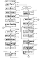
図2は、主基板31における回路構成の一例を示すブロック図である。なお、図2には、遊技機に搭載されている払出制御基板37、インタフェース基板66、中継基板77および演出制御基板80も示されている。主基板31には、プログラムに従ってパチンコ遊技機1を制御する基本回路(遊技制御手段に相当)53と、ゲートスイッチ32a、始動口スイッチ14a、カウントスイッチ23、および入賞口スイッチ29a,30a,33a,39aからの信号を基本回路53に与える入力ドライバ回路58と、可変入賞球装置15を開閉するソレノイド16、特別可変入賞球装置20を開閉するソレノイド21および大入賞口内の経路を切り換えるためのソレノイド21Aを基本回路53からの指令に従って駆動する出力回路59とが搭載されている。   FIG. 2 is a block diagram illustrating an example of a circuit configuration in the main board 31. 2 also shows a payout control board 37, an interface board 66, a relay board 77, and an effect control board 80 that are mounted on the gaming machine. The main board 31 includes a basic circuit (corresponding to a game control means) 53 for controlling the pachinko gaming machine 1 according to a program, a gate switch 32a, a start port switch 14a, a count switch 23, and winning port switches 29a, 30a, 33a, An input driver circuit 58 that gives a signal from 39a to the basic circuit 53, a solenoid 16 that opens and closes the variable winning ball apparatus 15, a solenoid 21 that opens and closes the special variable winning ball apparatus 20, and a solenoid 21A for switching the path in the big prize opening Is mounted in accordance with a command from the basic circuit 53.

なお、ゲートスイッチ32a、始動口スイッチ14a、カウントスイッチ23、入賞口スイッチ29a,30a,33a,39a等のスイッチは、センサと称されているものでもよい。すなわち、遊技球を検出できる遊技媒体検出手段(この例では遊技球検出手段)であれば、その名称を問わない。入賞検出を行う始動口スイッチ14a、カウントスイッチ23、および入賞口スイッチ29a,30a,33a,39aの各スイッチは、入賞領域への遊技球の入賞を検出する入賞検出手段でもある。なお、ゲート32のような通過ゲートであっても、賞球の払い出しが行われるものであれば、通過ゲートへ遊技球が進入することが入賞になり、通過ゲートに設けられているスイッチ(例えばゲートスイッチ32a)が入賞検出手段になる。   Note that the switches such as the gate switch 32a, the start port switch 14a, the count switch 23, and the winning port switches 29a, 30a, 33a, and 39a may be referred to as sensors. That is, the name of the game medium detection means is not limited as long as it is a game medium detection means (game ball detection means in this example) that can detect a game ball. Each of the start port switch 14a, the count switch 23, and the winning port switches 29a, 30a, 33a, and 39a that perform winning detection is also a winning detection means that detects the winning of a game ball in the winning area. Note that even if a passing gate such as the gate 32 is used, if a prize ball is paid out, a game ball entering the passing gate becomes a winning and a switch provided on the passing gate (for example, The gate switch 32a) becomes a winning detection means.

基本回路53は、ゲーム制御(遊技進行制御)用のプログラム等を記憶するROM54、ワークメモリとして使用される記憶手段(変動データを記憶する変動データ記憶手段)としてのRAM55、およびプログラムに従って制御動作を行うCPU56を有する遊技制御用マイクロコンピュータ560を含む。なお、この実施の形態では、CPU56とは、基本回路53のうち、プログラムに従って動作する中央処理装置(ROM54やRAM55などの記憶手段、I/Oポート部57などを除いた部分)を指し、後述するメイン処理や割込処理(タイマ割込処理)を実行する。また、遊技制御用マイクロコンピュータ560とは、基本回路53のうち、CPU56に加えて、ROM54やRAM55などの記憶手段、I/Oポート部57などを含む部分を指し、各基板(払出制御基板37や演出制御基板80)が搭載するマイクロコンピュータと各種データの送受信を行う。   The basic circuit 53 includes a ROM 54 for storing a program for game control (game progress control), a RAM 55 as storage means (variation data storage means for storing fluctuation data) used as a work memory, and a control operation according to the program. A game control microcomputer 560 having a CPU 56 is included. In this embodiment, the CPU 56 refers to a central processing unit (a portion excluding storage means such as the ROM 54 and RAM 55, the I / O port unit 57, etc.) of the basic circuit 53 that operates according to a program. Main processing and interrupt processing (timer interrupt processing) to be executed. The game control microcomputer 560 refers to a part of the basic circuit 53 including the CPU 56, storage means such as the ROM 54 and RAM 55, the I / O port 57, and the like. And transmission / reception of various data to / from the microcomputer mounted on the production control board 80).

この実施の形態では、ROM54、ワークメモリとしての記憶手段であるRAM55およびI/Oポート部57は遊技制御用マイクロコンピュータ560に内蔵されている。すなわち、遊技制御用マイクロコンピュータ560は、1チップマイクロコンピュータである。1チップマイクロコンピュータは、少なくともRAM55が内蔵されていればよく、ROM54は外付けであっても内蔵されていてもよい。   In this embodiment, the ROM 54, the RAM 55 serving as storage means as a work memory, and the I / O port unit 57 are built in the game control microcomputer 560. That is, the game control microcomputer 560 is a one-chip microcomputer. The one-chip microcomputer only needs to include at least the RAM 55, and the ROM 54 may be external or internal.

なお、遊技制御用マイクロコンピュータ560においてCPU56がROM54に格納されているプログラムに従って制御を実行するので、以下、遊技制御用マイクロコンピュータ560が実行する(または、処理を行う)ということは、具体的には、CPU56がプログラムに従って制御を実行することである。このことは、主基板31以外の他の基板に搭載されているマイクロコンピュータについても同様である。また、遊技制御手段は、遊技制御用マイクロコンピュータ560を含む基本回路53で実現されている。   In the game control microcomputer 560, the CPU 56 executes control in accordance with the program stored in the ROM 54. Therefore, hereinafter, the game control microcomputer 560 executes (or performs processing) specifically. Is that the CPU 56 executes control according to the program. The same applies to microcomputers mounted on substrates other than the main substrate 31. The game control means is realized by a basic circuit 53 including a game control microcomputer 560.

また、RAM55は、その一部または全部が電源基板910において作成されるバックアップ電源によってバックアップされている不揮発性記憶手段としてのバックアップRAMである。すなわち、遊技機に対する電力供給が停止しても、所定期間(バックアップ電源としてのコンデンサが放電してバックアップ電源が電力供給不能になるまで)は、RAM55の一部または全部の内容は保存される。特に、少なくとも、遊技状態すなわち遊技制御手段の制御状態に応じたデータ(特別図柄プロセスフラグ等)と未払出賞球数を示すデータは、バックアップRAMに保存される。遊技制御手段の制御状態に応じたデータとは、停電等が生じた後に復旧した場合に、そのデータにもとづいて、制御状態を停電等の発生前に復旧させるために必要なデータである。また、制御状態に応じたデータと未払出賞球数を示すデータとを遊技の進行状態を示すデータと定義する。なお、この実施の形態では、RAM55の全部が、電源バックアップされているとする。   The RAM 55 is a backup RAM as a non-volatile storage means, part or all of which is backed up by a backup power source created on the power supply substrate 910. That is, even if the power supply to the gaming machine is stopped, a part or all of the contents of the RAM 55 is stored for a predetermined period (until the capacitor as the backup power supply is discharged and the backup power supply cannot be supplied). In particular, at least data (special symbol process flag, etc.) corresponding to the game state, that is, the control state of the game control means, and data indicating the number of unpaid winning balls are stored in the backup RAM. The data corresponding to the control state of the game control means is data necessary for restoring the control state before the occurrence of a power failure or the like based on the data when the power is restored after a power failure or the like occurs. Further, data corresponding to the control state and data indicating the number of unpaid winning balls are defined as data indicating the progress state of the game. In this embodiment, it is assumed that the entire RAM 55 is backed up.

なお、遊技機1は、バックアップ電源電圧を検知し、検知した電圧値が所定時間継続して一定値以下に低下すると、電力が低下した旨を可変表示装置9に表示したり音やランプを用いて報知する報知手段を設けてもよい。なお、バックアップ電源はコンデンサに限らず、例えば、電池でもよく、コンデンサと電池とを併用して用いてもよい。要は、バックアップ電源は、工場から出荷して遊技店に遊技機を導入するまでの間、電力供給が可能なものであればよい。   Note that the gaming machine 1 detects the backup power supply voltage, and when the detected voltage value continues to decrease for a predetermined time and falls below a certain value, the game machine 1 displays on the variable display device 9 that the power has decreased or uses a sound or a lamp. Informing means for informing may be provided. Note that the backup power supply is not limited to a capacitor, and may be, for example, a battery or a combination of a capacitor and a battery. In short, the backup power source may be any power source that can supply power until it is shipped from the factory and the gaming machine is installed in the game store.

遊技制御用マイクロコンピュータ560のリセット端子には、電源基板910からのリセット信号が入力される。また、払出制御用マイクロコンピュータのリセット端子にも、電源基板910からのリセット信号が入力される。なお、リセット信号がハイレベルになると遊技制御用マイクロコンピュータ560および払出制御用マイクロコンピュータは動作可能状態になり、リセット信号がローレベルになると遊技制御用マイクロコンピュータ560および払出制御用マイクロコンピュータは動作停止状態になる。従って、リセット信号がハイレベルである期間は、遊技制御用マイクロコンピュータ560および払出制御用マイクロコンピュータの動作を許容する許容信号が出力されていることになり、リセット信号がローレベルである期間は、遊技制御用マイクロコンピュータ560および払出制御用マイクロコンピュータの動作を停止させる動作停止信号が出力されていることになる。なお、リセット回路をそれぞれの制御基板(主基板31を含む)に搭載してもよいし、複数の制御基板のうちの一つまたは複数にリセット回路を搭載し、そこからリセット信号を他の制御基板に供給するようにしてもよい。   A reset signal from the power supply board 910 is input to the reset terminal of the game control microcomputer 560. The reset signal from the power supply board 910 is also input to the reset terminal of the payout control microcomputer. When the reset signal becomes high level, the game control microcomputer 560 and the payout control microcomputer become operable, and when the reset signal becomes low level, the game control microcomputer 560 and the payout control microcomputer stop operating. It becomes a state. Accordingly, during the period in which the reset signal is at a high level, an allowable signal that allows the operation of the game control microcomputer 560 and the payout control microcomputer is output, and in the period in which the reset signal is at a low level, An operation stop signal for stopping the operations of the game control microcomputer 560 and the payout control microcomputer is output. A reset circuit may be mounted on each control board (including the main board 31), or a reset circuit is mounted on one or more of the plurality of control boards, and a reset signal is sent from there to another control circuit. You may make it supply to a board | substrate.

さらに、基本回路53の入力ポートには、払出制御基板37を経由して、電源基板910からの電源電圧が所定値以下に低下したことを示す電源断信号が入力される。また、基本回路53の入力ポートには、RAMの内容をクリアすることを指示するためのクリアスイッチが操作されたことを示すクリア信号が入力される。   Furthermore, a power-off signal indicating that the power supply voltage from the power supply board 910 has decreased to a predetermined value or less is input to the input port of the basic circuit 53 via the payout control board 37. A clear signal indicating that the clear switch for instructing to clear the contents of the RAM is operated is input to the input port of the basic circuit 53.

クリア信号は、主基板31において分岐され、払出制御基板37にも供給される。なお、遊技制御用マイクロコンピュータ560が入力ポートを介して入力したクリア信号の状態を、出力ポートを介して払出制御基板37に出力してもよい。   The clear signal is branched in the main board 31 and is also supplied to the payout control board 37. Note that the state of the clear signal input by the game control microcomputer 560 via the input port may be output to the payout control board 37 via the output port.

この実施の形態では、演出制御基板80などに搭載されている演出制御手段(演出制御用マイクロコンピュータや各種処理回路で構成される。)が、中継基板77を介して遊技制御用マイクロコンピュータ560からの演出制御コマンドを受信し、飾り図柄を可変表示する可変表示装置9の表示制御を行う。また、演出制御手段は、音声出力基板70を介してスピーカ(音出力装置)27の音出力制御を行ったり、ランプドライバ基板35を介して各ランプ25,28a,28b,28cの表示制御等を行う。また、この実施の形態では、「演出制御」とは、可変表示装置9の表示制御や、スピーカ27の音出力制御、各ランプ25,28a,28b,28cの表示制御を行うことによって、遊技演出などの演出を行うことをいう。また、この実施の形態では、演出制御手段は、可変表示装置9の表示制御、スピーカ27の音出力制御、および各ランプ25,28a,28b,28cの表示制御を行う演出制御用マイクロコンピュータ100や各種処理回路(例えば、後述するリアルタイムクロック353やバックアップ電源回路355、音声合成用IC703)によって実現される。   In this embodiment, effect control means (configured by an effect control microcomputer and various processing circuits) mounted on the effect control board 80 and the like is provided from the game control microcomputer 560 via the relay board 77. The display control of the variable display device 9 that variably displays the decorative design is performed. Further, the effect control means performs sound output control of the speaker (sound output device) 27 via the audio output board 70, or performs display control of each lamp 25, 28a, 28b, 28c via the lamp driver board 35. Do. In this embodiment, “effect control” means display control of the variable display device 9, sound output control of the speaker 27, and display control of the lamps 25, 28a, 28b, and 28c. It means performing such as. In this embodiment, the effect control means includes an effect control microcomputer 100 that performs display control of the variable display device 9, sound output control of the speaker 27, and display control of the lamps 25, 28a, 28b, and 28c. This is realized by various processing circuits (for example, a real-time clock 353, a backup power supply circuit 355, and a speech synthesis IC 703 described later).

図3は、中継基板77および演出制御基板80の回路構成例を示すブロック図である。図3に示すように、この実施の形態では、遊技機1は、可変表示装置9の表示制御を行うための演出制御基板80と、音出力装置27の音出力制御を行うための音声出力基板70と、各ランプ25,28a,28b,28cの表示制御を行うためのランプドライバ基板35とを含む。なお、この実施の形態では、複数の制御基板(演出制御基板80,音声出力基板70、ランプドライバ基板35)を用いて、可変表示装置9の表示制御や、音出力装置27の音出力制御、各ランプ25,28a,28b,28cの表示制御を行う場合を説明するが、1つの制御基板(例えば、1つの演出制御基板)を用いて行ってもよい。   FIG. 3 is a block diagram illustrating a circuit configuration example of the relay board 77 and the effect control board 80. As shown in FIG. 3, in this embodiment, the gaming machine 1 includes an effect control board 80 for performing display control of the variable display device 9 and a sound output board for performing sound output control of the sound output device 27. 70 and a lamp driver board 35 for performing display control of each of the lamps 25, 28a, 28b, 28c. In this embodiment, display control of the variable display device 9 and sound output control of the sound output device 27 are performed using a plurality of control boards (production control board 80, audio output board 70, lamp driver board 35). Although the case where display control of each lamp 25, 28a, 28b, 28c is performed will be described, it may be performed using one control board (for example, one effect control board).

演出制御基板80は、演出制御用CPU101、ROM84、RAM85およびI/Oポート87を含む演出制御用マイクロコンピュータ100を搭載している。なお、RAM85は外付けであってもよい。演出制御基板80において、演出制御用マイクロコンピュータ100は、内蔵または外付けのROM84に格納されたプログラムに従って動作し、中継基板77を介して入力される主基板31からのストローブ信号(演出制御INT信号)に応じて、入力ドライバ102および入力ポート103を介して演出制御コマンドを受信する。また、演出制御用マイクロコンピュータ100は、演出制御コマンドにもとづいて、VDP(ビデオディスプレイプロセッサ)109に、LCDを用いた可変表示装置9の表示制御を行わせる。   The effect control board 80 includes an effect control microcomputer 100 including an effect control CPU 101, ROM 84, RAM 85, and I / O port 87. The RAM 85 may be externally attached. In the effect control board 80, the effect control microcomputer 100 operates in accordance with a program stored in a built-in or external ROM 84, and a strobe signal (effect control INT signal from the main board 31 input via the relay board 77. ), The presentation control command is received via the input driver 102 and the input port 103. Further, the effect control microcomputer 100 causes the VDP (video display processor) 109 to perform display control of the variable display device 9 using the LCD based on the effect control command.

演出制御コマンドおよび演出制御INT信号は、演出制御基板80において、まず、入力ドライバ102に入力する。入力ドライバ102は、中継基板77から入力された信号を演出制御基板80の内部に向かう方向にしか通過させない(演出制御基板80の内部から中継基板77への方向には信号を通過させない)信号方向規制手段としての単方向性回路でもある。   The effect control command and the effect control INT signal are first input to the input driver 102 on the effect control board 80. The input driver 102 passes the signal input from the relay board 77 only in the direction toward the inside of the effect control board 80 (does not pass the signal in the direction from the inside of the effect control board 80 to the relay board 77). It is also a unidirectional circuit as a regulating means.

中継基板77には、主基板31から入力された信号を演出制御基板80に向かう方向にしか通過させない(演出制御基板80から中継基板77への方向には信号を通過させない)信号方向規制手段としての単方向性回路が搭載されている。単方向性回路として、例えばダイオードやトランジスタが使用される。図3には、ダイオードが例示されている。また、単方向性回路は、各信号毎に設けられる。   As a signal direction regulating means, the signal inputted from the main board 31 is allowed to pass through the relay board 77 only in the direction toward the effect control board 80 (the signal is not passed in the direction from the effect control board 80 to the relay board 77). The unidirectional circuit is installed. For example, a diode or a transistor is used as the unidirectional circuit. FIG. 3 illustrates a diode. A unidirectional circuit is provided for each signal.

さらに、演出制御用マイクロコンピュータ100は、ランプドライバ基板35に搭載されたランプドライバ352に対してランプを駆動する信号を出力する。ランプドライバ352は、ランプを駆動する信号を増幅して装飾ランプ25や天枠ランプ28a、左枠ランプ28b、右枠ランプ28c、球切れランプ51、賞球ランプ52などの各ランプに供給する。   Further, the effect control microcomputer 100 outputs a signal for driving the lamp to the lamp driver 352 mounted on the lamp driver board 35. The lamp driver 352 amplifies a signal for driving the lamp and supplies the amplified lamp 25 to the lamps such as the decoration lamp 25, the top frame lamp 28a, the left frame lamp 28b, the right frame lamp 28c, the ball-out lamp 51, and the prize ball lamp 52.

また、演出制御用マイクロコンピュータ100は、音声出力基板70に搭載された音声合成用IC173に対して音番号データを出力する。音声合成用IC173は、音番号データに応じた音声や効果音を発生し増幅回路175に出力する。増幅回路175は、音声合成用IC173の出力レベルを、ボリューム176で設定されている音量に応じたレベルに増幅した音声信号をスピーカ27に出力する。音声データROM174には、音番号データに応じた制御データが格納されている。音番号データに応じた制御データは、所定期間(例えば飾り図柄の変動期間)における効果音または音声の出力態様を時系列的に示すデータの集まりである。   The production control microcomputer 100 outputs sound number data to the speech synthesis IC 173 mounted on the speech output board 70. The voice synthesizing IC 173 generates a voice or a sound effect corresponding to the sound number data and outputs it to the amplifier circuit 175. The amplifier circuit 175 outputs an audio signal obtained by amplifying the output level of the speech synthesis IC 173 to a level corresponding to the volume set by the volume 176 to the speaker 27. The voice data ROM 174 stores control data corresponding to the sound number data. The control data corresponding to the sound number data is a collection of data indicating the sound effect or sound output mode in a time series in a predetermined period (for example, a decorative symbol variation period).

なお、ランプを駆動する信号および音番号データは、演出制御用マイクロコンピュータ100とランプドライバ352および音声合成IC173との間で、双方向通信(信号受信側から送信側に応答信号を送信するような通信)によって伝達される。   The signal for driving the lamp and the sound number data are communicated between the production control microcomputer 100, the lamp driver 352, and the speech synthesis IC 173 (such as transmitting a response signal from the signal receiving side to the transmitting side). Communication).

演出制御用マイクロコンピュータ100は、受信した演出制御コマンドに従ってキャラクタROM89から必要なデータを読み出す。キャラクタROM89は、可変表示装置9に表示される画像の中でも使用頻度の高いキャラクタ画像データ、具体的には、人物、文字、図形または記号等(飾り図柄を含む)をあらかじめ格納しておくためのものである。演出制御用マイクロコンピュータ100は、キャラクタROM89から読み出したデータをVDP109に出力する。VDP109は、演出制御用マイクロコンピュータ100から入力されたデータにもとづいて可変表示装置9の表示制御を実行する。   The effect control microcomputer 100 reads necessary data from the character ROM 89 in accordance with the received effect control command. The character ROM 89 stores character image data frequently used among images displayed on the variable display device 9, specifically, a person, a character, a figure, a symbol, or the like (including decorative designs) in advance. Is. The effect control microcomputer 100 outputs the data read from the character ROM 89 to the VDP 109. The VDP 109 executes display control of the variable display device 9 based on data input from the production control microcomputer 100.

この実施の形態では、可変表示装置9の表示制御を行うVDP109が演出制御基板80に搭載されている。VDP109は、演出制御用マイクロコンピュータ100とは独立したアドレス空間を有し、そこにVRAM83をマッピングする。VRAM83は、VDP109によって生成された画像データを展開するためのバッファメモリである。そして、VDP109は、VRAM83内の画像データを可変表示装置9に出力する。   In this embodiment, a VDP 109 that performs display control of the variable display device 9 is mounted on the effect control board 80. The VDP 109 has an address space independent of the production control microcomputer 100 and maps the VRAM 83 therein. The VRAM 83 is a buffer memory for expanding image data generated by the VDP 109. Then, the VDP 109 outputs the image data in the VRAM 83 to the variable display device 9.

また、この実施の形態では、ランプドライバ基板35には、現在時刻を出力するリアルタイムクロック(RTC)353が搭載されている。演出制御用マイクロコンピュータ100は、リアルタイムクロック353から現在の日付(年、月、日、曜日)を示す日付信号や現在の時刻(時、分、秒)を示す時刻信号を入力し、現在の日時にもとづいて各種処理を実行する。リアルタイムクロック353は、通常、遊技機に電源が供給されているときには遊技機からの電源によって動作し、遊技機の電源が切られているときには、ランプドライバ35に搭載されたバックアップ電源回路355(例えば、バッテリ)から供給される電源によって動作する。従って、リアルタイムクロック353は、遊技機の電源が切られている場合であっても現在の日時を計時することができる。なお、リアルタイムクロック353は、遊技機に電源が供給されているときであったもバックアップ電源回路355から供給される電源によって動作するようにしてもよい。   In this embodiment, the lamp driver board 35 is mounted with a real-time clock (RTC) 353 that outputs the current time. The production control microcomputer 100 inputs a date signal indicating the current date (year, month, day, day of the week) and a time signal indicating the current time (hour, minute, second) from the real-time clock 353, and the current date and time. Various processes are executed based on the above. The real-time clock 353 is normally operated by power from the gaming machine when power is supplied to the gaming machine, and a backup power supply circuit 355 (for example, mounted on the lamp driver 35 when the gaming machine is powered off). The battery is operated by the power supplied from the battery. Therefore, the real-time clock 353 can measure the current date and time even when the gaming machine is turned off. Note that the real time clock 353 may be operated by the power supplied from the backup power supply circuit 355 even when power is supplied to the gaming machine.

また、バックアップ電源回路355の電源は、ランプドライバ基板35に搭載されているバックアップRAM356にも供給される。すなわち、バックアップRAM356は、通常、遊技機に電源が供給されているときには遊技機からの電源が供給され、遊技機の電源が切られているときには、ランプドライバ35に搭載されたバックアップ電源回路355から電源が供給される。なお、バックアップRAM356は、遊技機に電源が供給されているときであったもバックアップ電源回路355から電源が供給されてもよい。   The power of the backup power supply circuit 355 is also supplied to the backup RAM 356 mounted on the lamp driver board 35. That is, the backup RAM 356 is normally supplied with power from the gaming machine when power is supplied to the gaming machine, and from the backup power supply circuit 355 mounted on the lamp driver 35 when the gaming machine is turned off. Power is supplied. Note that the backup RAM 356 may be supplied with power from the backup power supply circuit 355 even when power is supplied to the gaming machine.

なお、リアルタイムクロック353をランプドライバ基板35ではなく、演出制御基板80や音声出力基板70に搭載してもよい。また、リアルタイムクロック353を主基板31に搭載するようにしてもよい。また、リアルタイムクロック353を設けずに、バックアップRAM356に設けたカウンタをカウントアップする(例えば、遊技機の電源をオンしてからの始動入賞回数をカウントアップする)ことによって計時してもよい。そして、演出制御用マイクロコンピュータ100は、バックアップRAM356に設けたカウンタのカウント値にもとづいて各種処理を実行してもよい。   Note that the real-time clock 353 may be mounted on the effect control board 80 or the audio output board 70 instead of the lamp driver board 35. Further, the real time clock 353 may be mounted on the main board 31. Alternatively, the real time clock 353 may not be provided, and the time may be measured by counting up a counter provided in the backup RAM 356 (for example, counting up the number of winning winnings after the game machine is turned on). Then, the effect control microcomputer 100 may execute various processes based on the count value of the counter provided in the backup RAM 356.

また、この実施の形態では、演出制御用マイクロコンピュータ100は、操作ボタン120からの操作信号にもとづいて遊技演出を行う。また、演出制御用マイクロコンピュータ100は、操作ボタン120からの操作信号にもとづいて各種設定処理を行う。この実施の形態では、演出制御用マイクロコンピュータ100は、後述するように、操作ボタン120からの操作信号にもとづいて告知演出で遊技者に告知する告知内容を設定する。なお、操作ボタン120からの操作信号にもとづいて告知内容を設定するのではなく、ランプドライバ基板35に設けられた設定スイッチ354からのオン/オフ信号にもとづいて告知内容を設定してもよい。また、設定スイッチ354を演出制御基板80または音声出力基板70に設けてもよい。また、設定スイッチ354は、ディップスイッチやプッシュロックスイッチ、ロータリスイッチのようにスイッチ側でオン/オフを固定できるものであってもよい。   In this embodiment, the effect control microcomputer 100 performs a game effect based on an operation signal from the operation button 120. Further, the production control microcomputer 100 performs various setting processes based on operation signals from the operation buttons 120. In this embodiment, the production control microcomputer 100 sets the notification content to be notified to the player in the notification production based on the operation signal from the operation button 120, as will be described later. Instead of setting the notification content based on the operation signal from the operation button 120, the notification content may be set based on an on / off signal from a setting switch 354 provided on the lamp driver board 35. Further, the setting switch 354 may be provided on the effect control board 80 or the audio output board 70. The setting switch 354 may be a switch that can be turned on / off on the switch side, such as a dip switch, a push lock switch, or a rotary switch.

次に、リアルタイムクロック353の構成について説明する。図4は、リアルタイムクロック353の構成例を示すブロック図である。リアルタイムクロック353は、例えば、水晶発振子を内蔵したシリアルインタフェース方式のリアルタイムクロックモジュールとして実現される。図4に示すように、リアルタイムクロック353は、水晶発振子360、出力制御部361、割込制御部362、バス/インタフェース回路363、クロック出力/カレンダ機能部364、タイマレジスタ365、アラームレジスタ366、コントロールレジスタ367およびシフトレジスタ368を含む。   Next, the configuration of the real time clock 353 will be described. FIG. 4 is a block diagram illustrating a configuration example of the real time clock 353. The real time clock 353 is realized, for example, as a serial interface type real time clock module having a built-in crystal oscillator. As shown in FIG. 4, the real-time clock 353 includes a crystal oscillator 360, an output control unit 361, an interrupt control unit 362, a bus / interface circuit 363, a clock output / calendar function unit 364, a timer register 365, an alarm register 366, A control register 367 and a shift register 368 are included.

水晶発振子360は、所定の発振周波数(例えば、32.768kHz)の発振信号を出力する。クロック出力/カレンダ機能部364は、水晶発振子360からの発振信号にもとづいてクロック信号を出力する機能を備える。また、クロック出力/カレンダ機能部364は、水晶発振子360からの発振信号にもとづいて日時や時刻を計時する機能を備える。例えば、クロック出力/カレンダ機能部364は、時計カウンタを備え、水晶発振子360からの発振信号にもとづいて時計カウンタをカウントアップすることによって時刻(時、分、秒)を計時する。また、例えば、クロック出力/カレンダ機能部364は、カレンダカウンタを備え、水晶発振子360からの発振信号にもとづいてカレンダカウンタをカウントアップすることによって日付(年、月、日)を管理する。また、例えば、クロック出力/カレンダ機能部364は、曜日カウンタを備え、水晶発振子360からの発振信号にもとづいて曜日カウンタをカウントアップすることによって曜日を管理する。   The crystal oscillator 360 outputs an oscillation signal having a predetermined oscillation frequency (for example, 32.768 kHz). The clock output / calendar function unit 364 has a function of outputting a clock signal based on the oscillation signal from the crystal oscillator 360. The clock output / calendar function unit 364 has a function of measuring the date and time based on the oscillation signal from the crystal oscillator 360. For example, the clock output / calendar function unit 364 includes a clock counter and counts time (hour, minute, second) by counting up the clock counter based on the oscillation signal from the crystal oscillator 360. For example, the clock output / calendar function unit 364 includes a calendar counter, and manages the date (year, month, day) by counting up the calendar counter based on the oscillation signal from the crystal oscillator 360. Further, for example, the clock output / calendar function unit 364 includes a day of the week counter, and manages the day of the week by counting up the day of the week counter based on the oscillation signal from the crystal oscillator 360.

シフトレジスタ368は、クロック出力/カレンダ機能部364が計時する日付や時刻をシリアルデータに変換してバス/インタフェース回路363に出力する機能を備える。バス/インタフェース回路363は、シフトレジスタ368からの入力にもとづいて、現在の日付信号や時刻信号(DATA)をシリアルデータとして出力する機能を備える。また、バス/インタフェース回路363は、クロック出力/カレンダ機能部364の出力にもとづいてクロック信号(CLK)を出力する機能を備える。   The shift register 368 has a function of converting the date and time counted by the clock output / calendar function unit 364 into serial data and outputting the serial data to the bus / interface circuit 363. The bus / interface circuit 363 has a function of outputting the current date signal and time signal (DATA) as serial data based on the input from the shift register 368. The bus / interface circuit 363 has a function of outputting a clock signal (CLK) based on the output of the clock output / calendar function unit 364.

出力制御部361は、水晶発振子360からの発振信号にもとづいて、あらかじめ設定された周波数のクロック信号(FOUT)を出力する機能を備える。例えば、出力制御部361は、周波数設定レジスタを備え、外部入力(FCON)にもとづいて周波数設定レジスタにあらかじめ周波数を設定する。そして、周波数設定レジスタに設定された設定周波数にもとづいてクロック信号(FOUT)を出力する。   The output control unit 361 has a function of outputting a clock signal (FOUT) having a preset frequency based on the oscillation signal from the crystal oscillator 360. For example, the output control unit 361 includes a frequency setting register, and presets the frequency in the frequency setting register based on an external input (FCON). Then, a clock signal (FOUT) is output based on the set frequency set in the frequency setting register.

割込制御部362は、タイマレジスタ365に設定された設定値(定周期割込時刻)にもとづいて、所定周期ごとに割込信号(TIRQ)を出力する機能を備える。また、割込制御部362は、アラームレジスタ366に設定された設定値(アラーム時刻)にもとづいて、所定の時刻にアラームとしての割込信号(AIRQ)を出力する機能を備える。   The interrupt control unit 362 has a function of outputting an interrupt signal (TIRQ) at predetermined intervals based on a set value (fixed period interrupt time) set in the timer register 365. The interrupt control unit 362 has a function of outputting an interrupt signal (AIRQ) as an alarm at a predetermined time based on a set value (alarm time) set in the alarm register 366.

また、この実施の形態では、リアルタイムクロック353は、2つのイネーブル信号(CE0,CE1)の入力がともにハイレベルとなったときに、外部からのアクセスが可能となる。例えば、リアルタイムクロック353の各レジスタの設定値をセットしたり、リアルタイムクロック353が計時する時刻を外部から調整したりする場合には、2つのイネーブル信号(CE0,CE1)の入力がともにハイレベルとされアクセス許可状態とされて、外部からコマンドが入力される。   In this embodiment, the real-time clock 353 can be accessed from the outside when the inputs of the two enable signals (CE0, CE1) both become high level. For example, when setting values of the registers of the real-time clock 353 or adjusting the time measured by the real-time clock 353 from the outside, the inputs of the two enable signals (CE0, CE1) are both set to the high level. Then, the access is permitted and a command is input from the outside.

次に遊技機の動作について説明する。図5および図6は、遊技機に対して電力供給が開始され遊技制御用マイクロコンピュータ560へのリセット信号がハイレベルになったことに応じて遊技制御用マイクロコンピュータ560のCPU56が実行するメイン処理を示すフローチャートである。リセット信号が入力されるリセット端子の入力レベルがハイレベルになると、遊技制御用マイクロコンピュータ560のCPU56は、プログラムの内容が正当か否かを確認するための処理であるセキュリティチェック処理を実行した後、ステップS1以降のメイン処理を開始する。メイン処理において、CPU56は、まず、必要な初期設定を行う。   Next, the operation of the gaming machine will be described. 5 and 6 show main processing executed by the CPU 56 of the game control microcomputer 560 in response to the start of power supply to the game machine and the reset signal to the game control microcomputer 560 becoming high level. It is a flowchart which shows. When the input level of the reset terminal to which the reset signal is input becomes a high level, the CPU 56 of the game control microcomputer 560 executes a security check process that is a process for confirming whether the contents of the program are valid. The main processing after step S1 is started. In the main process, the CPU 56 first performs necessary initial settings.

初期設定処理において、CPU56は、まず、割込禁止に設定する(ステップS1)。次に、マスク可能割込の割込モードを設定し(ステップS2)、スタックポインタにスタックポインタ指定アドレスを設定する(ステップS3)。なお、ステップS2では、遊技制御用マイクロコンピュータ560の特定レジスタ(Iレジスタ)の値(1バイト)と内蔵デバイスが出力する割込ベクタ(1バイト:最下位ビット0)から合成されるアドレスが、割込番地を示すモードに設定する。また、マスク可能な割込が発生すると、CPU56は、自動的に割込禁止状態に設定するとともに、プログラムカウンタの内容をスタックにセーブする。   In the initial setting process, the CPU 56 first sets the interrupt prohibition (step S1). Next, an interrupt mode for maskable interrupts is set (step S2), and a stack pointer designation address is set for the stack pointer (step S3). In step S2, the address synthesized from the value (1 byte) of the specific register (I register) of the game control microcomputer 560 and the interrupt vector (1 byte: least significant bit 0) output from the built-in device is Set to the mode indicating the interrupt address. When a maskable interrupt occurs, the CPU 56 automatically sets the interrupt disabled state and saves the contents of the program counter in the stack.

次いで、内蔵デバイスレジスタの設定(初期化)を行う(ステップS4)。ステップS4の処理によって、内蔵デバイス(内蔵周辺回路)であるCTC(カウンタ/タイマ)およびPIO(パラレル入出力ポート)の設定(初期化)がなされる。   Next, the built-in device register is set (initialized) (step S4). By the processing in step S4, the CTC (counter / timer) and PIO (parallel input / output port) which are built-in devices (built-in peripheral circuits) are set (initialized).

この実施の形態で用いられる遊技制御用マイクロコンピュータ560は、I/Oポート(PIO)およびタイマ/カウンタ回路(CTC)504も内蔵している。   The game control microcomputer 560 used in this embodiment also incorporates an I / O port (PIO) and a timer / counter circuit (CTC) 504.

次に、入力ポート1のビット0の状態によって電源断信号がオフ状態になっているか否か確認する(ステップS5)。遊技機に対する電力供給が開始されたときに、+5V電源などの各種電源の出力電圧は徐々に規定値に達するのであるが、ステップS5の処理によって、すなわち、電源断信号が出力されていない(ハイレベルになっている)ことを確認することによりCPU56は電源電圧が安定したことを確認することができる。   Next, it is confirmed whether or not the power-off signal is in an OFF state depending on the state of bit 0 of the input port 1 (step S5). When the power supply to the gaming machine is started, the output voltage of various power sources such as the + 5V power source gradually reaches the specified value, but the power-off signal is not output by the process of step S5, that is, the high power By confirming that the power supply voltage is stable, the CPU 56 can confirm that the power supply voltage is stable.

電源断信号がオン状態である場合には、CPU56は、所定期間(例えば、0.1秒)の遅延時間の後に(ステップS80)、再度、電源断信号がオフ状態になっているか否か確認する。電源断信号がオフ状態になっている場合には、RAM55をアクセス可能状態に設定し(ステップS6)、クリア信号のチェック処理に移行する。   When the power-off signal is in the on state, the CPU 56 confirms again whether the power-off signal is in the off state after a delay time of a predetermined period (for example, 0.1 second) (step S80). To do. If the power-off signal is off, the RAM 55 is set to an accessible state (step S6), and the process proceeds to a clear signal check process.

なお、電源断信号がオフ状態である場合に、遊技の進行を制御する遊技装置制御処理(遊技制御処理)の開始タイミングをソフトウェアで遅らせるためのソフトウェア遅延処理を実行するようにしてもよい。そのようなソフトウェア遅延処理によって、ソフトウェア遅延処理を実行しない場合に比べて、遊技制御処理の開始タイミングを遅延させることができる。遅延処理を実行したときには、他の制御基板(例えば、払出制御基板37)に対して、遊技制御基板(主基板31)が送信するコマンドを他の制御基板のマイクロコンピュータが受信できないという状況が発生することを防止できる。   When the power-off signal is in the off state, software delay processing for delaying the start timing of the gaming device control processing (game control processing) for controlling the progress of the game by software may be executed. By such software delay processing, the start timing of the game control processing can be delayed as compared with the case where the software delay processing is not executed. When the delay process is executed, a situation occurs in which the microcomputer of the other control board cannot receive the command transmitted from the game control board (main board 31) to the other control board (for example, the payout control board 37). Can be prevented.

次いで、CPU56は、クリアスイッチがオンされているか否か確認する(ステップS7)。なお、CPU56は、入力ポート0を介して1回だけクリア信号の状態を確認するようにしてもよいが、複数回クリア信号の状態を確認するようにしてもよい。例えば、クリア信号の状態がオフ状態であることを確認したら、所定時間(例えば、0.1秒)の遅延時間をおいた後、クリア信号の状態を再確認する。そのときにクリア信号の状態がオン状態であることを確認したら、クリア信号がオン状態になっていると判定する。また、このときにクリア信号の状態がオフ状態であることを確認したら、所定時間の遅延時間をおいた後、再度、クリア信号の状態を再確認するようにしてもよい。ここで、再確認の回数は、1回または2回に限られず、3回以上であってもよい。また、2回チェックして、チェック結果が一致していなかったときにもう一度確認するようにしてもよい。   Next, the CPU 56 checks whether or not the clear switch is turned on (step S7). Note that the CPU 56 may confirm the state of the clear signal only once via the input port 0, but may confirm the state of the clear signal a plurality of times. For example, if it is confirmed that the state of the clear signal is an off state, after a delay time of a predetermined time (for example, 0.1 seconds), the state of the clear signal is reconfirmed. If it is confirmed that the clear signal is in the on state at that time, it is determined that the clear signal is in the on state. Further, at this time, if it is confirmed that the state of the clear signal is the off state, after a delay time of a predetermined time, the state of the clear signal may be confirmed again. Here, the number of reconfirmations is not limited to once or twice, but may be three or more times. It is also possible to check twice and check again when the check results do not match.

ステップS7でクリアスイッチがオンでない場合には、遊技機への電力供給が停止したときにバックアップRAM領域のデータ保護処理(例えばパリティデータの付加等の電力供給停止時処理)が行われたか否か確認する(ステップS8)。この実施の形態では、電力供給の停止が生じた場合には、バックアップRAM領域のデータを保護するための処理が行われている。そのような電力供給停止時処理が行われていたことを確認した場合には、CPU56は、電力供給停止時処理が行われた、すなわち電力供給停止時の制御状態が保存されていると判定する。電力供給停止時処理が行われていないことを確認した場合には、CPU56は初期化処理を実行する。   If the clear switch is not turned on in step S7, whether or not data protection processing of the backup RAM area (for example, power supply stop processing such as addition of parity data) has been performed when power supply to the gaming machine is stopped Confirm (step S8). In this embodiment, when power supply is stopped, a process for protecting data in the backup RAM area is performed. When it is confirmed that such power supply stop processing has been performed, the CPU 56 determines that the power supply stop processing has been performed, that is, the control state at the time of power supply stop is stored. . When it is confirmed that the power supply stop process is not performed, the CPU 56 executes an initialization process.

電力供給停止時処理が行われていたか否かは、電力供給停止時処理においてバックアップRAM領域に保存されるバックアップ監視タイマの値が、電力供給停止時処理を実行したことに応じた値(例えば2)になっているか否かによって確認される。なお、そのような確認の仕方は一例であって、例えば、電力供給停止時処理においてバックアップフラグ領域に電力供給停止時処理を実行したことを示すフラグをセットし、ステップS8において、そのフラグがセットされていることを確認したら電力供給停止時処理が行われたと判定してもよい。   Whether or not the power supply stop process has been performed is determined by the value of the backup monitoring timer stored in the backup RAM area in the power supply stop process corresponding to the execution of the power supply stop process (for example, 2). ) Is confirmed by whether or not. Note that such a confirmation method is an example. For example, a flag indicating that the power supply stop process has been executed is set in the backup flag area in the power supply stop process, and the flag is set in step S8. If it is confirmed that the power supply is stopped, it may be determined that the power supply stop process has been performed.

電力供給停止時の制御状態が保存されていると判定したら、CPU56は、バックアップRAM領域のデータチェック(この例ではパリティチェック)を行う(ステップS9)。この実施の形態では、クリアデータ(00)をチェックサムデータエリアにセットし、チェックサム算出開始アドレスをポインタにセットする。また、チェックサムの対象になるデータ数に対応するチェックサム算出回数をセットする。そして、チェックサムデータエリアの内容とポインタが指すRAM領域の内容との排他的論理和を演算する。演算結果をチェックサムデータエリアにストアするとともに、ポインタの値を1増やし、チェックサム算出回数の値を1減算する。以上の処理が、チェックサム算出回数の値が0になるまで繰り返される。チェックサム算出回数の値が0になったら、CPU56は、チェックサムデータエリアの内容の各ビットの値を反転し、反転後のデータをチェックサムにする。   If it is determined that the control state at the time of stopping power supply is stored, the CPU 56 performs data check (parity check in this example) in the backup RAM area (step S9). In this embodiment, clear data (00) is set in the checksum data area, and the checksum calculation start address is set in the pointer. Also, the number of checksum calculations corresponding to the number of data to be checksum is set. Then, the exclusive OR of the contents of the checksum data area and the contents of the RAM area pointed to by the pointer is calculated. The calculation result is stored in the checksum data area, the pointer value is incremented by 1, and the checksum calculation count value is decremented by 1. The above processing is repeated until the value of the checksum calculation count becomes zero. When the value of the checksum calculation count becomes 0, the CPU 56 inverts the value of each bit of the contents of the checksum data area and uses the inverted data as the checksum.

電力供給停止時処理において、上記の処理と同様の処理によってチェックサムが算出され、チェックサムはバックアップRAM領域に保存されている。ステップS9では、算出したチェックサムと保存されているチェックサムとを比較する。不測の停電等の電力供給停止が生じた後に復旧した場合には、バックアップRAM領域のデータは保存されているはずであるから、チェック結果(比較結果)は正常(一致)になる。チェック結果が正常でないということは、バックアップRAM領域のデータが、電力供給停止時のデータとは異なっている可能性があることを意味する。そのような場合には、内部状態を電力供給停止時の状態に戻すことができないので、電力供給の停止からの復旧時でない電源投入時に実行される初期化処理(ステップS10〜S14の処理)を実行する。   In the power supply stop process, a checksum is calculated by the same process as described above, and the checksum is stored in the backup RAM area. In step S9, the calculated checksum is compared with the stored checksum. When the power supply is stopped after an unexpected power failure or the like, the data in the backup RAM area should be saved, so the check result (comparison result) is normal (matched). That the check result is not normal means that the data in the backup RAM area may be different from the data when the power supply is stopped. In such a case, since the internal state cannot be returned to the state when the power supply is stopped, the initialization process (the process of steps S10 to S14) executed when the power is turned on, not when the power supply is stopped is stopped. Run.

チェック結果が正常であれば、CPU56は、遊技制御手段の内部状態と演出制御手段等の電気部品制御手段の制御状態を電力供給停止時の状態に戻すための遊技状態復旧処理を行う。具体的には、ROM54に格納されているバックアップ時設定テーブルの先頭アドレスをポインタに設定し(ステップS91)、バックアップ時設定テーブルの内容を順次作業領域(RAM55内の領域)に設定する(ステップS92)。作業領域はバックアップ電源によって電源バックアップされている。バックアップ時設定テーブルには、作業領域のうち初期化してもよい領域についての初期化データが設定されている。ステップS91およびS92の処理によって、作業領域のうち初期化してはならない部分については、保存されていた内容がそのまま残る。初期化してはならない部分とは、例えば、電力供給停止前の遊技状態を示すデータ(特別図柄プロセスフラグなど)、出力ポートの出力状態が保存されている領域(出力ポートバッファ)、未払出賞球数を示すデータが設定されている部分などである。   If the check result is normal, the CPU 56 performs a game state restoration process for returning the internal state of the game control means and the control state of the electrical component control means such as the effect control means to the state when the power supply is stopped. Specifically, the start address of the backup setting table stored in the ROM 54 is set as a pointer (step S91), and the contents of the backup setting table are sequentially set in the work area (area in the RAM 55) (step S92). ). The work area is backed up by a backup power source. In the backup setting table, initialization data for an area that may be initialized in the work area is set. As a result of the processing in steps S91 and S92, the saved contents of the work area that should not be initialized remain. The parts that should not be initialized include, for example, data indicating the gaming state before the power supply is stopped (special symbol process flag, etc.), the area where the output state of the output port is saved (output port buffer), unpaid prize balls This is the part where data indicating the number is set.

また、CPU56は、ROM54に格納されているバックアップ時コマンド送信テーブルの先頭アドレスをポインタに設定し(ステップS93)、ステップS15に移行する。   Further, the CPU 56 sets the head address of the backup command transmission table stored in the ROM 54 as a pointer (step S93), and proceeds to step S15.

初期化処理では、CPU56は、まず、RAMクリア処理を行う(ステップS10)。なお、RAM55の全領域を初期化せず、所定のデータをそのままにしてもよい。また、ROM54に格納されている初期化時設定テーブルの先頭アドレスをポインタに設定し(ステップS11)、初期化時設定テーブルの内容を順次作業領域に設定する(ステップS12)。   In the initialization process, the CPU 56 first performs a RAM clear process (step S10). Note that the predetermined data may be left as it is without initializing the entire area of the RAM 55. Further, the start address of the initialization setting table stored in the ROM 54 is set as a pointer (step S11), and the contents of the initialization setting table are sequentially set in the work area (step S12).

ステップS11およびS12の処理によって、例えば、普通図柄判定用乱数カウンタ、普通図柄判定用バッファ、特別図柄バッファ、総賞球数格納バッファ、特別図柄プロセスフラグ、賞球中フラグ、球切れフラグなど制御状態に応じて選択的に処理を行うためのフラグに初期値が設定される。また、出力ポートバッファにおける接続確認信号を出力する出力ポートに対応するビットがセット(接続確認信号のオン状態に対応)される。   Control states such as a normal symbol determination random number counter, a normal symbol determination buffer, a special symbol buffer, a total prize ball number storage buffer, a special symbol process flag, an award ball flag, an out-of-ball flag, etc. An initial value is set in a flag for selectively performing processing according to the above. In addition, a bit corresponding to the output port that outputs the connection confirmation signal in the output port buffer is set (corresponding to the ON state of the connection confirmation signal).

また、CPU56は、ROM54に格納されている初期化時コマンド送信テーブルの先頭アドレスをポインタに設定し(ステップS13)、その内容に従ってサブ基板を初期化するための初期化コマンドをサブ基板に送信する処理を実行する(ステップS14)。初期化コマンドとして、可変表示装置9に表示される初期図柄を示すコマンドや払出制御基板37への初期化コマンド等を使用することができる。   Further, the CPU 56 sets the head address of the initialization command transmission table stored in the ROM 54 as a pointer (step S13), and transmits an initialization command for initializing the sub board according to the contents to the sub board. Processing is executed (step S14). As an initialization command, a command indicating an initial symbol displayed on the variable display device 9, an initialization command to the payout control board 37, or the like can be used.

そして、CPU56は、所定時間(例えば2ms)ごとに定期的にタイマ割込がかかるように遊技制御用マイクロコンピュータ560に内蔵されているCTCのレジスタの設定を行なうタイマ割込設定処理を実行する(ステップS15)。すなわち、初期値として例えば2msに相当する値が所定のレジスタ(時間定数レジスタ)に設定される。この実施の形態では、2msごとに定期的にタイマ割込がかかるとする。   Then, the CPU 56 executes a timer interrupt setting process for setting a CTC register built in the game control microcomputer 560 so that a timer interrupt is periodically taken every predetermined time (for example, 2 ms) ( Step S15). That is, a value corresponding to, for example, 2 ms is set in a predetermined register (time constant register) as an initial value. In this embodiment, it is assumed that a timer interrupt is periodically taken every 2 ms.

タイマ割込の設定が完了すると、CPU56は、表示図柄乱数更新処理(ステップS17)および初期値決定用乱数更新処理(ステップS18)を繰り返し実行する。CPU56は、表示図柄乱数更新処理および初期値決定用乱数更新処理が実行されるときには割込禁止状態にして(ステップS16)、表示図柄乱数更新処理および初期値決定用乱数更新処理の実行が終了すると割込許可状態にする(ステップS19)。   When the timer interrupt setting is completed, the CPU 56 repeatedly executes the display symbol random number update process (step S17) and the initial value determination random number update process (step S18). When the display symbol random number update process and the initial value determination random number update process are executed, the CPU 56 disables the interrupt (step S16), and when the display symbol random number update process and the initial value determination random number update process are finished, The interrupt is permitted (step S19).

なお、表示図柄乱数とは、特別図柄表示器8の表示を決定するための乱数である。この実施の形態では、表示図柄乱数として、特別図柄の変動パターンを決定するための変動パターン決定用乱数や、大当りを発生させない場合にリーチとするか否かを決定するためのリーチ判定用乱数が用いられる。また、表示図柄乱数更新処理とは、表示図柄乱数を発生するためのカウンタのカウント値を更新する処理である。   The display symbol random number is a random number for determining the display of the special symbol indicator 8. In this embodiment, as the display symbol random number, there are a variation pattern determining random number for determining a variation pattern of a special symbol, and a reach determination random number for determining whether or not to reach when a big hit is not generated. Used. The display symbol random number update process is a process for updating the count value of the counter for generating the display symbol random number.

また、初期値決定用乱数更新処理とは、初期値決定用乱数を発生するためのカウンタのカウント値を更新する処理である。初期値決定用乱数とは、大当りの種類を決定するための判定用乱数(例えば、大当りを発生させる特別図柄を決定するための大当り図柄決定用乱数や、普通図柄にもとづく当りを発生させるか否かを決定するための普通図柄当たり判定用乱数)を発生するためのカウンタ(判定用乱数発生カウンタ)等のカウント値の初期値を決定するための乱数である。後述する遊技制御処理(遊技制御用マイクロコンピュータが、遊技機に設けられている可変表示装置9、可変入賞球装置15、球払出装置97等の遊技用の装置を、自身で制御する処理、または他のマイクロコンピュータに制御させるために指令信号を送信する処理、遊技装置制御処理ともいう)において、判定用乱数発生カウンタのカウント値が1周すると、そのカウンタに初期値が設定される。   The initial value determining random number update process is a process of updating the count value of the counter for generating the initial value determining random number. A random number for determining the initial value is a random number for determining the type of jackpot (for example, whether to generate a jackpot symbol determining random number for determining a special symbol that generates a jackpot or a hit based on a normal symbol) This is a random number for determining an initial value of a count value, such as a counter (determination random number generation counter) for generating a normal random number for determination per symbol). A game control process described later (a process in which a game control microcomputer controls itself a game device such as a variable display device 9, a variable winning ball device 15, a ball payout device 97 provided in the game machine, or When the count value of the determination random number generation counter makes one round in a process of transmitting a command signal to cause another microcomputer to control, or a gaming apparatus control process), an initial value is set in the counter.

なお、表示図柄乱数更新処理および初期値決定用乱数更新処理が実行されるときに割込禁止状態にされるのは、表示図柄乱数更新処理および初期値決定用乱数更新処理が後述するタイマ割込処理でも実行される(すなわち、タイマ割込処理のステップS25,S26でも同じ処理が実行される)ことから、タイマ割込処理における処理と競合してしまうのを避けるためである。すなわち、ステップS17,S18の処理中にタイマ割込が発生してタイマ割込処理中で表示図柄乱数や初期値決定用乱数を発生するためのカウンタのカウント値を更新してしまったのでは、カウント値の連続性が損なわれる場合がある。しかし、ステップS17,S18の処理中では割込禁止状態にしておけば、そのような不都合が生ずることはない。   Note that when the display symbol random number update process and the initial value determination random number update process are executed, the interrupt is disabled. The display symbol random number update process and the initial value determination random number update process are described later. This is to avoid contention with the process in the timer interrupt process because the process is also executed (that is, the same process is also executed in steps S25 and S26 of the timer interrupt process). That is, if a timer interrupt is generated during the processing of steps S17 and S18 and the counter value for generating the display symbol random number and the initial value determining random number is updated during the timer interrupt processing, The continuity of the count value may be impaired. However, such an inconvenience does not occur if the interrupt disabled state is set during the processes of steps S17 and S18.

以上のように、遊技店員等は、クリアスイッチ921をオン状態してクリア信号が出力される状態にしながら遊技機に対する電力供給を開始する(例えば電源スイッチ914をオンする)ことによって、容易に初期化処理を実行させることができる。すなわち、RAMクリア等を行うことができる。   As described above, a game clerk or the like can easily perform initial initialization by starting the power supply to the gaming machine (for example, turning on the power switch 914) while the clear switch 921 is turned on and the clear signal is output. Can be executed. That is, RAM clear or the like can be performed.

次に、遊技制御処理について説明する。図7は、タイマ割込処理を示すフローチャートである。メイン処理の実行中に、具体的には、ステップS16〜S19のループ処理の実行中における割込許可になっている期間において、タイマ割込が発生すると、遊技制御用マイクロコンピュータ560のCPU56は、タイマ割込の発生に応じて起動されるタイマ割込処理において遊技制御処理を実行する。タイマ割込処理において、CPU56は、まず、電源断信号が出力されたか否か(オン状態になったか否か)を検出する電源断処理(電源断検出処理)を実行する(ステップS20)。次いで、スイッチ回路58を介して、ゲートスイッチ32a、始動口スイッチ14a、カウントスイッチ23および入賞口スイッチ29a,30a,33a,39a等のスイッチの検出信号を入力し、それらの状態判定を行う(スイッチ処理:ステップS21)。具体的には、各スイッチの検出信号を入力する入力ポートの状態がオン状態であれば、各スイッチに対応して設けられているスイッチタイマの値を+1する。   Next, the game control process will be described. FIG. 7 is a flowchart showing the timer interrupt process. When a timer interrupt occurs during execution of the main process, specifically, in a period during which interruption is permitted during execution of the loop process of steps S16 to S19, the CPU 56 of the game control microcomputer 560 A game control process is executed in a timer interrupt process activated in response to the occurrence of a timer interrupt. In the timer interrupt process, the CPU 56 first executes a power-off process (power-off detection process) for detecting whether or not a power-off signal is output (whether the power-on signal is turned on) (step S20). Subsequently, detection signals of switches such as the gate switch 32a, the start port switch 14a, the count switch 23, and the winning port switches 29a, 30a, 33a, and 39a are input via the switch circuit 58, and their state is determined (switch) Process: Step S21). Specifically, if the state of the input port for inputting the detection signal of each switch is ON, the value of the switch timer provided corresponding to each switch is incremented by one.

次いで、CPU56は、特別図柄表示器8や、普通図柄表示器10、状態表示灯などの各種表示器へのDG信号の出力やクリアを行う表示制御処理を実行する(ステップS22)。次いで、CPU56は、大入賞口への異常入賞を検出したことを報知する異常入賞報知処理を実行する(ステップS23)。具体的には、後述する特別図柄プロセス処理において大入賞口を開放する前である(具体的には、後述するステップS300〜S303の処理の段階である)にもかかわらず、カウントスイッチ23のオンを検出した場合に、大入賞口への異常入賞を検出したと判定し報知する制御を行う。   Next, the CPU 56 executes display control processing for outputting and clearing the DG signal to various displays such as the special symbol display 8, the normal symbol display 10, and the status indicator (step S22). Next, the CPU 56 executes an abnormal winning notification process for notifying that an abnormal winning to the special winning opening has been detected (step S23). Specifically, the count switch 23 is turned on in spite of the fact that it is before opening the grand prize opening in the special symbol process process described later (specifically, in the process of steps S300 to S303 described later). Is detected, it is determined that an abnormal winning in the big winning opening has been detected, and control is performed to notify.

次に、遊技制御に用いられる各判定用乱数を生成するための各カウンタのカウント値を更新する処理を行う(乱数更新処理:ステップS24)。また、CPU56は、初期値決定用乱数を生成するためのカウンタのカウント値を更新する処理を行う(初期値決定用乱数更新処理:ステップS25)。さらに、CPU56は、表示図柄乱数を生成するためのカウンタのカウント値を更新する処理を行う(表示図柄乱数更新処理:ステップS26)。   Next, a process of updating the count value of each counter for generating each determination random number used for game control is performed (random number update process: step S24). Further, the CPU 56 performs a process of updating the count value of the counter for generating the initial value determining random number (initial value determining random number updating process: step S25). Furthermore, CPU56 performs the process which updates the count value of the counter for producing | generating a display symbol random number (display symbol random number update process: step S26).

乱数更新処理、初期値決定用乱数更新処理および表示図柄乱数更新処理を行うと、CPU56は、特別図柄プロセス処理を行う(ステップS27)。特別図柄プロセス処理では、遊技状態に応じてパチンコ遊技機1を所定の順序で制御するための特別図柄プロセスフラグに従って該当する処理が選び出されて実行される。そして、特別図柄プロセスフラグの値は、遊技状態に応じて各処理中に更新される。また、普通図柄プロセス処理を行う(ステップS28)。普通図柄プロセス処理では、普通図柄表示器10の表示状態を所定の順序で制御するための普通図柄プロセスフラグに従って該当する処理が選び出されて実行される。そして、普通図柄プロセスフラグの値は、遊技状態に応じて各処理中に更新される。   When the random number update process, the initial value determination random number update process, and the display symbol random number update process are performed, the CPU 56 performs a special symbol process process (step S27). In the special symbol process, the corresponding process is selected and executed according to a special symbol process flag for controlling the pachinko gaming machine 1 in a predetermined order according to the gaming state. The value of the special symbol process flag is updated during each process according to the gaming state. Further, normal symbol process processing is performed (step S28). In the normal symbol process, the corresponding process is selected and executed according to the normal symbol process flag for controlling the display state of the normal symbol display 10 in a predetermined order. The value of the normal symbol process flag is updated during each process according to the gaming state.

次いで、CPU56は、特別図柄の変動に同期する飾り図柄に関する演出制御コマンドをRAM55の所定の領域に設定して演出制御コマンドを送出する処理を行う(演出図柄コマンド制御処理:ステップS29)。なお、飾り図柄の変動が特別図柄の変動に同期するとは、変動時間(可変表示期間)が同じであることを意味する。   Next, the CPU 56 performs a process of sending an effect control command by setting an effect control command related to the decorative symbol synchronized with the change of the special symbol in a predetermined area of the RAM 55 (effect symbol command control process: step S29). Note that the fact that the variation of the decorative symbol is synchronized with the variation of the special symbol means that the variation time (variable display period) is the same.

次いで、CPU56は、例えばホール管理用コンピュータに供給される大当り情報、小当り情報、始動情報、確率変動情報などのデータを出力する情報出力処理を行う(ステップS30)。なお、後述するように、特別図柄プロセス処理において、特別図柄プロセスフラグは「0」〜「10」の値をとりうる。また、それらの値のうち特別図柄プロセスフラグの値が「8」〜「10」である場合に、小当りに関する処理が実行される。そのため、情報出力処理において外部情報を出力するときに、小当りに関する情報であるか否かを容易に判定して小当り情報として出力することができる。例えば、CPU56は、現在の特別図柄プロセスフラグの値が「8」以上であるか否かを確認し、「8」以上であれば、小当りに関する情報であると判定し小当り情報として出力する。また、特別図柄プロセスフラグの値が「4」〜「10」である場合に、大入賞口の開放制御を行う処理(大当りのときと小当りのときとを含む)が実行される。そのため、情報出力処理において外部情報を出力するときに、大入賞口の開放制御に関する情報であるか否かを容易に判定して出力することができる。例えば、CPU56は、現在の特別図柄プロセスフラグの値が「4」以上であるか否かを確認し、「4」以上であれば、大入賞口の開放制御に関する情報であると判定して外部情報を出力する。   Next, the CPU 56 performs information output processing for outputting data such as jackpot information, jackpot information, start-up information, probability variation information supplied to the hall management computer, for example (step S30). As will be described later, in the special symbol process, the special symbol process flag can take a value of “0” to “10”. Moreover, when the value of the special symbol process flag is “8” to “10” among these values, the process related to the small hit is executed. Therefore, when external information is output in the information output process, it is possible to easily determine whether or not the information is related to the small hit and output it as the small hit information. For example, the CPU 56 checks whether or not the value of the current special symbol process flag is “8” or more. If it is “8” or more, the CPU 56 determines that the information is related to the small hit and outputs it as the small hit information. . Further, when the value of the special symbol process flag is “4” to “10”, a process for controlling the opening of the big winning opening (including the case of the big hit and the case of the big hit) is executed. Therefore, when outputting external information in the information output process, it is possible to easily determine whether or not the information is information related to opening control of the big prize opening. For example, the CPU 56 checks whether or not the value of the current special symbol process flag is “4” or more. If it is “4” or more, the CPU 56 determines that the information is related to the opening control of the big prize opening. Output information.

また、CPU56は、入賞口スイッチ29a,30a,33a,39a等の検出信号にもとづく賞球個数の設定などを行う賞球処理を実行する(ステップS31)。具体的には、入賞口スイッチ29a,30a,33a,39a等がオンしたことにもとづく入賞検出に応じて、払出制御基板37に賞球個数を示す賞球個数コマンド等の払出指令コマンドを出力する。払出制御基板37に搭載されている払出制御用マイクロコンピュータ370は、賞球個数を示す賞球個数コマンドの受信に応じて球払出装置97を駆動する。   Further, the CPU 56 executes prize ball processing for setting the number of prize balls based on detection signals from the prize opening switches 29a, 30a, 33a, 39a and the like (step S31). Specifically, a payout command command such as a prize ball number command indicating the number of prize balls is output to the payout control board 37 in response to winning detection based on the winning opening switches 29a, 30a, 33a, 39a being turned on. . The payout control microcomputer 370 mounted on the payout control board 37 drives the ball payout device 97 in response to receiving a prize ball number command indicating the number of prize balls.

また、CPU56は、遊技機の制御状態を遊技機外部で確認できるようにするための試験信号を出力する処理である試験端子処理を実行する(ステップS32)。また、この実施の形態では、出力ポートの出力状態に対応したRAM領域(出力ポートバッファ)が設けられているのであるが、CPU56は、出力ポート2のRAM領域におけるソレノイドに関する内容を出力ポートに出力する(ステップS33:ソレノイド出力処理)。そして、CPU56は、保留記憶数の増減をチェックする記憶処理を実行する(ステップS34)。   Further, the CPU 56 executes a test terminal process which is a process for outputting a test signal for enabling the control state of the gaming machine to be confirmed outside the gaming machine (step S32). In this embodiment, a RAM area (output port buffer) corresponding to the output state of the output port is provided, but the CPU 56 outputs the contents related to the solenoid in the RAM area of the output port 2 to the output port. (Step S33: Solenoid output processing). And CPU56 performs the memory | storage process which checks the increase / decrease in a pending | holding memory | storage number (step S34).

また、CPU56は、特別図柄プロセスフラグの値に応じて特別図柄の演出表示を行うための特別図柄表示制御データを特別図柄表示制御データ設定用の出力バッファに設定する特別図柄表示制御処理を行う(ステップS35)。   Further, the CPU 56 performs special symbol display control processing for setting special symbol display control data for effect display of the special symbol in the output buffer for setting the special symbol display control data according to the value of the special symbol process flag ( Step S35).

次いで、CPU56は、普通図柄プロセスフラグの値に応じて普通図柄の演出表示を行うための普通図柄表示制御データを普通図柄表示制御データ設定用の出力バッファに設定する普通図柄表示制御処理を行う(ステップS36)。   Next, the CPU 56 performs a normal symbol display control process for setting normal symbol display control data for effect display of the normal symbol in an output buffer for setting the normal symbol display control data according to the value of the normal symbol process flag ( Step S36).

さらに、CPU56は、各状態表示灯の表示を行うための状態表示制御データを状態表示制御データ設定用の出力バッファに設定する状態表示灯表示処理を行う(ステップS37)。この場合、遊技状態が高確率状態(例えば、確変状態)である場合には、高確率状態であることを示す状態表示灯1の表示を行うための状態表示制御データを出力バッファに設定する。また、遊技状態が時短状態である場合には、時短状態であることを示す状態表示灯2の表示を行うための状態表示制御データを出力バッファに設定する。   Further, the CPU 56 performs a status display lamp display process for setting status display control data for displaying each status display lamp in an output buffer for setting the status display control data (step S37). In this case, when the gaming state is a high probability state (for example, a probability variation state), state display control data for displaying the state indicator lamp 1 indicating the high probability state is set in the output buffer. Further, when the gaming state is the short time state, the state display control data for displaying the state indicator lamp 2 indicating the short time state is set in the output buffer.

この実施の形態では、遊技制御処理は定期的(例えば2msごと)に起動されることになる。なお、この実施の形態では、タイマ割込処理で遊技制御処理が実行されているが、タイマ割込処理では例えば割込が発生したことを示すフラグのセットのみがなされ、遊技制御処理はフラグがセットされたことにもとづいてメイン処理において実行されるようにしてもよい。なお、この実施の形態において、ステップS21〜S37の処理(ステップS30およびS32を除く)が、遊技の進行を制御する遊技制御処理に相当する。   In this embodiment, the game control process is started periodically (for example, every 2 ms). In this embodiment, the game control process is executed by the timer interrupt process. However, in the timer interrupt process, for example, only a flag indicating that an interrupt has occurred is set, and the game control process has a flag. It may be executed in the main process based on the setting. In this embodiment, the processes of steps S21 to S37 (except for steps S30 and S32) correspond to a game control process for controlling the progress of the game.

その後、CPU56は、割込許可状態に設定し(ステップS38)、処理を終了する。   Thereafter, the CPU 56 sets the interrupt permitted state (step S38) and ends the process.

次に、メイン処理における特別図柄プロセス処理(ステップS27)を説明する。図8は、遊技制御用マイクロコンピュータ560(具体的には、遊技制御用マイクロコンピュータ560のCPU56)が実行する特別図柄プロセス処理のプログラムの一例を示すフローチャートである。遊技制御用マイクロコンピュータ560は、特別図柄プロセス処理において、遊技盤6に設けられている始動入賞口14に遊技球が入賞したことを検出するための始動口スイッチ14aがオンしていたら、すなわち遊技球が始動入賞口14に入賞する始動入賞が発生していたら(ステップS311)、始動口スイッチ通過処理(ステップS312)を行った後に、内部状態に応じて、ステップS300〜S310のうちのいずれかの処理を行う。始動口スイッチ14aがオンしていなければ、内部状態に応じて、ステップS300〜S310のうちのいずれかの処理を行う。   Next, the special symbol process (step S27) in the main process will be described. FIG. 8 is a flowchart showing an example of a special symbol process processing program executed by the game control microcomputer 560 (specifically, the CPU 56 of the game control microcomputer 560). In the special symbol process, the game control microcomputer 560 is turned on if the start port switch 14a for detecting that a game ball has won the start winning port 14 provided in the game board 6 is turned on, that is, a game. If a start winning that causes the ball to win the start winning opening 14 has occurred (step S311), the start opening switch passing process (step S312) is performed, and then one of steps S300 to S310 is performed according to the internal state. Perform the process. If the start port switch 14a is not turned on, any one of steps S300 to S310 is performed according to the internal state.

特別図柄通常処理(ステップS300):特別図柄プロセスフラグの値が0であるときに実行される。遊技制御用マイクロコンピュータ560は、特別図柄の可変表示が開始できる状態になると、保留記憶数バッファに記憶される数値データの記憶数(保留記憶数)を確認する。保留記憶数バッファに記憶される数値データの記憶数は保留記憶数カウンタのカウント値により確認できる。また、保留記憶数カウンタのカウント値が0でなければ、遊技状態が確変状態であるか否か確認し、特別図柄の可変表示の表示結果を特定表示結果とするか否か(大当りとするか否か)を決定する。特定表示結果とする場合には大当りフラグをセットする。そして、内部状態(特別図柄プロセスフラグ)をステップS301に応じた値(この例では1)に更新する。なお、大当りフラグは、大当り遊技が終了するときにリセットされる。   Special symbol normal processing (step S300): Executed when the value of the special symbol process flag is zero. When the game control microcomputer 560 is in a state where variable display of the special symbol can be started, the game control microcomputer 560 confirms the number of numerical data stored (the number of reserved memories) stored in the reserved memory number buffer. The number of numerical data stored in the reserved memory number buffer can be confirmed by the count value of the reserved memory number counter. Also, if the count value of the pending storage number counter is not 0, it is confirmed whether or not the gaming state is a probable change state, and whether or not the display result of the variable symbol special display is set as the specific display result (whether it is a big hit) Or not). A big hit flag is set for a specific display result. Then, the internal state (special symbol process flag) is updated to a value (1 in this example) according to step S301. The jackpot flag is reset when the jackpot game ends.

変動パターン設定処理(ステップS301):特別図柄プロセスフラグの値が1であるときに実行される。特別図柄の可変表示の変動パターン(ここでは変動時間に相当)を、始動入賞発生時に抽出した変動パターン決定用乱数(表示図柄乱数の一つ)の値に応じてあらかじめ定められた複数種類の変動パターンの中から選択する。また、演出制御用マイクロコンピュータ100に対して、変動パターンを指令する情報(変動パターンコマンドすなわち可変表示パターンコマンド)を送信するために、変動パターンコマンドを変動パターンバッファにセットする。そして、内部状態(特別図柄プロセスフラグ)をステップS302に応じた値(この例では2)に更新する。   Fluctuation pattern setting process (step S301): This process is executed when the value of the special symbol process flag is 1. Variations of variable display of special symbols (corresponding to the variation time here), multiple types of variations determined in advance according to the random number for determining the variation pattern (one of the display symbol random numbers) extracted at the time of starting winning Select from patterns. In addition, the variation pattern command is set in the variation pattern buffer in order to transmit information (variation pattern command, that is, variable display pattern command) for commanding the variation pattern to the effect control microcomputer 100. Then, the internal state (special symbol process flag) is updated to a value (2 in this example) according to step S302.

特別図柄変動処理(ステップS302):特別図柄プロセスフラグの値が2であるときに実行される。変動パターン設定処理で選択された変動パターンの変動時間が経過(ステップS301でセットされた特別図柄プロセスタイマがタイムアウトすなわち特別図柄プロセスタイマの値が0になる)すると、内部状態(特別図柄プロセスフラグ)をステップS303(この例では3)に移行するように制御する。   Special symbol variation process (step S302): This is executed when the value of the special symbol process flag is 2. When the variation time of the variation pattern selected in the variation pattern setting process elapses (the special symbol process timer set in step S301 times out, that is, the value of the special symbol process timer becomes 0), the internal state (special symbol process flag) Is controlled to shift to step S303 (3 in this example).

特別図柄停止処理(ステップS303):特別図柄表示器8における特別図柄を停止させるとともに、可変表示装置9における飾り図柄の変動の停止を指定する飾り図柄停止指定コマンドを送信する。そして、特別図柄の停止図柄が大当り図柄である場合には、内部状態(特別図柄プロセスフラグ)をステップS304に移行するように更新する。または、特別図柄の停止図柄が小当り図柄である場合には、内部状態を(特別図柄プロセスフラグ)をステップS308に移行するように更新する。そうでない場合には、内部状態をステップS300に移行するように更新する。   Special symbol stop process (step S303): The special symbol on the special symbol display 8 is stopped, and a decorative symbol stop designation command for designating the stop of the variation of the decorative symbol on the variable display device 9 is transmitted. If the stop symbol of the special symbol is a jackpot symbol, the internal state (special symbol process flag) is updated to shift to step S304. Or, when the stop symbol of the special symbol is a small hit symbol, the internal state is updated so that (special symbol process flag) shifts to step S308. If not, the internal state is updated to shift to step S300.

この実施の形態では、大入賞口は、遊技者にとって有利な第1状態(開状態)と遊技者にとって不利な第2状態(閉状態)とのいずれかの状態に変化する。この実施の形態では、大当り遊技状態に移行すると、遊技制御用マイクロコンピュータ560は、大入賞口を所定期間(例えば、29.5秒)第1状態に変化させることを所定回数(例えば15ラウンド)行うことにより終了するように制御する。   In this embodiment, the special winning opening is changed to one of a first state (open state) advantageous to the player and a second state (closed state) disadvantageous to the player. In this embodiment, when the game state shifts to the big hit game state, the game control microcomputer 560 changes the big prize opening to the first state for a predetermined period (for example, 29.5 seconds) a predetermined number of times (for example, 15 rounds). Control to end by doing.

また、この実施の形態では、いわゆる突然確変大当り(各ラウンドの演出が順に進行していくのではなく、突然、遊技状態が確変状態に移行したように遊技者に見せる特別な演出を行う大当り)に移行されることがある。突然確変大当り遊技状態に移行すると、遊技制御用マイクロコンピュータ560は、大入賞口を上記の所定期間よりも短い期間(例えば0.1秒)および上記の所定回数よりも少ない回数(例えば2回)の少なくともいずれかで第1状態に変化させることにより終了し、突然確変大当り遊技状態終了後に特別図柄の停止図柄が大当り図柄となる確率が通常状態よりも向上しかつ始動領域への遊技媒体の進入しやすさが通常状態と同一である第1高確率状態に制御する。なお、遊技制御用マイクロコンピュータ560は、突然確変大当り遊技状態終了後に特別図柄の停止図柄が大当り図柄となる確率が第1高確率状態と同一でありかつ第1高確率状態より始動領域への遊技媒体が進入しやすく設定された第2高確率状態に制御するようにしてもよい。なお、始動領域への遊技媒体が進入しやすく設定された状態とは、具体的には、始動入賞口14が開状態となる頻度が高められ遊技球が入賞しやすさが通常状態よりも向上した状態(高ベース状態)のことである。例えば、遊技状態を高確率状態に移行するとともに時短状態に移行することによって第2高確率状態に制御される。また、この実施の形態では、通常の確変大当り(突然確変以外の15ラウンドの確変大当り)の大当り遊技状態終了後には、大当り遊技状態終了後に特別図柄の停止図柄が大当り図柄となる確率が第1高確率状態と同一でありかつ第1高確率状態より始動領域に遊技媒体が進入しやすく設定された第2高確率状態に制御される。   Also, in this embodiment, so-called sudden probability change big hits (the big hits that give a special effect to the player as if the game state has suddenly shifted to the probability change state, instead of progressing each round in order) May be transferred to. When the game control microcomputer 560 suddenly shifts to the probable big hit game state, the game control microcomputer 560 sets the winning prize opening for a period shorter than the predetermined period (for example, 0.1 second) and the number of times less than the predetermined number of times (for example, twice) The game is terminated by changing to the first state in at least one of the above, and after the sudden probability change big hit game state, the probability that the special symbol stop symbol becomes a big hit symbol is improved from the normal state, and the game medium enters the start area Control is performed to a first high-probability state in which the ease of operation is the same as the normal state. Note that the game control microcomputer 560 has the same probability as the first high probability state that the special symbol stop symbol becomes a big hit symbol after the sudden probability variation big hit gaming state, and the game from the first high probability state to the start area You may make it control to the 2nd high probability state set so that a medium may approach easily. Note that the state where the game medium is set to be easy to enter the start area specifically means that the frequency at which the start winning opening 14 is opened is increased and the ease of winning the game ball is improved as compared to the normal state. It is a state (high base state). For example, the game state is controlled to the second high probability state by shifting to the high probability state and shifting to the short time state. Further, in this embodiment, after the end of the big hit gaming state of the normal probability change big hit (15 round probability change big hits other than sudden probability change), the probability that the stop symbol of the special symbol becomes the big hit symbol after the big hit gaming state ends is the first. It is controlled to a second high probability state that is the same as the high probability state and that is set so that the game medium is more likely to enter the starting area than the first high probability state.

また、この実施の形態では、いわゆる小当り(発生前と発生後とで遊技状態の変化を生じさせず、大入賞口を短時間だけ開放させるとともに特別な演出を行う当り)に移行されることがある。小当り遊技状態に移行すると、遊技制御用マイクロコンピュータ560は、大入賞口を突然確変遊技状態と同一期間(または、突然確変遊技状態と同一期間かつ突然確変遊技状態と同一の回数)で第1状態に変化させることにより終了し、小当り遊技状態終了後の遊技状態として小当り遊技状態開始直前の遊技状態が継続されるように制御する。なお、小当り遊技状態において、大入賞口を突然確変遊技状態とは異なる期間または異なる回数第1状態に変化させてもよい。   Further, in this embodiment, the game is shifted to so-called small hits (a win that does not cause a change in the game state before and after the occurrence, opens the big prize opening for a short time and performs a special performance). There is. When the game control microcomputer 560 shifts to the small hit game state, the game control microcomputer 560 sets the first prize winning port in the same period as the sudden probability change game state (or the same number of times as the sudden probability change game state and the same number of times as the sudden probability change game state). The game is ended by changing to a state, and the game state immediately before the start of the small hit gaming state is controlled as a gaming state after the end of the small hit gaming state. In the small hit gaming state, the big prize opening may be suddenly changed to the first state for a different period or a different number of times from the probability variation gaming state.

大入賞口開放前処理(ステップS304):特別図柄プロセスフラグの値が4であるときに実行される。大入賞口開放前処理では、大入賞口を開放する制御を行う。具体的には、カウンタ(例えば大入賞口に入った遊技球数をカウントするカウンタ)などを初期化するとともに、ソレノイド21を駆動して特別可変入賞球装置を開状態にして大入賞口を開放する。また、プロセスタイマによって大入賞口開放中処理の実行時間を設定し、内部状態(特別図柄プロセスフラグ)をステップS305に応じた値(この例では5)に更新する。なお、大入賞口開放前処理は各ラウンド毎に実行されるが、ラウンドを開始する場合には、大入賞口開放前処理は大当り遊技を開始する処理でもある。すなわち、遊技制御用マイクロコンピュータ560は、大入賞口開放前処理を実行することによって特定遊技状態移行制御手段を実現している。また、特定遊技状態移行制御手段は、演出制御用マイクロコンピュータ100が大当り表示処理を実行することによって実現されると定義してもよい。すなわち、特定遊技状態が開始される時点を、大当りの発生を報知するための演出が開始される時点であるとしてもよい。この場合、可変表示装置9に表示結果として特定表示結果を導出表示する時点からの特定時間は、大当り図柄が表示されている期間に相当する。   Preliminary winning opening process (step S304): executed when the value of the special symbol process flag is 4. In the pre-opening process for the big prize opening, control for opening the big prize opening is performed. Specifically, a counter (for example, a counter that counts the number of game balls that have entered the big prize opening) is initialized, and the solenoid 21 is driven to open the special variable winning ball apparatus to open the big prize opening. To do. Also, the execution time of the special winning opening opening process is set by the process timer, and the internal state (special symbol process flag) is updated to a value (5 in this example) according to step S305. It should be noted that the pre-winner opening pre-processing is executed for each round, but when starting a round, the pre-opening pre-opening processing is also a process of starting a big hit game. That is, the game control microcomputer 560 realizes a specific game state transition control means by executing the pre-opening process for the big prize opening. Further, the specific game state transition control means may be defined as being realized by the effect control microcomputer 100 executing the jackpot display process. That is, the time point when the specific gaming state is started may be the time point when the effect for notifying the occurrence of the big hit is started. In this case, the specific time from the point in time when the specific display result is derived and displayed as the display result on the variable display device 9 corresponds to the period during which the jackpot symbol is displayed.

大入賞口開放中処理(ステップS305):特別図柄プロセスフラグの値が5であるときに実行される。大当り遊技状態中のラウンド表示の演出制御コマンド(大入賞口開放中表示コマンド)を演出制御用マイクロコンピュータ100に送出する制御や大入賞口の閉成条件の成立を確認する処理等を行う。また、大入賞口の閉成条件が成立したときには、大入賞口を閉成する制御を行う。具体的には、ソレノイド21を駆動して特別可変入賞球装置を閉状態にして大入賞口を閉成する。また、プロセスタイマによって大入賞口開放後処理の実行時間を設定し、内部状態(特別図柄プロセスフラグ)をステップS306に応じた値(この例では6)に更新する。   Large winning opening open process (step S305): This process is executed when the value of the special symbol process flag is 5. A control for sending a presentation control command for round display during the big hit gaming state (display command during opening of the big prize opening) to the microcomputer 100 for the presentation control, a process for confirming the closing condition of the big prize opening, and the like are performed. Further, when the closing condition for the special winning opening is established, the control for closing the special winning opening is performed. Specifically, the solenoid 21 is driven to close the special variable winning ball apparatus to close the special winning opening. In addition, the execution time of the post-hit opening process is set by the process timer, and the internal state (special symbol process flag) is updated to a value (6 in this example) according to step S306.

大入賞口開放後処理(ステップS306):特別図柄プロセスフラグの値が6であるときに実行される。大当り遊技状態の残りラウンドがあるか否かを確認する処理等を行う。まだ残りラウンドがある場合には、大当り遊技中のラウンド後の表示(ラウンド間のインターバルの表示)を指定する大入賞口開放後表示コマンドを送信するとともに、内部状態(特別図柄プロセスフラグ)をステップS304に移行するように更新する。また、全てのラウンドを終えた場合には、内部状態(特別図柄プロセスフラグ)をステップS307に応じた値(この例では7)に更新する。   Post-winner opening process (step S306): This process is executed when the value of the special symbol process flag is 6. Processing such as checking whether there is a remaining round in the big hit gaming state is performed. If there are still rounds, a display command after opening the big prize opening that specifies the display after the round in the big hit game (display of the interval between rounds) is sent, and the internal state (special symbol process flag) is stepped Update to shift to S304. When all the rounds are completed, the internal state (special symbol process flag) is updated to a value (7 in this example) according to step S307.

大当り終了処理(ステップS307):特別図柄プロセスフラグの値が7であるときに実行される。大当り遊技状態が終了したことを遊技者に報知する表示制御を演出制御用マイクロコンピュータ100に行わせるための制御を行う。そして、内部状態(特別図柄プロセスフラグ)をステップS300に応じた値(この例では0)に更新する。   Big hit end process (step S307): executed when the value of the special symbol process flag is 7. Control is performed to cause the microcomputer 100 for effect control to perform display control for notifying the player that the big hit gaming state has ended. Then, the internal state (special symbol process flag) is updated to a value (0 in this example) according to step S300.

小当り開放前処理(ステップS308:特別図柄プロセスフラグの値が8であるときに実行される。小当り開放前処理では、大入賞口を開放する制御を行う。具体的には、ソレノイド21を駆動して特別可変入賞球装置を開状態にして大入賞口を開放する。また、プロセスタイマによって小当り開放中処理の実行時間を設定し、内部状態(特別図柄プロセスフラグ)をステップS309に応じた値(この例では9)に更新する。なお、小当り開放前処理は各ラウンド毎に実行されるが、ラウンドを開始する場合には、小当り開放前処理は小当り遊技を開始する処理でもある。   Pre-opening process for small hits (step S308: executed when the value of the special symbol process flag is 8. In the pre-opening process for small hits, control for opening the big winning opening is performed. Specifically, the solenoid 21 is turned on. The special variable winning ball device is driven to open the special winning opening, and the process timer sets the execution time of the small hit releasing process, and the internal state (special symbol process flag) is set according to step S309. The pre-opening process for small hits is executed for each round, but when starting a round, the pre-opening process for small hits is a process for starting a small hit game. But there is.

小当り開放中処理(ステップS309):特別図柄プロセスフラグの値が9であるときに実行される。小当り遊技状態中のラウンド表示の演出制御コマンドを演出制御用マイクロコンピュータ100に送出する制御や大入賞口の閉成条件の成立を確認する処理等を行う。また、大入賞口の閉成条件が成立したときには、大入賞口を閉成する制御を行う。具体的には、ソレノイド21を駆動して特別可変入賞球装置を閉状態にして大入賞口を閉成する。そして、内部状態(特別図柄プロセスフラグ)をステップS310に応じた値(この例では10)に更新する。   Small hit release processing (step S309): executed when the value of the special symbol process flag is 9. A control for sending an effect control command for a round display during the small hit gaming state to the effect control microcomputer 100, a process for confirming that the closing condition of the big prize opening is satisfied, and the like are performed. Further, when the closing condition for the special winning opening is established, the control for closing the special winning opening is performed. Specifically, the solenoid 21 is driven to close the special variable winning ball apparatus to close the special winning opening. Then, the internal state (special symbol process flag) is updated to a value (10 in this example) according to step S310.

小当り終了処理(ステップS310):特別図柄プロセスフラグの値が10であるときに実行される。小当り遊技状態を終了するための制御を行う。そして、内部状態(特別図柄プロセスフラグ)をステップS300に応じた値(この例では0)に更新する。   Small hit end process (step S310): executed when the value of the special symbol process flag is 10. Control to end the small hit gaming state. Then, the internal state (special symbol process flag) is updated to a value (0 in this example) according to step S300.

次に、特別図柄プロセス処理における特別図柄通常処理(ステップS300)について説明する。図9および図10は、特別図柄通常処理を示すフローチャートである。特別図柄通常処理において、遊技制御用マイクロコンピュータ560(具体的には、CPU56)は、特別図柄の変動を開始することができる状態(例えば特別図柄プロセスフラグの値がステップS300を示す値となっている場合)には(ステップS1501)、始動入賞記憶数(保留記憶数)の値を確認する(ステップS1502)。具体的には、始動入賞記憶カウンタのカウント値を確認する。なお、特別図柄プロセスフラグの値がステップS300を示す値となっている場合とは、可変表示装置9において図柄の変動がなされていず、かつ、大当り遊技中でもない場合である。   Next, the special symbol normal process (step S300) in the special symbol process will be described. 9 and 10 are flowcharts showing the special symbol normal process. In the special symbol normal process, the game control microcomputer 560 (specifically, the CPU 56) can start the variation of the special symbol (for example, the value of the special symbol process flag becomes a value indicating step S300). (If it is present) (step S1501), the value of the number of start winning memories (the number of reserved memories) is confirmed (step S1502). Specifically, the count value of the start winning storage counter is confirmed. The case where the value of the special symbol process flag is a value indicating step S300 is a case where the symbol is not changed in the variable display device 9 and is not in the big hit game.

ステップS1501で変動開始不可能である場合や、ステップS1502で保留記憶数が0である場合には、遊技制御用マイクロコンピュータ560は、デモ表示フラグがセットされているか否かを確認する(ステップS1503)。デモ表示フラグとは、客待ちデモンストレーションの演出が実行されていることを示すフラグである。セットされていれば、そのまま特別図柄通常処理を終了する。セットされていなければ、遊技制御用マイクロコンピュータ560は、デモ表示フラグをセットし(ステップS1504)、デモ表示コマンドを演出制御用マイクロコンピュータ100に送信する(ステップS1505)。なお、ステップS1504において、遊技制御用マイクロコンピュータ560は、変動開始不可能である場合や保留記憶数が0である場合に毎回デモ表示コマンドを送信するのではなく、一定時間カウントを行った後にデモ表示コマンドを送信するようにしてもよい。   If it is not possible to start fluctuation in step S1501, or if the number of reserved memories is 0 in step S1502, the game control microcomputer 560 checks whether the demonstration display flag is set (step S1503). ). The demonstration display flag is a flag indicating that the presentation of the customer waiting demonstration is being executed. If it is set, the special symbol normal process is terminated as it is. If not set, the game control microcomputer 560 sets a demonstration display flag (step S1504), and transmits a demonstration display command to the effect control microcomputer 100 (step S1505). In step S1504, the game control microcomputer 560 does not send a demonstration display command every time when the fluctuation cannot be started or the number of reserved memories is 0, but after performing a certain time count, the demonstration is performed. A display command may be transmitted.

ステップS1502で保留記憶数が0でなければ、保留記憶数=1に対応する保存領域に格納されている各乱数値(各判定用乱数や表示図柄乱数)を読み出してRAM55の乱数バッファ領域に格納するとともに(ステップS1506)、各保存領域の内容をシフトし(ステップS1507)、かつ、保留記憶数の値を1減らす(始動入賞記憶カウンタの値を1減らす)。すなわち、保留記憶数=n(n=2,3,4)に対応する保存領域に格納されている各乱数値を、保留記憶数=n−1に対応する保存領域に格納する。よって、各保留記憶数に対応するそれぞれの保存領域に格納されている各乱数値が抽出された順番は、常に、保留記憶数=1,2,3,4の順番と一致するようになっている。すなわち、この例では、遊技制御用マイクロコンピュータ560は、可変表示の開始条件が成立する毎に、各保存領域の内容をシフトする処理を実行する。   If the number of reserved memory is not 0 in step S1502, each random number value (each determination random number or display design random number) stored in the storage area corresponding to the reserved memory number = 1 is read and stored in the random number buffer area of the RAM 55. At the same time (step S1506), the contents of each storage area are shifted (step S1507), and the value of the reserved storage number is decreased by 1 (the value of the start winning storage counter is decreased by 1). That is, each random number value stored in the storage area corresponding to the reserved memory number = n (n = 2, 3, 4) is stored in the storage area corresponding to the reserved memory number = n−1. Therefore, the order in which the random number values stored in the respective storage areas corresponding to the number of reserved memories is extracted always matches the order of the number of reserved memories = 1, 2, 3 and 4. Yes. In other words, in this example, the game control microcomputer 560 executes a process of shifting the contents of each storage area each time a variable display start condition is satisfied.

なお、ステップS1507において始動入賞記憶カウンタの値が更新(RAMに設けられた所定の作業領域の値が更新)されたことにもとづいて、演出制御用マイクロコンピュータ560は、演出図柄コマンド制御処理(ステップS29)において、演出記憶情報指定コマンドを演出制御用マイクロコンピュータ100に送信する。この場合、遊技制御用マイクロコンピュータ560は、更新後の保留記憶数が0である場合には演出記憶情報0指定コマンドを送信し、更新後の保留記憶数が1である場合には演出記憶情報1指定コマンドを送信し、更新後の保留記憶数が2である場合には演出記憶情報2指定コマンドを送信し、更新後の保留記憶数が3である場合には演出記憶情報3指定コマンドを送信する。   Note that the effect control microcomputer 560 performs the effect symbol command control process (step S1507) based on the update of the value of the start winning memory counter (the value of the predetermined work area provided in the RAM is updated). In step S29), an effect storage information designation command is transmitted to the effect control microcomputer 100. In this case, the game control microcomputer 560 transmits the effect storage information 0 designation command when the updated number of reserved memories is 0, and when the updated number of reserved memories is 1, the effect storage information. 1 designation command is transmitted. When the number of reserved storage after update is 2, an effect storage information 2 designation command is transmitted. When the number of reserved storage after update is 3, the production storage information 3 designation command is transmitted. Send.

次いで、遊技制御用マイクロコンピュータ560は、大当りとするか否かを判定する大当り判定処理(ステップS1508〜S1511)を実行する。遊技制御用マイクロコンピュータ560は、乱数格納バッファから大当り判定用乱数を読み出し(ステップS1508)、大当り判定モジュールを実行する(ステップS1509)。大当り判定モジュールは、大当り判定用乱数が、あらかじめ決められている大当り判定値と一致したら大当りとすることに決定するプログラムである。なお、遊技制御用マイクロコンピュータ560は、大当りの判定に用いる大当り判定用乱数として、ソフトウェア乱数を用いてもよく、乱数回路が出力するハードウェア乱数を用いてもよい。   Next, the game control microcomputer 560 executes a big hit determination process (steps S1508 to S1511) for determining whether or not to win. The game control microcomputer 560 reads the jackpot determination random number from the random number storage buffer (step S1508), and executes the jackpot determination module (step S1509). The jackpot determination module is a program that determines that a jackpot is determined when the jackpot determination random number matches a predetermined jackpot determination value. Note that the game control microcomputer 560 may use a software random number or a hardware random number output from the random number circuit as the big hit determination random number used for the big hit determination.

大当りとすることに決定した場合には(ステップS1510のY)、遊技制御用マイクロコンピュータ560は、大当りフラグをセットする(ステップS1511)。大当りフラグは、大当りとすることを決定したことを示すフラグである。   If it is determined to be a big hit (Y in step S1510), the game control microcomputer 560 sets a big hit flag (step S1511). The big hit flag is a flag indicating that it has been decided to make a big hit.

大当りとしないことに決定した場合には(ステップS1510のN)、遊技制御用マイクロコンピュータ560は、小当りとするか否かを判定する小当り判定処理(ステップS1512〜S1515)を実行する。遊技制御用マイクロコンピュータ560は、乱数格納バッファから大当り判定用乱数を読み出し(ステップS1512)、小当り判定用モジュールを実行する(ステップS1513)。小当り判定モジュールは、大当り判定用乱数が、あらかじめ決められている小当り判定値と一致したら小当りとすることに決定するプログラムである。なお、この実施の形態では、大当りとするか否かを判定する場合と小当りとするか否かを判定する場合とで、共通の大当り判定用乱数を用いる場合を説明するが、遊技制御用マイクロコンピュータ560は、小当り専用の判定用乱数(小当り判定用乱数)を用いて小当りとするか否かを決定してもよい。   If it is decided not to make a big hit (N in step S1510), the game control microcomputer 560 executes a small hit determination process (steps S1512 to S1515) for determining whether or not to make a small hit. The game control microcomputer 560 reads the big hit determination random number from the random number storage buffer (step S1512), and executes the small hit determination module (step S1513). The small hit determination module is a program that determines a small hit when the big hit determination random number matches a predetermined small hit determination value. In this embodiment, a case where a common jackpot determination random number is used for the case of determining whether to win or not and a case of determining whether to win or not will be described. The microcomputer 560 may determine whether or not to make a small hit by using a small random number for determination only for small hits (random number for small hit determination).

小当りとすることに決定した場合には(ステップS1514)、遊技制御用マイクロコンピュータ560は、小当りフラグをセットする(ステップS1515)。なお、小当りフラグは、小当りとすることを決定したことを示すフラグである。   When it is determined to be a small hit (step S1514), the game control microcomputer 560 sets a small hit flag (step S1515). It should be noted that the small hit flag is a flag indicating that it has been determined to be a small hit.

次いで、遊技制御用マイクロコンピュータ560は、大当り図柄や大当りの種別、小当り図柄を設定する特別図柄情報設定処理(ステップS1516〜S1532)を実行する。遊技制御用マイクロコンピュータ560は、大当りフラグがセットされているか否かを確認する(ステップS1516)。大当りフラグがセットされていれば、遊技制御用マイクロコンピュータ560は、大当りと決定した場合の特別図柄の停止図柄を決定するとともに大当りの種別を決定するための大当り図柄設定用テーブルをロードする(ステップS1517)。また、遊技制御用マイクロコンピュータ560は、乱数格納バッファから、大当りと決定した場合の特別図柄の停止図柄および大当りの種別を決定するための大当り図柄用乱数を読み出す(ステップS1518)。そして、遊技制御用マイクロコンピュータ560は、大当り図柄設定用テーブルと大当り図柄用乱数とにもとづいて、特別図柄の停止図柄および大当りの種別を決定する(ステップS1519)。   Next, the game control microcomputer 560 executes a special symbol information setting process (steps S1516 to S1532) for setting a jackpot symbol, a type of jackpot, and a jackpot symbol. The game control microcomputer 560 checks whether or not the big hit flag is set (step S1516). If the jackpot flag is set, the game control microcomputer 560 determines a special symbol stop symbol when the jackpot is determined and loads a jackpot symbol setting table for determining the type of jackpot (step) S1517). In addition, the game control microcomputer 560 reads the special symbol stop symbol and the jackpot symbol random number for determining the jackpot type when it is determined to be a jackpot from the random number storage buffer (step S1518). Then, the game control microcomputer 560 determines a special symbol stop symbol and jackpot type based on the jackpot symbol setting table and the jackpot symbol random number (step S1519).

遊技制御用マイクロコンピュータ560は、決定した大当りの種類が確変大当りであれば(ステップS1520のY)、確変大当りとすることを決定したことを示す確変大当りフラグをセットする(ステップS1521)とともに、確変大当りを示す演出指定値を演出図柄情報バッファにセットする(ステップS1522)。   If the determined big hit type is a probable big hit (Y in step S1520), the game control microcomputer 560 sets a probable big hit flag indicating that it has been determined to be a probable big hit (step S1521) and The effect designating value indicating the big hit is set in the effect symbol information buffer (step S1522).

遊技制御用マイクロコンピュータ560は、決定した大当りの種別が確変大当りでなければ(ステップS1520のN)、決定した大当りの種別が突然確変大当りであるか否かを確認する(ステップS1523)。そして、突然確変大当りであれば、遊技制御用マイクロコンピュータ560は、突然確変大当りとすることを決定したことを示す突然確変大当りフラグをセットする(ステップS1524)とともに、突然確変大当りを示す演出指定値を演出図柄情報バッファにセットする(ステップS1525)。突然確変大当りでもなければ、通常大当りを示す演出指定値を演出図柄情報バッファにセットする(ステップS1526)。   If the determined jackpot type is not the probability variation jackpot (N in step S1520), the game control microcomputer 560 checks whether the determined jackpot type is a sudden probability variation jackpot (step S1523). If it is a sudden probability change big hit, the game control microcomputer 560 sets a sudden probability change big hit flag indicating that it has been determined to be a sudden probability change big hit (step S1524), and an effect designation value indicating a sudden probability change big hit. Is set in the effect symbol information buffer (step S1525). If it is not suddenly probable big hit, an effect designation value indicating a normal big hit is set in the effect symbol information buffer (step S1526).

ステップS1516で大当りフラグがセットされていなければ、遊技制御用マイクロコンピュータ560は、小当りフラグがセットされているか否かを確認する(ステップS1527)。小当りフラグがセットされていれば、遊技制御用マイクロコンピュータ560は、小当りと決定した場合の特別図柄の停止図柄を決定するための小当り図柄設定用テーブルをロードする(ステップS1528)。また、遊技制御用マイクロコンピュータ560は、乱数格納バッファから、小当りと決定した場合の特別図柄の停止図柄を決定するための小当り図柄用乱数を読み出す(ステップS1529)。そして、遊技制御用マイクロコンピュータ560は、小当り図柄設定用テーブルと小当り図柄用乱数とにもとづいて、特別図柄の停止図柄を決定する(ステップS1530)。そして、小当りを示す演出指定値を演出図柄情報バッファにセットする(ステップS1531)。   If the big hit flag is not set in step S1516, the game control microcomputer 560 checks whether the small hit flag is set (step S1527). If the small hit flag is set, the game control microcomputer 560 loads a small hit symbol setting table for determining the stop symbol of the special symbol when the small hit flag is determined (step S1528). Further, the game control microcomputer 560 reads from the random number storage buffer a random number for the small hit symbol for determining the stop symbol of the special symbol when it is determined as the small hit (step S1529). Then, the game control microcomputer 560 determines a special symbol stop symbol based on the small hit symbol setting table and the small bonus symbol random number (step S1530). Then, the effect designation value indicating the small hit is set in the effect symbol information buffer (step S1531).

ステップS1527で小当りフラグもセットされていなければ、遊技制御用マイクロコンピュータ560は、はずれを示す演出指定値を演出図柄情報バッファにセットする(ステップS1532)。   If the small hit flag is not set in step S1527, the game control microcomputer 560 sets an effect designation value indicating a loss in the effect symbol information buffer (step S1532).

次いで、遊技制御用マイクロコンピュータ560は、背景表示指定コマンドを演出制御用マイクロコンピュータ100に送信する(ステップS1533)。この場合、遊技制御用マイクロコンピュータ560は、例えば、遊技状態が通常状態である場合には、背景表示指定コマンドとして、通常状態における背景表示を指定する通常状態背景指定コマンドを送信する。また、例えば、確変大当り後に遊技状態が高確率状態である場合には、背景表示指定コマンドとして、高確率状態における背景表示を指定する高確率状態背景指定コマンドを送信する。また、例えば、突然確変大当り後に遊技状態が高確率状態である場合には、背景表示指定コマンドとして、突然確変状態背景指定コマンドを送信する。そして、遊技制御用マイクロコンピュータ560は、特別図柄プロセスフラグの値を変動パターン設定処理(ステップS301)を示す値に更新する(ステップS1534)。   Next, the game control microcomputer 560 transmits a background display designation command to the effect control microcomputer 100 (step S1533). In this case, for example, when the gaming state is the normal state, the game control microcomputer 560 transmits a normal state background designation command for designating the background display in the normal state as the background display designation command. Further, for example, when the gaming state is in a high probability state after a probable big hit, a high probability state background designation command for designating background display in the high probability state is transmitted as a background display designation command. Also, for example, when the gaming state is a high probability state after a sudden probability change big hit, a sudden probability change state background designation command is transmitted as a background display designation command. Then, the game control microcomputer 560 updates the value of the special symbol process flag to a value indicating the variation pattern setting process (step S301) (step S1534).

なお、この実施の形態では、ステップS1519において、大当り図柄設定用テーブルおよび大当り図柄用乱数を用いて大当りの種別を一括して決定する場合を説明したが、別々の乱数を用いて大当りの種別を別々に決定するようにしてもよい。例えば、遊技制御用マイクロコンピュータ560は、確変決定用乱数を用いて確変とするか否かを決定するとともに、確変決定用乱数とは別に突然確変決定用乱数を用いて突然確変とするか否かを決定してもよい。   In this embodiment, the case where the jackpot type is determined collectively using the jackpot symbol setting table and the jackpot symbol random number in step S1519 has been described. However, the jackpot type is determined using separate random numbers. It may be determined separately. For example, the game control microcomputer 560 determines whether or not to make a probability change using a probability variation determination random number, and whether to suddenly change the probability using a probability variation determination random number separately from the probability variation determination random number. May be determined.

次に、演出制御手段の動作を説明する。図11は、演出制御基板80に搭載されている演出制御用マイクロコンピュータ100が実行するメイン処理を示すフローチャートである。演出制御用マイクロコンピュータ100は、電源が投入されると、メイン処理の実行を開始する。メイン処理では、まず、RAM領域のクリアや各種初期値の設定、また演出制御処理の起動間隔を決めるためのタイマの初期設定等を行うための初期化処理を行う(ステップS700)。   Next, the operation of the effect control means will be described. FIG. 11 is a flowchart showing main processing executed by the effect control microcomputer 100 mounted on the effect control board 80. The production control microcomputer 100 starts executing the main process when the power is turned on. In the main processing, first, initialization processing is performed for clearing the RAM area, setting various initial values, and initializing a timer for determining the activation interval of the effect control processing (step S700).

次いで、演出制御用マイクロコンピュータ100は、外部装置からの入力コマンドを検出した場合には、リアルタイムクロック353の設定処理を実行する(ステップS701)。例えば、遊技機の製造段階において時刻などの初期設定を行なう場合、作業者は、外部装置として時刻設定装置を中継基板77にコネクタを用いて接続したり入力ポートに接続する。演出制御用マイクロコンピュータ100は、外部装置からの入力コマンドを検出すると、検出した入力コマンドにもとづいてリアルタイムクロック353の時刻設定などの処理を行う。   Next, when the effect control microcomputer 100 detects an input command from the external device, it executes a setting process of the real-time clock 353 (step S701). For example, when initial setting such as time is performed in the manufacturing stage of the gaming machine, the worker connects the time setting device as an external device to the relay board 77 using a connector or connects to the input port. When the production control microcomputer 100 detects an input command from an external device, the production control microcomputer 100 performs processing such as time setting of the real-time clock 353 based on the detected input command.

なお、遊技店などにおいて遊技機の電源投入を行う場合には、通常、遊技機には外部装置などに接続されておらず、外部からの入力コマンドが入力されることはない。したがって、演出制御用マイクロコンピュータ100は、通常、初期化処理を終了すると、そのままステップS702に移行する。なお、遊技機1を遊技店に導入した後(ホール導入後)に、遊技店の店員などによって外部装置が接続されリアルタイムクロック353の設定操作が行われたときであっても、リアルタイムクロック353の設定処理を行うようにしてもよい。   Note that when a gaming machine is powered on at a gaming store or the like, the gaming machine is usually not connected to an external device or the like, and an input command from the outside is not input. Therefore, the production control microcomputer 100 normally proceeds to step S702 as it is after completing the initialization process. Even after the game machine 1 is introduced into the amusement store (after the hall is introduced), even when an external device is connected by a store clerk or the like of the amusement store and the setting operation of the real-time clock 353 is performed, the real-time clock 353 Setting processing may be performed.

また、ステップS701では、外部装置が接続されると、外部装置が接続されたことを示す接続信号がコマンドラインを介して演出制御用マイクロコンピュータ100に入力される。ステップS701において、演出制御用マイクロコンピュータ100は、接続信号を検出すると、リアルタイムクロック353を設定するプロセスに移行する。この場合、演出制御用マイクロコンピュータ100は、リアルタイムクロック353を設定するための設定画面を可変表示装置9に表示してもよい。また、演出制御用マイクロコンピュータ100が接続信号を検出する期間は、所定期間(例えば数秒間)設けられていてもよい。また、外部装置として時刻設定装置を用いる場合、時刻設定装置は、時間情報が付加された標準電波信号を受信する機能を備えていてもよい。   In step S701, when an external device is connected, a connection signal indicating that the external device is connected is input to the effect control microcomputer 100 via the command line. In step S701, when the production control microcomputer 100 detects the connection signal, the process proceeds to a process of setting the real-time clock 353. In this case, the production control microcomputer 100 may display a setting screen for setting the real-time clock 353 on the variable display device 9. Further, the period during which the effect control microcomputer 100 detects the connection signal may be provided for a predetermined period (for example, several seconds). When a time setting device is used as an external device, the time setting device may have a function of receiving a standard radio wave signal to which time information is added.

その後、演出制御用マイクロコンピュータ100は、タイマ割込フラグの監視(ステップS702)の確認を行うループ処理に移行する。タイマ割込が発生すると、演出制御用マイクロコンピュータ100は、タイマ割込処理においてタイマ割込フラグをセットする。メイン処理において、タイマ割込フラグがセットされていたら、演出制御用マイクロコンピュータ100は、そのフラグをクリアし(ステップS703)、以下の演出制御処理を実行する。   Thereafter, the effect control microcomputer 100 proceeds to a loop process for confirming the monitoring of the timer interrupt flag (step S702). When the timer interruption occurs, the production control microcomputer 100 sets a timer interruption flag in the timer interruption process. If the timer interrupt flag is set in the main process, the effect control microcomputer 100 clears the flag (step S703), and executes the following effect control process.

演出制御処理において、演出制御用マイクロコンピュータ100は、まず、所定の告知タイミングで所定の告知演出を実行する際の告知内容を設定する告知内容設定処理を実行する(ステップS704)。なお、告知演出とは、遊技中に遊技に関して遊技者に対して所定の告知を行なうための演出である。この実施の形態では、例えば、遊技中に告知演出として「おすすめ台」や「優良台」、「あま釘台」などの内容を告知する演出を行なう。次いで、演出制御用マイクロコンピュータ100は、受信した演出制御コマンドを解析する(コマンド解析処理:ステップS705)。   In the effect control process, the effect control microcomputer 100 first executes a notification content setting process for setting a notification content when a predetermined notification effect is executed at a predetermined notification timing (step S704). The notice effect is an effect for giving a predetermined notice to the player regarding the game during the game. In this embodiment, for example, during the game, an effect of notifying the contents such as “recommended table”, “excellent table”, “amanail table” and the like is performed. Next, the effect control microcomputer 100 analyzes the received effect control command (command analysis processing: step S705).

次いで、演出制御用マイクロコンピュータ100は、デモ表示プロセス処理を行う(ステップS706)。デモ表示プロセス処理では、制御状態に応じた各プロセスのうち、現在の制御状態(デモ表示プロセスフラグ)に対応した処理を選択して、可変表示装置9を用いた動画によるデモンストレーション演出を実行する。   Next, the production control microcomputer 100 performs a demonstration display process (step S706). In the demonstration display process, a process corresponding to the current control state (demo display process flag) is selected from the processes corresponding to the control state, and a demonstration effect by a moving image using the variable display device 9 is executed.

次いで、演出制御用マイクロコンピュータ100は、演出制御プロセス処理を行う(ステップS707)。演出制御プロセス処理では、制御状態に応じた各プロセスのうち、現在の制御状態(演出制御プロセスフラグ)に対応した処理を選択して可変表示装置9の表示制御を実行する。さらに、可変表示装置9に表示する左中右の飾り図柄のはずれ図柄を決定するためのはずれ表示図柄決定用乱数や、可変表示装置9に表示する飾り図柄の大当り図柄を決定するための大当り表示図柄決定用乱数などの乱数を生成するためのカウンタのカウント値を更新する乱数更新処理を実行する(ステップS708)。その後、ステップS702に移行する。   Next, the effect control microcomputer 100 performs effect control process processing (step S707). In the effect control process, the process corresponding to the current control state (effect control process flag) is selected from the processes corresponding to the control state, and display control of the variable display device 9 is executed. Further, a random display determining random number for determining a left / right / right decorative symbol to be displayed on the variable display device 9 or a jackpot display for determining a decorative symbol jackpot symbol to be displayed on the variable display device 9. A random number update process for updating the count value of a counter for generating a random number such as a design determining random number is executed (step S708). Thereafter, the process proceeds to step S702.

図12は、メイン処理における告知内容設定処理(ステップS704)を示すフローチャートである。なお、この実施の形態において、告知内容とは、遊技者に対して告知する情報(「おすすめ台」や「優良台」、「あま釘台」などの情報)と、その告知する情報に対応する演出とを含む。   FIG. 12 is a flowchart showing the notification content setting process (step S704) in the main process. In this embodiment, the notification content corresponds to information notified to the player (information such as “recommended table”, “excellent table”, “amanail table”) and information to be notified. Including production.

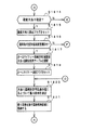
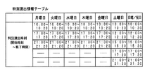
告知内容設定処理において、演出制御用マイクロコンピュータ100は、告知内容の設定を禁止する告知内容設定禁止フラグがセットされているか否かを確認する(ステップS1740)。この実施の形態では、後述するように、告知内容の設定処理が所定期間(告知内容設定禁止期間)禁止される。例えば、演出制御用マイクロコンピュータ100は、遊技店の開店時刻(例えば10:00)から閉店時刻(例えば23:00)の間には告知内容設定禁止フラグをセットするように制御し、告知内容設定処理の実行を禁止する。   In the notification content setting process, the production control microcomputer 100 checks whether or not a notification content setting prohibition flag for prohibiting setting of the notification content is set (step S1740). In this embodiment, as described later, notification content setting processing is prohibited for a predetermined period (notification content setting prohibition period). For example, the production control microcomputer 100 controls to set the notification content setting prohibition flag between the opening time (for example, 10:00) and the closing time (for example, 23:00) of the amusement store, and sets the notification content. Prohibit execution of processing.

告知内容設定禁止フラグがセットされていなければ(すなわち、告知内容設定処理の禁止期間でなければ)、演出制御用マイクロコンピュータ100は、告知内容を既に設定済みであることを示す告知内容設定フラグがセットされているか否かを確認する(ステップS1741)。セットされていなければ(すなわち、告知内容を未設定であれば)、演出制御用マイクロコンピュータ100は、操作ボタン120から検出信号を入力したか否かを確認する(ステップS1742)。すなわち、遊技店の店員などによって告知内容の設定操作が開始されたか否かを確認する。   If the notification content setting prohibition flag is not set (that is, not in the prohibition period of the notification content setting process), the production control microcomputer 100 has a notification content setting flag indicating that the notification content has already been set. It is confirmed whether it is set (step S1741). If it is not set (that is, if the notification content is not set), the production control microcomputer 100 checks whether or not a detection signal is input from the operation button 120 (step S 1742). That is, it is confirmed whether or not an operation for setting notification contents has been started by a store clerk or the like of the game store.

なお、ステップS1742で操作ボタン120からの検出信号を入力した後に、演出制御用マイクロコンピュータ100は、遊技中における操作であるか否か(例えば、所定の遊技演出中や背景画面選択中の操作か否か)を判断し、遊技中における操作でなければ、ステップS1743以降の処理に移行するようにしてもよい。また、ステップS1742で操作ボタン120からの検出信号を入力した後に、演出制御用マイクロコンピュータ100は、リアルタイムクロック353から時刻信号を入力し、現時刻が所定の告知内容設定禁止期間でないことを確認してからステップS1743以降の処理に移行するようにしてもよい。そのようにすれば、所定の告知内容設定禁止期間になってから遊技機1の電源投入が行われた場合であっても、確実に告知内容設定禁止期間における告知内容の設定操作を禁止することができる。   After the detection signal from the operation button 120 is input in step S 1742, the effect control microcomputer 100 determines whether or not the operation is during a game (for example, an operation during a predetermined game effect or a background screen selection). If it is not an operation during the game, the process may proceed to step S1743 and subsequent steps. Further, after inputting the detection signal from the operation button 120 in step S 1742, the production control microcomputer 100 inputs the time signal from the real-time clock 353, and confirms that the current time is not the predetermined notification content setting prohibition period. Then, the process may proceed to step S1743 and subsequent steps. By doing so, even if the gaming machine 1 is turned on after the predetermined notification content setting prohibition period, the setting operation of the notification content during the notification content setting prohibition period is surely prohibited. Can do.

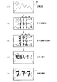
操作ボタン120から検出信号が入力されると(すなわち、告知内容の設定操作が開始されると)、演出制御用マイクロコンピュータ100は、告知内容の設定操作を促す旨の告知内容設定画面を可変表示装置9に表示させる(ステップS1743)。例えば、演出制御用マイクロコンピュータ100は、図13(a)に示す告知内容設定画面を可変表示装置9に表示させ、「おすすめ台」、「優良台」または「あま釘台」のいずれかの選択操作を促す。そして、演出制御用マイクロコンピュータ100は、操作ボタン120から検出信号が入力されるまで(すなわち、遊技店の店員などによって告知内容の設定操作が行われるまで)待つ(ステップS1744)。なお、告知内容設定の禁止期間になるまで操作ボタン120からの検出信号が入力されなかった場合には、演出制御用マイクロコンピュータ100は、告知内容設定禁止フラグをセットするとともに、そのまま告知内容設定処理を終了する。   When the detection signal is input from the operation button 120 (that is, when the notification content setting operation is started), the production control microcomputer 100 variably displays a notification content setting screen for prompting the notification content setting operation. The information is displayed on the device 9 (step S1743). For example, the production control microcomputer 100 displays the notification content setting screen shown in FIG. 13A on the variable display device 9, and selects any one of “recommended table”, “excellent table”, and “amanail table”. Encourage operation. Then, the production control microcomputer 100 waits until a detection signal is input from the operation button 120 (that is, until a notification content setting operation is performed by a store clerk or the like of the game store) (step S1744). If the detection signal from the operation button 120 is not input until the notification content setting prohibition period is reached, the effect control microcomputer 100 sets the notification content setting prohibition flag and also performs the notification content setting process. Exit.

操作ボタン120からの検出信号を入力すると(ステップS1744のY)、演出制御用マイクロコンピュータ100は、入力した検出信号に従って告知内容を選択する(ステップS1745)。例えば、操作ボタン120が十字キーである場合には、設定者(遊技店の店員など)は、図13(b)に示すように、十字キーである操作ボタン120を操作することによって、図13(a)に示す告知内容設定画面においてカーソルを移動させ、「A.おすすめ台」、「B.優良台」、「C.あま釘台」のいずれかを選択指示する。次いで、設定者は、決定ボタン(例えば、十字キーの真ん中)を押すことによって、選択した告知内容に決定する操作を行う。すると、演出制御用マイクロコンピュータ100は、設定者の操作に従って、告知内容を選択する。   When the detection signal from the operation button 120 is input (Y in step S1744), the effect control microcomputer 100 selects the notification content according to the input detection signal (step S1745). For example, when the operation button 120 is a cross key, as shown in FIG. 13B, a setter (such as a store clerk at a game shop) operates the operation button 120 that is a cross key, as shown in FIG. The cursor is moved on the notification content setting screen shown in (a), and one of “A. Recommended stand”, “B. Excellent stand”, and “C. Next, the setter performs an operation of determining the selected notification content by pressing a determination button (for example, the middle of the cross key). Then, the production control microcomputer 100 selects the notification content according to the operation of the setter.

次いで、そして、演出制御用マイクロコンピュータ100は、選択した告知内容を告知する告知演出を特定可能な告知演出情報を所定の告知演出情報格納領域に保存する(ステップS1746)。なお、この実施の形態では、所定の告知演出情報格納領域は、バックアップRAM356に確保される。   Next, the effect control microcomputer 100 stores notification effect information capable of specifying the notification effect for notifying the selected notification content in a predetermined notification effect information storage area (step S1746). In this embodiment, a predetermined notification effect information storage area is secured in the backup RAM 356.

図14は、ステップS1746で保存される告知演出情報の例を示す説明図である。図14に示すように、例えば、おすすめ台である旨の告知内容を選択した場合には、演出制御用マイクロコンピュータ100は、おすすめ台である旨の告知演出を特定可能な告知演出情報として告知演出識別子「K01」を所定の告知演出情報格納領域に保存する。また、例えば、優良台である旨の告知内容を選択した場合には、演出制御用マイクロコンピュータ100は、優良台である旨の告知演出を特定可能な告知演出情報として告知演出識別子「K02」を所定の告知演出情報格納領域に保存する。例えば、あま釘台である旨の告知内容を選択した場合には、演出制御用マイクロコンピュータ100は、あま釘台である旨の告知演出を特定可能な告知演出情報として告知演出識別子「K03」を所定の告知演出情報格納領域に保存する。   FIG. 14 is an explanatory diagram showing an example of notification effect information stored in step S1746. As shown in FIG. 14, for example, when the notification content indicating that it is a recommended stand is selected, the effect control microcomputer 100 provides the notification effect as notification effect information that can specify the notification effect indicating that it is the recommended stand. The identifier “K01” is stored in a predetermined notification effect information storage area. Further, for example, when the notification content indicating that it is an excellent stand is selected, the effect control microcomputer 100 sets the notification effect identifier “K02” as notification effect information that can specify the notification effect indicating that it is an excellent stand. The information is stored in a predetermined notification effect information storage area. For example, when the notification content indicating that it is an Ama nail base is selected, the effect control microcomputer 100 uses the notification effect identifier “K03” as the notification effect information that can specify the notification effect indicating that it is an Ama nail base. The information is stored in a predetermined notification effect information storage area.

上記の処理によって、告知内容として、遊技者に対して告知する情報(「おすすめ台」や「優良台」、「あま釘台」などの情報)と、その告知する情報に対応する演出とが選択され、告知演出情報として記憶される。   As a result of the above processing, information to be notified to the player (information such as “Recommended stand”, “Good stand”, “Ama nail stand”) and the production corresponding to the information to be notified are selected. And stored as notification effect information.

次いで、演出制御用マイクロコンピュータ100は、ステップS1746で設定した告知内容を自動消去する時刻(告知内容消去時刻)をセットする(ステップS1747)。この実施の形態では、ステップS1747でセットした告知内容消去時刻にもとづいて、遊技中に告知内容が消去されなくても、遊技店の閉店時刻(例えば、23:00)に告知内容が自動的に消去される。なお、遊技店の閉店時刻ではなく、例えば、リアルタイムクロック353からの日付信号や時刻信号にもとづいて告知内容の設定時刻を記録し、告知内容を設定してから所定期間経過したことを検出したときに告知内容を自動消去するようにしてもよい。例えば、演出制御用マイクロコンピュータ100は、告知内容設定フラグがセットされた時刻の24時間後に告知内容を自動消去するように、告知内容消去時刻を自動設定してもよい。また、あらかじめ定められた告知内容消去時刻を設定するのではなく、複数の時刻から告知内容消去時刻を選択できるようにしてもよい。この場合、例えば、演出制御用マイクロコンピュータ100は、複数の時刻を含む告知内容消去時刻選択画面を可変表示装置9に表示し、操作ボタン120からの検出信号にもとづいて、遊技店の店員などによって選択された時刻を告知内容消去時刻として設定するようにしてもよい。そして、演出制御用マイクロコンピュータ100は、告知内容設定フラグをセットして(ステップS1748)、処理を終了する。   Next, the production control microcomputer 100 sets a time (notification content erasing time) for automatically erasing the notification content set in step S1746 (step S1747). In this embodiment, based on the notification content deletion time set in step S1747, even if the notification content is not deleted during the game, the notification content is automatically set at the game store closing time (for example, 23:00). Erased. In addition, when the setting time of the notification content is recorded based on the date signal and the time signal from the real time clock 353 instead of the closing time of the game store, and it is detected that a predetermined period has elapsed since the notification content was set The notification content may be automatically deleted. For example, the production control microcomputer 100 may automatically set the notification content deletion time so that the notification content is automatically deleted 24 hours after the time when the notification content setting flag is set. Further, instead of setting a predetermined notification content deletion time, the notification content deletion time may be selected from a plurality of times. In this case, for example, the production control microcomputer 100 displays a notification content erasing time selection screen including a plurality of times on the variable display device 9, and based on a detection signal from the operation button 120, by a store clerk or the like of the amusement store. The selected time may be set as the notification content erasing time. Then, the production control microcomputer 100 sets the notification content setting flag (step S1748) and ends the process.

ステップS1740で告知内容設定禁止フラグがセットされていれば(すなわち、告知内容設定処理の禁止期間であれば)、演出制御用マイクロコンピュータ100は、リアルタイムクロック353から現時刻信号(時、分、秒)を入力する(ステップS1749)。次いで、演出制御用マイクロコンピュータ100は、入力した現時刻信号にもとづいて、現時刻が所定期間(告知内容設定処理の禁止期間)であるか否かを確認する(ステップS1750)。例えば、演出制御用マイクロコンピュータ100は、現時刻が遊技店の開店時刻(10:00)から閉店時刻(23:00)までの間の期間であるか否かを確認する。現時刻が所定期間であれば、そのまま処理を終了する。現時刻が所定期間でなければ(すなわち、告知内容設定処理の禁止期間でなくなれば)、演出制御用マイクロコンピュータ100は、告知内容設定禁止フラグをリセットし(ステップS1751)、処理を終了する。   If the notification content setting prohibition flag is set in step S1740 (that is, during the notification content setting processing prohibition period), the production control microcomputer 100 receives the current time signal (hour, minute, second) from the real time clock 353. ) Is input (step S1749). Next, the production control microcomputer 100 checks whether or not the current time is a predetermined period (a period during which the notification content setting process is prohibited) based on the input current time signal (step S1750). For example, the production control microcomputer 100 checks whether or not the current time is a period from the opening time (10:00) of the amusement shop to the closing time (23:00). If the current time is a predetermined period, the process is terminated as it is. If the current time is not the predetermined period (that is, if it is not the prohibition period for the notification content setting process), the production control microcomputer 100 resets the notification content setting prohibition flag (step S1751) and ends the process.

ステップS1741で告知内容設定フラグがセットされていれば(すなわち、既に告知内容が設定されていれば)、演出制御用マイクロコンピュータ100は、リアルタイムクロック353から現時刻信号(時、分、秒)を入力する(ステップS1752)。次いで、演出制御用マイクロコンピュータ100は、入力した現時刻信号にもとづいて、現時刻が所定期間(告知内容設定処理の禁止期間)であるか否かを確認する(ステップS1753)。例えば、演出制御用マイクロコンピュータ100は、現時刻が遊技店の開店時刻(10:00)から閉店時刻(23:00)までの間の期間であるか否かを確認する。現時刻が所定時間でなければ、ステップS1755に移行する。現時刻が所定期間であれば(すなわち、告知内容設定処理の禁止期間になれば)、演出制御用マイクロコンピュータ100は、告知内容設定禁止フラグをセットする(ステップS1754)。   If the notification content setting flag is set in step S1741 (that is, if the notification content has already been set), the production control microcomputer 100 receives the current time signal (hour, minute, second) from the real time clock 353. Input (step S1752). Next, the production control microcomputer 100 checks whether or not the current time is a predetermined period (a period during which the notification content setting process is prohibited) based on the input current time signal (step S1753). For example, the production control microcomputer 100 checks whether or not the current time is a period from the opening time (10:00) of the amusement shop to the closing time (23:00). If the current time is not a predetermined time, the process proceeds to step S1755. If the current time is a predetermined period (that is, if the notification content setting process is prohibited), the production control microcomputer 100 sets a notification content setting prohibition flag (step S1754).

なお、この実施の形態では、一例として所定期間(告知内容設定処理の禁止期間)が遊技店の開店時刻(10:00)から閉店時刻(23:00)までの期間である場合を説明するが、この実施の形態で示した期間に限らず、例えば、所定期間を複数設けてもよい。そして、演出制御用マイクロコンピュータ100は、現時刻が複数の所定期間のいずれかに該当すると判断すると、告知内容設定禁止フラグをセットするようにしてもよい。   In this embodiment, as an example, a case where the predetermined period (the prohibition period of the notification content setting process) is a period from the opening time (10:00) of the amusement shop to the closing time (23:00) will be described. For example, a plurality of predetermined periods may be provided without being limited to the period shown in this embodiment. Then, when it is determined that the current time corresponds to one of a plurality of predetermined periods, the production control microcomputer 100 may set a notification content setting prohibition flag.

次いで、演出制御用マイクロコンピュータ100は、現時刻が所定の告知内容消去時刻(例えば、遊技店の閉店時刻である23:00)であるか否かを確認する(ステップS1755)。現時刻が所定の告知内容消去時刻でなければ、そのまま処理を終了する。現時刻が所定の告知内容消去時刻であれば、演出制御用マイクロコンピュータ100は、所定の告知演出情報格納領域に保存する告知演出情報を消去する(ステップS1756)とともに、告知内容設定フラグをリセットする(ステップS1757)。   Next, the production control microcomputer 100 checks whether or not the current time is a predetermined notification content erasing time (for example, 23:00, which is the closing time of the amusement store) (step S1755). If the current time is not a predetermined notification content erasing time, the process ends. If the current time is the predetermined notification content deletion time, the production control microcomputer 100 deletes the notification production information stored in the predetermined notification production information storage area (step S1756) and resets the notification content setting flag. (Step S1757).

ステップS1742で操作ボタン120からの検出信号を入力しなかった場合(すなわち、告知内容の設定操作が行われなかった場合)には、演出制御用マイクロコンピュータ100は、リアルタイムクロック353から現時刻信号(時、分、秒)を入力する(ステップS1758)。次いで、演出制御用マイクロコンピュータ100は、入力した現時刻信号にもとづいて、現時刻が所定期間(告知内容設定処理の禁止期間)であるか否かを確認する(ステップS1759)。例えば、演出制御用マイクロコンピュータ100は、現時刻が遊技店の開店時刻(10:00)から閉店時刻(23:00)までの間の期間であるか否かを確認する。現時刻が所定時間でなければ、そのまま処理を終了する。現時刻が所定期間であれば(すなわち、告知内容設定処理の禁止期間になれば)、演出制御用マイクロコンピュータ100は、告知内容設定禁止フラグをセットし(ステップS1760)、処理を終了する。   When the detection signal from the operation button 120 is not input in step S 1742 (that is, when the notification content setting operation is not performed), the effect control microcomputer 100 receives the current time signal (from the real-time clock 353). (Hour, minute, second) is input (step S1758). Next, the production control microcomputer 100 confirms whether or not the current time is a predetermined period (prohibition period for the notification content setting process) based on the input current time signal (step S1759). For example, the production control microcomputer 100 checks whether or not the current time is a period from the opening time (10:00) of the amusement shop to the closing time (23:00). If the current time is not a predetermined time, the process is terminated as it is. If the current time is a predetermined period (that is, if the notification content setting process is prohibited), the production control microcomputer 100 sets a notification content setting prohibition flag (step S1760) and ends the process.

なお、図12に示す例では、操作ボタン120からの検出信号にもとづいて告知内容の設定を行う場合を示しているが、例えば、ランプドライバ基板35に設けられた設定スイッチ354からのオン/オフ信号にもとづいて告知内容を設定するようにしてもよい。   In the example shown in FIG. 12, the notification content is set based on the detection signal from the operation button 120, but for example, on / off from the setting switch 354 provided on the lamp driver board 35. The notification content may be set based on the signal.

また、この実施の形態では、告知内容の設定が可能な期間(告知内容設定処理の禁止期間以外の期間)に一回だけ告知内容の設定が可能である場合を示しているが、告知内容の設定が可能な期間内に何回でも告知内容の設定が変更可能に構成してもよい。この場合、例えば、図12に示す告知内容設定処理において、ステップS1740で告知内容設定禁止フラグがセットされていなければ、ステップS1741を行わずにそのままステップS1742に移行するようにするとともに、ステップS1760で告知内容設定禁止フラグをセットした後にステップS1752〜S1757の処理を実行するようにすればよい。   In this embodiment, the case where the notification content can be set only once during the period during which the notification content can be set (a period other than the prohibition period of the notification content setting process) is shown. You may comprise so that the setting of notification content can be changed any number of times within the period which can be set. In this case, for example, in the notification content setting process shown in FIG. 12, if the notification content setting prohibition flag is not set in step S1740, the process proceeds to step S1742 without performing step S1741, and in step S1760. The processing of steps S1752 to S1757 may be executed after setting the notification content setting prohibition flag.

図15は、メイン処理におけるコマンド解析処理(ステップS705)を示すフローチャートである。遊技制御用マイクロコンピュータ560から送信された演出制御コマンドは、INT割込で実行されるコマンド受信処理において、コマンド受信バッファに格納される。コマンド解析処理において、演出制御用マイクロコンピュータ100は、まず、コマンド受信バッファに受信コマンドが格納されているか否か確認する(ステップS1611)。格納されているか否かは、コマンド受信個数カウンタの値と読出ポインタとを比較することによって判定される。両者が一致している場合が、受信コマンドが格納されていない場合である。コマンド受信バッファに受信コマンドが格納されている場合には、演出制御用マイクロコンピュータ100は、コマンド受信バッファから受信コマンドを読み出す(ステップS1612)。   FIG. 15 is a flowchart showing command analysis processing (step S705) in the main processing. The effect control command transmitted from the game control microcomputer 560 is stored in the command reception buffer in the command reception process executed by the INT interrupt. In the command analysis process, the production control microcomputer 100 first checks whether or not a reception command is stored in the command reception buffer (step S1611). Whether it is stored or not is determined by comparing the value of the command reception number counter with the read pointer. The case where both match is the case where the received command is not stored. If the reception command is stored in the command reception buffer, the effect control microcomputer 100 reads the reception command from the command reception buffer (step S1612).

なお、INT割込で実行されるコマンド受信処理で受信した演出制御コマンドをコマンド受信バッファに格納する際に、演出制御用マイクロコンピュータ100は、受信したコマンドがプログラム上存在する演出制御コマンドであるか否かを確認するようにしてもよい。例えば、演出制御用マイクロコンピュータ100は、受信コマンドの1バイト目のMODEデータが「80」や「8C」、「A0」などプログラム上存在するものであるか否かを確認し、プログラム上存在しないMODEデータであれば、データ化けなどの原因によって演出制御コマンドを正しく受信できなかったと判断して、受信コマンドを破棄してもよい。また、プログラム上存在するMODEデータであっても、2バイト目のEXTデータがそのMODEデータに対してプログラム上存在するものであるか否かを確認し、プログラム上存在しないEXTデータであれば、データ化けなどの原因によって演出制御コマンドを正しく受信できなかったと判断して、受信コマンドを破棄してもよい。この場合、受信コマンドはコマンド受信バッファに格納されず、コマンド解析処理において、演出制御コマンドを受信していないものとして処理される。   When the effect control command received by the command reception process executed by the INT interrupt is stored in the command reception buffer, the effect control microcomputer 100 determines whether the received command is an effect control command existing in the program. You may make it confirm whether or not. For example, the production control microcomputer 100 checks whether the MODE data of the first byte of the received command exists on the program such as “80”, “8C”, “A0”, and does not exist on the program. If it is MODE data, it may be determined that the effect control command has not been correctly received due to garbled data or the like, and the received command may be discarded. Further, even if the MODE data exists in the program, it is confirmed whether or not the EXT data of the second byte is present in the program with respect to the MODE data. If the EXT data does not exist in the program, It may be determined that the effect control command has not been correctly received due to data corruption or the like, and the received command may be discarded. In this case, the received command is not stored in the command reception buffer, and is processed in the command analysis process as if the effect control command has not been received.

受信した演出制御コマンドが、変動パターン指定の演出制御コマンド(変動パターンコマンド)であれば(ステップS1613)、演出制御用マイクロコンピュータ100は、受信した変動パターンコマンドに示される変動パターンをセーブする(ステップS1614)。具体的には、そのコマンドのEXTデータをRAMにおける変動パターンデータ格納領域に格納する。また、演出制御用マイクロコンピュータ100は、変動パターンコマンドを受信したことを示す変動パターン受信フラグをセットする(ステップS1615)。なお、変動パターンコマンドは、遊技制御用マイクロコンピュータ560によって変動パターン設定処理(ステップS301参照)でセットした変動パターンにもとづいて送信される。   If the received effect control command is an effect control command (variation pattern command) for specifying a variation pattern (step S1613), the effect control microcomputer 100 saves the variation pattern indicated in the received variation pattern command (step S1613). S1614). Specifically, the EXT data of the command is stored in the fluctuation pattern data storage area in the RAM. Further, the production control microcomputer 100 sets a variation pattern reception flag indicating that the variation pattern command has been received (step S1615). The variation pattern command is transmitted by the game control microcomputer 560 based on the variation pattern set in the variation pattern setting process (see step S301).

受信した演出制御コマンドが、表示結果コマンドであれば(ステップS1616)、演出制御用マイクロコンピュータ100は、受信した表示結果コマンドに示される表示結果をセーブする(ステップS1617)。具体的には、そのコマンドのEXTデータをRAMにおける表示結果データ格納領域に格納する。また、演出制御用マイクロコンピュータ100は、表示結果コマンドを受信したことを示す表示結果受信フラグをセットする(ステップS1618)。なお、表示結果コマンドは、遊技制御用マイクロコンピュータ560によって特別図柄通常処理(ステップS300参照)で演出図柄情報バッファにセットされた演出指定値にもとづいて、演出図柄コマンド制御処理(ステップS29参照)で送信される。   If the received effect control command is a display result command (step S1616), the effect control microcomputer 100 saves the display result indicated by the received display result command (step S1617). Specifically, the EXT data of the command is stored in the display result data storage area in the RAM. In addition, the effect control microcomputer 100 sets a display result reception flag indicating that the display result command has been received (step S1618). The display result command is generated in the effect symbol command control process (see step S29) based on the effect designation value set in the effect symbol information buffer in the special symbol normal process (see step S300) by the game control microcomputer 560. Sent.

また、受信した演出制御コマンドが、ファンファーレ指定の演出制御コマンド(ファンファーレコマンド)であれば(ステップS1619)、演出制御用マイクロコンピュータ100は、そのコマンドのEXTデータをRAMにおけるファンファーレデータ格納領域に格納し(ステップS1620)、ファンファーレコマンドを受信したことを示すファンファーレフラグをセットする(ステップS1621)。なお、ファンファーレコマンドは、遊技制御用マイクロコンピュータ560によって特別図柄停止処理(ステップS303参照)で送信される。   If the received effect control command is a fanfare-designated effect control command (fanfare command) (step S1619), the effect control microcomputer 100 stores the EXT data of the command in the fanfare data storage area in the RAM. (Step S1620), a fanfare flag indicating that the fanfare command has been received is set (step S1621). The fanfare command is transmitted by the game control microcomputer 560 in a special symbol stop process (see step S303).

また、受信した演出制御コマンドが、エンディング指定の演出制御コマンド(エンディングコマンド)であれば(ステップS1622)、演出制御用マイクロコンピュータ100は、そのコマンドのEXTデータをRAMにおけるエンディングデータ格納領域に格納し(ステップS1623)、エンディングコマンドを受信したことを示すエンディングフラグをセットする(ステップS1624)。なお、エンディングコマンドは、遊技制御用マイクロコンピュータ560によって大当り終了処理(ステップS307参照)で送信される。   If the received effect control command is an ending designation effect control command (ending command) (step S1622), the effect control microcomputer 100 stores the EXT data of the command in the ending data storage area in the RAM. (Step S1623), an ending flag indicating that the ending command has been received is set (step S1624). The ending command is transmitted by the game control microcomputer 560 in the big hit end process (see step S307).

また、受信した演出制御コマンドが、デモ表示コマンドであれば(ステップS1625)、演出制御用マイクロコンピュータ100は、デモ表示コマンドを受信したことを示すデモ表示受信フラグをセットする(ステップS1626)。   If the received production control command is a demonstration display command (step S1625), the production control microcomputer 100 sets a demonstration display reception flag indicating that the demonstration display command has been received (step S1626).

ステップS1612で読み出した受信コマンドがその他の演出制御コマンドである場合には、演出制御用マイクロコンピュータ100は、受信コマンドに対応するフラグをセットする(ステップS1627)。例えば、演出制御用マイクロコンピュータ100は、受信コマンドが飾り図柄停止指定コマンドである場合には、飾り図柄停止指定コマンドを受信したことを示す飾り図柄停止指定受信フラグをセットする。   If the received command read in step S1612 is another effect control command, the effect control microcomputer 100 sets a flag corresponding to the received command (step S1627). For example, when the received command is a decorative symbol stop designation command, the effect control microcomputer 100 sets a decorative symbol stop designation reception flag indicating that the decorative symbol stop designation command has been received.

図16は、メイン処理におけるデモ表示プロセス処理(ステップS706)を示すフローチャートである。デモ表示プロセス処理では、演出制御用マイクロコンピュータ100は、デモ表示プロセスフラグの値に応じてステップS760,S761のうちのいずれかの処理を行う。各処理において、以下のような処理を実行する。   FIG. 16 is a flowchart showing the demo display process process (step S706) in the main process. In the demonstration display process, the effect control microcomputer 100 performs one of steps S760 and S761 according to the value of the demonstration display process flag. In each process, the following process is executed.

デモ表示開始処理(ステップS760):デモ表示コマンドを受信したことにもとづいて、デモンストレーション演出を開始する。この場合、現時刻が所定の特別デモ実行時刻であるか否かを確認する。そして、現時刻が所定の特別デモ実行時刻でなければ通常のデモンストレーション演出を開始し、現時刻が所定の特別デモ実行時刻であれば特別のデモンストレーション演出を開始する。   Demo display start process (step S760): The demonstration effect is started based on the reception of the demo display command. In this case, it is confirmed whether or not the current time is a predetermined special demonstration execution time. If the current time is not a predetermined special demonstration execution time, a normal demonstration effect is started. If the current time is a predetermined special demonstration execution time, a special demonstration effect is started.

デモ表示中処理(ステップS761):デモ表示コマンドを受信したことにもとづいて、デモンストレーション演出を継続して実行する。また、デモ表示コマンドを受信していなければ、デモンストレーション演出を終了する。デモンストレーション演出を継続して実行する場合、特別のデモンストレーション演出を実行している場合には、そのまま特別のデモンストレーション演出を継続して実行する。通常のデモンストレーション演出を実行している場合には、現時刻が所定の特別デモ実行時刻であるか否かを確認する。そして、現時刻が所定の特別デモ実行時刻でなければそのまま通常のデモンストレーション演出を継続して実行し、現時刻が所定の特別デモ実行時刻であれば特別のデモンストレーション演出に切り替える。   Demo display processing (step S761): The demonstration effect is continuously executed based on the reception of the demo display command. If the demonstration display command has not been received, the demonstration effect ends. When the demonstration effect is continuously executed, when the special demonstration effect is being executed, the special demonstration effect is continuously executed as it is. When a normal demonstration performance is being executed, it is confirmed whether or not the current time is a predetermined special demonstration execution time. Then, if the current time is not a predetermined special demonstration execution time, the normal demonstration performance is continuously executed as it is, and if the current time is a predetermined special demonstration execution time, the special demonstration performance is switched.

図17は、デモ表示プロセス処理におけるデモ表示開始処理(ステップS760)を示すフローチャートである。デモ表示開始処理において、演出制御用マイクロコンピュータ100は、まず、デモ表示受信フラグがセットされているか否かを確認する(ステップS7601)。セットされていれば、演出制御用マイクロコンピュータ100は、デモ表示受信フラグをリセットするとともに(ステップS7602)、リアルタイムクロック353から現時刻信号(時、分、秒)を入力する(ステップS7603)。そして、入力した現時刻信号にもとづいて、現時刻が所定の特別デモ実行時刻(例えば、9:30から10:00までの間の9:30、9:40、9:50、10:00の4つの時刻)であるか否かを確認する(ステップS7604)。   FIG. 17 is a flowchart showing a demo display start process (step S760) in the demo display process. In the demonstration display start process, the production control microcomputer 100 first checks whether or not the demonstration display reception flag is set (step S7601). If set, the production control microcomputer 100 resets the demonstration display reception flag (step S7602) and inputs the current time signal (hour, minute, second) from the real-time clock 353 (step S7603). Then, based on the input current time signal, the current time is a predetermined special demonstration execution time (for example, 9:30, 9:40, 9:50, 10:00 between 9:30 and 10:00). It is confirmed whether it is (four times) (step S7604).

所定の特別デモ実行時刻でなければ、演出制御用マイクロコンピュータ100は、通常のデモンストレーション演出に応じたプロセスデータを選択する(ステップS7605)。所定の特別デモ実行時刻であれば、演出制御用マイクロコンピュータ100は、通常のデモンストレーション演出とは異なる演出態様の特別のデモンストレーション演出に応じたプロセスデータを選択するとともに(ステップS7606)、特別のデモンストレーション演出を実行することを示す特別デモ表示フラグをセットする(ステップS7607)。   If it is not the predetermined special demonstration execution time, the production control microcomputer 100 selects process data corresponding to the normal demonstration production (step S7605). If it is a predetermined special demonstration execution time, the production control microcomputer 100 selects process data corresponding to the special demonstration production in a production mode different from the normal demonstration production (step S7606), and the special demonstration production. Is set (step S7607).

次いで、演出制御用マイクロコンピュータ100は、選択したプロセスデータ1におけるプロセスタイマ設定値をプロセスタイマに設定してプロセスタイマをスタートさせる(ステップS7608)。次いで、演出制御用マイクロコンピュータ100は、プロセスデータ1の内容(表示制御実行データ1、ランプ制御実行データ1、音番号データ1)に従って演出装置(可変表示装置9、各種ランプ、スピーカ27)の制御を実行する(ステップS7609)。例えば、演出制御用マイクロコンピュータ100は、可変表示装置9を用いて所定の動画像を表示させることによってデモンストレーション演出(通常のデモンストレーション演出または特別のデモンストレーション演出)を開始する。   Next, the production control microcomputer 100 sets the process timer set value in the selected process data 1 to the process timer and starts the process timer (step S7608). Next, the production control microcomputer 100 controls the production device (variable display device 9, various lamps, speaker 27) according to the contents of the process data 1 (display control execution data 1, lamp control execution data 1, sound number data 1). Is executed (step S7609). For example, the effect control microcomputer 100 starts a demonstration effect (a normal demonstration effect or a special demonstration effect) by displaying a predetermined moving image using the variable display device 9.

そして、演出制御用マイクロコンピュータ100は、デモ表示プロセスフラグの値をデモ表示中処理(ステップS761)を示す値に更新する(ステップS7610)。   Then, the effect control microcomputer 100 updates the value of the demonstration display process flag to a value indicating the demonstration display process (step S761) (step S7610).

図18は、デモ表示プロセス処理におけるデモ表示中処理(ステップS761)を示すフローチャートである。デモ表示中処理において、演出制御用マイクロコンピュータ100は、まず、デモ表示受信フラグがセットされているか否かを確認する(ステップS7651)。セットされていれば、演出制御用マイクロコンピュータ100は、デモ表示受信フラグをリセットするとともに(ステップS7652)、特別デモ表示フラグがセットされているか否かを確認する(ステップS7653)。   FIG. 18 is a flowchart showing the process during demonstration display (step S761) in the demonstration display process. In the demonstration display processing, the production control microcomputer 100 first checks whether or not the demonstration display reception flag is set (step S7651). If set, the production control microcomputer 100 resets the demonstration display reception flag (step S7652) and confirms whether or not the special demonstration display flag is set (step S7653).

特別デモ表示フラグがセットされていれば、演出制御用マイクロコンピュータ100は、そのままステップS7654に移行する。すなわち、既に特別のデモンストレーション演出を実行中である場合であるので、演出制御用マイクロコンピュータ100は、そのまま特別のデモンストレーション演出を継続して実行する。   If the special demonstration display flag is set, the production control microcomputer 100 proceeds to step S7654 as it is. That is, since the special demonstration effect is already being executed, the effect control microcomputer 100 continues to execute the special demonstration effect as it is.

特別デモ表示フラグがセットされていなければ、演出制御用マイクロコンピュータ100は、リアルタイムクロック353から現時刻信号(時、分、秒)を入力する(ステップS7659)。そして、入力した現時刻信号にもとづいて、現時刻が所定の特別デモ実行時刻(例えば、9:30から10:00までの間の9:30、9:40、9:50、10:00の4つの時刻)であるか否かを確認する(ステップS7660)。   If the special demonstration display flag is not set, the production control microcomputer 100 inputs the current time signal (hour, minute, second) from the real-time clock 353 (step S7659). Then, based on the input current time signal, the current time is a predetermined special demonstration execution time (for example, 9:30, 9:40, 9:50, 10:00 between 9:30 and 10:00). It is confirmed whether it is (four times) (step S7606).

所定の特別デモ実行時刻でなければ、演出制御用マイクロコンピュータ100は、ステップS7654に移行する。すなわち、現時刻が所定の特別デモ実行時刻でないので、演出制御用マイクロコンピュータ100は、そのまま通常のデモンストレーション演出を継続して実行する。   If it is not the predetermined special demonstration execution time, the production control microcomputer 100 proceeds to step S7654. That is, since the current time is not a predetermined special demonstration execution time, the production control microcomputer 100 continues to execute the normal demonstration production as it is.

所定の特別デモ実行時刻であれば、演出制御用マイクロコンピュータ100は、通常のデモンストレーション演出とは異なる演出態様の特別のデモンストレーション演出に応じたプロセスデータに切り替える(ステップS7661)。   If it is a predetermined special demonstration execution time, the production control microcomputer 100 switches to process data corresponding to the special demonstration production having a production mode different from the normal demonstration production (step S7661).

次いで、演出制御用マイクロコンピュータ100は、切り替えたプロセスデータ1におけるプロセスタイマ設定値をプロセスタイマに設定してプロセスタイマをスタートさせる(ステップS7662)。次いで、演出制御用マイクロコンピュータ100は、プロセスデータ1の内容(表示制御実行データ1、ランプ制御実行データ1、音番号データ1)に従って演出装置(可変表示装置9、各種ランプ、スピーカ27)の制御を実行する(ステップS7663)。例えば、演出制御用マイクロコンピュータ100は、可変表示装置9を用いて所定の動画像を表示させることによって特別のデモンストレーション演出を開始する。そして、演出制御用マイクロコンピュータ100は、特別デモ表示フラグをセットし(ステップS7664)、処理を終了する。   Next, the production control microcomputer 100 sets the process timer set value in the switched process data 1 to the process timer and starts the process timer (step S7662). Next, the production control microcomputer 100 controls the production device (variable display device 9, various lamps, speaker 27) according to the contents of the process data 1 (display control execution data 1, lamp control execution data 1, sound number data 1). Is executed (step S7663). For example, the production control microcomputer 100 starts a special demonstration production by displaying a predetermined moving image using the variable display device 9. Then, the production control microcomputer 100 sets a special demonstration display flag (step S7664) and ends the process.

ステップS7654では、演出制御用マイクロコンピュータ100は、プロセスタイマを1減算する(ステップS7654)。次いで、演出制御用マイクロコンピュータ100は、プロセスデータnの内容に従って演出装置(可変表示装置9、各種ランプ、スピーカ27)の制御を実行する(ステップS7655)。例えば、演出制御用マイクロコンピュータ100は、可変表示装置9を用いて所定の動画像を表示させることによってデモンストレーション演出(通常のデモンストレーション演出または特別のデモンストレーション演出)を継続して実行する。   In step S7654, the production control microcomputer 100 subtracts 1 from the process timer (step S7654). Next, the effect control microcomputer 100 executes control of the effect device (variable display device 9, various lamps, speaker 27) according to the contents of the process data n (step S7655). For example, the effect control microcomputer 100 continuously executes a demonstration effect (a normal demonstration effect or a special demonstration effect) by displaying a predetermined moving image using the variable display device 9.

次いで、演出制御用マイクロコンピュータ100は、プロセスタイマがタイムアウトしていないかどうかを確認し(ステップS7656)、プロセスタイマがタイムアウトしていれば、プロセスデータの切替を行う(ステップS7657)。すなわち、プロセステーブルにおける次に設定されているプロセスデータ(表示制御実行データ、ランプ制御実行データおよび音番号データ)に切り替える。そして、次のプロセスデータにおけるプロセスタイマ設定値をプロセスタイマに設定してプロセスタイマをスタートさせて(ステップS7658)、処理を終了する。   Next, the production control microcomputer 100 checks whether or not the process timer has timed out (step S7656). If the process timer has timed out, the process data is switched (step S7657). That is, the process data (display control execution data, lamp control execution data, and sound number data) set next in the process table is switched. Then, the process timer setting value in the next process data is set in the process timer, the process timer is started (step S7658), and the process is terminated.

ステップS7651でデモ表示フラグがセットされていなければ、演出制御用マイクロコンピュータ100は、デモ表示プロセスフラグの値をデモ表示開始処理(ステップS760)を示す値に更新する(ステップS7665)。すなわち、変動開始可能となるか保留記憶数が0でなくなり遊技制御用マイクロコンピュータ560からデモ表示コマンドを受信しなかった場合であるので、演出制御用マイクロコンピュータ100は、デモンストレーション演出を終了する。なお、ステップS7665では、演出制御用マイクロコンピュータ100は、特別デモ表示フラグがセットされていれば、そのフラグをリセットする。   If the demonstration display flag is not set in step S7651, the effect control microcomputer 100 updates the value of the demonstration display process flag to a value indicating the demonstration display start process (step S760) (step S7665). In other words, since it is possible to start the change or the reserved memory number is not 0 and the demonstration display command is not received from the game control microcomputer 560, the effect control microcomputer 100 ends the demonstration effect. In step S7665, if the special demonstration display flag is set, the production control microcomputer 100 resets the flag.

上記の処理が実行されることによって、この実施の形態では、リアルタイムクロック353から入力した現時刻信号にもとづいて、所定の特別デモ実行時刻であれば、通常のデモンストレーション演出とは異なる特別のデモンストレーション演出を行う。そのようにすることによって、例えば、リアルタイムクロック353が計時する時間にもとづいて複数の遊技機で一斉に演出を実行する場合に、デモンストレーション演出の開始タイミングやさらに動作の同期を視覚的に確認することによって、複数の遊技機間でリアルタイムクロック353が計時する時間にずれが生じているか否かを確認することができる。そのため、視覚による確認結果にもとづいてリアルタイムクロック353が計時する時間のずれに対する処理を講じることができ、遊技機の製造コストを増加させることなく、演出の実行タイミングが複数の遊技機間でずれてしまう事態を防止するとともに、遊技者に与える演出効果が低減してしまう事態を防止することができる。   By executing the above processing, in this embodiment, a special demonstration effect different from a normal demonstration effect is obtained at a predetermined special demonstration execution time based on the current time signal input from the real-time clock 353. I do. By doing so, for example, when the presentation is executed simultaneously with a plurality of gaming machines based on the time counted by the real-time clock 353, the demonstration presentation start timing and the operation synchronization are visually confirmed. Thus, it can be confirmed whether or not there is a difference in the time measured by the real-time clock 353 among the plurality of gaming machines. Therefore, processing for the time lag timed by the real-time clock 353 can be taken based on the visual confirmation result, and the execution timing of the production is shifted between the plurality of gaming machines without increasing the manufacturing cost of the gaming machine. Can be prevented, and a situation where the effect of presentation to the player is reduced can be prevented.

図19は、メイン処理における演出制御プロセス処理(ステップS707)を示すフローチャートである。演出制御プロセス処理では、演出制御用マイクロコンピュータ100は、演出制御プロセスフラグの値に応じてステップS800〜S807のうちのいずれかの処理を行う。各処理において、以下のような処理を実行する。   FIG. 19 is a flowchart showing the effect control process (step S707) in the main process. In the effect control process, the effect control microcomputer 100 performs one of steps S800 to S807 according to the value of the effect control process flag. In each process, the following process is executed.

変動パターンコマンド受信待ち処理(ステップS800):コマンド受信割込処理によって、変動パターン指定の演出制御コマンド(変動パターンコマンド)を受信したか否か確認する。具体的には、変動パターンコマンドが受信されたことを示すフラグ(変動パターン受信フラグ)がセットされたか否か確認する。変動パターン受信フラグは、演出制御用マイクロコンピュータ100が実行するコマンド解析処理で可変表示装置9における飾り図柄の変動パターン指定の演出制御コマンドが受信されたことが確認された場合にセットされる(ステップS1615参照)。   Fluctuation pattern command reception waiting process (step S800): It is confirmed whether or not an effect control command (fluctuation pattern command) specifying a fluctuation pattern has been received by the command reception interrupt process. Specifically, it is confirmed whether or not a flag (variation pattern reception flag) indicating that a variation pattern command has been received is set. The variation pattern reception flag is set when it is confirmed by the command analysis process executed by the effect control microcomputer 100 that an effect control command for designating a decorative pattern variation pattern in the variable display device 9 has been received (step S100). (See S1615).

飾り図柄変動開始処理(ステップS801):飾り図柄の変動が開始されるように制御する。また、変動時間タイマに変動時間に相当する値を設定し、使用するプロセステーブルを選択するとともに、プロセステーブルの最初に設定されているプロセスタイマ設定値をプロセスタイマに設定する。   Decoration symbol variation start processing (step S801): Control is performed so that the variation of the ornament symbol is started. In addition, a value corresponding to the variation time is set in the variation time timer, the process table to be used is selected, and the process timer setting value set at the beginning of the process table is set in the process timer.

飾り図柄変動中処理(ステップS802):変動パターンを構成する各変動状態(変動速度)の切替タイミングを制御するとともに、変動時間の終了を監視する。   Decoration symbol variation processing (step S802): Controls the switching timing of each variation state (variation speed) constituting the variation pattern, and monitors the end of the variation time.

飾り図柄変動停止処理(ステップS803):飾り図柄停止指定コマンドを受信したことに応じて、飾り図柄の変動を停止し停止図柄(確定図柄)を導出表示する制御を行う。なお、飾り図柄停止指定コマンドを受信できなかった場合には、変動時間タイマがタイムアウトしたことに応じて、飾り図柄の変動を停止し停止図柄を導出表示する制御を行う。   Decoration symbol variation stop processing (step S803): In response to receiving the ornament symbol stop designation command, control is performed to stop the variation of the ornament symbol and derive and display the stop symbol (definite symbol). If the decorative symbol stop designation command cannot be received, the control for deriving and displaying the stopped symbol is performed in response to the time-out of the variation time timer.

大当り表示処理(ステップS804):変動時間の終了後、大当り表示の制御を行う。例えば、大当りの開始を指定するファンファーレコマンドを受信したら、ファンファーレ演出を実行する。   Big hit display process (step S804): After the end of the variation time, the big hit display is controlled. For example, when a fanfare command designating the start of a big hit is received, a fanfare effect is executed.

ラウンド中処理(ステップS805):ラウンド中の表示制御を行う。例えば、大入賞口が開放中であることを示す大入賞口開放中表示コマンドを受信したら、ラウンド数の表示制御等を行う。   In-round processing (step S805): Display control during round is performed. For example, if a display command indicating that the special winning opening is open is received, the display control of the number of rounds is performed.

ラウンド後処理(ステップS806):ラウンド間の表示制御を行う。例えば、大入賞口が開放後(閉鎖中)であることを示す大入賞口開放後表示コマンドを受信したら、インターバル表示を行う。   Post-round processing (step S806): Display control between rounds is performed. For example, when a display command after opening the big prize opening indicating that the big prize opening is after being opened (closed), an interval display is performed.

大当り終了演出処理(ステップS807):大当り遊技の終了後の大当り終了表示の制御を行う。例えば、大当りの終了を指定するエンディングコマンドを受信したら、エンディング演出を実行する。   Big hit end effect processing (step S807): Control of the big hit end display after the big hit game ends. For example, when an ending command specifying the end of the big hit is received, an ending effect is executed.

図20は、プロセステーブルの一構成例を示す説明図である。プロセステーブルは、プロセスタイマ設定値と表示制御実行データ、ランプ制御実行データおよび音番号データの組み合わせが複数集まったデータで構成されている。表示制御実行データには、変動パターンを構成する各変動態様が記載されている。また、プロセスタイマ設定値には、その変動態様での変動時間が設定されている。演出制御用マイクロコンピュータ100は、プロセステーブルを参照し、プロセスタイマ設定値に設定されている時間だけ表示制御実行データに設定されている変動態様で飾り図柄を変動表示させる制御を行う。   FIG. 20 is an explanatory diagram of a configuration example of the process table. The process table includes data in which a plurality of combinations of process timer set values, display control execution data, lamp control execution data, and sound number data are collected. In the display control execution data, each variation mode constituting the variation pattern is described. The process timer set value is set with a change time in the change mode. The effect control microcomputer 100 refers to the process table, and performs control for variably displaying the decorative symbols in the variation mode set in the display control execution data for the time set in the process timer set value.

また、演出制御用マイクロコンピュータ100は、表示制御実行データにもとづく制御と同様に、プロセスタイマ設定値に設定されている時間だけランプ制御実行データにもとづいて各種ランプの点灯状態を制御し、音番号データを音声出力基板70に出力する。   Similarly to the control based on the display control execution data, the production control microcomputer 100 controls the lighting state of various lamps based on the lamp control execution data for the time set in the process timer set value, and the sound number Data is output to the audio output board 70.

図20に示すプロセスデータは、演出制御基板80におけるROMに格納されている。また、プロセステーブルは、各変動パターンのそれぞれに応じて用意されている。   The process data shown in FIG. 20 is stored in the ROM of the effect control board 80. A process table is prepared for each variation pattern.

図21および図22は、演出制御プロセス処理における変動パターンコマンド受信待ち処理(ステップS800)を示すフローチャートである。変動パターンコマンド受信待ち処理において、演出制御用マイクロコンピュータ100は、変動パターン受信フラグがセットされたか否か確認する(ステップS1801)。セットされていたら、そのフラグをリセットする(ステップS1802)。   21 and 22 are flowcharts showing the variation pattern command reception waiting process (step S800) in the effect control process. In the variation pattern command reception waiting process, the production control microcomputer 100 checks whether or not the variation pattern reception flag is set (step S1801). If it is set, the flag is reset (step S1802).

次いで、演出制御用マイクロコンピュータ100は、受信した変動パターンコマンドがはずれ指定であるか否かを確認する(ステップS1803)。はずれ指定であれば、演出制御用マイクロコンピュータ100は、はずれ図柄決定用乱数を抽出し(ステップS1804)、はずれ図柄決定用乱数の値にもとづいて、はずれに対応した左中右の飾り図柄の停止図柄を決定する(ステップS1805)。そして、決定した飾り図柄の停止図柄をRAMにおける飾り図柄格納領域に格納する(ステップS1806)。   Next, the production control microcomputer 100 confirms whether or not the received variation pattern command is designated as a deviation (step S1803). If it is specified to be out, the production control microcomputer 100 extracts a random symbol for determining a loss symbol (step S1804), and stops the left, middle, and right decorative symbols corresponding to the loss based on the value of the random symbol for determining the loss symbol. A symbol is determined (step S1805). Then, the stop symbol of the determined decorative symbol is stored in the decorative symbol storage area in the RAM (step S1806).

受信した変動パターンコマンドがはずれ指定でなければ、演出制御用マイクロコンピュータ100は、リアルタイムクロック353から現時刻信号(時、分、秒)を入力する(ステップS1807)とともに、受信した変動パターンコマンドが通常大当り指定であるか否かを確認する(ステップS1808)。通常大当り指定であれば、演出制御用マイクロコンピュータ100は、通常大当りが指定されたことを示す通常大当り演出フラグをセットする(ステップS1809)。次いで、演出制御用マイクロコンピュータ100は、ステップS1807で入力した現時刻信号にもとづいて、現時刻が所定の図柄変更期間(例えば、昼の12:00から13:00の間)であるか否かを確認する(ステップS1810)。なお、所定の図柄変更期間は特定の時間に限らず、特定の曜日(例えば、日曜日)であってもよい。また、所定の図柄変更期間を設定変更できるように構成してもよい。   If the received variation pattern command is not an outlier designation, the production control microcomputer 100 inputs the current time signal (hour, minute, second) from the real-time clock 353 (step S1807), and the received variation pattern command is normal. It is confirmed whether or not the jackpot is designated (step S1808). If the normal big hit is designated, the production control microcomputer 100 sets a normal big hit production flag indicating that the normal big hit is designated (step S1809). Next, the production control microcomputer 100 determines whether or not the current time is a predetermined symbol change period (for example, between 12:00 and 13:00 at noon) based on the current time signal input in step S1807. Is confirmed (step S1810). The predetermined symbol change period is not limited to a specific time but may be a specific day of the week (for example, Sunday). Moreover, you may comprise so that setting change of a predetermined symbol change period can be carried out.

この実施の形態では、飾り図柄の変動表示を行う場合に、「1」から「9」までの図柄を用いた通常の飾り図柄変動と、「1」から「9」までの図柄に加えて所定のオールマイティー図柄を用いた特別の飾り図柄変動とのいずれかを実行する。オールマイティー図柄とは、通常の飾り図柄変動に用いられる全ての図柄(例えば「1」から「9」までの図柄)と等価的に用いられる図柄である。例えば、オールマイティー図柄を用いた特別の飾り図柄変動を行うときに、可変表示装置9における左、右の表示領域のうちいずれか一方がオールマイティー図柄で停止表示された場合、他方が「1」から「9」までのいずれの図柄で停止表示されたとしてもリーチ状態となる。この場合、例えば、左の表示領域が図柄「7」で停止表示され、右の表示領域がオールマイティー図柄で停止表示されたことによってリーチ態様となった場合、最終的に中の表示領域が図柄「7」で停止表示されれば大当り図柄の表示となる。また、例えば、オールマイティー図柄を用いた特別の飾り図柄変動を行うときに、可変表示装置9における左、右の表示領域がともにオールマイティー図柄で停止表示された場合もリーチ状態となる。この場合、最終的に中の表示領域がいずれの図柄(「1」から「9」)で停止表示されたとしても大当り図柄の表示となる。   In this embodiment, when the decorative symbols are displayed in a variable manner, the normal decorative symbols using symbols from “1” to “9” and predetermined symbols in addition to the symbols from “1” to “9” are used. One of the special decorative symbol variations using the almighty symbol is executed. The almighty symbol is a symbol that is used equivalently to all symbols (for example, symbols from “1” to “9”) that are used for normal decorative symbol variation. For example, when performing a special decorative symbol variation using an almighty symbol, if one of the left and right display areas on the variable display device 9 is stopped and displayed with an almighty symbol, the other is changed from “1” to “ Even if the display is stopped for any symbol up to “9”, the reach state is established. In this case, for example, when the left display area is stopped and displayed with the symbol “7” and the right display area is stopped and displayed with the almighty symbol, the reach display mode is finally reached. If the display is stopped at "7", a big hit symbol is displayed. Further, for example, when performing special decorative symbol variation using an almighty symbol, the reach state is also reached when both the left and right display areas of the variable display device 9 are stopped and displayed with the almighty symbol. In this case, even if the display area in the middle is stopped and displayed at any symbol ("1" to "9"), the jackpot symbol is displayed.

現時刻が所定の図柄変更期間であれば、演出制御用マイクロコンピュータ100は、飾り図柄の大当り図柄を決定するために用いる図柄決定用テーブルとして、オールマイティー図柄を含む通常時大当り図柄決定用テーブルを選択し(ステップS1811)、オールマイティー図柄を含む飾り図柄変動を選択したことを示すオールマイティー選択フラグをセットする(ステップS1812)。   If the current time is a predetermined symbol change period, the production control microcomputer 100 selects a normal-time jackpot symbol determination table including an almighty symbol as a symbol determination table used to determine the jackpot symbol of the decoration symbol. (Step S1811), an almighty selection flag indicating that the decorative symbol variation including the almighty symbol is selected is set (step S1812).

この実施の形態では、通常の飾り図柄変動を行う場合、確変図柄を決定するときに用いる確変大当り用の大当り表示図柄決定用テーブル(確変時大当り図柄決定用テーブル)と、通常大当りのときに用いる通常大当り用の大当り表示図柄決定用テーブル(通常時大当り図柄決定用テーブル)とが予め用意されている。確変時大当り図柄決定用テーブルには各確変図柄に対応付けて複数の判定値が割り振られ、また、通常時大当り図柄決定用テーブルには各非確変図柄に対応付けて複数の判定値が割り振られている。また、特別の飾り図柄変動を行う場合、オールマイティー図柄を含む確変図柄を決定するときに用いる確変大当り用の大当り表示図柄決定用テーブル(オールマイティー付き確変時大当り図柄決定用テーブル)と、オールマイティー図柄を含む通常大当りのときに用いる通常大当り用の大当り表示図柄決定用テーブル(オールマイティー付き通常時大当り図柄決定用テーブル)とが予め用意されている。オールマイティー付き確変時大当り図柄決定用テーブルには各確変図柄に対応付けて複数の判定値が割り振られ、また、オールマイティー付き通常時大当り図柄決定用テーブルには各非確変図柄に対応付けて複数の判定値が割り振られている。   In this embodiment, when performing normal decoration symbol variation, a jackpot display symbol determination table for probability variation jackpot (a table for determining jackpot symbol determination at the time of probability variation) used when determining a probability variation symbol, and a normal jackpot A jackpot display symbol determination table for normal jackpot (a normal jackpot symbol determination table) is prepared in advance. A number of decision values are assigned to each probability variation symbol in the probability change big hit symbol determination table, and a plurality of decision values are assigned to each non-probability variation symbol in the normal time big hit symbol determination table. ing. In addition, when special decorative symbols are changed, a jackpot display symbol determination table for probability variation jackpots (a table for determining jackpot symbols with probability variation with almighty) used when determining probability variation symbols including almighty symbols, and almighty symbols are included. A normal big hit display symbol determination table for normal big hit (a normal big hit symbol determination table with almighty) is prepared in advance. Multiple determination values are assigned to the probability change big hit symbol determination table with almighty in association with each probability change symbol, and the normal big hit symbol determination table with almighty has a plurality of determinations in association with each non-probability change symbol. A value has been allocated.

現時刻が所定の図柄変更期間でなければ、演出制御用マイクロコンピュータ100は、飾り図柄の大当り図柄を決定するために用いる図柄決定用テーブルとして通常時大当り図柄決定用テーブルを選択する(ステップS1813)。なお、ステップS1810で現時刻が所定の図柄変更期間でないと判定した場合、演出制御用マイクロコンピュータ100は、オールマイティー選択フラグが既にセットされていれば、そのオールマイティー選択フラグをリセットしてステップS1813に移行する。   If the current time is not a predetermined symbol change period, the production control microcomputer 100 selects the normal-time jackpot symbol determination table as the symbol determination table used for determining the jackpot symbol of the decorative symbol (step S1813). . If it is determined in step S1810 that the current time is not the predetermined symbol change period, if the almighty selection flag is already set, the production control microcomputer 100 resets the almighty selection flag and proceeds to step S1813. To do.

受信した変動パターンコマンドが通常大当り指定でなければ、演出制御用マイクロコンピュータ100は、確変大当り指定であるか否かを確認する(ステップS1814)。確変大当り指定であれば、演出制御用マイクロコンピュータ100は、確変大当りが指定されたことを示す確変大当り演出フラグをセットする(ステップS1815)。次いで、演出制御用マイクロコンピュータ100は、ステップS1807で入力した現時刻信号にもとづいて、現時刻が所定の図柄変更期間(例えば、昼の12:00から13:00の間)であるか否かを確認する(ステップS1816)。   If the received variation pattern command is not normally jackpot designation, the production control microcomputer 100 confirms whether or not the probability variation jackpot is designated (step S1814). If the probability variation jackpot is designated, the production control microcomputer 100 sets a probability variation jackpot effect flag indicating that the probability variation jackpot has been designated (step S1815). Next, the production control microcomputer 100 determines whether or not the current time is a predetermined symbol change period (for example, between 12:00 and 13:00 at noon) based on the current time signal input in step S1807. Is confirmed (step S1816).

現時刻が所定の図柄変更期間であれば、演出制御用マイクロコンピュータ100は、飾り図柄の大当り図柄を決定するために用いる図柄決定用テーブルとして、オールマイティー図柄を含む確変時大当り図柄決定用テーブルを選択し(ステップS1817)、オールマイティー選択フラグをセットする(ステップS1818)。   If the current time is a predetermined symbol change period, the production control microcomputer 100 selects a probability change jackpot symbol determination table including an almighty symbol as a symbol determination table used for determining the jackpot symbol of the decoration symbol. (Step S1817), an almighty selection flag is set (step S1818).

なお、通常大当り指定および確変大当り指定の両方の場合に飾り図柄変動を行うのではなく、確変大当り指定の場合にのみオールマイティー図柄を用いた飾り図柄変動を行うようしてもよい。この場合、演出制御用マイクロコンピュータ100は、ステップS1808でYと判定すると、ステップS1809を実行した後に、ステップS1810〜S1812の処理を行わずにそのままステップS1813に移行すればよい。また、ステップS1810とステップS1816とで図柄変更期間を異ならせてもよい。   In addition, the decorative symbol variation using the almighty symbol may be performed only in the case of the probability variable big hit designation, instead of the decorative symbol variation in both the normal big hit designation and the probability variation big hit designation. In this case, if the production control microcomputer 100 determines Y in step S1808, it may execute step S1809 and then proceed directly to step S1813 without performing steps S1810 to S1812. Further, the symbol change period may be different between step S1810 and step S1816.

現時刻が所定の図柄変更期間でなければ、演出制御用マイクロコンピュータ100は、飾り図柄の大当り図柄を決定するために用いる図柄決定用テーブルとして確変時大当り図柄決定用テーブルを選択する(ステップS1819)。なお、ステップS1816で現時刻が所定の図柄変更期間でないと判定した場合、演出制御用マイクロコンピュータ100は、オールマイティー選択フラグが既にセットされていれば、そのオールマイティー選択フラグをリセットしてステップS1819に移行する。   If the current time is not the predetermined symbol change period, the production control microcomputer 100 selects the probability change jackpot symbol determination table as the symbol determination table used for determining the jackpot symbol of the decorative symbol (step S1819). . If it is determined in step S1816 that the current time is not the predetermined symbol change period, if the almighty selection flag is already set, the production control microcomputer 100 resets the almighty selection flag and proceeds to step S1819. To do.

次いで、演出制御用マイクロコンピュータ100は、大当り図柄決定用乱数を抽出し、抽出した大当り図柄決定用乱数の値と、選択した図柄決定用テーブルとにもとづいて、大当りに対応した左中右の飾り図柄の停止図柄を決定する(ステップS1820)。   Next, the production control microcomputer 100 extracts the jackpot symbol determination random number, and the left middle right ornament corresponding to the jackpot based on the extracted value of the jackpot symbol determination random number and the selected symbol determination table. A symbol stop symbol is determined (step S1820).

ステップS1820では、確変時大当り図柄決定用テーブルを選択した場合には、演出制御用マイクロコンピュータ100は、選択した図柄決定用テーブルにもとづいて、飾り図柄の停止図柄として確変図柄(例えば、左中右の図柄が同一の奇数図柄で揃うように)を決定する。また、通常時大当り図柄決定用テーブルを選択した場合には、演出制御用マイクロコンピュータ100は、選択した図柄決定用テーブルにもとづいて、飾り図柄の停止図柄として非確変図柄(例えば、左中右の図柄が同一の偶数図柄で揃うように)を決定する。   In step S1820, if the probability change big hit symbol determination table is selected, the production control microcomputer 100 uses the selected symbol determination table as a decorative symbol stop symbol (for example, left middle right). Are arranged with the same odd number of symbols). In addition, when the normal big hit symbol determination table is selected, the effect control microcomputer 100 uses the selected symbol determination table as a non-probable variation symbol (for example, left middle right symbol) as a decorative symbol stop symbol. So that the symbols are aligned with the same even number of symbols).

また、オールマイティー付き確変時大当り図柄決定用テーブルを選択した場合には、演出制御用マイクロコンピュータ100は、選択した図柄決定用テーブルにもとづいて、飾り図柄の停止図柄としてオールマイティー図柄を含む確変図柄を決定する。例えば、左中右の図柄のうちいずれか2つが同一の奇数図柄で揃い他の1つがオールマイティー図柄となるように決定する。また、左中右の図柄のうちいずれか1つが奇数図柄となり他の2つがオールマイティー図柄となるように決定する。   In addition, when the probability variation jackpot symbol determination table with almighty is selected, the production control microcomputer 100 determines the probability variation symbol including the almighty symbol as the stop symbol of the decorative symbol based on the selected symbol determination table. To do. For example, it is determined that any two of the left middle right symbols are the same odd number symbols and the other one is an almighty symbol. Further, it is determined that any one of the left middle right symbols becomes an odd number symbol and the other two become almighty symbols.

また、オールマイティー付き通常時大当り図柄決定用テーブルを選択した場合には、演出制御用マイクロコンピュータ100は、選択した図柄決定用テーブルにもとづいて、飾り図柄の停止図柄としてオールマイティー図柄を含む非確変図柄を決定する。例えば、左中右の図柄のうちいずれか2つが同一の偶数図柄で揃い他の1つがオールマイティー図柄となるように決定する。また、左中右の図柄のうちいずれか1つが偶数図柄となり他の2つがオールマイティー図柄となるように決定する。   In addition, when the normal big hit symbol determination table with almighty is selected, the production control microcomputer 100 uses the selected symbol determination table to display a non-probable variable symbol including an almighty symbol as a decorative symbol stop symbol. decide. For example, it is determined that any two of the left middle right symbols are the same even number and the other one is an almighty symbol. Further, it is determined that any one of the left middle right symbols becomes an even symbol and the other two become almighty symbols.

図23は、大当り図柄決定用テーブルの例を示す説明図である。図23(A)に示すように、オールマイティー付き通常時大当り図柄決定用テーブルを選択した場合には、演出制御用マイクロコンピュータ100は、オールマイティー図柄を含む非確変図柄として「22 ALL」や「44 ALL」、「66 ALL」、「88 ALL」を決定する。また、図23(B)に示すように、通常時大当り図柄決定用テーブルを選択した場合には、演出制御用マイクロコンピュータ100は、非確変図柄として「222」や「444」、「666」、「888」を決定する。また、図23(C)に示すように、オールマイティー付き確変時大当り図柄決定用テーブルを選択した場合には、演出制御用マイクロコンピュータ100は、オールマイティー図柄を含む確変図柄として「11 ALL」や「33 ALL」、「55 ALL」、「77 ALL」、「99 ALL」を決定する。また、図23(D)に示すように、確変時大当り図柄決定用テーブルを選択した場合には、演出制御用マイクロコンピュータ100は、確変図柄として「111」や「333」、「555」、「777」、「999」を決定する。   FIG. 23 is an explanatory diagram showing an example of a jackpot symbol determination table. As shown in FIG. 23A, when the normal big hit symbol determination table with almighty is selected, the production control microcomputer 100 displays “22 ALL” or “44 ALL” as non-probable variable symbols including almighty symbols. ”,“ 66 ALL ”, and“ 88 ALL ”. As shown in FIG. 23 (B), when the normal big hit symbol determination table is selected, the production control microcomputer 100 displays “222”, “444”, “666”, “ “888” is determined. Further, as shown in FIG. 23C, when the probability variation big hit symbol determination table with almighty is selected, the production control microcomputer 100 uses “11 ALL” and “33” as probability variation symbols including the almighty symbol. ALL "," 55 ALL "," 77 ALL "," 99 ALL "are determined. As shown in FIG. 23D, when the probability variation big hit symbol determination table is selected, the production control microcomputer 100 selects “111”, “333”, “555”, “ 777 "and" 999 "are determined.

そして、演出制御用マイクロコンピュータ100は、決定した飾り図柄の停止図柄をRAMにおける飾り図柄格納領域に格納する(ステップS1821)。   Then, the production control microcomputer 100 stores the determined decorative symbol stop symbol in the decorative symbol storage area in the RAM (step S1821).

受信した変動パターンコマンドが確変大当り指定でなければ、演出制御用マイクロコンピュータ100は、突然確変大当り指定であるか否かを確認する(ステップS1822)。突然確変大当り指定であれば、演出制御用マイクロコンピュータ100は、突然確変大当りが指定されたことを示す突然確変大当り演出フラグをセットし(ステップS1823)、ステップS1825に移行する。   If the received variation pattern command is not the probability variation jackpot designation, the effect control microcomputer 100 confirms whether or not the probability variation jackpot designation is sudden (step S1822). If the sudden probability change big hit is specified, the production control microcomputer 100 sets the sudden probability change big hit effect flag indicating that the sudden probability change big hit is specified (step S1823), and the process proceeds to step S1825.

受信した変動パターンコマンドが突然確変大当り指定でなければ(この場合、変動パターンコマンドが小当り指定ということになる)、演出制御用マイクロコンピュータ100は、小当りが指定されたことを示す小当り演出フラグをセットし(ステップS1824)、ステップS1825に移行する。   If the received variation pattern command is not suddenly probable big hit designation (in this case, the fluctuation pattern command will be little hit designation), the production control microcomputer 100 shows the small hit presentation indicating that the small hit has been designated. A flag is set (step S1824), and the process proceeds to step S1825.

次いで、演出制御用マイクロコンピュータ100は、突然確変図柄決定用乱数を抽出する(ステップS1825)。次いで、演出制御用マイクロコンピュータ100は、突然確変図柄決定用乱数の値にもとづいて、突然確変に対応した左中右の飾り図柄の停止図柄を決定する(ステップS1826)。例えば、演出制御用マイクロコンピュータ100は、突然確変に対応した飾り図柄の停止図柄として「123」や「357」などの図柄の組合せを決定する。そして、決定した飾り図柄の停止図柄をRAMにおける飾り図柄格納領域に格納する(ステップS1827)。その後、演出制御用マイクロコンピュータ100は、演出制御プロセスフラグの値を飾り図柄変動開始処理(ステップS801)に対応した値に変更する(ステップS1828)。なお、この実施の形態では、ステップS1824〜S1827の処理が実行されることによって、小当りが指定されている場合であっても、突然確変と同じ「123」や「357」などの図柄の組合せが決定されることになる。   Next, the production control microcomputer 100 suddenly extracts a random number for determining a probable variation symbol (step S1825). Next, the production control microcomputer 100 determines a stop symbol of the left middle right decorative symbol corresponding to the sudden probability change based on the value of the sudden probability change symbol random number (step S1826). For example, the production control microcomputer 100 determines a combination of symbols such as “123” and “357” as the stop symbol of the decorative symbol corresponding to the sudden probability change. And the stop symbol of the determined decorative design is stored in the decorative design storage area in RAM (step S1827). Thereafter, the production control microcomputer 100 changes the value of the production control process flag to a value corresponding to the decorative symbol variation start process (step S801) (step S1828). In this embodiment, the combination of symbols such as “123” and “357”, which is the same as the sudden probability change, is executed even when the small hit is specified by executing the processing of steps S1824 to S1827. Will be determined.

なお、確変大当りや通常大当り、小当りにおける飾り図柄の停止図柄を、後述する飾り図柄変動中処理において、表示結果コマンドを受信したことにもとづいて決定するようにしてもよい。この場合、演出制御用マイクロコンピュータ100は、確変大当り指定の表示結果コマンドを受信したことにもとづいて、飾り図柄の停止図柄として確変図柄(左中右の飾り図柄が奇数で揃った状態)を決定してもよい。また、演出制御用マイクロコンピュータ100は、通常大当り指定の表示結果コマンドを受信したことにもとづいて、飾り図柄の停止図柄として非確変図柄(左中右の飾り図柄が偶数で揃った状態)を決定してもよい。また、演出制御用マイクロコンピュータ100は、はずれ指定の表示結果コマンドを受信したことにもとづいて、飾り図柄の停止図柄としてはずれ図柄を決定してもよい。また、演出制御用マイクロコンピュータ100は、突然確変大当り指定の表示結果コマンドを受信したことにもとづいて、突然確変に対応した飾り図柄の停止図柄として「123」や「357」などの図柄の組合せを決定してもよい。また、演出制御用マイクロコンピュータ100は、小当り指定の表示結果コマンドを受信したことにもとづいて、突然確変に対応した飾り図柄の停止図柄と同じ「123」や「357」などの図柄の組合せを決定してもよい。なお、この場合に、表示結果コマンドを受信できなかった場合には、演出制御用マイクロコンピュータ100は、突然確変に対応した飾り図柄の停止図柄と同じ「123」や「357」などの図柄の組合せを決定すればよい。   It should be noted that the decorative symbol stop symbol at the probability big hit, the normal big hit, and the small hit may be determined based on the display result command received in the decorative symbol changing process described later. In this case, the production control microcomputer 100 determines the probability variation symbol (the state in which the left, right, and right ornament symbols are arranged in an odd number) as the ornament symbol stop symbol based on the reception of the probability variation jackpot designation display result command. May be. In addition, the production control microcomputer 100 determines a non-probable variation (a state in which the left, right and right decorative symbols are evenly arranged) as a decorative symbol stop symbol based on the reception of the display result command of normal jackpot designation. May be. Further, the production control microcomputer 100 may determine the off symbol as the stop symbol of the decorative symbol based on the reception of the off-designation display result command. Further, the production control microcomputer 100 receives a combination of symbols such as “123” and “357” as the stop symbol of the decorative symbol corresponding to the sudden probability change, based on the display result command specifying the sudden probability change big hit. You may decide. Further, the production control microcomputer 100 receives the combination of symbols such as “123” and “357” that are the same as the stop symbol of the decorative symbol corresponding to the sudden change in probability based on the reception of the display result command specifying the small hit. You may decide. In this case, if the display result command cannot be received, the production control microcomputer 100 uses a combination of symbols such as “123” and “357” that are the same as the stop symbol of the decorative symbol corresponding to the sudden probability change. Can be determined.

なお、この実施の形態では、所定の図柄変更期間となったときに、「1」から「9」までの図柄に加えて所定のオールマイティー図柄を用いた特別の飾り図柄変動を行う場合を説明したが、オールマイティー図柄以外の特別な図柄を用いた特別の飾り図柄変動を行うようにしてもよい。例えば、「1」から「9」までのいずれか複数(例えば2つ)の図柄と等価的に用いられるカップル図柄を用いてと特別の飾り図柄変動を行うようにしてもよい。   In this embodiment, a case has been described in which, when a predetermined symbol change period is reached, a special decorative symbol variation using a predetermined almighty symbol in addition to the symbols “1” to “9” is performed. However, a special decorative symbol variation using a special symbol other than the almighty symbol may be performed. For example, a special decorative symbol variation may be performed using a couple symbol that is used equivalently to any of a plurality of (for example, two) symbols from “1” to “9”.

例えば、カップル図柄として「7」と「5」とを組み合わせた図柄を用いた特別の飾り図柄変動を行う場合を説明する。この場合、例えば、カップル図柄を用いた特別の飾り図柄変動を行うときに、可変表示装置9における左、右の表示領域のうちいずれか一方がカップル図柄で停止表示された場合、他方が「5」または「7」のいずれの図柄で停止表示されたとしてもリーチ状態となる。この場合、例えば、左の表示領域が図柄「7」で停止表示され、右の表示領域がカップル図柄で停止表示されたことによってリーチ態様となった場合、最終的に中の表示領域が「7」で停止表示されれば大当り図柄の表示となる。また、例えば、カップル図柄を用いた特別の飾り図柄変動を行うときに、可変表示装置9における左、右の表示領域がともにカップル図柄で停止表示された場合もリーチ態様となる。この場合、最終的に中の表示領域が「5」または「7」のいずれの図柄で停止表示されたとしても大当り図柄の表示となる。   For example, a case will be described in which special decorative symbol variation is performed using a symbol that is a combination of “7” and “5” as a couple symbol. In this case, for example, when performing special decoration symbol variation using a couple symbol, if either one of the left and right display areas in the variable display device 9 is stopped and displayed as a couple symbol, the other is “5”. ”Or“ 7 ”, even if the display is stopped, the reach state is entered. In this case, for example, when the left display area is stopped and displayed with the symbol “7” and the right display area is stopped and displayed with the couple symbol, the reach display mode is finally set to “7”. If the display is stopped at “”, a big hit symbol is displayed. In addition, for example, when performing special decoration symbol variation using a couple symbol, the left and right display areas on the variable display device 9 are both stopped and displayed as a couple symbol. In this case, even if the display area in the middle is finally stopped and displayed with either “5” or “7”, the jackpot symbol is displayed.

また、例えば、所定の図柄変更期間となったときに、オールマイティー図柄のみを用いた特別の飾り図柄変動を行うようにしてもよく、カップル図柄のみを用いた特別の飾り図柄変動を行うようにしてもよい。   Also, for example, when a predetermined symbol change period is reached, a special decorative symbol variation using only an almighty symbol may be performed, or a special decorative symbol variation using only a couple symbol may be performed. Also good.

また、この実施の形態では、確変大当りまたは通常大当りが指定されているときに、所定の図柄変更期間であれば、オールマイティー図柄を用いた特別の飾り図柄変動を行う場合を示したが、例えば、変動パターンコマンドではずれが指定されているとともにリーチ演出の実行が指定されているときに、所定の図柄変更期間であれば、オールマイティー図柄やカップル図柄を用いた特別の飾り図柄変動を行うようにしてもよい。また、突然確変大当りや小当りが指定されているときに、所定の図柄変更期間であれば、オールマイティー図柄やカップル図柄を用いた特別の飾り図柄変動を行うようにしてもよい。   Further, in this embodiment, when the probability variation big hit or the normal big hit is specified, a case where a special decorative symbol variation using an almighty symbol is performed within a predetermined symbol change period has been shown. If the deviation is specified in the variation pattern command and the execution of reach production is specified, if it is a predetermined symbol change period, special ornamental variation using almighty symbol or couple symbol should be performed Also good. In addition, when a sudden probability big hit or a small hit is specified, a special decorative symbol variation using an almighty symbol or a couple symbol may be performed within a predetermined symbol change period.

図24は、演出制御プロセス処理における飾り図柄変動開始処理(ステップS801)を示すフローチャートである。飾り図柄変動開始処理において、演出制御用マイクロコンピュータ100は、まず、オールマイティー選択フラグがセットされているか否かを確認する(ステップS820)。セットされていれば、演出制御用マイクロコンピュータ100は、使用する飾り図柄の変動パターンに応じて、オールマイティー図柄を含む飾り図柄変動用のプロセスデータを選択する(ステップS821)。   FIG. 24 is a flowchart showing a decorative symbol variation start process (step S801) in the effect control process. In the decorative symbol variation start process, the production control microcomputer 100 first checks whether or not the almighty selection flag is set (step S820). If set, the production control microcomputer 100 selects process data for decoration design change including an almighty design according to the change pattern of the design to be used (step S821).

この実施の形態では、飾り図柄の変動パターンに応じたプロセスデータとして、オールマイティー図柄を用いた特別の飾り図柄変動を行う場合に用いるオールマイティー変動用のプロセスデータと、遊技状態が確変状態に移行されているときに用いる確変用のプロセスデータと、遊技状態が確変状態以外の状態(通常状態や突然確変大当り状態、小当り状態)であるときに用いる通常用のプロセスデータとが用いられる。例えば、演出制御用マイクロコンピュータ100は、オールマイティー変動用のプロセスデータ、確変用のプロセスデータまたは通常用のプロセスデータを選択することによって、オールマイティー図柄を用いた特別の飾り図柄変動を行うとき、遊技状態が確変状態であるとき、または遊技状態が確変状態以外の状態であるときで、異なる背景色(例えば、オールマイティー図柄を用いた特別の飾り図柄変動を行うときは「黄」、確変状態のときは「赤」、通常状態のときは「青」)を表示して飾り図柄の可変表示を実行する。また、オールマイティー変動用のプロセスデータを選択することによって、通常の図柄「1」〜「9」に加えてオールマイティー図柄を用いた飾り図柄の変動表示が実行される。   In this embodiment, the process data for the almighty variation used when performing special ornamental symbol variation using the almighty symbol as the process data corresponding to the variation pattern of the ornamental symbol, and the gaming state is shifted to the probability variation state. The process data for probability change used when the game is in progress and the process data for normal use used when the gaming state is a state other than the probability change state (normal state, sudden probability change big hit state, small hit state). For example, the production control microcomputer 100 selects a process data for almighty variation, a process data for probability variation, or a process data for normal use to perform a special decoration variation using an almighty symbol. Is in a probable state, or when the game state is a state other than the probable state, a different background color (for example, “yellow” when performing a special decorative symbol variation using an almighty symbol, “Red” and “Blue” in the normal state) are displayed and variable display of the decorative symbols is executed. In addition, by selecting process data for almighty variation, a decorative symbol variation display using almighty symbols in addition to the normal symbols “1” to “9” is executed.

オールマイティー選択フラグがセットされていなければ、演出制御用マイクロコンピュータ100は、背景表示指定コマンドとして高確率状態背景指定コマンドを受信したか否かを確認する(ステップS822)。受信していれば、演出制御用マイクロコンピュータ100は、使用する飾り図柄の変動パターンに応じて、確変用のプロセスデータを選択する(ステップS823)。受信していなければ(この場合、高確率状態背景指定コマンド以外の背景表示指定コマンド(ステップS1533で送信される通常状態背景指定コマンドまたは突然確変状態背景指定コマンド)を受信していることになる)、演出制御用マイクロコンピュータ100は、使用する飾り図柄の変動パターンに応じて、通常用のプロセスデータを選択する(ステップS824)。   If the almighty selection flag is not set, the production control microcomputer 100 confirms whether or not the high-probability state background designation command is received as the background display designation command (step S822). If it has been received, the production control microcomputer 100 selects the process data for probability change according to the variation pattern of the decorative design to be used (step S823). If not received (in this case, a background display designation command other than the high-probability state background designation command (a normal state background designation command or a sudden probability change state background designation command transmitted in step S1533) has been received) The production control microcomputer 100 selects normal process data in accordance with the decorative pattern variation pattern to be used (step S824).

図25は、変動パターンコマンドで指定される変動パターンに応じて選択される飾り図柄変動用のプロセスデータの例を示す説明図である。図25(A)に示すように、オールマイティー選択フラグがセットされている場合には、ステップS821において、演出制御用マイクロコンピュータ100は、変動パターンコマンドでノーマルリーチを含む変動指定がされている場合には、オールマイティー図柄を用いたノーマルリーチ態様の飾り図柄変動用(背景色「黄」)のプロセスデータを選択する。また、変動パターンコマンドでスーパーリーチを含む変動指定がされている場合には、オールマイティー図柄を用いたスーパーリーチ態様の飾り図柄変動用(背景色「黄」)のプロセスデータを選択する。   FIG. 25 is an explanatory diagram showing an example of process data for decorative symbol variation selected according to the variation pattern designated by the variation pattern command. As shown in FIG. 25 (A), when the almighty selection flag is set, in step S821, the effect control microcomputer 100 determines that variation including normal reach is designated by the variation pattern command. Then, process data for decoration pattern variation (background color “yellow”) in the normal reach mode using the almighty pattern is selected. In addition, when the change specification including the super reach is specified by the change pattern command, the process data for the decoration pattern change (background color “yellow”) in the super reach mode using the almighty design is selected.

また、図25(B)に示すように、オールマイティー選択フラグがセットされておらず、高確率状態背景指定コマンドを受信している場合には、ステップS823において、演出制御用マイクロコンピュータ100は、変動パターンコマンドで通常変動指定(リーチを含まない変動指定)がされている場合には、通常の飾り図柄変動用(背景色「赤」)のプロセスデータを選択する。また、変動パターンコマンドでノーマルリーチを含む変動指定がされている場合には、ノーマルリーチ態様の飾り図柄変動用(背景色「赤」)のプロセスデータを選択する。また、変動パターンコマンドでスーパーリーチを含む変動指定がされている場合には、スーパーリーチ態様の飾り図柄変動用(背景色「赤」)のプロセスデータを選択する。   As shown in FIG. 25B, if the almighty selection flag is not set and a high-probability state background designation command is received, the presentation control microcomputer 100 changes in step S823. When normal variation designation (variation designation not including reach) is made by the pattern command, process data for normal decorative symbol variation (background color “red”) is selected. In addition, when a change including normal reach is specified by the change pattern command, the process data for decoration pattern change (background color “red”) in the normal reach mode is selected. In addition, when the change specification including super reach is specified by the change pattern command, process data for decoration design change (background color “red”) in the super reach mode is selected.

また、図25(C)に示すように、オールマイティー選択フラグがセットされておらず、高確率状態背景指定コマンドを受信していない場合には、ステップS824において、演出制御用マイクロコンピュータ100は、変動パターンコマンドで通常変動指定(リーチを含まない変動指定)がされている場合には、通常の飾り図柄変動用(背景色「青」)のプロセスデータを選択する。また、変動パターンコマンドでノーマルリーチを含む変動指定がされている場合には、ノーマルリーチ態様の飾り図柄変動用(背景色「青」)のプロセスデータを選択する。また、変動パターンコマンドでスーパーリーチを含む変動指定がされている場合には、スーパーリーチ態様の飾り図柄変動用(背景色「青」)のプロセスデータを選択する。   As shown in FIG. 25C, if the almighty selection flag is not set and the high-probability state background designation command has not been received, the presentation control microcomputer 100 changes in step S824. If normal variation designation (variation designation not including reach) is made by the pattern command, process data for normal decorative symbol variation (background color “blue”) is selected. If the variation pattern command includes variation designation including normal reach, the process data for variation of decorative design (background color “blue”) in the normal reach mode is selected. In addition, when the change specification including super reach is specified by the change pattern command, the process data for the decorative design change (background color “blue”) in the super reach mode is selected.

次いで、演出制御用マイクロコンピュータ100は、選択したプロセスデータ1におけるプロセスタイマ設定値をプロセスタイマに設定してプロセスタイマをスタートさせる(ステップS825)。次いで、演出制御用マイクロコンピュータ100は、プロセスデータ1の内容(表示制御実行データ1、ランプ制御実行データ1、音番号データ1)に従って演出装置(可変表示装置9、各種ランプ、スピーカ27)の制御を実行する(ステップS826)。例えば、可変表示装置9において変動パターンに応じた画像を表示させるために、VDP109に制御信号を出力する。また、各種ランプを点灯/消灯制御を行わせるために、ランプドライバ基板35に対して制御信号を出力する。また、スピーカ27からの音声出力を行わせるために、音声出力基板70に対して制御信号(音番号データ)を出力する。   Next, the production control microcomputer 100 sets the process timer set value in the selected process data 1 to the process timer and starts the process timer (step S825). Next, the production control microcomputer 100 controls the production device (variable display device 9, various lamps, speaker 27) according to the contents of the process data 1 (display control execution data 1, lamp control execution data 1, sound number data 1). Is executed (step S826). For example, a control signal is output to the VDP 109 in order to display an image corresponding to the variation pattern on the variable display device 9. Further, a control signal is output to the lamp driver board 35 in order to perform various lamp on / off control. In addition, a control signal (sound number data) is output to the sound output board 70 in order to output sound from the speaker 27.

その後、演出制御用マイクロコンピュータ100は、変動時間タイマ(飾り図柄の変動時間に応じたタイマ)をスタートする(ステップS827)。そして、演出制御用マイクロコンピュータ100は、演出制御プロセスフラグの値を飾り図柄変動中処理(ステップS802)を示す値に更新する(ステップS828)。   Thereafter, the production control microcomputer 100 starts a variation time timer (a timer corresponding to the variation time of the decorative symbol) (step S827). Then, the effect control microcomputer 100 updates the value of the effect control process flag to a value indicating the decorative symbol variation process (step S802) (step S828).

図26は、演出制御プロセス処理における飾り図柄変動中処理(ステップS802)を示すフローチャートである。飾り図柄変動中処理において、演出制御用マイクロコンピュータ100は、まず、飾り図柄停止指定コマンドを受信したか否かを確認する(ステップS1851)。なお飾り図柄停止指定コマンドは、遊技制御用マイクロコンピュータ560が実行する特別図柄停止処理(ステップS303参照)で送信される。受信していたら、演出制御プロセスフラグの値を飾り図柄変動停止処理(ステップS803)を示す値に更新する(ステップS1859)。飾り図柄停止指定コマンドを受信していなければ、演出制御用マイクロコンピュータ100は、変動時間タイマがタイムアウトしていないかどうかを確認する(ステップS1852)。変動時間タイマがタイムアウトしていれば、演出制御プロセスフラグの値を飾り図柄変動停止処理(ステップS803)を示す値に更新する(ステップS1859)。   FIG. 26 is a flowchart showing the decorative symbol variation process (step S802) in the effect control process. In the decorative symbol changing process, the production control microcomputer 100 first checks whether or not a decorative symbol stop designation command has been received (step S1851). The decorative symbol stop designation command is transmitted in a special symbol stop process (see step S303) executed by the game control microcomputer 560. If it has been received, the value of the effect control process flag is updated to a value indicating the decorative symbol variation stop process (step S803) (step S1859). If the decorative design stop designation command has not been received, the effect control microcomputer 100 checks whether or not the variable time timer has timed out (step S1852). If the variation time timer has timed out, the value of the effect control process flag is updated to a value indicating the decorative symbol variation stop process (step S803) (step S1859).

演出制御用マイクロコンピュータ100は、所定の変動時間が経過したことにもとづいて飾り図柄変動停止処理に移行し、飾り図柄の可変表示を停止して停止図柄を導出表示する。この実施の形態では、演出制御用マイクロコンピュータ100は、飾り図柄停止指定コマンド(確定コマンド)を受信すると、所定の変動時間が経過したと判断し、飾り図柄変動停止処理に移行する。また、飾り図柄停止指定コマンドを受信できなかった場合には、変動時間タイマがタイムアウトしたことにもとづいて、所定の変動時間が経過したと判断し、飾り図柄変動停止処理に移行する。   The production control microcomputer 100 shifts to the decorative symbol variation stopping process based on the elapse of the predetermined variation time, stops the variable display of the decorative symbol, and derives and displays the stopped symbol. In this embodiment, when receiving the decorative design stop designation command (confirmation command), the production control microcomputer 100 determines that a predetermined fluctuation time has elapsed, and proceeds to the decorative design change stop processing. If the decorative symbol stop designation command cannot be received, it is determined that a predetermined variation time has elapsed based on the fact that the variation time timer has timed out, and the process proceeds to a decorative symbol variation stop process.

なお、飾り図柄停止指定コマンドを受信したこと、または変動時間タイマがタイムアウトしたことのいずれか一方のみを監視して飾り図柄の可変表示を停止して停止図柄を導出表示するようにしてもよい。また、飾り図柄停止指定コマンドを受信したことのみを監視して飾り図柄の可変表示を停止して停止図柄を導出表示する場合、変動時間がタイムアウトしても飾り図柄停止指定コマンドを受信できなかった場合には、ステップS1851〜S1859の処理において、飾り図柄の変動表示を完全には停止させないようにし、飾り図柄を揺れ表示したり、飾り図柄を少し拡大縮小する表示を繰り返したりしてもよい。   Note that it is also possible to monitor only one of the reception of the decorative symbol stop designation command or the time-out of the variable time timer, stop the variable display of the decorative symbol, and derive and display the stop symbol. Also, when monitoring only the reception of the decorative symbol stop command and stopping the variable display of the decorative symbol and deriving and displaying the stop symbol, the decorative symbol stop specification command could not be received even if the fluctuation time timed out. In such a case, in the processing of steps S1851 to S1859, the decorative symbol variation display may not be completely stopped, and the decorative symbol may be displayed in a shaking manner or the display in which the decorative symbol is slightly enlarged or reduced may be repeated.

変動時間タイマがタイムアウトしていなければ、演出制御用マイクロコンピュータ100は、プロセスタイマを1減算するとともに(ステップS1853)、変動時間タイマを1減算する(ステップS1854)。   If the variation time timer has not timed out, the production control microcomputer 100 decrements the process timer by 1 (step S1853) and decrements the variation time timer by 1 (step S1854).

次いで、演出制御用マイクロコンピュータ100は、プロセスデータnの内容に従って演出装置(可変表示装置9、各種ランプ、スピーカ27)の制御を実行する(ステップS1855)。次いで、演出制御用マイクロコンピュータ100は、プロセスタイマがタイムアウトしていないかどうかを確認し(ステップS1856)、プロセスタイマがタイムアウトしていれば、プロセスデータの切替を行う(ステップS1857)。すなわち、プロセステーブルにおける次に設定されているプロセスデータ(表示制御実行データ、ランプ制御実行データおよび音番号データ)に切り替える。そして、次のプロセスデータにおけるプロセスタイマ設定値をプロセスタイマに設定してプロセスタイマをスタートさせる(ステップS1858)。   Next, the effect control microcomputer 100 executes control of the effect device (variable display device 9, various lamps, speaker 27) according to the contents of the process data n (step S1855). Next, the production control microcomputer 100 checks whether or not the process timer has timed out (step S1856). If the process timer has timed out, the process data is switched (step S1857). That is, the process data (display control execution data, lamp control execution data, and sound number data) set next in the process table is switched. Then, the process timer setting value in the next process data is set in the process timer and the process timer is started (step S1858).

具体的には、ステップS1855において、プロセスデータnの内容に従って演出装置の制御が実行されることによって、可変表示装置9において飾り図柄の変動表示が実行されることになる。なお、この場合に、オールマイティー図柄を用いた飾り図柄変動が選択されている場合には、演出制御用マイクロコンピュータ100は、「1」から「9」までの図柄に加えてオールマイティー図柄を用いた飾り図柄の変動表示を行うことになる。   Specifically, in step S1855, the control of the effect device is executed according to the contents of the process data n, whereby the variable display device 9 executes the variable display of decorative symbols. In this case, when the decorative pattern variation using the almighty design is selected, the production control microcomputer 100 uses the almighty design in addition to the designs from “1” to “9”. The change display of a symbol will be performed.

図27は、演出制御プロセス処理における飾り図柄変動停止処理(ステップS803)を示すフローチャートである。飾り図柄変動停止処理において、まず、演出制御用マイクロコンピュータ100は、飾り図柄の停止図柄を表示していることを示す停止図柄表示フラグがセットされているか否かを確認する(ステップS1871)。そして、停止図柄表示フラグがセットされていれば、演出制御用マイクロコンピュータ100は、ステップS1877に移行する。この実施の形態では、後述するように、飾り図柄の停止図柄として大当り図柄を表示した場合には、ステップS1876で停止図柄表示フラグがセットされる。そして、ファンファーレ演出を実行するときにステップS1878で停止図柄表示フラグがリセットされる。従って、ステップS1871で停止図柄表示フラグがセットされているということは、大当り図柄を停止表示したもののファンファーレ演出をまだ実行していない段階であるので、ステップS1872の飾り図柄の停止図柄を表示する処理を重ねて実行することなく、ステップS1877に移行する。   FIG. 27 is a flowchart showing a decorative symbol variation stop process (step S803) in the effect control process. In the decorative symbol variation stop process, the effect control microcomputer 100 first checks whether or not a stop symbol display flag indicating that a decorative symbol stop symbol is displayed is set (step S1871). If the stop symbol display flag is set, the production control microcomputer 100 proceeds to step S1877. In this embodiment, as described later, when a big hit symbol is displayed as a decorative symbol stop symbol, a stop symbol display flag is set in step S1876. When the fanfare effect is executed, the stop symbol display flag is reset in step S1878. Therefore, the fact that the stop symbol display flag is set in step S1871 is a stage in which the jackpot symbol is stopped and displayed, but the fanfare effect is not yet executed. Without moving to step S1877.

停止図柄表示フラグがセットされていなければ、演出制御用マイクロコンピュータ100は、記憶されている停止図柄(飾り図柄(はずれ図柄)、大当り表示図柄(突然確変大当り図柄を含む)、小当り図柄(本例では、突然確変大当り図柄と同じ図柄))を停止表示させる制御を行う(ステップS1872)。   If the stop symbol display flag is not set, the production control microcomputer 100 stores the stored stop symbol (decoration symbol (out-of-line symbol), jackpot display symbol (including suddenly probable big hit symbol), small hit symbol (book) In the example, the control is executed to stop and display suddenly the same symbol as the probability variation big hit symbol) (step S1872).

そして、ステップS1872で大当り表示図柄(突然確変大当り図柄を含む)または小当り図柄(ただし、本例では、突然確変大当り図柄と同じ図柄)を表示しない場合(すなわち、はずれ図柄を表示する場合:ステップS1873のN)は、演出制御用マイクロコンピュータ100は、所定のフラグ(例えば飾り図柄停止指定コマンドに応じたフラグがセットされるときは、そのフラグ)をリセットし(ステップS1874)、演出制御プロセスフラグの値を変動パターンコマンド受信待ち処理(ステップS800)に対応した値に更新する(ステップS1875)。   Then, in step S1872, the big hit display symbol (including the sudden probability variation big hit symbol) or the small hit symbol (however, in this example, the same symbol as the sudden probability variation big hit symbol) is not displayed (that is, the outlier symbol is displayed: Step In N of S1873, the production control microcomputer 100 resets a predetermined flag (for example, when a flag corresponding to the decorative design stop designation command is set) (step S1874), and the production control process flag Is updated to a value corresponding to the variation pattern command reception waiting process (step S800) (step S1875).

ステップS1872で大当り図柄(突然確変大当り図柄を含む)または小当り図柄を表示する場合には(ステップS1873のY)、演出制御用マイクロコンピュータ100は、停止図柄表示フラグをセットし(ステップS1876)、ファンファーレフラグがセットされたか否か確認する(ステップS1877)。すなわち、演出制御用マイクロコンピュータ100は、ファンファーレコマンドを受信したか否かを確認する。ファンファーレフラグがセットされたときは(ステップS1877のY)、演出制御用マイクロコンピュータ100は、停止図柄表示フラグをリセットし(ステップS1878)、小当り演出フラグがセットされているか否かを確認する(ステップS1879)。また、小当り演出フラグがセットされていなければ、突然確変大当り演出フラグがセットされているか否かを確認する(ステップS1880)。突然確変大当り演出フラグおよび小当り演出フラグのいずれもセットされていなければ、通常のファンファーレ演出に応じたプロセスデータを選択する(ステップS1883)。突然確変大当り演出フラグがセットされていれば(ステップS1880のY)、突然確変大当り用のファンファーレ演出に応じたプロセスデータを選択する(ステップS1882)。   In the case where a big hit symbol (including a sudden probability change big hit symbol) or a small hit symbol is displayed in step S1872 (Y in step S1873), the production control microcomputer 100 sets a stop symbol display flag (step S1876), It is confirmed whether or not the fanfare flag is set (step S1877). That is, the production control microcomputer 100 confirms whether or not a fanfare command has been received. When the fanfare flag is set (Y in step S1877), the effect control microcomputer 100 resets the stop symbol display flag (step S1878) and confirms whether or not the small hit effect flag is set (step S1878). Step S1879). Further, if the small hit effect flag is not set, it is confirmed whether or not the sudden probability big hit effect flag is set (step S1880). If neither the sudden change big hit effect flag nor the small hit effect flag is set, the process data corresponding to the normal fanfare effect is selected (step S1883). If the sudden probability change big hit effect flag is set (Y in step S1880), process data corresponding to the fanfare effect for sudden probability change big hit is selected (step S1882).

小当り演出フラグがセットされていれば(ステップS1879のY)、演出制御用マイクロコンピュータ100は、小当り時のファンファーレ演出の実行時間を計測するための小当り表示時間計測タイマをセットし(ステップS1881)、ステップS1882に移行して、突然確変大当り用のファンファーレ演出に応じたプロセスデータと同じプロセスデータを選択する。すなわち、この実施の形態では、突然確変大当りのときと小当りのときとで、同じプロセスデータを用いてファンファーレ演出が実行される。そして、プロセスタイマをスタートさせ(ステップS1884)、演出制御プロセスフラグの値を大当り表示処理(ステップS804)に対応した値に設定する(ステップS1885)。   If the small hit effect flag is set (Y in step S1879), the effect control microcomputer 100 sets a small hit display time measurement timer for measuring the execution time of the fanfare effect at the time of the small hit (step S1879). S1881), the process proceeds to step S1882, and the same process data as the process data corresponding to the fanfare effect for the sudden probability variation big hit is selected. In other words, in this embodiment, the fanfare effect is executed using the same process data in the case of sudden probability big hit and small hit. Then, the process timer is started (step S1884), and the value of the effect control process flag is set to a value corresponding to the jackpot display process (step S804) (step S1885).

図28は、演出制御プロセス処理における大当り表示処理(ステップS804)を示すフローチャートである。大当り表示処理において、演出制御用マイクロコンピュータ100は、まず、小当り演出フラグがセットされているか否かを確認する(ステップS900)。小当り演出フラグがセットされていれば、そのままステップS902に移行する。小当り演出フラグがセットされていなければ、演出制御用マイクロコンピュータ100は、大入賞口開放中表示コマンドを受信したことを示す大入賞口開放中フラグがセットされているか否かを確認する(ステップS901)。大入賞口開放中フラグがセットされていないときは(ステップS901のN)、演出制御用マイクロコンピュータ100は、プロセスタイマの値を1減算し(ステップS902)、セットされている場合には小当り表示時間計測タイマの値を1減算する(ステップS903)。次いで、小当り表示時間計測タイマがセットされているときには、演出制御用マイクロコンピュータ100は、小当り表示時間計測タイマがタイムアウトしたか否かを確認する(ステップS904)。なお、演出制御用マイクロコンピュータ100は、例えば、小当り演出フラグがセットされているときにのみ、ステップS904の判定を行うようにし、小当り演出フラグがセットされていなければ、そのままステップS905に移行する。従って、小当り以外の場合において、ステップS904の処理でYesと判定されることはない。タイムアウトしていれば、ステップS909に移行し、演出制御プロセスフラグの値を変動パターンコマンド受信待ち処理(ステップS800)に対応した値に設定する(ステップS909)。   FIG. 28 is a flowchart showing a jackpot display process (step S804) in the effect control process. In the big hit display process, the effect control microcomputer 100 first checks whether or not the small hit effect flag is set (step S900). If the small hit effect flag is set, the process proceeds to step S902. If the small winning effect flag is not set, the effect controlling microcomputer 100 confirms whether or not the special winning opening open flag indicating that the special winning opening open display command has been received is set (step S100). S901). When the big prize opening open flag is not set (N in step S901), the production control microcomputer 100 subtracts 1 from the value of the process timer (step S902). The value of the display time measurement timer is decremented by 1 (step S903). Next, when the small hit display time measurement timer is set, the production control microcomputer 100 checks whether or not the small hit display time measurement timer has timed out (step S904). For example, the effect control microcomputer 100 performs the determination in step S904 only when the small hit effect flag is set. If the small hit effect flag is not set, the process proceeds to step S905. To do. Therefore, in cases other than small hits, Yes is not determined in the process of step S904. If timed out, the process proceeds to step S909, and the value of the effect control process flag is set to a value corresponding to the variation pattern command reception waiting process (step S800) (step S909).

小当り表示時間計測タイマがセットされていない場合、または小当り表示時間タイマがタイムアウトしていない場合には、演出制御用マイクロコンピュータ100は、プロセスデータnの内容に従って演出装置(可変表示装置9、スピーカ27、ランプ28a〜28c等)の制御を実行する(ステップS905)。例えば、可変表示装置9において大当り表示図柄を表示するとともに、大当りが発生したことを示す文字やキャラクタなどを表示する演出が実行される。この場合、突然確変大当りの場合または小当りの場合には、同じ突然確変大当り用のプロセスデータnの内容に従って、所定期間ファンファーレ演出が実行されることになる。   When the small hit display time measurement timer is not set, or when the small hit display time timer has not timed out, the effect control microcomputer 100 performs the effect device (variable display device 9, Control of the speaker 27, the lamps 28a to 28c, etc.) is executed (step S905). For example, the variable display device 9 displays a jackpot display symbol and produces an effect of displaying a character or character indicating that a jackpot has occurred. In this case, the fanfare effect is executed for a predetermined period according to the contents of the process data n for the same sudden probability variation big hit in the case of sudden probability big hit or small hit.

次いで、演出制御用マイクロコンピュータ100は、プロセスタイマがタイムアウトしていないかどうかを確認し(ステップS906)、プロセスタイマがタイムアウトしていれば、プロセスデータの切替を行う(ステップS907)。すなわち、プロセステーブルにおける次に設定されているプロセスデータ(表示制御実行データ、ランプ制御実行データおよび音番号データ)に切り替える。そして、次のプロセスデータにおけるプロセスタイマ設定値をプロセスタイマに設定してプロセスタイマをスタートさせる(ステップS908)。   Next, the production control microcomputer 100 checks whether or not the process timer has timed out (step S906), and if the process timer has timed out, switches the process data (step S907). That is, the process data (display control execution data, lamp control execution data, and sound number data) set next in the process table is switched. Then, the process timer set value in the next process data is set in the process timer, and the process timer is started (step S908).

大入賞口開放中フラグがセットされているときは(ステップS901のY)、演出制御用マイクロコンピュータ100は、告知内容設定フラグがセットされているか否かを確認する(ステップS910)。セットされていれば(すなわち、告知内容の設定が行われていれば)、演出制御用マイクロコンピュータ100は、大入賞口開放中表示コマンドの内容にもとづいて、所定の告知演出情報格納領域に記憶する告知演出情報に示される告知演出を含むラウンド中演出(ラウンド数に応じたラウンド表示を実行する演出)を選択する(ステップS911)。なお、大入賞口開放中表示コマンドは、遊技制御用マイクロコンピュータ560によって大入賞口開放中処理(ステップS305参照)で送信される。   When the special winning opening open flag is set (Y in step S901), the production control microcomputer 100 checks whether or not the notification content setting flag is set (step S910). If it is set (that is, if notification content is set), the production control microcomputer 100 stores it in a predetermined notification production information storage area based on the content of the display command for opening the big prize opening. The effect during the round including the notification effect indicated in the notification effect information to be performed (effect that executes round display according to the number of rounds) is selected (step S911). The special winning opening open display command is transmitted by the gaming control microcomputer 560 in the special winning opening open process (see step S305).

告知内容設定フラグがセットされていなければ(すなわち、告知内容の設定が行われていなければ)、演出制御用マイクロコンピュータ100は、大入賞口開放中表示コマンドの内容にもとづいて、告知演出を含まない通常のラウンド中演出(ラウンド数に応じたラウンド表示を実行する演出)を選択する(ステップS912)。   If the notification content setting flag is not set (that is, if the notification content is not set), the production control microcomputer 100 includes a notification production based on the contents of the display command for opening the big prize opening. A normal mid-round effect (effect that performs round display according to the number of rounds) is selected (step S912).

次いで、大入賞口開放中フラグをリセットし(ステップS913)、ラウンド中演出に応じたプロセスデータを選択する(ステップS914)。この場合、告知演出を含むラウンド中演出が選択された場合には、演出制御用マイクロコンピュータ100は、告知内容設定処理で保存(ステップS1746参照)した告知演出情報にもとづいて、告知演出を含むラウンド中演出に応じたプロセスデータを選択する。例えば、告知演出情報として図14に示す告知演出識別子「K01」が保存されている場合には、演出制御用マイクロコンピュータ100は、おすすめ台である旨の告知演出を含むラウンド中演出に応じたプロセスデータを選択する。また、例えば、告知演出情報として図14に示す告知演出識別子「K02」が保存されている場合には、演出制御用マイクロコンピュータ100は、優良台である旨の告知演出を含むラウンド中演出に応じたプロセスデータを選択する。また、例えば、告知演出情報として図14に示す告知演出識別子「K03」が保存されている場合には、演出制御用マイクロコンピュータ100は、あま釘台である旨の告知演出を含むラウンド中演出に応じたプロセスデータを選択する。   Next, the special winning opening open flag is reset (step S913), and process data corresponding to the effect during the round is selected (step S914). In this case, when an in-round effect including a notice effect is selected, the effect control microcomputer 100 performs a round including the notice effect based on the notice effect information stored in the notice content setting process (see step S1746). Select process data according to medium performance. For example, when the notification effect identifier “K01” shown in FIG. 14 is stored as the notification effect information, the effect control microcomputer 100 performs a process according to the in-round effect including the notification effect indicating that it is a recommended stand. Select data. Further, for example, when the notification effect identifier “K02” shown in FIG. 14 is stored as the notification effect information, the effect control microcomputer 100 responds to the effect during the round including the notification effect indicating that it is an excellent table. Selected process data. Further, for example, when the notice effect identifier “K03” shown in FIG. 14 is stored as the notice effect information, the effect control microcomputer 100 performs the effect during the round including the notice effect indicating that it is a lintel base. Select the corresponding process data.

そして、プロセスタイマをスタートさせ(ステップS915)、演出制御プロセスフラグの値をラウンド中処理(ステップS805)に対応した値に設定する(ステップS916)。   Then, the process timer is started (step S915), and the value of the effect control process flag is set to a value corresponding to the in-round processing (step S805) (step S916).

なお、この実施の形態では、大当り(突然確変大当りを含む)のファンファーレ演出と小当りのファンファーレ演出とをともに大当り表示処理において実行する場合を説明したが、小当りのファンファーレ演出を実行する小当り表示処理を大当り表示処理とは別に設けてもよい。この場合、例えば、演出制御用マイクロコンピュータ100は、飾り図柄変動停止処理において、小当り演出フラグがセットされていた場合には、小当り表示時間計測タイマをセットするとともに、突然確変大当り用のファンファーレ演出に応じたプロセスデータを選択し、演出制御プロセスフラグの値を小当り表示処理に対応した値に設定する。そして、小当り表示処理においてステップS902〜S909と同様の処理を実行する。   In this embodiment, a case has been described in which both a big hit (including a sudden probability change big hit) fanfare effect and a small hitting fanfare effect are executed in the big hit display processing. The display process may be provided separately from the jackpot display process. In this case, for example, if the small hit effect flag is set in the decorative symbol variation stop process, the effect control microcomputer 100 sets the small hit display time measurement timer and suddenly changes the fanfare for the probable big change. Process data corresponding to the effect is selected, and the value of the effect control process flag is set to a value corresponding to the small hit display process. Then, the same processing as steps S902 to S909 is executed in the small hit display processing.

図29は、演出制御プロセス処理におけるラウンド中処理(ステップS805)を示すフローチャートである。ラウンド中処理において、演出制御用マイクロコンピュータ100は、まず、エンディングフラグがセットされているか否かを確認する(ステップS1901)。エンディングフラグがセットされていないときは(ステップS1901のN)、演出制御用マイクロコンピュータ100は、大入賞口開放後表示コマンドを受信したことを示す大入賞口開放後フラグがセットされているか否かを確認する(ステップS1902)。なお、遊技制御用マイクロコンピュータ560によって大入賞口開放後処理(ステップS306参照)において送信された大入賞口開放後コマンドを受信したことにもとづいて、コマンド解析処理でセットされる(ステップS1627参照)。   FIG. 29 is a flowchart showing the in-round processing (step S805) in the effect control process. In the in-round processing, the production control microcomputer 100 first checks whether or not the ending flag is set (step S1901). When the ending flag is not set (N in step S1901), the production control microcomputer 100 determines whether or not the flag for opening the big prize opening indicating that the display command for opening the big prize opening has been received is set. Is confirmed (step S1902). It is set in the command analysis process based on the receipt of the command after opening the big prize opening transmitted by the game control microcomputer 560 in the process after opening the big prize opening (see step S306) (see step S1627). .

大入賞口開放後フラグもセットされていないときは(ステップS1902のN)、演出制御用マイクロコンピュータ100は、プロセスタイマの値を1減算し(ステップS1903)、プロセスデータnの内容に従って演出装置(可変表示装置9、スピーカ27、ランプ28a〜28c等)の制御を実行する(ステップS1904)。例えば、可変表示装置9において大当り表示図柄を表示するとともに、ラウンド数を示す文字やその他のキャラクタなどを表示する演出が実行される。この場合、告知演出を含むラウンド中演出が選択されている場合には、演出制御用マイクロコンピュータ100は、告知演出を含むラウンド中演出を実行する。例えば、演出制御用マイクロコンピュータ100は、可変表示装置9において大当り表示図柄やラウンド数を示す文字、その他のキャラクタなどを表示するとともに、「おすすめ台」や「優良台」、「あま釘台」などの告知内容を示す文字列を表示する。なお、告知演出の演出態様は、この実施の形態で示したものに限られない。例えば、告知内容を示す文字列を可変表示装置9に表示するのではなく、告知内容を音声で出力(例えば、「おすすめ台です」という音声を出力)するようにしてもよい。また、告知内容を示す文字列を表示するとともに、告知内容を音声で出力するようにしてもよい。   When the flag after the big prize opening is not set (N in step S1902), the production control microcomputer 100 subtracts 1 from the value of the process timer (step S1903), and the production device (in accordance with the contents of the process data n) Control of the variable display device 9, the speaker 27, the lamps 28a to 28c, etc.) is executed (step S1904). For example, the variable display device 9 displays a jackpot display symbol and executes an effect of displaying characters indicating the number of rounds, other characters, and the like. In this case, when the in-round effect including the notification effect is selected, the effect control microcomputer 100 executes the in-round effect including the notification effect. For example, the production control microcomputer 100 displays a jackpot display symbol, characters indicating the number of rounds, other characters, and the like on the variable display device 9, as well as “recommended table”, “excellent table”, “Ama nail table”, and the like. A character string indicating the content of the notification is displayed. In addition, the production mode of the notification production is not limited to that shown in this embodiment. For example, instead of displaying a character string indicating the notification content on the variable display device 9, the notification content may be output by voice (for example, a voice of “recommended stand” is output). Moreover, while displaying the character string which shows notification content, you may make it output notification content by an audio | voice.

次いで、演出制御用マイクロコンピュータ100は、プロセスタイマがタイムアウトしていないかどうかを確認し(ステップS1905)、プロセスタイマがタイムアウトしていれば、プロセスデータの切替を行う(ステップS1906)。すなわち、プロセステーブルにおける次に設定されているプロセスデータ(表示制御実行データ、ランプ制御実行データおよび音番号データ)に切り替える。そして、次のプロセスデータにおけるプロセスタイマ設定値をプロセスタイマに設定してプロセスタイマをスタートさせる(ステップS1907)。   Next, the production control microcomputer 100 checks whether or not the process timer has timed out (step S1905), and switches the process data if the process timer has timed out (step S1906). That is, the process data (display control execution data, lamp control execution data, and sound number data) set next in the process table is switched. Then, the process timer set value in the next process data is set in the process timer and the process timer is started (step S1907).

ステップS1902において大入賞口開放後フラグがセットされているときは(ステップS1902のY)、演出制御用マイクロコンピュータ100は、大入賞口開放後表示コマンドの内容にもとづいてインターバル演出(ラウンド数に応じたインターバル表示を行う演出)を選択する(ステップS1908)。そして、演出制御用マイクロコンピュータ100は、大入賞口開放後フラグをリセットし(ステップS1909)、選択したインターバル演出に応じたプロセスデータを選択する(ステップS1910)。そして、プロセスタイマをスタートさせ(ステップS1911)、演出制御プロセスフラグの値をラウンド後処理(ステップS806)に対応した値に設定する(ステップS1912)。なお、突然確変大当りである場合には、演出制御用マイクロコンピュータ100は、大入賞口開放後表示コマンドを受信した場合であっても、ステップS1910でインターバル演出に応じたプロセスデータへの切り替えを行わないように制御する。   When the flag after opening the big prize opening is set in step S1902 (Y in step S1902), the production control microcomputer 100 performs interval production (according to the number of rounds) based on the contents of the display command after opening the big prize opening. The effect of performing the interval display is selected (step S1908). Then, the production control microcomputer 100 resets the flag after the special winning opening is opened (step S1909), and selects process data corresponding to the selected interval production (step S1910). Then, the process timer is started (step S1911), and the value of the effect control process flag is set to a value corresponding to the round post-processing (step S806) (step S1912). Note that, in the case of a sudden probability change big hit, the effect control microcomputer 100 switches to process data corresponding to the interval effect in step S1910 even if it receives a display command after opening the big prize opening. Control to not.

ステップS1901においてエンディングフラグがセットされたときは(ステップS1901のY)、遊技制御用マイクロコンピュータ560からエンディングコマンドを受信したときである。この場合、演出制御用マイクロコンピュータ100は、まず、エンディングフラグをリセットし(ステップS1913)、エンディング演出に応じたプロセスデータを選択する(ステップS1914)。また、演出制御用マイクロコンピュータ100は、エンディング演出の演出期間を計測するための演出期間計測タイマをスタートさせる(ステップS1915)とともに、プロセスタイマをスタートさせる(ステップS1916)。そして、演出制御用マイクロコンピュータ100は、演出制御プロセスフラグの値を大当り終了演出処理(ステップS807)に対応した値に設定する(ステップS1917)。   When the ending flag is set in step S1901 (Y in step S1901), it is when an ending command is received from the game control microcomputer 560. In this case, the effect control microcomputer 100 first resets the ending flag (step S1913), and selects process data corresponding to the ending effect (step S1914). The effect control microcomputer 100 starts an effect period measurement timer for measuring the effect period of the ending effect (step S1915) and starts a process timer (step S1916). Then, the effect control microcomputer 100 sets the value of the effect control process flag to a value corresponding to the jackpot end effect process (step S807) (step S1917).

図30は、演出制御プロセス処理におけるラウンド後処理(ステップS806)を示すフローチャートである。ラウンド後処理において、演出制御用マイクロコンピュータ100は、大入賞口開放中表示コマンドを受信したことを示す大入賞口開放中フラグがセットされているか否かを確認する(ステップS1971)。大入賞口開放中フラグがセットされていないときは(ステップS1971のN)、演出制御用マイクロコンピュータ100は、プロセスタイマの値を1減算し(ステップS1972)、プロセスデータnの内容に従って演出装置(可変表示装置9、スピーカ27、ランプ28a〜28c等)の制御を実行する(ステップS1973)。例えば、可変表示装置9において大当り表示図柄を表示するとともに、所定のキャラクタなどを表示する演出が実行される。   FIG. 30 is a flowchart showing the round post-processing (step S806) in the effect control process. In the round post-processing, the production control microcomputer 100 confirms whether or not the big prize opening open flag indicating that the big prize opening open display command has been received is set (step S1971). When the big prize opening open flag is not set (N in step S1971), the production control microcomputer 100 subtracts 1 from the value of the process timer (step S1972), and the production device (in accordance with the contents of the process data n) Control of the variable display device 9, the speaker 27, the lamps 28a to 28c, etc.) is executed (step S1973). For example, the variable display device 9 performs an effect of displaying a big hit display symbol and displaying a predetermined character or the like.

次いで、演出制御用マイクロコンピュータ100は、プロセスタイマがタイムアウトしていないかどうかを確認し(ステップS1974)、プロセスタイマがタイムアウトしていれば、プロセスデータの切替を行う(ステップS1975)。すなわち、プロセステーブルにおける次に設定されているプロセスデータ(表示制御実行データ、ランプ制御実行データおよび音番号データ)に切り替える。そして、次のプロセスデータにおけるプロセスタイマ設定値をプロセスタイマに設定してプロセスタイマをスタートさせる(ステップS1976)。   Next, the production control microcomputer 100 checks whether or not the process timer has timed out (step S1974), and if the process timer has timed out, switches the process data (step S1975). That is, the process data (display control execution data, lamp control execution data, and sound number data) set next in the process table is switched. Then, the process timer set value in the next process data is set in the process timer, and the process timer is started (step S1976).

大入賞口開放中フラグがセットされているときは(ステップS1971のY)、演出制御用マイクロコンピュータ100は、告知内容設定フラグがセットされているか否かを確認する(ステップS1977)。セットされていれば(すなわち、告知内容の設定が行われていれば)、演出制御用マイクロコンピュータ100は、大入賞口開放中表示コマンドの内容にもとづいて、所定の告知演出情報格納領域に記憶する告知演出情報に示される告知演出を含むラウンド中演出(ラウンド数に応じたラウンド表示を実行する演出)を選択する(ステップS1978)。   When the special winning opening open flag is set (Y in step S1971), the production control microcomputer 100 checks whether or not the notification content setting flag is set (step S1977). If it is set (that is, if notification content is set), the production control microcomputer 100 stores it in a predetermined notification production information storage area based on the content of the display command for opening the big prize opening. The effect during the round including the notification effect indicated in the notification effect information to be performed (the effect of executing the round display according to the number of rounds) is selected (step S1978).

告知内容設定フラグがセットされていなければ(すなわち、告知内容の設定が行われていなければ)、演出制御用マイクロコンピュータ100は、大入賞口開放中表示コマンドの内容にもとづいて、告知演出を含まない通常のラウンド中演出(ラウンド数に応じたラウンド表示を実行する演出)を選択する(ステップS1979)。次いで、大入賞口開放中フラグをリセットし(ステップS1980)、ラウンド中演出に応じたプロセスデータを選択する(ステップS1981)。そして、プロセスタイマをスタートさせ(ステップS1982)、演出制御プロセスフラグの値をラウンド中処理(ステップS805)に対応した値に設定する(ステップS1983)。   If the notification content setting flag is not set (that is, if the notification content is not set), the production control microcomputer 100 includes a notification production based on the content of the display command for opening the big prize opening. A normal mid-round effect (effect that executes round display according to the number of rounds) is selected (step S1979). Next, the special winning opening open flag is reset (step S1980), and process data corresponding to the effect during the round is selected (step S1981). Then, the process timer is started (step S1982), and the value of the effect control process flag is set to a value corresponding to the in-round processing (step S805) (step S1983).

図31は、演出制御プロセス処理における大当り終了演出処理(ステップS807)を示すフローチャートである。大当り終了演出処理において、演出制御用マイクロコンピュータ100は、まず、演出期間計測タイマの値を1減算するとともに(ステップS971)、演出期間計測タイマがタイムアウトしたか否かを確認する(ステップS972)。なお、演出期間計測タイマは、ラウンド中処理においてセットされる(ステップS1915参照)。   FIG. 31 is a flowchart showing the jackpot end effect process (step S807) in the effect control process. In the big hit end effect process, the effect control microcomputer 100 first subtracts 1 from the value of the effect period measurement timer (step S971) and checks whether the effect period measurement timer has timed out (step S972). The production period measurement timer is set during the round process (see step S1915).

演出期間計測タイマがタイムアウトしていないときは(ステップS972のN)、演出制御用マイクロコンピュータ100は、プロセスタイマの値を1減算し(ステップS973)、プロセスデータnの内容に従って演出装置(可変表示装置9、スピーカ27等)を制御する処理を実行する(ステップS974)。例えば、大当りが終了することを表示したり、可変表示装置9の表示画面に所定のキャラクタを表示させ、キャラクタのセリフとして「またね!」などの文章を表示させることによって、大当りが終了することを報知する。   When the production period measurement timer has not timed out (N in step S972), the production control microcomputer 100 subtracts 1 from the value of the process timer (step S973), and the production device (variable display) is performed according to the contents of the process data n. A process for controlling the apparatus 9, the speaker 27, etc. is executed (step S974). For example, by displaying that the jackpot ends or by displaying a predetermined character on the display screen of the variable display device 9 and displaying a sentence such as “See you!” As a character line, the jackpot ends. Is notified.

そして、演出制御用マイクロコンピュータ100は、プロセスタイマがタイムアウトしていないかどうかを確認し(ステップS975)、プロセスタイマがタイムアウトしていれば、プロセスデータの切替を行う(ステップS976)。そして、次のプロセスデータにおけるプロセスタイマ設定値をプロセスタイマに設定してプロセスタイマをスタートさせる(ステップS977)。   Then, the production control microcomputer 100 checks whether or not the process timer has timed out (step S975), and if the process timer has timed out, switches the process data (step S976). Then, the process timer set value in the next process data is set in the process timer and the process timer is started (step S977).

演出期間計測タイマがタイムアウトしたときは(ステップS972のY)、演出制御用マイクロコンピュータ100は、通常大当り演出フラグや確変大当り演出フラグ等の所定のフラグをリセットする(ステップS978)。   When the effect period measurement timer times out (Y in step S972), the effect control microcomputer 100 resets predetermined flags such as a normal jackpot effect flag and a probability change jackpot effect flag (step S978).

次いで、演出制御用マイクロコンピュータ100は、告知内容設定フラグがセットされているか否かを確認する(ステップS979)。セットされていれば、演出制御用マイクロコンピュータ100は、所定の告知演出情報格納領域に記憶する告知演出情報を消去する(ステップS980)とともに、告知内容設定フラグをリセットする(ステップS981)。そして、演出制御用マイクロコンピュータ100は、演出制御プロセスフラグの値を変動パターンコマンド受信待ち処理(ステップS800)に対応した値に設定する(ステップS982)。   Next, the production control microcomputer 100 checks whether or not the notification content setting flag is set (step S979). If set, the production control microcomputer 100 deletes the announcement production information stored in the predetermined announcement production information storage area (step S980) and resets the announcement content setting flag (step S981). Then, the effect control microcomputer 100 sets the value of the effect control process flag to a value corresponding to the variation pattern command reception waiting process (step S800) (step S982).

次に、可変表示装置9において実行される告知演出の演出態様について説明する。図32は、可変表示装置9において実行される告知演出の表示例を示す説明図である。図32において、(1)(2)(3)(4)(5)というように番号順に表示状態が遷移する。なお、図32に示す例では、前提条件として、告知内容設定処理(ステップS704)において告知内容として「おすすめ台」の情報とそれに対応する演出とが選択され、告知内容消去時刻として遊技店の閉店時刻である23:00が設定されているものとする。   Next, an effect aspect of the notification effect executed in the variable display device 9 will be described. FIG. 32 is an explanatory diagram showing a display example of a notification effect executed in the variable display device 9. In FIG. 32, the display state transitions in numerical order as (1) (2) (3) (4) (5). In the example shown in FIG. 32, as a precondition, the information of “recommended stand” and the corresponding production are selected as the notification content in the notification content setting process (step S704), and the game store is closed as the notification content erasure time. It is assumed that time 23:00 is set.

演出制御用マイクロコンピュータ100は、図32(1)(2)に示すように、変動パターンコマンドを受信すると、可変表示装置9において飾り図柄の変動表示を開始する(ステップS825〜S828参照)。次いで、大当りが指定されている場合には、図32(3)に示すように、飾り図柄の停止図柄として大当り図柄(図32では確変図柄)を導出表示する(ステップS1872参照)。次いで、図32(4)に示すように、ファンファーレコマンドを受信したことにもとづいてファンファーレ演出を実行し(ステップS905参照)、大当り表示を行う。そして、大入賞口が開放され第1ラウンドが開始されると(ステップS901参照)、告知演出を含むラウンド中演出を選択し(ステップS911参照)、図32(5)に示すように、告知演出を含むラウンド中演出を実行する(ステップS1904参照)。例えば、演出制御用マイクロコンピュータ100は、図32(5)に示すように、ラウンド中演出において、告知内容として「おすすめ台」の文字列を可変表示装置9に表示する。なお、告知演出を実行する場合、告知内容を示す文字列を表示するのではなく、告知内容を音声で出力(例えば、「おすすめ台です」という音声を出力)するようにしてもよい。また、告知内容を示す文字列を表示するとともに、告知内容を音声で出力するようにしてもよい。   As shown in FIGS. 32 (1) and 32 (2), when the production control microcomputer 100 receives the variation pattern command, the variable display device 9 starts the variation display of the decorative symbols (see steps S825 to S828). Next, when the big hit is designated, as shown in FIG. 32 (3), the big hit symbol (the probability variation symbol in FIG. 32) is derived and displayed as the stop symbol of the decorative symbol (see step S1872). Next, as shown in FIG. 32 (4), the fanfare effect is executed based on the reception of the fanfare command (see step S905), and the jackpot display is performed. Then, when the special winning opening is opened and the first round is started (see step S901), the mid-round effect including the notice effect is selected (see step S911), and as shown in FIG. A round effect including is executed (see step S1904). For example, as shown in FIG. 32 (5), the production control microcomputer 100 displays the character string “recommended stand” on the variable display device 9 as the announcement content in the production during the round. Note that, when the notification effect is executed, the notification content may be output by voice (for example, the voice “Recommended stand” is output) instead of displaying the character string indicating the notification content. Moreover, while displaying the character string which shows notification content, you may make it output notification content by an audio | voice.

その後、この実施の形態では、告知内容が設定されている場合には、第1ラウンドが終了した後も、ラウンドが開始されるごとに告知演出を含むラウンド中演出を選択し(ステップS1978参照)、図32(5)と同様の態様で告知演出を含むラウンド中演出を実行する(ステップS1904参照)。なお、ステップS1978で選択したラウンド中演出における告知演出と、ステップS911で選択したラウンド中演出における告知演出とで、演出の態様を異ならせてもよい。そして、大当り遊技状態を終了しエンディング演出が終了すると、告知演出情報が消去されるとともに告知内容設定フラグがリセットされ(ステップS980,S981参照)、告知演出の設定内容がクリアされる。なお、ラウンドごとに毎回告知演出を実行するのではなく、全ラウンドのうちの所定番目のラウンドのみ(例えば、ラウンド1,5,10のみや、奇数番目のラウンドのみ)告知演出を実行するようにしてもよい。   Thereafter, in this embodiment, when the notification content is set, an effect during the round including the notification effect is selected every time the round is started even after the first round is ended (see step S1978). In the same manner as in FIG. 32 (5), a mid-round effect including a notice effect is executed (see step S1904). In addition, you may vary the aspect of the production | presentation in the notification production in the production in round selected in step S1978, and the notification production in the production in round selected in step S911. When the big hit gaming state is ended and the ending effect is ended, the notification effect information is deleted and the notification content setting flag is reset (see steps S980 and S981), and the setting content of the notification effect is cleared. In addition, instead of executing the notification effect every round, the notification effect is executed only for a predetermined number of rounds (for example, only rounds 1, 5, 10 and only odd-numbered rounds). May be.

以上のように、この実施の形態では、告知内容が設定されている場合には、大当り遊技中となったことにもとづいて(具体的には、大当り遊技状態に移行し大入賞口開放中コマンドを受信したことにもとづいて(ステップS901参照))、所定の告知演出実行条件が成立したと判断し、大当り遊技中のラウンド中演出において告知演出が実行される。また、所定の告知演出実行条件が成立し告知演出を実行した場合には、告知演出の設定内容がリセットされる。   As described above, in this embodiment, when the notification content is set, it is based on the fact that the game is in the big hit game (specifically, the command is changed to the big hit game state and the big prize opening open command (See step S901), it is determined that a predetermined notification effect execution condition is satisfied, and the notification effect is executed in the round effect during the big hit game. In addition, when a predetermined notification effect execution condition is established and the notification effect is executed, the setting contents of the notification effect are reset.

なお、大当り遊技中となったときに、ラウンド中演出において告知演出を実行するのではなく、例えば、インターバル演出やエンディング演出において告知演出を実行してもよい。また、この実施の形態では、大当り遊技中となったことにもとづいて所定の告知演出実行条件が成立したと判断し告知演出を実行する場合を示したが、大当り遊技中以外のタイミングで所定の告知演出実行条件が成立したと判断するようにしてもよい。例えば、大当り当選時(飾り図柄の停止図柄が大当り図柄となったとき)や、小当り時、いわゆる5連荘(5回連続で大当りとなったこと)時に所定の告知演出実行条件が成立したと判断し告知演出を実行してもよい。また、例えば、大当り時や小当り時の始動回数をカウントし、カウント数が所定回数となった場合に所定の告知演出実行条件が成立したと判断し告知演出を実行してもよい。また、例えば、告知演出の実行時刻を告知内容設定処理であらかじめ設定しておき、演出制御用マイクロコンピュータ100は、リアルタイムクロック353から入力した現時刻信号にもとづいて、設定した実行時刻であると判断すると、告知演出を実行するようにしてもよい。   When the big hit game is being played, the notification effect may not be executed in the round effect, but may be executed in the interval effect or the ending effect, for example. Further, in this embodiment, the case where it is determined that the predetermined notification effect execution condition is established based on the fact that the big hit game is being executed and the notification effect is executed is shown. It may be determined that the notice effect execution condition is satisfied. For example, when a big hit is won (when the decorative symbol stops being a big win symbol), or when a small hit, so-called 5 consecutive villas (5 consecutive big hits), the specified notification effect execution conditions are met It may be determined that the notification effect may be executed. Further, for example, the number of start-ups at the time of big hit or small hit may be counted, and when the number of counts reaches a predetermined number, it may be determined that a predetermined notification effect execution condition is satisfied and the notification effect may be executed. For example, the execution time of the notification effect is set in advance in the notification content setting process, and the effect control microcomputer 100 determines that the execution time is set based on the current time signal input from the real-time clock 353. Then, a notice effect may be executed.

また、告知演出を実行する条件と告知演出情報を消去する条件とを異ならせてもよい。例えば、演出制御用マイクロコンピュータ100は、大当り遊技中となるごとに告知演出を実行するように制御し、いわゆる3連荘(3回連続で大当りとなったこと)となったことを条件として告知演出情報を消去して、以後大当り遊技中となっても告知演出を実行しないように制御してもよい。   Further, the condition for executing the notice effect may be different from the condition for deleting the notice effect information. For example, the production control microcomputer 100 performs control so as to execute an announcement production every time a big hit game is played, and the announcement is made on the condition that it becomes a so-called three consecutive resort (three consecutive big hits). It is also possible to control so that the effect information is erased and the notification effect is not executed even if a big hit game is subsequently played.

次に、可変表示装置9におけるオールマイティー図柄を用いた飾り図柄の変動表示の表示態様について説明する。図33は、可変表示装置9において実行されるオールマイティー図柄を用いた飾り図柄の変動表示の表示例を示す説明図である。図33において、(1)(2)(3)(4)(5)というように番号順に表示状態が遷移する。   Next, a display mode of variable display of decorative symbols using almighty symbols in the variable display device 9 will be described. FIG. 33 is an explanatory diagram showing a display example of a decorative symbol variation display using an almighty symbol executed in the variable display device 9. In FIG. 33, the display state transitions in numerical order as (1) (2) (3) (4) (5).

演出制御用マイクロコンピュータ100は、変動パターンコマンドを受信すると、現時刻が所定の図柄変更期間(例えば、昼の12:00から13:00までの間)であれば(ステップS1810,S1816参照)、オールマイティー図柄を含む飾り図柄の停止図柄を決定する(ステップS1811,S1817,S1820参照)。そして、図33(1)(2)に示すように、可変表示装置9において飾り図柄の変動表示を開始する(ステップS825〜S828参照)。   When the production control microcomputer 100 receives the variation pattern command, if the current time is a predetermined symbol change period (for example, from 12:00 to 13:00 in the daytime) (see steps S1810 and S1816). The stop symbol of the decorative symbol including the almighty symbol is determined (see steps S1811, S1817, S1820). Then, as shown in FIGS. 33 (1) and (2), the variable display device 9 starts the variable display of decorative symbols (see steps S825 to S828).

次いで、飾り図柄の変動表示中に、リーチ演出を行う場合には、図33(3)に示すように、オールマイティー図柄を含むリーチ演出を実行する(ステップS1855参照)。図33(3)に示す例では、可変表示装置9の左の表示領域に図柄「7」が表示され、右の表示領域にオールマイティー図柄が表示されることによって、リーチ演出が実行されている。なお、左、右の表示領域ともにオールマイティー図柄を表示することによってリーチ演出を実行してもよい。   Next, when the reach effect is performed during the display of the decorative symbols, the reach effect including the almighty symbol is executed as shown in FIG. 33 (3) (see step S1855). In the example shown in FIG. 33 (3), the symbol “7” is displayed in the left display area of the variable display device 9, and the almighty symbol is displayed in the right display area, whereby the reach effect is executed. The reach effect may be executed by displaying almighty symbols in both the left and right display areas.

次いで、大当りが指定されている場合には、図33(4)に示すように、飾り図柄の停止図柄として大当り図柄(図33では確変図柄)を導出表示する(ステップS1872参照)。図33(4)に示す例では、左、中の表示領域に図柄「7」が揃った状態で表示され、右の表示領域にオールマイティー図柄が表示されることによって、大当り図柄が表示された状態となっている。なお、左、右の表示領域ともにオールマイティー図柄を表示することによってリーチ態様とした場合には、中の表示領域にいずれの図柄(「1」から「9」までのいずれの図柄)が停止表示された場合であっても、大当り図柄を表示した状態となる。   Next, when the big hit is specified, as shown in FIG. 33 (4), the big hit symbol (the probability variation symbol in FIG. 33) is derived and displayed as the stop symbol of the decorative symbol (see step S1872). In the example shown in FIG. 33 (4), the symbol “7” is displayed in the left and middle display areas, and the almighty symbol is displayed in the right display area, so that the jackpot symbol is displayed. It has become. In addition, when the reach mode is achieved by displaying the almighty symbol in both the left and right display areas, any symbol (any symbol from “1” to “9”) is stopped and displayed in the middle display area. Even if it is a case, it will be in the state which displayed the jackpot symbol.

そして、図33(5)に示すように、ファンファーレコマンドを受信したことにもとづいてファンファーレ演出を実行し(ステップS905参照)、大当り表示を行う。   Then, as shown in FIG. 33 (5), the fanfare effect is executed based on the reception of the fanfare command (see step S905), and the jackpot display is performed.

また、オールマイティー図柄を用いる代わりに、カップル図柄を用いて飾り図柄の変動表示を行うようにしてもよい。図34は、可変表示装置9において実行されるカップル図柄を用いた飾り図柄の変動表示の表示例を示す説明図である。図34において、(1)(2)(3)(4)(5)というように番号順に表示状態が遷移する。   Further, instead of using the almighty design, a decorative design may be displayed using a couple design. FIG. 34 is an explanatory diagram showing a display example of a decorative symbol variation display using a couple symbol executed in the variable display device 9. In FIG. 34, the display state transitions in numerical order as (1) (2) (3) (4) (5).

演出制御用マイクロコンピュータ100は、変動パターンコマンドを受信すると、現時刻が所定の図柄変更期間(例えば、昼の12:00から13:00までの間)であれば(ステップS1810,S1816参照)、カップル図柄を含む飾り図柄の停止図柄を決定する(ステップS1811,S1817,S1820参照)。そして、図34(1)(2)に示すように、可変表示装置9において飾り図柄の変動表示を開始する(ステップS825〜S828参照)。   When the production control microcomputer 100 receives the variation pattern command, if the current time is a predetermined symbol change period (for example, from 12:00 to 13:00 in the daytime) (see steps S1810 and S1816). The stop symbol of the decorative symbol including the couple symbol is determined (see steps S1811, S1817, S1820). Then, as shown in FIGS. 34 (1) and 34 (2), the variable display device 9 starts to display decorative symbols in a variable manner (see steps S825 to S828).

次いで、飾り図柄の変動表示中に、リーチ演出を行う場合には、図34(3)に示すように、カップル図柄を含むリーチ演出を実行する(ステップS1855参照)。図34(3)に示す例では、可変表示装置9の左の表示領域に図柄「7」が表示され、右の表示領域にカップル図柄(本例では「5」と「7」とで兼用に用いることができる図柄)が表示されることによって、リーチ演出が実行されている。なお、左、右の表示領域ともにカップル図柄を表示することによってリーチ演出を実行してもよい。   Next, when a reach effect is to be performed during the variation display of decorative symbols, a reach effect including a couple symbol is executed as shown in FIG. 34 (3) (see step S1855). In the example shown in FIG. 34 (3), the symbol “7” is displayed in the left display area of the variable display device 9, and the couple symbol (in this example, “5” and “7” is shared). The reach effect is executed by displaying the symbols that can be used. The reach effect may be executed by displaying a couple symbol in both the left and right display areas.

次いで、大当りが指定されている場合には、図34(4)に示すように、飾り図柄の停止図柄として大当り図柄(図34では確変図柄)を導出表示する(ステップS1872参照)。図34(4)に示す例では、左、中の表示領域に図柄「7」が揃った状態で表示され、右の表示領域にカップル図柄が表示されることによって、大当り図柄が表示された状態となっている。なお、左、右の表示領域ともにカップル図柄を表示することによってリーチ態様とした場合には、中の表示領域に「5」または「7」のうちいずれの図柄が停止表示された場合であっても、大当り図柄を表示した状態となる。   Next, when the big hit is designated, as shown in FIG. 34 (4), the big hit symbol (the probability variation symbol in FIG. 34) is derived and displayed as the stop symbol of the decorative symbol (see step S1872). In the example shown in FIG. 34 (4), the symbol “7” is displayed in the left and middle display areas, and the couple symbol is displayed in the right display area, so that the jackpot symbol is displayed. It has become. In addition, when it is set as a reach mode by displaying a couple symbol in both the left and right display areas, it is a case where any symbol of “5” or “7” is stopped and displayed in the middle display area. Will be in a state of displaying a jackpot symbol.

そして、図34(5)に示すように、ファンファーレコマンドを受信したことにもとづいてファンファーレ演出を実行し(ステップS905参照)、大当り表示を行う。   Then, as shown in FIG. 34 (5), the fanfare effect is executed based on the reception of the fanfare command (see step S905), and the jackpot display is performed.

次に、演出制御用マイクロコンピュータ100による告知演出の実行タイミングについて説明する。図35は、演出制御用マイクロコンピュータ100による告知演出の実行タイミングを示すタイミング図である。   Next, the execution timing of the notice effect by the effect control microcomputer 100 will be described. FIG. 35 is a timing chart showing the execution timing of the notice effect by the effect control microcomputer 100. FIG.

演出制御用マイクロコンピュータ100は、遊技機への電源が投入された後、遊技店の店員などによって告知内容の設定操作が行われると、操作に従って告知内容の設定を行い、設定した告知内容に従って告知演出情報を所定の告知演出情報格納領域に記憶する(ステップS1746参照)。また、告知内容の設定を行った後、所定の告知内容設定の禁止期間になると(例えば、遊技店の開店時刻である10:00になると)、告知内容設定禁止フラグをセットし、告知内容設定を禁止状態にセットする(ステップS1754参照)。なお、告知演出の設定操作が行われなかった場合であっても、所定の告知内容設定の禁止期間になると、告知内容設定を禁止状態にセットするように制御する(ステップS1760参照)。   When the gaming machine clerk performs a setting operation of the notification content after the power to the gaming machine is turned on, the production control microcomputer 100 sets the notification content according to the operation, and the notification control according to the set notification content. The effect information is stored in a predetermined notification effect information storage area (see step S1746). In addition, after setting the notification content, when the predetermined notification content setting prohibition period is reached (for example, when the game shop opening time is 10:00), the notification content setting prohibition flag is set and the notification content setting is set. Is set to a prohibited state (see step S1754). Even when the notification effect setting operation is not performed, control is performed to set the notification content setting to the prohibited state when the predetermined notification content setting prohibition period is reached (see step S1760).

遊技中に飾り図柄の停止図柄が大当り図柄となり(ステップS1872参照)、大当り遊技中となりラウンド中演出が開始されると(具体的には、ステップS901,S1971で大入賞口開放中フラグがセットされると)、図35(A)に示すように、演出制御用マイクロコンピュータ100は、所定の告知演出実行条件が成立したと判断して、告知演出を含むラウンド中演出を実行する(ステップS1904参照)。この実施の形態では、大当り遊技中にラウンドごとに告知演出を含むラウンド中演出が実行される。   During the game, the decorative symbol stop symbol becomes a big hit symbol (see step S1872), and when the big hit game is started and the production during the round is started (specifically, the big prize opening opening flag is set in steps S901 and S1971). Then, as shown in FIG. 35 (A), the production control microcomputer 100 determines that a predetermined announcement production execution condition has been established, and executes an in-round production including the announcement production (see step S1904). ). In this embodiment, during the big hit game, an in-round effect including a notice effect is executed for each round.

次いで、大当り遊技状態を終了しエンディング演出を終了すると、演出制御用マイクロコンピュータ100は、所定の告知演出情報格納領域に記憶する告知演出情報を消去する(ステップS980参照)とともに、告知内容設定フラグをリセットする(ステップS981参照)。すなわち、演出制御用マイクロコンピュータ100は、大当り遊技中となり所定の告知演出実行条件が成立したことにもとづいて、所定の告知演出情報格納領域に記憶する告知演出情報を消去する。従って、一度大当り遊技状態となり告知演出が実行された後には告知演出を再度実行されないようにすることができ、同じ告知演出が反復して実行されてしまう事態を防止することができる。   Next, when the big hit gaming state is ended and the ending effect is ended, the effect control microcomputer 100 deletes the notification effect information stored in the predetermined notification effect information storage area (see step S980) and sets the notification content setting flag. Reset (see step S981). In other words, the effect control microcomputer 100 erases the notification effect information stored in the predetermined notification effect information storage area based on the fact that the big hit game is in progress and the predetermined notification effect execution condition is satisfied. Therefore, once the big hit gaming state and the notification effect is executed, the notification effect can be prevented from being executed again, and the situation where the same notification effect is repeatedly executed can be prevented.

次いで、演出制御用マイクロコンピュータ100は、所定の告知内容設定の禁止期間が終わると(例えば、遊技店の閉店時刻である23:00になると)、告知内容設定禁止フラグをリセットし、告知内容設定の禁止状態を解除する(ステップS1750参照)。   Next, the production control microcomputer 100 resets the notification content setting prohibition flag when the predetermined notification content setting prohibition period ends (for example, when the game store closing time is 23:00), and sets the notification content setting. The prohibition state is canceled (see step S1750).

なお、遊技中に一度も大当りとならず所定の告知演出実行条件が成立しなかった場合には、図35(B)に示すように、遊技中に告知演出が一度も実行されないとともに、所定の告知演出情報格納領域に告知演出情報が記憶されたままの状態となる。この場合、演出制御用マイクロコンピュータ100は、図35(B)に示すように、所定の告知内容設定の禁止期間が終わると(例えば、遊技店の閉店時刻である23:00になると)、告知内容設定禁止フラグをリセットし、告知内容設定の禁止状態を解除する(ステップS1750参照)とともに、所定の告知内容消去時刻(例えば、遊技店の閉店時刻である23:00)を経過したと判断したことにもとづいて(ステップS1755参照)、所定の告知演出情報格納領域に記憶する告知演出情報を消去し(ステップS1756参照)、告知内容設定フラグをリセットする(ステップS1757参照)。   In addition, when the predetermined announcement effect execution condition is not satisfied because the game is not a big hit during the game, as shown in FIG. 35 (B), the announcement effect is never executed during the game. The notification effect information is stored in the notification effect information storage area. In this case, as shown in FIG. 35 (B), the production control microcomputer 100 notifies when the predetermined notification content setting prohibition period ends (for example, when the game store closing time is 23:00). The content setting prohibition flag is reset, the prohibition state of the notification content setting is canceled (see step S1750), and it is determined that a predetermined notification content erasure time (for example, 23:00, which is the closing time of a game store) has passed. Based on this (see step S1755), the notification effect information stored in the predetermined notification effect information storage area is deleted (see step S1756), and the notification content setting flag is reset (see step S1757).

上記のように制御することによって、リアルタイムクロック353が計時する時間にもとづいて所定の告知演出情報格納領域に記憶する告知演出情報を消去することができ、所定の告知演出実行条件が成立せずに告知演出を実行しなかった場合であっても、所定の告知演出情報格納領域に記憶する告知演出情報を消去することができる。   By controlling as described above, the notification effect information stored in the predetermined notification effect information storage area can be erased based on the time counted by the real-time clock 353, and the predetermined notification effect execution condition is not satisfied. Even if the notification effect is not executed, the notification effect information stored in the predetermined notification effect information storage area can be deleted.

なお、この実施の形態では、告知演出が実行されなかった場合に遊技店の閉店時刻(23:00)になったことにもとづいて告知演出情報を自動消去する場合を示したが、告知演出情報を自動消去するタイミングは、この実施の形態で示したものに限られない。例えば、演出制御用マイクロコンピュータ100は、告知内容の設定が行われたときに、リアルタイムクロック353からの日付信号および時刻信号にもとづいて告知内容を設定した日時を記憶し、告知内容の設定日時から所定期間(例えば1日)経過したことにもとづいて告知演出情報を自動消去してもよい。   In this embodiment, the case where the notification effect information is automatically deleted based on the fact that the game store closing time (23:00) has been reached when the notification effect is not executed is shown. The timing for automatically erasing is not limited to that shown in this embodiment. For example, the production control microcomputer 100 stores the date and time when the notification content is set based on the date signal and time signal from the real-time clock 353 when the notification content is set, and from the setting date and time of the notification content. The notification effect information may be automatically deleted based on the elapse of a predetermined period (for example, one day).

次に、演出制御用マイクロコンピュータ100による飾り図柄変動における図柄変更の実行タイミングについて説明する。図36は、演出制御用マイクロコンピュータ100による飾り図柄変動における図柄変更の実行タイミングを示すタイミング図である。なお、図36に示す例では、前提条件として、図柄変更期間が昼の12:00から13:00までの間であるものとし、図柄変更期間におおいてオールマイティー図柄を用いた飾り図柄の変動表示を行うものとする。なお、カップル図柄を用いた飾り図柄の変動表示を行う場合の図柄変更の実行タイミングについても図36に示す場合と同様である。   Next, the execution timing of the symbol change in the decorative symbol variation by the production control microcomputer 100 will be described. FIG. 36 is a timing chart showing the execution timing of the symbol change in the decorative symbol variation by the production control microcomputer 100. In the example shown in FIG. 36, as a precondition, it is assumed that the symbol change period is between 12:00 and 13:00 in the daytime, and the decorative symbol change display using the almighty symbol in the symbol change period. Shall be performed. Note that the symbol change execution timing when the decorative symbol variation display using the couple symbol is performed is the same as that shown in FIG.

演出制御用マイクロコンピュータ100は、変動パターンコマンドを受信すると、大当り指定である場合には、リアルタイムクロック353からの現時刻信号にもとづいて、現在の時刻が所定の図柄変更期間であるか否かを確認する(ステップS1810,S1816参照)。図36に示すように、現時刻が図柄変更期間の前である場合には(ステップS1810のN,ステップS1816のN)、飾り図柄の停止図柄として通常の確変図柄または非確変図柄を決定し(ステップS1813,S1819,1820参照)、通常の飾り図柄(例えば「1」から「9」までの図柄)を用いて飾り図柄の変動表示を行い、大当り図柄を導出表示する(ステップS825〜S828,S1851〜S1859,S1872参照)。   Upon receiving the variation pattern command, the production control microcomputer 100 determines whether or not the current time is a predetermined symbol change period based on the current time signal from the real-time clock 353 when a big hit is designated. Confirm (see steps S1810 and S1816). As shown in FIG. 36, when the current time is before the symbol change period (N in step S1810, N in step S1816), a normal probability variation symbol or a non-probability variation symbol is determined as a decorative symbol stop symbol ( Steps S1813, S1819, and 1820), a decorative symbol is displayed using normal decorative symbols (for example, symbols from “1” to “9”), and a jackpot symbol is derived and displayed (Steps S825 to S828 and S1851). To S1859 and S1872).

図36に示すように、現時刻が図柄変更期間であれば(ステップS1810のY,ステップS1816のY)、演出制御用マイクロコンピュータ100は、オールマイティー図柄を含む飾り図柄の停止図柄を決定する(ステップS1811,S1817,S1820参照)。そして、オールマイティー図柄を用いた飾り図柄の変動表示を行い、オールマイティー図柄を含む大当り図柄を導出表示する(ステップS825〜S828,S1851〜S1859,S1872参照)。   As shown in FIG. 36, if the current time is a symbol change period (Y in step S1810, Y in step S1816), the production control microcomputer 100 determines a stop symbol for a decorative symbol including an almighty symbol (step (See S1811, S1817, and S1820). Then, a variation display of the decorative design using the almighty symbol is performed, and a jackpot symbol including the almighty symbol is derived and displayed (see steps S825 to S828, S1851 to S1859, and S1872).

以上のように、この実施の形態によれば、演出制御用マイクロコンピュータ100は、遊技者に対して告知する告知内容を設定し、設定された告知内容を報知するための告知演出を特定可能な告知演出情報を所定の告知演出情報格納領域に記憶する。また、告知演出を実行するための所定の告知演出実行条件が成立したときに(本例では、大当り遊技中に)、所定の告知演出情報格納領域に記憶する告知演出情報にもとづいて告知演出を実行する。そのため、設定した告知内容を報知するための告知演出を適当なタイミングで実行することができる。また、演出制御用マイクロコンピュータ100は、リアルタイムクロック353が計時する時間にもとづいて、所定の告知演出情報格納領域に記憶する告知演出情報を消去する。そのため、設定した告知演出が自動的に適宜消去され、設定者の作業負担を軽減することができる。従って、リアルタイムクロック353を用いた多様な遊技演出を可能とするとともに設定者の作業負担を軽減することができる。また、リアルタイムクロック353が計時する時間にもとづいて所定の告知演出情報格納領域に記憶する告知演出情報を消去するので、所定の告知演出実行条件が成立せずに告知演出を実行しなかった場合であっても、所定の告知演出情報格納領域に記憶する告知演出情報を消去することができる。   As described above, according to this embodiment, the production control microcomputer 100 can set the notification contents to be notified to the player and can specify the notification effects for notifying the set notification contents. The notification effect information is stored in a predetermined notification effect information storage area. In addition, when a predetermined notification effect execution condition for executing the notification effect is satisfied (in this example, during the big hit game), the notification effect is generated based on the notification effect information stored in the predetermined notification effect information storage area. Run. Therefore, the notification effect for notifying the set notification content can be executed at an appropriate timing. Further, the effect control microcomputer 100 erases the notification effect information stored in the predetermined notification effect information storage area based on the time counted by the real time clock 353. Therefore, the set notification effect is automatically deleted as appropriate, and the work burden on the setter can be reduced. Therefore, various game effects using the real-time clock 353 can be achieved and the work burden on the setter can be reduced. Further, since the notification effect information stored in the predetermined notification effect information storage area is deleted based on the time counted by the real time clock 353, the notification effect execution condition is not satisfied and the notification effect is not executed. Even if it exists, the notification effect information stored in the predetermined notification effect information storage area can be deleted.

また、この実施の形態によれば、演出制御用マイクロコンピュータ100は、リアルタイムクロック353が計時する時間にもとづいて、所定の可変表示態様変更時に到達すると、可変表示装置9に表示される表示態様を変更する。この場合、演出制御用マイクロコンピュータ100は、可変表示装置9に表示される少なくとも1つの表示列における飾り図柄を、複数種類の飾り図柄として兼用に用いることができるオールマイティー図柄やカップル図柄に変更する。そして、変更したオールマイティー図柄やカップル図柄を用いて、可変表示装置9の飾り図柄の可変表示を実行し、可変表示装置9に飾り図柄の停止図柄を導出表示する。そのため、リアルタイムクロック353が計時する時間にもとづいて可変表示装置9に表示される飾り図柄をオールマイティー図柄やカップル図柄に変更することができる。従って、時間に応じて可変表示装置9に表示されうる大当り図柄の組合せを増加させることができ、リアルタイムクロック353を用いた多様な遊技演出を可能とし、遊技者の遊技に対する興趣を向上させることができる。   In addition, according to this embodiment, the production control microcomputer 100 changes the display mode displayed on the variable display device 9 when the predetermined variable display mode is changed based on the time counted by the real-time clock 353. change. In this case, the effect control microcomputer 100 changes the decorative symbol in at least one display row displayed on the variable display device 9 to an almighty symbol or a couple symbol that can be used as a plurality of types of decorative symbols. Then, using the changed almighty symbol or couple symbol, variable display of the decorative symbol of the variable display device 9 is executed, and the stop symbol of the decorative symbol is derived and displayed on the variable display device 9. Therefore, the decorative symbol displayed on the variable display device 9 can be changed to an almighty symbol or a couple symbol based on the time counted by the real-time clock 353. Therefore, the combination of jackpot symbols that can be displayed on the variable display device 9 according to time can be increased, various game effects using the real-time clock 353 can be made, and the player's interest in games can be improved. it can.

また、この実施の形態によれば、演出制御用マイクロコンピュータ100は、所定の告知演出実行条件が成立したときに、所定の告知情報格納領域に記憶する告知演出情報を消去する。そのため、同じ告知演出が反復して実行されてしまう事態を防止することができる。   In addition, according to this embodiment, the production control microcomputer 100 deletes the announcement production information stored in the predetermined announcement information storage area when the predetermined announcement production execution condition is satisfied. Therefore, it is possible to prevent a situation where the same notification effect is repeatedly executed.

また、この実施の形態によれば、演出制御用マイクロコンピュータ100は、操作ボタン120からの指示入力にもとづいて告知内容を設定可能に構成されている。そのため、操作ボタン120を、遊技演出の実行中に遊技者によってなされる操作を受け付ける用途と、告知内容を設定する際に設定者によってなされる操作を受け付ける用途とに兼用して用いることができる。   In addition, according to this embodiment, the production control microcomputer 100 is configured to be able to set notification contents based on an instruction input from the operation button 120. Therefore, the operation button 120 can be used for both the purpose of receiving an operation performed by the player during the execution of the game effect and the purpose of receiving an operation performed by the setter when setting the notification content.

また、この実施の形態によれば、演出制御用マイクロコンピュータ100は、所定の操作禁止条件が成立したときに(本例では、遊技店の開店時刻(10:00)となったときに)、操作ボタン120による告知内容の設定操作を禁止する。そのため、遊技中には操作ボタン120からの操作を禁止することができ、遊技者によって告知内容を設定されてしまう事態を防止することができる。   Further, according to this embodiment, the production control microcomputer 100, when a predetermined operation prohibition condition is satisfied (in this example, when the game store opening time (10:00) is reached), The setting operation of the notification content by the operation button 120 is prohibited. Therefore, the operation from the operation button 120 can be prohibited during the game, and the situation where the notification content is set by the player can be prevented.

なお、この実施の形態では、所定の告知内容設定禁止期間(本例では、遊技店の開店時刻(10:00)から閉店時刻(23:00)までの間に告知内容の設定操作を禁止する場合を説明したが、例えば、操作ボタン120とは別に機構板裏に禁止設定ボタンを設けるようにし、禁止設定ボタンが押されると操作禁止条件が成立したとして告知内容の設定操作を禁止するようにしてもよい。   In this embodiment, the setting operation of the notification content is prohibited during the predetermined notification content setting prohibition period (in this example, from the opening time (10:00) of the amusement shop to the closing time (23:00). Although the case has been described, for example, a prohibition setting button is provided on the back of the mechanism plate separately from the operation button 120, and when the prohibition setting button is pressed, the setting operation of the notification content is prohibited because the operation prohibition condition is satisfied. May be.

また、この実施の形態によれば、演出制御用マイクロコンピュータ100は、変動表示がなされず変動表示を行う条件も成立していないときに実行すると判定し、動画像を用いた通常のデモンストレーション演出を実行する。また、デモンストレーション演出を実行すると判定したときに、リアルタイムクロック353が計時する時間にもとづいて、通常のデモンストレーション演出と異なる特別のデモンストレーション演出を実行する。そのため、例えば、リアルタイムクロック353が計時する時間にもとづいて複数の遊技機で一斉に演出を実行する場合に、デモンストレーション演出の開始タイミングやさらに動作の同期を視覚的に確認することによって、複数の遊技機間でリアルタイムクロック353が計時する時間にずれが生じているか否かを確認することができる。そのため、視覚による確認結果にもとづいてリアルタイムクロック353が計時する時間のずれに対する処理を講じることができ、遊技機の製造コストを増加させることなく、演出の実行タイミングが複数の遊技機間でずれてしまう事態を防止するとともに、遊技者に与える演出効果が低減してしまう事態を防止することができる。   In addition, according to this embodiment, the production control microcomputer 100 determines that it is to be executed when the variable display is not performed and the condition for performing the variable display is not satisfied, and the normal demonstration effect using the moving image is performed. Run. When it is determined that the demonstration effect is to be executed, a special demonstration effect different from the normal demonstration effect is executed based on the time counted by the real-time clock 353. Therefore, for example, when the presentation is executed simultaneously on a plurality of gaming machines based on the time counted by the real-time clock 353, a plurality of games are visually confirmed by visually confirming the start timing of the demonstration presentation and further synchronization of the operations. It can be confirmed whether or not there is a difference in the time measured by the real-time clock 353 between the machines. Therefore, processing for the time lag timed by the real-time clock 353 can be taken based on the visual confirmation result, and the execution timing of the production is shifted between the plurality of gaming machines without increasing the manufacturing cost of the gaming machine. Can be prevented, and a situation where the effect of presentation to the player is reduced can be prevented.

なお、この実施の形態では、遊技制御用マイクロコンピュータ560がデモ表示コマンドを送信し、受信したデモ表示コマンドにもとづいて演出制御用マイクロコンピュータ100がデモンストレーション表示を行う場合を説明したが、遊技制御用マイクロコンピュータ560がデモ表示コマンドを送信せずに、演出制御用マイクロコンピュータ100側でデモンストレーション演出の実行タイミングを判断するようにしてもよい。この場合、例えば、演出制御用マイクロコンピュータ100は、変動パターンコマンド受信待ち処理において、ステップS1801で変動パターン受信フラグがセットされていなければ(すなわち、変動パターンコマンドを受信していなければ)、所定の動画像を用いたデモンストレーション演出を実行するように制御する。この場合、演出制御用マイクロコンピュータ100は、例えば、リアルタイムクロック353から入力した時刻信号にもとづいて、現時刻が所定の特別デモ実行時刻であるか否かを判断し、特別デモ実行時刻でなければ通常のデモンストレーション演出を実行するように制御し、特別デモ実行時刻であれば特別のデモンストレーション演出を実行するように制御してもよい。   In this embodiment, the case where the game control microcomputer 560 transmits the demonstration display command and the effect control microcomputer 100 performs the demonstration display based on the received demonstration display command has been described. The microcomputer 560 may determine the execution timing of the demonstration effect on the effect control microcomputer 100 side without transmitting the demonstration display command. In this case, for example, if the variation pattern reception flag is not set in step S1801 in the variation pattern command reception waiting process (that is, if the variation pattern command is not received), the production control microcomputer 100 performs a predetermined process. Control to execute a demonstration effect using a moving image. In this case, for example, the production control microcomputer 100 determines whether or not the current time is a predetermined special demonstration execution time based on the time signal input from the real-time clock 353, and if it is not the special demonstration execution time. Control may be performed to execute a normal demonstration effect, and control may be performed to execute a special demonstration effect at a special demonstration execution time.

また、この実施の形態によれば、演出制御用マイクロコンピュータ100は、外部から入力したコマンドにもとづいてリアルタイムクロック353を設定するリアルタイムクロック設定処理(ステップS701)を実行する。そして、リアルタイムクロック353は、リアルタイムクロック設定処理における設定にもとづいて時間を計時する。そのため、例えば、リアルタイムクロック353が計時する時間にもとづいて複数の遊技機で一斉に演出を実行する場合に、遊技機が搭載する各基板の汎用性を確保しつつ、正確なリアルタイムクロック353の計時結果にもとづいて一斉に演出を実行することができる。   Further, according to this embodiment, the production control microcomputer 100 executes the real-time clock setting process (step S701) for setting the real-time clock 353 based on the command input from the outside. The real time clock 353 measures time based on the setting in the real time clock setting process. For this reason, for example, when the production is performed simultaneously by a plurality of gaming machines based on the time measured by the real-time clock 353, the time counting of the real-time clock 353 is accurate while ensuring the versatility of each board mounted on the gaming machine. It is possible to perform the production all at once based on the result.

図37は、外部装置を接続してリアルタイムクロック353の設定処理を行う場合の接続例を示す説明図である。例えば、遊技機の製造段階において、作業者は、リアルタイムクロック353の設定作業を行う場合には、中継基板77上のコネクタを外して主基板31と中継基板77との間の配線を外す。そして、リアルタイムクロック設定装置500(例えば、外部装置としての時刻設定装置や電波時計)をコネクタを用いて中継基板77に接続し、中継基板77を介してリアルタイムクロック353と演出制御基板80とを接続する。なお、所定の入力ポートに接続することによって、リアルタイムクロック353を演出制御基板80に接続するようにしてもよい。   FIG. 37 is an explanatory diagram showing a connection example in the case where the setting process of the real-time clock 353 is performed by connecting an external device. For example, in the manufacturing stage of the gaming machine, when performing the setting operation of the real-time clock 353, the worker removes the connector on the relay board 77 and removes the wiring between the main board 31 and the relay board 77. Then, a real-time clock setting device 500 (for example, a time setting device or a radio timepiece as an external device) is connected to the relay board 77 using a connector, and the real-time clock 353 and the effect control board 80 are connected via the relay board 77. To do. The real time clock 353 may be connected to the effect control board 80 by connecting to a predetermined input port.

なお、遊技店への導入後(ホール導入後)であっても、所定のリアルタイムクロック設定装置500を接続してリアルタイムクロック353の日時調整を行うことが可能である。そのような構成によって、ホール導入後にリアルタイムクロック353の計時動作にずれが生じた場合(初期設定後も含む)であっても、基準データで示される正常な時刻に戻すことができ、リアルタイムクロック353に安定した計時動作を行わせることができる。また、基準データを入力させるための入力手段(例えば、端子や入力ポート)を時刻調整のためだけに特別に設ける必要がなくなり、演出制御基板80など各基板の実装スペースを有効に活用することができる。すなわち、通常の遊技で用いる必要のない特別な入力手段を設ける必要がない。また、遊技機1の製造段階でリアルタイムクロック353の初期設定をしておくことが可能となり、遊技店側に煩雑な作業を要求する必要がなくなる。   Even after the introduction to the amusement store (after the introduction of the hall), it is possible to connect the predetermined real-time clock setting device 500 and adjust the date and time of the real-time clock 353. With such a configuration, even when the timekeeping operation of the real time clock 353 is shifted after the hall is introduced (including after the initial setting), the normal time indicated by the reference data can be returned to the real time clock 353. Can be operated stably. Further, it is not necessary to provide an input means (for example, a terminal or an input port) for inputting reference data only for time adjustment, and the mounting space of each board such as the effect control board 80 can be effectively used. it can. That is, it is not necessary to provide a special input means that does not need to be used in a normal game. In addition, the real-time clock 353 can be initialized at the manufacturing stage of the gaming machine 1, so that it is not necessary to request a complicated operation from the gaming store side.

次いで、リアルタイムクロック設定装置500は、作業者の操作に従って、設定コマンドを中継基板77を介して演出制御基板80に出力する。すると、演出制御用マイクロコンピュータ100は、中継基板77、入力ドライバ102および入力ポート103を介して設定コマンド(基準データ)を入力する。そして、演出制御用マイクロコンピュータ100は、入力した設定コマンドにもとづいてリアルタイムクロック353の時刻設定などの設定処理を行う。例えば、演出制御用マイクロコンピュータ100は、図4に示すリアルタイムクロック353の2つのイネーブル信号(CE0,CE1)の入力をともにハイレベルとしてアクセス許可状態に制御するとともに、時刻設定を指定するコマンドを外部入力端子(FCON)に出力して、リアルタイムクロック353にコマンドで指定する時刻に時刻設定させる。   Next, the real-time clock setting device 500 outputs a setting command to the effect control board 80 via the relay board 77 in accordance with the operator's operation. Then, the production control microcomputer 100 inputs a setting command (reference data) via the relay board 77, the input driver 102, and the input port 103. Then, the production control microcomputer 100 performs setting processing such as time setting of the real-time clock 353 based on the input setting command. For example, the production control microcomputer 100 controls the input of the two enable signals (CE0, CE1) of the real-time clock 353 shown in FIG. The data is output to the input terminal (FCON), and the real time clock 353 is set to the time specified by the command.

また、この実施の形態では、あらかじめ定められた告知演出実行条件(本例では、大当り遊技中となったこと)が成立したときに告知演出を実行する場合を示したが、告知演出実行条件を複数の条件の中から選択できるようにしてもよい。また、告知演出実行条件が成立するまでの経過時間に応じて告知演出の演出態様を変化させてもよい。   Further, in this embodiment, the case where the notification effect is executed when a predetermined notification effect execution condition (in this example, the game is a big hit game) is shown. You may make it selectable from several conditions. Further, the effect mode of the notification effect may be changed according to the elapsed time until the notification effect execution condition is satisfied.

図38は、告知演出実行条件を設定できるようにするとともに告知演出の演出態様を変化させるように制御する場合の演出制御用マイクロコンピュータ100が実行するメイン処理を示すフローチャートである。図38において、ステップS700,S701の処理は、図11で示したそれらの処理と同様である。   FIG. 38 is a flowchart showing a main process executed by the production control microcomputer 100 in a case where control is performed so as to change the production mode of the announcement production while the announcement production execution condition can be set. 38, the processes in steps S700 and S701 are the same as those shown in FIG.

ステップS701aでは、演出制御用マイクロコンピュータ100は、大当り後経過時間計測タイマに所定期間(例えば1時間)をセットしてスタートさせる。大当り後経過時間計測タイマは、電源投入後の経過時間または大当り遊技状態が終了してからの経過時間を計測するためのタイマである。   In step S701a, the production control microcomputer 100 sets and starts a predetermined period (for example, 1 hour) in the elapsed time measurement timer after the big hit. The jackpot elapsed time measuring timer is a timer for measuring an elapsed time after power-on or an elapsed time after the jackpot gaming state ends.

図38において、ステップS702〜ステップS708の処理は、図11で示したそれらの処理と同様である。   In FIG. 38, the processes in steps S702 to S708 are the same as those shown in FIG.

ステップ707の乱数更新処理を実行すると、演出制御用マイクロコンピュータ100は、大当り後経過時間計測タイマを1減算し(ステップS709)、その後、ステップS702に移行する。   When the random number update process of step 707 is executed, the effect control microcomputer 100 subtracts 1 from the big hit elapsed time measurement timer (step S709), and then proceeds to step S702.

図39は、告知演出実行条件を設定できるようにするとともに告知演出の演出態様を変化させるように制御する場合の告知内容設定処理(ステップS704)を示すフローチャートである。図39において、ステップS1740の処理は、図12で示したステップS1740の処理と同様である。   FIG. 39 is a flowchart showing notification content setting processing (step S704) in the case where control is performed so that the notification effect execution condition can be set and the effect mode of the notification effect is changed. In FIG. 39, the process of step S1740 is the same as the process of step S1740 shown in FIG.

ステップS1740で告知内容設定禁止フラグがセットされていなければ(すなわち、告知内容設定処理の禁止期間でなければ)、演出制御用マイクロコンピュータ100は、告知内容を既に設定済みであることを示す告知内容設定1フラグまたは告知内容設定2フラグがセットされているか否かを確認する(ステップS1741A)。なお、図39に示す例では、告知内容設定処理において告知演出実行条件として大当り中または大当り当選時のいずれかを選択可能であり、告知演出実行条件として大当り中を選択した場合には告知内容設定1フラグがセットされている(後述するステップS1746c,S1746d参照)。また、告知演出実行条件として大当り当選時を選択した場合には告知内容設定2フラグがセットされている(後述するステップS1746c,S1746e参照)。   If the notification content setting prohibition flag is not set in step S1740 (that is, if the notification content setting processing is not prohibited), the production control microcomputer 100 indicates that the notification content has already been set. It is confirmed whether the setting 1 flag or the notification content setting 2 flag is set (step S1741A). In the example shown in FIG. 39, either the big hit or the big hit win can be selected as the notification effect execution condition in the notification content setting process. If the big hit is selected as the notification effect execution condition, the notification content setting is performed. 1 flag is set (see steps S1746c and S1746d described later). In addition, when the big win is selected as the notification effect execution condition, the notification content setting 2 flag is set (see steps S1746c and S1746e described later).

図39において、ステップS1742〜S1746の処理は、図12に示したそれらの処理と同様である。   In FIG. 39, the processes in steps S1742 to S1746 are the same as those shown in FIG.

ステップS1746で告知演出情報を所定の告知演出情報格納領域に保存すると、演出制御用マイクロコンピュータ100は、告知演出実行条件の設定操作を促す旨の告知条件設定画面を可変表示装置9に表示させる(ステップS1746a)。例えば、演出制御用マイクロコンピュータ100は、ステップS1743で図40(A)に示す告知内容設定画面を表示して告知内容の設定を行った後に、ステップS1746で図40(B)に示す告知条件設定画面を可変表示装置9に表示させ、告知演出実行条件として「大当り中」または「大当り当選時」のいずれかの選択操作を促す。そして、演出制御用マイクロコンピュータ100は、操作ボタン120から検出信号が入力されるまで(すなわち、遊技店の店員などによって告知内容の設定操作が行われるまで)待つ(ステップS1746b)。なお、告知演出実行条件として「大当り中」や「大当りの当選時」に限らず、例えば告知演出実行条件として「小当り」や「5連荘」の選択を指示する告知条件設定画面を表示させてもよく、「10:00」や「17:00」など特定の時刻の選択を指示する告知条件設定画面を表示させてもよい。   When the notification effect information is stored in the predetermined notification effect information storage area in step S1746, the effect control microcomputer 100 causes the variable display device 9 to display a notification condition setting screen for prompting the setting operation of the notification effect execution condition ( Step S1746a). For example, the production control microcomputer 100 displays the notification content setting screen shown in FIG. 40A in step S1743 and sets the notification content, and then sets notification conditions shown in FIG. 40B in step S1746. The screen is displayed on the variable display device 9 and prompts the user to select either “big hit” or “at the time of big hit” as the notification effect execution condition. Then, the production control microcomputer 100 waits until a detection signal is input from the operation button 120 (that is, until a notification content setting operation is performed by a store clerk or the like of the game shop) (step S1746b). In addition, the notification condition setting screen for instructing the selection of “small hit” or “5 consecutive villas” as a notification effect execution condition is displayed, for example, without being limited to “big hit” or “when winning big hit” Alternatively, a notification condition setting screen for instructing selection of a specific time such as “10:00” or “17:00” may be displayed.

なお、告知内容設定の禁止期間になるまで操作ボタン120からの検出信号が入力されなかった場合には、演出制御用マイクロコンピュータ100は、告知内容設定禁止フラグをセットするとともに、そのまま告知内容設定処理を終了する。この場合、演出制御用マイクロコンピュータ100は、ステップS1746でセットした告知演出情報を消去してもよいし、デフォルトで告知演出実行条件として大当り中を選択し告知内容設定1フラグをセットしてもよい。   If the detection signal from the operation button 120 is not input until the notification content setting prohibition period is reached, the effect control microcomputer 100 sets the notification content setting prohibition flag and also performs the notification content setting process. Exit. In this case, the production control microcomputer 100 may erase the announcement production information set in step S1746, or may select the big hit as the announcement production execution condition by default and set the announcement content setting 1 flag. .

操作ボタン120からの検出信号を入力すると(ステップS1746bのY)、演出制御用マイクロコンピュータ100は、入力した検出信号に従って、いずれの告知演出実行条件が選択されたかを判断する(ステップS1746c)。そして、演出制御用マイクロコンピュータ100は、告知演出実行条件として大当り中が選択された場合には告知内容設定1フラグをセットする(ステップS1746d)また、告知演出実行条件として大当り当選時が選択された場合には告知内容設定2フラグをセットする(ステップS1746e)。   When the detection signal from the operation button 120 is input (Y in step S1746b), the effect control microcomputer 100 determines which notification effect execution condition is selected according to the input detection signal (step S1746c). Then, when the big hit is selected as the notice effect execution condition, the production control microcomputer 100 sets the notification content setting 1 flag (step S1746d), and the big hit win is selected as the notice effect execution condition. In this case, the notification content setting 2 flag is set (step S1746e).

ステップS1749〜S1756の処理は、図12で示したそれらの処理と同様である。   The processes in steps S1749 to S1756 are the same as those processes shown in FIG.

ステップS1755において現時刻が所定の告知内容消去時刻であれば、演出制御用マイクロコンピュータ100は、所定の告知演出情報格納領域に保存する告知演出情報を消去する(ステップS1756)とともに、告知内容設定1フラグまたは告知内容設定2フラグをリセットする(ステップS1757A)。   If the current time is the predetermined notification content deletion time in step S1755, the production control microcomputer 100 deletes the notification effect information stored in the predetermined notification effect information storage area (step S1756) and sets the notification content 1. The flag or notification content setting 2 flag is reset (step S1757A).

図39において、ステップS1758〜S1760の処理は、図12で示したそれらの処理と同様である。   In FIG. 39, the processes in steps S1758 to S1760 are the same as those shown in FIG.

図41は、告知演出実行条件を設定できるようにするとともに告知演出の演出態様を変化させるように制御する場合の飾り図柄変動停止処理(ステップS803)を示すフローチャートである。図41において、ステップS1871〜S1882の処理は、図27で示したそれらの処理と同様である。   FIG. 41 is a flowchart showing a decorative symbol variation stop process (step S803) in the case where control is performed so that the notification effect execution condition can be set and the effect mode of the notification effect is changed. 41, the processes in steps S1871 to S1882 are the same as those shown in FIG.

ステップS1880で小当り演出フラグがセットされていなければ、演出制御用マイクロコンピュータ100は、告知内容設定2フラグがセットされているか否かを確認する(ステップS1882a)。すなわち、告知内容設定処理において、告知内容が設定されているとともに告知演出実行条件として大当り当選時が選択されたか否かを確認する。   If the small hit effect flag is not set in step S1880, the effect control microcomputer 100 checks whether or not the notification content setting 2 flag is set (step S1882a). That is, in the notification content setting process, it is confirmed whether or not the notification content is set and whether or not the big win is selected as the notification effect execution condition.

告知内容設定2フラグがセットされていれば(すなわち、告知内容が設定されているとともに告知演出実行条件として大当り当選時が選択されていれば)、演出制御用マイクロコンピュータ100は、大当り後経過時間計測タイマが既にタイムアウトしたか否かを確認する(ステップS1882b)。図41に示す例では、前述したように(図38参照)遊技機の電源を投入したとき、または後述するように(図43参照)大当り後エンディング演出を終了したときに、大当り後経過時間計測タイマに所定時間(例えば1時間)がセットされ大当り後経過時間計測タイマがスタートされる。したがって、ステップS1882bでは、電源投入後または最後に大当りを終了してから所定時間(例えば1時間)が経過したか否かを判断する。   If the notification content setting 2 flag is set (that is, if the notification content is set and the time of winning the big hit is selected as the notification production execution condition), the production control microcomputer 100 will determine the elapsed time after the big hit. It is confirmed whether or not the measurement timer has already timed out (step S1882b). In the example shown in FIG. 41, when the gaming machine is turned on as described above (see FIG. 38), or as described later (see FIG. 43), after the big hit ending effect is finished, the elapsed time after the big hit is measured. A predetermined time (for example, 1 hour) is set in the timer, and the elapsed time measurement timer after the big hit is started. Accordingly, in step S1882b, it is determined whether or not a predetermined time (for example, 1 hour) has elapsed since the power was turned on or after the last big hit.

大当り後経過時間計測タイマがタイムアウトしていれば、遊技機に電源投入してからまたは最後に大当りを終了してから所定時間(例えば1時間)より長い時間経過して大当りとなった場合である。この場合、演出制御用マイクロコンピュータ100は、非好調時の告知演出を含むファンファーレ演出に応じたプロセスデータを選択する(ステップS1882c)。大当り後経過時間計測タイマがタイムアウトしていれば、遊技機に電源投入してからまたは最後に大当りを終了してから所定時間(例えば1時間)以内に大当りとなった場合である。この場合、演出制御用マイクロコンピュータ100は、好調時の告知演出を含むファンファーレ演出に応じたプロセスデータを選択する(ステップS1882d)とともに、大当り後経過時間計測タイマをクリアする(ステップS1882e)。   If the jackpot elapsed time measurement timer has timed out, it is a case where a big hit has elapsed after a predetermined time (for example, 1 hour) has elapsed since the power was turned on to the gaming machine or when the jackpot was last ended. . In this case, the effect control microcomputer 100 selects process data corresponding to the fanfare effect including the notice effect at the time of poor performance (step S1882c). If the jackpot elapsed time measurement timer has timed out, it is a case where the jackpot is reached within a predetermined time (for example, one hour) after the game machine is turned on or when the jackpot is finally finished. In this case, the effect control microcomputer 100 selects process data corresponding to the fanfare effect including the notice effect at the time of good performance (step S1882d) and clears the big hit elapsed time measurement timer (step S1882e).

次いで、演出制御用マイクロコンピュータ100は、所定の告知演出情報格納領域に記憶する告知演出情報を消去する(ステップS1882f)、告知内容設定2フラグをリセットする(ステップS1882g)。そして、ステップS1884に移行する。   Next, the effect control microcomputer 100 deletes the notification effect information stored in the predetermined notification effect information storage area (step S1882f), and resets the notification content setting 2 flag (step S1882g). Then, control goes to a step S1884.

図41において、ステップS1883〜S1885の処理は、図27に示したそれらの処理と同様である。   41, the processes in steps S1883 to S1885 are the same as those shown in FIG.

図42は、告知演出実行条件を設定できるようにするとともに告知演出の演出態様を変化させるように制御する場合のラウンド後処理(ステップS806)を示すフローチャートである。図42において、ステップS1971〜S1976の処理は、図30に示したそれらの処理と同様である。   FIG. 42 is a flowchart showing round post-processing (step S806) in the case where control is performed so that the notification effect execution condition can be set and the effect mode of the notification effect is changed. In FIG. 42, the processes in steps S1971 to S1976 are the same as those shown in FIG.

ステップS1971で大入賞口開放中フラグがセットされているときは、演出制御用マイクロコンピュータ100は、告知内容設定1フラグがセットされているか否かを確認する(ステップS1977A)。すなわち、告知演出設定処理で告知内容が設定されているとともに告知演出実行条件として大当り中が選択されたか否かを確認する。告知内容設定1フラグがセットされていれば(すなわち、告知内容の設定が行われているとともに告知演出実行条件として大当り中が選択されていれば)、演出制御用マイクロコンピュータ100は、大入賞口開放中表示コマンドの内容にもとづいて、所定の告知演出情報格納領域に記憶する告知演出情報に示される告知演出を含むラウンド中演出(ラウンド数に応じたラウンド表示を実行する演出)を選択する(ステップS1978)。   When the special winning opening open flag is set in step S1971, the production control microcomputer 100 checks whether or not the notification content setting 1 flag is set (step S1977A). That is, it is confirmed whether or not the notification content is set in the notification effect setting process and whether or not the big hit is selected as the notification effect execution condition. If the notification content setting 1 flag is set (that is, if the notification content is set and if a big hit is selected as the notification production execution condition), the production control microcomputer 100 will receive a big prize opening. Based on the contents of the display command during opening, an in-round effect (effect for performing round display according to the number of rounds) including the notification effect indicated in the notification effect information stored in the predetermined notification effect information storage area is selected ( Step S1978).

告知内容設定1フラグがセットされていなければ(すなわち、告知内容の設定が行われていなければ)、演出制御用マイクロコンピュータ100は、大入賞口開放中表示コマンドの内容にもとづいて、告知演出を含まない通常のラウンド中演出(ラウンド数に応じたラウンド表示を実行する演出)を選択する(ステップS1979)。   If the notification content setting 1 flag is not set (that is, if the notification content is not set), the production control microcomputer 100 performs the notification production based on the contents of the display command during the big prize opening opening. A normal mid-round effect not included (effect that executes a round display according to the number of rounds) is selected (step S1979).

図42において、ステップS1980〜S1983の処理は、図30に示したそれらの処理と同様である。   In FIG. 42, the processes in steps S 1985 to S 1983 are the same as those shown in FIG.

図43は、告知演出実行条件を設定できるようにするとともに告知演出の演出態様を変化させるように制御する場合の大当り終了演出処理(ステップS807)を示すフローチャートである。図43において、ステップS971〜S978の処理は、図31で示したそれらの処理と同様である。   FIG. 43 is a flowchart showing a jackpot end effect process (step S807) in the case where control is performed so that the notification effect execution condition can be set and the effect mode of the notification effect is changed. 43, the processes in steps S971 to S978 are the same as those shown in FIG.

ステップS978で通常大当り演出フラグや確変大当り演出フラグ等の所定のフラグをリセットすると、演出制御用マイクロコンピュータ100は、告知内容設定1フラグがセットされているか否かを確認する(ステップS979A)。セットされていれば、演出制御用マイクロコンピュータ100は、所定の告知演出情報格納領域に記憶する告知演出情報を消去する(ステップS980)とともに、告知内容設定1フラグをリセットする(ステップS981a)。   When predetermined flags such as the normal big hit effect flag and the probable big hit effect flag are reset in step S978, the effect control microcomputer 100 checks whether or not the notification content setting 1 flag is set (step S979A). If set, the production control microcomputer 100 deletes the announcement production information stored in the predetermined announcement production information storage area (step S980) and resets the announcement content setting 1 flag (step S981a).

次いで、演出制御用マイクロコンピュータ100は、大当り後経過時間計測タイマに所定時間(例えば1時間)をセットし、大当り後経過時間計測タイマをスタートさせる(ステップS981b)。そして、演出制御用マイクロコンピュータ100は、演出制御プロセスフラグの値を変動パターンコマンド受信待ち処理(ステップS800)に対応した値に設定する(ステップS982)。   Next, the production control microcomputer 100 sets a predetermined time (for example, 1 hour) in the jackpot elapsed time measurement timer and starts the jackpot elapsed time measurement timer (step S981b). Then, the effect control microcomputer 100 sets the value of the effect control process flag to a value corresponding to the variation pattern command reception waiting process (step S800) (step S982).

図44は、告知演出実行条件を設定できるようにするとともに告知演出の演出態様を変化させるように制御する場合の可変表示装置9において実行される告知演出の表示例を示す説明図である。図44において、(1)(2)(3)(4)というように番号順に表示状態が遷移する。なお、図44に示す例では、前提条件として、告知内容設定処理(ステップS704)において告知内容として「おすすめ台」の情報とそれに対応する演出とが選択され、告知内容消去時刻として遊技店の閉店時刻である23:00が設定されているものとする。また、告知演出実行条件として大当り当選時が選択されたものとする。   FIG. 44 is an explanatory diagram illustrating a display example of the notification effect executed in the variable display device 9 when the notification effect execution condition can be set and control is performed so as to change the effect mode of the notification effect. In FIG. 44, the display state transitions in numerical order as (1) (2) (3) (4). In the example shown in FIG. 44, as a precondition, in the notification content setting process (step S704), the information “recommended stand” and the corresponding production are selected as the notification content, and the game store is closed as the notification content erasure time. It is assumed that time 23:00 is set. In addition, it is assumed that the time of winning a big hit is selected as a notice effect execution condition.

演出制御用マイクロコンピュータ100は、図44(1)(2)に示すように、変動パターンコマンドを受信すると、可変表示装置9において飾り図柄の変動表示を開始する(ステップS825〜S828参照)。次いで、大当りが指定されている場合には、図44(3)に示すように、飾り図柄の停止図柄として大当り図柄(図44では確変図柄)を導出表示する(ステップS1872参照)。   As shown in FIGS. 44 (1) and 44 (2), the effect control microcomputer 100 starts to display the decorative symbols on the variable display device 9 when receiving the variation pattern command (see steps S825 to S828). Next, when the big hit is designated, as shown in FIG. 44 (3), the big hit symbol (the probability variation symbol in FIG. 44) is derived and displayed as the stop symbol of the decorative symbol (see step S1872).

次いで、ファンファーレコマンドを受信したことにもとづいてファンファーレ演出を実行し(ステップS905参照)、大当り表示を行う。この場合に、図44に示す例では、告知演出実行条件として大当り当選時が選択されている場合であるので(ステップS1882a参照)、演出制御用マイクロコンピュータ100は、図44(4)に示すように、告知演出を含むファンファーレ演出を実行する。例えば、演出制御用マイクロコンピュータ100は、図44(4)に示すように、ファンファーレ演出において、告知内容として「おすすめ台」の文字を可変表示装置9に表示する。   Next, a fanfare effect is executed based on the reception of the fanfare command (see step S905), and a jackpot display is performed. In this case, in the example shown in FIG. 44, since the big hit winning time is selected as the notification effect execution condition (see step S1882a), the effect control microcomputer 100 is as shown in FIG. 44 (4). In addition, a fanfare effect including a notice effect is executed. For example, as shown in FIG. 44 (4), the production control microcomputer 100 displays the letters “recommended stand” on the variable display device 9 as the notification content in the fanfare production.

また、告知演出を含むファンファーレ演出を実行する際に、演出制御用マイクロコンピュータ100は、大当り後経過時間計測タイマがタイムアウトしているか否かを確認する(ステップS1882b参照)。タイムアウトしていれば(ステップS1882bのY)、電源投入後または最後に大当りが終了してから所定時間(例えば1時間)より長い時間が経過してやっと大当りとなった場合であるので、非好調時対応の告知演出を含むファンファーレ演出に応じたプロセスデータを選択し(ステップS1882c参照)、図44(4)に示すように、「やっと出たね!」など非好調時を示す文字を可変表示装置9に表示する。なお、非好調時を示す文字を表示するのではなく、例えば、「やっと出たね」などの音声を出力するようにしてもよい。   Further, when executing the fanfare effect including the notification effect, the effect control microcomputer 100 checks whether or not the jackpot elapsed time measurement timer has timed out (see step S1882b). If the time-out has occurred (Y in step S1882b), it is a case where the jackpot is finally reached after a time longer than a predetermined time (for example, one hour) after the power-on or the last jackpot is ended. Process data corresponding to the fanfare effect including the corresponding notification effect is selected (refer to step S1882c), and as shown in FIG. 44 (4), characters indicating the unfavorable condition such as "I finally got out!" To display. In addition, instead of displaying the character indicating the unfavorable condition, for example, a sound such as “I finally got out” may be output.

タイムアウトしていなければ(ステップS1882bのN)、電源投入後または最後に大当りが終了してから所定時間(例えば1時間)以内に再び大当りとなった場合であるので、好調時対応の告知演出を含むファンファーレ演出に応じたプロセスデータを選択し(ステップS1882d参照)、図44(4)に示すように、「絶好調だね!」など好調時を示す文字を可変表示装置9に表示する。なお、非好調時を示す文字を表示するのではなく、例えば、「絶好調だね」などの音声を出力するようにしてもよい。   If it has not timed out (N in step S1882b), it is a case where the big hit is again within a predetermined time (for example, one hour) after the power is turned on or the last time the big hit ends, so the notification effect corresponding to the good time is given. Process data corresponding to the fanfare effect is selected (see step S1882d), and as shown in FIG. 44 (4), characters indicating good times such as “It's great!” Are displayed on the variable display device 9. In addition, instead of displaying the character indicating the unfavorable condition, for example, a sound such as “It is excellent condition” may be output.

以上のように、図38〜図44に示したように構成すれば、演出制御用マイクロコンピュータ100は、所定の告知演出実行条件(本例では、大当り遊技中と大当り当選時)を設定する。そのため、所定の告知演出実行条件を変更することができ、様々なバリエーションで告知演出を実行することができる。   As described above, with the configuration shown in FIGS. 38 to 44, the production control microcomputer 100 sets predetermined notification production execution conditions (in this example, during the big hit game and when the big hit is won). Therefore, a predetermined notification effect execution condition can be changed, and a notification effect can be executed in various variations.

また、図38〜図44に示したように構成すれば、演出制御用マイクロコンピュータ100は、リアルタイムクロック353が計時する時間にもとづいて、所定の遊技状態が成立するまでの時間(本例では、大当りとなる間での時間)に応じて、実行する告知演出の演出態様(本例では、好調時の演出または非好調時の演出)を変更する。そのため、所定の遊技状態が成立した状況に応じた告知演出を行うことができる。   38 to 44, the production control microcomputer 100 can determine the time until a predetermined gaming state is established based on the time counted by the real-time clock 353 (in this example, In accordance with the time of the big hit), the effect mode of the notification effect to be executed (in this example, the effect at the time of good performance or the effect at the time of poor performance) is changed. Therefore, it is possible to perform a notification effect according to the situation where a predetermined gaming state is established.

なお、図38〜図44では、遊技機1に電源を投入してから所定期間(例えば2時間)経過したか否か、または最後に大当り遊技を終了してから所定期間(例えば2時間)経過したか否かにもとづいて告知演出の演出態様を変更する場合を示したが、告知演出の演出態様を変更するタイミングはこの実施の形態で示したものに限られない。例えば、告知演出の演出態様を変更する時刻をあらかじめ設定し、リアルタイムクロック353からの時刻信号にもとづいて設定時刻であると判断すると、告知演出の演出態様を変更するようにしてもよい。   38 to 44, whether or not a predetermined period (for example, 2 hours) has elapsed since turning on the power to the gaming machine 1, or a predetermined period (for example, 2 hours) has elapsed since the end of the big hit game. Although the case where the production mode of the notification effect is changed based on whether or not it has been performed is shown, the timing of changing the production mode of the notification production is not limited to that shown in this embodiment. For example, the time for changing the effect mode of the notification effect may be set in advance, and if it is determined that the set time is based on the time signal from the real time clock 353, the effect mode of the notification effect may be changed.

なお、図38〜図44に示した例では、告知演出実行条件として、大当り遊技中または大当り当選時のいずれかを選択可能とする場合を示したが、選択可能に制御する告知演出実行条件は、図38〜図44に示したものに限られない。例えば、演出制御用マイクロコンピュータ100は、告知内容設定処理において、告知演出実行条件として、小当り時やいわゆる5連荘、特定の時刻を選択可能に制御してもよい。   In the example shown in FIG. 38 to FIG. 44, the case where it is possible to select either the big hit game or the big hit win is shown as the notice effect execution condition. These are not limited to those shown in FIGS. For example, the production control microcomputer 100 may perform control so that a small hit time, a so-called five consecutive resorts, or a specific time can be selected as the announcement production execution condition in the announcement content setting process.

また、この実施の形態において、所定の図柄変更期間となりオールマイティー図柄やカップル図柄を用いた変動表示が実行される所定期間前に、飾り図柄変動における図柄が変更されることを予告する図柄変更予告演出を行うようにしてもよい。   Also, in this embodiment, the symbol change notice effect for notifying that the symbol in the decorative symbol change will be changed before the predetermined symbol change period and before the variable period display using the almighty symbol or the couple symbol is executed. May be performed.

図45は、図柄変更予告演出を行う場合の変動パターンコマンド受信待ち処理(ステップS800)を示すフローチャートである。図45において、ステップS1801の処理は、図21で示したステップS1801の処理と同様である。ステップS1801で変動パターン受信フラグがセットされていなければ、演出制御用マイクロコンピュータ100は、リアルタイムクロック353から時刻信号を入力する(ステップS1801A)。また、入力した時刻信号にもとづいて、現時刻が所定の図柄変更予告期間であるか否かを判定する(ステップS1801B)。例えば、図柄変更期間として昼の12:00〜13:00の間に図柄変更が行われ、オールマイティー図柄やカップル図柄を用いた変動表示が行われる場合には、図柄変更期間が開始される30分前から図柄変更期間の開始時刻までであるとき(すなわち、11:30〜12:00)に、所定の図柄変更予告期間であると判定する。   FIG. 45 is a flowchart showing a variation pattern command reception waiting process (step S800) when a symbol change notice effect is performed. 45, the processing in step S1801 is the same as the processing in step S1801 shown in FIG. If the variation pattern reception flag is not set in step S1801, the production control microcomputer 100 inputs a time signal from the real-time clock 353 (step S1801A). Further, based on the input time signal, it is determined whether or not the current time is a predetermined symbol change notice period (step S1801B). For example, when a symbol change is performed between 12:00 and 13:00 noon as a symbol change period, and a variable display using an almighty symbol or a couple symbol is performed, the symbol change period is started 30 minutes When it is from before until the start time of the symbol change period (that is, 11:30 to 12:00), it is determined that it is a predetermined symbol change notice period.

現時刻が所定の図柄変更予告期間であると判定すると、演出制御用マイクロコンピュータ100は、飾り図柄が変更されることを予告する図柄変更予告画面を可変表示装置9に表示させ(ステップS1801C)、図柄変更予告演出を実行する。例えば、図46に示すように、「まもなく図柄が変わります」などの文字列を含む図柄変更予告画面が表示され、飾り図柄が所定期間以内に変更されることを遊技者に予告する演出が行われる。   When it is determined that the current time is the predetermined symbol change notice period, the production control microcomputer 100 displays on the variable display device 9 a symbol change notice screen for notifying that the decorative symbol is changed (step S1801C). The symbol change notice effect is executed. For example, as shown in FIG. 46, a symbol change notice screen including a character string such as “The symbol will change soon” is displayed, and an effect is given to notify the player that the decorative symbol will be changed within a predetermined period. Is called.

図45において、ステップS1802〜S1821の処理は、図21で示したそれらの処理と同様である。   45, the processes in steps S1802 to S1821 are the same as those shown in FIG.

以上のように、図45および図46に示す例によれば、演出制御用マイクロコンピュータ100は、リアルタイムクロック353が計時する日時にもとづいて、可変表示装置9に表示される表示態様が変更される日時を予告する可変表示態様予告演出(本例では、図柄変更予告演出)を実行する。そのため、可変表示装置9に表示されうる大当り図柄の組合せを増加させる日時をあらかじめ遊技者に報知することができる。   As described above, according to the example shown in FIGS. 45 and 46, the display control microcomputer 100 changes the display mode displayed on the variable display device 9 based on the date and time counted by the real-time clock 353. A variable display mode notice effect (in this example, a symbol change notice effect) for notifying the date and time is executed. Therefore, the player can be notified in advance of the date and time when the combination of jackpot symbols that can be displayed on the variable display device 9 is increased.

実施の形態2.
第1の実施の形態では、所定の図柄変更期間となったときにオールマイティー図柄やカップル図柄を用いた特別の飾り図柄変動を行う場合を説明したが、所定 の図柄変更期間となったときに飾り図柄の図柄列を増加させ大当り図柄となりうる図柄の表示位置を増加させてもよい。以下、所定の図柄変更期間となったときに飾り図柄の図柄列を増加させ大当り図柄となりうる図柄の表示位置を増加させて飾り図柄変動を行う第2の実施の形態を説明する。
Embodiment 2. FIG.
In the first embodiment, the case has been described in which a special decorative symbol variation using an almighty symbol or a couple symbol is performed when the predetermined symbol change period is reached, but the ornament is displayed when the predetermined symbol change period is reached. You may increase the display position of the symbol which can become a big hit symbol by increasing the symbol row of symbols. Hereinafter, a second embodiment will be described in which the decorative symbol variation is performed by increasing the symbol display sequence that can be a big hit symbol by increasing the symbol symbol sequence when the predetermined symbol change period is reached.

なお、本実施の形態において、第1の実施の形態と同様の構成および処理をなす部分についてはその詳細な説明を省略し、主として第1の実施の形態と異なる部分について説明する。   In the present embodiment, detailed description of the parts having the same configuration and processing as those of the first embodiment will be omitted, and parts different from the first embodiment will be mainly described.

図47は、第2の実施の形態における変動パターンコマンド受信待ち処理(ステップS800)を示すフローチャートである。この実施の形態において、ステップS1801〜S1810の処理は、第1の実施の形態で示したそれらの処理と同様である。   FIG. 47 is a flowchart showing the variation pattern command reception waiting process (step S800) in the second embodiment. In this embodiment, the processes in steps S1801 to S1810 are the same as those shown in the first embodiment.

この実施の形態では、飾り図柄の変動表示を行う場合に、左中右の3つの表示領域にそれぞれ「1」から「9」までの図柄を表示させて行う通常の飾り図柄変動と、表示領域を5つの拡張してそれぞれ「1」から「9」までの図柄を表示させて行う特別の飾り図柄変動とのいずれかを実行する。この実施の形態では、飾り図柄が表示される各表示領域のことを図柄列ともいう。図柄列を5つに拡張して飾り図柄変動を行う場合には、5列の図柄列のうちいずれかの連続した3列の停止図柄が同じ図柄となった場合に大当り図柄となる。したがって、図柄列を5列に拡張することによって、大当り図柄となりうる図柄の表示位置を増加させ大当り図柄の組合せを増加させることができる。   In the present embodiment, when decorative pattern variation display is performed, the normal decorative symbol variation performed by displaying the symbols “1” to “9” in the three display areas on the left middle right, respectively, and the display area Is expanded to display one of the symbols from “1” to “9”, and any one of special decorative symbol variations is performed. In this embodiment, each display area where decorative symbols are displayed is also referred to as a symbol row. In the case where the decorative symbol variation is performed by expanding the symbol sequence to five, a big hit symbol is obtained when any of the three consecutive stop symbols in the five symbol sequences become the same symbol. Therefore, by expanding the symbol row to 5 rows, the display position of the symbol that can be a big hit symbol can be increased and the combination of the big hit symbol can be increased.

なお、大当り図柄となりうる図柄の表示位置とは、可変表示装置9に表示される飾り図柄の変動表示の画面中に含まれる各図柄の表示位置のうち、いずれか複数位置の図柄の表示状態が特定の表示状態となったときに大当り図柄となる図柄の表示位置のことである。この実施の形態では、5列の図柄列のうちいずれかの連続した3列の停止図柄が同じ図柄となった場合に大当り図柄となるので、5列の図柄列の左から1番目〜3番目、2番目〜4番目、および3番目〜5番目の表示ラインによって、それぞれ大当り図柄となりうる図柄の表示位置が形成される。   The display position of a symbol that can be a big hit symbol is the display state of a symbol at any of a plurality of positions among the display positions of each symbol included in the display of variable display of decorative symbols displayed on the variable display device 9. It is the display position of the symbol that becomes a big hit symbol when a specific display state is reached. In this embodiment, if any of the three consecutive stop symbols out of the five symbol sequences become the same symbol, a big hit symbol is obtained, so the first to third from the left of the five symbol sequences. The second to fourth and third to fifth display lines form symbol display positions that can be jackpot symbols.

ステップS1810で現時刻が所定の図柄変更期間でれば、演出制御用マイクロコンピュータ100は、飾り図柄の大当り図柄を決定するために用いる図柄決定用テーブルとして、5列の図柄列を含む場合の通常大当り図柄決定用テーブルを選択し(ステップS1811A)、5列の図柄列を含む飾り図柄変動を選択したことを示す図柄列拡張フラグをセットする(ステップS1812A)。   If the current time is a predetermined symbol change period in step S1810, the production control microcomputer 100 normally includes five symbol columns as the symbol determination table used for determining the jackpot symbol of the decorative symbol. The jackpot symbol determination table is selected (step S1811A), and a symbol string expansion flag indicating that the decorative symbol variation including five symbol strings is selected is set (step S1812A).

この実施の形態では、通常の飾り図柄変動を行う場合の確変時大当り図柄決定用テーブルおよび通常時大当り図柄決定用テーブルに加えて、特別の飾り図柄変動を行う場合の大当り図柄決定用テーブルが用意されている。特別の飾り図柄変動を行う場合、5列の図柄列を用いる場合の確変図柄を決定するときに用いる確変大当り用の大当り表示図柄決定用テーブル(図柄列拡張確変時大当り図柄決定用テーブル)と、5列の図柄列を用いる場合の非確変図柄を決定するときに用いる通常大当り用の大当り表示図柄決定用テーブル(図柄列拡張通常時大当り図柄決定用テーブル)とが予め用意されている。図柄列拡張確変時大当り図柄決定用テーブルには各確変図柄に対応付けて複数の判定値が割り振られ、また、図柄列拡張通常時大当り図柄決定用テーブルには各非確変図柄に対応付けて複数の判定値が割り振られている。   In this embodiment, a jackpot symbol determination table for special decoration symbol variation is prepared in addition to a probability variation jackpot symbol determination table for normal ornament symbol variation and a normal jackpot symbol determination table. Has been. When performing special decorative symbol variation, a jackpot display symbol determination table for probability variation jackpots used when determining a probability variation symbol when using five symbol sequences (a symbol row expansion symbol determination table for symbol variation expansion probability variation), and A jackpot display symbol determination table for normal jackpots (design symbol extended normal jackpot symbol determination table) used when determining non-probable variation symbols when five symbol columns are used is prepared in advance. The symbol string extended probability change jackpot symbol determination table is assigned a plurality of judgment values in association with each probability variation symbol, and the symbol string extended normal jackpot symbol determination table is correlated with each non-probability variation symbol. Judgment value of is assigned.

この実施の形態において、ステップS1813〜S1816の処理は、第1の実施の形態で示したそれらの処理と同様である。   In this embodiment, the processes in steps S1813 to S1816 are the same as those shown in the first embodiment.

ステップS1816で現時刻が所定の図柄変更期間であれば、演出制御用マイクロコンピュータ100は、飾り図柄の大当り図柄を決定するために用いる図柄決定用テーブルとして、5列の図柄列を含む場合の確変時大当り図柄決定用テーブルを選択し(ステップS1817A)、図柄列拡張フラグをセットする(ステップS1818A)。   If the current time is a predetermined symbol change period in step S1816, the production control microcomputer 100 will change the probability when the symbol determination table used for determining the jackpot symbol of the decorative symbol includes five symbol columns. The time-hit symbol determination table is selected (step S1817A), and the symbol row expansion flag is set (step S1818A).

この実施の形態において、ステップS1819〜S1828の処理は、第1の実施の形態で示したそれらの処理と同様である。   In this embodiment, the processes in steps S1819 to S1828 are the same as those shown in the first embodiment.

図48は、第2の実施の形態における飾り図柄変動開始処理(ステップS801)を示すフローチャートである。この実施の形態では、飾り図柄変動開始処理において、演出制御用マイクロコンピュータ100は、まず、図柄列拡張フラグがセットされているか否かを確認する(ステップS820A)。セットされていれば、演出制御用マイクロコンピュータ100は、使用する飾り図柄の変動パターンに応じて、5列の図柄列を含む場合の飾り図柄変動用のプロセスデータを選択する(ステップS821A)。   FIG. 48 is a flowchart showing a decorative symbol variation start process (step S801) in the second embodiment. In this embodiment, in the decorative symbol variation start process, the effect control microcomputer 100 first checks whether or not the symbol sequence expansion flag is set (step S820A). If it is set, the production control microcomputer 100 selects process data for decorative design variation in the case of including five design symbols in accordance with the variation pattern of the decorative design to be used (step S821A).

この実施の形態では、飾り図柄の変動パターンに応じたプロセスデータとして、5列の図柄列を用いた特別の飾り図柄変動を行う場合に用いる図柄列拡張変動用のプロセスデータと、遊技状態が確変状態に移行されているときに用いる確変用のプロセスデータと、遊技状態が確変状態以外の状態(通常状態や突然確変大当り状態、小当り状態)であるときに用いる通常用のプロセスデータとが用いられる。例えば、演出制御用マイクロコンピュータ100は、図柄列拡張変動用のプロセスデータ、確変用のプロセスデータまたは通常用のプロセスデータを選択することによって、5列の図柄列を用いた特別の飾り図柄変動を行うとき、遊技状態が確変状態であるとき、または遊技状態が確変状態以外の状態であるときで、異なる背景色(例えば、5列の図柄列を用いた特別の飾り図柄変動を行うときは「黄」、確変状態のときは「赤」、通常状態のときは「青」)を表示して飾り図柄の可変表示を実行する。また、図柄列拡張変動用のプロセスデータを選択することによって、可変表示装置9の表示画面上で飾り図柄の図柄列を5列に拡張した飾り図柄の変動表示が実行される。   In this embodiment, as process data according to the variation pattern of the decorative symbols, the process data for the variation of the symbol sequence expansion used when performing special decorative symbol variations using five symbol sequences, and the game state are surely changed. Used for process data for probability change used when transitioning to a state, and process data for normal use when the game state is a state other than the probability change state (normal state, sudden probability change big hit state, small hit state) It is done. For example, the production control microcomputer 100 selects special process variation using five symbol sequences by selecting process sequence expansion variation process data, probability variation process data, or normal process data. When performing, when the gaming state is a probabilistic state, or when the gaming state is a state other than the probable state, a different background color (for example, when performing a special decorative symbol variation using five symbol sequences “ "Yellow", "Red" when in the probability change state, "Blue" in the normal state) is displayed, and variable display of decorative symbols is executed. In addition, by selecting the process data for the symbol sequence expansion variation, the decorative symbol variation display is executed by expanding the symbol design symbol sequence to five on the display screen of the variable display device 9.

この実施の形態において、ステップS822〜S828の処理は、第1の実施の形態で示したそれらの処理と同様である。   In this embodiment, the processes in steps S822 to S828 are the same as those shown in the first embodiment.

次に、可変表示装置9における5列の図柄列を用いた飾り図柄の変動表示の表示態様について説明する。図49は、第2の実施の形態における可変表示装置9において実行される5列の図柄列を用いた飾り図柄の変動表示の表示例を示す説明図である。図49において、(1)(2)(3)(4)というように番号順に表示状態が遷移する。   Next, the display mode of the variable display of the decorative symbols using the five symbol rows in the variable display device 9 will be described. FIG. 49 is an explanatory diagram illustrating a display example of the decorative symbol variation display using the five symbol sequences executed in the variable display device 9 according to the second embodiment. In FIG. 49, the display state transitions in numerical order as (1) (2) (3) (4).

演出制御用マイクロコンピュータ100は、変動パターンコマンドを受信すると、現時刻が所定の図柄変更期間(例えば、昼の12:00から13:00までの間)であれば(ステップS1810,S1816参照)、5列の図柄列を用いた飾り図柄の停止図柄を決定する(ステップS1811A,S1817A,S1820参照)。そして、図49(1)(2)に示すように、可変表示装置9において飾り図柄の変動表示を開始する(ステップS825〜S828参照)。   When the production control microcomputer 100 receives the variation pattern command, if the current time is a predetermined symbol change period (for example, from 12:00 to 13:00 in the daytime) (see steps S1810 and S1816). A decorative symbol stop symbol using five symbol columns is determined (see steps S1811A, S1817A, and S1820). Then, as shown in FIGS. 49 (1) and 49 (2), the variable display device 9 starts the variable display of decorative symbols (see steps S825 to S828).

次いで、大当りが指定されている場合には、図49(3)に示すように、飾り図柄の停止図柄として大当り図柄(図49では確変図柄)を導出表示する(ステップS1872参照)。図49(3)に示す例では、可変表示装置9の表示画面上の左から3番目〜5番目の連続する3つの表示領域に図柄「7」が揃った状態で表示されることによって、大当り図柄が表示された状態となっている。なお、図49に示す例では、可変表示装置9の表示画面上の左から1番目〜3番目の連続する3つの表示領域に同じ図柄が揃った状態で停止表示したときや、2番目〜4番目の連続する3つの表示領域に同じ図柄が揃った状態で停止表示したときも大当り図柄が導出表示された状態となる。したがって、図柄列(表示領域)を5列に拡張することによって、大当り図柄となりうる図柄の表示位置が増加し大当り図柄の組合せが増加している。   Next, when the big hit is specified, as shown in FIG. 49 (3), the big hit symbol (the probability variation symbol in FIG. 49) is derived and displayed as the stop symbol of the decorative symbol (see step S1872). In the example shown in FIG. 49 (3), the symbol “7” is displayed in a state where the symbols “7” are aligned in the third to fifth consecutive display areas from the left on the display screen of the variable display device 9. The symbol is displayed. In the example shown in FIG. 49, when the same symbols are aligned in the first to third consecutive display areas from the left on the display screen of the variable display device 9, the second to fourth Even when stop display is performed in a state where the same symbols are aligned in the three consecutive display areas, the big hit symbol is derived and displayed. Therefore, by extending the symbol row (display area) to 5 rows, the display positions of symbols that can become big hit symbols increase, and the combinations of big hit symbols increase.

例えば、現時刻が所定の図柄変更期間でない場合には、図49(5)に示すように、3列の図柄列を用いた通常の飾り図柄変動が行われ停止図柄が導出表示される。3列の図柄列を用いた通常の飾り図柄変動では、図49(5)に示すように、大当り図柄が形成されうる表示ライン50が1つだけ形成される。これに対して、図柄列を5列に拡張した場合には、図49(2)(3)に示すように、5列の図柄列の左から1番目〜3番目のライン40a、2番目〜4番目のライン40b、および3番目〜5番目のライン40cのいずれかの停止図柄が同じ図柄となった場合に大当り図柄となるので、表示ラインが3つ形成されることになる。したがって、図柄列を拡張することによって、表示ラインを増加させて大当り図柄となりうる図柄の表示位置を増加させ、大当り図柄の組合せを増加させることができる。   For example, when the current time is not a predetermined symbol change period, as shown in FIG. 49 (5), normal decorative symbol variation using three symbol sequences is performed and a stop symbol is derived and displayed. In normal decoration symbol variation using three symbol rows, only one display line 50 on which a big hit symbol can be formed is formed as shown in FIG. 49 (5). On the other hand, when the symbol row is expanded to five rows, as shown in FIGS. 49 (2) and (3), the first to third lines 40a from the left of the five symbol rows, the second to When the stop symbol of any of the fourth line 40b and the third to fifth lines 40c becomes the same symbol, it becomes a big hit symbol, so three display lines are formed. Therefore, by expanding the symbol row, it is possible to increase the display line and increase the symbol display position that can be a jackpot symbol and increase the combination of jackpot symbols.

そして、図49(4)に示すように、ファンファーレコマンドを受信したことにもとづいてファンファーレ演出を実行し(ステップS905参照)、大当り表示を行う。   Then, as shown in FIG. 49 (4), the fanfare effect is executed based on the reception of the fanfare command (see step S905), and the jackpot display is performed.

なお、図柄列を拡張するのではなく、例えば、1列当りの図柄列に表示する図柄数を増加させてもよい。例えば、1列当りの図柄列に上中下に3つの図柄を表示するようにし、飾り図柄変動を行う際に可変表示装置9の表示画面上に複数行複数列の飾り図柄が表示されるようにしてもよい。そして、上中下のいずれかの行または左中右のいずれかの列において同じ図柄が揃って停止表示した場合に大当り図柄としてもよい。また、可変表示装置9の表示画面上で斜め方向に同じ図柄が揃って停止表示した場合にも大当り図柄としてもよい。さらに、図柄列を拡張するとともに1列当りの図柄列に表示する図柄数を増加させてもよい。そのように構成しても、大当り図柄の組合せの数を増加させることができる。   Note that the number of symbols displayed in a symbol row per row may be increased instead of expanding the symbol row. For example, three symbols are displayed in the upper, middle, and lower in the symbol row per column so that a decorative pattern of a plurality of rows and a plurality of columns is displayed on the display screen of the variable display device 9 when changing the decorative symbol. It may be. Then, when the same symbols are all stopped and displayed in any of the upper, middle, and lower rows or any of the left, middle, and right columns, the jackpot symbol may be used. Further, even when the same symbols are aligned and stopped on the display screen of the variable display device 9, the jackpot symbol may be used. Furthermore, the number of symbols displayed in the symbol row per row may be increased while expanding the symbol row. Even in such a configuration, the number of combinations of jackpot symbols can be increased.

なお、所定の図柄変更期間になったときに、図柄列を減少させたり1列当りの図柄列に表示する図柄数を減少させて、大当り図柄の組合せの数を減少させてもよい。そのように構成すれば、飾り図柄の変動中に遊技者に1つの図柄に注視させることができる。また、通常の飾り図柄変動では各飾り図柄を左右中の順に停止表示させるようにし、所定の図柄変更期間になったときに、右左中の順に停止表示させるように変動態様を変更したり、中左右の順に停止表示させるように変動態様を変更してもよい。   When the predetermined symbol change period is reached, the number of symbol combinations may be reduced by reducing the number of symbol rows or reducing the number of symbols displayed in one symbol row. If comprised in that way, a player can be made to gaze at one symbol during the change of a decoration symbol. In addition, in normal decoration symbol variation, each ornamental symbol is stopped and displayed in the order of left and right, and when the specified symbol change period is reached, the variation mode is changed so that it is stopped and displayed in the order of right and left. You may change a fluctuation | variation aspect so that it may stop-display in order of right and left.

図50は、1列当りの図柄列に表示する図柄数を3図柄に増加した場合の可変表示装置9において実行される飾り図柄の変動表示の表示例を示す説明図である。この場合、飾り図柄変動を行う際に、可変表示装置9の表示画面上に3行3列の飾り図柄が表示されることになる。図50において、(1)(2)(3)(4)というように番号順に表示状態が遷移する。   FIG. 50 is an explanatory diagram showing a display example of the decorative symbol variation display executed in the variable display device 9 when the number of symbols displayed in one symbol row is increased to three symbols. In this case, when the decorative design is changed, the decorative design of 3 rows and 3 columns is displayed on the display screen of the variable display device 9. In FIG. 50, the display state transitions in numerical order as (1) (2) (3) (4).

演出制御用マイクロコンピュータ100は、変動パターンコマンドを受信すると、現時刻が所定の図柄変更期間(例えば、昼の12:00から13:00までの間)であれば(ステップS1810,S1816参照)、1列の図柄数を3図柄に増加させた飾り図柄の停止図柄を決定する(ステップS1811A,S1817A,S1820参照)。そして、図50(1)(2)に示すように、可変表示装置9において飾り図柄の変動表示を開始する(ステップS825〜S828参照)。   When the production control microcomputer 100 receives the variation pattern command, if the current time is a predetermined symbol change period (for example, from 12:00 to 13:00 in the daytime) (see steps S1810 and S1816). The stop symbol of the decorative symbol obtained by increasing the number of symbols in one row to three symbols is determined (see steps S1811A, S1817A, and S1820). Then, as shown in FIGS. 50 (1) and 50 (2), the variable display device 9 starts the variable display of decorative symbols (see steps S825 to S828).

次いで、大当りが指定されている場合には、図50(3)に示すように、飾り図柄の停止図柄として大当り図柄(図50では確変図柄)を導出表示する(ステップS1872参照)。図50(3)に示す例では、可変表示装置9に表示される3行3列の飾り図柄の左下から右上までの連続する3つの表示領域に斜めに図柄「7」が揃った状態で表示されることによって、大当り図柄が表示された状態となっている。なお、図50に示す例では、可変表示装置9に表示された3行3列の飾り図柄の上中下いずれかの行で横方向に同じ図柄が揃った場合にも大当り図柄が導出表示された状態となる。また、可変表示装置9に表示された3行3列の飾り図柄の左上から右下までの連続する3つの表示領域に斜めに同じ図柄が揃った場合にも大当り図柄が導出表示された状態となる。さらに、可変表示装置9に表示された3行3列の飾り図柄の左中右いずれかの列で縦方向に同じ図柄が揃った場合にも大当り図柄が導出表示された状態となる。したがって、1列当りの図柄数を増加させることによって、さらに大当り図柄となりうる図柄の表示位置が増加し大当り図柄の組合せが増加している。   Next, when the big hit is designated, as shown in FIG. 50 (3), the big hit symbol (the probability variation symbol in FIG. 50) is derived and displayed as the stop symbol of the decorative symbol (see step S1872). In the example shown in FIG. 50 (3), the three-row, three-column decorative symbol displayed on the variable display device 9 is displayed in a state where the symbols “7” are diagonally aligned in three consecutive display areas from the lower left to the upper right. As a result, the jackpot symbol is displayed. In the example shown in FIG. 50, the big hit symbol is also derived and displayed when the same symbol is arranged in the horizontal direction in any of the upper, middle and lower rows of the decorative pattern of 3 rows and 3 columns displayed on the variable display device 9. It becomes a state. Further, when the same symbol is aligned obliquely in three consecutive display areas from the upper left to the lower right of the 3 rows by 3 columns decorative symbol displayed on the variable display device 9, the big hit symbol is derived and displayed Become. Furthermore, even when the same symbols are arranged in the vertical direction in any of the left, middle, and right columns of the 3 rows and 3 columns decorative symbols displayed on the variable display device 9, the big hit symbol is derived and displayed. Therefore, by increasing the number of symbols per row, the display positions of symbols that can become jackpot symbols further increase and the combinations of jackpot symbols increase.

例えば、現時刻が所定の図柄変更期間でない場合には、図50(5)に示すように、3列の図柄列を用いた通常の飾り図柄変動が行われ停止図柄が導出表示される。3列の図柄列を用いた通常の飾り図柄変動では、図50(5)に示すように、大当り図柄が形成されうる表示ライン50が1つだけ形成される。これに対して、1列の図柄数を3図柄に増加させ3行3列の飾り図柄が表示されるようにした場合には、図50(2)(3)に示すように、可変表示装置9に表示された3行3列の飾り図柄の上中下いずれかの行のライン45a,45b,45cで横方向に同じ図柄が揃った場合、可変表示装置9に表示された3行3列の飾り図柄の左下から右上までの連続する3つの図柄の表示ライン45dに斜めに同じ図柄が揃った場合、可変表示装置9に表示された3行3列の飾り図柄の左上から右下までの連続する3つの図柄の表示ライン45eに斜めに同じ図柄が揃った場合、および可変表示装置9に表示された3行3列の飾り図柄の左中右いずれかの列のライン45f,45g,45hで縦方向に同じ図柄が揃った場合に大当り図柄となるので、表示ラインが8つ形成されることになる。したがって、1列当りの図柄数を増加させることによって、表示ラインを増加させて大当り図柄となりうる図柄の表示位置を増加させ、大当り図柄の組合せを増加させることができる。   For example, when the current time is not a predetermined symbol change period, as shown in FIG. 50 (5), normal decoration symbol variation using three symbol sequences is performed, and a stop symbol is derived and displayed. In normal decoration symbol variation using three symbol rows, only one display line 50 on which a big hit symbol can be formed is formed as shown in FIG. On the other hand, when the number of symbols in one column is increased to 3 symbols and a decorative symbol of 3 rows and 3 columns is displayed, as shown in FIGS. 50 (2) and 50 (3), the variable display device When the same design is aligned in the horizontal direction on the line 45a, 45b, 45c in the upper, middle, or lower row of the 3 rows and 3 columns decorative symbol displayed in 9, the 3 rows and 3 columns displayed on the variable display device 9 When the same design is obliquely aligned on the display lines 45d of the three consecutive symbols from the lower left to the upper right of the decorative pattern, the three rows and three columns displayed on the variable display device 9 from the upper left to the lower right When the same symbols are arranged obliquely on three consecutive symbol display lines 45e, and the lines 45f, 45g, and 45h in any of the left, middle, and right columns of the three rows and three columns decorative symbols displayed on the variable display device 9 If the same design is aligned in the vertical direction, it will be a big hit design, So that the shown lines are eight form. Therefore, by increasing the number of symbols per row, the display line can be increased to increase the display position of symbols that can become big hit symbols, and the combination of big hit symbols can be increased.

なお、大当り図柄となりうる図柄の表示位置は、図50に示す表示ライン45a〜45hのような直線上に並ぶものに限らず、例えば、山形やCの字形に配置された表示位置の図柄が同じ図柄で揃った場合に大当り図柄となるようにしてもよい。また、図柄列の拡張または1列当りの図柄数の増加のいずれかの方法を用いて、大当り図柄となりうる図柄の表示位置を増加させ大当り図柄の組合せを増加させるのではなく、図柄列を拡張するとともに1列当りの図柄数を増加させててもよい。例えば、図柄列を5列に拡張するとともに1列当りの図柄数を3図柄に増加させて(すなわち、3行5列の飾り図柄を表示させて)、大当り図柄となりうる図柄の表示位置を増加させ大当り図柄の組合せを増加させてもよい。   In addition, the display position of the symbol which can become a big hit symbol is not limited to those arranged on a straight line such as the display lines 45a to 45h shown in FIG. 50. For example, the symbols at the display positions arranged in a chevron or C shape are the same You may make it become a big hit symbol when it arranges with a symbol. Also, by using either the method of extending the symbol row or increasing the number of symbols per row, the symbol row can be expanded instead of increasing the combination of jackpot symbols by increasing the display position of symbols that can be big hit symbols. In addition, the number of symbols per row may be increased. For example, the number of symbols per column is increased to 3 and the number of symbols per column is increased to 3 (ie, 3 rows and 5 columns of decorative symbols are displayed) to increase the display position of symbols that can be big hit symbols. The combination of jackpot symbols may be increased.

そして、図50(4)に示すように、ファンファーレコマンドを受信したことにもとづいてファンファーレ演出を実行し(ステップS905参照)、大当り表示を行う。   Then, as shown in FIG. 50 (4), the fanfare effect is executed based on the reception of the fanfare command (see step S905), and the jackpot display is performed.

以上のように、この実施の形態によれば、演出制御用マイクロコンピュータ100は、リアルタイムクロック353が計時する時間にもとづいて、所定の可変表示態様変更時に到達すると、可変表示装置9に表示される表示態様を変更する。この場合、演出制御用マイクロコンピュータ100は、可変表示装置9に表示される表示中の表示ラインの数を増加させる(本例では、図柄列を3列から5列に増加させる)。そして、演出制御用マイクロコンピュータ100は、増加させたいずれかの表示ラインにおいて大当り図柄が導出表示されたときに、遊技状態を大当り遊技状態に移行させる。そのため、可変表示装置9に表示されうる大当り図柄の表示パターンを増加させることができ、リアルタイムクロック353を用いた多様な遊技演出を可能とし、遊技者の遊技に対する興趣を向上させることができる。例えば、本実施の形態によれば、可変表示装置9において縦方向、横方向および斜め方向に形成される図柄の表示ラインをそれぞれ別々の表示パターンとして形成することができ、図柄の表示パターンを増加させることができる。   As described above, according to this embodiment, the production control microcomputer 100 is displayed on the variable display device 9 when the predetermined variable display mode is changed based on the time counted by the real-time clock 353. Change the display mode. In this case, the production control microcomputer 100 increases the number of display lines being displayed displayed on the variable display device 9 (in this example, the symbol row is increased from 3 rows to 5 rows). Then, the effect control microcomputer 100 shifts the gaming state to the big hit gaming state when the big hit symbol is derived and displayed on any of the increased display lines. Therefore, the display pattern of the jackpot symbol that can be displayed on the variable display device 9 can be increased, various game effects using the real-time clock 353 can be made, and the player's interest in games can be improved. For example, according to the present embodiment, the display lines of the symbols formed in the vertical direction, the horizontal direction, and the diagonal direction in the variable display device 9 can be formed as separate display patterns, and the display pattern of the symbols is increased. Can be made.

実施の形態3.
上記に示した各実施の形態の構成に加えて、遊技機1を最初に遊技店に導入したホール導入日時を記録できるようにし、ホール導入日時から所定期間が経過したときに可変表示装置9における表示態様を変更できるようにしてもよい。以下、ホール導入日時を記録し、ホール導入日時から所定期間が経過したときに可変表示装置9における表示態様を変更する第3の実施の形態を説明する。
Embodiment 3 FIG.
In addition to the configuration of each embodiment described above, the hall introduction date and time when the gaming machine 1 was first introduced to the amusement store can be recorded, and when a predetermined period has elapsed from the hall introduction date and time, the variable display device 9 You may enable it to change a display mode. Hereinafter, a third embodiment in which the hall introduction date and time is recorded and the display mode in the variable display device 9 is changed when a predetermined period has elapsed from the hall introduction date and time will be described.

なお、本実施の形態において、第1の実施の形態または第2の実施の形態と同様の構成および処理をなす部分についてはその詳細な説明を省略し、主として第1の実施の形態または第2の実施の形態と異なる部分について説明する。   In the present embodiment, detailed description of the parts having the same configuration and processing as those in the first embodiment or the second embodiment is omitted, and the first embodiment or the second embodiment is mainly omitted. Differences from the embodiment will be described.

図51は、第3の実施の形態における演出制御用マイクロコンピュータ100が実行するメイン処理を示すフローチャートである。この実施の形態において、ステップS700,S701の処理は、第1の実施の形態で示したそれらの処理と同様である。   FIG. 51 is a flowchart showing main processing executed by the production control microcomputer 100 according to the third embodiment. In this embodiment, the processes in steps S700 and S701 are the same as those shown in the first embodiment.

ステップS701Aでは、演出制御用マイクロコンピュータ100は、電源投入後時間計測タイマに所定期間(例えば2時間)をセットしてスタートさせる。電源投入後時間計測タイマは、遊技機1に電源が投入されてからの経過時間を計測するためのタイマである。なお、既にホール導入日時が設定されている場合には(例えば、後述するホール導入設定済フラグがセットされている場合には)、ステップS701Aの処理をスキップするようにしてもよい。   In step S701A, the production control microcomputer 100 sets and starts a predetermined period (for example, 2 hours) in the time measurement timer after power-on. The time measurement timer after power-on is a timer for measuring an elapsed time after the power is turned on to the gaming machine 1. Note that if the hole introduction date and time has already been set (for example, if a hole introduction set flag to be described later is set), the processing in step S701A may be skipped.

この実施の形態において、ステップS702〜S705までの処理は、第1の実施の形態で示したそれらの処理と同様である。   In this embodiment, the processes from step S702 to S705 are the same as those shown in the first embodiment.

コマンド解析処理(ステップS705)を実行すると、演出制御用マイクロコンピュータ100は、ホール導入日時となったか否かを判定し、ホール導入日時であると判定すると、リアルタイムクロック353からの日付信号(年、月、日)および時刻信号(時、分、秒)にもとづいてホール導入日時を設定する(ホール導入日設定処理:ステップS705A)。   When the command analysis process (step S705) is executed, the production control microcomputer 100 determines whether or not it is the hall introduction date and time, and if it is determined that it is the hall introduction date and time, the date signal (year, The hall introduction date and time is set based on the month and day) and the time signal (hour, minute, second) (Hall introduction date setting process: step S705A).

次いで、演出制御用マイクロコンピュータ100は、所定の表示態様変更期間になったか否か(ホール導入日時から所定期間を経過したか否か)を判定し、所定の表示態様変更期間であると判定すると、可変表示装置9における表示態様を変更する処理を行う(表示態様変更処理:ステップS705B)。   Next, the production control microcomputer 100 determines whether or not the predetermined display mode change period has been reached (whether or not the predetermined period has elapsed from the hall introduction date and time), and determines that it is the predetermined display mode change period. Then, a process of changing the display mode in the variable display device 9 is performed (display mode change process: step S705B).

次いで、演出制御用マイクロコンピュータ100は、可変表示装置9における表示態様の変更に先立ち、その表示態様変更を予告する予告演出を実行するか否かを判定する処理を実行する(予告実行判定処理:ステップS705C)。   Next, the effect control microcomputer 100 executes a process of determining whether or not to execute a notice effect for notifying the change of the display form prior to the change of the display form in the variable display device 9 (notice execution determination process: Step S705C).

この実施の形態において、ステップS707,S708の処理は、第1の実施の形態で示したそれらの処理と同様である。   In this embodiment, the processes in steps S707 and S708 are the same as those shown in the first embodiment.

図52は、第3の実施の形態におけるホール導入日設定処理(ステップS705A)を示すフローチャートである。ホール導入日設定処理において、演出制御用マイクロコンピュータ100は、まず、ホール導入日設定済フラグがセットされているか否かを確認する(ステップS2750)。ホール導入日設定済フラグは、ホール導入日時を既に設定済みであることを示すフラグである。ホール導入日設定済フラグは、後述するように、ホール導入日時を設定したときにセットされる(ステップS2756参照)。   FIG. 52 is a flowchart showing hole introduction date setting processing (step S705A) in the third embodiment. In the hall introduction date setting process, the production control microcomputer 100 first checks whether or not the hall introduction date set flag is set (step S2750). The hall introduction date set flag is a flag indicating that the hole introduction date has already been set. As described later, the hall introduction date set flag is set when the hole introduction date is set (see step S2756).

ホール導入日設定済フラグがセットされていれば(すなわち、既にホール導入日時が設定されていれば)、演出制御用マイクロコンピュータ100は、そのまま処理を終了する。ホール導入日設定済フラグがセットされていなければ(すなわち、ホール導入日時が未設定であれば)、演出制御用マイクロコンピュータ100は、電源投入後時間計測タイマを1減算する(ステップS2751)。   If the hall introduction date set flag is set (that is, if the hall introduction date has already been set), the production control microcomputer 100 ends the process. If the hall introduction date set flag is not set (that is, if the hall introduction date is not set), the production control microcomputer 100 subtracts 1 from the time measurement timer after power-on (step S2751).

次いで、演出制御用マイクロコンピュータ100は、いずれかのコマンド受信フラグ(変動パターン受信フラグや表示結果受信フラグ、ファンファーレフラグ、エンディングフラグ、その他のコマンド受信フラグ)がセットされているか否かを確認する(ステップS2752)。すなわち、遊技制御用マイクロコンピュータ560からデモ表示コマンドを除くいずれかの演出制御コマンドを受信したか否かを確認する。コマンド受信フラグがセットされていれば(すなわち、いずれかの演出制御コマンドを受信していれば)、ステップS2754に移行する。   Next, the production control microcomputer 100 checks whether any command reception flag (a variation pattern reception flag, a display result reception flag, a fanfare flag, an ending flag, or other command reception flags) is set ( Step S2752). That is, it is confirmed whether or not any presentation control command except for the demonstration display command is received from the game control microcomputer 560. If the command reception flag is set (that is, if any effect control command is received), the process proceeds to step S2754.

コマンド受信フラグがセットされていなければ(すなわち、いずれの演出制御コマンドも受信していなければ)、演出制御用マイクロコンピュータ100は、電源投入後時間計測タイマがタイムアウトしたか否かを確認する(ステップS2753)。すなわち、遊技機1に電源を投入してから所定期間(例えば2時間)が経過したか否かを確認する。タイムアウトしていれば(すなわち、所定期間を経過していれば)、ステップS2754に移行する。タイムアウトしていなければ(すなわち、所定期間をまだ経過していなければ)、そのまま処理を終了する。   If the command reception flag is not set (that is, if no production control command is received), the production control microcomputer 100 checks whether or not the time measurement timer has timed out after the power is turned on (step). S2753). That is, it is confirmed whether or not a predetermined period (for example, 2 hours) has elapsed since the gaming machine 1 was turned on. If a time-out has occurred (that is, if a predetermined period has elapsed), the process proceeds to step S2754. If it has not timed out (that is, if the predetermined period has not yet elapsed), the processing is terminated as it is.

次いで、演出制御用マイクロコンピュータ100は、リアルタイムクロック353から現在の日付信号(年、月、日)および時刻信号(時、分、秒)を入力する(ステップS2754)。次いで、演出制御用マイクロコンピュータ100は、入力した日付信号および時刻信号に示される現在の日時をホール導入日時に決定し、決定したホール導入日時(年、月、日、時、分、秒)を所定のホール導入日時格納領域に記憶させる(ステップS2755)。そして、演出制御用マイクロコンピュータ100は、ホール導入日設定済フラグをセットする(ステップS2756)。   Next, the production control microcomputer 100 inputs the current date signal (year, month, day) and time signal (hour, minute, second) from the real-time clock 353 (step S2754). Next, the production control microcomputer 100 determines the current date and time indicated by the input date signal and time signal as the hall introduction date and time, and determines the determined hall introduction date and time (year, month, day, hour, minute and second). It is stored in a predetermined hole introduction date storage area (step S2755). Then, the production control microcomputer 100 sets the hall introduction date set flag (step S2756).

なお、この実施の形態では、ステップS2755において、決定したホール導入日時を、ランプドライバ基板35に設けられたバックアップRAM356に設けられた所定のホール導入日時格納領域に記憶させる。また、ステップS2756において、ホール導入日設定済フラグを、ランプドライバ基板35に設けられたバックアップRAM356にセットする。そのようにすることによって、遊技機1の電源がオフとされた場合であっても、設定したホール導入日時やホール導入日設定済フラグが保持される。なお、バックアップRAMを演出制御基板80や音声出力基板70に設けるようにし、演出制御基板80や音声出力基板70に設けられたバックアップRAMにホール導入日時やホール導入日時設定済フラグを設定するようにしてもよい。   In this embodiment, in step S2755, the determined hole introduction date / time is stored in a predetermined hole introduction date / time storage area provided in the backup RAM 356 provided in the lamp driver board 35. In step S 2756, the hall introduction date set flag is set in the backup RAM 356 provided on the lamp driver board 35. By doing so, even if the gaming machine 1 is turned off, the set hole introduction date and time and the hole introduction date set flag are held. The backup RAM is provided on the effect control board 80 and the audio output board 70, and the hole introduction date / time and the hole introduction date / time set flag are set in the backup RAM provided on the effect control board 80 and the audio output board 70. May be.

なお、バックアップRAM356に記憶したホール導入日時を手動により修正できるようにしてもよい。例えば、演出制御用マイクロコンピュータ100は、遊技機1に電源が投入されたときに、ホール導入日の修正の有無を確認する画面を可変表示装置9に表示させ、遊技店の店員などによって操作ボタン120が操作されると、ホール導入日の修正処理を実行する。そして、操作ボタン120からの検出信号にもとづいて修正後のホール導入日時を入力し、入力したホール導入日時にもとづいてバックアップRAM356が記憶するホール導入日時を更新する。   Note that the hole introduction date and time stored in the backup RAM 356 may be manually corrected. For example, when the gaming machine 1 is turned on, the production control microcomputer 100 displays a screen for confirming whether or not the hall introduction date has been corrected on the variable display device 9 and is operated by a store clerk at the amusement store. When 120 is operated, the hall introduction date correction process is executed. Then, the corrected hole introduction date / time is input based on the detection signal from the operation button 120, and the hole introduction date / time stored in the backup RAM 356 is updated based on the input hole introduction date / time.

また、演出制御用マイクロコンピュータ100は、所定の情報出力処理を実行して、バックアップRAM356に記憶したホール導入日時を外部(例えば、他の遊技機)に出力できるようにしてもよい。また、演出制御用マイクロコンピュータ100は、外部から他の遊技機のホール導入日時を入力し、入力した他の遊技機のホール導入日時をバックアップRAM356に記憶できるようにしてもよい。   Further, the production control microcomputer 100 may execute a predetermined information output process so that the hall introduction date and time stored in the backup RAM 356 can be output to the outside (for example, another game machine). Further, the production control microcomputer 100 may input the hall introduction date / time of another gaming machine from the outside and store the input hall introduction date / time of the other gaming machine in the backup RAM 356.

以上の処理が実行されることによって、遊技機1を遊技店に導入し最初に電源投入したときに、遊技が行われて遊技制御用マイクロコンピュータ560から最初に演出制御コマンド(デモ表示コマンドを除く)を受信すると、ホール導入日時になったと判断してホール導入日時が設定される。また、遊技制御用マイクロコンピュータ560から演出制御コマンドを受信しなくても、電源を投入してから所定期間(例えば2時間)経過すれば、ホール導入日時になったと判断してホール導入日時が設定される。   By executing the above processing, when the gaming machine 1 is introduced to the game store and is first turned on, the game is performed and the game control microcomputer 560 first produces an effect control command (excluding the demo display command). ) Is received, it is determined that the hall introduction date / time has come, and the hall introduction date / time is set. Even if no effect control command is received from the game control microcomputer 560, if a predetermined period (for example, 2 hours) elapses after the power is turned on, it is determined that the hall introduction date has been reached and the hall introduction date is set. Is done.

また、一度ホール導入日時が設定されると、ホール導入日時設定済フラグをセットし、以後、ステップS2750〜S2756のホール導入日時の設定処理(遊技制御用マイクロコンピュータ560からのコマンドを特定してホール導入日時を特定するプログラム)を行わないように制御される。   Once the hole introduction date / time is set, the hole introduction date / time set flag is set, and thereafter, the hole introduction date / time setting processing (steps S2750 to S2756 is performed by specifying a command from the game control microcomputer 560). It is controlled not to execute a program that specifies the installation date and time.

図53は、第3の実施の形態における表示態様変更処理(ステップS705B)を示すフローチャートである。表示態様変更処理において、演出制御用マイクロコンピュータ100は、まず、ホール導入日設定済フラグがセットされているか否かを確認する(ステップS2760)。セットされていなければ、そのまま処理を終了する。   FIG. 53 is a flowchart showing the display mode changing process (step S705B) in the third embodiment. In the display mode changing process, the production control microcomputer 100 first checks whether or not the hall introduction date set flag has been set (step S2760). If it is not set, the process is terminated as it is.

ホール導入日決定済フラグがセットされていれば、演出制御用マイクロコンピュータ100は、リアルタイムクロック353から現在の日付信号(年、月、日)および時刻信号(時、分、秒)を入力する(ステップS2761)。次いで、演出制御用マイクロコンピュータ100は、入力した日付信号および時刻信号に示される現在の日時と、ホール導入日設定処理で所定のホール導入日時格納領域に記憶したホール導入日時とにもとづいて、ホール導入日時からの期間が所定の表示態様変更期間(例えば、ホール導入日時から3週目〜4週目の間)であるか否かを確認する(ステップS2762)。   If the hall introduction date determined flag is set, the production control microcomputer 100 inputs the current date signal (year, month, day) and time signal (hour, minute, second) from the real-time clock 353 ( Step S2761). Next, the production control microcomputer 100 performs the hall introduction based on the current date and time indicated by the input date signal and time signal and the hall introduction date and time stored in the predetermined hall introduction date and time storage area in the hall introduction date setting process. It is confirmed whether or not the period from the introduction date / time is a predetermined display mode change period (for example, between the third and fourth weeks from the hall introduction date / time) (step S2762).

ホール導入日時からの期間が所定の表示態様変更期間であれば(ステップS2763のY)、演出制御用マイクロコンピュータ100は、可変表示装置9における表示態様を変更することに決定し、表示態様を変更することを示す表示態様変更フラグをセットする(ステップS2764)。ホール導入日時からの期間が所定の表示態様変更期間でなければ(ステップS2763のN)、演出制御用マイクロコンピュータ100は、セットされていれば、表示態様変更フラグをリセットし(ステップS2765)、処理を終了する。   If the period from the hall introduction date / time is a predetermined display mode change period (Y in step S2763), the production control microcomputer 100 determines to change the display mode in the variable display device 9, and changes the display mode. A display mode change flag indicating that the process is to be performed is set (step S2764). If the period from the hall introduction date / time is not the predetermined display mode change period (N in step S2763), the production control microcomputer 100 resets the display mode change flag if it is set (step S2765). Exit.

図54は、第3の実施の形態における予告実行判定処理(ステップS705C)を示すフローチャートである。この実施の形態において、予告演出とは、可変表示装置9における表示態様が変更される所定期間前に前もって表示態様が変更されることを予告する演出である。この実施の形態では、可変表示装置9における表示態様が変更されるまでの期間に応じて2段階(例えば、表示態様が変更される4日前と6時間前)にわたって予告演出が実行される場合を説明する。   FIG. 54 is a flowchart showing the notice execution determination process (step S705C) in the third embodiment. In this embodiment, the notice effect is an effect for notifying that the display mode is changed in advance before a predetermined period in which the display mode in the variable display device 9 is changed. In this embodiment, the case where the notice effect is executed over two stages (for example, four days before and six hours before the display mode is changed) according to the period until the display mode in the variable display device 9 is changed. explain.

予告実行判定処理において、演出制御用マイクロコンピュータ100は、まず、ホール導入日設定済フラグがセットされているか否かを確認する(ステップS2770)。セットされていなければ、そのまま処理を終了する。   In the notice execution determination process, the production control microcomputer 100 first checks whether the hall introduction date set flag is set (step S2770). If it is not set, the process is terminated as it is.

ホール導入日決定済フラグがセットされていれば、演出制御用マイクロコンピュータ100は、リアルタイムクロック353から現在の日付信号(年、月、日)および時刻信号(時、分、秒)を入力する(ステップS2771)。次いで、演出制御用マイクロコンピュータ100は、入力した日付信号および時刻信号に示される現在の日時と、ホール導入日設定処理で所定のホール導入日時格納領域に記憶したホール導入日時とにもとづいて、ホール導入日時からの期間が所定の予告演出実行期間(本例では、予告演出1実行期間と予告演出2実行期間)であるか否かを確認する(ステップS2772)。   If the hall introduction date determined flag is set, the production control microcomputer 100 inputs the current date signal (year, month, day) and time signal (hour, minute, second) from the real-time clock 353 ( Step S2771). Next, the production control microcomputer 100 performs the hall introduction based on the current date and time indicated by the input date signal and time signal and the hall introduction date and time stored in the predetermined hall introduction date and time storage area in the hall introduction date setting process. It is confirmed whether or not the period from the introduction date / time is a predetermined notice effect execution period (in this example, notice effect 1 execution period and notice effect 2 execution period) (step S2772).

ホール導入日時からの期間が所定の予告演出1実行期間(例えば、表示態様を変更する4日前)であれば(ステップS2773のY)、演出制御用マイクロコンピュータ100は、所定の演出態様で予告演出を実行することを決定し、所定の演出態様で予告演出を実行することを示す予告演出1実行フラグをセットする(ステップS2774)。   If the period from the hall introduction date / time is a predetermined notice effect 1 execution period (for example, four days before the display mode is changed) (Y in step S2773), the effect control microcomputer 100 performs the notice effect in the predetermined effect mode. Is executed, and a notice effect 1 execution flag indicating that the notice effect is to be executed in a predetermined effect form is set (step S2774).

ホール導入日時からの期間が所定の予告演出2実行期間(例えば、表示態様を変更する6時間前)であれば(ステップS2775のY)、演出制御用マイクロコンピュータ100は、予告演出1実行期間とは異なる演出態様で予告演出を実行することを決定し、予告演出1実行期間とは異なる演出態様で予告演出を実行することを示す予告演出2実行フラグをセットする(ステップS2776)。   If the period from the hall introduction date / time is a predetermined advance notice effect 2 execution period (for example, 6 hours before the display mode is changed) (Y in step S2775), the effect control microcomputer 100 determines the advance notice effect 1 execution period. Decides to execute the notice effect in a different effect form, and sets a notice effect 2 execution flag indicating that the notice effect is executed in an effect form different from the notice effect 1 execution period (step S2776).

ホール導入日時からの期間が所定の予告演出2実行期間でもなければ(ステップS2775のN)、演出制御用マイクロコンピュータ100は、セットされていれば、予告演出1実行フラグまたは予告演出2実行フラグをリセットし(ステップS2777)、処理を終了する。   If the period from the hall introduction date / time is not the predetermined notice effect 2 execution period (N in step S2775), the effect control microcomputer 100 sets the notice effect 1 execution flag or the notice effect 2 execution flag if set. Reset is performed (step S2777), and the process is terminated.

図55および図56は、第3の実施の形態における変動パターンコマンド受信待ち処理(ステップS800)を示すフローチャートである。この実施の形態において、ステップS1801の処理は、第1の実施の形態で示したステップS1801の処理と同様である。   FIG. 55 and FIG. 56 are flowcharts showing the variation pattern command reception waiting process (step S800) in the third embodiment. In this embodiment, the process of step S1801 is the same as the process of step S1801 shown in the first embodiment.

変動パターン受信フラグがセットされていなければ(ステップS1801のN)、演出制御用マイクロコンピュータ100は、予告演出1実行フラグがセットされているか否かを確認する(ステップS1801a)。セットされていれば、演出制御用マイクロコンピュータ100は、表示態様の変更を予告する表示態様変更予告1画面を可変表示装置9に表示させる(ステップS1801b)。例えば、「プロジェクトまであと4日」などの文字を含む表示態様変更予告1画面を可変表示装置9に表示させる。   If the variation pattern reception flag is not set (N in step S1801), the effect control microcomputer 100 checks whether or not the notice effect 1 execution flag is set (step S1801a). If set, the production control microcomputer 100 causes the variable display device 9 to display the display mode change notice 1 screen for notifying the change of the display mode (step S1801b). For example, a display mode change notice 1 screen including characters such as “4 days until project” is displayed on the variable display device 9.

予告演出1実行フラグがセットされていなければ、演出制御用マイクロコンピュータ100は、予告演出2実行フラグがセットされているか否かを確認する(ステップS1801c)。セットされていれば、演出制御用マイクロコンピュータ100は、表示態様変更予告1画面とは異なる態様で表示態様の変更を予告する表示態様変更予告2画面を可変表示装置9に表示させる(ステップS1801d)。例えば、「プロジェクトまであと6時間」などの文字を含む表示態様変更予告1画面を可変表示装置9に表示させる。   If the notice effect 1 execution flag is not set, the effect control microcomputer 100 checks whether or not the notice effect 2 execution flag is set (step S1801c). If set, the production control microcomputer 100 causes the variable display device 9 to display the display mode change notice 2 screen for notifying the change of the display mode in a manner different from the display mode change notice 1 screen (step S1801d). . For example, a display mode change notice 1 screen including characters such as “6 hours until project” is displayed on the variable display device 9.

なお、表示態様変更の予告をする場合に、「4日」や「6時間」など具体的な日数や時間を表示するのではなく、例えば「水にまつわる日」など遊技者に暗に日時を示唆する内容を表示するようにしてもよい。   When notifying the display mode change, instead of displaying a specific number of days or time such as “4 days” or “6 hours”, the date and time is implicitly suggested to the player, such as “the day related to water”. The content to be displayed may be displayed.

また、この実施の形態では、可変表示装置9において飾り図柄変動が実行されず大当り遊技中でもない場合に予告演出を実行する場合を説明するが、この場合に、予告演出を実行すると決定した場合であっても、遊技制御用マイクロコンピュータ560からデモ表示コマンドを受信する可能性がある。そのため、例えば、演出制御用マイクロコンピュータ100は、コマンド解析処理において、予告演出1実行フラグまたは予告演出2実行フラグがセットされている場合には、デモ表示受信フラグをセットする処理(ステップS1626参照)を行わないように制御し、予告演出を優先して実行するように制御する。また、飾り図柄変動が実行されず大当り遊技中でもない場合に予告演出を実行するのではなく、例えば、飾り図柄の変動中や大当り遊技のラウンド中において、表示態様の変更を予告する画面を可変表示装置9に重畳表示してもよい。   In this embodiment, the case where the notice effect is executed in the variable display device 9 when the decorative symbol variation is not executed and the game is not a big hit game will be described. In this case, it is determined that the notice effect is executed. Even if there is a possibility, a demonstration display command may be received from the game control microcomputer 560. Therefore, for example, the effect control microcomputer 100 sets the demonstration display reception flag when the notice effect 1 execution flag or the notice effect 2 execution flag is set in the command analysis process (see step S1626). And control so that the notice effect is preferentially executed. Also, instead of executing the notice effect when the decorative symbol variation is not executed and the game is not in the big hit game, for example, the screen for changing the display mode is variably displayed during the decorative symbol change or the big hit game round. You may superimpose on the apparatus 9.

この実施の形態において、ステップS1802〜S1812の処理は、第1の実施の形態で示したそれらの処理と同様である。   In this embodiment, the processes in steps S1802 to S1812 are the same as those shown in the first embodiment.

ステップS1810で現時刻が所定の図柄変更期間でなければ、演出制御用マイクロコンピュータ100は、表示態様変更フラグがセットされているか否かを確認する(ステップS1812a)。表示態様変更フラグがセットされていれば(すなわち、可変表示装置9における表示態様を変更することが決定されていれば)、演出制御用マイクロコンピュータ100は、表示態様を変更した場合の通常時大当り図柄決定用テーブル(特別演出用の通常時大当り図柄決定用テーブルともいう)を選択する(ステップS1812b)。   If the current time is not the predetermined symbol change period in step S1810, the production control microcomputer 100 checks whether or not the display mode change flag is set (step S1812a). If the display mode change flag is set (that is, if it is determined to change the display mode in the variable display device 9), the production control microcomputer 100 will make a normal big hit when the display mode is changed. A symbol determination table (also referred to as a normal big hit symbol determination table for special effects) is selected (step S1812b).

この実施の形態では、第1の実施の形態で示した確変時大当り図柄決定用テーブル、通常時大当り図柄決定用テーブル、オールマイティー付き通常時大当り図柄決定用テーブルおよびオールマイティー付き確変時大当り図柄決定用テーブルに加えて、表示態様を変更したときに用いる特別演出用の通常時大当り図柄決定用テーブルと特別演出用の確変時大当り図柄決定用テーブルとが予め用意されている。特別演出用の確変時大当り図柄決定用テーブルには各確変図柄に対応付けて複数の判定値が割り振られ、また、特別演出用の通常時大当り図柄決定用テーブルには各非確変図柄に対応付けて複数の判定値が割り振られている。この実施の形態では、特別演出用の通常時大当り図柄決定用テーブルまたは特別演出用の確変時大当り図柄決定用テーブルを用いて飾り図柄の停止図柄を決定する(ステップS1820参照)ことによって、表示態様を変更する前と後とで異なる態様の飾り図柄を用いた停止図柄を決定する。例えば、表示態様を変更する前には通常の数字「1」〜「9」を表す図柄を用いて停止図柄を決定するようにし、表示態様を変更した後には魚などを模した図形と数字との組合せを表す図柄を用いて停止図柄を決定する。   In this embodiment, the probability change big hit symbol determination table, the normal time big hit symbol determination table, the almighty normal time big hit symbol determination table and the almighty probability change big hit symbol determination table shown in the first embodiment. In addition, a special big hit symbol determination table for special effects and a special change big hit symbol determination table for special effects used when the display mode is changed are prepared in advance. Multiple decision values are assigned to the probability change jackpot symbol determination table for special effects in association with each probability variation symbol, and the normal jackpot symbol determination table for special effects is associated with each non-probable variation symbol. Multiple judgment values are assigned. In this embodiment, a display pattern is determined by determining a stop symbol for a decorative symbol using a normal jackpot symbol determining table for special effects or a probability changing jackpot symbol determining table for special effects (see step S1820). A stop symbol using a decorative symbol having a different aspect before and after the change is determined. For example, before changing the display mode, the stop symbol is determined using the symbols representing the normal numbers “1” to “9”, and after changing the display mode, the figure and the number imitating a fish or the like A stop symbol is determined using a symbol representing a combination of the two.

この実施の形態において、ステップS1813〜S1818の処理は、第1の実施の形態で示したそれらの処理と同様である。   In this embodiment, the processes in steps S1813 to S1818 are the same as those shown in the first embodiment.

ステップS1816で現時刻が所定の図柄変更期間でなければ、演出制御用マイクロコンピュータ100は、表示態様変更フラグがセットされているか否かを確認する(ステップS1818a)。表示態様変更フラグがセットされていれば(すなわち、可変表示装置9における表示態様を変更することが決定されていれば)、演出制御用マイクロコンピュータ100は、表示態様を変更した場合の確変時大当り図柄決定用テーブル(特別演出用の確変時大当り図柄決定用テーブル)を選択する(ステップS1818b)。   If the current time is not the predetermined symbol change period in step S1816, the production control microcomputer 100 checks whether or not the display mode change flag is set (step S1818a). If the display mode change flag is set (that is, if it is decided to change the display mode in the variable display device 9), the production control microcomputer 100 will make a big hit at the time of probability change when the display mode is changed. A symbol determination table (a table for determining a bonus game at special change for special effects) is selected (step S1818b).

この実施の形態において、ステップS1819〜S1828の処理は、第1の実施の形態で示したそれらの処理と同様である。   In this embodiment, the processes in steps S1819 to S1828 are the same as those shown in the first embodiment.

図57は、第3の実施の形態における飾り図柄変動開始処理(ステップS801)を示すフローチャートである。この実施の形態において、ステップS820,S821の処理は、第1の実施の形態で示したそれらの処理と同様である。   FIG. 57 is a flowchart showing a decorative symbol variation start process (step S801) in the third embodiment. In this embodiment, the processes in steps S820 and S821 are the same as those shown in the first embodiment.

ステップS820でオールマイティー選択フラグがセットされていなければ、演出制御用マイクロコンピュータ100は、表示態様変更フラグがセットされているか否かを確認する(ステップS821a)。セットされていれば、演出制御用マイクロコンピュータ100は、使用する飾り図柄の変動パターンに応じて、表示態様を変更した飾り図柄変動用のプロセスデータ(特別演出用のプロセスデータともいう)を選択する(ステップS821b)。   If the almighty selection flag is not set in step S820, the production control microcomputer 100 checks whether or not the display mode change flag is set (step S821a). If set, the production control microcomputer 100 selects the decorative pattern variation process data (also referred to as special production process data) whose display mode has been changed in accordance with the variation pattern of the decorative pattern to be used. (Step S821b).

この実施の形態では、飾り図柄の変動パターンに応じたプロセスデータとして、第1の実施の形態で示したオールマイティー変動用のプロセスデータ、確変用のプロセスデータおよび通常用のプロセスデータに加えて、特別演出用のプロセスデータが用いられる。そして、表示態様を変更すると決定された場合には、特別演出用のプロセスデータを用いることによって、表示態様を変更する前と後とで異なる表示態様で飾り図柄の変動表示を行う。例えば、表示態様を変更する前には、山の風景を模した背景を表示し、通常の数字「1」〜「9」を表す図柄を用いた飾り図柄の変動表示を行う。また、例えば、表示態様を変更した後には、海の中を模した背景を表示し、魚を模した図形と数字との組合せを表す図柄を用いた飾り図柄の変動表示を行う。   In this embodiment, in addition to the almighty variation process data, the probability variation process data, and the normal process data shown in the first embodiment, the process data corresponding to the variation pattern of the decorative design is special. Production process data is used. When it is determined that the display mode is to be changed, the decorative pattern is displayed in a different display mode before and after the display mode is changed by using process data for special effects. For example, before changing the display mode, a background imitating a mountain landscape is displayed, and the decorative symbols are displayed in a variable manner using symbols representing normal numbers “1” to “9”. Further, for example, after changing the display mode, a background imitating the sea is displayed, and a decorative pattern variation display using a symbol representing a combination of figures and numbers imitating fish is performed.

この実施の形態において、ステップS822〜S828の処理は、第1の実施の形態で示したそれらの処理と同様である。   In this embodiment, the processes in steps S822 to S828 are the same as those shown in the first embodiment.

次に、可変表示装置9における表示態様を変更する場合の表示態様について説明する。図58は、第3の実施の形態において可変表示装置9における表示態様を変更する場合の表示例を示す説明図である。   Next, a display mode when the display mode in the variable display device 9 is changed will be described. FIG. 58 is an explanatory diagram illustrating a display example when the display mode of the variable display device 9 is changed in the third embodiment.

可変表示装置9における表示態様を変更することが決定されておらず、予告演出を行うことも決定されていない場合には、可変表示装置9において通常の表示態様で演出が行われる。この場合、図58(1)に示すように、例えば、可変表示装置9には山を模した背景が表示され、飾り図柄として通常の数字「1」〜「9」を表す図柄が表示される。   When it is not determined to change the display mode in the variable display device 9 and it is not determined to perform the notice effect, the variable display device 9 performs the effect in the normal display mode. In this case, as shown in FIG. 58 (1), for example, a background imitating a mountain is displayed on the variable display device 9, and symbols representing normal numbers “1” to “9” are displayed as decorative symbols. .

表示態様の変更期間に先立ち、予告演出1実行期間(例えば、表示態様変更の4日前)になると(ステップS2773参照)、演出制御用マイクロコンピュータ100は、予告演出1実行フラグをセットし(ステップS2774参照)、図58(2)に示すように、表示態様変更予告1画面を可変表示装置9に表示して所定の予告演出を行う(ステップS1801b参照)。例えば、図58(2)に示すように、表示態様の変更を予告する「プロジェクトまであと4日」などの文字を表示して予告演出を行う。   Prior to the display mode change period, when it becomes a notice effect 1 execution period (for example, four days before the display form change) (see step S2773), the effect control microcomputer 100 sets a notice effect 1 execution flag (step S2774). As shown in FIG. 58 (2), the display mode change notice 1 screen is displayed on the variable display device 9 to perform a predetermined notice effect (see step S1801b). For example, as shown in FIG. 58 (2), a notice effect is performed by displaying characters such as “four days until the project” for notifying the change of the display mode.

次いで、予告演出2実行期間(例えば、表示態様変更の6時間前)になると(ステップS2775参照)、演出制御用マイクロコンピュータ100は、予告演出2実行フラグをセットし(ステップS2776参照)、図58(3)に示すように、表示態様変更予告2画面を可変表示装置9に表示して、表示態様変更予告1画面を用いる場合とは異なる態様で所定の予告演出を行う(ステップS1801d参照)。例えば、図58(3)に示すように、表示態様の変更を予告する「プロジェクトまであと6時間」などの文字を表示して予告演出を行う。   Next, when it is time to execute the notice effect 2 (for example, six hours before the display mode change) (see step S2775), the effect control microcomputer 100 sets the notice effect 2 execution flag (see step S2776), and FIG. As shown in (3), the display mode change notice 2 screen is displayed on the variable display device 9, and a predetermined notice effect is performed in a mode different from the case where the display mode change notice 1 screen is used (see step S1801d). For example, as shown in FIG. 58 (3), a notice effect is performed by displaying characters such as “6 hours until the project” for notifying the change of the display mode.

なお、表示態様変更の予告をする場合に、「4日」や「6時間」など具体的な日数や時間を表示するのではなく、例えば「水にまつわる日」など遊技者に暗に日時を示唆する内容を表示するようにしてもよい。また、この実施の形態では、予告演出を2段階(4日前と6時間前)に実行する場合を説明するが、2段階に限らず、3以上の複数段階にわたって実行してもよい。   When notifying the display mode change, instead of displaying a specific number of days or time such as “4 days” or “6 hours”, the date and time is implicitly suggested to the player, such as “the day related to water”. The content to be displayed may be displayed. In this embodiment, the case where the notice effect is executed in two stages (four days ago and six hours ago) will be described, but the present invention is not limited to two stages and may be executed over a plurality of stages.

次いで、表示態様の変更期間(例えば、ホール導入日時から3週目)になると(ステップS2763参照)、演出制御用マイクロコンピュータ100は、表示態様変更フラグをセットし(ステップS2764参照)、図58(4)に示すように、可変表示装置9における表示態様を変更する(ステップS1812b,S1818b,S821b参照)。この場合、図58(4)に示すように、例えば、可変表示装置9の表示画面の背景表示が海の中を模した背景に切り替えられ、飾り図柄が魚などの図形と数字との組合せの図柄に切り替えられる。   Next, when the display mode change period is reached (for example, the third week from the hall introduction date and time) (see step S2763), the production control microcomputer 100 sets a display mode change flag (see step S2764), and FIG. As shown in 4), the display mode in the variable display device 9 is changed (see steps S1812b, S1818b, and S821b). In this case, as shown in FIG. 58 (4), for example, the background display of the display screen of the variable display device 9 is switched to a background imitating the sea, and the decorative design is a combination of figures such as fish and numbers. Switch to symbol.

なお、この実施の形態に示した表示態様は一例であり、例えば、表示態様の変更前と変更後とで、山や海以外(例えば空)を模した背景に切り替えるようにしてもよく、数字や魚などの図形以外(例えば、アルファベットなどの文字や記号、鳥などの図形)を組み合わせた飾り図柄に切り替えて変動表示を行うようにしてもよい。   The display mode shown in this embodiment is an example. For example, the display mode may be switched to a background imitating other than a mountain or the sea (for example, the sky) before and after the display mode is changed. It is also possible to change the display to a decorative design that combines figures (such as letters such as alphabets and symbols, figures such as birds) other than graphics such as or fish.

また、表示態様の変更期間となったときに、可変表示装置9における表示態様を変化させるだけでなく、表示態様の変更前と変更後とで、スピーカ27から出力する音を異ならせたり、各ランプ25,28a,28b,28cの表示を異ならせるようにしてもよい。   Further, when the display mode change period is reached, not only the display mode in the variable display device 9 is changed, but also the sound output from the speaker 27 is different before and after the display mode is changed, The display of the lamps 25, 28a, 28b, 28c may be different.

以上のように、この実施の形態によれば、演出制御用マイクロコンピュータ100は、リアルタイムクロック353が計時する日時にもとづいて、特定の日時より所定期間前の予告演出実行時に、遊技演出における表示態様の変更を予告する表示態様予告演出を実行する。そのため、特定の日時に達したときに遊技演出における表示態様を変更する場合に、表示態様を変更する日時をあらかじめ遊技者に報知することができる。   As described above, according to this embodiment, the effect control microcomputer 100 displays the display mode in the game effect when the notice effect is executed a predetermined period before the specific date and time based on the date and time counted by the real-time clock 353. The display mode notice effect for notifying the change is executed. Therefore, when the display mode in the game effect is changed when the specific date and time is reached, the player can be notified in advance of the date and time for changing the display mode.

また、この実施の形態によれば、演出制御用マイクロコンピュータ100は、遊技制御用マイクロコンピュータ560から受信するコマンドにもとづいて、遊技機1の稼動開始日時(ホール導入日時)を特定し、特定した稼動開始日時を特定可能な稼動開始時情報を記憶する。また、演出制御用マイクロコンピュータ100は、記憶する稼動開始時情報で特定される稼動開始日時を基準として、特定の日時に達したか否かを判定する。そのため、複数の遊技機間において稼動開始時が異なったとしても、稼動開始日時から遊技演出における表示態様を変更するまでの期間を同じにすることができる。   Further, according to this embodiment, the production control microcomputer 100 specifies and specifies the operation start date and time (hall introduction date and time) of the gaming machine 1 based on the command received from the game control microcomputer 560. The operation start time information that can specify the operation start date and time is stored. Further, the production control microcomputer 100 determines whether or not a specific date and time has been reached with reference to the operation start date and time specified by the stored operation start time information. Therefore, even if the operation start time differs among a plurality of gaming machines, the period from the operation start date and time until the display mode in the game effect is changed can be made the same.

なお、この実施の形態では、表示態様変更期間となったときに、あらかじめ定められた表示態様に変更する場合を示したが、複数用意された表示態様の中から遊技者が操作ボタン120を操作して表示態様を選択できるようにしてもよい。   In this embodiment, a case where the display mode is changed to a predetermined display mode when the display mode change period is reached is shown. However, the player operates the operation button 120 from a plurality of display modes. Thus, the display mode may be selected.

図59〜図63は、複数用意された表示態様の中から遊技者が表示態様を選択できるようにした場合の変動パターンコマンド受信待ち処理(ステップS800)を示すフローチャートである。図59にステップS1801〜S1812の処理は、図55に示したそれらの処理と同様である。   FIGS. 59 to 63 are flowcharts showing the variation pattern command reception waiting process (step S800) when the player can select a display mode from a plurality of display modes. The processes in steps S1801 to S1812 in FIG. 59 are the same as those shown in FIG.

ステップS1810で現時刻が所定の図柄変更期間でなければ、演出制御用マイクロコンピュータ100は、表示態様変更フラグがセットされているか否かを確認する(ステップS1812A)。表示態様変更フラグがセットされていれば(すなわち、可変表示装置9における表示態様を変更することが決定されていれば)、演出制御用マイクロコンピュータ100は、遊技者に表示態様の選択操作を指示するための表示態様選択1画面を可変表示装置9に表示させ(ステップS1812B)、遊技者に表示態様の選択操作を促す。図59〜図63に示す例では、表示態様1〜表示態様3の3つの表示態様が用意されており、遊技者は、操作ボタン120を操作して、3つの表示態様のいずれかを選択指示する。   If the current time is not the predetermined symbol change period in step S1810, the production control microcomputer 100 checks whether or not the display mode change flag is set (step S1812A). If the display mode change flag is set (that is, if it is determined to change the display mode in the variable display device 9), the production control microcomputer 100 instructs the player to select the display mode. The display mode selection 1 screen for the display mode is displayed on the variable display device 9 (step S1812B), and the player is prompted to select the display mode. 59 to 63, three display modes 1 to 3 are prepared, and the player operates the operation button 120 to select one of the three display modes. To do.

表示態様1が選択指示された場合には(ステップS1812CのY)、演出制御用マイクロコンピュータ100は、表示態様1を用いた場合の通常時大当り図柄決定用テーブル(特別演出1用の通常時大当り図柄決定用テーブルともいう)を選択する(ステップS1812D)とともに、表示態様1が選択されたことを示す表示態様1選択フラグをセットする(ステップS1812E)。   When the display mode 1 is selected and instructed (Y in step S1812C), the effect control microcomputer 100 uses the normal-time big hit symbol determination table when using the display mode 1 (the normal-time big hit for the special effect 1). (Also referred to as a symbol determination table) is selected (step S1812D), and a display mode 1 selection flag indicating that display mode 1 has been selected is set (step S1812E).

図59〜図63に示す例では、確変時大当り図柄決定用テーブル、通常時大当り図柄決定用テーブル、オールマイティー付き通常時大当り図柄決定用テーブルおよびオールマイティー付き確変時大当り図柄決定用テーブルに加えて、表示態様の選択結果に応じて、特別演出1用の通常時大当り図柄決定用テーブル、特別演出1用の確変時大当り図柄決定用テーブル、特別演出2用の通常時大当り図柄決定用テーブル、特別演出2用の確変時大当り図柄決定用テーブル、特別演出3用の通常時大当り図柄決定用テーブル、および特別演出3用の確変時大当り図柄決定用テーブルが予め用意されている。特別演出1〜3用の確変時大当り図柄決定用テーブルにはそれぞれ各確変図柄に対応付けて複数の判定値が割り振られ、また、特別演出1〜3用の通常時大当り図柄決定用テーブルにはそれぞれ各非確変図柄に対応付けて複数の判定値が割り振られている。この実施の形態では、特別演出1〜3用の通常時大当り図柄決定用テーブルまたは特別演出1〜3用の確変時大当り図柄決定用テーブルのいずれかを用いて飾り図柄の停止図柄を決定する(ステップS1820参照)ことによって、遊技者の選択操作に応じてそれぞれ異なる態様の飾り図柄を用いた停止図柄を決定する。例えば、遊技者の選択操作に応じて、通常の数字「1」〜「9」を表す図柄を用いて停止図柄を決定するようにしたり、魚や鳥などを模した図形と数字との組合せを表す図柄を用いて停止図柄を決定したりする。   In the examples shown in FIGS. 59 to 63, in addition to the table for determining the jackpot symbol at the time of probability change, the table for determining the jackpot symbol at normal time, the table for determining the jackpot symbol at normal time with almighty, and the table for determining the jackpot symbol at the time of probability variation with almighty Depending on the mode selection result, a normal jackpot symbol determination table for special effect 1, a promiscuous jackpot symbol determination table for special effect 1, a normal jackpot symbol determination table for special effect 2, and a special effect 2 A probability change big hit symbol determination table for special effects 3, a normal time big hit symbol determination table for special effects 3, and a probability change big hit symbol determination table for special effects 3 are prepared in advance. A plurality of determination values are assigned to the probability variation jackpot symbol determination table for the special effects 1 to 3 in association with each probability variation symbol, and the normal time jackpot symbol determination table for the special effects 1 to 3 is allocated to the table. A plurality of judgment values are assigned in association with each non-probable variable symbol. In this embodiment, the stop symbol of the decorative symbol is determined using either the normal jackpot symbol determining table for the special effects 1 to 3 or the probability changing jackpot symbol determining table for the special effects 1 to 3 ( By referring to step S1820), a stop symbol using a decorative symbol of a different aspect is determined according to the player's selection operation. For example, in accordance with a player's selection operation, a stop symbol is determined using symbols representing normal numbers “1” to “9”, or a combination of a figure and a number imitating a fish or a bird is represented. The stop symbol is determined using the symbol.

表示態様2が選択指示された場合には(ステップS1812FのY)、演出制御用マイクロコンピュータ100は、表示態様2を用いた場合の通常時大当り図柄決定用テーブル(特別演出2用の通常時大当り図柄決定用テーブル)を選択する(ステップS1812G)とともに、表示態様2が選択されたことを示す表示態様2選択フラグをセットする(ステップS1812H)。   When the display mode 2 is selected and instructed (Y in step S1812F), the production control microcomputer 100 uses the normal-time big hit symbol determination table when using the display mode 2 (the normal big hit for the special production 2). The symbol determination table) is selected (step S1812G), and a display mode 2 selection flag indicating that display mode 2 has been selected is set (step S1812H).

表示態様2も選択指示されなかった場合には(ステップS1812FのN)、表示態様3が選択指示された場合である。この場合、演出制御用マイクロコンピュータ100は、表示態様3を用いた場合の通常時大当り図柄決定用テーブル(特別演出3用の通常時大当り図柄決定用テーブル)を選択する(ステップS1812I)とともに、表示態様3が選択されたことを示す表示態様3選択フラグをセットする(ステップS1812J)。   When the display mode 2 is not instructed to select (N in Step S1812F), the display mode 3 is instructed to be selected. In this case, the effect control microcomputer 100 selects the normal big hit symbol determination table (the normal big hit symbol determination table for the special effect 3) when the display mode 3 is used (step S1812I) and displays it. A display mode 3 selection flag indicating that mode 3 has been selected is set (step S1812J).

なお、遊技者によって表示態様の選択操作が全く行われなかった場合には、例えば、演出制御用マイクロコンピュータ100は、3つの表示態様のうちのいずれかをデフォルトで選択するようにしてもよい。例えば、表示態様の選択操作が全く行われなかった場合には、演出制御用マイクロコンピュータ100は、デフォルトで表示態様1を選択してもよい。   Note that, when the display mode selection operation is not performed at all by the player, for example, the production control microcomputer 100 may select any of the three display modes by default. For example, when the display mode selection operation is not performed at all, the production control microcomputer 100 may select the display mode 1 by default.

表示態様変更フラグがセットされていなければ、演出制御用マイクロコンピュータ100は、遊技者に表示態様の選択操作を指示するための表示態様選択2画面を可変表示装置9に表示させ(ステップS1813A)、遊技者に表示態様の選択操作を促す。前述のように、図59〜図63に示す例では、表示態様1〜表示態様3の3つの表示態様が用意されており、表示態様を変更することが決定されている場合には3つの表示態様のいずれかを選択できるが、表示態様を変更することが決定されていない場合には、これら3つのうちの一部の表示態様のいずれかを選択できるように制御する。図59〜図63に示す例では、表示態様を変更することが決定されていない場合には、3つの表示態様のうちの表示態様1または表示態様2のいずれかを選択できるように制御するものとする。   If the display mode change flag is not set, the production control microcomputer 100 causes the variable display device 9 to display a display mode selection two screen for instructing the player to perform a display mode selection operation (step S1813A). The player is prompted to select a display mode. As described above, in the examples shown in FIGS. 59 to 63, three display modes 1 to 3 are prepared, and three displays are displayed when it is determined to change the display mode. Any one of the modes can be selected, but if it is not determined to change the display mode, control is performed so that any one of these three display modes can be selected. In the example shown in FIGS. 59 to 63, when it is not determined to change the display mode, control is performed so that either of the display mode 1 or the display mode 2 of the three display modes can be selected. And

表示態様1が選択指示された場合には(ステップS1813BのY)、演出制御用マイクロコンピュータ100は、表示態様1を用いた場合の通常時大当り図柄決定用テーブル(特別演出2用の通常時大当り図柄決定用テーブルともいう)を選択する(ステップS1813C)とともに、表示態様1が選択されたことを示す表示態様1選択フラグをセットする(ステップS1813D)。   When display mode 1 is selected and instructed (Y in step S1813B), the production control microcomputer 100 uses the normal mode big hit symbol determination table when using display mode 1 (normal big hit for special production 2). (Also referred to as a symbol determination table) is selected (step S1813C), and a display mode 1 selection flag indicating that display mode 1 has been selected is set (step S1813D).

表示態様1が選択指示されなかった場合には(ステップS1813BのN)、表示態様2が選択指示された場合である。この場合、演出制御用マイクロコンピュータ100は、表示態様2を用いた場合の通常時大当り図柄決定用テーブル(特別演出2用の通常時大当り図柄決定用テーブル)を選択する(ステップS1813E)とともに、表示態様2が選択されたことを示す表示態様2選択フラグをセットする(ステップS1813F)。   When display mode 1 is not instructed to select (N in step S1813B), display mode 2 is instructed to be selected. In this case, the effect control microcomputer 100 selects the normal big hit symbol determination table (the normal big hit symbol determination table for the special effect 2) when the display mode 2 is used (step S1813E) and displays it. A display mode 2 selection flag indicating that mode 2 has been selected is set (step S1813F).

なお、遊技者によって表示態様の選択操作が全く行われなかった場合には、例えば、演出制御用マイクロコンピュータ100は、表示態様1または表示態様2のうちのいずれかをデフォルトで選択するようにしてもよい。例えば、表示態様の選択操作が全く行われなかった場合には、演出制御用マイクロコンピュータ100は、デフォルトで表示態様1を選択してもよい。   When the player does not perform any display mode selection operation, for example, the production control microcomputer 100 selects either the display mode 1 or the display mode 2 by default. Also good. For example, when the display mode selection operation is not performed at all, the production control microcomputer 100 may select the display mode 1 by default.

図61において、ステップS1814〜S1818の処理は、図56に示したそれらの処理と同様である。   In FIG. 61, the processes in steps S1814 to S1818 are the same as those shown in FIG.

ステップS1816で現時刻が所定の図柄変更期間でなければ、演出制御用マイクロコンピュータ100は、表示態様変更フラグがセットされているか否かを確認する(ステップS1818A)。表示態様変更フラグがセットされていれば(すなわち、可変表示装置9における表示態様を変更することが決定されていれば)、演出制御用マイクロコンピュータ100は、遊技者に表示態様の選択操作を指示するための表示態様選択1画面を可変表示装置9に表示させ(ステップS1818B)、遊技者に表示態様の選択操作を促す(後述する図66(1)参照)。図59〜図63に示す例では、表示態様1〜表示態様3の3つの表示態様が用意されており、遊技者は、操作ボタン120を操作して、3つの表示態様のいずれかを選択指示する。   If the current time is not the predetermined symbol change period in step S1816, the production control microcomputer 100 checks whether or not the display mode change flag is set (step S1818A). If the display mode change flag is set (that is, if it is determined to change the display mode in the variable display device 9), the production control microcomputer 100 instructs the player to select the display mode. The display mode selection 1 screen to be displayed is displayed on the variable display device 9 (step S1818B), and the player is prompted to select a display mode (see FIG. 66 (1) described later). 59 to 63, three display modes 1 to 3 are prepared, and the player operates the operation button 120 to select one of the three display modes. To do.

表示態様1が選択指示された場合には(ステップS1818CのY)、演出制御用マイクロコンピュータ100は、表示態様1を用いた場合の確変時大当り図柄決定用テーブル(特別演出1用の確変時大当り図柄決定用テーブルともいう)を選択する(ステップS1818D)とともに、表示態様1が選択されたことを示す表示態様1選択フラグをセットする(ステップS1818E)。   When display mode 1 is selected and instructed (Y in step S1818C), the effect control microcomputer 100 uses the display mode 1 to determine the probability change jackpot symbol determination table (special effect 1 bonus jackpot for special effect 1). (Also referred to as a symbol determination table) is selected (step S1818D), and a display mode 1 selection flag indicating that display mode 1 has been selected is set (step S1818E).

表示態様2が選択指示された場合には(ステップS1818FのY)、演出制御用マイクロコンピュータ100は、表示態様2を用いた場合の確変時大当り図柄決定用テーブル(特別演出2用の確変時大当り図柄決定用テーブル)を選択する(ステップS1818G)とともに、表示態様2が選択されたことを示す表示態様2選択フラグをセットする(ステップS1818H)。   When the display mode 2 is selected and instructed (Y in step S1818F), the effect control microcomputer 100 uses the display mode 2 to determine the probability variation jackpot symbol determination table (the probability variation jackpot for the special effect 2). The symbol determination table) is selected (step S1818G), and a display mode 2 selection flag indicating that display mode 2 has been selected is set (step S1818H).

表示態様2も選択指示されなかった場合には(ステップS1818FのN)、表示態様3が選択指示された場合である。この場合、演出制御用マイクロコンピュータ100は、表示態様3を用いた場合の確変時大当り図柄決定用テーブル(特別演出3用の確変時大当り図柄決定用テーブル)を選択する(ステップS1818I)とともに、表示態様3が選択されたことを示す表示態様3選択フラグをセットする(ステップS1818J)。   When the display mode 2 is not instructed to select (N in Step S1818F), the display mode 3 is instructed to be selected. In this case, the production control microcomputer 100 selects the probability change big hit symbol determination table (the special change 3 big hit symbol determination table for the special effect 3) when the display mode 3 is used (step S1818I) and displays the display. A display mode 3 selection flag indicating that mode 3 has been selected is set (step S1818J).

なお、遊技者によって表示態様の選択操作が全く行われなかった場合には、例えば、演出制御用マイクロコンピュータ100は、3つの表示態様のうちのいずれかをデフォルトで選択するようにしてもよい。例えば、表示態様の選択操作が全く行われなかった場合には、演出制御用マイクロコンピュータ100は、デフォルトで表示態様1を選択してもよい。   Note that, when the display mode selection operation is not performed at all by the player, for example, the production control microcomputer 100 may select any of the three display modes by default. For example, when the display mode selection operation is not performed at all, the production control microcomputer 100 may select the display mode 1 by default.

表示態様変更フラグがセットされていなければ、演出制御用マイクロコンピュータ100は、遊技者に表示態様の選択操作を指示するための表示態様選択2画面を可変表示装置9に表示させ(ステップS1819A)、遊技者に表示態様の選択操作を促す(後述する図65(1)参照)。   If the display mode change flag is not set, the production control microcomputer 100 causes the variable display device 9 to display a display mode selection two screen for instructing the player to select a display mode (step S1819A). The player is prompted to select a display mode (see FIG. 65 (1) described later).

表示態様1が選択指示された場合には(ステップS1819BのY)、演出制御用マイクロコンピュータ100は、表示態様1を用いた場合の確変時大当り図柄決定用テーブル(特別演出2用の確変時大当り図柄決定用テーブルともいう)を選択する(ステップS1819C)とともに、表示態様1が選択されたことを示す表示態様1選択フラグをセットする(ステップS1819D)。   When the display mode 1 is selected and instructed (Y in step S1819B), the effect control microcomputer 100 uses the display mode 1 to determine the probability change jackpot symbol determination table (the probability change jackpot for the special effect 2). (Also referred to as a symbol determination table) is selected (step S1819C), and a display mode 1 selection flag indicating that display mode 1 has been selected is set (step S1819D).

表示態様1が選択指示されなかった場合には(ステップS1819BのN)、表示態様2が選択指示された場合である。この場合、演出制御用マイクロコンピュータ100は、表示態様2を用いた場合の確変時大当り図柄決定用テーブル(特別演出2用の確変時大当り図柄決定用テーブル)を選択する(ステップS1819E)とともに、表示態様2が選択されたことを示す表示態様2選択フラグをセットする(ステップS1819F)。   When the display mode 1 is not instructed to select (N in step S1819B), the display mode 2 is instructed to be selected. In this case, the effect control microcomputer 100 selects a probability change big hit symbol determination table (special effect time big hit symbol determination table for the special effect 2) when the display mode 2 is used (step S1819E) and displays it. A display mode 2 selection flag indicating that mode 2 has been selected is set (step S1819F).

なお、遊技者によって表示態様の選択操作が全く行われなかった場合には、例えば、演出制御用マイクロコンピュータ100は、表示態様1または表示態様2のうちのいずれかをデフォルトで選択するようにしてもよい。例えば、表示態様の選択操作が全く行われなかった場合には、演出制御用マイクロコンピュータ100は、デフォルトで表示態様1を選択してもよい。   When the player does not perform any display mode selection operation, for example, the production control microcomputer 100 selects either the display mode 1 or the display mode 2 by default. Also good. For example, when the display mode selection operation is not performed at all, the production control microcomputer 100 may select the display mode 1 by default.

図61〜図63において、ステップS1820〜S1828の処理は、図56で示したそれらの処理と同様である。   61 to 63, the processes in steps S1820 to S1828 are the same as those shown in FIG.

図64は、複数用意された表示態様の中から遊技者が表示態様を選択できるようにした場合の飾り図柄変動開始処理(ステップS801)を示すフローチャートである。図64において、ステップS820,S821の処理は、図57で示したそれらの処理と同様である。   FIG. 64 is a flowchart showing a decorative symbol variation start process (step S801) when a player can select a display mode from a plurality of display modes. In FIG. 64, the processes in steps S820 and S821 are the same as those shown in FIG.

ステップS820でオールマイティー選択フラグがセットされていなければ、演出制御用マイクロコンピュータ100は、表示態様1変更フラグがセットされているか否かを確認する(ステップS821A)。セットされていれば、演出制御用マイクロコンピュータ100は、使用する飾り図柄の変動パターンに応じて、表示態様1を用いた飾り図柄変動用のプロセスデータ(特別演出1用のプロセスデータともいう)を選択する(ステップS821B)。   If the almighty selection flag is not set in step S820, the production control microcomputer 100 checks whether or not the display mode 1 change flag is set (step S821A). If set, the production control microcomputer 100 generates process data for decoration design variation using the display mode 1 (also referred to as process data for special production 1) according to the variation pattern of the design to be used. Select (step S821B).

図64に示す例では、飾り図柄の変動パターンに応じたプロセスデータとして、オールマイティー変動用のプロセスデータ、確変用のプロセスデータおよび通常用のプロセスデータに加えて、特別演出1用のプロセスデータ、特別演出2用のプロセスデータ、および特別演出3用のプロセスデータが用いられる。そして、表示態様の選択結果に応じて(具体的には表示態様1変更フラグ〜表示態様3変更フラグのいずれがセットされているかに応じて)、特別演出1〜3用のいずれかのプロセスデータを用いることによって、それぞれ異なる表示態様で飾り図柄の変動表示を行う。例えば、表示態様1が選択された場合には、山の風景を模した背景を表示し、通常の数字「1」〜「9」を表す図柄を用いた飾り図柄の変動表示を行う。また、例えば、表示態様2が選択された場合には、海の中を模した背景を表示し、魚を模した図形と数字との組合せを表す図柄を用いた飾り図柄の変動表示を行う。また、例えば、表示態様3が選択された場合には、平坦な地面を模した背景を表示し、地面を歩く鳥を模した図形と数字との組合せを表す図柄を用いた飾り図柄の変動表示を行う。   In the example shown in FIG. 64, the process data for the special effect 1 in addition to the process data for almighty variation, the process data for probability variation, and the process data for normal use as the process data corresponding to the variation pattern of the decorative design, Process data for production 2 and process data for special production 3 are used. Then, depending on the selection result of the display mode (specifically, depending on which of the display mode 1 change flag to the display mode 3 change flag is set), any process data for the special effects 1 to 3 By using, the decorative symbols are displayed in a variable manner in different display modes. For example, when the display mode 1 is selected, a background imitating a mountain landscape is displayed, and the decorative symbols are variably displayed using symbols representing normal numbers “1” to “9”. Further, for example, when the display mode 2 is selected, a background imitating the sea is displayed, and a decorative pattern variation display using a symbol representing a combination of figures and numbers imitating a fish is performed. Further, for example, when the display mode 3 is selected, a background that imitates a flat ground is displayed, and a decorative pattern variation display using a symbol that represents a combination of a figure imitating a bird walking on the ground and numbers I do.

表示態様1変更フラグがセットされていなければ、演出制御用マイクロコンピュータ100は、表示態様2変更フラグがセットされているか否かを確認する(ステップS821C)。セットされていれば、演出制御用マイクロコンピュータ100は、使用する飾り図柄の変動パターンに応じて、表示態様2を用いた飾り図柄変動用のプロセスデータ(特別演出2用のプロセスデータ)を選択する(ステップS821D)。   If the display mode 1 change flag is not set, the production control microcomputer 100 checks whether or not the display mode 2 change flag is set (step S821C). If set, the production control microcomputer 100 selects process data for decoration design variation using the display mode 2 (process data for the special production 2) according to the variation pattern of the design to be used. (Step S821D).

表示態様2変更フラグがセットされていなければ、演出制御用マイクロコンピュータ100は、表示態様3変更フラグがセットされているか否かを確認する(ステップS821E)。セットされていれば、演出制御用マイクロコンピュータ100は、使用する飾り図柄の変動パターンに応じて、表示態様3を用いた飾り図柄変動用のプロセスデータ(特別演出3用のプロセスデータ)を選択する(ステップS821F)。   If the display mode 2 change flag is not set, the production control microcomputer 100 checks whether or not the display mode 3 change flag is set (step S821E). If set, the production control microcomputer 100 selects process data for decoration design variation using the display mode 3 (process data for the special production 3) according to the variation pattern of the design to be used. (Step S821F).

図64において、ステップS822〜S828の処理は、図57で示したそれらの処理と同様である。   In FIG. 64, the processes in steps S822 to S828 are the same as those shown in FIG.

次に、複数用意された表示態様の中から遊技者が表示態様を選択できるようにした場合の可変表示装置9の表示態様について説明する。図65および図66は、複数用意された表示態様の中から遊技者が表示態様を選択できるようにした場合の可変表示装置9の表示例を示す説明図である。なお、図65は、現時刻が所定の表示態様変更期間でない場合の可変表示装置9の表示例である。また、図66は、現時刻が所定の表示態様変更期間である場合の可変表示装置9の表示例である。なお、図65および図66に示す例では、前提条件として、あらかじめ複数表示態様として表示態様1〜表示態様3の3つが用意されているとする。   Next, a display mode of the variable display device 9 when the player can select a display mode from among a plurality of prepared display modes will be described. 65 and 66 are explanatory diagrams showing display examples of the variable display device 9 when the player can select a display mode from among a plurality of display modes prepared. FIG. 65 is a display example of the variable display device 9 when the current time is not a predetermined display mode change period. FIG. 66 is a display example of the variable display device 9 when the current time is a predetermined display mode change period. In the example shown in FIGS. 65 and 66, it is assumed that three display modes 1 to 3 are prepared in advance as a plurality of display modes as preconditions.

図65に示すように、現時刻が所定の表示態様変更期間でない場合において、例えば、飾り図柄の変動表示を開始するときには、図65に示すように、遊技者に表示態様の選択操作を指示する表示態様選択2画面が表示される(ステップS1813A,S1819A参照)。なお、現時刻が所定の表示態様変更期間でない場合には、図65(1)に示すように、3つの表示態様のうち表示態様1(演出A)または表示態様2(演出B)のいずれかの選択を指示する選択画面が表示される。   As shown in FIG. 65, in the case where the current time is not a predetermined display mode change period, for example, when the variable display of decorative symbols is started, the player is instructed to select the display mode as shown in FIG. The display mode selection 2 screen is displayed (see steps S1813A and S1819A). If the current time is not the predetermined display mode change period, as shown in FIG. 65 (1), one of display mode 1 (effect A) or display mode 2 (effect B) is selected from the three display modes. A selection screen for instructing selection is displayed.

図65(2)に示すように、遊技者が操作ボタン120を操作して表示態様1(演出A)を選択指示すると、演出制御用マイクロコンピュータ100は、表示態様1(演出A)を選択し、表示態様1を用いた表示を行う(ステップS1813C,S1819C,S821B参照)。例えば、図65(3)に示すように表示態様1を選択したことにもとづいて、山を模した背景が表示され、通常の数字「1」〜「9」を表す図柄を用いた演出が行われる。   As shown in FIG. 65 (2), when the player operates the operation button 120 to select and select display mode 1 (effect A), the effect control microcomputer 100 selects display mode 1 (effect A). Then, display using display mode 1 is performed (see steps S1813C, S1819C, and S821B). For example, based on the selection of display mode 1 as shown in FIG. 65 (3), a background imitating a mountain is displayed, and an effect using symbols representing normal numbers “1” to “9” is performed. Is called.

一方、図65(2)に示すように、遊技者が操作ボタン120を操作して表示態様2(演出B)を選択指示すると、演出制御用マイクロコンピュータ100は、表示態様2(演出B)を選択し、表示態様2を用いた表示を行う(ステップS1813E,S1819E,S821D参照)。例えば、図65(3)に示すように表示態様2を選択したことにもとづいて、海の中を模した背景が表示され、魚などを模した図形と数字との組合せを表す図柄を用いた演出が行われる。   On the other hand, as shown in FIG. 65 (2), when the player operates the operation button 120 to instruct selection of display mode 2 (effect B), the effect control microcomputer 100 changes display mode 2 (effect B). The display is performed using the display mode 2 (see steps S1813E, S1819E, and S821D). For example, based on the selection of display mode 2 as shown in FIG. 65 (3), a background imitating the sea is displayed, and a graphic representing a combination of figures and figures imitating fish is used. Production is performed.

図66に示すように、現時刻が所定の表示態様変更期間である場合において、例えば、飾り図柄の変動表示を開始するときには、図66に示すように、遊技者に表示態様の選択操作を指示する表示態様選択1画面が表示される(ステップS1812B,S1818B参照)。なお、現時刻が所定の表示態様変更期間である場合には、図66(1)に示すように、あらかじめ用意された全て(3つ)の表示態様1〜3(演出A〜演出C)のうちのいずれかの選択を指示する選択画面が表示される。   As shown in FIG. 66, in the case where the current time is a predetermined display mode change period, for example, when the display of the decorative symbols is started, the player is instructed to select the display mode as shown in FIG. The display mode selection 1 screen to be displayed is displayed (see steps S1812B and S1818B). When the current time is a predetermined display mode change period, as shown in FIG. 66 (1), all (three) display modes 1 to 3 (effects A to C) prepared in advance are displayed. A selection screen for instructing the selection of either one is displayed.

図66(2)に示すように、遊技者が操作ボタン120を操作して表示態様1(演出A)を選択指示すると、演出制御用マイクロコンピュータ100は、表示態様1(演出A)を選択し、表示態様1を用いた表示を行う(ステップS1812D,S1818D,S821B参照)。例えば、図66(3)に示すように表示態様1を選択したことにもとづいて、山を模した背景が表示され、通常の数字「1」〜「9」を表す図柄を用いた演出が行われる。   As shown in FIG. 66 (2), when the player operates the operation button 120 to select the display mode 1 (effect A), the effect control microcomputer 100 selects the display mode 1 (effect A). Then, display using display mode 1 is performed (see steps S1812D, S1818D, and S821B). For example, based on the selection of display mode 1 as shown in FIG. 66 (3), a background imitating a mountain is displayed, and an effect using symbols representing normal numbers “1” to “9” is performed. Is called.

また、図66(2)に示すように、遊技者が操作ボタン120を操作して表示態様2(演出B)を選択指示すると、演出制御用マイクロコンピュータ100は、表示態様2(演出B)を選択し、表示態様2を用いた表示を行う(ステップS1812G,S1817G,S821D参照)。例えば、図66(3)に示すように表示態様2を選択したことにもとづいて、海の中を模した背景が表示され、魚などを模した図形と数字との組合せを表す図柄を用いた演出が行われる。   Also, as shown in FIG. 66 (2), when the player operates the operation button 120 to select and select display mode 2 (effect B), the effect control microcomputer 100 changes display mode 2 (effect B). The display is performed using the display mode 2 (see steps S1812G, S1817G, and S821D). For example, based on the selection of display mode 2 as shown in FIG. 66 (3), a background imitating the sea is displayed, and a symbol representing a combination of figures and figures imitating fish is used. Production is performed.

さらに、図66(2)に示すように、遊技者が操作ボタン120を操作して表示態様3(演出C)を選択指示すると、演出制御用マイクロコンピュータ100は、表示態様3(演出C)を選択し、表示態様3を用いた表示を行う(ステップS1812I,S1818I,S821F参照)。例えば、図66(3)に示すように表示態様3を選択したことにもとづいて、平坦な地面を模した背景が表示され、地面を歩く鳥などを模した図形と数字との組合せを表す図柄を用いた演出が行われる。   Furthermore, as shown in FIG. 66 (2), when the player operates the operation button 120 to select and select the display mode 3 (effect C), the effect control microcomputer 100 changes the display mode 3 (effect C). Select and display using display mode 3 (see steps S1812I, S1818I, S821F). For example, based on the selection of display mode 3 as shown in FIG. 66 (3), a background imitating a flat ground is displayed, and a symbol representing a combination of a figure and a number imitating a bird walking on the ground An effect using is performed.

なお、図59〜図66に示した表示態様の変更は一例であり、図59〜図66に示した表示態様以外の態様に変更するように制御してもよい。例えば、演出制御用マイクロコンピュータ100は、可変表示装置9を用いて行う予告振分けや予告態様を変更してもよい。また、表示態様の変更前と変更後とで、スピーカ27から出力する音を異ならせたり、各ランプ25,28a,28b,28cの表示を異ならせるようにしてもよい。   The change of the display mode shown in FIGS. 59 to 66 is an example, and the display mode may be changed to a mode other than the display mode shown in FIGS. For example, the production control microcomputer 100 may change the notice distribution or notice form performed using the variable display device 9. In addition, the sound output from the speaker 27 may be different before and after the display mode is changed, or the display of each lamp 25, 28a, 28b, 28c may be different.

また、特定の日時となる前後で選択可能な表示態様の数を変化させるのではなく、特定の日時となる前にはあらかじめ定められた通常の表示態様で遊技演出を行うように制御し、特定の日時となった後にのみ複数の表示態様の中から遊技者の選択操作に従って表示態様を選択可能となるように制御してもよい。   Also, instead of changing the number of display modes that can be selected before and after a specific date and time, control is performed so that a game effect is performed in a predetermined normal display mode before the specific date and time is specified. The display mode may be controlled so that the display mode can be selected according to the player's selection operation from the plurality of display modes only after the date and time has been reached.

以上のように、図59〜図66に示した例によれば、演出制御用マイクロコンピュータ100は、一の状況に対して複数の演出種類を有し、複数の演出種類からいずれかの演出種類を選択する。また、演出制御用マイクロコンピュータ100は、日時が特定の時となっていないと判定されるとには、複数の演出種類の一部(本例では、あらかじめ用意された3つの表示態様1〜3のうちの2つ)から選択し、特定の日時となったと判定された後は全部(本例では、あらかじめ用意された3つの表示態様1〜3の全部)から選択する。そのため、遊技機の演出に変化をもたせることができる。   As described above, according to the example shown in FIGS. 59 to 66, the production control microcomputer 100 has a plurality of production types for one situation, and any one of the production types is selected from the plurality of production types. Select. In addition, when it is determined that the date and time is not a specific time, the production control microcomputer 100 determines a part of a plurality of production types (in this example, three display modes 1 to 3 prepared in advance. Are selected from all of the three display modes 1 to 3 in this example after it is determined that the specific date and time have been reached. Therefore, it is possible to change the production of the gaming machine.

また、図59〜図66に示した例によれば、特定の日時となったと判定された後に、増加させた演出内容や表示態様を遊技者が選択できるので、さらに遊技機1の演出に変化をもたせることができる。   In addition, according to the examples shown in FIGS. 59 to 66, after it is determined that the specific date and time has been reached, the player can select the increased content and display mode, so that the game machine 1 is further changed to the performance. Can be given.

なお、上記に示した各実施の形態では、1つの演出制御手段を用いて全ての演出手段(可変表示装置9、音出力装置(スピーカ)27および各ランプ25,28a,28b,28c)を制御する場合を説明したが、複数の制御基板および複数の制御手段を用いて各演出手段を制御してもよい。以下、音出力装置27および各ランプ25,28a,28b,28cを制御する音/ランプ制御用マイクロコンピュータを搭載した音/ランプ制御基板と、可変表示装置9を制御する図柄制御用マイクロコンピュータを搭載した図柄制御基板とを備える場合について説明する。   In each of the above-described embodiments, all effect means (variable display device 9, sound output device (speaker) 27 and lamps 25, 28a, 28b, 28c) are controlled using one effect control means. Although the case where it does is demonstrated, you may control each presentation means using a some control board and a some control means. Hereinafter, a sound / lamp control board on which a sound / lamp control microcomputer for controlling the sound output device 27 and the lamps 25, 28 a, 28 b, 28 c is mounted, and a symbol control microcomputer for controlling the variable display device 9 are mounted. A case where the symbol control board is provided will be described.

図67は、複数の制御手段を用いる場合の中継基板77、音/ランプ制御基板80bおよび図柄制御基板80aの回路構成例を示すブロック図である。図67に示す例では、音/ランプ制御基板80bは、音出力装置27の音出力制御、各ランプ25,28a,28b,28cの表示制御を行う。また、図柄制御基板80aは、可変表示装置9の表示制御を行う。また、図67に示す例では、「演出制御」とは、可変表示装置9の表示制御や、スピーカ27の音出力制御、各ランプ25,28a,28b,28cの表示制御を行うことによって、遊技演出などの演出を行うことをいう。また、図67に示す例では、演出制御手段は、可変表示装置9の表示制御を行う図柄制御用マイクロコンピュータ100a、スピーカ27の音出力制御、および各ランプ25,28a,28b,28cの表示制御を行う音/ランプ制御用マイクロコンピュータ100b、音/ランプ制御基板80bに搭載されたリアルタイムクロック353bや、バックアップ電源回路355b、音声合成用IC173などの各種制御回路によって実現される。   FIG. 67 is a block diagram showing a circuit configuration example of the relay board 77, the sound / lamp control board 80b, and the symbol control board 80a when using a plurality of control means. In the example shown in FIG. 67, the sound / lamp control board 80b performs sound output control of the sound output device 27 and display control of each lamp 25, 28a, 28b, 28c. The symbol control board 80a performs display control of the variable display device 9. In the example shown in FIG. 67, “production control” means that display control of the variable display device 9, sound output control of the speaker 27, display control of the lamps 25, 28a, 28b, and 28c are performed. This refers to performing a production such as a production. In the example shown in FIG. 67, the effect control means includes a symbol control microcomputer 100a that performs display control of the variable display device 9, sound output control of the speaker 27, and display control of the lamps 25, 28a, 28b, and 28c. Are realized by various control circuits such as a sound / lamp control microcomputer 100b, a real-time clock 353b mounted on the sound / lamp control board 80b, a backup power supply circuit 355b, and a speech synthesis IC 173.

音/ランプ制御基板80bは、音/ランプ制御用CPU101b、ROM84b、RAM85bおよびI/Oポート87bを含む音/ランプ制御用マイクロコンピュータ100bを搭載している。なお、RAM85bは外付けであってもよい。音/ランプ制御基板80bにおいて、音/ランプ制御用マイクロコンピュータ100bは、内蔵または外付けのROM84bに格納されたプログラムに従って動作する。   The sound / lamp control board 80b includes a sound / lamp control microcomputer 100b including a sound / lamp control CPU 101b, a ROM 84b, a RAM 85b, and an I / O port 87b. The RAM 85b may be externally attached. In the sound / lamp control board 80b, the sound / lamp control microcomputer 100b operates in accordance with a program stored in a built-in or external ROM 84b.

さらに、音/ランプ制御用マイクロコンピュータ100bは、ランプドライバ352に対してランプを駆動する信号を出力する。ランプドライバ352は、ランプを駆動する信号を増幅して装飾ランプ25や天枠ランプ28a、左枠ランプ28b、右枠ランプ28c、球切れランプ51、賞球ランプ52などの枠側に設けられている各ランプに供給する。   Further, the sound / lamp control microcomputer 100 b outputs a signal for driving the lamp to the lamp driver 352. The lamp driver 352 amplifies a signal for driving the lamp and is provided on the frame side of the decorative lamp 25, the top frame lamp 28a, the left frame lamp 28b, the right frame lamp 28c, the ball-out lamp 51, the prize ball lamp 52, and the like. Supply to each lamp.

また、音/ランプ制御用マイクロコンピュータ100bは、音声合成用IC173に対して音番号データを出力する。音声合成用IC173は、音番号データに応じた音声や効果音を発生し増幅回路175に出力する。増幅回路175は、音声合成用IC173の出力レベルを、ボリューム176で設定されている音量に応じたレベルに増幅した音声信号をスピーカ27に出力する。音声データROM174には、音番号データに応じた制御データが格納されている。音番号データに応じた制御データは、所定期間(例えば飾り図柄の変動期間)における効果音または音声の出力態様を時系列的に示すデータの集まりである。   Further, the sound / lamp control microcomputer 100b outputs sound number data to the speech synthesis IC 173. The voice synthesizing IC 173 generates a voice or a sound effect corresponding to the sound number data and outputs it to the amplifier circuit 175. The amplifier circuit 175 outputs an audio signal obtained by amplifying the output level of the speech synthesis IC 173 to a level corresponding to the volume set by the volume 176 to the speaker 27. The voice data ROM 174 stores control data corresponding to the sound number data. The control data corresponding to the sound number data is a collection of data indicating the sound effect or sound output mode in a time series in a predetermined period (for example, a decorative symbol variation period).

なお、ランプを駆動する信号および音番号データは、音/ランプ制御用マイクロコンピュータ100bとランプドライバ352および音声合成IC173との間で、双方向通信(信号受信側から送信側に応答信号を送信するような通信)によって伝達される。   The signal for driving the lamp and the sound number data are transmitted bidirectionally (a response signal is transmitted from the signal receiving side to the transmitting side) between the sound / lamp controlling microcomputer 100b, the lamp driver 352, and the voice synthesis IC 173. Communication).

図柄制御基板80aは、図柄制御用CPU101a、ROM84a、RAM85aおよびI/Oポート87aを含む図柄制御用マイクロコンピュータ100aを搭載している。なお、RAM85aは外付けであってもよい。図柄制御基板80aにおいて、図柄制御用マイクロコンピュータ100aは、内蔵または外付けのROM84aに格納されたプログラムに従って動作する。また、図柄制御用マイクロコンピュータ100aは、音/ランプ制御用基板80bから受信した演出制御コマンドにもとづいて、VDP(ビデオディスプレイプロセッサ)109に、LCDを用いた可変表示装置9の表示制御を行わせる。   The symbol control board 80a is equipped with a symbol control microcomputer 100a including a symbol control CPU 101a, ROM 84a, RAM 85a, and I / O port 87a. The RAM 85a may be externally attached. In the symbol control board 80a, the symbol control microcomputer 100a operates in accordance with a program stored in a built-in or external ROM 84a. Further, the symbol control microcomputer 100a causes the VDP (video display processor) 109 to perform display control of the variable display device 9 using the LCD based on the effect control command received from the sound / lamp control board 80b. .

図柄制御用マイクロコンピュータ100aは、音/ランプ制御用基板80bから受信した演出制御コマンドに従ってキャラクタROM89aから必要なデータを読み出す。キャラクタROM89aは、可変表示装置9に表示される画像の中でも使用頻度の高いキャラクタ画像データ、具体的には、人物、文字、図形または記号等(飾り図柄を含む)をあらかじめ格納しておくためのものである。図柄制御用マイクロコンピュータ100aは、キャラクタROM89aから読み出したデータをVDP109に出力する。VDP109は、図柄制御用マイクロコンピュータ100aから入力されたデータにもとづいて可変表示装置9の表示制御を実行する。   The symbol control microcomputer 100a reads necessary data from the character ROM 89a in accordance with the effect control command received from the sound / lamp control board 80b. The character ROM 89a stores character image data frequently used among images displayed on the variable display device 9, specifically, a person, a character, a figure, a symbol, etc. (including decorative designs) in advance. Is. The symbol control microcomputer 100a outputs the data read from the character ROM 89a to the VDP 109. The VDP 109 executes display control of the variable display device 9 based on data input from the symbol control microcomputer 100a.

図67に示す例では、可変表示装置9の表示制御を行うVDP109が図柄制御基板80aに搭載されている。VDP109は、図柄制御用マイクロコンピュータ100aとは独立したアドレス空間を有し、そこにVRAM83aをマッピングする。VRAM83aは、VDP109によって生成された画像データを展開するためのバッファメモリである。そして、VDP109は、VRAM83a内の画像データを可変表示装置9に出力する。   In the example shown in FIG. 67, the VDP 109 that performs display control of the variable display device 9 is mounted on the symbol control board 80a. The VDP 109 has an address space independent of the symbol control microcomputer 100a, and maps the VRAM 83a therein. The VRAM 83a is a buffer memory for expanding the image data generated by the VDP 109. Then, the VDP 109 outputs the image data in the VRAM 83a to the variable display device 9.

音/ランプ制御用マイクロコンピュータ100bは、中継基板77を介して入力される主基板31からのストローブ信号(演出制御INT信号)に応じて、入力ドライバ102および入力ポート103を介して演出制御コマンドを受信する。   The sound / lamp control microcomputer 100 b sends an effect control command via the input driver 102 and the input port 103 in response to a strobe signal (effect control INT signal) from the main board 31 input via the relay board 77. Receive.

演出制御コマンドおよび演出制御INT信号は、音/ランプ制御基板80bにおいて、まず、入力ドライバ102に入力する。入力ドライバ102は、中継基板77から入力された信号を音/ランプ制御基板80bの内部に向かう方向にしか通過させない(音/ランプ制御基板80bの内部から中継基板77への方向には信号を通過させない)信号方向規制手段としての単方向性回路でもある。   The effect control command and the effect control INT signal are first input to the input driver 102 on the sound / lamp control board 80b. The input driver 102 passes the signal input from the relay board 77 only in the direction toward the sound / lamp control board 80b (passes the signal in the direction from the sound / lamp control board 80b to the relay board 77). It is also a unidirectional circuit as signal direction regulating means.

中継基板77には、主基板31から入力された信号を音/ランプ制御基板80bに向かう方向にしか通過させない(音/ランプ制御基板80bから中継基板77への方向には信号を通過させない)信号方向規制手段としての単方向性回路が搭載されている。単方向性回路として、例えばダイオードやトランジスタが使用される。図67には、ダイオードが例示されている。また、単方向性回路は、各信号毎に設けられる。   A signal that allows the signal input from the main board 31 to pass through the relay board 77 only in the direction toward the sound / lamp control board 80b (does not pass the signal in the direction from the sound / lamp control board 80b to the relay board 77). A unidirectional circuit is mounted as a direction regulating means. For example, a diode or a transistor is used as the unidirectional circuit. FIG. 67 illustrates a diode. A unidirectional circuit is provided for each signal.

また、図67に示す例では、音/ランプ制御基板80bには、現在時刻を出力するリアルタイムクロック(RTC)353bが搭載されている。図柄制御用マイクロコンピュータ100aは、リアルタイムクロック353bから現在の日付(年、月、日)を示す日付信号や現在の時刻(時、分、秒)を示す時刻信号を入力し、現在の日時にもとづいて各種処理を実行する。リアルタイムクロック353bは、通常、遊技機に電源が供給されているときには遊技機からの電源によって動作し、遊技機の電源が切られているときには、音/ランプ制御基板80bに搭載されたバックアップ電源回路355b(例えば、バッテリ)から供給される電源によって動作する。従って、リアルタイムクロック353bは、遊技機の電源が切られている場合であっても現在の日時を計時することができる。なお、リアルタイムクロック353bは、遊技機に電源が供給されているときであったもバックアップ電源回路355bから供給される電源によって動作するようにしてもよい。   In the example shown in FIG. 67, the sound / lamp control board 80b is equipped with a real time clock (RTC) 353b for outputting the current time. The symbol control microcomputer 100a inputs a date signal indicating the current date (year, month, day) and a time signal indicating the current time (hour, minute, second) from the real-time clock 353b, and based on the current date and time. Various processes. The real-time clock 353b is normally operated by power from the gaming machine when power is supplied to the gaming machine, and a backup power supply circuit mounted on the sound / lamp control board 80b when the gaming machine is powered off. It operates with power supplied from 355b (eg, battery). Therefore, the real time clock 353b can measure the current date and time even when the gaming machine is powered off. Note that the real-time clock 353b may be operated by power supplied from the backup power supply circuit 355b even when power is supplied to the gaming machine.

また、バックアップ電源回路355bの電源は、音/ランプ制御基板80bに搭載されているバックアップRAM356bにも供給される。すなわち、バックアップRAM356bは、通常、遊技機に電源が供給されているときには遊技機からの電源が供給され、遊技機の電源が切られているときには、音/ランプ制御基板80bに搭載されたバックアップ電源回路355bから電源が供給される。なお、バックアップRAM356bは、遊技機に電源が供給されているときであったもバックアップ電源回路355bから電源が供給されてもよい。   The power of the backup power supply circuit 355b is also supplied to the backup RAM 356b mounted on the sound / lamp control board 80b. That is, the backup RAM 356b is normally supplied with power from the gaming machine when power is supplied to the gaming machine, and when the gaming machine is powered off, the backup power supply mounted on the sound / lamp control board 80b. Power is supplied from the circuit 355b. The backup RAM 356b may be supplied with power from the backup power supply circuit 355b even when power is supplied to the gaming machine.

なお、リアルタイムクロック353bを音/ランプ制御基板80bではなく、図柄制御基板80aに搭載してもよい。また、リアルタイムクロック353bを主基板31に搭載するようにしてもよい。また、リアルタイムクロック353bを設けずに、バックアップRAM356bに設けたカウンタをカウントアップする(例えば、遊技機の電源をオンしてからの始動入賞回数をカウントアップする)ことによって計時してもよい。そして、図柄制御用マイクロコンピュータ100aは、バックアップRAM356bに設けたカウンタのカウント値にもとづいて各種処理を実行してもよい。   The real time clock 353b may be mounted on the symbol control board 80a instead of the sound / lamp control board 80b. Further, the real-time clock 353b may be mounted on the main board 31. Alternatively, the real time clock 353b may not be provided, and the time may be measured by counting up a counter provided in the backup RAM 356b (for example, counting up the number of winning winnings since the game machine is turned on). The symbol control microcomputer 100a may execute various processes based on the count value of the counter provided in the backup RAM 356b.

また、図67に示す例では、図柄制御用マイクロコンピュータ100aは、操作ボタン120からの操作信号にもとづいて遊技演出を行う。また、図柄制御用マイクロコンピュータ100aは、操作ボタン120からの操作信号にもとづいて各種設定処理を行う。この実施の形態では、図柄制御用マイクロコンピュータ100は、第1の実施の形態〜第3の実施の形態で示した演出制御用マイクロコンピュータ100と同様の処理に従って、操作ボタン120からの操作信号にもとづいて告知演出で遊技者に告知する告知内容を設定する。なお、操作ボタン120からの操作信号にもとづいて告知内容を設定するのではなく、音/ランプ制御基板80bに設けられた設定スイッチ354b(例えば、ディップスイッチ)からのオン/オフ信号にもとづいて告知内容を設定してもよい。また、設定スイッチ354bを図柄制御基板80aに設けてもよい。   In the example shown in FIG. 67, the symbol control microcomputer 100a performs a game effect based on an operation signal from the operation button 120. Further, the symbol control microcomputer 100a performs various setting processes based on the operation signal from the operation button 120. In this embodiment, the symbol control microcomputer 100 generates an operation signal from the operation button 120 in accordance with the same processing as the effect control microcomputer 100 shown in the first to third embodiments. Based on the notification effect, the notification content to be notified to the player is set. The notification content is not set based on the operation signal from the operation button 120, but is notified based on the ON / OFF signal from the setting switch 354b (for example, dip switch) provided on the sound / lamp control board 80b. The content may be set. Further, the setting switch 354b may be provided on the symbol control board 80a.

図67に示す例では、図柄制御用マイクロコンピュータ100は、第1の実施の形態〜第3の実施の形態で示した演出制御用マイクロコンピュータ100と同様の処理に従って、リアルタイムクロック353bからの日付信号や時刻信号にもとづいて、告知演出を実行したり、オールマイティー図柄を用いた飾り図柄変動を行ったり、飾り図柄変動を行う際の図柄列を拡張したり、可変表示装置9における表示態様を変更する処理を行う。   In the example shown in FIG. 67, the symbol control microcomputer 100 follows the same processing as the effect control microcomputer 100 shown in the first to third embodiments, and the date signal from the real-time clock 353b. Based on the time signal, the notification effect is executed, the decorative symbol variation using the almighty symbol is performed, the symbol sequence when the decorative symbol variation is performed is expanded, or the display mode on the variable display device 9 is changed. Process.

なお、図67に示す例では、複数の制御基板および複数の制御手段を用いて各演出手段を制御する例として、音/ランプ制御基板80bに搭載された音/ランプ制御用マイクロコンピュータ100bが、遊技制御用マイクロコンピュータ560から受信した演出制御コマンドを図柄制御基板80aに搭載された図柄制御用マイクロコンピュータ100aに転送する場合を説明したが、複数の制御基板および複数の制御手段を用いて各演出手段を制御する態様は、この実施の形態で示したものに限られない。例えば、図柄制御用マイクロコンピュータ100aが、最初に遊技制御用マイクロコンピュータ560から演出制御コマンドを受信し、音/ランプ制御用マイクロコンピュータ100bに転送するようにしてもよい。   In the example shown in FIG. 67, the sound / lamp control microcomputer 100b mounted on the sound / lamp control board 80b is an example of controlling each presentation means using a plurality of control boards and a plurality of control means. Although the case has been described where the effect control command received from the game control microcomputer 560 is transferred to the symbol control microcomputer 100a mounted on the symbol control board 80a, each effect is made using a plurality of control boards and a plurality of control means. The mode of controlling the means is not limited to that shown in this embodiment. For example, the symbol control microcomputer 100a may first receive an effect control command from the game control microcomputer 560 and transfer it to the sound / lamp control microcomputer 100b.

また、図67に示す例では、複数の制御基板および複数の制御手段を用いて各演出手段を制御する例として、遊技機が図柄制御基板80aと音/ランプ制御基板80bとを備える場合を説明したが、他の種類の制御基板を複数備えるものであってもよい。例えば、遊技機は、可変表示装置9とスピーカ27とを制御する図柄/音制御基板と、各ランプ25,28a,28b,28cを制御するランプ制御基板とを備えていてもよい。また、例えば、遊技機は、可変表示装置9と各ランプ25,28a,28b,28cとを制御する図柄/ランプ制御基板と、スピーカ27を制御する音制御基板とを備えていてもよい。   In the example shown in FIG. 67, as an example of controlling each presentation means using a plurality of control boards and a plurality of control means, a case where the gaming machine includes a symbol control board 80a and a sound / lamp control board 80b will be described. However, a plurality of other types of control boards may be provided. For example, the gaming machine may include a symbol / sound control board that controls the variable display device 9 and the speaker 27, and a lamp control board that controls the lamps 25, 28a, 28b, and 28c. Further, for example, the gaming machine may include a symbol / lamp control board that controls the variable display device 9 and the lamps 25, 28 a, 28 b, and 28 c and a sound control board that controls the speaker 27.

また、上記に示した各実施の形態におけるリアルタイムクロック353を用いた演出は一例であって、演出制御用マイクロコンピュータ100(図柄制御用マイクロコンピュータ100aや音/ランプ制御用マイクロコンピュータ100bであってもよい)は、上記の各実施の形態で示した演出以外の演出を実行してもよい。例えば、演出制御用マイクロコンピュータ100は、あらかじめ各種演出の実行タイミングを設定した設定テーブルを備え、予め備える設定テーブルおよびリアルタイムクロック353からの日付信号や時刻信号にもとづいて各種演出を実行してもよい。   In addition, the production using the real-time clock 353 in each of the above-described embodiments is an example, and the production control microcomputer 100 (the design control microcomputer 100a and the sound / lamp control microcomputer 100b may be used). (Good) may execute effects other than the effects shown in the above embodiments. For example, the effect control microcomputer 100 may include a setting table in which execution timings of various effects are set in advance, and may execute various effects based on a setting table prepared in advance and a date signal and a time signal from the real-time clock 353. .

図68は、あらかじめ各種演出の実行タイミングを設定した設定テーブル(稼動期間別演出選択テーブル)の例を示す説明図である。図68に示す例では、演出Aと演出Bとの2種類の演出を切り替えて用いる場合の各演出の実行タイミングがあらかじめ設定されている。図68に示す例では、演出制御用マイクロコンピュータ100は、リアルタイムクロックからの日付信号および時刻信号にもとづいて、現在の日時が2006年6月1日〜2006年6月22日の18:00の間である場合には、遊技演出(例えば、飾り図柄の変動中)において演出Aを実行する。また、現在の日時が2006年6月22日の18:00〜2006年7月13日の18:00の間である場合には、遊技演出において演出Bを実行する。さらに、現在の日時が2006年7月13日の18:00以降である場合には、遊技演出において演出Aまたは演出Bのいずれかを実行する。なお、この場合、演出制御用マイクロコンピュータ100は、抽選により演出Aまたは演出Bのいずれかを選択して実行してもよいし、遊技者による選択操作に従って演出Aまたは演出Bのいずれかを選択して実行してもよい。   FIG. 68 is an explanatory diagram showing an example of a setting table (an operation period-specific effect selection table) in which execution timings of various effects are set in advance. In the example shown in FIG. 68, the execution timing of each effect when the effect A and the effect B are switched and used is set in advance. In the example shown in FIG. 68, the production control microcomputer 100 is based on the date signal and the time signal from the real-time clock, and the current date and time is from 1 June 2006 to 22 June 2006 at 18:00. If it is between, the effect A is executed in the game effect (for example, while the decorative symbol is changing). In addition, when the current date and time is between 18:00 on June 22, 2006 and 18:00 on July 13, 2006, the effect B is executed in the game effect. Furthermore, when the current date and time is after 18:00 on July 13, 2006, either effect A or effect B is executed in the game effect. In this case, the effect control microcomputer 100 may select and execute either the effect A or the effect B by lottery, or select either the effect A or the effect B according to the selection operation by the player. May be executed.

図69は、あらかじめ各種演出の実行タイミングを設定した設定テーブル(曜日別演出選択テーブル)の他の例を示す説明図である。図69に示すように、あらかじめ設定テーブルにおいて、曜日ごとに異なる演出(図69に示す例ではリーチ演出)を実行するように設定してもよい。この場合、演出制御用マイクロコンピュータ100は、リアルタイムクロック353から入力した日付信号にもとづいて曜日を判定し、判定した曜日および図69に示す設定テーブルにもとづいて、演出の種類を選択してリーチ演出を実行してもよい。   FIG. 69 is an explanatory diagram showing another example of a setting table (day-of-week effect selection table) in which execution timings of various effects are set in advance. As shown in FIG. 69, it may be set in advance in the setting table so as to execute a different effect for each day of the week (reach effect in the example shown in FIG. 69). In this case, the effect control microcomputer 100 determines the day of the week based on the date signal input from the real-time clock 353, selects the type of effect based on the determined day of the week and the setting table shown in FIG. May be executed.

また、あらかじめ演出の実行形態を規定する複数のプロジェクトを定めておき、あらかじめ設定テーブルにおいて各プロジェクトの実行タイミングを設定してもよい。図70は、あらかじめ各プロジェクトの実行タイミングを設定したプロジェクト実行情報テーブルの例を示す説明図である。図70に示す例では、演出制御用マイクロコンピュータ100は、リアルタイムクロック353から入力した日付信号および時刻信号にもとづいて、現在の日時が6月22日の18:00であると判断すると、プロジェクト1の実行タイミングであると判定する。そして、プロジェクト1を実行し、例えば、稼動期間別演出の演出種類を変更する制御を行う。また、現在の日時が7月13日の18:00であると判断すると、プロジェクト2の実行タイミングであると判定する。そして、プロジェクト2を実行し、例えば、稼動期間別演出の演出種類を変更する制御を行うとともに、遊技者による選択操作によって演出種類を選択可能とするように制御する。   Also, a plurality of projects that define the execution form of the production may be determined in advance, and the execution timing of each project may be set in advance in the setting table. FIG. 70 is an explanatory diagram showing an example of a project execution information table in which the execution timing of each project is set in advance. In the example shown in FIG. 70, when the production control microcomputer 100 determines that the current date and time is 18:00 on June 22, based on the date signal and time signal input from the real-time clock 353, the project 1 It is determined that this is the execution timing. And the project 1 is performed and control which changes the production type of the production | presentation according to operation period is performed, for example. If it is determined that the current date and time is 18:00 on July 13, it is determined that it is the execution timing of Project 2. Then, the project 2 is executed and, for example, control is performed to change the effect type of the effect by operation period, and control is performed so that the effect type can be selected by a selection operation by the player.

また、各プロジェクトの実行を遊技者に予告する予告演出の実行タイミングをあらかじめ設定テーブルに設定してもよい。図71は、各プロジェクトに対する予告演出の実行タイミングを設定したプロジェクト予告情報テーブルの例を示す説明図である。演出制御用マイクロコンピュータ100は、リアルタイムクロック353からの日付信号および時刻信号と、図71に示すプロジェクト予告情報テーブルとにもとづいて、予告演出の実行タイミングになったか否かを判断する。そして、予告演出の実行タイミングであれば、対応する予告演出を実行する。例えば、図71に示す例では、プロジェクト1に対して、6月18日の18:00に予告演出1を実行し、6月19日の18:00に予告演出2を実行し、6月20日の18:00に予告演出3を実行し、6月21日の18:00に予告演出4を実行し、6月22日の12:00に予告演出5を実行し、6月22日の15:00に予告演出6を実行し、6月22日の17:00に予告演出7を実行する。また、プロジェクト2に対して、7月9日の18:00に予告演出1を実行し、7月10日の18:00に予告演出2を実行し、7月11日の18:00に予告演出3を実行し、7月12日の18:00に予告演出4を実行し、7月13日の12:00に予告演出5を実行し、7月13日の15:00に予告演出6を実行し、7月13日の17:00に予告演出7を実行する。   In addition, the execution timing of the notice effect for notifying the player of the execution of each project may be set in advance in the setting table. FIG. 71 is an explanatory diagram showing an example of the project notice information table in which the execution timing of the notice effect for each project is set. The production control microcomputer 100 determines based on the date signal and time signal from the real-time clock 353 and the project notice information table shown in FIG. Then, if it is the execution timing of the notice effect, the corresponding notice effect is executed. For example, in the example shown in FIG. 71, for the project 1, the notice effect 1 is executed at 18:00 on June 18 and the notice effect 2 is executed at 18:00 on June 19, The notice effect 3 is executed at 18:00 on the day, the notice effect 4 is executed at 18:00 on June 21, the notice effect 5 is executed at 12:00 on June 22, and the June 22 The notice effect 6 is executed at 15:00, and the notice effect 7 is executed at 17:00 on June 22. Also, for Project 2, a notice effect 1 is executed at 18:00 on July 9, a notice effect 2 is executed at 18:00 on July 10, and a notice is given at 18:00 on July 11. Production 3 is executed, announcement production 4 is executed at 18:00 on July 12th, announcement production 5 is executed at 12:00 on July 13th, and announcement production 6 is executed at 15:00 on July 13th. And the notice effect 7 is executed at 17:00 on July 13th.

また、告知演出の実行タイミングをあらかじめ設定テーブルに設定してもよい。図72は、各告知演出の実行タイミングを設定した告知情報テーブルの例を示す説明図である。演出制御用マイクロコンピュータ100は、リアルタイムクロック353からの日付信号および時刻信号と、図72に示す告知情報テーブルとにもとづいて、告知演出の実行タイミングになったか否かを判断する。そして、告知演出の実行タイミングであれば、対応する告知演出を実行する。   Moreover, the execution timing of the notification effect may be set in the setting table in advance. FIG. 72 is an explanatory diagram showing an example of a notification information table in which the execution timing of each notification effect is set. The effect control microcomputer 100 determines whether or not the notification effect execution timing has come, based on the date signal and time signal from the real-time clock 353 and the notification information table shown in FIG. And if it is an execution timing of notification effect, the corresponding notification effect will be performed.

図73は、図72に示す告知情報テーブルに従って告知演出を実行する場合の可変表示装置9の表示例を示す説明図である。なお、図73では、一例として、図72に示す告知情報テーブルに従って日曜日おいて実行される告知演出の表示態様を示している。   FIG. 73 is an explanatory diagram showing a display example of the variable display device 9 when a notification effect is executed according to the notification information table shown in FIG. FIG. 73 shows, as an example, a display form of a notification effect executed on Sunday according to the notification information table shown in FIG.

図73(1)に示すように、遊技機1に電源が投入されると、初期画面(例えば、「SANKYO」などの文字を表示する画面)が表示された後に遊技が可能な状態となる。演出制御用マイクロコンピュータ100は、リアルタイムクロックからの日付信号および時刻信号にもとづいて、日曜日の10:00になったと判断すると、本日イベントであることの告知時刻になったと判定する(図72参照)。そして、図73(2)に示すように、本日イベントであることを告知する告知画面を表示し告知演出を実行する。なお、告知時刻を過ぎると、図73(3)に示すように、通常の演出態様に戻る。   As shown in FIG. 73 (1), when the gaming machine 1 is powered on, a game is possible after an initial screen (for example, a screen displaying characters such as “SANKYO”) is displayed. If the production control microcomputer 100 determines that it is 10:00 on Sunday based on the date signal and time signal from the real-time clock, it determines that the notification time of today's event has come (see FIG. 72). . Then, as shown in FIG. 73 (2), a notification screen for notifying that the event is today is displayed and a notification effect is executed. When the notification time has passed, as shown in FIG. 73 (3), the normal production mode is restored.

次いで、演出制御用マイクロコンピュータ100は、リアルタイムクロックからの日付信号および時刻信号にもとづいて、日曜日の17:00になったと判断すると、店長一押し台であることの告知時刻になったと判定する(図72参照)。そして、図73(3)に示すように、店長一押し台であることを告知する告知画面を表示し告知演出を実行する。   Next, if the production control microcomputer 100 determines that it is 17:00 on Sunday based on the date signal and the time signal from the real-time clock, it determines that it is the notification time that it is the store manager's one foothold ( (See FIG. 72). Then, as shown in FIG. 73 (3), a notification screen for notifying that the store manager is pushing the table is displayed and a notification effect is executed.

また、所定期間(例えば20分間)にわたって実行される特別な演出(例えば、ミッション演出と呼ばれる演出)の実行期間をあらかじめ設定テーブルに設定してもよい。図74は、特別な演出の実行期間を設定した特別演出情報テーブルの例を示す説明図である。演出制御用マイクロコンピュータ100は、リアルタイムクロック353からの日付信号および時刻信号と、図74に示す特別演出情報テーブルとにもとづいて、特別な演出の開始時刻になったか否かを判断する。そして、特別な演出の開始時刻であれば、特別な演出(例えば、ミッション演出)を開始する。特別な演出を開始した後、演出制御用マイクロコンピュータ100は、リアルタイムクロック353からの日付信号および時刻信号と、図74に示す特別演出情報テーブルとにもとづいて、特別な演出の終了時刻になったか否かを判断する。そして、例えば、開始後20分を経過し、特別な演出の終了時刻となれば、特別な演出を終了する。   In addition, an execution period of a special effect (for example, an effect called a mission effect) executed over a predetermined period (for example, 20 minutes) may be set in advance in the setting table. FIG. 74 is an explanatory diagram showing an example of a special effect information table in which a special effect execution period is set. The production control microcomputer 100 determines whether or not a special production start time has come, based on the date signal and time signal from the real-time clock 353 and the special production information table shown in FIG. And if it is the start time of a special production, a special production (for example, mission production) will be started. After starting the special effect, has the effect control microcomputer 100 reached the end time of the special effect based on the date signal and time signal from the real time clock 353 and the special effect information table shown in FIG. Judge whether or not. For example, when 20 minutes have passed after the start and the end time of the special effect is reached, the special effect ends.

図75および図76は、図74に示す特別演出情報テーブルに従って特別な演出を実行する場合の可変表示装置9の表示例を示す説明図である。図75(1)に示すように、遊技機1に電源が投入されると、初期画面(例えば、「SANKYO」などの文字を表示する画面)が表示された後に遊技が可能な状態となる。   75 and 76 are explanatory diagrams showing display examples of the variable display device 9 when a special effect is executed according to the special effect information table shown in FIG. As shown in FIG. 75 (1), when the gaming machine 1 is powered on, a game is possible after an initial screen (for example, a screen displaying characters such as “SANKYO”) is displayed.

演出制御用マイクロコンピュータ100は、リアルタイムクロックからの日付信号および時刻信号にもとづいて、10:00になったと判断すると、特別な演出(本例では、ミッション演出)の開始時刻になったと判定する(図74参照)。演出制御用マイクロコンピュータ100は、図75(2)(3)に示すように、特別な演出を開始することを示す画面を可変表示装置9に表示し、特別な演出を開始する。例えば、図75(2)(3)に示すように、「ゴールデンタイム」の文字列を含む画面を表示した後に、「20分以内に7でリーチを出せ!」の文字列を含む画面を表示する。   If the production control microcomputer 100 determines that the time has reached 10:00 based on the date signal and time signal from the real time clock, it determines that the start time of the special production (in this example, the mission production) has come ( (See FIG. 74). As shown in FIGS. 75 (2) and 75 (3), the effect control microcomputer 100 displays a screen indicating the start of a special effect on the variable display device 9, and starts the special effect. For example, as shown in FIGS. 75 (2) and 75 (3), after a screen including the character string “Golden Time” is displayed, a screen including the character string “Reach 7 within 20 minutes!” Is displayed. To do.

図75および図76に示す例では、図75(4)(5)および図76(6)に示すように、特別な演出の実行中に、左右の図柄が7で揃った状態でリーチ態様となった場合には無条件に大当りを表示する態様の演出を行う。また、演出制御用マイクロコンピュータ100は、リアルタイムクロックからの日付信号および時刻信号にもとづいて、特別な演出の終了時刻になったと判断すると、特別な演出の実行中に大当りとならなかった場合には、図75(4)(5)に示すように、「20分経過」の文字列を表示した後に「残念」の文字列を表示して、特別な演出を終了する。なお、特別な演出の実行中に大当りとなった場合には、特別な演出の終了時刻になった後に大当り遊技を終了すると、図76(7)に示すように、特別な演出を終了して通常の演出に戻る。   In the example shown in FIGS. 75 and 76, as shown in FIGS. 75 (4), (5), and 76 (6), during the execution of a special effect, the reach mode is set with the left and right symbols aligned at 7. When it becomes, the effect of displaying the big hit unconditionally is performed. Further, if the production control microcomputer 100 determines that the special production end time has come based on the date signal and the time signal from the real time clock, the production control microcomputer 100 does not make a big hit during the execution of the special production. As shown in FIGS. 75 (4) and 75 (5), after displaying the character string “20 minutes have elapsed”, the character string “sorry” is displayed, and the special performance is ended. If the big hit is made during the execution of the special performance, the special presentation is ended as shown in FIG. 76 (7) when the big hit game is ended after the end time of the special production. Return to normal performance.

その後、同様の処理を繰り返し、例えば、17:00になったと判断すると、再び特別な演出の開始時刻になったと判定し(図74参照)、図76(8)に示すように、特別な演出を開始する。   Thereafter, the same processing is repeated. For example, when it is determined that the time has reached 17:00, it is determined that the start time of the special effect is reached again (see FIG. 74), and the special effect is obtained as shown in FIG. 76 (8). To start.

なお、特定の演出やプロジェクトを実行する特定日時は、遊技機の稼働率の統計にもとづいてあらかじめ設定テーブルに設定されていてもよい。例えば、遊技機の稼動率の統計にもとづいて、導入4週目に所定のマンスリープロジェクトを実行するように設定されていてもよい。この場合、例えば、マンスリープロジェクトを実行する際に、可変表示装置9に表示する背景などの基本画面やリーチ演出などの各種演出を全て入れ替えるようにしてもよく、複数種類の画面や演出をランダムに入れ替えるようにしてもよい。また、全ての画面や演出を入れ替えるのではなく画面や演出の一部のみを入れ替えるようにしてもよい。   The specific date and time for executing a specific performance or project may be set in advance in the setting table based on the statistics of the operating rate of the gaming machine. For example, a predetermined monthly project may be set to be executed in the fourth week after introduction based on statistics on the utilization rate of gaming machines. In this case, for example, when the monthly project is executed, the basic screen such as the background displayed on the variable display device 9 and various effects such as the reach effect may all be replaced. You may make it replace. Further, instead of replacing all screens and effects, only a part of the screens and effects may be replaced.

また、例えば、遊技状態を高確率/低ベース状態(通常遊技状態よりも高い確率(割合)で大当りと判定する高確率状態に移行するが、遊技球が始動入賞しやすくなる高ベース状態には移行しない状態)にも移行するように制御する場合には、リアルタイムクロック353からの日付信号や時刻信号にもとづいて、ホール導入日時から所定期間(例えば1ヶ月)以内には、高確率/低ベース状態になっても高確率/低ベース状態であることを報知しないようにし、所定期間(例えば1ヶ月)以降になると、高確率/低ベース状態になっても高確率/低ベース状態であることを報知するようにしてもよい。また、この場合に、演出制御用マイクロコンピュータ100は、リアルタイムクロック353からの日付信号や時刻信号にもとづいて、現時刻が所定の範囲内(例えば、ホール導入日時から1ヶ月)以内であれば、高確率/低ベース状態になっても通常の態様の演出表示(いわゆる潜伏状態)を行い、現時刻が所定の範囲を超えたときに、高確率/低ベース状態になると、専用の演出(例えば、図75および図76に示したミッション演出)を実行するようにしてもよい。そのように構成すれば、期間によって専用の演出の出現確率を変化させることができる。したがって、1つの遊技機でリアルタイムクロック353の計時結果にもとづいて異なる興趣を与えることができ、遊技者が遊技に飽きてしまう事態を防止することができる。   Also, for example, the gaming state shifts to a high probability / low base state (a high probability state in which the game ball is determined to be a big hit with a higher probability (ratio) than the normal gaming state). In a case where control is performed so as to shift to a state that does not shift), based on the date signal and time signal from the real-time clock 353, within a predetermined period (for example, one month) from the hall introduction date and time, high probability / low base The high probability / low base state is not notified even if it becomes a state, and after a predetermined period (for example, one month), it is a high probability / low base state even if it becomes a high probability / low base state. May be notified. In this case, the production control microcomputer 100 determines that the current time is within a predetermined range (for example, one month from the hall introduction date and time) based on the date signal and time signal from the real-time clock 353. Even if the high probability / low base state is entered, a normal effect display (so-called latent state) is performed, and when the current time exceeds a predetermined range, if the high probability / low base state is reached, a dedicated effect (for example, The mission effects shown in FIGS. 75 and 76 may be executed. If comprised in that way, the appearance probability of an exclusive production can be changed with a period. Therefore, different entertainment can be given based on the time measurement result of the real time clock 353 with one gaming machine, and a situation where the player gets bored with the game can be prevented.

また、上記に示した各実施の形態において、例えば、通常の飾り図柄変動において用いる第1の飾り図柄に加えて、第1の飾り図柄とは異なる第2の飾り図柄(例えば、文字の色や態様が異なる図柄)を設けてもよい。この場合、演出制御用マイクロコンピュータ100は、通常、第1の飾り図柄を用いた変動表示を行うように制御し、リアルタイムクロック353からの日付信号や時刻信号にもとづいて特定の日時になったと判断すると、第1の飾り図柄の変動中やリーチ時、リーチ中、リーチはずれ変動後に、さらに第2の飾り図柄を用いた変動表示を実行して補助的に大当り図柄を導出表示するようにしてもよい。   Further, in each of the embodiments described above, for example, in addition to the first decorative design used in the normal decorative design variation, a second decorative design different from the first decorative design (for example, the character color or You may provide the pattern from which an aspect differs. In this case, the production control microcomputer 100 normally performs control so as to perform variable display using the first decorative design, and determines that the specific date and time has come based on the date signal and time signal from the real-time clock 353. Then, during the variation of the first decorative symbol, during reach, during reach, after the reach deviation variation, the variation display using the second decorative symbol is further executed to derivatively display the jackpot symbol. Good.

なお、上記の各実施の形態のパチンコ遊技機は、主として、始動入賞にもとづいて可変表示部に可変表示される特別図柄の停止図柄が所定の図柄になると所定の遊技価値が遊技者に付与可能になるパチンコ遊技機であったが、始動入賞にもとづいて開放する電動役物の所定領域への入賞があると所定の遊技価値が遊技者に付与可能になるパチンコ遊技機や、始動入賞にもとづいて可変表示される図柄の停止図柄が所定の図柄の組み合わせになると開放する所定の電動役物への入賞があると所定の権利が発生または継続するパチンコ遊技機であっても、本発明を適用できる。さらに、遊技メダルを投入して賭け数を設定し遊技を行うスロット機や、遊技メダルではなく遊技球を投入して賭け数を設定し遊技を行う遊技機などにも本発明を適用できる。   In addition, the pachinko gaming machine of each of the above embodiments can be given a predetermined game value to a player mainly when the special symbol that is variably displayed on the variable display unit based on the start winning prize becomes the predetermined symbol. A pachinko machine that can be given a predetermined gaming value to a player when there is a prize in a predetermined area of an electric game that is released based on a start prize, or a start prize The present invention is applied even to a pachinko game machine in which a predetermined right is generated or continued when there is a prize for a predetermined electric combination that is released when the stop symbol of the symbol variably displayed becomes a predetermined symbol combination. it can. Furthermore, the present invention can be applied to a slot machine that inserts game medals and sets a bet number and plays a game, or a game machine that inserts game balls instead of game medals and sets a bet number and plays a game.

なお、上記に示した各実施の形態では、以下の(1)〜(8)に示すような遊技機の特徴的構成も示されている。   In addition, in each embodiment shown above, the characteristic structure of the gaming machine as shown in the following (1) to (8) is also shown.

(1)各々を識別可能な複数種類の識別情報(例えば、飾り図柄)の表示列(例えば、左中右の表示領域)を複数表示するとともに識別情報の可変表示を行い表示結果を導出表示する可変表示部(例えば、可変表示装置9)を備え、該可変表示部に表示される識別情報の可変表示の表示結果として特定表示結果(例えば、大当り図柄)が導出表示されたときに遊技者にとって有利な特定遊技状態(例えば、大当り遊技状態)に移行させる遊技機であって、遊技の進行を制御する遊技制御手段(例えば、遊技制御用マイクロコンピュータ560)と、遊技制御手段が送信するコマンドにもとづいて演出装置の制御を行う演出制御手段(例えば、例えば、演出制御用マイクロコンピュータ100、リアルタイムクロック353などの各種処理回路)とを備え、演出制御手段は、時間を計時する計時手段(例えば、リアルタイムクロック353、バックアップRAM356に設けたカウンタ)と、電力の供給が停止したときでも、計時手段に電力を供給する電力供給手段(例えば、バックアップ電源回路355)と、計時手段が計時する時間にもとづいて、所定の可変表示態様変更時に到達すると、可変表示部に表示される表示態様を変更する可変表示態様変更手段(例えば、演出制御用マイクロコンピュータ100におけるステップS1810でYのときにステップS1811を実行する部分、ステップS1816でYのときにステップS1817を実行する部分、ステップS820でYのときにステップS821を実行する部分)と、可変表示部の識別情報の可変表示を実行し、可変表示部に表示結果を導出表示する可変表示実行手段(例えば、演出制御用マイクロコンピュータ100におけるステップS825〜S828,S1851〜S1859,S1872を実行する部分)とを含み、可変表示態様変更手段は、可変表示部に表示される少なくとも1つの表示列において識別情報を複数種類の識別情報として兼用に用いることができる兼用識別情報(例えば、オールマイティー図柄、カップル図柄)に変更、あるいは兼用識別情報を追加し(例えば、演出制御用マイクロコンピュータ100は、ステップS1811,S1817でオールマイティー図柄を含む大当り図柄決定用テーブルを選択する)、可変表示実行手段は、可変表示態様変更手段によって変更あるいは追加された兼用識別情報を用いて、可変表示部の識別情報の可変表示を実行し、可変表示部に表示結果を導出表示する(例えば、演出制御用マイクロコンピュータ100は、ステップS821で選択したオールマイティー図柄を含むプロセスデータを用いてステップS825〜S828,S1851〜S1859,S1872を実行する)ことを特徴とする遊技機。
そのような構成によれば、演出制御手段が、電力の供給が停止したときでも、計時手段に電力を供給する電力供給手段と、計時手段が計時する時間にもとづいて、所定の可変表示態様変更時に到達すると、可変表示部に表示される表示態様を変更する可変表示態様変更手段を含み、可変表示態様変更手段が、可変表示部に表示される少なくとも1つの表示列において識別情報を複数種類の識別情報として兼用に用いることができる兼用識別情報に変更、あるいは兼用識別情報を追加し、可変表示実行手段が、可変表示態様変更手段によって変更あるいは追加された兼用識別情報を用いて、可変表示部の識別情報の可変表示を実行し、可変表示部に表示結果を導出表示するように構成されているので、時間に応じて可変表示部に表示されうる特定表示結果の組合せを増加させることができ、計時手段を用いた多様な遊技演出を可能とし、遊技者の遊技に対する興趣を向上させることができる。
(1) Displaying a plurality of display strings (for example, left and right display areas) of a plurality of types of identification information (for example, decorative symbols) that can identify each of them, variably displaying the identification information, and displaying a display result. A player is provided with a variable display section (for example, a variable display device 9), and a specific display result (for example, a big hit symbol) is derived and displayed as a display result of variable display of identification information displayed on the variable display section. A gaming machine that is shifted to an advantageous specific gaming state (for example, a big hit gaming state), and a game control means for controlling the progress of the game (for example, a microcomputer 560 for game control), and a command transmitted by the game control means Production control means (for example, various processing circuits such as a production control microcomputer 100 and a real-time clock 353) for controlling the production device based on The production control means includes a time measuring means (for example, a counter provided in the real time clock 353 and the backup RAM 356) and a power supply means for supplying power to the time measuring means even when the supply of power is stopped. (For example, backup power supply circuit 355) and variable display mode changing means (for example, changing the display mode displayed on the variable display unit when the predetermined variable display mode is changed based on the time measured by the clocking means (for example, In the production control microcomputer 100, a part that executes step S1811 when Y is step S1810, a part that executes step S1817 when Y is step S1816, and a part that executes step S821 when Y is step S820). Execute variable display of identification information of variable display section, variable Variable display execution means for deriving and displaying the display result on the display section (for example, a portion of steps S825 to S828, S1851 to S1859, and S1872 in the production control microcomputer 100), and the variable display mode changing means is variable. In at least one display column displayed on the display unit, the identification information is changed to dual-purpose identification information (for example, almighty symbol, couple symbol) that can be used as a plurality of types of identification information, or dual-purpose identification information is added ( For example, the production control microcomputer 100 selects a jackpot symbol determination table including an almighty symbol in steps S1811, S1817), and the variable display executing means displays the combined identification information changed or added by the variable display mode changing means. Used to identify the variable display section. Another information is variably displayed, and the display result is derived and displayed on the variable display unit (for example, the production control microcomputer 100 uses steps S825 to S828 and S1851 using the process data including the almighty symbol selected in step S821. ~ S1859, S1872 are executed).
According to such a configuration, even when the supply of power is stopped, the production control means changes the predetermined variable display mode based on the power supply means for supplying power to the time measuring means and the time measured by the time measuring means. When the time is reached, it includes variable display mode changing means for changing the display mode displayed on the variable display unit, and the variable display mode change unit is configured to output a plurality of types of identification information in at least one display column displayed on the variable display unit. The variable display unit uses the shared identification information that is changed or added by the variable display mode changing means, and the variable display execution means is changed or added to the shared identification information that can be used as the identification information. The identification information is variably displayed, and the display result is derived and displayed on the variable display portion. Therefore, the display information can be displayed on the variable display portion according to time. It is possible to increase the combination of the display result, to allow a variety of game effects with timing means, it is possible to improve the interest in the game of the player.

(2)各々を識別可能な複数種類の識別情報(例えば、飾り図柄)を複数表示するとともに識別情報の可変表示を行い表示結果を導出表示する可変表示部(例えば、可変表示装置9)を備え、該可変表示部における予め定められた表示位置に識別情報の組合せとして特定表示結果(例えば、大当り図柄)が導出表示されたときに遊技者にとって有利な特定遊技状態(例えば、大当り遊技状態)に移行させる遊技機であって、遊技の進行を制御する遊技制御手段(例えば、遊技制御用マイクロコンピュータ560)と、遊技制御手段が送信するコマンドにもとづいて演出装置の制御を行う演出制御手段(例えば、例えば、演出制御用マイクロコンピュータ100、リアルタイムクロック353などの各種処理回路)とを備え、演出制御手段は、時間を計時する計時手段(例えば、リアルタイムクロック353、バックアップRAM356に設けたカウンタ)と、電力の供給が停止したときでも、計時手段に電力を供給する電力供給手段(例えば、バックアップ電源回路355)と、計時手段が計時する時間にもとづいて、所定の可変表示態様変更時に到達すると、可変表示部に表示される表示態様を変更する可変表示態様変更手段(例えば、演出制御用マイクロコンピュータ100におけるステップS1810でYのときにステップS1811Aを実行する部分、ステップS1816でYのときにステップS1817Aを実行する部分、ステップS820AでYのときにステップS821Aを実行する部分)と、可変表示部の識別情報の可変表示を実行し、可変表示部に表示結果を導出表示する可変表示実行手段(例えば、演出制御用マイクロコンピュータ100におけるステップS825〜S828,S1851〜S1859,S1872を実行する部分)と、可変表示実行手段によって特定表示結果が導出表示されたときに、遊技状態を特定遊技状態に移行させる遊技状態移行手段(例えば、演出制御用マイクロコンピュータ100におけるステップS1873でYのときにステップS1876〜S1885を実行する部分)とを含み、可変表示態様変更手段は、表示態様の変更として特定表示結果となりうる識別情報の組合せが表示可能な表示位置の数を変更させ(例えば、演出制御用マイクロコンピュータ100は、ステップS1811A,S1817Aで5列の図柄列を含む場合の大当り図柄決定用テーブルを選択する)、遊技状態移行手段は、可変表示態様変更手段によって変更されたいずれかの表示位置において特定表示結果が導出表示されたときに、遊技状態を特定遊技状態に移行させる(例えば、演出制御用マイクロコンピュータ100は、ステップS1872で、図43(3)に示すように可変表示装置9の表示画面上の左から3番目〜5番目の連続する3つの表示領域に図柄「7」が揃った状態で表示されたときに、ステップS1876〜S1885を実行して大当り表示処理に移行する)ことを特徴とする遊技機。
そのような構成によれば、演出制御手段が、電力の供給が停止したときでも、計時手段に電力を供給する電力供給手段と、計時手段が計時する時間にもとづいて、所定の可変表示態様変更時に到達すると、可変表示部に表示される表示態様を変更する可変表示態様変更手段を含み、可変表示態様変更手段が、表示態様の変更として特定表示結果となりうる識別情報の組合せが表示可能な表示位置の数を変更させ、遊技状態移行手段が、可変表示態様変更手段によって変更されたいずれかの表示位置において特定表示結果が導出表示されたときに、遊技状態を特定遊技状態に移行させるように構成されているので、特定表示結果の表示パターンを増加させることができ、計時手段を用いた多様な遊技演出を可能とし、遊技者の遊技に対する興趣を向上させることができる。
(2) A variable display unit (for example, a variable display device 9) is provided that displays a plurality of types of identification information (for example, decorative symbols) that can identify each of the types, displays the identification information in a variable manner, and derives and displays a display result. When a specific display result (for example, jackpot symbol) is derived and displayed as a combination of identification information at a predetermined display position in the variable display unit, a specific gaming state (for example, jackpot gaming state) advantageous to the player is obtained. A game machine to be transferred, a game control means for controlling the progress of the game (for example, a game control microcomputer 560), and an effect control means for controlling the effect device based on a command transmitted by the game control means (for example, For example, various control circuits such as a microcomputer 100 for effect control and a real-time clock 353), Clocking means (for example, a counter provided in the real-time clock 353 and backup RAM 356), and power supply means (for example, a backup power supply circuit 355) that supplies power to the clocking means even when the supply of power is stopped. The variable display mode changing means for changing the display mode displayed on the variable display unit when the predetermined variable display mode is changed based on the time measured by the clocking unit (for example, step S1810 in the production control microcomputer 100). The portion that executes step S1811A when Y is Y, the portion that executes step S1817A when Y is Y in step S1816, and the portion that executes step S821A when Y is Y in step S820A), and the variable of the identification information of the variable display portion Execute the display and introduce the display result to the variable display section. When the specific display result is derived and displayed by the variable display executing means for displaying (for example, the portion for executing steps S825 to S828, S1851 to S1859, and S1872 in the production control microcomputer 100) and the variable display executing means. Game state transition means for transitioning the state to a specific game state (for example, a portion that executes steps S1876 to S1885 when the result is step S1873 is Y in the production control microcomputer 100). Change the number of display positions where the combination of identification information that can be a specific display result can be displayed as a change in mode (for example, the effect control microcomputer 100 is a big hit in the case of including five symbol rows in steps S1811A and S1817A) Select design table The gaming state transition means shifts the gaming state to the specific gaming state when the specific display result is derived and displayed at any of the display positions changed by the variable display mode changing means (for example, for effect control) In step S1872, the microcomputer 100 has the pattern “7” aligned in the third to fifth consecutive display areas from the left on the display screen of the variable display device 9, as shown in FIG. When the game machine is displayed, the game machine executes the steps S1876 to S1885 and shifts to a jackpot display process).
According to such a configuration, even when the supply of power is stopped, the production control means changes the predetermined variable display mode based on the power supply means for supplying power to the time measuring means and the time measured by the time measuring means. Display that includes variable display mode changing means for changing the display mode displayed on the variable display section when the time is reached, and the variable display mode changing unit can display a combination of identification information that can be a specific display result as a change of the display mode The number of positions is changed, and when the specific display result is derived and displayed at any of the display positions changed by the variable display mode changing means, the gaming state transition means shifts the gaming state to the specific gaming state. Because it is configured, it is possible to increase the display pattern of the specific display result, to enable various game effects using time measuring means, and to promote the player's game It is possible to improve.

(3)演出制御手段は、計時手段として、日時を計時するリアルタイムクロック(例えば、リアルタイムクロック353)と、計時手段が計時する日時にもとづいて、可変表示態様変更手段によって可変表示部に表示される表示態様が変更される日時を予告する可変表示態様予告演出を実行する可変表示態様予告演出実行手段(例えば、演出制御用マイクロコンピュータ100におけるステップS1801B,S1801Cを実行する部分)を含むように構成されていてもよい。
そのような構成によれば、演出制御手段が、計時手段が計時する日時にもとづいて、可変表示態様変更手段によって可変表示部に表示される表示態様が変更される日時を予告する可変表示態様予告演出を実行する可変表示態様予告演出実行手段を含むように構成されているので、可変表示部に表示されうる特定表示結果の組合せあるいは表示パターンを増加させる日時をあらかじめ遊技者に報知することができる。
(3) The production control means is displayed on the variable display section by the variable display mode changing means based on the real time clock (for example, the real time clock 353) for measuring the date and time and the date and time measured by the time measuring means as the time measuring means. Variable display mode notice effect execution means (for example, a part for executing steps S1801B and S1801C in the effect control microcomputer 100) for executing a variable display mode notice effect for notifying the date and time when the display mode is changed is configured. It may be.
According to such a configuration, the variable display mode notice in which the effect control unit notifies the date and time when the display mode displayed on the variable display unit is changed by the variable display mode changing unit based on the date and time counted by the time measuring unit. Since it is configured to include the variable display mode notice effect executing means for executing the effect, it is possible to notify the player in advance of the date and time when the combination of the specific display results that can be displayed on the variable display unit or the display pattern is increased. .

(4)演出制御手段は、計時手段として、日時を計時するリアルタイムクロック(例えば、リアルタイムクロック353)と、計時手段が計時する日時にもとづいて、特定の日時に達したときに、遊技演出における表示態様を変更する表示態様変更手段(例えば、演出制御用マイクロコンピュータ100におけるステップS1812a,S1812b,S821a,S821bを実行する部分)と、計時手段が計時する日時にもとづいて、特定の日時より所定期間前の予告演出実行時に、遊技演出における表示態様の変更を予告する表示態様予告演出を実行する予告演出実行手段(例えば、演出制御用マイクロコンピュータ100におけるステップS1801a,S1801b,S1801c,S1801dを実行する部分)とを含むように構成されていてもよい。
そのような構成によれば、演出制御手段が、計時手段が計時する日時にもとづいて、特定の日時より所定期間前の予告演出実行時に、遊技演出における表示態様の変更を予告する表示態様予告演出を実行する予告演出実行手段を含むように構成されているので、特定の日時に達したときに遊技演出における表示態様を変更する場合に、表示態様を変更する日時をあらかじめ遊技者に報知することができる。
(4) The effect control means, as the time measuring means, displays in the game effect when a specific date and time is reached based on the real time clock (for example, the real time clock 353) that measures the date and time and the date and time counted by the time measuring means. Display mode changing means for changing the mode (for example, the portion of steps S1812a, S1812b, S821a, S821b in the production control microcomputer 100) and the date and time counted by the time measuring means, a predetermined period before the specific date and time. The notice effect executing means for executing the display condition notice effect for notifying the change of the display form in the game effect (for example, the part for executing steps S1801a, S1801b, S1801c, and S1801d in the effect control microcomputer 100). And to include It may have been made.
According to such a configuration, the display mode notice effect in which the effect control means notifies the change of the display form in the game effect when the notice effect is executed a predetermined period before the specific date and time based on the date and time counted by the time measuring means. In order to change the display mode in the game effect when the specific date and time is reached, the player is notified in advance of the date and time for changing the display mode. Can do.

(5)演出制御手段は、遊技制御手段から受信するコマンドにもとづいて、遊技機の稼動開始日時(例えば、ホール導入日時)を特定する稼動開始時特定手段(例えば、演出制御用マイクロコンピュータ100におけるステップS2755でホール導入日時を決定する部分)と、稼動開始時特定手段が特定した稼動開始日時を特定可能な稼動開始時情報を記憶する稼動開始時記憶手段(例えば、バックアップRAM356に設けられたホール導入日時格納領域)とを含み、表示態様変更手段は、稼動開始時記憶手段が記憶する稼動開始時情報で特定される稼動開始日時を基準として、特定の日時に達したか否かを判定し(例えば、演出制御用マイクロコンピュータ100は、ステップS2762で所定のホール導入日時格納領域に記憶したホール導入日時とにもとづいて表示態様変更期間であるか否かを判定する)、予告演出実行手段は、稼動開始時記憶手段が記憶する稼動開始時情報で特定される稼動開始日時を基準として、予告演出実行時に達したか否かを判定する(例えば、演出制御用マイクロコンピュータ100は、ステップS2772で所定のホール導入日時格納領域に記憶したホール導入日時とにもとづいて予告演出実行期間であるか否かを判定する)ように構成されていてもよい。
そのような構成によれば、演出制御手段が、遊技制御手段から受信するコマンドにもとづいて、遊技機の稼動開始日時を特定する稼動開始時特定手段と、稼動開始時特定手段が特定した稼動開始日時を特定可能な稼動開始時情報を記憶する稼動開始時記憶手段とを含み、表示態様変更手段が、稼動開始時記憶手段が記憶する稼動開始時情報で特定される稼動開始日時を基準として、特定の日時に達したか否かを判定するように構成されているので、複数の遊技機間において稼動開始時が異なったとしても、稼動開始日時から遊技演出における表示態様を変更するまでの期間を同じにすることができる。
(5) The effect control means is based on the command received from the game control means, and specifies the operation start time specifying means for specifying the operation start date and time (for example, hall introduction date and time) of the gaming machine (for example, in the effect control microcomputer 100). The part for determining the hole introduction date and time in step S2755) and the operation start time storage means for storing the operation start time information that can specify the operation start date and time specified by the operation start time specifying means (for example, the hole provided in the backup RAM 356) The display mode changing means determines whether or not a specific date and time has been reached based on the operation start date and time specified by the operation start time information stored in the operation start time storage means. (For example, the production control microcomputer 100 stores the host stored in the predetermined hall introduction date storage area in step S2762. Based on the operation start date and time specified by the operation start time information stored in the operation start time storage means, It is determined whether or not the notice effect execution time has been reached (for example, whether the effect control microcomputer 100 is in the notice effect execution period based on the hole introduction date / time stored in the predetermined hole introduction date / time storage area in step S2772). (Determining whether or not) may be configured.
According to such a configuration, the production control means specifies the operation start date and time of the gaming machine based on the command received from the game control means, and the operation start specified by the operation start time specification means Operation start time storage means for storing operation start time information that can specify the date and time, and the display mode changing means is based on the operation start date and time specified by the operation start time information stored in the operation start time storage means, Since it is configured to determine whether or not a specific date and time has been reached, even if the operation start time is different among a plurality of gaming machines, the period from the operation start date and time until the display mode in the game effect is changed Can be the same.

(6)演出制御手段は、一の状況に対して複数の演出種類(例えば、3つの表示態様1〜3)を有し、該複数の演出種類からいずれかの演出種類を選択する手段(例えば、演出制御用マイクロコンピュータ100におけるステップS1812C〜S1812J,S1813B〜S1813F,S1818C〜S1818J,S1819B〜S1819Fを実行する部分)を含み、該選択する手段は、日時が特定の時となっていないと判定されるときには、複数の演出種類の一部から選択し(例えば、演出制御用マイクロコンピュータ100は、ステップS1812AでNのときステップS1813Aに移行し、ステップS1818AでNのときステップS1819Aに移行する)、特定の日時となったと判定された後は全部から選択する(例えば、演出制御用マイクロコンピュータ100は、ステップS1812AでYのときステップS1812Bに移行し、ステップS1818AでYのときステップS1818Bに移行する)ように構成されていてもよい。
そのような構成によれば、演出制御手段が、一の状況に対して複数の演出種類を有し、該複数の演出種類からいずれかの演出種類を選択する手段を含み、該選択する手段は、日時が特定の時となっていないと判定されるときには、複数の演出種類の一部から選択し、特定の日時となったと判定された後は全部から選択するように構成されているので、遊技機の演出に変化をもたせることができる。
(6) The effect control means has a plurality of effect types (for example, three display modes 1 to 3) for one situation, and selects one of the effect types from the plurality of effect types (for example, In the production control microcomputer 100, the step of executing steps S1812C to S1812J, S1813B to S1813F, S1818C to S1818J, and S1819B to S1819F) is executed. (For example, the production control microcomputer 100 proceeds to step S1813A when N is determined in step S1812A, and proceeds to step S1819A when N is determined in step S1818A). Select from all after it is determined that the date / time has been reached (example If, effect control microcomputer 100 proceeds to step S1812B when Y in step S1812A, the process proceeds to step S1818B when Y in step S1818A) may be configured so.
According to such a configuration, the effect control means includes a plurality of effect types for one situation, and includes means for selecting any effect type from the plurality of effect types, and the means for selecting includes When it is determined that the date and time is not a specific time, it is configured to select from some of a plurality of production types, and after it is determined that the specific date and time has been reached, it is configured to select from all. Changes can be made to the performance of the gaming machine.

(7)演出制御手段は、外部から入力したコマンドにもとづいて計時手段を設定する計時設定手段(例えば、演出制御用マイクロコンピュータ100におけるステップS701を実行する部分)を含み、計時手段は、計時設定手段の設定にもとづいて時間を計時する(例えば、リアルタイムクロック353は、ステップS701の設定にもとづいてステップS1749,S1752,S1758,S1626,S1807で日付信号や時刻信号を出力する)ように構成されていてもよい。
そのような構成によれば、演出制御手段が、外部から入力したコマンドにもとづいて計時手段を設定する計時設定手段を含み、計時手段が、計時設定手段の設定にもとづいて時間を計時するように構成されているので、例えば、計時手段が計時する時間にもとづいて複数の遊技機で一斉に演出を実行する場合に、遊技機が搭載する各基板の汎用性を確保しつつ、正確な計時手段の計時結果にもとづいて一斉に演出を実行することができる。
(7) The effect control means includes time setting means (for example, a part for executing step S701 in the effect control microcomputer 100) that sets the time measuring means based on a command input from the outside. The time is measured based on the setting of the means (for example, the real-time clock 353 outputs a date signal or a time signal in steps S1749, S1752, S1758, S1626, S1807 based on the setting in step S701). May be.
According to such a configuration, the production control means includes the time setting means for setting the time measuring means based on a command input from the outside, and the time measuring means measures the time based on the setting of the time setting means. Because it is configured, for example, when performing presentations simultaneously with a plurality of gaming machines based on the time counted by the timing means, accurate timing means while ensuring the versatility of each board mounted on the gaming machine It is possible to perform the production all at once based on the time measurement result.

(8)演出制御手段は、計時手段が計時する時間にもとづいて、所定の演出切替条件が成立したときに、遊技演出の演出態様を変更する演出態様変更手段(例えば、演出制御用マイクロコンピュータ100におけるステップS1626〜S1629,S1807,S1810,S1811,S1816,S1817を実行する部分)と、変動表示がなされず変動表示を行う条件も成立していないときにデモンストレーション演出を実行すると判定するデモンストレーション判定手段(例えば、演出制御用マイクロコンピュータ100におけるステップS1625,S1626を実行する部分)と、該デモンストレーション判定手段がデモンストレーション演出を実行すると判定したときに、通常デモンストレーション演出を実行するデモンストレーション演出実行手段(例えば、演出制御用マイクロコンピュータ100におけるステップS7604でNと判定したときにステップS7605に移行した後にS7608〜S7610を実行するとともに、ステップS7660でNと判定したときにステップS7654に移行しステップS7654〜S7658を実行する部分)とを備え、該デモンストレーション演出実行手段は、計時手段が計時する時間にもとづいて、通常デモンストレーション演出と異なる特別デモンストレーション演出を実行する(例えば、演出制御用マイクロコンピュータ100におけるステップS7604でYと判定したときにステップS7606に移行した後にステップS7607〜S7610を実行するとともに、ステップS7653でYと判定したときにステップS7654に移行してステップS7654〜S7658を実行し、ステップS7660でYと判定したときにステップS7661に移行してステップS7661〜S7664を実行する部分)ように構成されていてもよい。
そのような構成によれば、変動表示がなされず変動表示を行う条件も成立していないときにデモンストレーション演出を実行すると判定するデモンストレーション判定手段と、該デモンストレーション判定手段がデモンストレーション演出を実行すると判定したときに、通常デモンストレーション演出を実行するデモンストレーション演出実行手段とを備え、該デモンストレーション演出実行手段は、計時手段が計時する時間にもとづいて、通常デモンストレーション演出と異なる特別デモンストレーション演出を実行するように構成されているので、例えば、計時手段が計時する時間にもとづいて複数の遊技機で一斉に演出を実行する場合に、デモンストレーション演出の開始タイミングを視覚的に確認することによって、複数の遊技機間で計時手段が計時する時間にずれが生じているか否かを確認することができる。そのため、視覚による確認結果にもとづいて計時手段が計時する時間のずれに対する処理を講じることができ、遊技機の製造コストを増加させることなく、演出の実行タイミングが複数の遊技機間でずれてしまう事態を防止するとともに、遊技者に与える演出効果が低減してしまう事態を防止することができる。
(8) The effect control means is an effect mode change means (for example, the effect control microcomputer 100) that changes the effect mode of the game effect when a predetermined effect switching condition is established based on the time counted by the time measuring means. Steps S1626 to S1629, S1807, S1810, S1811, S1816, S1817) and demonstration determination means for determining that the demonstration effect is executed when the variable display is not performed and the conditions for performing the variable display are not satisfied. For example, when the demonstration control unit determines that the demonstration effect is to be executed, the demonstration that executes the normal demonstration effect is executed in steps S1625 and S1626 in the effect control microcomputer 100. Step S7605 to S7610 after moving to step S7605 when it is determined to be N in step S7604 in the production control microcomputer 100 (for example, step S7654 is determined when N is determined in step S7606) The demonstration effect executing means executes a special demonstration effect different from the normal demonstration effect based on the time counted by the time measuring means (for example, an effect control microcomputer). When it is determined to be Y in step S7604 at 100, the process proceeds to step S7606 and then steps S7607 to S7610 are executed, and it is determined to be Y in step S7653. To perform step S7654~S7658 the process proceeds to step S7654, and proceeds to step S7661 may be configured so part) for performing the steps S7661~S7664 when it is determined that Y in step S7660.
According to such a configuration, when it is determined that the demonstration determination unit executes the demonstration effect when the variable display is not performed and the condition for performing the variable display is not satisfied, and the demonstration determination unit executes the demonstration effect. And a demonstration effect executing means for executing a normal demonstration effect, and the demonstration effect executing means is configured to execute a special demonstration effect different from the normal demonstration effect based on the time counted by the time measuring means. Therefore, for example, when the production is performed simultaneously on a plurality of gaming machines based on the time counted by the timing means, the start timing of the demonstration production is visually confirmed, thereby Timing means it is possible to confirm whether or not shifted in time for clocking occurs. Therefore, processing for the time lag timed by the time measuring means can be taken based on the visual confirmation result, and the execution timing of the production is shifted among a plurality of gaming machines without increasing the manufacturing cost of the gaming machine. While preventing a situation, the situation where the production effect given to a player is reduced can be prevented.

本発明は、パチンコ遊技機などの遊技に適用可能であり、各々が識別可能な複数種類の識別情報の変動表示を行って表示結果を導出表示する変動表示装置を備え、変動表示装置における識別情報の表示結果が予め定められた特定結果が得られたときに遊技者にとって有利な特定遊技状態とする遊技機の遊技に適用可能である。   The present invention is applicable to a game such as a pachinko gaming machine, and includes a variable display device that performs a variable display of a plurality of types of identification information each identifiable and derives and displays a display result, and the identification information in the variable display device The display result can be applied to a game of a gaming machine that makes a specific gaming state advantageous to the player when a predetermined specific result is obtained.

1 パチンコ遊技機
8 特別図柄表示器
9 可変表示装置
14 始動入賞口
31 主基板
35 ランプドライバ基板
70 音声出力基板
80 演出制御基板
100 演出制御用マイクロコンピュータ
120 操作ボタン
353 リアルタイムクロック
355 バックアップ電源回路355
356 バックアップRAM356
560 遊技制御用マイクロコンピュータ
DESCRIPTION OF SYMBOLS 1 Pachinko machine 8 Special symbol display 9 Variable display 14 Start prize opening 31 Main board 35 Lamp driver board 70 Audio | voice output board 80 Production control board 100 Production control microcomputer 120 Operation button 353 Real time clock 355 Backup power supply circuit 355
356 Backup RAM356
560 Microcomputer for game control

Claims (2)

可変表示を行うことが可能な遊技機であって、
計時手段としてのリアルタイムクロックと、
前記計時手段の計時に応じたデータが所定条件を満たしたときに、遊技演出における表示態様を変更する表示態様変更手段と、
前記計時手段の計時に応じたデータが前記所定条件を満たすより所定期間前の予告演出実行期間において、可変表示を実行していないときであっても、遊技演出における表示態様の変更を予告する表示態様予告演出を実行する予告演出実行手段と、
遊技機への電力供給が停止したときでも、前記リアルタイムクロックに電力を供給する電力供給手段とを備えた
ことを特徴とする遊技機。
A gaming machine capable of variable display ,
A real-time clock as a timekeeping means,
Display mode changing means for changing the display mode in the game effect when the data according to the timing of the timing unit satisfies a predetermined condition;
A display for notifying the change of the display mode in the game effect even when the variable display is not executed in the notice effect execution period before the predetermined period before the data according to the time measured by the time measuring means satisfies the predetermined condition. A notice effect execution means for executing an aspect notice effect;
A gaming machine comprising power supply means for supplying power to the real-time clock even when power supply to the gaming machine is stopped.
予告演出実行手段は、遊技演出の状態に応じて表示態様予告演出を実行可能である
請求項1記載の遊技機。
The gaming machine according to claim 1, wherein the notice effect executing means is capable of executing a display aspect notice effect according to a state of the game effect.
JP2012162237A 2012-07-23 2012-07-23 Game machine Active JP5758855B2 (en)

Priority Applications (1)

Application Number Priority Date Filing Date Title
JP2012162237A JP5758855B2 (en) 2012-07-23 2012-07-23 Game machine

Applications Claiming Priority (1)

Application Number Priority Date Filing Date Title
JP2012162237A JP5758855B2 (en) 2012-07-23 2012-07-23 Game machine

Related Parent Applications (1)

Application Number Title Priority Date Filing Date
JP2006297191A Division JP5166720B2 (en) 2006-10-31 2006-10-31 Game machine

Publications (3)

Publication Number Publication Date
JP2012228543A JP2012228543A (en) 2012-11-22
JP2012228543A5 JP2012228543A5 (en) 2013-10-10
JP5758855B2 true JP5758855B2 (en) 2015-08-05

Family

ID=47430587

Family Applications (1)

Application Number Title Priority Date Filing Date
JP2012162237A Active JP5758855B2 (en) 2012-07-23 2012-07-23 Game machine

Country Status (1)

Country Link
JP (1) JP5758855B2 (en)

Families Citing this family (1)

* Cited by examiner, † Cited by third party
Publication number Priority date Publication date Assignee Title
JP5945251B2 (en) * 2013-07-12 2016-07-05 京楽産業.株式会社 Game machine

Family Cites Families (8)

* Cited by examiner, † Cited by third party
Publication number Priority date Publication date Assignee Title
JP2001259127A (en) * 2000-03-21 2001-09-25 Sophia Co Ltd Game machine
JP2001327653A (en) * 2000-05-22 2001-11-27 Aruze Corp Game machine
JP2002035269A (en) * 2000-07-25 2002-02-05 Daiichi Shokai Co Ltd Game machine
JP2002224397A (en) * 2001-01-31 2002-08-13 Heiwa Corp Game machine
JP3746977B2 (en) * 2001-09-28 2006-02-22 Kpe株式会社 Game machine, control method and program thereof
JP2004159826A (en) * 2002-11-12 2004-06-10 Okumura Yu-Ki Co Ltd Game machine
JP2005177169A (en) * 2003-12-19 2005-07-07 Samii Kk Slot machine
JP2006198034A (en) * 2005-01-18 2006-08-03 Aruze Corp Game machine

Also Published As

Publication number Publication date
JP2012228543A (en) 2012-11-22

Similar Documents

Publication Publication Date Title
JP5166720B2 (en) Game machine
JP5166719B2 (en) Game machine
JP5470566B2 (en) Game machine
JP5184799B2 (en) Game machine
JP5557978B2 (en) Game machine
JP4980079B2 (en) Game machine
JP4980077B2 (en) Game machine
JP6244346B2 (en) Game machine
JP5411960B2 (en) Game machine
JP4980075B2 (en) Game machine
JP5667141B2 (en) Game machine
JP5856115B2 (en) Game machine
JP5905860B2 (en) Game machine
JP5758855B2 (en) Game machine
JP5758853B2 (en) Game machine
JP4980074B2 (en) Game machine
JP5993991B2 (en) Game machine
JP5758854B2 (en) Game machine
JP5607685B2 (en) Game machine
JP5779221B2 (en) Game machine
JP5667142B2 (en) Game machine
JP5745594B2 (en) Game machine
JP5745593B2 (en) Game machine
JP2008246246A (en) Pinball game machine
JP2012152640A (en) Game machine

Legal Events

Date Code Title Description
A521 Request for written amendment filed

Free format text: JAPANESE INTERMEDIATE CODE: A523

Effective date: 20130822

A131 Notification of reasons for refusal

Free format text: JAPANESE INTERMEDIATE CODE: A131

Effective date: 20131224

A521 Request for written amendment filed

Free format text: JAPANESE INTERMEDIATE CODE: A523

Effective date: 20140220

A131 Notification of reasons for refusal

Free format text: JAPANESE INTERMEDIATE CODE: A131

Effective date: 20140819

TRDD Decision of grant or rejection written
A01 Written decision to grant a patent or to grant a registration (utility model)

Free format text: JAPANESE INTERMEDIATE CODE: A01

Effective date: 20150526

A61 First payment of annual fees (during grant procedure)

Free format text: JAPANESE INTERMEDIATE CODE: A61

Effective date: 20150604

R150 Certificate of patent or registration of utility model

Ref document number: 5758855

Country of ref document: JP

Free format text: JAPANESE INTERMEDIATE CODE: R150

R250 Receipt of annual fees

Free format text: JAPANESE INTERMEDIATE CODE: R250

R250 Receipt of annual fees

Free format text: JAPANESE INTERMEDIATE CODE: R250

R250 Receipt of annual fees

Free format text: JAPANESE INTERMEDIATE CODE: R250

R250 Receipt of annual fees

Free format text: JAPANESE INTERMEDIATE CODE: R250

R250 Receipt of annual fees

Free format text: JAPANESE INTERMEDIATE CODE: R250

R250 Receipt of annual fees

Free format text: JAPANESE INTERMEDIATE CODE: R250