JP5776399B2 - 流体噴射装置 - Google Patents
流体噴射装置 Download PDFInfo
- Publication number
- JP5776399B2 JP5776399B2 JP2011158732A JP2011158732A JP5776399B2 JP 5776399 B2 JP5776399 B2 JP 5776399B2 JP 2011158732 A JP2011158732 A JP 2011158732A JP 2011158732 A JP2011158732 A JP 2011158732A JP 5776399 B2 JP5776399 B2 JP 5776399B2
- Authority
- JP
- Japan
- Prior art keywords
- fluid
- pressurizing chamber
- nozzle
- diaphragm
- chamber
- Prior art date
- Legal status (The legal status is an assumption and is not a legal conclusion. Google has not performed a legal analysis and makes no representation as to the accuracy of the status listed.)
- Active
Links
- 239000012530 fluid Substances 0.000 title claims description 206
- 238000003825 pressing Methods 0.000 claims description 2
- 238000002347 injection Methods 0.000 description 18
- 239000007924 injection Substances 0.000 description 18
- 230000004048 modification Effects 0.000 description 9
- 238000012986 modification Methods 0.000 description 9
- 238000004519 manufacturing process Methods 0.000 description 5
- 238000010586 diagram Methods 0.000 description 4
- 239000011325 microbead Substances 0.000 description 4
- 210000002445 nipple Anatomy 0.000 description 4
- 238000013459 approach Methods 0.000 description 3
- 239000003814 drug Substances 0.000 description 3
- 229940079593 drug Drugs 0.000 description 3
- 239000007788 liquid Substances 0.000 description 3
- 238000000034 method Methods 0.000 description 3
- 230000007423 decrease Effects 0.000 description 2
- 230000003247 decreasing effect Effects 0.000 description 2
- 238000006073 displacement reaction Methods 0.000 description 2
- 239000000463 material Substances 0.000 description 2
- 239000002184 metal Substances 0.000 description 2
- 230000002093 peripheral effect Effects 0.000 description 2
- 230000001105 regulatory effect Effects 0.000 description 2
- 230000009466 transformation Effects 0.000 description 2
- 206010013642 Drooling Diseases 0.000 description 1
- 229920001875 Ebonite Polymers 0.000 description 1
- 208000008630 Sialorrhea Diseases 0.000 description 1
- 238000005452 bending Methods 0.000 description 1
- 239000006185 dispersion Substances 0.000 description 1
- 238000009826 distribution Methods 0.000 description 1
- 230000000694 effects Effects 0.000 description 1
- 238000005516 engineering process Methods 0.000 description 1
- 230000007721 medicinal effect Effects 0.000 description 1
- 239000007769 metal material Substances 0.000 description 1
- 239000002245 particle Substances 0.000 description 1
- 230000000149 penetrating effect Effects 0.000 description 1
- 238000007639 printing Methods 0.000 description 1
- 229910001220 stainless steel Inorganic materials 0.000 description 1
- 239000010935 stainless steel Substances 0.000 description 1
Images

Landscapes
- Coating Apparatus (AREA)
- Particle Formation And Scattering Control In Inkjet Printers (AREA)
Description
流体を加圧することによって該流体をノズルから噴射する流体噴射装置であって、
前記流体が供給される流体室と、
凹形状に形成されて前記流体室に開口し、前記ノズルが接続された加圧室と、
前記流体室の一部を構成し、前記加圧室の開口部分と向かい合わせの位置に設けられた変形板と、
前記変形板の背面側から、前記加圧室の開口部分よりも内側に対応する位置を押圧して、該変形板を変形させる圧電素子と、
を備え、
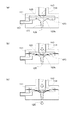
前記変形板は、前記圧電素子に押圧されることによって前記加圧室の開口部分を閉鎖し、該開口部分を閉鎖した状態で更に押圧されることによって、該加圧室内の流体を加圧する部材である
ことを特徴とする。
A.装置構成:
B.流体噴射装置の動作:
C.変形例:
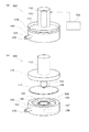
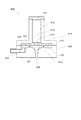
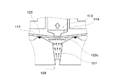
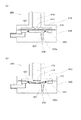
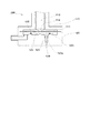
図1は、本実施例の流体噴射装置100の大まかな構造を示した説明図である。図1(a)には流体噴射装置100の外観図が示されており、図1(b)には分解組立図が示されている。図1(a)に示されるように流体噴射装置100は、金属製の第1ケース110や、同じく金属製の第2ケース120などから構成されている。詳細には後述するが、第1ケース110と第2ケース120とは、薄い円板形状のダイアフラム111を挟み込んだ状態で互いに堅固に取り付けられており、ダイアフラム111の下面側(第2ケース120側)には、後述する流体室が設けられている。本実施例ではダイアフラム111が、本発明における「変形板」に対応する。第2ケース120の側面には入口ニップル121が立設されており、入口ニップル121内には流体室に連通する入口通路122が設けられている。また、第1ケース110の上面側には、円柱状のケース部112が立設されており、ケース部112内には積層型の圧電素子113が収納されている。制御部150は、圧電素子113に対して駆動信号を出力することによって、流体噴射装置100の動作を制御する。
以上のような構造を有する本実施例の流体噴射装置100は、粘度の高い流体であってもノズル126から噴射することが可能である。以下、この点について詳しく説明する。
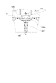
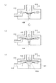
上述した実施例では、加圧室123cが、ダイアフラム111の側から見て末狭まり形状に形成されているものとして説明した。しかし、加圧室123cは必ずしも末狭まり形状でなくても構わない。また、出口通路127は、円形の加圧室123cの中心位置に開口しているものとして説明した。しかし、出口通路127が開口する位置は加圧室123cの中心位置である必要はない。以下では、このような変形例の流体噴射装置200について説明する。尚、変形例では、上述した実施例と同一の部分については同じ番号を符番することとして、詳細な説明は省略する。
112…ケース部、 113…圧電素子、 114…端板、
115…蓋板、 120…第2ケース、 121…入口ニップル、
122…入口通路、 123…凹部、 123c…加圧室、
124…凸部、 125…オーリング、 126…ノズル、
127…出口通路、 128…凸部、 150…制御部、
200…流体噴射装置
Claims (4)
- 流体を加圧することによって該流体をノズルから噴射する流体噴射装置であって、
前記流体が供給される流体室と、
前記流体室内に配置され、頂部にオーリングが設けられた円環状の凸部と、
前記凸部の内側に設けられ、前記オーリングの部分で前記流体室に開口し、前記ノズルが接続された加圧室と、
前記流体室の一部を構成し、前記加圧室の開口部分である前記オーリングの部分と向かい合わせの位置に設けられた変形板と、
前記変形板の背面側から、前記加圧室の開口部分よりも内側に対応する位置を押圧して、該変形板を変形させる圧電素子と、を備え、
前記変形板は、
前記圧電素子に押圧されることによって前記オーリングに接触し、前記加圧室の開口部分を閉鎖し、
該開口部分を閉鎖した状態で更に押圧されることによって、該加圧室内の流体を加圧する部材である
ことを特徴とする流体噴射装置。 - 請求項1に記載の流体噴射装置であって、
前記加圧室には、前記変形板の変形を規制する規制部が設けられており、
前記規制部は、前記加圧室の内壁面または前記加圧室に設けられた凸部である、
ことを特徴とする流体噴射装置。 - 請求項1または請求項2に記載の流体噴射装置であって、
前記加圧室は、前記凸部から前記ノズルに向けて末狭まり形状に形成されている、
ことを特徴とする流体噴射装置。 - 請求項3に記載の流体噴射装置であって、
前記ノズルと前記加圧室との間に設けられたノズル通路を有し、
前記ノズル通路は、前記加圧室から前記ノズルに向かって末狭まり形状に形成されている、
ことを特徴とする流体噴射装置。
Priority Applications (1)
| Application Number | Priority Date | Filing Date | Title |
|---|---|---|---|
| JP2011158732A JP5776399B2 (ja) | 2011-07-20 | 2011-07-20 | 流体噴射装置 |
Applications Claiming Priority (1)
| Application Number | Priority Date | Filing Date | Title |
|---|---|---|---|
| JP2011158732A JP5776399B2 (ja) | 2011-07-20 | 2011-07-20 | 流体噴射装置 |
Publications (2)
| Publication Number | Publication Date |
|---|---|
| JP2013022501A JP2013022501A (ja) | 2013-02-04 |
| JP5776399B2 true JP5776399B2 (ja) | 2015-09-09 |
Family
ID=47781458
Family Applications (1)
| Application Number | Title | Priority Date | Filing Date |
|---|---|---|---|
| JP2011158732A Active JP5776399B2 (ja) | 2011-07-20 | 2011-07-20 | 流体噴射装置 |
Country Status (1)
| Country | Link |
|---|---|
| JP (1) | JP5776399B2 (ja) |
Families Citing this family (2)
| Publication number | Priority date | Publication date | Assignee | Title |
|---|---|---|---|---|
| JP6673668B2 (ja) * | 2015-10-30 | 2020-03-25 | Aiメカテック株式会社 | ノズル機構、当該ノズル機構を用いるペースト塗布装置、及び、ペースト塗布方法 |
| JP6925058B2 (ja) * | 2015-10-30 | 2021-08-25 | Aiメカテック株式会社 | ノズル機構、当該ノズル機構を用いるペースト塗布装置、及び、ペースト塗布方法 |
Family Cites Families (4)
| Publication number | Priority date | Publication date | Assignee | Title |
|---|---|---|---|---|
| JP4266788B2 (ja) * | 2003-11-21 | 2009-05-20 | セイコーエプソン株式会社 | 流体噴射装置 |
| US7597417B2 (en) * | 2004-03-08 | 2009-10-06 | Fujifilm Corporation | Discharge determination device and method |
| JP4899656B2 (ja) * | 2006-06-19 | 2012-03-21 | セイコーエプソン株式会社 | 液体噴射装置及び液体収容容器 |
| JP2008195001A (ja) * | 2007-02-15 | 2008-08-28 | Mimaki Engineering Co Ltd | ノズルヘッド及び液体吐出装置 |
-
2011
- 2011-07-20 JP JP2011158732A patent/JP5776399B2/ja active Active
Also Published As
| Publication number | Publication date |
|---|---|
| JP2013022501A (ja) | 2013-02-04 |
Similar Documents
| Publication | Publication Date | Title |
|---|---|---|
| US8757511B2 (en) | Viscous non-contact jetting method and apparatus | |
| JP5599023B2 (ja) | 吐出装置 | |
| JP3463929B2 (ja) | 体積センサのない微量分注デバイス、分注デバイス配列、および微量分注デバイスの使用用途 | |
| JP5320462B2 (ja) | 空圧ディスペンサ | |
| JP5540760B2 (ja) | 液体噴射装置 | |
| JP6793397B2 (ja) | シール構造および該シール構造を備える装置 | |
| KR101126722B1 (ko) | 액체 토출장치 | |
| JP5776399B2 (ja) | 流体噴射装置 | |
| JP5802347B1 (ja) | 微量液体滴下方法および微量液体ディスペンサ | |
| JP2013212452A (ja) | 流体噴射装置 | |
| JP2022510639A (ja) | 投与システム、および投与システムを制御する方法 | |
| CN109789702B (zh) | 液体排出装置、具有液体排出装置的检查装置以及具有液体排出装置的细胞培养装置 | |
| CN101855088B (zh) | 液滴分断装置 | |
| JP2013139745A (ja) | 粘性非接触噴射方法および装置 | |
| JP5811655B2 (ja) | 流体噴射装置 | |
| JP5524637B2 (ja) | 微小液滴吐出装置 | |
| US20110250403A1 (en) | Bonding on silicon substrate | |
| JP2018020291A (ja) | 液体供給装置 | |
| CN106956510B (zh) | 压力调节装置以及液体喷射装置 | |
| US8297743B2 (en) | Droplet ejection head and method of manufacturing coated body | |
| US6558136B1 (en) | Micropump underpressure control device | |
| KR20100085703A (ko) | 잉크젯 헤드 | |
| JP2017127838A (ja) | 液体吐出装置 | |
| JP2017127839A (ja) | 液体吐出用の吐出ノズル | |
| CN114945429B (zh) | 具有柔性喷嘴的喷射装置 |
Legal Events
| Date | Code | Title | Description |
|---|---|---|---|
| A621 | Written request for application examination |
Free format text: JAPANESE INTERMEDIATE CODE: A621 Effective date: 20140613 |
|
| RD04 | Notification of resignation of power of attorney |
Free format text: JAPANESE INTERMEDIATE CODE: A7424 Effective date: 20150107 |
|
| A131 | Notification of reasons for refusal |
Free format text: JAPANESE INTERMEDIATE CODE: A131 Effective date: 20150331 |
|
| A521 | Written amendment |
Free format text: JAPANESE INTERMEDIATE CODE: A523 Effective date: 20150525 |
|
| TRDD | Decision of grant or rejection written | ||
| A01 | Written decision to grant a patent or to grant a registration (utility model) |
Free format text: JAPANESE INTERMEDIATE CODE: A01 Effective date: 20150609 |
|
| A61 | First payment of annual fees (during grant procedure) |
Free format text: JAPANESE INTERMEDIATE CODE: A61 Effective date: 20150622 |
|
| R150 | Certificate of patent (=grant) or registration of utility model |
Ref document number: 5776399 Country of ref document: JP Free format text: JAPANESE INTERMEDIATE CODE: R150 |
|
| S531 | Written request for registration of change of domicile |
Free format text: JAPANESE INTERMEDIATE CODE: R313531 |
|
| R350 | Written notification of registration of transfer |
Free format text: JAPANESE INTERMEDIATE CODE: R350 |