JP5776399B2 - Fluid ejection device - Google Patents
Fluid ejection device Download PDFInfo
- Publication number
- JP5776399B2 JP5776399B2 JP2011158732A JP2011158732A JP5776399B2 JP 5776399 B2 JP5776399 B2 JP 5776399B2 JP 2011158732 A JP2011158732 A JP 2011158732A JP 2011158732 A JP2011158732 A JP 2011158732A JP 5776399 B2 JP5776399 B2 JP 5776399B2
- Authority
- JP
- Japan
- Prior art keywords
- fluid
- pressurizing chamber
- nozzle
- diaphragm
- chamber
- Prior art date
- Legal status (The legal status is an assumption and is not a legal conclusion. Google has not performed a legal analysis and makes no representation as to the accuracy of the status listed.)
- Active
Links
- 239000012530 fluid Substances 0.000 title claims description 206
- 238000003825 pressing Methods 0.000 claims description 2
- 238000002347 injection Methods 0.000 description 18
- 239000007924 injection Substances 0.000 description 18
- 230000004048 modification Effects 0.000 description 9
- 238000012986 modification Methods 0.000 description 9
- 238000004519 manufacturing process Methods 0.000 description 5
- 238000010586 diagram Methods 0.000 description 4
- 239000011325 microbead Substances 0.000 description 4
- 210000002445 nipple Anatomy 0.000 description 4
- 238000013459 approach Methods 0.000 description 3
- 239000003814 drug Substances 0.000 description 3
- 229940079593 drug Drugs 0.000 description 3
- 239000007788 liquid Substances 0.000 description 3
- 238000000034 method Methods 0.000 description 3
- 230000007423 decrease Effects 0.000 description 2
- 230000003247 decreasing effect Effects 0.000 description 2
- 238000006073 displacement reaction Methods 0.000 description 2
- 239000000463 material Substances 0.000 description 2
- 239000002184 metal Substances 0.000 description 2
- 230000002093 peripheral effect Effects 0.000 description 2
- 230000001105 regulatory effect Effects 0.000 description 2
- 230000009466 transformation Effects 0.000 description 2
- 206010013642 Drooling Diseases 0.000 description 1
- 229920001875 Ebonite Polymers 0.000 description 1
- 208000008630 Sialorrhea Diseases 0.000 description 1
- 238000005452 bending Methods 0.000 description 1
- 239000006185 dispersion Substances 0.000 description 1
- 238000009826 distribution Methods 0.000 description 1
- 230000000694 effects Effects 0.000 description 1
- 238000005516 engineering process Methods 0.000 description 1
- 230000007721 medicinal effect Effects 0.000 description 1
- 239000007769 metal material Substances 0.000 description 1
- 239000002245 particle Substances 0.000 description 1
- 230000000149 penetrating effect Effects 0.000 description 1
- 238000007639 printing Methods 0.000 description 1
- 229910001220 stainless steel Inorganic materials 0.000 description 1
- 239000010935 stainless steel Substances 0.000 description 1
Images

Landscapes
- Coating Apparatus (AREA)
- Particle Formation And Scattering Control In Inkjet Printers (AREA)
Description
本発明は、流体室内の流体を加圧してノズルから噴射する技術に関する。 The present invention relates to a technique for pressurizing a fluid in a fluid chamber and ejecting the fluid from a nozzle.
インクジェットプリンターに代表される流体噴射装置が知られている。この流体噴射装置は、流体を噴射するためのノズルを備えており、微細な量の流体を高い精度で且つ繰り返して噴射することが可能である。そこで今日では、インク以外の様々流体を噴射することによって、画像の印刷以外の様々な分野への応用が試みられている。 A fluid ejecting apparatus represented by an ink jet printer is known. This fluid ejecting apparatus includes a nozzle for ejecting a fluid, and can eject a minute amount of fluid repeatedly with high accuracy. Therefore, today, various fluids other than ink have been tried to be applied to various fields other than image printing.
例えば、医療向けの分野としては、流体噴射装置を用いてマイクロビーズ状のゲル(マイクロビーズゲル)を作成する技術が提案されている。この提案の技術によれば、接触するとゲル状に固まる2種類の液体の一方を、流体噴射装置を用いて他方の液体中に噴射することによって、粒径の揃ったマイクロビーズゲルを作成する(特許文献1、特許文献2)。流体噴射装置で噴射する側の液体の薬剤成分を混ぜておけば、薬剤成分が封入されたマイクロビーズゲルを生成することができる。そして、得られたマイクロビーズゲルを人体に投与すれば、体内での薬剤成分の分布を制御することが可能となって、副作用を抑えながら大きな薬効を得ることができるものと期待されている。 For example, in the medical field, a technique for creating a microbeaded gel (microbead gel) using a fluid ejecting apparatus has been proposed. According to this proposed technique, a microbead gel having a uniform particle size is created by ejecting one of two types of liquid that solidifies into a gel when contacted into the other liquid using a fluid ejecting apparatus ( Patent Document 1 and Patent Document 2). If the liquid drug component to be ejected by the fluid ejecting apparatus is mixed, a microbead gel in which the drug component is encapsulated can be generated. If the obtained microbead gel is administered to the human body, it is expected that the distribution of the drug component in the body can be controlled, and a large medicinal effect can be obtained while suppressing side effects.
しかし、流体噴射装置はノズルの内径が小さいので、粘度の高い流体を噴射しようとすると大きな力が必要となり、流体噴射装置が大型化してしまうという問題があった。 However, since the fluid ejecting apparatus has a small inner diameter of the nozzle, a large force is required to eject a fluid having a high viscosity, and the fluid ejecting apparatus is increased in size.
この発明は、従来の技術が有する上述した課題の少なくとも一部を解決するためになされたものであり、粘度の高い流体であっても、流体噴射装置を大型化させることなく噴射することが可能な技術の提供を目的とする。 The present invention has been made to solve at least a part of the above-described problems of the prior art, and even a fluid having a high viscosity can be ejected without increasing the size of the fluid ejecting apparatus. Aims to provide new technology.
上述した課題の少なくとも一部を解決するために、本発明の流体噴射装置は次の構成を採用した。すなわち、
流体を加圧することによって該流体をノズルから噴射する流体噴射装置であって、
前記流体が供給される流体室と、
凹形状に形成されて前記流体室に開口し、前記ノズルが接続された加圧室と、
前記流体室の一部を構成し、前記加圧室の開口部分と向かい合わせの位置に設けられた変形板と、
前記変形板の背面側から、前記加圧室の開口部分よりも内側に対応する位置を押圧して、該変形板を変形させる圧電素子と、
を備え、
前記変形板は、前記圧電素子に押圧されることによって前記加圧室の開口部分を閉鎖し、該開口部分を閉鎖した状態で更に押圧されることによって、該加圧室内の流体を加圧する部材である
ことを特徴とする。
In order to solve at least a part of the problems described above, the fluid ejecting apparatus of the present invention employs the following configuration. That is,
A fluid ejecting apparatus that ejects fluid from a nozzle by pressurizing the fluid,
A fluid chamber to which the fluid is supplied;
A pressurizing chamber formed in a concave shape and opening into the fluid chamber, to which the nozzle is connected;
A part of the fluid chamber, and a deformation plate provided at a position facing the opening of the pressurizing chamber;
A piezoelectric element for pressing the position corresponding to the inside of the opening portion of the pressurizing chamber from the back side of the deformation plate, and deforming the deformation plate;
With
The deformation plate closes the opening portion of the pressurizing chamber by being pressed by the piezoelectric element, and further presses the fluid in the pressurizing chamber by being further pressed while the opening portion is closed. It is characterized by.
このような構成を有する本発明の流体噴射装置においては、圧電素子を用いて変形板を変形させると、加圧室の開口部分が変形板によって閉鎖され、その状態から更に変形板を変形させることによって、加圧室内の流体を加圧する。 In the fluid ejecting apparatus of the present invention having such a configuration, when the deformation plate is deformed using the piezoelectric element, the opening portion of the pressurizing chamber is closed by the deformation plate, and the deformation plate is further deformed from the state. To pressurize the fluid in the pressurizing chamber.
こうすれば、加圧室の開口部分を閉鎖した後は、変形板を変形させたときに加圧室内の流体が流体室に逃げなくなる。このため、加圧室内の流体を効率よく加圧することができるので、大型の圧電素子を用いるなど、流体噴射装置を大型化しなくても、粘度の高い流体を加圧してノズルから噴射させることが可能となる。加えて、流体の噴射終了後は、加圧室の開口部分を閉鎖したままとなっているので、流体室側から加圧室内に流体が供給されることがない。このため、流体の噴射終了後にノズルから流体が漏れ出す事態を回避することができる。更に、変形板の変形が元に戻る際には、初めのうちは加圧室の開口部分を閉鎖したまま加圧室の容積が増加するので、ノズル付近の流体が加圧室の方向に引き戻される。この点からも、流体の噴射終了後にノズルから流体が漏れ出す事態を回避することができる。 In this way, after closing the opening of the pressurizing chamber, the fluid in the pressurizing chamber does not escape to the fluid chamber when the deformation plate is deformed. For this reason, since the fluid in the pressurizing chamber can be pressurized efficiently, a fluid having a high viscosity can be pressurized and ejected from the nozzle without using a large fluid ejecting apparatus such as using a large piezoelectric element. It becomes possible. In addition, since the opening of the pressurizing chamber remains closed after the completion of the fluid ejection, no fluid is supplied from the fluid chamber side to the pressurizing chamber. For this reason, it is possible to avoid a situation in which the fluid leaks from the nozzle after the completion of the fluid ejection. Furthermore, when the deformation plate is restored, the volume of the pressurizing chamber increases while the opening of the pressurizing chamber is initially closed, so that the fluid near the nozzle is pulled back toward the pressurizing chamber. It is. Also from this point, it is possible to avoid a situation in which the fluid leaks from the nozzle after completion of the fluid injection.
また、上述した本発明の流体噴射装置においては、変形板の変形を規制する規制部を加圧室に設けておき、変形板は、加圧室の開口部分を閉鎖した後は規制部に当接するまで変形するようにしてもよい。尚、規制部は、加圧室の開口部分を閉鎖した後の変形板に当接して、変形板の変形を規制するものであれば良く、従って、加圧室の内壁面のうちの変形板に当接する部分とすることもできる。 In the fluid ejecting apparatus of the present invention described above, a restricting portion for restricting deformation of the deformable plate is provided in the pressurizing chamber, and the deformable plate contacts the restricting portion after the opening portion of the pressurizing chamber is closed. You may make it deform | transform until it touches. The restricting portion only needs to be in contact with the deformed plate after closing the opening portion of the pressurizing chamber and restrict the deformation of the deformable plate, and therefore, the deformable plate on the inner wall surface of the pressurizing chamber. It can also be set as the part which contacts.
こうすれば、流体の噴射量は、加圧室の開口部分を閉鎖してから規制部に当接するまでの変形板の変形量によって決定される。そして、変形板が、加圧室の開口部分を閉鎖してから規制部に当接するまでの変形量のばらつきは、加圧室の製造精度を上げることによって、十分に小さくすることができる。その結果、高い精度の噴射量で流体を噴射することが可能となる。 In this way, the fluid ejection amount is determined by the deformation amount of the deformation plate from the closing of the opening portion of the pressurizing chamber to the contact with the restricting portion. And the dispersion | variation in the deformation | transformation amount after a deformation | transformation board closes the opening part of a pressurization chamber until it contact | abuts to a control part can be made small enough by raising the manufacture precision of a pressurization chamber. As a result, the fluid can be ejected with a highly accurate ejection amount.
また、上述した本発明の流体噴射装置においては、加圧室を、変形板の側から見て末狭まり形状に形成し、末狭まり形状の末端位置にノズルを接続するようにしても良い。 In the above-described fluid ejecting apparatus of the present invention, the pressurizing chamber may be formed in a narrowed shape when viewed from the deformation plate side, and the nozzle may be connected to the end position of the narrowed shape.
詳細なメカニズムについては後述するが、加圧室を、変形板の側から見て末狭まり形状に形成しておけば、変形板を変形させて加圧室内の流体を加圧したときに、加圧室内で流体が加速される。従って、末狭まり形状の末端位置にノズルを接続しておけば、ノズルから勢いよく流体を噴射することができる。また、流体の噴射後は、変形板の変形を戻したことによって生じる負圧が、ノズル付近の流体に効率よく伝わって、流体が加圧室の方向に引き戻される。このため、噴射終了後にノズルから流体が漏れ出す事態を、より確実に回避することが可能となる。 Although the detailed mechanism will be described later, if the pressurizing chamber is formed in a narrowed shape when viewed from the side of the deforming plate, it is added when the fluid in the pressurizing chamber is pressurized by deforming the deforming plate. The fluid is accelerated in the pressure chamber. Therefore, if the nozzle is connected to the end position of the narrow shape, the fluid can be ejected vigorously from the nozzle. Further, after the fluid is ejected, the negative pressure generated by returning the deformation of the deformation plate is efficiently transmitted to the fluid near the nozzle, and the fluid is pulled back toward the pressurizing chamber. For this reason, it is possible to more reliably avoid a situation where fluid leaks from the nozzle after the end of injection.
また、末狭まり形状の加圧室を備えた本発明の流体噴射装置においては、加圧室からノズルまでのノズル通路も、ノズルに向かって末狭まり形状に形成してもよい。 Further, in the fluid ejecting apparatus of the present invention provided with the narrowed pressurizing chamber, the nozzle passage from the pressurizing chamber to the nozzle may be formed in a narrowed shape toward the nozzle.
こうすれば、流体を噴射する際には、ノズル通路においても流体を加速することができるので、ノズルから勢いよく流体を噴射することができる。また、流体の噴射終了後は、加圧室内で生じた負圧をノズル付近の流体に効率よく伝えることができるので、噴射終了後にノズルから流体が漏れ出す事態を、より一層確実に回避することが可能となる。 In this way, when the fluid is ejected, the fluid can be accelerated also in the nozzle passage, so that the fluid can be ejected vigorously from the nozzle. In addition, since the negative pressure generated in the pressurizing chamber can be efficiently transmitted to the fluid near the nozzle after the completion of the fluid injection, the situation where the fluid leaks from the nozzle after the completion of the injection can be more reliably avoided. Is possible.
以下では、上述した本願発明の内容を明確にするために、次のような順序に従って実施例を説明する。
A.装置構成:
B.流体噴射装置の動作:
C.変形例:
Hereinafter, in order to clarify the contents of the present invention described above, examples will be described in the following order.
A. Device configuration:
B. Operation of fluid ejection device:
C. Variation:
A.装置構成 :
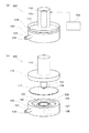
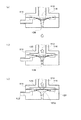
図1は、本実施例の流体噴射装置100の大まかな構造を示した説明図である。図1(a)には流体噴射装置100の外観図が示されており、図1(b)には分解組立図が示されている。図1(a)に示されるように流体噴射装置100は、金属製の第1ケース110や、同じく金属製の第2ケース120などから構成されている。詳細には後述するが、第1ケース110と第2ケース120とは、薄い円板形状のダイアフラム111を挟み込んだ状態で互いに堅固に取り付けられており、ダイアフラム111の下面側(第2ケース120側)には、後述する流体室が設けられている。本実施例ではダイアフラム111が、本発明における「変形板」に対応する。第2ケース120の側面には入口ニップル121が立設されており、入口ニップル121内には流体室に連通する入口通路122が設けられている。また、第1ケース110の上面側には、円柱状のケース部112が立設されており、ケース部112内には積層型の圧電素子113が収納されている。制御部150は、圧電素子113に対して駆動信号を出力することによって、流体噴射装置100の動作を制御する。
A. Device configuration :
FIG. 1 is an explanatory diagram showing a rough structure of a fluid ejecting
図1(b)に示されるように、第2ケース120の上面側には、円形の浅い凹部123が形成されており、凹部123内には、凹部123と同心円状に土手状の凸部124が形成され、凸部124の頂部にはオーリング125が取り付けられている。凸部124の高さは、オーリング125が凹部123から突出しない高さに設定されている。また、凸部124の中心位置には、第2ケース120の底面側まで貫通する出口通路127が形成されており、出口通路127が底面側に開口した部分にノズル126が形成されている。更に、円環状の凸部124の外側には、入口ニップル121内に形成された入口通路122が開口している。
As shown in FIG. 1B, a circular shallow
ダイアフラム111は、凹部123よりも大きな外径に形成されている。このためダイアフラム111を第2ケース120の上面に載せると、凹部123全体がダイアフラム111で覆われた状態となる。またダイアフラム111は、ステンレスなどの弾性に富んだ金属材料によって形成されている。ダイアフラム111の上から第1ケース110を載せると、ダイアフラム111の外周部分が第1ケース110と第2ケース120との間で挟み込まれて固定される。また、このとき、ケース部112内の圧電素子113は、端板114を介してダイアフラム111に当接した状態となる。
The
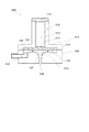
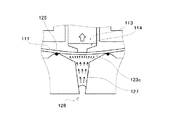
図2は、流体噴射装置100の詳細な構造を示す断面図である。図1(b)を用いて前述したように、ダイアフラム111は、外周部分が第1ケース110と第2ケース120とによって挟み込まれた状態で固定されている。また、第2ケース120に設けられた凹部123は、ダイアフラム111によって覆われている。本実施例では、第2ケース120の凹部123とダイアフラム111とによって囲まれた空間が流体室となる。また、凹部123内には円環状の凸部124が設けられており、凸部124の上部にはオーリング125が設けられている。そして、オーリング125の内側には、下方に向けて漏斗形状に形成された加圧室123cが設けられ、漏斗形状の先端部分に出口通路127を介してノズル126が接続されている。また、出口通路127も、ノズル126に向かって少しずつ内径が小さくなる末狭まり形状に形成されている。尚、加圧室123cは、オーリング125の部分で流体室(凹部123)に開口していることから、本実施例では、オーリング125の部分が本発明における「加圧室の開口部分」に対応する。また、出口通路127が本発明における「ノズル通路」に対応する。
FIG. 2 is a cross-sectional view showing a detailed structure of the
通常の状態(ダイアフラム111が変形していない状態)では、オーリング125とダイアフラム111との間には隙間が形成されている。このため、入口通路122から流体を供給すると、流体は、凹部123、加圧室123c、および出口通路127に満たされる。
In a normal state (a state where the
一方、第1ケース110のケース部112は上端側が開口されており、ここに略円板形状の蓋板115が、ネジ止めなどによって堅固に取り付けられる。圧電素子113は、上端側が蓋板115に接着された状態でケース部112内に収納される。また、圧電素子113の下端側には端板114が接着されており、圧電素子113に駆動信号が印加されていない状態(初期状態)では、端板114がダイアフラム111の上面側に接触した状態となっている。尚、初期状態は、圧電素子113に電圧が印加されていない状態であってもよいし、初期電圧は印加されているが駆動信号は印加されていない状態であってもよい。また、圧電素子113が端板114を介してダイアフラム111を押圧する位置は、ダイアフラム111の向かい側に設けられたオーリング125の内側に対応する位置となっている。
On the other hand, the
B.流体噴射装置の動作 :
以上のような構造を有する本実施例の流体噴射装置100は、粘度の高い流体であってもノズル126から噴射することが可能である。以下、この点について詳しく説明する。
B. Operation of fluid ejection device:
The
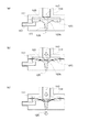
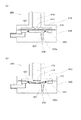
図3は、本実施例の流体噴射装置100が流体を噴射する動作を示した説明図である。図3(a)には、圧電素子113に駆動信号を印加する前の状態(初期状態)が示されている。この状態では、オーリング125とダイアフラム111との間には隙間が形成されている。このため、凹部123(流体室)および加圧室123cは、入口通路122から供給された流体によって満たされた状態となる。尚、出口通路127も流体で満たされるが、流体が表面張力によってノズル126に界面を形成するため、ノズル126から流体が流出することはない。
FIG. 3 is an explanatory diagram showing an operation of ejecting fluid by the
続いて、圧電素子113に駆動信号を印加すると、圧電素子113が伸張してダイアフラム111を下方に撓ませる。その結果、図3(b)に示すように、ダイアフラム111がオーリング125に当接して、加圧室123cの開口部分を閉鎖した状態となる。この状態から、圧電素子113に印加する駆動信号の電圧を更に増加させて圧電素子113を更に伸張させると、オーリング125に当接した部分よりも内側のダイアフラム111が下方に撓むように変形する。ダイアフラム111がオーリング125に当接しているので、圧電素子113が発生する力は、ほとんど全てが加圧室123c内の流体を加圧するために使われる。このため、圧電素子113を大型化しなくても、たいへんに高い圧力で加圧室123cの流体を加圧することができる。その結果、粘度の高い流体であっても、図3(c)に示すように、ノズル126から噴射することが可能となる。
Subsequently, when a drive signal is applied to the
尚、本実施例では、オーリング125が硬質ゴムなどの比較的硬い材料で形成されているため、ダイアフラム111がオーリング125に当接した後は、オーリング125に当接した部分よりも内側のダイアフラム111が変形するものとして説明した。しかし、オーリング125を柔らかいゴム材料で形成してもよい。こうすれば、ダイアフラム111がオーリング125に当接した後も、オーリング125を変形させることによってダイアフラム111全体が変形する。このため、ダイアフラム111の大きな変位を確保することが容易となり、その結果、大きな変位を確保するためにダイアフラム111を無理に変形させて、局所的に大きな応力が発生する事態を回避することができる。
In this embodiment, since the O-
また、本実施例の流体噴射装置100では、図3(c)に示すようにダイアフラム111は加圧室123cの内壁面に当接するまで変形する。このため、以下の理由から、噴射量の精度を向上させることが可能となる。先ず、ダイアフラム111がオーリング125に当接するまでは、加圧室123cから凹部123に流体が逃げてしまうので、加圧室123c内の流体をあまり加圧することができない。このため、ダイアフラム111がオーリング125に当接するまでは、ダイアフラム111が撓んでもノズル126からの流体が噴射することはない。一方、ダイアフラム111がオーリング125に当接した後は加圧室123c内の流体を効率よく加圧することが可能となる。従って、ダイアフラム111がオーリング125に当接してから加圧室123cの内壁面に当接するまでの撓み量が、ノズル126からの流体の噴射量を決定する。
In the
ここで、この撓み量(ダイアフラム111がオーリング125に当接してから加圧室123cの内壁面に当接するまでの撓み量)のばらつきは、凸部124や加圧室123cの製造精度を上げることによって、かなりのレベルまで小さくすることができる。例えば図3(c)に示した例では、ダイアフラム111が、加圧室123cの斜面になった部分に倣う形状に撓んでいる。従って、加圧室123cの開口部分(オーリング125が設けられた部分)や、その内側の加圧室123cの斜面の部分の製造精度が、流体の噴射量を決定する。
Here, this variation in the amount of deflection (the amount of deflection from when the
仮に、ダイアフラム111を加圧室123cの斜面に当接させないものとすると、ダイアフラム111の変形量は圧電素子113の変形量によって決定される。ここで圧電素子113には個体差が存在しており、同じ電圧を加えた場合でも、圧電素子113毎に変形量にはばらつきが生じる。この圧電素子113の個体差に比べれば、加圧室123cの製造精度は非常に高い精度を実現することができる。このため、本実施例の流体噴射装置100では、非常に精度の高い噴射量で、流体を噴射することが可能となる。
If the
尚、本実施例では、加圧室123cの斜めになった内壁面に当接するまでダイアフラム111が変形する。従って、加圧室123cの内壁面が本発明における「規制部」に対応する。もっとも、加圧室123cの内壁面に凸部を設けて、この凸部に当接するまでダイアフラム111が変形するようにしても良い。この場合は、この凸部が本発明における「規制部」に対応する。
In this embodiment, the
また、加圧室123cは、ノズル126に向かって末狭まりの漏斗形状に形成されている。更に、加圧室123cとノズル126とを接続する出口通路127も、ノズル126に近付くほど内径が小さくなる末狭まり形状に形成されている。このため、粘度の高い流体であっても、以下の理由から、勢いよくノズル126から噴射することが可能となる。
The pressurizing
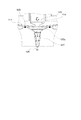
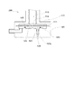
図4は、本実施例の流体噴射装置100が粘度の高い流体であってもノズル126から勢いよく噴射可能な理由を示した説明図である。図4では、ダイアフラム111がオーリング125に当接した状態で、更に撓むことによって加圧室123c内の流体を加圧している様子が示されている。ダイアフラム111がオーリング125に当接した状態で下方に少しだけ撓むと、ダイアフラム111に接していた流体が下方に押し出される。ここで加圧室123cは、ダイアフラム111の側から見て末狭まり形状となっているので、押し出された流体は、ダイアフラム111が押し出した速度よりも加速する。そして、加速した流体は、その下の流体を下方に押し出して、押し出された流体が、加圧室123cの末狭まり形状によって加速される。その流体が更にその下の流体を下方に押し出して、押し出された流体が加速される。
FIG. 4 is an explanatory diagram illustrating the reason why the
このように、ダイアフラム111の側から見て加圧室123cが末狭まり形状となっているので、出口通路127の入口付近の流体は、ダイアフラム111が流体を押し出した速度以上に加速して出口通路127に流入する。そして、出口通路127もノズル126に向かって末狭まり形状になっている。このため、出口通路127の中でもノズル126に近付くにつれて流体の動きが加速されて、最終的には流体がノズル126から勢いよく噴射される。図4では、ダイアフラム111で押し出された流体の動きが、加圧室123cおよび出口通路127の中をノズル126に向かって進むに従って加速される様子が、破線の矢印によって表されている。
Thus, since the pressurizing
また、図4に示されるように、加圧室123cとノズル126との間は出口通路127によって直結されており、加圧室123cからノズル126までの流路抵抗はたいへんに小さくなっている。このため、ノズル126から噴射されるまでの間に抵抗によって流れが減衰することが抑制されるので、粘度の高い流体であっても、勢いよくノズル126から噴射することが可能となる。
Further, as shown in FIG. 4, the pressurizing
図5は、本実施例の流体噴射装置100が流体を噴射した後の動作を示した説明図である。図5(a)には、ノズル126から流体を噴射した直後の状態が示されている。この状態から、圧電素子113に印加した駆動信号の電圧を低下させると、伸張していた圧電素子113が収縮し、それに伴ってダイアフラム111が元の形状に戻ろうとする。ここで、図3を用いて前述したように流体を噴射する際には、ダイアフラム111を撓ませてオーリング125に当接させ、更にその状態からダイアフラム111を撓ませて、加圧室123c内の流体を加圧している。従って、流体を噴射した後に圧電素子113が少し収縮した程度では、ダイアフラム111がオーリング125から離れることはない。このため、加圧室123cは、凹部123から流体の供給を受けることができないまま容積が増加することになり、その結果、加圧室123cの容積が増加した分だけ、出口通路127内の流体が引き戻される。
FIG. 5 is an explanatory view showing an operation after the
図5(b)には、流体を噴射した後に駆動信号の電圧を低下させた後の状態が示されている。図5(a)に示した駆動信号の電圧を低下させる前の状態と比較すると、電圧が低下したことによって圧電素子113が収縮し、それに伴って加圧室123cの容積が増加して、出口通路127内の流体が加圧室123cに引き込まれている。
FIG. 5B shows a state after the voltage of the drive signal is lowered after the fluid is ejected. Compared with the state before reducing the voltage of the drive signal shown in FIG. 5A, the
更に駆動信号の電圧を低下させると、やがてはダイアフラム111がオーリング125から離間して、加圧室123cと凹部123(流体室)とが連通する。図5(c)には、ダイアフラム111がオーリング125から離間した状態が示されている。この状態から更に駆動信号の電圧を低下させると、ダイアフラム111の撓みは更に小さくなり、加圧室123cの容積は更に増加する。もっとも、この状態では加圧室123cと凹部123とが連通しているので、加圧室123cの容積が増加した分の流体が凹部123から加圧室123cに供給される。
When the voltage of the drive signal is further decreased, the
尚、ダイアフラム111がオーリング125から離間して暫くの期間は、ダイアフラム111とオーリング125との間に形成される隙間は、決して大きなものではない。しかしこの隙間は、ダイアフラム111とオーリング125とが円形に接触していた部分の全周に亘って形成されて、この全周から流体が流れ込む。このため、加圧室123cの容積を急激に増加させるのでない限り、加圧室123cの容積増加分に相当する流体を供給することができる。図5(c)中には、加圧室123cに流体が供給される様子が、破線の矢印で示されている。
Note that the gap formed between the
そして、ダイアフラム111が元の形状に戻ると、ダイアフラム111とオーリング125との間には十分な大きさの隙間が形成される。このため、入口通路122から供給された流体が、凹部123(流体室)、加圧室123c、および出口通路127を満たして、図3(a)に示した初期状態に復帰する。
When the
このように、本実施例の流体噴射装置100では、ノズル126から流体を噴射した直後はダイアフラム111がオーリング125に当接しており、ダイアフラム111をオーリング125に当接させたまま、加圧室123cの容積を増加させる。このため、噴射直後に出口通路127内をノズル126に向かって流れている流体を、加圧室123cに引き戻すことができるので、噴射終了後にノズル126から漏れ出すことを回避することが可能となる。以下では、噴射終了後にノズル126から流体が漏れ出すことを、「後だれ」と称することがある。
As described above, in the
もっとも、流体の噴射後であっても、ダイアフラム111の変形を元に戻し始めるまでの間は、出口通路127内の流体を加圧室123cに引き戻す作用は生じない。しかし、ダイアフラム111の変形を元に戻し始めなくても、ダイアフラム111はオーリング125に当接しており、加圧室123cに外部から流体が供給されないので、ノズル126からの後だれは発生し難くなっている。
However, even after the fluid has been ejected, the fluid in the
更に、前述したように、加圧室123cはノズル126に向かって末狭まり形状に形成されている。更に、出口通路127もノズル126に向かって末狭まり形状に形成されている。このことは、ノズル126から勢いよく流体を噴射することに対して有効であるが、流体の噴射終了後にノズル126の後だれが発生することを回避する点からも有効である。
Further, as described above, the pressurizing
図6は、加圧室123cあるいは出口通路127をノズル126に向かって末狭まり形状とすることが、ノズル126の後だれ回避に有効な理由を示した説明図である。前述したように、噴射終了後のノズル126の後だれが回避される理由の1つは、ダイアフラム111の変形が元に戻ろうとするときに、出口通路127内の流体を加圧室123cに引き戻す力が発生するためである。この力は、元の形状に戻ろうとするダイアフラム111が、ダイアフラム111に接する流体に対して負圧を発生させることに起因する。ダイアフラム111と流体との境界に生じた負圧は、境界の下方に隣接する流体を引き込むので、その流体があった箇所に負圧を発生させ、その負圧が、更に下方に隣接する流体を引き込む。このとき、加圧室123cが下方に末狭まりの漏斗形状に形成されていると、下方に行くほど断面積が小さくなるから、大きな面積で負圧を受けて、その直ぐ下方の少しだけ小さな面積の流体を引き込むことになる。このため下方の流体は、上方の流体が引き込まれた力よりも強い力で引き込まれる。
FIG. 6 is an explanatory diagram showing the reason why it is effective for the
こうして強い力で流体を引き込む結果、流体があった箇所にはより大きな負圧が生じる。その大きな負圧は更にその下方の流体を引き込むが、下方では加圧室123cの断面積が更に小さくなるので、下方の流体は更に強い力で引き込まれることになる。このように、加圧室123cを下方に末狭まりの形状に形成しておけば、下方に行くほど強い力で流体を引き込むことができる。また、出口通路127も、ノズル126に向かって末狭まり形状に形成されているので、出口通路127の中でも同様なことが生じて、ノズル126に近付くほど強い力で、流体が加圧室123c側に引き戻される。このため、流体の噴射終了後にノズル126で後だれが発生することを回避することが可能となる。図6中には、元の形状に戻ろうとするダイアフラム111によって生じた力が、次第に強い力に変換されながら加圧室123cおよび出口通路127内を下方に伝わる様子が、破線の矢印によって模式的に表されている。
As a result of drawing the fluid with such a strong force, a larger negative pressure is generated at the place where the fluid was present. The large negative pressure further draws the fluid below, but since the cross-sectional area of the pressurizing
参考として、図7には、加圧室123cおよび出口通路127が末狭まり形状に形成されていない場合に、ダイアフラム111で生じた力が、加圧室123cおよび出口通路127内を下方に伝わる様子を例示した。図7に示した例では、ダイアフラム111から直接に力を受ける部分の面積が、加圧室123cの底部に達するまで変わらない。このため、単に負圧が伝わるだけであり、加圧室123c内でより大きな負圧に変換されることがない。
For reference, FIG. 7 shows that the force generated in the
そして、加圧室123cの底部で出口通路127が開口している部分の面積に、加圧室123c内を伝わってきた負圧を乗算した力が、出口通路127内の流体に作用する。逆に言えば、加圧室123cの底部に作用する負圧であっても、出口通路127が開口していない部分に作用する負圧は、出口通路127内の流体を引き戻すためには使われない。加えて、出口通路127内も断面積が一定なので、出口通路127内を単に負圧が伝達されるだけであり、より大きな負圧に変換されることはない。結局、ダイアフラム111が発生した負圧の一部(単純に言えば、ダイアフラム111が加圧室123cに接する部分の面積に対して、加圧室123cの底部で出口通路127が開口する部分の面積が占める割合)しか、出口通路127内の流体を引き戻すためには使われない。これに対して、図6に示したように、加圧室123cおよび出口通路127を末狭まり形状にしておけば、ダイアフラム111で発生した負圧を出口通路127内の流体に効率よく伝えることができる。その結果、噴射終了後のノズル126での後だれの発生をより一層確実に抑制することが可能となる。
A force obtained by multiplying the area of the portion where the
C.変形例 :
上述した実施例では、加圧室123cが、ダイアフラム111の側から見て末狭まり形状に形成されているものとして説明した。しかし、加圧室123cは必ずしも末狭まり形状でなくても構わない。また、出口通路127は、円形の加圧室123cの中心位置に開口しているものとして説明した。しかし、出口通路127が開口する位置は加圧室123cの中心位置である必要はない。以下では、このような変形例の流体噴射装置200について説明する。尚、変形例では、上述した実施例と同一の部分については同じ番号を符番することとして、詳細な説明は省略する。
C. Modified example:
In the above-described embodiment, the pressurizing
図8は、末狭まり形状でない加圧室123cを備えた変形例の流体噴射装置200の構造を示した断面図である。図8(a)には、ダイアフラム111が変形する前の状態が示されており、図8(b)にはダイアフラム111が変形した後の状態が示されている。図8(a)に示すように、変形例の流体噴射装置200では、加圧室123cが円形の浅い凹形状に形成されている。また、出口通路127は、加圧室123cの中心から偏心した位置に開口している。
FIG. 8 is a cross-sectional view showing the structure of a
このような変形例の流体噴射装置200においても、圧電素子113に駆動信号を印加してダイアフラム111を変形させると、ダイアフラム111がオーリング125に当接して加圧室123cを閉鎖する。更にその状態からダイアフラム111が変形することによって、加圧室123c内の流体を加圧する。ダイアフラム111が加圧室123cを閉鎖しているので、加圧室123c内の流体が凹部123(流体室)に逃げることがなく、加圧室123cの流体を効率よく加圧することができる。その結果、たとえ粘度の高い流体であっても、ノズル126から噴射することが可能となる。
Also in the
また、図8(b)に示されるように、ダイアフラム111は加圧室123cの底部に当接するまで変形する。すなわち、オーリング125に当接してから加圧室123cの底部に当接するまでのダイアフラム111の変形量が、流体の噴射量を決定する。従って、オーリング125が設けられた部分や、加圧室123cの底部の製造精度を上げることにより、非常に精度の高い噴射量で流体を噴射することが可能となる。尚、図8に示した変形例の流体噴射装置200では、加圧室123cの底部が本発明における「規制部」に対応する。
Further, as shown in FIG. 8B, the
加えて、流体の噴射後は、ダイアフラム111の変形が元に戻ることによって加圧室123cの容積が増加するが、初めのうちは、ダイアフラム111がオーリング125に当接したまま加圧室123cの容積が増加するので、出口通路127内の流体が加圧室123cに引き込まれ、ノズル126からの後だれ発生を回避することができる。もちろん、ダイアフラム111の変形が開始されるまでの間も、ダイアフラム111がオーリング125に当接したままになっているので、加圧室123cに外部から流体が供給されることはない。このため、ノズル126での後だれ発生は抑制されている。
In addition, after the fluid is ejected, the volume of the pressurizing
また、上述した変形例の流体噴射装置200では、ダイアフラム111が加圧室123cの底部に当接するものとして説明した。しかし、図9に例示したように、加圧室123cの底部から凸部128を設けて、この凸部128にダイアフラム111を当接させてもよい。こうすれば、凸部128の上面(ダイアフラム111が当接する部分)を加工することによって、流体の噴射量を精度良く調整することが可能となる。尚、この場合は、凸部128が本発明における「規制部」に対応する。
Further, in the
以上、本実施例および変形例の流体噴射装置100,200について説明したが、本発明は上記すべての実施例に限られるものではなく、その要旨を逸脱しない範囲において種々の態様で実施することが可能である。
Although the
例えば、上述した実施例あるいは変形例では、出口通路127がノズル126に向かって末狭まり形状に形成されているものとして説明した。しかし、出口通路127は必ずしも末狭まり形状である必要はなく、例えば図7に示したように、ノズル126が形成されている部分まで、同一の断面積であっても構わない。
For example, in the above-described embodiment or modification, the
100…流体噴射装置、 110…第1ケース、 111…ダイアフラム、
112…ケース部、 113…圧電素子、 114…端板、
115…蓋板、 120…第2ケース、 121…入口ニップル、
122…入口通路、 123…凹部、 123c…加圧室、
124…凸部、 125…オーリング、 126…ノズル、
127…出口通路、 128…凸部、 150…制御部、
200…流体噴射装置
DESCRIPTION OF
112: Case portion, 113: Piezoelectric element, 114 ... End plate,
115 ... lid plate, 120 ... second case, 121 ... inlet nipple,
122 ... Entrance passage, 123 ... Recess, 123c ... Pressurizing chamber,
124 ... convex part, 125 ... o-ring, 126 ... nozzle,
127 ... exit passage, 128 ... convex part, 150 ... control part,
200: Fluid ejecting apparatus
Claims (4)
前記流体が供給される流体室と、
前記流体室内に配置され、頂部にオーリングが設けられた円環状の凸部と、
前記凸部の内側に設けられ、前記オーリングの部分で前記流体室に開口し、前記ノズルが接続された加圧室と、
前記流体室の一部を構成し、前記加圧室の開口部分である前記オーリングの部分と向かい合わせの位置に設けられた変形板と、
前記変形板の背面側から、前記加圧室の開口部分よりも内側に対応する位置を押圧して、該変形板を変形させる圧電素子と、を備え、
前記変形板は、
前記圧電素子に押圧されることによって前記オーリングに接触し、前記加圧室の開口部分を閉鎖し、
該開口部分を閉鎖した状態で更に押圧されることによって、該加圧室内の流体を加圧する部材である
ことを特徴とする流体噴射装置。 A fluid ejecting apparatus that ejects fluid from a nozzle by pressurizing the fluid,
A fluid chamber to which the fluid is supplied;
An annular convex part disposed in the fluid chamber and provided with an O-ring at the top;
A pressurizing chamber that is provided inside the convex portion , opens to the fluid chamber at the O-ring portion, and is connected to the nozzle;
A part of the fluid chamber, and a deformation plate provided at a position facing the portion of the O-ring that is an opening portion of the pressurizing chamber;
A piezoelectric element that deforms the deformable plate by pressing a position corresponding to the inside of the opening portion of the pressurizing chamber from the back side of the deformable plate;
The deformation plate is
Contacting the O-ring by being pressed by the piezoelectric element, closing the opening of the pressure chamber,
A fluid ejecting apparatus, wherein the fluid ejecting apparatus is a member that pressurizes the fluid in the pressurizing chamber by being further pressed while the opening is closed.
前記加圧室には、前記変形板の変形を規制する規制部が設けられており、
前記規制部は、前記加圧室の内壁面または前記加圧室に設けられた凸部である、
ことを特徴とする流体噴射装置。 The fluid ejection device according to claim 1,
The pressurizing chamber is provided with a restricting portion that restricts deformation of the deformable plate,
The restricting portion is a convex portion provided on an inner wall surface of the pressurizing chamber or the pressurizing chamber.
A fluid ejecting apparatus.
前記加圧室は、前記凸部から前記ノズルに向けて末狭まり形状に形成されている、
ことを特徴とする流体噴射装置。 The fluid ejecting apparatus according to claim 1 or 2,
The pressurizing chamber is formed in a shape that narrows toward the nozzle from the convex portion,
A fluid ejecting apparatus.
前記ノズルと前記加圧室との間に設けられたノズル通路を有し、
前記ノズル通路は、前記加圧室から前記ノズルに向かって末狭まり形状に形成されている、
ことを特徴とする流体噴射装置。 The fluid ejection device according to claim 3,
A nozzle passage provided between the nozzle and the pressurizing chamber;
The nozzle passage is formed in a shape that narrows toward the nozzle from the pressurizing chamber,
A fluid ejecting apparatus.
Priority Applications (1)
| Application Number | Priority Date | Filing Date | Title |
|---|---|---|---|
| JP2011158732A JP5776399B2 (en) | 2011-07-20 | 2011-07-20 | Fluid ejection device |
Applications Claiming Priority (1)
| Application Number | Priority Date | Filing Date | Title |
|---|---|---|---|
| JP2011158732A JP5776399B2 (en) | 2011-07-20 | 2011-07-20 | Fluid ejection device |
Publications (2)
| Publication Number | Publication Date |
|---|---|
| JP2013022501A JP2013022501A (en) | 2013-02-04 |
| JP5776399B2 true JP5776399B2 (en) | 2015-09-09 |
Family
ID=47781458
Family Applications (1)
| Application Number | Title | Priority Date | Filing Date |
|---|---|---|---|
| JP2011158732A Active JP5776399B2 (en) | 2011-07-20 | 2011-07-20 | Fluid ejection device |
Country Status (1)
| Country | Link |
|---|---|
| JP (1) | JP5776399B2 (en) |
Families Citing this family (2)
| Publication number | Priority date | Publication date | Assignee | Title |
|---|---|---|---|---|
| JP6673668B2 (en) * | 2015-10-30 | 2020-03-25 | Aiメカテック株式会社 | Nozzle mechanism, paste application device using the nozzle mechanism, and paste application method |
| JP6925058B2 (en) * | 2015-10-30 | 2021-08-25 | Aiメカテック株式会社 | Nozzle mechanism, paste application device using the nozzle mechanism, and paste application method |
Family Cites Families (4)
| Publication number | Priority date | Publication date | Assignee | Title |
|---|---|---|---|---|
| JP4266788B2 (en) * | 2003-11-21 | 2009-05-20 | セイコーエプソン株式会社 | Fluid ejection device |
| US7597417B2 (en) * | 2004-03-08 | 2009-10-06 | Fujifilm Corporation | Discharge determination device and method |
| JP4899656B2 (en) * | 2006-06-19 | 2012-03-21 | セイコーエプソン株式会社 | Liquid ejecting apparatus and liquid container |
| JP2008195001A (en) * | 2007-02-15 | 2008-08-28 | Mimaki Engineering Co Ltd | Nozzle head and liquid ejector |
-
2011
- 2011-07-20 JP JP2011158732A patent/JP5776399B2/en active Active
Also Published As
| Publication number | Publication date |
|---|---|
| JP2013022501A (en) | 2013-02-04 |
Similar Documents
| Publication | Publication Date | Title |
|---|---|---|
| US8757511B2 (en) | Viscous non-contact jetting method and apparatus | |
| JP5599023B2 (en) | Discharge device | |
| JP3463929B2 (en) | Microdispensing device without volume sensor, dispensing device array, and usage of microdispensing device | |
| JP5320462B2 (en) | Pneumatic dispenser | |
| JP5540760B2 (en) | Liquid ejector | |
| JP6793397B2 (en) | Seal structure and device provided with the seal structure | |
| KR101126722B1 (en) | Liquid dispenser | |
| JP5776399B2 (en) | Fluid ejection device | |
| JP5802347B1 (en) | Trace liquid dropping method and trace liquid dispenser | |
| JP2013212452A (en) | Fluid ejection device | |
| JP2022510639A (en) | Dosing system and how to control the dosing system | |
| CN109789702B (en) | Liquid discharge device, inspection device with liquid discharge device, and cell culture device with liquid discharge device | |
| CN101855088B (en) | Droplet breaking device | |
| JP2013139745A (en) | Viscous non-contact injection method and device | |
| JP5811655B2 (en) | Fluid ejection device | |
| JP5524637B2 (en) | Micro droplet discharge device | |
| US20110250403A1 (en) | Bonding on silicon substrate | |
| JP2018020291A (en) | Liquid supply device | |
| CN106956510B (en) | Pressure-regulating device and liquid injection apparatus | |
| US8297743B2 (en) | Droplet ejection head and method of manufacturing coated body | |
| US6558136B1 (en) | Micropump underpressure control device | |
| KR20100085703A (en) | Ink-jet head | |
| JP2017127838A (en) | Liquid discharge device | |
| JP2017127839A (en) | Discharge nozzle for liquid discharge | |
| CN114945429B (en) | Spraying device with flexible nozzle |
Legal Events
| Date | Code | Title | Description |
|---|---|---|---|
| A621 | Written request for application examination |
Free format text: JAPANESE INTERMEDIATE CODE: A621 Effective date: 20140613 |
|
| RD04 | Notification of resignation of power of attorney |
Free format text: JAPANESE INTERMEDIATE CODE: A7424 Effective date: 20150107 |
|
| A131 | Notification of reasons for refusal |
Free format text: JAPANESE INTERMEDIATE CODE: A131 Effective date: 20150331 |
|
| A521 | Written amendment |
Free format text: JAPANESE INTERMEDIATE CODE: A523 Effective date: 20150525 |
|
| TRDD | Decision of grant or rejection written | ||
| A01 | Written decision to grant a patent or to grant a registration (utility model) |
Free format text: JAPANESE INTERMEDIATE CODE: A01 Effective date: 20150609 |
|
| A61 | First payment of annual fees (during grant procedure) |
Free format text: JAPANESE INTERMEDIATE CODE: A61 Effective date: 20150622 |
|
| R150 | Certificate of patent (=grant) or registration of utility model |
Ref document number: 5776399 Country of ref document: JP Free format text: JAPANESE INTERMEDIATE CODE: R150 |
|
| S531 | Written request for registration of change of domicile |
Free format text: JAPANESE INTERMEDIATE CODE: R313531 |
|
| R350 | Written notification of registration of transfer |
Free format text: JAPANESE INTERMEDIATE CODE: R350 |