JP5766552B2 - Wheel locker for wheelbarrow - Google Patents
Wheel locker for wheelbarrow Download PDFInfo
- Publication number
- JP5766552B2 JP5766552B2 JP2011186073A JP2011186073A JP5766552B2 JP 5766552 B2 JP5766552 B2 JP 5766552B2 JP 2011186073 A JP2011186073 A JP 2011186073A JP 2011186073 A JP2011186073 A JP 2011186073A JP 5766552 B2 JP5766552 B2 JP 5766552B2
- Authority
- JP
- Japan
- Prior art keywords
- wheel
- piece
- restricting
- hole
- toggle
- Prior art date
- Legal status (The legal status is an assumption and is not a legal conclusion. Google has not performed a legal analysis and makes no representation as to the accuracy of the status listed.)
- Active
Links
Images


Landscapes
- Handcart (AREA)
Description
本発明は、走行時には主ハンドルのみ握って走行可能であり、ロック時には簡単にそのロック状態を維持させることができる手押し運搬車の車輪ロック装置に関するものである。 The present invention relates to a wheel lock device for a hand cart that can be driven by gripping only a main handle during traveling and can be easily maintained in a locked state during locking.
手押し運搬車の車輪ロック装置として、本件出願人は、手押し運搬車を不使用のときは、コイルばねの作用によって規制杆が係止孔に係合して車輪の回転は規制され、手押し運搬車は停止状態にある一方、手押し運搬車を使用する場合には、主ハンドルを握りながら別のブレーキハンドルを操作してコイルばねの付勢に対抗して規制杆を係止孔より離脱させることにより車輪をフリー状態に置き、手押し運搬車を走行可能にした構造を以前から提案している(例えば、特許文献1,2参照。)。
As a wheel lock device for a hand cart, when the hand cart is not in use, the applicant engages the restriction rod with the locking hole by the action of the coil spring, and the rotation of the wheel is regulated. Is in a stopped state, but when using a hand cart, operate another brake handle while gripping the main handle to disengage the restriction rod from the locking hole against the bias of the coil spring. A structure in which a wheel is placed in a free state and a hand cart can travel has been proposed (see, for example,
しかし、前述の特許文献1,2に記載の従来の手押し運搬車の車輪ロック装置では、手押し運搬車を使用するときは、コイルばねの付勢に対抗して規制杆を係止孔より離脱させて車輪をフリー状態にするために、主ハンドル以外にブレーキハンドルも握り操作する必要があるため、手の小さい女性や、握力の小さい利用者にとっては、使い勝手が悪い、という問題がある。特に、大量の荷物や不安定な荷物を運搬している際は、一方の手でハンドルを握りながら、他方の手で手押し運搬車上の荷物を抑えることになるが、このような場合に一方の手だけで主ハンドルとブレーキハンドルの双方を握り操作することは、とても負担が大きい、という問題がある。
However, in the conventional wheel lock device for a hand cart as described in
そこで、本発明はこのような問題に着目してなされたもので、走行時には主ハンドルのみ握って走行可能であり、ロック時には簡単にそのロック状態を維持させることができる手押し運搬車の車輪ロック装置を提供することを目的とする。 Therefore, the present invention has been made paying attention to such a problem. The wheel lock device of the push cart that can be driven by holding only the main handle during traveling and can be easily maintained in the locked state during locking. The purpose is to provide.
前記目的を達成するため、本願の請求項1に係る発明の手押し運搬車の車輪ロック装置は、荷台下面に取付けた車輪枠の一対の側部片にディスクホイールとタイヤでなる車輪を車軸で回転自在に軸支し、荷台上面の後端に主ハンドルを設けた手押し運搬車の車輪ロック装置であって、前記ディスクホイールの片面に間隙を開けて取付けられ、前記車軸を中心とする同心円上に複数の円形の係止孔が所定の間隔で設けられた係止板と、2以上のリンク部材をトグル動作用バネによりトグル動作可能に連結して、前記係止孔に規制杆を挿入して車輪を停止させるロック状態と、前記係止孔から規制杆が抜け出し車輪を回転自在にするフリー状態とを切り替えるトグル機構部と、前記トグル機構部における一のリンク部材に設けられ、荷台後端から後方へ突出した状態で上下方向に揺動する踏み付け部と、前記トグル機構部における一のリンク部材に設けられ、該リンク部材の回動に応じて引張状態の係合用バネによる前記規制杆の係止孔への挿抜を規制する規制片部と、を有することを特徴とする。
ここで、係止板側の側部片に止着された装置基枠の上下部片間に、ほぼL型の作動片の中心が回動可能に支持されており、該作動片は、前側作動部および後側作動部からなり、前側作動部には、トグル機構部のトグル動作に従って回動する規制片部に内周縁が当り規制杆のストロークを規制するストローク規制長孔が設けられ、このストローク規制長孔に引張状態の係合用バネの一端が連結される一方、後側作動部には、規制杆先端が係止孔に対し挿抜可能に移動できるよう規制杆後端を軸支しており、トグル機構部が車輪のフリー状態に切り替わった場合は、規制片部が前側作動部のストローク規制長孔の内周縁後側部に当接し、後側作動部を車輪から離れる方向へ移動させ、後側作動部に軸支された規制杆先端を係止孔から抜け出た状態におく一方、トグル機構部が車輪のロック状態に切り替わった場合は、規制片部が前方へ回動し、係合用バネの引張力により前側作動部のストローク規制長孔の内周縁後側部が規制片部に当って、規制杆先端が係止孔へ挿入し係合するまで、規制杆先端を係止孔の方向へ付勢するようにすると良い。
また、装置基枠の上部片には、トグル機構部のトグル動作に従って回動する規制片部の回動量を規制してトグル動作を規制するトグル動作規制孔が形成されており、車輪のロック状態時には、規制片部がトグル動作規制孔の内周縁先側に当接して車輪のロック状態時における規制片部の回動が規制される一方、車輪のフリー状態時には、規制片部がトグル動作規制孔の内周縁後側に当接するか、作動片の前側作動部の車輪側端部が装置基枠の基部片に当接するかの少なくとも一方により車輪のフリー状態時における規制片部の回動が規制されるようにすると良い。
また、前記係止板とおよびトグル機構部は、荷台後端側の両側の後輪にそれぞれ設けられ、両側の後輪それぞれに設けられた各トグル機構部の対向するリンク部材を連結するように前記踏み付け部が設けられているようにすると良い。
In order to achieve the above object, a wheel lock device for a hand cart according to
Here, between the upper and lower pieces of the device base frame fixed to the side piece on the locking plate side, the center of the substantially L-shaped working piece is rotatably supported. It consists of an actuating part and a rear actuating part, and the front actuating part is provided with a stroke restricting elongated hole that regulates the stroke of the restricting rod against the restricting piece part that rotates according to the toggle operation of the toggle mechanism part. One end of the tension engagement spring is connected to the stroke restriction long hole, while the rear working portion is pivotally supported by the rear end of the restriction rod so that the tip of the restriction rod can be inserted into and removed from the locking hole. When the toggle mechanism is switched to the free state of the wheel, the restricting piece comes into contact with the rear side of the inner peripheral edge of the stroke restricting long hole of the front operating part, and the rear operating part is moved away from the wheel. The state where the tip of the restriction rod pivotally supported by the rear working part is pulled out of the locking hole On the other hand, when the toggle mechanism is switched to the locked state of the wheel, the restricting piece rotates forward, and the rear edge of the inner peripheral edge of the stroke restricting elongated hole of the front actuating part is restricted by the tension of the engaging spring. It is preferable that the tip of the regulation rod is urged toward the latch hole until the tip of the regulation rod is inserted into and engaged with the latch hole.
In addition, the upper piece of the device base frame is formed with a toggle operation restricting hole for restricting the toggle operation by restricting the amount of rotation of the restricting piece that rotates according to the toggle operation of the toggle mechanism, and the wheel is locked. Sometimes, the restriction piece abuts against the inner peripheral edge of the toggle operation restriction hole to restrict the rotation of the restriction piece when the wheel is locked, while the restriction piece restricts the toggle operation when the wheel is free. The rotation of the regulating piece in the free state of the wheel is caused by at least one of the contact with the rear side of the inner peripheral edge of the hole and the end of the front side of the working piece on the wheel side of the working piece. It should be regulated.
Further, the locking plate and the toggle mechanism are provided on both rear wheels on the rear end side of the loading platform, so as to connect the opposing link members of the toggle mechanism provided on each of the rear wheels on both sides. The stepping portion may be provided.
本発明の手押し運搬車の車輪ロック装置では、走行時には主ハンドルのみ握って走行が可能である一方、ロック時には踏み付け部を踏み付けると、トグル機構部が係止孔に規制杆を挿入して車輪をフリー状態からロック状態に切り替え、踏み付け部が持ち上げられるまでそのロック状態を保持するため、走行時には主ハンドルのみ握って走行可能であり、ロック時には簡単にそのロック状態を維持させることができる。その結果、例えば、手の小さい女性や、握力の小さい利用者でも使い勝手が向上すると共に、大量の荷物や不安定な荷物を運搬している際でも、主ハンドルのみ握れば良いので、運搬時の作業負担を軽減できる。 In the wheel lock device for a hand cart according to the present invention, only the main handle can be gripped when traveling, while when the stepping portion is depressed during locking, the toggle mechanism inserts a restriction rod into the locking hole and the wheel. Is switched from the free state to the locked state, and the locked state is maintained until the stepping portion is lifted, so that it is possible to travel by gripping only the main handle during traveling, and the locked state can be easily maintained during locking. As a result, for example, even for women with small hands and users with small grip strength, it is easy to use, and even when carrying a large amount of luggage or unstable luggage, only the main handle needs to be gripped. Work load can be reduced.
以下、本発明に係る手押し運搬車の車輪ロック装置の実施例について、図1〜図10を参照して説明する。 Hereinafter, an embodiment of a wheel lock device of a hand cart according to the present invention will be described with reference to FIGS.
図中、1は荷台で、荷台1は先端側に自在キャスタ2、主ハンドル25を立設した後端側に固定キャスタ3をそれぞれ備える。固定キャスタ3は、荷台1の下面に固着した車輪枠4に、該車輪枠4の側部片4a,4aに渡した車軸5によって車輪6を回動自在に組付けてある。
In the figure, 1 is a loading platform, and the
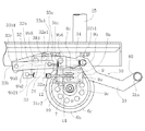
荷台1の後端側に並設した固定キャスタ3の車輪6は、金属製のディスクホイール6aとその周側に配したタイヤゴム6bで構成した既存の車輪体のディスクホイール6aの片面に該ディスクホイール6aに係合するようにして金属製のドーナツ状の係止板6cを重ね合わせて取付けて構成している。係止板6cには、車軸5を中心とする同心円状にして多数の係止孔7(互いに同径)を所定の略等間隔を開けて列設し、規制杆8が任意の係止孔7に係離するようにしてある。
The
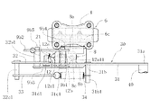
図中、9は係止板6cに対向する側の側部片4a(車輪枠4)に止着したコ字状の装置基枠である。装置基枠9は、基部片9aの上下に上下部片9b,9cを並べて突設したコ字状枠体で成り、基部片9aを側部片4aに重ねて熔接して止着したものである。基部片9aおよび側部片4aには、同じ位置にそれぞれ挿通孔9a1,4a1が形成されている。この装置基枠9の上下部片9b,9c間には、支軸10が止着されており、支軸10に外嵌して組付けたスペーサ筒11を介して作動片12が固着されている。つまり、作動片12は、支軸10に対し回転可能に取り付けられている。
In the figure, 9 is a U-shaped device base frame fixed to the
作動片12は、スペーサ筒11との固着部分を中心にほぼ直交方向に屈曲した前側作動部12aおよび後側作動部12bで成るL形片で成る。前側作動部12aには、トグル機構部30のトグル動作に従って回動する規制片部31c2に内周縁が当り規制杆8のストローク(移動量)を規制するストローク規制長孔12a1が設けられており、このストローク規制長孔12a1には、規制杆先端部8aを係止板6cの係止孔7の方へ押し出すための係合用のコイルバネ(以下、係合用バネという。)21の一端が連結されている。よって、ストローク規制長孔12a1の前後方向の長さによって、係止板6cの係止孔7への規制杆8のストローク(移動量)が決定される。そして、ここでは、規制杆8が係止板6cの係止孔7の方に最大ストローク移動して係止孔7に係合し、車輪6をロック状態にした場合でも、規制杆先端部8aは、ディスクホイール6aに当接しないようにストローク規制長孔12a1の長さを決めている。これにより、車輪6のロック状態でも、規制杆先端部8aはディスクホイール6aに当接しないので、ディスクホイール6aを痛めることを防止できる。また、後側作動部12bでは、規制杆先端部8aを基部片9aおよび側部片4aそれぞれの挿通孔9a1,4a1を介して係止板6cの係止孔7に対し挿抜可能に移動できるように、規制杆8の後端部8bをピン8cにより軸支している。
The actuating
規制杆8は、上述のように基部片9aおよび側部片4aそれぞれの挿通孔9a1,4a1を介して係止板6cの係止孔7に対し挿抜する先端部8aと、作動片12の後側作動部12bにピン8cを介して軸支された後端部8bからなる。
As described above, the
また、装置基枠9の上部片9bには、トグル機構部30のトグル動作に従って回動する規制片部31c2の回動量を規制してトグル動作を規制するトグル動作規制孔9b1が形成されていると共に、その左右両側から上方へトグル機構部30を支持するトグル機構支持板9b2,9b3が立設されている。トグル機構支持板9b2,9b3は、共に、荷台1の下面に沿って前方に延びており、基部片9aおよび側部片4a側のトグル機構支持板9b2のみ、その先端がほぼ直角で下方に折れ曲がり、係合用バネ21の他端部が連結される連結孔9b21が設けられている。そして、トグル機構支持板9b2,9b3は、その長手方向の任意の2箇所で軸部9b4,9b5により連結されており、その軸部9b4,9b5により、トグル機構部30を構成する第1リンク部材31および第2リンク部材32それぞれの中間点に溶着された円筒部31c1,32b1を回動可能に支持している。
The
トグル機構部30は、第1〜第3リンク部材31〜33と、トグル動作用のコイルバネ(以下、トグル動作用バネという。)34をトグル動作可能に連結して、係止孔7に規制杆8を挿入して車輪6を停止させるロック状態と、係止孔7から規制杆8が抜け出し車輪6を回転自在にするフリー状態とを切り替えるよう構成されている。
The
第1リンク部材31は、その後端部31aが荷台1の後端から後方へ突出しており、その後端部31aに踏み付け部40が連結されている。なお、踏み付け部40は、図1に示すように、左右両側の第1リンク部材31間を繋ぐように設けられている。これにより、作業者は、踏み付け部40の場所をあまり意識せず、ロック状態と、フリー状態とを切り替えることが可能となる。また、第1リンク部材31の第1中間点31bには、引張状態のトグル動作用バネ34の一端部を留めるためのバネ留めピン31b1が立設されている。また、第1リンク部材31の第2中間点31cには、円筒部31c1が溶着されており、トグル機構支持板9b2,9b3間を連結する軸部9b4に回動可能に支持されている。円筒部31c1の下端には、装置基枠9の上下部片9bに形成されたトグル動作規制孔9b1を介して、作動片12の前側作動部12aに形成されたストローク規制長孔12a1まで突出して、引張状態の係合用バネ21による規制杆8の係止孔7の方向への挿抜を規制する規制片部31c2が固定されている。また、第1リンク部材31の先端部31dには、第2リンク部材32の後端部32aにトグル動作を第2リンク部材32に伝達するための伝達ピン31d1が設けられている。
As for the
第2リンク部材32の後端部32aには、第1リンク部材31の先端部31dの伝達ピン31d1が嵌まり、第1リンク部材31のトグル動作が伝達される長溝32a1が形成されている。第2リンク部材32の中間点32bには、円筒部32b1が溶着されており、トグル機構支持板9b2,9b3間を連結する軸部9b5に回動可能に支持されている。第2リンク部材32の先端部32cには、第2リンク部材32のトグル動作を第3リンク部材33に伝達するための伝達ピン32c1が設けられている。
The
第3リンク部材33の後端部33aには、引張状態のトグル動作用バネ34の他端部を留めるためのバネ留め孔33a1が形成されている一方、先端部33bには、第2リンク部材32の伝達ピン32c1が嵌まる嵌合孔33b1が形成されている。なお、引張状態のトグル動作用バネ34の一端部は、第1リンク部材31の第1中間点31bのバネ留めピン31b1に留められている。そのため、引張状態のトグル動作用バネ34によりトグル機構部30をトグル動作させ、係止孔7に規制杆8を挿入して車輪6を停止させるロック状態と、係止孔7から規制杆8が抜け出し車輪6を回転自在にするフリー状態とを切り替える。
The
次に、トグル機構部30のトグル動作による車輪6のフリー(解除)状態から車輪6のロック(停止)状態への切り替へについて説明する。
Next, switching from the free (released) state of the
≪車輪6のフリー(解除)状態≫
車輪6がフリー(解除)状態にある場合は、図4および図6に示すように規制杆先端部8aが係止板6cの係止孔7から抜け出た状態にある。この場合、図5に示すように第1リンク部材31の後端部31aに連結された踏み付け部40は、ほぼ荷台1の高さの上死点まで上がった状態にあり、踏み付け部40を下方へ押さない限り車輪6のフリー状態が安定状態にある。つまり、第1リンク部材31の先端部31dおよび第2リンク部材32の後端部32aは、図5に示すようにそれぞれの下死点へ下がった状態にある一方、第2リンク部材32の先端部32cおよび第3リンク部材33の先端部33bは、図5に示すように上死点へ上がった状態にある。
When the
そのため、第1リンク部材31の第2中間点31cに固定された規制片部31c2は、装置基枠9の上部片9bに形成されたトグル動作規制孔9b1の内周縁後側に当接すると共に、作動片12の前側作動部12aに形成されたストローク規制長孔12a1の内周縁後側部12a11に当接し、引張状態の係合用バネ21の引張力に対抗して、上下部片9b,9c間の支軸10に対し回動可能に取り付けられた作動片12の前側作動部12aを後方へ引き寄せる一方、その後側作動部12bを車輪6から離れる方向へ移動させる。これにより、作動片12の後側作動部12bにピン8cにより軸支された規制杆8は、車輪6から離れた方向に位置しており、規制杆先端部8aは、基部片9aおよび側部片4aそれぞれの挿通孔9a1,4a1に挿通しているものの、係止板6cの係止孔7には届かず、係止板6cの係止孔7から抜け出た状態にある。ここで、トグル動作用バネ34は、このフリー状態を安定的に維持するため引張状態にある。なお、係合用バネ21の機能は、後述する規制杆先端部8aが係止孔7の位置と合ったときに、規制杆先端部8aが係止板6cの係止孔7に挿入して係合して、車輪6をロックさせることなので、係合用バネ21の引張力は、トグル動作用バネ34の引張力より数段小さい。これにより、作業者は、この手押し運搬車を走行させる際、ブレーキハンドルを握る必要がなく、主ハンドル25のみ握って走行が可能になる。その結果、例えば、手の小さい女性や、握力の小さい利用者でも使い勝手が向上すると共に、大量の荷物や不安定な荷物を運搬している際でも、主ハンドル25のみ握れば良いので、運搬時の作業負担を軽減できる。なお、この車輪6のフリー(解除)状態は、規制片部31c2がトグル動作規制孔9b1の内周縁後側に当接することにより決まる代わりに、作動片12の前側作動部12aの車輪側端部が装置基枠9の基部片9aに当接して決まるようにしても良いし、その両方が機能するようにしても良い。ここで、車輪6のフリー(解除)状態時に、規制片部31c2がトグル動作規制孔9b1の内周縁後側に当接すると共に、作動片12の前側作動部12aの車輪側端部が装置基枠9の基部片9aに当接するようにすれば、車輪6のフリー(解除)状態時にはトグル動作を2点で支持することが可能になり、より安定したトグル動作が可能になる。
Therefore, the restriction piece 31c2 fixed to the second
≪車輪6のロック(停止)状態≫
<規制杆の先端部が係止孔の位置と合っている場合>
第1リンク部材31の後端部31aの踏み付け部40を踏み付けると、図7に示すように踏み付け部40が下方に下がって、トグル機構部30のトグル動作により踏み付け部40は下死点で安定的に止まる。つまり、トグル機構部30のトグル動作により、車輪6のフリー(解除)状態から車輪6のロック(停止)状態に安定して切り替った状態である。この車輪6のロック(停止)状態の場合で、規制杆先端部8aが係止孔7の位置と合っている場合は、図8および図10に示すように規制杆先端部8aが係止板6cの係止孔7に挿入して係合し、車輪6の回転をロックする。この場合、図9に示すように、第1リンク部材31の後端部31aに連結された踏み付け部40は、荷台1から下死点まで下がった状態にあり、踏み付け部40を上方へ押さない限りそのロック状態が安定状態にある。
<When the tip of the restriction rod matches the position of the locking hole>
When the stepping
つまり、第1リンク部材31の先端部31dおよび第2リンク部材32の後端部32aは、図7および図9に示すようにそれぞれの上死点へ上がった状態にある一方、第2リンク部材32の先端部32bおよび第3リンク部材33の先端部33bは、それぞれの下死点に下がった状態にある。そのため、第1リンク部材31の第2中間点31cに固定された規制片部31c2は、前方に回動して、装置基枠9の上部片9bに形成されたトグル動作規制孔9b1の内周縁先側に当接する。すると、上下部片9b,9c間の支軸10に対し回動可能に取り付けられた作動片12は、引張状態の係合用バネ21の引張力により引っ張られて回動して、作動片12の前側作動部12aは車輪6から離れる方向へ移動する一方、作動片12の後側作動部12bは、車輪6の方向へ移動する。これにより、作動片12の後側作動部12bにピン8cにより軸支された規制杆8は、引張状態の係合用バネ21の引張力により車輪6の方向へ移動して、規制杆先端部8aが係止孔7の位置と合っている場合は、規制杆先端部8aは基部片9aおよび側部片4aそれぞれの挿通孔9a1,4a1を介して、係止板6cの係止孔7に挿入され係合する。そして、トグル動作用バネ34は、このロック(停止)状態を安定的に維持するため、このロック(停止)状態のときも引張状態にある。これにより、作業者は、この手押し運搬車をロック(停止)させる際、踏み付け部40を靴などにより下方へ踏み付けるだけで済むので、簡単にそのロック状態を維持させることができる。
That is, the
<規制杆先端部8aが係止孔7の位置からずれている場合>
ここで、このロック(停止)状態でも、作動片12の前側作動部12aは、引張状態の係合用バネ21の引張力により引っ張られているので、作動片12の前側作動部12aに形成されたストローク規制長孔12a1の内周縁後側部12a11が規制片部31c2に当たるまで、規制杆8の先端を係止板6cの係止孔7の方向へ付勢している。ところで、踏み付け部40が下方に下がって、トグル機構部30のトグル動作により下死点で止まり、車輪6のロック(停止)状態に安定して切り替った状態でも、規制杆先端部8aが係止板6cの係止孔7の位置からずれている場合、規制杆先端部8aが係止孔7と係止孔7との間の係止板6c上面に当接して止まる。この場合、安定状態である車輪6のロック(停止)状態に切り替ったものの、規制杆先端部8aが係止板6cの係止孔7に挿入されてなく、車輪6は回転可能状態にある。この状態では、作動片12の前側作動部12aに形成されたストローク規制長孔12a1の内周縁後側部12a11は、規制片部31c2に当らない。つまり、この場合には、作動片12の前側作動部12aに形成されたストローク規制長孔12a1のほぼ中間点に規制片部31c2が位置することになる。
<When the
Here, even in this locked (stopped) state, the front
しかし、このような場合でも、規制杆先端部8aは、引張状態の係合用バネ21の引張力により係止板6cの係止孔7の方向へ付勢されているので、車輪6がわずか回転し、規制杆先端部8aが係止板6cの係止孔7の位置に合うと、ストローク規制長孔12a1の内周縁後側部12a11が規制片部31c2に当たるまで係止板6cの係止孔7の方向にスライドしてその係止孔7に係合し、車輪6をロック(停止)できるので、トグル動作を利用しても、確実に車輪6をロック(停止)することができる。また、踏み付け部40がトグル機構部30のトグル動作によりその下死点で止まり、車輪6のロック(停止)状態に安定して切り替った際に、規制杆先端部8aが係止板6cの係止孔7の位置からずれていて、係止孔7と係止孔7との間の係止板6c上面に当接した場合でも、規制杆先端部8aは係合用バネ21の引張力により係止板6c上面に押し付けられるものの、それ以上は進まないので、係止板6cや規制杆8、トグル機構部30等に過大な応力がかかることを防止でき、係止板6cを曲げたり、規制杆8が折れ曲がること等を防止できる。その結果、トグル機構を利用して規制杆先端部を係止孔に係合して車輪をロックする手押し運搬車の車輪ロック装置であっても、故障が少なくなり、故障や修理なく末永く使用することが可能となる。
However, even in such a case, the
1 荷台
2 自在キャスタ
3 固定キャスタ
5 車軸
6 車輪
6a ディスクホイール
6c 係止板
7 係止孔
8 規制杆
9 装置基枠
9a 基部片
9b 上部片
9b1 トグル動作規制孔
9c 下部片
12 作動片
12a 前側作動部
12a1 ストローク規制長孔
12b 後側作動部
21 係合用バネ
25 主ハンドル
30 トグル機構部
31 第1リンク部材
31c2 規制片部
32 第2リンク部材
33 第3リンク部材
34 トグル動作用バネ
40 踏み付け部
DESCRIPTION OF
Claims (4)
前記ディスクホイールの片面に間隙を開けて取付けられ、前記車軸を中心とする同心円上に複数の円形の係止孔が所定の間隔で設けられた係止板と、
2以上のリンク部材をトグル動作用バネによりトグル動作可能に連結して、前記係止孔に規制杆を挿入して車輪を停止させるロック状態と、前記係止孔から規制杆が抜け出し車輪を回転自在にするフリー状態とを切り替えるトグル機構部と、
前記トグル機構部における一のリンク部材に設けられ、荷台後端から後方へ突出した状態で上下方向に揺動する踏み付け部と、
前記トグル機構部における一のリンク部材に設けられ、該リンク部材の回動に応じて引張状態の係合用バネによる前記規制杆の係止孔への挿抜を規制する規制片部と、
を有することを特徴とする手押し運搬車の車輪ロック装置。 A wheel lock device for a hand truck that supports a wheel consisting of a disc wheel and a tire rotatably on a pair of side pieces of a wheel frame attached to the lower surface of the loading platform, and a main handle is provided at the rear end of the upper surface of the loading platform. There,
A locking plate attached to one side of the disc wheel with a gap, and a plurality of circular locking holes provided at predetermined intervals on a concentric circle centered on the axle;
Two or more link members are connected so as to be able to perform a toggle operation by a spring for toggle operation, a locked state in which a restriction rod is inserted into the engagement hole to stop the wheel, and the restriction rod comes out of the engagement hole and rotates the wheel. A toggle mechanism that switches between a free state and a free state;
A stepping portion that is provided on one link member in the toggle mechanism portion and swings up and down in a state of protruding backward from the rear end of the loading platform;
A restriction piece provided on one link member in the toggle mechanism, and restricting insertion / extraction of the restriction rod into the locking hole by the engaging spring in a tension state according to rotation of the link member;
A wheel lock device for a handcart transporter characterized by comprising:
係止板側の側部片に止着された装置基枠の上下部片間に、ほぼL型の作動片の中心が回動可能に支持されており、該作動片は、前側作動部および後側作動部からなり、前側作動部には、トグル機構部のトグル動作に従って回動する規制片部に内周縁が当り規制杆のストロークを規制するストローク規制長孔が設けられ、このストローク規制長孔に引張状態の係合用バネの一端が連結される一方、後側作動部には、規制杆先端が係止孔に対し挿抜可能に移動できるよう規制杆後端を軸支しており、トグル機構部が車輪のフリー状態に切り替わった場合は、規制片部が前側作動部のストローク規制長孔の内周縁後側に当接し、後側作動部を車輪から離れる方向へ移動させ、後側作動部に軸支された規制杆先端を係止孔から抜け出た状態におく一方、トグル機構部が車輪のロック状態に切り替わった場合は、規制片部が前方へ回動し、係合用バネの引張力により前側作動部のストローク規制長孔の内周縁後側が規制片部に当って、規制杆先端が係止孔へ挿入し係合するまで、規制杆先端を係止孔の方向へ付勢することを特徴とする手押し運搬車の車輪ロック装置。 In the wheel lock device of the hand cart according to claim 1,
Between the upper and lower pieces of the device base frame fixed to the side piece on the locking plate side, the center of the substantially L-shaped working piece is rotatably supported. It consists of a rear working part, and the front working part is provided with a stroke restricting slot that restricts the stroke of the restricting rod against the inner periphery of the restricting piece that rotates according to the toggle operation of the toggle mechanism. One end of the tension spring is connected to the hole, while the rear actuating portion pivotally supports the rear end of the restriction rod so that the front end of the restriction rod can be inserted into and removed from the locking hole. When the mechanism is switched to the free state of the wheel, the restricting piece comes into contact with the rear side of the inner peripheral edge of the stroke restricting long hole of the front actuating part, and the rear actuating part is moved away from the wheel to act as the rear actuating. While the tip of the regulating rod pivotally supported by the part is left out of the locking hole When the toggle mechanism is switched to the locked state of the wheel, the restricting piece rotates forward, and the inner peripheral rear side of the stroke restricting long hole of the front actuating part hits the restricting piece by the pulling force of the engaging spring. A wheel lock device for a hand cart, wherein the tip of the restriction rod is biased toward the engagement hole until the tip of the restriction rod is inserted and engaged with the engagement hole.
装置基枠の上部片には、トグル機構部のトグル動作に従って回動する規制片部の回動量を規制してトグル動作を規制するトグル動作規制孔が形成されており、
車輪のロック状態時には、規制片部がトグル動作規制孔の内周縁先側に当接して車輪のロック状態時における規制片部の回動が規制される一方、車輪のフリー状態時には、規制片部がトグル動作規制孔の内周縁後側に当接するか、作動片の前側作動部の車輪側端部が装置基枠の基部片に当接するかの少なくとも一方により車輪のフリー状態時における規制片部の回動が規制されることを特徴とする手押し運搬車の車輪ロック装置。 In the wheel lock device of the hand cart according to claim 2,
The upper piece of the device base frame is formed with a toggle operation restriction hole for restricting the toggle operation by restricting the rotation amount of the restriction piece portion that rotates according to the toggle operation of the toggle mechanism portion,
When the wheel is locked, the restricting piece abuts against the inner peripheral edge of the toggle operation restricting hole, and the rotation of the restricting piece when the wheel is locked is restricted. On the other hand, when the wheel is free, the restricting piece Restricting piece portion in the free state of the wheel by at least one of the contact with the rear side of the inner peripheral edge of the toggle operation restricting hole or the wheel side end portion of the front working portion of the actuating piece abutting the base piece of the device base frame The wheel lock device of the handcart is characterized in that the rotation of the wheelbarrow is restricted.
前記係止板とおよびトグル機構部は、荷台後端側の両側の後輪にそれぞれ設けられ、両側の後輪それぞれに設けられた各トグル機構部の対向するリンク部材を連結するように前記踏み付け部が設けられていることを特徴とする手押し運搬車の車輪ロック装置。 In the wheel lock device of the hand cart according to any one of claims 1 to 3,
The locking plate and the toggle mechanism are respectively provided on the rear wheels on both sides of the loading platform rear end side, and the stepping is performed so as to connect the opposing link members of the toggle mechanisms provided on the rear wheels on both sides. A wheel lock device for a hand cart, which is provided with a portion.
Priority Applications (1)
| Application Number | Priority Date | Filing Date | Title |
|---|---|---|---|
| JP2011186073A JP5766552B2 (en) | 2011-08-29 | 2011-08-29 | Wheel locker for wheelbarrow |
Applications Claiming Priority (1)
| Application Number | Priority Date | Filing Date | Title |
|---|---|---|---|
| JP2011186073A JP5766552B2 (en) | 2011-08-29 | 2011-08-29 | Wheel locker for wheelbarrow |
Publications (2)
| Publication Number | Publication Date |
|---|---|
| JP2013047054A JP2013047054A (en) | 2013-03-07 |
| JP5766552B2 true JP5766552B2 (en) | 2015-08-19 |
Family
ID=48010351
Family Applications (1)
| Application Number | Title | Priority Date | Filing Date |
|---|---|---|---|
| JP2011186073A Active JP5766552B2 (en) | 2011-08-29 | 2011-08-29 | Wheel locker for wheelbarrow |
Country Status (1)
| Country | Link |
|---|---|
| JP (1) | JP5766552B2 (en) |
Families Citing this family (2)
| Publication number | Priority date | Publication date | Assignee | Title |
|---|---|---|---|---|
| CN103465948B (en) * | 2013-10-08 | 2016-06-29 | 国网山东省电力公司沂源县供电公司 | A kind of wheel system being realized location hole type locking by angle-shaped piece |
| CN107953919A (en) * | 2017-05-23 | 2018-04-24 | 内蒙古财经大学 | A kind of adjustable steady type circular ring type logistics trolley of handle |
Family Cites Families (2)
| Publication number | Priority date | Publication date | Assignee | Title |
|---|---|---|---|---|
| JP2006240426A (en) * | 2005-03-02 | 2006-09-14 | Ishikawa Seisakusho:Kk | Brake device for handcart |
| JP5002487B2 (en) * | 2008-02-26 | 2012-08-15 | 株式会社石川製作所 | Handcart |
-
2011
- 2011-08-29 JP JP2011186073A patent/JP5766552B2/en active Active
Also Published As
| Publication number | Publication date |
|---|---|
| JP2013047054A (en) | 2013-03-07 |
Similar Documents
| Publication | Publication Date | Title |
|---|---|---|
| JP5506794B2 (en) | Caster with hand brake | |
| JP2010163056A (en) | Carriage braking structure | |
| JP5766552B2 (en) | Wheel locker for wheelbarrow | |
| CN108502008B (en) | Baby carriage | |
| JP5002487B2 (en) | Handcart | |
| JP2025015179A (en) | Hand Cart | |
| WO2014207939A1 (en) | Dolly structure | |
| JP6590427B1 (en) | Battery carrier | |
| JP2009083842A (en) | Crawler type lorry and wheelbarrow for conveyance | |
| GB2428190A (en) | Locking mechanism for castor | |
| JP2013249001A (en) | Double-wheel caster with stopper | |
| JP3535065B2 (en) | Hand truck with brake mechanism | |
| JP6471055B2 (en) | Front motorcycle fixing mechanism for front motorcycle type tricycle | |
| JP5215953B2 (en) | Brake braking structure | |
| JP2019077389A (en) | Component conveyance truck | |
| JP7360994B2 (en) | Spring-type assist device for trolleys and hand trolleys | |
| JP2014051205A (en) | Brake mechanism for handcart | |
| JP2010116045A (en) | Handcart | |
| JP5002469B2 (en) | Handle device for handcart with brake device | |
| JP2001151118A (en) | Handcart | |
| JP2018176827A (en) | Brake unit | |
| JP3230231U (en) | Small electric vehicle | |
| JP2014213720A (en) | Connection mechanism of carriage to driving wheel unit | |
| JP4152428B1 (en) | Wheel drive for wheelchair and wheelchair | |
| JPH011669A (en) | bicycle stand |
Legal Events
| Date | Code | Title | Description |
|---|---|---|---|
| A621 | Written request for application examination |
Free format text: JAPANESE INTERMEDIATE CODE: A621 Effective date: 20140523 |
|
| A977 | Report on retrieval |
Free format text: JAPANESE INTERMEDIATE CODE: A971007 Effective date: 20150407 |
|
| TRDD | Decision of grant or rejection written | ||
| A01 | Written decision to grant a patent or to grant a registration (utility model) |
Free format text: JAPANESE INTERMEDIATE CODE: A01 Effective date: 20150526 |
|
| A61 | First payment of annual fees (during grant procedure) |
Free format text: JAPANESE INTERMEDIATE CODE: A61 Effective date: 20150617 |
|
| R150 | Certificate of patent or registration of utility model |
Ref document number: 5766552 Country of ref document: JP Free format text: JAPANESE INTERMEDIATE CODE: R150 |
|
| R250 | Receipt of annual fees |
Free format text: JAPANESE INTERMEDIATE CODE: R250 |
|
| R250 | Receipt of annual fees |
Free format text: JAPANESE INTERMEDIATE CODE: R250 |
|
| R250 | Receipt of annual fees |
Free format text: JAPANESE INTERMEDIATE CODE: R250 |
|
| R250 | Receipt of annual fees |
Free format text: JAPANESE INTERMEDIATE CODE: R250 |
|
| R250 | Receipt of annual fees |
Free format text: JAPANESE INTERMEDIATE CODE: R250 |
|
| R250 | Receipt of annual fees |
Free format text: JAPANESE INTERMEDIATE CODE: R250 |
|
| R250 | Receipt of annual fees |
Free format text: JAPANESE INTERMEDIATE CODE: R250 |
|
| R250 | Receipt of annual fees |
Free format text: JAPANESE INTERMEDIATE CODE: R250 |
|
| R250 | Receipt of annual fees |
Free format text: JAPANESE INTERMEDIATE CODE: R250 |