JP5750737B2 - Main roller for wire saw, roller body and manufacturing method thereof - Google Patents
Main roller for wire saw, roller body and manufacturing method thereof Download PDFInfo
- Publication number
- JP5750737B2 JP5750737B2 JP2009144468A JP2009144468A JP5750737B2 JP 5750737 B2 JP5750737 B2 JP 5750737B2 JP 2009144468 A JP2009144468 A JP 2009144468A JP 2009144468 A JP2009144468 A JP 2009144468A JP 5750737 B2 JP5750737 B2 JP 5750737B2
- Authority
- JP
- Japan
- Prior art keywords
- roller
- carbon fiber
- wire saw
- main roller
- main
- Prior art date
- Legal status (The legal status is an assumption and is not a legal conclusion. Google has not performed a legal analysis and makes no representation as to the accuracy of the status listed.)
- Active
Links
Images

Landscapes
- Processing Of Stones Or Stones Resemblance Materials (AREA)
- Finish Polishing, Edge Sharpening, And Grinding By Specific Grinding Devices (AREA)
- Mechanical Treatment Of Semiconductor (AREA)
Description
本発明は、ワイヤソーに用いられるメインローラーと、このメインローラーを構成するローラー本体と、メインローラーの製造方法に関するものである。 The present invention relates to a main roller used for a wire saw, a roller body constituting the main roller, and a method for manufacturing the main roller.
単結晶・多結晶などシリコンインゴット等の半導体の切断には、従来、内周刃切断機やバンドソーが使われていたが、切断ロスを少なくし、単位時間あたりの生産性を向上させるため、ワイヤソーが一般的に用いられるようになってきた。ワイヤソーの概略構成を第3図に示す。ワイヤソー1は、インゴット等の被削物2との管でワイヤ3を往復させながら、徐々に新しいワイヤを供給するよう構成されているおり、ワイヤ3は予めリール4に数キロメートル巻かれている。メインローラー5同士は、所定の間隔で配置されており、メインローラー5近傍には、切削液ノズル6が設けられている。メインローラー5の外周面には、被削物2の所望する厚みに応じて、溝が設けられている。2つのリール4の間で両端が巻き付けられたワイヤ3は、この溝にガイドされながら、メインローラー5の間を往復するよう張架されている。
For cutting semiconductors such as silicon ingots such as single crystals and polycrystals, an inner peripheral cutting machine and a band saw have been used in the past, but in order to reduce cutting loss and improve productivity per unit time, a wire saw Has become commonly used. FIG. 3 shows a schematic configuration of the wire saw. The
ワイヤソー1を用いて被削物2を切断する場合、メインローラー5及びリール4をモータで回転させ、ワイヤ3を2つのリール4の間で往復運動させる。このワイヤ3に被削物2を押圧することにより、被削物2は多数枚の基板に加工される。この際、メインローラー5の外周面に形成された溝と被削物2の間には、ワイヤ3の走行方向に切削液ノズル6から、砥粒が液体に分散された、いわゆるスラリが供給され、ワイヤ3の走行方向に同伴され切削部へ到達する。
When the workpiece 2 is cut using the wire saw 1, the
特開2001−138204号公報に記載されているように、S45C等の機械構造用炭素鋼と機械構造用軸受部を溶接施工によって接合し、メインローラーを構成する。その外周面に樹脂を巻きつけ、ワイヤガイド溝を作成するのが一般的である。 As described in Japanese Patent Application Laid-Open No. 2001-138204, a mechanical structure carbon steel such as S45C and a mechanical structure bearing are joined by welding to constitute a main roller. Generally, a resin is wound around the outer peripheral surface to form a wire guide groove.
ワイヤソーは、生産性を向上させること、一度に多量の基板を切断加工することが求められている。そこで、切削面積を増加させるために、メインローラーは大型化される傾向にあり、これに伴いメインローラーの重量が大きなものとなっている。メインローラーを軸心と平行方向に長軸化すると、張架されるワイヤ数に比例して、ワイヤ張力が増加し、結果として大きな曲げ応力が発生する。このため、長軸化するだけでなく、メインローラーの大径化も合わせて行う必要があり、さらに重量は増加する。 Wire saws are required to improve productivity and to cut a large number of substrates at once. Therefore, in order to increase the cutting area, the main roller tends to be enlarged, and the weight of the main roller is increased accordingly. When the main roller is elongated in the direction parallel to the axis, the wire tension increases in proportion to the number of wires stretched, resulting in a large bending stress. For this reason, it is necessary not only to make the shaft longer, but also to increase the diameter of the main roller, which further increases the weight.
メインローラー表面のワイヤガイド溝は、消耗すると形状の崩れた溝を旋盤などで切削し新しい溝を作成するため、メインローラーを取り外す。そのため、メインローラーの重量増加は作業性を悪化させ、好ましくない。さらに、機械構造用炭素鋼をメインローラーの材質として用いると、加工時に発生する熱によってメインローラーが熱膨張し、基板の面精度に悪影響を及ぼす。メインローラーに伝達される熱は、大きく分けて2つあると考えられる。1つ目は、ワイヤソー本体のスピンドルを円滑に回転させるための、ベアリングの摺動発熱である。この対策として、ワイヤソーのベアリング部とスピンドル内部を水などの液体によって、冷却する機構を備えた装置があるが、メインローラー内部構造やワイヤソー本体の機構が複雑となるため、好ましくない。2つ目は、ワイヤとワイヤをガイドしている溝との接触により発生する摩擦熱である。 When the wire guide groove on the surface of the main roller is consumed, the main roller is removed in order to create a new groove by cutting the broken groove with a lathe. Therefore, an increase in the weight of the main roller deteriorates workability and is not preferable. Furthermore, when carbon steel for machine structure is used as the material of the main roller, the main roller is thermally expanded by heat generated during processing, which adversely affects the surface accuracy of the substrate. The heat transferred to the main roller is considered to be roughly divided into two. The first is the sliding heat generation of the bearing for smoothly rotating the spindle of the wire saw body. As a countermeasure, there is a device having a mechanism for cooling the inside of the wire saw bearing and the spindle with a liquid such as water, but this is not preferable because the internal structure of the main roller and the mechanism of the wire saw body are complicated. The second is frictional heat generated by contact between the wire and the groove guiding the wire.
特開2001−138204号公報には、このメインローラーを、金属・セラミックス複合材料製支持部と、それに接着されたアルミナ製ローラーとで構成し、メインローラーの重量を軽減すると共に、摩擦熱を抑制し、被削物の加工精度を向上させることが記載されている。同公報の[0009]段落には、ワイヤソーメインローラー支持部を金属−セラミックス複合体で製作することが記載されている。同公報の表1には、種々の金属−セラミックス複合材料の比重が記載されている。 Japanese Patent Laid-Open No. 2001-138204 discloses that this main roller is composed of a metal / ceramic composite material support and an alumina roller bonded to the main roller to reduce the weight of the main roller and suppress frictional heat. In addition, it is described that the processing accuracy of the work is improved. The paragraph [0009] of the publication describes that the wire saw main roller support is made of a metal-ceramic composite. Table 1 of the publication describes the specific gravity of various metal-ceramic composite materials.
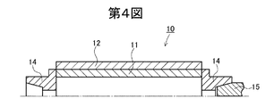
特開平11−245156号公報には、第4図のように、メインローラー10を、スーパーインバーなどの低熱膨張性金属材よりなるメインローラー支持シャフト11と、このシャフトの両端にそれぞれ摩擦圧接により取り付けられたS45Cなどの機械構造用炭素鋼製軸受部14と、シャフト外周に設けられた溝付きスリーブ12とで構成することにより、切断面の精度を高めることが記載されている。符号15はメインローラー10を支持して回転駆動させるためのスピンドルを示す。同公報の[0007]段落には、メインローラーの熱膨張係数を1×10⁻⁶/℃以下とすることが記載されている。
In Japanese Patent Laid-Open No. 11-245156, as shown in FIG. 4, the
特許文献1(特開2001−138204)のように、メインローラーの構成材をセラミックス又は金属・セラミックス複合体とすることで、鋼製メインローラーと比較して熱膨張係数および比重が小さくなるものの、比重はさらに十分小さいことが望まれる。特許文献2(特開平11−245156)のスーパーインバーは、熱膨張係数は十分小さいが、比重は機械構造用炭素鋼よりも大きく、定期的に交換が必要なメインローラーの材質として使用するには不向きである。さらに重量の増加は、単位時間あたりの平均線速を向上させる、即ち高速回転による加工効率の向上のためには好ましくない。 Like patent document 1 (Unexamined-Japanese-Patent No. 2001-138204), although the component material of a main roller is made into ceramics or a metal ceramic composite, although a thermal expansion coefficient and specific gravity become small compared with a steel main roller, It is desired that the specific gravity is sufficiently small. The Super Invar of Patent Document 2 (Japanese Patent Laid-Open No. 11-245156) has a sufficiently small coefficient of thermal expansion, but has a specific gravity greater than that of carbon steel for mechanical structures, and is used as a material for a main roller that needs to be replaced periodically. It is unsuitable. Furthermore, an increase in weight is not preferable for improving the average linear velocity per unit time, that is, for improving the processing efficiency by high-speed rotation.
本発明は、上記従来の問題点を解決し、低熱膨張であると共に、軽量かつ高強度であり、高速回転させてインゴット等を精度よく、かつ効率よく切断することができるワイヤソー用メインローラーと、そのローラー本体及び製造方法を提供することを目的とする。 The present invention solves the above-mentioned conventional problems, has a low thermal expansion, is lightweight and high in strength, and can be rotated at high speed to accurately and efficiently cut an ingot and the like, and a wire saw main roller, It aims at providing the roller main body and a manufacturing method.
本発明者らは、上記問題を解決すべく鋭意研究した結果、炭素繊維強化プラスチックス(以下、「CFRP」と略記する場合がある。)が、低熱膨張率であるとともに軽量で、しかも必要な強度及び剛性を満たすことから、ワイヤソーのメインローラー材料として、好適であることを見出した。本発明は、かかる知見に基づくものである。 As a result of diligent research to solve the above problems, the present inventors have found that carbon fiber reinforced plastics (hereinafter sometimes abbreviated as “CFRP”) has a low thermal expansion coefficient, is lightweight, and is necessary. Since the strength and rigidity are satisfied, it has been found to be suitable as a main roller material for a wire saw. The present invention is based on such knowledge.
請求項1のワイヤソー用メインローラーは、筒状のローラー本体と、該ローラー本体の外周を取り巻く筒状の外装体とを有し、該外装体の外周面にワイヤ溝が設けられたワイヤソー用メインローラーにおいて、該ローラー本体が炭素繊維強化プラスチックス製であって、該炭素繊維強化プラスチックスの炭素繊維が、前記ローラー本体の軸方向に対し0〜±20°方向に延在する第1の炭素繊維と、該軸方向に対して±30〜±60°の方向に延在する第2の炭素繊維と、該軸方向に対して±80〜±90°の方向に延在する第3の炭素繊維とを含み、全炭素繊維に対する第1の炭素繊維の割合が20%以上であり、第2の炭素繊維の割合が20%以上であり、第3の炭素繊維の割合が6.7%以上であることを特徴とするものである。
The main roller for a wire saw according to
請求項2のワイヤソー用メインローラーは、請求項1において、前記外装体が合成樹脂又はセラミックス製であることを特徴とするものである。
The main roller for a wire saw according to claim 2 is characterized in that, in
請求項3のワイヤソー用メインローラーは、請求項1又は2において、前記外装体とローラー本体との間に金属製スリーブが介在していることを特徴とするものである。 The main roller for a wire saw according to a third aspect is characterized in that, in the first or second aspect, a metal sleeve is interposed between the exterior body and the roller body.
請求項4のワイヤソー用メインローラーは、請求項1ないし3のいずれか1項において、金属製のボス部が前記ローラー本体の両端部または一端部に固着されていることを特徴とするものである。 The main roller for a wire saw according to a fourth aspect is characterized in that, in any one of the first to third aspects, a metal boss is fixed to both ends or one end of the roller body. .
請求項5のワイヤソー用メインローラーは、請求項4において、前記ローラー本体の両端部の全面または、一端部の全面に前記金属製のボス部が固着されていることを特徴とするものである。 According to a fifth aspect of the present invention, the wire saw main roller according to the fourth aspect is characterized in that the metal boss is fixed to the entire surface of both end portions or one end portion of the roller body.
請求項6のワイヤソー用メインローラーは、請求項1ないし5のいずれか1項において、前記ローラー本体の軸方向の熱膨張係数が−1.5×10⁻⁶〜+1.5×10⁻⁶/℃であることを特徴とするものである。
The main roller for wire saw according to
請求項7のワイヤソー用メインローラーのローラー本体は、ワイヤソー用メインローラーのローラー本体において、炭素繊維強化プラスチックス製であって、該炭素繊維強化プラスチックスの炭素繊維が、前記ローラー本体の軸方向に対し0〜±20°方向に延在する第1の炭素繊維と、該軸方向に対して±30〜±60°の方向に延在する第2の炭素繊維と、該軸方向に対して±80〜±90°の方向に延在する第3の炭素繊維とを含み、全炭素繊維に対する第1の炭素繊維の割合が20%以上であり、第2の炭素繊維の割合が20%以上であり、第3の炭素繊維の割合が6.7%以上であることを特徴とするものである。 The roller body of the main roller for wire saw according to claim 7 is made of carbon fiber reinforced plastics in the roller body of the main roller for wire saws, and the carbon fibers of the carbon fiber reinforced plastics are arranged in the axial direction of the roller body. First carbon fiber extending in the direction of 0 to ± 20 °, second carbon fiber extending in the direction of ± 30 to ± 60 ° with respect to the axial direction, and ± with respect to the axial direction A third carbon fiber extending in the direction of 80 to ± 90 °, the ratio of the first carbon fiber to the total carbon fiber is 20% or more, and the ratio of the second carbon fiber is 20% or more. And the ratio of the third carbon fiber is 6.7% or more .
請求項8のワイヤソー用メインローラーの製造方法は、請求項1ないし7のいずれか1項に記載のワイヤソー用メインローラーを製造する方法であって、前記炭素繊維強化プラスチックス製のローラー本体に対し筒状の外装体を嵌着した後、外装体の外周面にワイヤ溝を形成することを特徴とするものである。
The manufacturing method of the main roller for wire saws of Claim 8 is a method of manufacturing the main roller for wire saws of any one of
請求項9のワイヤソー用メインローラーの製造方法は、請求項1ないし7のいずれか1項に記載のワイヤソー用メインローラーを製造する方法であって、前記炭素繊維強化プラスチックス製のローラー本体に対し筒状の金属製スリーブを嵌着し、該スリーブの外周側に筒状の外装体を嵌着後、外装体の外周面にワイヤ溝を形成することを特徴とするものである。
The manufacturing method of the main roller for wire saws of Claim 9 is a method of manufacturing the main roller for wire saws of any one of
請求項10のワイヤソー用メインローラーの製造方法は、請求項1ないし7のいずれか1項に記載のワイヤソー用メインローラーを製造する方法であって、前記炭素繊維強化プラスチックス製のローラー本体を金型内に配置し、ローラー本体の外周と金型内周面との間に樹脂材料を供給して硬化させて外装体を形成し、脱型後、外装体にワイヤ溝を形成することを特徴とするものである。
The method for manufacturing a main roller for a wire saw according to
本発明では、ワイヤソー用メインローラーのローラー本体をCFRPにて構成している。このCFRPは、低比重かつ高強度であると共に、熱膨張係数が低い。そのため、ワイヤソー用メインローラーを高速回転させてインゴット等を効率よく切断することができると共に、ローラー本体の軸方向の熱膨張係数を−1.5×10⁻⁶〜+1.5×10⁻⁶/℃程度の低熱膨張率とすることが可能であることから切断精度を向上させることができる。 In this invention, the roller main body of the main roller for wire saws is comprised by CFRP. This CFRP has a low specific gravity and high strength, and a low coefficient of thermal expansion. Therefore, the wire saw main roller can be rotated at a high speed to efficiently cut the ingot and the like, and the axial thermal expansion coefficient of the roller body is −1.5 × 10 −6 to + 1.5 × 10 −6 / Since it is possible to make the coefficient of thermal expansion as low as about ° C., the cutting accuracy can be improved.
本発明では、ローラー本体と外装体との間に金属製スリーブを介在させてもよい。このようにすれば、切削液の種類を選ぶことなく、CFRP製ローラー本体の使用が可能となる。また、切断中にワイヤが断線した場合でも、CFRP製ローラー本体部が直接傷つくことを防止できる。 In the present invention, a metal sleeve may be interposed between the roller body and the exterior body. In this way, the CFRP roller body can be used without selecting the type of cutting fluid. Further, even when the wire is disconnected during cutting, the CFRP roller body can be prevented from being directly damaged.
本発明では、金属製のボス部をローラー本体の両端部または一端部に設けることにより、ワイヤソー用メインローラーをワイヤソー装置のメインローラー駆動部に強固に取り付けることが可能となる。 In this invention, it becomes possible to attach the main roller for wire saws to the main roller drive part of a wire saw apparatus firmly by providing a metal boss | hub part in the both ends or one end part of a roller main body.
また、ローラー本体を構成するCFRPの炭素繊維を、軸方向(ローラー本体の軸心と平行方向。以下、同様)と、この軸方向に対して交差方向とに延在させることにより、ワイヤソー用メインローラーの必要とする強度・剛性を維持しながら低熱膨張率とすることが可能である。 Also, the CFRP carbon fiber constituting the roller body is extended in the axial direction (a direction parallel to the axis of the roller body; hereinafter the same) and in a direction intersecting with the axial direction. It is possible to achieve a low coefficient of thermal expansion while maintaining the strength and rigidity required by the roller.
本発明のワイヤソー用メインローラーを製造する場合、CFRP製ローラー本体に対し、必要に応じ金属製スリーブを嵌着した後、筒状外装体を嵌着し、次いで外装体にワイヤ溝を形成する。即ち、例えば予めCFRP製ローラー本体の外径に適合するように樹脂を硬化させて円筒状の外装体を形成し、この外装体の中空部にローラー本体を圧入した後、ワイヤ溝を形成する。もしくは、CFRP製ローラー本体を金型内に配置し、ローラー本体と金型内周面との間に樹脂材料を注入して外装体を形成し、脱型後、ワイヤ溝を形成する。このようにワイヤ溝を後から形成することにより、ワイヤ溝を高精度にて設けることができる。 When manufacturing the main roller for wire saws of the present invention, a metal sleeve is fitted to the CFRP roller body as necessary, and then a cylindrical outer package is fitted, and then a wire groove is formed in the outer package. That is, for example, a resin is cured in advance so as to match the outer diameter of the CFRP roller body to form a cylindrical exterior body, and after the roller body is press-fitted into the hollow portion of the exterior body, a wire groove is formed. Alternatively, a CFRP roller body is placed in a mold, a resin material is injected between the roller body and the inner peripheral surface of the mold to form an exterior body, and after demolding, a wire groove is formed. Thus, the wire groove can be provided with high accuracy by forming the wire groove later.
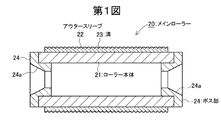
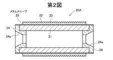
以下、図面を参照して実施の形態について説明する。第1図は実施の形態に係るワイヤソー用メインローラーのメインローラー軸心線方向の断面図、第2図は別の実施の形態に係るワイヤソー用メインローラーのメインローラー軸心線方向の断面図である。 Hereinafter, embodiments will be described with reference to the drawings. FIG. 1 is a cross-sectional view in the direction of the main roller axis of the wire saw main roller according to the embodiment, and FIG. 2 is a cross-sectional view in the direction of the main roller axis of the wire saw main roller according to another embodiment. is there.
第1図の実施の形態に係るワイヤソー用メインローラー20は、円筒状のCFRP製のローラー本体21と、該ローラー本体21の外周に装着された外装体としての円筒状のアウタースリーブ22と、ローラー本体21の両端に装着されたボス部24とを備えている。なお、ボス部24は、ローラー本体21の一端側にのみ装着されてもよい。
A wire saw main roller 20 according to the embodiment of FIG. 1 includes a cylindrical
CFRP製ローラー本体21は、通常は外径(直径)Dが100〜500mm、特に150〜400mm程度であり、内径が20〜500mm、特に30〜300mm程度である。肉厚(外周半径と内周半径との差)はローラー本体21の直径の2〜49%、特に5〜40%程度であることが好ましい。ローラー本体21の軸心線方向長さLは、通常50〜2000mm、特に300〜1200mm程度である。
The
CFRPの炭素繊維としては、平均繊維径が5〜20μm、好ましくは7〜12μmであり、引張弾性率が100〜1000GPa、特に200〜800GPa程度のものが好適である。CFRPのマトリックスとしては、エポキシ、フェノール、ビスマレイミド等の熱硬化性樹脂、PEEK(ポリエーテルエーテルケトン)、ポリアミド、ポリカーボネート等の熱可塑性樹脂などが好適である。CFRP中に占める炭素繊維の体積%は40〜80%、特に50〜70%が好適である。 CFRP carbon fibers having an average fiber diameter of 5 to 20 μm, preferably 7 to 12 μm, and a tensile modulus of 100 to 1000 GPa, particularly about 200 to 800 GPa are suitable. As the CFRP matrix, a thermosetting resin such as epoxy, phenol, bismaleimide, or a thermoplastic resin such as PEEK (polyether ether ketone), polyamide, or polycarbonate is preferable. The volume percentage of carbon fiber in CFRP is preferably 40 to 80%, particularly 50 to 70%.
ただし、これらの寸法、材料等は好適な一例を示すものであって、本発明はこれらに限定されるものではない。 However, these dimensions, materials, etc. show a suitable example, and the present invention is not limited to these.
CFRP中の炭素繊維としては、ローラー本体21の軸方向に配向したものと、軸方向に対し角度θにて交差方向に配向したものとを含むことが好ましい。また、角度θが異なる2以上の交差方向炭素繊維を含んでもよい。
The carbon fibers in the CFRP preferably include those oriented in the axial direction of the
好適な炭素繊維の配向例の一例を示すと次の通りである。
軸方向に対し0〜±20°方向の炭素繊維:20〜80%(全炭素繊維に対する割合
。以下、同様。)
軸方向に対し±30〜±60°方向の炭素繊維:20〜80%
軸方向に対し±80〜±90°方向の炭素繊維: 0〜20%
An example of a preferred carbon fiber orientation example is as follows.
Carbon fiber in the direction of 0 to ± 20 ° relative to the axial direction: 20 to 80% (ratio to the total carbon fiber
. The same applies hereinafter. )
Carbon fiber in the direction of ± 30 to ± 60 ° with respect to the axial direction: 20 to 80%
Carbon fiber in the direction of ± 80 to ± 90 ° with respect to the axial direction: 0 to 20%
好適な一例にあっては、ローラー本体21の最内層に軸方向に対し90°方向の炭素繊維配向層を設け、その上に中間層として、0〜±20°の配向層を設け、最外層に±30〜±60°の配向層を設ける。ただし、最内層、中間層、最外層の配置をこれとは逆としても良く、また当該積層を繰り返す等、他の構成としてもよい。
In a preferred example, a carbon fiber alignment layer having a direction of 90 ° with respect to the axial direction is provided on the innermost layer of the
このCFRP製ローラー本体の軸方向の熱膨張係数は−1.5×10⁻⁶〜+1.5×10⁻⁶/℃であることが好ましい。 The thermal expansion coefficient in the axial direction of the CFRP roller body is preferably −1.5 × 10 −6 to + 1.5 × 10 −6 / ° C.
ローラー本体21を製造するには、フィラメントワインディング法によるのが好適である。即ち、マンドレルの周囲に未硬化合成樹脂を付着させた炭素繊維を例えば、上記の配向例のように巻き付けた後、合成樹脂を硬化させ、次いでマンドレルを脱芯する。
In order to manufacture the
ボス部24は、S45C等の機械構造用炭素鋼、アルミ合金、低熱膨張率金属材料などによって構成するのが好ましい。このボス部24には、ワイヤソー装置のスピンドルと係合させるためのテーパ部24aが設けられている。ローラー本体21とボス部24とは、接着剤を用いて固着させる。
The
アウタースリーブ22は、好ましくは合成樹脂又はセラミックスよりなる。アウタースリーブの合成樹脂としては、ポリウレタン、ポリエチレンなどが好適である。合成樹脂製アウタースリーブの場合、厚さは1〜30mm、特に3〜20mm程度が好適である。
The
セラミックスとしては、アルミナ(Al2O3)、炭化珪素(SiC)、窒化ケイ素(Si3N4)、窒化アルミニウム(AlN)、ステアタイト(MgO・SiO2)、ジルコニア(ZrO2)等が好適である。セラミックス製アウタースリーブの場合、厚さは0.2〜30mm、特に0.5〜10mm程度が好適である。 As the ceramic, alumina (Al 2 O 3 ), silicon carbide (SiC), silicon nitride (Si 3 N 4 ), aluminum nitride (AlN), steatite (MgO · SiO 2 ), zirconia (ZrO 2 ) and the like are suitable. It is. In the case of a ceramic outer sleeve, the thickness is preferably 0.2 to 30 mm, particularly about 0.5 to 10 mm.
アウタースリーブ22が熱硬化性合成樹脂よりなる場合は、ローラー本体21を円筒形金型の軸心位置に配置した後、ローラー本体21の外周面と金型の内周面との間に未硬化合成樹脂を流し込み、その後、加熱して合成樹脂を硬化させ、アウタースリーブ22とローラー本体21とを一体化させることができる。また、セラミックス製アウタースリーブなどは、予め成形された後、ローラー本体21に外嵌めして、一体化することができる。さらに、セラミックス製アウタースリーブは、ローラー本体21の最表面に溶射により直接形成させてもよい。
When the
また、同様にアウタースリーブ22は、予め成形された後、ローラー本体21に外嵌めし、接着剤によって接着されても良い。接着剤としては、エポキシ系接着剤、アクリル系接着剤などを用いることができるが、これに限定されない。
Similarly, the
アウタースリーブ22とローラー本体21とを一体化させた後、又はローラー本体21に装着される前のアウタースリーブ22に対し、溝23を形成する。
A
溝23のピッチは、スライスされたウェハ等の厚みに対応したものとなる。溝23の断面形状は、V形が好適である。溝23は、切削加工によってアウタースリーブ22の外周面に設けるのが、簡便で好適であるが、アウタースリーブの成形用金型に凸部を設けておくことによって形成されてもよい。
The pitch of the
第2図の実施の形態に係るワイヤソー用メインローラー20Aは、ローラー本体21の外周面とアウタースリーブ22の内周面との間に金属製スリーブ(以下、メタルスリーブという。)25を設けたものである。この実施の形態では、メタルスリーブ25はローラー本体21とボス部24の外周面の全体を覆っている。
The wire saw
このメタルスリーブ25の材質としては、耐食性の良好なステンレス、アルミニウム、アルミニウム合金、銅、銅合金、低熱膨張率金属材料などが好適である。メタルスリーブ25の厚みは0.1〜5mm、特に0.2〜2mm程度が好適である。このメタルスリーブ25は予め円筒形に成形された後、ローラー本体21に外嵌めされ、必要に応じ接着剤で接着されたものである。
As the material of the
このメタルスリーブ25の外周面にメッキ層を設けてもよい。メッキ金属としては、耐食性の良好なニッケル、クロムなどが好適である。また、ローラー本体21に、直接ダイヤモンドライクカーボン膜(以下、DLC膜)などを成長させることも好適である。
A plating layer may be provided on the outer peripheral surface of the
このようなメタルスリーブ25やメッキ層または、DLC膜を設けることにより、切削液などによるCFRP製ローラー本体21の劣化が防止される。
By providing such a
第2図のその他の構成は第1図と同様であり、同一符号は同一部分を示している。 The other structure of FIG. 2 is the same as that of FIG. 1, and the same code has shown the same part.
このように構成されたメインローラー20,20Aは、前記第3図のようにワイヤソー装置に組み込まれ、単結晶・多結晶シリコンインゴット、GaAs、GaN,GaP,サファイア、SiC、III族窒化物半導体等の切断に用いられる。
The
このメインローラー20,20Aは、ローラー本体21がCFRP製であり、低比重であり、鋼製ローラー本体に比べて軽量である。そのため、メインローラー20,20Aを高速回転させてインゴット等を効率よく切断することができる。また、CFRPは低熱膨張であるので、インゴット等を高精度にて切断することができる。
In the
なお、この実施の形態では、金属製ボス部24をローラー本体21に固着しているので、メインローラー20,20Aをワイヤソーに確実に装着することができる。
In this embodiment, since the
第1図のメインローラー20は、メタルスリーブを有しておらず、その分だけさらに軽量である。 The main roller 20 in FIG. 1 does not have a metal sleeve and is lighter by that amount.
第2図のメインローラー20Aでは、メタルスリーブ25を設けたことにより、前述の通り、CFRPに影響を与える切削液を使用した場合であっても、CFRP製ローラー本体21の劣化が防止されるので、メインローラー20Aの耐久性が向上する。
In the
なお、メインローラー20,20Aを使用していると、アウタースリーブ22が次第に磨耗してくるので、適宜アウタースリーブを交換する。第2図のようにメタルスリーブ25を装着してあると、ローラー本体21を傷つけることなくアウタースリーブ22を容易に交換することができる。また、メタルスリーブを装着しない場合、ローラー本体21の外装部に、0.1〜5mm、特に好ましくは、0.5〜1.5mm程度の厚さのCFRP製保護層を設けてもよい。
When the
ワイヤソーの運転条件の好適な一例を次に示す。
ワイヤ径:40〜250μm
ワイヤ線速:300〜1500m/min
ワイヤ張力:ワイヤ線径に応じ、5〜50N
ワイヤ往復サイクル:加減速0.2〜10s、一定速度10〜60s
(サイクル不問、一方向送りでも可)
切断速度:5mm/h〜100mm/h
新線供給量:1〜20m/min
砥粒:GC#400〜#3000
A preferred example of the operating conditions of the wire saw is shown below.
Wire diameter: 40-250 μm
Wire drawing speed: 300-1500 m / min
Wire tension: 5-50N depending on the wire diameter
Wire reciprocation cycle: acceleration / deceleration 0.2-10s, constant speed 10-60s
(No cycle, one-way feed is acceptable)
Cutting speed: 5 mm / h to 100 mm / h
New wire supply: 1 to 20 m / min
Abrasive grains: GC # 400- # 3000
なお、ワイヤソーは、ワイヤ自体にダイヤを固着しているいわゆる、固定砥粒ワイヤで被削物を加工するよう構成したものであってもよい。 Note that the wire saw may be configured to process a workpiece with a so-called fixed abrasive wire in which a diamond is fixed to the wire itself.
以下に、本発明の具体的な実施態様について説明するが、本発明はこれらに限定されるものではない。 Hereinafter, specific embodiments of the present invention will be described, but the present invention is not limited thereto.
[実施態様1]
直径130mmのマンドレルを用いて、フィラメントワインディング法により、外径250mm、内径165mmのCFRP製ローラー本体を作製する。即ち、このマンドレルの外周に、未硬化エポキシ樹脂を付着させた、平均繊維径10μm、引張弾性率640GPaの炭素繊維(三菱樹脂(株)製「K63712」)を巻きつける。積層構成および比率を表1に示す。炭素繊維角度は、軸方向を0°としている。
[Embodiment 1]
A CFRP roller body having an outer diameter of 250 mm and an inner diameter of 165 mm is produced by a filament winding method using a mandrel having a diameter of 130 mm. That is, a carbon fiber having an average fiber diameter of 10 μm and a tensile elastic modulus of 640 GPa (“K63312” manufactured by Mitsubishi Plastics, Inc.), to which an uncured epoxy resin is attached, is wound around the outer periphery of the mandrel. The laminated structure and ratio are shown in Table 1. The carbon fiber angle is 0 ° in the axial direction.

次いで、硬化炉でエポキシ樹脂を150℃にて硬化させた後に、マンドレルを脱芯して、CFRP製ローラー本体を製作する。このCFRPの炭素繊維含有割合は55体積%である。また、このCFRP製ローラー本体の重量は、27kgであり、軸方向の熱膨張係数は、−0.9×10⁻⁶/℃である。 Next, after the epoxy resin is cured at 150 ° C. in a curing furnace, the mandrel is decentered to produce a CFRP roller body. The carbon fiber content of CFRP is 55% by volume. The weight of the CFRP roller body is 27 kg, and the thermal expansion coefficient in the axial direction is −0.9 × 10 −6 / ° C.
このCFRP製ローラー本体の長さを550mmで切断し、S45C製のボス部をエポキシ系接着剤にて固着する。 The length of the CFRP roller body is cut at 550 mm, and the S45C boss is fixed with an epoxy adhesive.
これとは別に、内径250mm、外径280mm、長さ530mmのポリウレタン製のアウタースリーブを金型によって成形する。上記のCFRP製ローラー本体の外周面にエポキシ系接着剤を付着させておき、このアウタースリーブを外嵌めし、アウタースリーブとローラー本体とを一体化させる。 Separately, an outer sleeve made of polyurethane having an inner diameter of 250 mm, an outer diameter of 280 mm, and a length of 530 mm is molded by a mold. An epoxy-based adhesive is attached to the outer peripheral surface of the CFRP roller main body, and the outer sleeve is externally fitted to integrate the outer sleeve and the roller main body.
その後、アウタースリーブの外周面に、V字形のワイヤ溝を372μm間隔で、1350本切削加工し、メインローラーを形成する。 Thereafter, 1350 V-shaped wire grooves are cut on the outer peripheral surface of the outer sleeve at intervals of 372 μm to form a main roller.
[実施態様2]
軸方向に対して、±45°の方向に炭素繊維として三菱樹脂(株)製「K63A12」(平均繊維径10μm、引張弾性率790GPa)を配向させ、±15°及び90°方向にそれぞれ東レ社製「T700」(平均繊維径7μm、引張弾性率230GPa)を配向させる他は、実施態様1と同様にして、CFRP製メインローラー本体を製作し、同様にメインローラーを形成する。このCFRP製ローラー本体の重量は、27kgであり、軸方向の熱膨張係数は−0.6×10⁻⁶/℃である。
[Embodiment 2]
“K63A12” (average fiber diameter: 10 μm, tensile elastic modulus: 790 GPa) manufactured by Mitsubishi Plastics, Inc. is oriented as carbon fiber in the direction of ± 45 ° with respect to the axial direction, and Toray Industries, Inc. in the ± 15 ° and 90 ° directions, respectively. A CFRP main roller body is manufactured in the same manner as in
[実施態様3]
使用する全ての炭素繊維に三菱樹脂(株)製「K63712」(平均繊維径12μm、引張弾性率640GPa)を使用し、積層する炭素繊維の角度を、±15°、±45°、90°とし、積層比率をそれぞれ、4:2:3とする他は、実施態様1と同様にして、CFRP製メインローラー本体を製作し、同様にメインローラーを形成する。このCFRP製ローラー本体の重量は、27kgであり、軸方向の熱膨張係数は、−0.3×10⁻⁶/℃である。
[Embodiment 3]
“K63712” (average fiber diameter: 12 μm, tensile elastic modulus: 640 GPa) manufactured by Mitsubishi Plastics, Inc. is used for all the carbon fibers used, and the angles of the carbon fibers to be laminated are ± 15 °, ± 45 °, and 90 °. The CFRP main roller body is manufactured in the same manner as in
[実施態様4]
実施態様1と全く同様の外径250mm、内径165mmのCFRP製ローラー本体を製作する。その外周に肉厚1mmのステンレスリーブを圧入により装着し、実施態様1と同様にV字形のワイヤ溝を形成し、最終的に外径252mmのステンレス被覆CFRPメインローラーを製造する。
[Embodiment 4]
A CFRP roller body having an outer diameter of 250 mm and an inner diameter of 165 mm, exactly the same as in
[参考例1]
ローラー本体を外径(直径)250mm、内径200mmのS45C製とすること以外は実施態様1と同様にしてメインローラーを製作する。このローラー本体の重量は78kgであり、軸方向の熱膨張係数は11×10−6/℃である。
[Reference Example 1]
A main roller is manufactured in the same manner as in
表2から明らかなように、ローラー本体材質をCFRPにすることで、メインローラーを低熱膨張とし、加工精度を大幅に向上させることができる。また、このように加工精度に優れることから、後工程にラッピング、ポリッシング工程を有する半導体基板の製造においても、工程を短縮可能である。また、CFRP化することによって、ローラー本体の重量も従来の35%程度とすることができ、メインローラー交換の作業性向上、作業時間短縮を図ることができると共に、高速回転による加工効率の向上を図ることができる。 As can be seen from Table 2, by setting the roller body material to CFRP, the main roller can be made to have low thermal expansion, and the processing accuracy can be greatly improved. In addition, since the processing accuracy is excellent in this way, it is possible to shorten the process even in the manufacture of a semiconductor substrate having lapping and polishing processes in the subsequent processes. In addition, by using CFRP, the weight of the roller body can be reduced to about 35% of the conventional weight, so that the workability of the main roller replacement can be improved, the work time can be shortened, and the processing efficiency can be improved by high-speed rotation. Can be planned.
20,20A メインローラー
21 ローラー本体
22 アウタースリーブ
23 溝
24 ボス部
25 メタルスリーブ
20,
Claims (10)
該ローラー本体が炭素繊維強化プラスチックス製であって、
該炭素繊維強化プラスチックスの炭素繊維が、前記ローラー本体の軸方向に対し0〜±20°方向に延在する第1の炭素繊維と、該軸方向に対して±30〜±60°の方向に延在する第2の炭素繊維と、該軸方向に対して±80〜±90°の方向に延在する第3の炭素繊維とを含み、
全炭素繊維に対する第1の炭素繊維の割合が20%以上であり、第2の炭素繊維の割合が20%以上であり、第3の炭素繊維の割合が6.7%以上であることを特徴とするワイヤソー用メインローラー。 In a main roller for a wire saw having a cylindrical roller body and a cylindrical exterior body surrounding the outer periphery of the roller body, and having a wire groove on the outer peripheral surface of the exterior body,
The roller body is made of carbon fiber reinforced plastics,
The carbon fiber of the carbon fiber reinforced plastics is a first carbon fiber extending in a direction of 0 to ± 20 ° with respect to the axial direction of the roller body, and a direction of ± 30 to ± 60 ° with respect to the axial direction. seen containing a second carbon fiber extending, and third carbon fibers extending in a direction of ± 80 to ± 90 ° relative to the axial direction,
The ratio of the first carbon fiber to the total carbon fibers is 20% or more, the ratio of the second carbon fiber is 20% or more, and the ratio of the third carbon fiber is 6.7% or more. Main roller for wire saw.
該炭素繊維強化プラスチックスの炭素繊維が、前記ローラー本体の軸方向に対し0〜±20°方向に延在する第1の炭素繊維と、該軸方向に対して±30〜±60°の方向に延在する第2の炭素繊維と、該軸方向に対して±80〜±90°の方向に延在する第3の炭素繊維とを含み、
全炭素繊維に対する第1の炭素繊維の割合が20%以上であり、第2の炭素繊維の割合が20%以上であり、第3の炭素繊維の割合が6.7%以上であることを特徴とするワイヤソー用メインローラーのローラー本体。 In the roller body of the main roller for wire saw, made of carbon fiber reinforced plastics,
The carbon fiber of the carbon fiber reinforced plastics is a first carbon fiber extending in a direction of 0 to ± 20 ° with respect to the axial direction of the roller body, and a direction of ± 30 to ± 60 ° with respect to the axial direction. seen containing a second carbon fiber extending, and third carbon fibers extending in a direction of ± 80 to ± 90 ° relative to the axial direction,
The ratio of the first carbon fiber to the total carbon fibers is 20% or more, the ratio of the second carbon fiber is 20% or more, and the ratio of the third carbon fiber is 6.7% or more. The roller body of the main roller for wire saw.
Priority Applications (1)
| Application Number | Priority Date | Filing Date | Title |
|---|---|---|---|
| JP2009144468A JP5750737B2 (en) | 2009-06-17 | 2009-06-17 | Main roller for wire saw, roller body and manufacturing method thereof |
Applications Claiming Priority (1)
| Application Number | Priority Date | Filing Date | Title |
|---|---|---|---|
| JP2009144468A JP5750737B2 (en) | 2009-06-17 | 2009-06-17 | Main roller for wire saw, roller body and manufacturing method thereof |
Publications (2)
| Publication Number | Publication Date |
|---|---|
| JP2011000665A JP2011000665A (en) | 2011-01-06 |
| JP5750737B2 true JP5750737B2 (en) | 2015-07-22 |
Family
ID=43559068
Family Applications (1)
| Application Number | Title | Priority Date | Filing Date |
|---|---|---|---|
| JP2009144468A Active JP5750737B2 (en) | 2009-06-17 | 2009-06-17 | Main roller for wire saw, roller body and manufacturing method thereof |
Country Status (1)
| Country | Link |
|---|---|
| JP (1) | JP5750737B2 (en) |
Families Citing this family (11)
| Publication number | Priority date | Publication date | Assignee | Title |
|---|---|---|---|---|
| CN102161124A (en) * | 2011-05-12 | 2011-08-24 | 无锡机床股份有限公司 | Guide roller structure of multi-thread cutter |
| EP2583777A1 (en) * | 2011-10-22 | 2013-04-24 | Applied Materials Switzerland Sàrl | Clamping assembly for a wire guide of a wire saw |
| CN103434031A (en) * | 2013-07-19 | 2013-12-11 | 江苏美科硅能源有限公司 | Method for cutting silicon ingot |
| KR101484655B1 (en) * | 2014-05-27 | 2015-01-28 | 주식회사 광성텍 | Roller repair method of cutting apparatus |
| CN105108816B (en) * | 2015-09-16 | 2017-01-04 | 张家港市宝华利高分子材料制品有限公司 | A kind of polysilicon cutting wire guide roller and preparation technology thereof |
| CN107097362B (en) * | 2016-02-19 | 2020-04-17 | 友达晶材股份有限公司 | Wafer slicing machine, wheel set structure thereof and wafer slicing method |
| CN106985295A (en) * | 2017-04-07 | 2017-07-28 | 苏州赫瑞特电子专用设备科技有限公司 | A kind of guide roller of multi-line cutting machine |
| EP3466629B1 (en) * | 2017-10-05 | 2021-08-04 | Precision Surfacing Solutions GmbH | Wafer cutting wire saw |
| KR102311665B1 (en) * | 2019-08-26 | 2021-10-13 | 부산대학교 산학협력단 | Method for Fabricating CFRP based Etch free nano cylindrical mold |
| CN113442211A (en) * | 2021-07-28 | 2021-09-28 | 无锡阳光精机有限公司 | A full metal cutting home roll of improved generation for photovoltaic section |
| CN116021655A (en) * | 2023-01-04 | 2023-04-28 | 晶科能源股份有限公司 | Slicing device and its slicing method |
Family Cites Families (9)
| Publication number | Priority date | Publication date | Assignee | Title |
|---|---|---|---|---|
| JPS62174701A (en) * | 1985-10-07 | 1987-07-31 | Hitachi Chem Co Ltd | Production of carbon fiber reinforced plastic mirror |
| JPH03154768A (en) * | 1989-11-13 | 1991-07-02 | Nippon Spindle Mfg Co Ltd | Grooved roller supporting device in wire type cutting machine |
| JPH0315522A (en) * | 1990-05-30 | 1991-01-23 | Tenryu Kogyo Kk | Hollow material of reinforced plastic |
| JP2888664B2 (en) * | 1991-03-30 | 1999-05-10 | 日本石油株式会社 | Optical tube made of CFRP |
| JPH11277400A (en) * | 1998-03-31 | 1999-10-12 | Nippei Toyama Corp | Rollers for processing wire saws |
| JP2002018722A (en) * | 2000-07-05 | 2002-01-22 | Nitolex Honsha:Kk | Grinding wheel and method of manufacturing the same |
| JP2005243809A (en) * | 2004-02-25 | 2005-09-08 | Canon Inc | EXPOSURE APPARATUS AND DRIVING UNIT FOR USE APPLICABLE IN THE EXPOSURE APPARATUS |
| JP4049768B2 (en) * | 2004-08-11 | 2008-02-20 | 日本エラストマ−開発株式会社 | Guide roller for wire saw |
| DE102007019566B4 (en) * | 2007-04-25 | 2012-11-29 | Siltronic Ag | Wire guide roller for wire saw |
-
2009
- 2009-06-17 JP JP2009144468A patent/JP5750737B2/en active Active
Also Published As
| Publication number | Publication date |
|---|---|
| JP2011000665A (en) | 2011-01-06 |
Similar Documents
| Publication | Publication Date | Title |
|---|---|---|
| JP5750737B2 (en) | Main roller for wire saw, roller body and manufacturing method thereof | |
| EP1698433B1 (en) | Super abrasive grain wire saw winding structure, super abrasive grain wire saw cutting device, and super abrasive grain wire saw winding method | |
| US9579826B2 (en) | Method for slicing wafers from a workpiece using a sawing wire | |
| JP4140987B2 (en) | Thread sawing device | |
| JP2011255461A (en) | Wire saw and main roller thereof | |
| JP2008272930A (en) | Wire guide roll for wire saw | |
| US9662804B2 (en) | Method for slicing wafers from a workpiece by means of a wire saw | |
| JP5647847B2 (en) | Fishing line guide | |
| US4186508A (en) | Line guide for fishing rod | |
| JP5958430B2 (en) | Work cutting method and wire saw | |
| JPH09216221A (en) | Fretsaw pulling device | |
| JP5873342B2 (en) | Main roll for wire saw used for solar cell manufacturing | |
| JP4633082B2 (en) | Resin bond wire saw | |
| JP5127759B2 (en) | Capstan roll and wire drawing machine | |
| JP2000094297A (en) | Multi-wire saw | |
| JP2006346848A (en) | Ultrasonic wire saw device | |
| JP2002219643A (en) | Roller for wire saw and its manufacturing method | |
| JP5991267B2 (en) | Work cutting method and cutting device | |
| JPS63237863A (en) | Wire saw | |
| JP2014181125A (en) | Reel for winding superabrasive wire saw | |
| JP3043465U (en) | Multi-slot roller for wire saw | |
| JP2003334763A (en) | Fixed abrasive grain wire saw | |
| JP2006027972A (en) | Fiber cutting blade and cutting device equipped with it | |
| US12620853B2 (en) | Rotating electric machine and method for manufacturing rotor | |
| JP7075295B2 (en) | Saw wire, saw wire manufacturing method, and substrate manufacturing method |
Legal Events
| Date | Code | Title | Description |
|---|---|---|---|
| A621 | Written request for application examination |
Free format text: JAPANESE INTERMEDIATE CODE: A621 Effective date: 20120427 |
|
| A977 | Report on retrieval |
Free format text: JAPANESE INTERMEDIATE CODE: A971007 Effective date: 20130808 |
|
| A131 | Notification of reasons for refusal |
Free format text: JAPANESE INTERMEDIATE CODE: A131 Effective date: 20130820 |
|
| A521 | Written amendment |
Free format text: JAPANESE INTERMEDIATE CODE: A523 Effective date: 20131017 |
|
| A02 | Decision of refusal |
Free format text: JAPANESE INTERMEDIATE CODE: A02 Effective date: 20140204 |
|
| A521 | Written amendment |
Free format text: JAPANESE INTERMEDIATE CODE: A523 Effective date: 20140430 |
|
| A911 | Transfer of reconsideration by examiner before appeal (zenchi) |
Free format text: JAPANESE INTERMEDIATE CODE: A911 Effective date: 20140509 |
|
| A912 | Removal of reconsideration by examiner before appeal (zenchi) |
Free format text: JAPANESE INTERMEDIATE CODE: A912 Effective date: 20140704 |
|
| A711 | Notification of change in applicant |
Free format text: JAPANESE INTERMEDIATE CODE: A712 Effective date: 20150427 |
|
| A61 | First payment of annual fees (during grant procedure) |
Free format text: JAPANESE INTERMEDIATE CODE: A61 Effective date: 20150427 |
|
| A521 | Written amendment |
Free format text: JAPANESE INTERMEDIATE CODE: A821 Effective date: 20150427 |
|
| R150 | Certificate of patent or registration of utility model |
Ref document number: 5750737 Country of ref document: JP Free format text: JAPANESE INTERMEDIATE CODE: R150 |
|
| S533 | Written request for registration of change of name |
Free format text: JAPANESE INTERMEDIATE CODE: R313533 |
|
| R350 | Written notification of registration of transfer |
Free format text: JAPANESE INTERMEDIATE CODE: R350 |
|
| R250 | Receipt of annual fees |
Free format text: JAPANESE INTERMEDIATE CODE: R250 |
|
| R250 | Receipt of annual fees |
Free format text: JAPANESE INTERMEDIATE CODE: R250 |