JP5739101B2 - Packaging manufacturing equipment - Google Patents
Packaging manufacturing equipment Download PDFInfo
- Publication number
- JP5739101B2 JP5739101B2 JP2009531193A JP2009531193A JP5739101B2 JP 5739101 B2 JP5739101 B2 JP 5739101B2 JP 2009531193 A JP2009531193 A JP 2009531193A JP 2009531193 A JP2009531193 A JP 2009531193A JP 5739101 B2 JP5739101 B2 JP 5739101B2
- Authority
- JP
- Japan
- Prior art keywords
- bottle
- hydrogen peroxide
- container
- sterilization
- beverage
- Prior art date
- Legal status (The legal status is an assumption and is not a legal conclusion. Google has not performed a legal analysis and makes no representation as to the accuracy of the status listed.)
- Active
Links
Images


Classifications
-
- B—PERFORMING OPERATIONS; TRANSPORTING
- B67—OPENING, CLOSING OR CLEANING BOTTLES, JARS OR SIMILAR CONTAINERS; LIQUID HANDLING
- B67C—CLEANING, FILLING WITH LIQUIDS OR SEMILIQUIDS, OR EMPTYING, OF BOTTLES, JARS, CANS, CASKS, BARRELS, OR SIMILAR CONTAINERS, NOT OTHERWISE PROVIDED FOR; FUNNELS
- B67C7/00—Concurrent cleaning, filling, and closing of bottles; Processes or devices for at least two of these operations
- B67C7/0073—Sterilising, aseptic filling and closing
Landscapes
- Filling Of Jars Or Cans And Processes For Cleaning And Sealing Jars (AREA)
- Apparatus For Disinfection Or Sterilisation (AREA)
- Non-Alcoholic Beverages (AREA)
Description
【技術分野】
【0001】
本発明は、ボトル等の容器内に飲料等の内容物を商業無菌で充填した包装体の製造装置に関する。
【背景技術】
【0002】
(1)食品衛生法上、所定の炭酸ガス圧が加わる酸性飲料(pH<4)は殺菌を要しないが、植物又は動物の組成成分を含む場合は炭酸ガス圧の存否の如何を問わず殺菌を必要とすることから、植物又は動物の組成成分を含むpH4.0未満の炭酸入り飲料(例えば、乳性炭酸飲料、果汁入炭酸飲料、果実着色炭酸飲料)である場合は、65℃で10分間加熱する必要がある。
【0003】
この殺菌は、例えば酸性飲料を耐熱・耐圧ボトルに充填しキャップで密封した後に65℃〜75℃程度の加熱水のシャワーを耐熱・耐圧ボトルの上から掛けることにより行われる。これにより、中身とボトル及びキャップが殺菌される。
【0004】
(2)また、食品衛生法上、飲料がpH4.0〜4.6の場合(例えば、トマトジュース、野菜ジュース等の野菜系飲料)は、85℃で30分間加熱する必要がある。
【0005】
この殺菌には、ホットパック法と呼ばれる殺菌方法が一般に採用される。ホットパック法は、例えば飲料を90℃〜140℃程度に加熱して飲料自体を殺菌し、これを耐熱ボトル内に85℃〜95℃で充填してボトル内面を殺菌し、キャップで密封し、ボトルを転倒させてキャップ内面を殺菌し、パストライザーで段階的に冷却して包装体とするものである。このホットパック法により、飲料のみならず耐熱ボトル及びキャップも殺菌される。
【0006】
ボトルが例えばPET(ポリエチレンテレフタレート)製である場合は、85℃よりも高い温度の加熱水で殺菌すると、ボトルが変形するおそれがある。このボトルの変形を防止するために、65〜85℃の熱水をボトル内に間欠的に噴射してボトル内面を洗浄し、しかる後に酸性飲料を常温で充填し、密封するという方法も提案されている(例えば、特許文献6参照。)。
【0007】
(3)また、食品衛生法上、飲料がpH4.6以上の場合(例えば、ミルクティー等の紅茶飲料、緑茶、麦茶、混合茶等の茶系飲料)は、発育しうる微生物を死滅させるのに十分な効力を有する方法により殺菌することが求められる。
【0008】
このような飲料の無菌包装体の製造にはアセプティック法が採用される。このアセプティック法は、ボトルを無菌の環境下で走行させつつ、ボトルを予備加熱し、ボトルを殺菌剤である過酸化水素のミストにより殺菌し、ボトルを洗浄し、殺菌した飲料を常温でボトルに充填し、しかる後にボトルをキャップで密封することにより無菌包装体を製造するものである(例えば、特許文献1参照。)。
【0009】
また、上記ホットパック法では、充填作業に先立ち、プロダクトラインである飲料の調合タンクから飲料をボトルに詰める充填機に至る経路が、上記飲料自体の殺菌に準ずる殺菌方法によって殺菌処理される。
【0010】
このプロダクトラインの殺菌処理は、例えば85℃の加熱水をプロダクトラインの配管内で約30分間循環させることにより行われる。
【0011】
加熱水の循環後、配管は冷却されることなく、所定の温度まで加熱した飲料がプロダクトライン内に通されボトル等に充填され、プロダクトライン内は加熱された飲料により殺菌状態が維持される。
【0012】
上記アセプティック法においても、充填作業に先立ち、プロダクトラインである飲料の調合タンクから飲料をボトルに詰める充填機に至る経路が、上記飲料の殺菌に準ずる殺菌方法によって殺菌処理される。
【0013】
このプロダクトラインの殺菌処理は、例えば過酸化水素と蒸気を併用することにより行われる場合もあるが(例えば、特許文献3参照。)、一般的には、配管内に120℃〜130℃の蒸気を例えば20分〜30分間通すことにより行われる。その後、無菌エアが配管内に送られて冷却され、常温(2℃〜40℃程度であり、内容物によって異なる。)まで温度が降下したところで充填が開始される。
【0014】
さらに、上記ホットパック法、アセプティック法のいずれにおいても、充填作業を開始する前に、無菌包装装置を取り巻く無菌チャンバー内があらかじめ殺菌処理される(例えば、特許文献2,4,5参照。)。
【0015】
上記ボトルの殺菌から、飲料等の充填を経てキャップによる密封に至る経路は、無菌チャンバーで覆われるが、無菌チャンバーの内部も上記飲料、ボトル等の殺菌に準ずる殺菌方法によって充填作業に先立ち殺菌処理される。
【0016】
従来の無菌チャンバーの殺菌方法としては、過酢酸の噴霧、無菌水の導入、ホットエアの導入、過酸化水素の噴霧、ホットエアの導入を順に行う方法(例えば、特許文献2参照。)、また、過酢酸系薬剤による殺菌、加熱水による洗浄を順に行う方法(例えば、特許文献4参照。)、エアに過酸化水素、過酢酸等の滅菌剤を混ぜたものを、充填作業の開始前から充填作業中に至るまで、無菌チャンバー内に吹き込む方法(例えば、特許文献5参照。)が提案されている。
【特許文献1】特開2001−39414号公報
【特許文献2】特許第3315918号公報
【特許文献3】特開昭57−93061号公報
【特許文献4】特開2008−168930号公報
【特許文献5】特開平9−328113号公報
【特許文献6】特許第2844983号公報
【発明の開示】
【発明が解決しようとする課題】
【0017】
上記(1)及び(2)の殺菌方法によれば微生物中、カビ、酵母、細菌の栄養細胞は殺菌されるが、細菌の芽胞は殺菌されず生存する。そして、一部の好酸性菌を除くほとんどの細菌の芽胞は酸性度がある程度高い酸性飲料(例えば、pH4.6未満の野菜ジュース、トマトジュース、レモンティー、オレンジジュース、乳性炭酸飲料、機能性飲料、炭酸入りレモンジュース、ぶどうジュース、果汁ジュース)の中では、発芽することなく静菌状態を持続し、そのため飲料が腐敗することなく保存される。
【0018】
しかし、このような飲料について上記(1)の加熱水のシャワーをボトルに吹き付ける殺菌方法や、上記(2)のホットパック式の殺菌方法を採用すると、ボトルに耐熱性を与えなければならない。すなわち、ボトルの口部が熱により変形して漏れが生じることがないよう、ボトルが例えばPET(ポリエチレンテレフタレート)製である場合は口部を結晶化して加熱による変形を防止しなければならない。また、ボトル内に熱い飲料を充填し、蓋を巻締めした後放熱するとボトルが減圧により収縮するが、この収縮量を吸収するためにボトルの側面や底面に減圧吸収パネルを設けなければならない。このような熱対策のための各種の加工は包装体の価格を高める原因となる。
【0019】
PET(ポリエチレンテレフタレート)製ボトルに変形が生じないような温度の加熱水を用いると、そのような不具合は解消されるようであるが、その場合は加熱水の温度管理の如何によってボトル内の殺菌が不十分になるおそれがある。例えば、耐熱性の高いカビ類はこのような温度の加熱水では殺菌し難く、生残するおそれがある。また、ボトル内の殺菌工程、内容物の充填工程、キャッピング工程等は、無菌チャンバーで覆われた無菌環境下で行われるが、加熱水のみによるボトルの殺菌処理では、生残した微生物がボトルに付着して、あるいは空中を漂って無菌環境内に侵入して来た場合、生残した微生物が内容物と共にボトル内に侵入し、包装体内を汚染するおそれがある。
【0020】
上記(3)のアセプティック法によれば、ボトルに耐熱性を要求されずボトルを廉価にて供給することが可能となるが、このアセプティック法は、カビ、酵母、細菌の栄養細胞に限らず、細菌の芽胞に至るまですべての微生物を死滅させる殺菌法であるから、殺菌工程が多く複雑であり、殺菌剤、加熱水、ホットエア等のユーティリティを多量に必要とする。また、充填開始に先立ち充填装置及びこれを取り巻くチャンバー内を細菌の芽胞に至るまで滅菌処理しなければならないので、そのための殺菌剤、加熱水や複雑な工程及び装置を必要とし、また滅菌まで長時間を必要とする。従って、アセプティック法は、上記の酸性度がある程度高く芽胞の残留が許容される酸性飲料については過剰な設備、工程となり不適切である。
【0021】
また、上記(2)の殺菌方法によればプロダクトライン内の微生物中、カビ、酵母、細菌の栄養細胞は殺菌されるが、細菌の芽胞は殺菌されず生残する。この細菌の芽胞は酸性度がある程度高い酸性飲料(例えば、pH4.6未満の野菜ジュース、トマトジュース、レモンティー、オレンジジュース、乳性炭酸飲料、機能性飲料、炭酸入りレモンジュース、ぶどうジュース、果汁ジュース)の中では、発芽することなく静菌状態を持続し、そのため飲料が腐敗することなく保存されるので、プロダクトライン内での生残は許容される。
【0022】
しかし、この芽胞のみの生残が許容される殺菌状態を維持しつつ充填を行うには、飲料等の内容物を加熱した状態でプロダクトラインに送り込まなければならない。そのため、加熱が望ましくない例えば乳製品等の内容物の充填には上記(2)の殺菌方法は採用することができない。
【0023】
上記(3)のアセプティック法に準ずるプロダクトラインの殺菌方法によれば、配管内を130℃程度まで加熱した後に無菌エアによって常温まで冷却するので、配管滅菌に1〜2時間という長時間を必要とし、そのため無菌充填機の稼働時間が低下するという問題がある。
【0024】
また、従来における充填作業前の無菌チャンバー内の殺菌処理は、上記(3)のアセプティック法に準じて行われている。上述したように、アセプティック法は、カビ、酵母、細菌の栄養細胞に限らず、細菌の芽胞に至るまですべての微生物を死滅させる殺菌法であるから、殺菌剤、加熱水、ホットエア等のユーティリティを多量に必要とし、また、滅菌まで長時間を必要とする。従って、アセプティック法による無菌チャンバー内の殺菌処理は、上記の酸性度がある程度高く芽胞の残留が許容される酸性飲料については過剰な設備、工程となり不適切である。
【0025】
従って、本発明は、酸性度がある程度高く芽胞の残留が許容される酸性飲料を、腐敗を来たすことなく適正に保存することができ、高い耐熱性のある容器、高価な製造設備を使用することなく酸性飲料を低コストで無菌的に充填し保存することができる手段を提供することを目的とする。
【0026】
また、本発明は、無菌充填で使用するプロダクトラインを、より短時間で簡易に殺菌することができる手段を提供することを目的とする。
【0027】
また、本発明は、無菌充填を行う無菌チャンバー内の環境を、より短時間で簡易に殺菌することができる手段を提供することを目的とする。
【課題を解決するための手段】
【0028】
上記課題を解決するため、本発明は次のような構成を採用する。
【0029】
なお、本発明の理解を容易にするために添付図面の参照番号を括弧書きで付記するが、それにより本発明が図示の形態に限定されるものではない。
【0030】
【0031】
【0032】
【0033】
【0034】
【0035】
【0036】
【0037】
【0038】
【0039】
【0040】
【0041】
【0042】
【0043】
【0044】
【0045】
【0046】
【0047】
【0048】
【0049】
【0050】
【0051】
【0052】
【0053】
請求項1に係る発明は、容器(2)を所定の搬送路に沿って搬送する搬送手段を有し、この搬送路に沿って、過酸化水素の水溶液を気化部内に噴霧し、この噴霧をその沸点以上の非分解温度以下に加熱して気化させ、上記気化部から噴出させることにより得た、35質量%過酸化水素水に換算して5〜50μLの過酸化水素が含まれるミストを容器に吹き込むか又は1L中に100%過酸化水素が1〜5mg含まれる過酸化水素のガスを容器に吹き込む第一の殺菌処理手段(5)と、65℃〜75℃の加熱水を5〜10L/minの流量で容器に供給する第二の殺菌処理手段(6)と、上記第一の殺菌処理手段及び上記第二の殺菌処理手段によって殺菌された容器内に細菌の芽胞の発芽を抑止しうるpH4.6未満の酸性を有した殺菌処理済み内容物(a)を常温又は低温でこの容器(2)内に充填する内容物充填手段(7)と、容器(2)を蓋(3)で密封する密封手段(8)とが順に配置され、上記第一の殺菌処理手段(5)から上記密封手段(8)に至る箇所が無菌チャンバー(23,24,26,27)によって覆われ、上記第一の殺菌処理手段(5)の近傍における容器(2)の通り道がトンネル(29)で囲まれ、第一の殺菌処理手段(5)により上記過酸化水素のミスト(b)又はガス(b)がトンネル(29)内の容器(2)の内外面に吹き付けられるとともにトンネル(29)内に滞留するようにしたことを特徴とする包装体(1,28)の製造装置である。
【0054】
【0055】
請求項2に記載されるように、請求項1に記載の包装体(1,28)の製造装置において、殺菌処理手段が殺菌剤である過酸化水素のミスト又はガス(b)を容器(2)内に吹き込むノズル(5)であり、その先端が容器(2)の口部(2a)に臨んでいるものとすることができる。
【0056】
請求項3に記載されるように、請求項1に記載の包装体(1,28)の製造装置において、容器がボトル(2)であり、殺菌処理手段の直前に、プリフォーム(10)からボトル(2)を成形するブロー成形手段(9)が設けられたものとすることができる。
【0057】
【0058】
【0059】
【0060】
【0061】
【0062】
【0063】
【発明の効果】
【0064】
請求項1に係る発明によれば、容器(2)内の細菌の芽胞を除く微生物の大半が過酸化水素により殺菌され、過酸化水素によっても殺菌されにくい子嚢菌類等の一部のカビ胞子は過酸化水素と加熱水(c)の相乗効果により殺菌されており、容器(2)内には内容物(a)の酸性によって発芽が抑止され静菌状態に保持される細菌の芽胞が残留するのみであり、従って、内容物(a)は腐敗することなく長期保存可能である。また、細菌の芽胞は生残させるので過酸化水素の使用量を低減する等殺菌処理を簡略化することができ、包装体の製造コストをそれだけ低減することができる。また、容器(2)内が加熱水(c)により殺菌されると同時に洗浄されるので、殺菌剤(b)の残留が防止される。また、内容物(a)が常温で充填されるので、容器(2)の補強用リブ、減圧吸収パネル等を省くことができ、容器(2)を作る樹脂等の材料の使用量を大幅に低減することができる。また、容器(2)の口部(2a)の結晶化も不要になる。従って、低廉な包装体(1,28)とすることができる。
【0065】
また、請求項1に係る発明によれば、容器(2)の内面をムラなく殺菌することができ、しかも細菌の芽胞を殺菌する必要がないので過酸化水素の使用量を少なくすることができる。35%の過酸化水素をミスト又はガス状にして使用する利点は、高温で気化した過酸化水素が露点以下の容器と接触すると約70%の高濃度となって凝縮・付着することである。また、この結露現象は、液体などをスプレーする場合と異なり、容器形状に左右されない。
【0066】
請求項1に係る発明によれば、加熱水(c)の温度が65℃〜75℃であり、この加熱水(c)の供給量が5〜10L/minであるから、子嚢菌等殺菌剤(b)によっても殺菌されにくい他の微生物が殺菌された包装体(1,28)とすることができ、また、過酸化水素が残留しない包装体(1,28)とすることができる。
【0067】
請求項1に係る発明によれば、内容物(a)の酸性度がpH4.6未満であるから、細菌の芽胞の発芽が内容物により阻止され、内容物(a)の腐敗が防止された包装体(1,28)とすることができる。
【0068】
請求項1に係る発明によれば、内容物(a)が常温又は低温で充填され、内容物(a)を高温まで加熱した状態で充填したり、充填後長時間保持したり、外部から加熱して殺菌したりする必要がない。従って、内容物(a)が変質し難く、また、内容物(a)の加熱、冷却に伴う容器(2)の変形を考慮した減圧吸収パネルの形成や、容器(2)の口部(2a)の結晶化が不要となる。
【0069】
【0070】
【0071】
【0072】
請求項1に係る発明によれば、細菌の芽胞を殺菌する必要がなく、容器(2)内を簡易かつ迅速に殺菌することができる。また、容器(2)内の細菌の芽胞を除く微生物の大半を殺菌剤(b)により殺菌し、子嚢菌等殺菌剤(b)によっても殺菌されにくい他の微生物を加熱水(c)により殺菌するので、容器(2)内には内容物(a)の酸性によって発芽が抑止され静菌状態に保持される細菌の芽胞のみが残留し、これにより内容物(a)の腐敗を防止し、内容物(a)を常温で長期間にわたり正常に保存することができる。また、容器(2)内を加熱水(c)により殺菌すると同時に洗浄するので、殺菌剤(b)の残留を防止することができる。また、内容物(a)を常温で充填するので、容器(2)の補強用リブ、減圧吸収パネル等を省くことができ、容器(2)を作る樹脂等の材料の使用量を低減することができる。また、容器(2)の口部(2a)の結晶化も不要になる。従って、低廉な包装体(1,28)とすることができる。
【0073】
請求項1に係る発明によれば、容器(2)内に5〜50μL/容器の量の過酸化水素のミスト(b)を供給するか、又はガス濃度が1〜5mg/Lの過酸化水素のガスを供給するので、容器(2)の内面をムラなく殺菌することができ、しかも細菌の芽胞の生存は許容されるので過酸化水素の使用量を少なくすることができる。
【0074】
請求項1に係る発明によれば、加熱水(c)の温度を65℃〜75℃とし、加熱水(c)の供給量を5〜10L/minとするので、子嚢菌類等殺菌剤(b)によっても殺菌されにくい他の微生物が殺菌され、また、過酸化水素の残留が防止される。
【0075】
請求項1に係る発明によれば、内容物(a)の酸性度をpH4.6未満とするので、内容物(a)の保存中において細菌の芽胞の発芽を阻止し、内容物(a)の腐敗を防止することができる。
【0076】
【0077】
【0078】
【0079】
【0080】
【0081】
【0082】
請求項1に係る発明は、容器(2)を所定の搬送路に沿って搬送する搬送手段を有し、この搬送路に沿って、過酸化水素の水溶液を気化部内に噴霧し、この噴霧をその沸点以上の非分解温度以下に加熱して気化させ、上記気化部から噴出させることにより得た、35質量%過酸化水素水に換算して5〜50μLの過酸化水素が含まれるミストを容器に吹き込むか又は1L中に100%過酸化水素が1〜5mg含まれる過酸化水素のガスを容器に吹き込む第一の殺菌処理手段(5)と、65℃〜75℃の加熱水を5〜10L/minの流量で容器に供給する第二の殺菌処理手段(6)と、上記第一の殺菌処理手段及び上記第二の殺菌処理手段によって細菌の芽胞が生残する程度に細菌の栄養細胞、カビ及び酵母が殺菌された容器内に上記細菌の芽胞の発芽を抑止しうるpH4.6未満の酸性を有した殺菌処理済み内容物(a)を常温又は低温でこの容器(2)内に充填する内容物充填手段(7)と、容器(2)を蓋(3)で密封する密封手段(8)とが順に配置され、上記第一の殺菌処理手段(5)から上記密封手段(8)に至る箇所が無菌チャンバー(23,24,26,27)によって覆われ、上記第一の殺菌処理手段(5)の近傍における容器(2)の通り道がトンネル(29)で囲まれ、第一の殺菌処理手段(5)により上記過酸化水素のミスト(b)又はガス(b)がトンネル(29)内の容器(2)の内外面に吹き付けられるとともにトンネル(29)内に滞留するようにしたことを特徴とする包装体(1,28)の製造装置であるから、細菌の芽胞を殺菌する必要がなく、包装体(1,28)の製造装置及びこれを取り囲む無菌チャンバー(23,24,26,27)内や容器(2)内を簡易かつ迅速に殺菌することができ、従って、包装体(1,28)の製造装置を小型化、簡素化することができる。
【0083】
また、容器(2)内の細菌の芽胞を除く微生物の大半を第一の殺菌手段(5)で過酸化水素により殺菌し、子嚢菌類等過酸化水素によっても殺菌されにくい他の微生物を第一と第二の殺菌手段(6)の相乗効果により殺菌するので、容器(2)内には内容物(a)の酸性によって発芽が抑止され静菌状態に保持される細菌の芽胞のみが残留し、これにより内容物(a)の腐敗を防止し、内容物(a)を長期間にわたり正常に保存することができる。
【0084】
また、容器(2)内を加熱水(c)により殺菌すると同時に洗浄するので、過酸化水素の残留を防止することができる。
【0085】
また、内容物(a)を常温で充填するので、容器(2)の補強用リブ、減圧吸収パネル等を省くことができ、容器(2)を作る樹脂等の材料の使用量を低減することができる。
【0086】
また、容器(2)の口部(2a)の結晶化も不要になる。従って、低廉な包装体(1,28)を製造することができる。
【0087】
さらに、第一の殺菌処理手段(5)が無菌チャンバー(23)によって覆われていることから、無菌チャンバー(23)内は過酸化水素のミスト又はガスが過飽和状態で充満しており、そのため容器(2)に付着して或いは走行する容器(2)の引き起こす気流等に乗って無菌チャンバー(23)内に侵入した微生物は過酸化水素のミスト又はガスが高濃度の過酸化水素水となって凝結することによって速やかにかつ確実に殺菌される。したがって、無菌チャンバー(23,24,26,27)内の無菌性が高度に維持され、無菌性に優れた包装体の製造が可能となる。
【0088】
請求項2に記載されるように、請求項1に記載の包装体(1,28)の製造装置において、殺菌処理手段が殺菌剤である過酸化水素のミスト又はガス(b)を容器(2)内に吹き込むノズル(5)であり、その先端が容器(2)の口部(2a)に臨んでいるものとすれば、過酸化水素のミスト又はガス(b)を走行中の容器内に効率よく供給することができる。
【0089】
請求項3に記載されるように、請求項1に記載の包装体(1,28)の製造装置において、容器がボトル(2)であり、殺菌処理手段の直前に、プリフォーム(10)からボトル(2)を成形するブロー成形手段(9)が設けられたものとすれば、包装体(1,28)の製造装置の上流側にブロー成形手段(9)を設けることになるので、ボトル(2)に比し格段に容積の小さいプリフォーム(10)を包装体(1,28)の製造装置まで運搬することができ、それだけ運送費が減り包装体(1,28)の製造費が低減する。
【0090】
【0091】
【0092】
【0093】
【0094】
【0095】
【図面の簡単な説明】
【0096】
【図1】本発明に係る包装体の一実施形態を表す正面図である。
【図2】包装体製造方法の一例を表すフローチャートである。
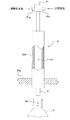
【図3】図2に示す各ステップでの工程を示す説明図である。
【図4】本発明に係る包装体製造装置の一実施形態を表す概略平面図である。
【図5】過酸化水素ガス生成装置の一例を表す部分切欠立面図である。
【図6】本発明に係る包装体製造装置の他の実施形態を表す概略平面図である。
【図7】過酸化水素ガス生成装置の他の一例を表す部分切欠立面図である。
【図8】本発明に係る包装体の他の実施形態を表す正面図である。
【図9】本発明に係る包装体製造装置におけるプロダクトラインの一例を示すブロック図である。
【図10】図9に示すプロダクトラインを接続した包装ラインの一例を示すブロック図である。
【図11】本発明に係る包装体製造装置における無菌チャンバー内殺菌装置を示す平面図である。
【図12】図11中、XII−XII線矢視断面図である。
【符号の説明】
【0097】
1,28…包装体、 2…ボトル、 2a…ボトルの口部、 3…キャップ、 5,6,7…ノズル、 8…キャッパー、 10…プリフォーム、 23,24,26,27…無菌チャンバー、 a…飲料、 b…過酸化水素のミスト又はガス、 c…加熱水、 76…導管、 77…帰還用の導管、 78…殺菌剤用スプレーノズル、 79…加熱水用スプレーノズル。
【発明を実施するための最良の形態】
【0098】
以下、本発明の最良の形態について図面に基づいて説明する。
【0099】
<実施の形態1>
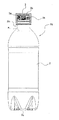
図1に示すように、この包装体1は容器であるボトル2と蓋であるキャップ3とを備える。ボトル2の口部2aには雄ネジ2bが形成され、キャップ3には雌ネジ3aが形成され、雌雄ネジ3a,2bの螺合によりボトル2の口部2aが密封される。
【0100】
ボトル2は、略試験管状のPET製プリフォーム(図示せず)をブロー成形することにより形成される。ボトル2は、PET製に限らずポリプロピレン、ポリエチレン等他の樹脂を用いることも可能である。プリフォームは、射出成形等により成形され、略試験管状の本体とボトル2におけると同様な口部2aとを備える。この口部2aにはプリフォームの成形と同時に雄ネジ2bが形成される。キャップ3はポリプロピレン等の樹脂を材料にして射出成形等により形成され、キャップ3の成形と同時に雌ネジ3aも形成される。
【0101】
ボトル2内は、内容物である液体飲料aの充填前に、細菌の芽胞の生存は許容するが細菌の栄養細胞、カビ及び酵母の生存は許容しないように殺菌剤と加熱水とで殺菌される。
【0102】
殺菌剤としては例えば過酸化水素が用いられる。この過酸化水素のミスト又はガスが生成され、ミスト又はガスがボトル2内に口部2aから導入される。このようにボトル2内が過酸化水素のミスト又はガスで殺菌されるので、ボトル2の内面がムラなく殺菌され、過酸化水素の使用量の低減化が可能となる。
【0103】
細菌の芽胞を殺菌する必要がないので、過酸化水素の使用量は少なくて済む。例えば、過酸化水素のミストの使用量は、5〜50μL(マイクロリットル)/ボトルである。過酸化水素のガスを使用する場合は、ガス濃度は1〜5mg/Lである。
【0104】
また、加熱水は65℃〜75℃の温度で供給され、5〜10L/minの流量でボトル2内に供給される。この加熱水がボトル2内に導入されることより、過酸化水素によって殺菌されにくいが熱には比較的弱い子嚢菌類等のカビ胞子が殺菌される。また、加熱水によりボトル2内が洗浄される結果、ボトル2内での過酸化水素の残留が防止される。
【0105】
ボトル2内には細菌の芽胞が生きたまま残留するが、細菌の芽胞の発芽を抑止しうる酸性度を有した殺菌処理済み飲料aがボトル2内に充填されることにより、飲料の変質、腐敗が防止される。この飲料の酸性度は、望ましくはpH4.6未満、より望ましくはpH4未満である。pH4.6〜pH4の飲料には、例えばトマトジュース、野菜ジュースがあり、pH4.6以下の飲料には、例えばレモンティー、オレンジジュース、乳性炭酸飲料、機能性飲料、炭酸入りレモンジュース、ぶどうジュース、果汁ジュースがある。
【0106】
また、この飲料aは常温でボトル2内に充填される。飲料aは予め加熱等により殺菌処理され、3℃〜40℃の常温まで冷まされた上でボトル2内に充填される。上述したようにボトル2内では細菌の芽胞の生存が許容されるので、従来のように飲料aを高温まで加熱した状態でボトル2に充填したり、ボトル2に充填後長時間保持したり、ボトル2に充填してキャップ3で閉じた包装体1を外部から加熱して殺菌したりする必要がない。従って、内容物である飲料aが変質し難く、また、飲料aの加熱、冷却に伴うボトル2の変形を考慮した減圧吸収パネルの形成や、ボトル2の口部2aの結晶化が不要になる。
【0107】
ボトル2の口部2aはキャップ3により閉じられ、ボトル2内に外部の空気や微生物が侵入しないように密封される。上述したように飲料aが常温で充填されるので、ボトル2の口部2aには熱による変形が生じない。これにより、ボトル2の口部2aにはキャップ3のリブ3bが正常に密着し、ボトル2が長期にわたり密封される。
【0108】
以上のように、ボトル2内では細菌の芽胞のみが残留し、この細菌の芽胞は内容物である飲料aの酸性によって発芽が抑止され静菌状態に保持されることから、飲料aは腐敗が防止され長期間にわたり正常に、しかも常温下で保存が可能となる。従って、この包装体1はいわゆる商業無菌製品となる。
【0109】
次に、上記包装体の製造方法について説明する。
【0110】
図2に示すように、内容物である飲料aが調合され(ステップS1)、加熱殺菌処理が行われる(ステップS2)。ここで、加熱温度は、飲料の酸性度がpH4.0の場合は90〜98℃程度、pH4.0〜4.6の場合は115〜122℃程度とされる。これにより、充填前の飲料a中の包装体内で発育しうる微生物が全て殺菌される。
【0111】
加熱殺菌処理された飲料aは、3℃〜40℃程度の常温まで冷却される(ステップS3)。この冷却は、加熱された飲料aを加熱前の飲料aとの間で熱交換することにより行うことができる。
【0112】
一方、プリフォームが用意され(ステップS6)、ブロー成形機によりプリフォームからボトル2がブロー成形される(ステップS7)。ボトル2はPETのほか、ポリプロピレン、ポリエチレン等他の樹脂で作ることもできる。
【0113】
ボトル2の内面に対して過酸化水素と加熱水による殺菌処理が行われ、ボトルの外面に対して過酸化水素による殺菌処理が行われる(ステップS8、S9)。上記プリフォームの供給(ステップS6)からボトル2の成形(ステップS7)を経てこの殺菌処理(ステップS8)に至る工程は時と場所を異にして別々に行うことも可能であるが、望ましくは連続して行われる。連続して行われることにより、包装体1を製造する場所まで容積の大きいボトル2の形態ではなく容積の格段に小さいプリフォームの形態で運搬することができ、それだけ運送費が減り包装体1の製造費が低減する。
【0114】
過酸化水素は後述する過酸化水素ガス生成装置4によりミスト化され、図3(A)に示すように、このミストがノズル5からボトル2に向かって吐出される。ノズル5の開口はボトル2の口部2aの開口に間隔を置いて臨み、ノズル5から吐出されるミストbがボトル2内に流入する。ミストbはボトル2の内面全体に付着し、ボトル2内の細菌の栄養細胞、カビ及び酵母を殺菌する。このボトル2内に供給する過酸化水素のミストbの量は、5〜50μL/ボトルであり、その殺菌力は細菌の栄養細胞、カビ及び酵母を殺菌するが、細菌の芽胞は殺菌しない程度とされる。これにより、過酸化水素の使用量の低減化が可能となる。
【0115】
また、図3(A)及び図4のごとく、ノズル5の近傍にはノズル5下のボトルを取り囲むようにトンネル29が配置され、このトンネル29内に高濃度の過酸化水素ミスト又はガスが滞留する。このため、過酸化水素のミスト又はガスbはボトル2の外面全体に付着し、ボトル2の外面に付着した細菌の栄養細胞、カビ及び酵母も殺菌する。このようにボトル2の外面も殺菌されることから、ボトル2の外面に付着した細菌の栄養細胞、カビ及び酵母のボトル2内への侵入と無菌充填機内への菌の持ち込みが防止され、ボトル2内に充填される飲料aの汚染が防止される。
【0116】
殺菌剤である過酸化水素により内外面が殺菌されたボトル2は、加熱水による殺菌に付される(ステップS9)。具体的には、図3(B)に示すように、65℃〜75℃の温度の加熱水が、5〜10L/minの流量でノズル6からボトル2内に供給される。その際望ましくはボトル2は倒立状態とされ、下向きになった口部2aからノズル6がボトル2の肩部まで挿入される。ボトル2内に流入した加熱水cはボトル2内を巡って口部2aからボトル2外に流出する。この加熱水cによって、過酸化水素によって損傷を受けた子嚢菌類等の一部のカビが殺菌される。また、この加熱水cによってボトル2内に残留した余剰の過酸化水素が洗い流され、ボトル2外に排出される。
【0117】
ここで、加熱水cによってボトル2の内面が殺菌される際、ボトル2の外面には過酸化水素のミストbが付着しているが、加熱水cの熱がボトル2の壁を外側へと伝わることにより過酸化水素によるボトル2の外面の殺菌効果が高められる。
【0118】
加熱水cにより殺菌にされたボトル2に、上記殺菌処理され常温まで冷やされた飲料aが常温で充填される(ステップS5)。充填時の飲料aの温度は3℃〜40℃程度である。上述したように、この包装体1の製造方法では細菌の芽胞を殺菌する必要がないので、飲料aを高温まで加熱した状態で充填したり、充填後長時間保持したり、包装体1を外部から加熱して殺菌したりする必要がない。従って、飲料aが変質し難く、また、飲料aの加熱、冷却に伴うボトル2の変形を考慮して減圧吸収パネルを設けたり、ボトル2の口部2aを結晶化させたりする必要がない。
【0119】
飲料aの充填は、具体的には図3(C)に示すように、ノズル7をボトル2の口部2aに臨ませ、ノズル7から飲料aを吐出させることによって行われる。上述したように、この飲料aの酸性度は、望ましくはpH4.6未満、より望ましくはpH4未満であり、トマトジュース、野菜ジュース、レモンティー、オレンジジュース、乳性炭酸飲料、機能性飲料、炭酸入りレモンジュース、ぶどうジュース、果汁ジュース等を充填することが可能である。すなわち、この製造方法によると、pH4.6以上の麦茶やミルク入り飲料を除いたほとんど全ての飲料の包装体を製造することができる。言うまでもなくコーラやサイダーなど動物又は植物の組成成分を含まず、炭酸ガス圧1.0kg/cm2(20℃)以上の炭酸飲料の包装体も製造可能である。
【0120】
飲料aの充填に際し、ボトル2の外面も予め殺菌処理されているので、飲料aと共に微生物がボトル2内に引き込まれることはない。飲料aの菌による汚染がより適正に防止される。
【0121】
飲料aが定量充填されたボトル2は、図3(D)に示すようにキャップ3で密封される(ステップS10)。キャップ3は予め多数集められ(ステップ11)、飲料aが充填されたボトル2に向かって列になって向かい、途中で過酸化水素のミストbがキャップ3の内外面に向かって吹き付けられて殺菌処理され(ステップ12)、しかる後ボトル2の口部2aにあてがわれ螺合せしめられる。
【0122】
キャップ3の殺菌方法としては、例えば特許第3778952号公報で開示される方法を採用することができる。
【0123】
なお、少なくとも上記常温充填(ステップ5)からキャッピング(ステップ10)に至る過程は無菌チャンバー等で囲まれた無菌の雰囲気内すなわち無菌の環境下で行われる。この無菌チャンバー内は、予め過酸化水素の噴霧、加熱水の放水等により、細菌の芽胞の生存は許容するが細菌の栄養細胞、カビ及び酵母の生存は許容しないように殺菌処理される。そして、殺菌処理後は無菌エアが常時無菌チャンバー外に向かって吹き出るように、無菌チャンバー内に陽圧の無菌エアが供給される。
【0124】
キャッピングされたボトル2は上記包装体1である製品となって製造工程から排出される(ステップ13)。
【0125】
次に、上述した包装体1の製造方法を実施するための製造装置の一例について説明する。
【0126】
図4に示すように、この製造装置は、上記PET製ボトル2を所定の搬送路に沿って搬送する手段を有する。
【0127】
搬送手段は、複数の各種ホイール11,12,13,14,15,16,17,18,19,20を次々と隣接するごとく水平に配置し、各ホイール11,12,13,14,15,16,17,18,19,20の周りに図示しないグリッパーを所定のピッチで多数配置することにより構成される。もちろん、これらのホイール11,12,13,14,15,16,17,18,19,20は適宜追加、削除が可能である。隣り合うホイールは互いに反対方向に同じ周速度で回転し、各ホイール11,12,13,14,15,16,17,18,19,20の外周でグリッパーが各ホイール11,12,13,14,15,16,17,18,19,20と同じ周速度で旋回する。搬送手段の搬送路は、各種ホイール11,12,13,14,15,16,17,18,19,20を接続することにより円弧の連続となって延び、この円弧の連続線上を多数のボトル2が所定の間隔で走行する。すなわち、ボトル2は上流側のホイールのグリッパーにより把持されてホイールと共に旋回し、下流側のホイールに到達するとそのホイールのグリッパーに掴み替えられ、以後下流側のホイールへと一定速度で順次送られる。
【0128】
グリッパーとその開閉機構は公知のものを使用するので、その詳細な説明は省略する。
【0129】
図4に示すように、上記搬送路に沿って、ボトル2内を殺菌剤である過酸化水素により殺菌する(図3(A)参照)第一の殺菌処理手段のノズル5と、ボトル2内に加熱水cを注入して殺菌する(図3(B)参照)第二の殺菌処理手段のノズル6と、内容物である飲料aを殺菌処理済みのボトル2内に常温で充填する(図3(C)参照)充填手段のノズル7と、ボトル2を蓋であるキャップ3で密封する(図3(D)参照)密封手段としてのキャッパー8とが順に配置される。
【0130】
また、ボトル2の外面を過酸化水素のミストbで殺菌する外面殺菌処理手段も上記搬送路に沿って設けられるが、この実施の形態1では上記第一の殺菌処理手段のノズル5がこの外面殺菌処理手段を兼ねている。
【0131】
第一の殺菌処理手段のノズル5等が設けられる第一のホイール11の上流側には導入コンベア11aが接続され、この導入コンベア11a上にはブロー成形機9が配置される。ブロー成形機9にはプリフォーム10が供給され、ブロー成形機9でプリフォーム10から成形されたボトル2が導入コンベア11aにより一定ピッチで第一のホイール11へと送られる。
【0132】
第一の殺菌処理手段のノズル5の設置数は一本でも複数本でもよい。このノズル5の先端における開口がボトル2の口部2aの開口に所定の間隔を置いて正対する。ノズル5の開口から吐出する過酸化水素のミストbが図3(A)に示すようにボトル2の口部2aからボトル2内へと流れ込む。
【0133】
また、第一のホイール11においてノズル5下をボトル2が通る箇所には、ボトル2を取り囲むようにトンネル29が設けられる。ノズル5の開口から吐出する過酸化水素のミストbの一部はトンネル29内に充満し、ボトル2の外面に付着してボトル2の外面を効率よく殺菌する。
【0134】
過酸化水素のミストbは、例えば図5に示す過酸化水素ガス生成装置4により生成される。この生成装置4は、殺菌剤である過酸化水素の水溶液を滴状にして供給する二流体スプレーである過酸化水素供給部21と、この過酸化水素供給部21から供給された過酸化水素の噴霧をその沸点以上の非分解温度以下に加熱して気化させる気化部22とを備える。過酸化水素供給部21は、過酸化水素供給路21a及び圧縮空気供給路21bからそれぞれ過酸化水素の水溶液と圧縮空気を導入して過酸化水素の水溶液を気化部22内に噴霧するようになっている。気化部22は内外壁間にヒータ22aを挟み込んだパイプであり、パイプ内に吹き込まれた過酸化水素の噴霧を加熱し気化させる。気化した過酸化水素のガスはノズル5からボトル2の口部2aに向って噴出する。気化した過酸化水素は、ノズル5を出てボトル2の近傍に至るまでの間に沸点以下の温度まで降下することにより、一部が凝縮し液化する。これにより、過酸化水素の気液混合体である微細なミストbが生成される。この過酸化水素の微細なミストbがノズル5から上記ボトル2の内部に吹き込まれ、ボトル2の内面の全体に付着する。ボトル2の内面に付着したミストbは結露し、高濃度の過酸化水素となって、ボトル2の内面を速やかに殺菌する。
【0135】
このミストbは上述したように、従来のアセプティック法におけるよりも供給量が少ない。このミストbにより、ボトル2内の細菌の栄養細胞、カビ及び酵母は殺菌されるが、細菌の芽胞は生きたまま残留する。
【0136】
上記第一の殺菌処理手段のノズル5を含むように、第一のホイール11の回りは第一の無菌チャンバー23に囲まれる。第一の無菌チャンバー23内はノズル5から吐出されるミストbで充満し、同じく第一の無菌チャンバー23内に供給される無菌エアと共に第一の無菌チャンバー23におけるボトル2の出入口から吹き出し、微生物を含んだ外気の侵入を阻止する。上記ノズル5はこの第一の無菌チャンバー23に連結部材23aで連結されることにより、この第一の無菌チャンバー23内の定位置に固定される。
【0137】
上記ノズル5から吐出されるミストbは、第一の無菌チャンバー23内において、図3(A)に示すように、トンネル29内に高濃度の過酸化水素ミストが滞留し、ボトル2外へも流れてボトル2の外面上に付着し或いは第一の無菌チャンバー23内を漂う細菌の栄養細胞、カビ及び酵母を殺菌する。
【0138】
第二のホイール12の外周に配置されるグリッパーは、図示しないが水平枢軸を介して第二のホイール12側に支持され、第二のホイール12の旋回軸を中心にして円弧状に湾曲するカムに接触することにより、第一のホイール11との接点からボトル2を受け取って進行すると、カムの案内により上下反転する。これにより、図3(B)に示すようにボトル2も上下反転し、その口部2aが下向きとなる。
【0139】
第二の殺菌処理手段のノズル6は、図3(B)に示すように、加熱水cを下向きになったボトル2内に供給するため上向きに一本又は複数本配置される。ノズル6は各グリッパーの真下にグリッパーと共に旋回運動するように設けられる。図示しないが、各ノズル2は各グリッパーの真下においてカム機構によって上下動しボトル2内に出入り可能である。また、第二の殺菌処理手段は、無菌の加熱水cをマニホルド、中空管等からノズル6に供給するようになっている。図3(B)に示すように、ノズル6から吹き出た加熱水cはボトル2内を巡った後、口部2aから流れ出る。各ボトル2の加熱水による殺菌は図4中ホイール12の回りの二点鎖線で示す領域内において行われる。
【0140】
この加熱水cは、芽胞の生残は許容するがカビ、酵母を滅菌することができる殺菌条件で過熱殺菌した後に65℃〜75℃の温度まで冷却されており、5〜10L/minの流量でノズル6から各ボトル2内に供給される。また、この加熱水はフィルタによる濾過滅菌法により除菌した後、熱交換器で昇温することにより作ることもできる。この加熱水cによって、過酸化水素によって損傷を受けた子嚢菌類等の一部のカビが殺菌される。また、この加熱水cによって、ボトル2内に残留した余剰の過酸化水素が洗い流され、ボトル2外に排出される。また、この加熱水cの熱によってボトル2の外面に付着した過酸化水素によるボトル2の外面の殺菌効果が高められる。
【0141】
図4に示すように、第二の殺菌処理手段のノズル6を含むように第二〜第四のホイール12,13,14の回りが第二の無菌チャンバー24により覆われる。この第二の無菌チャンバー24内にも陽圧の無菌エアが供給される。
【0142】
加熱水cで殺菌処理されたボトル2は、第二のホイール12から第三〜第五のホイール13,14,15を経て第六のホイール16へと受け渡される。この第六のホイール16の所定位置に充填機25が設置される。ボトル2はこの第六のホイール16のグリッパーに把持されて搬送されつつ充填機25で内容物である飲料aが充填される。充填機25は、図3(C)に示すように、ノズル7を有し、このノズル7から飲料aを所定量だけボトル2内に充填するようになっている。ノズル7は一本又は複数本設けることができる。
【0143】
充填時の飲料aの温度は3℃〜40℃程度の常温である。また、飲料aの酸性度は、望ましくはpH4.6未満、より望ましくはpH4未満であり、トマトジュース、野菜ジュース、レモンティー、オレンジジュース、乳性炭酸飲料、機能性飲料、炭酸入りレモンジュース、ぶどうジュース、果汁ジュース等が充填される。
【0144】
充填機25のノズル7を含むように第五のホイール15から第七のホイール17にわたる箇所が第三の無菌チャンバー26により囲まれる。この第三の無菌チャンバー26内にも陽圧の無菌エアが供給される。
【0145】
図4に示すように、第八のホイール18の所定位置に密封手段であるキャッパー8が設置される。飲料aが充填されたボトル2がキャッパー8に到達すると、図3(D)に示すように、ボトル2の口部2aにキャップ3が巻締められる。
【0146】
このキャッパー8を含むように第八〜第十のホイール18,19,20の回りが第四の無菌チャンバー27により覆われる。この第四の無菌チャンバー27内にも陽圧の無菌エアが供給される。
【0147】
キャッパー8によりキャップ3で閉じられたボトル2は、リジェクト用の第十のホイール20を経由して搬出用のコンベア20aから第四の無菌チャンバー27外に包装体1として搬出され出荷される。一方、充填、キャッピング等に支障のあるボトル2はリジェクト用のコンベア20bから別経路で第四の無菌チャンバー27外に搬出され、回収される。
【0148】
上記ノズル5から吐出されるミストbは、第一の無菌チャンバー23内で充満する。第一の無菌チャンバー23内には、ボトル2に付着し、或いはボトル2の走行に伴い発生する気流に乗って微生物が無菌チャンバー23,24,26,27内へと侵入する恐れがあるが、こうした微生物に対して無菌チャンバー23を漂う殺菌剤のミスト又はガスが高濃度の過酸化水素水となって凝結する。このため、無菌チャンバー23内に侵入した微生物は速やかにかつ確実に殺菌される。したがって、無菌チャンバー23,24,26,27内の無菌性は長期間高度に維持されることとなり、無菌性に優れた包装体の製造が可能となる。
【0149】
その他、第一〜第四の無菌チャンバー23,24,26,27には、チャンバー内殺菌装置が付設される。すべての無菌チャンバー23,24,26,27内は、包装体1の製造開始に先立ちこのチャンバー内殺菌装置により殺菌される。この殺菌は過酸化水素等の殺菌剤のスプレー、加熱水の噴射、放水等により行われ、細菌の芽胞は残留するが細菌の栄養細胞、カビ及び酵母は殺菌される程度に行われる。
【0150】
<実施の形態2>
図6に示すように、この実施の形態2では、実施の形態1の場合と異なり、導入コンベア11aとホイール12との間にホイール11b,11c,11dが配置され、これらホイール11b,11c,11dが第一の無菌チャンバー23内に収納されている。ボトル2は、導入コンベア11aからホイール11bを経てホイール11cに至り、ホイール11cの回りを走行しつつノズル5から過酸化水素のガスbを吹き込まれ、ホイール11dを経てホイール12に至り、ホイール12の回りを走行しつつ加熱水で殺菌されるようになっている。
【0151】
図7に示すように、ホイール11cは機台60上に起立する旋回軸61に水平に取り付けられ、旋回軸61を軸にして回転可能である。ホイール11cの盤面からは支柱61aが上方に伸び、支柱61aの上端に上記過酸化水素のガスbが流入するマニホルド62が固定される。マニホルド62の上部中央からは旋回軸61の軸心の延長線上で導管63が上方に伸び、この導管63が機台60に連結される支持部材64にベアリング65を介して保持される。これにより、マニホルド62はホイール11cと一体で旋回軸61の回りを回転可能である。
【0152】
また、ホイール11cの盤面からは他の支柱66が上方に伸び、この支柱66の上部にボトル2のホルダー68が取り付けられる。支柱66及びホルダー68は所定のピッチでホイール11bの回りに多数配置される。多数のホルダー68は支柱66を介してホイール11cに連結されるので、ホイール11cの回転と共に回転する。
【0153】
マニホルド62の回りからは各ホルダー68に向って過酸化水素のガスbの供給管67がそれぞれ伸び、各供給管67の先端に上記ノズル75が取り付けられる。ノズル75は上記支柱に固定され、その先端の開口がホルダー68に保持されたボトル2の口部2aに正対する。これにより、ホイール11cが回転すると、ノズル75はホルダー68に保持されたボトルと共に旋回軸61の回りを旋回し、過酸化水素のガスbをボトル2内に吹き込む。
【0154】
また、ホイール11bの周囲には、ホルダー68に保持されたボトル2の通り道を囲むようにトンネル29が設けられる。上記ノズル75から吐出されるガスbは、ボトル2の外側へも流れ、トンネル29内において高濃度の過酸化水素ミストとなって滞留し、ボトル2の外面上に付着し或いはトンネル29内を漂う細菌の栄養細胞、カビ及び酵母を殺菌する。
【0155】
上記マニホルド62の導管63の上端には、加熱管70がシール部材71を介して接続される。導管63はマニホルド62と一体で加熱管70に対して回転し、シール部材71が両管63,70の接続部からのガスbの漏れを防止する。加熱管70には図5に示した過酸化水素ガス生成装置4が複数基取り付けられ、各過酸化水素ガス生成装置4から過酸化水素のガスbが加熱管70内に供給される。過酸化水素ガス生成装置4の稼動する台数は、ボトル1の殺菌に必要とされるガスbの量等に応じて決定される。
【0156】
加熱管70の上流側にはブロア72、ULPA(Ultra Low Penetration Air Filter)フィルタ73及び電熱器74で構成される熱風供給装置が設けられる。ブロア72から引き込まれた空気がULPAフィルタ73で浄化され、電熱器74で所定温度まで加熱され、熱風hとなって加熱管70内に送られる。熱風hは過酸化水素の露点以上の例えば100℃以上の温度に加熱された無菌エアとされる。この熱風hは過酸化水素ガス生成装置4から送られる過酸化水素のガスbをマニホルド62へと搬送し、各供給管67を通ってノズル75からボトル1内へと噴出させ、或いはボトル5外に流出させる。
【0157】
ノズル75からボトル2内に過酸化水素のガスbが吹き込まれると、過酸化水素はミスト化してボトル2の内面の全体に付着する。ミストはボトル2の内面に付着して凝結し、高濃度の過酸化水素となってボトル2の内面を速やかに殺菌する。また、同様にボトル2の外面にも付着して凝結し、高濃度の過酸化水素となってボトル2の外面を速やかに殺菌する。
【0158】
この内外面を殺菌されたボトル2は、ホイール11dを経てホイール12へと送られ、実施の形態1の場合と同様にして、ノズル6から吹き出る加熱水cにより殺菌処理される。
【0159】
この実施の形態2においても、上記ノズル75から吐出されるミストbは、第一の無菌チャンバー23内に充満する。
【0160】
第一の無菌チャンバー23内には、ボトル2に付着し、或いはボトル2の走行に伴い発生する気流に乗って微生物が無菌チャンバー23,24,26,27内へと侵入する場合があるが、こうした微生物に対して無菌チャンバー23内を漂う殺菌剤のミスト又はガスが高濃度の過酸化水素水となって凝結する。このため、無菌チャンバー23内に侵入した微生物は速やかにかつ確実に殺菌される。したがって、無菌チャンバー23,24,26,27内の無菌性は長期間高度に維持されることとなり、無菌性に優れた包装体の製造が可能となる。
【0161】
その他、この実施の形態3において、実施の形態1におけるものと同一部分には同一の符号を付して示し、重複した説明を省略する。
【0162】
<実施の形態3>
図8に示すように、この実施の形態3における包装体28の容器は、底部2cがペタロイド型、あるいはシャンパン底型である耐圧ボトル2として形成される。このボトル2には、乳性炭酸飲料、果汁入炭酸飲料、果実着色炭酸飲料等のボトル2内をガスで加圧する性質の飲料aが充填される。
【0163】
図2に示すように、この飲料aは加熱殺菌(ステップ2)され、冷却され(ステップ3)た後に、炭酸ガスを圧入される(ステップ4)。そして、低温でペタロイド型、あるいはシャンパン底型のボトル2内に充填され(ステップ5)、以後実施の形態1の場合と同様な工程を経て包装体28とされる。
【0164】
その他、この実施の形態3において実施の形態1の部分と同じ部分には同一の符号を付して表すこととし重複した説明を省略する。
【実施例1】
【0165】
PET製ボトルの外面、内面の殺菌効果(LRV(Log Reduction value)=log(付着菌数/ln(総数/陰性数))について調べるため、試料A,B,C,D,を作成し、表1,2の結果を得た。
【0166】
【表1】

【0167】
【表2】
【0168】
ボトル外面の殺菌効果は黒カビの一種であるAspergillus niger NBRC6341、ボトル内面の殺菌効果は子嚢胞子の一種であるChaetomium globosum NBRC6347を指標菌とした。殺菌処理された外面用BI、及び内面用菌付けボトルはポテトデキストロース寒天培地、及びブドウ糖ペプトン培地で27℃のもと7日間培養することにより生残数を求めた。
【0169】
<実施の形態4>
実施の形態1〜3で使用されるプロダクトラインの殺菌方法及び装置について説明する。
【0170】
このプロダクトラインは、図10に例示する無菌の包装ラインに接続される。
【0171】
この無菌の包装ラインは、細菌の芽胞の生存は許容するが細菌の栄養細胞、カビ及び酵母の生存は許容しないように殺菌され、細菌の芽胞の発芽を抑止しうる酸性度を有した飲料である内容物を、図9に示すプロダクトラインから供給されることによって、容器であるPET(ポリエチレンテレフタレート)製ボトル内に充填しようというものである。
【0172】
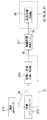
プロダクトラインは、図9に示すように、飲料の調合工程(S14)、調合された飲料の貯留工程(S15)、調合された飲料の加熱・冷却工程(S16)、加熱・冷却された飲料の無菌状態での貯留工程(S17)、常温充填工程(S5)の各工程を順に行うもので、飲料の調合工程(S14)を行うための調合タンクから常温充填工程(S5)を行うための充填機へと伸びる導管76を有する。
【0173】
この導管76上には、調合された飲料の貯留工程(S15)、調合された飲料の加熱・冷却工程(S16)、加熱・冷却された飲料の無菌状態での貯留工程(S17)の各工程に対応してバランスタンク、加熱・冷却機、無菌タンクが順に設けられる。
【0174】
なお、調合タンク、バランスタンク、加熱・冷却機、無菌タンク及び充填機の図示は省略する。
【0175】
調合タンクは、ボトル等の容器に充填する飲料を調合するためのタンクである。この調合タンクから次のバランスタンクに導管76が伸びている。
【0176】
バランスタンクは、調合タンクから来る飲料を貯留するためのタンクであり、バッファタンクとして機能するもので、必要に応じて設けられる。
【0177】
殺菌・冷却機は、具体的には超高温瞬間殺菌装置(UHT)であり、加熱と冷却を適宜切り替えて超高温瞬間殺菌装置内を通る流体を加熱又は冷却することが可能である。超高温瞬間殺菌装置は、飲料等の流体を高温であるが短時間で加熱することで、熱による飲料のダメージを最小限に抑えながら殺菌する装置である。したがって、飲料の風味、色等を保持した殺菌が可能である。この殺菌・冷却機とバランスタンクとの間は、飲料を殺菌・冷却機からバランスタンクへと戻すための破線で示す帰還用導管77で連結される。
【0178】
無菌タンクは、充填機の手前に設けられるバッファタンクであり、例えば充填機が一時的に停止したときに飲料を貯留するようになっている。
【0179】
充填機は、図3に示すようなノズル7を有し、このノズル7から飲料を所定量だけボトル内に充填するようになっている。この充填機の回りは図4又は図6に示したように無菌チャンバー26で囲まれ、ボトルに飲料を無菌状態で充填することができるように、無菌チャンバー26内は無菌状態に保持される。
【0180】
このプロダクトラインによって飲料は次のように処理された後に包装ラインへと供給される。
【0181】
飲料が調合タンクにおいて所望の割合で調合される(S14)。この調合された飲料はバランスタンク内に一時貯留され(S15)、その後、加熱・冷却機において加熱による殺菌と冷却水による冷却の各処理を施される(S16)。
【0182】
この加熱・冷却機による加熱温度は、飲料の酸性度がpH4.0の場合は90〜98℃程度、pH4.0〜4.6の場合は115〜122℃程度とされる。これにより、充填前の飲料中における包装後に包装体内で発育しうる微生物が全て殺菌される。すなわち、細菌の芽胞の生残は許容するが細菌の栄養細胞、カビ及び酵母の生存は許容しないように殺菌される。生残した細菌の芽胞は、上記酸性度の飲料内ではその発芽を抑止される。
【0183】
また、この加熱・冷却機による飲料の冷却温度は、2℃〜40℃程度の常温である。加熱・冷却機によって、飲料は所望の温度まで冷却される。
【0184】
常温まで冷却された飲料は、無菌タンク内に一旦貯留され(S17)、その後、充填機へと送られる(S5)。
【0185】
包装ラインは、図10に示すように、プリフォームの供給(S6)、ボトルの成形(S7)、ボトルの過酸化水素による殺菌(S8)、ボトルの加熱水による殺菌(S9)、飲料の常温充填(S5)、キャッピング(S10)、キャップの供給(S11)、キャップの殺菌(S12)、包装体の排出(S13)の各工程を含む構成となっている。
【0186】
なお、プリフォームの図示は省略するが、ボトル、キャップ及び包装体は図1又は図8に例示する形態となって現れる。
【0187】
容器であるボトルは、この包装ラインによって次のように処理された後に包装体とされる。
【0188】
まず、プリフォームが用意され(S6)、図示しないブロー成形機によりプリフォームからボトルがブロー成形される(S7)。ボトルはPETのほか、ポリプロピレン、ポリエチレン等他の樹脂で作ることもできる。
【0189】
ボトルの内外面に対して過酸化水素と加熱水による殺菌処理が行われる(S8、S9)。上記プリフォームの供給(S6)からボトルの成形(S7)を経て殺菌処理(S8)に至る工程は時と場所を異にして別々に行うことも可能であるが、望ましくは連続して行われる。
【0190】
過酸化水素は公知の過酸化水素ガス生成装置によりガス化又はミスト化され、このミスト又はガスがノズルからボトルに向かって吐出される。過酸化水素はボトルの内面全体に付着し、ボトル内の細菌の栄養細胞、カビ及び酵母を殺菌する。この過酸化水素の殺菌力は、細菌の栄養細胞、カビ及び酵母を殺菌するが、細菌の芽胞は殺菌しない程度とされる。これにより、過酸化水素の使用量の低減化が可能となる。
【0191】
また、過酸化水素のミスト又はガスはボトルの外面に付着した細菌の栄養細胞、カビ及び酵母も殺菌する。このようにボトルの外面も殺菌されることから、ボトルの外面に付着した細菌の栄養細胞、カビ及び酵母のボトル内への侵入が防止され、ボトル内に充填される飲料の汚染が防止される。
【0192】
過酸化水素により内外面が殺菌されたボトルは、加熱水による殺菌に付される(S9)。具体的には、65℃〜75℃の加熱水が、図示しないノズルからボトル内に供給される。ボトル内に流入した加熱水はボトル内を巡ってボトル外に流出する。この加熱水によって、過酸化水素により損傷を受けた子嚢菌類等の一部の耐薬剤性のあるカビが殺菌される。また、この加熱水によってボトル内に残留した余剰の過酸化水素が洗い流され、ボトル外に排出される。
【0193】
加熱水により殺菌されたボトルに、上記殺菌処理され常温まで冷却された飲料が常温で充填される(S5)。充填時の飲料の温度は2℃〜40℃程度である。
【0194】
飲料の充填は、具体的には図3に示したようにノズルをボトルの口部に臨ませ、ノズルから飲料を吐出させることによって行われる。上述したように、この飲料の酸性度は、望ましくはpH4.6未満、より望ましくはpH4未満であり、トマトジュース、野菜ジュース、レモンティー、オレンジジュース、乳性炭酸飲料、機能性飲料、炭酸入りレモンジュース、ぶどうジュース、果汁ジュース等である。
【0195】
飲料が定量充填されたボトルは、キャップで密封される(S10)。キャップは予め多数集められ(S11)、飲料が充填されたボトルに向かって列になって向かい、途中で過酸化水素のミスト又はガスがキャップの内外面に向かって吹き付けられて殺菌処理され(S12)、しかる後ボトルの口部にあてがわれネジ等の利用によって締め付けられる。
【0196】
キャップにより密封されたボトルは製品である包装体として包装ラインから排出される(S13)。
【0197】
上記プロダクトライン及び包装ライン中、少なくとも上記飲料の常温充填(S5)、ボトルの過酸化水素による殺菌(S8)、ボトルの加熱水による殺菌(S9)、キャッピング(S10)、キャップの殺菌(S12)の各工程は、各々無菌チャンバー23,24,26,27で囲まれた無菌の環境下で行われる。
【0198】
上記プロダクトラインと無菌の包装ラインは、包装体の製造に先立ち、包装体内に微生物が混入して繁殖することがないように、殺菌処理しておく必要がある。
【0199】
この殺菌処理は以下に述べるようにして行われる。
【0200】
包装ラインについては、図4又は図6に示した無菌チャンバー23,24,26,27内が殺菌処理される。この殺菌処理は例えば無菌チャンバー23,24,26,27内に過酸化水素を噴霧し、しかる後に加熱水を噴射すること等により、上記飲料及びボトルの殺菌効果と同様な殺菌効果を得ることができる程度に行われる。これにより、無菌チャンバー23,24,26,27内は、細菌の芽胞は生残するが、細菌の栄養細胞、カビ及び酵母は滅菌処理される。
【0201】
そして、この殺菌処理後は、無菌エアが無菌チャンバー23,24,26,27内から無菌チャンバー23,24,26,27外に向かって吹き出るように、陽圧の無菌エアが無菌チャンバー23,24,26,27内に常時供給される。
【0202】
プロダクトラインについては、次のように殺菌処理がなされる。
【0203】
まず、所定温度の加熱水が所定時間プロダクトラインに通される。加熱水の温度は、例えば85℃であり、通す時間は例えば30分間である。
【0204】
この加熱水が図9中工程(S14)〜工程(S5)に対応した調合タンク、バランスタンク、加熱・冷却機、無菌タンク、充填機の中を流れてそれらの内部と導管76,77とを加熱殺菌する。加熱水は加熱殺菌手段としての加熱・冷却機によって作られ、この加熱水が帰還用の導管77を通ってバランスタンクと加熱・冷却機との間を循環し、また調合タンク、無菌タンク、充填機へと送られる。
【0205】
この加熱水による加熱処理により、プロダクトライン内では、上記飲料及びボトルの殺菌効果と同様に、細菌の芽胞は生残するが、細菌の栄養細胞、カビ及び酵母は滅菌される。
【0206】
加熱水による加熱処理後、上記無菌チャンバー23,24,26,27内に供給される陽圧の無菌エアと同様な無菌エアがプロダクトライン内に常時供給され、プロダクトライン内が陽圧に保持される。
【0207】
なお、上記加熱水に代えて開放蒸気若しくは加圧蒸気を用いることも可能である。開放蒸気とは大気圧下で加圧されることなく供給される蒸気である。
【0208】
この後、常温の又は常温未満の無菌水がプロダクトラインに通されることによって、プロダクトライン内が常温まで冷却される。常温は例えば2℃から40℃であるが、飲料の性質等に応じて設定される。
【0209】
この無菌水に代えて常温の又は常温未満の飲料を流すことによっても同様な冷却効果を得ることができる。その場合は、プロダクトラインの殺菌工程を充填工程へと速やかに切り替えることができる。
【0210】
上記無菌水は、冷却手段としての上記加熱・冷却機を冷却用に切り替えることによって、上記加熱水を冷却することにより得ることができる。この冷却水を上記加熱水と同様にしてプロダクトライン内で流すことによって、プロダクトライン内を常温まで冷却することができる。
【0211】
かくて、酸性度がある程度高く芽胞の残留が許容されるが、ホットパック法には不適合な酸性飲料をボトル等の包装材内に充填するためのプロダクトラインを、短時間で簡易に殺菌することができることとなり、したがって、速やかに包装ラインの稼動が開始され、包装体の生産効率が高められる。
【0212】
<実施の形態5>
実施の形態1〜4において、無菌充填が行われる環境は、無菌環境保持手段によって、無菌状態に維持される。
【0213】
すなわち、図4又は図6に示すように、第一の殺菌処理手段、第二の殺菌処理手段、内容物充填手段、密封手段等は、無菌チャンバー23,24,26,27によって覆われ、外界から遮断される。そして、図11及び図12に示すように、無菌チャンバー23,24,26,27には、殺菌剤用スプレーノズル78と、加熱水用スプレーノズル79と、無菌エア供給装置80とが設けられる。
【0214】
殺菌剤用スプレーノズル78は、各無菌チャンバー23,24,26,27内の全域に殺菌剤が付着するように配置される。殺菌剤は過酸化水素が使用され、殺菌剤用スプレーノズル78としては過酸化水素の噴霧に圧縮空気を利用する二流体ノズルが用いられる。
【0215】
殺菌剤用スプレーノズル78から噴射された過酸化水素は各無菌チャンバー23,24,26,27内の全域に付着する。
【0216】
なお、殺菌剤としては過酸化水素に代えて過酢酸を用いることも可能である。また、過酢酸をスプレーして殺菌処理した後に、過酸化水素をスプレーして殺菌処理するようにしてもよい。
【0217】
加熱水用スプレーノズル79は、各無菌チャンバー23,24,26,27内の全域に加熱水が吹き付けられるように配置される。加熱水は上記各種実施の形態においてボトルの殺菌に使用される加熱水の供給源から供給することができ、80℃〜100℃に加熱された加熱水が各無菌チャンバー23,24,26,27内に噴射される。加熱水用スプレーノズルとしては、例えばスピンボールを用いたスプレーノズルが使用される。
【0218】
加熱水用スプレーノズル79から噴射された加熱水は各無菌チャンバー23,24,26,27内の全域に付着する。
【0219】
無菌エア供給装置80は二基用意され、その各ダクトが無菌チャンバー26の天井に接続される。各ダクトには、図12に示すように、水平部81と、この水平部81から無菌チャンバー26の天井に向かって垂下する垂直部82とが設けられる。水平部81内には、上流側から下流側に向かってブロア83、ヒーター84、ULPAフィルタ(Ultra Low Penetration Air Filter)85が順に設けられる。
【0220】
ブロア83の回転により、外気がダクト内に引き込まれ、この外気がヒーター84によって約100℃に加熱されてホットエアとなり、ULPAフィルタ85によって除塵、除菌された後無菌エアとなって無菌チャンバー26内に流入する。この無菌エアは無菌チャンバー26内から他の無菌チャンバー23,24,27へと流れ、全無菌チャンバー23,24,26,27内に滞留してこれらの内部を陽圧化し、無菌チャンバー23,27におけるボトル2の出入口等から流れ出る。これにより、無菌チャンバー23,24,26,27内への、塵埃、菌類等を含んだ外気の流入が防止される。
【0221】
上記ダクトの垂直部82には殺菌剤用スプレーノズル86が取り付けられる。包装体1の製造に先立ち、この殺菌剤用スプレーノズル86から噴射される過酸化水素によってULPAフィルタ85の表面とダクトの垂直部82内が殺菌処理される。
【0222】
次に、上記無菌環境保持手段の作用について説明する。
【0223】
無菌チャンバー23,24,26,27内は、無菌充填の開始に先立って殺菌処理される。
【0224】
各殺菌剤用スプレーノズル78,86から過酸化水素が噴射され、過酸化水素の噴霧が各無菌チャンバー23,24,26,27内の全域に付着する。この過酸化水素の噴霧によって、各無菌チャンバー23,24,26,27内における細菌の栄養細胞、カビ、酵母が殺菌される。また、ダクトの垂直部82内、ULPAフィルタ85の表面も同様に殺菌される。
【0225】
過酸化水素の噴霧が終了した後、無菌エア供給装置80のブロア83の作動によって、加熱された無菌エアが無菌チャンバー23,24,26,27内に供給される。この加熱された無菌エアによって各無菌チャンバー23,24,26,27内に付着した過酸化水素が乾燥され除去される。
【0226】
その後、加熱水用スプレーノズル79から加熱水が噴射され、無菌チャンバー23,24,26,27内の全域に吹き付けられる。これにより、上記過酸化水素によって損傷を受けた子嚢菌類の一部のカビが殺菌される。
【0227】
無菌エア供給装置80のダクトには垂直部82が設けられているので、スプレーされた加熱水はこの垂直部82の存在によってULPAフィルタ85への付着を阻止される。したがって、ULPAフィルタ85の加熱水による毀損が防止される。
【0228】
上記過酸化水素は所定の濃度のものが所定の流量で所定時間だけ供給され、上記加熱水も所定の温度のものが所定の流量で所定時間だけ供給される。
【0229】
かくて、無菌チャンバー23,24,26,27内は、細菌の芽胞の生残は許容するが細菌の栄養細胞、カビ及び酵母の生残は許容しない程度の無菌状態とされる。これは既述した飲料等の内容物やボトル2の内部と同程度の無菌状態である。
【0230】
そして、この無菌状態は、無菌エア供給装置80によって無菌エアが無菌チャンバー23,24,26,27内に常時供給されることによって維持される。
【0231】
このように無菌チャンバー23,24,26,27内が殺菌処理された後に、第一の殺菌処理手段、第二の殺菌処理手段、内容物充填手段、密封手段等が稼動し、無菌包装体1の製造が開始される。
【0232】
なお、本発明は上記実施の形態1〜5に限定されるものではなく、本発明の要旨の範囲内において種々変更可能である。例えば、上記実施の形態1〜5では、PET製ボトルを殺菌対象としたが、本発明はPET以外の材料、例えばポリプロピレン、蒸着PET、ポリエチレン、ガラスで出来たボトルについても適用可能である。また、ボトル以外の形態、例えばカップ状の容器についても適用可能である。
【0233】
また、上記実施の形態1〜5では殺菌剤として過酸化水素を使用したが、過酸化水素に代えて過酢酸系殺菌剤を使用することも可能であり、また、その場合は加熱水に限らず常温水を使用することも可能である。
【Technical field】
[0001]
The present invention relates to a package in which contents such as beverages are filled in a commercial aseptic manner in a container such as a bottle.manufacturing deviceAbout.
[Background]
[0002]
(1) According to the Food Sanitation Law, acidic beverages (pH <4) to which a predetermined carbon dioxide pressure is applied do not require sterilization, but when a plant or animal composition component is included, sterilization is performed regardless of the presence or absence of carbon dioxide pressure. Therefore, in the case of a carbonated beverage having a plant or animal composition and having a pH of less than 4.0 (for example, a milky carbonated beverage, a fruit juice carbonated beverage, a fruit-colored carbonated beverage), it is 10 at 65 ° C. It is necessary to heat for a minute.
[0003]
This sterilization is performed, for example, by filling an acidic beverage in a heat-resistant / pressure-resistant bottle and sealing it with a cap, and then applying a shower of heated water of about 65 ° C. to 75 ° C. from above the heat-resistant / pressure-resistant bottle. Thereby, the contents, the bottle and the cap are sterilized.
[0004]
(2) Moreover, when a drink is pH 4.0-4.6 on the Food Sanitation Law (for example, vegetable drinks, such as tomato juice and vegetable juice), it is necessary to heat at 85 degreeC for 30 minutes.
[0005]
For this sterilization, a sterilization method called a hot pack method is generally employed. In the hot pack method, for example, the beverage is heated to about 90 ° C to 140 ° C to sterilize the beverage itself, filled in a heat-resistant bottle at 85 ° C to 95 ° C to sterilize the inner surface of the bottle, and sealed with a cap. The bottle is tumbled to sterilize the inner surface of the cap, and cooled in stages with a path riser to form a package. By this hot pack method, not only beverages but also heat-resistant bottles and caps are sterilized.
[0006]
When the bottle is made of, for example, PET (polyethylene terephthalate), the bottle may be deformed when sterilized with heated water having a temperature higher than 85 ° C. In order to prevent the deformation of the bottle, a method is also proposed in which hot water of 65 to 85 ° C. is intermittently sprayed into the bottle to clean the inner surface of the bottle, and then an acidic beverage is filled at room temperature and sealed. (For example, refer to Patent Document 6).
[0007]
(3) In addition, when the beverage has a pH of 4.6 or higher according to the Food Sanitation Law (for example, tea beverages such as milk tea, tea beverages such as green tea, barley tea, and mixed tea), microorganisms that can grow are killed. It is required to sterilize by a method having sufficient efficacy.
[0008]
The aseptic method is employed for the production of such a beverage aseptic package. In this aseptic method, the bottle is run in a sterile environment, the bottle is preheated, the bottle is sterilized with a mist of hydrogen peroxide as a bactericide, the bottle is washed, and the sterilized beverage is put into a bottle at room temperature. Aseptic packaging is manufactured by filling and then sealing the bottle with a cap (see, for example, Patent Document 1).
[0009]
Moreover, in the said hot pack method, the path | route from the preparation tank of a drink which is a product line to the filling machine which packs a drink into a bottle is sterilized by the sterilization method according to the sterilization of the said drink itself prior to a filling operation.
[0010]
This product line sterilization is performed, for example, by circulating heated water at 85 ° C. in the product line piping for about 30 minutes.
[0011]
After circulating the heated water, the pipe is not cooled, but the beverage heated to a predetermined temperature is passed through the product line and filled into a bottle or the like, and the product line is maintained in a sterilized state by the heated beverage.
[0012]
Also in the aseptic method, the path from the beverage preparation tank, which is the product line, to the filling machine for filling the bottle with the beverage is sterilized by a sterilization method similar to the beverage sterilization prior to the filling operation.
[0013]
The product line sterilization may be performed by using, for example, hydrogen peroxide and steam together (see, for example, Patent Document 3). Generally, steam at 120 ° C. to 130 ° C. is provided in the pipe. For example, by passing for 20 to 30 minutes. Thereafter, aseptic air is sent into the pipe, cooled, and filling starts when the temperature drops to room temperature (about 2 ° C. to 40 ° C., depending on the contents).
[0014]
Further, in both the hot pack method and the aseptic method, the inside of the sterile chamber surrounding the sterile packaging apparatus is sterilized in advance before starting the filling operation (see, for example,
[0015]
The path from the sterilization of the bottle to the sealing with the cap through the filling of the beverage, etc. is covered with an aseptic chamber, but the inside of the aseptic chamber is also sterilized prior to the filling operation by a sterilization method similar to the sterilization of the beverage, the bottle, etc. Is done.
[0016]
As a conventional sterilization method for an aseptic chamber, a method in which peracetic acid is sprayed, sterile water is introduced, hot air is introduced, hydrogen peroxide is sprayed, and hot air is introduced in this order (for example, see Patent Document 2). A method of performing sterilization with acetic acid-based chemicals and cleaning with heated water in order (for example, refer to Patent Document 4), filling air with a sterilizing agent such as hydrogen peroxide or peracetic acid from the start of the filling operation A method (for example, refer to Patent Document 5) for blowing into a sterile chamber has been proposed.
[Patent Document 1] Japanese Patent Laid-Open No. 2001-39414
[Patent Document 2] Japanese Patent No. 3315918
[Patent Document 3] Japanese Patent Application Laid-Open No. 57-93061
[Patent Document 4] Japanese Unexamined Patent Application Publication No. 2008-168930
[Patent Document 5] JP-A-9-328113
[Patent Document 6] Japanese Patent No. 2844983
DISCLOSURE OF THE INVENTION
[Problems to be solved by the invention]
[0017]
According to the sterilization methods (1) and (2) above, vegetative cells of fungi, yeast and bacteria are sterilized in microorganisms, but bacterial spores survive without being sterilized. Most bacterial spores excluding some acidophilic bacteria are acidic beverages with a certain degree of acidity (for example, vegetable juice, tomato juice, lemon tea, orange juice, milky carbonated beverages with a pH of less than 4.6, functionality In beverages, carbonated lemon juice, grape juice, fruit juice juice), the bacteriostatic state is maintained without germination, so that the beverage is stored without decay.
[0018]
However, if a sterilization method in which the shower of heated water (1) is sprayed on a bottle or a hot pack sterilization method (2) is adopted for such a beverage, the bottle must be heat-resistant. That is, when the bottle is made of, for example, PET (polyethylene terephthalate), the mouth portion must be crystallized to prevent deformation due to heating so that the mouth portion of the bottle is not deformed by heat and does not leak. In addition, when a bottle is filled with a hot beverage and heat is released after the lid is wrapped, the bottle contracts due to reduced pressure. In order to absorb this amount of contraction, a reduced pressure absorption panel must be provided on the side and bottom of the bottle. Various processes for such heat countermeasures increase the price of the package.
[0019]
When heated water at a temperature that does not cause deformation in a PET (polyethylene terephthalate) bottle is used, such a problem seems to be solved. In this case, sterilization in the bottle depends on the temperature control of the heated water. May become insufficient. For example, molds with high heat resistance are difficult to sterilize with heated water at such a temperature and may survive. In addition, the sterilization process in the bottle, the filling process of the contents, the capping process, etc. are carried out in an aseptic environment covered with a sterile chamber. If it adheres or drifts into the air and enters the aseptic environment, surviving microorganisms may enter the bottle together with the contents and contaminate the package.
[0020]
According to the aseptic method of the above (3), it is possible to supply the bottle at a low price without requiring heat resistance to the bottle, but this aseptic method is not limited to mold, yeast, and bacterial vegetative cells, Since it is a sterilization method that kills all microorganisms up to the bacterial spore, the sterilization process is complicated and requires a large amount of utilities such as a sterilizing agent, heated water, and hot air. In addition, prior to the start of filling, the filling device and the chamber surrounding it must be sterilized up to the bacterial spore, which requires a bactericidal agent, heated water and complicated processes and equipment, and requires a long time until sterilization. Need time. Therefore, the aseptic method is unsuitable because the above-described acidic beverage having a certain degree of acidity and allowing the spore to remain is excessive facilities and processes.
[0021]
In addition, according to the sterilization method (2) above, vegetative cells of mold, yeast, and bacteria are sterilized in microorganisms in the product line, but the bacterial spores survive without being sterilized. These bacterial spores are acidic beverages with a certain degree of acidity (for example, vegetable juice having a pH of less than 4.6, tomato juice, lemon tea, orange juice, milky carbonated beverage, functional beverage, carbonated lemon juice, grape juice, fruit juice In the juice), the bacteriostatic state is maintained without germination, so that the beverage is stored without decaying, so that survival in the product line is allowed.
[0022]
However, in order to perform filling while maintaining the sterilized state in which the survival of only the spores is allowed, the contents such as beverages must be fed into the product line in a heated state. For this reason, the sterilization method (2) cannot be used for filling contents such as dairy products, for which heating is not desirable.
[0023]
According to the product line sterilization method according to (3) above, the pipe is heated to about 130 ° C. and then cooled to room temperature with sterile air. Therefore, there is a problem that the operation time of the aseptic filling machine is reduced.
[0024]
Moreover, the sterilization process in the aseptic chamber before the filling operation in the related art is performed according to the aseptic method (3) above. As described above, the Aseptic method is a sterilization method that kills all microorganisms, not only molds, yeasts, and bacterial vegetative cells, but also bacterial spores. A large amount is required, and a long time is required until sterilization. Therefore, the sterilization treatment in the aseptic chamber by the aseptic method is unsuitable because the above-described acidic beverage having a certain degree of acidity and allowing the spore to remain is excessive facilities and processes.
[0025]
Therefore, the present invention can appropriately store an acidic beverage having a certain degree of acidity and allowing spore retention without causing spoilage, and uses a highly heat-resistant container and expensive production equipment. It is an object of the present invention to provide means capable of aseptically filling and storing an acidic beverage at low cost.
[0026]
Another object of the present invention is to provide a means for easily sterilizing a product line used in aseptic filling in a shorter time.
[0027]
Another object of the present invention is to provide means that can easily sterilize the environment in an aseptic chamber for aseptic filling in a shorter time.
[Means for Solving the Problems]
[0028]
In order to solve the above problems, the present invention employs the following configuration.
[0029]
In addition, in order to make an understanding of this invention easy, the reference number of an accompanying drawing is attached in parenthesis, However, This invention is not limited to the form of illustration.
[0030]
[0031]
[0032]
[0033]
[0034]
[0035]
[0036]
[0037]
[0038]
[0039]
[0040]
[0041]
[0042]
[0043]
[0044]
[0045]
[0046]
[0047]
[0048]
[0049]
[0050]
[0051]
[0052]
[0053]
Claim1The invention according to the invention has a transport means for transporting the container (2) along a predetermined transport path, and sprays an aqueous solution of hydrogen peroxide into the vaporization section along the transport path, and the spray exceeds the boiling point. Obtained by heating below the non-decomposition temperature of the gas and evaporating it and ejecting from the vaporization part.In terms of 35% by mass hydrogen peroxide5-50 μL of hydrogen peroxideIs includedmistOr blow into the containerOr100% hydrogen peroxide in 1L1-5mgincludedFirst sterilization treatment means (5) for blowing hydrogen peroxide gas into the container;75℃ heated water 510Suppression of bacterial spores in the container sterilized by the second sterilization treatment means (6) supplied to the container at a flow rate of L / min, the first sterilization treatment means and the second sterilization treatment means Content filling means (7) for filling the container (2) with the sterilized content (a) having an acidity of less than pH 4.6 at room temperature or low temperature, and the container (2) with the lid (3 And the sealing means (8) to be sealed in order, and the portion from the first sterilization treatment means (5) to the sealing means (8) is covered by the aseptic chamber (23, 24, 26, 27). The path of the container (2) in the vicinity of the first sterilization treatment means (5) is surrounded by a tunnel (29), and the first sterilization treatment means (5) mists (b) or gas of the hydrogen peroxide. (B) blows on the inner and outer surfaces of the container (2) in the tunnel (29) An apparatus for manufacturing a package (1, 28), characterized in that so as to remain in the tunnel (29) together with the eclipsed.
[0054]
[0055]
Claim2As claimed in1In the manufacturing apparatus of the package (1, 28) according to
[0056]
Claim3As claimed in1The blow molding means (9) for molding the bottle (2) from the preform (10) immediately before the sterilization treatment means, in the manufacturing apparatus of the package (1, 28) described in 1. Can be provided.
[0057]
[0058]
[0059]
[0060]
[0061]
[0062]
[0063]
【Effect of the invention】
[0064]
According to the first aspect of the present invention, most of the microorganisms except the bacterial spores in the container (2) are sterilized with hydrogen peroxide, and some mold spores such as ascomycetes that are difficult to sterilize with hydrogen peroxide. Has been sterilized by the synergistic effect of hydrogen peroxide and heated water (c), and germs in the container (2) are prevented from germination due to the acidity of the contents (a) and remain in a bacteriostatic state. Therefore, the contents (a) can be stored for a long time without being spoiled. Further, since the bacterial spores are survived, sterilization treatment such as reducing the amount of hydrogen peroxide used can be simplified, and the manufacturing cost of the package can be reduced accordingly. Moreover, since the inside of the container (2) is sterilized with the heated water (c) and cleaned at the same time, the disinfectant (b) is prevented from remaining. In addition, since the contents (a) are filled at room temperature, it is possible to omit the reinforcing ribs, vacuum absorbing panels, etc. of the container (2), greatly increasing the amount of materials such as resin used to make the container (2). Can be reduced. Further, crystallization of the mouth (2a) of the container (2) is not necessary. Therefore, an inexpensive package (1, 28) can be obtained.
[0065]
Moreover, according to the invention which concerns on
[0066]
According to the invention which concerns on
[0067]
According to the invention which concerns on
[0068]
According to the invention of
[0069]
[0070]
[0071]
[0072]
According to the first aspect of the present invention, it is not necessary to sterilize bacterial spores, and the inside of the container (2) can be sterilized easily and quickly. In addition, most of the microorganisms in the container (2) excluding bacterial spores are sterilized with the bactericide (b), and other microorganisms that are not easily sterilized with the bactericide (b) such as ascomycete are sterilized with heated water (c). Therefore, in the container (2), germination is suppressed by the acidity of the content (a), and only bacterial spores that are maintained in a bacteriostatic state remain, thereby preventing the content (a) from being spoiled, The contents (a) can be stored normally at room temperature for a long period of time. Further, since the inside of the container (2) is sterilized with the heated water (c) and cleaned at the same time, the sterilizing agent (b) can be prevented from remaining. In addition, since the contents (a) are filled at room temperature, the reinforcing ribs, vacuum absorbing panels, etc. of the container (2) can be omitted, and the amount of materials such as resin used to make the container (2) can be reduced. Can do. Further, crystallization of the mouth (2a) of the container (2) is not necessary. Therefore, an inexpensive package (1, 28) can be obtained.
[0073]
According to the invention of
[0074]
According to the invention which concerns on
[0075]
According to the invention of
[0076]
[0077]
[0078]
[0079]
[0080]
[0081]
[0082]
Claim1The invention according to the invention has a conveying means for conveying the container (2) along a predetermined conveying path, and along this conveying path,An aqueous solution of hydrogen peroxide is sprayed into the vaporization part, this spray is heated to a non-decomposition temperature not lower than its boiling point and vaporized, and converted into 35% by mass hydrogen peroxide obtained by ejecting from the vaporization part. do it5-50 μL of hydrogen peroxideIs includedmistOr blow into the containerOr100% hydrogen peroxide in 1L1-5mgincludedFirst sterilization treatment means (5) for blowing hydrogen peroxide gas into the container;75℃ heated water 510Bacterial vegetative cells to the extent that bacterial spores survive by the second sterilization treatment means (6) supplied to the container at a flow rate of L / min, the first sterilization treatment means and the second sterilization treatment means In a container sterilized with mold and yeast, the sterilized content (a) having an acidity of less than pH 4.6 capable of inhibiting germination of the bacterial spore is placed in the container (2) at room temperature or low temperature. The filling means (7) for filling the contents and the sealing means (8) for sealing the container (2) with the lid (3) are arranged in order, and the sealing means (8) from the first sterilization processing means (5). ) Is covered with a sterilization chamber (23, 24, 26, 27), the passage of the container (2) in the vicinity of the first sterilization treatment means (5) is surrounded by a tunnel (29), The hydrogen peroxide mist (b) by the sterilization treatment means (5) Is an apparatus for producing a package (1, 28), characterized in that gas (b) is sprayed on the inner and outer surfaces of the container (2) in the tunnel (29) and stays in the tunnel (29). Therefore, it is not necessary to sterilize bacterial spores, and the inside of the manufacturing apparatus of the package (1, 28) and the aseptic chamber (23, 24, 26, 27) and the container (2) surrounding it can be simply and quickly. It is possible to sterilize, and thus the manufacturing apparatus of the package (1, 28) can be reduced in size and simplified.
[0083]
In addition, most of the microorganisms excluding bacterial spores in the container (2) are sterilized with hydrogen peroxide by the first sterilization means (5), and other microorganisms such as ascomycetes that are difficult to be sterilized by hydrogen peroxide Since the sterilization is effected by the synergistic effect of the first and second sterilization means (6), only the bacterial spores that remain in the bacteriostatic state are prevented from germination due to the acidity of the contents (a) in the container (2). Thus, the content (a) can be prevented from being spoiled and the content (a) can be normally stored for a long period of time.
[0084]
Moreover, since the inside of the container (2) is sterilized with the heated water (c) and cleaned at the same time, the residual hydrogen peroxide can be prevented.
[0085]
In addition, since the contents (a) are filled at room temperature, the reinforcing ribs, vacuum absorbing panels, etc. of the container (2) can be omitted, and the amount of materials such as resin used to make the container (2) can be reduced. Can do.
[0086]
Further, crystallization of the mouth (2a) of the container (2) is not necessary. Therefore, an inexpensive package (1, 28) can be manufactured.
[0087]
Furthermore, since the first sterilization treatment means (5) is covered with the sterilization chamber (23), the sterilization chamber (23) is filled with hydrogen peroxide mist or gas in a supersaturated state. Microorganisms that have entered the aseptic chamber (23) on the airflow generated by the container (2) attached to (2) or traveling are hydrogen peroxide mist or gas becomes high-concentration hydrogen peroxide water. It is sterilized quickly and reliably by setting. Therefore, the sterility in the sterilization chamber (23, 24, 26, 27) is maintained at a high level, and the packaging body excellent in sterility can be manufactured.
[0088]
Claim2As claimed in1In the manufacturing apparatus of the package (1, 28) according to
[0089]
Claim3As claimed in1The blow molding means (9) for molding the bottle (2) from the preform (10) immediately before the sterilization treatment means, in the manufacturing apparatus of the package (1, 28) described in 1. Is provided with blow molding means (9) on the upstream side of the packaging body (1,28) manufacturing apparatus, so that the preform is much smaller in volume than the bottle (2). (10) can be transported to the manufacturing apparatus of the package (1, 28), the transportation cost is reduced accordingly, and the manufacturing cost of the package (1, 28) is reduced.
[0090]
[0091]
[0092]
[0093]
[0094]
[0095]
[Brief description of the drawings]
[0096]
FIG. 1 is a front view illustrating an embodiment of a package according to the present invention.
[Figure 2]Packaging manufacturing methodOneExampleIt is a flowchart showing.
3 is an explanatory diagram showing a process in each step shown in FIG. 2; FIG.
FIG. 4 is a schematic plan view showing an embodiment of a packaging body manufacturing apparatus according to the present invention.
FIG. 5 is a partially cutaway elevation view showing an example of a hydrogen peroxide gas generator.
FIG. 6 is a schematic plan view showing another embodiment of the packaging body manufacturing apparatus according to the present invention.
FIG. 7 is a partially cutaway elevation view showing another example of the hydrogen peroxide gas generator.
FIG. 8 is a front view showing another embodiment of the package according to the present invention.
FIG. 9 is a block diagram showing an example of a product line in the package manufacturing apparatus according to the present invention.
10 is a block diagram showing an example of a packaging line connecting the product lines shown in FIG.
FIG. 11 is a plan view showing an aseptic chamber sterilization apparatus in the packaging body manufacturing apparatus according to the present invention.
FIG. 12 is a cross-sectional view taken along line XII-XII in FIG.
[Explanation of symbols]
[0097]
DESCRIPTION OF
BEST MODE FOR CARRYING OUT THE INVENTION
[0098]
The best mode of the present invention will be described below with reference to the drawings.
[0099]
<
As shown in FIG. 1, the
[0100]
The
[0101]
The
[0102]
For example, hydrogen peroxide is used as the disinfectant. The hydrogen peroxide mist or gas is generated, and the mist or gas is introduced into the
[0103]
Since there is no need to sterilize bacterial spores, less hydrogen peroxide is used. For example, the amount of hydrogen peroxide mist used is 5 to 50 μL (microliter) / bottle. When hydrogen peroxide gas is used, the gas concentration is 1 to 5 mg / L.
[0104]
The heated water is supplied at a temperature of 65 ° C. to 75 ° C. and supplied into the
[0105]
Bacterial spores remain alive in the
[0106]
The beverage a is filled in the
[0107]
The
[0108]
As described above, only the bacterial spore remains in the
[0109]
Next, the manufacturing method of the said package is demonstrated.
[0110]
As shown in FIG. 2, the beverage a which is a content is prepared (step S1), and a heat sterilization process is performed (step S2). Here, the heating temperature is about 90 to 98 ° C. when the acidity of the beverage is pH 4.0, and about 115 to 122 ° C. when the pH is 4.0 to 4.6. Thereby, all the microorganisms which can grow in the package in the beverage a before filling are sterilized.
[0111]
The heat-sterilized beverage a is cooled to a room temperature of about 3 ° C. to 40 ° C. (step S3). This cooling can be performed by exchanging heat between the heated beverage a and the beverage a before heating.
[0112]
On the other hand, a preform is prepared (step S6), and the
[0113]
The inner surface of the
[0114]
Hydrogen peroxide is misted by a hydrogen
[0115]
Further, as shown in FIGS. 3A and 4, a
[0116]
The
[0117]
Here, when the inner surface of the
[0118]
The
[0119]
Specifically, the beverage a is filled by causing the
[0120]
When the beverage a is filled, the outer surface of the
[0121]
The
[0122]
As a method for sterilizing the
[0123]
Note that at least the process from filling at normal temperature (step 5) to capping (step 10) is performed in a sterile atmosphere surrounded by a sterile chamber or the like, that is, in a sterile environment. The aseptic chamber is sterilized by spraying with hydrogen peroxide, discharging heated water, etc. in advance so as to allow the survival of bacterial spores but not the survival of bacterial vegetative cells, mold and yeast. After the sterilization treatment, positive pressure aseptic air is supplied into the aseptic chamber so that the aseptic air always blows out of the aseptic chamber.
[0124]
The capped
[0125]
Next, an example of the manufacturing apparatus for implementing the manufacturing method of the
[0126]
As shown in FIG. 4, this manufacturing apparatus has means for transporting the
[0127]
The conveying means arranges a plurality of
[0128]
Since the gripper and its opening / closing mechanism use known ones, detailed description thereof will be omitted.
[0129]
As shown in FIG. 4, the inside of the
[0130]
Further, an outer surface sterilizing means for sterilizing the outer surface of the
[0131]
An
[0132]
The number of
[0133]
Further, a
[0134]
The hydrogen peroxide mist b is generated by, for example, the hydrogen
[0135]
As described above, the amount of supply of the mist b is smaller than that in the conventional aseptic method. The mist b sterilizes the vegetative cells, fungi and yeast of the bacteria in the
[0136]
The
[0137]
As shown in FIG. 3A, the mist b discharged from the
[0138]
The gripper disposed on the outer periphery of the
[0139]
As shown in FIG. 3 (B), one or a plurality of
[0140]
This heated water c is allowed to survive in the spore, but is cooled to a temperature of 65 ° C. to 75 ° C. after being sterilized by heating under sterilization conditions capable of sterilizing mold and yeast, and has a flow rate of 5 to 10 L / min. Then, it is supplied from the
[0141]
As shown in FIG. 4, the second to
[0142]
The
[0143]
The temperature of the beverage a at the time of filling is a normal temperature of about 3 ° C to 40 ° C. Further, the acidity of the beverage a is desirably less than pH 4.6, more desirably less than
[0144]
A portion from the
[0145]
As shown in FIG. 4, the
[0146]
Around the eighth to
[0147]
The
[0148]
The mist b discharged from the
[0149]
In addition, the first to fourth
[0150]
<
As shown in FIG. 6, in the second embodiment, unlike the first embodiment, the
[0151]
As shown in FIG. 7, the
[0152]
Further, another column 66 extends upward from the surface of the
[0153]
From the periphery of the manifold 62, the hydrogen peroxide gas
[0154]
A
[0155]
A
[0156]
A hot air supply device including a
[0157]
When hydrogen peroxide gas b is blown into the
[0158]
The
[0159]
Also in the second embodiment, the mist b discharged from the nozzle 75 fills the first
[0160]
In the first
[0161]
In addition, in this
[0162]
<
As shown in FIG. 8, the container of the
[0163]
As shown in FIG. 2, this beverage a is heat-sterilized (step 2), cooled (step 3), and then injected with carbon dioxide (step 4). Then, it is filled into a petaloid-type or champagne bottom-
[0164]
In the third embodiment, the same parts as those of the first embodiment are denoted by the same reference numerals, and redundant description is omitted.
[Example 1]
[0165]
Samples A, B, C, and D were prepared in order to examine the bactericidal effect (LRV (Log Reduction value) = log (attached bacteria count / ln (total count / negative count))) on the outer and inner surfaces of the PET bottle.
[0166]
[Table 1]
[0167]
[Table 2]
[0168]
The bactericidal effect on the outer surface of the bottle is a kind of black moldAspergillus niger NBRC6341, the bactericidal effect on the inner surface of the bottle is a kind of ascosporeChaetomium globosum NBRC6347 was used as the indicator bacterium. The sterilized outer surface BI and inner surface bacteria-attached bottles were cultured in potato dextrose agar medium and glucose peptone medium at 27 ° C. for 7 days to determine the survival number.
[0169]
<
The product line sterilization method and apparatus used in the first to third embodiments will be described.
[0170]
This product line is connected to a sterile packaging line illustrated in FIG.
[0171]
This sterile packaging line is a beverage that has been sterilized to allow bacterial spore survival but not bacterial vegetative cells, mold and yeast, and has an acidity that can inhibit germination of bacterial spores. A certain content is supplied from the product line shown in FIG. 9 to fill a PET (polyethylene terephthalate) bottle as a container.
[0172]
As shown in FIG. 9, the product line includes a beverage preparation step (S14), a prepared beverage storage step (S15), a prepared beverage heating / cooling step (S16), and a heated / cooled beverage The aseptic storage step (S17) and the normal temperature filling step (S5) are sequentially performed, and the filling for performing the normal temperature filling step (S5) from the preparation tank for performing the beverage preparation step (S14). It has a
[0173]
On the
[0174]
In addition, illustration of a mixing tank, a balance tank, a heating / cooling machine, an aseptic tank, and a filling machine is omitted.
[0175]
The preparation tank is a tank for preparing a beverage to be filled in a container such as a bottle. A
[0176]
The balance tank is a tank for storing beverages coming from the blending tank, functions as a buffer tank, and is provided as necessary.
[0177]
The sterilizer / cooler is specifically an ultra-high temperature instant sterilizer (UHT), and can heat or cool a fluid passing through the ultra-high temperature instant sterilizer by appropriately switching between heating and cooling. An ultra-high temperature instant sterilization apparatus is an apparatus that sterilizes a beverage or the like at a high temperature but in a short time while minimizing damage to the beverage due to heat. Therefore, sterilization that retains the flavor, color, etc. of the beverage is possible. The sterilizer / cooler and the balance tank are connected by a
[0178]
The aseptic tank is a buffer tank provided in front of the filling machine, and stores beverages when the filling machine is temporarily stopped, for example.
[0179]
The filling machine has a
[0180]
With this product line, the beverage is processed as follows and then supplied to the packaging line.
[0181]
The beverage is prepared at a desired ratio in the preparation tank (S14). The blended beverage is temporarily stored in the balance tank (S15), and then subjected to sterilization by heating and cooling by cooling water in a heating / cooling machine (S16).
[0182]
The heating temperature by this heating / cooling machine is about 90 to 98 ° C. when the acidity of the beverage is pH 4.0, and about 115 to 122 ° C. when the pH is 4.0 to 4.6. Thereby, all microorganisms that can grow in the package after packaging in the beverage before filling are sterilized. That is, it is sterilized so as to allow the survival of bacterial spores but not the survival of bacterial vegetative cells, fungi and yeast. Surviving bacterial spores are inhibited from germinating in the acidic beverage.
[0183]
Moreover, the cooling temperature of the drink by this heating / cooling machine is a room temperature of about 2 ° C. to 40 ° C. The beverage is cooled to a desired temperature by the heating / cooling machine.
[0184]
The beverage cooled to room temperature is temporarily stored in a sterile tank (S17) and then sent to the filling machine (S5).
[0185]
As shown in FIG. 10, the packaging line consists of preform supply (S6), bottle molding (S7), bottle sterilization with hydrogen peroxide (S8), bottle sterilization with heated water (S9), and room temperature of the beverage. The process includes filling (S5), capping (S10), cap supply (S11), cap sterilization (S12), and package discharge (S13).
[0186]
In addition, although illustration of a preform is abbreviate | omitted, a bottle, a cap, and a package appear in the form illustrated in FIG. 1 or FIG.
[0187]
The bottle which is a container is processed as follows by this packaging line, and is made into a package.
[0188]
First, a preform is prepared (S6), and a bottle is blow-molded from the preform by a blow molding machine (not shown) (S7). The bottle can be made of other resins such as polypropylene and polyethylene in addition to PET.
[0189]
The inner and outer surfaces of the bottle are sterilized with hydrogen peroxide and heated water (S8, S9). The steps from the preform supply (S6) to the bottle sterilization (S8) through the bottle molding (S7) can be performed separately at different times and places, but are preferably performed continuously. .
[0190]
Hydrogen peroxide is gasified or misted by a known hydrogen peroxide gas generator, and the mist or gas is discharged from the nozzle toward the bottle. Hydrogen peroxide adheres to the entire inner surface of the bottle and sterilizes the vegetative cells, molds and yeast of the bacteria in the bottle. The sterilizing power of hydrogen peroxide is such that it sterilizes bacterial vegetative cells, fungi and yeast, but does not sterilize bacterial spores. Thereby, the usage-amount of hydrogen peroxide can be reduced.
[0191]
The hydrogen peroxide mist or gas also sterilizes bacterial vegetative cells, molds and yeast attached to the outer surface of the bottle. Since the outer surface of the bottle is also sterilized in this way, invasion of vegetative cells, mold and yeast of bacteria attached to the outer surface of the bottle into the bottle is prevented, and contamination of the beverage filled in the bottle is prevented. .
[0192]
The bottle whose inner and outer surfaces are sterilized with hydrogen peroxide is subjected to sterilization with heated water (S9). Specifically, heated water at 65 ° C. to 75 ° C. is supplied into the bottle from a nozzle (not shown). The heated water that has flowed into the bottle flows out of the bottle around the bottle. This heated water sterilizes some chemical resistant molds such as ascomycetes damaged by hydrogen peroxide. In addition, excess hydrogen peroxide remaining in the bottle is washed away by the heated water and discharged out of the bottle.
[0193]
The bottle sterilized with heated water is filled with the beverage that has been sterilized and cooled to room temperature (S5). The temperature of the beverage at the time of filling is about 2 ° C to 40 ° C.
[0194]
Specifically, as shown in FIG. 3, the beverage is filled by causing the nozzle to face the mouth of the bottle and discharging the beverage from the nozzle. As mentioned above, the acidity of this beverage is preferably less than pH 4.6, more preferably less than
[0195]
The bottle filled with the beverage is sealed with a cap (S10). A large number of caps are collected in advance (S11), and are lined up toward bottles filled with beverages, and hydrogen peroxide mist or gas is sprayed toward the inner and outer surfaces of the caps on the way to be sterilized (S12). ) After that, it is applied to the mouth of the bottle and tightened by using a screw or the like.
[0196]
The bottle sealed with the cap is discharged from the packaging line as a package that is a product (S13).
[0197]
In the product line and packaging line, at least the above-mentioned beverage is filled at room temperature (S5), the bottle is sterilized with hydrogen peroxide (S8), the bottle is sterilized with heated water (S9), the capping (S10), and the cap is sterilized (S12). Each of these steps is performed in a sterile environment surrounded by
[0198]
Prior to the production of the package, the product line and the aseptic packaging line need to be sterilized so that microorganisms are not mixed and propagated in the package.
[0199]
This sterilization treatment is performed as described below.
[0200]
As for the packaging line, the inside of the
[0201]
Then, after this sterilization treatment, the positive pressure sterile air is blown out of the
[0202]
The product line is sterilized as follows.
[0203]
First, heated water at a predetermined temperature is passed through the product line for a predetermined time. The temperature of the heated water is, for example, 85 ° C., and the passing time is, for example, 30 minutes.
[0204]
The heated water flows through the blending tank, balance tank, heating / cooling machine, aseptic tank, and filling machine corresponding to steps (S14) to (S5) in FIG. Sterilize by heating. The heated water is produced by a heating / cooling machine as a heat sterilization means, and this heating water circulates between the balance tank and the heating / cooling machine through a
[0205]
By this heat treatment with heated water, bacterial spores remain in the product line, but the bacterial vegetative cells, fungi and yeast are sterilized in the same manner as the sterilizing effect of the beverage and bottle.
[0206]
After the heat treatment with heated water, aseptic air similar to the positive-pressure aseptic air supplied into the
[0207]
It is also possible to use open steam or pressurized steam instead of the heated water. Open steam is steam supplied without being pressurized under atmospheric pressure.
[0208]
Thereafter, sterile water at room temperature or below room temperature is passed through the product line to cool the inside of the product line to room temperature. The normal temperature is, for example, 2 ° C. to 40 ° C., but is set according to the nature of the beverage.
[0209]
The same cooling effect can be obtained by flowing a beverage at room temperature or below room temperature instead of this sterile water. In that case, the sterilization process of the product line can be quickly switched to the filling process.
[0210]
The aseptic water can be obtained by cooling the heated water by switching the heating / cooling machine as a cooling means to cooling. By flowing this cooling water in the product line in the same manner as the heating water, the inside of the product line can be cooled to room temperature.
[0211]
Thus, it is possible to easily sterilize a product line for filling a packaging material such as a bottle with an acidic beverage that has a high acidity to a certain extent but is not compatible with the hot pack method in a short time. Therefore, the operation of the packaging line is started quickly, and the production efficiency of the package is increased.
[0212]
<
In the first to fourth embodiments, the environment in which aseptic filling is performed is maintained in a sterile state by the sterile environment holding means.
[0213]
That is, as shown in FIG. 4 or FIG. 6, the first sterilization processing means, the second sterilization processing means, the content filling means, the sealing means, etc. are covered by the
[0214]
The sterilizing
[0215]
Hydrogen peroxide sprayed from the sterilizing
[0216]
In addition, it is also possible to use peracetic acid as a disinfectant instead of hydrogen peroxide. Further, after sterilizing by spraying peracetic acid, it may be sterilized by spraying hydrogen peroxide.
[0217]
The heated
[0218]
The heated water sprayed from the heated
[0219]
Two aseptic
[0220]
Due to the rotation of the
[0221]
A
[0222]
Next, the operation of the aseptic environment maintaining means will be described.
[0223]
The
[0224]
Hydrogen peroxide is sprayed from the
[0225]
After the spraying of hydrogen peroxide is completed, heated aseptic air is supplied into the
[0226]
Thereafter, heated water is sprayed from the heated
[0227]
Since the
[0228]
The hydrogen peroxide having a predetermined concentration is supplied at a predetermined flow rate for a predetermined time, and the heating water is also supplied at a predetermined temperature at a predetermined flow rate for a predetermined time.
[0229]
Thus, the inside of the
[0230]
This aseptic state is maintained by constantly supplying aseptic air into the
[0231]
After the inside of the
[0232]
In addition, this invention is not limited to the said Embodiment 1-5, A various change is possible within the range of the summary of this invention. For example, in
[0233]
In
Claims (3)
Priority Applications (1)
| Application Number | Priority Date | Filing Date | Title |
|---|---|---|---|
| JP2009531193A JP5739101B2 (en) | 2007-09-03 | 2008-08-26 | Packaging manufacturing equipment |
Applications Claiming Priority (6)
| Application Number | Priority Date | Filing Date | Title |
|---|---|---|---|
| JP2007228104 | 2007-09-03 | ||
| JP2007228104 | 2007-09-03 | ||
| JP2008127010 | 2008-05-14 | ||
| JP2008127010 | 2008-05-14 | ||
| PCT/JP2008/065172 WO2009031436A1 (en) | 2007-09-03 | 2008-08-26 | Packed product and method and apparatus for producing the same |
| JP2009531193A JP5739101B2 (en) | 2007-09-03 | 2008-08-26 | Packaging manufacturing equipment |
Related Child Applications (2)
| Application Number | Title | Priority Date | Filing Date |
|---|---|---|---|
| JP2013132465A Division JP5686160B2 (en) | 2007-09-03 | 2013-06-25 | Method and apparatus for manufacturing package |
| JP2013132466A Division JP5686161B2 (en) | 2007-09-03 | 2013-06-25 | Method and apparatus for aseptic filling of beverages |
Publications (2)
| Publication Number | Publication Date |
|---|---|
| JPWO2009031436A1 JPWO2009031436A1 (en) | 2010-12-09 |
| JP5739101B2 true JP5739101B2 (en) | 2015-06-24 |
Family
ID=40428756
Family Applications (6)
| Application Number | Title | Priority Date | Filing Date |
|---|---|---|---|
| JP2009531193A Active JP5739101B2 (en) | 2007-09-03 | 2008-08-26 | Packaging manufacturing equipment |
| JP2013132465A Active JP5686160B2 (en) | 2007-09-03 | 2013-06-25 | Method and apparatus for manufacturing package |
| JP2013132466A Active JP5686161B2 (en) | 2007-09-03 | 2013-06-25 | Method and apparatus for aseptic filling of beverages |
| JP2015011152A Active JP6044652B2 (en) | 2007-09-03 | 2015-01-23 | Method and apparatus for manufacturing package |
| JP2015011151A Active JP5910765B2 (en) | 2007-09-03 | 2015-01-23 | Method and apparatus for aseptic filling of beverages |
| JP2015011149A Active JP6044651B2 (en) | 2007-09-03 | 2015-01-23 | Method and apparatus for manufacturing package |
Family Applications After (5)
| Application Number | Title | Priority Date | Filing Date |
|---|---|---|---|
| JP2013132465A Active JP5686160B2 (en) | 2007-09-03 | 2013-06-25 | Method and apparatus for manufacturing package |
| JP2013132466A Active JP5686161B2 (en) | 2007-09-03 | 2013-06-25 | Method and apparatus for aseptic filling of beverages |
| JP2015011152A Active JP6044652B2 (en) | 2007-09-03 | 2015-01-23 | Method and apparatus for manufacturing package |
| JP2015011151A Active JP5910765B2 (en) | 2007-09-03 | 2015-01-23 | Method and apparatus for aseptic filling of beverages |
| JP2015011149A Active JP6044651B2 (en) | 2007-09-03 | 2015-01-23 | Method and apparatus for manufacturing package |
Country Status (5)
| Country | Link |
|---|---|
| US (1) | US20100170867A1 (en) |
| JP (6) | JP5739101B2 (en) |
| KR (1) | KR20100051064A (en) |
| CN (1) | CN101795940B (en) |
| WO (1) | WO2009031436A1 (en) |
Families Citing this family (52)
| Publication number | Priority date | Publication date | Assignee | Title |
|---|---|---|---|---|
| EP2657183B1 (en) | 2008-05-20 | 2016-04-06 | Dai Nippon Printing Co., Ltd. | Beverage filling method |
| DE102009041215A1 (en) * | 2009-09-11 | 2011-03-24 | Krones Ag | Method and apparatus for stretch blow molding or blow molding and filling sterile containers |
| JP2011178402A (en) * | 2010-02-26 | 2011-09-15 | Dainippon Printing Co Ltd | Method and apparatus for filling acid beverage |
| EP2575768B1 (en) | 2010-05-24 | 2017-12-13 | Swedish Oat Fiber AB | Aqueous dispersion comprising galactolipids and method for production thereof |
| DE102011107772A1 (en) * | 2011-07-15 | 2013-01-17 | Krones Aktiengesellschaft | Method and device for producing beverage containers filled with liquids |
| JP5388155B2 (en) * | 2011-08-31 | 2014-01-15 | 株式会社日幸製作所 | Method for producing hydrogen water filled product |
| WO2013137321A1 (en) * | 2012-03-14 | 2013-09-19 | 大日本印刷株式会社 | Preform sterilization method and device |
| DE102012206716A1 (en) * | 2012-04-24 | 2013-10-24 | Krones Ag | FILLING OF COOLED PRODUCTS |
| JP5983222B2 (en) * | 2012-09-13 | 2016-08-31 | 大日本印刷株式会社 | Cell culture method and apparatus |
| CN104718151B (en) * | 2012-11-16 | 2016-08-17 | 大日本印刷株式会社 | The purification method of beverage filling device |
| ITPR20130017A1 (en) * | 2013-03-11 | 2014-09-12 | Gea Procomac Spa | CLOSING TREATMENT SYSTEM FOR CONTAINERS USING A STERILIZING SUBSTANCE |
| JP5582213B1 (en) * | 2013-03-28 | 2014-09-03 | 大日本印刷株式会社 | Filler purification method and apparatus |
| CN103231908B (en) * | 2013-04-26 | 2015-03-11 | 广东粤东机械实业有限公司 | Ultra-clean prefabricated cup filling machine |
| JP6747490B2 (en) * | 2013-11-14 | 2020-08-26 | 大日本印刷株式会社 | Preform sterilization method and device |
| JP6439921B2 (en) | 2013-11-14 | 2018-12-19 | 大日本印刷株式会社 | Bottle sterilization method and apparatus |
| US10308493B2 (en) | 2013-12-25 | 2019-06-04 | Dai Nippon Printing Co., Ltd. | Drink filling system |
| JP2015123964A (en) * | 2013-12-25 | 2015-07-06 | 大日本印刷株式会社 | Preform sterilization method and device |
| JP6651696B2 (en) * | 2014-02-12 | 2020-02-19 | 東洋製罐株式会社 | Container sterilization method and device |
| CN105939936B (en) * | 2014-02-12 | 2018-12-04 | 东洋制罐株式会社 | The method for disinfection and device of container |
| WO2015137480A1 (en) * | 2014-03-14 | 2015-09-17 | 大日本印刷株式会社 | Method and device for sterilizing container |
| JP6344948B2 (en) * | 2014-03-31 | 2018-06-20 | パナソニック株式会社 | Sterilization component removal device, sterilization device, sterilization environment maintenance system, and sterilization component removal method |
| CN106458554A (en) * | 2014-06-09 | 2017-02-22 | 东洋制罐集团控股株式会社 | Method and system for aseptic filling of beverage |
| JP2014221671A (en) * | 2014-07-31 | 2014-11-27 | 大日本印刷株式会社 | Method and apparatus for filling acid beverage |
| JP6627767B2 (en) * | 2014-09-25 | 2020-01-08 | 大日本印刷株式会社 | Carbonated beverage filling method and apparatus |
| JP5920433B2 (en) | 2014-09-25 | 2016-05-18 | 大日本印刷株式会社 | Method and apparatus for sterilizing filling nozzle |
| JP2016088579A (en) * | 2014-11-06 | 2016-05-23 | 澁谷工業株式会社 | Article processing system |
| JP6565171B2 (en) * | 2014-11-14 | 2019-08-28 | 澁谷工業株式会社 | Container transfer control device |
| CN108290729B (en) | 2015-12-22 | 2020-10-09 | 大日本印刷株式会社 | Sterilization conversion method and product filling device |
| CN105668481B (en) * | 2016-03-22 | 2017-12-26 | 新昌县新宏力铝业有限公司 | A kind of sterilizable steam generation pharmaceutical device |
| JP6540740B2 (en) * | 2016-04-07 | 2019-07-10 | 大日本印刷株式会社 | Method for cleaning and sterilizing beverage filling equipment |
| JP7062352B2 (en) * | 2016-04-28 | 2022-05-06 | 大日本印刷株式会社 | Plastic bottles, fillers, and methods for manufacturing fillers |
| DE102016113673A1 (en) * | 2016-07-25 | 2018-01-25 | Friedrich Fischer | Dosierspendersystem |
| JP6330876B2 (en) * | 2016-09-26 | 2018-05-30 | 大日本印刷株式会社 | Aseptic filling machine and aseptic filling method |
| US11261072B2 (en) | 2016-09-26 | 2022-03-01 | Dai Nippon Printing Co., Ltd. | Aseptic filling machine and aseptic filling method |
| JP6292275B1 (en) * | 2016-10-18 | 2018-03-14 | 大日本印刷株式会社 | Preform heating apparatus and heating method |
| EP3827964B1 (en) * | 2016-09-28 | 2023-08-23 | Dai Nippon Printing Co., Ltd. | Aseptic blow molding machine and aseptic blow molding method |
| JP6517177B2 (en) * | 2016-09-30 | 2019-05-22 | 大日本印刷株式会社 | Sterile carbonated beverage filling system and sterile carbonated beverage filling method |
| US10479668B2 (en) * | 2016-11-08 | 2019-11-19 | Pepsico, Inc. | Ambient filling system and method |
| DE102016125027A1 (en) * | 2016-12-20 | 2018-06-21 | Krones Ag | Device for treating system components and / or packaging with vaporized hydrogen peroxide |
| JP6380572B2 (en) * | 2017-02-20 | 2018-08-29 | 大日本印刷株式会社 | Trouble recovery method and aseptic filling machine for aseptic filling machine |
| JP6956495B2 (en) * | 2017-02-28 | 2021-11-02 | サントリーホールディングス株式会社 | Filling method and filling equipment |
| JP6548091B2 (en) * | 2017-03-28 | 2019-07-24 | 大日本印刷株式会社 | Method of verifying content filling system and content filling system |
| JP6519607B2 (en) * | 2017-06-09 | 2019-05-29 | 大日本印刷株式会社 | Method and apparatus for sterilizing filling nozzle |
| JP6521141B2 (en) * | 2018-04-25 | 2019-05-29 | 大日本印刷株式会社 | Aseptic filling machine and aseptic filling method |
| JP6516113B2 (en) * | 2018-04-25 | 2019-05-22 | 大日本印刷株式会社 | Aseptic filling machine and aseptic filling method |
| JP6645538B2 (en) * | 2018-06-29 | 2020-02-14 | 大日本印刷株式会社 | Aseptic carbonated beverage filling system and aseptic carbonated beverage filling method |
| JP6927359B2 (en) * | 2018-08-31 | 2021-08-25 | 大日本印刷株式会社 | Aseptic filling machine and its purification method |
| JP6663137B1 (en) * | 2018-10-04 | 2020-03-11 | 大日本印刷株式会社 | Container outer surface sterilizer and nozzle for container outer surface sterilization |
| JP7106422B2 (en) * | 2018-10-23 | 2022-07-26 | アサヒ飲料株式会社 | Microbial Testing Methods for Bottled Beverages |
| JP6725031B2 (en) * | 2019-04-10 | 2020-07-15 | 大日本印刷株式会社 | Culture device and culture method |
| CN112451708A (en) * | 2020-10-30 | 2021-03-09 | 江苏新美星包装机械股份有限公司 | Bottle cap sterilization method |
| CN114558152B (en) * | 2022-02-21 | 2023-08-22 | 成都润美玉之光医疗美容门诊部有限公司 | Closed type access autologous costal cartilage particle transplanting device |
Citations (7)
| Publication number | Priority date | Publication date | Assignee | Title |
|---|---|---|---|---|
| JPH05132041A (en) * | 1991-09-04 | 1993-05-28 | Toyo Seikan Kaisha Ltd | Filling method for pet bottle with acid drink |
| JPH0733123A (en) | 1993-07-14 | 1995-02-03 | Dainippon Printing Co Ltd | External surface-sterilizing device |
| JPH07291236A (en) * | 1994-04-19 | 1995-11-07 | Toyo Seikan Kaisha Ltd | Method of sterilizing food container |
| JPH08244729A (en) | 1995-03-10 | 1996-09-24 | Dainippon Printing Co Ltd | Aceptic filling of container |
| JPH09286416A (en) * | 1996-04-17 | 1997-11-04 | Toppan Printing Co Ltd | Package material sterilization method and device therefor |
| JP2001039414A (en) * | 1999-07-29 | 2001-02-13 | Dainippon Printing Co Ltd | Method and device for sterilizing container, and method for heating container |
| WO2008012996A1 (en) * | 2006-07-26 | 2008-01-31 | Toyo Seikan Kaisha, Ltd. | Process for producing packaged drink |
Family Cites Families (24)
| Publication number | Priority date | Publication date | Assignee | Title |
|---|---|---|---|---|
| US3232770A (en) * | 1965-02-15 | 1966-02-01 | Swift & Co | Method of sterilizing and canning food material |
| US3559563A (en) * | 1968-05-15 | 1971-02-02 | Glass Container Manufacturers | Bottling apparatus and method |
| GB2132165B (en) * | 1982-12-23 | 1985-11-13 | Metal Box Plc | Thermoplastics containers |
| SE459083B (en) * | 1987-10-09 | 1989-06-05 | Roby Teknik Ab | DEVICE FOR GAS STERILIZATION OF A CURRENT PACKAGING MATERIAL RANGE |
| DE3809852A1 (en) * | 1988-03-24 | 1989-10-05 | Seitz Enzinger Noll Masch | METHOD FOR ASEPTIC OR STERILE FILLING OF LIQUID FILLING MATERIAL IN CONTAINERS AND DEVICE FOR CARRYING OUT THIS PROCESS |
| JP3896491B2 (en) * | 1996-06-28 | 2007-03-22 | 四国化工機株式会社 | Device for supplying clean air into a sterile chamber |
| US6808681B2 (en) * | 1996-10-14 | 2004-10-26 | Tetra Laval Holdings & Finance Sa | Method of sterilizing a package material |
| EP0951437B1 (en) * | 1997-01-07 | 2001-04-04 | GEA Finnah GmbH | Method and machine for preparing bottles for filling, and method of filling bottles |
| US6039922A (en) * | 1997-08-15 | 2000-03-21 | Tetra Laval Holdings & Finance, Sa | UV radiation and vapor-phase hydrogen peroxide sterilization packaging |
| JP4467159B2 (en) * | 2000-08-30 | 2010-05-26 | 大日本印刷株式会社 | Aseptic filling system |
| US20020085971A1 (en) * | 2001-01-03 | 2002-07-04 | Raniwala Subodh K. | Bottle sterilizing system and method |
| JP2006089146A (en) * | 2001-09-05 | 2006-04-06 | Dainippon Printing Co Ltd | Article sterilizing method and sterilizing apparatus |
| US20050226796A1 (en) * | 2002-02-12 | 2005-10-13 | Atsushi Hayakawa | Method of sterilization for container, apparatus using therefor, and heat treatment for container |
| DE10314687A1 (en) * | 2003-03-27 | 2004-10-07 | Rüdiger Haaga GmbH | Process for sterilizing objects |
| JP4363907B2 (en) * | 2003-06-11 | 2009-11-11 | 東洋製罐株式会社 | Processing method and apparatus for sterilizing liquid mist in plastic container |
| JP2006008206A (en) * | 2004-06-28 | 2006-01-12 | Hokkai Can Co Ltd | Filling method for polyester container |
| US7481974B2 (en) * | 2005-02-17 | 2009-01-27 | Charles Sizer | Method and apparatus for sterilizing containers |
| DE102005012507A1 (en) * | 2005-03-16 | 2006-09-21 | Krones Ag | Method and device related to the sterile filling of liquids |
| US20070253863A1 (en) * | 2006-04-27 | 2007-11-01 | Toyo Seikan Kaisha, Ltd. | Method and apparatus for sterilizing a container |
| US8388761B2 (en) * | 2006-06-09 | 2013-03-05 | Toyo Seikan Kaisha, Ltd. | Method for container sterilizing and washing and apparatus therefor |
| JP5071622B2 (en) * | 2007-01-12 | 2012-11-14 | 東洋製罐株式会社 | Method for producing containerized beverage |
| JP2008074438A (en) * | 2006-09-20 | 2008-04-03 | Dainippon Printing Co Ltd | Sterilizing method and apparatus for container |
| JP5056000B2 (en) * | 2006-12-22 | 2012-10-24 | 大日本印刷株式会社 | Fluid filling method and apparatus |
| JP5286929B2 (en) * | 2008-05-20 | 2013-09-11 | 大日本印刷株式会社 | Container sterilization method and apparatus |
-
2008
- 2008-08-26 CN CN2008801053507A patent/CN101795940B/en active Active
- 2008-08-26 KR KR1020107003482A patent/KR20100051064A/en not_active Application Discontinuation
- 2008-08-26 US US12/676,100 patent/US20100170867A1/en not_active Abandoned
- 2008-08-26 JP JP2009531193A patent/JP5739101B2/en active Active
- 2008-08-26 WO PCT/JP2008/065172 patent/WO2009031436A1/en active Application Filing
-
2013
- 2013-06-25 JP JP2013132465A patent/JP5686160B2/en active Active
- 2013-06-25 JP JP2013132466A patent/JP5686161B2/en active Active
-
2015
- 2015-01-23 JP JP2015011152A patent/JP6044652B2/en active Active
- 2015-01-23 JP JP2015011151A patent/JP5910765B2/en active Active
- 2015-01-23 JP JP2015011149A patent/JP6044651B2/en active Active
Patent Citations (7)
| Publication number | Priority date | Publication date | Assignee | Title |
|---|---|---|---|---|
| JPH05132041A (en) * | 1991-09-04 | 1993-05-28 | Toyo Seikan Kaisha Ltd | Filling method for pet bottle with acid drink |
| JPH0733123A (en) | 1993-07-14 | 1995-02-03 | Dainippon Printing Co Ltd | External surface-sterilizing device |
| JPH07291236A (en) * | 1994-04-19 | 1995-11-07 | Toyo Seikan Kaisha Ltd | Method of sterilizing food container |
| JPH08244729A (en) | 1995-03-10 | 1996-09-24 | Dainippon Printing Co Ltd | Aceptic filling of container |
| JPH09286416A (en) * | 1996-04-17 | 1997-11-04 | Toppan Printing Co Ltd | Package material sterilization method and device therefor |
| JP2001039414A (en) * | 1999-07-29 | 2001-02-13 | Dainippon Printing Co Ltd | Method and device for sterilizing container, and method for heating container |
| WO2008012996A1 (en) * | 2006-07-26 | 2008-01-31 | Toyo Seikan Kaisha, Ltd. | Process for producing packaged drink |
Also Published As
| Publication number | Publication date |
|---|---|
| JP2015120555A (en) | 2015-07-02 |
| CN101795940A (en) | 2010-08-04 |
| JP2013224183A (en) | 2013-10-31 |
| WO2009031436A1 (en) | 2009-03-12 |
| JP2015098363A (en) | 2015-05-28 |
| JP5686160B2 (en) | 2015-03-18 |
| JP6044651B2 (en) | 2016-12-14 |
| JP2015127245A (en) | 2015-07-09 |
| JP2013209164A (en) | 2013-10-10 |
| US20100170867A1 (en) | 2010-07-08 |
| JP5686161B2 (en) | 2015-03-18 |
| JP5910765B2 (en) | 2016-04-27 |
| CN101795940B (en) | 2013-01-16 |
| JPWO2009031436A1 (en) | 2010-12-09 |
| JP6044652B2 (en) | 2016-12-14 |
| KR20100051064A (en) | 2010-05-14 |
Similar Documents
| Publication | Publication Date | Title |
|---|---|---|
| JP5739101B2 (en) | Packaging manufacturing equipment | |
| CN110248888B (en) | Beverage aseptic filling system and carbonated beverage aseptic filling system | |
| JP6449357B2 (en) | Beverage aseptic filling system | |
| JP6760343B2 (en) | Aseptic filling machine and its purification method | |
| JP6394644B2 (en) | Cap sterilizer and contents filling system | |
| JP6927359B2 (en) | Aseptic filling machine and its purification method | |
| JP6551557B2 (en) | Cap sterilization apparatus, content filling system, and cap sterilization method | |
| JP6369770B2 (en) | Method for confirming initial germs in contents filling system | |
| JP6292251B2 (en) | Cap sterilization apparatus, content filling system, and cap sterilization method | |
| JP6436189B2 (en) | Method for confirming initial germs in contents filling system | |
| JP6414762B2 (en) | Method for confirming initial germs in contents filling system | |
| JP6406399B2 (en) | Method for confirming initial germs in contents filling system | |
| JP6395066B2 (en) | Method for confirming initial germs in contents filling system | |
| JP6428863B2 (en) | Method for confirming initial germs in contents filling system | |
| JP6406400B2 (en) | Adjustment method of content filling system | |
| JP6395063B2 (en) | Cap sterilization apparatus, content filling system, and cap sterilization method | |
| JP6292262B2 (en) | Cap sterilization apparatus, content filling system, and cap sterilization method | |
| JP6168428B1 (en) | Method for confirming initial germs in contents filling system | |
| JP2019147630A (en) | Initial bacterial growth confirmation method in content filling system | |
| JP2018090329A (en) | Cap sterilization device, content filling system and cap sterilization method | |
| JP2018090333A (en) | Cap sterilization device, content filling system and cap sterilization method | |
| JP2018090330A (en) | Cap sterilization device, content filling system and cap sterilization method | |
| JP2018090331A (en) | Cap sterilization device, content filling system and cap sterilization method |
Legal Events
| Date | Code | Title | Description |
|---|---|---|---|
| A621 | Written request for application examination |
Free format text: JAPANESE INTERMEDIATE CODE: A621 Effective date: 20110405 |
|
| A131 | Notification of reasons for refusal |
Free format text: JAPANESE INTERMEDIATE CODE: A131 Effective date: 20121218 |
|
| A521 | Written amendment |
Free format text: JAPANESE INTERMEDIATE CODE: A523 Effective date: 20130215 |
|
| A02 | Decision of refusal |
Free format text: JAPANESE INTERMEDIATE CODE: A02 Effective date: 20130326 |
|
| A521 | Written amendment |
Free format text: JAPANESE INTERMEDIATE CODE: A523 Effective date: 20130625 |
|
| A911 | Transfer to examiner for re-examination before appeal (zenchi) |
Free format text: JAPANESE INTERMEDIATE CODE: A911 Effective date: 20130703 |
|
| A912 | Re-examination (zenchi) completed and case transferred to appeal board |
Free format text: JAPANESE INTERMEDIATE CODE: A912 Effective date: 20130927 |
|
| A521 | Written amendment |
Free format text: JAPANESE INTERMEDIATE CODE: A523 Effective date: 20140627 |
|
| RD03 | Notification of appointment of power of attorney |
Free format text: JAPANESE INTERMEDIATE CODE: A7423 Effective date: 20141023 |
|
| A521 | Written amendment |
Free format text: JAPANESE INTERMEDIATE CODE: A523 Effective date: 20141024 |
|
| A61 | First payment of annual fees (during grant procedure) |
Free format text: JAPANESE INTERMEDIATE CODE: A61 Effective date: 20150423 |
|
| R150 | Certificate of patent or registration of utility model |
Ref document number: 5739101 Country of ref document: JP Free format text: JAPANESE INTERMEDIATE CODE: R150 |