JP5719238B2 - Vehicle seat members - Google Patents
Vehicle seat members Download PDFInfo
- Publication number
- JP5719238B2 JP5719238B2 JP2011122976A JP2011122976A JP5719238B2 JP 5719238 B2 JP5719238 B2 JP 5719238B2 JP 2011122976 A JP2011122976 A JP 2011122976A JP 2011122976 A JP2011122976 A JP 2011122976A JP 5719238 B2 JP5719238 B2 JP 5719238B2
- Authority
- JP
- Japan
- Prior art keywords
- seat
- base
- fixing member
- enlarged
- constituent base
- Prior art date
- Legal status (The legal status is an assumption and is not a legal conclusion. Google has not performed a legal analysis and makes no representation as to the accuracy of the status listed.)
- Active
Links
Images


Landscapes
- Seats For Vehicles (AREA)
Description
本発明は、車両用座席部材に関するものである。 The present invention relates to a vehicle seat member.
近年の自動車等の車両には、燃費向上による環境負荷の低減、運動性能の向上などが要求され、車両の軽量化が重要な課題となっている。同時に、衝突時の安全性の面において、歩行者保護および乗員保護性能が求められている。 In recent years, vehicles such as automobiles are required to reduce environmental load by improving fuel consumption and improve exercise performance, and thus, weight reduction of vehicles has become an important issue. At the same time, pedestrian protection and occupant protection performance are required in terms of safety during a collision.
車両の衝突時には、慣性力によりシートや乗員が前方に滑り出す現象が生じる。特に、乗員滑り出し現象とは、乗員のシートベルトの装着状態などにもよるが、衝突の際に、座席から乗員の臀部が沈み込んで前方に移動する現象をいう。衝突時の衝撃が非常に大きい場合には、臀部が座席の前方に落下することもある。そこで車両には、滑り出し現象を抑制する機能を有する車両用座席部材が求められている。 When the vehicle collides, a phenomenon occurs in which the seat and the occupant slide forward due to inertial force. In particular, the occupant slip-out phenomenon refers to a phenomenon in which the occupant's buttocks sink from the seat and moves forward in the event of a collision, depending on the occupant's wearing state of the seat belt. If the impact at the time of collision is very large, the buttocks may fall to the front of the seat. Therefore, a vehicle seat member having a function of suppressing the slip-out phenomenon is required for the vehicle.
従来からの車両用座席部材としては、発泡材等からなるクッション材と、該クッション材を支持するシートフレームからなり、更に、上方に突出可能なパイプ等の乗員滑り出し防止部材やそれを駆動させる動力発生装置が設けられている座席部材や、着座用のクッションと該クッションを支持するシートフレームを有し、該シートフレームに、シートベルトに所定レベル以上の引張力がかかった時に着座用のクッションを押上げるためのリフトアップ手段が設けられた座席部材や、乗員の重量を測定する荷重センサがクッションの座面下に配設され、更に左右に摺動可能なパイプ材などの架設材が左右に架設されたシートクッションフレームを有する座席部材が挙げられる。 Conventional vehicle seat members include a cushion material made of foam material and the like, and a seat frame that supports the cushion material, and further, an occupant slip prevention member such as a pipe that can protrude upward, and power for driving the member. A seat member provided with a generating device, a seating cushion and a seat frame that supports the cushion, and the seat frame is provided with a seating cushion when a tensile force of a predetermined level or more is applied to the seat belt; A seat member provided with lift-up means for pushing up and a load sensor for measuring the weight of the occupant are arranged under the seat surface of the cushion. A seat member having an erected seat cushion frame may be mentioned.
しかし、これらの座席部材は、金属製のシートフレームを有しているので、各部位を取り付けるための様々な締結部材を必要とし、組立てに複雑な作業が要求され、更に部品の重量が非常に重くなってしまうという欠点を有している。反対に軽量化を試みて、部品を減らしたり部材の厚みを薄くしたりすると、剛性が不足してしまうことから、従来の座席部材は剛性を維持しつつ軽量化をすることが困難なものであった。
また、これらの座席部材は緩衝性に乏しいため、座席部材の上部に配設される軟質なクッション材の厚みを増やさねばならず、更に、座席に乗員滑り出し現象抑制機能を付与するために重量の重い複雑な機構を増やさねばならないことも座席の重量の増加に繋がっていた。また、軟質なクッション材の厚みを増やさねばならないことで、クッション材を大量に使用しなければならないという問題も存在した。
However, since these seat members have a metal seat frame, various fastening members for attaching each part are required, complicated work is required for assembly, and the weight of the parts is very high. It has the disadvantage of becoming heavy. On the contrary, if you try to reduce the weight and reduce the parts or reduce the thickness of the member, the rigidity will be insufficient, so it is difficult to reduce the weight of the conventional seat member while maintaining the rigidity. there were.
In addition, since these seat members have poor cushioning properties, the thickness of the soft cushion material disposed on the upper portion of the seat member must be increased, and the weight of the seat member is increased in order to give the seat a function of suppressing the occupant slip phenomenon. The need to increase the weight and complexity of the mechanism also led to an increase in seat weight. In addition, since the thickness of the soft cushion material has to be increased, there is a problem that a large amount of the cushion material has to be used.
そこで、本件出願人は、鋭意研究の結果、車両用座席部材をポリオレフィン系樹脂発泡成形体で形成し、該車両用座席部材の上側には臀部支持部と該臀部支持部の前方に位置する隆起部とを形成し、もって軽量性に優れ、且つ乗員滑り出し現象抑制機能を有する車両用座席部材を案出し、先に実用新案登録出願を行なった(特許文献1)。 Therefore, as a result of diligent research, the present applicant has formed a vehicular seat member from a polyolefin-based resin foamed molded body, and has a buttock support portion and a ridge located in front of the buttock support portion above the vehicular seat member. And a vehicle seat member that has excellent lightness and has a function of suppressing the occupant slip phenomenon, and filed a utility model registration application first (Patent Document 1).
この特許文献1に開示された車両用座席部材は、ポリオレフィン系樹脂発泡成形体の見掛け密度が0.020g/cm3〜0.018g/cm3であり、25%圧縮時における強度が0.05MPa以上である。
The vehicle seat member disclosed in
このような座席部材によれば、所定の見掛け密度及び圧縮硬さのポリオレフィン系樹脂発泡成形体からなり、且つその上側には臀部支持部と該臀部支持部の前方に位置する隆起部とが形成されているため、軽量性に優れ、圧縮硬さ、圧縮回復性、靭性、および耐曲げ性に優れ、車両の衝突時に座席から乗員の臀部が沈み込んで前方に移動しようとする際に、前方の隆起部が抵抗となってこれを効果的に抑制することができる。また、隆起部を有することで、座席部材の厚みが増すため、座席部材の上側に取り付けられるクッション材の総量を低減することも可能となるものであった。 According to such a seat member, it is made of a polyolefin-based resin foam molded body having a predetermined apparent density and compression hardness, and a buttock support portion and a raised portion positioned in front of the heel support portion are formed on the upper side thereof. Therefore, it is excellent in lightness, compression hardness, compression recovery, toughness, and bending resistance, and when the occupant's buttocks sink from the seat and moves forward during a vehicle collision, This raised portion becomes a resistance and can be effectively suppressed. Moreover, since the thickness of the seat member is increased by having the raised portion, it is possible to reduce the total amount of the cushion material attached to the upper side of the seat member.
ところで、上記のような座席部材を車両に装着するためには、座席部材に車両との固定金具を設ける必要がある。このような固定金具を座席構成基体に埋設させる場合には、車両衝突時などに、座席構成基体から固定金具が抜けてしまうこと防止する観点から、座席構成基体の剛性を高くする必要があるとともに、固定金具と座席構成基体とを強固に接着させなくてはならない。その場合には、座席構成基体の重量が重くなるばかりでなく、固定部材の取り外し作業が煩雑になるという課題を残すものであった。 By the way, in order to mount the seat member as described above on the vehicle, it is necessary to provide the seat member with a fixture for the vehicle. When such a fixing bracket is embedded in the seat constituent base, it is necessary to increase the rigidity of the seat constituent base from the viewpoint of preventing the fixing bracket from being detached from the seat constituent base at the time of a vehicle collision or the like. The fixing bracket and the seat constituent base must be firmly bonded. In that case, not only the weight of the seat constituent base becomes heavy, but also the problem that the removal work of the fixing member becomes complicated is left.
本発明は、上記のような実情に鑑みて成されたもので、さらに座席部材の重量の低減を図ることができ、しかも固定部材の取り外しも容易になる車両用座席部材を提供することを目的とする。 The present invention has been made in view of the above circumstances, and an object of the present invention is to provide a vehicle seat member that can further reduce the weight of the seat member and that facilitates removal of the fixing member. And
上記した目的を達成するため、請求項1の車両用座席部材は、固定金具の一部が埋設されたショア硬度が50以上の重合体成形物(A)からなる固定部材と、50%歪時における圧縮硬さが150kPa〜600kPaの重合体発泡成形物(B)からなる座席構成基体と、を少なくとも備えて構成され、前記座席構成基体に凹形状又は貫通穴形状の結合部を形成するとともに、前記結合部に前記固定部材の重合体成形物(A)を挿入して結合させることを特徴とする。
In order to achieve the above object, a vehicle seat member according to
また、請求項2の車両用座席部材は、上記請求項1に記載の発明において、前記座席構成基体に、拡大空間と前記座席構成基体の底面から前記拡大空間に達する孔とを有する前記結合部を形成するとともに、前記固定部材の重合体成形物(A)に拡大部を形成し、前記固定部材の拡大部を前記座席構成基体の拡大空間に係合させて、前記固定部材を前記座席構成基体に結合させることを特徴とする According to a second aspect of the present invention, there is provided the vehicle seat member according to the first aspect, wherein the coupling portion has an enlarged space and a hole reaching the enlarged space from a bottom surface of the seat constituting base. And forming an enlarged portion in the polymer molded product (A) of the fixing member, and engaging the enlarged portion of the fixing member with an enlarged space of the seat constituent base, thereby forming the fixing member into the seat configuration. Characterized by bonding to a substrate
また、請求項3の車両用座席部材は、上記請求項2に記載の発明において、前記固定部材の拡大部の先端部から下部に向けてテーパ状に形成し、前記座席構成基体の孔に前記固定部材の拡大部の下部を圧縮させて挿入させるとともに、前記拡大空間まで前記固定部材の拡大部を挿入させて、前記拡大部の下面を前記座席構成基体の拡大空間の底面に係合させることによって前記固定部材を前記座席構成基体に結合させることを特徴とする。 According to a third aspect of the present invention, there is provided the vehicle seat member according to the second aspect of the present invention, wherein the vehicle seat member is formed in a tapered shape from the distal end portion to the lower portion of the enlarged portion of the fixing member, and the hole is formed in the hole of the seat constituent base. The lower portion of the enlarged portion of the fixing member is compressed and inserted, and the enlarged portion of the fixing member is inserted into the enlarged space, and the lower surface of the enlarged portion is engaged with the bottom surface of the enlarged space of the seat constituent base. The fixing member is coupled to the seat-constituting base body.
また、請求項4の車両用座席部材は、上記請求項2に記載の発明において、前記座席構成基体の拡大空間を前記固定部材の拡大部が回動し得るように形成し、前記座席構成基体の孔から前記拡大空間まで前記固定部材の拡大部を挿入させ、該固定部材を所定角度回動させて、前記拡大部の下面を前記座席構成基体の拡大空間の底面に係合させることによって前記固定部材を前記座席構成基体に結合させることを特徴とする。 According to a fourth aspect of the present invention, in the vehicle seat member according to the second aspect, an enlarged space of the seat constituent base is formed so that an enlarged portion of the fixing member can rotate, and the seat constituent base is provided. The enlarged portion of the fixing member is inserted from the hole to the enlarged space, the fixed member is rotated by a predetermined angle, and the lower surface of the enlarged portion is engaged with the bottom surface of the enlarged space of the seat constituent base. A fixing member is coupled to the seat constituent base.
また、請求項5の車両用座席部材は、上記請求項1〜4のいずれかに記載の発明において、前記重合体発泡成形物(B)のショア硬度が、25〜70であり、且つ前記重合体成形物(A)のショア高度よりも小さいことを特徴とする。
The vehicle seat member according to
また、請求項6の車両用座席部材は、上記請求項1〜5のいずれかに記載の発明において、前記重合体発泡成形物(B)がポリオレフィン系樹脂発泡粒子成形体からなり、該ポリオレフィン系樹脂発泡粒子成形体の見掛け密度が15〜60g/Lであることを特徴とする
The vehicle seat member according to
また、請求項7の車両用座席部材は、上記請求項1〜6のいずれかに記載の発明において、上記固定部材と上記座席構成基体とが、繊維素材またはポリオレフィン系樹脂フィルムを介して結合されていることを特徴とする。
また、請求項8の車両用座席部材は、上記請求項1〜7のいずれかに記載の発明において、上記座席構成基体の座面側に配置されたクッション材と、前記クッション材を覆うように座面側に配置された表皮材と、を更に備えて構成されていることを特徴とする。
According to a seventh aspect of the present invention, there is provided the vehicle seat member according to any one of the first to sixth aspects, wherein the fixing member and the seat constituent base are coupled via a fiber material or a polyolefin resin film. It is characterized by.
Further, in the invention according to any one of
上記したように固定金具を座席構成基体に埋設させる場合には、座席構成基体の剛性を高めなくてはならない。その場合には、座席構成基体の重量が重くなるばかりでなく、固定金具の取り外し作業が煩雑になる。
しかし、上記した請求項1の本発明に係る車両用座席部材によれば、固定金具の一部が埋設された固定部材と座席構成基体とが、別体として構成されることから、固定部材の重合体成形物(A)の剛性を高めることができ、一方で、座席構成基体の剛性を高める必要性は低下する。したがって、座席構成基体を構成する重合体発泡成形物の見掛け密度を従来よりも低くすることが可能となり、さらに座席の軽量化が図れ、設計の自由度が拡がる。さらに、固定金具が埋設された重合体成形物(A)の寸法精度を向上できる。
また、座席構成基体とは別に、固定金具を重合体成形物(A)に埋設させた固定部材を成形し、その固定部材を座席構成基体の結合部に挿入して結合させるので、固定部材の製造時における固定金具の埋設作業や、車両用座席部材から固定部材を取り外す作業、さらには、固定部材から固定金具を取り外す作業が簡単になる。
As described above, when the fixing bracket is embedded in the seat constituent base, the rigidity of the seat constituent base must be increased. In that case, not only the weight of the seat constituting base becomes heavy, but also the work of removing the fixing bracket becomes complicated.
However, according to the vehicle seat member of the first aspect of the present invention, the fixing member in which a part of the fixing bracket is embedded and the seat constituting base are configured as separate members. While the rigidity of the polymer molded product (A) can be increased, the need for increasing the rigidity of the seat-constituting substrate is reduced. Therefore, the apparent density of the polymer foam molding constituting the seat-constituting substrate can be made lower than before, and the weight of the seat can be further reduced, and the degree of design freedom is increased. Furthermore, the dimensional accuracy of the polymer molded product (A) in which the fixing metal fitting is embedded can be improved.
Further, separately from the seat constituent base, a fixing member in which a fixing metal fitting is embedded in the polymer molded product (A) is formed, and the fixing member is inserted into the coupling portion of the seat constituent base and joined together. The operation of burying the fixing bracket during manufacturing, the operation of removing the fixing member from the vehicle seat member, and the operation of removing the fixing bracket from the fixing member are simplified.
また、上記した請求項2〜4の本発明に係る車両用座席部材によれば、座席構成基体に拡大空間を形成し、その拡大空間に固定部材の拡大部を係止させて結合するので、固定部材を座席構成基体に確実に結合させることができる。
Moreover, according to the vehicle seat member according to the present invention of
また、上記した請求項5の本発明に係る車両用座席部材によれば、重合体発泡成形物(B)のショア硬度を特定範囲とすることにより、乗員の滑り出し現象を防止できるとともに、座席の軽量化が可能な車両用座席部材を提供することが可能となる。 In addition, according to the vehicle seat member of the fifth aspect of the present invention, the shore hardness of the polymer foam molded product (B) is set within a specific range, so that the occupant's sliding phenomenon can be prevented and the seat It is possible to provide a vehicle seat member that can be reduced in weight.
また、上記した請求項6の本発明に係る車両用座席部材によれば、重合体発泡成形物(B)がポリオレフィン系樹脂発泡粒子成形体であることから、より容易に、複雑な形状を有する車両用座席部材を提供できる。
Further, according to the vehicle seat member of the present invention described in
更に、上記した請求項7の本発明に係る車両用座席部材によれば、固定部材と座席構成基体とが互いに接している場合には、振動等によってそれらが摺れると異音が発生するおそれがあるが、それらの間に繊維素材またはポリオレフィン系樹脂フィルムが介在されているので、異音の発生を防ぐことができる。 Furthermore, according to the vehicle seat member of the seventh aspect of the present invention, when the fixing member and the seat constituent base are in contact with each other, there is a possibility that abnormal noise may be generated if they slide due to vibration or the like. However, since the fiber material or the polyolefin resin film is interposed between them, the generation of abnormal noise can be prevented.
以下、本発明に係る車両用座席部材を、図面を参照しながら詳細に説明する。 Hereinafter, a vehicle seat member according to the present invention will be described in detail with reference to the drawings.
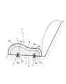
図1および図2はリアシートを示している。このリアシートでは、乗員が着座する座席部材1を構成する主要部品には、座席構成基体2と、クッション材3と、表皮材4があり、座席構成基体2の上側にはクッション材3が設けられ、該クッション材3は表皮材4に覆われている。また、座席構成基体2の下面には、固定部材5が結合されている。この固定部材5は、ショア硬度が50以上の重合体成形物(A)によって形成されたブロック5aに固定金具5bの一部が埋設された構成からなる。そして、この座席部材1は、前記固定部材5の固定金具5bを車体6のフック6aに係合させるなどの手段によって、車体6に取り付けられる。
1 and 2 show a rear seat. In the rear seat, the main components constituting the
前記座席構成基体2は、重合体発泡成形物(B)からなる。該重合体発泡成形物(B)を構成する重合体としては、合成樹脂、エラストマー、ゴムなどが挙げられる。また、該合成樹脂としては、具体的には、ポリプロピレン、ポリエチレン等のポリオレフィン系樹脂や、ポリスチレン系樹脂、ポリスチレン樹脂とポリオレフィン樹脂との複合樹脂、スチレン改質ポリエチレン樹脂、ポリエステル系樹脂、アクリル系樹脂、ポリアミド系樹脂、熱可塑性エラストマー、ウレタン系樹脂等が挙げられる。中でも、ポリプロピレン、ポリエチレン等のポリオレフィン系樹脂、ポリスチレンとポリオレフィン樹脂との複合樹脂が好適であり、ポリプロピレン樹脂が特に好適である。また、これらを単独、或いは2種以上を混合して使用することもできる。
The seat-constituting
なお,本発明でいうポリオレフィン系樹脂とは、
(1)オレフィンの単独重合体、
(2)オレフィン同士の共重合体、
(3)オレフィンと他のモノマーとの共重合体であって共重合体中のオレフィン成分比率が50重量%以上のもの、
(4)これらの2以上の混合物、或いは
(5)上記(1)乃至(4)のいずれかと、(1)乃至(4)とは異なる熱可塑性樹脂又は/及び熱可塑性エラストマーとの混合物であって混合物中のオレフィン成分比率が50重量%以上のもの
をいう。
In addition, with the polyolefin resin as used in the field of this invention,
(1) an olefin homopolymer,
(2) a copolymer of olefins,
(3) A copolymer of an olefin and another monomer having an olefin component ratio in the copolymer of 50% by weight or more,
(4) a mixture of two or more of these, or (5) a mixture of any one of (1) to (4) above and a thermoplastic resin and / or thermoplastic elastomer different from (1) to (4). That is, the olefin component ratio in the mixture is 50% by weight or more.
前記ポリオレフィン系樹脂の具体例としては、例えばプロピレン成分比率が50重量%以上である、プロピレン−ブテンランダムコポリマー、プロピレン−ブテンブロックコポリマー、エチレン−プロピレンブロックコポリマー、エチレン−プロピレンランダムコポリマー、エチレン−プロピレン−ブテンランダムターポリマー、ホモポリプロピレン、スチレン改質ポリプロピレンなどのポリプロピレン系樹脂;エチレン成分比率が50重量%以上である、低密度ポリエチレン、中密度ポリエチレン、高密度ポリエチレン、直鎖状低密度ポリエチレン、直鎖状超低密度ポリエチレン、スチレン改質ポリエチレン樹脂、エチレン−酢酸ビニルコポリマー、エチレン−メチルメタクリレートコポリマー、エチレン−メタクリル酸コポリマーの分子間を金属イオンで架橋したアイオノマー系樹脂などのポリエチレン系樹脂などの、単体または2以上の混合物、若しくはポリスチレン系樹脂、ポリエステル樹脂、ポリカーボネート樹脂のような、ポリオレフィン系樹脂以外の樹脂との2以上の混合物が挙げられる。 Specific examples of the polyolefin resin include, for example, a propylene component ratio of 50% by weight or more, a propylene-butene random copolymer, a propylene-butene block copolymer, an ethylene-propylene block copolymer, an ethylene-propylene random copolymer, an ethylene-propylene- Polypropylene resins such as butene random terpolymer, homopolypropylene, styrene modified polypropylene; low density polyethylene, medium density polyethylene, high density polyethylene, linear low density polyethylene, linear Molecules of ultra-low density polyethylene, styrene modified polyethylene resin, ethylene-vinyl acetate copolymer, ethylene-methyl methacrylate copolymer, ethylene-methacrylic acid copolymer A single or a mixture of two or more, such as a polyethylene resin such as an ionomer resin crosslinked with a metal ion, or a mixture of two or more with a resin other than a polyolefin resin such as a polystyrene resin, a polyester resin, or a polycarbonate resin Is mentioned.
これらのポリオレフィン系樹脂の中でも、本発明においては、剛性及び圧縮後の回復性に優れるという点で、プロピレン成分比率が50重量%以上、好ましくは70重量%以上、より好ましくは90重量%以上のポリプロピレン系樹脂が好ましい。また、これと同様の観点で、ポリオレフィン樹脂粒子にスチレンモノマーを含浸させて重合処理して得られた、オレフィン成分比率が25重量%以上のポリオレフィンとポリスチレンとからなる、ポリスチレンとポリオレフィンとの複合樹脂も好ましい。 Among these polyolefin-based resins, in the present invention, the propylene component ratio is 50% by weight or more, preferably 70% by weight or more, more preferably 90% by weight or more in terms of excellent rigidity and recoverability after compression. Polypropylene resins are preferred. Further, from the same viewpoint, a composite resin of polystyrene and polyolefin comprising polyolefin and polystyrene having an olefin component ratio of 25% by weight or more, obtained by impregnating polyolefin resin particles with a styrene monomer and polymerizing. Is also preferable.
また、前記座席構成基体2は、50%歪時における圧縮硬さが150kPa〜600kPaの重合体発泡成形物(B)からなる。本発明においては、従来、固定金具と一体として成形されていた座席構成基体を、固定金具5bが埋設された固定部材5と別体とした。これにより、固定金具との結合のために必要であった剛性が、座席構成基体としては不要となり、設計の自由度を拡げることが可能となる。
具体的には、前記座席構成基体2としては、従来よりも圧縮硬さの低い重合体発泡成形物(B)から構成することが可能となることから、前記クッション材3の厚みを薄くすることが可能となり、より軽量な車両用座席部材を提供することが可能となる。
また、座席構成基体2を構成する重合体発泡成形物(B)の50%歪時における圧縮硬さは、好ましくは200kPa〜500kPaであり、特に好ましくは300kPa〜400kPaである。前記圧縮硬さを上記した範囲に調節すれば、軽量ながら座席部材が座席の支持材としての剛性に特に優れるものとなる。
Moreover, the said seat structure base |
Specifically, the seat
Further, the compression hardness at the time of 50% strain of the polymer foam molded product (B) constituting the
なお、本明細書において、前記圧縮硬さの測定は次のように行うものとする。
JIS K6767(1999)に準拠して、長さ50mm、幅50mm、厚み25mmの試験片を発泡成形体から切り出し、測定機((株)島津製作所製 万能試験機オートグラフAG−5000B)を用いて測定することができる。具体的には、該試験片を測定機の平行な圧縮板の間に挟んで10mm/minの速度で初めの厚みに対し歪が60%を越えるまで圧縮して応力−歪曲線(S−S曲線)を描かせ、歪が50%の際の応力を読み取り、これを50%圧縮時における圧縮硬さとする。ただし、この圧縮硬さは、試験数を3とし、この測定値を算術平均することにより求められる。
In addition, in this specification, the measurement of the said compression hardness shall be performed as follows.
In accordance with JIS K6767 (1999), a test piece having a length of 50 mm, a width of 50 mm, and a thickness of 25 mm was cut out from the foamed molded article, and a measuring machine (Universal Tester Autograph AG-5000B, manufactured by Shimadzu Corporation) was used. Can be measured. Specifically, the test piece is sandwiched between parallel compression plates of a measuring machine and compressed at a speed of 10 mm / min until the strain exceeds 60% with respect to the initial thickness, and a stress-strain curve (SS curve). The stress when the strain is 50% is read, and this is taken as the compression hardness at 50% compression. However, this compression hardness is obtained by setting the number of tests to 3 and arithmetically averaging the measured values.
前記座席構成基体2を構成する重合体発泡成形物(B)の見掛け密度は、軽量性の観点からは、15g/L〜70g/Lであることが好ましい。
From the viewpoint of lightness, the apparent density of the polymer foam molded product (B) constituting the seat
前記座席構成基体2が、ポリオレフィン系樹脂発泡粒子成形体からなる場合には、見掛け密度が15g/L〜60g/Lであることが好ましい。該ポリオレフィン系樹脂発泡粒子成形体の見掛け密度が15g/L未満の場合には、見掛け密度が低すぎて目的とする剛性を得ることができないおそれがある。また、前記固定部材5と座席構成基体2との結合部分において、それぞれを構成する成形体の剛性の差が大きくなりすぎることから、結合部分が外れやすくなるおそれがある。一方、見掛け密度が60g/Lを超える場合には、従来よりも軽量な座席構成部材が得られなくなるおそれがある。
なお、前記ポリオレフィン系樹脂発泡粒子成形体は、上記範囲内であれば、異なる見掛け密度を有する発泡成形体を複数組み合せて、一つの発泡成形物とすることもできる。この場合には、座席構成基体の全体の平均の見掛け密度とする。
When the seat
In addition, if the said polyolefin-type resin expanded particle molded object is in the said range, it can also be combined with multiple foamed molded objects which have a different apparent density, and can also be made into one expanded molded object. In this case, the average apparent density of the entire seat constituent base is used.
座席構成基体2を構成するポリオレフィン系樹脂発泡粒子成形体の見掛け密度は、更に好ましくは25g/L〜55g/Lであり、特に好ましくは30g/L〜50g/Lである。
The apparent density of the polyolefin resin expanded particle molded body constituting the
なお、上記見掛け密度は、発泡成形体の重量(g)を、水没法から得られる発泡成形体の体積(L)で除して得るものとする。前記水没法では、発泡成形体を23℃の雰囲気温度下に24時間おいた後に、該発泡成形体を23℃の水に沈めて体積を測定するものとする。 The apparent density is obtained by dividing the weight (g) of the foamed molded product by the volume (L) of the foamed molded product obtained from the submerging method. In the submerging method, the foamed molded product is placed under an ambient temperature of 23 ° C. for 24 hours, and then the foamed molded product is submerged in water at 23 ° C. to measure the volume.
また、前記重合体発泡成形物(B)のショア硬度は、25〜70であることが好ましい。上記の関係を満足する場合には、衝突時の安全性を確保することができる上に、車両用座席部材の柔軟性を向上させることができる。前記重合体発泡成形物(B)のショア硬度が低すぎる場合には、車両の衝突時に乗員の滑り出し現象を生じるおそれがある。一方、ショア硬度が高すぎる場合には、軽量性や柔軟性が低下するおそれがある。上記観点から、さらに好ましくは30〜60、特に好ましくは35〜50である。 Moreover, it is preferable that the Shore hardness of the said polymer foaming molding (B) is 25-70. When the above relationship is satisfied, safety at the time of collision can be ensured and flexibility of the vehicle seat member can be improved. When the Shore hardness of the polymer foamed molded product (B) is too low, there is a possibility that an occupant slips out when the vehicle collides. On the other hand, if the Shore hardness is too high, the lightness and flexibility may be reduced. From the said viewpoint, More preferably, it is 30-60, Most preferably, it is 35-50.
上記座席構成基体2がポリオレフィン系樹脂発泡粒子成形体からなる場合には、ポリオレフィン系樹脂からなる発泡粒子を金型に充填してスチーム加熱成形(型内成形)することにより得ることができる。また、ブロー成形体中にポリオレフィン系樹脂発泡粒子を充填してスチーム加熱成形方法(例えば特開2000−210967号や特許第2860007号に記載の方法)により得ることもできる。更には、発泡パリソンを金型にて成形する方法(例えば特許第3646858号や特許第3707779号に記載の方法)により得ることもできる。これらの成形法の中では、複雑な形状の座席構成基体であっても容易に製造することができることから、ポリオレフィン系樹脂からなる発泡粒子を型内成形する方法が好ましい。型内成形を採用すれば、ポリオレフィン系樹脂発泡粒子を金型に送り込み、蒸気などによって樹脂発泡粒子を膨張させ、相互に融着させて成形体とすることができる。なお、発泡粒子の形状としては、円柱状、ラクビーボール状、球状、筒状などが挙げられる。
In the case where the seat
前記座席構成基体2は、上面後部に臀部収容凹部2aを備え、上面前部に隆起部2bが形成されていることが好ましい。これにより、車両の衝突時に座席から乗員の臀部が沈み込んで前方に移動しようとする際に、前方の隆起部2bが抵抗となってこれを効果的に抑制することができる。また、隆起部2bを有することで厚みが増すため、該座席構成基体2の上側に取り付けられるクッション材3の総量を低減することも可能となる。
The seat
なお、本明細書でいう座席構成基体2の後部及び前部は次の通り定義される。
座席構成基体2の前後方向(車体の前後方向)の最大長さを100%としたときに、その前後方向の最大長さと一致する仮想の直線A上において、該直線Aの最前部から40%の地点で該直線Aと直交し、かつ座席構成基体2の横方向と一致する方向に仮想の直線Bを引き、該直線Bを含みそれよりも後方に位置する部分を座席構成基体2の後部という。また、前記直線Bを含まず、それよりも前方に位置する部分を座席構成基体2の前部という。
In addition, the rear part and front part of the seat structure base |
40% from the forefront portion of the straight line A on a virtual straight line A that coincides with the maximum length in the front-rear direction when the maximum length in the front-rear direction (the front-rear direction of the vehicle body) of the
また、隆起部2bの最も高い位置である最上部は、座席構成基体2の前記直線A上において、前記最前部から30%の地点で前記直線Bと平行な仮想の直線Cを引き、該直線Cを含みそれよりも前方に位置することが好ましく、前記最前部から20%の地点で前記直線Bと平行な仮想の直線Dを引き、該直線Dを含みそれよりも前方に位置することが更に好ましく、前記最前部から15%の地点で前記直線Bと平行な仮想の直線Eを引き、該直線Eを含みそれよりも前方に位置することが特に好ましい。隆起部2bが、臀部収容凹部2aの前方の上記した位置で隆起していると、車両の衝突時に乗員の臀部が座席に沈み込んで前方に移動しようとする際に、前方の隆起部2bが抵抗となってこれを効果的に抑制することができる。また、隆起部2bを有することで、座席構成基体2の厚みが増すため、座席構成基体2の上側に取付けられるクッション材3の総量を低減することも可能となる。
The uppermost portion, which is the highest position of the raised
本発明の座席構成基体2には、上記したように臀部収容凹部2aが設けられている。この臀部収容凹部2aは、座席の後方部に位置し、乗員の臀部が配置されるものである。臀部収容凹部2aは通常の使用時において変形が少なく、丈夫であることが好ましい。そのため、該臀部収容凹部2aの最も低い部分における厚みは、0mm〜100mmであることが好ましく、5mm〜70mmであることがより好ましく、10mm〜50mmであることが更に好ましい。臀部収容凹部2aの形状としては、乗員の臀部が配置される部分は臀部に合わせて曲面形状となっていることが、乗員の座り心地の面で好ましいが、臀部収容凹部2aの形状は床に対して水平であってもよいし、隆起部2bに向かって上方に傾斜しているなどの形状であっても良い。なお、前記臀部収容凹部2aの最も低い部分における厚みが0mmとあるのは、臀部収容凹部2aの一部に穴が設けられていてもよいためである。
As described above, the seat
臀部収容凹部2aの最も低い部分である最下部と隆起部2bの最も高い位置である最上部との高低差は、臀部収容凹部2aの密度や大きさなどによって決められるが、乗員滑り出し現象を抑制するために、20mm〜200mmであることが好ましく、30mm〜175mmであることがより好ましく、50mm〜150mmであることが特に好ましい。
The difference in height between the lowest part, which is the lowest part of the
前記固定部材5は、上記したようにショア硬度が50以上の重合体成形物(A)によって形成されたブロック5aに固定金具5bの一部が埋設された構成からなる。固定金具5bは、例えば直径2mm〜8mmの金属棒をU字形状に折曲し、その両基端を抜け難いように側方に折曲した形状とされている。そのため、固定金具の基端は露出すると危険であるため、本発明においては、ショア硬度が50以上の重合体成形物(A)によって、該固定金具5bの一部、さらには固定金具の基端が覆われた構成としている。
As described above, the fixing
固定金具5bの一部が埋設された重合体成形物(A)のショア硬度は、上記したように50以上である必要があり、その上限は概ね90である。前記ショア硬度は、好ましくは52〜90であり、特に好ましくは55〜70である。
なお、本明細書においてショア硬度とは、ASTM D2240に準拠して測定されたショアA硬度を意味する。具体的には、市販されているショア硬度計、例えば、高分子計器株式会社製アスカーゴム硬度計A型、株式会社東洋精機製作所製デジタル硬度計等を用い、23℃で、相対湿度50%の条件で成形物の平坦面を測定する。
As described above, the Shore hardness of the polymer molded article (A) in which a part of the fixing metal fitting 5b is embedded needs to be 50 or more, and the upper limit is approximately 90. The Shore hardness is preferably 52 to 90, particularly preferably 55 to 70.
In addition, in this specification, a Shore hardness means the Shore A hardness measured based on ASTM D2240. Specifically, a commercially available Shore hardness tester, for example, Asker rubber hardness tester type A manufactured by Kobunshi Keiki Co., Ltd., a digital hardness tester manufactured by Toyo Seiki Seisakusho Co., Ltd., etc., is used at 23 ° C. and a relative humidity of 50%. Measure the flat surface of the molding.
固定部材5を構成する重合体成形物(A)を構成する重合体としては、ショア硬度が50以上のものであれば特には限定されないが、合成樹脂、エラストマーなどが挙げられる。また、該合成樹脂としては、具体的には、ポリプロピレン、ポリエチレン等のポリオレフィン系樹脂や、ポリスチレン系樹脂、スチレン改質ポリエチレン樹脂、ポリエステル系樹脂、アクリル系樹脂、ポリアミド系樹脂、熱可塑性エラストマー、ウレタン系樹脂等が挙げられる。中でも、ポリプロピレン、ポリエチレン等のポリオレフィン系樹脂、スチレン改質ポリエチレン系樹脂が好適であり、ポリプロピレン樹脂が特に好適である。また、これらを単独、或いは2種以上を混合して使用することもできる。
The polymer constituting the polymer molded product (A) constituting the fixing
また、固定部材5を構成する重合体成形物(A)としては、非発泡の成形体、発泡成形体を挙げることができる。この中でも、軽量性の観点からは、発泡成形体であることが好ましく、特に、ポリオレフィン系樹脂発泡成形体が好ましい。また、複雑な形状の成形物が得られることから、ポリオレフィン系樹脂発泡粒子成形体であることが好ましい。
Moreover, as a polymer molded product (A) which comprises the fixing
また、前記重合体成形物(A)がポリオレフィン系樹脂発泡成形体で構成される場合には、その見掛け密度は、50g/L以上であることが好ましく、より好ましくは、60g/L〜200g/Lであり、更に好ましくは70〜180g/Lである。 Moreover, when the said polymer molded product (A) is comprised with a polyolefin-type resin foam molding, it is preferable that the apparent density is 50 g / L or more, More preferably, it is 60 g / L-200 g / L. L, more preferably 70 to 180 g / L.
前記重合体成形物(A)は、乗員の安全性の観点からは、乗員の障害の危険が増すような鋭利な固定金具のエッジ部分の露出は避けるべきであり、構造的な強度維持の理由以外からもショア硬度50以上の材料で固定金具5bのエッジを覆い隠すのが好ましい。また、重合体成形物の形状は、柱状部と拡大部を有する形状であることが好ましく、具体的には、T字形状、或いは逆台形形状とすることが好ましい。
From the viewpoint of passenger safety, the polymer molded product (A) should avoid exposure of sharp edges of the fixing bracket that increases the risk of passenger injury, and is the reason for maintaining structural strength. It is preferable to cover the edge of the
さらに、前記固定部材5を構成する重合体成形物(A)がポリオレフィン系樹脂発泡成形体からなり、前記座席構成基体2を構成する重合体発泡成形物(B)がポリオレフィン系樹脂発泡成形体かなる場合には、見掛け密度が下式の関係を満足することが好ましい。
Da>Db
(但し、固定部材5を構成するポリオレフィン系樹脂発泡成形体の見掛け密度をDa、前記座席構成基体2を構成するポリオレフィン系樹脂発泡成形体の見掛け密度をDbとする。)
一般に、発泡成形体を成形する際には、見掛け密度の低い発泡成形体を得る方が、発泡成形体の収縮による寸法変化が起こり易くなることから、その成形が難しくなる。特に、固定金具をポリオレフィン系樹脂発泡成形体に埋設させる際には、固定金具とポリオレフィン系樹脂との収縮率が大きく異なることから、成形時の寸法精度を維持することがより難しく、高度の成形技術を要する。従って、前記座席構成基体と固定金具が埋設されたポリオレフィン系樹脂発泡成形体とを別体として成形し、前記固定部材を構成するポリオレフィン系樹脂発泡成形体の見掛け密度を高くすることができることから、固定金具の埋設を従来よりも容易に行なうことが可能となる。また、前記座席構成基体と固定金具が埋設されたポリオレフィン系樹脂発泡成形体とを別体として成形することができるため、固定部材の寸法を小さくすることが可能となることから、固定部材の寸法精度を合わせやすくなるなど、生産性が向上することも可能となる。
さらに、上式に示されるように、固定部材5を構成するポリオレフィン系樹脂発泡成形体よりも座席構成基体2を構成するポリオレフィン系樹脂発泡成形体の見掛け密度が低いことにより、より成形の困難である固定部材5を構成するポリオレフィン系樹脂発泡成形体の寸法精度が多少変化した場合であっても、寸法変化によるずれを、見掛け密度の低い座席構成基体2を構成するポリオレフィン系樹脂発泡成形体によって吸収、緩和して、座席構成基体と固定部材との結合を良好に維持することが可能となる。
Further, the polymer molding (A) constituting the fixing
Da> Db
(However, the apparent density of the polyolefin-based resin foam molding constituting the fixing
In general, when molding a foamed molded product, it is more difficult to obtain a foamed molded product having a low apparent density because dimensional changes due to shrinkage of the foamed molded product are likely to occur. In particular, when embedding a fixing bracket in a polyolefin resin foam molding, the shrinkage rate between the fixing bracket and the polyolefin resin is greatly different, so it is more difficult to maintain the dimensional accuracy at the time of molding. Requires technology. Therefore, the polyolefin resin foam molded body in which the seat constituent base and the fixing bracket are embedded is molded separately, and the apparent density of the polyolefin resin foam molded body constituting the fixing member can be increased. It becomes possible to embed the fixing bracket more easily than in the past. Further, since the polyolefin resin foam molded body in which the seat constituent base and the fixing bracket are embedded can be molded separately, it becomes possible to reduce the dimension of the fixing member. Productivity can also be improved by making it easier to match the accuracy.
Furthermore, as shown in the above formula, the apparent density of the polyolefin resin foam molded body constituting the
前記固定部材5に埋設される固定金具5bとしては、金属製のワイヤー、パイプなどが挙げられるが、車両用座席部材を車両本体に固定する強度を有するものであれば、その素材に限定されるものではない。
Examples of the fixing metal fitting 5b embedded in the fixing
前記固定部材5及び座席構成基体2を構成する重合体には、着色剤、フィラー、難燃剤などの種々の添加剤を添加することができる。
Various additives such as a colorant, a filler, and a flame retardant can be added to the polymer constituting the fixing
前記クッション材3は、通常の走行時に乗員が楽に座ることができる快適さが要求されるものであり、柔軟性を付与するために軟質発泡体で構成されることが多い。また、クッション材3は、座席構成基体2に取付けられるが、座席構成基体2とクッション材3の間に接着手段として接着層を介するなどしていても良い。しかしながら、リサイクル性を考慮すると、座席構成基体2とクッション材3が分離できるように構成されることが好ましい。
The
前記表皮材4は織物や皮製品などからなり、意匠性に富み、クッション材3を保護する機能が要求されるものである。
The skin material 4 is made of a woven fabric, a leather product, or the like, is rich in design, and requires a function of protecting the
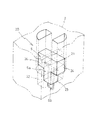
図3乃至図5には、上記した座席構成基体2と固定部材5との結合構造の一例が示されている。
この結合構造10では、図3に示すように、座席構成基体2には、凹形状または貫通穴形状からなる結合部が形成されている。該結合部は、水平断面が矩形をなす拡大空間11が形成されるとともに、座席構成基体2の底面に、該底面から拡大空間11に貫通する孔12が形成されている。なお、該結合部は、座席構成基体2の底面だけではなく、座席構成基体2の側面部分にも形成することができる。また、図3では、該結合部は、結合される固定部材5それぞれに対応して個々に形成されているが、結合部同士が連続する溝形状の凹部を形成して、一つの結合部を形成していてもよい。
一方、固定部材5のブロック5aは、水平断面が矩形の柱体部13と該柱体部13の先端に両方向に張り出す拡大部14が形成されている。そして、拡大部14の自由端部にはテーパ15aを成す尖端部15が形成され、拡大部14の先端部から下部に向けてテーパが形成されている。また、固定部材5の固定金具5bはU字状を成し、自由端部が垂直方向外方に曲折されている。そして、この固定金具5bは端部を含む一部がブロック5aに埋設されている。
FIGS. 3 to 5 show an example of a coupling structure between the seat
In this
On the other hand, the
このように形成された固定部材5は、尖端部15を座席構成基体2の孔12に挿入し、両方向に張り出す拡大部14の下部を圧縮させ、図4に示すように、その拡大部14を拡大空間11に押し込める。
In the fixing
このようにして座席構成基体2の拡大空間11に挿嵌された固定部材5の拡大部14は、図5に示したように、固定部材5の拡大部14の下面が座席構成基体2の拡大空間11の底面(斜線部分)に当接係合し、固定部材5が座席構成基体2から抜けるのを防止する。なお、前記テーパ15aの角度を調節することにより、前記固定部材5と座席構成基体2とを、脱着可能な車両用座席部材とすることも可能である。この場合には、車両用座席部材の取替えが容易となることから、利便性を向上させることが可能となる。
As shown in FIG. 5, the
なお、この状態において、固定金具5bのブロック5aから露出した部分は、座席構成基体2の下面から下方に突出した状態にある。
In this state, the portion exposed from the
座席構成基体2に形成される上記拡大空間11は、例えば、座席構成基体2の上面を形成する一方の割型に設けられた、互いに平行に間隔をもって配置した水平断面が矩形を成す一対の突起部と、座席構成基体2の下面を形成する他方の割型に設けられた、前記一対の突起部の間に挿入される水平断面が矩形を成す一つの突起部とによって形成することができる。
The
図6乃至図9には、座席構成基体2と固定部材5との結合構造の他の例が示されている。
この結合構造20では、結合部として図6に示すように、座席構成基体2に拡大空間21が形成され、座席構成基体2の底面に、該底面から拡大空間21に貫通する孔22が形成されている。この拡大空間21は、図7に示すように、水平断面が円弧状の側壁21aと該側壁21aから内方に向かって形成された平坦壁21bとによって画成される側壁が軸対称に配置された形状を成しており、前記拡大空間を前記拡大部が回動し得るように形成されている。また、孔22は水平断面が略矩形状を成している。
6 to 9 show other examples of the coupling structure of the
In the
一方、固定部材5のブロック5aは、上記の例と同様に、水平断面が矩形の柱体部23と該柱体部23の先端に両方向に張り出す拡大部24とから形成されている。また、固定部材5の固定金具5bはU字状を成し、先端部が垂直方向外方に曲折されている。そして、この固定金具5bは端部を含む一部がブロック5aに埋設されている。
On the other hand, the
この結合構造20では、固定部材5の拡大部24を図8(a)に示すように、座席構成基体2の孔22に挿入して拡大部24を座席構成基体2の拡大空間21に押し込ませ、次いで、固定部材5を図8(b)に示すように回動させる。すると、拡大部24が拡大空間21の平坦壁21bに当接するまで回動するが、それ以上の回動が規制される。そして、固定部材5の拡大部24の下面が座席構成基体2の拡大空間21の底面(斜線部分)に当接係合し、固定部材5が座席構成基体2から抜けるのを防止する。なお、この状態において、固定金具5bのブロック5aから露出した部分は、座席構成基体2の下面から下方に突出した状態にある。
In this
座席構成基体2に形成される上記拡大空間21は、例えば、座席構成基体2の上面を形成する一方の割型に設けられた、水平断面が円弧状の側壁と該側壁から内方に向かって形成された平坦壁とによって画成される形状を成す軸対称に配置された一対の突起部と、座席構成基体2の下面を形成する他方の割型に設けられた、前記一対の突起部の間に挿入される水平断面が矩形を成す一つの突起部とによって形成することができる。
The
上記座席構成基体2と固定部材5とを結合するに際しては、その間に繊維素材を介して結合することが好ましい。これは、固定部材5と座席構成基体2とが互いに接している場合には、振動等によってそれらが摺れると異音が発生するおそれがあるが、それらの間に繊維素材が介在されていれば、異音の発生を防ぐことができるためである。
When the seat
介在させる繊維素材としては、不織布、フェルト、織布などを挙げることができるが、中でも不織布が、扱い易さの観点から好ましい。また厚さは0.01mm〜1mmが好ましく、0.5mm〜2.0mmが更に好ましい。このような繊維素材を、例えば、固定部材5に被せ、座席構成基体2に形成された結合部に押し込むことにより両者間に介在させてもよく、また、固定部材5或いは座席構成基体2の必要な部位に予め繊維素材を接着しておいてもよい。
また、介在させる素材としては、繊維素材の他に、ポリオレフィン系樹脂フィルムを用いてもよい。ポリオレフィン系樹脂フィルムとしては、具体的には、厚さ0.01mm〜1mmのポリオレフィン系樹脂フィルムが挙げられる。なお、多孔のフィルムであっても支障なく使用することができる。特に好ましくは、厚さ0.05〜0.5mmの低密度ポリエチレン系フィルムが、繊維同様に価格、扱いやすさの観点から好適である。
Nonwoven fabrics, felts, woven fabrics and the like can be exemplified as the intervening fiber material. Among these, nonwoven fabrics are preferable from the viewpoint of ease of handling. The thickness is preferably 0.01 mm to 1 mm, more preferably 0.5 mm to 2.0 mm. Such a fiber material may be interposed between the two by, for example, covering the fixing
In addition to the fiber material, a polyolefin resin film may be used as the material to be interposed. Specific examples of the polyolefin resin film include polyolefin resin films having a thickness of 0.01 mm to 1 mm. Even a porous film can be used without any problem. Particularly preferably, a low-density polyethylene film having a thickness of 0.05 to 0.5 mm is suitable from the viewpoints of price and ease of handling as in the case of fibers.
〔製造例〕
成形型内に、重量25g 、直径4mmの鋼鉄製ワイヤーからなる固定金具5bを配置した。そして、エチレン− プロピレンランダム共重合樹脂発泡粒子( エチレン成分比率2.0重量%)を成形型内に充填してスチーム加熱成形することで、嵩密度110g/Lの図3に示すような形状の成形体を得た。この成形体のショア硬度は84であった。鋼鉄製ワイヤーの配置位置は、図3に示すように、固定部材5の柱状部13の先端となる位置であって、拡大部14と相対する位置に配置されていた。
[Production example]
A fixing metal fitting 5b made of steel wire having a weight of 25 g and a diameter of 4 mm was placed in the mold. Then, by filling ethylene-propylene random copolymer resin foamed particles (ethylene component ratio 2.0 wt%) in a mold and steam thermoforming, the shape as shown in FIG. 3 having a bulk density of 110 g / L is obtained. A molded body was obtained. The Shore hardness of this molded body was 84. As shown in FIG. 3, the steel wire is disposed at a position that is the tip of the
また、他の成形型内に、嵩密度0.043g /cm3のエチレン− プロピレンランダム共重合樹脂発泡粒子( エチレン成分比率2.0 重量% )を充填してスチーム加熱成形することにより、独立気泡率99% 、見掛け密度0.045g/cm3の座席構成基体を作製した。得られた座席構成基体は、幅1050mm、奥行き450mm、高さ90mmの成形物であり、結合部の形状は、図1または2に示すようなものであった。得られた座席構成基体を構成する成形物の50%歪み時における圧縮硬さは、370kPaであった。 Further, by filling ethylene-propylene random copolymer resin expanded particles (ethylene component ratio 2.0% by weight) having a bulk density of 0.043 g / cm 3 in another mold, steam heating molding is performed, thereby forming closed cells. A seat-constituting substrate having a rate of 99% and an apparent density of 0.045 g / cm 3 was produced. The obtained seat constituent base was a molded product having a width of 1050 mm, a depth of 450 mm, and a height of 90 mm, and the shape of the joint portion was as shown in FIG. The compression hardness at the time of 50% strain of the molded article constituting the obtained seat constituent base was 370 kPa.
作製した上記座席構成基体の結合部に固定部材を挿入して結合した。また、上部に厚み80mmの軟質ウレタン樹脂発泡体製のクッション材を設けて座席体とした。該座席体の総重量は4069gであった。 A fixing member was inserted into and joined to the joint portion of the seat structure base member thus produced. Further, a cushion member made of a soft urethane resin foam having a thickness of 80 mm was provided on the upper portion to obtain a seat body. The total weight of the seat body was 4069 g.
さらに、表皮材として、ファブリック素材のシートカバーを配置した。 In addition, a fabric material seat cover was placed as the skin material.
1 座席部材
2 座席構成基体
2a 臀部収容凹部
2b 隆起部
3 クッション材
4 表皮材
5 固定部材
5a ブロック
5b 固定金具
6 車体
6a フック
10 結合構造
11 拡大空間
12 孔
13 柱体部
14 拡大部
15 尖端部
15a テーパ
20 結合構造
21 拡大空間
21a 円弧状側壁
21b 平坦状側壁
22 孔
23 柱体部
24 拡大部
DESCRIPTION OF
Claims (8)
50%歪時における圧縮硬さが150kPa〜600kPaの重合体発泡成形物(B)からなる座席構成基体と、
を少なくとも備えて構成され、
前記座席構成基体に凹形状又は貫通穴形状の結合部を形成するとともに、前記結合部に前記固定部材の重合体成形物(A)を挿入して結合させることを特徴とする、
車両用座席部材。 A fixing member made of a polymer molded product (A) having a Shore hardness of 50 or more in which a part of the fixing metal is embedded;
A seat-constituting substrate made of a polymer foam molded product (B) having a compression hardness at 50% strain of 150 kPa to 600 kPa,
Comprising at least
A concave-shaped or through-hole-shaped coupling portion is formed on the seat constituent base body, and a polymer molded product (A) of the fixing member is inserted into and coupled to the coupling portion.
Vehicle seat member.
Priority Applications (1)
| Application Number | Priority Date | Filing Date | Title |
|---|---|---|---|
| JP2011122976A JP5719238B2 (en) | 2011-05-31 | 2011-05-31 | Vehicle seat members |
Applications Claiming Priority (1)
| Application Number | Priority Date | Filing Date | Title |
|---|---|---|---|
| JP2011122976A JP5719238B2 (en) | 2011-05-31 | 2011-05-31 | Vehicle seat members |
Publications (3)
| Publication Number | Publication Date |
|---|---|
| JP2012250579A JP2012250579A (en) | 2012-12-20 |
| JP2012250579A5 JP2012250579A5 (en) | 2014-07-03 |
| JP5719238B2 true JP5719238B2 (en) | 2015-05-13 |
Family
ID=47523828
Family Applications (1)
| Application Number | Title | Priority Date | Filing Date |
|---|---|---|---|
| JP2011122976A Active JP5719238B2 (en) | 2011-05-31 | 2011-05-31 | Vehicle seat members |
Country Status (1)
| Country | Link |
|---|---|
| JP (1) | JP5719238B2 (en) |
Families Citing this family (3)
| Publication number | Priority date | Publication date | Assignee | Title |
|---|---|---|---|---|
| JP6663636B2 (en) * | 2014-07-24 | 2020-03-13 | 株式会社ジェイエスピー | Vehicle seat members |
| JP6425464B2 (en) * | 2014-08-29 | 2018-11-21 | 株式会社ジェイエスピー | Fasteners for seat for vehicle and seat core for vehicle |
| JP6699371B2 (en) * | 2016-06-07 | 2020-05-27 | スズキ株式会社 | Vehicle seat back panel structure |
Family Cites Families (3)
| Publication number | Priority date | Publication date | Assignee | Title |
|---|---|---|---|---|
| JP2523301Y2 (en) * | 1991-08-27 | 1997-01-22 | ダイハツ工業株式会社 | Seat lock structure |
| AU4107597A (en) * | 1996-08-30 | 1998-03-19 | Woodbridge Foam Corporation | Seat, and process, mold and system for production thereof |
| JP3124213U (en) * | 2006-05-30 | 2006-08-10 | 株式会社ジェイエスピー | Vehicle seat members |
-
2011
- 2011-05-31 JP JP2011122976A patent/JP5719238B2/en active Active
Also Published As
| Publication number | Publication date |
|---|---|
| JP2012250579A (en) | 2012-12-20 |
Similar Documents
| Publication | Publication Date | Title |
|---|---|---|
| JP3124213U (en) | Vehicle seat members | |
| US8540318B2 (en) | Vehicle seating frame attachment assembly, and method of making the same | |
| US8696067B2 (en) | Vehicle seating frame, assembly, and method of making | |
| JP5289734B2 (en) | Eco-friendly layered seat assembly | |
| JP6864785B2 (en) | Midsole and shoes | |
| KR20110011701A (en) | Improved vehicular seating system | |
| CN101966827B (en) | Vehicle seating attachment assembly | |
| JP2018525279A (en) | Bicycle seat and method for manufacturing bicycle saddle | |
| JP5719238B2 (en) | Vehicle seat members | |
| US10124699B2 (en) | Seat assembly having shell with flexible bolsters | |
| JP5304302B2 (en) | Armrest | |
| JP5754991B2 (en) | Vehicle door trim | |
| US10315602B2 (en) | Integrated knee bolster device for vehicle | |
| JP6641564B2 (en) | pad | |
| EP3673768B1 (en) | Vehicle seat core and seat pad | |
| KR102336858B1 (en) | car seat cushion core | |
| CN110312451B (en) | Seat core material | |
| JP2016037094A (en) | Vehicular seat | |
| JP6565722B2 (en) | Vehicle seat | |
| JP4533709B2 (en) | Shock absorbing structure and manufacturing method of shock absorbing structure | |
| JP5772126B2 (en) | Vehicle ceiling material | |
| JP5320896B2 (en) | Vehicle seat pad | |
| JP2010120471A (en) | Shock absorbing structure | |
| CN110099588B (en) | In-mold foamed molded body unit and method for producing in-mold foamed molded body unit | |
| JP2005145286A (en) | Tibia pad installing structure on vehicle floor |
Legal Events
| Date | Code | Title | Description |
|---|---|---|---|
| A521 | Written amendment |
Free format text: JAPANESE INTERMEDIATE CODE: A523 Effective date: 20140521 |
|
| A621 | Written request for application examination |
Free format text: JAPANESE INTERMEDIATE CODE: A621 Effective date: 20140521 |
|
| TRDD | Decision of grant or rejection written | ||
| A977 | Report on retrieval |
Free format text: JAPANESE INTERMEDIATE CODE: A971007 Effective date: 20150128 |
|
| A01 | Written decision to grant a patent or to grant a registration (utility model) |
Free format text: JAPANESE INTERMEDIATE CODE: A01 Effective date: 20150224 |
|
| A61 | First payment of annual fees (during grant procedure) |
Free format text: JAPANESE INTERMEDIATE CODE: A61 Effective date: 20150320 |
|
| R150 | Certificate of patent or registration of utility model |
Ref document number: 5719238 Country of ref document: JP Free format text: JAPANESE INTERMEDIATE CODE: R150 |
|
| R250 | Receipt of annual fees |
Free format text: JAPANESE INTERMEDIATE CODE: R250 |
|
| R250 | Receipt of annual fees |
Free format text: JAPANESE INTERMEDIATE CODE: R250 |
|
| R250 | Receipt of annual fees |
Free format text: JAPANESE INTERMEDIATE CODE: R250 |