JP5289734B2 - Eco-friendly layered seat assembly - Google Patents
Eco-friendly layered seat assembly Download PDFInfo
- Publication number
- JP5289734B2 JP5289734B2 JP2007188921A JP2007188921A JP5289734B2 JP 5289734 B2 JP5289734 B2 JP 5289734B2 JP 2007188921 A JP2007188921 A JP 2007188921A JP 2007188921 A JP2007188921 A JP 2007188921A JP 5289734 B2 JP5289734 B2 JP 5289734B2
- Authority
- JP
- Japan
- Prior art keywords
- seat assembly
- vehicle seat
- layer
- assembly according
- cushion
- Prior art date
- Legal status (The legal status is an assumption and is not a legal conclusion. Google has not performed a legal analysis and makes no representation as to the accuracy of the status listed.)
- Expired - Fee Related
Links
- 239000000463 material Substances 0.000 claims description 52
- 239000006260 foam Substances 0.000 claims description 19
- 239000002131 composite material Substances 0.000 claims description 18
- 238000010998 test method Methods 0.000 claims description 15
- -1 polypropylene Polymers 0.000 claims description 13
- 229920002635 polyurethane Polymers 0.000 claims description 8
- 239000004814 polyurethane Substances 0.000 claims description 8
- 239000004743 Polypropylene Substances 0.000 claims description 7
- 229920001155 polypropylene Polymers 0.000 claims description 7
- 229920000098 polyolefin Polymers 0.000 claims description 5
- 239000002657 fibrous material Substances 0.000 claims description 4
- 235000010469 Glycine max Nutrition 0.000 claims 1
- 244000068988 Glycine max Species 0.000 claims 1
- 230000002708 enhancing effect Effects 0.000 claims 1
- 239000002861 polymer material Substances 0.000 claims 1
- 239000010410 layer Substances 0.000 description 61
- 229920000642 polymer Polymers 0.000 description 10
- 238000000034 method Methods 0.000 description 8
- 229920000728 polyester Polymers 0.000 description 8
- 229920002803 thermoplastic polyurethane Polymers 0.000 description 6
- 239000004677 Nylon Substances 0.000 description 5
- 230000000712 assembly Effects 0.000 description 5
- 238000000429 assembly Methods 0.000 description 5
- 239000007789 gas Substances 0.000 description 5
- 229920001778 nylon Polymers 0.000 description 5
- 239000004616 structural foam Substances 0.000 description 4
- 229920005830 Polyurethane Foam Polymers 0.000 description 3
- 230000006835 compression Effects 0.000 description 3
- 238000007906 compression Methods 0.000 description 3
- 238000004519 manufacturing process Methods 0.000 description 3
- 239000000178 monomer Substances 0.000 description 3
- 238000000465 moulding Methods 0.000 description 3
- 239000011496 polyurethane foam Substances 0.000 description 3
- 229920002397 thermoplastic olefin Polymers 0.000 description 3
- IJGRMHOSHXDMSA-UHFFFAOYSA-N Atomic nitrogen Chemical compound N#N IJGRMHOSHXDMSA-UHFFFAOYSA-N 0.000 description 2
- CURLTUGMZLYLDI-UHFFFAOYSA-N Carbon dioxide Chemical compound O=C=O CURLTUGMZLYLDI-UHFFFAOYSA-N 0.000 description 2
- 239000004698 Polyethylene Substances 0.000 description 2
- PPBRXRYQALVLMV-UHFFFAOYSA-N Styrene Chemical compound C=CC1=CC=CC=C1 PPBRXRYQALVLMV-UHFFFAOYSA-N 0.000 description 2
- 239000000853 adhesive Substances 0.000 description 2
- 230000001070 adhesive effect Effects 0.000 description 2
- 239000012790 adhesive layer Substances 0.000 description 2
- 150000001336 alkenes Chemical class 0.000 description 2
- 229920001577 copolymer Polymers 0.000 description 2
- MGNZXYYWBUKAII-UHFFFAOYSA-N cyclohexa-1,3-diene Chemical compound C1CC=CC=C1 MGNZXYYWBUKAII-UHFFFAOYSA-N 0.000 description 2
- LPIQUOYDBNQMRZ-UHFFFAOYSA-N cyclopentene Chemical compound C1CC=CC1 LPIQUOYDBNQMRZ-UHFFFAOYSA-N 0.000 description 2
- 239000000835 fiber Substances 0.000 description 2
- 239000000203 mixture Substances 0.000 description 2
- 230000035699 permeability Effects 0.000 description 2
- 229920003023 plastic Polymers 0.000 description 2
- 239000004033 plastic Substances 0.000 description 2
- 229920000573 polyethylene Polymers 0.000 description 2
- 239000011800 void material Substances 0.000 description 2
- JLBJTVDPSNHSKJ-UHFFFAOYSA-N 4-Methylstyrene Chemical compound CC1=CC=C(C=C)C=C1 JLBJTVDPSNHSKJ-UHFFFAOYSA-N 0.000 description 1
- 208000017457 Autosomal erythropoietic protoporphyria Diseases 0.000 description 1
- XDTMQSROBMDMFD-UHFFFAOYSA-N Cyclohexane Chemical compound C1CCCCC1 XDTMQSROBMDMFD-UHFFFAOYSA-N 0.000 description 1
- JOYRKODLDBILNP-UHFFFAOYSA-N Ethyl urethane Chemical compound CCOC(N)=O JOYRKODLDBILNP-UHFFFAOYSA-N 0.000 description 1
- 229910000831 Steel Inorganic materials 0.000 description 1
- 239000004433 Thermoplastic polyurethane Substances 0.000 description 1
- 239000003570 air Substances 0.000 description 1
- XYLMUPLGERFSHI-UHFFFAOYSA-N alpha-Methylstyrene Chemical compound CC(=C)C1=CC=CC=C1 XYLMUPLGERFSHI-UHFFFAOYSA-N 0.000 description 1
- 229910052782 aluminium Inorganic materials 0.000 description 1
- XAGFODPZIPBFFR-UHFFFAOYSA-N aluminium Chemical compound [Al] XAGFODPZIPBFFR-UHFFFAOYSA-N 0.000 description 1
- 230000003466 anti-cipated effect Effects 0.000 description 1
- 125000003118 aryl group Chemical group 0.000 description 1
- 239000011324 bead Substances 0.000 description 1
- 238000000071 blow moulding Methods 0.000 description 1
- 238000009835 boiling Methods 0.000 description 1
- 125000004432 carbon atom Chemical group C* 0.000 description 1
- 229910002092 carbon dioxide Inorganic materials 0.000 description 1
- 239000001569 carbon dioxide Substances 0.000 description 1
- 230000003750 conditioning effect Effects 0.000 description 1
- 125000002993 cycloalkylene group Chemical group 0.000 description 1
- 238000010586 diagram Methods 0.000 description 1
- 201000008220 erythropoietic protoporphyria Diseases 0.000 description 1
- 239000004744 fabric Substances 0.000 description 1
- 239000000945 filler Substances 0.000 description 1
- 239000006261 foam material Substances 0.000 description 1
- 239000003365 glass fiber Substances 0.000 description 1
- 239000007788 liquid Substances 0.000 description 1
- 229910001092 metal group alloy Inorganic materials 0.000 description 1
- 238000012986 modification Methods 0.000 description 1
- 230000004048 modification Effects 0.000 description 1
- 229910052757 nitrogen Inorganic materials 0.000 description 1
- JFNLZVQOOSMTJK-KNVOCYPGSA-N norbornene Chemical compound C1[C@@H]2CC[C@H]1C=C2 JFNLZVQOOSMTJK-KNVOCYPGSA-N 0.000 description 1
- JRZJOMJEPLMPRA-UHFFFAOYSA-N olefin Natural products CCCCCCCC=C JRZJOMJEPLMPRA-UHFFFAOYSA-N 0.000 description 1
- 238000004806 packaging method and process Methods 0.000 description 1
- RGSFGYAAUTVSQA-UHFFFAOYSA-N pentamethylene Natural products C1CCCC1 RGSFGYAAUTVSQA-UHFFFAOYSA-N 0.000 description 1
- YWAKXRMUMFPDSH-UHFFFAOYSA-N pentene Chemical compound CCCC=C YWAKXRMUMFPDSH-UHFFFAOYSA-N 0.000 description 1
- 229920001748 polybutylene Polymers 0.000 description 1
- 229920005862 polyol Polymers 0.000 description 1
- 150000003077 polyols Chemical class 0.000 description 1
- 229920001296 polysiloxane Polymers 0.000 description 1
- 229920006327 polystyrene foam Polymers 0.000 description 1
- 239000004800 polyvinyl chloride Substances 0.000 description 1
- 239000002990 reinforced plastic Substances 0.000 description 1
- 239000012779 reinforcing material Substances 0.000 description 1
- 238000000926 separation method Methods 0.000 description 1
- 239000007779 soft material Substances 0.000 description 1
- 239000010959 steel Substances 0.000 description 1
- 239000000126 substance Substances 0.000 description 1
- 239000000758 substrate Substances 0.000 description 1
- 238000010557 suspension polymerization reaction Methods 0.000 description 1
- 125000000383 tetramethylene group Chemical group [H]C([H])([*:1])C([H])([H])C([H])([H])C([H])([H])[*:2] 0.000 description 1
- 229920002554 vinyl polymer Polymers 0.000 description 1
- 238000003466 welding Methods 0.000 description 1
- 239000004711 α-olefin Substances 0.000 description 1
Images


Classifications
-
- B—PERFORMING OPERATIONS; TRANSPORTING
- B60—VEHICLES IN GENERAL
- B60N—SEATS SPECIALLY ADAPTED FOR VEHICLES; VEHICLE PASSENGER ACCOMMODATION NOT OTHERWISE PROVIDED FOR
- B60N2/00—Seats specially adapted for vehicles; Arrangement or mounting of seats in vehicles
- B60N2/70—Upholstery springs ; Upholstery
-
- Y—GENERAL TAGGING OF NEW TECHNOLOGICAL DEVELOPMENTS; GENERAL TAGGING OF CROSS-SECTIONAL TECHNOLOGIES SPANNING OVER SEVERAL SECTIONS OF THE IPC; TECHNICAL SUBJECTS COVERED BY FORMER USPC CROSS-REFERENCE ART COLLECTIONS [XRACs] AND DIGESTS
- Y10—TECHNICAL SUBJECTS COVERED BY FORMER USPC
- Y10S—TECHNICAL SUBJECTS COVERED BY FORMER USPC CROSS-REFERENCE ART COLLECTIONS [XRACs] AND DIGESTS
- Y10S297/00—Chairs and seats
- Y10S297/01—Foam
-
- Y—GENERAL TAGGING OF NEW TECHNOLOGICAL DEVELOPMENTS; GENERAL TAGGING OF CROSS-SECTIONAL TECHNOLOGIES SPANNING OVER SEVERAL SECTIONS OF THE IPC; TECHNICAL SUBJECTS COVERED BY FORMER USPC CROSS-REFERENCE ART COLLECTIONS [XRACs] AND DIGESTS
- Y10—TECHNICAL SUBJECTS COVERED BY FORMER USPC
- Y10S—TECHNICAL SUBJECTS COVERED BY FORMER USPC CROSS-REFERENCE ART COLLECTIONS [XRACs] AND DIGESTS
- Y10S297/00—Chairs and seats
- Y10S297/02—Molded
Description
本発明は、環境にやさしい層状車両用シート組立体及びその製造方法に関する。 The present invention relates to an environmentally friendly layered vehicle seat assembly and a method for manufacturing the same.
一般的に言えば、大半のシート組立体は、3つの基本要素:(a)シート組立体を支持し、シート組立体を車両等の車体に実装するフレーム、(b)フレームを被覆する発泡体クッション、(c)発泡体クッションを被覆し、シート組立体の乗員と接触する耐久性表面を提供するトリム材料とを含んで成る。従来の車両の座席は一般的に、環境にやさしい材料の使用に着目することなく、解体しにくいように接合させた基板構築ポリマーの混合を含む。 Generally speaking, most seat assemblies have three basic elements: (a) a frame that supports the seat assembly and mounts the seat assembly on a vehicle body such as a vehicle, and (b) a foam that covers the frame. And (c) a trim material that covers the foam cushion and provides a durable surface that contacts the occupant of the seat assembly. Conventional vehicle seats typically include a mix of substrate building polymers that are joined together so that they are difficult to disassemble without paying attention to the use of environmentally friendly materials.
したがって、環境にやさしく、構造的に堅固で快適な車両用シート組立体を提供する必要性がある。 Therefore, there is a need to provide an environmentally friendly, structurally robust and comfortable vehicle seat assembly.
本発明の少なくとも1つの態様によれば、車両用シート組立体が提供される。少なくとも1つの実施形態において、車両用シート組立体は、構造層と、該構造層に隣接するクッション層とを有するクッション複合材と、該クッション複合材を覆うように固定されたトリム材料とを含んでいる。 According to at least one aspect of the present invention, a vehicle seat assembly is provided. In at least one embodiment, a vehicle seat assembly includes a cushion composite having a structural layer, a cushion layer adjacent to the structural layer, and a trim material secured to cover the cushion composite. It is out.
少なくとも別の実施形態では、車両用シート組立体は、EPP構造層と、該構造層に隣接した大豆ベースの発泡体クッション層と、該クッション層に隣接した座り心地向上マット(快適パッド)とを含むクッション複合材と、該クッション複合材を覆うように固定されたトリム材料とを含んでいる。 In at least another embodiment, a vehicle seat assembly includes an EPP structural layer, a soy-based foam cushion layer adjacent to the structural layer, and a sitting comfort mat (comfort pad) adjacent to the cushion layer. And a trim material fixed so as to cover the cushion composite.
本発明の少なくとも別の態様によれば、車両用シート組立体の製造方法が提供される。少なくとも1つの実施形態では、該方法は、構造層と、構造層に隣接したクッション層とを備えるクッション複合材を用意すること;及びクッション複合材を覆うようにトリム材料を固定することを含む。 According to at least another aspect of the present invention, a method for manufacturing a vehicle seat assembly is provided. In at least one embodiment, the method includes providing a cushion composite comprising a structural layer and a cushion layer adjacent to the structural layer; and securing the trim material over the cushion composite.
必要に応じて、本発明の詳細な実施形態を本明細書中に開示する。しかしながら、開示される実施形態は、様々な代替形態により具現化され得る本発明の例示に過ぎないことを理解されたい。図は必ずしも正確な縮尺でなく、いくつかの特徴部は、特定の要素の詳細を示すために拡大されるか又は縮小されている場合がある。したがって、本明細書中に開示される特定の構造的及び機能的な詳細は限定的であると解釈されるべきではなく、特許請求の範囲に関する代表的な基準、及び/又は本発明を様々な様式で使用することを当業者に教示するための代表的な基準に過ぎないと解釈されるものとする。 As required, detailed embodiments of the present invention are disclosed herein. However, it is to be understood that the disclosed embodiments are merely exemplary of the invention that may be embodied by various alternative forms. The figures are not necessarily to scale, and some features may be enlarged or reduced to show details of particular elements. Accordingly, the specific structural and functional details disclosed herein are not to be construed as limiting, but are representative of the claims and / or various aspects of the invention. It should be construed as merely representative for teaching those skilled in the art to use in a form.
さらに、はっきりと別途指示される場合以外、本明細書及び特許請求の範囲における全ての数量は、本発明をより広い範囲で記述する上で「約」という単語によって修飾され得ることを理解されたい。記述される数値の限定内での実施が一般的には好ましい。また、それとは反対にはっきり記述しない限り、本発明に関連して所定の目的に好適な又は好ましい材料の群又は種類の記載は、その群又は種類の任意の2種類以上の成員の混合物も同様に好適であるか又は好まれ得ることを示す。 Further, unless expressly indicated otherwise, it is to be understood that all quantities in the specification and claims can be modified by the word “about” in describing the invention in its broader scope. . Implementation within the numerical limits described is generally preferred. Also, unless stated explicitly to the contrary, the description of a group or type of material suitable or preferred for a given purpose in connection with the present invention is the same for a mixture of any two or more members of that group or type. It may be suitable or preferred.
ここで図を参照すると、同様の数字が、各図を通して同様の構造を示すために使用され、本発明の少なくとも1つの実施形態による図式化された車両用シート組立体は一般的に、図1の10で示される。車両用シート組立体10は図1にバケットシート組立体として例示されるが、本発明の原理は、他のタイプのシート組立体、例えばベンチ、キャプテン及び他のタイプのシート組立体にも応用できることを理解されたい。また、本発明の原理は、発泡体が、バックレスト、背部サポートパッド(back support pads)、アームレスト及びヘッドレスト(head restraints)等の要素である他の構成にも応用できることを理解されたい。さらに、本発明の原理は、全タイプの車両用シート組立体、並びに非車両用シート組立体にも応用できることを理解されたい。
Referring now to the figures, like numerals are used to indicate like structures throughout the figures, and a diagrammatic vehicle seat assembly according to at least one embodiment of the present invention is generally illustrated in FIG. Of 10. Although the
図1に示されるように、車両用シート組立体10は、複数のマウンティングブラケット(図示せず)を有する一般的に14で示されるシートフレームを備えており、このシートフレームは、車両内でこれを可動式に固定するように構成されている。シートフレーム14は、車両用シート組立体10で利用するのに好適な任意の材料、例えば、アルミニウム、鋼、若しくは他の金属合金、複合材料、又は好適なポリマーで構成することができる。さらに、シートフレーム14は、使用される材料の種類に関連して、本技術分野で既知の技法を用いて製造され得る。一例として、製造技法としては、シートフレーム14を形成するのに好適な材料の型打ち、溶接、締結又は成形が挙げられる。
As shown in FIG. 1, a
また、車両用シート組立体10は、一般的に16で示されるシートバックと、一般的に18で示される下部シート組立体とを備えている。少なくとも例示した実施形態では、シートバック16及び下部シート組立体18はそれぞれ、トリム材料22によって被覆される同じクッション複合材20を有する。しかしながら、シートバック16用のクッション複合材20が、下部シート組立体18のクッション複合材20と異なることができることを理解されたい。同様に、シートバック16用のトリム材料22が、下部シート組立体18用のトリム材料22と異なることができることも理解されたい。
The
少なくとも1つの実施形態において、図1に示されるように、車両用シート組立体10は、上部サイドシールド26と、下部サイドシールド28とをそれぞれ備えている。シートシールド26及びシートシールド28は、任意の好適なプラスチック材料、例えば、ポリプロピレン、発泡ポリプロピレン、フィラー強化プラスチック、又は他のタイプのプラスチックから作製され得る。しかしながら、所望であれば、サイドシールド26及びサイドシールド28の一方又は両方を省略できることを理解されたい。同様に、以下にさらに説明するように、所望により、フレーム14を適宜省略することができることも理解されたい。図1に最適に見ることができるように、クッション複合材20は、フレーム14上又はその周囲に収められ、トリム材料22は、クッション複合材20及び/又は被覆関係にあるフレームを係合させるようになっている。
In at least one embodiment, as shown in FIG. 1, the
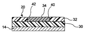
図1及び図2に最適に見ることができるように、クッション複合材20は、少なくとも例示した実施形態において、フレーム14上に配置された構造層30と、構造層30上に配置されたクッション層32とを備えている。図1及び図2に例示される実施形態に示されるクッション複合材20は適宜、クッション層32上に配置された座り心地向上パッド(快適パッド)34を備えている。以下にさらに説明するように、層30、32及び34のそれぞれは、相互に協働し、実施形態によっては、使用の最後に比較的容易に分離可能なように相互に固定される。層30、32及び34のいずれかが別の層に固定される場合、層の比較的容易な分離を可能にするように、例えば、境界面の密着力の使用、表面張力抵抗の改善、クリップ及び/又は接着剤等の好適な固定方法を使用することができる。
As best seen in FIGS. 1 and 2, the
構造層30は、任意の好適な構造発泡材料であり得る。少なくとも1つの実施形態において、好適な構造材料は、従来のポリウレタンフォームよりも大きい剛度及び/又は密度を有するであろう。少なくとも1つの実施形態において、好適な構造発泡材料は、少なくとも28.0kg/m3(1.75pcf(1立方フィート当たりのポンド))及び112kg/m3(7.0pcf)未満の密度を有する。好適な構造発泡材料は、少なくとも別の実施形態において32.0〜64.1kg/m3(2.0〜4.0pcf)、及びさらに他の実施形態では40.0〜56.1kg/m3(2.5〜3.5pcf)の密度を有する。構造発泡材料の密度は、ASTM試験法第D3574号に従って測定され得る。
The
好適な構造材料は、少なくとも1つの実施形態において150〜250N(ニュートン)、少なくとも別の実施形態では175〜230N、少なくとも別の実施形態では190〜215Nの硬度を有するであろう。硬度は、ASTM試験法第D3574号によって、25%の圧縮又はたわみにおいて測定され得る。好適な構造材料は、少なくとも1つの実施形態において、ASTM試験法第D3574号に従って測定される138〜689KPa(20〜100psi)、少なくとも別の実施形態では241〜448KPa(35〜65psi)の圧縮強度を有するであろう。 Suitable structural materials will have a hardness of 150-250 N (Newton) in at least one embodiment, 175-230 N in at least another embodiment, 190-215 N in at least another embodiment. Hardness can be measured at 25% compression or deflection according to ASTM test method D3574. Suitable structural materials, in at least one embodiment, have a compressive strength of 138-689 KPa (20-100 psi) measured according to ASTM test method D3574, and in at least another embodiment, 241-448 KPa (35-65 psi). Would have.
少なくとも1つの実施形態において、構造層30は、成形発泡ポリオレフィン(EPO)層を含む。発泡ポリオレフィン(EPO)の好適な例としては、発泡ポリエチレン(EPE);発泡ポリプロピレン(EPP);発泡ポリブチレン(EPB);及びエチレン、プロピレン、ブチレン、1,3−ブタジエン及び他のオレフィンモノマー(例えば、5〜18の炭素原子を有するα−オレフィンモノマー;及び/又はシクロヘキサン、シクロペンテン、シクロヘキサジエン、ノルボルネン等のシクロアルキレンモノマー;及びスチレン、α−メチルスチレン、パラメチルスチレン等の芳香族置換オレフィン等)のコポリマーが挙げられるが、これらに限定されない。
In at least one embodiment, the
少なくとも1つの特定の好ましい実施形態において、EPOは、発泡ポリプロピレン(EPP)、並びにエチレン、プロピレン及びブチレンとのそのコポリマーである。任意の好適なEPPを使用することができる。しかしながら、少なくとも1つの実施形態において、好適なEPPとしてはこれらに限定されるものではないが、JSP Internationalから入手可能なARPRO(登録商標)EPP、及びSCA Packaging North Americaから入手可能なEPPが挙げられる。 In at least one particular preferred embodiment, EPO is expanded polypropylene (EPP) and its copolymers with ethylene, propylene and butylene. Any suitable EPP can be used. However, in at least one embodiment, suitable EPPs include, but are not limited to, ARPRO® EPP available from JSP International, and EPP available from SCA Packaging North America. .
発泡ポリオレフィンは、比較的小さい一様なポリマービーズを生成するビーズ重合法によって調製することができ、成形プロセス時にブロー成形を行うために後で利用されるガスを含有している。ほとんどの場合に一般に使用されるガスは空気であるが、成形温度でガスを発生する低沸点の液体を含む他のガスを使用してもよい。好適なガスとしては、空気、窒素、二酸化炭素、及びペンテン等が挙げられるが、これらに限定されない。 Foamed polyolefins can be prepared by a bead polymerization process that produces relatively small, uniform polymer beads and contains a gas that is later utilized to perform blow molding during the molding process. The gas commonly used in most cases is air, although other gases including low boiling liquids that generate gas at the molding temperature may be used. Suitable gases include, but are not limited to air, nitrogen, carbon dioxide, pentene, and the like.
構造層30は、任意の好適なサイズ及び構成を有することができるが、構造層30は、少なくとも1つの実施形態において5〜100mm、他の実施形態では20〜70mm、さらに他の実施形態では30〜50mmの平均厚さを有する。
The
クッション層32は、好適な弾性ポリマー等の任意の好適なクッション材料を含んでいることができる。好適なクッション材料は、少なくとも1つの実施形態において24.0〜72.1kg/m3(1.5〜4.5pcf)、別の実施形態では32.0〜60.1kg/m3(2.0〜3.75pcf)、さらに他の実施形態では43.2〜48.1kg/m3(2.7〜3.0pcf)の密度を有するであろう。クッション材料の密度は、ASTM試験法第D3574号によって測定され得る。好適なクッション材料は、少なくとも1つの実施形態において175N(ニュートン)〜400N、他の実施形態では225〜350N、さらに他の実施形態では275〜325Nの硬度を有するであろう。クッション材料の硬度は、ASTM試験法第D3574号によって測定され得る。好適なクッション材料は、少なくとも1つの実施形態において18〜30KPa、別の実施形態では20〜28KPa、さらに他の実施形態では23〜26KPaのヒステリシスを有するであろう。クッション材料のヒステリシスは、ASTM試験法第D3574号によって測定され得る。
The
少なくとも或る実施形態において、クッション材料は、従来のポリウレタンフォーム、大豆ベースの発泡体、シリコーン、熱可塑性オレフィン、熱可塑性ウレタン、及び/又は天然油ベースの発泡ポリウレタン等を含む。少なくとも1つの実施形態では、その環境にやさしい性質から、大豆ベースのポリウレタンが好ましい。大豆ベースのポリウレタンは、必ずしも限定されないが、Bayer、Urethane Soy Systems、及びDow Chemicalから入手可能なもの等の任意の好適な大豆ベースのポリオールより生成され得る。任意の好適な大豆ベースのポリウレタンを使用してもよい。しかしながら、少なくとも1つの実施形態において、好適な大豆ベースのポリウレタンとしてはこれらに限定されるものではないが、Woodbridge Foam and Renosolから入手可能なものが挙げられる。クッション層32は、任意の好適なサイズ及び形状であり得るが、クッション層32は、少なくとも1つの実施形態において20〜100mm、少なくとも別の実施形態では30〜70mm、さらに他の実施形態では40〜60mmの平均厚さを有する。
In at least some embodiments, the cushioning material comprises conventional polyurethane foam, soy-based foam, silicone, thermoplastic olefin, thermoplastic urethane, and / or natural oil-based foamed polyurethane, and the like. In at least one embodiment, soy-based polyurethane is preferred because of its environmentally friendly nature. Soy-based polyurethanes can be made from any suitable soy-based polyol such as, but not limited to, those available from Bayer, Urethane Soy Systems, and Dow Chemical. Any suitable soy-based polyurethane may be used. However, in at least one embodiment, suitable soy-based polyurethanes include, but are not limited to, those available from Woodbridge Foam and Renosol. The
座り心地向上パッド34は、任意の好適な座り心地向上層又はパッドを含むことができ、シート組立体10が使用時にたわむような良好な手触り及び柔らかい弾性を付与する任意の好適な材料で製造することができる。クッション層32が、ASTM試験法第D3574号に従って測定される48.1kg/m3(3.0pcf)を超える密度、及び/又は25%の圧縮においてASTM試験法第D3574号に従って測定される300Nを超える硬度を有する場合に、任意の好適な座り心地向上パッド34が適宜設けられる。少なくとも1つの実施形態において、任意の好適な座り心地向上パッド34は、不織繊維材料の低硬度の発泡体又はパッド等の比較的柔らかい材料のシートを含む。座り心地向上パッド34は、任意の好適な形状及びサイズ並びに構成を有していてもよいが、座り心地向上パッド34は、少なくとも1つの実施形態において2〜30mm、他の実施形態では5〜20mm、さらに他の実施形態では8〜15mmの平均厚さを有する。
Sitting
少なくとも1つの実施形態において、座り心地向上パッド34は、ポリエステル又はナイロンの不織繊維パッドを含む。少なくとも1つの実施形態において、座り心地向上パッド34は、トリム材料22と適合性を有する(すなわち、類似のポリマータイプ)の不織圧縮繊維材料を含む。少なくとも1つの実施形態において、不織繊維材料の座り心地向上パッド34は、5〜15mmの厚さ及び57〜170g(2〜6oz)を有する。
In at least one embodiment, the
少なくとも別の実施形態において、座り心地向上パッド34は、8〜20mmの平均厚さの発泡体を有するシートを含む。少なくとも1つの実施形態において、発泡体製座り心地向上パッド34は、ASTM試験法第D3574号に従って測定された28.8〜40.0kg/m3(1.8〜2.5pcf)の密度を有する。少なくとも1つの実施形態において、発泡体製座り心地向上パッド34は、25%の圧縮又はたわみにおけるASTM試験法第D3574号に従って測定される5〜12Nの硬度を有する。少なくとも或る実施形態において、発泡体製座り心地向上パッド34は、56.6l/分(2.0立方フィート/分)を超える通気性(透過度)、及び/又はわずか20%の圧縮ひずみ(75%)を有し得る。
In at least another embodiment, the
構造層30、クッション層32、及び座り心地向上パッド34が、任意の好適な構成、形状及びサイズを有し得ることを理解されたい。例えば、図2に示されるように、層30、32及び34のそれぞれは類似のサイズ及び構造を有し、構造層30はフレーム14上に配置され、クッション層32は構造層上に配置され、座り心地向上パッド34はクッション層上に配置される。
It should be understood that the
図3に示されるように、クッション層32は、座り心地向上パッド34を収める空隙42を規定する内表面40を有する。図3には別の実施形態が例示される。すなわち、構造層30は、フレーム14上に配置された全体的に均質な材料の層からなることができ、クッション層32は、座り心地向上パッド34を収める空隙42を有する中空層から成る。
As shown in FIG. 3, the
図4を参照すると、構造層30がクッション層32を収める空隙を有するように構成される代替的な構成が示される。図4に示されるように、座り心地向上パッド34は構造層30及びクッション層32の双方の上に延在していてもよく、別の実施形態(図示せず)では、座り心地向上パッド34はクッション層32又は構造層30のいずれかの上にのみ存在していてもよい。予想され得るように、本明細書中に提示も記載もされなくとも、層30〜層34の種々の構成も本発明によって包含され得る。
Referring to FIG. 4, an alternative configuration is shown in which the
上述したように、車両用シート組立体10はまた、被覆関係でクッション複合材20と係合するようになっているトリム材料22を備えている。トリム材料22としては、本技術分野で既知の任意の材料を挙げることができる。一例として、いくつかの既知の材料としては、シートトリム用途に使用するのに十分な品質及び厚さの布地、皮又はポリマーを挙げることができる。ポリマートリム材料としては、可撓性の内発泡ポリマー表皮材料、例えば、ポリビニル、ポリ塩化ビニル(PVC)、ポリエステル、ナイロン、熱可塑性オレフィン(TPO)又は熱可塑性ウレタン(TPU)を挙げることができる。トリム材料22として使用されるさらなる材料としては、様々なポリマー発泡材料から製造され得るフォームバッキング(図示しないが、一般的には本技術分野で既知である)を挙げることができる。一例として、フォームバッキングは、ポリエチレンフォーム、ポリプロピレンフォーム、ポリウレタンフォーム又はポリスチレンフォームであってもよい。適宜、網状材料又は強化材料(図示しないが、一般的に本技術分野で既知である)、例えば、ガラス繊維、ナイロン、ポリエステル又は天然繊維が、剛性を高めることなく強度を高めるように、トリム材料22のフォームバッキング又は裏面に適用され得る。少なくとも1つの特に好ましい実施形態において、トリム材料22は、車両用シート組立体10の1つ又は複数の要素(すなわち、クッション20及び/又はフレーム14)にトリム材料22を固定するためのポリエステル又はナイロンのトリムファスナー(図示せず)を有する、ポリエステル又はナイロンのトリム材料を含む。
As described above, the
少なくとも或る実施形態において、クッション複合材20の層30〜層34は、組立を容易に促進することができるように、また再利用のためのライン解体を容易に済ませるために容易に解体できるように構成される。少なくとも1つの実施形態において、層30〜層34は、任意の好適な機械的締結によって相互に固定されるものではない。この実施形態において、層30〜層34はいずれも、互いの上に且つ/又は調節層のくぼみ内に置かれ、上部を被覆しているトリム材料22によって接ぎ合わされている。図6に概略的に例示されるような他の実施形態において、1つ又は複数の層30〜層34は、図6の50で概略的に例示される機械的締結要素を有し得る。少なくとも1つの実施形態において、機械的締結要素50は、雌型凹部54内に収容可能な雄型凸部52を隣接する層に備え得る。
In at least some embodiments, the layers 30-34 of the
少なくとも他の実施形態において、機械的締結要素50は接着層を含み得る。車両用シート組立体10の環境にやさしい配慮を伴って、再利用し易さから、使用される任意の接着層は、1つ又は複数の隣接する層に適合性を有するものとする。例えば、ポリエステル系接着剤は、ポリエステルのトリム22を不織ポリエステルの座り心地向上層34に接着させることで、層中の共有ポリマー含量を維持するのに使用することができる。同様に、取付けクリップをポリウレタン層に使用する場合、取付けクリップは熱可塑性ポリウレタン(TPU)から成形することができ、層中のポリマー含有量の共有性は再び維持される。分離される場合、TPUクリップは、支持ポリウレタン層中に残存することができる。
In at least other embodiments, the
上述したように、本発明の車両用シート組立体10は容易に再利用可能である。これに関連して、層30〜層34は、相互に且つトリム材料22から、比較的簡単な直接的な方法で容易に分離することができる。例えば、層30〜層34は、いかなる問題も生じることなく別個に再利用することもでき、また別個の流れで再利用することもできる。
As described above, the
図5を参照すると、シート組立体10の代替的な実施形態が例示される。この実施形態において、図1〜図4に例示されるシートフレーム14は省かれている。このような構成は一般的に、第2列シートや第3列シートとしてより実用的である。
Referring to FIG. 5, an alternative embodiment of the
以上、本発明の実施形態を例示し、説明したが、これらの実施形態は、本発明の全ての可能な形態を例示、説明することを意図したものではない。また、本明細書中に使用される単用語は、本発明を説明するための用語であって限定するものではなく、本発明の精神及び範囲を逸脱しない限り、様々な変更が成され得ることが理解されよう。 While embodiments of the present invention have been illustrated and described above, these embodiments are not intended to exemplify and describe all possible forms of the invention. Further, the single terms used in the present specification are terms for describing the present invention and are not intended to limit the present invention, and various modifications can be made without departing from the spirit and scope of the present invention. Will be understood.
Claims (14)
成形発泡ポリオレフィン構造層と、発泡クッション層であって、実質的に該構造層に隣接している発泡クッション層とを有するクッション複合材;及び
該クッション複合材を覆って固定されたトリム材料とを含んでおり、
該クッション複合材が、該構造層と該トリム材料との間に配置された座り心地向上パッドをさらに有しており、該座り心地向上パッドが該クッション層の不連続部分に該構造層に接触して配置されているか、または該クッション層が該構造層の不連続部分に該座り心地向上パッドに接触して配置されており、該座り心地向上パッドがASTM試験法第D3574号に従って測定された1.8〜2.5pcfの密度を有し、かつ該クッション層がASTM試験法第D3574号に従って測定された3.0pcfを超える密度を有し、さらに該構造層、該クッション層、該座り心地向上パッド及び該トリム材料が、互いに分離できるように相互に固定されていないことを特徴とする車両用シート組立体。 A vehicle seat assembly comprising:
A cushion composite having a molded foamed polyolefin structural layer, and a foam cushion layer, the foam cushion layer being substantially adjacent to the structural layer; and a trim material secured over the cushion composite. Including
The cushion composite further includes a sitting comfort pad disposed between the structural layer and the trim material, and the sitting comfort pad contacts the structural layer at a discontinuous portion of the cushion layer. Or the cushion layer is disposed in contact with the comfort-improving pad at a discontinuous portion of the structural layer, and the comfort-improving pad was measured according to ASTM test method D3574 Having a density of 1.8 to 2.5 pcf and the cushion layer having a density exceeding 3.0 pcf measured according to ASTM test method D3574, and further comprising the structural layer, the cushion layer, and the sitting comfort A vehicle seat assembly, wherein the enhancement pad and the trim material are not secured together so as to be separable from each other.
Applications Claiming Priority (2)
| Application Number | Priority Date | Filing Date | Title |
|---|---|---|---|
| US11/458832 | 2006-07-20 | ||
| US11/458,832 US7585030B2 (en) | 2006-07-20 | 2006-07-20 | Environmentally friendly layered seating assembly |
Related Child Applications (1)
| Application Number | Title | Priority Date | Filing Date |
|---|---|---|---|
| JP2011217738A Division JP2012046181A (en) | 2006-07-20 | 2011-09-30 | Environmentally friendly layered seating assembly |
Publications (2)
| Publication Number | Publication Date |
|---|---|
| JP2008023340A JP2008023340A (en) | 2008-02-07 |
| JP5289734B2 true JP5289734B2 (en) | 2013-09-11 |
Family
ID=38476574
Family Applications (2)
| Application Number | Title | Priority Date | Filing Date |
|---|---|---|---|
| JP2007188921A Expired - Fee Related JP5289734B2 (en) | 2006-07-20 | 2007-07-20 | Eco-friendly layered seat assembly |
| JP2011217738A Pending JP2012046181A (en) | 2006-07-20 | 2011-09-30 | Environmentally friendly layered seating assembly |
Family Applications After (1)
| Application Number | Title | Priority Date | Filing Date |
|---|---|---|---|
| JP2011217738A Pending JP2012046181A (en) | 2006-07-20 | 2011-09-30 | Environmentally friendly layered seating assembly |
Country Status (4)
| Country | Link |
|---|---|
| US (3) | US7585030B2 (en) |
| JP (2) | JP5289734B2 (en) |
| DE (1) | DE102007027496B4 (en) |
| GB (1) | GB2440274B (en) |
Families Citing this family (50)
| Publication number | Priority date | Publication date | Assignee | Title |
|---|---|---|---|---|
| CN101415639B (en) * | 2006-03-31 | 2011-11-09 | 东京座椅技术股份有限公司 | Cushion body, sitting seat and process for manufacturing them |
| US7585030B2 (en) * | 2006-07-20 | 2009-09-08 | Galbreath Ashford A | Environmentally friendly layered seating assembly |
| US20080185900A1 (en) * | 2006-09-28 | 2008-08-07 | Lee Ellen Cheng-Ch | Use of renewable and biodegradable materials for automotive interiors |
| US20080164730A1 (en) * | 2007-01-05 | 2008-07-10 | Ford Global Technologies, Llc | Insert for vehicle seat head restraint |
| US7946649B2 (en) * | 2007-10-01 | 2011-05-24 | Lear Corporation | Vehicle seat assembly having layered seating system with attachment member |
| JP5098612B2 (en) * | 2007-12-07 | 2012-12-12 | トヨタ紡織株式会社 | Piece for skin material of vehicle seat and manufacturing method thereof |
| US9555728B2 (en) * | 2008-06-03 | 2017-01-31 | Lear Corporation | Layered seating system with attachments |
| FR2934195B1 (en) * | 2008-07-24 | 2011-04-01 | Faurecia Sieges Automobile | TRIM FORMING FOR MOTOR VEHICLE SEATS |
| US8020937B2 (en) * | 2008-07-31 | 2011-09-20 | Lear Corporation | Layered technology for energy management of vehicle seating |
| DE102008035611A1 (en) * | 2008-07-31 | 2010-02-04 | Johnson Controls Gmbh | Upholstery element, in particular a seat cushion element of different hardness zones for use in a motor vehicle, method for producing a cushion element and vehicle seat |
| US8282164B2 (en) * | 2008-08-01 | 2012-10-09 | Lear Corporation | Seating durability layer electrical, mechanical and connecting system integration |
| US7850247B2 (en) * | 2008-09-19 | 2010-12-14 | Lear Corporation | Vehicle seat assembly with polymeric cushion pan |
| US8991930B2 (en) * | 2008-09-22 | 2015-03-31 | Johnson Controls Technology Company | Closed cell foam vehicle interior component and method of making same |
| GB0819199D0 (en) * | 2008-10-20 | 2008-11-26 | Will Beck And Jsp Ltd | Furniture with detachable arpro |
| US8141957B2 (en) * | 2008-12-15 | 2012-03-27 | La-Z-Boy Incorporated | Cushion with plural zones of foam |
| US20100151227A1 (en) * | 2008-12-17 | 2010-06-17 | International Automative Components Group North America, Inc. | Interior panel component for use with a vehicle and method for making |
| US7959233B2 (en) * | 2008-12-19 | 2011-06-14 | Toyota Motor Engineering & Manufacturing North America, Inc. | Seat back assembly with integral reinforcement structure |
| US8414053B2 (en) | 2008-12-19 | 2013-04-09 | Toyota Motor Engineering & Manufacturing North America, Inc. | Seat back assembly with integral reinforcement structure |
| US7954899B2 (en) | 2008-12-22 | 2011-06-07 | Toyota Motor Engineering & Manufacturing North America, Inc. | Seat back assembly with an adjustable headrest |
| US8157322B2 (en) * | 2008-12-22 | 2012-04-17 | Toyota Motor Engineering & Manufacturing North America, Inc. | Seat back assembly with low density frame |
| US8696067B2 (en) * | 2009-07-27 | 2014-04-15 | Lear Corporation | Vehicle seating frame, assembly, and method of making |
| US8662560B2 (en) * | 2009-07-27 | 2014-03-04 | Lear Corporation | Vehicle seating attachment assembly |
| US8262157B2 (en) * | 2009-11-25 | 2012-09-11 | Leslie Aisner Novak | Hinge collapsible portable slat seat |
| JP5463903B2 (en) * | 2009-12-24 | 2014-04-09 | トヨタ紡織株式会社 | Cushion material for vehicle seat |
| DE112010005314T5 (en) * | 2010-02-26 | 2012-12-20 | Lear Corporation | Seat pad made of fiber composite |
| US8215714B2 (en) | 2010-05-17 | 2012-07-10 | Lear Corporation | Vehicle seat assembly with interlocking layered seating system |
| MY165807A (en) * | 2010-10-01 | 2018-04-27 | Nissan Motor | Vehicle seat and stiffness setting method for vehicle seat technical field |
| GB2474749B8 (en) * | 2010-10-01 | 2011-10-26 | Porter And Davies Ltd | A vibration seat |
| US8540318B2 (en) | 2011-01-20 | 2013-09-24 | Lear Corporation | Vehicle seating frame attachment assembly, and method of making the same |
| DE102011121991B4 (en) * | 2011-12-22 | 2014-02-27 | Grammer Ag | Vehicle seat and method for manufacturing a vehicle seat cushion part |
| US8974003B2 (en) * | 2012-03-30 | 2015-03-10 | Toyota Motor Engineering & Manufacturing North America, Inc. | Rear seat cushion sound reduction mat |
| JP2014057633A (en) * | 2012-09-14 | 2014-04-03 | Toyota Boshoku Corp | Vehicle seat |
| FR3009224B1 (en) | 2013-08-02 | 2016-01-01 | Faurecia Sieges Automobile | METHOD OF FORMING TRIM FOR AUTOMOTIVE SEAT |
| FR3009222B1 (en) | 2013-08-02 | 2016-01-01 | Faurecia Sieges Automobile | FORMING A TRIM FOR A MOTOR VEHICLE SEAT |
| US9227541B2 (en) * | 2013-10-16 | 2016-01-05 | Ford Global Technologies, Llc | Composite modular rear seat structure frame |
| WO2016097719A1 (en) * | 2014-12-17 | 2016-06-23 | Bentley Motors Limited | Seat |
| CA2977551C (en) * | 2015-02-27 | 2020-09-01 | Proprietect L.P. | Vehicular seat element |
| FR3035038B1 (en) | 2015-04-16 | 2017-05-12 | Faurecia Sieges D'automobile | ALIGNMENT OF COIFFE PARTS FOR SEATS OF MOTOR VEHICLES |
| US10259353B2 (en) | 2015-04-23 | 2019-04-16 | Syntec Seating Solutions, Llc | School bus seat |
| US9914382B2 (en) | 2016-02-16 | 2018-03-13 | Lear Corporation | Seat assembly having structural foam with intergrated frame support and method of making the same |
| JP6572801B2 (en) * | 2016-03-03 | 2019-09-11 | テイ・エス テック株式会社 | Vehicle seat |
| GB2548907B (en) * | 2016-04-01 | 2021-06-16 | Mirus Aircraft Seating Ltd | Cushion assembly |
| JP2017221281A (en) * | 2016-06-13 | 2017-12-21 | 株式会社イノアックコーポレーション | Seat member, and production thereof |
| WO2018081199A1 (en) | 2016-10-28 | 2018-05-03 | Bose Corporation | Backrest speakers with acoustic channels |
| US20190100122A1 (en) * | 2017-10-04 | 2019-04-04 | Ford Global Technologies, Llc | Waterproof skinned bench seat |
| EP3802210B1 (en) * | 2018-06-08 | 2022-08-03 | Bose Corporation | Headrests |
| JP7283248B2 (en) | 2019-06-18 | 2023-05-30 | トヨタ紡織株式会社 | vehicle seat |
| US11712825B2 (en) * | 2019-09-10 | 2023-08-01 | Ford Global Technologies, Llc | Trim article having an integrated structural composition with variated densities and methods for making the same |
| US11590869B2 (en) | 2021-05-28 | 2023-02-28 | Bose Corporation | Seatback speakers |
| US11647327B2 (en) | 2020-06-01 | 2023-05-09 | Bose Corporation | Backrest speakers |
Family Cites Families (52)
| Publication number | Priority date | Publication date | Assignee | Title |
|---|---|---|---|---|
| US2191956A (en) * | 1939-02-27 | 1940-02-27 | Darius D Coldren | Slip-on cover for seats of passenger vehicles |
| US3833259A (en) * | 1972-05-30 | 1974-09-03 | Deere & Co | Vehicle seat comprising three foam layers |
| US3987507A (en) * | 1975-08-25 | 1976-10-26 | Everest & Jennings, Inc. | Pressure distribution pad assembly for wheelchairs |
| US4673216A (en) * | 1984-08-06 | 1987-06-16 | Alfer Jaroslaw G | Basic lotus posture comfort seat |
| US4999068A (en) * | 1986-02-24 | 1991-03-12 | Chiarella Michele A | Method for making an anatomical multilayer bicycle-type seat |
| US4753480A (en) * | 1986-08-14 | 1988-06-28 | Morell Theodore R | Pad assembly for wheelchairs |
| US4755411A (en) | 1987-04-22 | 1988-07-05 | Milsco Limited | Cushion having flexible outer membrane and multi-density resilient foam member therein |
| US4744601A (en) * | 1987-04-29 | 1988-05-17 | Kabushiki Kaisha Cubic Engineering | Headrest apparatus |
| US4852228A (en) * | 1987-10-26 | 1989-08-01 | Hoover Universal, Inc. | Method of Manufacturing a vehicle seat with mold-in-face suspension system |
| US4861104A (en) * | 1988-01-29 | 1989-08-29 | General Motors Corporation | Seat cushion construction and method of utilization thereof |
| US5000515A (en) | 1989-02-14 | 1991-03-19 | Hoover Universal, Inc. | Variable density foam vehicle seat |
| JPH0655466B2 (en) * | 1989-12-20 | 1994-07-27 | 住友化学工業株式会社 | Laminated body and manufacturing method thereof |
| JPH0483830A (en) | 1990-07-27 | 1992-03-17 | Honda Motor Co Ltd | Method for improving magnetic characteristic of rare-earth alloy for permanent magnet |
| SE466903B (en) | 1990-08-23 | 1992-04-27 | Volvo Ab | Widenable, Hopefully Vehicle Seat for Children |
| JPH0483830U (en) * | 1990-11-29 | 1992-07-21 | ||
| US5352023A (en) * | 1992-09-16 | 1994-10-04 | Jay Medical, Ltd. | Seating and back systems for a wheelchair |
| JPH06126755A (en) * | 1992-10-15 | 1994-05-10 | Bridgestone Corp | Method for molding polyurethane sheet pad |
| ATA20593A (en) | 1993-02-05 | 1998-08-15 | Greiner & Soehne C A | VEHICLE SEAT, IN PARTICULAR FOR AIRCRAFT |
| FR2707972B1 (en) | 1993-06-29 | 1995-09-22 | Bfa | Improvements to the padding of motor vehicle seats. |
| AT400700B (en) | 1993-11-03 | 1996-02-26 | Greiner & Soehne C A | VEHICLE SEAT WITH A SEAT PAD, IN PARTICULAR AIRPLANE SEAT |
| US5472307A (en) * | 1994-09-09 | 1995-12-05 | Anthony J. Kadlec | Wheelchair tilt lift |
| US5687436A (en) * | 1996-08-09 | 1997-11-18 | Jay Medical Ltd. | Wheelchair seating cushion having adjustable top contour shape |
| US5882073A (en) * | 1996-08-30 | 1999-03-16 | Woodbridge Foam Corporation | Foam passenger seat having trim cover attachment means |
| US5786394A (en) | 1996-12-04 | 1998-07-28 | Lear Corporation | Durable, energy-absorptive EPP/PUR structural composites |
| JPH10250440A (en) | 1997-03-14 | 1998-09-22 | Araco Corp | Assembly structure for rear seat cushion |
| US6089657A (en) | 1997-09-11 | 2000-07-18 | Toyo Tire & Rubber Co., Ltd. | Seat cushion pad for automobiles |
| DE19751091A1 (en) | 1997-11-18 | 1999-05-20 | Bayerische Motoren Werke Ag | Vehicle seat with modular upholstery |
| JP2000004993A (en) * | 1998-06-18 | 2000-01-11 | T S Tec Kk | Automotive seat |
| US6007149A (en) * | 1998-09-04 | 1999-12-28 | Yates; Paul M. | Bicycle saddle with adjustable cushioning |
| DE19845730B4 (en) | 1998-10-05 | 2005-02-10 | Audi Ag | cushion support |
| JP2001054690A (en) | 1999-08-17 | 2001-02-27 | Teijin Ltd | Cushioning material formed of fiber aggregate |
| JP4461532B2 (en) * | 1999-12-08 | 2010-05-12 | 株式会社ブリヂストン | Vehicle seat and manufacturing method thereof |
| US6543843B1 (en) * | 2000-03-16 | 2003-04-08 | Johnson Controls Technology Company | Fastener strip |
| JP2001333839A (en) * | 2000-05-26 | 2001-12-04 | Kawashima Textile Manuf Ltd | Cushion |
| US6271279B1 (en) * | 2000-07-10 | 2001-08-07 | Bayer Corporation | High resilient flexible urethane foam and flexible molded foams based on allophanate modified isocyanates |
| FR2815901B1 (en) | 2000-10-31 | 2003-08-08 | Faurecia Sieges Automobile | UPHOLSTERED ELEMENT FOR VEHICLE AND MANUFACTURING METHOD THEREOF |
| SE0100324D0 (en) * | 2001-02-02 | 2001-02-02 | Gunnar Baltzer | Headrest for alleviating whiplash injury and the use of specific polyurethane foams therein |
| DE60205492T2 (en) * | 2001-08-15 | 2006-06-08 | Dow Global Technologies, Inc., Midland | IMPROVED SEATING SYSTEM |
| JP2003199644A (en) * | 2002-01-09 | 2003-07-15 | Takashimaya Nippatsu Kogyo Co Ltd | Seat for vehicle |
| JP2003291704A (en) * | 2002-04-08 | 2003-10-15 | Nissan Motor Co Ltd | Shock absorber |
| US20040084937A1 (en) | 2002-11-04 | 2004-05-06 | Berta Michael J. | Vehicle seat component and method for making same |
| NL1022632C2 (en) | 2003-02-10 | 2004-08-12 | Recticel Nederland Bv | Seat as well as seating device provided with such a seat. |
| US6739655B1 (en) * | 2003-02-28 | 2004-05-25 | Polaris Industries Inc. | Recreational vehicle seat with storage pocket |
| FR2864483B1 (en) | 2003-12-24 | 2007-03-30 | Faurecia Sieges Automobile | VEHICLE SEAT SEAT MATTRESS AND SITTING PROVIDED WITH SUCH A MATTRESS |
| JP2005261565A (en) * | 2004-03-17 | 2005-09-29 | Honda Motor Co Ltd | Seat for vehicle |
| JP2005320437A (en) * | 2004-05-10 | 2005-11-17 | Honda Motor Co Ltd | Urethane foam for automobile seat |
| JP2005320431A (en) | 2004-05-10 | 2005-11-17 | Honda Motor Co Ltd | Cushion for automobile seat made from flexible polyurethane foam derived from soybean oil |
| US7312343B2 (en) * | 2004-06-02 | 2007-12-25 | Hoffmann-La Roche Inc. | Synthesis of α-amino-β-alkoxy-carboxylic acid esters |
| US20050282921A1 (en) * | 2004-06-18 | 2005-12-22 | Ford Global Technologies, Llc | Automotive grade, flexible polyurethane foam and method for making the same |
| US7032967B2 (en) | 2004-07-30 | 2006-04-25 | Pyzik Matthew R | Structural foam and urethane composite for use in a motorcycle seat and method of manufacturing the same |
| US7487575B2 (en) * | 2005-07-13 | 2009-02-10 | Lyle J Smith | System for attaching trim covers to a flexible substrate |
| US7585030B2 (en) * | 2006-07-20 | 2009-09-08 | Galbreath Ashford A | Environmentally friendly layered seating assembly |
-
2006
- 2006-07-20 US US11/458,832 patent/US7585030B2/en active Active
-
2007
- 2007-06-19 DE DE102007027496A patent/DE102007027496B4/en active Active
- 2007-07-19 GB GB0714039A patent/GB2440274B/en active Active
- 2007-07-20 JP JP2007188921A patent/JP5289734B2/en not_active Expired - Fee Related
-
2009
- 2009-08-18 US US12/543,080 patent/US7905552B2/en active Active
-
2011
- 2011-02-17 US US13/029,512 patent/US8657383B2/en active Active
- 2011-09-30 JP JP2011217738A patent/JP2012046181A/en active Pending
Also Published As
| Publication number | Publication date |
|---|---|
| US8657383B2 (en) | 2014-02-25 |
| JP2012046181A (en) | 2012-03-08 |
| GB2440274A (en) | 2008-01-23 |
| US20080018162A1 (en) | 2008-01-24 |
| GB2440274B (en) | 2009-02-18 |
| JP2008023340A (en) | 2008-02-07 |
| DE102007027496A1 (en) | 2008-01-24 |
| US20110140500A1 (en) | 2011-06-16 |
| US7905552B2 (en) | 2011-03-15 |
| GB0714039D0 (en) | 2007-08-29 |
| US7585030B2 (en) | 2009-09-08 |
| US20090302664A1 (en) | 2009-12-10 |
| DE102007027496B4 (en) | 2010-11-04 |
Similar Documents
| Publication | Publication Date | Title |
|---|---|---|
| JP5289734B2 (en) | Eco-friendly layered seat assembly | |
| US8696067B2 (en) | Vehicle seating frame, assembly, and method of making | |
| US10676000B2 (en) | Layered seating system with attachments | |
| US7419209B1 (en) | Seat assembly providing airflow path to cool batteries | |
| US7967389B2 (en) | Vehicle seat assembly having layered seating system | |
| US9914382B2 (en) | Seat assembly having structural foam with intergrated frame support and method of making the same | |
| US8540318B2 (en) | Vehicle seating frame attachment assembly, and method of making the same | |
| US8215714B2 (en) | Vehicle seat assembly with interlocking layered seating system | |
| US7946649B2 (en) | Vehicle seat assembly having layered seating system with attachment member | |
| US8662560B2 (en) | Vehicle seating attachment assembly | |
| WO2014203890A1 (en) | Seat cushion | |
| JP5864613B2 (en) | Vehicle seat back | |
| US20180170217A1 (en) | Seat assembly having shell with flexible bolsters | |
| JP2016037094A (en) | Vehicular seat | |
| JP6046816B2 (en) | Seat cushion | |
| JP6075552B2 (en) | Vehicle seat cushion | |
| JP2016093461A (en) | Seat cushion body for vehicle | |
| JP2016036428A (en) | Seat cushion | |
| JP2016093460A (en) | Seat cushion body for vehicle |
Legal Events
| Date | Code | Title | Description |
|---|---|---|---|
| A621 | Written request for application examination |
Free format text: JAPANESE INTERMEDIATE CODE: A621 Effective date: 20071214 |
|
| A977 | Report on retrieval |
Free format text: JAPANESE INTERMEDIATE CODE: A971007 Effective date: 20101105 |
|
| A131 | Notification of reasons for refusal |
Free format text: JAPANESE INTERMEDIATE CODE: A131 Effective date: 20101110 |
|
| A601 | Written request for extension of time |
Free format text: JAPANESE INTERMEDIATE CODE: A601 Effective date: 20110210 |
|
| A602 | Written permission of extension of time |
Free format text: JAPANESE INTERMEDIATE CODE: A602 Effective date: 20110216 |
|
| A521 | Request for written amendment filed |
Free format text: JAPANESE INTERMEDIATE CODE: A523 Effective date: 20110510 |
|
| A02 | Decision of refusal |
Free format text: JAPANESE INTERMEDIATE CODE: A02 Effective date: 20110530 |
|
| A521 | Request for written amendment filed |
Free format text: JAPANESE INTERMEDIATE CODE: A523 Effective date: 20110930 |
|
| A521 | Request for written amendment filed |
Free format text: JAPANESE INTERMEDIATE CODE: A821 Effective date: 20111003 |
|
| A911 | Transfer to examiner for re-examination before appeal (zenchi) |
Free format text: JAPANESE INTERMEDIATE CODE: A911 Effective date: 20111201 |
|
| A912 | Re-examination (zenchi) completed and case transferred to appeal board |
Free format text: JAPANESE INTERMEDIATE CODE: A912 Effective date: 20111222 |
|
| A601 | Written request for extension of time |
Free format text: JAPANESE INTERMEDIATE CODE: A601 Effective date: 20120612 |
|
| A602 | Written permission of extension of time |
Free format text: JAPANESE INTERMEDIATE CODE: A602 Effective date: 20120618 |
|
| A601 | Written request for extension of time |
Free format text: JAPANESE INTERMEDIATE CODE: A601 Effective date: 20130118 |
|
| A602 | Written permission of extension of time |
Free format text: JAPANESE INTERMEDIATE CODE: A602 Effective date: 20130123 |
|
| A601 | Written request for extension of time |
Free format text: JAPANESE INTERMEDIATE CODE: A601 Effective date: 20130218 |
|
| A602 | Written permission of extension of time |
Free format text: JAPANESE INTERMEDIATE CODE: A602 Effective date: 20130221 |
|
| A601 | Written request for extension of time |
Free format text: JAPANESE INTERMEDIATE CODE: A601 Effective date: 20130318 |
|
| A602 | Written permission of extension of time |
Free format text: JAPANESE INTERMEDIATE CODE: A602 Effective date: 20130326 |
|
| A521 | Request for written amendment filed |
Free format text: JAPANESE INTERMEDIATE CODE: A523 Effective date: 20130411 |
|
| A61 | First payment of annual fees (during grant procedure) |
Free format text: JAPANESE INTERMEDIATE CODE: A61 Effective date: 20130605 |
|
| R150 | Certificate of patent or registration of utility model |
Ref document number: 5289734 Country of ref document: JP Free format text: JAPANESE INTERMEDIATE CODE: R150 |
|
| R250 | Receipt of annual fees |
Free format text: JAPANESE INTERMEDIATE CODE: R250 |
|
| R250 | Receipt of annual fees |
Free format text: JAPANESE INTERMEDIATE CODE: R250 |
|
| R250 | Receipt of annual fees |
Free format text: JAPANESE INTERMEDIATE CODE: R250 |
|
| R250 | Receipt of annual fees |
Free format text: JAPANESE INTERMEDIATE CODE: R250 |
|
| R250 | Receipt of annual fees |
Free format text: JAPANESE INTERMEDIATE CODE: R250 |
|
| R250 | Receipt of annual fees |
Free format text: JAPANESE INTERMEDIATE CODE: R250 |
|
| R250 | Receipt of annual fees |
Free format text: JAPANESE INTERMEDIATE CODE: R250 |
|
| LAPS | Cancellation because of no payment of annual fees |