JP5700540B2 - Optical device and optical measuring device - Google Patents
Optical device and optical measuring device Download PDFInfo
- Publication number
- JP5700540B2 JP5700540B2 JP2011077412A JP2011077412A JP5700540B2 JP 5700540 B2 JP5700540 B2 JP 5700540B2 JP 2011077412 A JP2011077412 A JP 2011077412A JP 2011077412 A JP2011077412 A JP 2011077412A JP 5700540 B2 JP5700540 B2 JP 5700540B2
- Authority
- JP
- Japan
- Prior art keywords
- optical
- light
- lens
- holder
- shape
- Prior art date
- Legal status (The legal status is an assumption and is not a legal conclusion. Google has not performed a legal analysis and makes no representation as to the accuracy of the status listed.)
- Active
Links
- 230000003287 optical effect Effects 0.000 title claims description 88
- 230000007246 mechanism Effects 0.000 claims description 28
- 238000005259 measurement Methods 0.000 claims description 18
- 230000001131 transforming effect Effects 0.000 claims description 2
- 239000000523 sample Substances 0.000 description 15
- 238000000034 method Methods 0.000 description 9
- 230000004048 modification Effects 0.000 description 7
- 238000012986 modification Methods 0.000 description 7
- 230000000149 penetrating effect Effects 0.000 description 4
- 230000002093 peripheral effect Effects 0.000 description 3
- 230000009471 action Effects 0.000 description 2
- 238000010586 diagram Methods 0.000 description 2
- 230000000694 effects Effects 0.000 description 2
- 238000003384 imaging method Methods 0.000 description 2
- 238000002955 isolation Methods 0.000 description 2
- 238000010521 absorption reaction Methods 0.000 description 1
- 238000005452 bending Methods 0.000 description 1
- 230000008859 change Effects 0.000 description 1
- 238000010330 laser marking Methods 0.000 description 1
- 238000004519 manufacturing process Methods 0.000 description 1
- 230000008569 process Effects 0.000 description 1
- 230000035939 shock Effects 0.000 description 1
Images


Description
本発明は、光学系の調整機構を備える光学装置、及び光学式測定装置に関する。 The present invention relates to an optical device including an optical system adjustment mechanism, and an optical measurement device.
従来、プローブによって測定対象物(以下、ワーク)の表面を走査し、ワークの各部の位置座標等を取り込むことによってワークの表面形状を測定する形状測定装置が知られている。形状測定装置として、例えば、ワークの表面にプローブを接触させずに光学系の手段を用いて測定を行う非接触型の光学式測定装置が知られている。 2. Description of the Related Art Conventionally, a shape measuring apparatus that measures the surface shape of a workpiece by scanning the surface of a measurement object (hereinafter referred to as a workpiece) with a probe and taking in the position coordinates of each part of the workpiece is known. As a shape measuring apparatus, for example, a non-contact type optical measuring apparatus that performs measurement using means of an optical system without bringing a probe into contact with the surface of a workpiece is known.
従来の光学式測定装置100における光学系について説明すると、図11に示すように、レーザ光源101から出射されたレーザ光が、コリメータレンズ102によって平行光とされ、平行光とされた光がロッドレンズ103においてライン形状の光Lとされ、ワークWに照射される。ワークWに照射されたライン形状の光Lは、ワークWの表面で反射され、図示しない撮像素子に入射される。これにより、従来の光学式測定装置100は、ワークWの表面形状を測定することができるようになっている。
The optical system in the conventional optical measuring apparatus 100 will be described. As shown in FIG. 11, the laser light emitted from the
ここで、ロッドレンズ103に対して平行光が真っ直ぐ入射した(即ち、アライメントが合っている)場合、図12(A)に示すように、ワークWに対して直線状のレーザ光L1が照射されることとなる。
一方、ロッドレンズ103に対して平行光が曲がった状態で入射した(即ち、アライメントがずれている)場合、図12(B)、(C)に示すように、ワークWに対して円弧状に曲がったレーザ光L2、L3が照射されることとなる。
Here, when parallel light is incident straight on the rod lens 103 (that is, aligned), the workpiece W is irradiated with linear laser light L1 as shown in FIG. The Rukoto.
On the other hand, when parallel light is incident on the
従って、図12(B)、(C)に示すように、ワークWに対して円弧状に曲がったレーザ光L2、L3が照射された場合、ワークWの形状が平らなものであったとしても、凹凸がある形状として認識されてしまうため、測定誤差が生じてしまうという問題があった。 Accordingly, as shown in FIGS. 12B and 12C, even when the workpiece W is irradiated with the laser beams L2 and L3 bent in an arc shape, even if the shape of the workpiece W is flat. Therefore, there is a problem that a measurement error occurs because the shape is recognized as an uneven shape.
そこで、この測定誤差を低減する技術として、例えば、ジンバル機構を利用して光軸の調整を行う技術が開示されている(特許文献1参照)。
また、スライド式の湾曲調整機構を用いて調整を行う技術が開示されている(非特許文献1参照)。
Therefore, as a technique for reducing this measurement error, for example, a technique for adjusting an optical axis using a gimbal mechanism is disclosed (see Patent Document 1).
In addition, a technique for performing adjustment using a slide type bending adjustment mechanism is disclosed (see Non-Patent Document 1).
しかしながら、上記特許文献1記載の技術は、軸をベアリングにより保持する機構であるために衝撃に弱いという欠点があった。また、特許文献1記載の技術は、比較的自由度の高い調整が可能ではあるが、構造が複雑であるため、製作が難しいという問題があった。
However, the technique described in
また、上記特許文献2記載の技術は、非常に自由度の高い調整を行うことが可能であるが、湾曲面の加工が困難であるという問題があった。また、特許文献2記載の技術は、湾曲面の面精度により調整の精度が決定されてしまうことから、調整精度を向上させるためには、ただでさえ困難な湾曲面の加工の精度を向上させることが不可欠であり、困難を極めていた。 Moreover, although the technique of the said patent document 2 can perform adjustment with a very high degree of freedom, there existed a problem that the process of a curved surface was difficult. In addition, the technique described in Patent Literature 2 determines the accuracy of adjustment based on the surface accuracy of the curved surface. Therefore, in order to improve the adjustment accuracy, it is difficult to improve the accuracy of processing of the curved surface, which is difficult to achieve. It was essential and it was extremely difficult.
本発明は、簡素な構成で、容易に光学系の調整を行うことができる機構を備えた光学装置、及び光学式測定装置を提供することを目的とする。 It is an object of the present invention to provide an optical apparatus and an optical measurement apparatus that have a simple configuration and include a mechanism that can easily adjust an optical system.
請求項1に記載の発明は、上記目的を達成するためになされたものであり、レーザ光を出射するレーザ光源と、
前記レーザ光源により出射されたレーザ光を平行光とするコリメータレンズと、
前記コリメータレンズにより平行光とされたレーザ光をライン形状の光に変形する光形状変形手段と、
を備える光学装置において、
前記光形状変形手段を内部に保持するとともに、突起部が形成されたホルダと、
前記ホルダに固定され、前記突起部と対向する位置にV字状の第1のV溝が形成されたV溝ブロックと、を有する光学系調整機構を備え、
前記ホルダに前記V溝ブロックが固定される際、前記ホルダに設けられた前記突起部に、前記V溝ブロックに設けられた前記第1のV溝が係合し、
前記突起部は、前記ホルダの上面部に形成されたV字状の第2のV溝に係合された円筒体により構成されることを特徴とする。
Invention of
A collimator lens that collimates laser light emitted from the laser light source;
A light shape deforming means for transforming the laser light that has been converted into parallel light by the collimator lens into a line-shaped light;
In an optical device comprising:
While holding the light shape deformation means inside, a holder formed with a protrusion,
An optical system adjustment mechanism having a V-groove block fixed to the holder and having a V-shaped first V-groove formed at a position facing the protrusion.
When the V-groove block is fixed to the holder, the projecting portion provided on said holder, said first V-shaped groove provided in the V-groove block is engaged,
The protrusion is formed by a second V-groove engaged cylinder top portion of the V-shaped formed of said holder and said Rukoto.
請求項2に記載の発明は、請求項1に記載の光学装置において、前記光形状変形手段は、ロッドレンズ又はシリンドリカルレンズであることを特徴とする。
According to a second aspect of the invention, the optical device according to
請求項3に記載の発明は、光学式測定装置において、請求項1又は2に記載の光学装置と、
前記光形状変形手段により変形されたライン形状の光が照射された測定対象物からの反射光に基づいて、前記測定対象物の形状を測定する測定手段と、
を備えることを特徴とする。
The invention according to claim 3 is an optical measurement device, wherein the optical device according to
Measuring means for measuring the shape of the measurement object based on the reflected light from the measurement object irradiated with the light of the line shape deformed by the light shape deformation means;
It is characterized by providing.
本発明によれば、ホルダに設けられた突起部が、V溝ブロックに設けられた第1のV溝に係合しつつ、突起部と第1のV溝で自在に調整しながらホルダとV溝ブロックとを固定することができるので、光軸に対する光形状変形手段の傾き具合を自在に調整することができ、容易に光学系のアライメントを合わせることが可能となる。 According to the present invention, the protrusion provided on the holder engages with the first V-groove provided on the V-groove block, and the holder and V are freely adjusted with the protrusion and the first V-groove. Since the groove block can be fixed, the inclination of the optical shape deforming means with respect to the optical axis can be freely adjusted, and the alignment of the optical system can be easily adjusted.
以下、本発明の実施の形態を図面に基づいて説明する。なお、本実施形態では、本発明に係る光学装置を光学式プローブの光学部に、本発明に係る光学式測定装置を光学式プローブに、それぞれ適用した例について説明するが、本発明はこれに限定されるものではない。
なお、以下の説明において、図1におけるX方向を左右方向とし、Y方向を前後方向とし、Z方向を上下方向とする。また、X−Y面を水平面とする。
Hereinafter, embodiments of the present invention will be described with reference to the drawings. In this embodiment, an example in which the optical device according to the present invention is applied to the optical part of the optical probe and the optical measurement device according to the present invention is applied to the optical probe will be described. It is not limited.
In the following description, the X direction in FIG. 1 is the left-right direction, the Y direction is the front-rear direction, and the Z direction is the up-down direction. The XY plane is a horizontal plane.
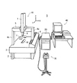
本実施形態に係る形状測定システムSは、図1に示すように、ワークWの表面を走査し、ワークWの各部の位置座標を測定する非接触式の光学式プローブ1を装着した三次元測定装置10と、三次元測定装置10を駆動制御すると共に、三次元測定装置10から必要な測定座標値を取り込むための駆動制御装置20と、駆動制御装置20を介して三次元測定装置10を手動操作するための操作盤30と、駆動制御装置20での測定手順を指示するパートプログラムを編集・実行すると共に、駆動制御装置20を介して取り込まれた測定座標値に幾何形状を当てはめるための計算を行ったり、パートプログラムを記録、送信したりする機能を備えたホストシステム40と、を備えて構成され、ワークWの表面形状を測定することができるようになっている。
As shown in FIG. 1, the shape measurement system S according to the present embodiment scans the surface of the workpiece W, and measures the position coordinates of each part of the workpiece W. The three-dimensional measurement is equipped with the non-contact
三次元測定装置10は、除振台2と、この除振台2の上に、その上面をベース面として水平面と一致するように載置された定盤3と、この定盤3の両側端から立設されたアーム支持体4a,4bと、このアーム支持体4a,4bの上端で支持されるX軸ガイド5と、を備えている。アーム支持体4aは、その下端がY軸駆動機構6によってY軸方向に駆動され、アーム支持体4bは、その下端がエアーベアリングによって定盤3上にY軸方向に移動可能に支持されている。X軸ガイド5には、垂直方向に延びるZ軸ガイド7がX軸ガイド5に沿ってX軸方向に移動可能に取り付けられている。Z軸ガイド7の下端部には、Z軸アーム8が設けられ、Z軸アーム8の下端に光学式プローブ1が装着されている。なお、光学式プローブ1は、水平面内に回転可能であっても良いし、この水平面と直交する垂直面内に回転可能であっても良い。
The three-
光学式プローブ1は、図2に示すように、本発明に係る光学装置としての光学部1Aと、本発明に係る測定手段としての測定部1Bと、を備えて構成されている。
光学部1Aは、レーザ光源11と、コリメータレンズ12と、ロッドレンズ13と、を備えて構成されている。
As shown in FIG. 2, the
The
レーザ光源11は、例えば、LD(Laser Diode)等で構成され、レーザ光を発生させて出射する。レーザ光源11から出射されたレーザ光は、下方に配置されたコリメータレンズ12に照射される。
The
コリメータレンズ12は、レーザ光源11から入射した光を平行光として、下方に配置されたロッドレンズ13に照射する。
The
ロッドレンズ13は、光形状変形手段として、コリメータレンズ12からの平行光をライン形状に変形させる。このロッドレンズ13に上方から平行光が照射されると、平行光はライン形状ビームに変形されて、下方に載置されたワークWに照射される。このロッドレンズ13は、詳しくは後述するが、レンズホルダ16とV溝ブロック17を有する光学系調整機構18に保持されている。
なお、レーザ光源11、コリメータレンズ12、及びロッドレンズ13は、光軸が同一となるように配置されている。
The
The
測定部1Bは、受光レンズ14と、CMOSイメージセンサ15と、を備えて構成されている。
The measuring
受光レンズ14は、ワークWの表面にて反射されたレーザ光を透過する。受光レンズ14を透過したレーザ光は、受光レンズ14と同一の光軸上に配置されたCMOSイメージセンサ15に入射される。
The
CMOSイメージセンサ15は、ワークWの表面にて反射されたレーザ光に基づいてワークWの画像を撮像し、ワークWの各部の座標値を測定する撮像素子であり、取得した測定座標値を、図示しない制御部等を介して駆動制御装置20に出力する。
The
次に、光学系調整機構18について詳細に説明する。
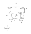
光学系調整機構18は、図3〜5に示すように、ロッドレンズ13を内部に保持するレンズホルダ16と、レンズホルダ16の上面部161に載置されるV溝ブロック17と、を備えて構成されている。
Next, the optical
As shown in FIGS. 3 to 5, the optical
レンズホルダ16は、例えば、外形が略直方体状に形成され、4つの側面部162a〜162dのうち対向する第1側面部162a及び第2側面部162c間を貫通するように形成した円形孔164から、円筒状のロッドレンズ13を嵌挿することで、内部にロッドレンズ13を保持することができるようになっている。
また、レンズホルダ16には、上面部161及び底面部163の略中央部分を貫通した円形孔165が形成されており、コリメータレンズ12から入射した平行光Cが、この円形孔165を通過することができるようになっている。レンズホルダ16の内部では、この円形孔165を覆うようにロッドレンズ13が保持されているため、コリメータレンズ12から入射した平行光Cは、円形孔165を通過する際、ロッドレンズ13によりライン形状ビームに変形されるようになっている。
The
Further, the
レンズホルダ16の上面部161は、直方体状に突起させた2つの突起部166a、166bを備えている。突起部166a、166bは、例えば、上面部161の長手方向の中央において幅方向両端部に、円形孔165を隔てて互いに対向するように設けられている。
The
また、レンズホルダ16の第1側面部162a及び第2側面部162cには、略U字状のU溝167a、167bが上面部161から底面部163に亘り形成されており、このU溝167a、167bに調整ネジ19、20が挿通できるようになっている。なお、調整ネジ19、20を挿通させる構成(第1のネジ孔)としてU溝167a、167bを例示したが、これに限定されるものではなく、調整ネジ19、20を底面部163から上面部161まで挿通させることが可能であればよい。例えば、U溝167a、167bの代わりに、上面部161及び底面部163の長手方向両端部を貫通した円形状のネジ孔を形成するようにしてもよい。
Further, substantially
V溝ブロック17は、外形が略円筒状に形成され、例えば、コリメータレンズ12の図示しない保持機構の下面に、上面部171を取り付けることができるように構成されている。
また、V溝ブロック17には、略中央部分に上面部171から底面部173に貫通した円形孔174が形成されており、コリメータレンズ12から入射した平行光Cが、この円形孔174を通過することができるようになっている。そして、円形孔174を通過した平行光Cは、レンズホルダ16に形成された円形孔165を通過することとなる。
The outer shape of the V-
The V-
V溝ブロック17の底面部173は、円形孔174を隔てて互いに対向するように2つの突出部175a、175bを備えている。突出部175a、175bは、それぞれ略中央部分に、円形孔174から周面部172にかけて第1のV溝であるV字状のV溝176a、176bが形成されている。このV溝176a、176bは、レンズホルダ16の突起部166a、166bと対向する位置に形成されており、レンズホルダ16の上面部161にV溝ブロック17を固定する際、レンズホルダ16の上面部161に設けられた突起部166a、166bに、V溝ブロック17の底面部173に設けられたV溝176a、176bが係合するようになっている。
The
また、V溝ブロック17の底面部173には、V溝176a、176b同士を結ぶ軸線と直交する軸線上において、当該V溝ブロック17の両端部に、円形孔174を隔てて互いに対向するように、上面部171まで貫通した第2のネジ孔である円形状のネジ孔177a、177bが形成されている。このV溝ブロック17のネジ孔177a、177bは、レンズホルダ16のネジ孔であるU溝167a、167bと対向する位置に形成されており、レンズホルダ16の上面部161から突出した調整ネジ19、20の先端部分は、このネジ孔177a、177bを挿通して螺合することとなる。なお、調整ネジ19、20は、それぞれ所望の位置(深さ)でネジ孔177a、177bと螺合することができるように構成されている。
The
次に、本実施形態の光学系調整機構18に係る作用について、図6を用いて説明する。
作業者は、光学系の調整に際して、例えば、レンズホルダ16の上面部161に設けられた突起部166a、166bに、V溝ブロック17の底面部173に設けられたV溝176a、176bが係合するようにV溝ブロック17を載置した状態で、レンズホルダ16の底面部163側から調整ネジ19、20をネジ孔であるU溝167a、167bに挿入し、レンズホルダ16の上面部161側から調整ネジ19、20の先端部分を突出させて、レンズホルダ16とV溝ブロック17とを固定する。
ここで、V溝ブロック17のネジ孔177a、177bは、レンズホルダ16のU溝167a、167bと対向する位置に形成されているため、レンズホルダ16の上面部161側から突出した調整ネジ19、20は、例えば、図6(A)に示すように、V溝ブロック17の底面部173側からネジ孔177a、177bに挿入されることとなる。
調整ネジ19、20は、それぞれ所望の位置でネジ孔177a、177bと螺合することができるように構成されており、例えば、図6(B)に示すように、左側の調整ネジ19を深い位置で締め、右側の調整ネジ20を浅い位置で締めるようにすると、レンズホルダ16の左側が上がった状態でV溝ブロック17と固定されることとなる。これにより、ロッドレンズ13は、光軸に対して左側が上がった状態で固定されることとなる。
一方、例えば、図6(C)に示すように、右側の調整ネジ20を深い位置で締め、左側の調整ネジ19を浅い位置で締めるようにすると、レンズホルダ16の右側が上がった状態でV溝ブロック17と固定されることとなる。これにより、ロッドレンズ13は、光軸に対して右側が上がった状態で固定されることとなる。
このように、左右両側の調整ネジ19、20の螺合位置を調整することで、光軸に対するロッドレンズ13の傾き具合を自在に調整することができるので、容易に光学系のアライメントを合わせることが可能となる。
Next, the effect | action which concerns on the optical
When the operator adjusts the optical system, for example, the
Here, since the
The adjustment screws 19 and 20 are configured to be able to be screwed into the
On the other hand, for example, as shown in FIG. 6C, when the
In this way, by adjusting the screwing positions of the adjustment screws 19 and 20 on both the left and right sides, the inclination of the
以上のように、本実施形態に係る光学式プローブ1の光学部1Aによれば、ロッドレンズ13を内部に保持するとともに、突起部166a、166bが形成されたレンズホルダ16と、レンズホルダ16に固定され、突起部166a、166bと対向する位置にV字状のV溝176a、176bが形成されたV溝ブロック17と、を有する光学系調整機構18を備え、レンズホルダ16にV溝ブロック17が固定される際、レンズホルダ16に設けられた突起部166a、166bに、V溝ブロック17に設けられたV溝176a、176bが係合する。
このため、レンズホルダ16に設けられた突起部166a、166bが、V溝ブロック17に設けられたV溝176a、176bに係合しつつ、突起部166a、166bとV溝176a、176bで自在に調整しながらV溝176a、176bとV溝ブロック17とを固定することができるので、光軸に対するロッドレンズ13の傾き具合を自在に調整することができ、容易に光学系のアライメントを合わせることが可能となる。
As described above, according to the
Therefore, the
また、本実施形態に係る光学式プローブ1の光学部1Aによれば、レンズホルダ16の長手方向両端部に、上面部161から底面部163に貫通したU溝167a、167bが形成され、V溝ブロック17には、U溝167a、167bと対向する位置に、ネジ孔177a、177bが形成され、調整ネジ19、20がレンズホルダ16の底面部163側からU溝167a、167bに挿入され、上面部161側から突出した調整ネジ19、20がネジ孔177a、177bに挿入されて螺合される。
このため、調整ネジ19、20の螺合位置を調整することで、光軸に対するロッドレンズ13の傾き具合を自在に調整することができるので、容易に光学系のアライメントを合わせることが可能となる。
Further, according to the
For this reason, by adjusting the screwing positions of the adjusting screws 19 and 20, the degree of inclination of the
<変形例>
実施形態では、V溝ブロック17の底面部173に設けられたV溝176a、176bに、レンズホルダ16の上面部161に設けた直方体状の突起部166a、166bを係合させることで、光軸に対するロッドレンズ13の傾き具合を自在に調整できるようにしているが、例えば、図7〜10に示すように、直方体状ではなく球面状に突起させた突起部を設けるようにしてもよい。
なお、説明の簡略化のため、実施形態と同様の構成については、同一の符号を付して、その詳細な説明を省略する。
<Modification>
In the embodiment, the rectangular
For simplification of description, the same reference numerals are given to the same configurations as those in the embodiment, and detailed description thereof is omitted.
即ち、図7に示す例では、レンズホルダ16の上面部161の幅方向両端部に、球体21a、21bを嵌合できる球面状の溝168a、168bを形成し、この溝168a、168bに球体21a、21bを嵌合させることにより球面状に突起させた突起部が形成されるようになっている。即ち、球体21a、21bが、突起部として機能することとなる。
これにより、例えば、図8に示すように、レンズホルダ16の上面部161に設けられた突起部(球体21a、21b)が、V溝ブロック17の底面部173に設けられたV溝176a、176bに係合する際に、突起部21a、21bの形状が球面状であるので、直方体状の突起部166a、166bと比べて、より滑らかにレンズホルダ16を移動させることができることとなって、光軸に対するロッドレンズ13の傾き具合をより精密に調整することが可能となる。
なお、ここでは、球面状の溝168a、168bに球体21a、21bを嵌合させることにより球面状に突起させた突起部を形成するようにしているが、これに限定されるものではなく、例えば、レンズホルダ16の上面部161の幅方向両端部に、少なくとも先端部が球面状の突起部(図示せず)を設けるようにしてもよい。
That is, in the example shown in FIG. 7,
Thus, for example, as shown in FIG. 8, the protrusions (
In this example, the
以上のように、図7に示す変形例に係る光学式プローブ1の光学部1Aによれば、突起部21a、21bの少なくとも先端部は、球面状であるので、直方体状の突起部166a、166bと比べて、より滑らかにレンズホルダ16を移動させることができることとなって、光軸に対するロッドレンズ13の傾き具合をより精密に調整することが可能となる。
As described above, according to the
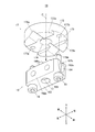
また、図9に示す例では、レンズホルダ16の上面部161の幅方向両端部に、円筒体22a、22bを係合可能な第2のV溝としてのV字状のV溝169a、169bを形成し、このV溝169a、169bに円筒体22a、22bを係合させることにより円筒状に突起させた突起部が形成されるようになっている。即ち、円筒体22a、22bが、突起部として機能することとなる。
これにより、例えば、図10(A)、(B)に示すように、レンズホルダ16の上面部161に設けられた突起部(円筒体22a、22b)が、V溝ブロック17の底面部173に設けられたV溝176a、176bに係合する際に、突起部22a、22bの形状が円筒状であるので、直方体状の突起部166a、166bと比べて、より滑らかにレンズホルダ16を移動させることができることとなって、光軸に対するロッドレンズ13の傾き具合をより精密に調整することが可能となる。また、レンズホルダ16の上面部161にV溝169a、169bを形成し、このV溝169a、169bに円筒体22a、22bを係合させるようにしたので、レンズホルダ16を移動させる際に、例えば図6に示したような調整ネジ19、20による調整機構を必要とせず、より簡易な構成で光学系のアライメントを合わせることが可能となる。
なお、ここでは、V字状のV溝169a、169bに円筒体22a、22bを係合させることにより円筒状に突起させた突起部を形成するようにしているが、これに限定されるものではなく、例えば、円筒体22a、22bの代わりに球体21a、21bを使用するようにしてもよい。この場合、特に図示はしないが、球体21a、21bがV溝169a、169bを伝って、外周面や円形孔165に落下することのないように、落下を防止する機構を設けるようにすることが好ましい。
In the example shown in FIG. 9, V-shaped
Accordingly, for example, as shown in FIGS. 10A and 10B, the protrusions (
In this example, the
以上のように、図9に示す変形例に係る光学式プローブ1の光学部1Aによれば、突起部22a、22bは、レンズホルダ16の上面部161に形成されたV字状のV溝169a、169bに円筒体22a、22bを係合させて構成される。
このため、直方体状の突起部166a、166bと比べて、より滑らかにレンズホルダ16を移動させることができることとなって、光軸に対するロッドレンズ13の傾き具合をより精密に調整することが可能となる。また、レンズホルダ16を移動させる際に、調整ネジ19、20による調整機構を必要とせず、より簡易な構成で光学系のアライメントを合わせることが可能となる。
As described above, according to the
Therefore, the
以上、本発明に係る実施形態に基づいて具体的に説明したが、本発明は上記実施形態に限定されるものではなく、その要旨を逸脱しない範囲で変更可能である。 As mentioned above, although concretely demonstrated based on embodiment which concerns on this invention, this invention is not limited to the said embodiment, It can change in the range which does not deviate from the summary.
例えば、上記実施形態では、光形状変形手段としてロッドレンズ13を例示して説明したが、これに限定されるものではなく、例えば、ロッドレンズ13の代わりにシリンドリカルレンズを使用するようにしてもよい。
For example, in the above embodiment, the
10 三次元測定装置
1 光学式プローブ(光学式測定装置)
1A 光学部(光学装置)
1B 測定部(測定手段)
11 レーザ光源
12 コリメータレンズ
13 ロッドレンズ(光形状変形手段)
14 受光レンズ
15 CMOSイメージセンサ
16 レンズホルダ(ホルダ)
161 上面部
162a〜d 側面部
163 底面部
166a、166b 突起部
167a、167b U溝(第1のネジ孔)
168a、168b 溝
169a、169b V溝(第2のV溝)
17 V溝ブロック
171 上面部
172 周面部
173 底面部
176a、176b V溝(第1のV溝)
177a、177b ネジ孔(第2のネジ孔)
18 光学系調整機構
19,20 調整ネジ
21a、21b 球体(突起部)
22a、22b 円筒体(突起部)
10 Three-
1A Optical part (optical device)
1B Measuring unit (measuring means)
11 Laser
14
161
168a,
17 V groove block 171
177a, 177b Screw hole (second screw hole)
18 Optical
22a, 22b Cylindrical body (projection)
Claims (3)
前記レーザ光源により出射されたレーザ光を平行光とするコリメータレンズと、
前記コリメータレンズにより平行光とされたレーザ光をライン形状の光に変形する光形状変形手段と、
を備える光学装置において、
前記光形状変形手段を内部に保持するとともに、突起部が形成されたホルダと、
前記ホルダに固定され、前記突起部と対向する位置にV字状の第1のV溝が形成されたV溝ブロックと、を有する光学系調整機構を備え、
前記ホルダに前記V溝ブロックが固定される際、前記ホルダに設けられた前記突起部に、前記V溝ブロックに設けられた前記第1のV溝が係合し、
前記突起部は、前記ホルダの上面部に形成されたV字状の第2のV溝に係合された円筒体により構成されることを特徴とする光学装置。 A laser light source for emitting laser light;
A collimator lens that collimates laser light emitted from the laser light source;
A light shape deforming means for transforming the laser light that has been converted into parallel light by the collimator lens into a line-shaped light;
In an optical device comprising:
While holding the light shape deformation means inside, a holder formed with a protrusion,
An optical system adjustment mechanism having a V-groove block fixed to the holder and having a V-shaped first V-groove formed at a position facing the protrusion.
When the V-groove block is fixed to the holder, the projecting portion provided on said holder, said first V-shaped groove provided in the V-groove block is engaged,
The protrusions optical device according to claim Rukoto constituted by engaged cylinder to the second V grooves of the formed V-shaped on the upper surface of the holder.
前記光形状変形手段により変形されたライン形状の光が照射された測定対象物からの反射光に基づいて、前記測定対象物の形状を測定する測定手段と、
を備えることを特徴とする光学式測定装置。 The optical device according to claim 1 or 2 ,
Measuring means for measuring the shape of the measurement object based on the reflected light from the measurement object irradiated with the light of the line shape deformed by the light shape deformation means;
An optical measurement device comprising:
Priority Applications (1)
| Application Number | Priority Date | Filing Date | Title |
|---|---|---|---|
| JP2011077412A JP5700540B2 (en) | 2011-03-31 | 2011-03-31 | Optical device and optical measuring device |
Applications Claiming Priority (1)
| Application Number | Priority Date | Filing Date | Title |
|---|---|---|---|
| JP2011077412A JP5700540B2 (en) | 2011-03-31 | 2011-03-31 | Optical device and optical measuring device |
Publications (2)
| Publication Number | Publication Date |
|---|---|
| JP2012212009A JP2012212009A (en) | 2012-11-01 |
| JP5700540B2 true JP5700540B2 (en) | 2015-04-15 |
Family
ID=47266033
Family Applications (1)
| Application Number | Title | Priority Date | Filing Date |
|---|---|---|---|
| JP2011077412A Active JP5700540B2 (en) | 2011-03-31 | 2011-03-31 | Optical device and optical measuring device |
Country Status (1)
| Country | Link |
|---|---|
| JP (1) | JP5700540B2 (en) |
Families Citing this family (6)
| Publication number | Priority date | Publication date | Assignee | Title |
|---|---|---|---|---|
| JP7056192B2 (en) * | 2018-02-05 | 2022-04-19 | コニカミノルタ株式会社 | Optical writing device and image forming device equipped with it |
| CN111307033B (en) * | 2018-12-12 | 2022-01-18 | 成都蒸汽巨人机器人科技有限公司 | Industrial robot depth vision sensor calibration board and calibration method |
| JP7344073B2 (en) | 2019-10-03 | 2023-09-13 | ギガフォトン株式会社 | optical device |
| JP7358188B2 (en) * | 2019-10-21 | 2023-10-10 | 株式会社ミツトヨ | Optical devices and optical measuring machines |
| CN110779488B (en) * | 2019-10-31 | 2021-06-22 | 湖北民族大学 | Self-adaptive measuring system for measuring distance of overall dimension parameters of steel and control method |
| CN111366092B (en) * | 2020-04-02 | 2021-02-02 | 易思维(杭州)科技有限公司 | Line structure light sensor pose adjusting method |
Family Cites Families (6)
| Publication number | Priority date | Publication date | Assignee | Title |
|---|---|---|---|---|
| JPH07190735A (en) * | 1993-12-27 | 1995-07-28 | Tosok Corp | Optical measuring device and its measuring method |
| JP3413308B2 (en) * | 1995-02-20 | 2003-06-03 | 株式会社リコー | Light source device for optical scanning device |
| JP2002221416A (en) * | 2001-01-25 | 2002-08-09 | Naokuni Sato | Line generator marking device |
| JP3081338U (en) * | 2001-01-26 | 2001-11-02 | 尚邦 佐藤 | Inking device |
| JP4526414B2 (en) * | 2005-03-03 | 2010-08-18 | 株式会社オーディオテクニカ | Laser line unit and laser marking device |
| JP2009015228A (en) * | 2007-07-09 | 2009-01-22 | Konica Minolta Business Technologies Inc | Print head mounted on image forming apparatus |
-
2011
- 2011-03-31 JP JP2011077412A patent/JP5700540B2/en active Active
Also Published As
| Publication number | Publication date |
|---|---|
| JP2012212009A (en) | 2012-11-01 |
Similar Documents
| Publication | Publication Date | Title |
|---|---|---|
| JP5700540B2 (en) | Optical device and optical measuring device | |
| CA2638919C (en) | Multi-beam optical probe and system for dimensional measurement | |
| JP4791118B2 (en) | Image measuring machine offset calculation method | |
| TW201423033A (en) | Shape measuring apparatus, structure manufacturing system, stage apparatus, shape measuring method, structure manufacturing method, program, and recording medium | |
| JP6288280B2 (en) | Surface shape measuring device | |
| JP2018169379A (en) | Irradiation device, laser marker, and method of adjusting irradiation device | |
| TWI421471B (en) | Laser head with laser head | |
| US10845182B2 (en) | Modular micro optics for optical probes | |
| JP4019995B2 (en) | Line indicator | |
| JP2001228382A (en) | Regulating method, assembling method and regulating device for multibeam light source unit, multibeam light source unit which is their object and image forming device having this multibeam light source unit | |
| JP2005156434A (en) | Lightwave interference measuring method using computer-generated hologram, and interferometric apparatus using same | |
| JP2002244018A (en) | Mechanism for adjusting distance and angle of mirror | |
| JP5606039B2 (en) | Stage device and wavefront aberration measuring device | |
| JP6786990B2 (en) | 3D shape measuring device | |
| JP2019058912A (en) | Laser processing head and laser processing device provided with the same | |
| JP4753657B2 (en) | Surface shape measuring apparatus and surface shape measuring method | |
| WO2013065418A1 (en) | Light source unit adjustment device calibration method and standard | |
| JP2007232629A (en) | Lens shape measuring instrument | |
| JPS63225108A (en) | Distance and inclination measuring instrument | |
| JP2005345329A (en) | Length-measuring laser interferometer | |
| CN112764184A (en) | Optical device and optical measuring machine | |
| JP5221211B2 (en) | Shape measuring device | |
| JP2018155836A (en) | Optical device | |
| WO2021220456A1 (en) | Processing system | |
| JP3886356B2 (en) | Attaching the optical fiber to the light emitting / receiving module |
Legal Events
| Date | Code | Title | Description |
|---|---|---|---|
| A621 | Written request for application examination |
Free format text: JAPANESE INTERMEDIATE CODE: A621 Effective date: 20140204 |
|
| A977 | Report on retrieval |
Free format text: JAPANESE INTERMEDIATE CODE: A971007 Effective date: 20141112 |
|
| A131 | Notification of reasons for refusal |
Free format text: JAPANESE INTERMEDIATE CODE: A131 Effective date: 20141125 |
|
| A521 | Request for written amendment filed |
Free format text: JAPANESE INTERMEDIATE CODE: A523 Effective date: 20150123 |
|
| TRDD | Decision of grant or rejection written | ||
| A01 | Written decision to grant a patent or to grant a registration (utility model) |
Free format text: JAPANESE INTERMEDIATE CODE: A01 Effective date: 20150210 |
|
| A61 | First payment of annual fees (during grant procedure) |
Free format text: JAPANESE INTERMEDIATE CODE: A61 Effective date: 20150212 |
|
| R150 | Certificate of patent or registration of utility model |
Ref document number: 5700540 Country of ref document: JP Free format text: JAPANESE INTERMEDIATE CODE: R150 |
|
| R250 | Receipt of annual fees |
Free format text: JAPANESE INTERMEDIATE CODE: R250 |
|
| R250 | Receipt of annual fees |
Free format text: JAPANESE INTERMEDIATE CODE: R250 |
|
| R250 | Receipt of annual fees |
Free format text: JAPANESE INTERMEDIATE CODE: R250 |