JP5686534B2 - Double-bearing reel rotation operation mechanism - Google Patents
Double-bearing reel rotation operation mechanism Download PDFInfo
- Publication number
- JP5686534B2 JP5686534B2 JP2010140745A JP2010140745A JP5686534B2 JP 5686534 B2 JP5686534 B2 JP 5686534B2 JP 2010140745 A JP2010140745 A JP 2010140745A JP 2010140745 A JP2010140745 A JP 2010140745A JP 5686534 B2 JP5686534 B2 JP 5686534B2
- Authority
- JP
- Japan
- Prior art keywords
- hole
- shaft
- handle
- handle arm
- protrusion
- Prior art date
- Legal status (The legal status is an assumption and is not a legal conclusion. Google has not performed a legal analysis and makes no representation as to the accuracy of the status listed.)
- Active
Links
- 230000007246 mechanism Effects 0.000 title claims description 68
- NJPPVKZQTLUDBO-UHFFFAOYSA-N novaluron Chemical compound C1=C(Cl)C(OC(F)(F)C(OC(F)(F)F)F)=CC=C1NC(=O)NC(=O)C1=C(F)C=CC=C1F NJPPVKZQTLUDBO-UHFFFAOYSA-N 0.000 claims description 44
- 230000009977 dual effect Effects 0.000 claims description 21
- 238000003825 pressing Methods 0.000 claims description 21
- 230000000149 penetrating effect Effects 0.000 claims description 3
- 230000035515 penetration Effects 0.000 claims 1
- 230000001105 regulatory effect Effects 0.000 claims 1
- 150000003839 salts Chemical class 0.000 description 13
- 230000006835 compression Effects 0.000 description 10
- 238000007906 compression Methods 0.000 description 10
- 230000005540 biological transmission Effects 0.000 description 9
- 238000004804 winding Methods 0.000 description 6
- 230000002265 prevention Effects 0.000 description 2
- 239000000956 alloy Substances 0.000 description 1
- 229910045601 alloy Inorganic materials 0.000 description 1
- 210000000078 claw Anatomy 0.000 description 1
- 238000005260 corrosion Methods 0.000 description 1
- 230000007797 corrosion Effects 0.000 description 1
- 230000008878 coupling Effects 0.000 description 1
- 238000010168 coupling process Methods 0.000 description 1
- 238000005859 coupling reaction Methods 0.000 description 1
- 238000000354 decomposition reaction Methods 0.000 description 1
- 238000004519 manufacturing process Methods 0.000 description 1
- 239000000463 material Substances 0.000 description 1
- 239000002184 metal Substances 0.000 description 1
- 238000000034 method Methods 0.000 description 1
- 230000002093 peripheral effect Effects 0.000 description 1
- 239000013535 sea water Substances 0.000 description 1
Images


Classifications
-
- A—HUMAN NECESSITIES
- A01—AGRICULTURE; FORESTRY; ANIMAL HUSBANDRY; HUNTING; TRAPPING; FISHING
- A01K—ANIMAL HUSBANDRY; CARE OF BIRDS, FISHES, INSECTS; FISHING; REARING OR BREEDING ANIMALS, NOT OTHERWISE PROVIDED FOR; NEW BREEDS OF ANIMALS
- A01K89/00—Reels
- A01K89/015—Reels with a rotary drum, i.e. with a rotating spool
- A01K89/0183—Drive mechanism details
-
- A—HUMAN NECESSITIES
- A01—AGRICULTURE; FORESTRY; ANIMAL HUSBANDRY; HUNTING; TRAPPING; FISHING
- A01K—ANIMAL HUSBANDRY; CARE OF BIRDS, FISHES, INSECTS; FISHING; REARING OR BREEDING ANIMALS, NOT OTHERWISE PROVIDED FOR; NEW BREEDS OF ANIMALS
- A01K89/00—Reels
- A01K89/015—Reels with a rotary drum, i.e. with a rotating spool
- A01K89/0192—Frame details
- A01K89/0193—Frame details with bearing features
-
- A—HUMAN NECESSITIES
- A01—AGRICULTURE; FORESTRY; ANIMAL HUSBANDRY; HUNTING; TRAPPING; FISHING
- A01K—ANIMAL HUSBANDRY; CARE OF BIRDS, FISHES, INSECTS; FISHING; REARING OR BREEDING ANIMALS, NOT OTHERWISE PROVIDED FOR; NEW BREEDS OF ANIMALS
- A01K89/00—Reels
- A01K89/015—Reels with a rotary drum, i.e. with a rotating spool
- A01K89/01931—Spool or spool shaft details
Landscapes
- Life Sciences & Earth Sciences (AREA)
- Environmental Sciences (AREA)
- Animal Husbandry (AREA)
- Biodiversity & Conservation Biology (AREA)
- Mechanical Control Devices (AREA)
Description
本発明は、回転操作機構、特に、両軸受リールのスプールを高低2速に切り換えて回転させるための両軸受リールの回転操作機構に関する。 The present invention is, rotation operation mechanism, in particular, it relates to a rotary operating mechanism for a dual bearing reel for rotating switches the dual-bearing reel spool high and low speed.
両軸受リールには、ハンドルの回転をスプールに伝達する回転伝達機構において、ハンドルの回転を高低2速に切り換え可能な変速機構を備えているものが知られている。(たとえば、特許文献1参照)。このような変速機構では、ハンドル軸の先端部に大径の高速ギア及び小径の低速ギアが選択的に一体回転可能に装着されている。また、この変速機構には、大径の高速ギアに噛合可能な小径のピニオンギア及び小径の低速ギアに噛合可能な大径のピニオンギアがスプール軸及びスプールに一体回転可能に装着されている。そして、操作軸の押圧操作により、ハンドル軸から高速ギアへの回転伝達をハンドル軸から低速ギアへの回転伝達に切り換えるようになっている。 2. Description of the Related Art A dual-bearing reel is known that includes a transmission mechanism that transmits the rotation of a handle to a spool and that has a speed change mechanism that can switch the rotation of the handle between high and low speeds. (For example, refer to Patent Document 1). In such a transmission mechanism, a large-diameter high-speed gear and a small-diameter low-speed gear are attached to the distal end portion of the handle shaft so as to be selectively rotatable integrally . In addition, a small-diameter pinion gear that can mesh with a large-diameter high-speed gear and a large-diameter pinion gear that can mesh with a small-diameter low-speed gear are attached to the speed change mechanism so as to rotate integrally with the spool shaft and the spool . By pressing operation of the operating shaft, it is adapted to switch the rotation transmission to a lower speed gear from the handle shaft rotation transmission to the high-speed gear from the handle axis.
ここでは、操作軸を内側に押し込むと、ハンドル軸から低速ギアに回転が伝達され、ハンドルの回転が低速ギアを介して大径のピニオンギアに伝達され、スプール軸及びスプールが低速回転する。一方、ハンドルアーム上に移動自在に配置されたロック部材を操作軸の係止溝から離反させる方向に移動操作することによって、操作軸が外側に引き出される。すると、ハンドル軸から高速ギアに回転が伝達され、ハンドルの回転が高速ギアを介して小径のピニオンギアに伝達され、スプール軸及びスプールが高速回転する。 Here, when the operating shaft is pushed inward, rotation is transmitted from the handle shaft to the low speed gear, rotation of the handle is transmitted to the large-diameter pinion gear via the low speed gear, and the spool shaft and the spool rotate at low speed. On the other hand, by moving operation in the direction of separating the movably arranged locking member on the handle arm from the locking groove of the operating shaft, the operating shaft is pull out to the outside. Then, rotation is transmitted from the handle shaft to the high speed gear, rotation of the handle is transmitted to the small-diameter pinion gear via the high speed gear, and the spool shaft and the spool rotate at high speed.
このような変速機構を操作する場合は、ハンドルアーム上に移動自在に配置されたロック部材を移動させることによって、操作軸を外側に引き出す(たとえば、非特許文献1参照)。 When operating such a transmission mechanism, by moving a movably arranged locking member on the handle arm, bring out the operating shaft on the outside (for example, see Non-Patent Document 1).
この種の操作機構は、板状の台座部材と、ロック部材と、コイルバネと、を有している。台座部材はハンドルアーム上に配置されている。ロック部材は、台座部材上に配置され先端部に設けられ釣人が指でつまんで移動操作するための操作つまみと、基端部が操作軸の係止溝に係止可能な係止部と、を有する。コイルバネは、台座部材に突出して形成された突出部に端部が係止され、ロック部材の係止部を操作軸の係止溝方向に付勢する。また、台座部材には、ロック部材を所定の方向に移動させるために、ロック部材をガイドするガイド溝が形成されている。 This type of operation mechanism includes a plate-shaped pedestal member, a lock member, and a coil spring. The base member is disposed on the handle arm . The lock member is disposed on the pedestal member, provided at the distal end portion , and an operation knob for a fisherman to pinch and move and operate, a locking portion whose base end portion can be locked in the locking groove of the operation shaft , having. The end of the coil spring is locked to a protruding portion formed to protrude from the pedestal member, and biases the locking portion of the lock member in the direction of the locking groove of the operation shaft . The pedestal member is formed with a guide groove for guiding the lock member in order to move the lock member in a predetermined direction.
前記従来の変速操作機構では、台座部材には、コイルばねの端部が係止される突出部と、ロック部材をガイドするガイド溝とが形成されているので、台座部材が凹凸になり、台座部材の形状が複雑になるおそれが生じる。このように台座部材の形状が複雑になると、台座部材を単純な形状の部材の組み合わせによって構成することが難しくなる。また、台座部材が凹凸になると、たとえば付着した海水から析出した塩が台座部材の凹凸に溜まりやすくなるとともに、溜まった塩を容易に分解して取り除くことが非常に困難になる。 In the conventional speed change operation mechanism, the pedestal member is formed with a protrusion that is engaged with the end of the coil spring and a guide groove that guides the lock member. The shape of the member may be complicated. When the shape of the pedestal member becomes complicated as described above, it is difficult to configure the pedestal member by a combination of simple shaped members. Further, when the pedestal member becomes uneven, for example, salt deposited from the attached seawater tends to accumulate in the unevenness of the pedestal member, and it becomes very difficult to easily decompose and remove the accumulated salt.
本発明の課題は、両軸受リールの回転を操作する機構において、台座部材を単純な形状の部材の組み合わせによって構成できるようにすることである。 An object of the present invention is to enable a base member to be configured by a combination of members having a simple shape in a mechanism for operating the rotation of a dual-bearing reel.
さらに、本発明の別の課題は、両軸受リールの回転を操作する機構において、台座部材に塩が溜まりにくくするとともに、溜まった塩を容易に分解して取り除くことができるようにすることである。 Furthermore, another object of the present invention is to make it difficult for salt to accumulate in the pedestal member and to easily disassemble and remove the accumulated salt in a mechanism for operating the rotation of the dual-bearing reel. .
発明1に係る両軸受リールの回転操作機構は、両軸受リールのスプールを高低2速に切り換えて回転させるための機構であって、ハンドルと、ハンドル軸と、操作軸と、台座部材と、ロック部材と、ロック部材付勢部材と、を備えている。ハンドルは、一端部に第1貫通孔が形成されるとともに第1突出部が表面に形成されたハンドルアームと、ハンドルアームの他端部に装着されたハンドル把手と、を有する。ハンドル軸は、先端部がハンドルアームの第1貫通孔に一体回転可能に装着され、軸方向に貫通する第2貫通孔を内部に有する。操作軸は、ハンドル軸の第2貫通孔に挿通され、被係合部を有する軸部と、軸部の一端に形成され高速と低速との間で切り換えるために押圧操作するための押圧操作部と、を有する。台座部材は、ハンドルアームの第1貫通孔と連通する第3貫通孔と、ハンドルアームの第1突出部が挿通する第4貫通孔と、を有し、ハンドルアームの表面に配置された板状の部材である。ロック部材は、台座部材の表面に沿って移動自在に配置され、操作軸の軸部の被係合部に係合可能な係合部と、ハンドルアームの第1突出部が移動可能に挿通するとともに第1突出部の移動を規制可能な第5貫通孔と、係合部を被係合部に係脱する操作を行う移動操作部と、を有する。
Rotation operation mechanism for a dual bearing reel according to the
この機構では、第1突出部がハンドルアームに形成され、ロック部材を移動規制する第5貫通孔がロック部材に形成されているので、従来のように台座部材に突出部やロック部材をガイドするガイド溝を形成する必要がなくなり、台座部材を板状に形成することができる。ここでは、台座部材を板状に形成することができるので、台座部材を単純な形状の部材の組み合わせによって構成することができる。さらに、ここでは、従来のように台座部材に突出部やロック部材をガイドするガイド溝を形成する必要がなくなるので、台座部材に凹凸がなくなることによって、台座部材に塩が溜まりにくくなるとともに、台座部材に塩が溜まったとしても溜まった塩を容易に分解して取り除くことができる。 In this machine structure, the first protrusion is formed on the handle arm, since the lock member 5 through hole movement restriction is formed in the lock member, prior protrusion and the locking member to the base member as It is not necessary to form a guide groove for guiding the pedestal, and the pedestal member can be formed in a plate shape. Here, since the pedestal member can be formed in a plate shape, the pedestal member can be configured by a combination of members having a simple shape. Further, since it is not necessary to form a guide groove for guiding the protrusion or the lock member on the pedestal member as in the prior art, the pedestal member has no irregularities, so that salt is less likely to accumulate on the pedestal member, and the pedestal Even if salt accumulates on the member, the accumulated salt can be easily decomposed and removed.
発明2に係る回転操作機構は、発明1の回転操作機構において、第5貫通孔に装着され、係合部が被係合部に係合する方向にロック部材を付勢するロック部材付勢部材をさらに備えている。台座部材の第4貫通孔は、ロック部材の第5貫通孔と連通可能に形成され、ロック部材付勢部材が装着される長穴である。この場合、たとえばロック部材の厚みを薄く形成し、ロック部材付勢部材の厚みがロック部材の厚みより大きい場合であっても、ロック部材付勢部材をロック部材の第5貫通孔及び台座部材の第4貫通孔に装着できる。
Rotary operation mechanism according to a second aspect is the rotation operation mechanism of the
発明3に係る回転操作機構は、発明2の回転操作機構において、台座部材は、ハンドルアームの第1突出部が挿通しかつロック部材付勢部材が装着される第6貫通孔を有する第1板状部材と、第1板状部材の裏面に固定されハンドルアームの第1突出部が挿通される第7貫通孔を有する第2板状部材と、を有している。この場合、貫通孔の形状が異なる第1板状部材と第2板状部材とを分割して形成することにより、第1板状部材及び第2板状部材をそれぞれ簡単なプレス加工で形成できる。
Rotary operation mechanism according to a third aspect is the rotation operation mechanism of the
発明4に係る回転操作機構は、発明1から3のいずれかの回転操作機構において、台座部材は、プレス加工により形成されている。この場合、簡単なプレス加工により、台座部材を安価かつ容易に製造できる。 Rotary operation mechanism according to a fourth aspect of the present invention is one of the rotation operation mechanism of the first to third aspects, the base member is formed by press working. In this case, the base member can be manufactured inexpensively and easily by simple press working.
発明5に係る回転操作機構は、発明1から4のいずれかの回転操作機構において、ロック部材の第5貫通孔は、ハンドルアームの第1突出部の外径より大きい幅となるように形成されている。この場合、第1突出部が第5貫通孔の側部に接触しないので、ロック部材の移動がスムーズになる。
Rotary operation mechanism according to the invention 5, in any of the rotational operation mechanism of the
発明6に係る回転操作機構は、発明1から5のいずれかの回転操作機構において、ハンドルアームは第2突出部を表面に有している。台座部材は、ハンドルアームの第2突出部が挿通する第8貫通孔をさらに有している。この場合、ハンドルアームの第1突出部を第4貫通孔に挿通し、ハンドルアームの第2突出部を第8貫通孔に挿通することにより、台座部材をハンドルアームに容易に位置決めできる。
Rotary operation mechanism according to the
発明7に係る回転操作機構は、発明6の回転操作機構において、ロック部材は、ハンドルアームの第2突出部が移動可能に挿通するとともに第2突出部の移動を規制可能な第9貫通孔をさらに有している。この場合、ハンドルアームの第1突出部を第5貫通孔に挿通し、ハンドルアームの第2突出部を第9貫通孔に挿通することにより、組み立て時に操作軸が挿入されていない状態でも、ロック部材を確実に移動規制することができる。
Rotary operation mechanism according to the
発明8に係る回転操作機構は、発明7の回転操作機構において、ロック部材の第9貫通孔は、ハンドルアームの第2突出部の外径より大きい幅となるように形成されている。この場合、第1突出部が第9貫通孔の側部に接触しないので、ロック部材の移動がスムーズになる。
Rotary operation mechanism according to the
発明9に係る回転操作機構は、発明1から8のいずれかの回転操作機構において、操作軸を軸方向外方に付勢する操作軸付勢部材をさらに備えている。 A rotation operation mechanism according to a ninth aspect of the present invention is the rotation operation mechanism according to any one of the first to eighth aspects, further comprising an operation shaft biasing member that biases the operation shaft outward in the axial direction.
本発明によれば、両軸受リールの回転操作機構において、台座部材を単純な形状の部材の組み合わせによって構成することができ、さらに、台座部材に塩が溜まりにくくなるとともに、台座部材に塩が溜まったとしても溜まった塩を容易に分解して取り除くことができる。 According to the present invention, Te rotational operation mechanism smell of dual-bearing reel, can be configured by a combination of simple shape member pedestal member, further, with the salt is less likely to accumulate in the base member, salt base member Even if accumulated, the accumulated salt can be easily decomposed and removed.
[全体構成]
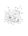
本発明の一実施形態を採用した両軸受リールは、図1及び図2に示すように、トローリングに用いられる大型の両軸受リールである。両軸受リールは、筒状のリール本体1と、リール本体1の中心部に回転自在に装着されたスプール軸2と、スプール軸2に回転自在かつ軸方向移動不能に支持されたスプール3と、リール本体1の側方に配置されたハンドル4と、を備えている。また、両軸受リールは、ハンドル4の回転をスプール3に伝達する回転伝達機構6と、高低2速に切り換え可能な変速操作機構8と、スプール3の糸繰り出し方向の回転を制動するレバードラグ機構7と、スプール3の糸繰り出し方向の回転を規制する逆転防止機構9と、をリール本体1の内部に備えている。
[overall structure]
A double-bearing reel employing an embodiment of the present invention is a large double-bearing reel used for trolling, as shown in FIGS. The dual-bearing reel includes a
[リール本体1]
リール本体1は、1対の第1及び第2側板10,11と、リールボディ12と、を有している。リールボディ12は、第1側板10及び第2側板11が両端に印籠結合により同芯に結合され、複数本の固定ねじにより固定されている。第1側板10及び第2側板11は、その略中心部で回動自在にスプール軸2の両端を支持する。
[Reel body 1]
The
リールボディ12と第1側板10及び第2側板11との間の上部には、リールハーネスに装着するためのハーネスラグ13が間隔を隔てて装着されている。リールボディ12の下部には、リールを釣竿に装着するための竿取付部14が設けられている。
A
[スプール軸2]
スプール軸2は、図2に示すように、両端に配置された1対の軸受31a,31bにより、リール本体1の第1側板10及び第2側板11に回転自在に支持されている。また、その内側で軸方向に間隔を隔てて配置された2つの軸受32a,32bにより、スプール3が回転自在に支持されている。
[Spool shaft 2]
As shown in FIG. 2, the
なお、スプール軸2の左端の軸受31aの内輪の右側には、図2に示すように、逆転防止機構9の後述するラチェットホイール50が当接している。また、スプール3を支持する左側の軸受32aの内輪の左側には、レバードラグ機構7の後述する摩擦ディスク26が当接している。
Note that the inner race of the right of the
[スプール3]
スプール3は、図2に示すように、糸巻胴部3aと、糸巻胴部3aの両端に一体形成されたフランジ部3bとを有している。
[Spool 3]
As shown in FIG. 2, the
[ハンドル4]
ハンドル4は、図2に示すように、筒状のハンドル軸5の突出端に固定されている。ハンドル軸5はスプール軸2の下方にスプール軸2と平行に配置されている。ハンドル軸5は、ボス部11aの下方において、2つの軸受33a,33bにより、リール本体1に回転自在に支持されている。ハンドル4は、図2から図5に示すように、ハンドルアーム4aと、ハンドル把手4bと、を有している。
[Handle 4]
As shown in FIG. 2, the
ハンドルアーム4aは、一端から他端に向けて延びる金属製の板状部材である。ハンドルアーム4aの一端部には非円形の貫通孔4c(第1貫通孔の一例)が形成され、他端部にハンドル把手4bが回転自在に装着されている。 The
ハンドルアーム4aの貫通孔4cには、ハンドル軸5を構成するナット部材23が一体回転可能に装着される。ハンドル軸5の先端部には、図3に示すように、貫通孔5b(第2貫通孔の一例)が形成されるとともに、貫通孔5bの内周部に雌ねじ部5aが形成されている。この雌ねじ部5aにナット部材23の雄ねじ部23aが螺合することによって、ハンドル軸5とナット部材23とが一体回転可能である。 A
ナット部材23は、外形が6角形の頭部23bを有しており、中央部には貫通孔23cが形成されている。 The
また、図4に示すように、ハンドルアーム4aの貫通孔4cの周囲の2箇所には、2つのねじ孔4fが形成され、さらに、貫通孔4cを挟んだ一方側及び他方側の2箇所には、それぞれ略円柱状の第1突出部4dと第2突出部4eとが突出して形成されている。 Further, as shown in FIG. 4, two
[回転伝達機構6]
回転伝達機構6は、図2及び図3に示すように、高速巻き取り用の第1メインギア16及び低速巻き取り用の第2メインギア17と、第1ピニオンギア18及び第2ピニオンギア19と、を有している。
[Rotation transmission mechanism 6]
As shown in FIGS. 2 and 3 , the
第1メインギア16及び第2メインギア17は、ハンドル4のハンドル軸5に回転自在に支持されている。第1ピニオンギア18及び第2ピニオンギア19は、第1メインギア16及び第2メインギア17にそれぞれ噛み合う状態でスプール軸2に回転自在に装着されている。
The first
第1ピニオンギア18は、図2に示すように、たとえば非磁性のステンレス合金等の耐蝕性を有する金属製の筒状部材である。第2ピニオンギア19は、第1ピニオンギア18と同様な材質の筒状部材である。
As shown in FIG. 2, the
[変速操作機構8]
変速操作機構8は、図2から図5に示すように、係合片20と、第1圧縮ばね21a(操作軸付勢部材の一例)と、第2圧縮ばね21bと、操作軸22と、ロック部材70と、ばね部材75(ロック部材付勢部材の一例)と、台座部材71と、ケース部材72とを有している。
[Speed change operation mechanism 8]
As shown in FIGS. 2 to 5, the speed
<係合片20> <
係合片20は、ハンドル軸5のスリット内に回転不能に配置され、第1メインギア16及び第2メインギア17のいずれか一方とハンドル軸5とを結合し、回転を伝達する。The
<第1圧縮ばね21a,第2圧縮ばね21b> <
第1圧縮ばね21aは、係合片20の図2左側に配置され、係合片20及び第2圧縮ばね21bを介して操作軸22を軸方向外方(図2右側)に付勢する。第2圧縮ばね21bは、係合片20の図2右側に配置され、係合片20を第2メインギア17側に付勢する。 The
<操作軸22> <
操作軸22は、係合片20の位置を、第1メインギア16に係合する高速位置(図2では、高速位置の係合片20を実線で示す)又は第2メインギア17に係合する低速位置に設定する。操作軸22は、図2に示すように、ハンドル軸5の貫通孔5bに挿通されている。操作軸22の図2右側の端部は、ハンドルアーム4aの軸方向外方(図2右側)に突出しており、操作軸22を図2左方向に押し込むことが可能である。操作軸22は、ハンドル軸5の突出端にねじ込まれたハンドル4をハンドル軸5に固定するためのナット部材23により軸方向に移動自在に支持されている。 The
操作軸22は、図2及び図3に示すように、ハンドルアーム4aの貫通孔4cに挿通されるボルト形状の軸部材であって、軸部22aと、軸部22aより大径の押圧操作部22bとを有している。
2 and 3, the
軸部22aは、図2に示すように、図2左側の先端部が第2圧縮ばね21bを介して係合片20を第2メインギア17側に押圧するように配置されている。軸部22aの軸方向外側の端部(図2右側)外周に被係合部22cを有している。被係合部22cは、軸部22aの外周に形成された係合溝であり、後述するロック部材70の湾曲部である係合部70cが係合可能である。軸部22aの中央部外周には、図2及び図3に示すように、環状溝22dが形成されており、環状溝22dには、操作軸22がハンドル軸5からハンドルアーム4a外方に飛び出さないようにするための2つのE型止め輪22eが装着されている。
As shown in FIG. 2, the
押圧操作部22bは、軸部22aの図2右側端に大径になるように形成され、釣人の押圧操作により高速と低速とに切り換えするための円形の押圧操作ボタンである。
The
<ロック部材70>
ロック部材70は、図2から図5に示すように、本体部70aと、移動操作部70bと、係合部70cと、貫通孔70d(第5貫通孔の一例)と、係止部70eと、貫通孔70f(第9貫通孔の一例)と、を有している。
<
As shown in FIGS. 2 to 5, the
本体部70aは、図4及び図5に示すように、板状の部材であり、台座部材71の表面に長手方向に沿うように移動自在に配置されている。 As shown in FIGS. 4 and 5, the main body portion 70 a is a plate-like member, and is disposed on the surface of the
移動操作部70bは、本体部70aの一端に設けられている。移動操作部70bは、図4及び図5に示すように、外形が略円形になるように形成されたつまみ部であって、釣人が指で摘みやすい形状となっており、このため、移動操作部70bの移動操作が行いやすくなる。移動操作部70bは、図4に示すように、ハンドルアーム4aの長手方向に沿うように移動可能に配置される。
The
係合部70cは、本体部70aの他端側に形成されており、側部が開口した略円形の貫通孔である。係合部70cには、操作軸22の軸部22aの被係合部22cが係合可能である。 The
貫通孔70dは、移動操作部70bと係合部70cとの間において、本体部70aの長手方向に沿って長く形成されている。貫通孔70dには、ハンドルアーム4aの第1突出部4dが挿通可能であり、貫通孔70dが形成された範囲で移動可能である。貫通孔70dにはばね部材75が装着されている。貫通孔70dは、ハンドルアーム4aの第1突出部4dの外径よりやや大きい幅となるように形成されている。 The through
係止部70eは、貫通孔70dの一端から他端側に延びて棒状に形成されている。係止部70eの周囲にばね部材75が装着されている。 The locking
貫通孔70fは、本体部70aの他端部において、本体部70aの他端から一端側に向かって形成されている。すなわち、貫通孔70fの一方の端部は開口している。この貫通孔70fに、ハンドルアーム4aの第2突出部4eが挿通可能である。貫通孔70fの端面に第2突出部4eが接触することにより、ロック部材70の移動が規制される。 The through
ばね部材75は、図4及び図5に示すように、ロック部材70を操作軸22方向に付勢するコイルばねであって、第1端部75aがハンドルアーム4aの第1突出部4dに接触するように配置され、第2端部75bが係止部70eに係止されるように貫通孔70dの内部に圧縮して配置されている。
4 and 5, the
<台座部材71及びばね部材75>
台座部材71は、図2から図5に示すように、ハンドルアーム4aの表面に長手方向に沿うように配置され、プレス加工により形成された板状部材である。台座部材71は、表面側にロック部材70の本体部70a及びばね部材75が移動自在に配置される台座であって、リテーナとしての機能を有している。台座部材71は、図4及び図5に示すように、貫通孔71a,71b,71dと、ねじ孔71cと、を有している。
<
As shown in FIGS. 2 to 5, the
貫通孔71a(第3貫通孔の一例)は、ハンドルアーム4aの貫通孔4cと連通し、ナット部材23の頭部23bがあらゆる位置で係合するように形成された内形が多角形の貫通孔である。この貫通孔71aには、操作軸22の軸部22aが移動自在に挿通される。貫通孔71b(第4貫通孔の一例)は、貫通孔71aの一方側において、ロック部材70の貫通孔70dと連通可能に長手方向に長く形成され、ハンドルアーム4aの第1突出部4dが挿通可能に貫通し、内部にばね部材75が装着される。ねじ孔71cは、貫通孔71aの周囲に配置され2つのねじ部材を挿通し台座部材71をハンドルアーム4aに固定する。貫通孔71d(第8貫通孔の一例)は、貫通孔71aの他方端側に配置され、ハンドルアーム4aの第2突出部4eが挿通可能である。
The through
台座部材71は、2つのねじ部材をねじ孔71cに装着することによって、ケース部材72とともにハンドルアーム4aの表面にねじ止めされている。
The
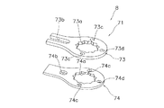
また、台座部材71は、図6に示すように、貫通孔の形状が異なる2つの第1台座部材73及び第2台座部材74で構成されており、第1台座部材73及び第2台座部材74をそれぞれ別々にプレス加工したものを接着して1つの部材にしている。
Further , as shown in FIG. 6 , the
第1台座部材73は、図6に示すように、貫通孔73a,73b,73dと、ねじ孔73cと、を有している。
As shown in FIG. 6, the
貫通孔73aは、ハンドルアーム4aの貫通孔4cと連通し、ナット部材23の頭部23bが係合する非円形孔である。貫通孔73b(第6貫通孔の一例)は、ハンドルアーム4aの第1突出部4dが挿通し、かつばね部材75が装着される長穴である。ねじ孔73cは、2つのねじ部材によって台座部材71をハンドルアーム4aに固定する。貫通孔73dはハンドルアーム4aの第2突出部4eが挿通可能である。
The through
第2台座部材74は、図6に示すように、貫通孔74a、74b,74dと、ねじ孔74cと、を有している。
As shown in FIG. 6, the
貫通孔74aは、ハンドルアーム4aの貫通孔4cと連通し、ナット部材23の頭部23bが係合する非円形孔である。貫通孔74b(第7貫通孔の一例)はハンドルアーム4aの第1突出部4dが挿通される略円形の貫通孔である。ねじ孔74cは2つのねじ部材によって台座部材71をハンドルアーム4aに固定する。貫通孔74dはハンドルアーム4aの第2突出部4eが挿通可能に貫通する。
The through
ここでは、第1台座部材73と第2台座部材74とを接着したときに、第1台座部材73と第2台座部材74との外形が完全に一致している。同様に、貫通孔73aと貫通孔74aとの外形が完全に一致し、2つのねじ孔73cと2つのねじ孔74cとの外形がそれぞれ完全に一致し、貫通孔73dと貫通孔74dとの外形が完全に一致している。また、貫通孔74dは、貫通孔73bの先端部と連通するように形成されており、貫通孔74d及び貫通孔73bにハンドルアーム4aの第1突出部4dが挿通される。
Here, when the
<ケース部材72>
ケース部材72は、図2から図5に示すように、ハンドルアーム4aの表面に固定され、操作軸22の押圧操作部22b及びロック部材70の移動操作部70bが外部に露出するように、操作軸22、ロック部材70、ばね部材75及び台座部材71を覆うカバー部材である。ケース部材72は、図4及び図5に示すように、押圧操作部22bが外方に露出する略円形の貫通孔72bと、2つのねじ部材を挿通しケース部材72を台座部材71とともにハンドルアーム4aに固定するための2つのねじ孔72cと、移動操作部70bが側部外方に露出する矩形の側孔72dと、を有している。略円形の貫通孔72bの周囲には、2つのねじ孔72cの一部にかかるように表面の一部が略円形に凹んだ凹部72aが形成されている。
<
As shown in FIGS. 2 to 5, the
[変速操作]
このようなロック部材70は、操作軸22の押圧操作部22bを押圧操作して操作軸22を図2左側に押し込むと、ロック部材70の係合部70cが操作軸22の被係合部22cに係合して操作軸22がロックされた状態となる。そして、ロック部材70の移動操作部70bを押す方向に移動操作すると、ロック部材70の係合部70cが操作軸22の被係合部22cから離反して操作軸22のロックが解除された状態となる。
[Shift operation]
When such a
このような構成の変速操作機構8では、操作軸22の押圧操作部22bを押圧操作して操作軸22を図2左側に押し込むと、第2メインギア17に係合片20が配置され、ハンドル4の回転が第2メインギア17を介して第2ピニオンギア19に伝達されスプール3が低速回転する。一方、ロック部材70の移動操作部70bを押す方向に移動操作し、ロック部材70の湾曲部である係合部70cを操作軸22の軸部22aに形成された環状溝である被係合部22cから離反する方向にロック解除して付勢力によって操作軸22を図2右側に引き出すと、第1メインギア16に係合片20が配置されハンドル4の回転が第1メインギア16を介して第1ピニオンギア18に伝達されスプール3が高速回転する。
In the speed
[他の機構]
レバードラグ機構7は、制動ディスク25と、摩擦板26aを有する摩擦ディスク26と、移動機構29とを有している。
[Other mechanisms]
逆転防止機構9は、ラチェットホイール50と、ラチェット爪51と、を有する爪式のものである。ラチェット爪51は、第1側板10の内側面に揺動自在に装着されており、引張ばねにより鋸歯を係止する側に付勢されている。
Conversely rotation prevention mechanism 9 includes a
摩擦ディスク26の外側は、図2に示すように、ドラグカバー41により覆われている。ドラグカバー41は、カバー本体41aと、取付部41bとを有している。
The outside of the
移動機構29は、図2に示すように、制動操作レバー45と、押圧機構46と、コイルばね47とを有している。
Moving
制動操作レバー45は、レバー部45aと、つまみ部45bと、を有している。レバー部45aの基端部は、押圧機構46を構成する第1カム部材60に回転不能に係止されている。押圧機構46は、第1カム部材60と、第2カム部材61と、押圧部材62と、を備えている。
[特徴]
このような両軸受リールの変速操作機構8では、台座部材71は、ハンドルアーム4aの第1突出部4dが挿通する貫通孔71bを有しており、ロック部材70は、ハンドルアーム4aの第1突出部4dが挿通し、ロック部材70を移動規制可能な貫通孔70dを有している。ここでは、ハンドルアーム4aに第1突出部4dが形成され、ロック部材70を移動規制する貫通孔70dがロック部材70に形成されているので、従来のように台座部材71に突出部やロック部材70をガイドするガイド溝を形成する必要がなくなる。
[Feature]
In the speed
ここでは、台座部材71を板状に形成することができるので、台座部材71を単純な形状の第1台座部材73と第2台座部材74との組み合わせによって構成することができる。さらに、ここでは、従来のように台座部材71に突出部やロック部材70をガイドするガイド溝を形成する必要がなくなるので、台座部材71に凹凸がなくなることによって、台座部材71に塩が溜まりにくくなるとともに、台座部材71に塩が溜まったとしても溜まった塩を容易に分解して取り除くことができる。
Here, since the
〔他の実施形態〕
(a) 前記実施形態では、中型のレバードラグリールを例にあげて説明したが、これに限られるものではなく、変速操作機構を有する両軸受リールであれば、あらゆる両軸受リールに本発明を適用できる。
Other Embodiment
(A) In the above embodiment, the medium-sized lever drag reel has been described as an example. However, the present invention is not limited to this, and the present invention can be applied to any dual-bearing reel as long as the dual-bearing reel has a speed change operation mechanism. Applicable.
(b) 前記実施形態では、台座部材71は、2つの第1台座部材73と第2台座部材74とで構成していたが、これに限定されるものではなく、1つの部材で台座部材71を成してもよい。
(B) In the said embodiment, although the
(c) 前記実施形態では、台座部材71は、プレス加工により形成されていたが、他の製造方法により台座部材71を加工してもよい。
(C) In the said embodiment, although the
(d) 前記実施形態では、ハンドル軸5の軸方向外側に高速巻き取り用の大径の第1メインギア16が配置され、ハンドル軸5の軸方向内側に低速巻き取り用の小径の第2メインギア17が配置されており、操作軸22の押圧操作部22bの押圧操作により高速から低速に切り替えるようにしていたが、ハンドル軸5の軸方向外側に低速巻き取り用の小径の第2メインギアを配置し、ハンドル軸5の軸方向内側に高速巻き取り用の大径の第1メインギアを配置することによって、操作軸22の押圧操作部22bの押圧操作により低速から高速に切り替える構成にしてもよい。
(D) In the above-described embodiment, the first
3 スプール
4 ハンドル
4a ハンドルアーム
4b ハンドル把手
4c (第1)貫通孔
4d 第1突出部
4e 第2突出部
5 ハンドル軸
5b (第2)貫通孔
6 回転伝達機構
8 変速操作機構
20 係合片
21a 第1圧縮ばね
21b 第2圧縮ばね
22 操作軸
22a 軸部
22b 押圧操作部
22c 被係合部
70 ロック部材
70b 移動操作部
70c 係合部
70d (第5)貫通孔
70e 係止部
70f (第9)貫通孔
71 台座部材
71a (第3)貫通孔
71b (第4)貫通孔
71d (第8)貫通孔
73 第1台座部材
73b (第6)貫通孔
74 第2台座部材
74b (第7)貫通孔
75 ばね部材
DESCRIPTION OF
Claims (9)
一端部に第1貫通孔(4c)が形成されるとともに第1突出部(4d)が表面に形成されたハンドルアーム(4a)と、前記ハンドルアーム(4a)の他端部に装着されたハンドル把手(4b)と、を有するハンドル(4)と、
先端部が前記ハンドルアーム(4)の第1貫通孔(4c)に一体回転可能に装着され、軸方向に貫通する第2貫通孔(5b)を内部に有するハンドル軸(5)と、
前記ハンドル軸(5)の第2貫通孔(5b)に挿通され、被係合部(22c)を有する軸部(22a)と、前記軸部(22a)の一端に形成され高速と低速との間で切り換えるために押圧操作するための押圧操作部(22b)と、を有する操作軸(22)と、
前記ハンドルアーム(4)の第1貫通孔(4c)と連通する第3貫通孔(71a)と、前記ハンドルアーム(4)の第1突出部(4d)が挿通する第4貫通孔(71b)と、を有し、前記ハンドルアーム(4)の表面に配置された板状の台座部材(71)と、
前記台座部材(71)の表面に沿って移動自在に配置され、前記操作軸(22)の軸部(22a)の被係合部(22c)に係合可能な係合部(70c)と、前記ハンドルアーム(4)の第1突出部(4d)が移動可能に挿通するとともに前記第1突出部(4d)の移動を規制可能な第5貫通孔(70d)と、前記係合部(70c)を前記被係合部(22c)に係脱する操作を行う移動操作部(70b)と、を有するロック部材(70)と、
前記第5貫通孔(70d)に装着され、前記係合部(70c)が前記被係合部(22c)に係合する方向に前記ロック部材(70)を付勢するロック部材付勢部材(75)と、
を備えた両軸受リールの回転操作機構。 A rotary operation mechanism for rotating the spool of a double-bearing reel by switching between high and low two speeds,
A handle arm (4a) having a first through hole (4c) formed at one end and a first protrusion (4d) formed on the surface, and a handle attached to the other end of the handle arm (4a) A handle (4) having a handle (4b);
A handle shaft (5) having a second through hole (5b) having a distal end portion rotatably attached to the first through hole (4c) of the handle arm (4) and penetrating in the axial direction;
A shaft portion (22a) that is inserted into the second through hole (5b) of the handle shaft (5) and has an engaged portion (22c), and formed at one end of the shaft portion (22a). An operating shaft (22) having a pressing operation part (22b) for pressing operation to switch between,
A third through hole (71a) communicating with the first through hole (4c) of the handle arm (4) and a fourth through hole (71b) through which the first protrusion (4d) of the handle arm (4) is inserted. And a plate-like pedestal member (71) disposed on the surface of the handle arm (4),
An engaging portion (70c) that is movably disposed along the surface of the pedestal member (71) and engageable with an engaged portion (22c) of the shaft portion (22a) of the operation shaft (22); A fifth through hole (70d) that allows the first protrusion (4d) of the handle arm (4) to be movably inserted and restricts movement of the first protrusion (4d), and the engagement portion (70c). ) And a moving operation portion (70b) for performing an operation of engaging and disengaging the engaged portion (22c),
A locking member urging member that is attached to the fifth through hole (70d) and urges the locking member (70) in a direction in which the engaging portion (70c) engages with the engaged portion (22c). 75)
A dual-bearing reel rotation operation mechanism equipped with
請求項1に記載の両軸受リールの回転操作機構。 The fourth through hole of the front Symbol seating member (71) (71b), said locking member (70) fifth through hole (70d) and communicating capable formed of, said locking member biasing member (75) is mounted Is a long hole,
The rotary operation mechanism of the dual-bearing reel according to claim 1.
前記ハンドルアーム(4)の第1突出部(4d)が挿通しかつ前記ロック部材付勢部材(75)が装着される第6貫通孔(73b)を有する第1板状部材(73)と、
前記第1板状部材(73)の裏面に固定され、前記ハンドルアーム(4)の第1突出部(4d)が挿通される第7貫通孔(74b)を有する第2板状部材(74)と、
を有している、
請求項1又は2に記載の両軸受リールの回転操作機構。 The pedestal member (71)
A first plate member (73) having a sixth through hole (73b) through which the first protrusion (4d) of the handle arm (4) is inserted and the lock member biasing member (75) is mounted;
A second plate member (74) having a seventh through hole (74b) fixed to the back surface of the first plate member (73) and through which the first protrusion (4d) of the handle arm (4) is inserted. When,
have,
The rotation operation mechanism of the dual-bearing reel according to claim 1 or 2.
前記台座部材(71)は、前記ハンドルアーム(4)の第2突出部(4e)が挿通する第8貫通孔(71d)をさらに有している、
請求項1から5のいずれか1項に記載の両軸受リールの回転操作機構。 The handle arm (4) has a second protrusion (4e) on its surface,
The base member (71) further includes an eighth through hole (71d) through which the second protrusion (4e) of the handle arm (4) is inserted.
The rotary operation mechanism of the dual-bearing reel according to any one of claims 1 to 5.
Priority Applications (7)
| Application Number | Priority Date | Filing Date | Title |
|---|---|---|---|
| JP2010140745A JP5686534B2 (en) | 2010-06-21 | 2010-06-21 | Double-bearing reel rotation operation mechanism |
| US13/049,258 US8534584B2 (en) | 2010-06-21 | 2011-03-16 | Dual-bearing reel speed change operation mechanism |
| SG2011021334A SG177051A1 (en) | 2010-06-21 | 2011-03-25 | Dual-bearing reel speed change operation mechanism |
| MYPI2011001423A MY157411A (en) | 2010-06-21 | 2011-03-31 | Dual-bearing reel speed change operation mechanism |
| TW100112316A TWI532429B (en) | 2010-06-21 | 2011-04-08 | Dual-bearing reel speed change operation mechanism |
| KR1020110035114A KR101746713B1 (en) | 2010-06-21 | 2011-04-15 | Dual-bearing reel speed change operation mechanism |
| CN201110167394.6A CN102283184B (en) | 2010-06-21 | 2011-06-21 | Dual-bearing reel speed change operation mechanism |
Applications Claiming Priority (1)
| Application Number | Priority Date | Filing Date | Title |
|---|---|---|---|
| JP2010140745A JP5686534B2 (en) | 2010-06-21 | 2010-06-21 | Double-bearing reel rotation operation mechanism |
Publications (3)
| Publication Number | Publication Date |
|---|---|
| JP2012000087A JP2012000087A (en) | 2012-01-05 |
| JP2012000087A5 JP2012000087A5 (en) | 2013-07-25 |
| JP5686534B2 true JP5686534B2 (en) | 2015-03-18 |
Family
ID=45327788
Family Applications (1)
| Application Number | Title | Priority Date | Filing Date |
|---|---|---|---|
| JP2010140745A Active JP5686534B2 (en) | 2010-06-21 | 2010-06-21 | Double-bearing reel rotation operation mechanism |
Country Status (7)
| Country | Link |
|---|---|
| US (1) | US8534584B2 (en) |
| JP (1) | JP5686534B2 (en) |
| KR (1) | KR101746713B1 (en) |
| CN (1) | CN102283184B (en) |
| MY (1) | MY157411A (en) |
| SG (1) | SG177051A1 (en) |
| TW (1) | TWI532429B (en) |
Families Citing this family (8)
| Publication number | Priority date | Publication date | Assignee | Title |
|---|---|---|---|---|
| US9307749B1 (en) * | 2012-05-16 | 2016-04-12 | Harout Alajajyan | Fishing reel speed control |
| ES1081005Y (en) * | 2013-05-21 | 2013-08-30 | Melian Correa Bernardo | FISHING REEL WITH TWO SPEEDS |
| JP6467218B2 (en) * | 2014-12-19 | 2019-02-06 | 株式会社シマノ | Double bearing reel |
| JP6530615B2 (en) * | 2015-02-26 | 2019-06-12 | 株式会社シマノ | Double bearing reel |
| CN107873662A (en) * | 2016-09-30 | 2018-04-06 | 宁波海宝渔具有限公司 | The two-axis winder of the fishing of variable-ratio |
| JP6784627B2 (en) * | 2017-03-27 | 2020-11-11 | グローブライド株式会社 | The handle of the fishing reel and the plate for that handle |
| US10624326B1 (en) * | 2019-05-29 | 2020-04-21 | Okuma Fishing Tackle Co., Ltd. | Gear shifting device of drum fishing reel |
| US11371796B1 (en) * | 2020-04-03 | 2022-06-28 | William J. Carpenter | Drag adjusting reel assembly |
Family Cites Families (15)
| Publication number | Priority date | Publication date | Assignee | Title |
|---|---|---|---|---|
| JPH0514780Y2 (en) * | 1987-04-11 | 1993-04-20 | ||
| JPH0822200B2 (en) * | 1989-08-25 | 1996-03-06 | 島野工業株式会社 | Reel with drag mechanism |
| JPH0739413Y2 (en) | 1989-11-06 | 1995-09-13 | 島野工業株式会社 | Double bearing reel gear shifting operation structure |
| JPH0460064U (en) * | 1990-09-25 | 1992-05-22 | ||
| US5058447A (en) * | 1990-11-30 | 1991-10-22 | Shimano Industrial Company Limited | Change-speed construction for fishing reel |
| JPH1014456A (en) * | 1996-07-04 | 1998-01-20 | Shimano Inc | Double-bearing trolling reel |
| US6360977B1 (en) * | 2000-05-26 | 2002-03-26 | Liang-Jen Chang | Change-speed construction for a fishing reel |
| US6325315B1 (en) * | 2000-06-01 | 2001-12-04 | Liang-Jen Chang | Change-speed construction for fishing reel |
| US7278599B2 (en) * | 2004-02-10 | 2007-10-09 | Harout Alajajyan | Double disc brake for brake pads of fishing reel |
| JP4334381B2 (en) * | 2004-03-25 | 2009-09-30 | 株式会社シマノ | Fishing reel, fishing information display device and fishing information display system |
| JP2006025763A (en) * | 2004-07-21 | 2006-02-02 | Shimano Inc | Handle-assembling body of fishing reel |
| US7234661B2 (en) * | 2004-07-21 | 2007-06-26 | Shimano Inc. | Drag adjustment device for a dual-bearing reel |
| JP4397043B2 (en) * | 2005-03-22 | 2010-01-13 | グローブライド株式会社 | Fishing reel |
| JP5047889B2 (en) * | 2008-06-19 | 2012-10-10 | グローブライド株式会社 | Fishing reel |
| JP5474428B2 (en) * | 2009-07-14 | 2014-04-16 | 株式会社シマノ | Double-bearing reel speed change mechanism |
-
2010
- 2010-06-21 JP JP2010140745A patent/JP5686534B2/en active Active
-
2011
- 2011-03-16 US US13/049,258 patent/US8534584B2/en active Active
- 2011-03-25 SG SG2011021334A patent/SG177051A1/en unknown
- 2011-03-31 MY MYPI2011001423A patent/MY157411A/en unknown
- 2011-04-08 TW TW100112316A patent/TWI532429B/en active
- 2011-04-15 KR KR1020110035114A patent/KR101746713B1/en active IP Right Grant
- 2011-06-21 CN CN201110167394.6A patent/CN102283184B/en active Active
Also Published As
| Publication number | Publication date |
|---|---|
| SG177051A1 (en) | 2012-01-30 |
| KR101746713B1 (en) | 2017-06-13 |
| US20110309177A1 (en) | 2011-12-22 |
| TW201206339A (en) | 2012-02-16 |
| US8534584B2 (en) | 2013-09-17 |
| KR20110139094A (en) | 2011-12-28 |
| CN102283184A (en) | 2011-12-21 |
| MY157411A (en) | 2016-06-15 |
| TWI532429B (en) | 2016-05-11 |
| JP2012000087A (en) | 2012-01-05 |
| CN102283184B (en) | 2014-12-24 |
Similar Documents
| Publication | Publication Date | Title |
|---|---|---|
| JP5686534B2 (en) | Double-bearing reel rotation operation mechanism | |
| JP2012000087A5 (en) | ||
| JP5324819B2 (en) | Lever drag reel reverse rotation prevention mechanism | |
| TWI504346B (en) | Dual bearing reel speed-change operation mechanism | |
| CN102405889B (en) | Dual-bearing reel | |
| TWI439229B (en) | Traverse camshaft for fishing reel and reciprocal movement mechanism for fishing reel employing the traverse camshaft | |
| JP2009273378A5 (en) | ||
| KR20110019714A (en) | Spinning reel spool coupling structure | |
| JP5481228B2 (en) | Fishing reel guide mechanism for spinning reel | |
| KR102002854B1 (en) | Handle assembly for spinning reel | |
| TWI454216B (en) | Drag adjusting device for dual-bearing reel | |
| JP2013202006A (en) | Fishing line guide mechanism of spinning reel and the spinning reel | |
| JP5805516B2 (en) | Double bearing reel | |
| JP5855954B2 (en) | Double bearing reel | |
| KR101126546B1 (en) | bait reel for fishing | |
| JP2013153659A5 (en) | ||
| JP2006025763A (en) | Handle-assembling body of fishing reel | |
| JP2006238727A (en) | Fishing reel | |
| JP6247115B2 (en) | Spinning reel | |
| JP4963201B2 (en) | Spinning reel spool | |
| JP2015159757A5 (en) | ||
| JP6748598B2 (en) | Dual bearing reel with sounding mechanism | |
| KR20110019701A (en) | Brake device for spinning reel rotor | |
| JP2011041560A (en) | Rotor brake of spinning reel | |
| TWI763961B (en) | Dual-bearing reel |
Legal Events
| Date | Code | Title | Description |
|---|---|---|---|
| A521 | Request for written amendment filed |
Free format text: JAPANESE INTERMEDIATE CODE: A523 Effective date: 20130612 |
|
| A621 | Written request for application examination |
Free format text: JAPANESE INTERMEDIATE CODE: A621 Effective date: 20130612 |
|
| A131 | Notification of reasons for refusal |
Free format text: JAPANESE INTERMEDIATE CODE: A131 Effective date: 20140812 |
|
| A521 | Request for written amendment filed |
Free format text: JAPANESE INTERMEDIATE CODE: A523 Effective date: 20140829 |
|
| A131 | Notification of reasons for refusal |
Free format text: JAPANESE INTERMEDIATE CODE: A131 Effective date: 20141007 |
|
| A521 | Request for written amendment filed |
Free format text: JAPANESE INTERMEDIATE CODE: A523 Effective date: 20141202 |
|
| TRDD | Decision of grant or rejection written | ||
| A01 | Written decision to grant a patent or to grant a registration (utility model) |
Free format text: JAPANESE INTERMEDIATE CODE: A01 Effective date: 20141224 |
|
| A61 | First payment of annual fees (during grant procedure) |
Free format text: JAPANESE INTERMEDIATE CODE: A61 Effective date: 20150120 |
|
| R150 | Certificate of patent or registration of utility model |
Ref document number: 5686534 Country of ref document: JP Free format text: JAPANESE INTERMEDIATE CODE: R150 |
|
| R250 | Receipt of annual fees |
Free format text: JAPANESE INTERMEDIATE CODE: R250 |
|
| R250 | Receipt of annual fees |
Free format text: JAPANESE INTERMEDIATE CODE: R250 |
|
| R250 | Receipt of annual fees |
Free format text: JAPANESE INTERMEDIATE CODE: R250 |
|
| R250 | Receipt of annual fees |
Free format text: JAPANESE INTERMEDIATE CODE: R250 |
|
| R250 | Receipt of annual fees |
Free format text: JAPANESE INTERMEDIATE CODE: R250 |
|
| R250 | Receipt of annual fees |
Free format text: JAPANESE INTERMEDIATE CODE: R250 |
|
| R250 | Receipt of annual fees |
Free format text: JAPANESE INTERMEDIATE CODE: R250 |