JP2012000087A5 - - Google Patents
Download PDFInfo
- Publication number
- JP2012000087A5 JP2012000087A5 JP2010140745A JP2010140745A JP2012000087A5 JP 2012000087 A5 JP2012000087 A5 JP 2012000087A5 JP 2010140745 A JP2010140745 A JP 2010140745A JP 2010140745 A JP2010140745 A JP 2010140745A JP 2012000087 A5 JP2012000087 A5 JP 2012000087A5
- Authority
- JP
- Japan
- Prior art keywords
- hole
- shaft
- handle
- handle arm
- spool
- Prior art date
- Legal status (The legal status is an assumption and is not a legal conclusion. Google has not performed a legal analysis and makes no representation as to the accuracy of the status listed.)
- Granted
Links
Images


Description
本発明は、変速操作機構、特に、ハンドルの回転を高低2速に切り換えてスプールに伝達可能な両軸受リールの変速操作機構に関する。 The present invention relates to a speed change operation mechanism, and more particularly to a speed change operation mechanism for a dual-bearing reel capable of transmitting a handle to a spool by switching the rotation of the handle to high and low speeds.
両軸受リールには、ハンドルの回転をスプールに伝達する回転伝達機構において、ハンドルの回転を高低2速に切り換え可能な変速機構を備えているものが知られている。(たとえば、特許文献1参照)。このような変速機構では、ハンドル軸の先端部に大径の高速ギア及び小径の低速ギアが選択的に一体回転可能に装着され、大径の高速ギアに噛合可能な小径のピニオンギア及び小径の低速ギアに噛合可能な大径のピニオンギアがスプール軸及びスプールに一体回転可能に装着され、操作軸の押圧操作によりハンドル軸から高速ギアへの回転伝達をハンドル軸から低速ギアへの回転伝達に切り換えるようになっている。ここでは、操作軸を内側に押し込むと、ハンドル軸から低速ギアに回転伝達することによって、ハンドルの回転が低速ギアを介して大径のピニオンギアに伝達され、スプール軸及びスプールが低速回転する。一方、ハンドルアーム上に移動自在に配置されたロック部材を操作軸の係止溝から離反させる方向に移動操作することによって操作軸を外側に引き出すと、ハンドル軸から高速ギアに回転伝達することによって、ハンドルの回転が高速ギアを介して小径のピニオンギアに伝達され、スプール軸及びスプールが高速回転する。 2. Description of the Related Art A dual-bearing reel is known that includes a transmission mechanism that transmits the rotation of a handle to a spool and that has a speed change mechanism that can switch the rotation of the handle between high and low speeds. (For example, refer to Patent Document 1). In such a transmission mechanism, a large-diameter high-speed gear and a small-diameter low-speed gear are selectively attached to the tip of the handle shaft so as to be integrally rotatable, and a small-diameter pinion gear and a small-diameter gear that can mesh with the large-diameter high-speed gear. A large-diameter pinion gear that can be meshed with the low-speed gear is mounted on the spool shaft and the spool so that it can rotate integrally, and by rotating the operation shaft, the rotation transmission from the handle shaft to the high-speed gear is changed to the rotation transmission from the handle shaft to the low-speed gear. It is designed to switch. Here, when the operating shaft is pushed inward, rotation of the handle shaft is transmitted to the low-speed gear, whereby the rotation of the handle is transmitted to the large-diameter pinion gear via the low-speed gear, and the spool shaft and the spool rotate at low speed. On the other hand, when the operation shaft is pulled out by moving the lock member movably disposed on the handle arm in a direction away from the locking groove of the operation shaft, the rotation is transmitted from the handle shaft to the high speed gear. The rotation of the handle is transmitted to the small-diameter pinion gear via the high speed gear, and the spool shaft and the spool rotate at high speed.
このような変速操作機構は、ハンドルアーム上に移動自在に配置されたロック部材を操作軸の係止溝から離反させる方向に移動操作することによって、操作軸を外側に引き出すようになっている(たとえば、非特許文献1参照)。この種の変速操作機構は、ハンドルアーム上に配置された板状の台座部材(リテーナ)と、台座部材上に配置され先端部に設けられ釣人が指でつまんで移動操作するための操作つまみと基端部が操作軸の係止溝に係止可能な係止部とを有する板状のロック部材(ロックプレート)と、台座部材に突出して形成された突出部に端部が係止されロック部材の係止部を操作軸の係止溝方向に付勢するコイルばねとを有している。また、台座部材には、ロック部材を所定の方向に移動させるためにロック部材をガイドするガイド溝が形成されている。 In such a speed change operation mechanism, the operation shaft is pulled out by moving the lock member, which is movably disposed on the handle arm, in a direction away from the locking groove of the operation shaft. For example, refer nonpatent literature 1). This type of speed change operation mechanism includes a plate-like pedestal member (retainer) disposed on a handle arm, an operation knob disposed on the pedestal member and provided at a tip portion for a fisherman to pinch and move the finger. A plate-shaped lock member (lock plate) having a base end portion that can be locked in the locking groove of the operation shaft, and a protruding portion formed to protrude from the pedestal member are locked by locking the end portion. A coil spring that urges the locking portion of the member in the direction of the locking groove of the operation shaft. The pedestal member is formed with a guide groove for guiding the lock member in order to move the lock member in a predetermined direction.
前記従来の変速操作機構では、台座部材には、コイルばねの端部が係止される突出部と、ロック部材をガイドするガイド溝とが形成されているので、台座部材が凹凸になり、台座部材の形状が複雑になるおそれが生じる。このように台座部材の形状が複雑になると、台座部材を単純な形状の部材の組み合わせによって構成することが難しくなる。また、台座部材が凹凸になると、たとえば付着した海水から析出した塩が台座部材の凹凸に溜まりやすくなるとともに、溜まった塩を容易に分解して取り除くことが非常に困難になる。 In the conventional speed change operation mechanism, the pedestal member is formed with a protrusion that is engaged with the end of the coil spring and a guide groove that guides the lock member. The shape of the member may be complicated. When the shape of the pedestal member becomes complicated as described above, it is difficult to configure the pedestal member by a combination of simple shaped members. Further, when the pedestal member becomes uneven, for example, salt deposited from the attached seawater tends to accumulate in the unevenness of the pedestal member, and it becomes very difficult to easily decompose and remove the accumulated salt.
本発明の課題は、両軸受リールの変速操作機構において、台座部材を単純な形状の部材の組み合わせによって構成できるようにすることである。さらに、本発明の別の課題は、両軸受リールの変速操作機構において、台座部材に塩が溜まりにくくするとともに、溜まった塩を容易に分解して取り除くことができるようにすることである。 An object of the present invention is to enable a pedestal member to be configured by a combination of members having a simple shape in a dual-bearing reel speed change operation mechanism. Further, another object of the present invention is to make it difficult for salt to accumulate in the base member and to easily disassemble and remove the accumulated salt in the shift operation mechanism of the dual-bearing reel.
発明1に係る両軸受リールの変速操作機構は、ハンドルの回転を高低2速に切り換えてスプールに伝達可能な両軸受リールの変速操作機構であって、ハンドルと、ハンドル軸と、操作軸と、操作軸付勢部材と、台座部材と、ロック部材と、ロック部材付勢部材とを備えている。ハンドルは、長手方向と交差する方向に貫通する第1貫通孔と長手方向と交差する方向の表面側に突出する第1突出部とが形成されたハンドルアームと、ハンドルアームの先端部に装着されたハンドル把手とを有する。ハンドル軸は、基端部がハンドルアームの第1貫通孔に一体回転可能に装着され、内部を軸方向に貫通する第2貫通孔を有する。操作軸は、ハンドル軸の第2貫通孔に挿通され、基端部外周に被係合部を有する軸部と、軸部の基端側に大径になるように形成され押圧操作により高速から低速にまたは低速から高速に切り換え可能な押圧操作部とを有する。操作軸付勢部材は、操作軸を軸方向外方に付勢する部材である。台座部材は、ハンドルアームの表面に長手方向に沿うように配置され、ハンドルアームの第1貫通孔と連通する第3貫通孔と、ハンドルアームの第1突出部が挿通可能に貫通する第4貫通孔とを有する板状の部材である。ロック部材は、台座部材の表面に長手方向に沿うように移動自在に配置され、操作軸の軸部の被係合部に係合可能な係合部と、ハンドルアームの第1突出部が挿通可能かつ先端側に接触して移動規制可能に長手方向に長く形成された第5貫通孔と、第5貫通孔の基端側に形成された係止部と、係合部を被係合部に係脱するために移動操作を行う移動操作部とを有する。ロック部材付勢部材は、一端がハンドルアームの第1突出部に係止され他端がロック部材の係止部に係止されるようにロック部材の第5貫通孔に装着され、ロック部材を係合部が被係合部に係合する方向に付勢する部材である。 A dual-bearing reel shift operation mechanism according to a first aspect of the present invention is a dual-bearing reel shift operation mechanism capable of switching the rotation of a handle between high and low speeds and transmitting it to a spool, the handle, a handle shaft, an operation shaft, An operation shaft biasing member, a pedestal member, a lock member, and a lock member biasing member are provided. The handle is attached to a handle arm formed with a first through hole penetrating in a direction intersecting the longitudinal direction and a first projecting portion projecting to the surface side in a direction intersecting the longitudinal direction, and a distal end portion of the handle arm. And a handle handle. The handle shaft has a base end portion that is attached to the first through hole of the handle arm so as to be integrally rotatable, and has a second through hole that penetrates the inside in the axial direction. The operation shaft is inserted into the second through hole of the handle shaft, and is formed with a shaft portion having an engaged portion on the outer periphery of the base end portion and a large diameter on the base end side of the shaft portion. A pressing operation unit that can be switched to a low speed or from a low speed to a high speed. The operation shaft urging member is a member that urges the operation shaft outward in the axial direction. The pedestal member is disposed along the longitudinal direction on the surface of the handle arm, and has a third through hole communicating with the first through hole of the handle arm, and a fourth penetration through which the first protrusion of the handle arm can be inserted. It is a plate-shaped member having a hole. The lock member is movably disposed along the longitudinal direction on the surface of the pedestal member, and the engaging portion engageable with the engaged portion of the shaft portion of the operation shaft and the first protruding portion of the handle arm are inserted therethrough. A fifth through hole formed in the longitudinal direction so as to be capable of restricting movement while being in contact with the distal end side, a locking part formed on the base end side of the fifth through hole, and an engaging part as an engaged part And a moving operation unit that performs a moving operation to disengage from and disengage. The lock member urging member is attached to the fifth through hole of the lock member so that one end is locked to the first protruding portion of the handle arm and the other end is locked to the lock portion of the lock member. It is a member that urges the engaging portion in a direction to engage the engaged portion.
この変速操作機構では、台座部材は、ハンドルアームの第1突出部が挿通可能に貫通する第4貫通孔を有しており、ロック部材は、ハンドルアームの第1突出部が挿通可能かつ先端側に接触してロック部材を移動規制可能に長手方向に長く形成された第5貫通孔を有している。ここでは、第1突出部がハンドルアームに形成され、ロック部材を移動規制する第5貫通孔がロック部材に形成されているので、従来のように台座部材に突出部やロック部材をガイドするガイド溝を形成する必要がなくなり、台座部材を板状に形成することができる。ここでは、台座部材を板状に形成することができるので、台座部材を単純な形状の部材の組み合わせによって構成することができる。さらに、ここでは、従来のように台座部材に突出部やロック部材をガイドするガイド溝を形成する必要がなくなるので、台座部材に凹凸がなくなることによって、台座部材に塩が溜まりにくくなるとともに、台座部材に塩が溜まったとしても溜まった塩を容易に分解して取り除くことができる。 In this speed change operation mechanism, the pedestal member has a fourth through hole through which the first protrusion of the handle arm can be inserted, and the lock member can be inserted through the first protrusion of the handle arm. The fifth through hole is formed to be long in the longitudinal direction so that the movement of the lock member can be regulated by contacting the lock member. Here, since the first protrusion is formed in the handle arm and the fifth through hole for restricting the movement of the lock member is formed in the lock member, the guide for guiding the protrusion and the lock member to the base member as in the prior art. It is not necessary to form a groove, and the pedestal member can be formed in a plate shape. Here, since the pedestal member can be formed in a plate shape, the pedestal member can be configured by a combination of members having a simple shape. Further, since it is not necessary to form a guide groove for guiding the protrusion or the lock member on the pedestal member as in the prior art, the pedestal member has no irregularities, so that salt is less likely to accumulate on the pedestal member, and the pedestal Even if salt accumulates on the member, the accumulated salt can be easily decomposed and removed.
発明2に係る変速操作機構は、発明1の変速操作機構において、台座部材の第4貫通孔は、ロック部材の第5貫通孔と連通可能に長手方向に長く形成され、ロック部材付勢部材が装着される長穴である。この場合、たとえばロック部材の厚みを薄く形成し、ロック部材付勢部材の厚みがロック部材の厚みより大きい場合であっても、ロック部材付勢部材をロック部材の第5貫通孔及び台座部材の第4貫通孔に装着できる。 A speed change operation mechanism according to a second aspect of the present invention is the speed change operation mechanism according to the first aspect, wherein the fourth through hole of the base member is formed long in the longitudinal direction so as to be able to communicate with the fifth through hole of the lock member, and the lock member biasing member is It is a long hole to be installed. In this case, for example, even if the thickness of the lock member is thin and the thickness of the lock member urging member is larger than the thickness of the lock member, the lock member urging member is connected to the fifth through hole of the lock member and the base member. It can be attached to the fourth through hole.
発明3に係る変速操作機構は、発明2の変速操作機構において、台座部材は、ハンドルアームの第1突出部が挿通しかつロック部材付勢部材が装着される第6貫通孔を有する第1板状部材と、第1板状部材の裏面に固定されハンドルアームの第1突出部が挿通される第7貫通孔を有する第2板状部材とを有している。この場合、貫通孔の形状が異なる第1板状部材と第2板状部材とを分割して形成することにより、第1板状部材及び第2板状部材をそれぞれ簡単なプレス加工で形成できる。 A speed change operation mechanism according to a third aspect of the present invention is the speed change operation mechanism according to the second aspect, wherein the pedestal member has a first through hole through which the first protrusion of the handle arm is inserted and a lock member biasing member is mounted. And a second plate member having a seventh through hole that is fixed to the back surface of the first plate member and through which the first protrusion of the handle arm is inserted. In this case, the first plate member and the second plate member having different through-hole shapes can be formed separately to form the first plate member and the second plate member by simple press processing. .
発明4に係る変速操作機構は、発明1から3のいずれかの変速操作機構において、台座部材は、プレス加工により形成されている。この場合、簡単なプレス加工により、台座部材を安価かつ容易に製造できる。 A speed change operation mechanism according to a fourth aspect of the present invention is the speed change operation mechanism according to any one of the first to third aspects, wherein the base member is formed by pressing. In this case, the base member can be manufactured inexpensively and easily by simple press working.
発明5に係る変速操作機構は、発明1から4のいずれかの変速操作機構において、ロック部材の第5貫通孔は、ハンドルアームの第1突出部の外径よりやや大きい幅となるように形成されている。この場合、第1突出部が第5貫通孔の側部に接触しないので、ロック部材の移動がスムーズになる。 A speed change operation mechanism according to a fifth aspect of the present invention is the speed change operation mechanism according to any one of the first to fourth aspects, wherein the fifth through hole of the lock member is formed to have a width that is slightly larger than the outer diameter of the first protrusion of the handle arm. Has been. In this case, since the first protruding portion does not contact the side portion of the fifth through hole, the movement of the lock member becomes smooth.
発明6に係る変速操作機構は、発明1から5のいずれかの変速操作機構において、ハンドルアームは、長手方向と交差する方向の表面側に突出するように形成された第2突出部をさらに有している。台座部材は、ハンドルアームの第2突出部が挿通可能に貫通する第8貫通孔をさらに有している。この場合、ハンドルアームの第1突出部を第4貫通孔に挿通し、ハンドルアームの第2突出部を第8貫通孔に挿通することにより、台座部材をハンドルアームに容易に位置決めできる。 A shift operation mechanism according to a sixth aspect of the present invention is the shift operation mechanism according to any one of the first to fifth aspects, wherein the handle arm further includes a second protrusion formed so as to protrude to the surface side in a direction intersecting the longitudinal direction. doing. The pedestal member further has an eighth through hole through which the second protrusion of the handle arm can be inserted. In this case, the base member can be easily positioned on the handle arm by inserting the first protrusion of the handle arm through the fourth through hole and the second protrusion of the handle arm through the eighth through hole.
発明7に係る変速操作機構は、発明6の変速操作機構において、ロック部材は、ハンドルアームの第2突出部が挿通可能かつ基端側に接触して移動規制可能に長手方向に長く形成された第9貫通孔をさらに有している。この場合、ハンドルアームの第1突出部を第5貫通孔に挿通し、ハンドルアームの第2突出部を第9貫通孔に挿通することにより、組み立て時に操作軸が挿入されていない状態でも、ロック部材を確実に移動規制することができる。 According to a seventh aspect of the present invention, there is provided the speed change operation mechanism according to the sixth aspect, wherein the lock member is formed long in the longitudinal direction so that the second projecting portion of the handle arm can be inserted and contacted with the base end side so that movement can be restricted. It further has a ninth through hole. In this case, the first protrusion of the handle arm is inserted into the fifth through hole, and the second protrusion of the handle arm is inserted into the ninth through hole, so that the lock can be locked even when the operation shaft is not inserted during assembly. The movement of the member can be surely restricted.
発明8に係る変速操作機構は、発明7の変速操作機構において、ロック部材の第9貫通孔は、ハンドルアームの第2突出部の外径よりやや大きい幅となるように形成されている。この場合、第1突出部が第9貫通孔の側部に接触しないので、ロック部材の移動がスムーズになる。 The shift operation mechanism according to an eighth aspect of the present invention is the shift operation mechanism according to the seventh aspect, wherein the ninth through hole of the lock member is formed to have a width that is slightly larger than the outer diameter of the second protruding portion of the handle arm. In this case, since the first protrusion does not contact the side portion of the ninth through hole, the movement of the lock member is smooth.
本発明によれば、両軸受リールの変速操作機構において、台座部材は、ハンドルアームの第1突出部が挿通可能に貫通する第4貫通孔を有しており、ロック部材は、ハンドルアームの第1突出部が挿通可能かつ先端側に接触してロック部材を移動規制可能に長手方向に長く形成された第5貫通孔を有しているので、台座部材を単純な形状の部材の組み合わせによって構成することができ、さらに、台座部材に塩が溜まりにくくなるとともに、台座部材に塩が溜まったとしても溜まった塩を容易に分解して取り除くことができる。 According to the present invention, in the dual-bearing reel speed change mechanism, the pedestal member has the fourth through-hole through which the first protrusion of the handle arm can be inserted, and the lock member is the first of the handle arm. Since the first protrusion has a fifth through-hole that is long in the longitudinal direction so that the protrusion can be inserted and contacted with the distal end side so that the movement of the lock member can be restricted, the base member is configured by a combination of simple-shaped members In addition, it is difficult for salt to accumulate on the pedestal member, and even if salt accumulates on the pedestal member, the accumulated salt can be easily decomposed and removed.
本発明の一実施形態を採用した両軸受リールは、図1及び図2に示すように、ト
ローリングに用いられる大型の両軸受リールである。両軸受リールは、筒状のリール本体1と、リール本体1の中心部に回転自在に装着されたスプール軸2と、スプール軸2に回転自在かつ軸方向移動不能に支持されたスプール3と、リール本体1の側方に配置されたハンドル4とを備えている。また、両軸受リールは、ハンドル4の回転をスプール3に伝達する回転伝達機構6と、スプール3の糸繰り出し方向の回転を制動するレバードラグ機構7と、スプール3の糸繰り出し方向の回転を規制する逆転防止機構9とをリール本体1の内部に備えている。
A double-bearing reel employing an embodiment of the present invention is a large double-bearing reel used for trolling, as shown in FIGS. The dual-bearing reel includes a
リール本体1は、金属製の左右1対の有底筒状の第1側板10及び第2側板11と、第1側板10及び第2側板11が両端に印籠結合により同芯に結合され、複数本の固定ねじにより固定された金属製の孔あき筒状のリールボディ12とを有している。第1側板10及び第2側板11は、その略中心部で回動自在にスプール軸2の両端を支持する。
The
リールボディ12と第1側板10及び第2側板11との間の上部にはリールハーネスに装着するためのハーネスラグ13が間隔を隔てて装着されている。リールボディ12の下部にはリールを釣竿に装着するための竿取付部14が設けられている。
A
スプール軸2は、図2に示すように、両端に配置された左右1対の軸受31a、軸受31bによりリール本体1の第1側板10及び第2側板11に回転自在に支持されている。また、その内側で軸方向に間隔を隔ててスプール3の両端に配置された2つの軸受32a、軸受32bによりスプール3を回転自在に支持する。スプール軸2の左端の軸受31aの内輪の右側には、図2に示すように、逆転防止機構9の後述するラチェットホイール50が当接している。スプール3を支持する左側の軸受32aの内輪の左側には、レバードラグ機構7の後述する摩擦ディスク26が当接している。
As shown in FIG. 2, the
スプール3は、図2に示すように、糸巻胴部3aと、糸巻胴部3aの両端に一体形成されたフランジ部3bとを有している。
As shown in FIG. 2, the
ハンドル4は、図2に示すように、スプール軸2の下方にスプール軸2と平行に配置された筒状のハンドル軸5の突出端に固定されている。ハンドル軸5は、ボス部11aの下方に軸方向に間隔を隔てて配置された2つの軸受33a、軸受33bによりリール本体1に回転自在に支持されている。
As shown in FIG. 2, the
回転伝達機構6は、図2及び図3に示すように、高低二速に切換可能な変速操作機構8を備えている。
As shown in FIGS. 2 and 3, the rotation transmission mechanism 6 includes a speed
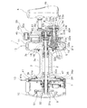
変速操作機構8は、図2及び図3に示すように、ハンドル4のハンドル軸5に回転自在に支持された高速巻き取り用の第1メインギア16及び低速巻き取り用の第2メインギア17と、第1メインギア16及び第2メインギア17にそれぞれ噛み合う状態でスプール軸2に回転自在に装着された第1ピニオンギア18及び第2ピニオンギア19と、第1メインギア16及び第2メインギア17のいずれか一方とハンドル軸5とを結合し回転を伝達する係合片20と、係合片20の図2左側に配置され係合片20及び後述する第2圧縮ばね21bを介して操作軸22を軸方向外方(図2右側)に付勢する第1圧縮ばね21aと、係合片20の図2右側に配置され係合片20を第2メインギア17側に付勢する第2圧縮ばね21bと、係合片20の位置を第1メインギア16に係合する高速位置(図2では、高速位置の係合片20を実線で示す)又は第2メインギア17に係合する低速位置の一方に設定する操作軸22とを有している。
Speed
第1ピニオンギア18は、図2に示すように、たとえば非磁性のステンレス合金等の耐蝕性を有する金属製の筒状部材である。第2ピニオンギア19は、第1ピニオンギア18と同様な材質の筒状部材である。係合片20は、ハンドル軸5のスリット内に回転不能に配置されている。操作軸22は、図2に示すように、ハンドル軸5の貫通孔5b(第2貫通孔の一例)に挿通されている。操作軸22の図2右側の端部は、ハンドルアーム4aの軸方向外方(図2右側)に突出しており、操作軸22を図2左方向に押し込むことが可能である。操作軸22は、ハンドル軸5の突出端にねじ込まれたハンドル4をハンドル軸5に固定するためのナット部材23により軸方向に移動自在に支持されている。
As shown in FIG. 2, the
変速操作機構8は、図2から図5に示すように、ハンドル4と、ナット部材23を含むハンドル軸5と、第1圧縮ばね21a、操作軸22と、ロック部材70と、ばね部材75(ロック部材付勢部材の一例)と、台座部材71と、ケース部材72とを有している。
2 to 5, the speed
ハンドル4は、図2から図5に示すように、長手方向と交差する方向に貫通孔4c(第1貫通孔の一例)が形成されたハンドルアーム4aと、ハンドルアーム4aの先端部に回転自在に装着されたハンドル把手4bとを有している。ハンドルアーム4aは、金属製の板状部材であって、基端部に形成された非円形の貫通孔4cにハンドル軸5を構成するナット部材23が一体回転可能に装着される。ハンドル軸5の基端部は、図2に示すように、貫通孔5bの内周部に雌ねじ部5aが形成されており、ナット部材23の雄ねじ部23aが螺合することによって、ハンドル軸5とナット部材23とが一体回転可能である。ナット部材23は、後述するハンドルアーム4aに固定される台座部材71の非円形孔である貫通孔71a(第3貫通孔の一例)に相対回転不能に係合する外形が6角形の頭部23bを有している。ナット部材23の中央部には貫通孔23cが形成されており、後述する操作軸22の軸部22aが移動自在に挿通される。また、ハンドルアーム4a表面の貫通孔4cの周囲の2箇所には、後述する台座部材71及びケース部材72を2つのねじ部材により固定するための2つの雌ねじ孔4fが形成されている。さらに、ハンドルアーム4a表面の貫通孔4cを挟んだ基端側及び先端側の2箇所には、後述する台座部材71の貫通孔71b(第4貫通孔の一例)及びロック部材70の貫通孔70d(第5貫通孔の一例)を挿通可能な略円柱状の第1突出部4dと、後述する台座部材71の貫通孔71d(第8貫通孔の一例)及びロック部材70の貫通孔70f(第9貫通孔の一例)を挿通可能な略円柱状の第2突出部4eとが突出して形成されている。
As shown in FIGS. 2 to 5, the
操作軸22は、図2及び図3に示すように、ハンドルアーム4aの貫通孔4cに挿通されるボルト形状の軸部材であって、軸部22aと、軸部22aより大径の押圧操作部22bとを有している。軸部22aは、図2に示すように、図2左側の先端部が第2圧縮ばね21bを介して係合片20を第2メインギア17側に押圧するように配置されている。軸部22aの基端部(図2右側)外周に被係合部22cを有している。被係合部22cは、軸部22aの外周に形成された係合溝であり、後述するロック部材70の湾曲部である係合部70cが係合可能である。軸部22aの中央部外周には、図2及び図3に示すように、環状溝22dが形成されており、環状溝22dには、操作軸22がハンドル軸5からハンドルアーム4a外方に飛び出さないようにするための2つのE型止め輪22eが装着されている。押圧操作部22bは、軸部22aの基端側(図2右側)に大径になるように形成され、釣人の押圧操作により高速と低速とに切り換えするための円形の押圧操作ボタンである。
2 and 3, the
ロック部材70は、図2から図5に示すように、台座部材71の表面に長手方向に沿うように移動自在に配置された板状の本体部70aと、本体部70aの先端に設けられた移動操作部70bとを有している。ロック部材70は、図4及び図5に示すように、操作軸22の軸部22aの被係合部22cに係合可能な係合部70cと、ハンドルアーム4aの第1突出部4dが挿通可能かつ先端側に接触して移動規制可能に長手方向に長く形成された貫通孔70dと、貫通孔70dの基端側に形成された係止部70eと、ハンドルアーム4aの第2突出部4eが挿通可能かつ基端側に接触して移動規制可能に長手方向に長く形成された貫通孔70fとをさらに有している。
As shown in FIGS. 2 to 5, the lock member 70 is provided on the surface of the
本体部70aは、図4及び図5に示すように、板状の部材である。移動操作部70bは、図4及び図5に示すように、外形が略円形になるように形成されたつまみ部であって、釣人が指で摘みやすい形状となっており、このため、移動操作部70bの移動操作が行いやすくなる。移動操作部70bは、図4に示すように、ハンドルアーム4aの長手方向に沿うように移動可能に配置される。本体部70aの先端側の側部には、被係合部22cに係合可能な係合部70cが形成されている。係合部70cは、被係合部22cに係合可能に側部が開口した略円形の貫通孔である。移動操作部70bと係合部70cとの間には、ハンドルアーム4aの第1突出部4dが挿通可能な貫通孔70dが形成されている。貫通孔70dは、第1突出部4dの先端部に接触してロック部材70を基端側に移動規制可能に長手方向に長く形成された長穴であって、ばね部材75が装着されている。貫通孔70dは、ハンドルアーム4aの第1突出部4dの外径よりやや大きい幅となるように形成されている。貫通孔70dの基端部には、先端側に突出する棒状の係止部70eが形成されており、係止部70eの周囲にばね部材75の基端側が装着される。また、本体部70aの先端部には、先端部側が開口し、ハンドルアーム4aの第2突出部4eが挿通可能な貫通孔70fが形成されている。貫通孔70fはハンドルアーム4aの第2突出部4eの基端側に接触してロック部材70を先端側に移動規制可能に長手方向に長く形成された長穴である。貫通孔70fは、ハンドルアーム4aの第2突出部4eの外径よりやや大きい幅となるように形成されている。
The main body 70a is a plate-like member as shown in FIGS. As shown in FIGS. 4 and 5, the movement operation unit 70 b is a knob part formed so that the outer shape is substantially circular, and has a shape that can be easily picked by a fisherman. It becomes easy to perform the moving operation of the unit 70b. As shown in FIG. 4, the movement operation unit 70b is arranged so as to be movable along the longitudinal direction of the
ばね部材75は、図4及び図5に示すように、ロック部材70を操作軸22方向に付勢するコイルばねであって、先端側の第1端部75aがハンドルアーム4aの第1突出部4dに接触するように配置され、基端側の第2端部75bが係止部70eに係止されるように貫通孔70dの内部に圧縮して配置されている。
4 and 5, the spring member 75 is a coil spring that biases the lock member 70 in the direction of the
台座部材71は、図2から図5に示すように、ハンドルアーム4aの表面に長手方向に沿うように配置され、プレス加工により形成された板状部材である。台座部材71は、図4及び図5に示すように、ハンドルアーム4aの貫通孔4cと連通しナット部材23の頭部23bが係合する非円形孔である貫通孔71aと、ハンドルアーム4aの第1突出部4dが挿通可能に貫通し内部にばね部材75が装着される長穴である貫通孔71bと、貫通孔71aの周囲に配置され2つのねじ部材を挿通し台座部材71をハンドルアーム4aに固定するための2つのねじ孔71cと、貫通孔71aの先端側に配置されハンドルアーム4aの第2突出部4eが挿通可能に貫通する貫通孔71dとを有している。台座部材71は、表面側にロック部材70の本体部70a及びばね部材75が移動自在に配置される台座であって、ナット部材23の頭部23bが係合する非円形孔である貫通孔71aが形成された部材であり、リテーナとしての機能を有している。貫通孔71aは、外形が6角形の頭部23bがあらゆる位置で係合するように形成された内形が多角形の貫通孔である。貫通孔71bは、ロック部材70の貫通孔70dと連通可能に長手方向に長く形成され、ばね部材75が装着される長穴である。台座部材71は、2つのねじ部材によってケース部材72とともにハンドルアーム4aの表面にねじ止めされており、2つのねじ部材は2つのねじ孔71cに挿通される。貫通孔71bは、ハンドルアーム4aの第1突出部4dが挿通し、内部にばね部材75が装着される長穴である。
As shown in FIGS. 2 to 5, the
台座部材71は、図6に示すように、貫通孔の形状が異なる2つの第1台座部材73及び第2台座部材74で構成されており、第1台座部材73及び第2台座部材74をそれぞれ別々にプレス加工したものを接着して1つの部材にしている。
As shown in FIG. 6, the
第1台座部材73は、図6に示すように、ハンドルアーム4aの貫通孔4cと連通しナット部材23の頭部23bが係合する非円形孔である貫通孔73aと、ハンドルアーム4aの第1突出部4dが挿通しかつばね部材75が装着される長穴である貫通孔73b(第6貫通孔の一例)と、2つのねじ部材を挿通し台座部材71をハンドルアーム4aに固定するための2つのねじ孔73cと、ハンドルアーム4aの第2突出部4eが挿通可能に貫通する貫通孔73dとを有している。
As shown in FIG. 6, the
第2台座部材74は、図6に示すように、ハンドルアーム4aの貫通孔4cと連通しナット部材23の頭部23bが係合する非円形孔である貫通孔74aと、ハンドルアーム4aの第1突出部4dが挿通される略円形の貫通孔である貫通孔74b(第7貫通孔の一例)と、2つのねじ部材を挿通し台座部材71をハンドルアーム4aに固定するための2つのねじ孔74cと、ハンドルアーム4aの第2突出部4eが挿通可能に貫通する貫通孔74dとを有している。ここでは、第1台座部材73と第2台座部材74とを接着したときに、第1台座部材73と第2台座部材74との外形が完全に一致している。同様に、貫通孔73aと貫通孔74aとの外形が完全に一致し、2つのねじ孔73cと2つのねじ孔74cとの外形がそれぞれ完全に一致し、貫通孔73dと貫通孔74dとの外形が完全に一致している。また、貫通孔74dは、貫通孔73bの先端部と連通するように形成されており、貫通孔74d及び貫通孔73bの先端部にハンドルアーム4aの第1突出部4dが挿通される。
As shown in FIG. 6, the
ケース部材72は、図2から図5に示すように、ハンドルアーム4aの表面に固定され、操作軸22の押圧操作部22b及びロック部材70の移動操作部70bが外部に露出するように、操作軸22、ロック部材70、ばね部材75及び台座部材71を覆うカバー部材である。ケース部材72は、図4及び図5に示すように、押圧操作部22bが外方に露出する略円形の貫通孔72bと、2つのねじ部材を挿通しケース部材72を台座部材71とともにハンドルアーム4aに固定するための2つのねじ孔72cと、移動操作部70bが側部外方に露出する矩形の側孔72dとを有している。略円形の貫通孔72bの周囲には、2つのねじ孔72cの一部にかかるように表面の一部が略円形に凹んだ凹部72aが形成されている。
As shown in FIGS. 2 to 5, the case member 72 is fixed to the surface of the
このようなロック部材70は、操作軸22の押圧操作部22bを押圧操作して操作軸22を図2左側に押し込むと、ロック部材70の係合部70cが操作軸22の被係合部22cに係合して操作軸22がロックされた状態となる。そして、ロック部材70の移動操作部70bを押す方向に移動操作すると、ロック部材70の係合部70cが操作軸22の被係合部22cから離反して操作軸22のロックが解除された状態となる。
When such a lock member 70 presses the
このような構成の変速操作機構8では、操作軸22の押圧操作部22bを押圧操作して操作軸22を図2左側に押し込むと、第2メインギア17に係合片20が配置されハンドル4の回転が第2メインギア17を介して第2ピニオンギア19に伝達されスプール3が低速回転する。一方、ロック部材70の移動操作部70bを押す方向に移動操作し、ロック部材70の湾曲部である係合部70cを操作軸22の軸部22aに形成された環状溝である被係合部22cから離反する方向にロック解除して付勢力によって操作軸22を図2右側に引き出すと、第1メインギア16に係合片20が配置されハンドル4の回転が第1メインギア16を介して第1ピニオンギア18に伝達されスプール3が高速回転する。
In the
レバードラグ機構7は、図2に示すように、スプール3の左側に装着された制動ディスク25と、制動ディスク25の左側に対向するように配置された摩擦ディスク26と、スプール3及び制動ディスク25をスプール軸2の軸方向に往復移動させるための移動機構29とを有している。
As shown in FIG. 2, the
制動ディスク25は、図2に示すように、たとえばステンレス製のワッシャ状の円板部材であり、周方向に間隔を隔てて配置された複数本の取付ピンにより、スプール3の左側のフランジ部3bの端面にスプール3と接離する方向に所定距離移動自在かつスプール3に対して回転不能に装着されている。
As shown in FIG. 2, the
摩擦ディスク26は、図2に示すように、制動ディスク25に対向して配置され、スプール軸2の軸方向に移動可能にスプール軸2に装着されている。摩擦ディスク26の制動ディスク25に対向する面には、たとえばカーボングラファイトや繊維強化樹脂等の耐摩耗性素材製のリング状の摩擦板26aがねじ止めされている。摩擦ディスク26内周部の右端面は、移動機構29のコイルばね47を介してスプール3内周部の軸受32aの内輪が当接している。摩擦ディスク26内周部の左端面は、逆転防止機構9のラチェットホイール50が当接している。ラチェットホイール50は、スプール軸2の外周面に回転不能に装着されている。ラチェットホイール50は、軸受31aの内輪に当接している。軸受31aの外輪は第1側板10に当接している。この結果、摩擦ディスク26は、スプール軸2の軸方向外方(図2左方)へ移動不能であるとともに、ラチェットホイール50により糸繰り出し方向の回転が禁止される。また、逆転防止機構9は、外周面に鋸歯が形成されたラチェットホイール50と、ラチェットホイール50の外周側に配置され先端が鋸歯を係止するラチェット爪51とを有する爪式のものである。ラチェット爪51は、第1側板10の内側面に揺動自在に装着されており、引張ばねにより鋸歯を係止する側に付勢されている。
As shown in FIG. 2, the
摩擦ディスク26の外側は、図2に示すように、ドラグカバー41により覆われている。ドラグカバー41は、たとえば放熱性能を考慮したアルミニウム合金製であり、中心に円形の開口を有する皿状のカバー本体41aと、カバー本体41aの外周面に一体形成されたリング状の取付部41bとを有している。カバー本体41aは、内部に摩擦ディスク26や制動ディスク25を収納可能な空間を有している。取付部41bは、複数本のビスなどの適宜の固定手段によりスプール3のフランジ部3bの端面に固定されており、ドラグカバー41はスプール3と一体回転するようになっている。
The outside of the
移動機構29は、図2に示すように、リール本体1に揺動自在に設けられた制動操作レバー45と、制動操作レバー45の時計回りの揺動に応じてスプール3及び制動ディスク25を押圧して図2左方に移動させる押圧機構46と、摩擦ディスク26を付勢して制動操作レバー45の反時計回りの移動に応じてスプール3及び制動ディスク25を図2右方に移動させるためのコイルばね47とを有している。コイルばね47は、摩擦ディスク26とスプール3内周部の軸受32aとの間においてスプール軸2の外周側に圧縮状態で装着され、摩擦ディスク26とスプール3とを離反する方向に付勢している。
As shown in FIG. 2, the moving
制動操作レバー45は、図2に示すように、時計回りに揺動させた制動解除位置と、反時計回りに揺動させた最大制動位置との間でリール本体1に揺動自在に装着されている。制動操作レバー45は、ボス部11aに揺動自在に装着されるレバー部45aと、レバー部45aの先端に固定されたつまみ部45bとを有している。レバー部45aの基端部は、押圧機構46を構成する第1カム部材60に回転不能に係止されている。
As shown in FIG. 2, the
押圧機構46は、ボス部11aの内周面に回転自在かつ軸方向移動不能に装着された第1カム部材60と、第1カム部材60の回動により軸方向に移動する第2カム部材61と、第2カム部材61に連動して軸方向に移動する押圧部材62とを備えている。第1カム部材60は、制動操作レバー45の揺動に連動して回動する大小2段の筒状部材である。大径の基端側の端面には傾斜カムが形成されている。第2カム部材61は、筒状の部材であり、ボス部11aの内周面に回転不能かつ軸方向移動自在に装着されている。第2カム部材61の第1カム部材60に対向する外周側の端面には、第1カム部材60の傾斜カムに係合する傾斜カムが形成されている。この2つの傾斜カムの相対回動により第1カム部材60の回動運動が第2カム部材61の軸方向の直線運動に変換され第2カム部材61が軸方向に移動する。第2カム部材61の内周面は、押圧部材62に螺合している。これにより第2カム部材61と押圧部材62との軸方向の相対位置関係を調整でき、制動操作レバー45の所定位置でのドラグ力を調整できる。
The pressing mechanism 46 includes a first cam member 60 mounted on the inner peripheral surface of the
このような両軸受リールの変速操作機構8では、台座部材71は、ハンドルアーム4aの第1突出部4dが挿通可能に貫通する貫通孔71bを有しており、ロック部材70は、ハンドルアーム4aの第1突出部4dが挿通可能かつ先端側に接触してロック部材70を移動規制可能に長手方向に長く形成された貫通孔70dを有している。ここでは、ハンドルアーム4aに第1突出部4dが形成され、ロック部材70を移動規制する貫通孔70dがロック部材70に形成されているので、従来のように台座部材71に突出部やロック部材70をガイドするガイド溝を形成する必要がなくなる。ここでは、台座部材71を板状に形成することができるので、台座部材71を単純な形状の第1台座部材73と第2台座部材74との組み合わせによって構成することができる。さらに、ここでは、従来のように台座部材71に突出部やロック部材70をガイドするガイド溝を形成する必要がなくなるので、台座部材71に凹凸がなくなることによって、台座部材71に塩が溜まりにくくなるとともに、台座部材71に塩が溜まったとしても溜まった塩を容易に分解して取り除くことができる。
In such a double-bearing reel speed
〔他の実施形態〕
(a) 前記実施形態では、中型のレバードラグリールを例にあげて説明したが、これに限られるものではなく、変速操作機構を有する両軸受リールであれば、あらゆる両軸受リールに本発明を適用できる。
[Other Embodiments]
In (a) before Symbol embodiment, the lever drag reel of medium-sized has been described as an example, not limited to this, if the dual-bearing reel having a speed change operation mechanism, the present invention in any dual-bearing reel Can be applied.
(b) 前記実施形態では、台座部材71は、2つの第1台座部材73と第2台座部材74とで構成していたが、これに限定されるものではなく、1つの部材で台座部材71を成してもよい。
(B) In the said embodiment, although the
(c) 前記実施形態では、台座部材71は、プレス加工により形成されていたが、他の製造方法により台座部材71を加工してもよい。
(C) In the said embodiment, although the
(d) 前記実施形態では、ハンドル軸5の軸方向外側に高速巻き取り用の大径の第1メインギア16が配置され、ハンドル軸5の軸方向内側に低速巻き取り用の小径の第2メインギア17が配置されており、操作軸22の押圧操作部22bの押圧操作により高速から低速に切り替えるようにしていたが、ハンドル軸5の軸方向外側に低速巻き取り用の小径の第2メインギアを配置し、ハンドル軸5の軸方向内側に高速巻き取り用の大径の第1メインギアを配置することによって、操作軸22の押圧操作部22bの押圧操作により低速から高速に切り替える構成にしてもよい。
(D) In the above-described embodiment, the first
1 リール本体
2 スプール軸
3 スプール
3a 糸巻胴部
3b フランジ部
4 ハンドル
4a ハンドルアーム
4b ハンドル把手
4c 貫通孔
4d 第1突出部
4e 第2突出部
4f 雌ねじ孔
5 ハンドル軸
5a 雌ねじ部
5b 貫通孔
6 回転伝達機構
7 レバードラグ機構
8 変速操作機構
9 逆転防止機構
10 第1側板
11 第2側板
11a ボス部
12 リールボディ
13 ハーネスラグ
14 竿取付部
16 第1メインギア
17 第2メインギア
18 第1ピニオンギア
19 第2ピニオンギア
20 係合片
21a 第1圧縮ばね
21b 第2圧縮ばね
22 操作軸
22a 軸部
22b 押圧操作部
22c 被係合部
22d 環状溝
22e E型止め輪
23 ナット部材
23a 雄ねじ部
23b 頭部
23c 貫通孔
25 制動ディスク
26 摩擦ディスク
26a 摩擦板
29 移動機構
31a 軸受
31b 軸受
32a 軸受
32b 軸受
33a 軸受
33b 軸受
41 ドラグカバー
41a カバー本体
41b 取付部
45 制動操作レバー
45a レバー部
45b つまみ部
46 押圧機構
47 コイルばね
50 ラチェットホイール
51 ラチェット爪
60 第1カム部材
61 第2カム部材
62 押圧部材
70 ロック部材
70a 本体部
70b 移動操作部
70c 係合部
70d 貫通孔
70e 係止部
70f 貫通孔
71 台座部材
71a 貫通孔
71b 貫通孔
71c ねじ孔
71d 貫通孔
72 ケース部材
72a 凹部
72b 貫通孔
72c ねじ孔
72d 側孔
73 第1台座部材
73a 貫通孔
73b 貫通孔
73c ねじ孔
73d 貫通孔
74 第2台座部材
74a 貫通孔
74b 貫通孔
74c ねじ孔
74d 貫通孔
75 ばね部材
75a 第1端部
75b 第2端部
DESCRIPTION OF SYMBOLS 1 Reel body 2 Spool shaft 3 Spool 3a Bobbin trunk 3b Flange 4 Handle 4a Handle arm 4b Handle grip 4c Through hole 4d 1st protrusion 4e 2nd protrusion 4f Female screw hole 5 Handle shaft 5a Female screw part 5b Through hole 6 Rotation Transmission mechanism 7 Lever drag mechanism 8 Shift operation mechanism 9 Reverse rotation prevention mechanism 10 First side plate 11 Second side plate 11a Boss portion 12 Reel body 13 Harness lug 14 竿 Mounting portion 16 First main gear 17 Second main gear 18 First pinion gear 19 second pinion gear 20 engagement piece 21a first compression spring 21b second compression spring 22 operation shaft 22a shaft portion 22b pressing operation portion 22c engaged portion 22d annular groove 22e E-type retaining ring 23 nut member 23a male screw portion 23b head 23c Through hole 25 Brake disc 26 Friction disc 26a Friction plate 29 Moving mechanism 31a Bearing 31b Bearing 32a Bearing 32b Bearing 33a Bearing 33b Bearing 41 Drag cover 41a Cover body 41b Mounting portion 45 Braking operation lever 45a Lever portion 45b Knob portion 46 Pressing mechanism 47 Coil spring 50 Ratchet wheel 51 Ratchet wheel 51 First cam member 61 Second cam member 62 Press member 70 Lock member 70a Main body portion 70b Movement operation portion 70c Engagement portion 70d Through hole 70e Locking portion 70f Through hole 71 Base member 71a Through hole 71b Through hole 71c Screw hole 71d Through Hole 72 Case member 72a Recess 72b Through hole 72c Screw hole 72d Side hole 73 First seat member 73a Through hole 73b Through hole 73c Screw hole 73d Through hole 74 Second seat member 74a Through hole 74b Through hole 74c Hole 74d through hole 75 a spring member 75a first end 75b second end
Priority Applications (7)
| Application Number | Priority Date | Filing Date | Title |
|---|---|---|---|
| JP2010140745A JP5686534B2 (en) | 2010-06-21 | 2010-06-21 | Double-bearing reel rotation operation mechanism |
| US13/049,258 US8534584B2 (en) | 2010-06-21 | 2011-03-16 | Dual-bearing reel speed change operation mechanism |
| SG2011021334A SG177051A1 (en) | 2010-06-21 | 2011-03-25 | Dual-bearing reel speed change operation mechanism |
| MYPI2011001423A MY157411A (en) | 2010-06-21 | 2011-03-31 | Dual-bearing reel speed change operation mechanism |
| TW100112316A TWI532429B (en) | 2010-06-21 | 2011-04-08 | Dual-bearing reel speed change operation mechanism |
| KR1020110035114A KR101746713B1 (en) | 2010-06-21 | 2011-04-15 | Dual-bearing reel speed change operation mechanism |
| CN201110167394.6A CN102283184B (en) | 2010-06-21 | 2011-06-21 | Dual-bearing reel speed change operation mechanism |
Applications Claiming Priority (1)
| Application Number | Priority Date | Filing Date | Title |
|---|---|---|---|
| JP2010140745A JP5686534B2 (en) | 2010-06-21 | 2010-06-21 | Double-bearing reel rotation operation mechanism |
Publications (3)
| Publication Number | Publication Date |
|---|---|
| JP2012000087A JP2012000087A (en) | 2012-01-05 |
| JP2012000087A5 true JP2012000087A5 (en) | 2013-07-25 |
| JP5686534B2 JP5686534B2 (en) | 2015-03-18 |
Family
ID=45327788
Family Applications (1)
| Application Number | Title | Priority Date | Filing Date |
|---|---|---|---|
| JP2010140745A Active JP5686534B2 (en) | 2010-06-21 | 2010-06-21 | Double-bearing reel rotation operation mechanism |
Country Status (7)
| Country | Link |
|---|---|
| US (1) | US8534584B2 (en) |
| JP (1) | JP5686534B2 (en) |
| KR (1) | KR101746713B1 (en) |
| CN (1) | CN102283184B (en) |
| MY (1) | MY157411A (en) |
| SG (1) | SG177051A1 (en) |
| TW (1) | TWI532429B (en) |
Families Citing this family (8)
| Publication number | Priority date | Publication date | Assignee | Title |
|---|---|---|---|---|
| US9307749B1 (en) * | 2012-05-16 | 2016-04-12 | Harout Alajajyan | Fishing reel speed control |
| ES1081005Y (en) * | 2013-05-21 | 2013-08-30 | Melian Correa Bernardo | FISHING REEL WITH TWO SPEEDS |
| JP6467218B2 (en) * | 2014-12-19 | 2019-02-06 | 株式会社シマノ | Double bearing reel |
| JP6530615B2 (en) * | 2015-02-26 | 2019-06-12 | 株式会社シマノ | Double bearing reel |
| CN107873662A (en) * | 2016-09-30 | 2018-04-06 | 宁波海宝渔具有限公司 | The two-axis winder of the fishing of variable-ratio |
| JP6784627B2 (en) * | 2017-03-27 | 2020-11-11 | グローブライド株式会社 | The handle of the fishing reel and the plate for that handle |
| US10624326B1 (en) * | 2019-05-29 | 2020-04-21 | Okuma Fishing Tackle Co., Ltd. | Gear shifting device of drum fishing reel |
| US11371796B1 (en) * | 2020-04-03 | 2022-06-28 | William J. Carpenter | Drag adjusting reel assembly |
Family Cites Families (15)
| Publication number | Priority date | Publication date | Assignee | Title |
|---|---|---|---|---|
| JPH0514780Y2 (en) * | 1987-04-11 | 1993-04-20 | ||
| JPH0822200B2 (en) * | 1989-08-25 | 1996-03-06 | 島野工業株式会社 | Reel with drag mechanism |
| JPH0739413Y2 (en) | 1989-11-06 | 1995-09-13 | 島野工業株式会社 | Double bearing reel gear shifting operation structure |
| JPH0460064U (en) * | 1990-09-25 | 1992-05-22 | ||
| US5058447A (en) * | 1990-11-30 | 1991-10-22 | Shimano Industrial Company Limited | Change-speed construction for fishing reel |
| JPH1014456A (en) * | 1996-07-04 | 1998-01-20 | Shimano Inc | Double-bearing trolling reel |
| US6360977B1 (en) * | 2000-05-26 | 2002-03-26 | Liang-Jen Chang | Change-speed construction for a fishing reel |
| US6325315B1 (en) * | 2000-06-01 | 2001-12-04 | Liang-Jen Chang | Change-speed construction for fishing reel |
| US7278599B2 (en) * | 2004-02-10 | 2007-10-09 | Harout Alajajyan | Double disc brake for brake pads of fishing reel |
| JP4334381B2 (en) * | 2004-03-25 | 2009-09-30 | 株式会社シマノ | Fishing reel, fishing information display device and fishing information display system |
| JP2006025763A (en) * | 2004-07-21 | 2006-02-02 | Shimano Inc | Handle-assembling body of fishing reel |
| US7234661B2 (en) * | 2004-07-21 | 2007-06-26 | Shimano Inc. | Drag adjustment device for a dual-bearing reel |
| JP4397043B2 (en) * | 2005-03-22 | 2010-01-13 | グローブライド株式会社 | Fishing reel |
| JP5047889B2 (en) * | 2008-06-19 | 2012-10-10 | グローブライド株式会社 | Fishing reel |
| JP5474428B2 (en) * | 2009-07-14 | 2014-04-16 | 株式会社シマノ | Double-bearing reel speed change mechanism |
-
2010
- 2010-06-21 JP JP2010140745A patent/JP5686534B2/en active Active
-
2011
- 2011-03-16 US US13/049,258 patent/US8534584B2/en active Active
- 2011-03-25 SG SG2011021334A patent/SG177051A1/en unknown
- 2011-03-31 MY MYPI2011001423A patent/MY157411A/en unknown
- 2011-04-08 TW TW100112316A patent/TWI532429B/en active
- 2011-04-15 KR KR1020110035114A patent/KR101746713B1/en active IP Right Grant
- 2011-06-21 CN CN201110167394.6A patent/CN102283184B/en active Active
Similar Documents
| Publication | Publication Date | Title |
|---|---|---|
| JP2012000087A5 (en) | ||
| JP2012000087A (en) | Dual-bearing reel speed change operation mechanism | |
| JP5324819B2 (en) | Lever drag reel reverse rotation prevention mechanism | |
| US9295243B2 (en) | Ratchet wheel for fishing reel | |
| JP2009273378A5 (en) | ||
| JP5746841B2 (en) | Clutch control device for double bearing reel | |
| JP5474428B2 (en) | Double-bearing reel speed change mechanism | |
| JP2012065574A5 (en) | ||
| JP2014176359A5 (en) | ||
| JP5242353B2 (en) | Drag adjusting device for double-bearing reel | |
| JP2011019428A (en) | Dual-bearing reel lever drag mechanism | |
| JP2011019428A5 (en) | ||
| KR20040018985A (en) | Reciprocating Device for Spinning Reel | |
| JP2006025763A (en) | Handle-assembling body of fishing reel | |
| JP6247115B2 (en) | Spinning reel | |
| JP2015159757A5 (en) | ||
| JP5460250B2 (en) | Spinning reel rotor braking device | |
| JP5986876B2 (en) | Fishing reel handle device | |
| JP6489885B2 (en) | Spinning reel | |
| KR20110019701A (en) | Brake device for spinning reel rotor | |
| JP2006166715A (en) | Handle grip of reel for fishing and handle assembly of reel for fishing | |
| JP6748598B2 (en) | Dual bearing reel with sounding mechanism | |
| JP2016174543A5 (en) | ||
| JP2003235412A (en) | Handle assembly of fishing reel | |
| JP2018174763A (en) | Double-bearing type reel with sound producing mechanism |