JP5679042B2 - Guide pad, cutting tool body and cutting tool - Google Patents
Guide pad, cutting tool body and cutting tool Download PDFInfo
- Publication number
- JP5679042B2 JP5679042B2 JP2013502221A JP2013502221A JP5679042B2 JP 5679042 B2 JP5679042 B2 JP 5679042B2 JP 2013502221 A JP2013502221 A JP 2013502221A JP 2013502221 A JP2013502221 A JP 2013502221A JP 5679042 B2 JP5679042 B2 JP 5679042B2
- Authority
- JP
- Japan
- Prior art keywords
- guide pad
- guide
- cutting tool
- longitudinal direction
- axis
- Prior art date
- Legal status (The legal status is an assumption and is not a legal conclusion. Google has not performed a legal analysis and makes no representation as to the accuracy of the status listed.)
- Active
Links
- 238000005520 cutting process Methods 0.000 title claims description 75
- 239000000463 material Substances 0.000 claims description 15
- 238000005553 drilling Methods 0.000 claims description 7
- 230000001154 acute effect Effects 0.000 claims description 5
- 239000011195 cermet Substances 0.000 claims description 2
- 239000000919 ceramic Substances 0.000 claims 1
- 238000003754 machining Methods 0.000 description 18
- 229910000831 Steel Inorganic materials 0.000 description 8
- 239000010959 steel Substances 0.000 description 8
- 238000004519 manufacturing process Methods 0.000 description 4
- 230000002093 peripheral effect Effects 0.000 description 4
- 230000015572 biosynthetic process Effects 0.000 description 3
- 238000005219 brazing Methods 0.000 description 3
- 230000000694 effects Effects 0.000 description 3
- 238000000034 method Methods 0.000 description 3
- 238000012545 processing Methods 0.000 description 3
- 230000002159 abnormal effect Effects 0.000 description 2
- 238000007796 conventional method Methods 0.000 description 2
- 238000013461 design Methods 0.000 description 2
- 238000009434 installation Methods 0.000 description 2
- 102200082816 rs34868397 Human genes 0.000 description 2
- 229910000975 Carbon steel Inorganic materials 0.000 description 1
- 239000010962 carbon steel Substances 0.000 description 1
- 229910010293 ceramic material Inorganic materials 0.000 description 1
- 239000011248 coating agent Substances 0.000 description 1
- 238000000576 coating method Methods 0.000 description 1
- 230000007423 decrease Effects 0.000 description 1
- 230000003247 decreasing effect Effects 0.000 description 1
- 238000010586 diagram Methods 0.000 description 1
- 239000006185 dispersion Substances 0.000 description 1
- 238000002474 experimental method Methods 0.000 description 1
- 238000000227 grinding Methods 0.000 description 1
- 239000000843 powder Substances 0.000 description 1
- 238000003825 pressing Methods 0.000 description 1
- 238000006748 scratching Methods 0.000 description 1
- 230000002393 scratching effect Effects 0.000 description 1
- 238000005245 sintering Methods 0.000 description 1
- 239000000126 substance Substances 0.000 description 1
- 238000004381 surface treatment Methods 0.000 description 1
- 230000008646 thermal stress Effects 0.000 description 1
Images


Classifications
-
- B—PERFORMING OPERATIONS; TRANSPORTING
- B23—MACHINE TOOLS; METAL-WORKING NOT OTHERWISE PROVIDED FOR
- B23B—TURNING; BORING
- B23B51/00—Tools for drilling machines
-
- B—PERFORMING OPERATIONS; TRANSPORTING
- B23—MACHINE TOOLS; METAL-WORKING NOT OTHERWISE PROVIDED FOR
- B23B—TURNING; BORING
- B23B51/00—Tools for drilling machines
- B23B51/0054—Drill guiding devices
-
- B—PERFORMING OPERATIONS; TRANSPORTING
- B23—MACHINE TOOLS; METAL-WORKING NOT OTHERWISE PROVIDED FOR
- B23B—TURNING; BORING
- B23B2200/00—Details of cutting inserts
-
- B—PERFORMING OPERATIONS; TRANSPORTING
- B23—MACHINE TOOLS; METAL-WORKING NOT OTHERWISE PROVIDED FOR
- B23B—TURNING; BORING
- B23B2200/00—Details of cutting inserts
- B23B2200/04—Overall shape
-
- B—PERFORMING OPERATIONS; TRANSPORTING
- B23—MACHINE TOOLS; METAL-WORKING NOT OTHERWISE PROVIDED FOR
- B23B—TURNING; BORING
- B23B2200/00—Details of cutting inserts
- B23B2200/04—Overall shape
- B23B2200/0447—Parallelogram
-
- B—PERFORMING OPERATIONS; TRANSPORTING
- B23—MACHINE TOOLS; METAL-WORKING NOT OTHERWISE PROVIDED FOR
- B23B—TURNING; BORING
- B23B2251/00—Details of tools for drilling machines
- B23B2251/56—Guiding pads
-
- Y—GENERAL TAGGING OF NEW TECHNOLOGICAL DEVELOPMENTS; GENERAL TAGGING OF CROSS-SECTIONAL TECHNOLOGIES SPANNING OVER SEVERAL SECTIONS OF THE IPC; TECHNICAL SUBJECTS COVERED BY FORMER USPC CROSS-REFERENCE ART COLLECTIONS [XRACs] AND DIGESTS
- Y10—TECHNICAL SUBJECTS COVERED BY FORMER USPC
- Y10T—TECHNICAL SUBJECTS COVERED BY FORMER US CLASSIFICATION
- Y10T407/00—Cutters, for shaping
- Y10T407/23—Cutters, for shaping including tool having plural alternatively usable cutting edges
-
- Y—GENERAL TAGGING OF NEW TECHNOLOGICAL DEVELOPMENTS; GENERAL TAGGING OF CROSS-SECTIONAL TECHNOLOGIES SPANNING OVER SEVERAL SECTIONS OF THE IPC; TECHNICAL SUBJECTS COVERED BY FORMER USPC CROSS-REFERENCE ART COLLECTIONS [XRACs] AND DIGESTS
- Y10—TECHNICAL SUBJECTS COVERED BY FORMER USPC
- Y10T—TECHNICAL SUBJECTS COVERED BY FORMER US CLASSIFICATION
- Y10T408/00—Cutting by use of rotating axially moving tool
- Y10T408/55—Cutting by use of rotating axially moving tool with work-engaging structure other than Tool or tool-support
- Y10T408/557—Frictionally engaging sides of opening in work
- Y10T408/558—Opening coaxial with Tool
- Y10T408/5583—Engaging sides of opening being enlarged by Tool
- Y10T408/5586—Engaging surface subsequent to tool-action on that surface
-
- Y—GENERAL TAGGING OF NEW TECHNOLOGICAL DEVELOPMENTS; GENERAL TAGGING OF CROSS-SECTIONAL TECHNOLOGIES SPANNING OVER SEVERAL SECTIONS OF THE IPC; TECHNICAL SUBJECTS COVERED BY FORMER USPC CROSS-REFERENCE ART COLLECTIONS [XRACs] AND DIGESTS
- Y10—TECHNICAL SUBJECTS COVERED BY FORMER USPC
- Y10T—TECHNICAL SUBJECTS COVERED BY FORMER US CLASSIFICATION
- Y10T408/00—Cutting by use of rotating axially moving tool
- Y10T408/96—Miscellaneous
- Y10T408/98—Drill guide
Description
本発明は、切削工具を支持するために切削工具へ着脱自在に装着されるガイドパッド、このガイドパッドを装着する切削工具本体、および、このガイドパッドが装着される切削工具に関する。 The present invention relates to a guide pad that is detachably attached to a cutting tool to support the cutting tool, a cutting tool main body to which the guide pad is attached, and a cutting tool to which the guide pad is attached.
従来のガイドパッドとして、特許文献1に示すものがある。特許文献1のガイドパッドは、主として深孔切削に使用されるドリルヘッドの先端外周に取り付けられ、ドリルが加工した加工穴に当接することでドリル自らを支持する。このようなガイドパッドはドリルへ着脱自在に装着される。このガイドパッドは、略長方形状の外形の板状をなし、長手方向の中央に形成された1つの取付穴と、この取付穴の長手方向の両側に形成され、ガイド面として加工穴に当接する略円弧状の断面形状をもつ2つの曲面とを有する。このガイドパッドは、超硬合金で形成されたガイド面部分と、このガイド面部分がろう付けされる、工具本体への取付穴を有する鋼材部分とから構成される。すなわち、このガイドパッドは、鋼材およびろう材を有する。このガイドパッドは、超硬合金と鋼材とのろう付けのときに、熱応力の差から超硬合金にクラックが発生するのを抑制するために、鋼材の取り付け台座部分の横断面が略L字状に形成される。
A conventional guide pad is disclosed in
また、従来のガイドパッドとして、特許文献2に示すものがある。特許文献2のガイドパッドは、実質的に長方形状の外形を有する板状に形成され、その2つの長辺からそれぞれ延出する翼形状突起を有する。このガイドパッドは、その全体を超硬合金材料で形成するため、取付穴周辺の強度を確保するために、取付穴から外周側面までの壁厚が薄くならないように、翼形状突起が設けられている。
Moreover, there exists a thing shown in
例えば、1枚刃の穴あけ加工用の切削工具において、一般的には、ガイドパッドは工具の先端側からみて、切れ刃に対して回転軸線回りに180°の位置と、切れ刃に対して工具の相対回転方向の後方の90°の位置の、2箇所に設けられることが好ましい。すなわち、ガイドパッドは切れ刃から最も離れた位置と、切削抵抗の3分力の中で最も大きい主分力を受ける位置とに設けられることが好ましい。しかしながら、加工穴径を規定する工具径が比較的小さいときは、ガイドパッドをこのような好ましい位置に設けることが困難な場合がある。 For example, in a cutting tool for drilling with a single blade, generally, the guide pad is located at a position of 180 ° around the rotation axis with respect to the cutting edge as viewed from the tip side of the tool, and the tool with respect to the cutting edge. It is preferable to be provided at two positions at 90 ° rearward in the relative rotation direction. That is, it is preferable that the guide pad is provided at a position farthest from the cutting edge and a position that receives the largest main component force among the three component forces of the cutting resistance. However, when the tool diameter that defines the machining hole diameter is relatively small, it may be difficult to provide the guide pad at such a preferred position.
この主な原因は、切削インサートまたは切削インサートの締結機構部品と、ガイドパッドとの干渉である。したがって、ガイドパッドは、占有面積が可能な限り小さいことが好ましい。しかしながら、締め付けねじなどによるガイドパッドの締結のためには、取付穴の周辺は、十分な強度が必要である。特許文献1のガイドパッドは、取り付け台座部分の横断面が略L字状に形成されるために、ガイドパッドの幅が、鋼材の略L字状に形成された壁の分だけ、幅広に形成される。つまり、特許文献1のガイドパッドは、ガイド面が取り付け台座部分とは別部材で形成されるため、ガイドパッドの寸法を小さくしたり、幅を狭くしたりするのに適した構造ではない。特許文献2のガイドパッドは、その全体を超硬合金で形成するため、寸法を小さくしたり、幅を狭くしたりするのには適した構造である。しかしながら、ガイドパッドの2つの長辺から左右対称に突出させる翼形突起が他の部品と干渉しやすい。
The main cause is interference between the cutting insert or the fastening mechanism part of the cutting insert and the guide pad. Therefore, it is preferable that the guide pad occupies as small an area as possible. However, in order to fasten the guide pad with a fastening screw or the like, a sufficient strength is required around the mounting hole. The guide pad of
本発明は、配置の自由度が向上したガイドパッド、このガイドパッドを装着する切削工具本体、および、このガイドパッドが装着される切削工具を提供する。 The present invention provides a guide pad with an improved degree of freedom in arrangement, a cutting tool body on which the guide pad is mounted, and a cutting tool on which the guide pad is mounted.
本発明のガイドパッドは、対向する上面(2)及び下面(3)と、該上面(2)と該下面(3)との間で延びる側面(6)と、を有し、切削工具の工具本体(10)へ着脱自在に装着される板状のガイドパッド(1)であって、前記上面(2)は、前記ガイドパッド(1)の長手方向(A)に延び、かつ、凸状に湾曲する少なくとも一のガイド面(2a)を有し、前記上面(2)および下面(3)は、左右非対称な外形をそれぞれ有する、ことを特徴とする。 The guide pad of the present invention has an upper surface (2) and a lower surface (3) facing each other, and a side surface (6) extending between the upper surface (2) and the lower surface (3). A plate-shaped guide pad (1) detachably attached to a main body (10), wherein the upper surface (2) extends in the longitudinal direction (A) of the guide pad (1) and is convex. It has at least one guide surface (2a) that is curved, and the upper surface (2) and the lower surface (3) each have a laterally asymmetric outer shape.
本発明の切削工具は、上記のガイドパッド(1)と、前記ガイドパッド(1)が着脱自在に装着される工具本体(10)と、を有することを特徴とする。 The cutting tool of this invention has said guide pad (1) and the tool main body (10) to which the said guide pad (1) is detachably mounted | worn, It is characterized by the above-mentioned.
本発明の切削工具本体は、上記のガイドパッド(1)を受容可能なパッド座を備えることを特徴とする。 The cutting tool main body of the present invention includes a pad seat that can receive the guide pad (1).
本発明のガイドパッドは、上面および下面の外形が左右非対称、すなわち、いずれの方向においても対称軸線を有さないように形成される。このため、ガイドパッドは、工具本体に対する配置にあわせて干渉の生じない形状に形成できる。この結果、ガイドパッドの配置の自由度が高まる。 The guide pad of the present invention is formed so that the outer shape of the upper surface and the lower surface is asymmetrical, that is, does not have a symmetric axis in any direction. For this reason, a guide pad can be formed in the shape which does not produce interference according to arrangement | positioning with respect to a tool main body. As a result, the degree of freedom of arrangement of the guide pad is increased.
本発明の実施形態について、図面を参照しながら説明する。 Embodiments of the present invention will be described with reference to the drawings.
第1実施形態
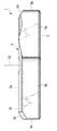
図1から図4に示すように、本実施形態にかかるガイドパッド1は、対向する上面2及び下面3と、該上面2と該下面3との間で延びる複数の側面6a,6b,6cとを有し、平板状に形成されている。複数の側面6a,6b,6cの総称を側面6とする。上面2及び下面3の外形は、略平行四辺形形状である。ただし、上面2及び下面3の外形は、鋭角のコーナ部分の頂部が切頭されているため、略六角形状にもみえる。複数の側面6a,6b,6cのうち、長手方向Aに沿って延びる対向する2つの側面6a,6aは、実質的に平面で形成され、略平行に配置されている。2つの側面6b,6bも、実質的に平面で形成され、略平行に配置されている。2つの側面6c,6cも、実質的に平面で形成され、略平行に配置されている。下面3は、実質的に平面で構成される。上面2の構成については後述する。 First Embodiment As shown in FIGS. 1 to 4, a
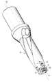
ガイドパッド1は、例えば、図5および図6に示すように、刃先交換式ドリルである回転切削工具の工具本体10に、着脱自在に装着される。上面2には、ガイド面2aが形成されている。ガイド面2aは、略円弧状の断面形状をもつ曲率半径Rの曲面で形成され、長手方向Aに延びている。ガイド面2aは、その一部がドリルによって加工される加工穴の内壁面に接触し、ドリルを支持するように作用する。この作用により、ドリルは加工穴に案内され、ドリルの直進性が高まる。ガイド面2aの両端部2bのうち、ドリルの先端側に位置する端部2b付近が、加工穴の内壁面と接触するように配置される。すなわち、ガイドパッド1は、ガイド面2aの一方の端部2b以外の部分が逃げるように、わずかに傾けて配置される。なお、ガイドパッド1が切削工具へ着脱自在に装着されるとは、容易に交換できることを意味する。例えば、ガイドパッド1が締め付けねじ11などによって固定される場合である。ガイドパッド1の装着方法は、締め付けねじ11に限定されない。公知のさまざまな装着方法を採用できる。
For example, as shown in FIGS. 5 and 6, the
ガイド面2aの具体的な形状は、ガイド面2aの曲率半径Rがガイド穴の直径φDの半分よりも小さいことである。ここで、ガイド穴とは前述の加工穴のように、ガイドパッドを案内する穴のことである。例えば、ガイドパッド1が刃先交換式ドリルに用いられて、ガイド穴径と加工穴径とが略等しく、かつ、当該ドリルにより加工される加工穴に案内される場合には、好ましくは、略円弧状の断面形状をもつガイド面2aを構成する略円弧の曲率半径は、ガイドパッド1によって加工される加工穴の直径φDの半分(半径)よりも小さい値に設定される。ガイド面2aの曲率半径Rと、加工穴の直径φDとの関係を、模式的に図7に示す。つまり、曲率半径Rと直径φDとの関係は、R<(φD/2)の関係とする。
The specific shape of the
曲率半径Rが加工穴の穴径φDの半分より大きいと、ガイド面2aがガイド穴となる加工穴に接触せず、ガイド機能を果たせず、加工穴に対して一方のエッジが接触することになる。ガイド面2aのエッジが加工穴の内壁面に接触すると、加工穴の内壁面が損傷する可能性がある。
If the radius of curvature R is larger than half of the hole diameter φD of the processed hole, the
本実施形態のガイド面2aは、一定の曲率半径Rを有する。例えば、加工穴径φDが直径約32mmの刃先交換式ドリルに装着されるガイドパッド1の場合、ガイド面2aの曲率半径Rは、約15.0mmに設定することができる。本実施形態では、ガイド面2aの曲率半径Rを一定としているため、ガイド面2aの曲率中心は、図4に示すように、軸線C1上にある。軸線C1は、図4の紙面に垂直な方向に延び、かつ、下面3に平行な直線である。なお、本実施形態では、曲率半径Rが一定の場合について説明するが、本発明はこれに限定されず、例えば、ガイド面2aの曲率半径Rが長手方向Aにおいて変化する場合や円弧の曲率が当該円弧上の位置に応じて変化する場合にも適用される。
The
ガイドパッド1には、図2に示すように、上面2及び下面3を貫通する単一の取付穴8が形成され、ガイドパッド1は、取付穴8の中心軸線C2に関して180度回転対称に形成されている。中心軸線C2は、軸線C1と交差している。また、軸線C1を含み2つの側面6a,6aの間の中央を通る平面を基準平面Sとすると、基準平面Sはガイドパッド1を実質的に2等分する。ガイドパッド1の上面2および下面3の外形は、図2から分かるように、基準平面Sに関して、非対称な形状に形成されている。すなわち、上面2および下面3は、左右非対称な外形を有し、いずれの方向においても対称軸線を持たない。さらに、ガイドパッド1の長手方向Aの両端部における幅L1は、中心軸線C2の位置での幅、すなわち、2つの側面6a,6a間の幅L2よりも小さくなっている。ガイドパッド1は、取付穴8の形成領域付近で最大の幅L2を有し、長手方向Aの両端部に向かってその幅が徐々に狭くなり、長手方向Aの両端部において最小の幅L2を有する。また、長手方向Aの各端部は、基準平面Sから、各側面6a側にオフセットしている。
As shown in FIG. 2, the
本実施形態では、ガイドパッド1の各端部の幅L1は、約2.00mmに設定される。幅L2は、約6.35mmに設定される。なお、幅L2は約5.56mmなどと、より小さな幅L2にすることもでき、切削工具の工具本体10に着脱自在に装着できる大きさであれば、特に限定されない。また、本実施形態では、ガイドパッド1の略平行四辺形形状の外形の鋭角コーナの角度は、約35.0°であるが、これに限定されるわけではない。ガイドパッド1の鋭角コーナの角度は、これが装着される切削工具の他の構成部品と干渉せず、なおかつ、強度を保ちながら全体の寸法が小さくなるように、適切に調整されればよく、例えば、鋭角コーナの角度を、約55.0°としてもよい。
In the present embodiment, the width L1 of each end portion of the
本実施形態では、切削インサート12を工具本体10に装着する締結部品として、切削インサートの締め付けねじ13が用いられる。ガイドパッド1の形状は、切削インサート12の締め付けねじ13や、その雌ねじ側の下穴との干渉なども考慮して調整される。また、切削インサート12の締結部品は、締め付けねじ13に限定されない。さまざまな従来技術が適用可能である。どのような締結方法が採用されたときにも、すべての部品との干渉を回避するように、ガイドパッド1が配置されればよい。
In this embodiment, a
ガイドパッド1の厚さは、締め付けねじ11の頭部がガイド面2aより突出せず、なおかつ、締め付けるためのガイドパッド1の強度が高められるように、適切に調整される。本実施形態のガイドパッド1の最も厚い部分の厚さは、約3mmである。また、ガイドパッド1の上面2の長手方向Aの両端部は、面取り2cが形成される。面取り2cは、ガイドパッド1が加工穴の内壁面に傷をつけることを防止するとともに、ガイドパッド1がチッピングなどの異常損傷を生じることを防止する。なお、ガイド面2aは、面取り2cの近傍から取付穴2側に向かって、加工穴の内壁面とガイド面2aとの間にクリアランスが確保されるように配置されて、面取り2cの近傍の端部2bがガイド機能を発揮する。
The thickness of the
本実施形態のガイドパッド1は、図1,2および4からわかるように、2つのガイド面2aが基準面Sの両側に別々に形成されている。
As can be seen from FIGS. 1, 2, and 4, the
このように、2つのガイド面2aがあると、例えば、使用によってガイド面2aの一方が損傷した場合に、損傷していない他方のガイド面2aを使用することができる。言い換えれば、一方のガイド面2aが損傷した場合であっても、2つのガイド面2aは別々に形成されているため、他方のガイド面2aが一方のガイド面2aと同時に損傷するのを防ぐことができる。
Thus, when there are two
本実施形態のガイドパッド1は、図7に示すように、ガイドパッド1が着脱自在に装着されるとき、少なくとも取付穴2の中心軸線C2が、切削工具の回転軸線C3と交差しないように回転軸線C3に対してオフセットしている。すなわち、中心軸線C2が、加工穴の中心軸線と交差しないように、ガイドパッド1が傾けて配置される。このように配置されると、2つのガイド面2aのうち、一方のガイド面2aが加工穴の内壁面に確実に接触し、他方のガイド面2aと加工穴の内壁面との間に十分なすきまが確保される。このため、他方のガイド面2aの損傷をより確実に防止することができる。
As shown in FIG. 7, the
ガイドパッド1の側面6aおよび6bの一部、および下面3の一部は、工具本体10へ装着されるときの着座面として機能する。2つのガイド面2aの間には、図4からわかるように、凹状の溝2dが形成されるが、本実施形態の溝2dは比較的単純な形状であるが、これに限定されない。2つのガイド面2aを十分に分離できる限り、いずれの形状の溝も採用できる。なお、本実施形態では、2つのガイド面2aは、共通の曲率中心をもつ曲面で形成されるが、これに限定されない。2つのガイド面2aは、異なる曲率中心をもっていてもよいし、異なる曲率半径を持っていてもよい。前述のとおり、ガイド面2aの曲率半径Rは、加工穴の直径φDの半分よりも小さければよく、それぞれ異なる形状や、変化する形状などの任意の形状とされても構わない。
Part of the side surfaces 6 a and 6 b of the
本発明のガイドパッド1は、その全体が超硬合金、サーメット又はセラミックの材料で形成され、あるいは、これら硬質物質の表面に硬質皮膜がコーティングされていてもよい。すなわち、本発明のガイドパッド1の形成材料として、鋼材やろう材を用いる必要がない。このため、ガイドパッド1の寸法を小さくすることができ、工具本体10への配置の自由度が高まる。
The
前述のとおり、本実施形態では、ガイド面2aの曲率半径Rを一定としたが、これに限定されない。積極的に曲率半径Rを変化させて、取付穴2に近づくにしたがい曲率半径Rを小さくするなど、ガイドパッド1と加工穴の内壁面との間のすきまなどが適切に調整されてもよい。また、複数の側面6a、6b、6cの接続部分には、丸みがつけられる。これは、ガイドパッド1が、チッピングなどの異常損傷を生じることを防止するためである。この実施形態では、これらのコーナの曲率半径は、6ヶ所すべて、約R0.4mmとされる。
As described above, in this embodiment, the radius of curvature R of the
本実施形態では、ガイドパッド1は上記したように、取付穴2の中心軸線C2に関して180度回転対称な形状に形成される。これにより、2つのガイド面2aのうち、一方のガイド面2aを使用したのち、ガイドパッド1を中心軸線C2回りに180度回転させることで、他方のガイド面2aを使用できる。なお、工具本体10への装着およびガイド面2aによるガイド機能に影響がない部分については、必ずしも、取付穴2の中心軸線C2に関して対称な形状としなくてもよい。支持(ガイド)機能に影響しない範囲で、適宜デザインの変更が可能である。
In the present embodiment, the
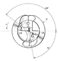
図5のドリルにおいて、ガイドパッド1は、図8に示す位置に配置される。このドリルは、外周刃用の切削インサート12Aと中心刃用の切削インサート12Bとがそれぞれ1つずつ装着される。ガイドパッド1は、図8に示すように、切削インサート12Aの切れ刃から工具の相対回転方向Rの前方の約145°の位置と、切削インサート12Aの切れ刃から工具の相対回転方向Rの後方の約79°の位置との2箇所に装着される。上述のとおり、1枚刃のドリルの場合、ガイドパッドの最適な位置は、外周切れ刃から工具の相対回転方向の180°の位置と、外周切れ刃から工具の相対回転方向の後方に90°の位置の2箇所である。本実施形態では、最適な位置からのずれ量は、それぞれ、約35°および約11°にすることができる。なお、同種の工具で、従来のガイドパッドが配置される場合には、ずれ量がそれぞれ、48°程度および20°程度が限界であった。本発明のガイドパッド1によれば、従来と比べて、ずれ量をそれぞれ約13°および9°改善できる。この効果として、鋼材S45Cに穴をあける実験の結果、加工される穴の直径精度が約30%改善された。
In the drill of FIG. 5, the
具体的には、ドリル径:50.0mm、全長370mmのドリルを立形マシニングセンタに装着し、被削材として炭素鋼S45C(220HB)を使用した。切削条件は、切削速度Vc=150m/min、送りf=0.10mm/rev、加工穴の深さ150mmとし、ドリルの内部を通じて給油した。そして、本実施形態のガイドパッド1を装着したドリル、従来のガイドパッドを装着したドリルおよびガイドパッドを装着しないドリルを用いて、12個の穴をそれぞれ被削材に加工し、加工穴の直径のばらつきを評価した。加工穴の直径のばらつきは、本実施形態のガイドパッド1を装着したドリルでは、加工穴の入口付近と深部との差で約0.12mmとなった。一方、ガイドパッドなしのドリルでは、約0.24mm、従来のガイドパッドを装着したドリルでは、約0.17mmであり、本実施形態は、従来のガイドパッドを装着したドリルに対して加工穴の精度が最大で約30%改善した。
Specifically, a drill having a drill diameter of 50.0 mm and a total length of 370 mm was mounted on a vertical machining center, and carbon steel S45C (220HB) was used as a work material. Cutting conditions were a cutting speed Vc = 150 m / min, a feed f = 0.10 mm / rev, and a depth of a processed hole of 150 mm, and oil was supplied through the inside of the drill. Then, using the drill with the
第2実施形態
次に、第2の実施形態にかかるガイドパッド1Aを、図9に示す。この実施形態のガイドパッド1は、上面2に単一のガイド面2aが形成される。このように、ガイド面2aが単一であっても、ガイド面2aの長手方向Aの両端部2b,2bにガイド機能を持たせることができる。したがって、ガイドパッド1Aも、取付穴8を中心に180度回転させれば、ガイド面2aの2つの端部2b、2bを別々に使用できる。第2の実施形態にかかるガイドパッド1Aを使用するときも、ガイドパッド1Aは、その取付穴2の中心軸線C2が、切削工具の回転軸線C3に対してオフセットするように配置されるとよい。そのように配置されると、ガイド面2aの一方の端部2bが使用されるときに、他方の端部2bと加工穴の内壁面との間に、すきまが十分に確保される。このため、他方の端部2bの損傷が防止される。Second Embodiment Next, a
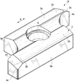
第3実施形態
第3の実施形態にかかるガイドパッド1Bを、図10および図11に示す。ガイドパッド1Bの上面2および下面3の外形は、略平行四辺形形状ではない。ガイドパッド1Bは、ガイド面2aの面取り2c側の端部2bの幅が取付穴8付近の幅よりも狭く形成され、基準平面Sに関して非対称に形成されている。本実施形態では、ガイドパッド1の幅は、取付穴2の形成付近の最大の幅L2と、両端部2bにおける最小の幅L1との間で、任意に変化するように調整される。図示しないが、幅L2よりも広い幅まで一旦拡張されてから、幅L2まで再び戻されるようなデザインでも構わない。切削工具の他の構成部品と干渉しない範囲であれば、自由に調整できる。 Third Embodiment FIG. 10 and FIG. 11 show a
本実施形態では、使用できる回数が2回に設定されたため、ガイド面2aは2つにされるが、これに限定されない。例えば、使用できる回数が3回以上に設定された場合は、それに応じてガイド面2aを3つ以上設けることができる。
In the present embodiment, since the number of times of use is set to two, the number of
本実施形形態では、対向する2つの側面6b,6bが平行な場合について説明したが、これに限定されるわけではなく、2つの側面は非平行であってもよく、また、互いに異なる形状の曲面であってもよい。つまり本実施形態では、複数の側面は平面としたが、これに限定されない。切削工具の他の構成部品との干渉を防止するために、さらに複雑な曲面で構成してもよい。例えば、複数の曲面を滑らかにつないだような、単一の環状曲面などで側面を形成できる。また、本実施形態では、ガイドパッド1の幅は、取付穴8の形成領域で相対的に広く、両端部において相対的に狭くなっている場合について説明したが、これに限定されるわけではない。ガイドパッド1のガイド面部分付近の幅は、取り付け穴付近の幅より狭くすればよく、長手方向における幅の変化の程度は任意でよい。
In the present embodiment, the case where the two opposing
本発明のガイドパッドの製造方法は、従来のガイドパッドの製造方法をそのまま利用できる。例えば、粉末加圧成形および焼結による従来技術の製造工程にて製造される。必要に応じて、ガイド面2aや面取り2cなどの研削加工が追加される。さらに必要に応じて、CVDやPVDによる硬質被膜のコーティングなどの表面処理が施される。すべての製造工程において、様々な従来技術が適用可能である。
The conventional guide pad manufacturing method can be used as it is for the guide pad manufacturing method of the present invention. For example, it is manufactured by a conventional manufacturing process using powder pressing and sintering. If necessary, grinding processing such as
本発明のガイドパッドを着脱自在に装着できる切削工具としては、刃先交換式ドリルが代表的である。他にも、ガンドリルやリーマなど,特に穴あけ加工用、中でも深穴加工用の切削工具に装着されると効果的である。しかし、これに限定されない。ガイドパッドを使用するすべての切削工具に適用できる。 As a cutting tool to which the guide pad of the present invention can be detachably mounted, a blade-tip replaceable drill is representative. In addition, it is effective when mounted on a cutting tool for drilling, especially deep drilling, such as a gun drill or reamer. However, it is not limited to this. Applicable to all cutting tools that use guide pads.
前述のとおり、本発明のガイドパッド1を着脱自在に装着できる切削工具が回転切削工具の場合は、取付穴8の中心軸線C2が、切削工具の回転軸線C3と交差しないように配置されるとよい。このような配置になるように、工具本体10におけるガイドパッドの設置個所を設定する。このようにすると、ガイド面2aの2つ以上の端部2bが、1つずつ確実に作用するため、他の端部の損傷が防止される。
As described above, when the cutting tool to which the
本発明のガイドパッドが着脱自在に装着された切削工具は、例えばマシニングセンタや旋盤などの工作機械へ着脱自在に装着され、工具回転軸を中心とする相対回転運動を与えられ、また被削材をとの間に相対運動を与えられ、鋼材などの被削材の切削加工を行う。切削工具がドリルの場合などは、切削工具自らによってあけられた穴の内面にガイドパッドが接触し、支持(ガイド)されることによって、加工される穴の加工精度が向上する。本発明のガイドパッドおよび切削工具は、ボール盤などの工作機械でも使用可能である。本発明のガイドパッドは、主に1枚刃の回転切削工具に装着されるとき、その効果が発揮される。一方で、2枚刃や4枚刃の穴あけ加工用の切削工具などは、1つの切れ刃から工具の相対回転方向に約180°の位置に、別の切れ刃がある。このような場合には、ガイドパッドを設けるのに好ましい位置が異なる。例えば、2枚刃の場合は、各切れ刃から約90°の位置にガイドパッドを配置することが好ましい。4枚刃の場合は、各切れ刃から約45°の位置にガイドパッドを配置することが好ましい。ただし、4つの切れ刃(切削インサート)と4つのガイドパッド1を設置することが困難な場合、例えば、4つの切れ刃の中に他の切れ刃よりも切り込みの大きいあら刃を設けて、そのあら刃を基準にして、工具の相対回転方向の180°の位置と、あら刃から工具の相対回転方向の後方の90°の位置との2箇所にガイドパッドを配置する。本発明のガイドパッドは、設置するときの制約が少ないため、2枚刃以上の穴あけ加工用の切削工具などに適用することもできる。
The cutting tool to which the guide pad of the present invention is detachably attached is detachably attached to a machine tool such as a machining center or a lathe, and is given a relative rotational movement around the tool rotation axis, and the work material is A relative motion is given between and a workpiece such as steel is cut. When the cutting tool is a drill or the like, the processing accuracy of the hole to be processed is improved by the guide pad being in contact with and supported (guided) on the inner surface of the hole formed by the cutting tool itself. The guide pad and cutting tool of the present invention can also be used in a machine tool such as a drilling machine. The effect of the guide pad of the present invention is exhibited when it is mainly mounted on a single-blade rotary cutting tool. On the other hand, a cutting tool for drilling with two blades or four blades has another cutting edge at a position of about 180 ° in the relative rotation direction of the tool from one cutting edge. In such a case, the preferred position for providing the guide pad is different. For example, in the case of two blades, it is preferable to dispose a guide pad at a position of about 90 ° from each cutting blade. In the case of four blades, it is preferable to arrange a guide pad at a position of about 45 ° from each cutting blade. However, if it is difficult to install four cutting edges (cutting inserts) and four
本発明は、以上に説明した実施形態に限定されるものではなく、発明の要旨を逸脱しない範囲で、適宜、構成の変更、追加および削除が可能であることはいうまでもない。例えば、本発明と同様の効果を得ながら、取付穴を用いないで、締め付けねじの頭部と係合するように、締め付け用の凹部などを設けて切削工具へ装着される構成も可能である(図示しない)。 The present invention is not limited to the embodiment described above, and it goes without saying that the configuration can be changed, added, and deleted as appropriate without departing from the gist of the invention. For example, while obtaining the same effect as the present invention, a configuration in which a concave portion for tightening is provided so as to engage with the head of the tightening screw without using a mounting hole, and the cutting tool can be mounted on the cutting tool is also possible. (Not shown).
Claims (11)
前記ガイドパッド(1)は、前記上面(2)及び前記下面(3)を貫通するように定められる軸線(C2)に関して180度回転対称に形成されていて、
前記上面(2)は2つのガイド面(2a)を有し、該2つのガイド面の各々は該軸線(C2)に直交する前記ガイドパッド(1)の長手方向(A)に延び、かつ、凸状に湾曲し、
前記上面(2)および前記下面(3)は、前記軸線(C2)を含むと共に前記長手方向に延びるように定められる面(S)に関して左右非対称な外形をそれぞれ有し、
前記上面(2)および前記下面(3)は、前記長手方向(A)に直交する方向の幅が、該長手方向の両端部において、前記軸線が貫通するように延びる中間部よりも狭くなるように形成されていて、
前記2つのガイド面(2a)のうちの一方は前記長手方向の前記両端部のうちの一方に向けて延在し、前記2つのガイド面(2a)のうちの他方は前記長手方向の前記両端部のうちの他方に向けて延在する
ことを特徴とするガイドパッド。 It has an upper surface (2) and a lower surface (3) facing each other, and a side surface (6) extending between the upper surface (2) and the lower surface (3), and is detachable from the tool body (10) of the cutting tool. A plate-shaped guide pad (1) to be attached to
The guide pad (1) is formed 180 degrees rotationally symmetrical with respect to an axis (C2) defined so as to penetrate the upper surface (2) and the lower surface (3),
The upper surface (2) has two guide surfaces (2a), each of the two guide surfaces extending in the longitudinal direction (A) of the guide pad (1) perpendicular to the axis ( C2) , and and curved in a convex shape,
Said top surface (2) and said lower surface (3) has an asymmetrical profile with respect to the plane (S) defined so as to extend in the longitudinal direction together with containing the axis of (C2), respectively,
It said top surface (2) and said lower surface (3) has a width in a direction perpendicular to the longitudinal direction (A) is, at both ends of the longitudinal, so that the axis is narrower than the intermediate portion extending so as to penetrate have been formed in,
One of the two guide surfaces (2a) extends toward one of the both ends in the longitudinal direction, and the other of the two guide surfaces (2a) is the both ends in the longitudinal direction. A guide pad extending toward the other of the portions .
前記ガイドパッド(1)は、前記取付穴(8)の中心軸線(C2)に関して180度回転対称に形成されている、ことを特徴とする請求項1又は2に記載のガイドパッド。 Has the top surface (2) and the lower surface (3) further mounting holes (8) passing through the,
The guide pad (1) according to claim 1 or 2, wherein the guide pad (1) is formed 180 degrees rotationally symmetrical with respect to a central axis (C2) of the mounting hole (8).
前記上面(2)は、少なくとも1つのガイド面(2a)を有し、該少なくとも1つのガイド面は前記ガイドパッド(1)の長手方向(A)に延び、かつ、凸状に湾曲し、
前記上面(2)および前記下面(3)は、左右非対称な外形をそれぞれ有し、
前記上面(2)および前記下面(3)は、前記長手方向(A)に直交する方向の幅が、該長手方向の両端部において中間部よりも狭くなるように形成されていて、
前記上面(2)及び前記下面(3)の外形は、略平行四辺形形状を有し、
前記略平行四辺形形状は、頂部が切頭された鋭角のコーナを有する、ことを特徴とするガイドパッド。 It has an upper surface (2) and a lower surface (3) facing each other, and a side surface (6) extending between the upper surface (2) and the lower surface (3), and is detachable from the tool body (10) of the cutting tool. A plate-shaped guide pad (1) to be attached to
The upper surface (2) has at least one guide surface (2a), the at least one guide surface extends in the longitudinal direction (A) of the guide pad (1) and is curved in a convex shape,
The upper surface (2) and the lower surface (3) each have a laterally asymmetric outer shape,
The upper surface (2) and the lower surface (3) are formed such that the width in the direction perpendicular to the longitudinal direction (A) is narrower than the middle portion at both ends in the longitudinal direction,
The outer shapes of the upper surface (2) and the lower surface (3) have a substantially parallelogram shape,
The substantially parallelogram shape has an acute corner apex is truncated, characterized in that the to Ruga Idopaddo.
前記ガイドパッド(1)が装着される工具本体(10)と、を有することを特徴とする切削工具。 A guide pad (1) according to any of claims 1 to 8,
A cutting tool comprising a tool body (10) to which the guide pad (1) is attached.
前記工具本体(10)に装着された前記ガイドパッド(1)の取付穴(2)の中心軸線(C2)は、当該工具本体(10)の回転軸線(C3)に対してオフセットしている、ことを特徴とする請求項10に記載の切削工具。 The cutting tool is a rotary cutting tool for drilling,
The center axis (C2) of the mounting hole (2) of the guide pad (1) attached to the tool body (10) is offset with respect to the rotation axis (C3) of the tool body (10). The cutting tool according to claim 10.
Priority Applications (1)
| Application Number | Priority Date | Filing Date | Title |
|---|---|---|---|
| JP2013502221A JP5679042B2 (en) | 2011-02-28 | 2012-02-07 | Guide pad, cutting tool body and cutting tool |
Applications Claiming Priority (4)
| Application Number | Priority Date | Filing Date | Title |
|---|---|---|---|
| JP2011041847 | 2011-02-28 | ||
| JP2011041847 | 2011-02-28 | ||
| JP2013502221A JP5679042B2 (en) | 2011-02-28 | 2012-02-07 | Guide pad, cutting tool body and cutting tool |
| PCT/JP2012/052734 WO2012117813A1 (en) | 2011-02-28 | 2012-02-07 | Guide pad, cutting tool body, and cutting tool |
Publications (2)
| Publication Number | Publication Date |
|---|---|
| JPWO2012117813A1 JPWO2012117813A1 (en) | 2014-07-07 |
| JP5679042B2 true JP5679042B2 (en) | 2015-03-04 |
Family
ID=46757752
Family Applications (1)
| Application Number | Title | Priority Date | Filing Date |
|---|---|---|---|
| JP2013502221A Active JP5679042B2 (en) | 2011-02-28 | 2012-02-07 | Guide pad, cutting tool body and cutting tool |
Country Status (5)
| Country | Link |
|---|---|
| US (1) | US9114460B2 (en) |
| EP (1) | EP2682212B1 (en) |
| JP (1) | JP5679042B2 (en) |
| CN (1) | CN103402677B (en) |
| WO (1) | WO2012117813A1 (en) |
Families Citing this family (22)
| Publication number | Priority date | Publication date | Assignee | Title |
|---|---|---|---|---|
| WO2014104432A1 (en) * | 2012-12-28 | 2014-07-03 | 한국야금 주식회사 | Drilling tool having pad and drill head |
| KR101385912B1 (en) | 2013-03-05 | 2014-04-15 | 한국야금 주식회사 | Drill tools having coolant groove on pocket for guide pad |
| EP2862657B1 (en) * | 2013-10-16 | 2016-12-21 | Sandvik Intellectual Property AB | A guide pad and a cutter head for a cutting tool |
| EP2862655A1 (en) * | 2013-10-16 | 2015-04-22 | Sandvik Intellectual Property AB | A guide pad and a cutter head for a cutting tool |
| EP2862656A1 (en) * | 2013-10-16 | 2015-04-22 | Sandvik Intellectual Property AB | A guide pad and a cutter head for a cutting tool |
| WO2015129836A1 (en) * | 2014-02-26 | 2015-09-03 | 京セラ株式会社 | Cutting insert, cutting tool, and method for manufacturing cut work |
| CN105171012B (en) * | 2015-07-22 | 2018-01-05 | 广州巴达精密刀具有限公司 | A kind of end face grooving cutter piece and the cutting tool using the blade |
| USD779923S1 (en) * | 2015-08-13 | 2017-02-28 | Jeffrey Del Rossa | Jig for repairing broken mounting studs |
| USD779922S1 (en) * | 2015-08-13 | 2017-02-28 | Jeffrey Del Rossa | Jig for repairing broken mounting studs |
| USD779921S1 (en) * | 2015-08-13 | 2017-02-28 | Jeffrey Del Rossa | Jig for repairing broken mounting studs |
| USD798685S1 (en) * | 2015-10-31 | 2017-10-03 | Shofu Inc. | Jig |
| JP1560482S (en) * | 2016-05-30 | 2016-10-11 | ||
| US10486253B2 (en) | 2017-01-04 | 2019-11-26 | Kennametal Inc. | Metal-cutting tool, in particular a reaming tool and method of making the same |
| JP6551757B2 (en) * | 2017-12-13 | 2019-07-31 | 株式会社タンガロイ | Cutting insert for backgrinding |
| USD925317S1 (en) * | 2019-05-29 | 2021-07-20 | Shofu Inc. | Dental block with holder |
| CN110605426A (en) * | 2019-09-23 | 2019-12-24 | 浙江甬岭数控刀具有限公司 | High-precision U drill |
| JP6976522B1 (en) * | 2021-02-18 | 2021-12-08 | 株式会社タンガロイ | Cutting tools and cutting inserts |
| JP6979179B1 (en) * | 2021-06-25 | 2021-12-08 | 株式会社タンガロイ | Cutting insert |
| US11491560B1 (en) | 2021-07-13 | 2022-11-08 | Taegutec Ltd. | Cutting insert and rotary cutting tool including same |
| JP7150254B1 (en) | 2022-05-02 | 2022-10-11 | 株式会社タンガロイ | Guide pads and gundrills with guide pads |
| JP7312386B1 (en) * | 2022-12-06 | 2023-07-21 | 株式会社タンガロイ | drilling tools |
| JP7454140B1 (en) | 2023-04-26 | 2024-03-22 | 株式会社タンガロイ | Guide pad, body and hole machining tools |
Citations (4)
| Publication number | Priority date | Publication date | Assignee | Title |
|---|---|---|---|---|
| JPS4946837B1 (en) * | 1969-11-24 | 1974-12-12 | ||
| JPH10505548A (en) * | 1994-09-12 | 1998-06-02 | サンドビック アクティエボラーグ | Support pad for drill |
| JP2005246528A (en) * | 2004-03-03 | 2005-09-15 | Mitsubishi Materials Corp | Reamer |
| JP2008254091A (en) * | 2007-04-02 | 2008-10-23 | Yunitakku Kk | Deep hole cutting device |
Family Cites Families (12)
| Publication number | Priority date | Publication date | Assignee | Title |
|---|---|---|---|---|
| SU1212710A1 (en) * | 1984-06-08 | 1986-02-23 | Предприятие П/Я А-7179 | Tool for one-side cutting |
| JP2791971B2 (en) | 1994-06-17 | 1998-08-27 | 信越ポリマー株式会社 | Wafer basket in wafer storage container |
| DE19545646A1 (en) * | 1995-12-07 | 1997-06-12 | Hilti Ag | Rotary impact twist drill |
| JP3899271B2 (en) | 2002-01-16 | 2007-03-28 | ユニタック株式会社 | Drill head guide pad |
| SE526567C2 (en) * | 2003-07-16 | 2005-10-11 | Sandvik Intellectual Property | Support bar for long hole drill with wear surface in different color |
| JP4768998B2 (en) * | 2005-03-04 | 2011-09-07 | ユニタック株式会社 | Drilling head for deep hole cutting |
| WO2007050009A1 (en) * | 2005-10-26 | 2007-05-03 | Sandvik Intellectual Property Ab | A short-hole drill and a drill body therefor |
| JP4961245B2 (en) * | 2007-04-02 | 2012-06-27 | ユニタック株式会社 | Deep hole cutting equipment |
| SE533277C2 (en) * | 2008-12-19 | 2010-08-10 | Sandvik Intellectual Property | Drill body and support strip for this |
| DE102009013270B3 (en) * | 2009-03-15 | 2010-06-10 | Hermann Von Rautenkranz Internationale Tiefbohr Gmbh & Co Kg - Itag | Guide rail for receiving developing surface pressure at drilling head, has deep holes formed in work pieces by using drilling head, and wear areas receiving surface pressure and separated from each other |
| DE202009003645U1 (en) * | 2009-03-15 | 2009-07-16 | Hermann Von Rautenkranz Internationale Tiefbohr Gmbh & Co Kg - Itag | Guide bar for Tiefbogwerkzeuge |
| DE202010003288U1 (en) * | 2010-03-05 | 2010-08-05 | Botek Präzisionsbohrtechnik Gmbh | guide rail |
-
2012
- 2012-02-07 CN CN201280010726.2A patent/CN103402677B/en active Active
- 2012-02-07 WO PCT/JP2012/052734 patent/WO2012117813A1/en unknown
- 2012-02-07 JP JP2013502221A patent/JP5679042B2/en active Active
- 2012-02-07 EP EP12752670.5A patent/EP2682212B1/en active Active
-
2013
- 2013-02-03 US US13/757,831 patent/US9114460B2/en active Active
Patent Citations (4)
| Publication number | Priority date | Publication date | Assignee | Title |
|---|---|---|---|---|
| JPS4946837B1 (en) * | 1969-11-24 | 1974-12-12 | ||
| JPH10505548A (en) * | 1994-09-12 | 1998-06-02 | サンドビック アクティエボラーグ | Support pad for drill |
| JP2005246528A (en) * | 2004-03-03 | 2005-09-15 | Mitsubishi Materials Corp | Reamer |
| JP2008254091A (en) * | 2007-04-02 | 2008-10-23 | Yunitakku Kk | Deep hole cutting device |
Also Published As
| Publication number | Publication date |
|---|---|
| US9114460B2 (en) | 2015-08-25 |
| EP2682212A4 (en) | 2018-01-24 |
| JPWO2012117813A1 (en) | 2014-07-07 |
| US20130149057A1 (en) | 2013-06-13 |
| CN103402677B (en) | 2015-11-25 |
| EP2682212A1 (en) | 2014-01-08 |
| EP2682212B1 (en) | 2020-10-07 |
| CN103402677A (en) | 2013-11-20 |
| WO2012117813A1 (en) | 2012-09-07 |
Similar Documents
| Publication | Publication Date | Title |
|---|---|---|
| JP5679042B2 (en) | Guide pad, cutting tool body and cutting tool | |
| JP5491505B2 (en) | Milling and cutting tips therefor | |
| US8807882B2 (en) | Face milling cutter | |
| WO2012046556A1 (en) | Cutting insert and cutting tool, and method for manufacturing cut product using same | |
| WO2015008724A1 (en) | Cutting insert, cutting tool, and method for manufacturing cut product | |
| JP6436093B2 (en) | Cutting insert and cutting edge exchangeable cutting tool | |
| JP2017525579A (en) | Double-sided cutting inserts and milling tools | |
| JP6470043B2 (en) | Turning tool | |
| JP5652540B2 (en) | Guide pad, cutting tool body and cutting tool | |
| JP2008018515A (en) | Cutting insert and cutting tool | |
| JP6052455B1 (en) | Cutting inserts and cutting tools | |
| JP6604437B2 (en) | Cutting insert and cutting edge exchangeable rotary cutting tool | |
| JP2017080864A (en) | Cutting edge exchange-type reamer and reamer insert | |
| JP4661229B2 (en) | Gun drill inserts and insert type gun drills | |
| JP4378307B2 (en) | Axial feed edge replaceable tool | |
| JP2014083629A (en) | Tip replaceable cutting tool and tool body of the same | |
| JP2018043321A (en) | Cutting insert and tip replaceable cutting tool | |
| WO2013015404A1 (en) | Indexable rotary cutting tool and cutting inserts used in same | |
| JP2015208835A (en) | Cutting edge replaceable face milling cutter and manufacturing method of the same | |
| JP6950138B2 (en) | Milling tool | |
| JP3184063U (en) | End mill | |
| JP6318558B2 (en) | Cutting insert and replaceable edge drilling tool | |
| JP2019206062A (en) | Rotary cutting tool and chip parting member |
Legal Events
| Date | Code | Title | Description |
|---|---|---|---|
| A131 | Notification of reasons for refusal |
Free format text: JAPANESE INTERMEDIATE CODE: A131 Effective date: 20140430 |
|
| A521 | Request for written amendment filed |
Free format text: JAPANESE INTERMEDIATE CODE: A523 Effective date: 20140627 |
|
| A02 | Decision of refusal |
Free format text: JAPANESE INTERMEDIATE CODE: A02 Effective date: 20140812 |
|
| RD13 | Notification of appointment of power of sub attorney |
Free format text: JAPANESE INTERMEDIATE CODE: A7433 Effective date: 20140909 |
|
| A521 | Request for written amendment filed |
Free format text: JAPANESE INTERMEDIATE CODE: A821 Effective date: 20140909 |
|
| A521 | Request for written amendment filed |
Free format text: JAPANESE INTERMEDIATE CODE: A523 Effective date: 20141031 |
|
| RD13 | Notification of appointment of power of sub attorney |
Free format text: JAPANESE INTERMEDIATE CODE: A7433 Effective date: 20141105 |
|
| A521 | Request for written amendment filed |
Free format text: JAPANESE INTERMEDIATE CODE: A821 Effective date: 20141105 |
|
| A911 | Transfer to examiner for re-examination before appeal (zenchi) |
Free format text: JAPANESE INTERMEDIATE CODE: A911 Effective date: 20141126 |
|
| TRDD | Decision of grant or rejection written | ||
| A01 | Written decision to grant a patent or to grant a registration (utility model) |
Free format text: JAPANESE INTERMEDIATE CODE: A01 Effective date: 20141209 |
|
| A61 | First payment of annual fees (during grant procedure) |
Free format text: JAPANESE INTERMEDIATE CODE: A61 Effective date: 20141222 |
|
| R150 | Certificate of patent or registration of utility model |
Ref document number: 5679042 Country of ref document: JP Free format text: JAPANESE INTERMEDIATE CODE: R150 |
|
| RD04 | Notification of resignation of power of attorney |
Free format text: JAPANESE INTERMEDIATE CODE: R3D04 |
|
| R250 | Receipt of annual fees |
Free format text: JAPANESE INTERMEDIATE CODE: R250 |
|
| R250 | Receipt of annual fees |
Free format text: JAPANESE INTERMEDIATE CODE: R250 |
|
| R250 | Receipt of annual fees |
Free format text: JAPANESE INTERMEDIATE CODE: R250 |
|
| R250 | Receipt of annual fees |
Free format text: JAPANESE INTERMEDIATE CODE: R250 |
|
| R250 | Receipt of annual fees |
Free format text: JAPANESE INTERMEDIATE CODE: R250 |
|
| R250 | Receipt of annual fees |
Free format text: JAPANESE INTERMEDIATE CODE: R250 |
|
| R250 | Receipt of annual fees |
Free format text: JAPANESE INTERMEDIATE CODE: R250 |