JP5667775B2 - building - Google Patents
building Download PDFInfo
- Publication number
- JP5667775B2 JP5667775B2 JP2010071740A JP2010071740A JP5667775B2 JP 5667775 B2 JP5667775 B2 JP 5667775B2 JP 2010071740 A JP2010071740 A JP 2010071740A JP 2010071740 A JP2010071740 A JP 2010071740A JP 5667775 B2 JP5667775 B2 JP 5667775B2
- Authority
- JP
- Japan
- Prior art keywords
- unit
- building
- ceiling
- floor
- joint
- Prior art date
- Legal status (The legal status is an assumption and is not a legal conclusion. Google has not performed a legal analysis and makes no representation as to the accuracy of the status listed.)
- Active
Links
- 238000004519 manufacturing process Methods 0.000 claims description 8
- 239000002184 metal Substances 0.000 claims description 5
- 238000003032 molecular docking Methods 0.000 description 34
- 238000000034 method Methods 0.000 description 20
- 229910000831 Steel Inorganic materials 0.000 description 19
- 239000010959 steel Substances 0.000 description 19
- 238000010276 construction Methods 0.000 description 18
- 239000000463 material Substances 0.000 description 10
- 238000009434 installation Methods 0.000 description 7
- 238000000926 separation method Methods 0.000 description 5
- 238000003466 welding Methods 0.000 description 5
- 230000005540 biological transmission Effects 0.000 description 4
- 238000003780 insertion Methods 0.000 description 4
- 230000037431 insertion Effects 0.000 description 4
- 238000007796 conventional method Methods 0.000 description 3
- 230000008878 coupling Effects 0.000 description 3
- 238000010168 coupling process Methods 0.000 description 3
- 238000005859 coupling reaction Methods 0.000 description 3
- 238000010586 diagram Methods 0.000 description 3
- 238000005304 joining Methods 0.000 description 3
- 239000000203 mixture Substances 0.000 description 3
- 238000009435 building construction Methods 0.000 description 2
- 239000004566 building material Substances 0.000 description 2
- 238000004364 calculation method Methods 0.000 description 2
- 238000006243 chemical reaction Methods 0.000 description 2
- 230000000694 effects Effects 0.000 description 2
- 230000008569 process Effects 0.000 description 2
- 238000004378 air conditioning Methods 0.000 description 1
- 230000006866 deterioration Effects 0.000 description 1
- 230000006872 improvement Effects 0.000 description 1
- 230000007246 mechanism Effects 0.000 description 1
Images


Description
本発明は、離間配置される複数の建物ユニットを有する建物に関するものである。 The present invention relates to a building having a plurality of building units spaced apart from each other.
複数の建物ユニットからなるユニット式建物において、建物の設計自由度を高める等の目的から複数の建物ユニットを離し置きにする構成が検討されている。かかる構成では、建物としてユニット数の削減を図ることができる、建物ユニットが離し置きされた中間部分を設計自由度の高い空間として用いることができる等のメリットが得られる。この場合、複数の建物ユニットを所定の間隔を設けて配置し、その間に、建物ユニットとは異なる構造部(中間構造部)を形成して居室を設けること等が考えられる。こうして2つの建物ユニットを離し置きする建物に関する先行技術として、例えば特許文献1の建物が知られている。
In a unit-type building composed of a plurality of building units, a configuration in which a plurality of building units are separated from each other for the purpose of increasing the degree of freedom in designing the building is being studied. With such a configuration, it is possible to obtain the advantages that the number of units can be reduced as a building, and that an intermediate portion where the building units are separated can be used as a space with a high degree of design freedom. In this case, it is conceivable to arrange a plurality of building units at a predetermined interval and to provide a living room by forming a structure (intermediate structure) different from the building unit between them. As a prior art relating to a building in which two building units are separated from each other in this manner, for example, a building disclosed in
特許文献1では、上階部分と下階部分とからなり、所定間隔をおいて対向配置した建物ユニット間を床パネルで連結するユニット式建物が開示されている。床パネルの設置手法としては、下階ユニットの天井梁の側部に、同天井梁に平行に連結梁(ジョイントビーム)を固定し、その連結梁に床パネルを固定することとしている。
上述した特許文献1の建物では、建物ユニットの天井梁に対して平行にそれと同等の長さの連結梁が固定されるものとなっており、施工現場での中間構造部の構築に際し、床パネルの設置の前作業として、天井梁と同等長さの連結梁の組み付け作業等が強いられることとなる。かかる場合、現場作業性の向上を図るべく建物ユニットを利用しながらも、作業性の悪化が懸念されることとなっている。なお、上記のごとく複数の建物ユニットが離し置きされる場合、建物ユニット間に構築される中間構造部の構造強度上の都合から、対向配置される建物ユニットは長辺部(桁面)同士が対向する向きで設置されると考えられ、連結梁はどうしても長くなってしまう。ゆえに、上記のとおり現場作業性の悪化を生じるおそれがある。こうした実情から、建物ユニット間の中間構造部を構築する上での改善の余地があると考えられる。
In the building of
本発明は、複数の建物ユニットが離し置きされ、それら建物ユニットの間に中間構造部が設けられた建物において、中間構造部を構築する上での施工作業性を向上させることを主たる目的とするものである。 The main object of the present invention is to improve the workability in constructing an intermediate structure in a building in which a plurality of building units are separated and an intermediate structure is provided between the building units. Is.
以下、上記課題を解決するのに有効な手段等につき、必要に応じて作用、効果等を示しつつ説明する。なお以下では、理解を容易にするため、発明の実施形態において対応する構成例を括弧書き等で適宜示すが、この括弧書き等で示した具体的構成に限定されるものではない。 Hereinafter, means and the like effective for solving the above-described problems will be described while showing functions and effects as necessary. In the following, in order to facilitate understanding, a corresponding configuration example in the embodiment of the invention is appropriately shown in parentheses, etc., but is not limited to the specific configuration shown in parentheses.
第1の発明では、複数のユニット柱(柱21)と該ユニット柱に連結されたユニット大梁(天井大梁22、床大梁23)とを有してなる建物ユニット(建物ユニット20)を複数備え、前記建物ユニットが離し置きされ、該離し置きにより形成された中間部分に、前記建物ユニットとは異なる構成の中間構造部(中間構造部X3)が設けられる建物であり、対向配置される建物ユニットにおいて前記ユニット柱又は前記ユニット大梁には、前記中間部分側に延びる向きで支持部材(支持梁33)が設けられ、該支持部材により、それより上部側に設けられる上部構造体(床フレーム32)が支持されていることを特徴とする。
In the first invention, a plurality of building units (building units 20) having a plurality of unit columns (columns 21) and unit beams (
上記構成の建物によれば、中間構造部としてユニット柱又はユニット大梁に設けられた支持部材を備え、その支持部材により上部構造体が支持されている。例えば、中間構造部において上階側の床構造体などが支持部材により支持されている。この場合、支持部材は、ユニット柱又はユニット大梁から中間部分側に延びる向きで設けられており、上部構造体を支持する上で固定荷重及び積載荷重に対する大きさ及び強度を有していれば足り、建物ユニットや中間構造部の大きさに依存しないものとなっている。ゆえに、ユニット天井大梁に沿って延びる連結梁(ジョイントビーム)により床パネルを固定する従来技術と対比すると、同従来技術では、建物ユニットの大きさに合う長さの連結梁を用意する必要があるのに対し、本発明では、建物ユニットの大きさに関係なく共通の支持部材を用いることが可能となる。その結果、複数の建物ユニットが離し置きされ、それら建物ユニットの間に中間構造部が設けられた建物において、中間構造部を構築する上での施工作業性を向上させることができる。 According to the building having the above configuration, the support member provided on the unit column or the unit beam is provided as the intermediate structure portion, and the upper structure is supported by the support member. For example, an upper floor structure or the like is supported by the support member in the intermediate structure portion. In this case, the support member is provided in a direction extending from the unit column or the unit beam to the intermediate portion side, and it is sufficient if the support member has a size and strength for a fixed load and a load load to support the upper structure. It is independent of the size of the building unit or intermediate structure. Therefore, in contrast to the conventional technique in which the floor panel is fixed by a connecting beam (joint beam) extending along the unit ceiling girder, it is necessary to prepare a connecting beam having a length that matches the size of the building unit. On the other hand, in this invention, it becomes possible to use a common support member irrespective of the magnitude | size of a building unit. As a result, in a building where a plurality of building units are separated and an intermediate structure portion is provided between the building units, the workability in constructing the intermediate structure portion can be improved.
第2の発明では、対向配置される建物ユニットにおいて各建物ユニットのユニット柱には、一方の建物ユニットから他方の建物ユニットに延びる向きで前記支持部材としての片持ち梁(支持梁33)がそれぞれ設けられており、それら各片持ち梁に跨る状態で前記上部構造体が設置されている。 In the second aspect of the invention, in each of the opposingly arranged building units, the unit column of each building unit is provided with a cantilever beam (support beam 33) as the support member in a direction extending from one building unit to the other building unit. The upper structure is installed in a state straddling each cantilever.
ユニット柱には支持部材としての片持ち梁が連結されており、この片持ち梁により上部構造体が支持される。この場合、中間構造部における強度計算は片持ち梁について行われればよく、構造設計を容易に実施できる。また、片持ち梁は、ユニット柱ごとに設けられ、換言すればユニット柱の数だけ用意されれば足りるものである。ゆえに、中間構造部を構築する上での構成の簡素化を図ることが可能となる。 The unit column is connected to a cantilever beam as a support member, and the upper structure is supported by the cantilever beam. In this case, the strength calculation in the intermediate structure portion only needs to be performed for the cantilever beam, and the structural design can be easily performed. In addition, the cantilever is provided for each unit column, in other words, it is sufficient to prepare as many as the number of unit columns. Therefore, it is possible to simplify the configuration for constructing the intermediate structure.
第3の発明では、対向配置される建物ユニットのユニット柱にそれぞれ連結された前記片持ち梁の間には、前記中間構造部において壁部材を固定するための壁固定用横架材(中間天井梁34)が連結されている。 According to a third aspect of the present invention, a wall fixing horizontal member (intermediate ceiling) for fixing a wall member in the intermediate structure portion is provided between the cantilever beams respectively connected to the unit columns of the building units arranged to face each other. Beams 34) are connected.
上記構成によれば、中間構造部において一対の片持ち梁の間の壁固定用横架材を用いて壁部材を設置できる。この場合、片持ち梁はユニット柱の天井仕口に連結され、壁固定用横架材は建物ユニットのユニット天井大梁と同様の鋼材で構成されるのが望ましい。これにより、建物ユニットに対して壁部材を設置するのと同じ手法で、中間構造部において壁部材を設置できる。ゆえに、中間構造部用の壁部材(壁構造)を新規に設計することが不要となり、設計工数の削減を図ることができる。 According to the said structure, a wall member can be installed using the horizontal member for wall fixation between a pair of cantilever beams in an intermediate | middle structure part. In this case, it is desirable that the cantilever beam is connected to the ceiling opening of the unit column, and the horizontal fixing member for wall fixing is made of the same steel material as the unit ceiling large beam of the building unit. Thereby, a wall member can be installed in an intermediate structure part with the same method as installing a wall member with respect to a building unit. Therefore, it becomes unnecessary to newly design a wall member (wall structure) for the intermediate structure portion, and the number of design steps can be reduced.
第4の発明では、前記支持部材は、前記ユニット柱に設けられた天井仕口(天井仕口21b)においてユニット天井大梁(天井大梁22)とは逆側の仕口面に設けられ、前記天井仕口の上端部に設けられた柱頭プレート部(エンドプレート45)と同じ高さ位置に、前記上部構造体を載置支持する支持プレート部(ベースプレート56)が固定されている。
In a fourth aspect of the invention, the support member is provided on a joint surface opposite to the unit ceiling girder (ceiling girder 22) in a ceiling joint (
上記構成によれば、建物ユニットの天井仕口の隣に支持部材が設けられ、さらに天井仕口の柱頭プレート部と同じ高さ位置に支持部材の支持プレート部が設けられている。この場合、複数の建物ユニットが隣り合わせで設置されそのユニット境界部で天井仕口同士が隣接して設けられる場合と同様の構成(すなわち、通常のユニット工法の構成)を、建物ユニットと中間構造部との境界部においても実現できる。つまり、建物ユニット同士を組み合わせるのと同様の工法を用いて中間構造部を構築できる。例えば、天井仕口の柱頭プレート部と支持部材の支持プレート部とを、建物ユニット同士を連結するためのユニット連結プレート(ドッキングプレート)を用いて連結すること等が可能となる。 According to the said structure, the supporting member is provided next to the ceiling connection of a building unit, and also the support plate part of the supporting member is provided in the same height position as the stigma plate part of a ceiling connection. In this case, the same structure (that is, the structure of the normal unit method) as the case where a plurality of building units are installed side by side and the ceiling joints are provided adjacent to each other at the unit boundary, is the same as the building unit and the intermediate structure. It can also be realized at the boundary part. That is, an intermediate structure part can be constructed using a construction method similar to combining building units. For example, it becomes possible to connect the stigma plate portion of the ceiling joint and the support plate portion of the support member using a unit connection plate (docking plate) for connecting building units to each other.
第5の発明では、下階側の建物ユニットの上に上階側の建物ユニットが載置され、前記下階側の建物ユニットの天井仕口(天井仕口21b)と前記上階側の建物ユニットの床仕口(床仕口21c)とがユニット連結プレート(ドッキングプレート29)を介して連結される多層階建物であり、前記上部構造体として、複数の床フレーム大梁(床フレーム大梁37)とそれらを連結するフレーム仕口(柱レス仕口36)とを有する床フレーム(床フレーム32)を備え、前記フレーム仕口には、前記建物ユニットの床仕口の下端部に設けられた柱脚プレート部(エンドプレート65)と同じ形態の底プレート部(底板部36b)が設けられており、前記支持部材の支持プレート部と前記フレーム仕口の底プレート部とが上下となる位置に前記床フレームが配置され、前記ユニット連結プレートを介して前記支持プレート部と前記底プレート部とが連結されている。
In the fifth invention, a building unit on the upper floor side is placed on the building unit on the lower floor side, and the ceiling connection (
第5の発明によれば、建物ユニット同士を連結するのと同様に、ユニット連結プレートを用いて支持部材とその上方の床フレームとを連結できる。この場合、部品の共通化を図ることができる。例えば、フレーム仕口の底プレート部には、ユニット床仕口の柱脚プレートと同様に、係止ピン(スタッキングピン61)が挿入されるピン挿入孔(ピン孔36c)が設けられているとよく、このピン挿入孔に係止ピンが挿入される構成とすることにより、下階側の建物ユニットにより上階側の建物ユニットを支持するのと同様の構成で、支持部材により床フレームを支持することができる。 According to the fifth aspect, similarly to connecting building units, the support member and the floor frame above it can be connected using the unit connection plate. In this case, the parts can be shared. For example, when the bottom plate portion of the frame joint is provided with a pin insertion hole (pin hole 36c) into which the locking pin (stacking pin 61) is inserted, like the column base plate of the unit floor joint. Well, by adopting a configuration in which the locking pin is inserted into this pin insertion hole, the floor frame is supported by the support member in the same configuration as the building unit on the upper floor side is supported by the building unit on the lower floor side. can do.
第6の発明では、対向配置された各建物ユニットの天井大梁に挟まれた前記中間構造部の天井面に、それら天井大梁に架け渡して天井ブレース(水平ブレース76)が設けられている。 In the sixth invention, a ceiling brace (horizontal brace 76) is provided across the ceiling beams on the ceiling surface of the intermediate structure portion sandwiched between the ceiling beams of each building unit arranged to face each other.
この場合、中間構造部の天井面において水平構面伝達を天井ブレースを介して好適に行わせることができる。上述したように、中間構造部の床面には複数の床フレーム大梁とフレーム仕口とを有する床フレームを設置する一方、天井面には天井ブレースを設置することにより、建物に入力された水平力を床面及び天井面において好適に処理することができる。 In this case, horizontal composition transmission can be suitably performed on the ceiling surface of the intermediate structure portion via the ceiling brace. As described above, a floor frame having a plurality of floor frame beams and frame joints is installed on the floor surface of the intermediate structure portion, while a ceiling brace is installed on the ceiling surface, so that the horizontal frame input to the building can be obtained. The force can be suitably processed on the floor surface and the ceiling surface.
第7の発明では、前記ユニット柱又は前記ユニット大梁には、ユニット外側に向けて延び、隣り合う建物ユニット同士を結合させた時の境界線となるユニット境界線(ドッキングラインDL)を超えない突出高さを有する連結金具(梁連結ブラケット41)がユニット製造工場にて固定して設けられ、前記支持部材は、前記連結金具を介して前記ユニット柱又は前記ユニット大梁に連結されている。 In the seventh invention, the unit pillar or the unit beam extends toward the outside of the unit, and does not exceed a unit boundary line (docking line DL) that is a boundary line when adjacent building units are joined together. A connection fitting (beam connection bracket 41) having a height is fixedly provided at a unit manufacturing factory, and the support member is connected to the unit column or the unit large beam via the connection fitting.
上記構成によれば、ユニット製造工場にて建物ユニットに対して連結金具が先付けされているため、施工現場では、建物ユニットに対する支持部材の固定に関して作業が容易となる。つまり、連結金具を工場先付けしておきその連結金具に対して支持部材を固定する手法によれば、施工現場でユニット柱やユニット大梁のどの位置に支持部材を固定するかの位置決め作業等が容易となる。また、連結金具は、ユニット製造工場にて溶接等により固定されるが、隣り合う建物ユニット同士を結合させた時のユニット境界線を超えない突出高さを有するものであるため、建物ユニットの外側に突出して連結金具が設けられる構成であっても、施工現場への建物ユニットの搬送に際して寸法規制に関する支障を来すことを抑制できる。 According to the said structure, since a connection metal fitting is previously attached with respect to the building unit in the unit manufacturing factory, work becomes easy regarding the fixation of the supporting member with respect to a building unit in a construction site. In other words, according to the method of attaching the connection bracket to the factory in advance and fixing the support member to the connection bracket, the positioning work for fixing the support member to the position of the unit column or unit beam at the construction site is easy. It becomes. The connecting bracket is fixed at the unit manufacturing factory by welding or the like, but has a protruding height that does not exceed the unit boundary when the adjacent building units are joined together. Even if it is the structure which protrudes in and is provided with a connection metal fitting, it can suppress that the trouble regarding a dimension regulation is brought about at the time of conveyance of the building unit to a construction site.
以下、本発明を具体化した一実施形態を図面に基づいて説明する。図1は、本実施形態における建物の概要を示す斜視図である。 DESCRIPTION OF EXEMPLARY EMBODIMENTS Hereinafter, an embodiment of the invention will be described with reference to the drawings. FIG. 1 is a perspective view showing an outline of a building in the present embodiment.
建物10は、複数の建物ユニットからなる2階建てユニット式建物として構築されており、特にユニット離隔配置工法を用いたものとなっている。建物10は、基礎11上に固定された建物本体12と、建物本体12の上方に設置された屋根13とを有して構成されている。建物本体12は、建物一側面(例えば正面)から見て左右に離し置きされた2つの建物ユニット群からなるユニット構造部X1,X2と、そのユニット構造部X1,X2の間の中間スペースに設けられた中間構造部X3とを有しており、これらの構造部X1〜X3により居室や廊下等の建物内空間が設けられている。本実施形態では、各ユニット構造部X1,X2の建物ユニット群がそれぞれ4体ずつの建物ユニット20で構築されている。また、中間構造部X3には建物ユニット20が設置されておらず、中間構造部X3は、ユニット構造部X1,X2の建物ユニット20を利用して、具体的には中間構造部X3を挟んで対向する建物ユニット20に各種建材を架け渡して構築されている。図示の構成では、建物ユニット20がその短手方向(妻方向)に1ユニット分離間して離し置きされており、これにより、中間構造部X3が建物ユニット20の短辺側(妻面側)の幅とほぼ同じ幅で形成されている。
The
本実施形態の建物10では、計8体の建物ユニット20を用いて建物本体12が構築されているが、実質的には10体の建物ユニット20により構築された場合と同等の大きさの建物内空間が確保されるものとなっている。つまり、一般的なユニット式建物の場合、各建物ユニットが隣接し合う状態で互いに結合され、居室や廊下等の建物内空間は概ね全て建物ユニット内に設けられるが、本実施形態の建物10では、建物ユニットそのものにより形成される建物内空間以外に、複数の建物ユニットで挟まれる部分にも建物内空間が形成されている。なお、ユニット構造部X1,X2のユニット個数は任意である。
In the
屋根13は寄せ棟式の屋根であり、各構造部X1〜X3に跨り、かつ建物本体12の全体を覆うようにして設置されている。ただし、屋根13は切り妻式の屋根や平屋根であってもよい。
The
建物ユニット20の構成を図2を用いて説明する。建物ユニット20は、その四隅に配設される4本の柱21と、各柱21の上端部及び下端部をそれぞれ連結する各4本の天井大梁22及び床大梁23とを備える。そして、それら柱21、天井大梁22及び床大梁23により直方体状の骨格(フレーム)が形成されている。柱21は四角筒状の角形鋼よりなる。また、天井大梁22及び床大梁23は断面コ字状の溝形鋼よりなり、その開口部が向き合うようにして、すなわち溝部をユニット内側に向けるようにして設置されている。
The structure of the
より詳しくは、柱21は、柱本体21aと、その上下に連結された天井仕口21b及び床仕口21cとからなり、天井仕口21bの二方の仕口面に天井大梁22がそれぞれ連結され、床仕口21cの二方の仕口面に床大梁23がそれぞれ連結されている。柱本体21aと各仕口21b,21cとは、同じ断面構造を有する角形鋼が溶接により連結されて構成されている。
More specifically, the
建物ユニット20の長辺部(桁部)の相対する天井大梁22の間には、所定間隔で複数の天井小梁25が架け渡されて固定されている。同じく建物ユニット20の長辺部(桁部)の相対する床大梁23の間には、所定間隔で複数の床小梁26が架け渡されて固定されている。天井小梁25及び床小梁26は、それぞれ同一の間隔でかつ短辺側(妻側)の天井大梁22及び床大梁23に水平に設けられている。例えば、天井小梁25はリップ溝形鋼よりなり、床小梁26は角形鋼よりなる。天井小梁25によって天井面材27が支持され、床小梁26によって床面材28が支持されている。
A plurality of ceiling beams 25 are bridged and fixed between the large ceiling beams 22 of the long side portion (girder portion) of the
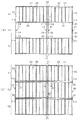
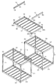
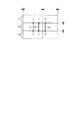
次に、中間構造部X3及びそれに関わる構成について説明する。図3は、建物本体12の躯体をユニット妻面側から見た正面図であり、図4は、躯体の平面構成を示す平面図である。図4において、(a)には一階天井面の構成を示し、(b)には一階/二階床面の構成を示している。また、図5は、建物本体12の主たる構成要素を分解して示す斜視図である。
Next, the intermediate structure portion X3 and the configuration related thereto will be described. FIG. 3 is a front view of the housing of the
図3に示すように、ユニット構造部X1,X2では、上下二段に建物ユニット20が積層配置されており、下階側の建物ユニット20の天井仕口21bの上方に上階側の建物ユニット20の床仕口21cが載置されるとともに、それら天井仕口21bと床仕口21cとが連結されることで、上下二段の建物ユニット20同士の連結がなされている。なお、以下の説明では便宜上、一階部分の建物ユニット20を「下階ユニット20A」、二階部分の建物ユニット20を「上階ユニット20B」とも称する。
As shown in FIG. 3, in the unit structures X1 and X2, the
ここで、上下方向に並ぶ建物ユニット20同士、及び水平方向に並ぶ建物ユニット20同士は、各建物ユニット20の仕口21b,21cにドッキングプレート29が設置されることで連結されるようになっている。この場合、下階ユニット20A及び上階ユニット20Bの境界部(一階及び二階の階間部分)では、1つのドッキングプレート29により建物ユニット20の上下連結がなされることに加え、水平連結がなされている。また、上階ユニット20Bの上面部では、1つのドッキングプレート29により建物ユニット20の水平連結がなされている。こうした建物ユニット20同士の連結手法は既存のユニット工法として知られている。
Here, the
また、中間構造部X3は、一対のユニット構造部X1,X2に挟まれて構築されており、中間構造部X3には、その天井部を構築するための中間天井梁ユニット31と、床部を構築するための床フレーム32とが設けられている。
The intermediate structure portion X3 is constructed by being sandwiched between a pair of unit structure portions X1 and X2. The intermediate structure portion X3 includes an intermediate
図3,図4(a)に示すように、中間天井梁ユニット31は、中間構造部X3を挟んで対向する2つの建物ユニット20の間に架け渡して設けられており、一階天井部と二階天井部とには同様の構成の中間天井梁ユニット31が設けられている。中間天井梁ユニット31は、離し置きされた両建物ユニット20の天井仕口21bにそれぞれ連結された、支持部材としての片持ち状(キャンチ構造)の支持梁33と、一対の支持梁33の間に設けられる中間天井梁34とを有して構成されている。なお、一階天井部分の支持梁33は床受け梁として機能する。中間天井梁34は、建物ユニット20の妻面に相当する部位に設置されるものであり、この意味からすれば天井妻梁となっている。
As shown in FIG. 3 and FIG. 4A, the intermediate
図3,図4(b)に示すように、一階床部及び二階床部はそれぞれ、矩形フレーム状に形成された床フレーム32を設置することで構成されている。ここで、一階床部分では、基礎11の天端上に載置されることで床フレーム32が設置されている。この場合、一階床部分の床フレーム32は、基礎11からその上方に延びるアンカーボルト(図示略)を利用して固定される構成となっている。これは、基礎11に対する建物ユニット20の固定方法と同様である。また、二階床部分では、中間天井梁ユニット31の上に載せられることで床フレーム32が設置されている。
As shown in FIGS. 3 and 4B, the first floor part and the second floor part are each configured by installing a
床フレーム32は、基本的に建物ユニット20の床部分と同様の構成を有するものであり、その構成を図5を参照しながら説明する。図5に示すように、床フレーム32は、その四隅に配設される4本の柱レス仕口36と、各柱レス仕口36をそれぞれ連結する4本の床フレーム大梁37とを備える。そして、それら柱レス仕口36と床フレーム大梁37により矩形状のフレーム本体が形成され、その長辺部(桁部)の相対する床フレーム大梁37の間に所定間隔で複数の床小梁38が架け渡されて固定されている。床フレーム大梁37及び床小梁38は建物ユニット20のそれと同じ構成を有する。すなわち、床フレーム大梁37はユニット床大梁23と同じ溝形鋼よりなり、その開口部が向き合うようにして設置されている。床小梁38は床小梁26と同じ角形鋼よりなり、その床小梁26と同じピッチで設置されている。そして、床小梁38によって床面材(図示略)が支持されるようになっている。
The
床フレーム32の構成を建物ユニット20の床部の構成と対比すると、その違いは、床仕口21cの代わりに柱レス仕口36が設けられる点である。柱レス仕口36は、2つの床フレーム大梁37を接合するための2つの仕口板部36aと、その底部に設けられた底板部36bとを有する。2つの仕口板部36aは端部同士が直角に接合され、その頂部をユニット内側に向けて配置されている。底板部36bは、床仕口21cの柱脚プレート部(図10のエンドプレート65)に相当する部材である。
When the configuration of the
床フレーム32は、基本的には建物ユニット20の床部構成と同じ構成を有しているため、床小梁材や床面材など、床構成部の各種建材を共通化でき、部品製造の観点、施工作業性の観点からして好都合な構成となっている。
Since the
図3に示すように、ユニット構造部X1,X2と中間構造部X3とでは、建物ユニット20の床大梁23の高さ位置と、床フレーム大梁37の高さ位置とが同じであり、それ故に、床面の高さ位置を同一にできるようになっている。また、中間構造部X3では、一階部分及び二階部分の両方において柱レス構造となっており、その分、屋内空間の拡張が可能となっている。すなわち、例えば図4のY部は、通常のユニット工法では4本の柱が集結する部位であるが、本建物10では、2本の柱のみが集結する構成となっている。
As shown in FIG. 3, in the unit structure portions X1, X2 and the intermediate structure portion X3, the height position of the
次に、中間構造部X3において建物ユニット20の天井仕口21bとの連結部分における詳細な構成を、図6〜図13を用いて説明する。
Next, the detailed structure in the connection part with the
図6は、建物ユニット20の天井仕口21bの構成を示す図であり、(a)は平面図、(b)は側面図である。天井仕口21bには二方に天井大梁22が連結されており、そのうち妻側の天井大梁22とは反対側の仕口面には連結金具としての梁連結ブラケット41が固定されている。梁連結ブラケット41が固定される仕口面は、建物ユニット20の内通り天井仕口面である。なお、天井仕口21bには柱本体21aとの連結部(天井仕口21bの下端部)において裏当て金が設けられるが、便宜上図示を省略している。
6A and 6B are diagrams showing the configuration of the ceiling joint 21b of the
梁連結ブラケット41は、略コ字状をなす鋼板により構成されており、両端部が天井仕口21bの仕口面に溶接等により固定されている。梁連結ブラケット41には、天井仕口21bの仕口面に平行となる梁取付面42が形成されており、その梁取付面42に通じるボルト孔43が形成されるとともに、梁取付面42の裏側(仕口面側)にはボルト孔43に同軸で複数個のナット44が固定されている。
The
梁連結ブラケット41は、ユニット製造工場において建物ユニット20の天井仕口21bに溶接固定(先付け)されるものであり、天井仕口21bからの突出高さは、施工現場へのユニット輸送作業を考慮した寸法となっている。この場合、梁連結ブラケット41は、隣接する2ユニットを結合した場合のドッキングラインDLを超えない突出高さを有するものとなっており、本実施形態では、梁連結ブラケット41の突出高さを、仕口面からドッキングラインDLまでの寸法としている。具体的には、梁連結ブラケット41の厚み方向の幅(張出寸法)は最大でも30mm程度であり、これにより、当該ブラケット41が工場先付けとされる場合にも、ユニット寸法が道路交通法の輸送制限を超えてしまうといった不都合が回避できるものとなっている。
The
なお、図6に示すドッキングラインDLは、実際には建物ユニット20同士を結合させるユニット境界線ではないが、本実施形態の建物自体、既存のユニット工法を極力流用しようとするものであり、ユニット構造部X1,X2と中間構造部X3との境界部分にもドッキングラインDLが設定されている。
Note that the docking line DL shown in FIG. 6 is not actually a unit boundary line that connects the
図6(a)に示すように、天井仕口21bの上面部に設けられたエンドプレート45(柱頭プレート部)には、ドッキングプレート29を用いた建物ユニット20同士の連結に使用するためのピン孔46,47が形成されている。
As shown in FIG. 6A, the end plate 45 (capital plate portion) provided on the upper surface portion of the ceiling joint 21b is a pin used for connecting the
図7は、梁連結ブラケット41に中間天井梁ユニット31を連結した状態を示す図であり、(a)は平面図、(b)は側面図である。図8は、中間天井梁ユニット31の構成を示す分解斜視図である。
7A and 7B are views showing a state in which the intermediate
図7,図8に示すように、中間天井梁ユニット31において、中間天井梁34の両端には継手プレート51を介して一対の支持梁33が連結されている。支持梁33及び中間天井梁34はいずれも建物ユニット20の天井大梁22と同じ溝形鋼で構成され、そのウェブ部同士が継手プレート51により連結されている。図7においては、天井仕口21bの梁連結ブラケット41に対して支持梁33が固定され、その支持梁33の自由端側に中間天井梁34が連結される構成となっている。
As shown in FIGS. 7 and 8, in the intermediate
ここで、継手プレート51は、一部が中間天井梁34からはみ出た状態で中間天井梁34のウェブ部に溶接等により固定され、そのはみ出し部分が、支持梁33のウェブ部に接合されてボルト52等により固定されるようになっている。継手プレート51の中間天井梁34からのはみ出し部分には、しの孔53が形成されており、現場において中間天井梁34を組み付ける際の作業性向上が図られている。
Here, the
継手プレート51においてボルト52が差し入れられるボルト挿入孔51aは、中間天井梁34の長手方向に延びる長孔になっているとよい。これにより、中間天井梁34を支持梁33に連結した状態で、中間天井梁ユニット31の長さの微調整が可能となっている。なお、継手プレート51及び支持梁33の連結部では少なくともいずれか一方のボルト挿入孔が長孔になっていればよい。
The
図示は省略しているが、中間天井梁34には、建物ユニット20の天井大梁22と同様に、空調ダクト等を挿通させる梁貫通孔や、外壁パネルを固定するための外壁固定孔が形成されている。中間天井梁34は、基本的にユニット天井大梁22と構成が同じであるため、中間構造部X3用に新規に外壁パネルを設計することは不要であり、また、建物ユニット20側と同様の工法で外壁パネルの設置が可能となっている。
Although not shown, the
支持梁33の溝形鋼の端面部には溶接等により端面プレート54が固定されている。この端面プレート54は、支持梁33を梁連結ブラケット41の梁取付面42に接合させるための部位であり、端面プレート54には、梁連結ブラケット41のボルト孔43に通じる貫通孔54aが形成されている。梁連結ブラケット41に対して支持梁33を接合させた状態で、貫通孔54a及びボルト孔43にボルト55が螺着されることで、梁連結ブラケット41に支持梁33が連結固定される。
An end face
支持梁33の上側フランジ部にはベースプレート56が設置されている。ベースプレート56は、支持梁33において天井仕口21bのエンドプレート45と同様の構成及び機能を持たせるものであり、天井仕口21bのエンドプレート45と同様に、ドッキングプレート29による連結に使用するためのピン孔57,58が形成されている。一方、支持梁33の上側フランジ部には、ベースプレート56のピン孔57に対応する位置にピン孔59が形成されている。そして、支持梁33の上側フランジ部にベースプレート56が固定されるとともに、支持梁33のピン孔59とベースプレート56のピン孔57とに下方からスタッキングピン61が挿通され固定されている。一方、天井仕口21bのエンドプレート45には、上方に延びる向きでスタッキングピン62が取り付けられている(これは従来同様)。
A
図7に示す構成では、支持梁33上のベースプレート56の上面と、天井仕口21bのエンドプレート45の上面とが同じ高さとなっている。また、ドッキングラインDLを挟んで対称位置に2つのスタッキングピン61,62が設置されており、ドッキングラインDLからの距離L1,L2はL1=L2となっている。
In the configuration shown in FIG. 7, the upper surface of the
本実施形態においては、構造力学上は支持梁33がその上部構造(床フレーム32等)の荷重を梁連結ブラケット41を介して隣接するユニット柱に伝達するものとなっている。
In the present embodiment, in terms of structural mechanics, the
図9は、天井仕口21b及び支持梁33にドッキングプレート29を取り付けた状態を示す図であり、(a)は平面図、(b)は側面図である。
FIGS. 9A and 9B are views showing a state in which the
ドッキングプレート29は、支持梁33上のベースプレート56と天井仕口21bのエンドプレート45とのほぼ全体を覆う大きさを有し、下方に向けて突出する一対のスタッキングピン63,64が取り付けられている。そして、ベースプレート56とエンドプレート45との上にドッキングプレート29が設置され、その際、ドッキングプレート29のスタッキングピン63,64が天井仕口21bのピン孔47とベースプレート56のピン孔58とに差し込まれるようになっている。この場合、ドッキングラインDLを挟んで対称位置に2つのスタッキングピン63,64が設置される構成となっており、ドッキングラインDLからの距離L3,L4はL3=L4となっている。
The
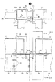
図10は、下階ユニット20Aの上に上階ユニット20Bを設置するとともに、支持梁33の上に床フレーム32を設置した状態を示す図であり、(a)は平面図、(b)は側面図である。
FIG. 10 is a diagram showing a state in which the
図10に示すように、支持梁33の上方であってドッキングプレート29上には床フレーム32が設置されている。この場合詳しくは、床フレーム32の柱レス仕口36がドッキングプレート29上に設置されるとともに、柱レス仕口36の底板部36bに形成されたピン孔36cにスタッキングピン61が差し込まれている。また、複数箇所でのボルト67の締結により、床フレーム32が支持梁33に対して固定されている。これにより、建物ユニット20の天井仕口21bに接続された支持梁33に床フレーム32が接合される構成となっている。
As shown in FIG. 10, a
一方、下階ユニット20Aの上方であってドッキングプレート29上には上階ユニット20Bが設置されている。この場合詳しくは、上階ユニット20Bの床仕口21cがドッキングプレート29上に設置されるとともに、床仕口21cのエンドプレート65に形成されたピン孔65aにスタッキングピン62が差し込まれている。また、複数箇所でのボルト68の締結により、上階ユニット20Bが下階ユニット20Aに対して固定されている。なお、柱レス仕口36の底板部36bのピン孔36cと、床仕口21cのエンドプレート65のピン孔65aとは、ドッキングラインDLを挟んで対称位置に設けられている。
On the other hand, the
ここで、一階天井面においては床フレーム32が配置されることで、建物10に水平力が入力された時に水平構面伝達を二階の床フレーム32で処理することが可能であるが、二階天井面においては床フレーム32が設置されていない。そこで本実施形態では、二階天井面での水平力を処理するべく建物ユニット間に水平ブレース76が配置されている。
Here, the
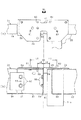
図11は、二階天井面における躯体の平面構成を示す平面図であり、図12は、水平ブレース76の連結部を拡大して示す平面図である。
FIG. 11 is a plan view showing a planar configuration of the frame on the second-floor ceiling surface, and FIG. 12 is an enlarged plan view showing a connecting portion of the
図11,図12に示すように、建物ユニット20(上階ユニット20B)の天井大梁22のウェブ外側面には、天井大梁22の長手方向の中間位置にブラケット71を介して天井束受梁72が連結されている。天井束受梁72は例えば溝形鋼よりなる。天井束受梁72は、中間構造部X3において、対向配置される建物ユニット20の間に架け渡して設けられている。
As shown in FIGS. 11 and 12, on the outer surface of the web of the
また、天井束受梁72には、屋根を支持するための束73が立設されている。詳しくは、建物ユニット20の天井大梁22と天井束受梁72との上面には、それら両者に跨るようにしてベースプレート74が固定され、そのベースプレート74の上面に束73が固定されている。この場合、束73はドッキングラインDL上に立設される構成となっている。図13は二階天井面における束73の設置位置を示す平面図であり、同図では束73の設置位置をTとしている。本実施形態の場合、二階天井面において計6カ所に束73が設けられている。
The ceiling
二階天井面には水平ブレース76が設けられている。詳しくは、建物ユニット20の天井大梁22のウェブ外側面には複数箇所にブラケット75が固定されており、そのブラケット75を被支持端部として水平ブレース76がX字状に配設されている。水平ブレース76はボルト接合によりブラケット75に対して固定されている。本実施形態では、天井大梁22において天井仕口21b付近と天井束受梁72付近とにブラケット75が設けられ、一対二組の対向配置ユニットの間に、それぞれ二組ずつの水平ブレース76が配設されている。本構成では、水平ブレース76により二階天井面の水平構面伝達力が確保されている。なお、水平ブレース76には、張力を調整する調整機構としてのターンバックル77が取り付けられている。
A
図11に示すように、二階天井面において各一対の建物ユニット20で挟まれた中間部分はそれぞれ複数に分割されており、その分割領域ごとに略対角線状に水平ブレース76が配置されている。天井束受梁72は、水平ブレース76の反力を受ける反力受梁としての機能を有している。
As shown in FIG. 11, the intermediate portion sandwiched between each pair of building
次に、本実施形態における建物10について施工現場での施工手順について説明する。図14は、施工現場での建物施工手順を示す説明図である。
Next, the construction procedure at the construction site for the
設置現場での施工に際し、図14(a)に示すように、まずは、基礎11上に一階用の床フレーム32を設置するとともに、床フレーム32を挟んでその両側に複数の下階ユニット20Aを離し置きする。このとき、中間構造部X3に隣接することになる下階ユニット20Aについては、内通り天井仕口面に梁連結ブラケット41が位置するように配置する。なお、梁連結ブラケット41はユニット製造工場にて先付けされている。下階ユニット20A及び一階用の床フレーム32の設置に際してはこれらをアンカーボルトにより基礎11に対して固定する。下階ユニット20A及び床フレーム32の設置順序は任意である。そして、床フレーム32上に床面材等を適宜設置する。
In the construction at the installation site, as shown in FIG. 14A, first, a
次に、図14(b)に示すように、対向配置された下階ユニット20Aの天井仕口21bの間に架け渡すようにして中間天井梁ユニット31を設置する。このとき、中間天井梁ユニット31を構成する支持梁33と中間天井梁34とのうち、支持梁33を先に梁連結ブラケット41に対して固定し、その後、離間配置された一対の支持梁33に対して中間天井梁34を固定する。そして、天井仕口21b及び支持梁33(詳しくはベースプレート56)に対してドッキングプレート29を取り付ける。
Next, as shown in FIG. 14 (b), the intermediate
その後、図14(c)に示すように、一階天井部分の中間天井梁ユニット31の上に二階用の床フレーム32を設置する。このとき、床フレーム32の荷重は実質的に支持梁33にて支えられる。そして、床フレーム32上に床面材等を適宜設置する。
Then, as shown in FIG.14 (c), the
その後、図14(d)に示すように、下階ユニット20Aの上に上階ユニット20Bを設置する。
Then, as shown in FIG.14 (d), the
その後、図14(e)に示すように、対向配置された上階ユニット20Bの天井仕口21bの間に架け渡すようにして中間天井梁ユニット31を設置する。このとき、中間天井梁ユニット31を構成する支持梁33と中間天井梁34とのうち、支持梁33を先に梁連結ブラケット41に対して固定し、その後、離間配置された一対の支持梁33に対して中間天井梁34を固定する。
Then, as shown in FIG.14 (e), the intermediate | middle
また、図14(f)に示すように、二階天井面において、対向配置された上階ユニット20Bの天井大梁22の間に天井束受梁72を取り付けるとともに、天井大梁22及び天井束受梁72により囲まれた水平面内に水平ブレース76を取り付ける(図11参照)。なお、水平ブレース76を取り付けるためのブラケット75はユニット製造工場にて先付けされている。さらに、天井束受梁72の上に束73を立設するとともに、天井束受梁72上の束73に支持させた状態で屋根材78を設置する。こうした作業により、ユニット離隔配置工法の建物10が構築される。
Further, as shown in FIG. 14 (f), on the second floor ceiling surface, a ceiling
以上詳述した本実施形態によれば、以下の優れた効果が得られる。 According to the embodiment described in detail above, the following excellent effects can be obtained.
対向配置される建物ユニット20の天井仕口21bに中間スペース側(ユニット離し置き部分)に延びる向きで支持梁33を設け、その支持梁33により、中間構造部X3を構成する床フレーム32を支持する構成とした。この場合、支持梁33は、床フレーム32を支持する上で固定荷重及び積載荷重に対する大きさ及び強度を有していれば足り、建物ユニット20や中間構造部X3の大きさに依存しないものとなっている。ゆえに、ユニット天井大梁に沿って延びる連結梁(ジョイントビーム)により床パネルを固定する従来技術と対比すると、同従来技術では、建物ユニット20の大きさに合う長さの連結梁を用意する必要があるのに対し、本実施形態では、建物ユニット20の大きさに関係なく共通の支持梁33を用いることが可能となる。その結果、ユニット離隔配置工法の建物10において、中間構造部X3を構築する上での施工作業性を大いに向上させることができる。
A
対向配置された各建物ユニット20の内通りに支持梁33を片持ち梁としてそれぞれ設け、それら各支持梁33に跨る状態で床フレーム32を設置する構成としたため、中間構造部X3における強度計算は支持梁33について行われればよく、構造設計を容易に実施できる。また、支持梁33は、建物ユニット20の柱21ごとに設けられ、換言すれば柱21の数だけ用意されれば足りるものである。ゆえに、柱21の数以上に支持梁33を用意する必要はなく、中間構造部X3を構築する上での構成の簡素化を図ることが可能となる。
Since the support beams 33 are provided as cantilever beams on the inner streets of the opposingly arranged
支持梁33により支持される床フレーム32は建物ユニット20に比べると軽量であるため、支持梁33を経由して建物ユニット20の柱21に伝達される鉛直荷重(固定荷重・積載荷重)は建物ユニット20よりも小さくなる。そのため、支持梁33の天井仕口21bに対する接合手法として、梁連結ブラケット41に対して複数箇所でボルト連結するといった比較的簡易な手法を用いればよい。
Since the
中間天井梁ユニット31として、一対の支持梁33の間に、中間構造部X3において外壁パネルを固定するための中間天井梁34を設けたため、この中間天井梁34を用いて、中間構造部X3においても建物ユニット20と同様に外壁パネルを設置できる。この場合、中間天井梁34は、建物ユニット20の天井大梁22と同様の溝形鋼で構成されているため、建物ユニット20に対して外壁パネルを設置するのと同じ手法で、中間構造部X3において外壁パネルを設置できる。ゆえに、中間構造部X3用の外壁パネルを新規に設計することが不要となり、設計工数の削減を図ることもできる。
Since the
中間構造部X3において、その両サイドに支持梁33が離間して設けられることで、地震時において中間構造部X3がホイッピングのような挙動となることを抑制できる。 In the intermediate structure portion X3, the support beams 33 are separately provided on both sides of the intermediate structure portion X3, so that the intermediate structure portion X3 can be prevented from acting like whipping during an earthquake.
中間構造部X3を構成する支持梁33を、建物ユニット20の天井仕口21bと同様の構成を有するものとした。具体的には、支持梁33において、天井仕口21bのエンドプレート45の構成に合わせてベースプレート56を設け、さらにそのベースプレート56の設置高さを天井仕口21bのエンドプレート45と同じにした。この場合、既存のユニット工法において建物ユニット20の天井仕口同士を連結したり、下階ユニットの天井仕口に上階ユニットの床仕口を連結したりするのと同様の構成を、ユニット構造部X1,X2(建物ユニット20)と中間構造部X3との境界部においても実現できる。ユニット工法で用いるドッキングプレート29の流用も可能となっている。
The
中間構造部X3の床構造体として、建物ユニット20の床部分と同様の構成を有する床フレーム32を設置するようにしたため、建物ユニット20同士を連結するのと同様に、ドッキングプレート29を用いて支持梁33とその上方の床フレーム32とを連結できる。この場合、部品の共通化を図ることができる。
Since the
対向配置された各建物ユニット20の天井大梁22に挟まれた中間構造部X3の天井面に、その両天井大梁22に架け渡して水平ブレース76を設けたため、中間構造部X3の天井面において水平構面伝達を水平ブレース76を介して好適に行わせることができる。本実施形態の建物10では、中間構造部X3の床部分においては床フレーム32により水平力に対する抗力を十分に発揮できるが、天井部分(二階天井部分)においてはそれができない。この点、中間構造部X3の二階天井部分に水平ブレース76を設置したため、その二階天井部分でも水平力に対する抗力を十分に確保できる。
Since the
建物ユニット20の天井仕口21bに、ユニット外側に向けて延びドッキングラインDLを超えない突出高さを有する梁連結ブラケット41をユニット製造工場にて先付けしておき、その梁連結ブラケット41に支持梁33を固定する構成とした。そのため、施工現場では、建物ユニット20に対する支持梁33の固定に関して作業を容易にすることができる。つまり、梁連結ブラケット41を工場先付けしておきその梁連結ブラケット41に対して支持梁33を固定する手法によれば、施工現場で建物ユニット20のどの位置に支持梁33を固定するかの位置決め作業等が容易となる。また、梁連結ブラケット41はドッキングラインDLを超えない突出高さを有するものであるため、施工現場への建物ユニット20の搬送に際して寸法規制に関する支障を来すことを抑制できる。
A
[他の実施形態]
本発明は上記実施形態の記載内容に限定されず、例えば次のように実施されてもよい。
[Other Embodiments]
The present invention is not limited to the description of the above embodiment, and may be implemented as follows, for example.
・上記実施形態では、一階天井面及び二階天井面において、中間構造部X3の天井梁構造として、支持梁33と中間天井梁34とを有する中間天井梁ユニット31を用いたが、この構成を変更してもよい。この場合、一対の支持梁33の間に設けられる壁固定用横架材としての中間天井梁34は、建物ユニット20の天井大梁22と同じ溝形鋼でなくてもよく、それよりも剛性の低い鋼材、例えば軽量形鋼を用いて構成してもよい。要するに、中間天井梁34は、建物10の構造強度を補償するものではなく、主に外壁パネルを固定する目的で設けられており、中間構造部において壁部材の固定が可能なものであればよい。
In the above embodiment, the intermediate
中間天井梁34が壁固定の横架材として用いられる以外に、天井固定用の横架材として用いられる構成であってもよい。この場合、例えば、中間天井梁34に野縁が固定されるとともに、その野縁により天井面材が固定される構成とする。
The
また、支持梁33についても、溝形鋼以外で構成されることも可能である。例えば、H形鋼や角形鋼により構成されていてもよい。
Further, the
・一対の支持梁33の間において中間天井梁34を設けない構成であってもよい。つまり、図15に示す構成とする。図15では、図3等と同様にユニット天井仕口21bに支持梁33を片持ち状態で設けるが、中間天井梁34は設けない構成としている。この場合、建物10の外面部に相当する部位には当然ながら外壁部材が設置されるが、その外壁部材自体の構造及び取り付け構造が、通常の建物ユニット20のそれとは異なるものであるとよい。なお、二階部分において支持梁33の上に床フレーム32が載置され固定される構成は、上記実施形態と同様である。
-The structure which does not provide the intermediate |
壁部材を取り付ける必要のない部分では、壁固定用横架材が不要であり、その意味からしても中間天井梁34は必須ではない。要するに、中間構造部X3の天井梁として、中間天井梁34を設ける部分と中間天井梁34を設けない部分とが混在する構成であってもよい。
In a portion where it is not necessary to attach the wall member, the wall fixing horizontal member is unnecessary, and the
・上記実施形態では、建物ユニット20の天井仕口21bに支持部材としての片持ち梁(支持梁33)を連結する構成としたが、これを変更してもよい。例えば、建物ユニット20の床仕口21cに片持ち梁を設ける構成とする。又は、建物ユニット20の天井大梁22又は床大梁23に片持ち梁を設ける構成とする。
In the above embodiment, the cantilever (support beam 33) as a support member is connected to the
さらに、建物ユニット20の柱本体21a(すなわち柱21の中間部分)に片持ち梁を設ける構成としてもよい。この場合、中間構造部X3において、片持ち梁に支持させた状態でスキップ床を形成することができる。
Furthermore, it is good also as a structure which provides a cantilever in the column
・上記実施形態では、建物ユニット20の天井仕口21bに梁連結ブラケット41を先付けしておき、その梁連結ブラケット41に支持梁33を固定する構成としたが、これを変更し、梁連結ブラケット41を使わずに、支持梁33を直接天井仕口21bに固定する構成であってもよい。
In the above embodiment, the
・本発明が適用される建物は、上述した構成の建物10に限定されない。例えば、多層階建物に代えて、平屋建物に適用されてもよい。平屋建物の場合、支持部材としての片持ち梁により、上部構造体としての小屋裏部分又は屋根部分の構造体が支持されるとよい。
-The building to which this invention is applied is not limited to the
10…建物、12…建物本体、20…建物ユニット、21…柱、21b…天井仕口、21c…床仕口、22…天井大梁、23…床大梁、29…ドッキングプレート(ユニット連結プレート)、31…中間天井梁ユニット、32…床フレーム、33…支持梁(支持部材)、34…中間天井梁(壁固定用横架材)、36…柱レス仕口(フレーム仕口)、36b…底板部(底プレート部)、37…床フレーム大梁、41…梁連結ブラケット(連結金具)、45…エンドプレート(柱頭プレート部)56…ベースプレート(支持プレート部)、65…エンドプレート(柱脚プレート部)、76…水平ブレース、DL…ドッキングライン(ユニット境界線)、X1,X2…ユニット構造部、X3…中間構造部。
DESCRIPTION OF
Claims (6)
対向配置される建物ユニットにおいて前記ユニット柱又は前記ユニット大梁には、前記中間部分側に延びる向きで支持部材が設けられ、該支持部材により、それより上部側に設けられる上部構造体が支持されている構成を有するものであって、
前記支持部材は、前記ユニット柱に設けられた天井仕口においてユニット天井大梁とは逆側の仕口面に設けられ、前記天井仕口の上端部に設けられた柱頭プレート部と同じ高さ位置に、前記上部構造体を載置支持する支持プレート部が固定されていることを特徴とする建物。 A plurality of building units having a plurality of unit columns and unit beams connected to the unit columns are provided, and the building units are separated from each other. It is a building where intermediate structures with different configurations are provided,
In the building unit arranged oppositely, the unit column or the unit beam is provided with a support member extending in the direction of the intermediate portion, and the upper member is supported by the support member on the upper side. And having a configuration
The support member is provided on a joint surface opposite to the unit ceiling beam in a ceiling joint provided on the unit column, and is at the same height as a stigma plate portion provided on an upper end portion of the ceiling joint. And a support plate portion for mounting and supporting the upper structure is fixed to the building.
前記上部構造体として、複数の床フレーム大梁とそれらを連結するフレーム仕口とを有する床フレームを備え、
前記フレーム仕口には、前記建物ユニットの床仕口の下端部に設けられた柱脚プレート部と同じ形態の底プレート部が設けられており、
前記支持部材の支持プレート部と前記フレーム仕口の底プレート部とが上下となる位置に前記床フレームが配置され、前記ユニット連結プレートを介して前記支持プレート部と前記底プレート部とが連結されている請求項1に記載の建物。 The upper floor building unit is placed on the lower floor building unit, and the ceiling joint of the lower floor building unit and the floor joint of the upper floor building unit are connected via a unit connecting plate. A multi-storey building
As the upper structure, comprising a floor frame having a plurality of floor frame girder and a frame joint connecting them,
The frame joint is provided with a bottom plate portion having the same form as a column base plate portion provided at a lower end portion of a floor joint of the building unit,
The floor frame is disposed at a position where the support plate portion of the support member and the bottom plate portion of the frame joint are vertically positioned, and the support plate portion and the bottom plate portion are connected via the unit connection plate. The building according to claim 1 .
前記支持部材は、前記連結金具を介して前記ユニット柱又は前記ユニット大梁に連結されている請求項1又は2に記載の建物。 In the unit pillar or the unit beam, a connecting metal fitting extending to the outside of the unit and having a protruding height that does not exceed the unit boundary line that becomes a boundary line when adjacent building units are joined to each other in the unit manufacturing factory. Fixed,
The support member, the building according to claim 1 or 2 via the connecting fitting is connected to the unit column or the unit girder.
それら各片持ち梁に跨る状態で前記上部構造体が設置されている請求項1乃至3のいずれか一項に記載の建物。 In the building units arranged opposite to each other, the unit column of each building unit is provided with a cantilever as the support member in a direction extending from one building unit to the other building unit,
The building according to any one of claims 1 to 3 , wherein the upper structure is installed in a state of straddling each cantilever.
Priority Applications (1)
| Application Number | Priority Date | Filing Date | Title |
|---|---|---|---|
| JP2010071740A JP5667775B2 (en) | 2010-03-26 | 2010-03-26 | building |
Applications Claiming Priority (1)
| Application Number | Priority Date | Filing Date | Title |
|---|---|---|---|
| JP2010071740A JP5667775B2 (en) | 2010-03-26 | 2010-03-26 | building |
Publications (2)
| Publication Number | Publication Date |
|---|---|
| JP2011202438A JP2011202438A (en) | 2011-10-13 |
| JP5667775B2 true JP5667775B2 (en) | 2015-02-12 |
Family
ID=44879350
Family Applications (1)
| Application Number | Title | Priority Date | Filing Date |
|---|---|---|---|
| JP2010071740A Active JP5667775B2 (en) | 2010-03-26 | 2010-03-26 | building |
Country Status (1)
| Country | Link |
|---|---|
| JP (1) | JP5667775B2 (en) |
Families Citing this family (2)
| Publication number | Priority date | Publication date | Assignee | Title |
|---|---|---|---|---|
| JP2015086600A (en) * | 2013-10-31 | 2015-05-07 | 株式会社サトコウ | Unit structure |
| JP2018053554A (en) * | 2016-09-29 | 2018-04-05 | 積水化学工業株式会社 | Unit Building |
Family Cites Families (3)
| Publication number | Priority date | Publication date | Assignee | Title |
|---|---|---|---|---|
| JPS59106641A (en) * | 1982-12-09 | 1984-06-20 | 積水化学工業株式会社 | Unit house |
| JPH08177127A (en) * | 1994-12-21 | 1996-07-09 | Sekisui Chem Co Ltd | Unit building |
| JP5478864B2 (en) * | 2008-10-01 | 2014-04-23 | ミサワホーム株式会社 | Connection structure, unit type building, construction method |
-
2010
- 2010-03-26 JP JP2010071740A patent/JP5667775B2/en active Active
Also Published As
| Publication number | Publication date |
|---|---|
| JP2011202438A (en) | 2011-10-13 |
Similar Documents
| Publication | Publication Date | Title |
|---|---|---|
| JP5833564B2 (en) | Paneled structural system for building | |
| JP4583778B2 (en) | Unit building | |
| JP2011202439A (en) | Building unit | |
| JP5953016B2 (en) | Attached structures and unit buildings | |
| JP5362310B2 (en) | Unit building | |
| JP5667775B2 (en) | building | |
| JP5693867B2 (en) | building | |
| JP5836077B2 (en) | Attached structures and unit buildings | |
| JP3796462B2 (en) | Unit building | |
| JP2018104884A (en) | Reinforcing structure and reinforcing method of building | |
| JP5004434B2 (en) | Steel house | |
| JP2011052507A (en) | Low-story building | |
| JP5053137B2 (en) | Unit building | |
| JP7316176B2 (en) | unit building | |
| JP6122980B2 (en) | Attached structures and unit buildings | |
| JP7358142B2 (en) | unit building | |
| JP6739175B2 (en) | Bonding structure of building structural material and face material | |
| JP2020002631A (en) | Column-beam joint structure | |
| JP2524409B2 (en) | House of frame, panel construction method | |
| JP7303712B2 (en) | unit building | |
| JP4205884B2 (en) | Unit building | |
| JP2023057702A (en) | Seismic isolation and earthquake-resistant structure of combined wooden and light-framed building | |
| JP2022054706A (en) | Column connection structure of building unit | |
| JP2020147986A (en) | Connection structure of building unit | |
| JP5749610B2 (en) | Unit building |
Legal Events
| Date | Code | Title | Description |
|---|---|---|---|
| A621 | Written request for application examination |
Free format text: JAPANESE INTERMEDIATE CODE: A621 Effective date: 20130117 |
|
| A977 | Report on retrieval |
Free format text: JAPANESE INTERMEDIATE CODE: A971007 Effective date: 20131107 |
|
| A131 | Notification of reasons for refusal |
Free format text: JAPANESE INTERMEDIATE CODE: A131 Effective date: 20131112 |
|
| A521 | Request for written amendment filed |
Free format text: JAPANESE INTERMEDIATE CODE: A523 Effective date: 20131209 |
|
| A131 | Notification of reasons for refusal |
Free format text: JAPANESE INTERMEDIATE CODE: A131 Effective date: 20140520 |
|
| A521 | Request for written amendment filed |
Free format text: JAPANESE INTERMEDIATE CODE: A523 Effective date: 20140716 |
|
| TRDD | Decision of grant or rejection written | ||
| A01 | Written decision to grant a patent or to grant a registration (utility model) |
Free format text: JAPANESE INTERMEDIATE CODE: A01 Effective date: 20141209 |
|
| A61 | First payment of annual fees (during grant procedure) |
Free format text: JAPANESE INTERMEDIATE CODE: A61 Effective date: 20141215 |
|
| R150 | Certificate of patent or registration of utility model |
Ref document number: 5667775 Country of ref document: JP Free format text: JAPANESE INTERMEDIATE CODE: R150 |
|
| R250 | Receipt of annual fees |
Free format text: JAPANESE INTERMEDIATE CODE: R250 |
|
| R250 | Receipt of annual fees |
Free format text: JAPANESE INTERMEDIATE CODE: R250 |
|
| R250 | Receipt of annual fees |
Free format text: JAPANESE INTERMEDIATE CODE: R250 |
|
| R250 | Receipt of annual fees |
Free format text: JAPANESE INTERMEDIATE CODE: R250 |
|
| R250 | Receipt of annual fees |
Free format text: JAPANESE INTERMEDIATE CODE: R250 |