JP6739175B2 - Bonding structure of building structural material and face material - Google Patents

Bonding structure of building structural material and face material Download PDF

Info

Publication number
JP6739175B2
JP6739175B2 JP2016008167A JP2016008167A JP6739175B2 JP 6739175 B2 JP6739175 B2 JP 6739175B2 JP 2016008167 A JP2016008167 A JP 2016008167A JP 2016008167 A JP2016008167 A JP 2016008167A JP 6739175 B2 JP6739175 B2 JP 6739175B2
Authority
JP
Japan
Prior art keywords
structural
joining
building
face
face material
Prior art date
Legal status (The legal status is an assumption and is not a legal conclusion. Google has not performed a legal analysis and makes no representation as to the accuracy of the status listed.)
Active
Application number
JP2016008167A
Other languages
Japanese (ja)
Other versions
JP2017128894A (en
Inventor
鶴田 修
修 鶴田
Current Assignee (The listed assignees may be inaccurate. Google has not performed a legal analysis and makes no representation or warranty as to the accuracy of the list.)
Misawa Homes Co Ltd
Original Assignee
Misawa Homes Co Ltd
Priority date (The priority date is an assumption and is not a legal conclusion. Google has not performed a legal analysis and makes no representation as to the accuracy of the date listed.)
Filing date
Publication date
Application filed by Misawa Homes Co Ltd filed Critical Misawa Homes Co Ltd
Priority to JP2016008167A priority Critical patent/JP6739175B2/en
Publication of JP2017128894A publication Critical patent/JP2017128894A/en
Application granted granted Critical
Publication of JP6739175B2 publication Critical patent/JP6739175B2/en
Active legal-status Critical Current
Anticipated expiration legal-status Critical

Links

Images

Description

本発明は、建物の構造材と面材の接合構造に関する。 The present invention relates to a joint structure of a structural material of a building and a face material.

特許文献1において、建物の構造材の間に耐力面材を架設する工法で、構造材の溝部に固定部材の楔形部を接着剤で接着嵌合した後、さらに固定部材をスクリュー釘で構造材に固定して、その固定部材に耐力面材をボルト結合する補強構造が提案される。 In Patent Document 1, in a construction method in which a load bearing surface material is erected between structural materials of a building, a wedge-shaped portion of a fixing member is adhesively fitted in a groove portion of the structural material, and then the fixing member is further structural member with a screw nail. A reinforcing structure is proposed in which a bearing surface material is bolted to the fixing member.

特開2007−284867号公報JP, 2007-284867, A

しかし、特許文献1のように、構造材の溝部に接着嵌合した固定部材を、さらにスクリュー釘で構造材に固定した構造では、リフォーム時や災害時に分解することは極めて困難であった。 However, with the structure in which the fixing member that is adhesively fitted in the groove portion of the structural material is further fixed to the structural material with the screw nail as in Patent Document 1, it is extremely difficult to disassemble at the time of reform or disaster.

本発明の課題は、建物のリフォーム時や災害時に簡単に分解可能な構造材と面材の接合構造を提供することである。 An object of the present invention is to provide a joint structure of a structural material and a face material, which can be easily disassembled when a building is reformed or a disaster occurs.

以上の課題を解決するため、請求項1に記載の発明は、例えば図1、図4及び図5に示すように、
建物の構造材3と、その構造材3の間に配置される面材4とを接合する接合部材5を用いる接合構造であって、
前記面材4と前記接合部材5とがボルト結合されており、
前記構造材3は前記接合部材5を挿通した挿通溝3aが設けられており、
前記接合部材5の前記挿通溝3aに挿通した挿通片5cと前記構造材3とにボルト11の貫通孔5d・3bが設けられており、
前記構造材3と接合部材5とが前記貫通孔5d・3bに通されたボルト11によって結合されており、
前記接合部材5は、前記構造材3に一面側が沿って前記面材4に他面側が沿う筒部材5aと、その筒部材5aに一体化して前記挿通片5cを有する板部材5bとからなることを特徴とする。
In order to solve the above problems, the invention described in claim 1 is, for example, as shown in FIG. 1, FIG. 4 and FIG.
A joining structure using a joining member 5 for joining a structural material 3 of a building and a face material 4 arranged between the structural materials 3,
The face member 4 and the joining member 5 are bolted to each other,
The structural member 3 is provided with an insertion groove 3a through which the joining member 5 is inserted,
Through-holes 5d and 3b of the bolt 11 are provided in the insertion piece 5c inserted into the insertion groove 3a of the joining member 5 and the structural member 3.
The structural member 3 and the joining member 5 are connected by a bolt 11 which is passed through the through holes 5d and 3b ,
The joining member 5 includes a cylindrical member 5a having one surface side along the structural member 3 and the other surface side along the face member 4, and a plate member 5b integrally formed with the cylindrical member 5a and having the insertion piece 5c. Is characterized by.

請求項1に記載の発明によれば、構造材3に設けた挿通溝3aに接合部材5の挿通片5cを挿通し、その挿通片5cと構造材3に設けた貫通孔5d・3bにボルト11が通されて構造材3と接合部材5を結合し、これにより構造材3と面材4とを接合する構造なので、接着剤や釘が不要となり、リフォーム時や災害時には、ボルト11を外すだけで構造材3と接合部材5を簡単に分解することができる。
また、面材4と接合部材5をボルト結合する構造なので、リフォーム時や災害時には、ボルト結合を解除するだけで面材4と接合部材5を簡単に分解することができる。
また、接合部材5の筒部材5aを、構造材3に一面側を沿わせる一方、面材4に他面側を沿わせて、その筒部材5aに一体化した板部材5bの挿通片5cを構造材3の挿通溝3aに挿通することができる。
また、筒部材5a内には、配線を通す管材8を配管でき、さらに、筒部材5aが管材8の押えを兼ねることもできる。
また、筒部材5aは、面材4に正面から力が加わった際の支持もできる。
According to the invention described in claim 1, the insertion piece 5c of the joining member 5 is inserted into the insertion groove 3a provided in the structural member 3, and the insertion piece 5c and the through holes 5d and 3b provided in the structural member 3 are bolted. Since the structure 11 joins the structural material 3 and the joining member 5 and the structural material 3 and the face material 4 are joined by this, adhesives and nails are unnecessary, and the bolt 11 is removed at the time of reform or disaster. Only by doing so, the structural member 3 and the joining member 5 can be easily disassembled.
Further, since the face member 4 and the joining member 5 are connected by bolts, the face member 4 and the joining member 5 can be easily disassembled at the time of remodeling or in the event of a disaster simply by releasing the bolt connection.
In addition, the tubular member 5a of the joining member 5 is provided along one side with the structural material 3, while the other surface is provided along the face material 4, and the insertion piece 5c of the plate member 5b integrated with the tubular member 5a is inserted. It can be inserted into the insertion groove 3 a of the structural member 3.
In addition, the tubular member 8 through which the wiring is passed can be piped in the tubular member 5a, and the tubular member 5a can also serve as a retainer for the tubular member 8.
The tubular member 5a can also support the face member 4 when a force is applied from the front.

請求項2に記載の発明は、例えば図11に示すように、
建物の構造材3と、その構造材3の間に配置される面材4とを接合する接合部材5を用いる接合構造であって、
前記面材4と前記接合部材5とがボルト結合されており、
前記構造材3は前記接合部材5を挿通した挿通溝3aが設けられており、
前記接合部材5の前記挿通溝3aに挿通した挿通片5cと前記構造材3とにボルト11の貫通孔5d・3bが設けられており、
前記構造材3と接合部材5とが前記貫通孔5d・3bに通されたボルト11によって結合されており、
前記接合部材5は、前記構造材3に一面側が沿って前記面材4に他面側が沿う筒部材5aと、その筒部材5aの前記一面側に一体化した前記挿通片5cと、前記筒部材5aの前記挿通片5c側と対向する対向面側に一体化して前記面材4に重ねられる板部材5gとからなることを特徴とする。
According to a second aspect of the invention, for example, as shown in FIG. 11,
A joining structure using a joining member 5 for joining a structural material 3 of a building and a face material 4 arranged between the structural materials 3 ,
The face member 4 and the joining member 5 are bolted to each other,
The structural member 3 is provided with an insertion groove 3a through which the joining member 5 is inserted,
Through-holes 5d and 3b of the bolt 11 are provided in the insertion piece 5c inserted into the insertion groove 3a of the joining member 5 and the structural member 3.
The structural member 3 and the joining member 5 are connected by a bolt 11 which is passed through the through holes 5d and 3b,
The joining member 5 includes a tubular member 5a having one surface side along the structural member 3 and the other surface side along the face member 4, the insertion piece 5c integrated on the one surface side of the tubular member 5a, and the tubular member. It is characterized in that it is composed of a plate member 5g which is integrated with the facing surface side of 5a facing the insertion piece 5c and is laminated on the face material 4 .

請求項2に記載の発明によれば、構造材3に設けた挿通溝3aに接合部材5の挿通片5cを挿通し、その挿通片5cと構造材3に設けた貫通孔5d・3bにボルト11が通されて構造材3と接合部材5を結合し、これにより構造材3と面材4とを接合する構造なので、接着剤や釘が不要となり、リフォーム時や災害時には、ボルト11を外すだけで構造材3と接合部材5を簡単に分解することができる。
また、面材4と接合部材5をボルト結合する構造なので、リフォーム時や災害時には、ボルト結合を解除するだけで面材4と接合部材5を簡単に分解することができる。
また、接合部材5の筒部材5aの一面を構造材3に沿わせて、その筒部材5aに一体化した挿通片5cを構造材3の挿通溝3aに挿通する一方、筒部材5aの挿通片5cと対向する対向面側に一体化した板部材5gを面材4に重ねて、ボルト結合することができる。
According to the invention described in claim 2, the insertion piece 5c of the joining member 5 is inserted into the insertion groove 3a provided in the structural member 3, and the insertion piece 5c and the through holes 5d and 3b provided in the structural member 3 are bolted. Since the structure 11 joins the structural material 3 and the joining member 5 and the structural material 3 and the face material 4 are bonded to each other, no adhesives or nails are needed, and the bolt 11 is removed at the time of reform or disaster. Only by doing so, the structural member 3 and the joining member 5 can be easily disassembled.
Further, since the face member 4 and the joining member 5 are connected by bolts, the face member 4 and the joining member 5 can be easily disassembled at the time of remodeling or in the event of a disaster simply by releasing the bolt connection.
In addition, one surface of the tubular member 5a of the joining member 5 is arranged along the structural member 3, and the insertion piece 5c integrated with the tubular member 5a is inserted into the insertion groove 3a of the structural member 3 while the insertion member of the tubular member 5a is inserted. A plate member 5g integrated on the facing surface side facing 5c can be stacked on the face material 4 and bolted.

請求項3に記載の発明は、例えば図1、図4、図6、図7に示すように、
請求項1または2に記載の建物の構造材と面材の接合構造において、
前記構造材は柱または梁等の軸材2・3で、その軸材2・3には、厚さ方向の略中央部に前記挿通溝2a・3aが形成されて、その挿通溝2a・3aと直交して前記貫通孔2a・3bが形成されていることを特徴とする。
The invention described in claim 3 is, for example, as shown in FIG. 1, FIG. 4, FIG.
In the joint structure of the building structural material and the face material according to claim 1 or 2,
The structural member is a shaft member 2 or 3 such as a pillar or a beam, and the shaft members 2 and 3 are formed with the insertion grooves 2a and 3a at a substantially central portion in the thickness direction. The through holes 2a and 3b are formed so as to be orthogonal to the above.

請求項3に記載の発明によれば、軸材2・3の厚さ方向略中央部の挿通溝2a・3aに接合部材5の挿通片5cを挿通して、その挿通溝2a・3aと直交する貫通孔2b・3bにボルト11を通して軸材2・3と接合部材5を結合する構造なので、リフォーム時や災害時には、ボルト11を外すだけで軸材2・3と接合部材5を簡単に分解することができる。
また、軸材2・3の厚さ方向略中央部の挿通溝2a・3aに接合部材5の挿通片5cを挿通する構造により、面材4の厚さを軸材2・3の厚さの略半分にして、面材4の背面側に空間を形成できるとともに、その面材4背面側の空間を利用してスイッチなどの機器14を収容配置することができる。
According to the invention as set forth in claim 3, the insertion piece 5c of the joining member 5 is inserted into the insertion grooves 2a, 3a at the substantially central portion in the thickness direction of the shaft members 2, 3 and is orthogonal to the insertion grooves 2a, 3a. Since the shaft members 2 and 3 and the joining member 5 are connected through the bolts 11 through the through holes 2b and 3b, the shaft members 2 and 3 and the joining member 5 can be easily disassembled by simply removing the bolts 11 at the time of reform or disaster. can do.
In addition, the thickness of the face material 4 is set to the thickness of the shaft members 2 and 3 by the structure in which the insertion piece 5c of the joining member 5 is inserted into the insertion grooves 2a and 3a at the substantially central portion in the thickness direction of the shaft members 2 and 3. It is possible to form a space on the back side of the face material 4 by halving it, and to use the space on the back side of the face material 4 to accommodate and arrange the device 14 such as a switch.

請求項4に記載の発明は、例えば図14、図15に示すように、
請求項3に記載の建物の構造材と面材の接合構造において、
前記軸材3は、前記厚さ方向の略中央部で二分割された一対の分割部材31と、その一対の分割軸材31の間に接合一体化されて前記挿通溝3aの奥方に位置する中間部材32とからなることを特徴とする。
The invention described in claim 4 is, for example, as shown in FIGS.
In the joint structure of a building structural material and a face material according to claim 3,
The shaft member 3 is located at the back of the insertion groove 3a by being joined and integrated between a pair of split members 31 which are split into two at a substantially central portion in the thickness direction and between the pair of split shaft members 31. And an intermediate member 32.

請求項4に記載の発明によれば、軸材3には、その厚さ方向の略中央部で二分割された一対の分割部材31の間に中間部材32を接合一体化することで、その中間部材32が奥方に位置する挿通溝3aを形成することができる。 According to the invention described in claim 4, the intermediate member 32 is joined and integrated to the shaft member 3 between the pair of divided members 31 which are divided into two at the substantially central portion in the thickness direction thereof. The insertion groove 3a in which the intermediate member 32 is located in the back can be formed.

請求項5に記載の発明は、例えば図16に示すように、
請求項3に記載の建物の構造材と面材の接合構造において、
前記軸材3は、その厚さ方向の略中央部で二分割された一対の分割部材31と、その一対の分割軸材31の間に接合一体化される中間部材33とからなり、
前記中間部材33に前記挿通溝3aを構成する切欠きが形成されていることを特徴とする。
The invention described in claim 5 is, for example, as shown in FIG.
In the joint structure of a building structural material and a face material according to claim 3,
The shaft member 3 is composed of a pair of split members 31 that are split into two at a substantially central portion in the thickness direction, and an intermediate member 33 that is joined and integrated between the pair of split shaft members 31.
It is characterized in that the intermediate member 33 is formed with a notch that constitutes the insertion groove 3a.

請求項5に記載の発明によれば、軸材3には、その厚さ方向の略中央部で二分割された一対の分割部材31の間に、挿通溝3aを構成する切欠きが形成された中間部材33を接合一体化することで、複数の切欠きによる挿通溝3aを形成することができる。 According to the invention described in claim 5, the shaft member 3 is formed with a notch that forms the insertion groove 3a between a pair of split members 31 that are split into two at a substantially central portion in the thickness direction. By joining and integrating the intermediate member 33, the insertion groove 3a can be formed by a plurality of notches.

請求項に記載の発明は、例えば図4及び図5に示すように、
請求項1又は請求項1を引用する請求項3から5のいずれか一項に記載の建物の構造材と面材の接合構造において、
前記板部材5bの前記筒部材5aの前記他面に重なる部分に一体化してボルト5eを備えることを特徴とする。
The invention according to claim 6 is, for example, as shown in FIG. 4 and FIG.
In the joint structure of the structural material and the face material of the building according to any one of claims 3 to 5 quoting claim 1 or claim 1 ,
It is characterized in that a bolt 5e is provided integrally with a portion of the plate member 5b that overlaps the other surface of the tubular member 5a.

請求項に記載の発明によれば、板部材5bの筒部材5aの他面に重なる部分に一体化して備えたボルト5eを面材4に通して、ボルト結合することができる。 According to the sixth aspect of the invention, the bolt 5e integrally provided in the portion of the plate member 5b that overlaps the other surface of the tubular member 5a can be passed through the face member 4 and bolted.

請求項に記載の発明は、例えば図12に示すように、
請求項1又は請求項1を引用する請求項3から5のいずれか一項に記載の建物の構造材と面材の接合構造において、
前記板部材5bの前記筒部材5aの前記他面に重なる部分に一体化して第2の挿通片5iを備え、
前記面材4は建築用パネルであって芯材4aを有し、この芯材4aに前記第2の挿通片5iが挿通した第2の挿通溝4dが設けられており、
前記第2の挿通片5iと前記芯材4aとにボルト結合する第2の貫通孔4eが設けられており、
前記芯材4aと第2の挿通片4dを前記第2の貫通孔4eでボルト結合することを特徴とする。
The invention according to claim 7 is, for example, as shown in FIG.
In the joint structure of the structural material and the face material of the building according to any one of claims 3 to 5 quoting claim 1 or claim 1 ,
A second insertion piece 5i is integrated with a portion of the plate member 5b that overlaps the other surface of the tubular member 5a,
The face member 4 is a building panel having a core member 4a, and the core member 4a is provided with a second insertion groove 4d through which the second insertion piece 5i is inserted.
A second through hole 4e for bolting to the second insertion piece 5i and the core member 4a is provided,
It is characterized in that the core member 4a and the second insertion piece 4d are bolted to each other through the second through hole 4e.

請求項に記載の発明によれば、板部材5bの筒部材5aの他面に重なる部分に一体化して備えた第2の挿通片5iを、面材4の芯材4aに設けた第2の挿通溝4dに挿通することができ、第2の挿通片5iと芯材4aとに設けた第2の貫通孔4eで、芯材4aと第2の挿通片5iをボルト結合することができる。 According to the invention as set forth in claim 7 , the second insertion piece 5i integrally provided in a portion of the plate member 5b overlapping the other surface of the tubular member 5a is provided on the core member 4a of the face member 4. Can be inserted in the insertion groove 4d of the second insertion piece 5i, and the second through hole 4e formed in the second insertion piece 5i and the core material 4a can be bolted to the core material 4a and the second insertion piece 5i. ..

請求項に記載の発明は、例えば図11、図13に示すように、
請求項1から5のいずれか一項に記載の建物の構造材と面材の接合構造において、
前記筒部材5aの一面の略中央に前記挿通片5cを備えることを特徴とする。
The invention described in claim 8 is, for example, as shown in FIG. 11 and FIG.
In the joint structure of the structural material and face material of the building according to any one of claims 1 to 5 ,
The insertion member 5c is provided substantially at the center of one surface of the tubular member 5a.

請求項に記載の発明によれば、構造材3の挿通溝3aに接合部材5の筒部材5aの一面の略中央に備える挿通片5cを挿通してボルト11で結合することができる。 According to the invention as set forth in claim 8 , the insertion piece 5c provided at substantially the center of one surface of the tubular member 5a of the joining member 5 can be inserted into the insertion groove 3a of the structural member 3 and joined by the bolt 11.

本発明によれば、建物のリフォーム時や災害時に簡単に分解可能な構造材と面材の接合構造を提供することができる。 ADVANTAGE OF THE INVENTION According to this invention, the joint structure of the structural material and face material which can be decomposed|disassembled easily at the time of a building reform or a disaster can be provided.

本発明に係る建物の構造材と面材の接合構造を適用した耐力壁部分を示す正面図(a)、及び側面図(b)である。It is the front view (a) and side view (b) which show the bearing wall part which applied the joining structure of the structural material and face material of the building which concerns on this invention. 図1の構造材同士の連結に用いる接合金具の一例を示す正面図である。It is a front view which shows an example of the joining metal fitting used for connection of the structural materials of FIG. 他の接合金具の形状例を示す図である。It is a figure which shows the example of a shape of another joining metal fitting. 図1(a)の矢印A−A線に沿った断面図である。It is sectional drawing which followed the arrow AA line of FIG.1(a). 図4の接合部材の拡大斜視図である。It is an expansion perspective view of the joining member of FIG. 実施形態2として図1(a)の矢印B−B線に沿った断面図である。It is sectional drawing which followed the arrow BB line of FIG.1(a) as Embodiment 2. 図6の石膏ボード側から見た部分正面図である。It is the partial front view seen from the gypsum board side of FIG. 実施形態3として面材の形状変更例を示す壁部分の正面図である。It is a front view of a wall portion showing an example of changing the shape of a face material as a third embodiment. 変形例1として接合部材の形状変更例を示す図7と同様の部分正面図である。FIG. 9 is a partial front view similar to FIG. 7 showing a modification of the shape of the joining member as Modification 1. 変形例2としてボルト結合部の変更例を示す部分断面図である。FIG. 11 is a partial cross-sectional view showing a modified example of a bolt coupling portion as a modified example 2. 変形例3として接合部材の形状変更例を示す部分断面図である。FIG. 13 is a partial cross-sectional view showing a modified example of the shape of the joining member as Modification 3; 変形例4として接合部材の形状変更例及びボルト結合部の変更例を示す部分断面図である。14 is a partial cross-sectional view showing a modified example of the shape of the joining member and a modified example of the bolt coupling portion as Modification Example 4. FIG. 変形例5として接合部材の形状変更例及びボルト結合部の変更例を示す部分断面図である。FIG. 11 is a partial cross-sectional view showing a modified example of the shape of the joining member and a modified example of the bolt coupling portion as Modification Example 5. 変形例6として軸材の構造変更例を示す部分断面図である。FIG. 13 is a partial cross-sectional view showing a modification of the structure of the shaft member as Modification 6. 図14の軸材の部分斜視図である。It is a partial perspective view of the shaft material of FIG. 変形例7として軸材の構造変更例を示す部分斜視図である。FIG. 13 is a partial perspective view showing a modification of the structure of the shaft member as Modification 7.

以下、図面を参照して本発明の実施の形態について説明する。
(実施形態1)
図1(a)及び(b)は本発明に係る建物の構造材と面材の接合構造を適用した耐力壁部分を示すもので、1は下梁、2は上梁、3は柱、4は耐力パネル、5は接合部材である。
Hereinafter, embodiments of the present invention will be described with reference to the drawings.
(Embodiment 1)
1(a) and 1(b) show a load bearing wall portion to which a joint structure of a building material and a face material according to the present invention is applied. 1 is a lower beam, 2 is an upper beam, 3 is a pillar, 4 Is a load bearing panel, and 5 is a joining member.

図示のように、下梁1、上梁2、及び柱3は構造材でいずれも軸材により形成されており、これら下梁1、上梁2、及び左右の柱3で上下左右を囲まれた内方の全面に、面材としての耐力パネル4が接合部材5をそれぞれ介して取り付けられている。
なお、図1(a)では、説明の便宜上、接合部材5を実線で示している。
As shown in the drawing, the lower beam 1, the upper beam 2, and the pillar 3 are structural members, and are all formed of a shaft member. The lower beam 1, the upper beam 2, and the left and right pillars 3 surround the upper, lower, left and right sides. Further, a load bearing panel 4 as a face material is attached to the entire inner surface via a joining member 5, respectively.
In addition, in FIG. 1A, the joining member 5 is shown by a solid line for convenience of description.

図2は構造材同士の連結に用いる接合金具の一例を示すもので、下梁1と柱3の連結、上梁2と柱3の連結には、図示のように、略T字型の接合金具6を用いる。 FIG. 2 shows an example of a joint metal fitting used for connecting structural members to each other, and for connecting the lower beam 1 and the pillar 3 and connecting the upper beam 2 and the pillar 3, a substantially T-shaped joint as shown in the drawing. The metal fitting 6 is used.

図3は他の接合金具の形状例を示すもので、柱3と上梁2の連結に加えて、その上梁2の上に柱3を連結する場合には、図示のように、縦長で略十字型の接合金具7を用いる。 FIG. 3 shows another example of the shape of the joining metal fitting. In addition to the connection between the pillar 3 and the upper beam 2, when connecting the pillar 3 on the upper beam 2, as shown in the drawing, it is vertically long. A substantially cross-shaped joining fitting 7 is used.

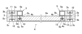
図4は図1(a)の矢印A−A線に沿った断面を示すもので、図示のように、柱3と耐力パネル4との接合に接合部材5を用いる。
ここで、耐力パネル4は芯材4aを含む厚さが、柱3の幅の略半分相当となっている。
なお、耐力パネル4は、矩形枠及びその内方の桟材から構成される芯材4aと、その芯材4aの表面に接合される合板による表面板材とからなり、また、裏面板材を接合したものも用いられる。
FIG. 4 shows a cross section taken along the line AA in FIG. 1A, and as shown in the figure, a joining member 5 is used to join the column 3 and the load bearing panel 4.
Here, the load-bearing panel 4 has a thickness including the core material 4 a that is approximately half the width of the pillar 3.
The load-bearing panel 4 is composed of a core material 4a composed of a rectangular frame and a crosspiece inside thereof, and a front plate material made of plywood bonded to the surface of the core material 4a. Things are also used.

そして、柱3には、厚さ方向の略中央部に挿通溝3aが形成されて、その挿通溝3aと直交して貫通孔3bが形成されている。この貫通孔3bは、柱3の両面に形成した凹部3cにそれぞれ開口している。
また、接合部材5は、柱3の幅の略半分に一面が沿って耐力パネル4の芯材4aに他面側が沿う四角筒による筒部材5aと、その筒部材5aに一体化接合した板部材5bとからなる。その板部材5bは、柱3の挿通溝3aに挿通される挿通片5cを有している。
An insertion groove 3a is formed in the pillar 3 at a substantially central portion in the thickness direction, and a through hole 3b is formed orthogonal to the insertion groove 3a. The through holes 3b open in the recesses 3c formed on both sides of the column 3, respectively.
The joining member 5 is a tubular member 5a made of a rectangular tube whose one surface extends along substantially half the width of the pillar 3 and whose other surface faces the core material 4a of the load-bearing panel 4, and a plate member integrally joined to the tubular member 5a. 5b and. The plate member 5b has an insertion piece 5c that is inserted into the insertion groove 3a of the column 3.

図5は接合部材5の拡大斜視図で、図示のように、挿通片5cの中央に貫通孔5dが形成されて、板部材5bの筒部材5aに重なる部分の中央にボルト5eが一体化接合して備えられている。
実施形態において、接合部材5を構成する筒部材5a及び板部材5bの素材は鋼材である。なお、図示しないが、筒部材5aに代えて、平面視コ字状の折曲鉄板を用い、その両端部を、板部材5bに溶接して実施形態と同様な外形形状の接合部材5を作製してもよい。また、一枚の鉄板を折り曲げて端部を溶接することで実施形態と同様な外形形状の接合部材5を作製してもよい。
FIG. 5 is an enlarged perspective view of the joining member 5. As shown in the drawing, a through hole 5d is formed in the center of the insertion piece 5c, and a bolt 5e is integrally joined to the center of the portion of the plate member 5b overlapping the tubular member 5a. Is prepared for.
In the embodiment, the materials of the tubular member 5a and the plate member 5b that form the joining member 5 are steel materials. Although not shown, a bent iron plate having a U-shape in plan view is used in place of the tubular member 5a, and both ends of the bent iron plate are welded to the plate member 5b to produce the joining member 5 having the same outer shape as that of the embodiment. You may. Alternatively, the joining member 5 having the same outer shape as that of the embodiment may be produced by bending one iron plate and welding the ends.

そして、図4に示すように、耐力パネル4の芯材4aには、ボルト5eを通す貫通孔4bが形成されている。この貫通孔4bは、芯材4aのパネル面側に形成した凹部4cに開口している。 Then, as shown in FIG. 4, a through hole 4b through which the bolt 5e is inserted is formed in the core material 4a of the proof panel 4. The through hole 4b opens into a recess 4c formed on the panel surface side of the core material 4a.

以上の接合部材5は、先ず、図4に示すように、柱3の挿通溝3aに挿通片5cを挿通してから、柱3及び挿通片5cの貫通孔3b・5dに通しボルト11を挿通して、その通しボルト11の両端にナット12をそれぞれ締め付けることで、柱3の幅の略半分に筒部材5aを重ねて固定する。ナット12の締め付けに際しては、凹部3c面に座金を用いる。
こうして、左右の柱3に各々沿って上下に間隔を開けて接合部材5を複数個(図1の例では3個ずつ)それぞれ固定する。
In the joining member 5 described above, first, as shown in FIG. 4, the insertion piece 5c is inserted into the insertion groove 3a of the pillar 3, and then the through bolt 11 is inserted into the through holes 3b and 5d of the pillar 3 and the insertion piece 5c. Then, the nuts 12 are respectively tightened at both ends of the through bolt 11, so that the tubular member 5a is overlapped and fixed to approximately half the width of the column 3. When tightening the nut 12, a washer is used on the surface of the recess 3c.
In this way, a plurality of joining members 5 (each three in the example of FIG. 1) are fixed along the left and right columns 3 with a space vertically provided therebetween.

次に、接合部材5の筒部材5a外側に突出するボルト5eを、耐力パネル4の芯材4aの貫通孔4bに通して、そのボルト5eの先端にナット13を締め付けることで、接合部材5に耐力パネル4を固定する。ナット13の締め付けに際しては、凹部4c面に座金を用いる。
こうして、左右の柱3の各々の接合部材5に耐力パネル4を固定する。
Next, the bolt 5e projecting to the outside of the tubular member 5a of the joining member 5 is passed through the through hole 4b of the core material 4a of the load bearing panel 4, and the nut 13 is tightened at the tip of the bolt 5e. The load bearing panel 4 is fixed. When tightening the nut 13, a washer is used on the surface of the recess 4c.
In this way, the load bearing panel 4 is fixed to the respective joining members 5 of the left and right columns 3.

なお、下梁1及び上梁2にも、同様の挿通溝1a・2a、貫通孔1b・2b、凹部1c・2cが設けられており、下梁1と耐力パネル4との接合、上梁2と耐力パネル4との接合にも、同様の接合部材5を用いて、同様の接合構造により接合する。 The lower beam 1 and the upper beam 2 are also provided with similar insertion grooves 1a and 2a, through holes 1b and 2b, and recesses 1c and 2c. The same joining member 5 is also used to join the proof panel 4 and the yield strength panel 4 with the same joining structure.

また、接合部材5の筒部材5aの内部には、図5に示すように、配線を通す管材8を配管でき、さらに、筒部材5aが管材8の押えを兼ねることもできる。
さらに、筒部材5aは、耐力パネル4に正面から力が加わった際の支持もできる。
Further, as shown in FIG. 5, a pipe member 8 for passing wiring can be piped inside the tubular member 5a of the joining member 5, and the tubular member 5a can also serve as a retainer for the pipe member 8.
Furthermore, the tubular member 5a can also support the load bearing panel 4 when a force is applied from the front.

以上、実施形態によれば、柱3に設けた挿通溝3aに接合部材5の挿通片5cを挿通し、その挿通片5cと柱3に設けた貫通孔3b・5dで通しボルト11及びナット12により結合して柱3と接合部材5を接合する構造なので、接着剤や釘が不要となり、リフォーム時や災害時には、通しボルト11及びナット12を外すだけで柱3と接合部材5を簡単に分解することができる。 As described above, according to the embodiment, the insertion piece 5c of the joining member 5 is inserted into the insertion groove 3a provided in the pillar 3, and the insertion bolt 5c and the through holes 3b and 5d provided in the pillar 3 are used to insert the through bolt 11 and the nut 12. Since the structure in which the pillar 3 and the joining member 5 are joined by joining with each other does not require adhesives or nails, the pillar 3 and the joining member 5 can be easily disassembled simply by removing the through bolt 11 and the nut 12 at the time of reform or disaster. can do.

また、耐力パネル4の芯材4aと接合部材5もボルト5e及びナット13で結合する構造なので、リフォーム時や災害時に、ボルト5e及びナット13を外すだけで耐力パネル4と接合部材5を簡単に分解することができる。 In addition, since the core member 4a of the load bearing panel 4 and the joining member 5 are also joined by the bolts 5e and the nut 13, the bearing panel 4 and the joining member 5 can be easily removed by removing the bolt 5e and the nut 13 at the time of reform or disaster. Can be disassembled.

(実施形態2)
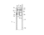
図6は実施形態2として図1(a)の矢印B−B線に沿った断面を示すもので、9は石膏ボードであり、図7はその石膏ボード9側から見た部分正面図である。
(Embodiment 2)
FIG. 6 shows a cross section taken along the line BB in FIG. 1A as Embodiment 2, 9 is a gypsum board, and FIG. 7 is a partial front view seen from the gypsum board 9 side. ..

図示のように、上梁2には、柱3と同様に、厚さ方向の略中央部に挿通溝2aが形成されて、その挿通溝2aと直交して貫通孔2bが形成されている。この貫通孔2bは、上梁2の両面に形成した凹部2cにそれぞれ開口している。 As illustrated, the upper beam 2 has an insertion groove 2a formed in a substantially central portion in the thickness direction, and a through hole 2b is formed orthogonal to the insertion groove 2a, similarly to the pillar 3. The through holes 2b are opened in the recesses 2c formed on both surfaces of the upper beam 2, respectively.

この上梁2の挿通溝2aに挿通片5cを挿通してから、上梁2及び挿通片5cの貫通孔2b・5dに通しボルト11を挿通して、その通しボルト11の両端にナット12をそれぞれ締め付けることで、上梁2に接合部材5を固定する。ナット12の締め付けに際しては、凹部2c面に座金を用いる。
こうして、上梁2に沿って左右に間隔を開けて接合部材5を複数個(図1の例では2個)固定する。
After inserting the insertion piece 5c into the insertion groove 2a of the upper beam 2, the through bolt 11 is inserted into the through holes 2b and 5d of the upper beam 2 and the insertion piece 5c, and the nuts 12 are attached to both ends of the through bolt 11. The joining member 5 is fixed to the upper beam 2 by tightening each. When tightening the nut 12, a washer is used on the surface of the recess 2c.
In this way, a plurality of (two in the example of FIG. 1) joining members 5 are fixed with a space left and right along the upper beam 2.

そして、上梁2の耐力パネル4と反対側面に石膏ボード9が貼り付けられている。この石膏ボード9には、複数個(図7の例では3個)の開口部9aが形成されており、その開口部9aにスイッチ等の機器10がそれぞれ取り付けられている。
この開口部9aは、耐力パネル4の背面側の空間を利用して自由に設けることができ、その開口部9aに各種スイッチやエネルギー関係リモコン、玄関モニタ、給湯器リモコン、地震計、壁付けテレビ等の機器10を取り付けることができる。
なお、開口部9a(機器10)は一つでもよい。
A gypsum board 9 is attached to the side surface of the upper beam 2 opposite to the load bearing panel 4. A plurality of (three in the example of FIG. 7) openings 9a are formed in this gypsum board 9, and devices 10 such as switches are attached to the openings 9a.
This opening 9a can be freely provided by utilizing the space on the back side of the load-bearing panel 4, and various switches, energy-related remote controls, entrance monitors, water heater remote controls, seismographs, wall-mounted televisions can be provided in the openings 9a. Device 10 such as.
The number of openings 9a (device 10) may be one.

(実施形態3)
図8は実施形態3として面材の形状変更例を示す壁部分の正面図で、図示のように、左右の柱3の間に、部分的にパネル14が接合部材5をそれぞれ介して取り付けられていて、パネル14の上下に高窓用開口15と地窓用開口16が形成されている。
図示例では、柱3に凹部3cが等間隔に5個設けられていて、そのうち下から2番目と4番目の凹部3cに対応して接合部材5が柱3にボルト結合してされており、この上下2個の接合部材5にパネル14がボルト結合されている。
(Embodiment 3)
FIG. 8 is a front view of a wall portion showing an example of changing the shape of the face material as the third embodiment, and as shown in the figure, the panels 14 are partially mounted between the left and right columns 3 via the joining members 5, respectively. The high window opening 15 and the ground window opening 16 are formed above and below the panel 14.
In the illustrated example, five recesses 3c are provided in the pillar 3 at equal intervals, and the joining member 5 is bolted to the pillar 3 corresponding to the second and fourth recesses 3c from the bottom. The panel 14 is bolted to the upper and lower two joining members 5.

このように、左右の柱3の間に接合部材5をそれぞれ介して部分的にパネル14を取り付けて、そのパネル14の上下に高窓用開口15と地窓用開口16を形成することで、配線や配管を考慮してパネル14を設置することができる。
そして、将来の移動を考慮して柱3に等間隔に5個の凹部3cを加工しておくことで、部分的なパネル14を上方または下方に移動して設置することができる。
なお、パネル14の上端・下端は適宜延長してもよく、これにより高窓用開口15及び地窓用開口16の上下寸法を調整できる。
In this way, the panel 14 is partially attached between the left and right columns 3 via the joining members 5, and the high window opening 15 and the ground window opening 16 are formed above and below the panel 14, respectively. The panel 14 can be installed in consideration of wiring and piping.
Then, by considering the future movement and processing the five concave portions 3c in the pillar 3 at equal intervals, the partial panel 14 can be moved upward or downward and installed.
Note that the upper and lower ends of the panel 14 may be appropriately extended, whereby the vertical dimensions of the high window opening 15 and the ground window opening 16 can be adjusted.

(変形例1)
図9は変形例1として接合部材5の形状変更例を示すもので、図示のように、板部材5bを略2倍の幅広に形成するとともに、その幅広に対応して柱3に幅広の挿通溝3aを形成して、その挿通溝3aに挿通する幅広の挿通片5cに一対の通しボルト11を通している。
そして、その一対の通しボルト11の端部を、柱3に形成した一対の凹部3cにそれぞれ突出させている。
(Modification 1)
FIG. 9 shows a modified example of the shape of the joining member 5 as a first modification. As shown in the drawing, the plate member 5b is formed to have a width approximately twice as wide, and the pillar 3 is inserted into the pillar 3 in accordance with the width. A groove 3a is formed, and a pair of through bolts 11 are passed through a wide insertion piece 5c that is inserted into the insertion groove 3a.
Then, the ends of the pair of through bolts 11 are made to project into the pair of recesses 3c formed in the pillar 3, respectively.

このように、略2倍の幅広に形成した板部材5bを備える接合部材5を用いてもよい。 As described above, the joining member 5 including the plate member 5b formed to have a width approximately twice as wide may be used.

(変形例2)
図10は変形例2としてボルト結合部の変更例を示すもので、図示のように、接合部材5には、前述した実施形態のボルト5eを設けずに、筒部材5aの板部材5bが重なる内面の中央にナット5fを一体化接合して備える。さらに、ナット5fの孔に対応して筒部材5a及び板部材5bに貫通孔を形成しておく。
(Modification 2)
FIG. 10 shows a modified example of the bolt coupling portion as a modified example 2. As shown in the drawing, the plate member 5b of the tubular member 5a is overlapped with the joining member 5 without providing the bolt 5e of the above-described embodiment. A nut 5f is integrally bonded and provided at the center of the inner surface. Further, through holes are formed in the tubular member 5a and the plate member 5b corresponding to the holes of the nut 5f.

そして、接合部材5の筒部材5aの板部材5bが重なる外面に耐力パネル4の芯材4aを当てて、その芯材4aの凹部4c側において、ボルト17を貫通孔4bから板部材5b及び筒部材5aの貫通孔に挿通してナット5fに締め付けることで、接合部材5に耐力パネル4を固定する。 Then, the core member 4a of the load bearing panel 4 is applied to the outer surface of the joining member 5 on which the plate member 5b of the cylindrical member 5a overlaps, and the bolt 17 is inserted from the through hole 4b to the plate member 5b and the cylinder on the recess 4c side of the core member 4a. The load bearing panel 4 is fixed to the joining member 5 by being inserted into the through hole of the member 5a and tightened to the nut 5f.

このように、接合部材5の筒部材5a内面にナット5fを設けて、芯材4aの凹部4c側からボルト17をナット5fに締め付けて、接合部材5に耐力パネル4を固定してもよい。 In this manner, the nut 5f may be provided on the inner surface of the tubular member 5a of the joining member 5, and the bolt 17 may be fastened to the nut 5f from the recess 4c side of the core member 4a to fix the load bearing panel 4 to the joining member 5.

(変形例3)
図11は変形例3として接合部材5の形状変更例を示すもので、図示のように、接合部材5は、筒部材5aを柱3の全幅に対応する略2倍の幅広に形成して、その筒部材5aの一面側の略中央に設けた挿通片5cと対向する対向面側の略中央に一体化して板部材5gを設けている。
この板部材5gの中央部にナット5hを一体化接合して備える。さらに、ナット5hの孔に対応して板部材5gに貫通孔を形成しておく。
(Modification 3)
FIG. 11 shows a modified example of the shape of the joining member 5 as a modified example 3. As shown in the drawing, the joining member 5 has a tubular member 5 a formed to have a width that is approximately twice as wide as the entire width of the pillar 3. A plate member 5g is provided integrally with the cylindrical member 5a at a substantially central position on a facing surface side facing the insertion piece 5c provided at a central position on one surface side.
A nut 5h is integrally joined and provided to the central portion of the plate member 5g. Further, a through hole is formed in the plate member 5g corresponding to the hole of the nut 5h.

そして、柱3の挿通溝3aに一面側略中央の挿通片5cを挿通して通しボルト11及びナット12で固定して筒部材5aを柱3の全幅に重ねた接合部材5の板部材5gが重なる外面に耐力パネル4の芯材4aを当てて、その芯材4aの凹部4c側において、ボルト17を貫通孔4bから板部材5gの貫通孔に挿通してナット5hに締め付けることで、接合部材5に耐力パネル4を固定する。 Then, the plate member 5g of the joining member 5 in which the insertion member 5c at the one surface side substantially central portion is inserted into the insertion groove 3a of the pillar 3 and fixed by the through bolt 11 and the nut 12 and the tubular member 5a is overlapped with the entire width of the pillar 3 is formed. The core member 4a of the load-bearing panel 4 is applied to the overlapping outer surfaces, and the bolt 17 is inserted from the through hole 4b into the through hole of the plate member 5g and fastened to the nut 5h on the recess 4c side of the core member 4a. The load bearing panel 4 is fixed to 5.

このように、接合部材5の筒部材5aを略2倍の幅広にして柱3の全幅に重ね、その筒部材5aの一面側略中央の挿通片5cと対向する対向面側略中央に突出する板部材5gを設け、その板部材5gにナット5hを設けて、芯材4aの凹部4c側からボルト17をナット5hに締め付けて、接合部材5に耐力パネル4を固定してもよい。 In this way, the tubular member 5a of the joining member 5 is made to have a width that is approximately twice as wide as the entire width of the column 3, and the tubular member 5a is projected to approximately the center on the opposite surface side facing the insertion piece 5c at the one surface side approximately center. The plate member 5g may be provided, the plate member 5g may be provided with a nut 5h, and the bolt 17 may be fastened to the nut 5h from the recess 4c side of the core member 4a to fix the load bearing panel 4 to the joining member 5.

(変形例4)
図12は変形例4として接合部材5の形状変更例及びボルト結合部の変更例を示すもので、図示のように、接合部材5には、前述した実施形態のボルト5eを設けずに、板部材5bの筒部材5aに重なる部分の中央に、他の挿通片5cと板面が直交する第2の挿通片5iを一体化接合して備える。この第2の挿通片5iの中央に図示しない第2の貫通孔を形成する。
また、面材4の両側部に沿った芯材4aに、第2の挿通片5iが挿通される第2の挿通溝4dを形成する。さらに、芯材4aには、第2の挿通溝4dと直交する第2の貫通孔4eを形成するとともに、その第2の貫通孔4eの外端にナット18を埋設しておく。
(Modification 4)
FIG. 12 shows a modification example of the shape of the joining member 5 and a modification example of the bolt coupling portion as Modification Example 4. As illustrated, the joining member 5 is not provided with the bolt 5e of the above-described embodiment, A second insertion piece 5i having a plate surface orthogonal to the other insertion piece 5c is integrally joined and provided at the center of the portion of the member 5b overlapping the tubular member 5a. A second through hole (not shown) is formed in the center of the second insertion piece 5i.
In addition, a second insertion groove 4d into which the second insertion piece 5i is inserted is formed in the core material 4a along both sides of the face material 4. Further, a second through hole 4e orthogonal to the second insertion groove 4d is formed in the core material 4a, and a nut 18 is embedded in the outer end of the second through hole 4e.

そして、芯材4aの第2の挿通溝4dに第2の挿通片5iを挿通してから、芯材4aの内側より第2の貫通孔4eにボルト19を挿通して、ボルト19の先端をナット18に締め付けることで、接合部材5に耐力パネル4をボルト結合する。 Then, after inserting the second insertion piece 5i into the second insertion groove 4d of the core material 4a, the bolt 19 is inserted from the inside of the core material 4a into the second through hole 4e, and the tip of the bolt 19 is inserted. The load bearing panel 4 is bolted to the joining member 5 by tightening the nut 18.

このように、板部材5bの筒部材5aに重なる部分に備えた第2の挿通片5iを、面材4の芯材4aに設けた第2の挿通溝4dに挿通して、第2の挿通片5iと芯材4aとに設けた第2の貫通孔4eで、芯材4aと第2の挿通片5iをボルト結合して、接合部材5に耐力パネル4を固定してもよい。 In this way, the second insertion piece 5i provided in the portion of the plate member 5b overlapping the tubular member 5a is inserted into the second insertion groove 4d provided in the core material 4a of the face material 4, and the second insertion piece 5i is inserted. The strength member panel 4 may be fixed to the joining member 5 by bolting the core material 4a and the second insertion piece 5i with the second through hole 4e provided in the piece 5i and the core material 4a.

(変形例5)
図13は変形例5として接合部材5の形状変更例及びボルト結合部の変更例を示すもので、図示のように、耐力パネル4の芯材4aを含む厚さを柱3の幅の略1/3にして、筒部材5aの外面の中央に挿通片5cを備えて、筒部材5aの挿通片5cと直交する内面の中央にナット5fを一体化接合して備える。さらに、ナット5fの孔に対応して筒部材5aに貫通孔を形成しておく。
(Modification 5)
FIG. 13 shows a modified example of the shape of the joining member 5 and a modified example of the bolt coupling portion as a modified example 5. As shown in the figure, the thickness including the core material 4a of the load bearing panel 4 is approximately 1 of the width of the pillar 3. /3, the insertion member 5c is provided at the center of the outer surface of the tubular member 5a, and the nut 5f is integrally joined and provided at the center of the inner surface orthogonal to the insertion member 5c of the tubular member 5a. Further, a through hole is formed in the tubular member 5a corresponding to the hole of the nut 5f.

そして、柱3の挿通溝3aに一面側略中央の挿通片5cを挿通して通しボルト11及びナット12で固定して筒部材5aを柱3の中央部に重ねた接合部材5の筒部材5aの外面に耐力パネル4の芯材4aを当てて、その芯材4aの凹部4c側において、ボルト17を貫通孔4bから筒部材5aの貫通孔に挿通してナット5fに締め付けることで、接合部材5に耐力パネル4を固定する。 Then, the tubular member 5a of the joining member 5 in which the tubular member 5a is inserted into the through groove 3a of the column 3 and is fixed by the through bolt 11 and the nut 12 by inserting the through piece 5c at the one surface side substantially centrally and the tubular member 5a is overlapped with the central portion of the column 3 The core member 4a of the yield strength panel 4 is applied to the outer surface of the core member 4a, and the bolt 17 is inserted from the through hole 4b into the through hole of the tubular member 5a and fastened to the nut 5f on the recess 4c side of the core member 4a. The load bearing panel 4 is fixed to 5.

このように、耐力パネル4の芯材4aを含む厚さを柱3の幅の略1/3にして、接合部材5の筒部材5aを柱3の中央部に重ね、その筒部材5a内面にナット5fを設けて、筒部材5aを芯材4aに重ね、芯材4aの凹部4c側からボルト17をナット5fに締め付けて、接合部材5に耐力パネル4を固定してもよい。 In this manner, the thickness of the load-bearing panel 4 including the core material 4a is set to about 1/3 of the width of the column 3, and the tubular member 5a of the joining member 5 is superposed on the central portion of the column 3 and is attached to the inner surface of the tubular member 5a. The nut 5f may be provided, the tubular member 5a may be superposed on the core material 4a, and the bolt 17 may be tightened to the nut 5f from the recess 4c side of the core material 4a to fix the load bearing panel 4 to the joining member 5.

(変形例6)
図14は変形例6として柱3の構造変更例を示すもので、図15はその柱3の部分斜視図である。
図示のように、柱3として、厚さ方向の略中央部で二分割された一対の分割部材31と、その一対の分割軸材31の間に接合一体化されて、一様な挿通溝3aの奥方に位置する薄板状の中間部材32とからなる構成とする。
(Modification 6)
FIG. 14 shows a modified example of the structure of the pillar 3, and FIG. 15 is a partial perspective view of the pillar 3.
As shown in the figure, as a pillar 3, a pair of split members 31 that are split into two at a substantially central portion in the thickness direction and a pair of split shaft members 31 are joined and integrated so that a uniform insertion groove 3a is formed. And a thin plate-shaped intermediate member 32 located in the back.

このように、厚さ方向の略中央部で二分割された一対の分割部材31の間に薄板状の中間部材32を接合一体化した柱3として、その薄板状の中間部材32が奥方に位置する一様な挿通溝3aを形成してもよい。 As described above, the thin plate-shaped intermediate member 32 is positioned at the back as the pillar 3 in which the thin plate-shaped intermediate member 32 is joined and integrated between the pair of divided members 31 which are divided into two substantially at the center in the thickness direction. The uniform insertion groove 3a may be formed.

(変形例7)
図16は変形例7として柱3の構造変更例を示すもので、図示のように、柱3として、その厚さ方向の略中央部で二分割された一対の分割部材31と、その一対の分割軸材31の間に接合一体化される薄板状の中間部材33とからなり、その薄板状の中間部材33に複数の挿通溝3aを構成する切欠きを形成されている構成とする。
(Modification 7)
FIG. 16 shows a modification of the structure of the pillar 3 as a modified example 7. As shown in the figure, as the pillar 3, a pair of splitting members 31 split into two at a substantially central portion in the thickness direction, and a pair of splitting members 31. A thin plate-shaped intermediate member 33 joined and integrated between the split shaft members 31 is formed, and the thin plate-shaped intermediate member 33 is formed with notches that form a plurality of insertion grooves 3a.

このように、厚さ方向の略中央部で二分割された一対の分割部材31の間に薄板状の中間部材33を接合一体化した柱3として、その薄板状の中間部材33に複数の挿通溝3aを構成する切欠きを形成してもよい。 As described above, the thin plate-shaped intermediate member 33 is joined and integrated between the pair of divided members 31 which are divided into two at the substantially central portion in the thickness direction, to form a plurality of insertions into the thin plate-shaped intermediate member 33. You may form the notch which comprises the groove|channel 3a.

(他の変形例)
以上の実施形態においては、構造材を軸材(柱及び梁)としたが、本発明はこれに限定されるものではなく、構造材は天井面や床面に設けられるものであってもよい。
また、実施形態では、面材として芯材を有する耐力パネルとしたが、単なるパネルによる面材でもよく、または、積層材でもよく、あるいは、配筋したコンクリートパネルでもよい。
さらに、接合部材の形状等も任意であり、例えば筒部材は、四角筒に限らず、構造材と面材に二面が重なる三角筒でもよく、また、接合部材は鋼材の他、アルミ、樹脂など構造上必要な素材が選択される。
その他、具体的な細部構造等についても適宜に変更可能であることは勿論である。
(Other modifications)
In the above embodiments, the structural member is the shaft member (pillar and beam), but the present invention is not limited to this, and the structural member may be provided on the ceiling surface or the floor surface. ..
Further, in the embodiment, the load bearing panel having the core material as the face material is used, but the face material may be a simple panel, a laminated material, or a reinforced concrete panel.
Further, the shape of the joining member is also arbitrary, and for example, the tubular member is not limited to a square tube, and may be a triangular tube whose two faces overlap the structural material and the face material. Materials that are structurally necessary are selected.
In addition, it goes without saying that the specific detailed structure and the like can be appropriately changed.

1 下梁(構造材、軸材)
1a 挿通溝
1b 貫通孔
1c 凹部
2 上梁(構造材、軸材)
2a 挿通溝
2b 貫通孔
2c 凹部
3 柱(構造材、軸材)
3a 挿通溝
3b 貫通孔
3c 凹部
4 耐力パネル(面材)
4a 芯材
4b 貫通孔
4c 凹部
4d 第2の挿通溝
4e 第2の挿通孔
5 接合部材
5a 筒部材
5b 板部材
5c 挿通片
5d 貫通孔
5e ボルト
5f ナット
5g 板部材
5h ナット
5i 第2の挿通片
6 接合金具
7 接合金具
8 管材
9 石膏ボード
9a 開口部
10 機器
11 通しボルト
12 ナット
13 ナット
14 パネル(面材)
15 高窓用開口
16 地窓用開口
17 ボルト
18 ナット
19 ボルト
31 分割部材
32 中間部材
33 中間部材
1 Lower beam (structural material, shaft material)
1a Insertion groove 1b Through hole 1c Recess 2 Upper beam (structural material, shaft material)
2a Insertion groove 2b Through hole 2c Recess 3 Pillar (structural material, shaft material)
3a Insertion groove 3b Through hole 3c Recess 4 Strength panel (face material)
4a Core material 4b Through hole 4c Recess 4d Second insertion groove 4e Second insertion hole 5 Joining member 5a Tube member 5b Plate member 5c Insertion piece 5d Through hole 5e Bolt 5f Nut 5g Plate member 5h Nut 5i Second insertion piece 6 joining metal fitting 7 joining metal fitting 8 pipe material 9 gypsum board 9a opening 10 equipment 11 through bolt 12 nut 13 nut 14 panel (face material)
15 High Window Opening 16 Ground Window Opening 17 Bolt 18 Nut 19 Bolt 31 Dividing Member 32 Intermediate Member 33 Intermediate Member

Claims (8)

建物の構造材と、その構造材の間に配置される面材とを接合する接合部材を用いる接合構造であって、
前記面材と前記接合部材とがボルト結合されており、
前記構造材は前記接合部材を挿通した挿通溝が設けられており、
前記接合部材の前記挿通溝に挿通した挿通片と前記構造材とにボルトの貫通孔が設けられており、
前記構造材と接合部材とが前記貫通孔に通されたボルトによって結合されており、
前記接合部材は、前記構造材に一面側が沿って前記面材に他面側が沿う筒部材と、その筒部材に一体化して前記挿通片を有する板部材とからなることを特徴とする建物の構造材と面材の接合構造。
A joining structure using a joining member for joining a structural material of a building and a face material arranged between the structural materials,
The face member and the joining member are bolted together,
The structural member is provided with an insertion groove through which the joining member is inserted,
Through holes for bolts are provided in the insertion member and the structural member that are inserted into the insertion groove of the joining member,
The structural member and the joining member are coupled by a bolt passed through the through hole ,
The structure of a building, wherein the joining member includes a tubular member having one surface side along the structural material and the other surface side along the face material, and a plate member having the insertion piece integrated with the tubular member. Bonding structure of material and face material.
建物の構造材と、その構造材の間に配置される面材とを接合する接合部材を用いる接合構造であって、
前記面材と前記接合部材とがボルト結合されており、
前記構造材は前記接合部材を挿通した挿通溝が設けられており、
前記接合部材の前記挿通溝に挿通した挿通片と前記構造材とにボルトの貫通孔が設けられており、
前記構造材と接合部材とが前記貫通孔に通されたボルトによって結合されており、
前記接合部材は、前記構造材に一面側が沿って前記面材に他面側が沿う筒部材と、その筒部材の前記一面側に一体化した前記挿通片と、前記筒部材の前記挿通片側と対向する対向面側に一体化して前記面材に重ねられる板部材とからなることを特徴とする建物の構造材と面材の接合構造。
A joining structure using a joining member for joining a structural material of a building and a face material arranged between the structural materials ,
The face member and the joining member are bolted together ,
The structural member is provided with an insertion groove through which the joining member is inserted,
Through holes for bolts are provided in the insertion member and the structural member that are inserted into the insertion groove of the joining member,
The structural member and the joining member are coupled by a bolt passed through the through hole,
The joining member includes a tubular member having one surface side along the structural member and the other surface side along the face member, the insertion piece integrated with the one surface side of the tubular member, and the insertion piece side of the tubular member facing each other. A joint structure of a building structural material and a face material, which is composed of a plate member that is integrated on the facing surface side and is laminated on the face material.
請求項1または2に記載の建物の構造材と面材の接合構造において、
前記構造材は柱または梁等の軸材で、その軸材には、厚さ方向の略中央部に前記挿通溝が形成されて、その挿通溝と直交して前記貫通孔が形成されていることを特徴とする建物の構造材と面材の接合構造。
In the joint structure of the building structural material and the face material according to claim 1 or 2,
The structural member is a shaft member such as a pillar or a beam, and the insertion groove is formed in the shaft member at a substantially central portion in the thickness direction, and the through hole is formed orthogonal to the insertion groove. This is a joint structure of structural materials and face materials for buildings.
請求項3に記載の建物の構造材と面材の接合構造において、
前記軸材は、前記厚さ方向の略中央部で二分割された一対の分割部材と、その一対の分割軸材の間に接合一体化されて前記挿通溝の奥方に位置する中間部材とからなることを特徴とする建物の構造材と面材の接合構造。
In the joint structure of a building structural material and a face material according to claim 3,
The shaft member is composed of a pair of split members that are split into two at a substantially central portion in the thickness direction, and an intermediate member that is joined and integrated between the pair of split shaft members and is located at the back of the insertion groove. The structure that joins the structural material of the building and the face material.
請求項3に記載の建物の構造材と面材の接合構造において、
前記軸材は、その厚さ方向の略中央部で二分割された一対の分割部材と、その一対の分割軸材の間に接合一体化される中間部材とからなり、
前記中間部材に前記挿通溝を構成する切欠きが形成されていることを特徴とする建物の構造材と面材の接合構造。
In the joint structure of a building structural material and a face material according to claim 3,
The shaft member is composed of a pair of split members that are split into two substantially at the center in the thickness direction, and an intermediate member that is joined and integrated between the pair of split shaft members.
A joint structure of a building structural material and a face material, characterized in that a cutout that forms the insertion groove is formed in the intermediate member.
請求項1又は請求項1を引用する請求項3から5のいずれか一項に記載の建物の構造材と面材の接合構造において、
前記板部材の前記筒部材の前記他面に重なる部分に一体化してボルトを備えることを特徴とする建物の構造材と面材の接合構造。
In the joint structure of the structural material and the face material of the building according to any one of claims 3 to 5 quoting claim 1 or claim 1 ,
A joint structure for a structural material and a face material of a building, comprising a bolt integrated with a portion of the plate member overlapping the other surface of the tubular member .
請求項1又は請求項1を引用する請求項3から5のいずれか一項に記載の建物の構造材と面材の接合構造において、
前記板部材の前記筒部材の前記他面に重なる部分に一体化して第2の挿通片を備え、
前記面材は建築用パネルであって芯材を有し、この芯材に前記第2の挿通片が挿通した第2の挿通溝が設けられており、
前記第2の挿通片と前記芯材とにボルト結合する第2の貫通孔が設けられており、
前記芯材と第2の挿通片を前記第2の貫通孔でボルト結合することを特徴とする建物の構造材と面材の接合構造。
In the joint structure of the structural material and the face material of the building according to any one of claims 3 to 5 quoting claim 1 or claim 1 ,
A second insertion piece that is integrated with a portion of the plate member that overlaps the other surface of the tubular member ,
The face material is a building panel and has a core material, and the core material is provided with a second insertion groove through which the second insertion piece is inserted,
A second through hole for bolting the second insertion piece and the core member is provided,
A joint structure for a structural material and a face material of a building, wherein the core material and a second insertion piece are bolted to each other through the second through hole .
請求項1から5のいずれか一項に記載の建物の構造材と面材の接合構造において、
前記筒部材の一面の略中央に前記挿通片を備えることを特徴とする建物の構造材と面材の接合構造。
In the joint structure of the structural material and face material of the building according to any one of claims 1 to 5 ,
A joint structure for a structural material and a face material of a building , comprising the insertion piece approximately at the center of one surface of the tubular member .
JP2016008167A 2016-01-19 2016-01-19 Bonding structure of building structural material and face material Active JP6739175B2 (en)

Priority Applications (1)

Application Number Priority Date Filing Date Title
JP2016008167A JP6739175B2 (en) 2016-01-19 2016-01-19 Bonding structure of building structural material and face material

Applications Claiming Priority (1)

Application Number Priority Date Filing Date Title
JP2016008167A JP6739175B2 (en) 2016-01-19 2016-01-19 Bonding structure of building structural material and face material

Publications (2)

Publication Number Publication Date
JP2017128894A JP2017128894A (en) 2017-07-27
JP6739175B2 true JP6739175B2 (en) 2020-08-12

Family

ID=59396606

Family Applications (1)

Application Number Title Priority Date Filing Date
JP2016008167A Active JP6739175B2 (en) 2016-01-19 2016-01-19 Bonding structure of building structural material and face material

Country Status (1)

Country Link
JP (1) JP6739175B2 (en)

Families Citing this family (1)

* Cited by examiner, † Cited by third party
Publication number Priority date Publication date Assignee Title
JP7332765B1 (en) 2022-07-22 2023-08-23 ミサワホーム株式会社 bearing wall structure

Also Published As

Publication number Publication date
JP2017128894A (en) 2017-07-27

Similar Documents

Publication Publication Date Title
JP3782817B1 (en) Structural type and construction method of steel house
JP2013514476A (en) Paneled structural system for building
JP2008280787A (en) Joint structure of bearing wall made of lightweight shape steel sheet and foundation
JP2005139623A (en) Reinforcing beam and unit building with the reinforcing beam
WO2006057094A1 (en) Panel structure of steel house and panel construction method
JP6739175B2 (en) Bonding structure of building structural material and face material
JP2009235812A (en) Joint structure of panel used for construction and method, and building structure
JP3209111U (en) Vertical frame material and steel house
JP2001303663A (en) Narrow wall panel structure, portal frame structure and wooden building
KR101409796B1 (en) Unit modular house connection structure using bent column for unit modular house
JP2009057716A (en) Connecting structure of building unit, and fabricated building
JP2018104884A (en) Reinforcing structure and reinforcing method of building
JP5891982B2 (en) Bearing wall joint structure
JP2008156836A (en) Structure of earthquake-resistant wall and earthquake-resistant reinforcement construction method
JP2009030321A (en) Portal frame by connection of composite beam and wooden pillar
JP5445791B2 (en) Panel connection method
JP5004434B2 (en) Steel house
JP5385098B2 (en) Building structural components
JP2020051038A (en) Fixing structure of spandrel wall panel
JP2018115491A (en) Building structure
JP5684648B2 (en) Unit housing
JP2008255713A (en) Wooden building and its seismic reinforcement method
JP2004316296A (en) Multistoried building
JP6949691B2 (en) Post-attached brace joint structure
KR102037979B1 (en) Construction parts for building and method of constructing wall and floor structure using the same

Legal Events

Date Code Title Description
A621 Written request for application examination

Free format text: JAPANESE INTERMEDIATE CODE: A621

Effective date: 20190115

A977 Report on retrieval

Free format text: JAPANESE INTERMEDIATE CODE: A971007

Effective date: 20191011

A131 Notification of reasons for refusal

Free format text: JAPANESE INTERMEDIATE CODE: A131

Effective date: 20191126

A521 Written amendment

Free format text: JAPANESE INTERMEDIATE CODE: A523

Effective date: 20200121

TRDD Decision of grant or rejection written
A01 Written decision to grant a patent or to grant a registration (utility model)

Free format text: JAPANESE INTERMEDIATE CODE: A01

Effective date: 20200714

A61 First payment of annual fees (during grant procedure)

Free format text: JAPANESE INTERMEDIATE CODE: A61

Effective date: 20200721

R150 Certificate of patent or registration of utility model

Ref document number: 6739175

Country of ref document: JP

Free format text: JAPANESE INTERMEDIATE CODE: R150