JP5663192B2 - Processing apparatus, coordinate correction method, and coordinate correction program - Google Patents
Processing apparatus, coordinate correction method, and coordinate correction program Download PDFInfo
- Publication number
- JP5663192B2 JP5663192B2 JP2010105475A JP2010105475A JP5663192B2 JP 5663192 B2 JP5663192 B2 JP 5663192B2 JP 2010105475 A JP2010105475 A JP 2010105475A JP 2010105475 A JP2010105475 A JP 2010105475A JP 5663192 B2 JP5663192 B2 JP 5663192B2
- Authority
- JP
- Japan
- Prior art keywords
- measurement
- inspection
- coordinates
- substrate
- unit
- Prior art date
- Legal status (The legal status is an assumption and is not a legal conclusion. Google has not performed a legal analysis and makes no representation as to the accuracy of the status listed.)
- Expired - Fee Related
Links
Images


Classifications
-
- G—PHYSICS
- G01—MEASURING; TESTING
- G01B—MEASURING LENGTH, THICKNESS OR SIMILAR LINEAR DIMENSIONS; MEASURING ANGLES; MEASURING AREAS; MEASURING IRREGULARITIES OF SURFACES OR CONTOURS
- G01B5/00—Measuring arrangements characterised by the use of mechanical techniques
- G01B5/004—Measuring arrangements characterised by the use of mechanical techniques for measuring coordinates of points
-
- H—ELECTRICITY
- H01—ELECTRIC ELEMENTS
- H01L—SEMICONDUCTOR DEVICES NOT COVERED BY CLASS H10
- H01L21/00—Processes or apparatus adapted for the manufacture or treatment of semiconductor or solid state devices or of parts thereof
- H01L21/67—Apparatus specially adapted for handling semiconductor or electric solid state devices during manufacture or treatment thereof; Apparatus specially adapted for handling wafers during manufacture or treatment of semiconductor or electric solid state devices or components ; Apparatus not specifically provided for elsewhere
- H01L21/67005—Apparatus not specifically provided for elsewhere
- H01L21/67242—Apparatus for monitoring, sorting or marking
- H01L21/67259—Position monitoring, e.g. misposition detection or presence detection
-
- H—ELECTRICITY
- H05—ELECTRIC TECHNIQUES NOT OTHERWISE PROVIDED FOR
- H05K—PRINTED CIRCUITS; CASINGS OR CONSTRUCTIONAL DETAILS OF ELECTRIC APPARATUS; MANUFACTURE OF ASSEMBLAGES OF ELECTRICAL COMPONENTS
- H05K13/00—Apparatus or processes specially adapted for manufacturing or adjusting assemblages of electric components
- H05K13/0015—Orientation; Alignment; Positioning
Description
本発明は、処理装置、処理システム、座標補正方法および座標補正プログラムに関する。 The present invention relates to a processing device, a processing system, a coordinate correction method, and a coordinate correction program.
従来、たとえばガラス基板などの広い処理対象面を持つ基板に対して検査や測定などの処理を行う処理装置では、処理対象面の特定位置を検査/測定する際、レシピに登録された座標に基づいて、基板が載置されるステージや検査/測定ユニットを移動する。ただし、レシピに登録された対象パターンの座標と、ステージ上の実際の対象パターンの座標とは、必ずしも一致するものではない。そこで、例えば以下に示す特許文献1では、基板が載置された検査ステージのステージ原点からの移動量に応じた移動補正量を基板移動の際のレシピに記憶しておき、同一品種の基板については、指定された座標データに対して移動補正量を加えた座標データに従って基板を移動していた。 Conventionally, in a processing apparatus that performs processing such as inspection or measurement on a substrate having a wide processing target surface such as a glass substrate, when inspecting / measuring a specific position of the processing target surface, it is based on the coordinates registered in the recipe. The stage on which the substrate is placed and the inspection / measurement unit are moved. However, the coordinates of the target pattern registered in the recipe do not necessarily match the coordinates of the actual target pattern on the stage. Therefore, for example, in Patent Document 1 shown below, a movement correction amount corresponding to the movement amount of the inspection stage on which the substrate is placed from the stage origin is stored in a recipe for moving the substrate, and the same type of substrate is stored. Moved the substrate according to coordinate data obtained by adding a movement correction amount to the designated coordinate data.
しかしながら、上記従来の技術では、レシピに登録された対象パターンの座標が実際の対象パターンの座標からずれていた場合、手動により実際の座標を特定して移動補正量を求める必要があった。このため、従来の技術では、処理工程の増大と煩雑化とが生じ易く、処理装置でのスループットが低下し易いという問題があった。 However, in the above conventional technique, when the coordinates of the target pattern registered in the recipe deviate from the coordinates of the actual target pattern, it is necessary to manually specify the actual coordinates and obtain the movement correction amount. For this reason, in the conventional technology, there is a problem that the processing process is easily increased and complicated, and the throughput in the processing apparatus is likely to be reduced.
そこで本発明は、上記の問題に鑑みてなされたものであり、スループットの低下を低減しつつ、レシピに登録された座標と実際の座標とのずれを自動的に補正することが可能な処理装置、処理システム、座標補正方法および座標補正プログラムを提供することを目的とする。 Therefore, the present invention has been made in view of the above problems, and is a processing device capable of automatically correcting a deviation between coordinates registered in a recipe and actual coordinates while reducing a decrease in throughput. An object of the present invention is to provide a processing system, a coordinate correction method, and a coordinate correction program.
かかる目的を達成するために、本発明の一実施態様の処理装置は、基板上の検査・測定対象の位置を示す検査・測定座標を登録したレシピに基づいて前記基板における前記検査・測定対象に所定の処理を実行する処理装置であって、前記基板を撮像する撮像手段を有し、該撮像手段が撮像した画像に基づいて前記検査・測定対象の検査・測定する検査・測定ユニットと、選択中の検査・測定座標に前記検査・測定ユニットを移動させる移動手段と、前記選択中の検査・測定座標に前記検査・測定ユニットを位置した状態で前記撮像手段により撮像された画像から前記選択中の検査・測定座標に対応する対象モデルを検索する検索処理手段と、前記検索処理手段によって検索した結果に基づいて、前記対象モデルが検査測定領域に位置するように前記検査・測定ユニットを移動させる引きこみ処理手段と、前記引きこみ処理手段によって引き込まれた後の前記対象モデルの実座標を前記選択中の検査・測定座標としてレシピに登録する実座標登録手段と、を備えたことを特徴とする。 To achieve the above object, the processing apparatus of one embodiment of the present invention, the inspection and measurement object in front Symbol substrate based on a recipe that registered the inspection and measurement coordinates for indicating the checking and position of the measurement object on a substrate A processing apparatus for performing predetermined processing, and having an imaging unit for imaging the substrate, and an inspection / measurement unit for inspecting / measuring the inspection / measurement object based on an image captured by the imaging unit; The moving means for moving the inspection / measurement unit to the selected inspection / measurement coordinates, and the selection from the image picked up by the imaging means in a state where the inspection / measurement unit is located at the selected inspection / measurement coordinates and search processing means for searching the object model corresponding to the check and measurement coordinates in, based on the result of a search by said search processing means, so that the object model is positioned in the inspection measurement region A pull-processing means for moving the test and measurement unit, a real coordinate registration means for registering a recipe real coordinates of the object model I drawn by the pull-processing means as a test and measurement coordinates in the selection , characterized by comprising a.
また、本発明の一実施態様の座標補正方法は、基板における検査・測定対象に所定の処理を実行する際に使用するレシピに登録された前記検査・測定対象の前記基板上の座標を補正する座標補正方法であって、前記基板を撮像する撮像手段を有し、該撮像手段が撮像した画像に基づいて前記検査・測定対象の検査・測定する検査・測定ユニットを選択中の検査・測定座標に移動させるステップと、前記選択中の検査・測定座標に前記検査・測定ユニットを移動した位置で前記撮像手段により画像を撮像するステップと、前記撮像手段により撮像された画像から前記選択中の検査・測定座標に対応する対象モデルを検索するステップと、検索した結果に基づいて、前記対象モデルが検査測定領域に位置するように前記検査・測定ユニットを移動するステップと、前記対象モデルが検査測定領域に位置したときの前記対象モデルの実座標を前記選択中の検査・測定座標としてレシピに登録するステップと、を含むことを特徴とする。 The coordinate correcting method of an embodiment of the present invention, it corrects the coordinates of the upper substrate of the test and measurement subjects enrolled in the recipe to be used when executing the predetermined processing to the inspection and measurement object in board A coordinate correction method comprising: an imaging unit that images the substrate; and an inspection / measurement unit that selects an inspection / measurement unit that inspects / measures the inspection / measurement object based on an image captured by the imaging unit A step of moving to the coordinates; a step of capturing an image by the imaging unit at a position where the inspection / measurement unit is moved to the selected inspection / measurement coordinate; and a step of selecting from the image captured by the imaging unit moving retrieving an object model corresponding to the test and measurement coordinates, based on a result of the search, the test and measurement unit such that the target model is positioned in the inspection measurement region A step that the object model, characterized in that it comprises the steps of: a real coordinate of the object model is registered in a recipe as an inspection and measurement coordinates in the selection when located in the inspection measurement region.
また、本発明の一実施態様の座標更新プログラムは、基板における検査・測定対象に所定の処理を実行する際に使用するレシピに登録された前記検査・測定対象の前記基板上の座標を補正する処理をコンピュータに実行させるための座標補正プログラムであって、前記基板を撮像する撮像手段を有し、該撮像手段が撮像した画像に基づいて前記検査・測定対象の検査・測定する検査・測定ユニットを選択中の検査・測定座標に移動させる処理と、前記選択中の検査・測定座標に前記検査・測定ユニットを移動した位置で前記撮像手段により画像を撮像する処理と、前記撮像手段により撮像された画像から前記選択中の検査・測定座標に対応する対象モデルを検索する処理と、検索した結果に基づいて、前記対象モデルが検査測定領域に位置するように前記検査・測定ユニットを移動する処理と、前記対象モデルが検査測定領域に位置したときの前記対象モデルの実座標を前記選択中の検査・測定座標としてレシピに登録する処理と、を前記コンピュータに実行させる。 The coordinate update an embodiment of the present invention, it corrects the coordinates of the upper substrate of the test and measurement subjects enrolled in the recipe to be used when executing the predetermined processing to the inspection and measurement object in board A coordinate correction program for causing a computer to execute processing to be performed, comprising: an imaging unit that images the substrate; and an inspection / measurement that inspects / measures the inspection / measurement object based on an image captured by the imaging unit A process of moving the unit to the selected inspection / measurement coordinate, a process of capturing an image by the imaging unit at a position where the inspection / measurement unit has been moved to the selected inspection / measurement coordinate, and an imaging by the imaging unit a process of searching an object model corresponding to the test and measurement coordinates in the selection from an image, based on a result of the search, the object model to position the inspection measurement region Wherein the process of moving the test and measurement unit, and a process of registering a recipe as an inspection and measurement coordinates in said selected real coordinates of the object model when the object model is positioned in the inspection measurement region as Let the computer run.
本発明によれば、ステージ上に載置された基板における処理対象の実際の座標を特定してこの実際の座標をレシピに登録するため、スループットの低下を低減しつつ、レシピに登録された座標と実際の座標とのずれを自動的に補正することが可能な処理装置、処理システム、座標補正方法および座標補正プログラムを実現することができる。 According to the present invention, since the actual coordinates of the processing target on the substrate placed on the stage are specified and the actual coordinates are registered in the recipe, the coordinates registered in the recipe are reduced while reducing a decrease in throughput. It is possible to realize a processing device, a processing system, a coordinate correction method, and a coordinate correction program that can automatically correct a deviation between the actual coordinate and the actual coordinate.
以下、本発明を実施するための形態を図面と共に詳細に説明する。なお、以下の説明において、各図は本発明の内容を理解でき得る程度に形状、大きさ、および位置関係を概略的に示してあるに過ぎず、従って、本発明は各図で例示された形状、大きさ、および位置関係のみに限定されるものではない。また、後述において例示する数値は、本発明の好適な例に過ぎず、従って、本発明は例示された数値に限定されるものではない。 DESCRIPTION OF EMBODIMENTS Hereinafter, embodiments for carrying out the present invention will be described in detail with reference to the drawings. In the following description, each drawing only schematically shows the shape, size, and positional relationship to the extent that the contents of the present invention can be understood. Therefore, the present invention is illustrated in each drawing. It is not limited to only the shape, size, and positional relationship. Moreover, the numerical value illustrated below is only a suitable example of this invention, Therefore, this invention is not limited to the illustrated numerical value.
(一実施の形態)
まず、本発明の一実施の形態による処理装置、処理システム、座標補正方法および座標補正プログラムを、図面を参照して詳細に説明する。なお、以下の説明では、処理装置として、ガラス基板などの基板を検査・測定する基板検査・測定装置を例に挙げる。ただし、これに限定されず、たとえば基板における欠陥箇所をレーザ照射等によって修復する、いわゆるリペア装置など、基板に対する処理を実行する各種処理装置を適用することができる。
(One embodiment)
First, a processing device, a processing system, a coordinate correction method, and a coordinate correction program according to an embodiment of the present invention will be described in detail with reference to the drawings. In the following description, a substrate inspection / measurement apparatus for inspecting / measuring a substrate such as a glass substrate is taken as an example of the processing apparatus. However, the present invention is not limited to this, and various processing apparatuses that perform processing on the substrate, such as a so-called repair device that repairs a defective portion on the substrate by laser irradiation or the like, can be applied.
図1は、本実施の形態による基板検査・測定システムの概略構成を示す模式図である。図1に示すように、基板検査・測定システムは、1つ以上の基板検査・測定装置10A、10B、…(以下、区別する必要が無い際の基板検査・測定装置の符号を10とする)と、基板検査・測定装置10A、10B、…へ基板を搬入出する基板搬入出部15A、15B、…(以下、区別する必要が無い際の基板検査・測定装置の符号を15とする)と、1つ以上の基板検査・測定装置10および1つ以上の基板搬入出部15が接続されたネットワーク110と、ネットワーク110に接続されたホストコンピュータ(PC)100と、を備える。なお、ネットワーク110には、ローカルエリアネットワーク(LAN)やインターネットや専用回線など、種々のネットワークを適用することができる。
FIG. 1 is a schematic diagram showing a schematic configuration of a substrate inspection / measurement system according to the present embodiment. As shown in FIG. 1, the substrate inspection / measurement system includes one or more substrate inspection /
個々の基板検査・測定装置10は、検査・測定対象の基板を搬送する搬送ステージ13と、搬送ステージ13を制御するステージコントローラ12と、搬送ステージ13上の基板を特定位置で検査・測定する検査・測定ユニット14と、ステージコントローラ12および検査・測定ユニット14を制御する制御コンピュータ(PC)11と、を備える。制御PC11は、検査・測定ユニット14で取得された検査・測定結果(たとえば画像)を処理する処理部11bと、画像データやレシピや各種プログラムおよびパラメータ等を記憶する記憶部11cと、他の基板検査・測定装置10や基板搬入出部15やホストPC100との通信を担う通信部11dと、制御PC11内の各部の動作や各種処理を実行する制御部11aと、を備える。
Each substrate inspection /
レシピには、基板に対する検査・測定対象(モデル)の位置を示す座標(以下、検査・測定座標という)や、レシピ登録時の撮像における光量および倍率などの情報が、検査・測定時のパラメータとして登録される。このレシピは、たとえばホストPC100または他の基板検査・測定装置10からネットワーク110を介して各基板検査・測定装置10に送信される。すなわち、レシピは、複数の基板検査・測定装置10において共有される。各基板検査・測定装置10は、受信した、または、取得したレシピを記憶部11c内に保持しておき、必要に応じて読み出す。
The recipe includes coordinates indicating the position of the inspection / measurement target (model) with respect to the substrate (hereinafter referred to as inspection / measurement coordinates) and information such as the amount of light and magnification during imaging when the recipe is registered as parameters for inspection / measurement. be registered. This recipe is transmitted from the
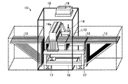
ここで、基板検査・測定装置10の概略構成を、図面を用いて詳細に説明する。図2は、本実施の形態による基板検査・測定装置の概略構成を示す外観図である。図2に示すように、基板検査・測定装置10では、搬送ステージ13が架台16に固定されている。架台16は、たとえばスチール材を組み合わせたフレームなどで構成することができる。ただし、ブロック状の大理石などを用いてもよい。また、架台16には、たとえば顕微鏡などの検査・測定ユニット14を検査・測定ラインL13に沿って移動可能に保持するガントリーステージ14aが固定される。架台16と設置面(たとえば床)との間には、たとえばスプリングや油圧ダンパなどで構成された振動吸収機構17が設けられてもよい。この構成により、搬送ステージ13および検査・測定ユニット14の振動を抑制することが可能になる。このような基板検査・測定装置10は、たとえば外装18およびファンフィルタユニット(FFU)19によって形成されるクリーンルーム内に収容される。
Here, a schematic configuration of the substrate inspection /
つづいて、搬送ステージ13上の基板Wと検査・測定ユニット14との関係を、図面を用いて詳細に説明する。図3は、本実施の形態における搬送ステージ上の基板と検査・測定ユニットとの関係を示す概略模式図である。ただし、図3では、搬送ステージ13を簡素化して示す。
Next, the relationship between the substrate W on the
図3に示すように、搬送ステージ13上の基板Wは、搬入出方向D1に沿って搬送ステージ13上を移動する。搬送ステージ13の上面には、たとえば無数の穴が設けられている。この穴から空気を吹き出すことで、搬送ステージ13上の基板Wを搬送ステージ13に直接接触させることなく移動させることが可能となる(浮上搬送)。搬送ステージ13上での基板Wの移動は、制御PC11からの制御の下で動作するステージコントローラ12によって制御される。たとえば、ステージコントローラ12は、搬送ステージ13の脇に隣接して配置され、制御PC11からの制御の下で搬入出方向D1へ移動する移送ユニット(不図示)を含む。基板Wは、たとえば端部もしくは中央部(重心位置)などの少なくとも1箇所が移送ユニットに担持されることで、制御PC11からの制御に従って搬送ステージ13上を搬入出方向D1に沿って移動する。また、この他にも、搬送ステージ13の上面に複数の駆動ローラまたはフリーローラを設け、このローラによって搬送ステージ13上の基板Wを搬送ステージ13に直接接触させることなく移動するように構成することもできる。
As shown in FIG. 3, the substrate W on the
一方、検査・測定ユニット14は、長手方向D2が搬入出方向D1に対して垂直となるように配置されたガントリーステージ14aの長手方向D2に沿って移動しつつ、搬送ステージ13上の基板Wを検査・測定する。したがって、検査・測定ユニット14は、検査・測定ラインL13上のある位置において基板Wを検査・測定する。検査・測定ユニット14の移動は、ガントリーステージ14aに実装されたリニアモータ駆動機構、または、検査・測定ユニット14に実装された自走機構によって実現される。リニアモータ駆動機構または自走機構の駆動は、制御PC11によって制御される。なお、ガントリーステージ14a自体が、基板Wに対して搬入出方向D1および/または長手方向D2に移動するように構成しても良い。この場合、ガントリーステージ14aを移動させるリニアモータ駆動機構または自走機構などの移動機構は、制御PC11によって制御される。
On the other hand, the inspection /
ここで、レシピに登録され得る検査・測定座標には、基板設計情報に基づいた座標(以下、設計座標という)と、基板W上の実際の座標(以下、実座標という)と、の少なくとも2種類が存在する。設計座標は、基板Wにおける設計上のある位置(たとえばアライメントマーク位置)を原点とした設計段階での座標である。一方、実座標は、実際の基板Wのある位置(たとえばアライメントマーク位置)を原点として測定された座標である。ただし、実座標を直接含める代わりに、設計座標に対する実座標のずれ量(たとえば後述するモデル引き込み処理や周辺サーチ処理における基板および検査・測定ユニット14の移動量、または、設計座標と実座標との差等)を補正量としてレシピに登録しておくことで、実質上、実座標を登録した場合と同様の構成を得ることもできる。
Here, the inspection / measurement coordinates that can be registered in the recipe include at least two of coordinates based on the board design information (hereinafter referred to as design coordinates) and actual coordinates on the substrate W (hereinafter referred to as real coordinates). There are types. The design coordinates are coordinates at the design stage with a design position on the substrate W (for example, an alignment mark position) as the origin. On the other hand, the actual coordinates are coordinates measured using a position (for example, an alignment mark position) of the actual substrate W as an origin. However, instead of including the actual coordinates directly, the deviation amount of the actual coordinates with respect to the design coordinates (for example, the movement amount of the substrate and the inspection /
つぎに、本実施の形態による基板検査・測定装置10の動作について、図面を用いて詳細に説明する。本実施の形態による動作には、レシピを作成する動作(レシピ作成動作)と、レシピを用いて基板を検査・測定する動作(検査・測定動作)と、が含まれる。
Next, the operation of the substrate inspection /
図4は、本実施の形態による基板検査・測定装置のレシピ作成動作の概略を示すフローチャートである。なお、レシピ作成動作において作成されるレシピには、検査・測定対象(モデル)の基板上の位置を示す座標(設計座標)が検査・測定座標としてあらかじめ登録されているものとする。以下の説明では、基板検査・測定装置10の制御PC11における制御部11aの動作に着目する。
FIG. 4 is a flowchart showing an outline of the recipe creation operation of the board inspection / measurement apparatus according to this embodiment. In the recipe created in the recipe creation operation, coordinates (design coordinates) indicating the position of the inspection / measurement target (model) on the substrate are registered in advance as inspection / measurement coordinates. In the following description, attention is paid to the operation of the control unit 11a in the
図4に示すように、本実施の形態によるレシピ作成動作では、制御部11aは、まず、たとえば外部のコンピュータ等から入力された基板設計情報に基づいて、検査・測定対象とするモデルの設計上の座標を検査・測定座標(設計座標)としてレシピに登録する(ステップS101)。なお、この検査・測定座標(設計座標)の登録は、自動登録であっても、ユーザの作業による手動登録であってもよい。また、レシピは、あらかじめ作成しておいたファイル(空ファイルを含む)であっても、このステップで新たに作成されたファイルであってもよい。 As shown in FIG. 4, in the recipe creation operation according to the present embodiment, the control unit 11a first designs a model to be inspected / measured based on, for example, board design information input from an external computer or the like. Are registered in the recipe as inspection / measurement coordinates (design coordinates) (step S101). The inspection / measurement coordinates (design coordinates) may be registered automatically or manually by a user. The recipe may be a file created in advance (including an empty file) or a file newly created in this step.
つぎに、制御部11aは、ホストPC100からの指示に従って基板搬入出部15から基板Wを搬送ステージ13上に搬入し(ステップS102)、この搬入された基板Wを機械的に位置決め(基板アライメント)する(ステップS103)。これにより、ステージコントローラ12の移送ユニットに対する基板Wの位置が粗調整される。つぎに、制御部11aは、検査・測定ユニット14の光量および倍率を、基板Wの搬送ステージ13に対する位置ずれを補正するアライメント補正をする際の光量および倍率に切り換え(ステップS104)、つづいて、ステージコントローラ12を駆動することで基板Wを搬送ステージ13上の所定位置(アライメントマーク位置)に移動する(ステップS105)。つづいて、制御部11aは、ステージコントローラ12および検査・測定ユニット14を適宜駆動することで、基板Wに形成されたアライメントマークを測定し、この測定により得られたアライメントマークの位置から、移動後に基板Wがあるべき位置に対する基板Wの実際の位置のずれ量を算出し、このずれ量に基づいて、基板Wに対する座標系を補正(アライメント補正)する(ステップS106)。
Next, the control unit 11a loads the substrate W from the substrate loading / unloading unit 15 onto the
基板Wの座標系のずれは、基板Wを載置する際の位置決め精度や、ステージコントローラ12による移動の精度や、製造過程において基板W自体に生じた設計寸法に対するずれや、基板検査・測定装置10自体が持つ歪み(X−Y軸の直交性、回転度、各軸の伸縮、ピッチング、ヨーイングなど)等によって生じる。したがって、ステップS106のアライメント補正では、制御PC11による制御における座標系に対する、搬送ステージ13上に載置された基板W自体の座標系のずれが補正される。具体的な例を、図5に示す例を用いて説明する。図5は、本実施の形態によるアライメント補正を説明するための概略図である。図5に示す例では、基板Wの対角に位置する隅付近の所定位置に2つのアライメントマーク(M1、M2)が形成されている。たとえば移動後に基板Wがあるべき位置に存在する場合の基板を基板Wiとし、移動後の実際の基板Wを基板Wrとすると、制御部11aは、基板WiのアライメントマークM1iに対する基板WrのアライメントマークM1rのずれ量(Δx1,Δy1)を算出するとともに、基板WiのアライメントマークM2iに対する基板WrのアライメントマークM2rのずれ量(Δx2,Δy2)を算出する。つづいて、制御部11aは、各アライメントマーク(M1、M2)のずれ量(Δx1,Δy1)および(Δx2,Δy2)から、実際の基板Wrの理想的な位置(基板Wiの位置)に対するx方向のずれ量(Δx)とy方向のずれ量(Δy)と回転量(θ)とを算出し、この値(Δx,Δy,θ)に基づいて、実際の基板Wrの座標系を補正する。これにより、アライメントエラーによってオフセットとして生じる基板W自体の位置ずれを補正することが可能となる。なお、ステップS105の移動によっても検査・測定ユニット14によってアライメントマークを撮像できなかった場合、後述する周辺サーチ処理(図7参照)を行うことによって、アライメントマークを検索するようにしてもよい。
The deviation of the coordinate system of the substrate W includes the positioning accuracy when placing the substrate W, the accuracy of movement by the
図4に戻り説明する。以上のように基板Wの座標系を補正すると、つぎに制御部11aは、ユーザがレシピに登録された検査・測定座標を自動で補正する指示を不図示の入力部を介して入力したか否かを判定し(ステップS107)、入力されていない場合(ステップS107のNo)、そのまま本動作を終了する。一方、自動補正の指示が入力されていた場合(ステップS107のYes)、制御部11aは、検査・測定ユニット14の光量および倍率を検査・測定時の光量および倍率に切り換える(ステップS108)。つづいて、制御部11aは、レシピに登録された検査・測定座標(設計座標)のうち1つを選択し(ステップS109)、つづいて、ステージコントローラ12および検査・測定ユニット14を駆動することで、検査・測定領域のたとえば中央に、選択した検査・測定座標(設計座標)を移動させる(ステップS110)。
Returning to FIG. When the coordinate system of the substrate W is corrected as described above, the control unit 11a next determines whether or not the user has input an instruction to automatically correct the inspection / measurement coordinates registered in the recipe via an input unit (not shown). This is determined (step S107), and if it is not input (No in step S107), this operation is terminated as it is. On the other hand, if an instruction for automatic correction has been input (Yes in step S107), the control unit 11a switches the light amount and magnification of the inspection /
つぎに、制御部11aは、検査・測定対象のパターン(モデル)を検索するモデル検索処理を実行する(ステップS111)。図6に、このモデル検索処理の具体例を示す。図6に示すように、モデル検索処理では、制御部11aは、まず、検査・測定ユニット14を駆動して基板Wの検査・測定領域を撮像する(ステップS201)。この際、検査・測定ユニット14は、たとえば検査・測定時の光量および倍率と同じ光量および倍率で基板Wを測定する。つづいて、制御部11aは、ステップS201で得られた画像を処理部11bによって解析することで、この画像にモデルのパターンが含まれているか否かを検索する(ステップS202)。ステップS202のパターン検索の結果、画像に対象モデルのパターンが含まれている場合(ステップS203のYes)、制御部11aは、図4に示す動作へリターンする。一方、画像に対象モデルのパターンが含まれていない場合(ステップS203のNo)、制御部11aは、選択中の検査・測定座標を含む検査・測定領域に隣接する周辺領域をモデル検索する周辺サーチ処理を実行する(ステップS204)。
Next, the controller 11a executes a model search process for searching for a pattern (model) to be inspected / measured (step S111). FIG. 6 shows a specific example of this model search process. As shown in FIG. 6, in the model search process, the control unit 11a first drives the inspection /
ここで、図7に、この周辺サーチ処理の具体例を示す。図7に示すように、周辺サーチ処理では、制御部11aは、まず、選択中の検査・測定座標を含む検査・測定領域を取り囲むように隣接するたとえば8つの周辺領域のうち、あらかじめ定められた順序に従っていずれか1つを選択し、この選択した領域が映されるように、ステージコントローラ12および検査・測定ユニット14を駆動して、選択した周辺領域へ移動する(ステップS301)。つぎに、制御部11aは、検査・測定ユニット14を駆動して基板Wの現在の検査・測定領域を撮像する(ステップS302)。この際、検査・測定ユニット14は、たとえば検査・測定時の光量および倍率と同じ光量および倍率で基板Wを測定する。つづいて、制御部11aは、ステップS302で得られた画像を処理部11bによって解析することで、この画像にモデルのパターンが含まれているか否かを検索する(ステップS303)。ステップS303のパターン検索の結果、画像に対象モデルのパターンが含まれている場合(ステップS304のYes)、制御部11aは、図6に示す動作へリターンする。一方、画像に対象モデルのパターンが含まれていない場合(ステップS304のNo)、制御部11aは、全ての周辺領域を検索済みであるか否かを判定し(ステップS305)、検索済みでない場合(ステップS305のNo)、ステップS301へ帰還して、あらかじめ定められた順序に従って次の周辺領域を選択する。一方、全ての周辺領域を検索済みである場合(ステップS305のYes)、制御部11aは、図6に示す動作へリターンする。
FIG. 7 shows a specific example of the peripheral search process. As shown in FIG. 7, in the peripheral search process, the control unit 11a first determines a predetermined one of, for example, eight peripheral areas adjacent to surround the inspection / measurement area including the selected inspection / measurement coordinate. According to the order, any one is selected, and the
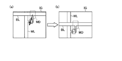
図6に戻り説明する。以上のようにして、選択中の検査・測定座標に対応するモデルを特定すると、制御部11aは、図4に示す動作へリターンする。つづいて、図4に戻り説明する。ステップS111においてモデル検索処理を完了すると、つぎに制御部11aは、検査・測定領域内に映し出されたモデルを、この検査・測定領域の中央に引き込むモデル引き込み処理を実行する(ステップS112)。具体的には、たとえば図8に示す例のように、制御部11aは、画像に含まれる特定のモデルMDが(図8(a)参照)、検査・測定領域IGの中央に位置するように(図8(b)参照)、ステージコントローラ12および検査・測定ユニット14を駆動する。なお、図8は、本実施の形態におけるモデル引き込み処理を説明するための図である。図8において、BLは、たとえば基板Wに形成されたビットラインであり、WLは、たとえば基板Wに形成されたワードラインである。したがって、この例では、ビットラインBLとワードラインWLとを接続するノード部分のパターンを検査・測定対象のモデルとしている。
Returning to FIG. When the model corresponding to the selected inspection / measurement coordinate is specified as described above, the control unit 11a returns to the operation shown in FIG. Next, returning to FIG. When the model search process is completed in step S111, the control unit 11a then executes a model pull-in process for drawing the model displayed in the inspection / measurement area into the center of the inspection / measurement area (step S112). Specifically, as in the example illustrated in FIG. 8, for example, the control unit 11 a causes the specific model MD included in the image (see FIG. 8A) to be positioned at the center of the inspection / measurement region IG. The
図4に戻り説明する。図8を用いて説明したように、対象モデルを検査・測定領域IGの中央に引き込むと、つぎに制御部11aは、引き込み後に検査・測定ユニット14によって撮像された画像を処理部11bで解析することで、画像におけるパターンの線幅やオーバレイを測定する(ステップS113)とともに、引き込み後のモデルの実座標を特定し、この実座標を検査・測定座標としてレシピに登録する(ステップS114:実座標特定手段/ステップ/処理、実座標登録手段/ステップ/処理)。すなわち、図1における制御部11aは、引き込み後のモデルの実座標を特定し、この実座標を検査・測定座標としてレシピに登録する実座標特定手段、ならびに実座標登録手段として機能する。この際、解析により得られた線幅やオーバレイも併せてレシピに登録してもよい。つづいて、制御部11aは、レシピに登録されている全ての検査・測定座標についての補正が完了したか否かを判定し(ステップS115)、完了している場合(ステップS115のYes)、本動作を終了する。一方、完了していない場合(ステップS115のNo)、制御部11aは、ステップS109へ帰還し、以降、同様の動作を実行する。
Returning to FIG. As described with reference to FIG. 8, when the target model is drawn into the center of the inspection / measurement region IG, the control unit 11 a then analyzes an image captured by the inspection /
以上のようにして作成されたレシピRcpは、図9に示すように、ネットワーク110を介して他の基板検査・測定装置10に送られ、共有される。この際、図9において破線で示すように、ネットワーク110に接続されたホストPC100を介してレシピRcpが他の基板検査・測定装置10に配信されるようにしてもよい。なお、図9は、本実施の形態による基板検査・測定システムの概略構成を示す模式図である。
The recipe Rcp created as described above is sent to another board inspection /
つづいて、他の基板検査・測定装置10で作成されたレシピを用いて基板Wを検査・測定する際の基板検査・測定装置10の動作について、図面を用いて詳細に説明する。図10は、本実施の形態による検査・測定動作の概略を示すフローチャートである。なお、各基板検査・測定装置10は、いずれかの基板検査・測定装置10において作成されたレシピを保持しているものとする。
Next, the operation of the substrate inspection /
図10に示すように、本実施の形態による検査・測定動作では、制御部11aは、図4のステップS102〜S106と同様の動作を実行することで、基板搬入出部15から搬入した基板Wのアライメント補正を行う(ステップS401〜S405)。つぎに、制御部11aは、図4のステップS108〜S115と同様の動作を実行することで、レシピに登録されている全ての検査・測定座標についての補正を完了する(ステップS406〜S413)。ただし、ステップS407に示す動作において、レシピに2種類の検査・測定座標(設計座標および実座標)が登録されている場合、制御部11aは、実座標を選択する。また、ステップS411に示す動作は、省略してもよい。さらに、ステップS412では、引き込み後のモデルの検査・測定座標(実座標)をレシピに登録するのではなく、記憶部11c(図1参照)等のメモリに一時的に記憶する。
As shown in FIG. 10, in the inspection / measurement operation according to the present embodiment, the control unit 11a performs the same operations as steps S102 to S106 in FIG. Alignment correction is performed (steps S401 to S405). Next, the control unit 11a completes the correction for all the inspection / measurement coordinates registered in the recipe by executing the same operations as in steps S108 to S115 of FIG. 4 (steps S406 to S413). However, in the operation shown in step S407, when two types of inspection / measurement coordinates (design coordinates and actual coordinates) are registered in the recipe, the control unit 11a selects the actual coordinates. Further, the operation shown in step S411 may be omitted. Further, in step S412, the inspection / measurement coordinates (real coordinates) of the drawn model are not registered in the recipe but temporarily stored in a memory such as the
以上のように、レシピに登録された全ての検査・測定座標について補正が完了すると、つぎに、制御部11aは、レシピに登録された全ての検査・測定座標に対する処理において、たとえばモデルが検索できなかったなどのエラーが発生しなかったか否かを判定し(ステップS414)、エラーが存在しなかった場合(ステップS414のYes)、ステップS412で一時的に記憶した検査・測定座標(実座標)をレシピに登録し(ステップS415)、その後、本動作を終了する。一方、いずれかの検査・測定座標に対する処理においてエラーが発生していた場合(ステップS414のNo)、制御部11aは、ステップS412においてメモリ等に一時的に記憶しておいた検査・測定座標(実座標)を破棄し(ステップS416)、その後、本動作を終了する。このように、全ての検査・測定座標に対する処理においてエラーが発生しなかったことを条件として、新たに実測された検査・測定座標(実座標)をレシピに登録することで、誤りを含む検査・測定座標がレシピに登録されることを防止できる。なお、ステップS416の動作は、省略してもよい。 As described above, when the correction is completed for all the inspection / measurement coordinates registered in the recipe, the control unit 11a can search for, for example, a model in the processing for all the inspection / measurement coordinates registered in the recipe. It is determined whether or not an error has occurred (step S414). If there is no error (Yes in step S414), the inspection / measurement coordinates (actual coordinates) temporarily stored in step S412 Is registered in the recipe (step S415), and then this operation is terminated. On the other hand, if an error has occurred in the processing for one of the inspection / measurement coordinates (No in step S414), the control unit 11a checks the inspection / measurement coordinates (step S412) temporarily stored in the memory or the like. (Actual coordinates) are discarded (step S416), and then this operation is terminated. In this way, by registering newly measured inspection / measurement coordinates (actual coordinates) in the recipe on condition that no error has occurred in the processing for all inspection / measurement coordinates, It is possible to prevent the measurement coordinates from being registered in the recipe. Note that the operation in step S416 may be omitted.
以上のように、本実施の形態では、搬送ステージ13上に載置された基板Wにおけるモデルの実座標を自動的に特定してこの実座標をレシピに登録するため、スループットの低下を低減しつつ、レシピに登録された座標と実座標とのずれを自動的に補正することが可能となる。
As described above, in the present embodiment, since the actual coordinates of the model on the substrate W placed on the
また、以上のように作成/補正したレシピを複数の基板検査・処理装置10において共有することは、各基板検査・測定装置10におけるレシピの更新処理(検査・測定座標の補正/更新)を省略することを可能にするため、スループットの低下を更に低減しつつ、レシピに登録された座標と実座標とのずれを自動的に補正することが可能となる。
Also, sharing the recipe created / corrected as described above in the plurality of substrate inspection /
なお、上記実施の形態は本発明を実施するための例にすぎず、本発明はこれらに限定されるものではなく、仕様等に応じて種々変形することは本発明の範囲内であり、更に本発明の範囲内において、他の様々な実施の形態が可能であることは上記記載から自明である。 The above-described embodiments are merely examples for carrying out the present invention, and the present invention is not limited to these, and various modifications according to specifications and the like are within the scope of the present invention. It is obvious from the above description that various other embodiments are possible within the scope of the present invention.
10、10A、10B、10C、10D、… 基板検査・測定装置
11 制御PC
11a 制御部
11b 処理部
11c 記憶部
11d 通信部
12 ステージコントローラ
13 搬送ステージ
L13 検査・測定ライン
14 検査・測定ユニット
14a ガントリーステージ
15A、15B、… 基板搬入出部
18 外装
19 FFU
100 ホストPC
110 ネットワーク
BL ビットライン
WL ワードライン
IG 検査・測定領域
MD モデル
D1 搬入出方向
D2 長手方向
M1i、M1r、M2i、M2r アライメントマーク
Rcp レシピ
W、Wi、Wr 基板
10, 10A, 10B, 10C, 10D, ... Board inspection /
100 host PC
110 Network BL Bit line WL Word line IG Inspection / measurement area MD model D1 Loading / unloading direction D2 Longitudinal direction M1i, M1r, M2i, M2r Alignment mark Rcp Recipe W, Wi, Wr Substrate
Claims (6)
前記基板を撮像する撮像手段を有し、該撮像手段が撮像した画像に基づいて前記検査・測定対象の検査・測定する検査・測定ユニットと、
選択中の検査・測定座標に前記検査・測定ユニットを移動させる移動手段と、
前記選択中の検査・測定座標に前記検査・測定ユニットを位置した状態で前記撮像手段により撮像された画像から前記選択中の検査・測定座標に対応する対象モデルを検索する検索処理手段と、
前記検索処理手段によって検索した結果に基づいて、前記対象モデルが検査測定領域に位置するように前記検査・測定ユニットを移動させる引きこみ処理手段と、
前記引きこみ処理手段によって引き込まれた後の前記対象モデルの実座標を前記選択中の検査・測定座標としてレシピに登録する実座標登録手段と、
を備えたことを特徴とする処理装置。 A processing apparatus for executing predetermined processing said to test and measurement object in front Symbol substrate based on a recipe that registered the inspection and measurement coordinates for indicating the checking and position of the measurement object on a substrate,
An inspection / measurement unit that includes an imaging unit that images the substrate, and inspects / measures the inspection / measurement object based on an image captured by the imaging unit;
Moving means for moving the inspection / measurement unit to the selected inspection / measurement coordinates;
Search processing means for searching for a target model corresponding to the selected inspection / measurement coordinates from an image captured by the imaging means in a state where the inspection / measurement unit is positioned at the selected inspection / measurement coordinates ;
Retraction processing means for moving the inspection / measurement unit so that the target model is located in the inspection measurement region based on the result of the search performed by the search processing means;
Real coordinate registration means for registering the actual coordinates of the target model after being pulled in by the pull-in processing means in a recipe as the selected inspection / measurement coordinates ;
A processing apparatus comprising:
前記実座標登録手段は、前記記憶手段に全ての前記検査・測定対象の対象モデルの座標ごとの前記対象モデルの実座標が記録された後に、前記対象モデルの実座標をレシピに登録することを特徴とする請求項1又は2に記載の処理装置。 Storage means for storing real coordinates of the target model before registering in the recipe;
The real coordinate registration means registers the real coordinates of the target model in a recipe after the real coordinates of the target model are recorded in the storage means for every coordinate of the target model to be inspected / measured. The processing apparatus according to claim 1, wherein the processing apparatus is characterized.
前記基板を撮像する撮像手段を有し、該撮像手段が撮像した画像に基づいて前記検査・測定対象の検査・測定する検査・測定ユニットを選択中の検査・測定座標に移動させるステップと、
前記選択中の検査・測定座標に前記検査・測定ユニットを移動した位置で前記撮像手段により画像を撮像するステップと、
前記撮像手段により撮像された画像から前記選択中の検査・測定座標に対応する対象モデルを検索するステップと、
検索した結果に基づいて、前記対象モデルが検査測定領域に位置するように前記検査・測定ユニットを移動するステップと、
前記対象モデルが検査測定領域に位置したときの前記対象モデルの実座標を前記選択中の検査・測定座標としてレシピに登録するステップと、
を含むことを特徴とする座標補正方法。 A coordinate correction method for correcting the coordinates of the upper substrate of the test and measurement subjects enrolled in the recipe to be used when executing the predetermined processing to the inspection and measurement object in board,
An image pickup means for picking up an image of the substrate, and moving an inspection / measurement unit for inspection / measurement of the inspection / measurement object based on an image picked up by the image pickup means to a selected inspection / measurement coordinate;
Capturing an image by the imaging means at a position where the inspection / measurement unit is moved to the selected inspection / measurement coordinate;
Retrieving a target model corresponding to the selected inspection / measurement coordinates from the image captured by the imaging means ;
Based on the result of the search, the steps of the target model is moving the test and measurement unit so as to be positioned in the inspection measurement area,
Registering the actual coordinates of the target model when the target model is located in the inspection / measurement region in the recipe as the selected inspection / measurement coordinates ;
Coordinate correction method characterized by comprising a.
前記基板を撮像する撮像手段を有し、該撮像手段が撮像した画像に基づいて前記検査・測定対象の検査・測定する検査・測定ユニットを選択中の検査・測定座標に移動させる処理と、
前記選択中の検査・測定座標に前記検査・測定ユニットを移動した位置で前記撮像手段により画像を撮像する処理と、
前記撮像手段により撮像された画像から前記選択中の検査・測定座標に対応する対象モデルを検索する処理と、
検索した結果に基づいて、前記対象モデルが検査測定領域に位置するように前記検査・測定ユニットを移動する処理と、
前記対象モデルが検査測定領域に位置したときの前記対象モデルの実座標を前記選択中の検査・測定座標としてレシピに登録する処理と、
を前記コンピュータに実行させるための座標補正プログラム。 A coordinate correction program for executing the processing for correcting the coordinates on the substrate of the test and measurement subjects enrolled in the recipe to be used in performing an inspection and measurement object to a predetermined processing in the base plate to the computer And
A process of moving the inspection / measurement unit to the selected inspection / measurement coordinates based on an image captured by the imaging unit, the inspection / measurement unit to be inspected / measured based on an image captured by the imaging unit;
A process of capturing an image by the imaging unit at a position where the inspection / measurement unit is moved to the selected inspection / measurement coordinate;
A process of searching for a target model corresponding to the selected inspection / measurement coordinates from the image captured by the imaging unit ;
Based on the result of the search, and processing of the target model is moving the test and measurement unit so as to be positioned in the inspection measurement area,
A process of registering the actual coordinates of the target model when the target model is located in the inspection / measurement area as a selected inspection / measurement coordinate in a recipe;
A coordinate correction program for causing the computer to execute.
Priority Applications (4)
| Application Number | Priority Date | Filing Date | Title |
|---|---|---|---|
| JP2010105475A JP5663192B2 (en) | 2010-04-30 | 2010-04-30 | Processing apparatus, coordinate correction method, and coordinate correction program |
| TW100113161A TWI519777B (en) | 2010-04-30 | 2011-04-15 | Processing device, processing system and coordinate correction method |
| KR1020110040487A KR20110121571A (en) | 2010-04-30 | 2011-04-29 | Processing device, processing system, and method for correcting coordinates |
| CN2011101134762A CN102237262A (en) | 2010-04-30 | 2011-04-29 | Processing apparatus, processing system and coordinate correction method |
Applications Claiming Priority (1)
| Application Number | Priority Date | Filing Date | Title |
|---|---|---|---|
| JP2010105475A JP5663192B2 (en) | 2010-04-30 | 2010-04-30 | Processing apparatus, coordinate correction method, and coordinate correction program |
Publications (3)
| Publication Number | Publication Date |
|---|---|
| JP2011232298A JP2011232298A (en) | 2011-11-17 |
| JP2011232298A5 JP2011232298A5 (en) | 2013-06-20 |
| JP5663192B2 true JP5663192B2 (en) | 2015-02-04 |
Family
ID=44887797
Family Applications (1)
| Application Number | Title | Priority Date | Filing Date |
|---|---|---|---|
| JP2010105475A Expired - Fee Related JP5663192B2 (en) | 2010-04-30 | 2010-04-30 | Processing apparatus, coordinate correction method, and coordinate correction program |
Country Status (4)
| Country | Link |
|---|---|
| JP (1) | JP5663192B2 (en) |
| KR (1) | KR20110121571A (en) |
| CN (1) | CN102237262A (en) |
| TW (1) | TWI519777B (en) |
Families Citing this family (9)
| Publication number | Priority date | Publication date | Assignee | Title |
|---|---|---|---|---|
| CN103075970B (en) * | 2012-12-27 | 2015-07-01 | 深圳市华星光电技术有限公司 | Method of compensating orthogonal degree of length measuring device and length measuring device using the same |
| US9080865B2 (en) | 2012-12-27 | 2015-07-14 | Shenzhen China Star Optoelectronics Technology Co., Ltd | Orthogonality compensation method for length measurement device and length measurement device using same |
| CN103292709B (en) * | 2013-05-24 | 2015-09-09 | 深圳市华星光电技术有限公司 | Gauging machine routine testing and automatic compensation method |
| JP5808454B1 (en) | 2014-04-25 | 2015-11-10 | 株式会社日立国際電気 | Substrate processing apparatus, semiconductor device manufacturing method, program, and recording medium |
| CN105047581A (en) * | 2014-04-25 | 2015-11-11 | 株式会社日立国际电气 | Lining bottom processing apparatus and manufacturing method for semiconductors |
| CN106814307B (en) * | 2017-01-10 | 2020-05-12 | 深圳鼎缘电子科技有限公司 | Automatic debugging method and system for cavity filter |
| CN108226179B (en) * | 2018-01-10 | 2021-01-22 | 京东方科技集团股份有限公司 | Calibration method and automatic repair system of automatic optical detection equipment |
| CN110111383B (en) * | 2018-05-08 | 2022-03-18 | 广东聚华印刷显示技术有限公司 | Glass substrate offset correction method, device and system |
| CN112666164B (en) * | 2020-11-23 | 2023-06-16 | 上海新时达机器人有限公司 | Robot vision detection method for multi-class mixed line production control cabinet |
Family Cites Families (7)
| Publication number | Priority date | Publication date | Assignee | Title |
|---|---|---|---|---|
| JP2002107137A (en) * | 2000-09-29 | 2002-04-10 | Toshiba Corp | Method for controlling inspection stage |
| JP3903889B2 (en) * | 2001-09-13 | 2007-04-11 | 株式会社日立製作所 | Defect inspection method and apparatus, and imaging method and apparatus |
| US7127098B2 (en) * | 2001-09-13 | 2006-10-24 | Hitachi, Ltd. | Image detection method and its apparatus and defect detection method and its apparatus |
| JP4207689B2 (en) * | 2003-07-15 | 2009-01-14 | 株式会社ニコン | Misalignment measuring device |
| JP2005310833A (en) * | 2004-04-16 | 2005-11-04 | Olympus Corp | Substrate-testing apparatus and method |
| CN100547757C (en) * | 2006-11-07 | 2009-10-07 | 中芯国际集成电路制造(上海)有限公司 | A kind of novel crystal round locating bias correcting method |
| JP2009300230A (en) * | 2008-06-12 | 2009-12-24 | Olympus Corp | Device, method and program for performing alignment, and device, method, and program for making standard model |
-
2010
- 2010-04-30 JP JP2010105475A patent/JP5663192B2/en not_active Expired - Fee Related
-
2011
- 2011-04-15 TW TW100113161A patent/TWI519777B/en not_active IP Right Cessation
- 2011-04-29 KR KR1020110040487A patent/KR20110121571A/en not_active Application Discontinuation
- 2011-04-29 CN CN2011101134762A patent/CN102237262A/en active Pending
Also Published As
| Publication number | Publication date |
|---|---|
| TW201207382A (en) | 2012-02-16 |
| TWI519777B (en) | 2016-02-01 |
| JP2011232298A (en) | 2011-11-17 |
| CN102237262A (en) | 2011-11-09 |
| KR20110121571A (en) | 2011-11-07 |
Similar Documents
| Publication | Publication Date | Title |
|---|---|---|
| JP5663192B2 (en) | Processing apparatus, coordinate correction method, and coordinate correction program | |
| JP4257570B2 (en) | Transfer robot teaching device and transfer robot teaching method | |
| CN101183655A (en) | Pattern alignment method, pattern inspection apparatus, and pattern inspection system | |
| JP5193112B2 (en) | Inspection condition data generation method and inspection system for semiconductor wafer appearance inspection apparatus | |
| US10591907B2 (en) | Work management device | |
| JP5381029B2 (en) | Exposure equipment | |
| JP4377223B2 (en) | Substrate processing apparatus and transfer apparatus adjustment system | |
| JP2009038329A (en) | Marking method of wafer, marking method of the next item dice, positioning method of wafer, and wafer inspection equipment | |
| US20060008134A1 (en) | Substrate processing apparatus and substrate processing system | |
| JP2008159930A (en) | Defect-correcting apparatus and method for correcting defect | |
| KR20220143743A (en) | Systems and methods for correcting overlay errors in lithography processes | |
| JP5089765B2 (en) | Control apparatus and control method | |
| JP2007059640A (en) | Visual inspection equipment | |
| JP2006269497A (en) | Substrate-treating device and substrate storage method | |
| JP4468159B2 (en) | Substrate processing apparatus and transfer position alignment method thereof | |
| JP2007005617A (en) | Method, program, device for displaying progress, and device manufacturing method | |
| JP5653724B2 (en) | Alignment device, alignment method, and alignment program | |
| JP2018056306A (en) | Information management device and information management method | |
| JP4473827B2 (en) | Substrate processing apparatus and method for adjusting substrate delivery position | |
| US7106434B1 (en) | Inspection tool | |
| JP2011258875A (en) | Method for mounting component of component mounting device and component mounting device | |
| JP2008014650A (en) | Surface defect inspection apparatus | |
| JP2005274243A (en) | Inspection device and its inspection method of test subject | |
| CN101571493A (en) | Path planning method used after optical detection of defects | |
| JP2009253224A (en) | Component mounting method |
Legal Events
| Date | Code | Title | Description |
|---|---|---|---|
| A521 | Request for written amendment filed |
Free format text: JAPANESE INTERMEDIATE CODE: A523 Effective date: 20130426 |
|
| A621 | Written request for application examination |
Free format text: JAPANESE INTERMEDIATE CODE: A621 Effective date: 20130426 |
|
| A977 | Report on retrieval |
Free format text: JAPANESE INTERMEDIATE CODE: A971007 Effective date: 20131126 |
|
| A131 | Notification of reasons for refusal |
Free format text: JAPANESE INTERMEDIATE CODE: A131 Effective date: 20140430 |
|
| A521 | Request for written amendment filed |
Free format text: JAPANESE INTERMEDIATE CODE: A523 Effective date: 20140625 |
|
| TRDD | Decision of grant or rejection written | ||
| A01 | Written decision to grant a patent or to grant a registration (utility model) |
Free format text: JAPANESE INTERMEDIATE CODE: A01 Effective date: 20141202 |
|
| A61 | First payment of annual fees (during grant procedure) |
Free format text: JAPANESE INTERMEDIATE CODE: A61 Effective date: 20141208 |
|
| R151 | Written notification of patent or utility model registration |
Ref document number: 5663192 Country of ref document: JP Free format text: JAPANESE INTERMEDIATE CODE: R151 |
|
| S531 | Written request for registration of change of domicile |
Free format text: JAPANESE INTERMEDIATE CODE: R313531 |
|
| R350 | Written notification of registration of transfer |
Free format text: JAPANESE INTERMEDIATE CODE: R350 |
|
| R250 | Receipt of annual fees |
Free format text: JAPANESE INTERMEDIATE CODE: R250 |
|
| R250 | Receipt of annual fees |
Free format text: JAPANESE INTERMEDIATE CODE: R250 |
|
| R250 | Receipt of annual fees |
Free format text: JAPANESE INTERMEDIATE CODE: R250 |
|
| LAPS | Cancellation because of no payment of annual fees |