JP5653724B2 - Alignment device, alignment method, and alignment program - Google Patents
Alignment device, alignment method, and alignment program Download PDFInfo
- Publication number
- JP5653724B2 JP5653724B2 JP2010250948A JP2010250948A JP5653724B2 JP 5653724 B2 JP5653724 B2 JP 5653724B2 JP 2010250948 A JP2010250948 A JP 2010250948A JP 2010250948 A JP2010250948 A JP 2010250948A JP 5653724 B2 JP5653724 B2 JP 5653724B2
- Authority
- JP
- Japan
- Prior art keywords
- image
- magnification
- recipe
- unit
- inspection
- Prior art date
- Legal status (The legal status is an assumption and is not a legal conclusion. Google has not performed a legal analysis and makes no representation as to the accuracy of the status listed.)
- Expired - Fee Related
Links
Images


Classifications
-
- H—ELECTRICITY
- H01—ELECTRIC ELEMENTS
- H01L—SEMICONDUCTOR DEVICES NOT COVERED BY CLASS H10
- H01L21/00—Processes or apparatus adapted for the manufacture or treatment of semiconductor or solid state devices or of parts thereof
- H01L21/67—Apparatus specially adapted for handling semiconductor or electric solid state devices during manufacture or treatment thereof; Apparatus specially adapted for handling wafers during manufacture or treatment of semiconductor or electric solid state devices or components ; Apparatus not specifically provided for elsewhere
- H01L21/67005—Apparatus not specifically provided for elsewhere
- H01L21/67242—Apparatus for monitoring, sorting or marking
-
- G—PHYSICS
- G01—MEASURING; TESTING
- G01B—MEASURING LENGTH, THICKNESS OR SIMILAR LINEAR DIMENSIONS; MEASURING ANGLES; MEASURING AREAS; MEASURING IRREGULARITIES OF SURFACES OR CONTOURS
- G01B11/00—Measuring arrangements characterised by the use of optical techniques
- G01B11/02—Measuring arrangements characterised by the use of optical techniques for measuring length, width or thickness
- G01B11/022—Measuring arrangements characterised by the use of optical techniques for measuring length, width or thickness by means of tv-camera scanning
Landscapes
- Physics & Mathematics (AREA)
- General Physics & Mathematics (AREA)
- Engineering & Computer Science (AREA)
- Condensed Matter Physics & Semiconductors (AREA)
- Manufacturing & Machinery (AREA)
- Computer Hardware Design (AREA)
- Microelectronics & Electronic Packaging (AREA)
- Power Engineering (AREA)
- Investigating Materials By The Use Of Optical Means Adapted For Particular Applications (AREA)
- Image Processing (AREA)
- Image Analysis (AREA)
- Length Measuring Devices By Optical Means (AREA)
Description
本発明は、例えば、フラットパネルディスプレイ用のガラス基板や半導体基板やプリント基板などを検査する検査装置に用いる位置合わせ装置、位置合わせ方法および位置合わせプログラムに関する。 The present invention relates to an alignment apparatus, an alignment method, and an alignment program used in an inspection apparatus that inspects a glass substrate, a semiconductor substrate, a printed board, and the like for a flat panel display, for example.
従来、液晶ディスプレイ(LCD:Liquid Crystal Display)やPDP(Plasma Display Panel)や有機EL(ElectroLuminescence)ディスプレイや表面伝導型電子放出素子ディスプレイ(SED:Surface−conduction Electro−emitter Display)などのFPD(Flat Panel Display)基板や、半導体ウエハや、プリント基板など、各種基板の製造では、その歩留りを向上するために、各パターニングプロセス後、逐次、配線の短絡や接続不良や断線やパターン不良などの欠陥が存在するか否かが検査される。基板検査装置は、基板が載置される浮上プレートより下方から基板を照明しつつ検査対象の基板を撮像して基板検査を行う、いわゆる透過照明型の基板検査装置である。また、検査対象の基板によっては、基板を撮像する撮像素子側から照明する落射照明型の基板検査装置も用いられる。 Conventionally, a liquid crystal display (LCD), a plasma display panel (PDP), an organic EL (ElectroLuminescence) display, a surface-conduction electron-emitting device display (SED: Surface-conduction Electron-Plate (PET), etc.). Display) In the manufacture of various substrates such as substrates, semiconductor wafers, and printed circuit boards, after each patterning process, defects such as wiring short-circuits, connection defects, disconnections, and pattern defects exist in order to improve the yield. It is inspected whether or not. The substrate inspection apparatus is a so-called transmission illumination type substrate inspection apparatus that performs substrate inspection by imaging a substrate to be inspected while illuminating the substrate from below the floating plate on which the substrate is placed. Also, depending on the substrate to be inspected, an epi-illumination type substrate inspection device that illuminates from the image sensor side that images the substrate is also used.
ところで、ガラス基板などの広い検査対象面を持つ基板に対して検査や測定などの処理を行う基板検査装置では、検査対象面の特定位置を検査する際、レシピに登録されている座標に基づいて登録されたテンプレートを参照して検査対象基板の対象パターンのパターンマッチングを行い、位置合わせを行っていた。ただし、レシピに登録された対象パターンの座標と、ステージ上の実際の対象パターンの座標とは、必ずしも一致するものではなく、場合によっては撮像部または基板を移動させて、複数回パターンマッチングを繰り返して対象パターンを検索しなければならなかった。 By the way, in a substrate inspection apparatus that performs processing such as inspection and measurement on a substrate having a wide inspection target surface such as a glass substrate, when inspecting a specific position of the inspection target surface, it is based on the coordinates registered in the recipe. Pattern matching of the target pattern of the inspection target substrate is performed with reference to the registered template to perform alignment. However, the coordinates of the target pattern registered in the recipe do not necessarily match the coordinates of the actual target pattern on the stage. In some cases, the pattern matching is repeated multiple times by moving the imaging unit or the substrate. I had to search for the target pattern.
そこで、高倍率で取得された第1のテンプレートと、検索対象画像を含む広い領域を縮小した画像とパターンマッチングさせる第2のテンプレートと、を予め設定しておき、第1のテンプレートでのパターンマッチングで対象パターンが得られなかった場合に、第2のテンプレートを用いてパターンマッチングを行う位置合わせ方法が開示されている(例えば、特許文献1を参照)。 Therefore, a first template acquired at a high magnification and a second template for pattern matching with an image obtained by reducing a wide area including the search target image are set in advance, and pattern matching with the first template is performed. An alignment method is disclosed in which pattern matching is performed using a second template when a target pattern is not obtained in (see, for example, Patent Document 1).
しかしながら、特許文献1が開示する位置合わせ方法は、撮像した画像が検査領域から外れた場合、撮像した位置で光学系を低倍率に切り替えて広範囲の低倍率画像を取得した後、再度パターンマッチングをする必要があるため、検査時間の増大を招いていた。また、複数回に及ぶ撮像部または基板の移動によっても検査時間の増大を招いていた。
However, in the alignment method disclosed in
本発明は、上記に鑑みてなされたものであり、撮像した検査対象の画像が、検査領域から外れた場合であっても、検査対象の位置合わせにかかる検索時間を短縮して、検査時間の増大を抑制することができる位置合わせ装置、位置合わせ方法および位置合わせプログラムを提供することを目的とする。 The present invention has been made in view of the above, and even if a captured image of an inspection object is out of the inspection region, the search time required for alignment of the inspection object can be shortened, and the inspection time can be reduced. It is an object of the present invention to provide an alignment apparatus, an alignment method, and an alignment program that can suppress the increase.
上述した課題を解決し、目的を達成するために、本発明にかかる位置合わせ装置は、撮像部を有する光学ユニットと基板とを相対移動させ、レシピに登録された前記基板上の測定座標位置に光学ユニットを位置決めする位置合せ装置であって、前記測定座標位置、検査測定のための高倍レシピ画像、および前記高倍レシピ画像の視野領域が含まれる低倍レシピ画像を記憶する記憶部と、前記測定座標位置において前記撮像部により高倍率で撮像された検査画像を前記低倍レシピ画像と同等の画素分解能となるように縮小処理し、この縮小画像が前記低倍レシピ画像のどの位置にあるか検索する検索部と、前記検索部による検索結果に基づいて前記縮小画像と前記低倍レシピ画像に設定された前記高倍レシピ画像の視野領域とのずれ量と方向を算出する算出部と、前記算出部で算出した位置情報をもとに、前記基板上の測定座標位置に前記光学ユニットの視野が合うように前記光学ユニットと前記基板を相対移動させた後、前記撮像部で検査画像を撮像させる制御を行う制御部と、を備えたことを特徴とする。 In order to solve the above-described problems and achieve the object, an alignment apparatus according to the present invention moves an optical unit having an imaging unit and a substrate relative to each other to a measurement coordinate position on the substrate registered in a recipe. An alignment apparatus for positioning an optical unit, the storage unit storing the measurement coordinate position, a high-magnification recipe image for inspection measurement, and a low-magnification recipe image including a field area of the high-magnification recipe image, and the measurement The inspection image captured at a high magnification by the imaging unit at the coordinate position is reduced so as to have a pixel resolution equivalent to that of the low-magnification recipe image, and the position of the reduced-magnification recipe image is searched. a search unit that, the shift amount and direction of the viewing area of the set the high magnification recipe image the said reduced image to the low-magnification recipe image based on the search result by the search unit A calculation unit for output, based on the position information calculated by the calculation unit, after the substrate and the optical unit so that the field of view of the optical unit is aligned to the measurement coordinate position on the substrate are relatively moved, wherein And a control unit that controls the imaging unit to capture the inspection image.
上述した課題を解決し、目的を達成するために、本発明にかかる位置合わせ方法は、撮像部を有する光学ユニットと基板とを相対移動させ、レシピに登録された前記基板上の測定座標位置に光学ユニットを位置決めする位置合せ方法であって、前記測定座標位置、検査測定のための高倍レシピ画像、および前記高倍レシピ画像の視野領域が含まれる低倍レシピ画像を記憶部に登録させるレシピ登録ステップと、前記測定座標位置に前記光学ユニットを移動させ、前記測定座標位置において前記撮像部により前記高倍レシピ画像と同等の倍率で撮像する検査画像撮像ステップと、前記検査画像撮像ステップで取得された検査画像を前記低倍レシピ画像と同等の画素分解能となるように縮小処理する縮小処理ステップと、縮小処理ステップで縮小された縮小画像が前記低倍レシピ画像のどの位置にあるか検索する検索ステップと、前記検索ステップによる検索結果に基づいて前記縮小画像と前記低倍レシピ画像に設定された前記高倍レシピ画像の視野領域とのずれ量と方向を算出する算出ステップと、前記算出ステップで算出した位置情報をもとに、前記基板上の測定座標位置に前記光学ユニットの視野が合うように前記光学ユニットと前記基板を相対移動させた後、前記撮像部で検査画像を撮像させる移動撮像ステップと、を含むことを特徴とする。 In order to solve the above-described problems and achieve the object, the alignment method according to the present invention moves the optical unit having the imaging unit and the substrate relative to each other to the measurement coordinate position on the substrate registered in the recipe. An alignment method for positioning an optical unit , wherein a recipe registration step is performed to register a low-magnification recipe image including the measurement coordinate position, a high-magnification recipe image for inspection measurement, and a field area of the high-magnification recipe image in a storage unit. And an inspection image imaging step in which the optical unit is moved to the measurement coordinate position and the imaging unit captures an image at a magnification equivalent to the high-magnification recipe image at the measurement coordinate position, and the inspection acquired in the inspection image imaging step and reduction processing step of the reduction process the image so that the a low-magnification recipe image equivalent pixel resolution, reduction in the reduction process step A search step of the reduced image searches whether the position of the low-magnification recipe image throat that, the field of view of the search the said reduced image based on the search result of step low magnification recipe the high magnification recipe image set in the image A calculation step for calculating a deviation amount and a direction from the region; and the optical unit and the substrate so that the field of view of the optical unit matches the measurement coordinate position on the substrate based on the position information calculated in the calculation step. the after relative movement, characterized in that it comprises a, a moving image capturing step of capturing an inspection image by the imaging unit.
上述した課題を解決し、目的を達成するために、本発明にかかる位置合わせプログラムは、撮像部を有する光学ユニットと基板とを相対移動させ、レシピに登録された基板上の測定座標位置に光学ユニットを合わせる位置合わせ装置に、前記測定座標位置、検査測定のための高倍レシピ画像、および前記高倍レシピ画像の視野領域が含まれる低倍レシピ画像を記憶部に登録させるレシピ登録手順と、前記測定座標位置に前記光学ユニットを移動させ、前記測定座標位置において前記撮像部により前記高倍レシピ画像と同等の倍率で撮像する検査画像撮像手順と、前記検査画像撮像手順で取得された検査画像を前記低倍レシピ画像と同等の画素分解能となるように縮小処理する縮小処理手順と、縮小処理手順で縮小された縮小画像が前記低倍レシピ画像のどの位置にあるか検索する検索手順と、前記検索手順による検索結果に基づいて前記縮小画像と前記低倍レシピ画像に設定された前記高倍レシピ画像の視野領域とのずれ量と方向を算出する算出手順と、前記算出手順で算出した前記位置情報をもとに、前記基板上の測定座標位置に前記光学ユニットの視野が合うように前記光学ユニットと前記基板を相対移動させた後、前記撮像部で検査画像を撮像させる移動撮像手順と、を実行させることを特徴とする。 In order to solve the above-described problems and achieve the object, an alignment program according to the present invention moves an optical unit having an imaging unit and a substrate relative to each other, and optically positions the measurement coordinate position on the substrate registered in the recipe. the alignment device to align the unit, the measuring coordinate positions, inspecting high-magnification recipe image, and a recipe registration procedure for registering a low-magnification recipe image including the viewing area of the high magnification recipe image in the storage unit, the measurement for measurement The optical unit is moved to a coordinate position, and an inspection image imaging procedure in which the imaging unit captures an image at a magnification equivalent to the high-magnification recipe image at the measurement coordinate position, and an inspection image acquired by the inspection image imaging procedure is magnification and reduction processing procedure of reduction processing so that the recipe image equivalent to the pixel resolution is reduced images reduced by the reduction procedure wherein the low dancing A search procedure for searching whether which position of the pin image, the shift amount and direction of the search procedure the said reduced image based on the search result by set in the low magnification recipe image field of view area of the high magnification recipe image a calculating procedure calculates for, on the basis of the position information calculated by the calculation procedure, after the substrate and the optical unit so that the field of view of the optical unit is aligned to the measurement coordinate position on the substrate are relatively moved, And a moving imaging procedure for causing the imaging unit to capture an inspection image.
本発明にかかる位置合わせ装置、位置合わせ方法および位置合わせプログラムは、測定箇所を含む高倍レシピ画像と、高倍レシピ画像を含み、高倍レシピ画像と比して広範囲な視野を有する低倍レシピ画像とを予め登録し、高倍率で取得した検査画像が検査領域から外れた場合に、検査画像を低倍レシピ画像の倍率と同等の画素分解能にして、検査画像の低倍レシピ画像における位置を検索するようにしたので、撮像した検査対象の画像が、検査領域から外れた場合であっても、検査対象の位置合わせにかかる検索時間を短縮して、検査時間の増大を抑制することができるという効果を奏する。 An alignment apparatus, an alignment method, and an alignment program according to the present invention include a high-magnification recipe image that includes a measurement location, and a low-magnification recipe image that includes a high-magnification recipe image and has a wider field of view than a high-magnification recipe image. When an inspection image registered in advance and acquired at a high magnification deviates from the inspection area, the inspection image is set to a pixel resolution equivalent to the magnification of the low magnification recipe image and the position of the inspection image in the low magnification recipe image is searched. As a result, even when the image of the imaged inspection object deviates from the inspection area, the search time required for alignment of the inspection object can be shortened and an increase in inspection time can be suppressed. Play.
以下、本発明を実施するための形態を図面と共に詳細に説明する。なお、以下の実施の形態により本発明が限定されるものではない。また、以下の説明において参照する各図は、本発明の内容を理解し得る程度に形状、大きさ、および位置関係を概略的に示してあるに過ぎない。すなわち、本発明は各図で例示された形状、大きさ、および位置関係のみに限定されるものではない。 DESCRIPTION OF EMBODIMENTS Hereinafter, embodiments for carrying out the present invention will be described in detail with reference to the drawings. In addition, this invention is not limited by the following embodiment. The drawings referred to in the following description only schematically show the shape, size, and positional relationship so that the contents of the present invention can be understood. That is, the present invention is not limited only to the shape, size, and positional relationship illustrated in each drawing.
まず、本発明の実施の形態にかかる検査装置について、図面を参照して詳細に説明する。なお、以下の説明では、位置合わせ装置の例として検査対象の基板に対して光学系ユニットを移動するタイプの基板検査装置を説明する。ただし、本実施の形態は、これに限定されず、光学ユニットに対して基板を移動するタイプの基板検査装置に適用することも可能である。また、基板検査装置は、オフライン型であるものとして説明するが、インライン型であってもよい。 First, an inspection apparatus according to an embodiment of the present invention will be described in detail with reference to the drawings. In the following description, a substrate inspection apparatus of a type that moves an optical system unit with respect to a substrate to be inspected will be described as an example of an alignment apparatus. However, this embodiment is not limited to this, and can also be applied to a substrate inspection apparatus of a type that moves a substrate relative to an optical unit. The substrate inspection apparatus is described as being an off-line type, but may be an in-line type.
図1は、本実施の形態にかかるフラットパネルディスプレイ(FPD)検査装置の概略構成を示す模式図である。図1に示すように、FPD検査装置1は、搬送された矩形をなす基板Wを載置して検査する基板処理部1aと、FPD検査装置1全体の制御を行う制御機構1bと、を備える。
FIG. 1 is a schematic diagram showing a schematic configuration of a flat panel display (FPD) inspection apparatus according to the present embodiment. As shown in FIG. 1, the
また、基板処理部1aは、架台としてのベースフレーム11と、ベースフレーム11の天板である略矩形をなすステージ12と、ステージ12上に固定されて基板Wを保持する基板ホルダ13と、ステージ12を一方の辺に沿って跨ぐ門型フレーム14と、門型フレーム14に保持された光学ユニット16と、光学ユニット16を門型フレーム14ごと移動させる移動機構18と、を備える。
The
また、門型フレーム14に設けられた移動機構18は、たとえばステージ12の下に設置される。ステージ12の下には、門型フレーム14の長手方向に直交する方向(X方向)に沿って延在するX軸部材19も設けられている。移動機構18は、制御部20の制御の下、X軸部材19に沿って移動することで、光学ユニット16を門型フレーム14ごとX方向に沿って移動させる。門型フレーム14は、いわゆるガントリステージと呼ばれるものであり、移動機構18の移動方向(X方向)に直交する方向(Y方向)に設けられたY軸部材15を備える。光学ユニット16は、門型フレーム14をY軸部材15に沿って移動可能な移動機構17によって門型フレーム14に保持されている。移動機構17は、制御部20の制御の下、門型フレーム14をY軸部材15に沿って移動する。
Moreover, the
ベースフレーム11は、たとえばブロック状の大理石やスチール材を組み合わせたフレームなど、耐震性の高い部材によって構成される。加えて、ベースフレーム11と設置面(たとえば床)との間には、たとえばスプリングや油圧ダンパなどで構成された振動吸収機構が設けられる。これにより、ステージ12および光学ユニット16の振動がさらに防止される。
The
ステージ12は、Y方向に延び、搬送面上で基板Wを浮上させて載置する略板状をなす複数の浮上プレートを備える。浮上プレートをX方向に沿って並べることで、基板Wの搬送経路が形成される。このように、ステージ12は、各浮上プレートがX方向に沿ってすのこ状に並べられた構造を有する。各浮上プレートには、図示しないエア供給部からのエアの供給によって鉛直上方に向けてエアを吹き出す複数の吹出穴が設けられる。なお、吹出穴は、ラグランジュ点の間隔のように、基板Wの撓み振動が発生しないような間隔で配置されることが好ましい。また、基板Wの位置決め方法としては、ステージ12上に搬入された基板Wを支持してステージ12に載置するリフトピン、およびステージ12に載置された基板Wを整列させる整列機構等を用いる方法が挙げられる。
The
光学ユニット16は、視野領域を調節する顕微鏡161と、顕微鏡161によって視野領域または焦点位置が調節された基板Wを撮像する撮像部162とを有する。この光学ユニット16によって取得された画像を解析することで、基板Wに欠陥が存在するか否かを検出することができる。なお、光学ユニット16は、たとえば基板Wの欠陥部分に対して行うレーザ照射修復や塗布修正等を行う修復ユニット、配線等の寸法測定、膜厚測定、色測定などを行う測定ユニットなどの処理を所定の位置で施す処理ユニットを適用することができる。また、光学ユニット16は、顕微鏡161を有さない撮像形態であってもよい。
The
顕微鏡161は、撮像部162の撮像視野を縮小して所望の拡大倍率の画像取得を実現するための拡大光学系である。また、撮像部162は、例えば、LED等の照明部と、集光レンズ等の光学系と、CMOSイメージセンサまたはCCD等の撮像素子とを有する。照明部は、撮像素子の撮像視野に白色光等の照明光を発光して、撮像視野内の被写体を照明する。この光学系は、この撮像視野からの反射光を撮像素子の撮像面に集光して、撮像素子の撮像面に撮像視野の被写体画像(基板W画像)を結像する。撮像素子は、この撮像視野からの反射光を、撮像面を介して受光し、この受光した光信号を光電変換処理して、この撮像視野の被写体画像を撮像する。顕微鏡161は、制御部20の制御のもと、顕微鏡161自身または顕微鏡161が内部に有するレンズ系が、基板Wの撮像面に対して垂直な方向(Z方向)に移動して自動で被写体に合焦するオートフォーカス機能を有する。オートフォーカスは、コントラストが最大となる位置を検出して合焦させるものであってもよいし、レーザを用いて合焦させるものであってもよい。
The microscope 161 is a magnifying optical system for reducing the imaging field of the
また、FPD検査装置1が、少なくとも基板処理部1aを囲み、光学ユニット16の上方に設けられるクリーンな空気(以下、クリーンエアという)を送り込むFFUを有する外装を備えていれば、クリーンルームを形成することができるので好ましい。このクリーンルームは、基板の搬入口および搬出口ならびに下部のダクト以外、密閉された内部空間である。
Further, if the
FFUは、例えば、パーティクルなどのダストが除去されたクリーンエアを送出する。この結果、特に光学ユニット16の移動領域を、ダストの少ないクリーンな状態とする。また、光学ユニット16近傍に集中して送出されたクリーンな空気は、クリーンルーム内でダウンフローを形成したのち、排気口から排気される。
The FFU, for example, sends clean air from which dust such as particles have been removed. As a result, in particular, the moving area of the
制御機構1bは、制御部20、送受信部21、入力部22、出力部23、検索部24、算出部25および記憶部26を備える。制御機構1bは、ROM、RAM等を備えたコンピュータで実現される。
The
制御部20は、FPD検査装置1全体の制御を行う。送受信部21は、所定の形式にしたがった情報の送受信を行うインターフェースとしての機能を有し、例えば、光学ユニット16の撮像部161と接続されている。なお、図示しない通信ネットワークを介してもよい。
The
入力部22は、キーボード、マウス、マイクロフォン等を用いて構成され、検体の分析に必要な諸情報や分析動作の指示情報等を外部から取得する。出力部23は、ディスプレイ、プリンタ、スピーカー等を用いて構成される。
The
検索部24は、光学ユニット16の撮像部161によって撮像された基板Wの高倍率画像が、後述する低倍レシピ画像D2内のどの位置にあるかを検索する。また、検索部24は、検索結果をもとに、高倍率画像内に検査対象のパターンが含まれているか否かを判断する。
The
算出部25は、検索部24によって検索された高倍率画像の低倍率レシピ画像D2に対する位置から、高倍率画像と高倍レシピ画像D1との距離を算出する。なお、高倍レシピ画像D1は、後述するように、低倍レシピ画像の一部分を拡大した画像であって、検査対象のパターンを含む画像である。
The
記憶部26は、情報を磁気的に記憶するハードディスクと、基板処理部1aが処理を実行する際にその処理にかかわる、本実施の形態にかかる位置合わせプログラムを含む各種プログラムをハードディスクからロードして電気的に記憶するメモリとを用いて構成される。また、記憶部26は、後述する線幅測定処理に用いられる高倍レシピ画像D1および低倍レシピ画像D2を記憶している。
The
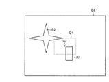
続いて、パターンマッチングに用いるレシピ画像について説明する。図2は、FPD検査装置1が行うレシピ画像登録処理を示すフローチャートである。また、図3,4は、レシピ画像を示す模式図である。まず、制御部20は、送受信部21を介して、撮像部161によって撮像されたレシピに登録されている測定座標における測定対象のパターンを含む画像を高倍率(倍率S1とする)で取得する(ステップS102)。取得された画像は、例えば、図3に示すように、少なくとも測定対象のパターンR1を含む高倍レシピ画像D1である。なお、高倍レシピ画像D1には、測定対象のパターンR1のほか、パターンR2の一部もフレーム内に入るように撮像されるているが、パターンR2がフレーム内に入らない画像であってもよい。
Next, a recipe image used for pattern matching will be described. FIG. 2 is a flowchart showing a recipe image registration process performed by the
高倍レシピ画像D1を取得後、高倍レシピ画像D1上で測定箇所を設定する(ステップS104)。図3に示すように、パターンR1における線幅を測定する測定箇所である測定ポイントP1,P2を設定する。測定ポイントP1,P2を設定することで、撮像画像内にパターンR1がある場合に、測定ポイントP1,P2間の距離を測定するように設定される。測定ポイントP1,P2は、例えば、パターンR1と基板表面との間の濃淡が変化する境界部分に設定される。 After acquiring the high-magnification recipe image D1, a measurement location is set on the high-magnification recipe image D1 (step S104). As shown in FIG. 3, measurement points P <b> 1 and P <b> 2 that are measurement points for measuring the line width in the pattern R <b> 1 are set. By setting the measurement points P1 and P2, when the pattern R1 is present in the captured image, the distance between the measurement points P1 and P2 is measured. The measurement points P1 and P2 are set, for example, at a boundary portion where the shading between the pattern R1 and the substrate surface changes.
高倍レシピ画像D1における測定箇所の設定が終了すると、制御部20は、この高倍レシピ画像D1を記憶部26に記憶させる(ステップS106)。
When the setting of the measurement location in the high-magnification recipe image D1 is completed, the
次に、この測定座標における画像を低倍率(倍率S2(<S1)とする)で取得する(ステップS108)。取得された画像は、図4に示すように、少なくとも高倍レシピ画像D1が含まれる低倍レシピ画像D2である。このとき、低倍レシピ画像D2の視野領域の面積は、高倍レシピ画像D1の視野領域の面積の2倍以上である。なお、図3,4に示すように、高倍レシピ画像D1の視野中心C1と低倍レシピ画像D2の視野中心C2は、一致していることが好ましい。 Next, an image at this measurement coordinate is acquired at a low magnification (magnification S2 (<S1)) (step S108). As shown in FIG. 4, the acquired image is a low-magnification recipe image D2 including at least a high-magnification recipe image D1. At this time, the area of the visual field area of the low-magnification recipe image D2 is at least twice the area of the visual field area of the high-magnification recipe image D1. As shown in FIGS. 3 and 4, it is preferable that the visual field center C1 of the high-magnification recipe image D1 and the visual field center C2 of the low-magnification recipe image D2 coincide.
低倍レシピ画像D2を取得すると、制御部20は、記憶部26にこの低倍レシピ画像D2を記憶させる(ステップS110)。上述したレシピ画像登録処理は、レシピに登録されている測定座標に関して行われる。測定座標が複数ある場合は、その測定座標分の高倍レシピ画像D1および低倍レシピ画像D2が取得され、記憶される。なお、基板Wに同一のパターンが複数形成されている場合は、各測定座標に共通してそれぞれ高倍レシピ画像および低倍レシピ画像を1画像ずつ登録してもよい。
When acquiring the low-magnification recipe image D2, the
図5は、FPD検査装置1が行う線幅測定処理を示すフローチャートである。また、図6〜8は、検査画像およびレシピ画像を示す模式図である。まず、制御部20は、光学ユニット16を測定座標に移動させる(ステップS202)。そして、制御部20は、測定座標における基板Wの画像を高倍率(倍率S1)で撮像し、図6に示す検査画像30として画像を取得する(ステップS204)。
FIG. 5 is a flowchart showing line width measurement processing performed by the
検査画像30を取得後、制御部20は、ステップS204で取得した検査画像30を(S2/S1)倍に縮小する(ステップS206)。この縮小処理によって、検査画像30と低倍レシピ画像D2とが同等の画素分解能となる。
After acquiring the
制御部20は、検査画像30を縮小した縮小画像40が、低倍レシピ画像D2上のどこに位置するかを検索部24に検索させる(ステップS208)。検索部24は、図7に示すように、縮小画像40の低倍レシピ画像D2内の位置の検索を行い、検査画像30が低倍レシピ画像D2上で位置する場所を判断する。
The
縮小画像40の低倍レシピ画像D2内における位置の検索が終了すると、制御部20は、検査画像30における測定箇所の位置を算出する(ステップS210)。このとき、制御部20は、例えば、検査画像30の視野中心C3の座標を算出する。
When the search for the position of the reduced
検査画像30の視野中心C3の座標が算出されると、制御部20は、算出された座標をもとに、検査画像30内に測定箇所があるか否かを判断する(ステップS212)。ここで、検査画像30内に測定箇所があると判断した場合(ステップS212:Yes)、制御部20は、ステップS218に移行して測定箇所の線幅測定処理を行う。制御部20は、例えば、図3に示した測定ポイントP1,P2間の距離を測定する。線幅測定終了後、制御部20は、次の測定座標がある場合(ステップS220:Yes)、ステップS202に移行して次の測定座標における線幅測定処理を行う。また、制御部20は、次の測定座標がない場合(ステップS220:No)、処理を終了する。
When the coordinates of the visual field center C3 of the
一方、制御部20は、検査画像30内に測定箇所がない(検査領域から外れている)と判断した場合(ステップS212:No)、検査画像30の測定箇所からのずれ量を算出する(ステップS214)。具体的には、図8に示すように、制御部20が、縮小画像40(検査画像30)の視野中心C3と低倍レシピ画像D2の視野中心C2との距離および方向を算出部25に算出させる。制御部20は、算出部25が算出したずれ量の距離および方向をもとに、光学ユニット16を高倍率(倍率S1)における視野が領域50となるように移動させる。
On the other hand, when the
制御部20は、光学ユニット16を移動後、高倍率(倍率S1)で画像を取得する(ステップS216)。画像を取得後、制御部20は、ステップS218に移行して線幅測定処理を行う。
After moving the
上述した本実施の形態によれば、測定箇所を含む高倍レシピ画像と、高倍レシピ画像を含み、高倍レシピ画像と比して広範囲な視野を有する低倍レシピ画像とを予め登録し、高倍率で取得した検査画像が検査領域から外れた場合に、検査画像を低倍レシピ画像の倍率と同等の画素分解能にして、検査画像の低倍レシピ画像における位置を検索するようにしたので、検査画像が検査領域から外れた場合であっても、光学系の倍率を切り替えることなく、測定箇所を含む検査画像を取得できる。また、複数回の取り直しおよびパターンマッチングを行うことなく、一度の移動動作で測定箇所を含む検査領域に光学ユニットを移動させることができる。これにより、検査対象の位置合わせにかかる検索時間を短縮して、検査時間の増大を抑制することができる。 According to the present embodiment described above, a high-magnification recipe image including a measurement location and a low-magnification recipe image including a high-magnification recipe image and having a wide field of view as compared with the high-magnification recipe image are registered in advance and at a high magnification. When the acquired inspection image deviates from the inspection area, the inspection image is set to the same pixel resolution as the magnification of the low-magnification recipe image, and the position of the inspection image in the low-magnification recipe image is searched. Even in the case of deviating from the inspection area, an inspection image including a measurement location can be acquired without switching the magnification of the optical system. In addition, the optical unit can be moved to the inspection region including the measurement location by a single movement operation without performing multiple re-taking and pattern matching. Thereby, it is possible to shorten the search time required for alignment of the inspection target and suppress an increase in the inspection time.
また、低倍レシピ画像の視野領域を、高倍レシピ画像の視野領域の2倍以上とすることで、検査画像が測定箇所から大きく外れたとしても、低倍レシピ画像内に検査画像が存在するため、低倍レシピ画像内にける検査画像の検索を確実なものとすることができる。 Further, by setting the field of view of the low-magnification recipe image to at least twice the field of view of the high-magnification recipe image, the inspection image exists in the low-magnification recipe image even if the inspection image deviates greatly from the measurement location. The inspection image search in the low-magnification recipe image can be ensured.
なお、算出部25が、画像の視野中心の座標を基準としてずれ量を算出するものとして説明したが、算出するための基準点(座標)は、画像のフレーム内の如何なる場所でもよい。例えば、フレームの角を基準点としてもよく、高倍レシピ画像D1内の測定箇所に対応する点を基準としてもよい。
Note that although the
以上のように、本発明にかかる位置合わせ装置、位置合わせ方法および位置合わせプログラムは、効率的なパターンマッチングを行ない、検査時間を短縮させることに有用である。 As described above, the alignment apparatus, alignment method, and alignment program according to the present invention are useful for performing efficient pattern matching and shortening the inspection time.
1 FPD検査装置
1a 基板処理部
1b 制御機構
11 ベースフレーム
12 ステージ
13 基板ホルダ
14 門型フレーム
15 Y軸部材
16 光学ユニット
17,18 移動機構
19 X軸部材
20 制御部
21 送受信部
22 入力部
23 出力部
24 検索部
25 算出部
26 記憶部
30 検査画像
40 縮小画像
161 顕微鏡
162 撮像部
C1〜C3 視野中心
D1 高倍レシピ画像
D2 低倍レシピ画像
R1,R2 パターン
W 基板
DESCRIPTION OF
Claims (6)
前記測定座標位置における測定対象のパターンを含む検査測定のための高倍レシピ画像、および前記高倍レシピ画像の視野領域が含まれる低倍レシピ画像を記憶する記憶部と、
前記測定座標位置において前記撮像部により高倍率で撮像された検査画像を前記低倍レシピ画像と同等の画素分解能となるように縮小処理し、この縮小画像が前記低倍レシピ画像のどの位置にあるか検索する検索部と、
前記検査画像に測定箇所がない場合に、前記検索部による検索結果に基づいて前記縮小画像と前記低倍レシピ画像に設定された前記高倍レシピ画像の視野領域とのずれ量と方向を算出する算出部と、
前記算出部で算出したずれ量と方向をもとに、前記基板上の測定座標位置に前記光学ユニットの視野が合うように前記光学ユニットと前記基板を相対移動させた後、前記撮像部で検査画像を撮像させる制御を行う制御部と、
を備えたことを特徴とする位置合わせ装置。 An optical unit and a substrate having an imaging unit by relatively moving the apparatus so I position if for positioning the optical unit to measure coordinate positions on the substrate that has been registered in the recipe,
A storage unit for storing a high-magnification recipe image for inspection measurement including a pattern to be measured at the measurement coordinate position, and a low-magnification recipe image including a visual field region of the high-magnification recipe image;
The inspection image captured at a high magnification by the imaging unit at the measurement coordinate position is reduced so as to have a pixel resolution equivalent to that of the low-magnification recipe image, and the reduced image is located at any position of the low-magnification recipe image. A search part to search,
Calculation for calculating a deviation amount and direction between the reduced image and the field of view of the high-magnification recipe image set in the low-magnification recipe image based on a search result by the retrieval unit when there is no measurement location in the inspection image And
Based on the deviation amount and direction calculated by the calculation unit, the optical unit and the substrate are relatively moved so that the field of view of the optical unit is aligned with the measurement coordinate position on the substrate, and then inspected by the imaging unit. A control unit that performs control to capture an image;
An alignment apparatus comprising:
前記測定座標位置における測定対象のパターンを含む検査測定のための高倍レシピ画像、および前記高倍レシピ画像の視野領域が含まれる低倍レシピ画像を記憶部に登録させるレシピ登録ステップと、
前記測定座標位置に前記光学ユニットを移動させ、前記測定座標位置において前記撮像部により前記高倍レシピ画像と同等の倍率で撮像する検査画像撮像ステップと、
前記検査画像撮像ステップで取得された検査画像を前記低倍レシピ画像と同等の画素分解能となるように縮小処理する縮小処理ステップと、
前記縮小処理ステップで縮小された縮小画像が前記低倍レシピ画像のどの位置にあるか検索する検索ステップと、
前記検査画像に測定箇所がない場合に、前記検索ステップによる検索結果に基づいて前記縮小画像と前記低倍レシピ画像に設定された前記高倍レシピ画像の視野領域とのずれ量と方向を算出する算出ステップと、
前記算出ステップで算出したずれ量と方向をもとに、前記基板上の測定座標位置に前記光学ユニットの視野が合うように前記光学ユニットと前記基板を相対移動させた後、前記撮像部で検査画像を撮像させる移動撮像ステップと、
を含むことを特徴とする位置合わせ方法。 An optical unit and a substrate having an imaging unit is relatively moved, a method was I position if positioning the optical unit to measure coordinate positions on the substrate that has been registered in the recipe,
A recipe registration step for registering a high-magnification recipe image for inspection measurement including a pattern to be measured at the measurement coordinate position, and a low-magnification recipe image including a visual field area of the high-magnification recipe image in a storage unit;
An inspection image imaging step of moving the optical unit to the measurement coordinate position and imaging at the measurement coordinate position by the imaging unit at a magnification equivalent to the high-magnification recipe image;
A reduction processing step for reducing the inspection image acquired in the inspection image imaging step so as to have a pixel resolution equivalent to that of the low-magnification recipe image;
A search step of the reduction process reduced image reduced at step searches whether which position of the low-magnification recipe image,
Calculation for calculating the amount and direction of deviation between the reduced image and the field of view of the high-magnification recipe image set in the low-magnification recipe image based on the retrieval result of the retrieval step when there is no measurement location in the inspection image Steps,
Based on the deviation amount and direction calculated in the calculation step, the optical unit and the substrate are relatively moved so that the field of view of the optical unit is aligned with the measurement coordinate position on the substrate, and then inspected by the imaging unit. A moving imaging step for capturing an image;
A registration method characterized by comprising:
前記測定座標位置における測定対象のパターンを含む検査測定のための高倍レシピ画像、および前記高倍レシピ画像の視野領域が含まれる低倍レシピ画像を記憶部に登録させるレシピ登録手順と、
前記測定座標位置に前記光学ユニットを移動させ、前記測定座標位置において前記撮像部により前記高倍レシピ画像と同等の倍率で撮像する検査画像撮像手順と、
前記検査画像撮像手順で取得された検査画像を前記低倍レシピ画像と同等の画素分解能となるように縮小処理する縮小処理手順と、
前記縮小処理手順で縮小された縮小画像が前記低倍レシピ画像のどの位置にあるか検索する検索手順と、
前記検査画像に測定箇所がない場合に、前記検索手順による検索結果に基づいて前記縮小画像と前記低倍レシピ画像に設定された前記高倍レシピ画像の視野領域とのずれ量と方向を算出する算出手順と、
前記算出手順で算出したずれ量と方向をもとに、前記基板上の測定座標位置に前記光学ユニットの視野が合うように前記光学ユニットと前記基板を相対移動させた後、前記撮像部で検査画像を撮像させる移動撮像手順と、
を実行させることを特徴とする位置合わせプログラム。 To the alignment device that moves the optical unit having the imaging unit relative to the substrate and aligns the optical unit with the measurement coordinate position on the substrate registered in the recipe,
Recipe registration procedure for registering a high-magnification recipe image for inspection measurement including a pattern to be measured at the measurement coordinate position, and a low-magnification recipe image including a field area of the high-magnification recipe image in a storage unit;
An inspection image imaging procedure for moving the optical unit to the measurement coordinate position and imaging at the measurement coordinate position by the imaging unit at a magnification equivalent to the high-magnification recipe image;
A reduction processing procedure for reducing the inspection image acquired in the inspection image imaging procedure so as to have a pixel resolution equivalent to that of the low-magnification recipe image;
A search procedure reduced image reduced by the reduction processing procedure searches where it is in the position of the low-magnification recipe image,
Calculation for calculating a deviation amount and a direction between the reduced image and the field-of-view area of the high-magnification recipe image set in the low-magnification recipe image based on a retrieval result by the retrieval procedure when there is no measurement location in the inspection image Procedure and
Based on the deviation amount and direction calculated in the calculation procedure, the optical unit and the substrate are relatively moved so that the field of view of the optical unit matches the measurement coordinate position on the substrate, and then inspected by the imaging unit. A moving imaging procedure for capturing an image;
An alignment program characterized in that
Priority Applications (4)
| Application Number | Priority Date | Filing Date | Title |
|---|---|---|---|
| JP2010250948A JP5653724B2 (en) | 2010-11-09 | 2010-11-09 | Alignment device, alignment method, and alignment program |
| TW100138492A TW201229500A (en) | 2010-11-09 | 2011-10-24 | Position alignment device, position alignment method, and computer readable recording medium having position alignment program recorded thereon |
| KR1020110115802A KR20120049826A (en) | 2010-11-09 | 2011-11-08 | Position alignment device, position alignment method, and computer readable recording medium having position alignment program recorded thereon |
| CN2011103530218A CN102565082A (en) | 2010-11-09 | 2011-11-09 | Position alignment device, position alignment method, and computer readable recording medium having position alignment program recorded thereon |
Applications Claiming Priority (1)
| Application Number | Priority Date | Filing Date | Title |
|---|---|---|---|
| JP2010250948A JP5653724B2 (en) | 2010-11-09 | 2010-11-09 | Alignment device, alignment method, and alignment program |
Publications (3)
| Publication Number | Publication Date |
|---|---|
| JP2012103072A JP2012103072A (en) | 2012-05-31 |
| JP2012103072A5 JP2012103072A5 (en) | 2013-12-12 |
| JP5653724B2 true JP5653724B2 (en) | 2015-01-14 |
Family
ID=46267519
Family Applications (1)
| Application Number | Title | Priority Date | Filing Date |
|---|---|---|---|
| JP2010250948A Expired - Fee Related JP5653724B2 (en) | 2010-11-09 | 2010-11-09 | Alignment device, alignment method, and alignment program |
Country Status (4)
| Country | Link |
|---|---|
| JP (1) | JP5653724B2 (en) |
| KR (1) | KR20120049826A (en) |
| CN (1) | CN102565082A (en) |
| TW (1) | TW201229500A (en) |
Families Citing this family (5)
| Publication number | Priority date | Publication date | Assignee | Title |
|---|---|---|---|---|
| US9852500B2 (en) * | 2015-07-15 | 2017-12-26 | GM Global Technology Operations LLC | Guided inspection of an installed component using a handheld inspection device |
| CN110268266B (en) * | 2017-02-08 | 2022-11-29 | 富士胶片株式会社 | Immunity inspection device |
| CN113125434A (en) * | 2019-12-31 | 2021-07-16 | 深圳迈瑞生物医疗电子股份有限公司 | Image analysis system and method of controlling photographing of sample image |
| CN112919106A (en) * | 2021-01-29 | 2021-06-08 | 中山市美鼎机械制造有限公司 | Circuit board optical intelligent detection equipment |
| JP2023032759A (en) * | 2021-08-27 | 2023-03-09 | 株式会社Screenホールディングス | Drawing system, drawing method and program |
Family Cites Families (10)
| Publication number | Priority date | Publication date | Assignee | Title |
|---|---|---|---|---|
| JPH0634233B2 (en) * | 1987-05-26 | 1994-05-02 | 株式会社安川電機 | Hierarchical structural template matching method |
| JP3246616B2 (en) * | 1992-10-01 | 2002-01-15 | 株式会社ニコン | Positioning method |
| JP2001201338A (en) * | 2000-01-20 | 2001-07-27 | Jeol Ltd | Coordinate link mechanism |
| JP3993817B2 (en) * | 2002-12-11 | 2007-10-17 | 株式会社日立製作所 | Defect composition analysis method and apparatus |
| JP4847685B2 (en) * | 2004-04-16 | 2011-12-28 | 株式会社日立ハイテクノロジーズ | Pattern search method |
| JP5059297B2 (en) * | 2005-05-09 | 2012-10-24 | 株式会社日立ハイテクノロジーズ | Electron beam observation device |
| JP2008152555A (en) * | 2006-12-18 | 2008-07-03 | Olympus Corp | Image recognition method and image recognition device |
| JP2008311668A (en) * | 2008-07-07 | 2008-12-25 | Hitachi High-Technologies Corp | Device and method for inspecting superposition error of patterns formed on substrate or semiconductor wafer |
| JP2010107412A (en) * | 2008-10-31 | 2010-05-13 | Toshiba Corp | Defect observation device and method of observing defects |
| JP5315076B2 (en) * | 2009-02-06 | 2013-10-16 | 株式会社日立ハイテクノロジーズ | Semiconductor inspection method and apparatus considering influence of electron beam |
-
2010
- 2010-11-09 JP JP2010250948A patent/JP5653724B2/en not_active Expired - Fee Related
-
2011
- 2011-10-24 TW TW100138492A patent/TW201229500A/en unknown
- 2011-11-08 KR KR1020110115802A patent/KR20120049826A/en not_active Application Discontinuation
- 2011-11-09 CN CN2011103530218A patent/CN102565082A/en active Pending
Also Published As
| Publication number | Publication date |
|---|---|
| KR20120049826A (en) | 2012-05-17 |
| CN102565082A (en) | 2012-07-11 |
| TW201229500A (en) | 2012-07-16 |
| JP2012103072A (en) | 2012-05-31 |
Similar Documents
| Publication | Publication Date | Title |
|---|---|---|
| KR101735403B1 (en) | Inspection method, templet substrate and focus offset method | |
| KR101367485B1 (en) | Method and apparatus for measuring dimensional changes in transparent substrates | |
| JP5193112B2 (en) | Inspection condition data generation method and inspection system for semiconductor wafer appearance inspection apparatus | |
| JP5653724B2 (en) | Alignment device, alignment method, and alignment program | |
| US8115808B2 (en) | Coordinate measuring machine and method for calibrating the coordinate measuring machine | |
| JP2006329714A (en) | Lens inspection apparatus | |
| JP2006276454A (en) | Image correcting method and pattern defect inspecting method using same | |
| KR20170032602A (en) | Defect imaging apparatus for imaging defects, Defect inspection system having the same and method of inspecting defects using the same inspection system | |
| JP5178781B2 (en) | Sensor output data correction device and sensor output data correction method | |
| JP4560898B2 (en) | Inspection apparatus and inspection method | |
| KR20040091562A (en) | Substrate testing device and substrate testing method | |
| US7675633B2 (en) | Method for measuring positions of structures on a substrate with a coordinate measuring machine | |
| CN117558643A (en) | Detection method of wafer EBR region | |
| KR100597026B1 (en) | A method of detecting a pattern and an apparatus thereof | |
| JP2013117490A (en) | Inspection system and method for setting recipe | |
| JP4277026B2 (en) | Pattern inspection apparatus and pattern inspection method | |
| JP4313162B2 (en) | Alignment mark detection method and inspection apparatus | |
| KR101754598B1 (en) | System for testing panel using focus mapping scheme and method thereof | |
| KR102672568B1 (en) | Mask posture monitoring method, device, and mask particle size detection equipment | |
| US20100150430A1 (en) | Visual inspection apparatus and visual inspection method for semiconductor laser chip or semiconductor laser bar | |
| JP2012154975A (en) | Focusing device, focusing method, and focusing program | |
| JP2007292683A (en) | Sample measuring apparatus and sample stage adjusting method of sample measuring apparatus | |
| JP6018929B2 (en) | Inspection method | |
| JP3520809B2 (en) | Lead frame shape measuring device and lead frame shape measuring method using this device | |
| JP4632471B2 (en) | Inspection device |
Legal Events
| Date | Code | Title | Description |
|---|---|---|---|
| A521 | Written amendment |
Free format text: JAPANESE INTERMEDIATE CODE: A523 Effective date: 20131029 |
|
| A621 | Written request for application examination |
Free format text: JAPANESE INTERMEDIATE CODE: A621 Effective date: 20131029 |
|
| A131 | Notification of reasons for refusal |
Free format text: JAPANESE INTERMEDIATE CODE: A131 Effective date: 20140318 |
|
| A977 | Report on retrieval |
Free format text: JAPANESE INTERMEDIATE CODE: A971007 Effective date: 20140319 |
|
| A521 | Written amendment |
Free format text: JAPANESE INTERMEDIATE CODE: A523 Effective date: 20140519 |
|
| TRDD | Decision of grant or rejection written | ||
| A01 | Written decision to grant a patent or to grant a registration (utility model) |
Free format text: JAPANESE INTERMEDIATE CODE: A01 Effective date: 20141111 |
|
| A61 | First payment of annual fees (during grant procedure) |
Free format text: JAPANESE INTERMEDIATE CODE: A61 Effective date: 20141119 |
|
| S531 | Written request for registration of change of domicile |
Free format text: JAPANESE INTERMEDIATE CODE: R313531 |
|
| R350 | Written notification of registration of transfer |
Free format text: JAPANESE INTERMEDIATE CODE: R350 |
|
| LAPS | Cancellation because of no payment of annual fees |