JP5659029B2 - Stage mechanism and DNA sequencer using stage mechanism - Google Patents
Stage mechanism and DNA sequencer using stage mechanism Download PDFInfo
- Publication number
- JP5659029B2 JP5659029B2 JP2011014688A JP2011014688A JP5659029B2 JP 5659029 B2 JP5659029 B2 JP 5659029B2 JP 2011014688 A JP2011014688 A JP 2011014688A JP 2011014688 A JP2011014688 A JP 2011014688A JP 5659029 B2 JP5659029 B2 JP 5659029B2
- Authority
- JP
- Japan
- Prior art keywords
- stage
- joint
- feed screw
- torsional rigidity
- screw shaft
- Prior art date
- Legal status (The legal status is an assumption and is not a legal conclusion. Google has not performed a legal analysis and makes no representation as to the accuracy of the status listed.)
- Active
Links
- 230000007246 mechanism Effects 0.000 title claims description 70
- 239000012530 fluid Substances 0.000 claims description 15
- 239000011553 magnetic fluid Substances 0.000 claims description 15
- 238000006243 chemical reaction Methods 0.000 claims description 10
- 230000005684 electric field Effects 0.000 claims description 9
- 239000003153 chemical reaction reagent Substances 0.000 claims description 6
- 239000002184 metal Substances 0.000 claims description 6
- 238000003384 imaging method Methods 0.000 claims 5
- 108020004414 DNA Proteins 0.000 description 16
- 102000053602 DNA Human genes 0.000 description 16
- 238000010586 diagram Methods 0.000 description 10
- 230000008878 coupling Effects 0.000 description 9
- 238000010168 coupling process Methods 0.000 description 9
- 238000005859 coupling reaction Methods 0.000 description 9
- 230000001133 acceleration Effects 0.000 description 5
- 150000007523 nucleic acids Chemical group 0.000 description 5
- 238000013016 damping Methods 0.000 description 4
- 230000000694 effects Effects 0.000 description 4
- 238000005259 measurement Methods 0.000 description 4
- 108091028043 Nucleic acid sequence Proteins 0.000 description 3
- 238000000034 method Methods 0.000 description 3
- 230000004044 response Effects 0.000 description 3
- 230000000007 visual effect Effects 0.000 description 3
- 230000008859 change Effects 0.000 description 2
- 230000000052 comparative effect Effects 0.000 description 2
- 238000006073 displacement reaction Methods 0.000 description 2
- 230000005284 excitation Effects 0.000 description 2
- 102000039446 nucleic acids Human genes 0.000 description 2
- 108020004707 nucleic acids Proteins 0.000 description 2
- 206010023230 Joint stiffness Diseases 0.000 description 1
- 230000003287 optical effect Effects 0.000 description 1
- 230000000638 stimulation Effects 0.000 description 1
- 230000001629 suppression Effects 0.000 description 1
Images
Landscapes
- Details Of Measuring And Other Instruments (AREA)
- Microscoopes, Condenser (AREA)
- Vibration Prevention Devices (AREA)
- Transmission Devices (AREA)
- Apparatus Associated With Microorganisms And Enzymes (AREA)
Description
本発明は、送りねじ駆動機構(ステージ機構)、およびこれを用いてDNA(デオキシリボ核酸)などの核酸の塩基配列を解読するための核酸配列解析装置に関わる。 The present invention relates to a feed screw driving mechanism (stage mechanism) and a nucleic acid sequence analyzing apparatus for decoding a base sequence of a nucleic acid such as DNA (deoxyribonucleic acid) using the same.
1990年代に推進されたヒトゲノム計画などの大型プロジェクトでは、ゲノム解読は専門の大規模な解読センターにおいて行われていたが、今後、医療現場において個人レベルのゲノム配列解読をルーチンワークとして行えるようにするためには、配列解読の時間短縮、すなわち高スループット化が必要となる。このようなニーズに応えるため、今後、核酸配列解析装置(以下、DNAシーケンサと称する)においては、装置スループットの向上が必須となっている。 In large-scale projects such as the Human Genome Project promoted in the 1990s, genome decoding was performed at a specialized large-scale decoding center. For this purpose, it is necessary to shorten the sequence decoding time, that is, to increase the throughput. In order to meet such needs, in the future, in nucleic acid sequence analyzers (hereinafter referred to as DNA sequencers), it is essential to improve apparatus throughput.
DNAシーケンサでは、塩基伸長反応を逐次進行させる化学反応の結果を光学的に計測する。このため、装置スループットの向上のためには、化学反応に要する時間と光学計測時間の両方を短縮することが重要である。化学反応の結果を計測する際には、対物レンズ直下に観察サンプルを搭載したフローセルを配置し、このフローセルはセルホルダに固定され、さらにセルホルダはXYステージの可動テーブル上に固定される(特許文献2参照)。XYステージを計測視野の大きさだけ逐次移動させることにより、フローセル上の観察サンプルと試薬の反応状態を撮像して、光学的に塩基配列情報を検出する。したがって、装置スループットを向上するためには、XYステージの高速化が必須となる。 A DNA sequencer optically measures the result of a chemical reaction that causes a base extension reaction to proceed sequentially. For this reason, in order to improve the apparatus throughput, it is important to shorten both the time required for the chemical reaction and the optical measurement time. When measuring the result of the chemical reaction, a flow cell equipped with an observation sample is arranged directly under the objective lens, the flow cell is fixed to the cell holder, and the cell holder is fixed to the movable table of the XY stage (Patent Document 2). reference). By sequentially moving the XY stage by the size of the measurement visual field, the reaction state of the observation sample on the flow cell and the reagent is imaged, and the base sequence information is optically detected. Therefore, in order to improve apparatus throughput, it is essential to increase the speed of the XY stage.
このようなステージの高速化、すなわち、ステージの送り速度と加速度の増加は、装置振動の増大につながることが多く、特に、送りねじ(ボールねじ)駆動のステージでは、ステージの高速化と装置振動の抑制を両立させることがしばしば課題となる。送りねじを用いた駆動機構の場合、これを回転駆動手段(モータ)の軸と被駆動側の送りねじの軸を連結して動力を伝達するための継手(カップリング)が用いられ、この継手のねじり剛性の大小により、ステージの移動に伴う振動の発生状況が変わることが知られている。すなわち、継手のねじり剛性が高いほど駆動力に対する追従性は高くなるが、その反面、減衰効果は低下するため、送りねじに振動的な挙動が発生しやすくなる。 Increasing the speed of the stage, that is, increasing the feed speed and acceleration of the stage often leads to an increase in apparatus vibration. In particular, in a stage driven by a feed screw (ball screw), the speed of the stage and the apparatus vibration are increased. It is often a challenge to achieve both suppression. In the case of a drive mechanism using a feed screw, a coupling (coupling) for transmitting power by connecting the shaft of the rotational drive means (motor) and the shaft of the driven screw on the driven side is used. It is known that the state of occurrence of vibrations accompanying the movement of the stage changes depending on the torsional rigidity. That is, the higher the torsional rigidity of the joint, the higher the followability with respect to the driving force, but on the other hand, the damping effect is reduced, so that vibration behavior is likely to occur in the feed screw.
DNAシーケンサに用いる旨の開示はないが、このような送りねじ駆動機構の継手に関する公知例としては、特許文献1に記載されているフレキシブルカップリングが挙げられる。
Although there is no disclosure of use in a DNA sequencer, a known example of a joint of such a feed screw drive mechanism is a flexible coupling described in
上述の特許文献1では、駆動側と被駆動側の2軸を連結する部材の間に、緩衝たわみ部材を内蔵した減衰アダプタと剛性の高い金属ばねとで構成したたわみ連結部を装着した構造により、金属板ばねカップリングと同等のねじり剛性を有しつつ、適度の減衰効果を有するカップリングについて記載されている。
In the above-mentioned
しかしながら、このような継手(カップリング)では、そのねじり剛性と緩衝たわみ部材の粘性係数は固定であるため、これを送りねじ駆動機構に適用し、様々な条件で動作させた際、必ずしも所望の動作特性が得られるとは限らない。 However, in such a coupling (coupling), its torsional rigidity and the viscosity coefficient of the buffer deflection member are fixed. Therefore, when this is applied to a feed screw drive mechanism and operated under various conditions, it is not always desired. Operational characteristics are not always obtained.
また、次世代DNAシーケンサにおいては、対物レンズ直下に観察サンプルを搭載したフローセルを配置し、このフローセルはセルホルダに固定され、さらにセルホルダはXYステージ上の可動テーブルに固定される。ここで、送りねじで駆動されるXYステージを計測視野の大きさだけ逐次移動させることにより、フローセル上の観察サンプルと試薬の反応状態を撮像して、光学的に塩基配列情報を検出する。しかし、送りねじ駆動のXYステージは、高速・高加減速に伴う振動の増大などにより、単純にXYステージの移動速度を高速にするだけでは装置スループットの向上は困難である。これは、高速・高加減速に伴う負荷の増大により加振力が増加し、画像取得を行う際の振動が発生して安定した画像取得を行うことが困難となるためである。このような振動を励起しない程度に移動速度を低下させると、結果としてスループットの向上が困難となってしまう。上記の特許文献1でも、ねじり剛性と緩衝たわみ部材の粘性係数は固定であるため、この問題を解決することは難しいと考えられる。
In the next-generation DNA sequencer, a flow cell on which an observation sample is mounted is disposed immediately below the objective lens, the flow cell is fixed to the cell holder, and the cell holder is further fixed to a movable table on the XY stage. Here, by sequentially moving the XY stage driven by the feed screw by the size of the measurement visual field, the reaction state of the observation sample and the reagent on the flow cell is imaged, and the base sequence information is optically detected. However, it is difficult to improve the apparatus throughput of a feed screw driven XY stage simply by increasing the movement speed of the XY stage due to an increase in vibration accompanying high speed and high acceleration / deceleration. This is because the excitation force increases due to an increase in load accompanying high speed and high acceleration / deceleration, and vibration during image acquisition occurs, making it difficult to perform stable image acquisition. If the moving speed is reduced to such an extent that such vibrations are not excited, it will be difficult to improve the throughput. Even in the
本発明の目的は、高いスループットを維持しつつ、振動を抑えた、次世代のDNAシーケンサに用いるステージ機構を提供することである。 An object of the present invention is to provide a stage mechanism for use in a next-generation DNA sequencer that maintains high throughput and suppresses vibrations.
上記課題を達成するために、送りねじと、この送りねじに螺合されるナットと、ナットに取り付けられる被送り部材と、送りねじを回転させる回転駆動手段と、回転駆動手段と送りねじを連結するねじり剛性可変機構付き継手と、回転駆動手段およびねじり剛性可変機構付き継手を制御する手段を備えることを特徴とするステージ機構を提供する。 To achieve the above object, a feed screw, a nut screwed to the feed screw, a feed member attached to the nut, a rotation drive means for rotating the feed screw, and the rotation drive means and the feed screw are connected. There is provided a stage mechanism comprising: a joint with a torsional rigidity variable mechanism, and means for controlling the rotation drive means and the joint with a torsional rigidity variable mechanism.
さらに、前記ステージ機構の被送り部材上に観察サンプルを搭載したフローセルを固定し、フローセル上の観察サンプルと試薬の反応状態を撮像して、光学的に塩基配列情報を検出することを特徴とするDNAシーケンサを提供する。 Furthermore, the flow cell carrying the observation sample is fixed on the member to be fed of the stage mechanism, the reaction state of the observation sample on the flow cell and the reagent is imaged, and the base sequence information is optically detected. A DNA sequencer is provided.
本発明によれば、ステージ機構の被送り部材の動きに合わせて、継手のねじり剛性を適切に変化させることにより、被送り部材の移動中および停止時の振動が低減される。これにより、本ステージ機構を備えたDNAシーケンサのスループット向上が図れる。 According to the present invention, the torsional rigidity of the joint is appropriately changed in accordance with the movement of the fed member of the stage mechanism, thereby reducing vibration during movement and stopping of the fed member. Thereby, the throughput of the DNA sequencer provided with this stage mechanism can be improved.
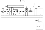
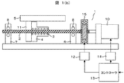
本発明の第1の実施例として、ねじり剛性可変機構付き継手を備えた送りねじ駆動機構について図1(a),図1(b)を用いて以下に説明する。図1(a)が本発明の実施例を示すための図であり、図1(b)がその比較例を示すための図である。 As a first embodiment of the present invention, a feed screw driving mechanism provided with a joint with a torsional rigidity variable mechanism will be described below with reference to FIGS. 1 (a) and 1 (b). FIG. 1A is a diagram for illustrating an example of the present invention, and FIG. 1B is a diagram for illustrating a comparative example thereof.
図1(b)に示すように、送りねじ駆動機構1は、送りねじ軸2と、この送りねじ軸2に多数のボール3を介して装着されるナット4と、このナット4に取り付けられる被送り部材としての可動テーブル5と、ホルダ11を備えている。送りねじ軸2には第1,第2軸受台6,7にサポートベアリング8を介して回転自在にかつ軸方向に固定状態に支持されており、送りねじ軸2の一端、この実施例では第1軸受台6側の端部が継手9を介して回転駆動源としての回転駆動手段10が連結されている。回転駆動手段10はコントローラ13によってモータドライバ14を介して制御されている。
As shown in FIG. 1B, the feed
この回転駆動手段10の具体的な装置としては、ステッピングモータ,DCサーボモータ,ACサーボモータなどを利用することができる。 As a specific device of the rotation driving means 10, a stepping motor, a DC servo motor, an AC servo motor, or the like can be used.
そして、この送りねじ駆動機構1には駆動時に軸力およびトルク等の力が作用しており、この力作用部に継手9が設けられている。トルクは送りねじ軸2からナット4に伝達され、ナット4から可動テーブル5を支持する図示しない左右のガイド部材に伝えられる。また、軸力は可動テーブル5からナット4を介して送りねじ軸2を通じて各軸受台6,7に伝達される。
A force such as an axial force and a torque acts on the feed
図1(a)の送りねじ駆動機構1は、送りねじ軸2と、この送りねじ軸2に多数のボール3を介して装着されるナット4と、このナット4に取り付けられる被送り部材としての可動テーブル5と、を備えている。送りねじ軸2は第1,第2軸受台6,7にサポートベアリング8を介して回転自在にかつ軸方向に固定状態に支持されており、送りねじ軸2の一端、この実施例では第1軸受台6側の端部がねじり剛性可変機構付き継手15を介して回転駆動源としての回転駆動手段10が連結されている。回転駆動手段10はコントローラ13によってモータドライバ14を介して制御されている。ねじり剛性可変機構付き継手15は、回転駆動手段10の駆動トルクを伝達する継手のねじり剛性を移動パターンに応じて適切に変化させることにより、高速・低振動・高停止安定性駆動を実現させるものである。次に、継手9のねじり剛性の違いによる振動と停止安定性に対する影響を、図2(a)および(b)を用いて以下に説明する。
The feed
図2(a)は、図1(a)の継手9をねじり剛性が高剛性,中剛性,低剛性のものに置き換えて、ステージを位置決めした際の位置応答波形を示している。また、図2(b)は図2(a)の停止時の拡大図である。図2(a)から継手9のねじり剛性が高剛性であるほど、移動中の振動が大きいことがわかる。また、図2(b)から継手9のねじり剛性が低剛性であるほど、位置決め後の停止安定性が低いことがわかる。その理由は、高剛性継手の場合には、減衰性が乏しいのでダンパー効果が得られず、振動が励起され、一方、低剛性継手の場合には、振動を吸収する減衰性があり、振動は励起されにくいが、剛性が低いために停止安定性が悪いことにある。したがって、継手9のねじり剛性が高剛性の場合は、振動は大きいが停止安定性が高く、継手9のねじり剛性が低剛性の場合は、振動は小さいが停止安定性が低いことを示している。一般的にねじり剛性が一定である継手9を用いた送りねじ駆動機構では、低振動と高停止安定性を両立することは困難である。そこで本発明では、ねじり剛性可変機構付き継手15を移動パターンに応じて適切に変化させる制御をすることにより、高速・低振動・高停止安定性の送りねじ駆動機構を可能とする。 FIG. 2A shows a position response waveform when the stage is positioned by replacing the joint 9 of FIG. 1A with one having high torsional rigidity, medium rigidity, and low rigidity. Moreover, FIG.2 (b) is an enlarged view at the time of a stop of Fig.2 (a). It can be seen from FIG. 2A that the higher the torsional rigidity of the joint 9, the greater the vibration during movement. Further, FIG. 2B shows that the lower the torsional rigidity of the joint 9, the lower the stop stability after positioning. The reason for this is that in the case of a high-rigidity joint, the damping effect is poor, so the damper effect cannot be obtained, and vibration is excited. Although it is difficult to be excited, the stability is low due to low rigidity. Therefore, when the torsional rigidity of the joint 9 is high, the vibration is large but the stop stability is high. When the torsional rigidity of the joint 9 is low, the vibration is small but the stop stability is low. . In general, in a feed screw driving mechanism using a joint 9 having a constant torsional rigidity, it is difficult to achieve both low vibration and high stopping stability. Therefore, in the present invention, a feed screw drive mechanism with high speed, low vibration, and high stop stability is made possible by controlling the joint 15 with a variable torsional rigidity mechanism appropriately according to the movement pattern.
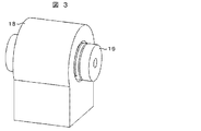
図3および図4は、ねじり剛性可変機構付き継手15の基本形を示すもので、以下この基本形について、説明するものとする。図3および図4は、ねじり剛性可変機構付き継手15の斜視図および断面図である。ねじり剛性可変機構付き継手15は、低剛性継手16と図示しない可変粘性体を封入しているカバー19と可変粘性体を外部刺激により粘性を変化させるための可変粘性体操作部(例えば、電磁コイル)17と可変粘性体操作部17を固定するための可変粘性体操作部固定子18と備えた機構である。
3 and 4 show a basic form of the joint 15 with a torsional rigidity variable mechanism, and this basic form will be described below. 3 and 4 are a perspective view and a cross-sectional view of the joint 15 with a torsional rigidity variable mechanism. The joint 15 with a variable torsional rigidity mechanism includes a low-rigid joint 16, a
可変粘性体として磁性流体を用いた場合、ねじり剛性可変機構付き継手15の原理を図4を用いて具体的に以下に説明する。 When a magnetic fluid is used as the variable viscous body, the principle of the joint 15 with a torsional stiffness variable mechanism will be specifically described below with reference to FIG.
磁性流体が低剛性継手16の溝に充填され、磁界が発生してないとき磁性流体は単なる流体であり、継手のねじり剛性は低剛性である。可変粘性体操作部17としての電磁コイルを低剛性継手16の外周上に設置し、電流を流すことで、トルク作用軸上に磁界を発生させ、溝の間にある磁性流体が磁界方向に固化することにより、継手のねじり剛性が高剛性となる。
When the magnetic fluid is filled in the groove of the low-rigid joint 16 and no magnetic field is generated, the magnetic fluid is a simple fluid, and the torsional rigidity of the joint is low. An electromagnetic coil as the variable viscous
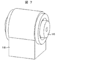
またこの作用は磁性流体だけではなく、他の可変粘性体、例えば、電気粘性流体を用いても同様のねじり剛性可変機構付き継手15が得られる。具体的な方法として、図7および図8を用いて以下に説明する。 In addition, the joint 15 having the same torsional rigidity variable mechanism can be obtained by using not only the magnetic fluid but also another variable viscous body, for example, an electrorheological fluid. As a specific method, it demonstrates below using FIG. 7 and FIG.
電気粘性流体が低剛性継手16の溝に充填され、電界が発生してないとき電気粘性流体は単なる流体であり、継手のねじり剛性は低剛性である。可変粘性体操作部17としての電極(不図示)をトルク作用軸上に垂直に設置し、電圧を印加することで、トルク作用軸上に電界を発生させ、溝の間にある電気粘性流体が電界方向に固化することにより、継手のねじり剛性が高剛性となる。
When the electrorheological fluid is filled in the groove of the low-rigidity joint 16 and no electric field is generated, the electrorheological fluid is merely a fluid, and the torsional rigidity of the joint is low. An electrode (not shown) as the variable viscous
また、図3および図4の低剛性継手16は円筒の金属を溝加工し金属ばねにすることで低剛性継手16としているが、弾性部材を利用している低剛性継手を用いて、その周囲を可変粘性体により被い、可変粘性体操作部17によって、ねじり剛性を可変として、ねじり剛性可変機構付き継手を構成することができる。
Further, the low-rigidity joint 16 in FIGS. 3 and 4 is formed as a low-rigidity joint 16 by grooving a cylindrical metal into a metal spring, but by using a low-rigidity joint using an elastic member, Can be covered with a variable viscous body and the torsional rigidity can be varied by the variable viscous
次に、ねじり剛性可変機構付き継手15の制御方法について、図1(b)を用いて以下に説明する。 Next, a control method of the joint 15 with a torsional rigidity variable mechanism will be described below with reference to FIG.
前述よりねじり剛性可変機構付き継手15は、高速移動中は継手のねじり剛性を低剛性とし、移動終了直前に継手のねじり剛性を高剛性にすることで高速・低振動・高停止安定性を実現する。ねじり剛性可変機構付き継手15を制御するD/Aボード12とモータドライバ14と接続されているコントローラ13は、移動パターンを生成し、その移動パターンに応じた継手のねじり剛性可変パターンを生成し、回転駆動手段10とねじり剛性可変機構付き継手15を制御する。
As mentioned above, the joint 15 with variable torsional rigidity mechanism has low torsional rigidity during high-speed movement, and high rigidity of the joint immediately before the end of movement to achieve high speed, low vibration and high stop stability. To do. The
移動パターンに応じた適切な継手のねじり剛性可変パターンについて、図5(a),(b),(c)を用いて以下に説明する。 An appropriate joint torsional rigidity variable pattern according to the movement pattern will be described below with reference to FIGS. 5 (a), 5 (b), and 5 (c).
図5(a)は、送りねじ駆動機構1における可動テーブル5の移動パターンである。図5(b)は、最も簡単な可動テーブル5の移動パターンに応じた継手のねじり剛性可変パターンである。継手のねじり剛性可変パターンは、高速移動中は継手のねじり剛性を低剛性とし、停止直前に継手のねじり剛性を高剛性となるように単純にねじり剛性を切り替えている。しかし、この方法では停止直前にねじり剛性が不連続に切り替わり、装置によっては切り替えた瞬間に振動を励起し、停止安定性が低くなる可能性がある。
FIG. 5A shows a movement pattern of the movable table 5 in the feed
図5(c)は、停止直前でねじれ剛性を連続的に切り替えた、継手のねじり剛性可変パターンである。この継手のねじり剛性可変パターンを用いれば、高速・低振動・高停止安定性の送りねじ駆動機構が可能である。 FIG. 5C is a joint torsional stiffness variable pattern in which the torsional stiffness is continuously switched immediately before stopping. By using this variable torsional rigidity pattern of the joint, a feed screw drive mechanism with high speed, low vibration and high stop stability is possible.
また機能性流体を磁性流体とした場合、継手のねじり剛性可変パターンは、可変粘性体操作部17である電磁コイルに電流を流すことで実現できる。つまり、図5(b)および(c)の継手のねじり剛性可変パターンと同様のパターンで、電磁コイルに電流を流すことで、磁界が発生し、磁性流体が固体化することで、ねじり剛性可変機構付き継手15のねじり剛性可変パターンの通りに制御する。
When the functional fluid is a magnetic fluid, the torsional rigidity variable pattern of the joint can be realized by passing an electric current through the electromagnetic coil that is the variable viscous
その他の可変粘性体として電気粘性流体を利用した場合は、図5(b)および(c)と同様のパターンの電圧を印加すればよい。 When an electrorheological fluid is used as another variable viscous body, a voltage having the same pattern as in FIGS. 5B and 5C may be applied.
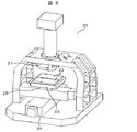
次に、本発明のねじり剛性可変機構付き継手を備えた送りねじ駆動機構を用いたDNAシーケンサの実施例について、図6を用いて以下に説明する。 Next, an embodiment of a DNA sequencer using a feed screw drive mechanism provided with a joint with a torsional rigidity variable mechanism of the present invention will be described below with reference to FIG.
DNA(デオキシリボ核酸)などの核酸の塩基配列を解読するための核酸配列解析装置としてDNAシーケンサ20がある。対物レンズ21直下に観察サンプルを搭載したフローセル22を配置し、このフローセル22はセルホルダ23に固定され、さらにセルホルダ23はXYステージ24上の可動テーブル25に固定される。ここで、送りねじで駆動されるXYステージ24を計測視野の大きさだけ逐次移動させることにより、フローセル上の観察サンプルと試薬の反応状態を撮像して、光学的に塩基配列情報を検出する。しかし、送りねじ駆動のXYステージ24は、高速・高加減速に伴う振動の増大などにより、単純にXYステージ24の移動速度を高速にするだけでは装置スループットの向上は困難である。これは、高速・高加減速に伴う負荷の増大により加振力が増加し、画像取得を行う際の振動が発生して安定した画像取得を行うことが困難となるためである。
There is a
そこで、図1(a)に示したねじり剛性可変機構付き継手を備えたステージ機構を採用することで、高速・低振動・高停止安定性が確保でき、DNAシーケンサのスループット向上が図れる。 Therefore, by adopting the stage mechanism including the joint with the torsional rigidity variable mechanism shown in FIG. 1A, high speed, low vibration, and high stop stability can be secured, and the throughput of the DNA sequencer can be improved.
また、ステージ機構の高速・低振動・高停止安定性を実現するために高価なサーボモータやセンサを使用せずに、性能を最大限に引き出すことができ、装置コストの低減が可能となる。 Further, the performance can be maximized without using an expensive servo motor or sensor in order to realize high speed, low vibration, and high stop stability of the stage mechanism, and the apparatus cost can be reduced.
1 送りねじ駆動機構
2 送りねじ軸
3 ボール
4 ナット
5,25 可動テーブル
6 第1軸受台
7 第2軸受台
8 サポートベアリング
9 継手
10 回転駆動手段
11 ホルダ
12 D/Aボード
13 コントローラ
14 モータドライバ
15 ねじり剛性可変機構付き継手
16 低剛性継手
17 可変粘性体操作部
18 可変粘性体操作部固定子
19 カバー
20 DNAシーケンサ
21 対物レンズ
22 フローセル
23 セルホルダ
24 XYステージ
DESCRIPTION OF
Claims (15)
前記継手は、溝を有する弾性体と、前記溝に充填された磁性流体と、前記磁性流体を前記溝に閉じ込めるカバーと、磁場を印加する電磁コイルと、電磁コイルを固定するための固定子とを備え、
弾性体、磁性流体、およびカバーは、電磁コイルが固定された固定子の内側に当該固定子との間に隙間を持って配置されている、ステージ機構。 A feed screw shaft, a nut that is screwed to the feed screw shaft and to which a stage is attached, a rotation drive means that rotates the feed screw shaft, a joint that connects the rotation drive means and the feed screw, Comprising control means for controlling torsional stiffness ;
The joint includes an elastic body having a groove, a magnetic fluid filled in the groove, a cover for confining the magnetic fluid in the groove, an electromagnetic coil for applying a magnetic field, and a stator for fixing the electromagnetic coil. With
The stage mechanism in which the elastic body, the magnetic fluid, and the cover are disposed with a gap between the stator and the stator to which the electromagnetic coil is fixed .
前記継手は、溝を有する弾性体と、前記溝に充填された電気粘性流体と、電場を印加する電極と、前記磁性流体を前記溝に閉じ込めるカバーと、電場を印加する電極と、電極を固定するための固定子とを備え、The joint includes an elastic body having a groove, an electrorheological fluid filled in the groove, an electrode for applying an electric field, a cover for confining the magnetic fluid in the groove, an electrode for applying an electric field, and fixing the electrode. And a stator for
弾性体、電気粘性流体、およびカバーは、電磁コイルが固定された固定子の内側に当該固定子との間に隙間を持って配置されている、ステージ機構。The stage mechanism, wherein the elastic body, the electrorheological fluid, and the cover are disposed with a gap between the stator and the stator to which the electromagnetic coil is fixed.
ステージと、Stage,
前記ステージ上に固定されたフローセルと、前記フローセル上の観察サンプルと試薬の反応状態を画像として撮像するための撮像手段と、前記画像を解析して塩基配列情報を検出する解析手段とを備え、A flow cell fixed on the stage, an imaging means for imaging the reaction state of the observation sample and reagent on the flow cell as an image, and an analysis means for analyzing the image and detecting base sequence information,
前記継手は、溝を有する弾性体と、前記溝に充填された磁性流体と、前記磁性流体を前記溝に閉じ込めるカバーと、磁場を印加する電磁コイルと、電磁コイルを固定するための固定子とを備え、The joint includes an elastic body having a groove, a magnetic fluid filled in the groove, a cover for confining the magnetic fluid in the groove, an electromagnetic coil for applying a magnetic field, and a stator for fixing the electromagnetic coil. With
弾性体、磁性流体、およびカバーは、電磁コイルが固定された固定子の内側に当該固定子との間に隙間を持って配置されている、The elastic body, the magnetic fluid, and the cover are arranged with a gap between the stator and the stator to which the electromagnetic coil is fixed.
ことを特徴とするDNAシーケンサ。DNA sequencer characterized by the above.
ステージと、Stage,
前記ステージ上に固定されたフローセルと、前記フローセル上の観察サンプルと試薬の反応状態を画像として撮像するための撮像手段と、前記画像を解析して塩基配列情報を検出する解析手段とを備え、A flow cell fixed on the stage, an imaging means for imaging the reaction state of the observation sample and reagent on the flow cell as an image, and an analysis means for analyzing the image and detecting base sequence information,
前記継手は、溝を有する弾性体と、前記溝に充填された電気粘性流体と、電場を印加する電極と、前記磁性流体を前記溝に閉じ込めるカバーと、電場を印加する電極と、電極を固定するための固定子とを備え、The joint includes an elastic body having a groove, an electrorheological fluid filled in the groove, an electrode for applying an electric field, a cover for confining the magnetic fluid in the groove, an electrode for applying an electric field, and fixing the electrode. And a stator for
弾性体、電気粘性流体、およびカバーは、電磁コイルが固定された固定子の内側に当該固定子との間に隙間を持って配置されている、ことを特徴とするDNAシーケンサ。The DNA sequencer characterized in that the elastic body, the electrorheological fluid, and the cover are arranged with a gap between the elastic coil, the electrorheological fluid, and the cover, and the stator.
せることを特徴とする請求項10記載のDNAシーケンサ。The DNA sequencer according to claim 10, wherein
線上に電界が発生することを特徴とする請求項9に記載のDNAシーケンサ。The DNA sequencer according to claim 9, wherein an electric field is generated on the line.
る請求項8または9に記載のDNAシーケンサ。The DNA sequencer according to claim 8 or 9.
Priority Applications (1)
| Application Number | Priority Date | Filing Date | Title |
|---|---|---|---|
| JP2011014688A JP5659029B2 (en) | 2011-01-27 | 2011-01-27 | Stage mechanism and DNA sequencer using stage mechanism |
Applications Claiming Priority (1)
| Application Number | Priority Date | Filing Date | Title |
|---|---|---|---|
| JP2011014688A JP5659029B2 (en) | 2011-01-27 | 2011-01-27 | Stage mechanism and DNA sequencer using stage mechanism |
Publications (2)
| Publication Number | Publication Date |
|---|---|
| JP2012152149A JP2012152149A (en) | 2012-08-16 |
| JP5659029B2 true JP5659029B2 (en) | 2015-01-28 |
Family
ID=46834596
Family Applications (1)
| Application Number | Title | Priority Date | Filing Date |
|---|---|---|---|
| JP2011014688A Active JP5659029B2 (en) | 2011-01-27 | 2011-01-27 | Stage mechanism and DNA sequencer using stage mechanism |
Country Status (1)
| Country | Link |
|---|---|
| JP (1) | JP5659029B2 (en) |
Families Citing this family (3)
| Publication number | Priority date | Publication date | Assignee | Title |
|---|---|---|---|---|
| JP6442386B2 (en) * | 2015-09-29 | 2018-12-19 | 本田技研工業株式会社 | Force control device |
| CN107916220A (en) * | 2016-10-11 | 2018-04-17 | 广州康昕瑞基因健康科技有限公司 | XY platforms screw drives mounting structure |
| CN115749032B (en) * | 2022-12-05 | 2024-05-24 | 重庆交通大学 | Displacement and acceleration grading double-control hybrid damper |
Family Cites Families (6)
| Publication number | Priority date | Publication date | Assignee | Title |
|---|---|---|---|---|
| JPS5862450U (en) * | 1981-10-20 | 1983-04-27 | オンキヨー株式会社 | Mirror support drive device |
| JPH0375803A (en) * | 1989-08-17 | 1991-03-29 | Taiyo Kogyo Kk | Positioning device for servo system |
| JPH07256534A (en) * | 1994-03-17 | 1995-10-09 | Nikon Corp | Stage device |
| JP2001310232A (en) * | 2000-04-28 | 2001-11-06 | Matsushita Electric Ind Co Ltd | Precision feeding device for movable stage |
| JP5086011B2 (en) * | 2007-09-12 | 2012-11-28 | カヤバ工業株式会社 | Magnetorheological fluid shock absorber |
| JP5268444B2 (en) * | 2008-06-23 | 2013-08-21 | 株式会社日立ハイテクノロジーズ | Single molecule real-time sequence device, nucleic acid analyzer, and single molecule real-time sequence method |
-
2011
- 2011-01-27 JP JP2011014688A patent/JP5659029B2/en active Active
Also Published As
| Publication number | Publication date |
|---|---|
| JP2012152149A (en) | 2012-08-16 |
Similar Documents
| Publication | Publication Date | Title |
|---|---|---|
| KR102266234B1 (en) | Electrodynamic actuator and excitation device | |
| CN100394145C (en) | Electric angular vibration table | |
| JP5639934B2 (en) | Surface texture measuring machine | |
| KR102350411B1 (en) | Oscillating device | |
| JP6013704B2 (en) | Electric actuator | |
| JP5659029B2 (en) | Stage mechanism and DNA sequencer using stage mechanism | |
| JP6041474B2 (en) | Torsion testing machine | |
| JP4437844B2 (en) | Spindle drive mechanism for machine tools | |
| JP2004297978A (en) | Single shaft driver and surface shape measuring apparatus using it | |
| KR20110019656A (en) | Actuator for active load test of bldc motor | |
| JP4717466B2 (en) | Transfer device {TRANSFERAPPARATUS} | |
| JP2007171111A (en) | Rotational vibration generator using multi-vcm | |
| US7141914B2 (en) | Micromanipulator including piezoelectric benders | |
| JP2009211024A (en) | Actuator and manipulator | |
| JP2017201258A (en) | Fatigue test method, and fatigue test device | |
| CN1935434A (en) | Electric discharge machining apparatus | |
| JP4389059B2 (en) | Rotational viscometer using direct drive motor | |
| KR20190088534A (en) | Electric Actuator | |
| JP2002295590A (en) | Damping device | |
| JP5899537B2 (en) | Linear actuator and boring machine | |
| CN204330259U (en) | Precise electric control formula non-contact exciting experiment porch | |
| JP5376323B2 (en) | controller | |
| JP2014065123A (en) | Parallel link robot | |
| CN104535283A (en) | Precise electronically-controlled non-contact excitation experimental platform | |
| RU2350476C2 (en) | Device to apply images onto solid surfaces |
Legal Events
| Date | Code | Title | Description |
|---|---|---|---|
| RD04 | Notification of resignation of power of attorney |
Free format text: JAPANESE INTERMEDIATE CODE: A7424 Effective date: 20120522 |
|
| A621 | Written request for application examination |
Free format text: JAPANESE INTERMEDIATE CODE: A621 Effective date: 20130130 |
|
| A521 | Request for written amendment filed |
Free format text: JAPANESE INTERMEDIATE CODE: A523 Effective date: 20130130 |
|
| A131 | Notification of reasons for refusal |
Free format text: JAPANESE INTERMEDIATE CODE: A131 Effective date: 20140527 |
|
| A521 | Request for written amendment filed |
Free format text: JAPANESE INTERMEDIATE CODE: A523 Effective date: 20140724 |
|
| TRDD | Decision of grant or rejection written | ||
| A01 | Written decision to grant a patent or to grant a registration (utility model) |
Free format text: JAPANESE INTERMEDIATE CODE: A01 Effective date: 20141104 |
|
| A61 | First payment of annual fees (during grant procedure) |
Free format text: JAPANESE INTERMEDIATE CODE: A61 Effective date: 20141201 |
|
| R150 | Certificate of patent or registration of utility model |
Ref document number: 5659029 Country of ref document: JP Free format text: JAPANESE INTERMEDIATE CODE: R150 |
|
| S531 | Written request for registration of change of domicile |
Free format text: JAPANESE INTERMEDIATE CODE: R313531 |
|
| S533 | Written request for registration of change of name |
Free format text: JAPANESE INTERMEDIATE CODE: R313533 |
|
| R350 | Written notification of registration of transfer |
Free format text: JAPANESE INTERMEDIATE CODE: R350 |
