JP5654635B2 - Hand-held electronically controlled injection machine for liquid drug injection - Google Patents
Hand-held electronically controlled injection machine for liquid drug injection Download PDFInfo
- Publication number
- JP5654635B2 JP5654635B2 JP2013110198A JP2013110198A JP5654635B2 JP 5654635 B2 JP5654635 B2 JP 5654635B2 JP 2013110198 A JP2013110198 A JP 2013110198A JP 2013110198 A JP2013110198 A JP 2013110198A JP 5654635 B2 JP5654635 B2 JP 5654635B2
- Authority
- JP
- Japan
- Prior art keywords
- needle
- cartridge
- housing
- drug container
- injection
- Prior art date
- Legal status (The legal status is an assumption and is not a legal conclusion. Google has not performed a legal analysis and makes no representation as to the accuracy of the status listed.)
- Expired - Lifetime
Links
Images


Classifications
-
- A—HUMAN NECESSITIES
- A61—MEDICAL OR VETERINARY SCIENCE; HYGIENE
- A61M—DEVICES FOR INTRODUCING MEDIA INTO, OR ONTO, THE BODY; DEVICES FOR TRANSDUCING BODY MEDIA OR FOR TAKING MEDIA FROM THE BODY; DEVICES FOR PRODUCING OR ENDING SLEEP OR STUPOR
- A61M5/00—Devices for bringing media into the body in a subcutaneous, intra-vascular or intramuscular way; Accessories therefor, e.g. filling or cleaning devices, arm-rests
- A61M5/178—Syringes
- A61M5/20—Automatic syringes, e.g. with automatically actuated piston rod, with automatic needle injection, filling automatically
-
- A—HUMAN NECESSITIES
- A61—MEDICAL OR VETERINARY SCIENCE; HYGIENE
- A61M—DEVICES FOR INTRODUCING MEDIA INTO, OR ONTO, THE BODY; DEVICES FOR TRANSDUCING BODY MEDIA OR FOR TAKING MEDIA FROM THE BODY; DEVICES FOR PRODUCING OR ENDING SLEEP OR STUPOR
- A61M5/00—Devices for bringing media into the body in a subcutaneous, intra-vascular or intramuscular way; Accessories therefor, e.g. filling or cleaning devices, arm-rests
- A61M5/178—Syringes
- A61M5/31—Details
- A61M5/32—Needles; Details of needles pertaining to their connection with syringe or hub; Accessories for bringing the needle into, or holding the needle on, the body; Devices for protection of needles
- A61M5/34—Constructions for connecting the needle, e.g. to syringe nozzle or needle hub
-
- A—HUMAN NECESSITIES
- A61—MEDICAL OR VETERINARY SCIENCE; HYGIENE
- A61M—DEVICES FOR INTRODUCING MEDIA INTO, OR ONTO, THE BODY; DEVICES FOR TRANSDUCING BODY MEDIA OR FOR TAKING MEDIA FROM THE BODY; DEVICES FOR PRODUCING OR ENDING SLEEP OR STUPOR
- A61M5/00—Devices for bringing media into the body in a subcutaneous, intra-vascular or intramuscular way; Accessories therefor, e.g. filling or cleaning devices, arm-rests
- A61M5/178—Syringes
- A61M5/20—Automatic syringes, e.g. with automatically actuated piston rod, with automatic needle injection, filling automatically
- A61M2005/2006—Having specific accessories
- A61M2005/2013—Having specific accessories triggering of discharging means by contact of injector with patient body
-
- A—HUMAN NECESSITIES
- A61—MEDICAL OR VETERINARY SCIENCE; HYGIENE
- A61M—DEVICES FOR INTRODUCING MEDIA INTO, OR ONTO, THE BODY; DEVICES FOR TRANSDUCING BODY MEDIA OR FOR TAKING MEDIA FROM THE BODY; DEVICES FOR PRODUCING OR ENDING SLEEP OR STUPOR
- A61M5/00—Devices for bringing media into the body in a subcutaneous, intra-vascular or intramuscular way; Accessories therefor, e.g. filling or cleaning devices, arm-rests
- A61M5/178—Syringes
- A61M5/20—Automatic syringes, e.g. with automatically actuated piston rod, with automatic needle injection, filling automatically
- A61M2005/2073—Automatic syringes, e.g. with automatically actuated piston rod, with automatic needle injection, filling automatically preventing premature release, e.g. by making use of a safety lock
- A61M2005/208—Release is possible only when device is pushed against the skin, e.g. using a trigger which is blocked or inactive when the device is not pushed against the skin
-
- A—HUMAN NECESSITIES
- A61—MEDICAL OR VETERINARY SCIENCE; HYGIENE
- A61M—DEVICES FOR INTRODUCING MEDIA INTO, OR ONTO, THE BODY; DEVICES FOR TRANSDUCING BODY MEDIA OR FOR TAKING MEDIA FROM THE BODY; DEVICES FOR PRODUCING OR ENDING SLEEP OR STUPOR
- A61M5/00—Devices for bringing media into the body in a subcutaneous, intra-vascular or intramuscular way; Accessories therefor, e.g. filling or cleaning devices, arm-rests
- A61M5/178—Syringes
- A61M5/24—Ampoule syringes, i.e. syringes with needle for use in combination with replaceable ampoules or carpules, e.g. automatic
- A61M2005/2403—Ampoule inserted into the ampoule holder
- A61M2005/2407—Ampoule inserted into the ampoule holder from the rear
-
- A—HUMAN NECESSITIES
- A61—MEDICAL OR VETERINARY SCIENCE; HYGIENE
- A61M—DEVICES FOR INTRODUCING MEDIA INTO, OR ONTO, THE BODY; DEVICES FOR TRANSDUCING BODY MEDIA OR FOR TAKING MEDIA FROM THE BODY; DEVICES FOR PRODUCING OR ENDING SLEEP OR STUPOR
- A61M5/00—Devices for bringing media into the body in a subcutaneous, intra-vascular or intramuscular way; Accessories therefor, e.g. filling or cleaning devices, arm-rests
- A61M5/178—Syringes
- A61M5/24—Ampoule syringes, i.e. syringes with needle for use in combination with replaceable ampoules or carpules, e.g. automatic
- A61M2005/2485—Ampoule holder connected to rest of syringe
- A61M2005/2496—Ampoule holder connected to rest of syringe via pivot
-
- A—HUMAN NECESSITIES
- A61—MEDICAL OR VETERINARY SCIENCE; HYGIENE
- A61M—DEVICES FOR INTRODUCING MEDIA INTO, OR ONTO, THE BODY; DEVICES FOR TRANSDUCING BODY MEDIA OR FOR TAKING MEDIA FROM THE BODY; DEVICES FOR PRODUCING OR ENDING SLEEP OR STUPOR
- A61M5/00—Devices for bringing media into the body in a subcutaneous, intra-vascular or intramuscular way; Accessories therefor, e.g. filling or cleaning devices, arm-rests
- A61M5/178—Syringes
- A61M5/31—Details
- A61M5/315—Pistons; Piston-rods; Guiding, blocking or restricting the movement of the rod or piston; Appliances on the rod for facilitating dosing ; Dosing mechanisms
- A61M5/31511—Piston or piston-rod constructions, e.g. connection of piston with piston-rod
- A61M2005/31518—Piston or piston-rod constructions, e.g. connection of piston with piston-rod designed to reduce the overall size of an injection device, e.g. using flexible or pivotally connected chain-like rod members
-
- A—HUMAN NECESSITIES
- A61—MEDICAL OR VETERINARY SCIENCE; HYGIENE
- A61M—DEVICES FOR INTRODUCING MEDIA INTO, OR ONTO, THE BODY; DEVICES FOR TRANSDUCING BODY MEDIA OR FOR TAKING MEDIA FROM THE BODY; DEVICES FOR PRODUCING OR ENDING SLEEP OR STUPOR
- A61M5/00—Devices for bringing media into the body in a subcutaneous, intra-vascular or intramuscular way; Accessories therefor, e.g. filling or cleaning devices, arm-rests
- A61M5/178—Syringes
- A61M5/31—Details
- A61M5/315—Pistons; Piston-rods; Guiding, blocking or restricting the movement of the rod or piston; Appliances on the rod for facilitating dosing ; Dosing mechanisms
- A61M5/31565—Administration mechanisms, i.e. constructional features, modes of administering a dose
- A61M5/31576—Constructional features or modes of drive mechanisms for piston rods
- A61M2005/31588—Constructional features or modes of drive mechanisms for piston rods electrically driven
-
- A—HUMAN NECESSITIES
- A61—MEDICAL OR VETERINARY SCIENCE; HYGIENE
- A61M—DEVICES FOR INTRODUCING MEDIA INTO, OR ONTO, THE BODY; DEVICES FOR TRANSDUCING BODY MEDIA OR FOR TAKING MEDIA FROM THE BODY; DEVICES FOR PRODUCING OR ENDING SLEEP OR STUPOR
- A61M2205/00—General characteristics of the apparatus
- A61M2205/13—General characteristics of the apparatus with means for the detection of operative contact with patient, e.g. lip sensor
-
- A—HUMAN NECESSITIES
- A61—MEDICAL OR VETERINARY SCIENCE; HYGIENE
- A61M—DEVICES FOR INTRODUCING MEDIA INTO, OR ONTO, THE BODY; DEVICES FOR TRANSDUCING BODY MEDIA OR FOR TAKING MEDIA FROM THE BODY; DEVICES FOR PRODUCING OR ENDING SLEEP OR STUPOR
- A61M2205/00—General characteristics of the apparatus
- A61M2205/14—Detection of the presence or absence of a tube, a connector or a container in an apparatus
-
- A—HUMAN NECESSITIES
- A61—MEDICAL OR VETERINARY SCIENCE; HYGIENE
- A61M—DEVICES FOR INTRODUCING MEDIA INTO, OR ONTO, THE BODY; DEVICES FOR TRANSDUCING BODY MEDIA OR FOR TAKING MEDIA FROM THE BODY; DEVICES FOR PRODUCING OR ENDING SLEEP OR STUPOR
- A61M2205/00—General characteristics of the apparatus
- A61M2205/35—Communication
- A61M2205/3546—Range
- A61M2205/3561—Range local, e.g. within room or hospital
-
- A—HUMAN NECESSITIES
- A61—MEDICAL OR VETERINARY SCIENCE; HYGIENE
- A61M—DEVICES FOR INTRODUCING MEDIA INTO, OR ONTO, THE BODY; DEVICES FOR TRANSDUCING BODY MEDIA OR FOR TAKING MEDIA FROM THE BODY; DEVICES FOR PRODUCING OR ENDING SLEEP OR STUPOR
- A61M2205/00—General characteristics of the apparatus
- A61M2205/35—Communication
- A61M2205/3576—Communication with non implanted data transmission devices, e.g. using external transmitter or receiver
- A61M2205/3584—Communication with non implanted data transmission devices, e.g. using external transmitter or receiver using modem, internet or Bluetooth®
-
- A—HUMAN NECESSITIES
- A61—MEDICAL OR VETERINARY SCIENCE; HYGIENE
- A61M—DEVICES FOR INTRODUCING MEDIA INTO, OR ONTO, THE BODY; DEVICES FOR TRANSDUCING BODY MEDIA OR FOR TAKING MEDIA FROM THE BODY; DEVICES FOR PRODUCING OR ENDING SLEEP OR STUPOR
- A61M2205/00—General characteristics of the apparatus
- A61M2205/35—Communication
- A61M2205/3576—Communication with non implanted data transmission devices, e.g. using external transmitter or receiver
- A61M2205/3592—Communication with non implanted data transmission devices, e.g. using external transmitter or receiver using telemetric means, e.g. radio or optical transmission
-
- A—HUMAN NECESSITIES
- A61—MEDICAL OR VETERINARY SCIENCE; HYGIENE
- A61M—DEVICES FOR INTRODUCING MEDIA INTO, OR ONTO, THE BODY; DEVICES FOR TRANSDUCING BODY MEDIA OR FOR TAKING MEDIA FROM THE BODY; DEVICES FOR PRODUCING OR ENDING SLEEP OR STUPOR
- A61M2205/00—General characteristics of the apparatus
- A61M2205/50—General characteristics of the apparatus with microprocessors or computers
- A61M2205/502—User interfaces, e.g. screens or keyboards
-
- A—HUMAN NECESSITIES
- A61—MEDICAL OR VETERINARY SCIENCE; HYGIENE
- A61M—DEVICES FOR INTRODUCING MEDIA INTO, OR ONTO, THE BODY; DEVICES FOR TRANSDUCING BODY MEDIA OR FOR TAKING MEDIA FROM THE BODY; DEVICES FOR PRODUCING OR ENDING SLEEP OR STUPOR
- A61M2205/00—General characteristics of the apparatus
- A61M2205/60—General characteristics of the apparatus with identification means
- A61M2205/6027—Electric-conductive bridges closing detection circuits, with or without identifying elements, e.g. resistances, zener-diodes
-
- A—HUMAN NECESSITIES
- A61—MEDICAL OR VETERINARY SCIENCE; HYGIENE
- A61M—DEVICES FOR INTRODUCING MEDIA INTO, OR ONTO, THE BODY; DEVICES FOR TRANSDUCING BODY MEDIA OR FOR TAKING MEDIA FROM THE BODY; DEVICES FOR PRODUCING OR ENDING SLEEP OR STUPOR
- A61M2205/00—General characteristics of the apparatus
- A61M2205/60—General characteristics of the apparatus with identification means
- A61M2205/6063—Optical identification systems
- A61M2205/6072—Bar codes
-
- A—HUMAN NECESSITIES
- A61—MEDICAL OR VETERINARY SCIENCE; HYGIENE
- A61M—DEVICES FOR INTRODUCING MEDIA INTO, OR ONTO, THE BODY; DEVICES FOR TRANSDUCING BODY MEDIA OR FOR TAKING MEDIA FROM THE BODY; DEVICES FOR PRODUCING OR ENDING SLEEP OR STUPOR
- A61M2205/00—General characteristics of the apparatus
- A61M2205/82—Internal energy supply devices
- A61M2205/8206—Internal energy supply devices battery-operated
-
- A—HUMAN NECESSITIES
- A61—MEDICAL OR VETERINARY SCIENCE; HYGIENE
- A61M—DEVICES FOR INTRODUCING MEDIA INTO, OR ONTO, THE BODY; DEVICES FOR TRANSDUCING BODY MEDIA OR FOR TAKING MEDIA FROM THE BODY; DEVICES FOR PRODUCING OR ENDING SLEEP OR STUPOR
- A61M5/00—Devices for bringing media into the body in a subcutaneous, intra-vascular or intramuscular way; Accessories therefor, e.g. filling or cleaning devices, arm-rests
- A61M5/178—Syringes
- A61M5/24—Ampoule syringes, i.e. syringes with needle for use in combination with replaceable ampoules or carpules, e.g. automatic
-
- A—HUMAN NECESSITIES
- A61—MEDICAL OR VETERINARY SCIENCE; HYGIENE
- A61M—DEVICES FOR INTRODUCING MEDIA INTO, OR ONTO, THE BODY; DEVICES FOR TRANSDUCING BODY MEDIA OR FOR TAKING MEDIA FROM THE BODY; DEVICES FOR PRODUCING OR ENDING SLEEP OR STUPOR
- A61M5/00—Devices for bringing media into the body in a subcutaneous, intra-vascular or intramuscular way; Accessories therefor, e.g. filling or cleaning devices, arm-rests
- A61M5/178—Syringes
- A61M5/31—Details
- A61M5/32—Needles; Details of needles pertaining to their connection with syringe or hub; Accessories for bringing the needle into, or holding the needle on, the body; Devices for protection of needles
- A61M5/3205—Apparatus for removing or disposing of used needles or syringes, e.g. containers; Means for protection against accidental injuries from used needles
- A61M5/321—Means for protection against accidental injuries by used needles
- A61M5/3243—Means for protection against accidental injuries by used needles being axially-extensible, e.g. protective sleeves coaxially slidable on the syringe barrel
- A61M5/326—Fully automatic sleeve extension, i.e. in which triggering of the sleeve does not require a deliberate action by the user
-
- A—HUMAN NECESSITIES
- A61—MEDICAL OR VETERINARY SCIENCE; HYGIENE
- A61M—DEVICES FOR INTRODUCING MEDIA INTO, OR ONTO, THE BODY; DEVICES FOR TRANSDUCING BODY MEDIA OR FOR TAKING MEDIA FROM THE BODY; DEVICES FOR PRODUCING OR ENDING SLEEP OR STUPOR
- A61M5/00—Devices for bringing media into the body in a subcutaneous, intra-vascular or intramuscular way; Accessories therefor, e.g. filling or cleaning devices, arm-rests
- A61M5/48—Devices for bringing media into the body in a subcutaneous, intra-vascular or intramuscular way; Accessories therefor, e.g. filling or cleaning devices, arm-rests having means for varying, regulating, indicating or limiting injection pressure
Landscapes
- Health & Medical Sciences (AREA)
- Vascular Medicine (AREA)
- Engineering & Computer Science (AREA)
- Anesthesiology (AREA)
- Biomedical Technology (AREA)
- Heart & Thoracic Surgery (AREA)
- Hematology (AREA)
- Life Sciences & Earth Sciences (AREA)
- Animal Behavior & Ethology (AREA)
- General Health & Medical Sciences (AREA)
- Public Health (AREA)
- Veterinary Medicine (AREA)
- Infusion, Injection, And Reservoir Apparatuses (AREA)
- Catching Or Destruction (AREA)
- Acyclic And Carbocyclic Compounds In Medicinal Compositions (AREA)
- Pharmaceuticals Containing Other Organic And Inorganic Compounds (AREA)
- External Artificial Organs (AREA)
Abstract
Description
本発明は、液状薬剤を注射する手持ち型電子制御式注射器械に関し、特に、皮下注射を完全自動的に行う形式の注射器械に関する。 The present invention relates to a hand-held electronically controlled injection device for injecting a liquid medicine, and more particularly, to an injection device of a type that performs subcutaneous injection completely automatically.
公知のように、或る特定の種類の疾患、例えば、糖尿病は、薬剤、例えばインスリンを1日に数回注射することを必要とし、注射されるべき薬剤用量は、患者によって様々である場合があり、同一の患者であっても、1日の間で様々であり、しかも日ごとに様々な場合がある。 As is known, certain types of diseases, such as diabetes, require injection of a drug, such as insulin, several times a day, and the drug dose to be injected may vary from patient to patient. Yes, even for the same patient, it varies from day to day and may vary from day to day.
したがって、過去数年間にわたり、電子制御式注射器械が、必要な用量(投与量)分の薬剤の自己注射を可能にするよう考案されて広く用いられている。 Thus, over the past few years, electronically controlled injection instruments have been devised and widely used to allow self-injection of the required dose (dose) of drug.
米国特許出願公開第2002/0133113号明細書は、実質的に手持ち型ハウジングを有するかかる1つの注射器械を記載しており、このハウジングは、注射のための液状薬剤を収容したカートリッジを収容し、患者の皮膚に接触する接触面に、使い捨て針をカートリッジの一端部に装着させるための貫通開口部を備えている。この注射器械は、プランジャをカートリッジ本体の内部で気密的に摺動させ、液状薬剤を針を通して患者の皮膚中に投与するよう選択的に作動される電気機械式アクチュエータ組立体を更に有している。 US 2002/0133113 describes one such injection device having a substantially hand-held housing, which contains a cartridge containing a liquid medicament for injection; The contact surface that contacts the patient's skin is provided with a through-opening for attaching the disposable needle to one end of the cartridge. The syringe further includes an electromechanical actuator assembly that is selectively activated to cause the plunger to slide hermetically within the cartridge body and to administer the liquid medicament through the needle and into the patient's skin. .
注射器械の動作は、プログラム可能なマイクロプロセッサにより制御され、このプログラム可能マイクロプロセッサは、種々のスイッチ及びボタン、例えば、1つ又は2つの以上の薬剤用量選択ボタン及び注射開始ボタンからの信号を受け取り、そして、マイクロプロセッサに格納されている。プログラムに従ってアクチュエータ組立体を制御する信号を出す。 The operation of the injection instrument is controlled by a programmable microprocessor that receives signals from various switches and buttons, such as one or more drug dose selection buttons and an injection start button. And stored in the microprocessor. A signal for controlling the actuator assembly is issued according to the program.
したがって、上述の注射器械は、注射のための各薬剤用量を選択し、この用量を自動的に投与することができる。 Thus, the injection device described above can select each drug dose for injection and automatically administer this dose.
上述の形式の注射器械は、機能的に有効であるが、更なる改良の余地が依然としてある。具体的に説明すると、必要な人の介在の量を一段と減少させ、薬剤を調整し、自動注射する際に医療上の経験の無いユーザを一段と保護するよう設計された解決策が要望されている。 Although the type of syringe described above is functionally effective, there is still room for further improvement. Specifically, there is a need for a solution designed to further reduce the amount of human intervention required, adjust medications, and further protect users with no medical experience when autoinjecting. .
本発明の目的は、上述の要件に適合するよう設計され、特に、皮下注射を完全に自動的に準備して実行することができる液状薬剤を注射する電子制御式注射器械を提供することにある。 It is an object of the present invention to provide an electronically controlled injection device for injecting liquid medicaments that are designed to meet the above-mentioned requirements and, in particular, are capable of preparing and performing subcutaneous injection completely automatically. .
本発明によれば、前もって設定された用量の液状薬剤を注射する手持ち型電子制御式注射器械であって、患者の皮膚に接触する接触面を備えていて、液状薬剤の入った薬剤容器を受け入れるようになったハウジングを有する注射器械において、薬剤容器をハウジング内で接触面に行き来させる第1のアクチュエータ手段を有する注射器械が提供される。 In accordance with the present invention, a hand-held electronically-controlled injection device for injecting a pre-set dose of a liquid drug, comprising a contact surface that contacts the patient's skin and receiving a drug container containing the liquid drug In an injection instrument having a housing adapted, an injection instrument is provided having first actuator means for moving a drug container back and forth within the housing to a contact surface.
本発明の好ましい非限定的な実施形態について添付の図面を参照して例示的に説明する。 Preferred non-limiting embodiments of the present invention will now be described by way of example with reference to the accompanying drawings.
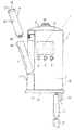
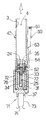
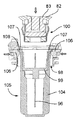
図1の符号1は、全体として、液状薬剤を注射し、特に、皮下注射を完全に自動的に行う手持ち型電子制御式注射器械を示している。
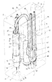
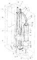
注射器械1は、実質的に、液状薬剤の入ったカートリッジ4を受け入れる受座3を備える手持ち型ハウジング2と、ハウジング2内部に収納されていて、カートリッジ4と協働し、患者に前もって設定された用量の薬剤を注射するよう選択的に作動される注射駆動ユニット5(図2及び図3)と、これまたハウジング2の内部に収納可能であり、注射駆動ユニット5の動作を制御する電子制御ユニット6(図12)、図示の例では、マイクロプロセッサとを有している。
The
具体的に説明すると、図示の例のハウジング2は、薄手の角柱の形のものであり、LCDディスプレイ8及びセットアップボタン9(その動作については後で詳細に説明する)を備えた前壁7と、後壁10と、2つの側部11,12と、患者の皮膚に接触する接触面16を備えた底壁15と、後で詳細に説明する注射開始ボタン18を備えた頂壁17とを有している。
Specifically, the
図1に示すように、ハウジング2の側部のうち一方(11)は、前壁7及び後壁10に垂直な軸線周りに底部がヒンジ止めされ、受座3内部へのカートリッジ4の挿入を可能にするよう外方へ開くドア19を有している。
As shown in FIG. 1, one side (11) of the side portions of the
図示の例では、カートリッジ4を受け入れる受座3は、底壁15及び頂壁17に垂直な軸線Aを有し、側部11の近くに形成されている。
In the illustrated example, the receiving
ハウジング2は、反対側の側部12の近くに、軸線Aに平行な軸線を有していて、注射器械1に電気的に動力を供給する1又は2つ以上のバッテリ21を受け入れる受座20(図1〜図3)を更に備え、これら電池は、底壁15に形成された別のドア22を通って挿入される。
The
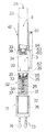
図1〜図11に示すように、カートリッジ4が、所定量の液状薬剤を収容した中空円筒形本体23により構成され、この中空円筒形本体は、市販の使い捨て針25を公知の仕方で挿入させることができる閉じられた断面の小さな端部24及び円板状の部材又はプランジャ27と流体密状態で係合する開口した反対側の端部26を有し、この円板状部材又はプランジャは、注射駆動ユニット5により作動されて本体23内部を摺動し、針25を通って薬剤を投与する。
As shown in FIGS. 1-11, the
カートリッジ4は、針25のための端部24が底壁15に向いた状態で、したがって、患者の皮膚に接触する接触面16に向いた状態でハウジング2内に挿入され、底壁15は、針25をカートリッジ4に取り付けたりこれから取り外すための軸線Aの貫通開口部30を有し、針25は、この貫通開口部を通って突き出て皮膚に注射する。
The
カートリッジ4は、ハウジング2内部のカートリッジ4の存在を確かめるため及び薬剤に関する情報、例えば組成、濃度、有効期限等を得るための公知の外部標識(図示せず)、例えば所定のパターンのバーコード、切欠き、伝導物質又は反射物質を有する。カートリッジ4を識別するために考えられるもう1つは、高周波識別システムを用いることである。
The
図4〜図6に明確に示されているように、針25は、ユーザに対する外傷を阻止するために保護用針ハウジング31に入れた状態で供給され、針ハウジング31と一緒になって針組立体32を構成する。
As clearly shown in FIGS. 4 to 6, the
具体的に説明すると、針25は、プラスチック針支持体33に固定されると共にこれから突き出ており、この針支持体は、カートリッジ4の本体23の端部24に嵌着する。
Specifically, the
公知のように、針25は、患者の皮膚を穿刺し、針支持体33から突き出ている前方部分34(図2〜図11において底部のところに示されている)と、針支持体33内に納められていて、カートリッジ4の本体23の端部24を貫通して取り付けられる後方端部35(図4〜図11では頂部のところに位置している)とを有している。具体的に説明すると、針支持体33は、針25の後方端部35を包囲していて、後で詳細に説明するようにカートリッジ4の本体23の端部24に係合する多数の弾性フランジを有している。
As is well known, the
図示していない変形例として、針支持体とカートリッジ端部との間の係合を逆に配置することも可能であり、この後者の場合、カートリッジ端部は、針支持体に係合する弾性フランジを備えるのがよい。この別の実施形態は、針支持体を特別に弾性フランジを備えるよう設計する必要はなく、標準型の市販の針組立体(更に、一般の市販のバージョンであるねじ山を備えたもの)を用いることができるという利点を有する。 As a variant not shown, the engagement between the needle support and the cartridge end can be reversed, in which case the cartridge end is elastically engaged with the needle support. A flange may be provided. This alternative embodiment does not require the needle support to be specially designed with a resilient flange, but instead of a standard commercial needle assembly (and with a common commercial version of the thread). It has the advantage that it can be used.
針ハウジング31は、針25の円筒形のカップ状本体ハウジング前方部分34により構成され、針25の開口端部は、針支持体33に装着されている。図示の例では、針組立体32は、針25の前方部分34を覆う内側針ハウジング37を更に有している。
The
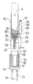
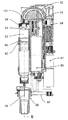
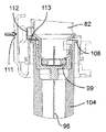
図2及び図3を参照すると、注射駆動ユニット5は、電気機械式アクチュエータ組立体40を有し、この電気機械式アクチュエータ組立体は、選択的に作動されてカートリッジ4のプランジャ27に作用してこれをカートリッジ4の本体23の内部で端部24に向かって動かして針25を通って液状薬剤を送り出すようになっている。
2 and 3, the
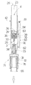
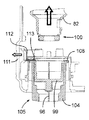
本発明の重要な特徴によれば、注射駆動ユニット5は、カートリッジ4をハウジング2の内部で軸線Aに沿って接触面16に向かって移動させたりこれから移動させて自動的に針25をカートリッジ4に装着したりこれから取り外し、又、針25を所定の速度で患者の皮膚の内部に刺入するための別の電気機械式アクチュエータ組立体41を有している。
According to an important feature of the present invention, the
具体的に説明すると、カートリッジ4は、ハウジング2の受座3の内部で軸方向に摺動する支持スリーブ42と嵌合している。
More specifically, the
図2及び図3に示すように、支持スリーブ42は、カートリッジ4の挿入を可能にするよう軸方向を互いに反対側の端部だけでなくドア19に向いた側部も開いている。
As shown in FIGS. 2 and 3, the
具体的に説明すると、支持スリーブ42は、カートリッジ4の端部24を受け入れる断面の小さな底端部38を有し、この底端部は、針25をカートリッジ4に装着すると、針支持体33の弾性フランジ36と係合する。端部38は又、支持スリーブ42の残部と共に環状肩39を構成する。
Specifically, the
アクチュエータ組立体40は、電気歯車モータ43と、カートリッジ4のプランジャ27に作用してこれをカートリッジ4の本体23の内部で端部24に向かって動かすプッシュ部材44と、歯車モータ43により生じた回転をプッシュ部材44の並進に変換する伝動装置45とを有している。
The actuator assembly 40 includes an
具体的に説明すると(図2)、伝動装置45は、実質的に、歯車モータ43の出力部材に取り付けられたピニオン46と、プッシュ部材44に連結されたねじ組立体47と、ピニオン46と噛み合う外歯及びねじ組立体47の親ねじ49に係合する内歯を備えた中間歯車48とを有している。
More specifically (FIG. 2), the
具体的に説明すると、親ねじ49は、回転するが軸方向には並進しないようハウジング2に取り付けられ、ねじ組立体47は、親ねじ49に取り付けられ、プッシュ部材44と一体であり、ハウジング2に取り付けられていて、親ねじ49に沿って並進するが、これに対して回転しないナットねじ50を更に有している。
Specifically, the lead screw 49 is attached to the
プッシュ部材44は、有利には、公知のボーデン(Bowden)型可撓性ケーブル51のコアによって構成され、このケーブルのシース52は、ハウジング2、例えば、頂壁17に固定された部分を有する。
The
アクチュエータ組立体41は、電気歯車モータ53と、カートリッジ4の支持スリーブ42と一体であり、軸線Aに平行に動くことができるスライダ54と、歯車モータ53により生じた回転をスライダ54の並進に変換する伝動装置55とを有している。
The
具体的に説明すると(図3)、スライダ54は、支持スリーブ42から側方に突き出ていて、ハウジング2に取り付けられ、軸線Aに平行な軸線に沿って並進するがこれに対して回転しないナットねじによって構成されている。伝動装置55は、歯車モータ53の出力部材に取り付けられたピニオン56と、スライダ54に連結されると共にハウジング2に取り付けられていて、それ自体の軸線回りに回転するが、この軸線に沿って並進しない親ねじ57と、ピニオン56と噛み合う外歯及び親ねじ57に係合する内歯を備えた中間歯車58とを有している。
More specifically (FIG. 3), the
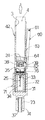
図4〜図11を参照すると、注射器械1は、ハウジング2に取り付けられた針組立体32を所定位置(図5)に保つよう受座3周りに延びる2つ又は3つ以上の保持要素60を更に有し、この所定の位置では、針組立体32は、ハウジング2の底壁15から軸線Aに沿って突き出ており、針支持体33を備えた部分は、壁15に設けられた開口部30に嵌まる。
With reference to FIGS. 4-11, the
具体的に説明すると、保持要素60は、軸線Aに平行に延びていて、ハウジング2の構造部分にヒンジ止めされた頂端部61及びロックフランジ62を備えた自由底端部を有するレバーによって構成されている。具体的に説明すると、ロックフランジ62は、開口部30のところに位置し、軸線Aに垂直に且つ開口部30の内側に延びている。
Specifically, the holding
保持要素60は、ロック形態(図5、図6、図10及び図11)を取るよう受座3の内方に弾性的に装入され、支持スリーブ42が軸線Aに沿って動くと、支持スリーブ42に設けられた異形環状突出部64と相互作用するそれぞれのカムプロフィール63によりリリース又は釈放形態(図4、図7、図8及び図9)の状態に引き離される。
The holding
具体的に説明すると、支持スリーブ42及びこれと共にカートリッジ4は、アクチュエータ組立体41により共同して軸線Aに沿って互いに逆方向に動いて次の3つの別々の位置、即ち、
−カートリッジ4が装入され、注射器械1の何らかの自動的動作(この場合、針25を組み立てたり取り外す動作や患者に薬剤を注射する動作)が開始したり終了する最上部限界位置(図4及び図7)、
−針25がカートリッジ4から抜去された最下部限界位置(図10及び図11)、
−最下部限界位置の近くにあり、液状薬剤を患者の皮膚を通って投与し、針25がカートリッジ4に連結されている動作位置(図6)
を取ることができる。
Specifically, the
The upper limit position (FIG. 4 and FIG. 4) when the
The lowest limit position (FIGS. 10 and 11) from which the
An operating position near the lowest limit position, where the liquid medicament is dispensed through the patient's skin and the
Can take.
図4〜図11に示すように、各保持要素60のカムプロフィール63及びスリーブ組立体42の突出部64は、相補形状のランプ(傾斜路)の形態をしており、相互に協働して保持部材60を支持スリーブ42の最上部限界位置で又その近くで引き離したり、支持スリーブ42の運動中、支持スリーブ42の取る他の位置では互いに離脱させて保持要素60が軸線Aに向かう弾性戻し力だけを受けさせるよう設計されている。
As shown in FIGS. 4 to 11, the
図5及び図6に示すように、ロック形態では、保持要素60のロックフランジ62は、支持スリーブ42が動作位置に動いているときに針組立体32を底壁15の開口部30の内部に保持するよう針ハウジング31の開口端部のところに形成されている外側リブ65と協働して支持スリーブ42の端部38が針支持体33の弾性フランジの内部に嵌まり、針25の後方端部35がカートリッジ4の端部24の内部に挿入されるようにする。
As shown in FIGS. 5 and 6, in the locked configuration, the locking
次に支持スリーブ42が動作位置から最上部限界位置まで動くと、依然としてロック形態にある保持要素60のロックフランジ62は、針ハウジング31に圧接してこの針ハウジングが針25を辿るのを阻止し、針支持体33及び内側針ハウジング37は、支持スリーブ42と一緒に動いて針25及び針支持体33をカートリッジ4に連結したり針ハウジング31から引き抜かれるのを自動的に行うことができるようになっている。
When the
注目されるように、保持要素60は、針ハウジング31に圧接すると、針ハウジング31をユーザに対してもロックする。かくして、最終的には、ユーザによる針ハウジング31の取り外しは、例えば、針25がカートリッジ4に連結されているときは、阻止される。
As noted, the holding
支持スリーブ42の最下部限界位置(図10及び図11)では、保持要素60のロックフランジ62は、支持スリーブ42の肩39と針支持体33の後方端部との間の隙間に入り、次に支持スリーブ42が最上部限界位置に動くと針支持体33を拘束して針25及び針支持体33が使用後にカートリッジ4から自動的に引き抜かれるようになっている。
In the lowest limit position of the support sleeve 42 (FIGS. 10 and 11), the locking
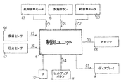
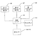
図12を参照すると、制御ユニット6は、注射器械1に設けられている種々の検出要素及びボタンから多くの信号を受け取り、制御ユニット6それ自体に格納されているプログラムに従って歯車モータ43,53及びディスプレイ8のための制御信号を出力する。
Referring to FIG. 12, the
具体的に説明すると、制御ユニット6は、次の信号を受け取る。
−受座3に向いていて、カートリッジ4の標識を検出するセンサ66(例えば、光学、電気、高周波、赤外線等)からの信号S1、
−底壁15の開口部30のところに設けられていて、開口部と所定直径の外側本体、例えば、針ハウジング31の係合を判定する存在センサ67、例えば接触設置からの信号S2、
−ハウジング2の底壁15に設けられていて、患者の皮膚との接触を判定する皮膚センサ68、例えば機械式又は容量型センサからの信号S3、
−例えば注射用量、針25が患者の皮膚を穿通する速度、薬剤送り出し速度等を選択するためのセットアップボタン9からの信号S4、
−注射開始ボタン18からの信号S5。
Specifically, the
A signal S1 from a sensor 66 (eg optical, electrical, high frequency, infrared, etc.) facing the
A
A signal S3 from a skin sensor 68 provided on the
A signal S4 from the setup button 9 for selecting, for example, the injection dose, the speed at which the
-Signal S5 from the
到来する信号に基づき、制御ユニット6は、両方の回転方向においてそれぞれの歯車モータ43,53を制御する信号C1,C2及びディスプレイ8を制御するための信号C3を出力する。
Based on the incoming signal, the
制御ユニット6は、患者及び(又は)医師にこれらのこと及びカートリッジ4内に何回分の用量が残っているかを知らせるよう制御ユニット6の動作プログラム並びに実行される注射の用量及びタイミングを格納するそれ自体の内部メモリ70(単純化のために外部に示されている)を有する。したがって、医師は、患者の同意をチェックすることができる。
The
注射器械1は、データ分析のためにコンピュータとの情報交換を可能にするインターフェイス(それ自体周知であり、図示されていない)、例えば、USBポート、ブルートゥース(Bluetooth(登録商標))通信部、赤外ポート等を更に備えている。
The
注射器械1のプラグラミングも又可能であるのがよく(例えば、コンピュータからのアップロードにより)、このプログラミングは、治験にとって有用な場合がある(例えば、或る特定の量且つ或る特定の時刻/間隔における注射のみを可能にする)。
The programming of the
例えば図4の形態の注射器械1の動作原理を説明するが、この図4の形態では、支持スリーブ42は、針25を備えておらず、最上部限界位置に設定され、カートリッジ4は、ドア19を通ってハウジング2の受座3内に挿入されると共に支持スリーブ42に連結されている。
For example, the principle of operation of the
カートリッジ4への針25の組付けは、制御ユニット6により完全に自動的に制御され、針ハウジング31の開口端部により針組立体32を単にハウジング2の底壁15の開口部30内に挿入することにより実施される。針組立体の挿入は、存在センサ67により即座に検出され、したがって、制御ユニット6は伝動装置55及びスライダ54を介して歯車モータ53を設計方向に稼働させて支持スリーブ42を動作位置に動かす。
The assembly of the
支持スリーブ42の上述の移動の結果として、突出部64は、カムプロフィール63から離されて保持要素60が開口部30の内方へ移動し、ロックフランジ62が針ハウジング31上に近づいて針ハウジングを開口部30に部分的に係合する位置にロックするようにする(図5)。
As a result of the above-described movement of the
針組立体32を手によるか図4〜図10に全体を符号71で示すアダプタを用いるかのいずれかにより開口部30の内部に挿入するのがよい。
The
具体的に説明すると、アダプタ71は、二重カップの形をしており、このアダプタは、互いに反対側の側部が開口したキャビティをそれぞれ構成していて、針ハウジング31及び内側針ハウジング37をそれぞれ収容する互いに異なる直径の互いに反対側に位置する部分72,73を有している。また、断面の大きな部分72は、針ハウジグ31のための実際の受座を構成する円筒形スリップスリーブ76を収容しており、その機能については後で説明し、断面の小さな部分73は、開口端部に近接して内部に内側リブ74を備え、この内側リブは、内側針ハウジング37に圧接してこの内側針ハウジングを針25及び針支持体33により構成された組立体から取り外す。
More specifically, the
支持スリーブ42が動作位置(図6)に達すると、端部38は、弾性フランジ36相互間に挿入されて針支持体33に連結され、針25の後方端部35は、カートリッジ4の端部24の内部に挿入される。
When the
この時点で、歯車モータ53の回転方向を逆にし、支持スリーブ42は、動作位置から最上部限界位置に動く。支持スリーブ42がこのようになると、針支持体33、針25及びこれと共に内側針ハウジング37を、保持要素60により開口部30に部分的に係合ロックされた状態で針ハウジング31から軸方向に引き抜く。
At this point, the rotational direction of the
最上部限界位置の近くでは、支持スリーブ42の突出部64は、保持要素60のカムプロフィール63と相互作用して保持要素60を引き離し、ロックフランジ62が開口部30の外方に動いて針ハウジング31を解除するようにする(図7)。
Near the uppermost limit position, the
支持スリーブ42がいったん最上部限界位置に達すると、アダプタ71の部分73を開口部30を通って受座3内に挿入するのがよく、部分73のキャビティはかくして、内側針ハウジング37と係合する。部分73の挿入は、その直径が小さいと仮定すれば、存在センサ67によっては検出されない。アダプタ71を開口部30から引き抜くと、内側針ハウジング37が針25から除去される(図8)。
Once the
実際の注射の開始の同意は、表面16が患者の皮膚に接触することにより、そして皮膚センサ68を作動させることにより与えられる。開始ボタン18を押すと、先ず最初に歯車モータ53が作動され、そして伝動装置55を介して支持スリーブ42を動作位置に戻し、針25が患者の皮膚を穿刺するようになる。次に歯車モータ43が作動され、そして電動装置45及びプッシュ部材44を介してカートリッジ4のプランジャ27に作用してこのプランジャを端部24に向かって摺動させ、所定用量の液状薬剤を送り出す。
Consent to start the actual injection is given by the
注射を行う前に、注射されるべき用量、針25が患者の皮膚を穿刺する速度、液状薬剤の送り出し速度及び注射深さを、セットアップボタン9を用いて選択してディスプレイ8上に表示するのがよい。
Before the injection, the dose to be injected, the speed at which the
注射がいったん完了すると、支持スリーブ42は、最上部限界位置に戻る。
Once the injection is complete, the
アダプタ71(図9及び図10)を用いて完全に自動的に又は例えば“SHARPS BOX”という商標名で知られている形式の針ボックス75(図11)を用いて直接に針25をカートリッジ4から抜去するのがよい。具体的に説明すると、針ハウジング31及び内側針ハウジング37(図9及び図10)を取り外すのに用いられるアダプタ71を用いる場合、先ず最初に、スリップスリーブ76を部分72から抜き取ってこれが針ハウジング31のリブ65上に軸方向に載らなければならない。
The
この時点において、針ハウジング31及び抜き取ったスリップスリーブ76の部分をハウジング2の開口部30を通って挿入して存在センサ67を作動させ、その結果、制御ユニット6が歯車モータ53を作動させて支持スリーブ42を最上部限界位置から最下部限界位置まで移動させるようにする。
At this point, the
カムプロフィール63を支持スリーブ42の突出部64から離脱させると、保持要素60は、ロックフランジ62がアダプタ71(図9)のスリップスリーブ76上に載っているのでロック形態に動くのが阻止される。
When the
しかしながら、支持スリーブ42が最下部限界位置に達すると(図10)、保持要素60のロックフランジ62は、支持スリーブ42の肩39と針支持体33の軸方向頂端部との間の隙間の中でカチッという音を出す。
However, when the
この時点で、歯車モータ53の回転方向を逆にすると、支持スリーブ42は、最上部限界位置に動く。支持スリーブ42がこのようになると、針支持体33及び針25は、これらがロックフランジ62によって保持され、かくして、支持スリーブ42及びカートリッジ4から軸方向に引き出される位置のままである。
At this point, if the rotation direction of the
支持スリーブ42が最上部限界位置に達すると、再び保持要素60を引き離し、すると、注射器械1は、いつでも次の注射のために別の針25が装着される状態にある。
When the
針ボックス75(図11)を用いる場合、開口部30の内部に位置するこの針ボックスの口側端部を単に挿入して存在センサ67を作動させると共に針25をアダプタ71に関して上述したのと全く同じ仕方でカートリッジ4から自動的に取り出す。
When using the needle box 75 (FIG. 11), the mouth end of this needle box located inside the
本発明の注射器械1の利点は、上記の説明から明らかであろう。
The advantages of the
特に、接触面16へのカートリッジ4の行き来の制御を可能にすることにより、注射器械1は、カートリッジ4への針25の取付け取出しを完全に自動的に行うことができると共に針25が患者の皮膚に穿刺する速度を制御することができる。
In particular, by allowing control of the
換言すると、実際の注射を行う場合、薬剤用量及び用量の送り出し速度だけでなく注射25をハウジング2から突き出す速度及びしたがって皮膚穿刺速度を設定することが可能である。
In other words, when performing the actual injection, it is possible to set not only the drug dose and the delivery rate of the dose, but also the speed at which the
しかしながら、特許請求の範囲に記載された本発明の範囲から逸脱することなく、本明細書において説明した注射器械1の変更を行うことができることは明らかである。
It will be apparent, however, that modifications can be made to the
特に、単一の歯車モータを用いてカートリッジ4の運動及びカートリッジ4内に入っている薬剤の送り出しを制御することができ、この単一の歯車モータは、例えば、上述したのと類似した伝動装置によって、カートリッジ4のプランジャ27に作用するボーデン型可撓性ケーブルのコアの軸方向変位を制御することができ、又、カートリッジ4のプランジャ27と本体23を選択的に互いに一体にする解除自在なロック手段を設けるのがよく、その結果、ロック手段を作動させると、カートリッジ4は、接触面16に行き来し、又、ロック手段を解除すると、プランジャ27は、カートリッジ4の本体23の内部で摺動して薬剤を送り出す。
In particular, a single gear motor can be used to control the movement of the
さらに、注射器械1を開示したのと同一の仕方で他形式の薬剤容器、例えば注射器に用いることができる。
Furthermore, it can be used in other types of drug containers, such as syringes, in the same manner as the
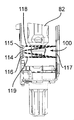
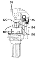
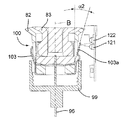
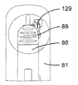
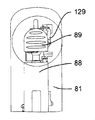
図13〜図16は、本発明の第2の実施形態の手持ち型電子制御式注射器械80を示している。第1の実施形態の注射器械1と同様、図13〜図16に示す注射器械80は、液状薬剤を収容したカートリッジ83を受け入れるカートリッジホルダ82と、カートリッジ83のプランジャ85に作用するよう設計されたプッシュ部材84と、プッシュ部材84を駆動する第1の前記機械式アクチュエータ組立体86と、特にカートリッジホルダ82を軸方向に移動させる第2の電気機械式アクチュエータ組立体87とをハウジング81(図13及び図14にのみ示されている)の中に有している。ハウジング81の側壁に設けられ、同じ側壁に設けられたスライド運動ボタン89により作動されるドア88は、これを回動軸線90回りに回転させることにより開放可能であり、それによりカートリッジ83を注射器械に出し入れすることができる。カートリッジホルダ82は、軸方向引っ込み位置にあるとき、ドア88に対して軸方向に動くことができるが、ドア88と一緒に回動軸線90回りに回転することができる。
13 to 16 show a hand-held electronically controlled
プッシュ部材84は、ばねの態をしており、注射器械の上方部分のところに設けられた案内剛性半円形ハウジング92により180°だけ片寄っている軸方向非圧縮性で且つ側方に可撓性の管91と、カートリッジホルダ82及びカートリッジ83の軸線Bに沿ってハウジング92から突き出た管91の端部に固定されているピストン93とを有している。ピストン93は、カートリッジ83のプランジャ85(図16参照)並びに可動凹み部分94(図15参照)と協働するよう設計されており、この可動凹み部分の機能については後で説明する。
図41に示された制御ユニット95の制御下において、第1のアクチュエータ組立体86は、プッシュ部材84を、ピストン93がカートリッジ83の外部に位置すると共に凹み部分94(図15)内に位置する引っ込み位置から、カートリッジ83に連結されている使い捨て針96に向かって軸方向に動かすことができ、したがって、ピストン93は、カートリッジ83内のプランジャ85と接触し、プランジャ85を押して針96(図16)を通って薬剤を送り出すようになっている。次に、プッシュ部材84をその引っ込み位置に戻すのがよく、後にはプランジャ85がこれを押した到達先の位置に位置したままになる。
Under the control of the
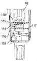
第2のアクチュエータ組立体87を制御ユニット95によって制御して第1のアクチュエータ組立体86、プッシュ部材84、プッシュ部材ハウジング92及びカートリッジホルダ82から成る構造体を軸線Bに沿って、即ち、患者の皮膚と接触可能な器械ハウジング81の底壁97に行き来させて針96をカートリッジ83に自動的に取り付けたりこれから取り外すと共に針96を患者の皮膚に刺入したり抜去するようにする。より詳細に説明すると、構造体82,84,86,92をカートリッジ83に連結されている針96が器械ハウジング81内に位置する頂部引っ込み位置と、針96が底壁97に設けられている貫通開口部98から突き出る1つ又は2つ以上の底部位置との間で動かすことができる。
The
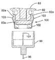
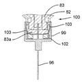
図17及び図18を参照すると、針96がプラスチック製の針支持体99に固定された状態でこれから突き出ており、この針支持体は、カートリッジホルダ82の底端部100に嵌着し、底端部100によって包囲されているカートリッジ83の対応の底端部83aが針96の後方端部101によって穿通されるようになっている。カートリッジホルダ82への針支持体99の嵌着は、カートリッジホルダ82の底端部100に固定されていて、多数の弾性フランジ103を備えた中間金属部材102によって達成され、これら弾性フランジは、カートリッジホルダ壁に設けられた溝82a内でカートリッジ83の底端部83aの外側円周方向壁と針支持体99の内側円周方向壁との間で圧縮可能である。
Referring to FIGS. 17 and 18, the
カートリッジ83への針96の連結前に、針支持体99は針96と共に保護用針ハウジング又は針キャップ104内に入れられて針96と一緒になって針組立体105(図19及び図20参照)を形成する。
Prior to connection of the
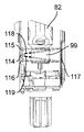
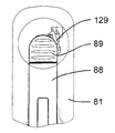
図19及び図20を参照すると、この第2の実施形態の注射器械80は、針組立体105を底壁97の開口部98内の所定の位置に保持する解除可能な保持手段を更に有する。これら解除可能な保持手段は、針組立体105を開口部98内に挿入したときに針組立体105によって作動される2つ又は3つ以上の解除可能な保持タブ又はフィンガ106と、開口部98内への針組立体105の挿入度を制限する軸方向当接面107とを有する。解除可能な保持タブ106は、開口部98の周囲に設けられ、軸線Bに差し向けられる弾性荷重を受ける。解除可能な保持タブ106は、当接面107と共に隙間を構成し、これら隙間は、針ハウジング104の環状上側フランジ108と嵌合して針組立体105を開口部98内にロックする。解除自在な保持タブ106に接続された電気機械式センサ(電気スイッチ)109(図41)は、針ハウジング104によるタブ106の作動を検出し、電気信号を制御ユニット95に送る。
Referring to FIGS. 19 and 20, the
カートリッジ83への針96の自動連結は、タブ106相互間への針組立体105の挿入によって起動される。センサ109によって即座に検出されるこの挿入により、制御ユニット95は、第2のアクチュエータ組立体87を作動させて構造体82,84,86,92を器械ハウジング81内部でその引っ込み位置から下降させる。保持タブ106により針ハウジング104に及ぼされる保持力は、針ハウジング104が図20に示すその位置にロックされたままであるようにするのに十分であり、その間、中間固定部材102を備えたカートリッジ本体82の底端部100は、針支持体99(図21)に係合する。可動構造体82,84,86,92は、カートリッジホルダ82の底端部100が針支持体99に完全に係合し、かくして針96をカートリッジ83に連結する所定の最下部位置にいったん達すると、第2のアクチュエータ組立体87は、針支持体99及び針96はカートリッジ83に連結された状態で構造体82,84,86,92をその最上部の引っ込み位置に戻し、その間、針ハウジング104は、当接面107(図22)により保持される。
Automatic connection of the
第1の実施形態の保持要素60とは異なり、保持タブ106は、ユーザがカートリッジ83への針96の連結中、針ハウジング104を取り外すのを阻止しない。しかしながら、連結中における針ハウジング104の取り外すのを阻止しない。しかしながら、連結中における針ハウジング104の取り外しは、センサ109によって検出される。かかる取り外しが生じた場合、制御ユニット95は、連結プロセスを即座に停止し、可動構造体82,84,86,92がその最上部位置に戻るのを制御する。すると、ユーザは、注射器械に設けられているディスプレイスクリーン110(図41)を介して新たな連結プロセスを開始するよう提案される。
Unlike the
針96をカートリッジ83から離脱させるため、ユーザは、空の針ハウジング104を保持手段106,107と針ハウジング104の係合が生じるまで開口部98内へ挿入する。タブ106の作動は、センサ109によって検出される。これにより、制御ユニット95は、第2のアクチュエータ組立体87を作動させて構造体82,84,86,92を針支持体99が針ハウジング104(図23及び図24)内に嵌め込まれる底部位置まで下降させる。次に、ユーザは、器械ハウジング81に設けられていて、制御ユニッ95に連結された針解除ボタン111を作動させて正方形の保持部材112を針ハウジング104の当接面107と環状上側フランジ108との間の隙間内に挿入された保持部材112の脚部113が針支持体の上端部の上方に位置する位置(24)まで軸線Bに対して横断方向に移動させるのがよい。しかる後、針支持体99及びこれと共に針96が保持部材112によって保持された状態で逆の運動を構造体82,84,86,92に及ぼし、それにより針支持体99及び針96をカートリッジホルダ82及びカートリッジ83(図25)から取り外す。次に、ユーザは、針組立体105を保持タブ106から離脱させ、この針組立体を注射器械から取り出すのがよい。
To disengage the
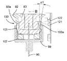
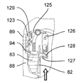
本発明の有利な特徴によれば、カートリッジ83への針96の連結を検出するセンサ手段が、注射器械に設けられている。図26〜図29に見えるこれらセンサ手段は、光送信器114、例えば、発光ダイオードと、器械ハウジング81の前壁又は後壁の内側フェースに固定された第1及び第2の光受信器115,116、例えばフォトダイオードと、器械ハウジング81の反対側の後壁又は前壁に固定された反射器117、例えばミラーとを有している。光送信器114は、軸線Bに平行な方向で第1及び第2の光受信器115,116と整列すると共にこれらの間に配置されている。カートリッジホルダ82、より正確に言えば、可動構造体82,84,86,92が引っ込み位置にあり、針がカートリッジ83(図26)に連結されていない場合、送信器114により送信されるビームの一部をなす第1の光線118は、最初に、カートリッジホルダ82の底端部100の近くを通ってミラー117によって反射され、そして2回目に底端部100の近くを通って第1の光受信器115に達し、送信器114によって送信された第2の光ビーム119は、最初に、底端部100の近くを通ってミラー117によって反射され、そして2回目に底端部100の近くを通って第2の光受信器116に達する。図27で明らかなように、カートリッジホルダ82の底端部100の上方部分の断面は、部分的に円形であるに過ぎず、即ち、底端部100は、第1の光ビーム118を通過させるよう切頭された平らな側部120を有している。針支持体99が針96と共にカートリッジホルダ82の底端部100に正しく連結されている場合、光ビーム118,119は、針支持体99によって遮られる(図29)。かくして、光受信器115,116は、もはや光ビーム118,119を受け取らない。これは、制御ユニット95により針96がカートリッジ83に正しく連結されていることを意味するものとして解釈される。図28は、針支持体99及び針96がカートリッジホルダ82及びカートリッジ83に一部だけ連結されている中間形態を示している。この形態では、第2の光ビーム119は、針支持体99によって遮られるが、第1の光ビーム118は依然として第1の光受信器115に達する。これは、制御ユニット95により、針96がカートリッジ83に一部しか連結されていないことを意味するものとして解釈される。
According to an advantageous feature of the invention, sensor means for detecting the connection of the
かくして、上述した針連結プロセス後、制御ユニット95により針がカートリッジ83に連結されていないこと又は針がカートリッジ83に一部しか連結されていないことが判定された場合、ユーザは、注射を開始させることが許されず、針連結プロセスを再開することが提案される。かくして、注射器械の使用の安全性が向上する。
Thus, after the needle connection process described above, if the
図30及び図31は、カートリッジ83への針96の連結を検出する別のセンサ手段を示している。この変形例では、中間固定部材102の弾性フランジ103のうちの一方103aは、他方よりも長い。カートリッジホルダ82が引っ込み位置にあり、針96がカートリッジ83に正しく連結されている場合、針支持体99とカートリッジ83の底端部83aとの間で圧縮されている最も長い弾性フランジ103aは、針支持体99の外部に突出した端部を有し、軸線Bと第1の角度α1をなす。この形態では、光送信器121により送信された光線は、フランジ103aの突出端部により反射されて光受信器122に差し向けられる。光受信器122による信号の受信は、制御ユニット95により、針96がカートリッジ83に正しく連結されていることを意味するものとして解釈される。他方、針96が図31に示すようにカートリッジ83に正しく連結されていなければ、フランジ103aの突出端部は、軸線Bと第1の角度α1とは異なり第2の角度α2をなす。この場合、フランジ103aの突出端部により反射された光線は、光受信器122によっては受け取られない。これは、制御ユニット95により、針がカートリッジ83に連結されておらず又は針がカートリッジ83に不適切に連結されていることを意味するものとして解釈される。
30 and 31 show another sensor means for detecting the connection of the
図15及び図16に戻ってこれらを参照すると、針96を介する薬剤の送り出しは、上述したように、プッシュ部材84のピストン93がカートリッジ83のプランジャ85を押すことにより行われる。このプロセスの間、ピストン93及び管91の一部は、カートリッジ83の中に位置する。ピストン93及び管91は、薬剤の何回分かの用量がカートリッジ83内に残っている限り、カートリッジ83内に位置したままである。カートリッジ83内に入っている薬剤の全ての用量が患者の体内にいったん注射されると、プッシュ部材84はカートリッジ83の外部に引っ込められてカートリッジの交換を可能にする(図15)。しかしながら、2回の注射相互間において、プッシュ部材84が依然としてカートリッジ83の内部に位置している状態でユーザがドア88を開いてカートリッジ83を注射器械から取り出す恐れが存在する場合がある。かかる作業は、プッシュ部材84を深刻に損傷させる場合がある。
Referring back to FIGS. 15 and 16, the medicine is sent out through the
この危険性を無くすため、本発明は有利には、プッシュ部材84がカートリッジ83の内部又は外部に位置しているとき、ドア88の開放機構体をロックし又はロック解除するロック機構体を提供する。
To eliminate this risk, the present invention advantageously provides a locking mechanism that locks or unlocks the opening mechanism of the
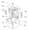
図32〜図40を参照すると、ドア88の開放機構体は、軸線Bに平行な方向に摺動可能な開放ボタン89と、器械ハウジング81内で開放ボタン89に固定されていて、フランジ124を備えたロック可能な部品123と、ロック可能な部品123により作動されるレバー125と、レバー125により作動されるロック部材126とを有している。レバー125は、器械ハウジング81に対して固定されている軸線に取り付けられている。ロック部材126は、開放ボタン89に対して軸線Bの反対側に位置した場所で可動構造体82,84,86,92に取り付けられると共に軸線Bに平行な方向に可動構造体82,84,86,92に対して摺動できるよう設けられており、このロック部材は、フランジ127を備えた凹部を有し、このフランジが、カートリッジホルタ82の対応のフランジ128と協働するよう設計されている。
Referring to FIGS. 32 to 40, the opening mechanism of the
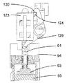
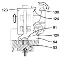
ロック機構体は、可動凹み部品94と、凹み部品94により作動され、一方の端部にフランジ130を備えたレバー129とを有し、このフランジは、ロック可能な部品123のフランジ124と協働するよう設計されている。レバー129は、器械ハウジング81に対して固定された軸線に取り付けられている。凹み部品94は、軸線Bに沿って動くことができ、ばね131(図13〜図16に見える)の一端部に固定されており、このばねの他端部は、可動構造体82,84,86,92に固定されている。
The locking mechanism has a movable
開放及びロック機構体の動作原理は次の通りである。即ち、薬剤用量の注射中(図32〜図34)、可動構造体82,84,86,92は、最下部位置にあり、プッシュ部材84のピストン93は、カートリッジ83の内部に位置し、凹み部品94は、休止位置にあって、レバー129と非接触状態にある。この形態では、第2のレバー129のフランジ130は、ロック可能な部品123のフランジ124に係合し(図33及び図34)、ロック可能な部品123及びこれと共に開放ボタン89が、ロックされ、即ち、これらを上に移動させることができないようになり、かくして、ドア88が開かれるのが阻止される。同一カートリッジ83を用いた2回の注射相互間で、可動構造体82,84,86,92は、その引っ込み位置にあり、プッシュ部材84のピストン93は、カートリッジ83の中に位置し、凹み部品94は、休止位置にあって、レバー129と非接触状態にある(図35〜図37)。この形態では、第2のレバー129のフランジ130は依然としてロック可能な部品123のフランジ124に係合し(図37)、ロック可能な部品123及びこれと共に開放ボタン89がロック状態のままであり、かくしてドア88が開かれるのが阻止されるようになっている。カートリッジ83内に入っている全ての薬剤用量がいったん注射されると、プッシャ部材84の可動構造体82,84,86,92及びピストン93は各々引っ込められる。プッシュ部材84の引っ込み中、ピストン93は、凹み部品94の凹部に入って凹み部品94をばね131の作用に抗して上方に押し、凹み部品94がフランジ124を備えた端部と反対側の第2のレバー129の端部に接触してレバー129を回転させ、かくしてレバー129をロック可能な部品123から離脱させるようになっている(図40)。次に、ドア開放ボタン89を図38に示すように上方に滑らすのがよい。開放ボタン89を上方に移動させることにより、第1のレバー125は、回転してロック部材129を下降させ、かくしてカートリッジホルダ82のフランジ128をロック部材126のフランジ127から離脱させる。次に、ばねの作用を受けてドア88及びこれと共にカートリッジホルダ82は回動軸線90回りに回転してカートリッジホルダ82からのカートリッジ83の取出しを可能にする(図38)。ドア開放ボタン89、レバー125、ロック部材126及びレバー129は、それぞれのばねの作用を受け、これらばねは、これらを図32〜図34、又は図35〜図37に示すこれらの休止位置に維持する傾向がある。
The operating principle of the opening and locking mechanism is as follows. That is, during the injection of the drug dose (FIGS. 32 to 34), the
Claims (5)
端部(83a)が針(96)に連結できる薬剤容器(83)を前記ハウジング(81)内に受け入れて保持するホルダ(82)と、
制御手段(95)と、
前記制御手段(95)によって制御され、前記薬剤容器(83)内に入れられている液状薬剤を前記針(96)を通って前記薬剤容器(83)から押し出す手段(86,84)と、を有する薬剤注射器械であって、
前記制御手段(95)に連結されていて、前記薬剤容器(83)への前記針(96)の正しい連結状態を検出する第1のセンサ手段(114〜117、103a、121,122)を有し、
前記第1のセンサ手段は、光送信器手段(114)及び第1の光受信器手段(115)を有し、前記光送信器手段(114)及び前記第1の光受信器手段(115)は、針(96)が前記薬剤容器(83)に正しく連結されていない場合、前記光送信器手段(114)により送信された第1の光線(118)が前記薬剤容器(83)及び前記ホルダ(82)によって形成されたユニットの端部(100)の近くを通って前記第1の光受信器手段(115)に到達し、前記針(96)が前記薬剤容器(83)に正しく連結されている場合、前記第1の光線(118)が前記針(96)を支持した針支持体(99)によって遮られるように配置されている
ことを特徴とする薬剤注射器械。 A housing (81);
A holder (82) for receiving and holding in said housing (81) a drug container (83) whose end (83a) can be connected to the needle (96);
Control means (95);
Means (86, 84) controlled by the control means (95) to push out the liquid medicine contained in the medicine container (83) from the medicine container (83) through the needle (96); A drug injection machine comprising:
First sensor means (114 to 117, 103a, 121, 122) connected to the control means (95) for detecting the correct connection state of the needle (96) to the medicine container (83) is provided. And
The first sensor means comprises an optical transmitter means (114) and a first optical receiver means (115), the optical transmitter means (114) and the first optical receiver means (115). If the needle (96) is not properly connected to the drug container (83), the first light beam (118) transmitted by the optical transmitter means (114) is transmitted to the drug container (83) and the holder. Passing near the end (100) of the unit formed by (82) to reach the first optical receiver means (115), the needle (96) being correctly connected to the drug container (83). The first light beam (118) is arranged to be blocked by a needle support (99) supporting the needle (96) .
端部(83a)が針(96)に連結できる薬剤容器(83)を前記ハウジング(81)内に受け入れて保持するホルダ(82)と、
制御手段(95)と、
前記制御手段(95)によって制御され、前記薬剤容器(83)内に入れられている液状薬剤を前記針(96)を通って前記薬剤容器(83)から押し出す手段(86,84)と、を有する薬剤注射器械であって、
前記制御手段(95)に連結されていて、前記薬剤容器(83)への前記針(96)の正しい連結状態を検出する第1のセンサ手段(114〜117、103a、121,122)を有し、
前記薬剤容器(83)及び前記ホルダ(82)によって形成されたユニットの端部(24,100)は、前記針(96)を支持した針支持体(99)を前記ユニット(82,83)の前記端部(100)に連結できる少なくとも1つの弾性フランジ(103)を備え、前記第1のセンサ手段は、光送信器手段(121)及び光受信器手段(122)を有し、前記光送信器手段(121)及び前記光受信器手段(122)は、前記針(96)が前記薬剤容器(83)に正しく連結されている場合、前記弾性フランジ(103)のうちの1つ(103a)の反射性部分が、前記光送信器手段(121)により送信された光線を前記光受信器手段(122)に向かって反射し、前記針(96)が前記薬剤容器(83)に正しく連結されていない場合、前記反射性部分(103a)が前記光線を前記光受信器手段(122)に一致していない方向に反射するよう配置されていることを特徴とする注射器械。 A housing (81);
A holder (82) for receiving and holding in said housing (81) a drug container (83) whose end (83a) can be connected to the needle (96);
Control means (95);
Means (86, 84) controlled by the control means (95) to push out the liquid medicine contained in the medicine container (83) from the medicine container (83) through the needle (96); A drug injection machine comprising:
First sensor means (114 to 117, 103a, 121, 122) connected to the control means (95) for detecting the correct connection state of the needle (96) to the medicine container (83) is provided. And
The end (24, 100) of the unit formed by the medicine container (83) and the holder (82) is connected to the needle support (99) supporting the needle (96) of the unit (82, 83). Comprising at least one elastic flange (103) connectable to the end (100), wherein the first sensor means comprises an optical transmitter means (121) and an optical receiver means (122); The means (121) and the optical receiver means (122) are arranged such that one of the elastic flanges (103) (103a) when the needle (96) is correctly connected to the drug container (83). The reflective portion reflects the light beam transmitted by the optical transmitter means (121) toward the optical receiver means (122), and the needle (96) is correctly connected to the drug container (83). If not Injection instrument, characterized in that said reflective portion (103a) is arranged to reflect the light beam in a direction that is not coincident with the optical receiver means (122).
Applications Claiming Priority (2)
| Application Number | Priority Date | Filing Date | Title |
|---|---|---|---|
| EP04100647.9 | 2004-02-18 | ||
| EP04100647 | 2004-02-18 |
Related Parent Applications (1)
| Application Number | Title | Priority Date | Filing Date |
|---|---|---|---|
| JP2011236462A Division JP5437343B2 (en) | 2004-02-18 | 2011-10-27 | Hand-held electronically controlled injection machine for liquid drug injection |
Publications (2)
| Publication Number | Publication Date |
|---|---|
| JP2013154253A JP2013154253A (en) | 2013-08-15 |
| JP5654635B2 true JP5654635B2 (en) | 2015-01-14 |
Family
ID=34854702
Family Applications (3)
| Application Number | Title | Priority Date | Filing Date |
|---|---|---|---|
| JP2006553594A Expired - Lifetime JP5089991B2 (en) | 2004-02-18 | 2005-02-17 | Hand-held electronically controlled injection machine for liquid drug injection |
| JP2011236462A Expired - Lifetime JP5437343B2 (en) | 2004-02-18 | 2011-10-27 | Hand-held electronically controlled injection machine for liquid drug injection |
| JP2013110198A Expired - Lifetime JP5654635B2 (en) | 2004-02-18 | 2013-05-24 | Hand-held electronically controlled injection machine for liquid drug injection |
Family Applications Before (2)
| Application Number | Title | Priority Date | Filing Date |
|---|---|---|---|
| JP2006553594A Expired - Lifetime JP5089991B2 (en) | 2004-02-18 | 2005-02-17 | Hand-held electronically controlled injection machine for liquid drug injection |
| JP2011236462A Expired - Lifetime JP5437343B2 (en) | 2004-02-18 | 2011-10-27 | Hand-held electronically controlled injection machine for liquid drug injection |
Country Status (26)
| Country | Link |
|---|---|
| US (3) | US7704231B2 (en) |
| EP (3) | EP2298391B1 (en) |
| JP (3) | JP5089991B2 (en) |
| KR (1) | KR101136115B1 (en) |
| CN (1) | CN100569307C (en) |
| AT (1) | ATE551086T1 (en) |
| AU (2) | AU2005211953B8 (en) |
| BR (2) | BR122017011640B8 (en) |
| CA (3) | CA2767913C (en) |
| CY (1) | CY1112823T1 (en) |
| DK (2) | DK2298391T3 (en) |
| EA (1) | EA009030B1 (en) |
| ES (3) | ES2555125T3 (en) |
| HR (2) | HRP20151240T1 (en) |
| HU (1) | HUE026224T2 (en) |
| IL (3) | IL177375A (en) |
| MX (1) | MXPA06009250A (en) |
| NO (2) | NO338211B1 (en) |
| NZ (1) | NZ548819A (en) |
| PL (2) | PL1715904T3 (en) |
| PT (2) | PT2298391E (en) |
| RS (1) | RS52301B (en) |
| SI (2) | SI2298391T1 (en) |
| UA (1) | UA89950C2 (en) |
| WO (1) | WO2005077441A2 (en) |
| ZA (1) | ZA200605750B (en) |
Families Citing this family (233)
| Publication number | Priority date | Publication date | Assignee | Title |
|---|---|---|---|---|
| US8034026B2 (en) * | 2001-05-18 | 2011-10-11 | Deka Products Limited Partnership | Infusion pump assembly |
| ES2555125T3 (en) * | 2004-02-18 | 2015-12-29 | Ares Trading S.A. | Manual electronically controlled injection device for injecting liquid medications |
| US7648482B2 (en) | 2004-11-22 | 2010-01-19 | Intelliject, Inc. | Devices, systems, and methods for medicament delivery |
| EP1814611A4 (en) | 2004-11-22 | 2010-06-02 | Intelliject Inc | Devices, systems, and methods for medicament delivery |
| US7648483B2 (en) | 2004-11-22 | 2010-01-19 | Intelliject, Inc. | Devices, systems and methods for medicament delivery |
| US7947017B2 (en) | 2004-11-22 | 2011-05-24 | Intelliject, Inc. | Devices, systems and methods for medicament delivery |
| US11590286B2 (en) | 2004-11-22 | 2023-02-28 | Kaleo, Inc. | Devices, systems and methods for medicament delivery |
| US10737028B2 (en) | 2004-11-22 | 2020-08-11 | Kaleo, Inc. | Devices, systems and methods for medicament delivery |
| US8206360B2 (en) | 2005-02-01 | 2012-06-26 | Intelliject, Inc. | Devices, systems and methods for medicament delivery |
| US8361026B2 (en) | 2005-02-01 | 2013-01-29 | Intelliject, Inc. | Apparatus and methods for self-administration of vaccines and other medicaments |
| GB2451769B (en) | 2005-02-01 | 2009-12-09 | Intelliject Llc | Devices, systems, and methods for medicament delivery |
| US9022980B2 (en) | 2005-02-01 | 2015-05-05 | Kaleo, Inc. | Medical injector simulation device |
| US8231573B2 (en) | 2005-02-01 | 2012-07-31 | Intelliject, Inc. | Medicament delivery device having an electronic circuit system |
| EP1690560A1 (en) | 2005-02-14 | 2006-08-16 | Ares Trading S.A. | Medication delivery device |
| DE602006019712D1 (en) * | 2005-05-10 | 2011-03-03 | Novo Nordisk As | |
| RU2432549C2 (en) | 2005-09-22 | 2011-10-27 | Ново Нордиск А/С | Method and instrument for contactless detection of absolute position and device equipped with this instrument |
| HRP20170188T1 (en) * | 2006-01-31 | 2017-04-07 | Ares Trading S.A. | INJECTION DEVICE WITH CAPACITIVE NEARBY SENSOR |
| JP4802737B2 (en) * | 2006-01-31 | 2011-10-26 | パナソニック株式会社 | Chemical solution administration device and control method thereof |
| AU2011218649B8 (en) * | 2006-03-29 | 2015-11-19 | Kaleo, Inc. | Devices, systems and methods for medicament delivery |
| JP2009534080A (en) * | 2006-04-20 | 2009-09-24 | アレス トレーディング ソシエテ アノニム | Method for marking pharmaceutical articles |
| US7811252B2 (en) | 2006-05-17 | 2010-10-12 | Alcon Research, Ltd. | Dosage control device |
| WO2008091838A2 (en) | 2007-01-22 | 2008-07-31 | Intelliject, Inc. | Medical injector with compliance tracking and monitoring |
| US8480653B2 (en) | 2007-05-23 | 2013-07-09 | Biosense Webster, Inc. | Magnetically guided catheter with concentric needle port |
| US8603046B2 (en) * | 2007-05-23 | 2013-12-10 | Biosense Webster, Inc. | Automated injection catheter device and system |
| US8192399B2 (en) | 2007-05-23 | 2012-06-05 | Biosense Webster, Inc. | Extension control handle with adjustable locking mechanism |
| US9205193B2 (en) * | 2007-06-12 | 2015-12-08 | Peter V. Boesen | Self-contained medication injection system and method |
| US7740612B2 (en) | 2007-07-27 | 2010-06-22 | Milestone Scientific, Inc | Self-administration injection system |
| US9173997B2 (en) | 2007-10-02 | 2015-11-03 | Medimop Medical Projects Ltd. | External drug pump |
| US9656019B2 (en) | 2007-10-02 | 2017-05-23 | Medimop Medical Projects Ltd. | Apparatuses for securing components of a drug delivery system during transport and methods of using same |
| US7967795B1 (en) | 2010-01-19 | 2011-06-28 | Lamodel Ltd. | Cartridge interface assembly with driving plunger |
| US9345836B2 (en) | 2007-10-02 | 2016-05-24 | Medimop Medical Projects Ltd. | Disengagement resistant telescoping assembly and unidirectional method of assembly for such |
| US10420880B2 (en) | 2007-10-02 | 2019-09-24 | West Pharma. Services IL, Ltd. | Key for securing components of a drug delivery system during assembly and/or transport and methods of using same |
| DE102007054868A1 (en) * | 2007-11-07 | 2009-05-20 | Arzneimittel Gmbh Apotheker Vetter & Co. Ravensburg | Device and method for mounting a pharmaceutical application aid |
| EP2113268A1 (en) | 2008-04-30 | 2009-11-04 | F. Hoffmann-Roche AG | Administering device with safety features |
| USD994111S1 (en) | 2008-05-12 | 2023-08-01 | Kaleo, Inc. | Medicament delivery device cover |
| US9974904B2 (en) | 2008-05-20 | 2018-05-22 | Avant Medical Corp. | Autoinjector system |
| US8177749B2 (en) * | 2008-05-20 | 2012-05-15 | Avant Medical Corp. | Cassette for a hidden injection needle |
| US8052645B2 (en) * | 2008-07-23 | 2011-11-08 | Avant Medical Corp. | System and method for an injection using a syringe needle |
| AU2009290976B2 (en) * | 2008-09-10 | 2015-05-28 | F. Hoffmann-La Roche Ag | Delivery device for use with a therapeutic drug |
| US9393369B2 (en) | 2008-09-15 | 2016-07-19 | Medimop Medical Projects Ltd. | Stabilized pen injector |
| US12097357B2 (en) | 2008-09-15 | 2024-09-24 | West Pharma. Services IL, Ltd. | Stabilized pen injector |
| EP3545987B1 (en) | 2008-09-18 | 2021-02-17 | Becton, Dickinson and Company | Medical injector with coupled body portions |
| AU2009312474B2 (en) | 2008-11-07 | 2014-12-04 | Insuline Medical Ltd. | Device and method for drug delivery |
| EP2361647B8 (en) | 2008-12-22 | 2018-06-27 | PHC Holdings Corporation | Medicament dispensing device |
| EP2393533B1 (en) * | 2009-02-05 | 2015-03-25 | Sanofi-Aventis Deutschland GmbH | Medicament delivery devices |
| RU2524122C2 (en) * | 2009-02-05 | 2014-07-27 | Санофи-Авентис Дойчланд Гмбх | Devices for medication introduction |
| EP2238999A1 (en) | 2009-04-02 | 2010-10-13 | Vincent Pongpairochana | Automatic injection device |
| CN101987220B (en) * | 2009-07-30 | 2013-11-13 | 德昌电机(深圳)有限公司 | Needle driving assembly for medical instrument |
| US8157769B2 (en) | 2009-09-15 | 2012-04-17 | Medimop Medical Projects Ltd. | Cartridge insertion assembly for drug delivery system |
| US10071196B2 (en) | 2012-05-15 | 2018-09-11 | West Pharma. Services IL, Ltd. | Method for selectively powering a battery-operated drug-delivery device and device therefor |
| US10071198B2 (en) | 2012-11-02 | 2018-09-11 | West Pharma. Servicees IL, Ltd. | Adhesive structure for medical device |
| USD810279S1 (en) | 2009-09-15 | 2018-02-13 | Medimop Medical Projects Ltd. | Injector device |
| US8864718B2 (en) | 2009-10-23 | 2014-10-21 | Bang & Olufsen Medicom A/S | Auto injector with automatic needle shielding |
| US8945066B2 (en) | 2009-11-06 | 2015-02-03 | Crisi Medical Systems, Inc. | Medication injection site and data collection system |
| US10226586B2 (en) | 2011-05-26 | 2019-03-12 | Pourang Bral | Means and method to painlessly puncture skin |
| US8657783B2 (en) * | 2010-11-08 | 2014-02-25 | DentistInJerseyCity.net | Injectable solution container and syringe |
| US10973994B2 (en) | 2013-09-16 | 2021-04-13 | Pourang Bral | Means and method to invade skin, mucosa, and underlying tissues with little or no pain |
| US9770560B2 (en) | 2009-11-12 | 2017-09-26 | Pourang Bral | Means and method to administer injections with little or no pain |
| EP2335755A1 (en) * | 2009-12-17 | 2011-06-22 | Sanofi-Aventis Deutschland GmbH | Device and method for delivery of two or more drug agents |
| US8348898B2 (en) | 2010-01-19 | 2013-01-08 | Medimop Medical Projects Ltd. | Automatic needle for drug pump |
| CN102740909B (en) * | 2010-02-01 | 2016-05-04 | 赛诺菲-安万特德国有限公司 | Cartridge holder, drug delivery device and method for securing a cartridge in a cartridge holder |
| JP5671730B2 (en) * | 2010-03-01 | 2015-02-18 | パナソニックヘルスケアホールディングス株式会社 | Drug administration device |
| US9101534B2 (en) | 2010-04-27 | 2015-08-11 | Crisi Medical Systems, Inc. | Medication and identification information transfer apparatus |
| US9452261B2 (en) | 2010-05-10 | 2016-09-27 | Medimop Medical Projects Ltd. | Low volume accurate injector |
| US10492991B2 (en) | 2010-05-30 | 2019-12-03 | Crisi Medical Systems, Inc. | Medication container encoding, verification, and identification |
| US9514131B1 (en) | 2010-05-30 | 2016-12-06 | Crisi Medical Systems, Inc. | Medication container encoding, verification, and identification |
| US8740847B2 (en) * | 2010-06-09 | 2014-06-03 | Valeritas, Inc. | Fluid delivery device needle retraction mechanisms, cartridges and expandable hydraulic fluid seals |
| US8206340B2 (en) * | 2010-08-18 | 2012-06-26 | Thuban, Inc. | Integrated glucose monitor and insulin injection pen with automatic emergency notification |
| CA2808469A1 (en) * | 2010-08-19 | 2012-02-23 | Sanofi-Aventis Deutschland Gmbh | Method and system for determining information related to a drug reservoir using an electronic sensor |
| US10143796B2 (en) | 2010-08-25 | 2018-12-04 | Medtronic, Inc. | Fluid delivery device refill access |
| US9737660B2 (en) * | 2010-08-25 | 2017-08-22 | Medtronic, Inc. | Drug infusion device with controllable valve |
| WO2012025590A2 (en) * | 2010-08-26 | 2012-03-01 | Sanofi-Aventis Deutschland Gmbh | Method and system for determining information related to a drug reservoir |
| WO2012025639A1 (en) * | 2010-08-27 | 2012-03-01 | Novo Nordisk A/S | Medical injection device |
| JP5952741B2 (en) * | 2010-11-18 | 2016-07-13 | パナソニックヘルスケアホールディングス株式会社 | Drug injection device |
| CA2821943A1 (en) | 2010-12-22 | 2012-06-28 | Sanofi-Aventis Deutschland Gmbh | Dedicated cartridge |
| US8627816B2 (en) | 2011-02-28 | 2014-01-14 | Intelliject, Inc. | Medicament delivery device for administration of opioid antagonists including formulations for naloxone |
| US8939943B2 (en) | 2011-01-26 | 2015-01-27 | Kaleo, Inc. | Medicament delivery device for administration of opioid antagonists including formulations for naloxone |
| US9084849B2 (en) | 2011-01-26 | 2015-07-21 | Kaleo, Inc. | Medicament delivery devices for administration of a medicament within a prefilled syringe |
| USD702834S1 (en) | 2011-03-22 | 2014-04-15 | Medimop Medical Projects Ltd. | Cartridge for use in injection device |
| WO2012130901A1 (en) * | 2011-03-30 | 2012-10-04 | Sanofi-Aventis Deutschland Gmbh | Injection device |
| HUE042822T2 (en) * | 2011-04-20 | 2019-07-29 | Amgen Inc | Automatic injection device |
| WO2012160167A1 (en) * | 2011-05-25 | 2012-11-29 | Sanofi-Aventis Deutschland Gmbh | Use of switches to facilitate a safe and convenient attachment and removal procedure |
| JP6335779B2 (en) * | 2011-05-25 | 2018-05-30 | サノフィ−アベンティス・ドイチュラント・ゲゼルシャフト・ミット・ベシュレンクテル・ハフツング | Drug delivery device having a cartridge sensor and a cartridge holder door sensor and method for controlling the device |
| JP6050331B2 (en) * | 2011-05-25 | 2016-12-21 | サノフィ−アベンティス・ドイチュラント・ゲゼルシャフト・ミット・ベシュレンクテル・ハフツング | Drug delivery device with medication interface sensor and method for controlling the device |
| TR201808306T4 (en) * | 2011-05-25 | 2018-07-23 | Sanofi Aventis Deutschland | A cartridge holder, a medical device comprising such a cartridge holder, and a method for inserting a medical drug reservoir. |
| US9078809B2 (en) | 2011-06-16 | 2015-07-14 | Crisi Medical Systems, Inc. | Medication dose preparation and transfer system |
| US8333716B1 (en) | 2011-06-21 | 2012-12-18 | Yofimeter, Llc | Methods for using an analyte testing device |
| US20130085349A1 (en) | 2011-06-21 | 2013-04-04 | Yofimeter, Llc | Analyte testing devices |
| US10293107B2 (en) | 2011-06-22 | 2019-05-21 | Crisi Medical Systems, Inc. | Selectively Controlling fluid flow through a fluid pathway |
| US9744298B2 (en) | 2011-06-22 | 2017-08-29 | Crisi Medical Systems, Inc. | Selectively controlling fluid flow through a fluid pathway |
| RU2605151C2 (en) * | 2011-07-18 | 2016-12-20 | Либэль-Фларшайм Кампани ЭлЭлСи | Injection system with capacitive measurement |
| US9205024B1 (en) | 2011-09-23 | 2015-12-08 | Joram O. Mogaka | Intravenous medication delivery safety assembly |
| TW201345578A (en) * | 2012-01-31 | 2013-11-16 | Sanofi Aventis Deutschland | Limiting life time of dispense assembly |
| EP2809375B1 (en) | 2012-01-31 | 2021-08-11 | Medimop Medical Projects Ltd. | Time dependent drug delivery apparatus |
| US10052435B2 (en) * | 2012-01-31 | 2018-08-21 | Precifiex SA | Skin-attachable miniature drug injection device with remote activation capability and dry drug carrier within injection needle |
| WO2013141351A1 (en) * | 2012-03-22 | 2013-09-26 | テルモ株式会社 | Automatic injection device |
| US10668213B2 (en) | 2012-03-26 | 2020-06-02 | West Pharma. Services IL, Ltd. | Motion activated mechanisms for a drug delivery device |
| US9072827B2 (en) | 2012-03-26 | 2015-07-07 | Medimop Medical Projects Ltd. | Fail safe point protector for needle safety flap |
| US9463280B2 (en) | 2012-03-26 | 2016-10-11 | Medimop Medical Projects Ltd. | Motion activated septum puncturing drug delivery device |
| US10748449B2 (en) | 2012-04-04 | 2020-08-18 | Noble International, Inc. | Medicament delivery training device |
| USD808010S1 (en) | 2012-04-20 | 2018-01-16 | Amgen Inc. | Injection device |
| USD898908S1 (en) | 2012-04-20 | 2020-10-13 | Amgen Inc. | Pharmaceutical product cassette for an injection device |
| KR101368920B1 (en) * | 2012-04-30 | 2014-02-28 | 방시열 | An injetion device |
| US9522235B2 (en) | 2012-05-22 | 2016-12-20 | Kaleo, Inc. | Devices and methods for delivering medicaments from a multi-chamber container |
| EP2862588B1 (en) | 2012-06-13 | 2018-09-19 | PHC Holdings Corporation | Drug injection device |
| EP2674179A1 (en) | 2012-06-15 | 2013-12-18 | Ares Trading S.A. | Injection device |
| EP2674184A1 (en) | 2012-06-15 | 2013-12-18 | Ares Trading S.A. | Injection device with needle sensor |
| EP2674180A1 (en) * | 2012-06-15 | 2013-12-18 | Ares Trading S.A. | Injection device |
| HK1209072A1 (en) | 2012-07-05 | 2016-03-24 | Unitract Syringe Pty Ltd | Automatic injectors for injectable cartridges and drive control mechanisms therefor |
| EP2698180A1 (en) * | 2012-08-15 | 2014-02-19 | Sanofi-Aventis Deutschland GmbH | Autoinjector |
| EP2892590B1 (en) * | 2012-09-05 | 2018-01-10 | E3D Agricultural Cooperative Association Ltd. | Electronic auto-injection device |
| JP2015531258A (en) * | 2012-09-11 | 2015-11-02 | サノフィ−アベンティス・ドイチュラント・ゲゼルシャフト・ミット・ベシュレンクテル・ハフツング | Drive mechanism for drug delivery device and drug delivery device |
| US10318915B2 (en) | 2012-09-26 | 2019-06-11 | Thuban, Inc. | Healthcare system for recording and monitoring transactions of system participants |
| CA2808738C (en) * | 2012-09-26 | 2014-03-18 | Gadlight, Inc | Portable medicine injection device and metering system |
| EP2716317A1 (en) * | 2012-10-04 | 2014-04-09 | Sanofi-Aventis Deutschland GmbH | Medicament delivery device with trigger button |
| US9179260B2 (en) | 2012-12-03 | 2015-11-03 | Mylan Inc. | Medicament information system and method |
| US9692829B2 (en) | 2012-12-03 | 2017-06-27 | Mylan Inc. | Medication delivery system and method |
| US20140155827A1 (en) | 2012-12-03 | 2014-06-05 | Mylan, Inc. | Medicament information system and method |
| US9643770B2 (en) | 2012-12-03 | 2017-05-09 | Mylan Inc. | System and method for medicament storage, dispensing, and administration |
| JP6240090B2 (en) * | 2012-12-13 | 2017-11-29 | パナソニックヘルスケアホールディングス株式会社 | Drug injection device |
| US9421323B2 (en) * | 2013-01-03 | 2016-08-23 | Medimop Medical Projects Ltd. | Door and doorstop for portable one use drug delivery apparatus |
| JP6356698B2 (en) * | 2013-01-29 | 2018-07-11 | サノフィ−アベンティス・ドイチュラント・ゲゼルシャフト・ミット・ベシュレンクテル・ハフツング | Drug delivery device |
| DK2950851T3 (en) * | 2013-01-29 | 2017-05-01 | Sanofi Aventis Deutschland | Drug delivery device |
| US9357961B2 (en) | 2013-02-22 | 2016-06-07 | Thuban, Inc. | Device for enabling patient self testing and treatment self- administration and system using the device for managing the patient's health care |
| US10143830B2 (en) | 2013-03-13 | 2018-12-04 | Crisi Medical Systems, Inc. | Injection site information cap |
| JP6336564B2 (en) | 2013-03-15 | 2018-06-06 | アムゲン・インコーポレーテッド | Drug cassette, auto-injector, and auto-injector system |
| TWI614041B (en) | 2013-03-15 | 2018-02-11 | 安美基公司 | Cassette for an injector |
| US20140276413A1 (en) | 2013-03-15 | 2014-09-18 | Jeff Baker | Medicament delivery and simulation system with a removable disposable container for medicament and a rotatable actuation component |
| EP2978471B1 (en) | 2013-03-25 | 2017-04-19 | Carebay Europe Ltd. | Medicament delivery device comprising a locking mechanism |
| US9011164B2 (en) | 2013-04-30 | 2015-04-21 | Medimop Medical Projects Ltd. | Clip contact for easy installation of printed circuit board PCB |
| US9889256B2 (en) | 2013-05-03 | 2018-02-13 | Medimop Medical Projects Ltd. | Sensing a status of an infuser based on sensing motor control and power input |
| EP2818191A1 (en) * | 2013-06-25 | 2014-12-31 | F. Hoffmann-La Roche AG | Einführinstrument mit Parametereinstellung |
| TR201905369T4 (en) * | 2013-08-05 | 2019-05-21 | Sanofi Aventis Deutschland | Cap bending tool for an apparatus. |
| CA2920835A1 (en) | 2013-08-20 | 2015-02-26 | Anutra Medical, Inc. | Syringe fill system and method |
| TR201905952T4 (en) * | 2013-09-05 | 2019-05-21 | Sanofi Aventis Deutschland | Drive mechanism for a needle insertion assembly. |
| AU2014338867A1 (en) | 2013-10-25 | 2016-05-19 | Ares Trading S.A. | Patient care system reporting adherence to treatment regimen |
| US10080848B2 (en) | 2013-11-12 | 2018-09-25 | Novo Nordisk A/S | Drug delivery device with movable needle mount |
| EP2894581A1 (en) | 2014-01-13 | 2015-07-15 | Ares Trading S.A. | Medical device connection station |
| EP2894540A1 (en) | 2014-01-13 | 2015-07-15 | Ares Trading S.A. | Medical device connection station |
| US10729851B2 (en) | 2013-12-27 | 2020-08-04 | Phc Holdings Corporation | Pharmaceutical injection device |
| CN106232170B (en) * | 2014-02-17 | 2022-07-29 | 诺博国际公司 | System and method for detecting and preventing wet injection |
| US10034976B2 (en) | 2014-03-24 | 2018-07-31 | Medtronic Minimed, Inc. | Fluid infusion patch pump device with automatic fluid system priming feature |
| EP3145563B1 (en) | 2014-03-26 | 2019-11-27 | Sanofi | Assembly for a drug delivery device |
| EP3127569B1 (en) | 2014-04-01 | 2018-06-13 | PHC Holdings Corporation | Pharmaceutical injection device, display control method for pharmaceutical injecting device, and injection site display device |
| JP6261725B2 (en) * | 2014-04-25 | 2018-01-17 | パナソニックヘルスケアホールディングス株式会社 | Drug injection device |
| CN111840696B (en) | 2014-06-03 | 2022-12-20 | 安姆根有限公司 | Controllable drug delivery systems and methods of use |
| USD774182S1 (en) | 2014-06-06 | 2016-12-13 | Anutra Medical, Inc. | Anesthetic delivery device |
| USD763433S1 (en) * | 2014-06-06 | 2016-08-09 | Anutra Medical, Inc. | Delivery system cassette |
| US9919111B2 (en) | 2014-06-30 | 2018-03-20 | Elwha Llc | Active lubrication of penetrating devices |
| US9919112B2 (en) | 2014-06-30 | 2018-03-20 | Elwha Llc | Active lubrication of penetrating devices |
| US9517307B2 (en) | 2014-07-18 | 2016-12-13 | Kaleo, Inc. | Devices and methods for delivering opioid antagonists including formulations for naloxone |
| TWI689326B (en) * | 2014-08-06 | 2020-04-01 | 加拿大商複製細胞生命科學公司 | Injection device |
| US9919096B2 (en) | 2014-08-26 | 2018-03-20 | Bigfoot Biomedical, Inc. | Infusion pump system and method |
| US11478583B2 (en) | 2014-10-03 | 2022-10-25 | Enable Injections, Inc. | Medical fluid transfer and injection apparatus and method |
| ES2948459T3 (en) | 2014-10-10 | 2023-09-12 | Becton Dickinson Co | Syringe labeling device |
| US9505233B2 (en) | 2014-10-10 | 2016-11-29 | Becton, Dickinson And Company | Tensioning control device |
| US9795534B2 (en) | 2015-03-04 | 2017-10-24 | Medimop Medical Projects Ltd. | Compliant coupling assembly for cartridge coupling of a drug delivery device |
| US10251813B2 (en) | 2015-03-04 | 2019-04-09 | West Pharma. Services IL, Ltd. | Flexibly mounted cartridge alignment collar for drug delivery device |
| CN107635527B (en) | 2015-03-10 | 2021-04-23 | 里珍纳龙药品有限公司 | Sterile Piercing Systems and Methods |
| CN104689462A (en) * | 2015-03-12 | 2015-06-10 | 侯强 | Burn drug applicator |
| JP6684820B2 (en) | 2015-03-24 | 2020-04-22 | アレス トレーディング ソシエテ アノニム | Patient care system |
| WO2016154427A2 (en) | 2015-03-24 | 2016-09-29 | Kaleo, Inc. | Devices and methods for delivering a lyophilized medicament |
| US9744297B2 (en) | 2015-04-10 | 2017-08-29 | Medimop Medical Projects Ltd. | Needle cannula position as an input to operational control of an injection device |
| US10293120B2 (en) | 2015-04-10 | 2019-05-21 | West Pharma. Services IL, Ltd. | Redundant injection device status indication |
| US20160331899A1 (en) * | 2015-05-13 | 2016-11-17 | Alps South, LLC | Syringe actuator system for delivering toxic medical compositions |
| US10149943B2 (en) | 2015-05-29 | 2018-12-11 | West Pharma. Services IL, Ltd. | Linear rotation stabilizer for a telescoping syringe stopper driverdriving assembly |
| CN113181477B (en) | 2015-06-04 | 2023-07-14 | 麦迪麦珀医疗工程有限公司 | Cartridge insertion for drug delivery device |
| US11160929B2 (en) | 2015-06-26 | 2021-11-02 | Quio Technologies Llc | Auto-injector device with interchangeable modules for dimensional and operational compatibility with a variety of diverse pre-filled cartridges |
| US10576206B2 (en) | 2015-06-30 | 2020-03-03 | Kaleo, Inc. | Auto-injectors for administration of a medicament within a prefilled syringe |
| US10576207B2 (en) | 2015-10-09 | 2020-03-03 | West Pharma. Services IL, Ltd. | Angled syringe patch injector |
| US9987432B2 (en) | 2015-09-22 | 2018-06-05 | West Pharma. Services IL, Ltd. | Rotation resistant friction adapter for plunger driver of drug delivery device |
| JP7044708B2 (en) | 2015-10-09 | 2022-03-30 | ウェスト ファーマ サービシーズ イスラエル リミテッド | How to fill a customized syringe |
| CN105148357B (en) * | 2015-10-30 | 2018-05-11 | 东北师范大学 | A kind of anti-compaction novopen |
| US11033683B2 (en) * | 2015-11-27 | 2021-06-15 | Sanofi-Aventis Deutschland Gmbh | Medicament injection device |
| US10881801B2 (en) | 2015-12-24 | 2021-01-05 | Phc Holdings Corporation | Drug infusion device, cartridge adapter, and drug infusion system |
| US10894129B2 (en) | 2015-12-24 | 2021-01-19 | Phc Holdings Corporation | Drug injection device, cartridge adapter, and drug injection system |
| CN109219456B (en) | 2016-01-21 | 2020-05-15 | 西医药服务以色列有限公司 | Force containment in autoinjectors |
| CN113041432B (en) | 2016-01-21 | 2023-04-07 | 西医药服务以色列有限公司 | Medicament delivery device comprising a visual indicator |
| WO2017127215A1 (en) | 2016-01-21 | 2017-07-27 | Medimop Medical Projects Ltd. | Needle insertion and retraction mechanism |
| US11389597B2 (en) | 2016-03-16 | 2022-07-19 | West Pharma. Services IL, Ltd. | Staged telescopic screw assembly having different visual indicators |
| RS65082B1 (en) * | 2016-03-21 | 2024-02-29 | Lilly Co Eli | Medical delivery device with axially expandable drive member |
| US9694145B1 (en) * | 2016-03-29 | 2017-07-04 | Joseph Onorato | Auto-injector systems and method for delivering cyst medication on demand |
| GB2550924A (en) * | 2016-05-31 | 2017-12-06 | Ndm Technologies Ltd | Improvements in or relating to transdermal delivery |
| US11103652B2 (en) | 2016-06-02 | 2021-08-31 | West Pharma. Services IL, Ltd. | Three position needle retraction |
| GB2606087B (en) * | 2016-06-06 | 2023-03-08 | E3D Agricultural Cooporative Association Ltd | Multiple use computerized injector |
| CN109862928B (en) * | 2016-07-29 | 2022-06-14 | 亚克安娜治疗学有限公司 | Automated drug delivery systems and methods |
| US11730892B2 (en) | 2016-08-01 | 2023-08-22 | West Pharma. Services IL, Ltd. | Partial door closure prevention spring |
| US10653829B2 (en) | 2016-08-01 | 2020-05-19 | West Pharma. Services IL, Ltd. | Automatic injector having door block until proper cartridge insertion |
| US11338090B2 (en) | 2016-08-01 | 2022-05-24 | West Pharma. Services IL, Ltd. | Anti-rotation cartridge pin |
| RU2649504C1 (en) * | 2016-10-10 | 2018-04-03 | Сергей Валентинович Таранов | Automatic injector for standard medical syringes |
| US20180110925A1 (en) * | 2016-10-21 | 2018-04-26 | Summit Street Medical LLC | Drug delivery |
| WO2018080959A1 (en) | 2016-10-31 | 2018-05-03 | Summit Street Medical LLC | Wearable drug delivery device |
| EP3558420B1 (en) | 2016-12-23 | 2024-09-18 | Kaleo, Inc. | Medicament delivery device and methods for delivering drugs to infants and children |
| EP3570909B1 (en) | 2017-01-17 | 2024-06-26 | West Pharma. Services Il, Ltd. | Bent spring powered injector |
| EP3596637B1 (en) | 2017-03-15 | 2024-09-18 | Novartis AG | Medical device, programming device, wireless terminal, and medical system |
| KR20190128052A (en) | 2017-03-15 | 2019-11-14 | 노바르티스 아게 | System for the use of pharmaceutical products |
| KR20190131024A (en) | 2017-03-15 | 2019-11-25 | 노바르티스 아게 | System for administering pharmaceutical |
| WO2018166703A1 (en) * | 2017-03-16 | 2018-09-20 | Novartis Ag | Needle ejection and retraction mechanism and injector device |
| CA3053681A1 (en) * | 2017-03-16 | 2018-09-20 | Novartis Ag | Injector device |
| CN110545864A (en) * | 2017-03-16 | 2019-12-06 | 诺瓦提斯公司 | Needle ejecting and retracting mechanism and injection device |
| EP3595738A1 (en) * | 2017-03-16 | 2020-01-22 | Novartis AG | Injector device |
| IL308643B2 (en) | 2017-05-05 | 2025-02-01 | Regeneron Pharma | Automatic injector |
| ES2976557T3 (en) * | 2017-05-25 | 2024-08-05 | Enable Injections Inc | Apparatus and method for injection and transfer of medical fluids with compliance monitoring |
| EP3630226B1 (en) | 2017-05-30 | 2025-10-22 | West Pharma. Services Il, Ltd. | Modular drive train for wearable injector |
| CN111201051B (en) | 2017-08-10 | 2022-04-01 | 西医药服务以色列有限公司 | Locking mechanism for injector medicine barrel door |
| JP6840891B2 (en) * | 2017-08-10 | 2021-03-10 | ウェスト ファーマ サービシーズ イスラエル リミテッド | Syringe self-test and corresponding syringe door unlocking mechanism |
| JP7370969B2 (en) * | 2017-11-16 | 2023-10-30 | アムジエン・インコーポレーテツド | Door latch mechanism for drug delivery devices |
| KR102508085B1 (en) | 2017-12-08 | 2023-03-13 | 일라이 릴리 앤드 캄파니 | Medical delivery device with axially expandable drive ribbon |
| JP7402799B2 (en) | 2017-12-22 | 2023-12-21 | ウェスト ファーマ サービシーズ イスラエル リミテッド | Syringes available with different cartridge sizes |
| MX2020008788A (en) | 2018-02-22 | 2020-10-14 | Ares Trading Sa | Storage container for electronic injection device. |
| EP3530303B1 (en) | 2018-02-22 | 2024-07-17 | Ares Trading S.A. | Storage container for electronic injection device |
| KR102037471B1 (en) * | 2018-04-03 | 2019-10-28 | 진세훈 | Automated rejuvenation apparatus for wrinkle of skin |
| USD893715S1 (en) | 2018-11-06 | 2020-08-18 | Joseph Onorato | Measurement guide for a cyst, lesion or skin disorder |
| EP3666314A1 (en) * | 2018-12-10 | 2020-06-17 | Ares Trading S.A. | Injection device |
| EP3902584A4 (en) | 2018-12-29 | 2022-09-07 | Kaleo, Inc. | DEVICES AND METHODS FOR DELIVERING SUBSTANCES IN A PRE-FILLED SYRINGE |
| ES3063158T3 (en) | 2019-02-08 | 2026-04-15 | Tracker Syringe Llc | Needle sensor assembly and method of use of same |
| CA3145580A1 (en) | 2019-08-09 | 2021-02-18 | Kaleo, Inc. | Devices and methods for delivery of substances within a prefilled syringe |
| CN110665094B (en) * | 2019-09-29 | 2025-05-30 | 无锡鸿羽医疗科技有限公司 | A fully automatic electronic insulin injection pen |
| CN110575588B (en) * | 2019-09-29 | 2024-12-31 | 无锡鸿羽医疗科技有限公司 | A safety device for the drug storage bin of a fully automatic insulin injection pen |
| CN111481816B (en) * | 2020-05-07 | 2022-08-16 | 泰兴市致远知识产权服务有限公司 | Positioning and disinfecting device used before dermatology operation |
| WO2021250536A1 (en) * | 2020-06-08 | 2021-12-16 | Applimind Ltd. | Application of hair-coloring compositions |
| US12268847B1 (en) | 2021-02-10 | 2025-04-08 | Kaleo, Inc. | Devices and methods for delivery of substances within a medicament container |
| CN113509637A (en) * | 2021-05-08 | 2021-10-19 | 上海曦鹏工贸有限公司 | Beauty gun control method, system, electronic device and storage medium |
| CN113615622B (en) * | 2021-07-07 | 2022-06-17 | 浙江省海洋水产研究所 | Experimental device for be used for cultivateing benthos |
| WO2023084090A1 (en) * | 2021-11-15 | 2023-05-19 | Fundació Hospital Universitari Vall D'hebron - Institut De Recerca | Syringe driving systems |
| USD1007676S1 (en) | 2021-11-16 | 2023-12-12 | Regeneron Pharmaceuticals, Inc. | Wearable autoinjector |
| CN114470403A (en) * | 2021-12-31 | 2022-05-13 | 深圳瑞宇医疗科技有限公司 | Intelligent injection device capable of being pasted on skin and automatically injecting insulin |
| EP4606406A3 (en) | 2022-05-16 | 2025-09-10 | Pfizer Inc. | Injection device with a needle detection feature |
| EP4727618A1 (en) * | 2023-06-16 | 2026-04-22 | Janssen Biotech, Inc. | Drug delivery device |
| EP4727617A1 (en) * | 2023-06-16 | 2026-04-22 | Janssen Biotech, Inc. | Drug delivery device |
| CN118142026A (en) * | 2024-03-11 | 2024-06-07 | 祥辉耀国(苏州)科技有限公司 | Pen type full-automatic precise injection system |
| CN119499523B (en) * | 2024-10-21 | 2025-10-14 | 山东同齐医学科技有限公司 | A cavity injection device |
| CN120459456A (en) * | 2025-07-04 | 2025-08-12 | 中国人民解放军空军军医大学 | A portable emergency drug storage and injection device |
Family Cites Families (117)
| Publication number | Priority date | Publication date | Assignee | Title |
|---|---|---|---|---|
| DE1069835B (en) * | 1954-09-16 | 1959-11-26 | S. ß- R. J. Everett & Co. Limited, Thornton Heath, Surrey, und Bernard Camber, London (Großbritannien) | Syringe rack for an ampoule that can be inserted through a side rack opening |
| US4273122A (en) | 1976-11-12 | 1981-06-16 | Whitney Douglass G | Self contained powered injection system |
| US4150672A (en) | 1976-11-12 | 1979-04-24 | Martin John K | Injection device and method |
| US4373527B1 (en) | 1979-04-27 | 1995-06-27 | Univ Johns Hopkins | Implantable programmable medication infusion system |
| US4573994A (en) | 1979-04-27 | 1986-03-04 | The Johns Hopkins University | Refillable medication infusion apparatus |
| DE2950140C2 (en) * | 1979-12-13 | 1982-08-26 | Lothar 7500 Karlsruhe Schwarz | Ampoule syringe rack |
| US4529401A (en) | 1982-01-11 | 1985-07-16 | Cardiac Pacemakers, Inc. | Ambulatory infusion pump having programmable parameters |
| US4435173A (en) | 1982-03-05 | 1984-03-06 | Delta Medical Industries | Variable rate syringe pump for insulin delivery |
| US4493704A (en) | 1982-11-29 | 1985-01-15 | Oximetrix, Inc. | Portable fluid infusion apparatus |
| US4627835A (en) * | 1985-03-11 | 1986-12-09 | Strato Medical Corporation | Tubing assembly for infusion device |
| NL8701091A (en) * | 1987-05-08 | 1988-12-01 | Spruyt Hillen Bv | INJECTION PEN. |
| US5034004A (en) * | 1987-06-19 | 1991-07-23 | The University Of Melbourne | Infusion pump and drive systems therefor |
| US4976696A (en) * | 1987-08-10 | 1990-12-11 | Becton, Dickinson And Company | Syringe pump and the like for delivering medication |
| US4818190A (en) | 1987-12-01 | 1989-04-04 | Pacesetter Infusion, Ltd. | Cassette loading and latching apparatus for a medication infusion system |
| EP0396536B1 (en) * | 1988-01-07 | 1994-08-31 | HAZON, Bernard | Syringe-pushing device for ambulant administration of parenteral injections, with flow rate governed by the contents of the syringe and method of control thereof |
| US4959056A (en) * | 1988-06-14 | 1990-09-25 | Wayne State University | Digital dispenser |
| US5131816A (en) * | 1988-07-08 | 1992-07-21 | I-Flow Corporation | Cartridge fed programmable ambulatory infusion pumps powered by DC electric motors |
| DE3824217C2 (en) | 1988-07-16 | 2002-10-10 | Novo Nordisk As | Additional electronic device for medical syringes |
| DE3833821A1 (en) | 1988-10-05 | 1990-04-12 | Braun Melsungen Ag | INJECTION DEVICE |
| US4978335A (en) * | 1989-09-29 | 1990-12-18 | Medex, Inc. | Infusion pump with bar code input to computer |
| DK0549694T3 (en) * | 1990-09-21 | 1995-10-16 | Novo Nordisk As | adapter top |
| US5360410A (en) * | 1991-01-16 | 1994-11-01 | Senetek Plc | Safety syringe for mixing two-component medicaments |
| US5354287A (en) * | 1991-01-16 | 1994-10-11 | Senetek Plc | Injector for delivering fluid to internal target tissue |
| US5106375A (en) | 1991-05-23 | 1992-04-21 | Ivac Corporation | Dynamic lead screw engagement and indicator |
| EP0514907B1 (en) * | 1991-05-23 | 1996-07-10 | Ivac Corporation | Syringe plunger driver system |
| JPH0542217A (en) * | 1991-08-09 | 1993-02-23 | Atom Kk | System transfusion equipment |
| GB2262452B (en) | 1991-12-19 | 1995-12-20 | Minnesota Mining & Mfg | Inhalation device |
| US5269762A (en) * | 1992-04-21 | 1993-12-14 | Sterling Winthrop, Inc. | Portable hand-held power assister device |
| US5232449A (en) * | 1992-04-29 | 1993-08-03 | Becton, Dickinson And Company | Syringe pump pusher |
| US5254096A (en) * | 1992-09-23 | 1993-10-19 | Becton, Dickinson And Company | Syringe pump with graphical display or error conditions |
| DE69329774T2 (en) | 1992-10-15 | 2001-06-21 | Baxter International Inc., Deerfield | INFUSION PUMP WITH ELECTRONICALLY LOADABLE MEDICINE LIBRARY |
| US5782814A (en) * | 1994-07-22 | 1998-07-21 | Raya Systems, Inc. | Apparatus for determining and recording injection doses in syringes using electrical inductance |
| US5330431A (en) * | 1993-03-12 | 1994-07-19 | Glenn Herskowitz | Infusion pump |
| US5584815A (en) * | 1993-04-02 | 1996-12-17 | Eli Lilly And Company | Multi-cartridge medication injection device |
| GB9309151D0 (en) * | 1993-05-04 | 1993-06-16 | Zeneca Ltd | Syringes and syringe pumps |
| CA2129284C (en) * | 1993-11-24 | 1999-03-09 | Kenneth J. Niehoff | Controlling plunger drives for fluid injection in animals |
| US5658133A (en) * | 1994-03-09 | 1997-08-19 | Baxter International Inc. | Pump chamber back pressure dissipation apparatus and method |
| US5536249A (en) * | 1994-03-09 | 1996-07-16 | Visionary Medical Products, Inc. | Pen-type injector with a microprocessor and blood characteristic monitor |
| DE4420232A1 (en) | 1994-06-07 | 1995-12-14 | Robert Waltereit | Penetration depth checking device for hollow needle or probe inserted in human or animal patient |
| US5792117A (en) * | 1994-07-22 | 1998-08-11 | Raya Systems, Inc. | Apparatus for optically determining and electronically recording injection doses in syringes |
| US5720733A (en) * | 1994-07-22 | 1998-02-24 | Raya Systems, Inc. | Apparatus for determining and recording injection doses in syringes using electrical capacitance measurements |
| US5634907A (en) * | 1994-12-22 | 1997-06-03 | Sandoz Nutrition Ltd. | System for detection of fluid infusion |
| US5573515A (en) * | 1995-04-20 | 1996-11-12 | Invasatec, Inc. | Self purging angiographic injector |
| US5882343A (en) * | 1995-04-20 | 1999-03-16 | Invasatec, Inc. | Dual port syringe |
| BR9608634A (en) * | 1995-06-02 | 1999-06-15 | Novo Nordisk As | Syringe for injection |
| US5651775A (en) * | 1995-07-12 | 1997-07-29 | Walker; Richard Bradley | Medication delivery and monitoring system and methods |
| US6159161A (en) * | 1995-10-20 | 2000-12-12 | Hodosh; Milton | Microprocessor-controlled fluid dispensing apparatus |
| EP1738782A1 (en) * | 1995-10-20 | 2007-01-03 | Haemonetics Corporation | Filter bag |
| US5697916A (en) * | 1995-11-21 | 1997-12-16 | Stat Medical Devices Inc. | Hypodermic dosage measuring device |
| US5997513A (en) * | 1995-11-22 | 1999-12-07 | Smith; Jerry A. | Syringe cover cooperating with needle cover |
| US5704922A (en) * | 1996-01-25 | 1998-01-06 | Raya Systems, Inc. | Syringe having electrical contact points for metering doses |
| US5628309A (en) * | 1996-01-25 | 1997-05-13 | Raya Systems, Inc. | Meter for electrically measuring and recording injection syringe doses |
| AU708528B2 (en) * | 1996-02-23 | 1999-08-05 | Novo Nordisk A/S | Syringe with electronic representation of parameters |
| WO1997033638A1 (en) | 1996-03-12 | 1997-09-18 | Novo Nordisk A/S | Injection device with electronic presentation of set doses |
| KR0171313B1 (en) | 1996-03-21 | 1999-02-18 | 유환덕 | Continuously variable transmission |
| KR100376646B1 (en) | 1996-07-01 | 2003-03-15 | 파마시아 에이비 | Delivery device and method for its operation |
| CA2258308A1 (en) | 1996-07-05 | 1998-01-15 | Novo Nordisk A/S | Dose setting device |
| US5947934A (en) * | 1996-09-13 | 1999-09-07 | Novo Nordisk A/S | Dose display for an injection syringe |
| DE19643813A1 (en) | 1996-09-26 | 1998-04-02 | Schreiber Hans | Kit for controlled injection of drugs |
| US6203530B1 (en) * | 1997-01-28 | 2001-03-20 | Pos-T-Vac, Inc. | Auto-injection device |
| US20070142776A9 (en) * | 1997-02-05 | 2007-06-21 | Medtronic Minimed, Inc. | Insertion device for an insertion set and method of using the same |
| GB9714948D0 (en) | 1997-07-16 | 1997-09-17 | Owen Mumford Ltd | Improvements relating to injection devices |
| SE9702872D0 (en) * | 1997-08-06 | 1997-08-06 | Pharmacia & Upjohn Ab | Automated delivery device and method for its operation |
| US6171276B1 (en) * | 1997-08-06 | 2001-01-09 | Pharmacia & Upjohn Ab | Automated delivery device and method for its operation |
| IE970782A1 (en) | 1997-10-22 | 1999-05-05 | Elan Corp | An improved automatic syringe |
| US5954700A (en) * | 1998-01-13 | 1999-09-21 | Minimed Inc. | Medication cartridge for an electronic pen-type injector, or the like, and method of making the same |
| US6110152A (en) * | 1998-01-13 | 2000-08-29 | Minimed Inc. | Medication cartridge for an electronic pen-type injector, infusion pump, electronic delivery device, or the like, and method of making the same |
| JPH11276583A (en) * | 1998-03-31 | 1999-10-12 | Miyota Kk | Syringe and cartridge for filling injection liquid |
| US6645177B1 (en) | 1999-02-09 | 2003-11-11 | Alaris Medical Systems, Inc. | Directly engaged syringe driver system |
| SE9901736D0 (en) * | 1999-05-12 | 1999-05-12 | Pharmacia & Upjohn Ab | Injectino device and method for ITS operation |
| US6423035B1 (en) | 1999-06-18 | 2002-07-23 | Animas Corporation | Infusion pump with a sealed drive mechanism and improved method of occlusion detection |
| WO2001008727A1 (en) * | 1999-07-30 | 2001-02-08 | Medrad, Inc. | Injector systems and syringe adapters for use therewith |
| JP2003510135A (en) | 1999-09-29 | 2003-03-18 | スターリング メディヴェイションズ インコーポレイテッド | Reusable pharmaceutical injection device |
| US6585698B1 (en) | 1999-11-01 | 2003-07-01 | Becton, Dickinson & Company | Electronic medical delivery pen having a multifunction actuator |
| AU2001223397A1 (en) | 2000-02-01 | 2001-08-14 | Disetronic Licensing Ag | Configurable device and method for releasing a substance |
| EP1265659A4 (en) | 2000-03-22 | 2006-12-13 | Docusys Inc | A drug delivery and monitoring system |
| US6406460B1 (en) * | 2000-07-21 | 2002-06-18 | Agecom, Inc. | System and method for automatic needle change warning |
| DE10046279A1 (en) | 2000-09-19 | 2002-04-04 | Disetronic Licensing Ag | Device for the dosed administration of an injectable product |
| AU2001289589A1 (en) * | 2000-09-22 | 2002-04-02 | Novo-Nordisk A/S | A medication delivery device |
| IL156245A0 (en) | 2000-12-22 | 2004-01-04 | Dca Design Int Ltd | Drive mechanism for an injection device |
| IT1320868B1 (en) | 2000-12-29 | 2003-12-10 | Cane Srl | PORTABLE DRUG INFUSION DEVICE. |
| US7018363B2 (en) | 2001-01-18 | 2006-03-28 | Medrad, Inc. | Encoding and sensing of syringe information |
| GB0107608D0 (en) | 2001-03-27 | 2001-05-16 | Dca Design Int Ltd | Improvements in and relating to an injection device |
| GB0107604D0 (en) | 2001-03-27 | 2001-05-16 | Dca Design Int Ltd | Improvements in and relating to injection device |
| US20030065287A1 (en) * | 2001-04-03 | 2003-04-03 | Spohn Michael A. | Encoding and sensing of syringe information |
| PT2258424E (en) | 2001-05-16 | 2013-03-28 | Lilly Co Eli | Medication injector apparatus |
| JP2003070909A (en) | 2001-08-30 | 2003-03-11 | Japan Servo Co Ltd | Infusion device |
| DE10147973A1 (en) | 2001-09-28 | 2003-04-17 | Disetronic Licensing Ag | ampoules recognition |
| JP4633094B2 (en) * | 2001-12-13 | 2011-02-16 | パナソニック株式会社 | Medical dosing device |
| CN1602212B (en) | 2001-12-13 | 2010-04-07 | 松下电器产业株式会社 | medical drug delivery device |
| GB0200637D0 (en) | 2002-01-12 | 2002-02-27 | Dca Design Int Ltd | Improvements in and relating to medicament injection apparatus |
| GB0201689D0 (en) | 2002-01-25 | 2002-03-13 | Dca Design Consultants Ltd | Improvements in and relating to a medicament injection device |
| US7041082B2 (en) | 2002-02-28 | 2006-05-09 | Smiths Medical Md, Inc. | Syringe pump control systems and methods |
| WO2003077968A2 (en) * | 2002-03-13 | 2003-09-25 | Eli Lilly And Company | Method of treating a medical condition with a portable medication delivery device |
| JP2004000555A (en) * | 2002-04-25 | 2004-01-08 | Matsushita Electric Ind Co Ltd | Dosage determination support device, syringe and health management support system |
| DE10225707A1 (en) | 2002-06-10 | 2003-12-24 | Disetronic Licensing Ag | Device and method for dosing a substance |
| DE50304712D1 (en) | 2002-07-17 | 2006-10-05 | Pegasus Gmbh Ges Fuer Medizini | Motor-driven infusion pump |
| DE10236669A1 (en) | 2002-08-09 | 2004-02-19 | Korszak, Dieter | Pen for administration of insulin injections, comprising LED to display amount to be injected, acoustic repeat and timer to give visual and acoustic indications of dosages and timings |
| JP2004100838A (en) | 2002-09-10 | 2004-04-02 | Kyouiku Gear Mfg Co Ltd | Micro/quick feeder |
| DE10250629A1 (en) | 2002-10-30 | 2004-05-19 | Tecpharma Licensing Ag | Method and device for indicating and dosing when administering a product |
| CH695926A5 (en) | 2002-11-25 | 2006-10-31 | Tecpharma Licensing Ag | Device for automatically injecting an active ingredient. |
| GB0304823D0 (en) | 2003-03-03 | 2003-04-09 | Dca Internat Ltd | Improvements in and relating to a pen-type injector |
| GB0304824D0 (en) | 2003-03-03 | 2003-04-09 | Dca Internat Ltd | Improvements in and relating to a pen-type injector |
| GB0306642D0 (en) | 2003-03-22 | 2003-04-30 | Dca Design Int Ltd | Improvements in and relating to an injector for a medical product |
| JP4762131B2 (en) | 2003-03-24 | 2011-08-31 | ノボ・ノルデイスク・エー/エス | Transparent electronic marking of medical cartridge |
| GB0308267D0 (en) | 2003-04-10 | 2003-05-14 | Dca Design Int Ltd | Improvements in and relating to a pen-type injector |
| WO2005000384A1 (en) | 2003-06-05 | 2005-01-06 | University Of Florida | Auto-injection devices and methods for intramuscular administration of medications |
| DE10351732B4 (en) | 2003-07-10 | 2010-10-21 | Tecpharma Licensing Ag | Configuration of an injection device |
| US6954697B1 (en) | 2003-08-04 | 2005-10-11 | America Online, Inc. | Using a corridor search to identify locations of interest along a route |
| EP1673052A1 (en) | 2003-10-03 | 2006-06-28 | Novo Nordisk A/S | Container comprising code information elements |
| DE10350422A1 (en) | 2003-10-29 | 2005-06-16 | Arzneimittel Gmbh Apotheker Vetter & Co. Ravensburg | Method for identifying and / or testing and / or releasing in particular pre-filled medical syringes prior to their use, and test device for carrying out the method |
| US7092796B2 (en) * | 2003-11-14 | 2006-08-15 | Cardinal Health 303, Inc. | System and method for verifying connection of correct fluid supply to an infusion pump |
| ES2555125T3 (en) * | 2004-02-18 | 2015-12-29 | Ares Trading S.A. | Manual electronically controlled injection device for injecting liquid medications |
| EP1593403A1 (en) | 2004-05-06 | 2005-11-09 | Bionica International NV | Medical device for quantitatively and chronologically sequenced infusion delivery |
| DE102004039020B4 (en) | 2004-08-11 | 2018-01-25 | Tecpharma Licensing Ag | autoinjector |
| EP2047878B1 (en) | 2004-12-01 | 2011-02-23 | Novo Nordisk A/S | Injection Device |
| DE102004063664A1 (en) | 2004-12-31 | 2006-07-20 | Tecpharma Licensing Ag | Real-time display of a device for metered administration of a product |
-
2005
- 2005-02-17 ES ES05708040.0T patent/ES2555125T3/en not_active Expired - Lifetime
- 2005-02-17 PL PL05708040T patent/PL1715904T3/en unknown
- 2005-02-17 PT PT10010976T patent/PT2298391E/en unknown
- 2005-02-17 KR KR1020067016554A patent/KR101136115B1/en not_active Expired - Lifetime
- 2005-02-17 PL PL10010976T patent/PL2298391T3/en unknown
- 2005-02-17 RS RS20120205A patent/RS52301B/en unknown
- 2005-02-17 CA CA2767913A patent/CA2767913C/en not_active Expired - Lifetime
- 2005-02-17 WO PCT/EP2005/050711 patent/WO2005077441A2/en not_active Ceased
- 2005-02-17 EP EP10010976A patent/EP2298391B1/en not_active Expired - Lifetime
- 2005-02-17 DK DK10010976.8T patent/DK2298391T3/en active
- 2005-02-17 CA CA2554677A patent/CA2554677C/en not_active Expired - Lifetime
- 2005-02-17 AU AU2005211953A patent/AU2005211953B8/en not_active Expired
- 2005-02-17 AT AT10010976T patent/ATE551086T1/en active
- 2005-02-17 CN CNB2005800052556A patent/CN100569307C/en not_active Expired - Lifetime
- 2005-02-17 BR BR122017011640A patent/BR122017011640B8/en active IP Right Grant
- 2005-02-17 US US10/589,465 patent/US7704231B2/en not_active Expired - Lifetime
- 2005-02-17 SI SI200531528T patent/SI2298391T1/en unknown
- 2005-02-17 DK DK05708040.0T patent/DK1715904T3/en active
- 2005-02-17 JP JP2006553594A patent/JP5089991B2/en not_active Expired - Lifetime
- 2005-02-17 EP EP15171802.0A patent/EP2949356B1/en not_active Expired - Lifetime
- 2005-02-17 NZ NZ548819A patent/NZ548819A/en not_active IP Right Cessation
- 2005-02-17 HR HRP20151240TT patent/HRP20151240T1/en unknown
- 2005-02-17 BR BRPI0507550A patent/BRPI0507550B8/en not_active IP Right Cessation
- 2005-02-17 MX MXPA06009250A patent/MXPA06009250A/en active IP Right Grant
- 2005-02-17 PT PT57080400T patent/PT1715904E/en unknown
- 2005-02-17 HU HUE05708040A patent/HUE026224T2/en unknown
- 2005-02-17 CA CA2767916A patent/CA2767916C/en not_active Expired - Lifetime
- 2005-02-17 UA UAA200609897A patent/UA89950C2/en unknown
- 2005-02-17 ES ES10010976T patent/ES2385140T3/en not_active Expired - Lifetime
- 2005-02-17 EA EA200601519A patent/EA009030B1/en unknown
- 2005-02-17 ES ES15171802T patent/ES2777277T3/en not_active Expired - Lifetime
- 2005-02-17 SI SI200532026T patent/SI1715904T1/en unknown
- 2005-02-17 EP EP05708040.0A patent/EP1715904B1/en not_active Expired - Lifetime
-
2006
- 2006-07-12 ZA ZA200605750A patent/ZA200605750B/en unknown
- 2006-08-08 IL IL177375A patent/IL177375A/en active IP Right Grant
- 2006-08-18 NO NO20063708A patent/NO338211B1/en unknown
-
2010
- 2010-03-04 US US12/717,344 patent/US7967784B2/en not_active Expired - Lifetime
- 2010-05-03 IL IL205525A patent/IL205525A/en active IP Right Grant
-
2011
- 2011-03-09 IL IL211644A patent/IL211644A/en active IP Right Grant
- 2011-04-11 AU AU2011201635A patent/AU2011201635B2/en not_active Expired
- 2011-04-28 US US13/096,890 patent/US8376985B2/en not_active Expired - Lifetime
- 2011-10-27 JP JP2011236462A patent/JP5437343B2/en not_active Expired - Lifetime
-
2012
- 2012-04-23 HR HRP20120360TT patent/HRP20120360T1/en unknown
- 2012-06-06 CY CY20121100515T patent/CY1112823T1/en unknown
-
2013
- 2013-05-24 JP JP2013110198A patent/JP5654635B2/en not_active Expired - Lifetime
-
2016
- 2016-03-31 NO NO20160512A patent/NO342537B1/en unknown
Also Published As
Similar Documents
| Publication | Publication Date | Title |
|---|---|---|
| JP5654635B2 (en) | Hand-held electronically controlled injection machine for liquid drug injection | |
| AU2013203107B2 (en) | Hand-held electronically controlled injection device for injecting liquid medications | |
| HK1091150B (en) | Hand-held electronically controlled injection device for injecting liquid medications | |
| HK1217922B (en) | Hand-held electronically controlled injection device for injecting liquid medications | |
| HK1155409B (en) | Portable electronic injection device for injecting liquid medication |
Legal Events
| Date | Code | Title | Description |
|---|---|---|---|
| A621 | Written request for application examination |
Free format text: JAPANESE INTERMEDIATE CODE: A621 Effective date: 20130524 |
|
| A977 | Report on retrieval |
Free format text: JAPANESE INTERMEDIATE CODE: A971007 Effective date: 20140320 |
|
| A131 | Notification of reasons for refusal |
Free format text: JAPANESE INTERMEDIATE CODE: A131 Effective date: 20140407 |
|
| A521 | Request for written amendment filed |
Free format text: JAPANESE INTERMEDIATE CODE: A523 Effective date: 20140707 |
|
| TRDD | Decision of grant or rejection written | ||
| A01 | Written decision to grant a patent or to grant a registration (utility model) |
Free format text: JAPANESE INTERMEDIATE CODE: A01 Effective date: 20141104 |
|
| A61 | First payment of annual fees (during grant procedure) |
Free format text: JAPANESE INTERMEDIATE CODE: A61 Effective date: 20141120 |
|
| R150 | Certificate of patent or registration of utility model |
Ref document number: 5654635 Country of ref document: JP Free format text: JAPANESE INTERMEDIATE CODE: R150 |
|
| R250 | Receipt of annual fees |
Free format text: JAPANESE INTERMEDIATE CODE: R250 |
|
| R250 | Receipt of annual fees |
Free format text: JAPANESE INTERMEDIATE CODE: R250 |
|
| R250 | Receipt of annual fees |
Free format text: JAPANESE INTERMEDIATE CODE: R250 |
|
| R250 | Receipt of annual fees |
Free format text: JAPANESE INTERMEDIATE CODE: R250 |
|
| R250 | Receipt of annual fees |
Free format text: JAPANESE INTERMEDIATE CODE: R250 |
|
| R250 | Receipt of annual fees |
Free format text: JAPANESE INTERMEDIATE CODE: R250 |
|
| R250 | Receipt of annual fees |
Free format text: JAPANESE INTERMEDIATE CODE: R250 |
|
| R250 | Receipt of annual fees |
Free format text: JAPANESE INTERMEDIATE CODE: R250 |
|
| EXPY | Cancellation because of completion of term |