EP3666314A1 - Injection device - Google Patents
Injection device Download PDFInfo
- Publication number
- EP3666314A1 EP3666314A1 EP18211425.6A EP18211425A EP3666314A1 EP 3666314 A1 EP3666314 A1 EP 3666314A1 EP 18211425 A EP18211425 A EP 18211425A EP 3666314 A1 EP3666314 A1 EP 3666314A1
- Authority
- EP
- European Patent Office
- Prior art keywords
- syringe
- needle
- actuator
- injection device
- plunger
- Prior art date
- Legal status (The legal status is an assumption and is not a legal conclusion. Google has not performed a legal analysis and makes no representation as to the accuracy of the status listed.)
- Withdrawn
Links
Images


Classifications
-
- A—HUMAN NECESSITIES
- A61—MEDICAL OR VETERINARY SCIENCE; HYGIENE
- A61M—DEVICES FOR INTRODUCING MEDIA INTO, OR ONTO, THE BODY; DEVICES FOR TRANSDUCING BODY MEDIA OR FOR TAKING MEDIA FROM THE BODY; DEVICES FOR PRODUCING OR ENDING SLEEP OR STUPOR
- A61M5/00—Devices for bringing media into the body in a subcutaneous, intra-vascular or intramuscular way; Accessories therefor, e.g. filling or cleaning devices, arm-rests
- A61M5/178—Syringes
- A61M5/20—Automatic syringes, e.g. with automatically actuated piston rod, with automatic needle injection, filling automatically
- A61M5/2033—Spring-loaded one-shot injectors with or without automatic needle insertion
-
- A—HUMAN NECESSITIES
- A61—MEDICAL OR VETERINARY SCIENCE; HYGIENE
- A61M—DEVICES FOR INTRODUCING MEDIA INTO, OR ONTO, THE BODY; DEVICES FOR TRANSDUCING BODY MEDIA OR FOR TAKING MEDIA FROM THE BODY; DEVICES FOR PRODUCING OR ENDING SLEEP OR STUPOR
- A61M5/00—Devices for bringing media into the body in a subcutaneous, intra-vascular or intramuscular way; Accessories therefor, e.g. filling or cleaning devices, arm-rests
- A61M5/14—Infusion devices, e.g. infusing by gravity; Blood infusion; Accessories therefor
- A61M5/142—Pressure infusion, e.g. using pumps
- A61M5/145—Pressure infusion, e.g. using pumps using pressurised reservoirs, e.g. pressurised by means of pistons
- A61M5/1452—Pressure infusion, e.g. using pumps using pressurised reservoirs, e.g. pressurised by means of pistons pressurised by means of pistons
-
- A—HUMAN NECESSITIES
- A61—MEDICAL OR VETERINARY SCIENCE; HYGIENE
- A61M—DEVICES FOR INTRODUCING MEDIA INTO, OR ONTO, THE BODY; DEVICES FOR TRANSDUCING BODY MEDIA OR FOR TAKING MEDIA FROM THE BODY; DEVICES FOR PRODUCING OR ENDING SLEEP OR STUPOR
- A61M5/00—Devices for bringing media into the body in a subcutaneous, intra-vascular or intramuscular way; Accessories therefor, e.g. filling or cleaning devices, arm-rests
- A61M5/178—Syringes
- A61M5/28—Syringe ampoules or carpules, i.e. ampoules or carpules provided with a needle
-
- A—HUMAN NECESSITIES
- A61—MEDICAL OR VETERINARY SCIENCE; HYGIENE
- A61M—DEVICES FOR INTRODUCING MEDIA INTO, OR ONTO, THE BODY; DEVICES FOR TRANSDUCING BODY MEDIA OR FOR TAKING MEDIA FROM THE BODY; DEVICES FOR PRODUCING OR ENDING SLEEP OR STUPOR
- A61M5/00—Devices for bringing media into the body in a subcutaneous, intra-vascular or intramuscular way; Accessories therefor, e.g. filling or cleaning devices, arm-rests
- A61M5/178—Syringes
- A61M5/31—Details
- A61M5/315—Pistons; Piston-rods; Guiding, blocking or restricting the movement of the rod or piston; Appliances on the rod for facilitating dosing ; Dosing mechanisms
- A61M5/31565—Administration mechanisms, i.e. constructional features, modes of administering a dose
- A61M5/31576—Constructional features or modes of drive mechanisms for piston rods
-
- A—HUMAN NECESSITIES
- A61—MEDICAL OR VETERINARY SCIENCE; HYGIENE
- A61M—DEVICES FOR INTRODUCING MEDIA INTO, OR ONTO, THE BODY; DEVICES FOR TRANSDUCING BODY MEDIA OR FOR TAKING MEDIA FROM THE BODY; DEVICES FOR PRODUCING OR ENDING SLEEP OR STUPOR
- A61M5/00—Devices for bringing media into the body in a subcutaneous, intra-vascular or intramuscular way; Accessories therefor, e.g. filling or cleaning devices, arm-rests
- A61M5/178—Syringes
- A61M5/31—Details
- A61M5/32—Needles; Details of needles pertaining to their connection with syringe or hub; Accessories for bringing the needle into, or holding the needle on, the body; Devices for protection of needles
- A61M5/3202—Devices for protection of the needle before use, e.g. caps
- A61M5/3204—Needle cap remover, i.e. devices to dislodge protection cover from needle or needle hub, e.g. deshielding devices
-
- A—HUMAN NECESSITIES
- A61—MEDICAL OR VETERINARY SCIENCE; HYGIENE
- A61M—DEVICES FOR INTRODUCING MEDIA INTO, OR ONTO, THE BODY; DEVICES FOR TRANSDUCING BODY MEDIA OR FOR TAKING MEDIA FROM THE BODY; DEVICES FOR PRODUCING OR ENDING SLEEP OR STUPOR
- A61M5/00—Devices for bringing media into the body in a subcutaneous, intra-vascular or intramuscular way; Accessories therefor, e.g. filling or cleaning devices, arm-rests
- A61M5/178—Syringes
- A61M5/20—Automatic syringes, e.g. with automatically actuated piston rod, with automatic needle injection, filling automatically
- A61M2005/206—With automatic needle insertion
-
- A—HUMAN NECESSITIES
- A61—MEDICAL OR VETERINARY SCIENCE; HYGIENE
- A61M—DEVICES FOR INTRODUCING MEDIA INTO, OR ONTO, THE BODY; DEVICES FOR TRANSDUCING BODY MEDIA OR FOR TAKING MEDIA FROM THE BODY; DEVICES FOR PRODUCING OR ENDING SLEEP OR STUPOR
- A61M5/00—Devices for bringing media into the body in a subcutaneous, intra-vascular or intramuscular way; Accessories therefor, e.g. filling or cleaning devices, arm-rests
- A61M5/178—Syringes
- A61M5/31—Details
- A61M5/32—Needles; Details of needles pertaining to their connection with syringe or hub; Accessories for bringing the needle into, or holding the needle on, the body; Devices for protection of needles
- A61M5/3205—Apparatus for removing or disposing of used needles or syringes, e.g. containers; Means for protection against accidental injuries from used needles
- A61M5/321—Means for protection against accidental injuries by used needles
- A61M5/3213—Caps placed axially onto the needle, e.g. equipped with finger protection guards
- A61M2005/3215—Tools enabling the cap placement
Definitions
- the present invention relates to an automated injection device.
- syringes pre-filled syringes
- the syringe comprising a container with a needle and a plunger rod to expel the drug.
- pre-filled syringes are their widespread availability and the large range of medications that may be conditioned in such syringes.
- manual actuation of a syringe is often uncomfortable or difficult for certain patients and there are also safety risks associated with the needle cap not being put back properly over the needle after use of the syringe.
- Automated injection devices In order to provide an alternative and improve the ease of administration of a liquid drug to a patient automated or auto-injection devices have become very popular. Automated injection devices often are more convenient to operate by non-trained individuals such as for example a patient. However, such automated injection devices typically include a custom medicine container that is specially adapted for the injection device. Such medicine container may be a drug containing cartridge or a syringe (for example a pre-filled syringe). Various other injection devices may receive a standard size medicine container, for example a pre-filled syringe whereby the injection device is provided with the needle and needle actuation mechanism. Such systems however have similar drawbacks as the custom medicine container devices as the injection device only accepts the particular syringe.
- An object of this invention has been achieved by providing the automated injection device according to claim 1.
- Another object of this invention has been achieved by providing the automated injection device according to claim 16.
- an injection device comprising a housing, a syringe cradle for removably receiving a prefilled syringe having a needle, a barrel (possibly a glass barrel) with a flange, a plunger and a removable needle cap in the housing, and a system for performing automated injection comprising:
- the cap actuation mechanism comprises a movable gripper for holding and releasing the needle cap and an actuator to actuate the gripping and release function and to translate the gripper and therewith the needle cap from a position aligned with the needle to a position away from the injection path of the syringe.
- the plunger actuation mechanism comprises an actuator paddle coupled to an output of an actuator motor configured to displace the syringe plunger, whereby in its fully rearward position the actuator paddle engages the syringe flange clamp to pull it backwards against the force of a spring such that the syringe flange may be easily inserted in a slot of the syringe cradle with some play.
- the actuator of the cap actuation mechanism comprises a motor and a screw-nut linear displacement mechanism having a screw driven by the motor and engaging a nut on the gripper, the gripper being mounted on slides fixed to a support frame.
- the gripper comprises a slidable separator finger and gripper jaws comprising a first jaw and a second jaw that are movably mounted with respect to each other, preferably on a platform which interfaces to the gripper jaws.
- the first jaw further comprises a first separator finger, whereby in an ungripped position the first separator finger and the slidable separator finger abut against each other to keep the first and second jaws in a defined open position one relative to the other, and whereby the slidable separator finger is movable to disengage the separator fingers and allow the first and second jaws to move to a gripped position.
- the slidable separator finger is laterally slidable in a transverse direction, Td, to the injection direction to disengage the separator fingers and allow the first and second jaws to move to a gripped position.
- the slidable separator finger is laterally slidable between lateral shoulders on the gripper, such that a lateral shoulder of the slidable separator finger abuts against a lateral shoulder of the gripper to translate the gripper in the transverse direction when the screw-nut is actuated.
- the slidable separator finger comprises a nut portion that is threadably engaged by the screw of said actuator of the cap actuation mechanism.
- the gripper comprises a spring mounted such as to biasing the first and second jaws together.
- the second jaw comprises a locking shoulder that engages an end edge of the needle cap such that the needle cap is clamped or gripped between the locking shoulder and a front wall on the first jaw.
- the syringe actuation mechanism comprises an actuator fixed in the housing and a movable syringe support frame including a syringe cradle for lodging the syringe coupled to an output of the actuator to displace the syringe support frame relative to the housing in the injection direction.
- the actuator comprises a motor and a screw-nut linear displacement mechanism having a screw driven by the motor and engaging a nut connected to the syringe support frame.
- the syringe cradle comprises a slot to receive the syringe flange with some play between a shoulder formed on the support frame and a clamp shoulder formed on a syringe flange clamp that is movably mounted relative to the syringe support frame and the housing to clamp the syringe flange against the shoulder.
- the syringe flange clamp is biased by a spring towards the clamping position.
- the plunger actuation mechanism comprises an actuator that is fixedly mounted to the syringe support frame such that the actuator displaces in the injection direction with the movement of the syringe support frame and couples to the syringe plunger to advance the plunger in the container during administration of the liquid drug.
- the actuator of the plunger actuation mechanism comprises a motor and a screw-nut mechanism to accomplish the corresponding linear movements of the syringe flange clamp and of the plunger for the drug administration operation.
- the syringe cradle is provided with a shape that allows insertion of the syringe into a base of the housing, the shape of the cradle being configured to conform to the shape of the syringe with a certain amount of play in order to allow easy insertion of the syringe in the cradle in the correct orientation, whereby the syringe may be held within the syringe cradle by flexible clip arms.
- the correct orientation is that orientation after insertion of the syringe into the device in which the needle and needle cap of the syringe will occupy the gripping mechanism.
- the device allows for any rotational differences along the longitudinal axis of the syringe when placing the syringe into the device resulting in the operator not having to align the flanges of the syringe a fixed position.
- an injection device 2 comprises a housing 3 having a base portion 3a and lid portion 3b.
- the base 3a comprises a syringe cradle 12 for lodging therein a syringe 1.
- the syringe 1 may be a standard type of syringe that is in widespread use for manual transcutaneous injection of a liquid drug. Such transcutaneous injection may include for example subcutaneous injections.
- the syringe 1 comprises a needle 7, a barrel 10, possibly a glass barrel, having a flange 11, a plunger 9 for pressing the liquid out through the needle, and a needle cap 8 for covering the needle when the syringe is not in use.
- the syringe cradle 12 is provided with a shape that allows insertion of the syringe 1 into the base 3a, the shape of the cradle being configured to conform to the shape of the syringe with a certain amount of play in order to allow easy insertion of the syringe in the cradle in the correct orientation.
- the shape of the cradle being configured to conform to the shape of the syringe with a certain amount of play in order to allow easy insertion of the syringe in the cradle in the correct orientation.
- the shape, dimensions and position of the container flange 11, plunger rod and cap there is only one orientation which the syringe 1 may be in position within the base 3a.
- the syringe may be held within the syringe cradle 12 by flexible clip arms 40 where the lid 3b is in an opened position to keep the syringe from falling out of the cradle before the lid is closed.
- a syringe ejection mechanism 47 for instance comprising one or more pivoting lever arms that engage under the syringe container 10 configured to lift the syringe out of the cradle 12 with sufficient force to overcome the flexible clip holder 40 is provided, the ejection mechanism being activated by pressing a button 27.
- a closing switch 28 which in the illustrated embodiment is in the form of a tab connected to the base.
- This switch 28 which may be in the form of a tab which wraps partly around the lid may provide a signal to the electronic circuit of the injection device that the lid is closed to the base.
- This function may be performed by many different types of sensors, for instance a proximity sensor based on magnetic, capacitive or optical sensing technology for instance or a combination thereof.
- An electronic circuit (not shown) within the base and / or within the lid is provided to control operation of the injection device, the injection device further comprising a power source in a form of a battery (not shown).
- a user interface comprising for instance a screen, for instance provided on the inside and / or outside of the lid 3b, as well as various status indicator lights and audio output, are provided in the injection device.
- the user interface is configured for entering commands and providing status and information to the user, for instance to indicate the actions to be undertaken and the actions that have been completed.
- the device may include a docking port 46, such as for example an USB port for connecting the device either to a power supply for example to recharge or to transmit data.
- the injection device 2 comprises an internal mechanism for performing automated injection of the liquid drug, which includes: removing the needle cap 8, advancing the syringe 1 such that the needle 7 extends through a needle port 26 at a skin contact face 38, advancing the plunger rod 9 by an amount corresponding to the desired injection dose, followed by withdrawing the syringe 1 and the plunger rod, such that the needle 7 enters back into the base 3b, and recapping the needle 7.
- the lid can then be opened and the used syringe ejected out of the cradle 12 by pressing the button 27 to actuate the ejection lever, allowing a new prefilled syringe 1 to be inserted in the syringe cradle 12 for a subsequent administration.
- the internal mechanism of the injection device generally includes, for performing the aforementioned operations: a cap actuation mechanism 4 for gripping, storing and retrieving the needle cap 8, whereby advantageously removing from and replacing the needle cap 8 onto the syringe is with the aid of the syringe actuation mechanism, a syringe actuation mechanism 5 for advancing and withdrawing the syringe 1 and therewith the needle 7, and a plunger actuation mechanism 6 for advancing the plunger 9 for administration of the liquid drug.
- the cap actuation mechanism comprises a gripper 13 for holding the needle cap 8 and an actuator 14a to actuate the gripping function and to translate the needle cap 8 from a position aligned with the needle 7 to a position laterally disengaged from the syringe, and its return to a position aligned with the needle after administration of the liquid drug and retraction of the syringe. Further, locking of the gripper 13 in the release/open position is also achieved by the actuator 14a.
- the syringe actuation mechanism 5 comprises an actuator 14b fixedly mounted relative to a support frame 16b that is static with respect to the housing base 3a.
- a support frame 16c that lodges the syringe 1 is coupled to an output of the actuator 14b such that the actuator 14b of the syringe actuation mechanism 5 can displace the support frame 16c and therewith the syringe 1 relative to the housing base 3a in an injection direction Id.
- the plunger actuation mechanism 6 comprises an actuator 14c that is fixedly mounted to the syringe support frame 16c such that the actuator 14c displaces in the injection direction with the movement of the syringe support frame 16c.
- the actuator 14c of the plunger actuation mechanism couples to the plunger 9 to advance the plunger in the container during administration of the liquid drug.
- the actuators 14b, 14c of the syringe actuation mechanism 5 and plunger actuation mechanism 6 respectively, may have a construction as illustrated in figure 3 , the actuator being generally indicated by reference number 14.
- the actuator 14 comprises an electrical motor 17 a screw-nut mechanism comprising a screw 20 and a nut 21.
- the screw 20 is coupled to the output rotor of the motor via a gear set 18, optionally a reduction gear set 18.
- a slide (i.e. a guide rail) 15 is also provided to slidably guide the support frame that is coupled to the nut 21.
- the screw 20, motor 17 and slide 15 are mounted to a support frame 16, it however being understood that the support frame may have various configurations and assembled from one or more parts for mounting not only the actuator but also housing parts in other structural elements of the device.
- Rotation of the screw 20 in a first direction, respectively in a second opposite direction translates the nut 21, in a forward, respectively reverse movement.
- Nut 21 is shaped such as to provide an anti-rotational mechanism preventing its rotation but enabling its translation by the rotation of the screw 20.
- the actuators 14b, 14c of the plunger actuation mechanism 6 and syringe actuation mechanism 5 can be substantially identical or may have different dimensions and configurations to accomplish the corresponding linear movements of the syringe flange clamp 33, syringe support frame 16c, and of the plunger 9 for the needle insertion and retraction operations and for the drug administration operation.
- the corresponding functional elements of the actuators 14b and 14c of the syringe actuation mechanism 5 and plunger actuation mechanism 6 respectively are designated with the same reference numerals as in relation to figure 3 but with the designation letter b or c depending on the actuator being referred to.
- a syringe 1 has been inserted into the syringe cradle 12 and clipped elastically therein by elastic clip arms 40 so that it does not fall out of the cradle.
- the syringe flange 11 is received with some play within a slot 41 between a shoulder 42 formed on the syringe support frame 16c and a clamp shoulder 33b formed on a syringe flange clamp 33 that is movably mounted in the syringe support frame 16c.
- the syringe flange frame 33 extends from the clamp shoulder 33b rearwardly to a distal end release shoulder 33c (best seen in figure 2 ) that is engaged by a shoulder (not shown) formed on an actuator paddle 34a of an actuator 34 of the plunger actuation mechanism 6.
- the syringe flange clamp 33 is mounted in the syringe support frame 16c but slidably guided and mounted on a guide 15b mounted on the support frame 16b fixed to the housing base 3a.
- the slide 15b also serves to slidingly guide the syringe support frame 16c.
- the syringe flange clamp 33 comprises a guide portion 33d that slidably inserts over the slide 15b and that is biased by a spring 25 engaging a guide portion 43 fixedly coupled or integrally formed with the fixed support frame 16b.
- the guide portion 43 thus provide the slidable guiding and holding of the syringe support frame 16c relative to the slide 15b which is fixedly mounted to the base 3a of the housing 3.
- the syringe support frame 16c can thus translate in the injection direction Id, guided by the slide 15b and advanced by the actuator 14b, whereby the nut 21 of the actuator (not shown in figure 4 ) is coupled to the syringe support frame 16c and advances or reverses depending on the direction of movement of the screw (which is not seen in figure 4 because it is below the slide 15b).
- the clamp shoulder 33b can make a small displacement in the injection direction Id relative to the syringe support frame 16c, whereby the spring 25 positioned therebetween biases the syringe flange clamp 33 in the forward direction towards the skin contact face 38.
- the actuator paddle 34a In the initial position allowing insertion of the syringe 1 in the syringe cradle 12, the actuator paddle 34a is in its fully rearward position and engages the distal end release shoulder 33c of the syringe flange clamp 33 to pull it backwards against the elastic force of the spring 25 such that the slot 41 allows the syringe flange 11 to be easily inserted in the slot 41 with some play.
- Initial operation of the injection device comprises actuating the actuator 14c of the plunger actuator mechanism in order to advance by a small amount the actuator arm 34 coupled to the actuator paddle 34a such that the syringe flange clamp 33, under the force of the spring 25 advances until it abuts the flange 11 of the syringe and clamps it against the shoulder 42 of the syringe support flange 16c.
- the clamping of the syringe flange 11 thus holds and positions the syringe 1 in the cradle 12 in a defined position without any play.
- the plunger actuation mechanism 6 comprises the actuator 14c with the components as described in relation to the actuator of figure 3 mounted to the syringe support frame 16c, the output of the motor 17c coupled to a plunger actuator arm 34.
- the actuator 14c of the plunger actuation mechanism thus moves in translation with the syringe in the injection direction Id.
- the plunger actuator arm 34 is slidably mounted via a guide portion 34b on a slide 15c extending in the injection direction Id and fixedly mounted to the syringe support frame 16c.
- a position sensor 35 may be provided on the syringe support frame 16c to detect the most rearward position of the plunger actuation arm 34.
- the plunger actuator arm 34 comprises a plunger actuator paddle 34a that may serve two functions, a first being to retract and release the syringe flange clamp 33 against the spring force of the spring 25 as already described above, and a second being to press the plunger 9 of the syringe 1 during the injection operation.
- the actuator 14b of the syringe actuation mechanism 5 is actuated to advance the syringe support frame 16c in the injection direction Id such that a portion of the gripper 13 of the cap actuation mechanism 4 is moved against the spring force of a spring 22 to reduce play between locking shoulder 29 of second gripper jaw 23b and the top of the needle cap in the gripper 13 within which the needle cap 8 is positioned.
- the gripper 13 of the cap actuation mechanism 4 comprises gripper jaws 23 comprising a first jaw 23a and a second jaw 23b that are movably mounted with respect to each other on a support frame (platform) such that they can be clamped to the needle cap 8 as it will be described further on.
- the slideable separator finger 24b having a nut portion 21a is laterally slidable with respect to the gripper jaws 23a and 23b in a transverse direction Td between lateral shoulders 32 found on the gripper 13 such that the slideable separator finger 24b can move laterally to disengage the separator finger 24a as best seen in figure 8b .
- a spring 36 mounted between the first gripper jaw 23a and the support frame, and biases first gripper jaw 23a towards the second gripper jaw 23b.
- the jaw 23b comprises a locking shoulder 29 that engages an end edge of the needle cap 8 such that the needle cap is clamped or gripped between the locking shoulder 29 and a front wall 45 on the other jaw 23a.
- the transverse displacement of the slideable separator finger 24b is performed by a screw 20a of a screw-nut mechanism of the actuator 14a of the cap actuation mechanism 4.
- the slideable separator finger 24b thus comprises a nut portion 21a that is threadably engaged by the screw 20a of the actuator 14a.
- the motor 17a of the actuator is actuated such that the slideable separator finger 24b (see figures 6a to 8c ) performs a transverse displacement in the transverse direction Td sufficient to disengage the separator fingers 24a, 24b and allow the first gripper jaw 23a to bias towards the second gripper jaw 23b under the force of the spring 36, the motor being stopped in this disengaged position as illustrated in figures 8b and 8c .
- the actuator 14b of the syringe actuation mechanism 5 is actuated in a reverse direction to draw the syringe support frame 16c and the syringe 1 therewith rearwardly such that the needle 7 is disengaged completely from the needle cap 8.
- the syringe support frame 16c extends rearwardly beyond the end of the housing 3 which may be provided with a moveable hat 3c to allow this rearward extension during the uncapping operation as is seen in Figure 1c .
- the rearwardly moveable hat 3c allows the housing of the injection device to have a more compact form and in particular a more compact length that is only extended during the uncapping operation for greater convenience to carry and store the device between uses.
- the gripper 13 holding the needle cap 8 is then fully translated by actuating the motor 17a that turns the screw 20a engaging the nut portion 21a on the slideable separator finger 24b. Since the slideable separator finger 24b abuts against a lateral shoulder 31 of the gripper 13, the gripper is translated in the transverse direction Td by sliding along the slides 15a on which the gripper 13 is slidably mounted and positioned.
- the slides 15a are fixed to a support frame 16a that holds the motor 17a and screw 20a of the actuator 14a fixedly to the base 3a of the housing.
- the motor 17a is connected through bevelled gears 18a that allowed the motor to be positioned longitudinally in the injection direction Id and transmit a rotation to the screw 21a that extends in the transverse direction Td.
- the actuator 14b of the syringe actuation mechanism 5 is actuated to advance the syringe support frame 16c and therewith the syringe 1 to a forward most position such that the needle 7 projects through the needle port 26.
- a proximity sensor that may for instance advantageously be placed on the lid 3a of the housing below or as part of the contact face 38, detects that the closed housing is positioned against the skin of the patient.
- Such proximity sensor may for instance detect a change in capacitance when in touch with the skin and thereby discriminate between a patient and an inanimate object.
- Various other physiological sensors may also be used to ensure that the injection device is activated only when it is in contact with the skin of a patient.
- the drug may be injected by actuating the motor 17c of the plunger actuation mechanism 6 to advance the plunger actuation arm 34.
- the actuator paddle 34a presses against the distal end of the plunger 9 to push it into the syringe container 10.
- the plunger actuator arm 34 is moved back to its rearward most position relative to the syringe support frame 16c and the syringe support frame 16c is moved in a reverse direction such that the needle is retracted into the housing 3 by the syringe actuation mechanism 5.
- the gripper 13 of the cap actuation mechanism is then translated back into its initial position by actuating the motor 17a to turn the screw 20a in a reverse direction.
- the gripper 13 which remains in a clamping position keeps holding the cap 8 until it translates fully back to the initial aligned position, aligned with the syringe 1 and needle 7.
- contact switches or proximity sensors may be positioned to detect the end of travel positions for each of the actuation mechanisms to stop the actuator motors once full displacement in a forward or rearward most position has occurred.
- the end of travel positions for each of the actuation mechanisms and to stop the respective actuator motors may also be sensed through the use of motor torque sensing through current monitoring or through sensing the number of revolutions of the actuator motor.
- the syringe actuation mechanism may be actuated to advance the syringe support frame 16c and therewith the syringe 1 until the needle 7 is capped.
- the syringe support frame 16c is further advanced such that end of the cap (8) pushes front wall 45 on jaw 23a moving the jaw 23a against the resistance of spring 36 such that the ends of the separator fingers 24a, 24b, as best seen in figure 16b , do not overlap and the cap actuation mechanism 4 can then be actuated to turn the screw 20a and displace the nut portion 21a of the slideable separator finger 24b such that the ends of the separator fingers 24a, 24b then align as shown in figure 16c .
- the actuator 14b of the syringe actuation mechanism 5 is actuated to reverse/withdraw the syringe support frame 16c in the injection direction Id such that the second gripper jaw 23b is biased towards the top of the gripper support frame 16a through the biasing spring force of spring 22 to reintroduce play between locking shoulder 29 of second gripper jaw 23b and the top of the needle cap 8.
- the gripper 13 of the cap actuation mechanism 4 is thus back to its initial position with play, and the actuator paddle 34 of the plunger actuation mechanism 6 is in its rearward most position to unclamp the syringe flange, to allow the used syringe to be removed from the injection device and a new syringe placed therein.
- the actuator paddle 34 of the plunger actuation mechanism 6 in its rearward most position may be detected by the sensor 35.
- the gripper jaws can be returned from a locked/closed position into a release/open position.
- the injection device can recover and open the gripper jaws 23a, 23b.
- the second gripper jaw 23b being mounted on sliders on the gripper support frame 16a allow it to move in direction Id relative to the rest of the device.
- the second gripper jaw 23b has an endstop 37b which is biased by spring 22 towards endstop 37a of the platform 38, which platform 38 supports the gripper jaws 23a,23b.
- the second gripper jaw 23b further includes a first shoulder feature (39a) whereby the syringe support frame 16c can transmit movement in direction Id to the second gripper jaw 23b, against the bias of spring 22.
- the first and second gripper jaws each have shoulder features (39b, 39c) whereby, in the absence of a cap these shoulder features abut against each other, allowing the transmission of movement in the injection direction Id from the second gripper jaw 23b to the first gripper jaw 23a.
Abstract
Injection device (2) comprising a housing (3), a syringe cradle (12) for removably receiving a syringe (1) having a needle (7), a container (10) with a flange (11), a plunger (9) and a removable needle cap (8) in the housing, and a system for performing automated injection comprising:
- a cap actuation mechanism (4) for gripping, storing and retrieving the needle cap,
- a syringe actuation mechanism (5) for moving the syringe in an injection direction (Id) from a position where the needle is inside the housing to an injection position where the needle projects out of a needle port of the housing on a skin contact face of the housing, and
- a plunger actuation mechanism (6) for advancing the plunger for administration of the liquid drug.
Description
- The present invention relates to an automated injection device.
- Many drugs are provided in syringes (pre-filled syringes) that are manually actuated, the syringe comprising a container with a needle and a plunger rod to expel the drug. The advantages of such standard pre-filled syringes are their widespread availability and the large range of medications that may be conditioned in such syringes. However, manual actuation of a syringe is often uncomfortable or difficult for certain patients and there are also safety risks associated with the needle cap not being put back properly over the needle after use of the syringe.
- In order to provide an alternative and improve the ease of administration of a liquid drug to a patient automated or auto-injection devices have become very popular. Automated injection devices often are more convenient to operate by non-trained individuals such as for example a patient. However, such automated injection devices typically include a custom medicine container that is specially adapted for the injection device. Such medicine container may be a drug containing cartridge or a syringe (for example a pre-filled syringe). Various other injection devices may receive a standard size medicine container, for example a pre-filled syringe whereby the injection device is provided with the needle and needle actuation mechanism. Such systems however have similar drawbacks as the custom medicine container devices as the injection device only accepts the particular syringe. Both such specific syringes as well as custom medicine containers are often limited to a specific manufacturer or a specific medication, and the device may not be used with the delivery of medication from different manufacturers. Further, automated injection devices that receive cartridges require a needle that may only be used once and therefore needs to be provided in a disposable part, which often requires various steps to operate the device. In addition, ensuring the sterility prior to use may also be an issue when using such injection devices. Although automated injection devices are convenient for self-injection by a patient all of the aforementioned drawbacks result in high costs and increased risk of user error.
- There remains a need for auto-injection devices which are easy to use and limit the number of steps needed to operate the device. At the same time, such improved auto-injection device would reduce needle stick injury from handling the medicine container, whether it is a cartridge and needle or a pre-filled syringe for example. There further exists a need for such auto-injection device to allow for a cost-effective administration of the medicine considering the number of disposable parts in administering medicine through injection.
- In view of the foregoing it would be an advantage to provide an automated injection device that is simple and safe to use and that does not rely on custom medicine container designs or is limited to a specific type of medicine container, whether this is a cartridge or a pre-filled syringe.
- It is advantageous to provide an injection device that is reliable and easy to use and in particular that reduces the risk of false manipulation of the medicine container, such as a pre-filled syringe.
- An object of this invention has been achieved by providing the automated injection device according to
claim 1. - Another object of this invention has been achieved by providing the automated injection device according to
claim 16. - Disclosed herein is an injection device comprising a housing, a syringe cradle for removably receiving a prefilled syringe having a needle, a barrel (possibly a glass barrel) with a flange, a plunger and a removable needle cap in the housing, and a system for performing automated injection comprising:
- a cap actuation mechanism for gripping, storing and retrieving the needle cap, whereby advantageously removing from and replacing the needle cap onto the syringe is with the aid of the syringe actuation mechanism,
- a syringe actuation mechanism for moving the syringe in an injection direction from a position where the needle is inside the housing to an injection position where the needle projects out of a needle port of the housing on a skin contact face of the housing and for moving the syringe in the opposite direction, and
- a plunger actuation mechanism for advancing the plunger for administration of the liquid drug.
- According to a first aspect of the invention, the cap actuation mechanism comprises a movable gripper for holding and releasing the needle cap and an actuator to actuate the gripping and release function and to translate the gripper and therewith the needle cap from a position aligned with the needle to a position away from the injection path of the syringe.
- According to a second aspect of the invention, the plunger actuation mechanism comprises an actuator paddle coupled to an output of an actuator motor configured to displace the syringe plunger, whereby in its fully rearward position the actuator paddle engages the syringe flange clamp to pull it backwards against the force of a spring such that the syringe flange may be easily inserted in a slot of the syringe cradle with some play.
- In an advantageous embodiment, the actuator of the cap actuation mechanism comprises a motor and a screw-nut linear displacement mechanism having a screw driven by the motor and engaging a nut on the gripper, the gripper being mounted on slides fixed to a support frame.
- In an advantageous embodiment, the gripper comprises a slidable separator finger and gripper jaws comprising a first jaw and a second jaw that are movably mounted with respect to each other, preferably on a platform which interfaces to the gripper jaws. The first jaw further comprises a first separator finger, whereby in an ungripped position the first separator finger and the slidable separator finger abut against each other to keep the first and second jaws in a defined open position one relative to the other, and whereby the slidable separator finger is movable to disengage the separator fingers and allow the first and second jaws to move to a gripped position.
- In an advantageous embodiment, the slidable separator finger is laterally slidable in a transverse direction, Td, to the injection direction to disengage the separator fingers and allow the first and second jaws to move to a gripped position.
- In an advantageous embodiment, the slidable separator finger is laterally slidable between lateral shoulders on the gripper, such that a lateral shoulder of the slidable separator finger abuts against a lateral shoulder of the gripper to translate the gripper in the transverse direction when the screw-nut is actuated.
- In an advantageous embodiment, the slidable separator finger comprises a nut portion that is threadably engaged by the screw of said actuator of the cap actuation mechanism.
- In an advantageous embodiment, the gripper comprises a spring mounted such as to biasing the first and second jaws together.
- In an advantageous embodiment, the second jaw comprises a locking shoulder that engages an end edge of the needle cap such that the needle cap is clamped or gripped between the locking shoulder and a front wall on the first jaw.
- In an advantageous embodiment, the syringe actuation mechanism comprises an actuator fixed in the housing and a movable syringe support frame including a syringe cradle for lodging the syringe coupled to an output of the actuator to displace the syringe support frame relative to the housing in the injection direction.
- In an advantageous embodiment, the actuator comprises a motor and a screw-nut linear displacement mechanism having a screw driven by the motor and engaging a nut connected to the syringe support frame.
- In an advantageous embodiment, the syringe cradle comprises a slot to receive the syringe flange with some play between a shoulder formed on the support frame and a clamp shoulder formed on a syringe flange clamp that is movably mounted relative to the syringe support frame and the housing to clamp the syringe flange against the shoulder.
- In an advantageous embodiment, the syringe flange clamp is biased by a spring towards the clamping position.
- In an advantageous embodiment, the plunger actuation mechanism comprises an actuator that is fixedly mounted to the syringe support frame such that the actuator displaces in the injection direction with the movement of the syringe support frame and couples to the syringe plunger to advance the plunger in the container during administration of the liquid drug.
- In an advantageous embodiment, the actuator of the plunger actuation mechanism comprises a motor and a screw-nut mechanism to accomplish the corresponding linear movements of the syringe flange clamp and of the plunger for the drug administration operation.
- In an advantageous embodiment, the syringe cradle is provided with a shape that allows insertion of the syringe into a base of the housing, the shape of the cradle being configured to conform to the shape of the syringe with a certain amount of play in order to allow easy insertion of the syringe in the cradle in the correct orientation, whereby the syringe may be held within the syringe cradle by flexible clip arms. It is to be understood that the correct orientation is that orientation after insertion of the syringe into the device in which the needle and needle cap of the syringe will occupy the gripping mechanism. It is further noted that the device allows for any rotational differences along the longitudinal axis of the syringe when placing the syringe into the device resulting in the operator not having to align the flanges of the syringe a fixed position.
- Further objects and advantageous features of the invention will be apparent from the claims, from the detailed description, and annexed drawings.
-
-
Figure 1a is a perspective view of an automated injection device according to an embodiment of the invention; -
Figure 1b is a view of the device offigure 1a with a lid open and a syringe inserted in the device; -
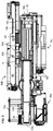
Figure 1c is a view similar tofigure 1b with a portion of housing removed in order to see internal components of the device; -
Figure 2 is a top view of the internal mechanism of the device illustrated infigure 1c wherein a needle cap removed from a syringe and the syringe is being actuated for injection; -
Figure 3 is a perspective view of an actuator of a syringe actuation mechanism or of a plunger actuation mechanism of the injection device according to an embodiment of the invention; -
Figures 4a and 4b are top and bottom views respectively of an internal mechanism of the injection device according to an embodiment of the invention in an initial position with a syringe that has just been loaded into the injection device; -
Figure 5 is a view similar tofigure 4a in a subsequent step with the syringe being clamped in the device; -
Figures 6a and 6b illustrate the mechanism in a subsequent step; -
Figures 7a to 7c illustrate perspective and plan views of a syringe cap gripper mechanism according to embodiment of the invention in an open state, andfigures 8a to 8c show the gripper mechanism in a gripping state; -
Figures 9a and 9b show the mechanism offigures 6a and 6b respectively in a subsequent step, the cap removed from the syringe body; -
Figures 10a and 10b illustrate the cap being moved laterally in a subsequent step; -
Figure 11 shows a subsequent needle insertion step, -
Figure 12 shows a subsequent drug injection step; -
Figure 13 shows a subsequent step illustrating retraction of the syringe; -
Figure 14 shows a subsequent step in which the cap is moved to align with the syringe body; -
Figure 15 shows a subsequent step it with the cap put back on to the syringe body; andFigures 16a to 16c show a subsequent step in which the cap is released by the gripper to allow removal of the syringe from the automated injection device. - Referring to the figures, an
injection device 2 according to an embodiment of the invention comprises a housing 3 having abase portion 3a andlid portion 3b. Thebase 3a comprises asyringe cradle 12 for lodging therein asyringe 1. Thesyringe 1 may be a standard type of syringe that is in widespread use for manual transcutaneous injection of a liquid drug. Such transcutaneous injection may include for example subcutaneous injections. Thesyringe 1 comprises aneedle 7, abarrel 10, possibly a glass barrel, having aflange 11, aplunger 9 for pressing the liquid out through the needle, and aneedle cap 8 for covering the needle when the syringe is not in use. - The
syringe cradle 12 is provided with a shape that allows insertion of thesyringe 1 into thebase 3a, the shape of the cradle being configured to conform to the shape of the syringe with a certain amount of play in order to allow easy insertion of the syringe in the cradle in the correct orientation. In particular, given the shape, dimensions and position of thecontainer flange 11, plunger rod and cap, there is only one orientation which thesyringe 1 may be in position within thebase 3a. The syringe may be held within thesyringe cradle 12 byflexible clip arms 40 where thelid 3b is in an opened position to keep the syringe from falling out of the cradle before the lid is closed. Asyringe ejection mechanism 47, for instance comprising one or more pivoting lever arms that engage under thesyringe container 10 configured to lift the syringe out of thecradle 12 with sufficient force to overcome theflexible clip holder 40 is provided, the ejection mechanism being activated by pressing abutton 27. Once a user has positioned aprefilled syringe 1 in thesyringe cradle 12 and closed thelid 3b over thebase 3a, aclosing switch 28 which in the illustrated embodiment is in the form of a tab connected to the base. Thisswitch 28 which may be in the form of a tab which wraps partly around the lid may provide a signal to the electronic circuit of the injection device that the lid is closed to the base. This function may be performed by many different types of sensors, for instance a proximity sensor based on magnetic, capacitive or optical sensing technology for instance or a combination thereof. An electronic circuit (not shown) within the base and / or within the lid is provided to control operation of the injection device, the injection device further comprising a power source in a form of a battery (not shown). A user interface, comprising for instance a screen, for instance provided on the inside and / or outside of thelid 3b, as well as various status indicator lights and audio output, are provided in the injection device. The user interface is configured for entering commands and providing status and information to the user, for instance to indicate the actions to be undertaken and the actions that have been completed. In addition, the device may include adocking port 46, such as for example an USB port for connecting the device either to a power supply for example to recharge or to transmit data. - The
injection device 2 comprises an internal mechanism for performing automated injection of the liquid drug, which includes: removing theneedle cap 8, advancing thesyringe 1 such that theneedle 7 extends through aneedle port 26 at askin contact face 38, advancing theplunger rod 9 by an amount corresponding to the desired injection dose, followed by withdrawing thesyringe 1 and the plunger rod, such that theneedle 7 enters back into thebase 3b, and recapping theneedle 7. The lid can then be opened and the used syringe ejected out of thecradle 12 by pressing thebutton 27 to actuate the ejection lever, allowing anew prefilled syringe 1 to be inserted in thesyringe cradle 12 for a subsequent administration. - The internal mechanism of the injection device generally includes, for performing the aforementioned operations: a
cap actuation mechanism 4 for gripping, storing and retrieving theneedle cap 8, whereby advantageously removing from and replacing theneedle cap 8 onto the syringe is with the aid of the syringe actuation mechanism, asyringe actuation mechanism 5 for advancing and withdrawing thesyringe 1 and therewith theneedle 7, and aplunger actuation mechanism 6 for advancing theplunger 9 for administration of the liquid drug. - The cap actuation mechanism comprises a
gripper 13 for holding theneedle cap 8 and anactuator 14a to actuate the gripping function and to translate theneedle cap 8 from a position aligned with theneedle 7 to a position laterally disengaged from the syringe, and its return to a position aligned with the needle after administration of the liquid drug and retraction of the syringe. Further, locking of thegripper 13 in the release/open position is also achieved by theactuator 14a. - The
syringe actuation mechanism 5 comprises anactuator 14b fixedly mounted relative to asupport frame 16b that is static with respect to thehousing base 3a. Asupport frame 16c that lodges thesyringe 1 is coupled to an output of theactuator 14b such that the actuator 14b of thesyringe actuation mechanism 5 can displace thesupport frame 16c and therewith thesyringe 1 relative to thehousing base 3a in an injection direction Id. - The
plunger actuation mechanism 6 comprises anactuator 14c that is fixedly mounted to thesyringe support frame 16c such that theactuator 14c displaces in the injection direction with the movement of thesyringe support frame 16c. The actuator 14c of the plunger actuation mechanism couples to theplunger 9 to advance the plunger in the container during administration of the liquid drug. - The
actuators syringe actuation mechanism 5 andplunger actuation mechanism 6 respectively, may have a construction as illustrated infigure 3 , the actuator being generally indicated byreference number 14. Theactuator 14 comprises anelectrical motor 17 a screw-nut mechanism comprising ascrew 20 and anut 21. Thescrew 20 is coupled to the output rotor of the motor via a gear set 18, optionally a reduction gear set 18. A slide (i.e. a guide rail) 15 is also provided to slidably guide the support frame that is coupled to thenut 21. Thescrew 20,motor 17 and slide 15 are mounted to asupport frame 16, it however being understood that the support frame may have various configurations and assembled from one or more parts for mounting not only the actuator but also housing parts in other structural elements of the device. Rotation of thescrew 20 in a first direction, respectively in a second opposite direction, translates thenut 21, in a forward, respectively reverse movement.Nut 21 is shaped such as to provide an anti-rotational mechanism preventing its rotation but enabling its translation by the rotation of thescrew 20. Theactuators plunger actuation mechanism 6 andsyringe actuation mechanism 5 can be substantially identical or may have different dimensions and configurations to accomplish the corresponding linear movements of thesyringe flange clamp 33,syringe support frame 16c, and of theplunger 9 for the needle insertion and retraction operations and for the drug administration operation. In the following description, the corresponding functional elements of theactuators syringe actuation mechanism 5 andplunger actuation mechanism 6 respectively are designated with the same reference numerals as in relation tofigure 3 but with the designation letter b or c depending on the actuator being referred to. - Referring now to
figures 2 andfigure 4 , an initial step in the operation of theinjection device 2 shall be described. In the configuration offigure 4 , asyringe 1 has been inserted into thesyringe cradle 12 and clipped elastically therein byelastic clip arms 40 so that it does not fall out of the cradle. Thesyringe flange 11 is received with some play within aslot 41 between ashoulder 42 formed on thesyringe support frame 16c and aclamp shoulder 33b formed on asyringe flange clamp 33 that is movably mounted in thesyringe support frame 16c. - The
syringe flange frame 33 extends from theclamp shoulder 33b rearwardly to a distalend release shoulder 33c (best seen infigure 2 ) that is engaged by a shoulder (not shown) formed on anactuator paddle 34a of anactuator 34 of theplunger actuation mechanism 6. Thesyringe flange clamp 33 is mounted in thesyringe support frame 16c but slidably guided and mounted on aguide 15b mounted on thesupport frame 16b fixed to thehousing base 3a. Theslide 15b also serves to slidingly guide thesyringe support frame 16c. Thesyringe flange clamp 33 comprises aguide portion 33d that slidably inserts over theslide 15b and that is biased by aspring 25 engaging aguide portion 43 fixedly coupled or integrally formed with the fixedsupport frame 16b. Theguide portion 43 thus provide the slidable guiding and holding of thesyringe support frame 16c relative to theslide 15b which is fixedly mounted to thebase 3a of the housing 3. Thesyringe support frame 16c can thus translate in the injection direction Id, guided by theslide 15b and advanced by theactuator 14b, whereby thenut 21 of the actuator (not shown infigure 4 ) is coupled to thesyringe support frame 16c and advances or reverses depending on the direction of movement of the screw (which is not seen infigure 4 because it is below theslide 15b). - As shown in
figure 4 , theclamp shoulder 33b can make a small displacement in the injection direction Id relative to thesyringe support frame 16c, whereby thespring 25 positioned therebetween biases thesyringe flange clamp 33 in the forward direction towards theskin contact face 38. In the initial position allowing insertion of thesyringe 1 in thesyringe cradle 12, theactuator paddle 34a is in its fully rearward position and engages the distalend release shoulder 33c of thesyringe flange clamp 33 to pull it backwards against the elastic force of thespring 25 such that theslot 41 allows thesyringe flange 11 to be easily inserted in theslot 41 with some play. - Initial operation of the injection device comprises actuating the actuator 14c of the plunger actuator mechanism in order to advance by a small amount the
actuator arm 34 coupled to theactuator paddle 34a such that thesyringe flange clamp 33, under the force of thespring 25 advances until it abuts theflange 11 of the syringe and clamps it against theshoulder 42 of thesyringe support flange 16c. The clamping of thesyringe flange 11 thus holds and positions thesyringe 1 in thecradle 12 in a defined position without any play. - The
plunger actuation mechanism 6 comprises the actuator 14c with the components as described in relation to the actuator offigure 3 mounted to thesyringe support frame 16c, the output of themotor 17c coupled to aplunger actuator arm 34. The actuator 14c of the plunger actuation mechanism thus moves in translation with the syringe in the injection direction Id. Theplunger actuator arm 34 is slidably mounted via aguide portion 34b on aslide 15c extending in the injection direction Id and fixedly mounted to thesyringe support frame 16c. Aposition sensor 35 may be provided on thesyringe support frame 16c to detect the most rearward position of theplunger actuation arm 34. - The
plunger actuator arm 34 comprises aplunger actuator paddle 34a that may serve two functions, a first being to retract and release thesyringe flange clamp 33 against the spring force of thespring 25 as already described above, and a second being to press theplunger 9 of thesyringe 1 during the injection operation. - Referring now to
figure 5 , in a step subsequent to clamping of thesyringe flange 11, theactuator 14b of thesyringe actuation mechanism 5 is actuated to advance thesyringe support frame 16c in the injection direction Id such that a portion of thegripper 13 of thecap actuation mechanism 4 is moved against the spring force of aspring 22 to reduce play between lockingshoulder 29 ofsecond gripper jaw 23b and the top of the needle cap in thegripper 13 within which theneedle cap 8 is positioned. Thegripper 13 of thecap actuation mechanism 4 comprises gripper jaws 23 comprising afirst jaw 23a and asecond jaw 23b that are movably mounted with respect to each other on a support frame (platform) such that they can be clamped to theneedle cap 8 as it will be described further on. - In a step subsequent to the aforementioned step, referring now to
figures 6a to 8c , a gripping operation of theneedle cap 8 will now be described. As best seen infigures 7a to 7c , in an initial ungripped position, the first andsecond gripper jaws first gripper jaw 23a is held in its defined position byseparator fingers second gripper jaw 23b is held in its defined position being biased byspring 22. Theseparator finger 24a on one of thefirst gripper jaw 23a is fixedly formed or assembled to thegripper jaw 23a. Theslideable separator finger 24b having anut portion 21a is laterally slidable with respect to thegripper jaws lateral shoulders 32 found on thegripper 13 such that theslideable separator finger 24b can move laterally to disengage theseparator finger 24a as best seen infigure 8b . Once theseparator fingers spring 36 mounted between thefirst gripper jaw 23a and the support frame, and biases first gripperjaw 23a towards thesecond gripper jaw 23b. As best seen infigures 8a and6a , thejaw 23b comprises a lockingshoulder 29 that engages an end edge of theneedle cap 8 such that the needle cap is clamped or gripped between the lockingshoulder 29 and afront wall 45 on theother jaw 23a. - The transverse displacement of the
slideable separator finger 24b is performed by ascrew 20a of a screw-nut mechanism of theactuator 14a of thecap actuation mechanism 4. Theslideable separator finger 24b thus comprises anut portion 21a that is threadably engaged by thescrew 20a of theactuator 14a. Thus, for the cap gripping operation, themotor 17a of the actuator is actuated such that theslideable separator finger 24b (seefigures 6a to 8c ) performs a transverse displacement in the transverse direction Td sufficient to disengage theseparator fingers first gripper jaw 23a to bias towards thesecond gripper jaw 23b under the force of thespring 36, the motor being stopped in this disengaged position as illustrated infigures 8b and 8c . - Referring to
figures 9a and 9b , in a subsequent step, theactuator 14b of thesyringe actuation mechanism 5 is actuated in a reverse direction to draw thesyringe support frame 16c and thesyringe 1 therewith rearwardly such that theneedle 7 is disengaged completely from theneedle cap 8. - It may be noted in this position that the
syringe support frame 16c extends rearwardly beyond the end of the housing 3 which may be provided with amoveable hat 3c to allow this rearward extension during the uncapping operation as is seen inFigure 1c . The rearwardlymoveable hat 3c allows the housing of the injection device to have a more compact form and in particular a more compact length that is only extended during the uncapping operation for greater convenience to carry and store the device between uses. - Referring to
figures 10a and 10b , in a subsequent step, thegripper 13 holding theneedle cap 8 is then fully translated by actuating themotor 17a that turns thescrew 20a engaging thenut portion 21a on theslideable separator finger 24b. Since theslideable separator finger 24b abuts against alateral shoulder 31 of thegripper 13, the gripper is translated in the transverse direction Td by sliding along theslides 15a on which thegripper 13 is slidably mounted and positioned. Theslides 15a are fixed to asupport frame 16a that holds themotor 17a and screw 20a of theactuator 14a fixedly to thebase 3a of the housing. In the illustrated embodiment, themotor 17a is connected through bevelledgears 18a that allowed the motor to be positioned longitudinally in the injection direction Id and transmit a rotation to thescrew 21a that extends in the transverse direction Td. - Referring now to
figure 11 , theactuator 14b of thesyringe actuation mechanism 5 is actuated to advance thesyringe support frame 16c and therewith thesyringe 1 to a forward most position such that theneedle 7 projects through theneedle port 26. This occurs when the skin contact face 38 of the injection device is placed against the skin of a patient. It may be noted that a proximity sensor, that may for instance advantageously be placed on thelid 3a of the housing below or as part of thecontact face 38, detects that the closed housing is positioned against the skin of the patient. Such proximity sensor may for instance detect a change in capacitance when in touch with the skin and thereby discriminate between a patient and an inanimate object. Various other physiological sensors may also be used to ensure that the injection device is activated only when it is in contact with the skin of a patient. - In a subsequent step as illustrated in
figure 12 , the drug may be injected by actuating themotor 17c of theplunger actuation mechanism 6 to advance theplunger actuation arm 34. Theactuator paddle 34a presses against the distal end of theplunger 9 to push it into thesyringe container 10. - In the following step as illustrated in
figure 13 , theplunger actuator arm 34 is moved back to its rearward most position relative to thesyringe support frame 16c and thesyringe support frame 16c is moved in a reverse direction such that the needle is retracted into the housing 3 by thesyringe actuation mechanism 5. Thegripper 13 of the cap actuation mechanism is then translated back into its initial position by actuating themotor 17a to turn thescrew 20a in a reverse direction. Since theslideable separator finger 24b is in the cap gripping position and abuts against the side of theother separator finger 24a, thegripper 13 which remains in a clamping position keeps holding thecap 8 until it translates fully back to the initial aligned position, aligned with thesyringe 1 andneedle 7. - In general, contact switches or proximity sensors may be positioned to detect the end of travel positions for each of the actuation mechanisms to stop the actuator motors once full displacement in a forward or rearward most position has occurred. The end of travel positions for each of the actuation mechanisms and to stop the respective actuator motors may also be sensed through the use of motor torque sensing through current monitoring or through sensing the number of revolutions of the actuator motor.
- In a subsequent step, as illustrated in
figure 15 , the syringe actuation mechanism may be actuated to advance thesyringe support frame 16c and therewith thesyringe 1 until theneedle 7 is capped. - In a subsequent step as illustrated in
figure 16a to 16c , thesyringe support frame 16c is further advanced such that end of the cap (8) pushesfront wall 45 onjaw 23a moving thejaw 23a against the resistance ofspring 36 such that the ends of theseparator fingers figure 16b , do not overlap and thecap actuation mechanism 4 can then be actuated to turn thescrew 20a and displace thenut portion 21a of theslideable separator finger 24b such that the ends of theseparator fingers figure 16c . Subsequently, theactuator 14b of thesyringe actuation mechanism 5 is actuated to reverse/withdraw thesyringe support frame 16c in the injection direction Id such that thesecond gripper jaw 23b is biased towards the top of thegripper support frame 16a through the biasing spring force ofspring 22 to reintroduce play between lockingshoulder 29 ofsecond gripper jaw 23b and the top of theneedle cap 8. Thegripper 13 of thecap actuation mechanism 4 is thus back to its initial position with play, and theactuator paddle 34 of theplunger actuation mechanism 6 is in its rearward most position to unclamp the syringe flange, to allow the used syringe to be removed from the injection device and a new syringe placed therein. Theactuator paddle 34 of theplunger actuation mechanism 6 in its rearward most position may be detected by thesensor 35. - Advantageously, even in the absence of
needle cap 8 in the gripper jaws, the gripper jaws can be returned from a locked/closed position into a release/open position. Thus, in the absence of asyringe 1 andneedle cap 8 the injection device can recover and open thegripper jaws second gripper jaw 23b being mounted on sliders on thegripper support frame 16a allow it to move in direction Id relative to the rest of the device. Thesecond gripper jaw 23b has anendstop 37b which is biased byspring 22 towardsendstop 37a of theplatform 38, whichplatform 38 supports thegripper jaws second gripper jaw 23b further includes a first shoulder feature (39a) whereby thesyringe support frame 16c can transmit movement in direction Id to thesecond gripper jaw 23b, against the bias ofspring 22. Further, the first and second gripper jaws each have shoulder features (39b, 39c) whereby, in the absence of a cap these shoulder features abut against each other, allowing the transmission of movement in the injection direction Id from thesecond gripper jaw 23b to thefirst gripper jaw 23a. - When the
separator fingers first gripper jaw 23a is biased towards thesecond gripper jaw 23b byspring 36 in the absence of asyringe 1 andneedle cap 8, the further advancement of thesyringe support frame 16c in the Id direction will translate thegripper 13 into the Id direction such that the ends of theseparator fingers cap actuation mechanism 4 can then be actuated to turn thescrew 20a and displace thenut portion 21a of theslideable separator finger 24b such that the ends of theseparator fingers gripper jaws syringe actuation mechanism 5 to reverse/withdraw thesyringe support frame 16c in the injection direction Id such that thesecond gripper jaw 23b is biased towards the top of thegripper support frame 16a (i.e. endstop 37b of thesecond gripper jaw 23b is biased againstendstop 37a of platform 38) through the biasing spring force ofspring 22 to open thegripper jaws gripper 13 of thecap actuation mechanism 4 is thus back to its initial position. -
-
Syringe 1-
Needle 7 -
Needle cap 8 -
Plunger 9 -
Container 10
Flange 11
-
-
Injection device 2- Housing 3
-
Base 3a-
Syringe cradle 12-
Elastic clip arms 40 -
Slot 41 for syringe flange
-
-
-
Lid 3b -
skin contact face 38 -
Needle port 26 - Syringe ejection mechanism
button 27 -
Moveable hat 3c
-
- closing
switch 28 -
syringe ejection mechanism 47 - docketing
port 46 -
support frame 16b -
Cap actuation mechanism 4-
Gripper 13-
Spring 22 - gripper jaws 23
-
lateral shoulders 32 -
first jaw 23a-
first separator finger 24a, - first
jaw shoulder feature 39c -
front wall 45
-
-
second jaw 23b- locking
shoulder 29 -
second jaw endstop 37b - second jaw shoulder features 39a, 39b
- locking
-
-
platform 38-
slideable separator finger 24b- guide 30
-
lateral shoulder 31 -
nut portion 21a
-
spring 36 -
platform endstop 37a
-
-
-
Actuator 14a-
Motor 17a
gears 18a
-
- Screw-nut mechanism
-
Screw 20a -
Nut portion 21a
-
-
Slide 15a -
Support frame 16a
-
- Housing 3
-
Syringe actuation mechanism 5-
Actuator 14b-
Motor 17b
Reduction gears 18b - Screw-nut mechanism
- Screw 20b
- Nut 21 b
-
-
Slide 15b -
Support frame 16c
shoulder 42 -
Syringe flange clamp 33-
Clamp arm 33a -
Clamp shoulder 33b - Distal
end release shoulder 33c -
Guide 33d -
Spring 25 - guide
portion 43
-
-
-
Plunger actuation mechanism 6-
Actuator 14c-
Motor 17c
Reduction gears 18c - Screw-nut mechanism
- Screw 20c
- Nut 21c
-
Actuator arm 34-
Actuator paddle 34a -
Guide 34b
-
-
-
Slide 15c -
Support frame 16c
-
- Injection direction Id
- Transverse direction Td
Claims (17)
- Injection device (2) comprising a housing (3), a syringe cradle (12) for removably receiving a syringe (1) having a needle (7), a container (10) with a flange (11), a plunger (9) and a removable needle cap (8) in the housing, and a system for performing automated injection comprising:- a cap actuation mechanism (4) for gripping, storing and retrieving the needle cap,- a syringe actuation mechanism (5) for moving the syringe in an injection direction (Id) from a position where the needle is inside the housing to an injection position where the needle projects out of a needle port of the housing on a skin contact face of the housing, and- a plunger actuation mechanism (6) for advancing the plunger for administration of the liquid drug,wherein the cap actuation mechanism comprises a movable gripper (13) for holding and releasing the needle cap and an actuator (14a) to actuate the gripping and release function and to move the gripper and therewith the needle cap from a position aligned with the needle to a position disengaged from the syringe.
- Injection device according to claim 1 wherein the actuator (14a) comprises a motor (17a) and a screw-nut linear displacement mechanism having a screw driven by the motor and engaging a nut on the gripper, the gripper being mounted on slides (15a) fixed to a support frame (16a).
- Injection device according to claim 1 or 2 wherein the gripper comprises gripper jaws comprising a first jaw (23a) and a second jaw (23b) that are movably mounted with respect to each other, the first jaw having a separator finger (24a) whereby in an ungripped position the separator finger (24a) abut against a slideable separator finger (24b) to keep the first and second jaws in a defined open position one relative to the other, and whereby the slideable separator finger (24b) is movable to disengage the separator fingers and allow the first and second jaws to move to a gripped position.
- Injection device according to the preceding claim wherein the slideable separator finger (24b) is laterally slidable in a transverse direction (Td) to the injection direction (Id) to disengage the separator fingers and allow the first and second jaws to move to a gripped position.
- Injection device according to either of the two directly preceding claims wherein the slideable separator finger (24b) is laterally slidable between lateral shoulders (32) on the gripper, such that a lateral shoulder (31) of the slideable separator finger abuts against a lateral shoulder (32) of the gripper (13) to translate the gripper in the transverse direction (Td) when the second separator is actuated.
- Injection device according to any of the three directly preceding claims wherein the slideable separator finger (24b) comprises a nut portion (21a) that is threadably engaged by the screw (20a) of said actuator (14a) of the cap actuation mechanism.
- Injection device according to any preceding claim wherein the gripper comprises a spring (36) biasing the first jaw (23a) towards the second jaw (23b).
- Injection device according to any preceding claim wherein the second jaw (23b) comprises a locking shoulder (29) that engages an end edge of the needle cap (8) such that the needle cap is clamped or gripped between the locking shoulder and a front wall (45) on the first jaw (23a).
- Injection device according to any of preceding claim wherein the syringe actuation mechanism (5) comprises an actuator (14b) fixed in the housing and a movable syringe support frame (16c) for lodging the syringe coupled to an output of the actuator (14b) to displace the syringe support frame relative to the housing in the injection direction (Id).
- Injection device according to the preceding claim wherein the actuator (14b) comprises a motor (17b) and a screw-nut linear displacement mechanism having a screw driven by the motor and engaging a nut connected to the syringe support frame (16c).
- Injection device according to any preceding claim wherein the syringe cradle comprises a slot (41) to receive the syringe flange (11) with some play between a shoulder (42) formed on the support frame (16b) and a clamp shoulder (33b) formed on a syringe flange clamp (33) that is movably mounted relative to the syringe support frame (16c) and the housing to clamp the syringe flange against the shoulder.
- Injection device according to the preceding claim wherein the syringe flange clamp (33) is biased by a spring (25) towards the clamping position.
- Injection device according to the preceding claim wherein the plunger actuation mechanism (6) comprises an actuator paddle (34a) coupled to an output of an actuator motor (17c) configured to displace the syringe plunger, whereby in its fully rearward position the actuator paddle engages the syringe flange clamp (33) to pull it backwards against the force of the spring (25) such that the slot (41) allows the syringe flange (11) to be easily inserted in the slot with some play.
- Injection device according to any preceding claim wherein the plunger actuation mechanism (6) comprises an actuator (14c) that is fixedly mounted to the syringe support frame (16c) such that the actuator displaces in the injection direction with the movement of the syringe support frame (16c) and couples to the syringe plunger (9) to advance the plunger in the container during administration of the liquid drug.
- Injection device according to any preceding claim wherein the actuator of the plunger actuation mechanism comprises a motor and a screw-nut mechanism to accomplish the corresponding linear movements of the syringe flange clamp (33) and of the plunger (9) for the drug administration operation.
- Injection device (2) comprising a housing (3), a syringe cradle (12) for removably receiving a syringe (1) having a needle (7), a container (10) with a flange (11), a plunger (9) and a removable needle cap (8) in the housing, and a system for performing automated injection comprising:- a cap actuation mechanism (4) for gripping, storing and retrieving the needle cap,- a syringe actuation mechanism (5) for moving the syringe in an injection direction (Id) from a position where the needle is inside the housing to an injection position where the needle projects out of a needle port of the housing on a skin contact face of the housing, and- a plunger actuation mechanism (6) for advancing the plunger for administration of the liquid drug,wherein the syringe cradle comprises a slot (41) to receive the syringe flange (11) with some play between a shoulder (42) formed on the support frame (16b) and a clamp shoulder (33b) formed on a syringe flange clamp (33) that is movably mounted relative to a syringe support frame (16c) and the housing to clamp the syringe flange against the shoulder.
- Injection device according to the preceding claim further comprising any one or more of the features of claims 1-10 and 12-15.
Priority Applications (9)
| Application Number | Priority Date | Filing Date | Title |
|---|---|---|---|
| EP18211425.6A EP3666314A1 (en) | 2018-12-10 | 2018-12-10 | Injection device |
| CA3122330A CA3122330A1 (en) | 2018-12-10 | 2019-12-06 | Injection device |
| PCT/EP2019/084084 WO2020120340A1 (en) | 2018-12-10 | 2019-12-06 | Injection device |
| JP2021533309A JP2022513204A (en) | 2018-12-10 | 2019-12-06 | Injection equipment |
| US17/311,823 US20220016347A1 (en) | 2018-12-10 | 2019-12-06 | Injection device |
| EP19813059.3A EP3893967A1 (en) | 2018-12-10 | 2019-12-06 | Injection device |
| AU2019396477A AU2019396477A1 (en) | 2018-12-10 | 2019-12-06 | Injection device |
| CN201980081795.4A CN113195019B (en) | 2018-12-10 | 2019-12-06 | Injection device |
| IL283820A IL283820A (en) | 2018-12-10 | 2021-06-08 | Injection device |
Applications Claiming Priority (1)
| Application Number | Priority Date | Filing Date | Title |
|---|---|---|---|
| EP18211425.6A EP3666314A1 (en) | 2018-12-10 | 2018-12-10 | Injection device |
Publications (1)
| Publication Number | Publication Date |
|---|---|
| EP3666314A1 true EP3666314A1 (en) | 2020-06-17 |
Family
ID=64664200
Family Applications (2)
| Application Number | Title | Priority Date | Filing Date |
|---|---|---|---|
| EP18211425.6A Withdrawn EP3666314A1 (en) | 2018-12-10 | 2018-12-10 | Injection device |
| EP19813059.3A Pending EP3893967A1 (en) | 2018-12-10 | 2019-12-06 | Injection device |
Family Applications After (1)
| Application Number | Title | Priority Date | Filing Date |
|---|---|---|---|
| EP19813059.3A Pending EP3893967A1 (en) | 2018-12-10 | 2019-12-06 | Injection device |
Country Status (8)
| Country | Link |
|---|---|
| US (1) | US20220016347A1 (en) |
| EP (2) | EP3666314A1 (en) |
| JP (1) | JP2022513204A (en) |
| CN (1) | CN113195019B (en) |
| AU (1) | AU2019396477A1 (en) |
| CA (1) | CA3122330A1 (en) |
| IL (1) | IL283820A (en) |
| WO (1) | WO2020120340A1 (en) |
Cited By (1)
| Publication number | Priority date | Publication date | Assignee | Title |
|---|---|---|---|---|
| WO2022135966A1 (en) * | 2020-12-24 | 2022-06-30 | Shl Medical Ag | Mechanisms for receiving injector |
Families Citing this family (3)
| Publication number | Priority date | Publication date | Assignee | Title |
|---|---|---|---|---|
| CN110823562B (en) | 2019-10-12 | 2020-07-28 | 重庆大学 | Experiment system and method capable of simulating gear transmission non-inertial system environment |
| US20230293101A1 (en) * | 2021-07-16 | 2023-09-21 | Eli Lilly And Company | Methods and systems for selecting an injection site |
| CN117298381B (en) * | 2023-11-02 | 2024-04-19 | 厦门眼科中心有限公司 | Anesthetic quantitative injection device for anesthesia department |
Citations (3)
| Publication number | Priority date | Publication date | Assignee | Title |
|---|---|---|---|---|
| EP2301611A1 (en) * | 2009-09-25 | 2011-03-30 | Letcat Aktiebolag | Medical delivery device |
| WO2014026937A1 (en) * | 2012-08-15 | 2014-02-20 | Sanofi-Aventis Deutschland Gmbh | Autoinjector |
| JP5890371B2 (en) * | 2013-10-18 | 2016-03-22 | アッヴィ合同会社 | Self-injection aid and self-injection system |
Family Cites Families (9)
| Publication number | Priority date | Publication date | Assignee | Title |
|---|---|---|---|---|
| US5085641A (en) * | 1989-07-17 | 1992-02-04 | Survival Technology, Inc. | Conveniently carried frequent use auto-injector with improved cap structure |
| GB2438593B (en) * | 2006-06-01 | 2011-03-30 | Cilag Gmbh Int | Injection device (cap removal feature) |
| GB2451663B (en) * | 2007-08-08 | 2012-09-26 | Cilag Gmbh Int | Injection device |
| BRPI1009100A2 (en) * | 2009-03-13 | 2016-03-08 | Lilly Co Eli | apparatus for injecting a pharmaceutical with automatic retraction of syringe followed by injection |
| EP2468338A1 (en) * | 2010-12-21 | 2012-06-27 | Sanofi-Aventis Deutschland GmbH | Auto-injector |
| CN203252997U (en) * | 2013-04-18 | 2013-10-30 | 冯琼 | Anti-pricking device for injection syringe |
| FR3011186B1 (en) * | 2013-09-30 | 2017-12-08 | Rexam Healthcare La Verpillier | RECEPTION DEVICE FOR AN INJECTION SYRINGE COMPRISING A NEEDLE PROTECTIVE CAP |
| TW201707741A (en) * | 2015-06-03 | 2017-03-01 | 賽諾菲阿凡提斯德意志有限公司 | Grasper for a needle sheath, cap, autoinjector and method of producing a grasper |
| EP3380161A1 (en) * | 2015-11-27 | 2018-10-03 | Sanofi-Aventis Deutschland GmbH | A cap for an injection device |
-
2018
- 2018-12-10 EP EP18211425.6A patent/EP3666314A1/en not_active Withdrawn
-
2019
- 2019-12-06 WO PCT/EP2019/084084 patent/WO2020120340A1/en unknown
- 2019-12-06 CA CA3122330A patent/CA3122330A1/en active Pending
- 2019-12-06 JP JP2021533309A patent/JP2022513204A/en active Pending
- 2019-12-06 US US17/311,823 patent/US20220016347A1/en active Pending
- 2019-12-06 EP EP19813059.3A patent/EP3893967A1/en active Pending
- 2019-12-06 AU AU2019396477A patent/AU2019396477A1/en active Pending
- 2019-12-06 CN CN201980081795.4A patent/CN113195019B/en active Active
-
2021
- 2021-06-08 IL IL283820A patent/IL283820A/en unknown
Patent Citations (3)
| Publication number | Priority date | Publication date | Assignee | Title |
|---|---|---|---|---|
| EP2301611A1 (en) * | 2009-09-25 | 2011-03-30 | Letcat Aktiebolag | Medical delivery device |
| WO2014026937A1 (en) * | 2012-08-15 | 2014-02-20 | Sanofi-Aventis Deutschland Gmbh | Autoinjector |
| JP5890371B2 (en) * | 2013-10-18 | 2016-03-22 | アッヴィ合同会社 | Self-injection aid and self-injection system |
Cited By (1)
| Publication number | Priority date | Publication date | Assignee | Title |
|---|---|---|---|---|
| WO2022135966A1 (en) * | 2020-12-24 | 2022-06-30 | Shl Medical Ag | Mechanisms for receiving injector |
Also Published As
| Publication number | Publication date |
|---|---|
| EP3893967A1 (en) | 2021-10-20 |
| CA3122330A1 (en) | 2020-06-18 |
| JP2022513204A (en) | 2022-02-07 |
| CN113195019B (en) | 2023-05-30 |
| CN113195019A (en) | 2021-07-30 |
| AU2019396477A1 (en) | 2021-06-24 |
| WO2020120340A1 (en) | 2020-06-18 |
| US20220016347A1 (en) | 2022-01-20 |
| IL283820A (en) | 2021-07-29 |
Similar Documents
| Publication | Publication Date | Title |
|---|---|---|
| US20220016347A1 (en) | Injection device | |
| CN113164686B (en) | Automatic injection device and cartridge | |
| CN102307605B (en) | Medicament delivery devices | |
| JP5437343B2 (en) | Hand-held electronically controlled injection machine for liquid drug injection | |
| EP2682145B1 (en) | Syringe and syringe assembly | |
| EP3202445B1 (en) | Pharmaceutical syringe unit, pharmaceutical injection device equipped with said unit, injection needle attachment and removal fixture, and storage case | |
| EP1660158B1 (en) | Syringe with automatically triggered safety sleeve | |
| US5779679A (en) | Winged IV set with retractable needle | |
| US20140371683A1 (en) | Medication administering device | |
| TW201404419A (en) | Drive control mechanisms and automatic injectors for injectable cartridges | |
| AU2018233465A1 (en) | Injector device | |
| EP3781236B1 (en) | Status sensing system for injection device | |
| JP2005287676A (en) | Medical injection appliance | |
| EP3895748A2 (en) | Safe injector needle | |
| CN212854248U (en) | Electronic injection pen | |
| CN111407975A (en) | Electronic injection pen | |
| US10052439B2 (en) | Resetting mechanism for drug delivery device and resettable drug delivery device | |
| JP2020509872A (en) | Puncture mechanism and cartridge puncture system | |
| EP3656303A1 (en) | Blood withdrawal system with lancet ejection mechanism | |
| WO2018167136A1 (en) | Piercing mechanism and cartridge piercing system | |
| WO2012072083A1 (en) | Safety needle device |
Legal Events
| Date | Code | Title | Description |
|---|---|---|---|
| PUAI | Public reference made under article 153(3) epc to a published international application that has entered the european phase |
Free format text: ORIGINAL CODE: 0009012 |
|
| STAA | Information on the status of an ep patent application or granted ep patent |
Free format text: STATUS: THE APPLICATION HAS BEEN PUBLISHED |
|
| AK | Designated contracting states |
Kind code of ref document: A1 Designated state(s): AL AT BE BG CH CY CZ DE DK EE ES FI FR GB GR HR HU IE IS IT LI LT LU LV MC MK MT NL NO PL PT RO RS SE SI SK SM TR |
|
| AX | Request for extension of the european patent |
Extension state: BA ME |
|
| STAA | Information on the status of an ep patent application or granted ep patent |
Free format text: STATUS: THE APPLICATION IS DEEMED TO BE WITHDRAWN |
|
| 18D | Application deemed to be withdrawn |
Effective date: 20201218 |