JP5634026B2 - Differential fluid pressure measuring device - Google Patents
Differential fluid pressure measuring device Download PDFInfo
- Publication number
- JP5634026B2 JP5634026B2 JP2009012874A JP2009012874A JP5634026B2 JP 5634026 B2 JP5634026 B2 JP 5634026B2 JP 2009012874 A JP2009012874 A JP 2009012874A JP 2009012874 A JP2009012874 A JP 2009012874A JP 5634026 B2 JP5634026 B2 JP 5634026B2
- Authority
- JP
- Japan
- Prior art keywords
- fluid pressure
- sensing element
- sensor device
- pressure sensor
- passage
- Prior art date
- Legal status (The legal status is an assumption and is not a legal conclusion. Google has not performed a legal analysis and makes no representation as to the accuracy of the status listed.)
- Expired - Fee Related
Links
- 239000012530 fluid Substances 0.000 title claims description 43
- 229910052751 metal Inorganic materials 0.000 claims description 22
- 239000002184 metal Substances 0.000 claims description 22
- 239000000463 material Substances 0.000 claims description 14
- 239000004033 plastic Substances 0.000 claims description 4
- 229920003023 plastic Polymers 0.000 claims description 4
- 239000000919 ceramic Substances 0.000 claims description 3
- 230000003750 conditioning effect Effects 0.000 claims description 3
- 238000012544 monitoring process Methods 0.000 claims 1
- 239000011347 resin Substances 0.000 claims 1
- 229920005989 resin Polymers 0.000 claims 1
- 239000000853 adhesive Substances 0.000 description 7
- 230000001070 adhesive effect Effects 0.000 description 7
- 238000002347 injection Methods 0.000 description 7
- 239000007924 injection Substances 0.000 description 7
- 230000005484 gravity Effects 0.000 description 4
- 229910001220 stainless steel Inorganic materials 0.000 description 4
- 239000010935 stainless steel Substances 0.000 description 4
- 239000004697 Polyetherimide Substances 0.000 description 3
- 239000011521 glass Substances 0.000 description 3
- 238000000034 method Methods 0.000 description 3
- 229920001601 polyetherimide Polymers 0.000 description 3
- PNEYBMLMFCGWSK-UHFFFAOYSA-N aluminium oxide Inorganic materials [O-2].[O-2].[O-2].[Al+3].[Al+3] PNEYBMLMFCGWSK-UHFFFAOYSA-N 0.000 description 2
- 229920002545 silicone oil Polymers 0.000 description 2
- 229910001369 Brass Inorganic materials 0.000 description 1
- 239000004593 Epoxy Substances 0.000 description 1
- 229910001200 Ferrotitanium Inorganic materials 0.000 description 1
- UCKMPCXJQFINFW-UHFFFAOYSA-N Sulphide Chemical compound [S-2] UCKMPCXJQFINFW-UHFFFAOYSA-N 0.000 description 1
- RTAQQCXQSZGOHL-UHFFFAOYSA-N Titanium Chemical compound [Ti] RTAQQCXQSZGOHL-UHFFFAOYSA-N 0.000 description 1
- 238000009825 accumulation Methods 0.000 description 1
- 230000002378 acidificating effect Effects 0.000 description 1
- 239000010951 brass Substances 0.000 description 1
- 229920001971 elastomer Polymers 0.000 description 1
- 239000000806 elastomer Substances 0.000 description 1
- 230000007774 longterm Effects 0.000 description 1
- 238000012986 modification Methods 0.000 description 1
- 230000004048 modification Effects 0.000 description 1
- 229910052758 niobium Inorganic materials 0.000 description 1
- 239000010955 niobium Substances 0.000 description 1
- GUCVJGMIXFAOAE-UHFFFAOYSA-N niobium atom Chemical compound [Nb] GUCVJGMIXFAOAE-UHFFFAOYSA-N 0.000 description 1
- 229920006389 polyphenyl polymer Polymers 0.000 description 1
- 229920001296 polysiloxane Polymers 0.000 description 1
- 239000000565 sealant Substances 0.000 description 1
- 239000003566 sealing material Substances 0.000 description 1
- 239000004065 semiconductor Substances 0.000 description 1
- 239000002210 silicon-based material Substances 0.000 description 1
- 239000004071 soot Substances 0.000 description 1
- 239000000126 substance Substances 0.000 description 1
- 229910052715 tantalum Inorganic materials 0.000 description 1
- GUVRBAGPIYLISA-UHFFFAOYSA-N tantalum atom Chemical compound [Ta] GUVRBAGPIYLISA-UHFFFAOYSA-N 0.000 description 1
- 239000010936 titanium Substances 0.000 description 1
- XLYOFNOQVPJJNP-UHFFFAOYSA-N water Substances O XLYOFNOQVPJJNP-UHFFFAOYSA-N 0.000 description 1
Images


Classifications
-
- G—PHYSICS
- G01—MEASURING; TESTING
- G01L—MEASURING FORCE, STRESS, TORQUE, WORK, MECHANICAL POWER, MECHANICAL EFFICIENCY, OR FLUID PRESSURE
- G01L13/00—Devices or apparatus for measuring differences of two or more fluid pressure values
-
- G—PHYSICS
- G01—MEASURING; TESTING
- G01L—MEASURING FORCE, STRESS, TORQUE, WORK, MECHANICAL POWER, MECHANICAL EFFICIENCY, OR FLUID PRESSURE
- G01L13/00—Devices or apparatus for measuring differences of two or more fluid pressure values
- G01L13/02—Devices or apparatus for measuring differences of two or more fluid pressure values using elastically-deformable members or pistons as sensing elements
- G01L13/025—Devices or apparatus for measuring differences of two or more fluid pressure values using elastically-deformable members or pistons as sensing elements using diaphragms
-
- G—PHYSICS
- G01—MEASURING; TESTING
- G01L—MEASURING FORCE, STRESS, TORQUE, WORK, MECHANICAL POWER, MECHANICAL EFFICIENCY, OR FLUID PRESSURE
- G01L7/00—Measuring the steady or quasi-steady pressure of a fluid or a fluent solid material by mechanical or fluid pressure-sensitive elements
- G01L7/02—Measuring the steady or quasi-steady pressure of a fluid or a fluent solid material by mechanical or fluid pressure-sensitive elements in the form of elastically-deformable gauges
- G01L7/08—Measuring the steady or quasi-steady pressure of a fluid or a fluent solid material by mechanical or fluid pressure-sensitive elements in the form of elastically-deformable gauges of the flexible-diaphragm type
-
- G—PHYSICS
- G01—MEASURING; TESTING
- G01L—MEASURING FORCE, STRESS, TORQUE, WORK, MECHANICAL POWER, MECHANICAL EFFICIENCY, OR FLUID PRESSURE
- G01L9/00—Measuring steady of quasi-steady pressure of fluid or fluent solid material by electric or magnetic pressure-sensitive elements; Transmitting or indicating the displacement of mechanical pressure-sensitive elements, used to measure the steady or quasi-steady pressure of a fluid or fluent solid material, by electric or magnetic means
- G01L9/02—Measuring steady of quasi-steady pressure of fluid or fluent solid material by electric or magnetic pressure-sensitive elements; Transmitting or indicating the displacement of mechanical pressure-sensitive elements, used to measure the steady or quasi-steady pressure of a fluid or fluent solid material, by electric or magnetic means by making use of variations in ohmic resistance, e.g. of potentiometers, electric circuits therefor, e.g. bridges, amplifiers or signal conditioning
- G01L9/06—Measuring steady of quasi-steady pressure of fluid or fluent solid material by electric or magnetic pressure-sensitive elements; Transmitting or indicating the displacement of mechanical pressure-sensitive elements, used to measure the steady or quasi-steady pressure of a fluid or fluent solid material, by electric or magnetic means by making use of variations in ohmic resistance, e.g. of potentiometers, electric circuits therefor, e.g. bridges, amplifiers or signal conditioning of piezo-resistive devices
Landscapes
- Physics & Mathematics (AREA)
- General Physics & Mathematics (AREA)
- Measuring Fluid Pressure (AREA)
Description
本出願は、概して流体圧力を測定する装置に関し、特に、高い圧力源および低い圧力源の各々と通じる流体内に配置するための2つのダイヤフラムを用いた、媒体と隔離された差動圧力センサを提供するような装置に関する。 This application relates generally to an apparatus for measuring fluid pressure, and in particular to a differential pressure sensor isolated from a medium, using two diaphragms for placement in fluid that communicates with each of a high pressure source and a low pressure source. It relates to a device as provided.
ピエゾ抵抗圧力感知素子のような半導体圧力感知素子は、媒体に対して頑丈なフレキシブルな金属ダイヤフラムによって感知される媒体から隔離され、保護される。典型的にシリコーンオイルのような非圧縮性流体は、ダイヤフラムから感知素子へ圧力を伝達するのに使用される。一般に、対向する方向に面する第1および第2のダイヤフラムが提供され、それらの間に感知素子が配置される。センサに損傷を及ぼしかねないダイヤフラム上の媒体からのすす(soot)、水、凝縮液のような物質の蓄積を減少させるため、重力や圧力ポートに対して排水可能な方向にダイヤフラムを置くことがしばしば要求される。例えば、2007年4月3日に発行された米国特許第7,197、936号では、ダイヤフラムの表面は、重力の方向に平行に配向されている。これは、所望の剛性を提供するために、特許に示されているように分厚い搭載ブラケットの使用をも必要とする高いアスペクト比になる。さらに、ダイヤフラムが対向する方向で直面するダイヤフラムの搭載は、各々が感知される媒体に頑丈であることを必要とする分離されたハウジング部材の使用を要求され得る。 Semiconductor pressure sensing elements, such as piezoresistive pressure sensing elements, are isolated and protected from the sensed medium by a flexible metal diaphragm that is rugged to the medium. Typically, an incompressible fluid such as silicone oil is used to transfer pressure from the diaphragm to the sensing element. In general, first and second diaphragms facing in opposite directions are provided, and a sensing element is disposed therebetween. To reduce the accumulation of substances such as soot, water, and condensate from the media on the diaphragm that could damage the sensor, place the diaphragm in a direction that allows drainage with respect to gravity and pressure ports. Often required. For example, in US Pat. No. 7,197,936 issued April 3, 2007, the surface of the diaphragm is oriented parallel to the direction of gravity. This results in a high aspect ratio that also requires the use of a thick mounting bracket as shown in the patent to provide the desired stiffness. Further, the mounting of diaphragms facing in the opposite direction of the diaphragms may require the use of separate housing members that each need to be robust to the sensed medium.
本発明の目的は、ダイヤフラムの表面が重力の方向と垂直であるように容易に配向することができる差動流体圧力センサを提供することである。本発明の他の目的は、コンパクトであり、かつ典型的に要求されるものよりも高価な材料でないものから作ることができる差動流体圧力センサを提供することである
。さらなる本発明の目的は、その表面が時間節約の組立動作の使用を可能にする差動流体圧力センサを提供することである。
It is an object of the present invention to provide a differential fluid pressure sensor that can be easily oriented so that the surface of the diaphragm is perpendicular to the direction of gravity. Another object of the present invention is to provide a differential fluid pressure sensor that is compact and can be made from materials that are typically less expensive than those required. It is a further object of the present invention to provide a differential fluid pressure sensor whose surface allows use of time saving assembly operations.
簡潔に、本発明の好ましい実施例では、ベースには、共通の方向に面するダイヤフラム搭載面から離れて2つの離間された開口間を延びる通路が形成される。1つの開口は、拡大され、ピエゾ抵抗感知素子アッセンブリのような流体圧力応答感知素子を受け取る。ダイヤフラムおよび通路は、感知素子へ圧力を伝達するための非圧縮性のオイルが充填される2つのチャンバーを形成する。 Briefly, in the preferred embodiment of the present invention, the base is formed with a passage extending between two spaced openings away from the diaphragm mounting surface facing in a common direction. One opening is enlarged to receive a fluid pressure responsive sensing element, such as a piezoresistive sensing element assembly. The diaphragm and passage form two chambers filled with incompressible oil for transmitting pressure to the sensing element.
ベースの一方の面に双方のダイヤフラムを持つことは、組立工程を簡単にする。例えば、ダイヤフラムの取り付けのための接着性のリングを形成し、ダイヤフラムをリング上に配置し、かつキュア(curing)することは、双方のダイヤフラムについて同時に行うことができる。 Having both diaphragms on one side of the base simplifies the assembly process. For example, forming an adhesive ring for attachment of the diaphragm, placing the diaphragm on the ring, and curing can be done on both diaphragms simultaneously.
以下に述べる本発明の好ましい実施例では、感知素子は、端子ピンの一方の端部へのワイヤボンドに接続され、端子ピンの他方の端部は、条件付け回路を有するプリント回路基板に結合され、これは、次に、金属スプリングによってコネクタ端子に接続される。シーラント(封止剤)がピンの周りに配置され、ピン/ベースのインターフェースを介してオイル漏れが防止される。 In the preferred embodiment of the invention described below, the sensing element is connected to a wire bond to one end of the terminal pin, the other end of the terminal pin being coupled to a printed circuit board having conditioning circuitry; This is then connected to the connector terminal by a metal spring. A sealant is placed around the pin to prevent oil leakage through the pin / base interface.
本発明の例示的な実施例が図面に提示され、かつ明細書に説明される。
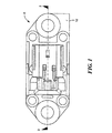
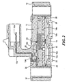
特に図1および図2を参照すると、本発明の第1の好ましい実施例に従い作成された差動流体圧力センサアッセンブリ10は、例えばPEI(ポリエーテルイミド)のような適切なモールド可能な材料からなる上部ハウジング12を含み、上部ハウジング12には、3つのインサートモールドされた端子12b(図2に1つが示されている)を有するコネクタ部分12aが形成される。監視されるべき高低の流体圧力源のポートを有するサポートにアッセンブリを搭載するため、上部ハウジングは12には、金属ブッシング(軸受筒)16間に感知素子モジュール14を受け取るための窪みが形成されている。PEIのような適切なモールド可能な材料からなる下部ハウジング18は、図2に示されるように、圧力感知モジュール14の下方に上部ハウジング12の窪みに受容される。
With particular reference to FIGS. 1 and 2, a differential fluid
取り囲むOリング20は、上部ハウジング12と感知素子モジュール14の表面との間に形成された回路チャンバー12cに形成されたシートに配置される。回路ボード22は、チャンバー12c内の感知素子モジュール14の表面に配置される。コンタクトスプリング24は、各々の端子12bの端部12dと回路ボード22間の上部ハウジング12の壁の適切なボア(口径)内を延在し、図2にはそのような1つのスプリングが示されている。アッセンブリおよびキャリブレーションの直後に、でボアは、RTVのような適切な材料で封止される。
The surrounding O-
感知素子モジュール14は、並んで、第1および第2のほぼ円形状の金属ディスク14a、14bを搭載するボディ(本体)を含む。第1および第2のディスクは、後述される。下部ハウジング18には、各ディスク14a、14bと整合されOリング26を受け取るためのOリングシートが形成される。各ポート18a、18bには、好ましくは、開口を規定するクロスバーのようなグリル状の配列が形成され、そこを介して流体が流され、図2の断面図は、バーの1つで切り取られている。外部Oリング28は、下部ハウジング18の底面の各ポート18a、18bの周りの適切なOリングシート内に配置され、センサアッセンブリ10と高低の流体圧力源を含むハウジング(図示されない)との間に流体シールを提供する。
The
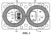
図3および4を参照すると、フレキシブルな金属ダイヤフラムの搭載前の感知素子モジュール14が示されている。感知素子モジュール14は、PPS(ポリフェニールサルファイド)のような適切な材料からなるベースのような概ね硬いプレートのように形成され、平坦な底面14cを有する。窪み14dは、底面14cに形成され、金属ディスク14a、14bを伴うように構成され、ディスク14a、14bの底面が同じ方向に面し、かつ好ましくは同一面に横たわる。ディスク14a、14bには、それぞれのディスクを介して窓14fが形成され、窪み14dは、各々の窓に延在しかつ各窓の全体的な外周に選択された深さのチャンネル14eを形成するように構成される。チャンネル14eは、エラストマー(弾性的な)シール材が充填され、オイル漏れを防止する。
Referring to FIGS. 3 and 4, the
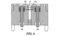
ほぼU字形状の通路14gは、モジュールのベースを介して形成され、ディスク14aの窓14fの面14cの開口からディスク14bの窓14fの面14cの開口まで通じる。第1の実施例の特徴によれば、U字形状の通路の湾部(bight portion)は、真鍮または他の適切な材料からなるチューブ14hによって形成されている。ディスク14bの窓14fの通路の一端の拡大された開口14kには、図5および図6により明瞭に示されるように、ピエゾ抵抗素子15のような圧力感知素子の配置が提供され、圧力感知素子は、シリコーンベースの接着剤または他の適切な接着材料15aによって拡大された開口14kのフランジに取り付けられる。ワイヤ15cは、圧力感知素子15と各電気端子ピン15d間に結合される。接着性のジェル(gel)は、端子ピンと周囲のプラスチック間の強固な圧力封止を提供するために使用される。
A substantially
エポキシやシリコーンベースの材料からなる適切な接着材料14Iは、図3に示されるように、円形状のリングまたは窓14fを越える他の所望の幾何学をステンシル塗りまたはディスペンス(分配)することによりディスク14a、14bの外側の表面に塗布され、それからフレキシブル金属ダイヤフラム14mがディスク14a、14bの各搭載面上に取り付けられる。
A suitable adhesive material 14I comprised of an epoxy or silicone based material can be obtained by stenciling or dispensing a circular ring or other desired geometry beyond the
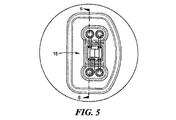
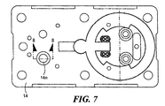
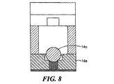
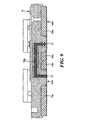
感知素子の上面を示す図7を参照すると、図4と同様に、オイル注入穴14nがベースと各ディスク14a、14bとを通して形成される。通路は空にされ、そして、オイル注入穴14nを介してシリコーンオイルのような非圧縮性の流体が充填され、それから、ディスク14a、14bに溶接された図8に示すボール14oによってシールされ、図9に示すアッセンブリが提供される。
Referring to FIG. 7 showing the top surface of the sensing element, as in FIG. 4, an
ベースの一方の面上に双方のダイヤフラムを持つことは、上記したように組立工程を簡易にすることが理解されよう。例えば、接着性のリングを形成し、ダイヤフラムを位置決めし、かつ接着剤をキュアすることは、双方のダイヤフラムについて同時になし得ることができる。もし、所望ならば、さらなる工程の簡略化のため、2つの分離されたダイヤフラムの部材ではなく、単一部材の金属を使用することができる。長期間の信頼性のため、使用されるダイヤフラムは、感知される媒体(流体)に対して不浸透性でありかつ頑強であることが必要とされる。例えば、酸性の排出ガス媒体の使用のために適切な材料は、タンタル、ニオブ、チタンおよびステンレススチールを含むことができる。 It will be appreciated that having both diaphragms on one side of the base simplifies the assembly process as described above. For example, forming an adhesive ring, positioning the diaphragm, and curing the adhesive can be done simultaneously for both diaphragms. If desired, a single piece of metal can be used rather than two separate diaphragm pieces for further process simplification. For long-term reliability, the diaphragm used is required to be impervious and robust to the sensed medium (fluid). For example, suitable materials for use with acidic exhaust gas media can include tantalum, niobium, titanium, and stainless steel.
本発明に従い、センサアッセンブリ10は、重力に対して垂直な面に横たわるダイヤフラムの表面に搭載することができ、すなわち、図2に示すようにである。これは、従来技術で使用された金属ブラケットの必要をなくしたよりコンパクトなセンサアッセンブリとなる。本発明のセンサ装置は、感知される媒体に対して頑強である唯一のハウジング部材、すなわち下部ハウジング18を必要とし、その結果、他の部材は、高価でない材料を使用することが可能である。
In accordance with the present invention, the
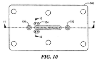
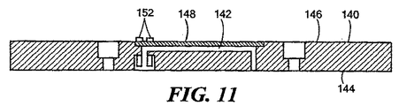
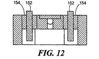
もし、所望ならば、感知素子モジュールは、図4のモールド可能なプラスチック以外の材料から形成することができる。第2の好ましい実施例に従い、感知素子モジュールは、図10−12に示されるように、ステンレス鋼のような適切な材料から形成することができる。図10において、モジュール140は、ステンレス鋼から形成されたベース部材を含み、さらに平坦な面144に開口するほぼU字形状の通路142を有し、その結果、ダイヤフラムを平坦な面144上に直接取り付けることができる。通路142は、ステンレス鋼のプレート部材148またはモジュール140に溶接可能な部材によって、上面146で閉じられたトレンチ(溝)によって形成される。通路142の1つの開口は、図1、2の素子15に対応するピエゾ抵抗感知素子を受容するために拡大される。端子ピン152は、ガラスシール154によって搭載されかつ絶縁される。オイル注入穴156は、図7のオイル注入穴14nに対応する。
If desired, the sensing element module can be formed from materials other than the moldable plastic of FIG. In accordance with the second preferred embodiment, the sensing element module can be formed from a suitable material, such as stainless steel, as shown in FIGS. 10-12. In FIG. 10, the
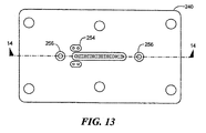
セラミックに関して、センサ感知モジュール240は、図13および14に示され、例えばアルミナから形成することができ、モジュール140の実施例と同様の方法で、底面244を通して開口する対応するU字形状の通路242が形成される。通路は、アルミナのカバー246またはモジュール240にガラスで取り付けられる部材によって閉じられる。オイル注入穴256は、第2の実施例のオイル注入穴156に対応する。この場合、オイル注入穴は、プラスチックプラグで密封することができる。ガラス254で搭載された端子ピン252は、本実施例でも同様に使用され得る。
With respect to ceramic, the
種々の変更は、本発明を逸脱することなく上記の構成に成しえることができ、上記の記載に含まれまたは添付図面に示されたすべての事項は、例示として解釈されかつ限定されるものでないことを意図している。 Various modifications can be made to the above configuration without departing from the present invention, and all matters included in the above description are interpreted and limited as examples. Is not intended.
Claims (13)
共通の方向に面する第1および第2のダイヤフラム搭載面を有する感知素子モジュールを搭載するハウジングと、
前記感知素子モジュールは、窪みによってそれぞれ離間された第1および第2の窓を有し、第1および第2の窓は、前記第1および第2のダイヤフラム搭載面の一部を提供し、
前記感知素子モジュール内に形成され、かつ第1および第2のダイヤフラム搭載面間を延在しかつ搭載面の内側に開口を形成する通路と、
第1および第2のダイヤフラム搭載面上であって各々の開口上に搭載されるフレキシブルな金属ダイヤフラムと、
前記通路の開口の1つに配置された圧力応答感知素子と、
通路を充填しかつ前記金属ダイヤフラムと係合し通路内に封止される非圧縮性流体と、
前記圧力応答感知素子に動作可能に接続された電気信号条件付け回路と、
監視のために、前記金属ダイヤフラムに高い流体圧力と低い流体圧力をそれぞれ提示する第1および第2の流体圧力接続手段とを有し、
前記通路は、間に湾部を有する2つの脚部を有するほぼU字形状であり、一方の脚部が第1の窓に接続され、他方の脚部が第2の窓に接続され、前記湾部は金属製のチューブを有する、差動流体圧力センサ装置。 A differential fluid pressure sensor device comprising:
A housing for mounting a sensing element module having first and second diaphragm mounting surfaces facing in a common direction;
The sensing element module has first and second windows spaced apart by a recess, respectively, the first and second windows providing part of the first and second diaphragm mounting surfaces;
A passage formed in the sensing element module and extending between the first and second diaphragm mounting surfaces and forming an opening inside the mounting surface;
A flexible metal diaphragm mounted on each opening on the first and second diaphragm mounting surfaces;
A pressure sensitive sensing element disposed in one of the openings in the passage;
An incompressible fluid filling the passage and engaging the metal diaphragm and sealed within the passage;
An electrical signal conditioning circuit operatively connected to the pressure responsive sensing element;
First and second fluid pressure connection means for presenting a high fluid pressure and a low fluid pressure, respectively, to the metal diaphragm for monitoring;
The passage is generally U-shaped with two legs with a bay in between, one leg connected to the first window, the other leg connected to the second window, A differential fluid pressure sensor device in which the bay has a metal tube.
ハウジングと、
ハウジング内に搭載された感知素子モジュールであって、感知素子モジュールは、第1および第2の金属ダイヤフラム搭載ディスクを搭載し、第1および第2のディスクは、それぞれ平坦なダイヤフラム搭載面を有し、第1および第2の搭載面は共通の方向に面しており、窪みによってそれぞれ離間された第1および第2の窓がそれぞれ第1および第2のディスクを介して形成されかつ第1および第2の窓は第1および第2の金属ダイヤフラム搭載面の一部を提供し、通路が感知素子モジュール内に形成されかつ第1および第2の窓の間を延在する、前記感知素子モジュールと、
流体シールされた関係でかつ第1および第2の金属ダイヤフラム搭載面上に搭載されかつ第1および第2の窓上に延在するフレキシブルな金属ダイヤフラムと、
前記通路を充填しかつ前記金属ダイヤフラムと係合しかつ通路内に封止される非圧縮性流体と、
第1のディスクの窓の前記通路内の圧力を受け取る通路内に配置され、各ダイヤフラムによって伝達された流体圧力の差に応答する圧力応答感知素子と、
前記圧力応答感知素子に動作可能に接続された電気信号条件付け回路と、
第1および第2のダイヤフラムとの流体伝達において前記ハウジング上に搭載された第1および第2の流体圧力接続手段とを有し、
前記通路は、間に湾部を有する2つの脚部を有するほぼU字形状であり、一方の脚部が第1の窓に接続され、他方の脚部が第2の窓に接続され、前記湾部は金属製のチューブを有する、差動流体圧力センサ装置。 A differential fluid pressure sensor device comprising:
A housing;
A sensing element module mounted in a housing, wherein the sensing element module includes first and second metal diaphragm mounting disks, and each of the first and second disks has a flat diaphragm mounting surface. The first and second mounting surfaces face in a common direction, and first and second windows , respectively, separated by depressions are formed through the first and second discs, respectively, and The sensing element module, wherein the second window provides a portion of the first and second metal diaphragm mounting surfaces , and a passage is formed in the sensing element module and extends between the first and second windows. When,
A flexible metal diaphragm mounted in fluid sealed relation on the first and second metal diaphragm mounting surfaces and extending on the first and second windows;
An incompressible fluid filling the passage and engaging the metal diaphragm and sealed within the passage;
A pressure responsive sensing element disposed in a passage for receiving pressure in the passage of the first disk window and responsive to a difference in fluid pressure transmitted by each diaphragm;
An electrical signal conditioning circuit operatively connected to the pressure responsive sensing element;
First and second fluid pressure connection means mounted on the housing in fluid communication with the first and second diaphragms;
The passage is generally U-shaped with two legs with a bay in between, one leg connected to the first window, the other leg connected to the second window, A differential fluid pressure sensor device in which the bay has a metal tube.
Applications Claiming Priority (2)
| Application Number | Priority Date | Filing Date | Title |
|---|---|---|---|
| US12/069,522 | 2008-02-11 | ||
| US12/069,522 US7578194B1 (en) | 2008-02-11 | 2008-02-11 | Differential fluid pressure measurement apparatus |
Publications (2)
| Publication Number | Publication Date |
|---|---|
| JP2009186467A JP2009186467A (en) | 2009-08-20 |
| JP5634026B2 true JP5634026B2 (en) | 2014-12-03 |
Family
ID=40612974
Family Applications (1)
| Application Number | Title | Priority Date | Filing Date |
|---|---|---|---|
| JP2009012874A Expired - Fee Related JP5634026B2 (en) | 2008-02-11 | 2009-01-23 | Differential fluid pressure measuring device |
Country Status (5)
| Country | Link |
|---|---|
| US (1) | US7578194B1 (en) |
| EP (1) | EP2088414A3 (en) |
| JP (1) | JP5634026B2 (en) |
| KR (1) | KR101530092B1 (en) |
| CN (1) | CN101509817B (en) |
Cited By (1)
| Publication number | Priority date | Publication date | Assignee | Title |
|---|---|---|---|---|
| JP2015232538A (en) * | 2013-11-18 | 2015-12-24 | センサータ テクノロジーズ インコーポレーテッド | Mems pressure sensor field shield layout for surface charge immunity in oil filled packaging |
Families Citing this family (33)
| Publication number | Priority date | Publication date | Assignee | Title |
|---|---|---|---|---|
| CN101743462B (en) * | 2007-07-12 | 2014-08-20 | Abb研究有限公司 | Pressure sensor |
| US8082797B2 (en) * | 2009-11-11 | 2011-12-27 | Honeywell International Inc. | Pressure sensor assembly |
| US8375799B2 (en) | 2010-12-10 | 2013-02-19 | Honeywell International Inc. | Increased sensor die adhesion |
| US8915140B2 (en) | 2011-04-08 | 2014-12-23 | Rosemount Inc. | Corrosion resistant isolator assembly for process devices |
| DE102011102837A1 (en) * | 2011-05-30 | 2012-12-06 | Epcos Ag | Pressure sensor and method for producing a pressure sensor |
| KR101303419B1 (en) * | 2011-10-28 | 2013-09-05 | 주식회사 현대케피코 | Differential Pressure Sensor |
| CN103278285A (en) * | 2013-06-08 | 2013-09-04 | 无锡隆盛科技股份有限公司 | Differential pressure sensor |
| US9103739B2 (en) | 2013-09-27 | 2015-08-11 | Rosemount Inc. | Seal for pressure transmitter for use in industrial process |
| US20150135853A1 (en) * | 2013-11-18 | 2015-05-21 | Mark P. McNeal | Mems pressure sensor field shield layout for surface charge immunity in oil filled packaging |
| US9316552B2 (en) * | 2014-02-28 | 2016-04-19 | Measurement Specialties, Inc. | Differential pressure sensing die |
| US9593995B2 (en) * | 2014-02-28 | 2017-03-14 | Measurement Specialties, Inc. | Package for a differential pressure sensing die |
| EP3112830B1 (en) | 2015-07-01 | 2018-08-22 | Sensata Technologies, Inc. | Temperature sensor and method for the production of a temperature sensor |
| CN105067181B (en) * | 2015-08-12 | 2017-11-28 | 凯龙高科技股份有限公司 | A kind of gas differential pressure sensor |
| US9638559B1 (en) | 2016-02-10 | 2017-05-02 | Sensata Technologies Inc. | System, devices and methods for measuring differential and absolute pressure utilizing two MEMS sense elements |
| CN107290099B (en) | 2016-04-11 | 2021-06-08 | 森萨塔科技公司 | Pressure sensor, plug for a pressure sensor and method for producing a plug |
| EP3236226B1 (en) | 2016-04-20 | 2019-07-24 | Sensata Technologies, Inc. | Method of manufacturing a pressure sensor |
| KR101734851B1 (en) | 2016-09-30 | 2017-05-16 | 대한민국 | Tension meter with pressure compensatory function |
| US10428716B2 (en) | 2016-12-20 | 2019-10-01 | Sensata Technologies, Inc. | High-temperature exhaust sensor |
| US10545064B2 (en) | 2017-05-04 | 2020-01-28 | Sensata Technologies, Inc. | Integrated pressure and temperature sensor |
| US10502641B2 (en) | 2017-05-18 | 2019-12-10 | Sensata Technologies, Inc. | Floating conductor housing |
| US10323998B2 (en) | 2017-06-30 | 2019-06-18 | Sensata Technologies, Inc. | Fluid pressure sensor |
| US10724907B2 (en) | 2017-07-12 | 2020-07-28 | Sensata Technologies, Inc. | Pressure sensor element with glass barrier material configured for increased capacitive response |
| US10557770B2 (en) | 2017-09-14 | 2020-02-11 | Sensata Technologies, Inc. | Pressure sensor with improved strain gauge |
| US10605686B2 (en) * | 2017-10-19 | 2020-03-31 | Veoneer Us, Inc. | Dual wet and dry combination mounting |
| CN107884243B (en) * | 2017-11-13 | 2020-07-03 | 刘俊香 | Quick smear device of clinical examination |
| EP3534131B1 (en) * | 2018-03-02 | 2021-06-02 | Grundfos Holding A/S | Pressure sensor |
| CN108713800A (en) * | 2018-07-27 | 2018-10-30 | 广元元亨科技有限公司 | It is a kind of can dynamic control heating wire temperature smoke controllable type electronic cigarette |
| CN108713799A (en) * | 2018-07-27 | 2018-10-30 | 广元元亨科技有限公司 | A kind of high-reliability pinpoint accuracy smoke controllable type electronic cigarette |
| CN209326840U (en) | 2018-12-27 | 2019-08-30 | 热敏碟公司 | Pressure sensor and pressure transmitter |
| CN214471485U (en) * | 2020-10-18 | 2021-10-22 | 武汉飞恩微电子有限公司 | Sintered seat, core structure and pressure sensor |
| CN112129453A (en) * | 2020-10-18 | 2020-12-25 | 武汉飞恩微电子有限公司 | Sintering seat, core body structure, base assembly and differential pressure sensor |
| US12313483B2 (en) * | 2023-03-31 | 2025-05-27 | Te Connectivity Solutions Gmbh | Sensor having a plurality of diaphragms |
| CN119492477B (en) * | 2023-08-14 | 2025-10-28 | 精量电子(深圳)有限公司 | Differential pressure sensor and differential pressure detection device |
Family Cites Families (20)
| Publication number | Priority date | Publication date | Assignee | Title |
|---|---|---|---|---|
| FR1553013A (en) * | 1966-11-26 | 1969-01-10 | ||
| US3901082A (en) * | 1973-10-01 | 1975-08-26 | Itt | Fluid pressure sensing system and differential pressure unit therefor |
| US4370890A (en) * | 1980-10-06 | 1983-02-01 | Rosemount Inc. | Capacitive pressure transducer with isolated sensing diaphragm |
| JPS6048136U (en) * | 1983-09-12 | 1985-04-04 | 株式会社日立製作所 | Fully differential pressure transducer |
| JPS60181642U (en) * | 1984-05-12 | 1985-12-02 | 株式会社山武 | differential pressure transmitter |
| US4625560A (en) * | 1985-05-13 | 1986-12-02 | The Scott & Fetzer Company | Capacitive digital integrated circuit pressure transducer |
| US4754365A (en) * | 1987-06-15 | 1988-06-28 | Fischer & Porter Company | Differential pressure transducer |
| US4841777A (en) * | 1988-03-22 | 1989-06-27 | Honeywell Inc. | Pressure transmitter assembly |
| JPH02280027A (en) * | 1989-04-21 | 1990-11-16 | Yokogawa Electric Corp | Differential pressure measuring instrument |
| US4909083A (en) * | 1989-06-26 | 1990-03-20 | Itt Corporation | Pressure/differential pressure measuring device |
| US5184514A (en) * | 1991-07-12 | 1993-02-09 | Rosemount Inc. | Corrosion resistant isolator |
| JPH05346363A (en) * | 1992-06-16 | 1993-12-27 | Hitachi Ltd | Difference pressure transmitter |
| SG41962A1 (en) * | 1993-09-24 | 1997-08-15 | Rosemount Inc | Pressure transmitter isolation diaphragm |
| US5672808A (en) * | 1996-06-11 | 1997-09-30 | Moore Products Co. | Transducer having redundant pressure sensors |
| JPH10300613A (en) * | 1997-04-23 | 1998-11-13 | Hitachi Ltd | Differential pressure transmitter |
| JP2003315193A (en) * | 2002-04-24 | 2003-11-06 | Denso Corp | Pressure sensor |
| JP2005156307A (en) * | 2003-11-25 | 2005-06-16 | Denso Corp | Pressure sensor |
| US7117745B2 (en) * | 2004-02-09 | 2006-10-10 | Rosemount Inc. | Process seal for process control transmitter |
| JP2005249515A (en) * | 2004-03-03 | 2005-09-15 | Denso Corp | Pressure sensor |
| US7234357B2 (en) * | 2004-10-18 | 2007-06-26 | Silverbrook Research Pty Ltd | Wafer bonded pressure sensor |
-
2008
- 2008-02-11 US US12/069,522 patent/US7578194B1/en active Active
-
2009
- 2009-01-23 JP JP2009012874A patent/JP5634026B2/en not_active Expired - Fee Related
- 2009-02-06 KR KR1020090009831A patent/KR101530092B1/en not_active Expired - Fee Related
- 2009-02-10 CN CN200910005868XA patent/CN101509817B/en not_active Expired - Fee Related
- 2009-02-11 EP EP09250331.7A patent/EP2088414A3/en not_active Withdrawn
Cited By (1)
| Publication number | Priority date | Publication date | Assignee | Title |
|---|---|---|---|---|
| JP2015232538A (en) * | 2013-11-18 | 2015-12-24 | センサータ テクノロジーズ インコーポレーテッド | Mems pressure sensor field shield layout for surface charge immunity in oil filled packaging |
Also Published As
| Publication number | Publication date |
|---|---|
| KR101530092B1 (en) | 2015-06-18 |
| EP2088414A3 (en) | 2016-04-27 |
| JP2009186467A (en) | 2009-08-20 |
| US7578194B1 (en) | 2009-08-25 |
| CN101509817A (en) | 2009-08-19 |
| KR20090086909A (en) | 2009-08-14 |
| EP2088414A2 (en) | 2009-08-12 |
| US20090199647A1 (en) | 2009-08-13 |
| CN101509817B (en) | 2012-02-15 |
Similar Documents
| Publication | Publication Date | Title |
|---|---|---|
| JP5634026B2 (en) | Differential fluid pressure measuring device | |
| CN102589791B (en) | Pressure sensor with low cost package | |
| JP5127140B2 (en) | Pressure / temperature common transducer | |
| CN101900625B (en) | Design of wet/wet differential pressure sensor based on microelectronic packaging process | |
| US10466125B2 (en) | Pressure sensor sub assembly and fabrication | |
| US5522267A (en) | Modular diaphragm pressure sensor with peripherally mounted electrical terminals | |
| US9310267B2 (en) | Differential pressure sensor | |
| KR102276887B1 (en) | Package for a differential pressure sensing die | |
| CN107782485B (en) | Differential pressure sensor integrated with common mode error compensation | |
| US20050120798A1 (en) | Isolated pressure transducer | |
| JP2001527210A (en) | Universal media package for pressure sensing devices | |
| NO301252B1 (en) | Low cost wet-to-wet pressure sensor package | |
| CN101371118A (en) | Design of Wet/Wet Amplified Differential Pressure Sensor Based on Silicon Piezoresistive Technology | |
| CA2940374A1 (en) | Differential pressure sensing die | |
| CN111837021A (en) | Differential pressure sensor for determining the magnitude of the differential pressure | |
| US11953391B2 (en) | Differential pressure sensor and method of using the same | |
| JP2020528150A (en) | Pressure sensor assemblies, measuring instruments, and how they are manufactured | |
| EP0497534B1 (en) | Piezoresistive pressure transducer with a conductive elastomeric seal | |
| JPH02280026A (en) | Semiconductor type pressure detecting device | |
| CN106461485A (en) | Pressure sensor for sensing the pressure of the fluid medium in the measuring chamber | |
| KR20150131439A (en) | Device for measuring pressure | |
| KR20130138943A (en) | Closed-type pressure transducer | |
| JP2001272296A (en) | Pressure sensor | |
| JP2002296136A (en) | Case structure of transducer | |
| JPH0436424Y2 (en) |
Legal Events
| Date | Code | Title | Description |
|---|---|---|---|
| A621 | Written request for application examination |
Free format text: JAPANESE INTERMEDIATE CODE: A621 Effective date: 20110926 |
|
| A977 | Report on retrieval |
Free format text: JAPANESE INTERMEDIATE CODE: A971007 Effective date: 20130308 |
|
| A131 | Notification of reasons for refusal |
Free format text: JAPANESE INTERMEDIATE CODE: A131 Effective date: 20130312 |
|
| A521 | Request for written amendment filed |
Free format text: JAPANESE INTERMEDIATE CODE: A523 Effective date: 20130514 |
|
| A131 | Notification of reasons for refusal |
Free format text: JAPANESE INTERMEDIATE CODE: A131 Effective date: 20140128 |
|
| A521 | Request for written amendment filed |
Free format text: JAPANESE INTERMEDIATE CODE: A523 Effective date: 20140411 |
|
| TRDD | Decision of grant or rejection written | ||
| A01 | Written decision to grant a patent or to grant a registration (utility model) |
Free format text: JAPANESE INTERMEDIATE CODE: A01 Effective date: 20141014 |
|
| A61 | First payment of annual fees (during grant procedure) |
Free format text: JAPANESE INTERMEDIATE CODE: A61 Effective date: 20141014 |
|
| R150 | Certificate of patent or registration of utility model |
Ref document number: 5634026 Country of ref document: JP Free format text: JAPANESE INTERMEDIATE CODE: R150 |
|
| R250 | Receipt of annual fees |
Free format text: JAPANESE INTERMEDIATE CODE: R250 |
|
| R250 | Receipt of annual fees |
Free format text: JAPANESE INTERMEDIATE CODE: R250 |
|
| R250 | Receipt of annual fees |
Free format text: JAPANESE INTERMEDIATE CODE: R250 |
|
| R250 | Receipt of annual fees |
Free format text: JAPANESE INTERMEDIATE CODE: R250 |
|
| LAPS | Cancellation because of no payment of annual fees |