JP5599328B2 - Connection mechanism between power semiconductor device and printed wiring board - Google Patents
Connection mechanism between power semiconductor device and printed wiring board Download PDFInfo
- Publication number
- JP5599328B2 JP5599328B2 JP2011009539A JP2011009539A JP5599328B2 JP 5599328 B2 JP5599328 B2 JP 5599328B2 JP 2011009539 A JP2011009539 A JP 2011009539A JP 2011009539 A JP2011009539 A JP 2011009539A JP 5599328 B2 JP5599328 B2 JP 5599328B2
- Authority
- JP
- Japan
- Prior art keywords
- semiconductor device
- power semiconductor
- fitting member
- wiring board
- printed wiring
- Prior art date
- Legal status (The legal status is an assumption and is not a legal conclusion. Google has not performed a legal analysis and makes no representation as to the accuracy of the status listed.)
- Expired - Fee Related
Links
Images


Classifications
-
- H—ELECTRICITY
- H05—ELECTRIC TECHNIQUES NOT OTHERWISE PROVIDED FOR
- H05K—PRINTED CIRCUITS; CASINGS OR CONSTRUCTIONAL DETAILS OF ELECTRIC APPARATUS; MANUFACTURE OF ASSEMBLAGES OF ELECTRICAL COMPONENTS
- H05K3/00—Apparatus or processes for manufacturing printed circuits
- H05K3/30—Assembling printed circuits with electric components, e.g. with resistor
- H05K3/32—Assembling printed circuits with electric components, e.g. with resistor electrically connecting electric components or wires to printed circuits
- H05K3/325—Assembling printed circuits with electric components, e.g. with resistor electrically connecting electric components or wires to printed circuits by abutting or pinching, i.e. without alloying process; mechanical auxiliary parts therefor
-
- H—ELECTRICITY
- H01—ELECTRIC ELEMENTS
- H01L—SEMICONDUCTOR DEVICES NOT COVERED BY CLASS H10
- H01L2924/00—Indexing scheme for arrangements or methods for connecting or disconnecting semiconductor or solid-state bodies as covered by H01L24/00
- H01L2924/0001—Technical content checked by a classifier
- H01L2924/0002—Not covered by any one of groups H01L24/00, H01L24/00 and H01L2224/00
-
- H—ELECTRICITY
- H05—ELECTRIC TECHNIQUES NOT OTHERWISE PROVIDED FOR
- H05K—PRINTED CIRCUITS; CASINGS OR CONSTRUCTIONAL DETAILS OF ELECTRIC APPARATUS; MANUFACTURE OF ASSEMBLAGES OF ELECTRICAL COMPONENTS
- H05K2201/00—Indexing scheme relating to printed circuits covered by H05K1/00
- H05K2201/03—Conductive materials
- H05K2201/0302—Properties and characteristics in general
- H05K2201/0311—Metallic part with specific elastic properties, e.g. bent piece of metal as electrical contact
-
- H—ELECTRICITY
- H05—ELECTRIC TECHNIQUES NOT OTHERWISE PROVIDED FOR
- H05K—PRINTED CIRCUITS; CASINGS OR CONSTRUCTIONAL DETAILS OF ELECTRIC APPARATUS; MANUFACTURE OF ASSEMBLAGES OF ELECTRICAL COMPONENTS
- H05K2201/00—Indexing scheme relating to printed circuits covered by H05K1/00
- H05K2201/10—Details of components or other objects attached to or integrated in a printed circuit board
- H05K2201/10007—Types of components
- H05K2201/10166—Transistor
-
- H—ELECTRICITY
- H05—ELECTRIC TECHNIQUES NOT OTHERWISE PROVIDED FOR
- H05K—PRINTED CIRCUITS; CASINGS OR CONSTRUCTIONAL DETAILS OF ELECTRIC APPARATUS; MANUFACTURE OF ASSEMBLAGES OF ELECTRICAL COMPONENTS
- H05K2201/00—Indexing scheme relating to printed circuits covered by H05K1/00
- H05K2201/10—Details of components or other objects attached to or integrated in a printed circuit board
- H05K2201/10227—Other objects, e.g. metallic pieces
- H05K2201/1031—Surface mounted metallic connector elements
-
- H—ELECTRICITY
- H05—ELECTRIC TECHNIQUES NOT OTHERWISE PROVIDED FOR
- H05K—PRINTED CIRCUITS; CASINGS OR CONSTRUCTIONAL DETAILS OF ELECTRIC APPARATUS; MANUFACTURE OF ASSEMBLAGES OF ELECTRICAL COMPONENTS
- H05K2201/00—Indexing scheme relating to printed circuits covered by H05K1/00
- H05K2201/10—Details of components or other objects attached to or integrated in a printed circuit board
- H05K2201/10431—Details of mounted components
- H05K2201/1059—Connections made by press-fit insertion
-
- Y—GENERAL TAGGING OF NEW TECHNOLOGICAL DEVELOPMENTS; GENERAL TAGGING OF CROSS-SECTIONAL TECHNOLOGIES SPANNING OVER SEVERAL SECTIONS OF THE IPC; TECHNICAL SUBJECTS COVERED BY FORMER USPC CROSS-REFERENCE ART COLLECTIONS [XRACs] AND DIGESTS
- Y02—TECHNOLOGIES OR APPLICATIONS FOR MITIGATION OR ADAPTATION AGAINST CLIMATE CHANGE
- Y02P—CLIMATE CHANGE MITIGATION TECHNOLOGIES IN THE PRODUCTION OR PROCESSING OF GOODS
- Y02P70/00—Climate change mitigation technologies in the production process for final industrial or consumer products
- Y02P70/50—Manufacturing or production processes characterised by the final manufactured product
Landscapes
- Engineering & Computer Science (AREA)
- Metallurgy (AREA)
- Manufacturing & Machinery (AREA)
- Microelectronics & Electronic Packaging (AREA)
- Structures For Mounting Electric Components On Printed Circuit Boards (AREA)
- Coupling Device And Connection With Printed Circuit (AREA)
Description
本発明は、電力用半導体装置とそれを搭載するプリント配線板との接続構造に関するものである。 The present invention relates to a connection structure between a power semiconductor device and a printed wiring board on which the power semiconductor device is mounted.
パワーモジュール等の電力用半導体装置(パワー半導体装置)は、大電流および高電圧を制御するため、パワー半導体装置と外部のプリント配線板との間で電力損失の少ない接続を実現すること、および、パワー半導体装置内の電力用半導体素子(パワー半導体素子)から発せられる熱を効率よく外部に逃がすことが、不可欠とされている。そのためパワー半導体装置内およびプリント基板上の各配線パターンの低抵抗化や、各接続部における接続抵抗の低減ならびに接続信頼性の向上は重要な課題である。 A power semiconductor device such as a power module (power semiconductor device) controls a large current and a high voltage, thereby realizing a connection with low power loss between the power semiconductor device and an external printed wiring board, and It is indispensable to efficiently release the heat generated from the power semiconductor element (power semiconductor element) in the power semiconductor device to the outside. Therefore, it is important to reduce the resistance of each wiring pattern in the power semiconductor device and on the printed circuit board, to reduce the connection resistance at each connection portion, and to improve the connection reliability.
一方、組み立て作業の簡略化の観点から、パワー半導体装置とプリント配線板との接続を容易且つ高い信頼性で実現できる技術も種々提案されている。例えば下記の特許文献1では、パワー半導体装置の外部端子として、当該パワー半導体装置の表面から突出する線材ピンを使用した構成が提案されている。この構成において、パワー半導体装置内の基板(内部基板)と線材ピンとの接続は、内部基板上に設けられた金属製の筒状部材(ブッシュ)に線材ピンを挿入することで成される。また線材ピンと外部のプリント配線板との接続は、プリント配線板のスルーホールに線材ピンを挿入して半田付けすること(スルーホール接続方式)で成される。
On the other hand, from the viewpoint of simplifying the assembling work, various techniques have been proposed that can realize the connection between the power semiconductor device and the printed wiring board easily and with high reliability. For example,
また特許文献2では、パワー半導体装置とプリント配線板との接続を、押し付け接触方式によって実現し、接続作業の簡易化を図った例が示されている。特許文献2では、信頼性の高い接続を得るために、パワー半導体装置の外部端子として、金属を屈曲させたバネ状部材(接触バネ)が用いられている。
Further,
特許文献1では、パワー半導体装置の外部端子として線材ピンは内部基板上のブッシュに挿入され、当該線材ピンとブッシュの内面との摩擦力により保持される。そのためパワー半導体装置の内部基板と外部端子との間で充分に高い接続信頼性が得られないことが考えられる。さらに、外部端子とプリント配線板との接続が、スルーホール接続方式であるため、プリント配線板の製造過程でスルーホールの形成工程が必要になる他、パワー半導体装置のプリント配線板への実装過程で半田付け工程が必要になる。
In
特に、大電流を制御するパワー半導体装置では、線材ピンの本数を増やす必要があるため、スルーホールの数と半田付け個所の数が増大し、コストアップの要因となる。また大電流を制御するパワー半導体装置ではその発熱も大きくなるため、プリント配線板と線材ピンとの熱膨張係数の違いに起因する応力によって半田にクラックが生じる恐れもある。クラックが生じると、線材ピンとプリント配線板との接続抵抗が増大すると共に、接合強度が低下して信頼性が低下する懸念がある。 In particular, in a power semiconductor device that controls a large current, it is necessary to increase the number of wire pins, which increases the number of through-holes and the number of soldering points, leading to an increase in cost. In addition, the power semiconductor device that controls a large current also generates a large amount of heat, which may cause cracks in the solder due to the stress caused by the difference in thermal expansion coefficient between the printed wiring board and the wire pins. When the crack occurs, there is a concern that the connection resistance between the wire pin and the printed wiring board increases, and the bonding strength decreases and the reliability decreases.
また特許文献2では、パワー半導体装置の外部端子として接触バネを用いているが、接触バネはその構造が故に、内部基板の配線パターンとの接触面積やプリント配線板のパッド部との接触面積が小さいため、外部端子一つあたりの電流容量が低い。そのため大電流を制御するパワー半導体装置では必要となる接触バネの数が多くなり、装置の小型化の妨げとなる。また接触バネは、金属を屈曲させたものであるため、電流が流れる経路が長くなり電力損失が大きくなるという欠点もある。
Further, in
本発明は以上のような課題を解決するためになされたものであり、パワー半導体装置と外部のプリント配線板との接続において、接続信頼性の向上、電力損失の低減、製造コストの削減、接続工程の簡略化および接続構造の小型化を実現可能な接続構造を提供することを目的とする。 The present invention has been made to solve the above problems, and in the connection between the power semiconductor device and the external printed wiring board, the connection reliability is improved, the power loss is reduced, the manufacturing cost is reduced, and the connection is made. It is an object of the present invention to provide a connection structure capable of simplifying the process and reducing the size of the connection structure.
本発明に係る電力用半導体装置とプリント配線板との接続機構は、前記電力用半導体装置が、前記プリント配線板との対向面に突出した外部端子である導電性の嵌入部材を備え、前記プリント配線板が、当該プリント配線板のパッド部上に実装され、前記電力用半導体装置が当該プリント配線板に接続されるときに前記嵌入部材が挿入される導電性の嵌合部材を備え、前記嵌入部材は、側面に凹部を有し、前記嵌合部材は、内側面に弾性を有する凸部を有し、前記嵌入部材が前記嵌合部材に挿入されたとき、前記嵌合部材の前記凸部が前記弾性により前記嵌入部材の前記凹部に圧接し、前記電力用半導体装置は、当該電力用半導体装置の表面を覆うモールド樹脂と、前記モールド樹脂を貫通して前記電力用半導体装置の内部基板上の配線に達する開口部と、前記開口部内に配設され、前記配線と接続した金属製のブッシュとを備え、前記嵌入部材は、前記ブッシュに挿入されたプレスフィット部を備えるものである。
The connection mechanism between the power semiconductor device and the printed wiring board according to the present invention is characterized in that the power semiconductor device includes a conductive fitting member that is an external terminal protruding on a surface facing the printed wiring board, A wiring board is mounted on a pad portion of the printed wiring board, and includes a conductive fitting member into which the insertion member is inserted when the power semiconductor device is connected to the printed wiring board. The member has a concave portion on a side surface, the fitting member has a convex portion having elasticity on an inner side surface, and the convex portion of the fitting member when the fitting member is inserted into the fitting member. Is pressed against the recess of the fitting member by the elasticity , and the power semiconductor device includes a mold resin that covers a surface of the power semiconductor device and an inner substrate of the power semiconductor device that penetrates the mold resin. Reaching the wiring That an opening is disposed in the opening, and a metal bushing that is connected to the wiring, the insert member is a shall comprise a press-fit portion that is inserted into the bush.
本発明によれば、嵌合部材の凸部が、その弾性力により嵌入部材の凹部に押圧されることによって、機械的に強い接続が得られる。また振動にも強く、長期信頼性にも優れている。また凸部が凹部に当接することで、嵌合部材と嵌入部材との接触面積を大きくでき、両者間で電気的に損失が少ない接続が得られると共に、高い熱伝導性が得られる。 According to the present invention, a mechanically strong connection is obtained by pressing the convex portion of the fitting member against the concave portion of the fitting member by its elastic force. It is also resistant to vibration and has excellent long-term reliability. Moreover, when the convex part abuts on the concave part, the contact area between the fitting member and the fitting member can be increased, and a connection with little electrical loss can be obtained between the two, and high thermal conductivity can be obtained.
<実施の形態1>
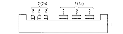
図1は、本発明の実施の形態1に係るパワー半導体装置1の構成を示す図である。当該パワー半導体装置1の上面(後述のプリント配線板3と対向する面)に、外部端子としての金属で形成された導電性の嵌入部材2が配設されている。各嵌入部材2は、パワー半導体装置1の上面から突出しており、それぞれの高さは全て同一となっている。
<
FIG. 1 is a diagram showing a configuration of a
図1のパワー半導体装置1には、比較的幅の広い電流端子用の嵌入部材2aと、比較的幅の狭い信号端子用の嵌入部材2bとが設けられている。以下、特に断りのない限り、「嵌入部材2」とは、電流端子用の嵌入部材2aおよび信号端子用の嵌入部材2bの両方を指すものとする。嵌入部材2の構造の詳細については後述する。
The
また図2は、本発明の実施の形態1に係るプリント配線板3の構成を示す図である。図1のパワー半導体装置1はこのプリント配線板3に実装される。プリント配線板3の下面(パワー半導体装置1と対向する面)には、パワー半導体装置1の各嵌入部材2に対応する位置に、嵌入部材2を受け入れる金属で形成された導電性の嵌合部材4が配設されている。各嵌合部材4は、プリント配線板3の下面から突出しており、それぞれの高さは全て同一となっている。
Moreover, FIG. 2 is a figure which shows the structure of the printed wiring board 3 which concerns on
図2のプリント配線板3には、パワー半導体装置1の電流端子用の嵌入部材2aに対応する位置に、比較的幅の広い電流端子用の嵌合部材4aが配設され、パワー半導体装置1の信号端子用の嵌入部材2bに対応する位置に、比較的幅の狭い信号端子用の嵌合部材4bが設けられる。以下、特に断りのない限り、「嵌合部材4」とは、電流端子用の嵌合部材4aおよび信号端子用の嵌合部材4bの両方を指すものとする。嵌合部材4の構造の詳細については後述する。
The printed wiring board 3 in FIG. 2 is provided with a relatively wide current
図3は、パワー半導体装置1がプリント配線板3に装着された状態を示す図である。パワー半導体装置1をプリント配線板3に実装する際には、互いに対応する嵌入部材2と嵌合部材4とが対向するように、パワー半導体装置1とプリント配線板3とを位置合わせし、パワー半導体装置1をプリント配線板3に押し付ける。これにより嵌入部材2が嵌合部材4に押し込まれて保持される。その結果、嵌入部材2と嵌合部材4とが電気的に接続されると共にパワー半導体装置1がプリント配線板3に固定される。
FIG. 3 is a diagram illustrating a state where the
パワー半導体装置1とプリント配線板3との位置合わせは、例えばパワー半導体装置1およびプリント配線板3を貫通するように設けられた、放熱フィンへの取り付け用のネジ穴(不図示)を用いて行うことができる。またパワー半導体装置1をプリント配線板3に押し付ける際には、例えば平坦な金属板などの押し付け用冶具を用いるとよい。平坦な押し付け用治具を、パワー半導体装置1の下面(嵌入部材2が配設された反対側の面)に押し当てると、パワー半導体装置1の下面全体に均一な力を加えることができ、パワー半導体装置1に歪みが生じることが防止できる。
The alignment between the
また上記したように、パワー半導体装置1から突出する複数の嵌入部材2は高さが揃っており、プリント配線板3上に実装された複数の嵌合部材4の高さも揃っている。よって嵌入部材2が嵌合部材4に押し込まれるとき、複数の嵌入部材2および嵌合部材4のそれぞれに均一に力が加わり、全ての嵌入部材2を嵌合部材4へ確実に押し込むことができる。
As described above, the plurality of
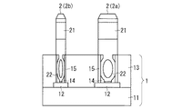
図4は、パワー半導体装置1における嵌入部材2の近傍の拡大断面図である。同図では電流端子用の嵌入部材2aと、信号端子用の嵌入部材2bを示している。電流端子用の嵌入部材2aは、大電流を流すことが可能なように、信号端子用の嵌入部材2bよりも幅を広くして、断面積を大きくしている。図4では電流端子用の嵌入部材2aの断面積を大きくするためにその幅を広くしたが、厚さを大きくしてもよい。用途に応じて幅または厚さの異なる嵌入部材2を使い分けることにより、必要な嵌入部材2の本数および形成面積を少なくでき、パワー半導体装置1の小型化が可能になる。
FIG. 4 is an enlarged cross-sectional view in the vicinity of the
また図5は嵌入部材2の正面図および側面図である。電流端子用の嵌入部材2aと信号端子用の嵌入部材2bとの違いは幅または厚さのみなので(上記したように両者の高さは同じである)、以下では両者を区別せずに説明する。
FIG. 5 is a front view and a side view of the
パワー半導体装置1は、いわゆるトランスファーモールド型のモジュールであり、図4のように、半導体素子が作り込まれた内部基板11と、その表面を覆うモールド樹脂13とを備える。パワー半導体装置1をモールド樹脂13で覆った構造とすることにより、嵌入部材2間の高い絶縁信頼性が得られる。モールド樹脂13としては、例えば、フィラーとしてシリカ粉末が充填されたエポキシ樹脂が用いられる。そのシリカ粉末の含有率は、パワー半導体装置1に用いられる部材の熱膨張係数などを考慮して最適な量が選定される。
The
モールド樹脂13の所定個所には、内部基板11上の配線パターン12に達する開口部14が形成されており、開口部14内には、配線パターン12と電気的に接続した金属製のブッシュ15が配設されている。ブッシュ15の長さは、開口部14の深さと同じである。すなわちブッシュ15は、底部が配線パターン12に接続し、上部がモールド樹脂13の上面に達している。
An
図5のように、嵌入部材2は、上部の側面に凹部21を有し、下部にはプレスフィット部22を有している。プレスフィット部22は、ブッシュ15の内径よりも若干幅広に形成されている。嵌入部材2のパワー半導体装置1への実装は、図4のように、嵌入部材2のプレスフィット部22をブッシュ15内へ挿入することによって行われる。それによりプレスフィット部22とブッシュ15との間に、機械的および電気的な接続が得られる。またこの構成によれば、嵌入部材2のプレスフィット部22をブッシュ15に挿入したときの位置精度がよく、嵌入部材2と嵌合部材4と位置合わせ精度を高くできる。
As shown in FIG. 5, the
嵌入部材2とブッシュ15との間で機械的および電気的な接続を得る手法としては、プレスフィット方式以外にも、半田付けやばね締め等の手法も考えられる。また嵌入部材2の下部(ブッシュ15への挿入部分)をスプリング形状にする方法も考えられる。しかしパワー半導体装置の外部端子には、接合の長期信頼性や高い位置精度が要求され、また加工コスト、装着作業の簡便性、電流容量などの面からも、プレスフィット接合が最適と考えられるため、本実施の形態ではプレスフィット方式を採用した。
As a method for obtaining mechanical and electrical connection between the
嵌入部材2の凹部21は、その表面がR(round)形状の曲面であり、嵌入部材2の両側面に対称に設けられている。凹部21は、図6のように1対のみ設けてもよいし、図7のように2対、あるいはそれ以上の個数設けてもよい。後述する嵌合部材4の形状は、嵌入部材2の凹部21の位置、大きさ、個数に応じたものとなる。
The
また図5に示す嵌入部材2の側面図から分かるように、嵌入部材2は1枚の平らな(折れ曲がりのない)金属板で形成されている。嵌入部材2が平らな形状であるため、嵌入部材2を流れる電流の経路が最短になり、パワー半導体装置1の外部端子の低損失化、低インダクタンス化および大電流化を実現できる。また1枚の金属板を加工して得られる嵌入部材2は、その内部に接続部が無いため電流損失が少ない。
Further, as can be seen from the side view of the
図8は、プリント配線板3における嵌合部材4の近傍の拡大断面図である。同図では、電流端子用の嵌合部材4aと、信号端子用の嵌合部材4bを示している。電流端子用の嵌合部材4aは、パワー半導体装置1の電流端子用の嵌入部材2aに対応した位置に配設され、また電流端子用の嵌入部材2aに合わせて幅が広くなっている。信号端子用の嵌合部材4bは、パワー半導体装置1の信号端子用の嵌入部材2bに対応した位置に配設され、信号端子用の嵌入部材2bに合わせて幅が狭くなっている。
FIG. 8 is an enlarged cross-sectional view of the vicinity of the
図8においては、図4のように電流端子用の嵌入部材2aを信号端子用の嵌入部材2bよりも幅広にした場合に対応させて、電流端子用の嵌合部材4aを信号端子用の嵌合部材4bよりも幅広にした例を示している。しかし、例えば電流端子用の嵌入部材2aを信号端子用の嵌入部材2bよりも厚く構成する場合には、電流端子用の嵌合部材4aの奥行き(アーム部の間隔)を広くすればよい。電流端子用の嵌合部材4aと信号端子用の嵌合部材4bとの違いは幅または奥行きのみなので(上記したように両者の高さは同じである)、以下では両者を区別せずに説明する。
In FIG. 8, the current
図8のように嵌合部材4は、プリント配線板3の表面に形成されたプリント配線の一部であるパッド部31上に、半田32を介して接合される。半田32の厚みは、熱抵抗および電気抵抗を小さくするために、接合信頼性が低下しない範囲で、薄いことが望ましい。半田32に代えて、銀ナノペーストを用いてパッド部31と嵌合部材4との接合を行えば、さらなる低抵抗化を実現できる。また図示は省略しているが、プリント配線板3の表面には、抵抗器など他の実装部品も半田付けされるので、パッド部31への嵌合部材4の半田付けを他の実装部品の半田付けと同じ工程で行えば、製造工程数は増加せず、コスト上昇を抑えることができる。
As shown in FIG. 8, the
また図9(a)および図9(b)は、それぞれ嵌合部材4の斜視図および断面図である。嵌合部材4は、パッド部31に接合される接合面42の反対側が開いたクリップ形状であり、パワー半導体装置1の嵌入部材2は、嵌合部材4が備える一対のアーム部45に挟持される。すなわち嵌合部材4は、パッド部31の表面に対して垂直な方向に伸びる一対のアーム部45を有するクリップ形電極である。
Moreover, Fig.9 (a) and FIG.9 (b) are the perspective views and sectional drawings of the
嵌合部材4のアーム部45には、互いに対向する内側面のそれぞれに突出し、弾性を有する凸部41が設けられる。アーム部45の凸部41は、その表面がR(round)形状の曲面であり、その位置、大きさ、個数は、対応する嵌入部材2の凹部21に対応させる。例えば嵌入部材2が図6のように一対の凹部21を備える場合、嵌合部材4には図9のように一対の凸部41が設けられる。
The
一対の凸部41の間隔は、挟持する嵌入部材2の凹部21における厚さよりも小さく設定される。嵌合部材4に嵌入部材2が挿入されると、嵌合部材4のアーム部45が嵌入部材2を挟み込み、嵌入部材2と嵌合部材4との機械的および電気的な接続が成される。このとき嵌合部材4の凸部41が、その弾性力により嵌入部材2の凹部21に押圧されることによって、機械的に強い接続が得られ、嵌合部材4から嵌入部材2が脱落することを防止できる。
The space | interval of a pair of
図10(a)および図10(a)は、アーム部45に二対の凸部41を備える嵌合部材4の斜視図および断面図である。この嵌合部材4の構成は、嵌入部材2が図7のように二対の凹部21を備える場合に採用される。
FIGS. 10 (a) and 10 (a) is a perspective view and a cross-sectional view of the
このように嵌合部材4のアーム部45に設けられる凸部41の位置、形状等を、嵌入部材2の凹部21の位置、形状等に対応させることにより、嵌合部材4に嵌入部材2がはめ込まれたときの接触面積が大きくなる。そうすると、嵌入部材2と嵌合部材4との間で、電気的に損失が少ない接続が得られると共に、高い熱伝導性が得られるため、パワー半導体装置1の大電流化に有利である。また嵌入部材2と嵌合部材4との接続が、凸部41による押圧によって成されているため、振動にも強く、長期信頼性にも優れている。
In this way, the
さらに図11(a)および図11(b)は、嵌合部材4の他の構成例の斜視図および断面図である。この嵌合部材4は、アーム部45に一対の凸部41を有しているため、嵌入部材2が図6のように一対の凹部21を備える場合に適している。また図11の嵌合部材4においては、凸部41が、アーム部45を折り返した部分に設けられており、且つ、凸部41よりもその他の部分(コの字形状の部分)を厚くしている。
Further, FIG. 11 (a) and 11 (b) is a perspective view and a cross-sectional view of another configuration example of the
図11の嵌合部材4によれば、嵌合部材4が嵌入部材2を挟持するとき、嵌入部材2への押圧により凸部41は変形するが、接合面42を含むその他の部分は殆ど変形しない。よって、接合面42が変形しないため嵌合部材4とパッド部31の間の半田32に応力が加わることを防止でき、より信頼性の高い接続が得られる。図9、図10の嵌合部材4でも、パッド部31との接合面42の部分を厚くすると、半田32に応力が発生することを防止できるため好ましい。
According to the
嵌合部材4の材料としては、電気抵抗が小さいことはもちろん、凸部41の弾性を得るために引っ張り強度が高い物性をもつことが望ましく、そのような材料としては例えば銅合金が挙げられる。
As a material of the
図12は、パワー半導体装置1がプリント配線板3に装着された状態における、嵌入部材2および嵌合部材4の拡大図である。上記したように、パワー半導体装置1の外部端子である嵌入部材2が、プリント配線板3上に実装された嵌合部材4に挿入される。このとき嵌合部材4の凸部41が嵌入部材2の凹部21の部分を挟持するため、機械的に強固な接続が得られる。また嵌入部材2の凹部21および嵌合部材4の凸部41それぞれの位置、大きさ、形状等は互いに対応しているため、嵌入部材2と嵌合部材4との接触面積を大きい。従って、電気的な損失が少なく、熱伝導性の良好な接続が得られる。つまり本実施の形態によれば、機械的、電気的および熱的にも優れた接続が得られる。
FIG. 12 is an enlarged view of the
<実施の形態2>
実施の形態2では、パワー半導体装置1の外部端子である嵌入部材2の構成の変形例を示す。図13は、実施の形態2に係る嵌入部材2の構成図である。当該嵌入部材2は、実施の形態1の嵌入部材2(図5)よりも幅が広く、プレスフィット部22を複数個(ここでは2個)有するものである。他の構成は、実施の形態1の嵌入部材2と同様である。
<
In the second embodiment, a modification of the configuration of the
図14は、実施の形態2に係る嵌入部材2を備えるパワー半導体装置1が、プリント配線板3に装着された状態における、嵌入部材2および嵌合部材4の拡大図である。パワー半導体装置1を覆うモールド樹脂13には、嵌入部材2が有する2個のプレスフィット部22に対応する位置のそれぞれに、開口部14およびブッシュ15が設けられる。また、この嵌入部材2を挟持するプリント配線板3の嵌合部材4は、当該嵌入部材2の幅に合わせて幅広のものが使用される。
FIG. 14 is an enlarged view of the
幅の広い嵌入部材2は大きな電流を流すことが可能であるが、パワー半導体装置1の配線パターン12に接続するプレスフィット部22が一つしかない場合、幅の広い嵌入部材2内で電流分布のアンバランスが生じ、所望の電流容量が得られないことも考えられる。本実施の形態のように、嵌入部材2が複数のプレスフィット部22を有することで、嵌入部材2内で電流分布が均一になり、その問題を解決することができる。
The
また幅の広い嵌入部材2を使用すると、幅の狭い嵌入部材2を多数設けるよりも、小面積で大電流容量化を図ることができるという利点もある。
Further, the use of a
<実施の形態3>
実施の形態3では、プリント配線板3に実装される嵌合部材4の構成の変形例を示す。図15はその一例を示す図であり、嵌合部材4の接合面42に位置合わせ用の突起43を設けたものである。図示は省略するが、嵌合部材4が固定されるパッド部31には、予めエッチング等により、突起43に対応する位置に位置合わせ用の窪みを設けておく。パッド部31と嵌合部材4との位置合わせが、突起43をパッド部31の窪みに合わせることによって行うことができるため、容易かつ正確な位置合わせが可能にある。
<Embodiment 3>
In the third embodiment, a modified example of the configuration of the
図15では、嵌合部材4の接合面42に位置合わせ用の突起43を設けた例を示したが、図16のように嵌合部材4の接合面42に位置合わせ用の窪み44を設けてもよい。その場合、接合面42が固定されるパッド部31には、窪み44に対応する位置に位置合わせ用の突起を設けておく。パッド部31と嵌合部材4との位置合わせが、窪み44をパッド部31の突起に合わせることによって行うことができるため、この場合も容易かつ正確な位置合わせが可能にある。
FIG. 15 shows an example in which the
<実施の形態4>
近年、高耐圧、低損失および高耐熱を実現できる次世代のスイッチング素子としては、炭化珪素(SiC)を代表とするワイドバンドギャップ半導体を用いた半導体素子が有望視されており、インバータなどのパワー半導体装置への適用が期待されている。ワイドバンドギャップ半導体としては、SiCの他、例えば窒化ガリウム(GaN)系材料、ダイヤモンドなどがある。
<
In recent years, as a next-generation switching element that can achieve high breakdown voltage, low loss, and high heat resistance, a semiconductor element using a wide band gap semiconductor typified by silicon carbide (SiC) has been regarded as promising. Application to semiconductor devices is expected. As a wide band gap semiconductor, there are, for example, gallium nitride (GaN) -based material, diamond and the like in addition to SiC.
上記したように、嵌入部材2と嵌合部材4を用いた本発明に係るパワー半導体装置1とプリント配線板3との接続機構は、電気的にも熱的にも優れた接続が得られ、パワー半導体装置1の大電流化に大きく寄与できる。そのため大電流を制御するパワー半導体装置1へ適用すると、より高い効果が得られると考えられる。従って本発明を適用するパワー半導体装置1として、ワイドバンドギャップ半導体装置を採用すれば、本発明のより高い効果が期待でき、またワイドバンドギャップ半導体装置の能力を充分に引き出すことができる。
As described above, the connection mechanism between the
1 パワー半導体装置、11 内部基板、12 配線パターン、13 モールド樹脂、14 開口部、15 ブッシュ、2 嵌入部材、21 凹部、22 プレスフィット部、3 プリント配線板、31 パッド部、32 半田、4 嵌合部材、41 凸部、42 接合面、43 位置合わせ用の突起、44 位置合わせ用の窪み、45 アーム部。
DESCRIPTION OF
Claims (11)
前記電力用半導体装置は、
前記プリント配線板との対向面に突出した外部端子である導電性の嵌入部材を備え、
前記プリント配線板は、
当該プリント配線板のパッド部上に実装され、前記電力用半導体装置が当該プリント配線板に接続されるときに前記嵌入部材が挿入される導電性の嵌合部材を備え、
前記嵌入部材は、側面に凹部を有し、
前記嵌合部材は、内側面に弾性を有する凸部を有し、
前記嵌入部材が前記嵌合部材に挿入されたとき、前記嵌合部材の前記凸部が前記弾性により前記嵌入部材の前記凹部に圧接し、
前記電力用半導体装置は、
当該電力用半導体装置の表面を覆うモールド樹脂と、
前記モールド樹脂を貫通して前記電力用半導体装置の内部基板上の配線に達する開口部と、
前記開口部内に配設され、前記配線と接続した金属製のブッシュとを備え、
前記嵌入部材は、
前記ブッシュに挿入されたプレスフィット部を備える
ことを特徴とする電力用半導体装置とプリント配線板との接続機構。 A connection mechanism between a power semiconductor device and a printed wiring board,
The power semiconductor device includes:
A conductive insertion member that is an external terminal protruding on the surface facing the printed wiring board,
The printed wiring board is
A conductive fitting member that is mounted on the pad portion of the printed wiring board and into which the fitting member is inserted when the power semiconductor device is connected to the printed wiring board;
The insertion member has a recess on a side surface,
The fitting member has a convex portion having elasticity on the inner surface;
When the fitting member is inserted into the fitting member, the convex portion of the fitting member is pressed against the concave portion of the fitting member by the elasticity ,
The power semiconductor device includes:
A mold resin covering the surface of the power semiconductor device;
An opening that penetrates the mold resin and reaches the wiring on the internal substrate of the power semiconductor device;
A metal bush disposed in the opening and connected to the wiring;
The fitting member is
A connection mechanism between a power semiconductor device and a printed wiring board, comprising a press-fit portion inserted into the bush .
前記凸部は、前記嵌合部材の対向する内側面にそれぞれ形成されている
請求項1記載の電力用半導体装置とプリント配線板との接続機構。 The recesses are respectively formed on opposite side surfaces of the fitting member,
The connection mechanism between the power semiconductor device and the printed wiring board according to claim 1, wherein the convex portion is formed on each of the opposing inner side surfaces of the fitting member.
請求項1または請求項2記載の電力用半導体装置とプリント配線板との接続機構。 The connection mechanism between the power semiconductor device and the printed wiring board according to claim 1, wherein both the recesses and the surfaces of the protrusions have an R shape.
請求項1記載の電力用半導体装置とプリント配線板との接続機構。A connection mechanism between the power semiconductor device according to claim 1 and a printed wiring board.
折り曲がりのない1枚の金属板の側面の表面部分に前記凹部が設けられてなる形状となっているIt has a shape in which the concave portion is provided on the surface portion of the side surface of one metal plate that is not bent.
請求項1から請求項4のいずれか一項記載の電力用半導体装置とプリント配線板との接続機構。A connection mechanism between the power semiconductor device according to any one of claims 1 to 4 and a printed wiring board.
請求項1から請求項5のいずれか一項記載の電力用半導体装置とプリント配線板との接続機構。A connection mechanism between the power semiconductor device according to claim 1 and a printed wiring board.
前記プリント配線板は前記嵌合部材を複数個備え、当該複数の嵌合部材は全て同じ高さであるThe printed wiring board includes a plurality of the fitting members, and the plurality of fitting members are all at the same height.
請求項1から請求項6のいずれか一項記載の電力用半導体装置とプリント配線板との接続機構。A connection mechanism between the power semiconductor device according to claim 1 and a printed wiring board.
請求項1から請求項7のいずれか一項記載の電力用半導体装置とプリント配線板との接続機構。A connection mechanism between the power semiconductor device according to any one of claims 1 to 7 and a printed wiring board.
前記パッド部の表面には、前記突起が挿入される窪みが形成されているA recess into which the protrusion is inserted is formed on the surface of the pad portion.
請求項1から請求項8のいずれか一項記載の電力用半導体装置とプリント配線板との接続機構。A connection mechanism between the power semiconductor device according to any one of claims 1 to 8 and a printed wiring board.
前記パッド部の表面には、前記窪みに挿入される突起が形成されているA protrusion to be inserted into the recess is formed on the surface of the pad portion.
請求項1から請求項8のいずれか一項記載の電力用半導体装置とプリント配線板との接続機構。A connection mechanism between the power semiconductor device according to any one of claims 1 to 8 and a printed wiring board.
請求項1から請求項10のいずれか一項記載の電力用半導体装置とプリント配線板との接続機構。A connection mechanism between the power semiconductor device according to claim 1 and a printed wiring board.
Priority Applications (4)
| Application Number | Priority Date | Filing Date | Title |
|---|---|---|---|
| JP2011009539A JP5599328B2 (en) | 2011-01-20 | 2011-01-20 | Connection mechanism between power semiconductor device and printed wiring board |
| US13/223,600 US8575745B2 (en) | 2011-01-20 | 2011-09-01 | Power semiconductor device, printed wiring board, and mechanism for connecting the power semiconductor device and the printed wiring board |
| CN201110296956.7A CN102686013B (en) | 2011-01-20 | 2011-09-30 | Power semiconductor arrangement, printed wiring board and their bindiny mechanism |
| DE102011087414.3A DE102011087414B4 (en) | 2011-01-20 | 2011-11-30 | Power semiconductor device, printed circuit board, and mechanism for connecting the power semiconductor device and the printed circuit board |
Applications Claiming Priority (1)
| Application Number | Priority Date | Filing Date | Title |
|---|---|---|---|
| JP2011009539A JP5599328B2 (en) | 2011-01-20 | 2011-01-20 | Connection mechanism between power semiconductor device and printed wiring board |
Publications (3)
| Publication Number | Publication Date |
|---|---|
| JP2012151019A JP2012151019A (en) | 2012-08-09 |
| JP2012151019A5 JP2012151019A5 (en) | 2013-07-18 |
| JP5599328B2 true JP5599328B2 (en) | 2014-10-01 |
Family
ID=46510898
Family Applications (1)
| Application Number | Title | Priority Date | Filing Date |
|---|---|---|---|
| JP2011009539A Expired - Fee Related JP5599328B2 (en) | 2011-01-20 | 2011-01-20 | Connection mechanism between power semiconductor device and printed wiring board |
Country Status (4)
| Country | Link |
|---|---|
| US (1) | US8575745B2 (en) |
| JP (1) | JP5599328B2 (en) |
| CN (1) | CN102686013B (en) |
| DE (1) | DE102011087414B4 (en) |
Families Citing this family (17)
| Publication number | Priority date | Publication date | Assignee | Title |
|---|---|---|---|---|
| JP2014049582A (en) * | 2012-08-31 | 2014-03-17 | Mitsubishi Electric Corp | Semiconductor device |
| CN105074919B (en) * | 2013-02-26 | 2018-03-30 | 三菱电机株式会社 | power semiconductor device |
| CN103367299B (en) * | 2013-07-03 | 2017-02-15 | 株洲南车时代电气股份有限公司 | Device and method for power interconnection of semiconductor module |
| JP6117661B2 (en) | 2013-09-19 | 2017-04-19 | 日立オートモティブシステムズ株式会社 | Electronic control unit |
| US9706643B2 (en) | 2014-06-19 | 2017-07-11 | Panasonic Intellectual Property Management Co., Ltd. | Electronic device and method for manufacturing the same |
| DE102014116793B4 (en) | 2014-11-17 | 2018-03-08 | Infineon Technologies Ag | Power semiconductor module and method for producing a power semiconductor module |
| WO2016185920A1 (en) * | 2015-05-21 | 2016-11-24 | 三菱電機株式会社 | Semiconductor device for power |
| JP6380244B2 (en) | 2015-06-15 | 2018-08-29 | 三菱電機株式会社 | Semiconductor device, power converter |
| JP6455364B2 (en) | 2015-08-28 | 2019-01-23 | 三菱電機株式会社 | Semiconductor device, intelligent power module and power converter |
| JP6743542B2 (en) | 2016-07-15 | 2020-08-19 | 富士電機株式会社 | Semiconductor device and semiconductor device case |
| JP6445066B2 (en) * | 2017-03-22 | 2018-12-26 | 日立オートモティブシステムズ株式会社 | Electronic control unit |
| JP6445068B2 (en) * | 2017-03-23 | 2018-12-26 | 日立オートモティブシステムズ株式会社 | Electronic control unit |
| EP3442080A1 (en) * | 2017-08-09 | 2019-02-13 | HILTI Aktiengesellschaft | Plug connector for a battery unit |
| CN107946273A (en) * | 2017-12-22 | 2018-04-20 | 江苏宏微科技股份有限公司 | A kind of grafting power module package device |
| US10497635B2 (en) * | 2018-03-27 | 2019-12-03 | Linear Technology Holding Llc | Stacked circuit package with molded base having laser drilled openings for upper package |
| US11901273B2 (en) * | 2021-07-26 | 2024-02-13 | Infineon Technologies Ag | Power module with press-fit contacts |
| DE102022118358A1 (en) | 2022-07-22 | 2024-01-25 | HARTING Electronics GmbH | Connector with transport lock for mating contact elements |
Family Cites Families (34)
| Publication number | Priority date | Publication date | Assignee | Title |
|---|---|---|---|---|
| JPS507277B1 (en) * | 1969-01-28 | 1975-03-24 | ||
| JPS52118595A (en) * | 1976-03-31 | 1977-10-05 | Matsushita Electric Works Ltd | Wiring track |
| JPS56104074U (en) * | 1980-01-12 | 1981-08-14 | ||
| JPS58169878A (en) | 1982-03-31 | 1983-10-06 | ケル株式会社 | Contact for ic socket |
| EP0218796B1 (en) * | 1985-08-16 | 1990-10-31 | Dai-Ichi Seiko Co. Ltd. | Semiconductor device comprising a plug-in-type package |
| US4750092A (en) * | 1985-11-20 | 1988-06-07 | Kollmorgen Technologies Corporation | Interconnection package suitable for electronic devices and methods for producing same |
| US4890152A (en) * | 1986-02-14 | 1989-12-26 | Matsushita Electric Works, Ltd. | Plastic molded chip carrier package and method of fabricating the same |
| DE3780764T2 (en) * | 1986-11-15 | 1992-12-24 | Matsushita Electric Works Ltd | MOLDED PLASTIC CHIP HOUSING WITH PLUG PATTERN. |
| US5144412A (en) * | 1987-02-19 | 1992-09-01 | Olin Corporation | Process for manufacturing plastic pin grid arrays and the product produced thereby |
| JPH01159369U (en) | 1988-04-22 | 1989-11-06 | ||
| JPH0619169Y2 (en) * | 1989-05-23 | 1994-05-18 | 住友電装株式会社 | Terminal terminal for wedge base valve |
| JPH0481365U (en) * | 1990-11-27 | 1992-07-15 | ||
| JPH062594U (en) * | 1992-06-16 | 1994-01-14 | 矢崎総業株式会社 | Plug terminal |
| JPH07130417A (en) * | 1993-10-29 | 1995-05-19 | Matsushita Electric Works Ltd | Electric connection device |
| JP2798605B2 (en) | 1994-04-27 | 1998-09-17 | 日本電気株式会社 | Manufacturing method of mounting device |
| JP2970463B2 (en) * | 1995-03-31 | 1999-11-02 | 日本電気株式会社 | connector |
| JP3908810B2 (en) * | 1996-10-18 | 2007-04-25 | 富士通株式会社 | Optical module |
| JPH10123372A (en) * | 1996-10-18 | 1998-05-15 | Fujitsu Ltd | Optical module |
| US5994648A (en) * | 1997-03-27 | 1999-11-30 | Ford Motor Company | Three-dimensional molded sockets for mechanical and electrical component attachment |
| WO1999002022A1 (en) | 1997-07-01 | 1999-01-14 | Koninklijke Philips Electronics N.V. | Printed circuit board with a leaded component and method of securing the component |
| JP3716108B2 (en) * | 1998-10-20 | 2005-11-16 | 住友電装株式会社 | Wedge base valve device |
| DE10008572B4 (en) * | 2000-02-24 | 2007-08-09 | Infineon Technologies Ag | Connecting device for power semiconductor modules |
| JP2001351712A (en) * | 2000-06-07 | 2001-12-21 | Auto Network Gijutsu Kenkyusho:Kk | Terminal structure |
| TW515579U (en) | 2001-12-21 | 2002-12-21 | Hon Hai Prec Ind Co Ltd | Socket connector terminal |
| US7144792B2 (en) * | 2004-10-28 | 2006-12-05 | Woodward Governor Company | Method and apparatus for fabricating and connecting a semiconductor power switching device |
| JP4364135B2 (en) * | 2005-02-07 | 2009-11-11 | 矢崎総業株式会社 | How to assemble a joint connector |
| JP4444852B2 (en) * | 2005-02-24 | 2010-03-31 | 三菱電機株式会社 | Synchronous motor stator manufacturing method, synchronous motor stator and blower |
| JP2007109499A (en) * | 2005-10-13 | 2007-04-26 | Fujitsu Ltd | Contact member, connector, substrate, and connector system |
| WO2008090734A1 (en) * | 2007-01-22 | 2008-07-31 | Mitsubishi Electric Corporation | Semiconductor device for power |
| DE102007006212B4 (en) | 2007-02-08 | 2012-09-13 | Semikron Elektronik Gmbh & Co. Kg | Power semiconductor module with contact springs |
| JP4879069B2 (en) * | 2007-03-30 | 2012-02-15 | 矢崎総業株式会社 | Metal core board |
| JP5313156B2 (en) * | 2007-10-19 | 2013-10-09 | 日本発條株式会社 | Connection terminals, semiconductor packages, wiring boards, connectors, and micro contactors |
| JP4567773B2 (en) * | 2008-07-18 | 2010-10-20 | 三菱電機株式会社 | Power semiconductor device |
| JP4607995B2 (en) * | 2008-11-28 | 2011-01-05 | 三菱電機株式会社 | Power semiconductor device |
-
2011
- 2011-01-20 JP JP2011009539A patent/JP5599328B2/en not_active Expired - Fee Related
- 2011-09-01 US US13/223,600 patent/US8575745B2/en not_active Expired - Fee Related
- 2011-09-30 CN CN201110296956.7A patent/CN102686013B/en not_active Expired - Fee Related
- 2011-11-30 DE DE102011087414.3A patent/DE102011087414B4/en active Active
Also Published As
| Publication number | Publication date |
|---|---|
| JP2012151019A (en) | 2012-08-09 |
| DE102011087414B4 (en) | 2021-12-09 |
| CN102686013B (en) | 2016-02-03 |
| US8575745B2 (en) | 2013-11-05 |
| DE102011087414A1 (en) | 2012-07-26 |
| CN102686013A (en) | 2012-09-19 |
| US20120187554A1 (en) | 2012-07-26 |
Similar Documents
| Publication | Publication Date | Title |
|---|---|---|
| JP5599328B2 (en) | Connection mechanism between power semiconductor device and printed wiring board | |
| JP5383621B2 (en) | Power semiconductor device | |
| US7331799B1 (en) | Stacked electronic component and fastening device thereof | |
| JP6157584B2 (en) | Power semiconductor device embedded device manufacturing method and power semiconductor device | |
| JP4967447B2 (en) | Power semiconductor module | |
| JP6316504B2 (en) | Power semiconductor device | |
| JP5071405B2 (en) | Power semiconductor device | |
| JP5156355B2 (en) | Power semiconductor module with contact spring | |
| JP5665729B2 (en) | Power semiconductor device | |
| JP5011562B2 (en) | Semiconductor device and manufacturing method thereof | |
| JP2017092185A (en) | Semiconductor device and method of manufacturing the same | |
| US20100038758A1 (en) | Semiconductor module with two cooling surfaces and method | |
| JP5175535B2 (en) | Power semiconductor module with contact spring | |
| JP2021019064A (en) | Semiconductor device and manufacturing method of the semiconductor device | |
| CN110933900B (en) | Electrical device and heat sink | |
| TWI344197B (en) | Semiconductor device | |
| JP2014049582A (en) | Semiconductor device | |
| JP2002009217A (en) | Resin-sealed semiconductor device | |
| JP5561470B2 (en) | Socket, connection structure between socket and electronic device, and semiconductor device | |
| JP4329187B2 (en) | Semiconductor element | |
| JP2014123701A (en) | Semiconductor device | |
| CN112154523B (en) | Resistor with a resistor element | |
| WO2023100681A1 (en) | Semiconductor device | |
| JP2017050478A (en) | Resistor | |
| JP2007141906A (en) | Resistor |
Legal Events
| Date | Code | Title | Description |
|---|---|---|---|
| A521 | Written amendment |
Free format text: JAPANESE INTERMEDIATE CODE: A523 Effective date: 20130531 |
|
| A621 | Written request for application examination |
Free format text: JAPANESE INTERMEDIATE CODE: A621 Effective date: 20130531 |
|
| A977 | Report on retrieval |
Free format text: JAPANESE INTERMEDIATE CODE: A971007 Effective date: 20140123 |
|
| A131 | Notification of reasons for refusal |
Free format text: JAPANESE INTERMEDIATE CODE: A131 Effective date: 20140304 |
|
| A521 | Written amendment |
Free format text: JAPANESE INTERMEDIATE CODE: A523 Effective date: 20140428 |
|
| TRDD | Decision of grant or rejection written | ||
| A01 | Written decision to grant a patent or to grant a registration (utility model) |
Free format text: JAPANESE INTERMEDIATE CODE: A01 Effective date: 20140715 |
|
| A61 | First payment of annual fees (during grant procedure) |
Free format text: JAPANESE INTERMEDIATE CODE: A61 Effective date: 20140812 |
|
| R150 | Certificate of patent or registration of utility model |
Ref document number: 5599328 Country of ref document: JP Free format text: JAPANESE INTERMEDIATE CODE: R150 |
|
| R250 | Receipt of annual fees |
Free format text: JAPANESE INTERMEDIATE CODE: R250 |
|
| R250 | Receipt of annual fees |
Free format text: JAPANESE INTERMEDIATE CODE: R250 |
|
| LAPS | Cancellation because of no payment of annual fees |