JP5590422B2 - Goods transport equipment - Google Patents
Goods transport equipment Download PDFInfo
- Publication number
- JP5590422B2 JP5590422B2 JP2012134197A JP2012134197A JP5590422B2 JP 5590422 B2 JP5590422 B2 JP 5590422B2 JP 2012134197 A JP2012134197 A JP 2012134197A JP 2012134197 A JP2012134197 A JP 2012134197A JP 5590422 B2 JP5590422 B2 JP 5590422B2
- Authority
- JP
- Japan
- Prior art keywords
- traveling
- article
- rail
- intersection
- pair
- Prior art date
- Legal status (The legal status is an assumption and is not a legal conclusion. Google has not performed a legal analysis and makes no representation as to the accuracy of the status listed.)
- Active
Links
- 230000007246 mechanism Effects 0.000 claims description 34
- 230000005484 gravity Effects 0.000 description 7
- 238000009434 installation Methods 0.000 description 6
- 238000004519 manufacturing process Methods 0.000 description 6
- 238000010586 diagram Methods 0.000 description 4
- 238000006073 displacement reaction Methods 0.000 description 4
- 238000012423 maintenance Methods 0.000 description 3
- 238000003860 storage Methods 0.000 description 3
- 230000000052 comparative effect Effects 0.000 description 2
- 239000011521 glass Substances 0.000 description 2
- 239000004065 semiconductor Substances 0.000 description 2
- 238000000926 separation method Methods 0.000 description 2
- 239000000758 substrate Substances 0.000 description 2
- 230000003247 decreasing effect Effects 0.000 description 1
- 238000001125 extrusion Methods 0.000 description 1
- 238000005304 joining Methods 0.000 description 1
- 239000000463 material Substances 0.000 description 1
- 238000000034 method Methods 0.000 description 1
- 238000005096 rolling process Methods 0.000 description 1
Images


Classifications
-
- B—PERFORMING OPERATIONS; TRANSPORTING
- B61—RAILWAYS
- B61B—RAILWAY SYSTEMS; EQUIPMENT THEREFOR NOT OTHERWISE PROVIDED FOR
- B61B13/00—Other railway systems
-
- B—PERFORMING OPERATIONS; TRANSPORTING
- B61—RAILWAYS
- B61F—RAIL VEHICLE SUSPENSIONS, e.g. UNDERFRAMES, BOGIES OR ARRANGEMENTS OF WHEEL AXLES; RAIL VEHICLES FOR USE ON TRACKS OF DIFFERENT WIDTH; PREVENTING DERAILING OF RAIL VEHICLES; WHEEL GUARDS, OBSTRUCTION REMOVERS OR THE LIKE FOR RAIL VEHICLES
- B61F13/00—Rail vehicles characterised by wheel arrangements, not otherwise provided for
-
- B—PERFORMING OPERATIONS; TRANSPORTING
- B65—CONVEYING; PACKING; STORING; HANDLING THIN OR FILAMENTARY MATERIAL
- B65G—TRANSPORT OR STORAGE DEVICES, e.g. CONVEYORS FOR LOADING OR TIPPING, SHOP CONVEYOR SYSTEMS OR PNEUMATIC TUBE CONVEYORS
- B65G49/00—Conveying systems characterised by their application for specified purposes not otherwise provided for
- B65G49/05—Conveying systems characterised by their application for specified purposes not otherwise provided for for fragile or damageable materials or articles
- B65G49/06—Conveying systems characterised by their application for specified purposes not otherwise provided for for fragile or damageable materials or articles for fragile sheets, e.g. glass
- B65G49/061—Lifting, gripping, or carrying means, for one or more sheets forming independent means of transport, e.g. suction cups, transport frames
Landscapes
- Engineering & Computer Science (AREA)
- Mechanical Engineering (AREA)
- Transportation (AREA)
- Platform Screen Doors And Railroad Systems (AREA)
- Warehouses Or Storage Devices (AREA)
- Intermediate Stations On Conveyors (AREA)
Description
本発明は、走行経路に沿って走行自在な物品搬送車が、床面より上方において走行経路に沿って配設された一対の走行レール上を走行する走行部と、その走行レールの下端よりも下方に突出する形態で走行部の下方に配設されてかつ物品を保持自在な物品保持部とを備えて、上下方向の中間部が前記一対の走行レールの間に位置する形態で構成され、走行部が、一対の走行レールにおける上向きの走行面上を転動する走行輪を車体横幅方向に離間して対を成す形態でかつ走行方向に間隔を隔てて複数対並ぶ形態で備えた物品搬送設備に関する。 According to the present invention, an article transporter that can travel along a travel route travels on a pair of travel rails disposed along the travel route above the floor surface, and a lower end of the travel rail. An article holding part disposed below the traveling part in a form protruding downward and capable of holding an article, and configured such that an intermediate part in the vertical direction is positioned between the pair of traveling rails, Article transportation provided with a configuration in which a traveling unit forms a pair of traveling wheels that roll on an upward traveling surface of a pair of traveling rails while being separated in the lateral direction of the vehicle body and arranged in pairs in the traveling direction. Regarding equipment.
上記のような物品搬送設備の従来例として、物品の積卸しを行うステーションの複数を経由するように走行経路が設定され、その走行経路に沿って複数のステーションに対して物品を搬出入する天井搬送車を備えたものがある(例えば、特許文献1参照)。 As a conventional example of the article transporting equipment as described above, a ceiling in which a traveling route is set so as to pass through a plurality of stations for loading and unloading articles, and articles are carried into and out of the plurality of stations along the traveling route. Some have a transport vehicle (see, for example, Patent Document 1).
上記特許文献1においては、走行経路と他の走行経路である交差経路とが交差部で交差し、走行経路における一対の走行レールのうち交差経路が位置する側である交差側走行レールは、レール不存在区間を形成するように走行方向で分断されている。レール不存在区間は、走行経路を走行している物品搬送車としての天井搬送車が交差部を経由して交差経路を走行する場合に、天井搬送車の中間部がその交差側走行レールを通過するために必要となる。
In the above-mentioned
交差部には、天井搬送車を選択された走行経路に沿って走行させるべく天井搬送車の走行部が備える被案内体に当接してその走行部の走行を案内する案内部が設けられている。これにより、天井搬送車が交差部を通過する場合には、案内部が被案内体を案内支持することで、走行部が走行経路における一対の走行レールのうち交差経路が位置しない側である非交差側走行レールから脱落することを抑制して走行することができるようになっている。また、天井搬送車は、走行部の走行方向視において、その走行部の車体横幅方向に離間する対をなす走行輪の中間位置下方に物品保持部が位置する形態で、天井搬送車が車体横幅方向で偏荷重とならないように構成されている。 The intersection is provided with a guide unit that abuts on a guided body provided in the traveling unit of the ceiling transport vehicle and guides the traveling of the traveling unit so that the ceiling transport vehicle travels along the selected travel route. . As a result, when the overhead traveling vehicle passes through the intersection, the guide unit guides and supports the guided body, so that the traveling unit is the side where the intersection route is not located among the pair of traveling rails in the traveling route. The vehicle can travel while being prevented from falling off from the crossing side travel rail. In addition, the overhead conveyance vehicle has a configuration in which the article holding unit is positioned below the intermediate position of the pair of traveling wheels that are separated in the vehicle lateral width direction of the traveling unit in the traveling direction of the traveling unit. It is configured so as not to have an unbalanced load in the direction.
上記のように構成される天井搬送車が交差部を通過する場合、走行部における対をなす走行輪の一方の走行輪が走行レールの走行面に載置支持され、対をなす走行輪の他方の走行輪が走行レールのレール不存在区間に位置する状態となると、当該一方の走行輪が走行レールと当接する箇所を中心としたモーメントが発生する。このため、物品搬送車は他方の走行輪の存在する側に向けて傾斜しようとする。 When the overhead traveling vehicle configured as described above passes through the intersection, one traveling wheel of a pair of traveling wheels in the traveling unit is placed and supported on the traveling surface of the traveling rail, and the other of the paired traveling wheels When the traveling wheel is located in the rail-existing section of the traveling rail, a moment is generated centering on the location where the one traveling wheel contacts the traveling rail. For this reason, the article transport vehicle tends to incline toward the side where the other traveling wheel exists.
そこで、被案内体を上記一方の走行輪の存在する側から案内部に当接させることによって、上記のように他方の走行輪の存在する側に向けて傾斜しようとする力を案内部にて受け止める構成としている。これにより、天井搬送車は、その走行方向視での姿勢を、走行レールの離間方向に一対設けられる走行輪の双方が走行レールに載置支持されている場合と同じ姿勢に保って交差部を通過することができる。 Therefore, by bringing the guided body into contact with the guide portion from the side on which the one traveling wheel exists, the force that tends to incline toward the side on which the other traveling wheel exists as described above. It is configured to accept. As a result, the overhead traveling vehicle keeps its crossing at the same position as when a pair of traveling wheels provided in the separation direction of the traveling rail is mounted and supported on the traveling rail in the traveling direction view. Can pass through.
しかしながら、このような構成では、物品搬送車が交差部を通過するときに被案内体が案内部を押圧するため、物品搬送車の重量に伴って発生する荷重を案内部が支持する必要があり、案内部及びその支持構造の強度を強固なものにする必要があるため、設備の設置コストが高くなる虞がある。また、物品搬送車が搬送する物品の重量が重い場合には、上述した一方側の走行輪の走行レールと当接する箇所を中心としたモーメントが大きくなるため、物品搬送車が交差部を通過するときに被案内輪がガイドレールを押圧する力が大きくなって案内部が支持すべき荷重が大きくなるため、上記のような問題が顕著となる。 However, in such a configuration, since the guided body presses the guide portion when the article transport vehicle passes through the intersection, it is necessary for the guide portion to support the load generated with the weight of the article transport vehicle. Since it is necessary to strengthen the strength of the guide portion and its support structure, the installation cost of the equipment may be increased. In addition, when the article transported by the article transporting vehicle is heavy, the moment centering on the portion that contacts the traveling rail of the one-side traveling wheel described above increases, so the article transporting vehicle passes through the intersection. Sometimes, the force that the guided wheel presses against the guide rail increases, and the load that the guide portion should support increases, so the above-described problem becomes significant.
本発明は、上記実情に鑑みてなされたものであり、その目的は、案内部や被案内体に係る荷重を軽減することが可能な物品搬送設備を提供することにある。 This invention is made | formed in view of the said situation, The objective is to provide the articles | goods conveyance installation which can reduce the load concerning a guide part or a to-be-guided body.
上記課題を解決するための本発明に係る物品搬送設備の第1特徴構成は、走行経路に沿って走行自在な物品搬送車が、床面より上方において走行経路に沿って配設された一対の走行レール上を走行する走行部と、前記走行レールの下端よりも下方に突出する形態で前記走行部の下方に配設されてかつ物品を保持自在な物品保持部とを備えて、上下方向の中間部が前記一対の走行レールの間に位置する形態で構成され、前記走行部は、前記一対の走行レールにおける上向きの走行面上を転動する走行輪を車体横幅方向に離間して対を成す形態でかつ走行方向に間隔を隔てて複数対並ぶ形態で備え、他の走行経路である交差経路と交差する交差部が前記走行経路に設定され、前記一対の走行レールのうち前記交差経路が位置する側である交差側走行レールは、前記物品搬送車が前記交差部を経由して前記交差経路を走行する場合に前記中間部がその交差側走行レールを通過するレール不存在区間を形成するように、走行方向で分断されており、前記交差部には、前記物品搬送車を選択された走行経路に沿って走行させるべく、前記走行体が備える被案内体に当接して前記走行体の走行を案内する案内部が設けられ、前記物品搬送車が、前記交差部を通過する場合には、前記案内部が前記被案内体を案内支持することで前記走行部が前記一対の走行レールのうち前記交差経路が位置しない側である非交差側走行レールから脱落することを抑制する形態で走行するように構成されている物品搬送設備であって、
前記物品搬送車は、前記物品保持部を前記走行部に対して車体横幅方向に移動操作する横移動機構を備え、前記物品搬送車の作動を制御する制御部が、前記物品搬送車を前記交差部以外で走行させる場合は前記物品保持部が前記一対の走行レールの中間位置下方に位置する通常走行状態とし、かつ、前記物品搬送車を前記交差部で走行させる場合は前記物品保持部が前記一対の走行レールの前記中間位置下方から車体横幅方向で前記交差側走行レールから遠ざかる側に位置させた交差部走行状態とするべく、前記横移動機構の作動を制御するように構成されている点にある。
The first characteristic configuration of the article transport facility according to the present invention for solving the above-described problem is that a pair of article transport vehicles that can travel along the travel path is disposed along the travel path above the floor surface. A traveling section that travels on the traveling rail; and an article holding section that is disposed below the traveling section and protrudes downward from the lower end of the traveling rail and that can hold an article, The intermediate portion is configured to be positioned between the pair of traveling rails, and the traveling portion separates the traveling wheels that roll on the upward traveling surface of the pair of traveling rails in the lateral direction of the vehicle body. And a plurality of pairs arranged at intervals in the traveling direction, and an intersection that intersects an intersection route that is another traveling route is set as the traveling route, and the intersection route of the pair of traveling rails is Crossing side running The rail is divided in the traveling direction so that when the article transport vehicle travels along the intersection route via the intersection, the intermediate portion forms a rail-free section that passes through the intersection-side traveling rail. The intersection is provided with a guide unit for contacting the guided body of the traveling body to guide the traveling of the traveling body so that the article transport vehicle travels along the selected traveling route. When the article transport vehicle passes through the intersecting portion, the guide portion guides and supports the guided body, so that the traveling portion of the pair of traveling rails is located on the side where the intersecting path is not located. It is an article transport facility configured to travel in a form that suppresses falling off from the non-intersecting traveling rail,
The article transport vehicle includes a lateral movement mechanism that operates to move the article holding unit with respect to the traveling unit in a vehicle lateral width direction, and a control unit that controls the operation of the article transport vehicle crosses the article transport vehicle. When traveling other than the part, the article holding part is in a normal traveling state located below the intermediate position of the pair of traveling rails, and when the article transporter is traveling at the intersection, the article holding part is It is configured to control the operation of the lateral movement mechanism so as to be in an intersecting portion traveling state that is located on the side away from the intersecting traveling rail in the vehicle body width direction from below the intermediate position of the pair of traveling rails. It is in.
すなわち、走行経路に沿って走行する物品搬送車を交差部で走行させる場合には、交差側走行レール上を転動する走行輪はレール不存在区間を通過しなければならない。このとき、物品保持部を、一対の走行レールの中間位置から車体横幅方向で交差側走行レールから遠ざかる側に位置させた交差部走行状態とするものであるから、物品搬送車の重心は交差側走行レールから遠ざかる側に移動する。これにより、車体横幅方向に離間する一対の走行輪のうち非交差側走行レール上を転動する走行輪と走行レールとが当接する箇所を中心とした走行方向視でのモーメントが小さくなるため、走行部における被案内体が案内部を押圧する力を小さくすることができる。 That is, when the article transport vehicle that travels along the travel route travels at the intersection, the traveling wheels that roll on the intersection-side traveling rail must pass through the rail-free section. At this time, since the article holding part is in the intersection running state in which the article holding unit is positioned on the side away from the intersection side running rail in the vehicle body width direction from the intermediate position of the pair of running rails, Move away from the running rail. As a result, the moment in the traveling direction view centered on the place where the traveling wheel that rolls on the non-intersecting traveling rail and the traveling rail out of the pair of traveling wheels separated in the lateral direction of the vehicle body is reduced, The force with which the guided body in the traveling unit presses the guide unit can be reduced.
説明を加えると、物品搬送車が交差部を通過する場合、走行部が車体横幅方向に離間する対をなす走行輪の一方の走行輪が非交差側走行レールの走行面に載置支持され、対をなす走行輪の他方の走行輪が交差側走行レールにおけるレール不存在区間に位置する状態となる。レール不存在区間においては、対をなす走行輪のうちの他方の走行輪では物品搬送車の荷重が受け止め支持されないため、走行方向視にて、対をなす走行輪のうちの一方の走行輪と非交差側走行レールとが当接する箇所を中心として物品搬送車を下方に揺動させる向きにモーメントが発生し、物品搬送車は、走行方向視でレール不存在区間に位置する走行輪が下方に変位する方向に傾斜しようとする。
物品搬送車の被案内体を案内部に当接させることによって、レール不存在区間に位置する走行輪の存在側に向けて傾斜しようとする力を案内部にて受け止めるため、物品搬送車は対をなして設けられる走行輪の双方が走行レールに載置支持されている場合と同じ姿勢に保って、交差部を通過することができる。
In addition, when the article transport vehicle passes through the intersection, one traveling wheel of a pair of traveling wheels separated from each other in the lateral direction of the vehicle body is placed and supported on the traveling surface of the non-intersecting traveling rail, The other traveling wheel of the pair of traveling wheels is in a state where it is located in the rail-existing section in the crossing-side traveling rail. In the rail absence section, the other traveling wheel of the pair of traveling wheels does not receive and support the load of the article transport vehicle. A moment is generated in a direction in which the article transport vehicle swings downward around the point where the non-intersecting travel rail comes into contact. Try to tilt in the direction of displacement.
By bringing the guided body of the article transport vehicle into contact with the guide section, the guide section receives a force that tends to incline toward the existence side of the traveling wheel located in the rail non-existing section. It is possible to pass through the intersection while maintaining the same posture as in the case where both of the traveling wheels provided in the manner are mounted and supported on the traveling rail.
本発明では、物品搬送車が交差部を通過するときに、物品保持部を、一対の走行レールの中間位置から車体横幅方向で交差側走行レールから遠ざかる側に位置させることにより、対をなす走行輪のうちの一方の走行輪と非交差側走行レールとが当接する箇所を中心とした走行方向視でのモーメントを小さくして、案内部にて受止めるべき力、つまり、被案内体が案内部を押圧する力を小さくすることができる。 In the present invention, when the article transport vehicle passes through the intersection, the article holding portion is positioned on the side away from the intersection traveling rail in the vehicle body width direction from the intermediate position of the pair of traveling rails, thereby making a pair of traveling. Reduce the moment in the direction of travel around the location where one of the wheels is in contact with the non-intersecting travel rail, and the force to be received by the guide, that is, the guided body will guide The force which presses a part can be made small.
したがって、案内部や被案内体に係る荷重を軽減することが可能な物品搬送設備を提供することができる。 Therefore, it is possible to provide an article transport facility that can reduce the load on the guide unit and the guided body.
本発明に係る物品搬送設備の第2特徴構成は、前記一対の走行レールの間を通過する形態で前記走行部と前記物品保持部とを接続する接続部が設けられ、前記接続部の上下方向の一部又は全部が前記中間部に相当し、前記横移動機構が、前記接続部に対して前記物品保持部を車体横幅方向に移動操作するように構成されている点にある。 A second characteristic configuration of the article transporting facility according to the present invention is provided with a connecting portion that connects the traveling portion and the article holding portion in a form that passes between the pair of traveling rails, and the vertical direction of the connecting portion. A part or all of this corresponds to the intermediate part, and the lateral movement mechanism is configured to move the article holding part in the lateral width direction of the vehicle body with respect to the connection part.
すなわち、横移動機構が、走行部と物品保持部とを接続すべく一対の走行レールの間を通過する形態で設けられる接続部に対して物品保持部を車体横幅方向に移動操作するから、横移動機構は、物品保持部を一対の走行レールの間隔に制限されることなく車体横幅方向に移動操作することができる。 That is, the lateral movement mechanism moves the article holding part in the lateral direction of the vehicle body with respect to the connecting part provided in a form that passes between the pair of running rails to connect the traveling part and the article holding part. The moving mechanism can move the article holding portion in the lateral direction of the vehicle body without being limited by the distance between the pair of travel rails.
例えば、接続部と物品保持部を一体に構成し、横移動機構を走行部に備えて、横移動機構が、接続部ごと物品保持部を車体横幅方向に移動操作することも考えられるが、このように構成すると、一対の走行レールの間隔と、当該一対の走行レールの離間方向における物品保持部の幅とによって、物品保持部の車体横幅方向における移動操作可能な距離が制限されることになるため、物品保持部を一対の走行レールの中間位置から車体横幅方向にあまり変位させることができず、物品搬送車の重心を交差側走行レールから遠ざかる側に移動させるにしても、その移動量が小さくなって、走行部における被案内体取り付け位置における案内部に向かうモーメントを小さくすることができないことになる。 For example, it is conceivable that the connection part and the article holding part are integrally formed, the lateral movement mechanism is provided in the traveling part, and the lateral movement mechanism moves the article holding part together with the connection part in the lateral width direction of the vehicle body. If comprised in this way, the distance which can be moved in the vehicle body width direction of an article | item holding | maintenance part will be restrict | limited by the space | interval of a pair of traveling rail, and the width | variety of the article | item holding | maintenance part in the separation direction of the said pair of traveling rails. Therefore, even if the article holding part cannot be displaced so much in the lateral direction of the vehicle body from the intermediate position between the pair of traveling rails and the center of gravity of the article transporting vehicle is moved away from the intersecting traveling rail, the amount of movement is It becomes small and the moment which goes to the guide part in the guided body attachment position in a traveling part cannot be made small.
これに対して、第2特徴構成によれば、横移動機構が、接続部に対して物品保持部を車体横幅方向に移動操作するように構成されるものであるから、横移動機構を車体横幅方向に比較的大きく変位させることができ、走行部における被案内体取り付け位置における案内部に向かうモーメントを小さくし易い。
したがって、案内部又は被案内体に係る荷重を適切に軽減することが可能な物品搬送設備を提供することができる。
On the other hand, according to the second feature configuration, the lateral movement mechanism is configured to move the article holding portion in the vehicle lateral width direction with respect to the connection portion. It can be displaced relatively large in the direction, and it is easy to reduce the moment toward the guide portion at the guided body mounting position in the traveling portion.
Therefore, it is possible to provide an article transport facility capable of appropriately reducing the load on the guide unit or the guided body.
〔第1実施形態〕
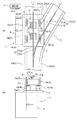
本発明に係る物品搬送設備を適用した天井搬送設備の第1実施形態を、図面に基づいて説明する。本実施形態の天井搬送設備は、ガラス基板製造設備や半導体部品製造設備等に設けられている。このような製造設備では、床面には物品処理装置や物品収納装置が設置されるため、その設置スペースを確保すべく、走行レールを天井から吊下げ状態で配設し、物品搬送車はこのその走行レールに案内されて走行移動する天井搬送車1にて構成されている。図1は、天井搬送車1と、その走行を案内する走行レール2としての一対の走行レール2a、2bとを、天井搬送車1の走行方向視で示した断面図である。走行レール2a、2bは、断面視コ字形で且つ下方が開口したヨーク30の開口側端かつ内壁側に支持される形態で、走行経路に沿って水平方向に離間して一対設けられている。
[First Embodiment]
A first embodiment of a ceiling conveyance facility to which an article conveyance facility according to the present invention is applied will be described based on the drawings. The ceiling conveyance facility of the present embodiment is provided in a glass substrate manufacturing facility, a semiconductor component manufacturing facility, or the like. In such a manufacturing facility, since an article processing device and an article storage device are installed on the floor surface, in order to secure the installation space, the traveling rail is suspended from the ceiling, and the article transport vehicle is It is comprised with the
天井搬送車1は、上記走行レール2a、2b上を走行する走行部5と、走行レール2a、2bの下端よりも下方に突出する形態で走行部5の下方に配設されてかつ物品Bを保持自在な物品保持部8とを備えている。
物品保持部8には、図示しないが、物品Bを把持する把持部や物品を載置する載置部等が備えられており、物品Bを物品保持部8にて保持することができるようになっている。
走行部5は、上記一対の走行レール2a、2bにおける上向きの走行面2u上を転動する一対の走行輪3(走行輪3a、3b)を車体横幅方向に離間して対を成す形態で、かつ、走行方向に間隔を隔てて複数対並ぶ形態で備えている。走行輪3a、3bの夫々は、走行部5に設けられる走行駆動モータM1にて回転駆動されるようになっている。
The
Although not shown, the
The traveling
走行部5と物品保持部8との間は、一対の走行レール2a、2bの間を通過する形態で当該走行部5と物品保持部8とを接続する接続部としての接続部材6が設けられ、接続部材6の下端には、横移動機構付き支持部7が設けられている。
A connecting
横移動機構付き支持部7には、物品保持部8を走行部5に対して車体横幅方向に移動操作自在な横移動機構としてのラックアンドピニオンM2と、スライド移動自在に係合し、かつ、物品保持部8の荷重を支持する荷重支持部材(図示省略)とから構成されている。ラックアンドピニオンM2におけるラックギヤは物品保持部8の上端に取り付けられ、ピニオンギヤは走行部5に対してその水平方向の位置を固定する状態で接続部材6側に設けられ、ピニオンモータによってピニオンギヤを回転させてラックギヤを水平方向に移動させることによって、走行部5に対する物品保持部8の車体横幅方向での位置を、図1に示すように物品保持部8が一対の走行レール2a、2bの中間位置下方に位置する通常走行状態と、図4に示すように物品保持部8が一対の走行レール2a、2bの中間位置下方から車体横幅方向の一方側及び他方側のいずれかに変位した位置に位置する交差部走行状態とするように切換えることができる。
The
走行部5の上端部でかつ車体横幅方向の中央部に、後述するガイドレール31と当接して天井搬送車1の走行を案内する被案内体としての被案内輪9が設けられている。被案内輪9は、走行部5の走行方向において走行輪3の配設位置に対応して、2つずつ設けられ、その2つの被案内輪9が、車体横幅方向にスライド移動自在なスライド体9Sに一体移動自在に、かつ、上下軸心に沿って自由回転自在に取り付けられている。また、走行部5には、スライド体をスライド駆動するスライド体駆動用モータM3が備えられている。
A guided
天井搬送車1には、その作動を制御する制御部Hが設けられている。制御部Hは、例えばマイクロコンピュータにて構成されて走行部5に搭載され、天井搬送設備全体の作動を制御する上位管理装置からの搬送指令を受信して、走行駆動モータM1、ラックアンドピニオンM2におけるラックギヤ、及び、スライド体駆動用モータM3の作動を制御するようになっている。
The
本実施形態において、走行経路は、天井搬送車1が一方向に向けて走行するようになっており、天井搬送車1が複数存在する物品処理装置又は物品収納装置の設置箇所を経由する状態で、かつ、交差部Cとして後述する分岐箇所及び合流箇所を有する状態で設定されている。
In the present embodiment, the traveling route is such that the
交差部Cにおける交差の形態としての分岐箇所は、図2(a)に示すように、天井搬送車1が走行する経路(o)の走行方向前方に経路(i)と経路(ii)の2つの経路が存在するようになっている。また、交差部Cにおける交差の形態としての合流箇所は、図2(b)に示すように、天井搬送車1が走行する経路(i)及び経路(ii)が天井搬送車1の走行方向前方で1つの経路(o)に合流するようになっている。
As shown in FIG. 2 (a), the branching point as the form of intersection at the intersection C is the route (i) and route (ii) 2 in front of the route (o) in which the
他の走行経路である交差経路と交差する交差部Cにおいて、交差経路が位置する側である交差側走行レールは、天井搬送車がその交差部Cを経由して交差経路を走行する場合に接続部材6がその交差側走行レールを通過するために走行方向で分断される。具体的には、図3における走行レール2a及び2d、並びに、図4における走行レール2b及び2cが交差側走行レールに相当し、図3における走行レール2b、及び、図4における走行レール2aが一対の走行レールのうち交差経路が位置しない側である非交差側走行レールに相当する。つまり、交差部Cにおいて、交差側走行レールにはレール不存在区間が形成される。
In an intersection C that intersects an intersection route that is another traveling route, the intersection-side traveling rail that is the side where the intersection route is located is connected when the overhead traveling vehicle travels the intersection route via the intersection C. The
また、交差部Cにおいては、一対の走行レール2の間であってかつ走行レール2の走行面2uよりも上方に離間した位置に、天井搬送車1を選択された走行経路に沿って走行させるべく、走行部5が備える被案内輪9に当接して走行部5の走行を案内する案内部としてのガイドレール31が設けられている。ここで、選択された走行経路とは、上位管理装置からの搬送指令に従って搬送元箇所から搬送先箇所まで物品Bを搬送すべく決定された走行経路であり、分岐箇所または合流箇所においては、上記のように決定された走行経路ではない他の走行経路が交差経路となる。つまり、図2(a)において経路(o)から経路(i)が走行経路として選択された場合には、経路(ii)が交差経路となり、経路(o)から経路(ii)が走行経路として選択された場合には、経路(i)が交差経路となる。また、図2(b)において経路(i)から経路(o)が走行経路として選択された場合には、経路(ii)が交差経路となり、経路(ii)から経路(o)が走行経路として選択された場合には、経路(i)が交差経路となる。
Further, at the intersection C, the
ガイドレール31は、天井搬送車1の走行方向視において断面形状がT字形に形成されている。すなわち、ガイドレール31は、図1に示すように、天井面や支持面に取り付けるための水平部と、被案内輪9に当接して当該被案内輪9を案内する垂直面である第1案内面31a及び第2案内面31bを備えた垂直部とから構成されている。垂直部は、交差部Cにおいて夫々の走行経路に沿う状態で配設されている。
The
交差部Cにおいて、走行経路において主経路と分岐経路とに分岐又は合流する場合には、天井搬送車1の作動を制御する制御部Hは、スライド体駆動用モータM3を作動させて被案内輪9を図3又は図4に示すように車体横幅方向に移動させる。
At the intersection C, when the travel route branches or merges into the main route and the branch route, the control unit H that controls the operation of the
以下、交差部Cではない箇所、及び、交差部Cの一例として分岐箇所を天井搬送車1が走行する場合における制御部Hによる制御を説明する。
制御部Hは、天井搬送車1を車体横幅方向に一対の走行輪3の双方が走行レール2に載置支持される状態で走行させる場合には、図1に示す通常走行状態とすべく、ラックアンドピニオンM2におけるラックギヤを制御する。
Hereinafter, the control by the control unit H in the case where the
When the control unit H causes the
また、図3(a)に示すように、天井搬送車1を経路(ii)に沿って走行させるべく交差部Cを通過させる場合には、制御部Hは、被案内輪9をガイドレール31における垂直部の右側(第2案内面31b側)に位置させるべく移動させる。これにより、走行部5は、ガイドレール31における第2案内面31bと被案内輪9とが当接する状態で経路(ii)に向けて案内されるとともに、ガイドレール31が被案内輪9を介して荷重を受止めて案内支持することで、走行部5が非交差側走行レール2bから脱落することを抑制する形態で走行することができる。
In addition, as shown in FIG. 3A, when passing the intersection C so that the
このとき、制御部Hは、ラックアンドピニオンM2におけるラックギヤを作動させて、物品保持部8を、一対の走行レール2の中間位置(通常走行時位置と称する)から車体横幅方向で交差側走行レール2a又は2dから遠ざかる側に位置させた交差部走行状態とすべくラックアンドピニオンM2におけるラックギヤを制御する(図3(b)参照)。
また、制御部Hは、複数の被案内輪9のうちの1つがガイドレール31に案内される状態を検出した時点でラックアンドピニオンM2の変位量増加方向への作動を開始させて、天井搬送車1がレール不存在区間を走行するときに物品保持部8の通常走行時位置からの車体横幅方向での変位量が最大となるようにラックアンドピニオンM2を制御する。さらに、制御部Hは、複数の被案内輪9のうちの全てがガイドレール31に案内されない状態を検出した時点でラックアンドピニオンM2の変位量減少方向への作動を開始させるようにラックアンドピニオンM2を制御する。
At this time, the control unit H operates the rack gear in the rack and pinion M2 to move the
Moreover, the control part H starts the operation | movement to the displacement amount increase direction of the rack and pinion M2 at the time of detecting the state by which one of the to-
また、図4(a)に示すように、天井搬送車1を経路(i)に沿って走行させるべく交差部Cを通過させる場合には、制御部Hは、被案内輪9をガイドレール31における垂直部の左側(第1案内面31a側)に位置させるべく移動させる。これにより、走行部5は、ガイドレール31の第1案内面31aと被案内輪9とが当接する状態で経路(i)に向けて案内されるとともに、ガイドレール31が被案内輪9を介して荷重を受止めて案内支持することで、走行部5が非交差側走行レール2aから脱落することを抑制する形態で走行することができる。
In addition, as shown in FIG. 4A, when passing the crossing portion C so that the
このとき、制御部Hは、ラックアンドピニオンM2におけるラックギヤを作動させて、物品保持部8を、一対の走行レール2の中間位置から車体横幅方向で非交差側走行レール2b又は2cから遠ざかる側に位置させた交差部走行状態とすべくラックアンドピニオンM2におけるラックギヤを制御する(図4(b)参照)。
At this time, the control unit H operates the rack gear in the rack and pinion M2, and moves the
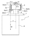
図5に示すように、交差部Cにおいて物品保持部8を交差部走行状態とした場合は、天井搬送車1の重心Wが走行輪3aの直下方に位置する状態となる。このとき被案内輪9がガイドレール31を押圧する力をF1にて示す。
また、図6には、本実施形態では現出しない状態であるが、比較例として、交差部Cにおいて物品保持部8を交差部走行状態としなかった場合を示す。この場合には、天井搬送車1の重心Wは走行方向視で車体横幅方向の中央寄りに位置する状態となっている。このとき被案内輪9がガイドレール31を押圧する力をF2にて示す。
As shown in FIG. 5, when the
FIG. 6 shows a case where the
図5及び図6より分かるように、交差部Cにおいて物品保持部8を交差部走行状態とした場合に被案内輪9がガイドレール31を押圧する力F1は、交差部Cにおいて物品保持部8を交差部走行状態としなかった場合に被案内輪9がガイドレール31を押圧する力F2よりも十分に小さくなる。
つまり、交差部Cにおいては物品保持部8を交差部走行状態とすることにより、走行方向視で走行輪3aが走行レール2aと当接する箇所を中心としたモーメントを小さくして、被案内輪9がガイドレール31における第1案内面31aを押圧する力を小さくすることができる。
As can be seen from FIGS. 5 and 6, the force F <b> 1 that the guided
In other words, at the intersection C, the
〔第2実施形態〕
次に、本発明に係る物品搬送設備を適用した天井搬送設備の第2実施形態を説明するが、第2実施形態は、第1実施形態と同様の天井搬送設備における案内部と被案内体の構成が異なるのみであるため、その相違点について説明を加え、重複する部分については説明を省略する。
[Second Embodiment]
Next, a second embodiment of a ceiling transport facility to which the article transport facility according to the present invention is applied will be described. The second embodiment is a guide unit and a guided body in a ceiling transport facility similar to the first embodiment. Since only the configuration is different, the difference will be described, and the description of overlapping parts will be omitted.
図7は、第2実施形態における物品搬送車としての天井搬送車1と、その走行を案内する走行レール2としての一対の走行レール2a、2bとを、天井搬送車1の走行方向視で示した図である。走行レール2a、2bは、断面視コ字形で且つ下方が開口したヨーク40の開口側端部に支持される形態で、走行経路に沿って水平方向に離間して一対設けられている。また、走行レール2a、2b夫々の外側面には、後述する被案内体としての一対の被案内輪9a、9bと当接する案内部としての案内面40a、40bが形成されている。
FIG. 7 shows a
第2実施形態では、図7に示すように、接続部材6の下端に設けられる横移動機構付き支持部7の天井搬送車1の走行方向視での両端部が、走行輪3a、3bが走行レール2a、2bに載置支持された状態において案内面40a、40bよりも外方側に位置するように形成されている。横移動機構付き支持部7の車体横幅方向両端部には、被案内輪9a、9bを上昇位置と下降位置に操作自在なソレノイド機構M4が各別に設けられている。ソレノイド機構M4にて被案内輪9a又は9bが上昇位置に操作されると、被案内輪9a又は9bは、案内面40a又は40bと当接する状態となり、被案内輪9a又は9bが下降位置に操作されると、被案内輪9a又は9bは案内面40a又は40bから離間し、走行レール2a、2b及びヨーク40の下端よりも下方に位置する状態となる。
In the second embodiment, as shown in FIG. 7, both ends of the
また、第2実施形態では、制御部Hは、天井搬送設備全体の作動を制御する上位管理装置からの指令情報を受信して、走行駆動モータM1、ラックアンドピニオンM2におけるラックギヤ、及び、ソレノイド機構M4の作動を制御するようになっている。 Moreover, in 2nd Embodiment, the control part H receives the command information from the high-order management apparatus which controls the action | operation of the whole ceiling conveyance installation, the rack gear in the traveling drive motor M1, the rack and pinion M2, and the solenoid mechanism The operation of M4 is controlled.
以下、交差部Cではない箇所、及び、交差部Cの一例として分岐箇所を天井搬送車1が走行する場合における制御部Hによる制御を説明する。
制御部Hは、天井搬送車1を車体横幅方向に一対の走行輪3の双方が走行レール2a、2bに載置支持される状態で走行させる場合には、図7に示すように、被案内輪9a又は9b双方が上昇位置となるようにソレノイド機構M4を操作し、且つ、物品保持部8を通常走行状態とすべくラックアンドピニオンM2におけるラックギヤを制御する。
Hereinafter, the control by the control unit H in the case where the
As shown in FIG. 7, the controller H guides the overhead guided
また、天井搬送車1を、交差部Cを通過させて走行させる場合(第1実施形態における図4のように経路(i)を走行する場合を例として説明する)には、図8に示すように、制御部Hは、被案内輪9aを上昇位置とし、被案内輪9bを下降位置とすべくソレノイド機構M4を操作する。これにより、天井搬送車1は一対の走行レールのうち非交差側走行レール2aに沿って走行する。また、被案内輪9bは走行レール2bの下方に位置するので、走行輪3bは交差側走行レール2bから離れることができる。このように走行輪3aのみが非交差側走行レール2aに載置支持され、走行輪3bは走行レール2に載置支持されない状態となるため、天井搬送車1には、走行方向視で走行輪3aと走行レール2aとが当接する箇所を中心としたモーメントが生じることになる。そして、生じたモーメントを被案内輪9aが案内面40aを押圧する力によって支持することになる。すなわち、天井搬送車1が交差部Cを通過する場合には、案内面40aが被案内輪9aを案内支持することで走行部5が非交差側走行レール2aから脱落することを抑制する形態で走行するように構成されている。
Further, in the case where the
このとき、制御部Hは、ラックアンドピニオンM2におけるラックギヤを作動させて、物品保持部8を、一対の走行レール2の中間位置から車体横幅方向で交差側走行レール2b又は2cから遠ざかる側に位置させた交差部走行状態とすべくラックアンドピニオンM2におけるラックギヤを制御する。
At this time, the control unit H operates the rack gear in the rack and pinion M2 to position the
なお、図示は省略するが、第1実施形態における図3の如く経路(ii)を走行する場合には、制御部Hは、被案内輪9bを上昇位置とし、被案内輪9aを下降位置とすべくソレノイド機構M4を操作する。これにより、天井搬送車1は一対の走行レールのうち非交差側走行レール2bに沿って走行する。また、被案内輪9aは走行レール2aの下方に位置するので、走行輪3aは走行レール2aから離れることができる。このように走行輪3bのみが非交差側走行レール2bに載置支持され、走行輪3aは走行レール2に載置支持されない状態となるため、天井搬送車1には、走行方向視で走行輪3bと走行レール2bとが当接する箇所を中心としたモーメントが生じることになる。そして、生じたモーメントを被案内輪9bが案内面40bを押圧する力によって支持することになる。すなわち、天井搬送車1が、交差部Cを通過する場合には、案内面40bが被案内輪9bを案内支持することで走行部5が非交差側走行レール2bから脱落することを抑制する形態で走行するように構成されている。
Although illustration is omitted, when traveling on the route (ii) as shown in FIG. 3 in the first embodiment, the control unit H sets the guided
このとき、制御部Hは、ラックアンドピニオンM2におけるラックギヤを作動させて、物品保持部8を、一対の走行レール2の中間位置から車体横幅方向で交差側走行レール2a又は2dから遠ざかる側に位置させた交差部走行状態とすべくラックアンドピニオンM2におけるラックギヤを制御する。
At this time, the control unit H operates the rack gear in the rack and pinion M2 to position the
図8に示すように、交差部Cにおいて物品保持部8を交差部走行状態とした場合は、天井搬送車1の重心Wが走行輪3aの直下方に位置する状態となる。このとき被案内輪9aが案内面40aを押圧する力をF1にて示す。
また、図9には、本実施形態では現出しない状態であるが、比較例として、交差部Cにおいて物品保持部8を交差部走行状態としなかった場合を示す。この場合には、天井搬送車1の重心Wは走行方向視で車体横幅方向の中央寄りに位置する状態となっている。このとき被案内輪9aが案内面40aを押圧する力をF2にて示す。
As shown in FIG. 8, when the
FIG. 9 shows a state in which the
図8及び図9より分かるように、交差部Cにおいて物品保持部8を交差部走行状態とした場合に被案内輪9aが案内面40aを押圧する力F1は、交差部Cにおいて物品保持部8を交差部走行状態としなかった場合に被案内輪9aが案内面40aを押圧する力F2よりも十分に小さくなる。
つまり、交差部Cにおいては物品保持部8を交差部走行状態とすることにより、走行輪3aが走行レール2aと当接する箇所を中心としたモーメントを小さくして、被案内輪9aが案内面40aを押圧する力を小さくすることができる。
As can be seen from FIGS. 8 and 9, the force F <b> 1 that the guided
In other words, at the intersection C, the
〔別実施形態〕
(1)上記第1及び第2実施形態では、本発明の物品搬送設備を、天井から吊下げ状態で配設した走行レール上を走行する天井搬送車を備えた天井搬送設備に適用した構成を例として説明したが、走行レールを床面上に立設した支持体に支持させたり、壁面から突設された支持体に支持させる構成としてもよい。また、上記第1及び第2実施形態では、本発明の物品搬送設備をガラス基盤製造設備や半導体部品製造設備において用いる例を説明したが、本発明の物品搬送設備は、例示した上記以外の製造設備や収納設備等に用いてもよい。
[Another embodiment]
(1) In the said 1st and 2nd embodiment, the structure which applied the article conveyance equipment of this invention to the ceiling conveyance equipment provided with the ceiling conveyance vehicle which drive | works on the traveling rail arrange | positioned in the suspended state from the ceiling. Although described as an example, the traveling rail may be supported by a support standing on the floor or supported by a support protruding from the wall surface. Moreover, although the said 1st and 2nd embodiment demonstrated the example which uses the article conveyance equipment of this invention in a glass substrate manufacturing equipment or a semiconductor component manufacturing equipment, the goods conveyance equipment of this invention is manufacture other than the above illustrated. You may use for an installation, storage facilities, etc.
(2)上記第1及び第2実施形態では、交差部Cにおいて物品保持部8を交差部走行状態とするに当たり、天井搬送車1の重心Wが走行輪3aの直下方に位置する状態となるようにラックアンドピニオンM2を移動操作する構成を例示したが、天井搬送車1の重心Wは、走行方向視で車体横幅方向の中央よりも非交差側走行レール寄りの位置となっていればよい。また、上記第1及び第2実施形態では、接続部材6の下端に設けられる横移動機構付き支持部7に横移動機構としてのラックアンドピニオンM2を備え、物品保持部8の接続部材6に対しての車体横幅方向での位置を移動操作する構成としたが、このような構成に限定されるものではなく、走行部5に対して接続部材6の車体横幅方向での位置を移動操作する構成としてもよい。
(2) In the first and second embodiments, when the
また、上記第1及び第2実施形態では、横移動機構としてラックアンドピニオンM2を備える構成としたが、例えば、物品保持部8に物品Bを車体横幅方向で移載する移載機構が備えられている場合には、その移載機構を用いて物品Bの車体横幅方向の位置を変位させる構成としてもよい。
In the first and second embodiments, the rack and pinion M2 is provided as the lateral movement mechanism. However, for example, a transfer mechanism for transferring the article B to the
さらに、制御部Hが天井搬送車1又は物品保持部8の重量を検出して管理し、かつ、ラックアンドピニオンM2の移動操作量(物品保持部8の移動距離)を、天井搬送車1の重量又は物品保持部8が保持している物品Bの重量が小さいときには小さな移動操作量とし、天井搬送車1の重量又は物品保持部8が保持している物品Bの重量が大きいときには大きな移動操作量とするように制御する構成としてもよい。
さらに、制御部Hが天井搬送車1の走行速度を検出し、天井搬送車1の走行速度によってラックアンドピニオンM2の移動操作量(物品保持部8の移動距離)を異ならせるように制御する構成としてもよい。
Furthermore, the control unit H detects and manages the weight of the
Further, the control unit H detects the traveling speed of the
(3)上記第1又は第2実施形態では、制御部Hを走行部5に装備させ、上位管理装置からの指令情報を受信して天井搬送車1の作動を制御する構成を説明したが、このような構成に限定されるものではなく、例えば、制御部Hを走行部5以外(例えば地上側)に備え、走行部5には制御部Hからの指令情報を受信する受信部のみを備えて、受信した指令情報に従って、走行駆動モータM1、ラックアンドピニオンM2におけるラックギヤ、及び、スライド体駆動用モータM3又はソレノイド機構M4を駆動させるように構成してもよい。また、走行部5に設ける制御部Hの自律判断によって、走行駆動モータM1、ラックアンドピニオンM2におけるラックギヤ、及び、スライド体駆動用モータM3又はソレノイド機構M4を駆動させるように構成してもよい。
(3) In the first or second embodiment, the configuration in which the control unit H is installed in the traveling
(4)上記第1実施形態では、被案内輪9をスライド体9Sに支持させて、スライド体9Sをスライド操作することで被案内輪9の車体横幅方向の位置を変更する構成を説明したが、このような構成に限定されるものではなく、例えば、被案内輪9に代えて摩擦抵抗の小さい当接体をスライド体9Sに取付け、ガイドレール31と当該当接体を当接さる構成としてもよい。また、被案内輪9を水平面内で揺動自在なアームに上下軸心で回転自在に取付け、アームの揺動により被案内輪9の車体横幅方向の位置を変更操作するように構成してもよい。
(4) In the first embodiment, the configuration has been described in which the guided
また、上記第1又は第2実施形態では、被案内輪9を、車体横幅方向に一対の走行輪3に対応して2個設ける構成としたが、一対の走行輪3に対応して1個または3個以上の被案内輪9を設ける構成としてもよく、また、被案内輪9を、車体横幅方向に一対の走行輪3に対応して設けるのではなく、走行部5に対応して1個以上の任意の個数の被案内輪9を設けるようにしてもよい。
In the first or second embodiment, two guided
(5)上記第1又は第2実施形態では、天井搬送車1の走行部5を単一の躯体部として構成し、天井搬送車1の走行方向に複数対備えられる走行輪3の全てを、当該単一の躯体部に配設する構成を例示したが、このような構成に限定されるものではなく、例えば、車体横幅方向に一対の走行輪3を一組備えかつ上下軸心回りで回動自在な躯体部を、天井搬送車1の走行方向に複数備え、それらを相互に接続する構成としてもよい。この場合、複数の躯体部が走行部5となる。
(5) In the first or second embodiment, the traveling
(6)上記第1又は第2実施形態では、天井搬送車1が複数の経路間で乗り移ることが可能な分岐経路又は合流経路を交差部Cとして例示したが、交差部Cとしては、天井搬送車1が複数の経路間で乗り移りできない十字交差路(平面視で直角に交差しているものに限定されない)も含まれる。この場合を図10に示す。経路(o)及び経路(i)を走行経路として天井搬送車1が走行する場合、天井搬送車1は経路(x)又は経路(ii)には乗り移ることができない。この場合、経路(o)と経路(i)との間において、左右一対の走行レール2の双方において走行レール2が存在しないレール不存在区間が生じるため、走行部の車体横幅方向に対をなす走行輪3の双方が走行レール2に載置支持されない状態が生じてしまう。そこで、天井搬送車1の走行経路となる経路(o)及び経路(i)の間において、左右一対の走行レール2の一方に、交差部用走行レール2rを現出させるように構成する。また、この交差部用走行レール2rと平面視で並行となるように交差部用ガイドレール31rを現出させるように構成する。これにより、天井搬送車1は、十字交差路においても対をなして設けられる走行輪3の双方が走行レール2に載置支持されている場合と同じ姿勢に保って、交差部を通過することができる。
(6) In the first or second embodiment, the branching path or the merging path in which the
(7)上記第1又は第2実施形態では、横移動機構としてラックアンドピニオンM2を用いる構成としたが、このような構成に限定されるものではなく、例えばボールネジやスカラアーム等、走行部5に対して物品保持部8を車体横幅方向に移動操作可能な各種の機構を用いることができる。
(7) In the first or second embodiment, the rack and pinion M2 is used as the lateral movement mechanism. However, the configuration is not limited to such a configuration, and the traveling
(8)上記第1又は第2実施形態では、一対の走行レール2を水平方向で互いに離間した状態でかつヨーク30又はヨーク40に支持される状態で配設する構成を例示したが、このような構成に限定されるものではなく、例えば、断面視コの字状でかつ下端に走行レール2に相当する一対のレール部分を一体に形成する形態で、押出形成等の適切な形成方法によって長尺状に形成されるレール材を用いる構成としてもよい。
また、上記第1又は第2実施形態では、一対のレール2の支持形態として、ヨーク30又は40の下端部に一対のレール2の夫々を支持する構成としたが、一対のレール2の間隔を適切に保つ状態で支持できる構成であれば、上述のようにヨークに支持させる形態に限らず、各種の支持形態を適用することができる。
(8) In the first or second embodiment, the configuration in which the pair of traveling
Moreover, in the said 1st or 2nd embodiment, it was set as the structure which supports each of a pair of
(9)上記第2実施形態では、被案内輪9a、9bを上昇または下降操作するためにソレノイド機構M4を用いる構成を例示したが、このような構成に代えて、例えば、ラックアンドピニオンやボールネジ等の各種の直線移動操作機構を用いることができる。
(9) In the second embodiment, the configuration in which the solenoid mechanism M4 is used to raise or lower the guided
1 物品搬送車
2 走行レール
2u 走行面
3 走行輪
5 走行部
6 接続部
8 物品保持部
9 被案内体
31 案内部
B 物品
M2 横移動機構
H 制御部
DESCRIPTION OF
Claims (2)
前記走行部は、前記一対の走行レールにおける上向きの走行面上を転動する走行輪を車体横幅方向に離間して対を成す形態でかつ走行方向に間隔を隔てて複数対並ぶ形態で備え、
他の走行経路である交差経路と交差する交差部が前記走行経路に設定され、
前記一対の走行レールのうち前記交差経路が位置する側である交差側走行レールは、前記物品搬送車が前記交差部を経由して前記交差経路を走行する場合に前記中間部がその交差側走行レールを通過するレール不存在区間を形成するように、走行方向で分断されており、
前記交差部には、前記物品搬送車を選択された走行経路に沿って走行させるべく、前記走行部が備える被案内体に当接して前記走行部の走行を案内する案内部が設けられ、
前記物品搬送車が、前記交差部を通過する場合には、前記案内部が前記被案内体を案内支持することで前記走行部が前記一対の走行レールのうち前記交差経路が位置しない側である非交差側走行レールから脱落することを抑制する形態で走行するように構成されている物品搬送設備であって、
前記物品搬送車は、前記物品保持部を前記走行部に対して車体横幅方向に移動操作する横移動機構を備え、
前記物品搬送車の作動を制御する制御部が、前記物品搬送車を前記交差部以外で走行させる場合は前記物品保持部が前記一対の走行レールの中間位置下方に位置する通常走行状態とし、かつ、前記物品搬送車を前記交差部で走行させる場合は前記物品保持部が前記一対の走行レールの前記中間位置下方から車体横幅方向で前記交差側走行レールから遠ざかる側に位置させた交差部走行状態とするべく、前記横移動機構の作動を制御するように構成されている物品搬送設備。 An article transport vehicle that can travel along a travel path projects above a pair of travel rails disposed along the travel path above the floor and below the lower end of the travel rail. An article holding portion disposed below the traveling portion and capable of holding an article in a form, and configured in a form in which an intermediate portion in the vertical direction is positioned between the pair of traveling rails,
The traveling unit includes a pair of traveling wheels that roll on an upward traveling surface of the pair of traveling rails, separated in the lateral direction of the vehicle body, and arranged in pairs with an interval in the traveling direction.
An intersection that intersects an intersection route that is another route is set as the route,
Of the pair of travel rails, the crossing travel rail that is the side on which the crossing route is located is such that the intermediate portion travels on the crossing side when the article transport vehicle travels on the crossing route via the intersection. It is divided in the running direction so as to form a rail-free section that passes through the rail,
The crossing portion is provided with a guide portion that contacts the guided body provided in the traveling portion and guides the traveling of the traveling portion in order to cause the article transport vehicle to travel along the selected traveling route.
When the article transport vehicle passes through the intersecting portion, the guide portion guides and supports the guided body so that the traveling portion is on the side where the intersecting route is not located in the pair of traveling rails. It is an article transport facility configured to travel in a form that suppresses falling off from the non-crossing traveling rail,
The article transport vehicle includes a lateral movement mechanism that operates the article holding unit to move in the vehicle lateral width direction with respect to the traveling unit.
When the control unit that controls the operation of the article transporting vehicle causes the article transporting vehicle to travel at a position other than the intersection, the article holding unit is in a normal traveling state located below an intermediate position of the pair of traveling rails, and In the case where the article transport vehicle is caused to travel at the intersection, the article holding portion is located on the side away from the intersection traveling rail in the lateral direction of the vehicle body from below the intermediate position of the pair of traveling rails. Therefore, an article conveyance facility configured to control the operation of the lateral movement mechanism.
前記横移動機構が、前記接続部に対して前記物品保持部を車体横幅方向に移動操作するように構成されている請求項1に記載の物品搬送設備。 A connecting portion for connecting the traveling portion and the article holding portion in a form passing between the pair of traveling rails is provided, and a part or all of the connecting portion in the vertical direction corresponds to the intermediate portion;
The article transporting facility according to claim 1, wherein the lateral movement mechanism is configured to move the article holding section in a vehicle lateral width direction with respect to the connection section.
Priority Applications (4)
| Application Number | Priority Date | Filing Date | Title |
|---|---|---|---|
| JP2012134197A JP5590422B2 (en) | 2012-06-13 | 2012-06-13 | Goods transport equipment |
| TW102115877A TWI564196B (en) | 2012-06-13 | 2013-05-03 | Article transport facility |
| KR1020130057725A KR102023519B1 (en) | 2012-06-13 | 2013-05-22 | Article transport facility |
| CN201310225282.0A CN103481893B (en) | 2012-06-13 | 2013-06-07 | Article transport facility |
Applications Claiming Priority (1)
| Application Number | Priority Date | Filing Date | Title |
|---|---|---|---|
| JP2012134197A JP5590422B2 (en) | 2012-06-13 | 2012-06-13 | Goods transport equipment |
Publications (2)
| Publication Number | Publication Date |
|---|---|
| JP2013256235A JP2013256235A (en) | 2013-12-26 |
| JP5590422B2 true JP5590422B2 (en) | 2014-09-17 |
Family
ID=49822606
Family Applications (1)
| Application Number | Title | Priority Date | Filing Date |
|---|---|---|---|
| JP2012134197A Active JP5590422B2 (en) | 2012-06-13 | 2012-06-13 | Goods transport equipment |
Country Status (4)
| Country | Link |
|---|---|
| JP (1) | JP5590422B2 (en) |
| KR (1) | KR102023519B1 (en) |
| CN (1) | CN103481893B (en) |
| TW (1) | TWI564196B (en) |
Families Citing this family (24)
| Publication number | Priority date | Publication date | Assignee | Title |
|---|---|---|---|---|
| JPS58103920A (en) * | 1981-12-16 | 1983-06-21 | Sumitomo Light Metal Ind Ltd | Manufacture of metallic double pipe |
| JP6276090B2 (en) * | 2014-03-31 | 2018-02-07 | 株式会社ダイヘン | Transport device, transport system |
| JP6237493B2 (en) | 2014-06-25 | 2017-11-29 | マツダ株式会社 | Parts assembly device |
| CN104401331B (en) * | 2014-11-27 | 2015-10-07 | 无锡桑尼安科技有限公司 | Cable car crane automation control system |
| CN104816729B (en) * | 2014-11-27 | 2016-01-20 | 杨巧霞 | A kind of cable car crane automation control method |
| JP6168477B2 (en) * | 2015-03-31 | 2017-07-26 | 村田機械株式会社 | Traveling cart system and traveling method of traveling cart |
| JP6471651B2 (en) * | 2015-08-27 | 2019-02-20 | 株式会社ダイフク | Goods transport equipment |
| CN106608595A (en) | 2015-10-26 | 2017-05-03 | 鹰铁路集装箱物流有限责任公司 | Carrier configured to transport various sized objects |
| CN106956940A (en) * | 2015-10-26 | 2017-07-18 | 鹰铁路集装箱物流有限责任公司 | Overhead system is transported and route management system |
| KR102478040B1 (en) * | 2016-03-09 | 2022-12-15 | 세메스주식회사 | Apparatus for transferring using the integrated circuit device fabricating |
| CN106429285B (en) * | 2016-08-30 | 2018-09-14 | 昆山佰奥智能装备股份有限公司 | Automate streamline mechanism |
| CN106241326B (en) * | 2016-08-30 | 2018-09-14 | 昆山佰奥智能装备股份有限公司 | Automate streamline transmission method |
| JP6620707B2 (en) * | 2016-09-09 | 2019-12-18 | 株式会社ダイフク | Goods transport equipment |
| JP6790719B2 (en) * | 2016-10-26 | 2020-11-25 | 村田機械株式会社 | Drive trolley |
| JP6677187B2 (en) * | 2017-01-31 | 2020-04-08 | 株式会社ダイフク | Goods transport equipment |
| JP6717243B2 (en) * | 2017-03-14 | 2020-07-01 | 株式会社ダイフク | Goods transport facility |
| CN108328240B (en) * | 2018-04-13 | 2023-06-09 | 浙江衣拿智能科技股份有限公司 | Goods shelf transfer device of conveying system |
| JP7099245B2 (en) * | 2018-10-19 | 2022-07-12 | 株式会社ダイフク | Goods carrier |
| SG11202104305YA (en) * | 2018-10-29 | 2021-05-28 | Murata Machinery Ltd | Ceiling conveyance vehicle and ceiling conveyance vehicle system |
| CN109435968B (en) * | 2018-12-29 | 2024-07-23 | 中车长江车辆有限公司 | Container transportation equipment |
| CN109435969B (en) * | 2018-12-29 | 2024-07-23 | 中车长江车辆有限公司 | Container transportation equipment |
| CN113247561B (en) * | 2021-06-09 | 2021-12-21 | 合肥井松智能科技股份有限公司 | Heavy EMS (energy management system) for automatic metallurgical industry |
| CN114132701B (en) * | 2021-11-26 | 2024-01-30 | 苏州泰科贝尔直驱电机有限公司 | Transfer equipment and transfer method thereof |
| CN116453993B (en) * | 2023-06-15 | 2023-09-08 | 上海果纳半导体技术有限公司 | Crown block transporting system, crown block transporting method, and storable medium |
Family Cites Families (6)
| Publication number | Priority date | Publication date | Assignee | Title |
|---|---|---|---|---|
| JPH0687436A (en) * | 1992-09-04 | 1994-03-29 | Murata Mach Ltd | Article transporting device |
| JP4483055B2 (en) * | 2000-09-14 | 2010-06-16 | 株式会社ダイフク | Transport equipment |
| US6629502B2 (en) * | 2000-09-14 | 2003-10-07 | Daifuku Co., Ltd. | Conveyance system |
| KR100520061B1 (en) * | 2002-12-06 | 2005-10-11 | 삼성전자주식회사 | Overhead Transport Apparatus |
| TW200524803A (en) * | 2003-11-13 | 2005-08-01 | Applied Materials Inc | Stabilizing substrate carriers during overhead transport |
| JP5151276B2 (en) * | 2007-07-04 | 2013-02-27 | 村田機械株式会社 | Transport system |
-
2012
- 2012-06-13 JP JP2012134197A patent/JP5590422B2/en active Active
-
2013
- 2013-05-03 TW TW102115877A patent/TWI564196B/en active
- 2013-05-22 KR KR1020130057725A patent/KR102023519B1/en active IP Right Grant
- 2013-06-07 CN CN201310225282.0A patent/CN103481893B/en active Active
Also Published As
| Publication number | Publication date |
|---|---|
| CN103481893B (en) | 2017-04-12 |
| TWI564196B (en) | 2017-01-01 |
| TW201400389A (en) | 2014-01-01 |
| CN103481893A (en) | 2014-01-01 |
| JP2013256235A (en) | 2013-12-26 |
| KR20130139767A (en) | 2013-12-23 |
| KR102023519B1 (en) | 2019-09-20 |
Similar Documents
| Publication | Publication Date | Title |
|---|---|---|
| JP5590422B2 (en) | Goods transport equipment | |
| KR102422207B1 (en) | Article transport facility | |
| EP3705422B1 (en) | Conveyance system | |
| JP6665938B2 (en) | Tracked bogie system and tracked bogie | |
| JP5527619B2 (en) | Ceiling-mounted goods transport equipment | |
| EP1868236B1 (en) | Overhead traveling vehicle system and transportation method using the same | |
| JP6946965B2 (en) | Transport system | |
| JP6168476B2 (en) | Transport cart and transport cart system | |
| JP5477651B2 (en) | Goods transport equipment | |
| KR101419356B1 (en) | Carrier and overhead hoist system including the same | |
| KR101521498B1 (en) | Rail car and overhead hoist shuttle or transport system using the same | |
| KR101479941B1 (en) | Rail car | |
| KR101419359B1 (en) | Rail car and overhead hoist shuttle or transport system using the same | |
| KR101419358B1 (en) | Overhead hoist system | |
| KR102451691B1 (en) | driving vehicle system | |
| KR101504145B1 (en) | Overhead hoist system and carrier thereof | |
| KR101419357B1 (en) | Overhead hoist system | |
| KR101396226B1 (en) | Overhead hoist system |
Legal Events
| Date | Code | Title | Description |
|---|---|---|---|
| A621 | Written request for application examination |
Free format text: JAPANESE INTERMEDIATE CODE: A621 Effective date: 20140220 |
|
| A977 | Report on retrieval |
Free format text: JAPANESE INTERMEDIATE CODE: A971007 Effective date: 20140619 |
|
| TRDD | Decision of grant or rejection written | ||
| A01 | Written decision to grant a patent or to grant a registration (utility model) |
Free format text: JAPANESE INTERMEDIATE CODE: A01 Effective date: 20140703 |
|
| A61 | First payment of annual fees (during grant procedure) |
Free format text: JAPANESE INTERMEDIATE CODE: A61 Effective date: 20140716 |
|
| R150 | Certificate of patent or registration of utility model |
Ref document number: 5590422 Country of ref document: JP Free format text: JAPANESE INTERMEDIATE CODE: R150 |
|
| R250 | Receipt of annual fees |
Free format text: JAPANESE INTERMEDIATE CODE: R250 |
|
| R250 | Receipt of annual fees |
Free format text: JAPANESE INTERMEDIATE CODE: R250 |
|
| R250 | Receipt of annual fees |
Free format text: JAPANESE INTERMEDIATE CODE: R250 |
|
| R250 | Receipt of annual fees |
Free format text: JAPANESE INTERMEDIATE CODE: R250 |
|
| R250 | Receipt of annual fees |
Free format text: JAPANESE INTERMEDIATE CODE: R250 |
|
| R250 | Receipt of annual fees |
Free format text: JAPANESE INTERMEDIATE CODE: R250 |
|
| R250 | Receipt of annual fees |
Free format text: JAPANESE INTERMEDIATE CODE: R250 |
|
| R250 | Receipt of annual fees |
Free format text: JAPANESE INTERMEDIATE CODE: R250 |