JP5582619B2 - Flexible nerve position determination device - Google Patents
Flexible nerve position determination device Download PDFInfo
- Publication number
- JP5582619B2 JP5582619B2 JP2011554269A JP2011554269A JP5582619B2 JP 5582619 B2 JP5582619 B2 JP 5582619B2 JP 2011554269 A JP2011554269 A JP 2011554269A JP 2011554269 A JP2011554269 A JP 2011554269A JP 5582619 B2 JP5582619 B2 JP 5582619B2
- Authority
- JP
- Japan
- Prior art keywords
- nerve
- region
- stimulation
- nlr
- tissue
- Prior art date
- Legal status (The legal status is an assumption and is not a legal conclusion. Google has not performed a legal analysis and makes no representation as to the accuracy of the status listed.)
- Expired - Fee Related
Links
- 210000005036 nerve Anatomy 0.000 title claims description 413
- 230000000638 stimulation Effects 0.000 claims description 227
- 239000004020 conductor Substances 0.000 claims description 35
- 230000001537 neural effect Effects 0.000 claims description 34
- 239000003550 marker Substances 0.000 claims description 31
- 230000004913 activation Effects 0.000 claims description 8
- 238000004891 communication Methods 0.000 claims description 7
- 210000001519 tissue Anatomy 0.000 description 375
- 230000006872 improvement Effects 0.000 description 118
- 238000000034 method Methods 0.000 description 113
- 230000004044 response Effects 0.000 description 44
- 230000004807 localization Effects 0.000 description 38
- 238000012986 modification Methods 0.000 description 38
- 230000004048 modification Effects 0.000 description 38
- 210000003205 muscle Anatomy 0.000 description 30
- 239000000523 sample Substances 0.000 description 20
- 230000001965 increasing effect Effects 0.000 description 18
- 230000006837 decompression Effects 0.000 description 16
- 230000003213 activating effect Effects 0.000 description 15
- 230000004936 stimulating effect Effects 0.000 description 15
- 230000007383 nerve stimulation Effects 0.000 description 14
- 210000000988 bone and bone Anatomy 0.000 description 12
- 210000000746 body region Anatomy 0.000 description 11
- 230000008878 coupling Effects 0.000 description 11
- 238000010168 coupling process Methods 0.000 description 11
- 238000005859 coupling reaction Methods 0.000 description 11
- 239000000463 material Substances 0.000 description 11
- 238000005259 measurement Methods 0.000 description 11
- 238000001356 surgical procedure Methods 0.000 description 10
- 230000006378 damage Effects 0.000 description 9
- 238000002594 fluoroscopy Methods 0.000 description 9
- 210000000278 spinal cord Anatomy 0.000 description 9
- 210000001032 spinal nerve Anatomy 0.000 description 8
- 238000005452 bending Methods 0.000 description 6
- 238000002847 impedance measurement Methods 0.000 description 6
- 230000003447 ipsilateral effect Effects 0.000 description 6
- 230000033001 locomotion Effects 0.000 description 6
- 210000000273 spinal nerve root Anatomy 0.000 description 6
- 238000006243 chemical reaction Methods 0.000 description 5
- 239000011810 insulating material Substances 0.000 description 5
- 210000003041 ligament Anatomy 0.000 description 5
- 238000012544 monitoring process Methods 0.000 description 5
- 230000036961 partial effect Effects 0.000 description 5
- 230000008569 process Effects 0.000 description 5
- 239000000758 substrate Substances 0.000 description 5
- 230000004323 axial length Effects 0.000 description 4
- 230000008859 change Effects 0.000 description 4
- 230000001976 improved effect Effects 0.000 description 4
- 230000007246 mechanism Effects 0.000 description 4
- 230000004118 muscle contraction Effects 0.000 description 4
- 210000000944 nerve tissue Anatomy 0.000 description 4
- 210000000653 nervous system Anatomy 0.000 description 4
- 230000008904 neural response Effects 0.000 description 4
- 230000037361 pathway Effects 0.000 description 4
- 230000002829 reductive effect Effects 0.000 description 4
- 238000004458 analytical method Methods 0.000 description 3
- 210000004369 blood Anatomy 0.000 description 3
- 239000008280 blood Substances 0.000 description 3
- 230000001419 dependent effect Effects 0.000 description 3
- 230000005284 excitation Effects 0.000 description 3
- 238000001125 extrusion Methods 0.000 description 3
- 239000012212 insulator Substances 0.000 description 3
- 238000002955 isolation Methods 0.000 description 3
- 238000002271 resection Methods 0.000 description 3
- 238000010408 sweeping Methods 0.000 description 3
- 230000007704 transition Effects 0.000 description 3
- 230000003187 abdominal effect Effects 0.000 description 2
- 230000009286 beneficial effect Effects 0.000 description 2
- 230000008901 benefit Effects 0.000 description 2
- 230000037237 body shape Effects 0.000 description 2
- 239000011231 conductive filler Substances 0.000 description 2
- 238000012790 confirmation Methods 0.000 description 2
- 238000010586 diagram Methods 0.000 description 2
- 238000012377 drug delivery Methods 0.000 description 2
- 230000000694 effects Effects 0.000 description 2
- 230000000763 evoking effect Effects 0.000 description 2
- 239000012530 fluid Substances 0.000 description 2
- 230000007794 irritation Effects 0.000 description 2
- 238000003698 laser cutting Methods 0.000 description 2
- 230000000670 limiting effect Effects 0.000 description 2
- 238000007726 management method Methods 0.000 description 2
- 238000004519 manufacturing process Methods 0.000 description 2
- 229910052751 metal Inorganic materials 0.000 description 2
- 239000002184 metal Substances 0.000 description 2
- 230000005405 multipole Effects 0.000 description 2
- 230000000149 penetrating effect Effects 0.000 description 2
- 239000004033 plastic Substances 0.000 description 2
- 239000006223 plastic coating Substances 0.000 description 2
- HWLDNSXPUQTBOD-UHFFFAOYSA-N platinum-iridium alloy Chemical compound [Ir].[Pt] HWLDNSXPUQTBOD-UHFFFAOYSA-N 0.000 description 2
- 238000010223 real-time analysis Methods 0.000 description 2
- 230000035945 sensitivity Effects 0.000 description 2
- 210000002027 skeletal muscle Anatomy 0.000 description 2
- 208000005198 spinal stenosis Diseases 0.000 description 2
- 230000008685 targeting Effects 0.000 description 2
- 238000012800 visualization Methods 0.000 description 2
- 208000033770 Device misuse Diseases 0.000 description 1
- 239000004593 Epoxy Substances 0.000 description 1
- 208000028389 Nerve injury Diseases 0.000 description 1
- 239000004696 Poly ether ether ketone Substances 0.000 description 1
- 229920002614 Polyether block amide Polymers 0.000 description 1
- 210000001015 abdomen Anatomy 0.000 description 1
- 238000002679 ablation Methods 0.000 description 1
- 230000001154 acute effect Effects 0.000 description 1
- 230000006978 adaptation Effects 0.000 description 1
- 230000004888 barrier function Effects 0.000 description 1
- JUPQTSLXMOCDHR-UHFFFAOYSA-N benzene-1,4-diol;bis(4-fluorophenyl)methanone Chemical compound OC1=CC=C(O)C=C1.C1=CC(F)=CC=C1C(=O)C1=CC=C(F)C=C1 JUPQTSLXMOCDHR-UHFFFAOYSA-N 0.000 description 1
- 239000000560 biocompatible material Substances 0.000 description 1
- 239000002775 capsule Substances 0.000 description 1
- 210000000845 cartilage Anatomy 0.000 description 1
- 210000004027 cell Anatomy 0.000 description 1
- 210000003169 central nervous system Anatomy 0.000 description 1
- 238000012512 characterization method Methods 0.000 description 1
- 239000003086 colorant Substances 0.000 description 1
- 230000036461 convulsion Effects 0.000 description 1
- 238000005520 cutting process Methods 0.000 description 1
- 230000003247 decreasing effect Effects 0.000 description 1
- 230000002999 depolarising effect Effects 0.000 description 1
- 230000000994 depressogenic effect Effects 0.000 description 1
- 238000001514 detection method Methods 0.000 description 1
- 230000010339 dilation Effects 0.000 description 1
- 238000009826 distribution Methods 0.000 description 1
- 239000003814 drug Substances 0.000 description 1
- 229940079593 drug Drugs 0.000 description 1
- 230000005672 electromagnetic field Effects 0.000 description 1
- 230000002708 enhancing effect Effects 0.000 description 1
- 238000011049 filling Methods 0.000 description 1
- 238000007667 floating Methods 0.000 description 1
- 238000003384 imaging method Methods 0.000 description 1
- 238000010348 incorporation Methods 0.000 description 1
- 230000001939 inductive effect Effects 0.000 description 1
- 238000011835 investigation Methods 0.000 description 1
- 230000002262 irrigation Effects 0.000 description 1
- 238000003973 irrigation Methods 0.000 description 1
- 238000002684 laminectomy Methods 0.000 description 1
- 210000004749 ligamentum flavum Anatomy 0.000 description 1
- 238000011068 loading method Methods 0.000 description 1
- 210000004705 lumbosacral region Anatomy 0.000 description 1
- 239000011159 matrix material Substances 0.000 description 1
- 210000000663 muscle cell Anatomy 0.000 description 1
- 210000000107 myocyte Anatomy 0.000 description 1
- 230000008764 nerve damage Effects 0.000 description 1
- 230000004012 neuralation Effects 0.000 description 1
- 210000002569 neuron Anatomy 0.000 description 1
- 230000007935 neutral effect Effects 0.000 description 1
- 230000008520 organization Effects 0.000 description 1
- 229920002530 polyetherether ketone Polymers 0.000 description 1
- 239000011148 porous material Substances 0.000 description 1
- 230000001737 promoting effect Effects 0.000 description 1
- 230000002787 reinforcement Effects 0.000 description 1
- 230000002441 reversible effect Effects 0.000 description 1
- 210000002235 sarcomere Anatomy 0.000 description 1
- 238000004088 simulation Methods 0.000 description 1
- 210000004872 soft tissue Anatomy 0.000 description 1
- 210000003594 spinal ganglia Anatomy 0.000 description 1
- 230000007480 spreading Effects 0.000 description 1
- 238000003892 spreading Methods 0.000 description 1
- 239000000126 substance Substances 0.000 description 1
- 238000006467 substitution reaction Methods 0.000 description 1
- 230000009469 supplementation Effects 0.000 description 1
- 230000017423 tissue regeneration Effects 0.000 description 1
- 238000012384 transportation and delivery Methods 0.000 description 1
- 210000005166 vasculature Anatomy 0.000 description 1
Images


Classifications
-
- A—HUMAN NECESSITIES
- A61—MEDICAL OR VETERINARY SCIENCE; HYGIENE
- A61N—ELECTROTHERAPY; MAGNETOTHERAPY; RADIATION THERAPY; ULTRASOUND THERAPY
- A61N1/00—Electrotherapy; Circuits therefor
- A61N1/02—Details
- A61N1/04—Electrodes
- A61N1/05—Electrodes for implantation or insertion into the body, e.g. heart electrode
- A61N1/0551—Spinal or peripheral nerve electrodes
-
- A—HUMAN NECESSITIES
- A61—MEDICAL OR VETERINARY SCIENCE; HYGIENE
- A61B—DIAGNOSIS; SURGERY; IDENTIFICATION
- A61B17/00—Surgical instruments, devices or methods, e.g. tourniquets
- A61B17/16—Bone cutting, breaking or removal means other than saws, e.g. Osteoclasts; Drills or chisels for bones; Trepans
- A61B17/1662—Bone cutting, breaking or removal means other than saws, e.g. Osteoclasts; Drills or chisels for bones; Trepans for particular parts of the body
- A61B17/1671—Bone cutting, breaking or removal means other than saws, e.g. Osteoclasts; Drills or chisels for bones; Trepans for particular parts of the body for the spine
-
- A—HUMAN NECESSITIES
- A61—MEDICAL OR VETERINARY SCIENCE; HYGIENE
- A61B—DIAGNOSIS; SURGERY; IDENTIFICATION
- A61B17/00—Surgical instruments, devices or methods, e.g. tourniquets
- A61B17/16—Bone cutting, breaking or removal means other than saws, e.g. Osteoclasts; Drills or chisels for bones; Trepans
- A61B17/17—Guides or aligning means for drills, mills, pins or wires
- A61B17/1739—Guides or aligning means for drills, mills, pins or wires specially adapted for particular parts of the body
- A61B17/1757—Guides or aligning means for drills, mills, pins or wires specially adapted for particular parts of the body for the spine
-
- A—HUMAN NECESSITIES
- A61—MEDICAL OR VETERINARY SCIENCE; HYGIENE
- A61B—DIAGNOSIS; SURGERY; IDENTIFICATION
- A61B17/00—Surgical instruments, devices or methods, e.g. tourniquets
- A61B17/56—Surgical instruments or methods for treatment of bones or joints; Devices specially adapted therefor
- A61B17/58—Surgical instruments or methods for treatment of bones or joints; Devices specially adapted therefor for osteosynthesis, e.g. bone plates, screws, setting implements or the like
- A61B17/88—Osteosynthesis instruments; Methods or means for implanting or extracting internal or external fixation devices
- A61B17/8897—Guide wires or guide pins
-
- A—HUMAN NECESSITIES
- A61—MEDICAL OR VETERINARY SCIENCE; HYGIENE
- A61B—DIAGNOSIS; SURGERY; IDENTIFICATION
- A61B5/00—Measuring for diagnostic purposes; Identification of persons
- A61B5/48—Other medical applications
- A61B5/4887—Locating particular structures in or on the body
- A61B5/4893—Nerves
-
- A—HUMAN NECESSITIES
- A61—MEDICAL OR VETERINARY SCIENCE; HYGIENE
- A61B—DIAGNOSIS; SURGERY; IDENTIFICATION
- A61B17/00—Surgical instruments, devices or methods, e.g. tourniquets
- A61B17/14—Surgical saws ; Accessories therefor
- A61B17/149—Chain, wire or band saws
-
- A—HUMAN NECESSITIES
- A61—MEDICAL OR VETERINARY SCIENCE; HYGIENE
- A61B—DIAGNOSIS; SURGERY; IDENTIFICATION
- A61B17/00—Surgical instruments, devices or methods, e.g. tourniquets
- A61B17/56—Surgical instruments or methods for treatment of bones or joints; Devices specially adapted therefor
- A61B17/58—Surgical instruments or methods for treatment of bones or joints; Devices specially adapted therefor for osteosynthesis, e.g. bone plates, screws, setting implements or the like
- A61B17/68—Internal fixation devices, including fasteners and spinal fixators, even if a part thereof projects from the skin
- A61B17/70—Spinal positioners or stabilisers ; Bone stabilisers comprising fluid filler in an implant
- A61B17/7074—Tools specially adapted for spinal fixation operations other than for bone removal or filler handling
- A61B17/7092—Tools specially adapted for spinal fixation operations other than for bone removal or filler handling for checking pedicle hole has correct depth or has an intact wall
-
- A—HUMAN NECESSITIES
- A61—MEDICAL OR VETERINARY SCIENCE; HYGIENE
- A61B—DIAGNOSIS; SURGERY; IDENTIFICATION
- A61B2562/00—Details of sensors; Constructional details of sensor housings or probes; Accessories for sensors
- A61B2562/02—Details of sensors specially adapted for in-vivo measurements
- A61B2562/0261—Strain gauges
-
- A—HUMAN NECESSITIES
- A61—MEDICAL OR VETERINARY SCIENCE; HYGIENE
- A61B—DIAGNOSIS; SURGERY; IDENTIFICATION
- A61B2562/00—Details of sensors; Constructional details of sensor housings or probes; Accessories for sensors
- A61B2562/04—Arrangements of multiple sensors of the same type
- A61B2562/043—Arrangements of multiple sensors of the same type in a linear array
-
- A—HUMAN NECESSITIES
- A61—MEDICAL OR VETERINARY SCIENCE; HYGIENE
- A61B—DIAGNOSIS; SURGERY; IDENTIFICATION
- A61B2562/00—Details of sensors; Constructional details of sensor housings or probes; Accessories for sensors
- A61B2562/04—Arrangements of multiple sensors of the same type
- A61B2562/046—Arrangements of multiple sensors of the same type in a matrix array
-
- A—HUMAN NECESSITIES
- A61—MEDICAL OR VETERINARY SCIENCE; HYGIENE
- A61B—DIAGNOSIS; SURGERY; IDENTIFICATION
- A61B5/00—Measuring for diagnostic purposes; Identification of persons
- A61B5/103—Detecting, measuring or recording devices for testing the shape, pattern, colour, size or movement of the body or parts thereof, for diagnostic purposes
- A61B5/11—Measuring movement of the entire body or parts thereof, e.g. head or hand tremor, mobility of a limb
- A61B5/1107—Measuring contraction of parts of the body, e.g. organ, muscle
-
- A—HUMAN NECESSITIES
- A61—MEDICAL OR VETERINARY SCIENCE; HYGIENE
- A61B—DIAGNOSIS; SURGERY; IDENTIFICATION
- A61B5/00—Measuring for diagnostic purposes; Identification of persons
- A61B5/24—Detecting, measuring or recording bioelectric or biomagnetic signals of the body or parts thereof
-
- A—HUMAN NECESSITIES
- A61—MEDICAL OR VETERINARY SCIENCE; HYGIENE
- A61B—DIAGNOSIS; SURGERY; IDENTIFICATION
- A61B5/00—Measuring for diagnostic purposes; Identification of persons
- A61B5/24—Detecting, measuring or recording bioelectric or biomagnetic signals of the body or parts thereof
- A61B5/316—Modalities, i.e. specific diagnostic methods
- A61B5/389—Electromyography [EMG]
-
- A—HUMAN NECESSITIES
- A61—MEDICAL OR VETERINARY SCIENCE; HYGIENE
- A61B—DIAGNOSIS; SURGERY; IDENTIFICATION
- A61B5/00—Measuring for diagnostic purposes; Identification of persons
- A61B5/45—For evaluating or diagnosing the musculoskeletal system or teeth
- A61B5/4519—Muscles
-
- A—HUMAN NECESSITIES
- A61—MEDICAL OR VETERINARY SCIENCE; HYGIENE
- A61B—DIAGNOSIS; SURGERY; IDENTIFICATION
- A61B5/00—Measuring for diagnostic purposes; Identification of persons
- A61B5/68—Arrangements of detecting, measuring or recording means, e.g. sensors, in relation to patient
- A61B5/6846—Arrangements of detecting, measuring or recording means, e.g. sensors, in relation to patient specially adapted to be brought in contact with an internal body part, i.e. invasive
- A61B5/6847—Arrangements of detecting, measuring or recording means, e.g. sensors, in relation to patient specially adapted to be brought in contact with an internal body part, i.e. invasive mounted on an invasive device
- A61B5/6852—Catheters
- A61B5/6855—Catheters with a distal curved tip
-
- A—HUMAN NECESSITIES
- A61—MEDICAL OR VETERINARY SCIENCE; HYGIENE
- A61N—ELECTROTHERAPY; MAGNETOTHERAPY; RADIATION THERAPY; ULTRASOUND THERAPY
- A61N1/00—Electrotherapy; Circuits therefor
- A61N1/02—Details
- A61N1/04—Electrodes
- A61N1/05—Electrodes for implantation or insertion into the body, e.g. heart electrode
- A61N1/0551—Spinal or peripheral nerve electrodes
- A61N1/0553—Paddle shaped electrodes, e.g. for laminotomy
Description
関連する特許出願の相互参照
この特許出願はさらに、2009年3月13日提出の「FLEXIBLE NEURAL LOCALIZATION DEVICES AND METHODS」と題する米国仮出願第61/160,164号と、2009年6月25日提出の「SURGICAL TOOLS FOR TREATMENT OF SPINAL STENOSIS」と題する米国仮出願第61/220,314号と、2009年10月23日提出の「FLEXIBLE NEURAL LOCALIZATION DEVICES AND METHODS」と題する米国仮出願第61/254,406号と、2010年1月6日提出の「BIO−IMPEDANCE NEURAL LOCALIZATION DEVICES AND METHODS」と題する米国仮出願第61/292,840号と、2010年1月28日提出の「NEURAL LOCALIZATION DEVICES AND METHODS」と題する米国仮出願第61/299,303号と、2010年2月4日提出の「DEVICES AND METHODS FOR TISSUE ACCESS AND MODIFICATION」と題する米国仮出願第61/301,568号との優先権を主張し、これらの出願の各々はその全体が本書に援用される。
Cross-reference of related patent applications This patent application is further filed on June 13, 2009, with US Provisional Application No. 61 / 160,164 entitled “FLEXIBLE NEURALATION DEVICES AND METHODS” filed March 13, 2009. US Provisional Application 61 / 220,314 entitled “SURGICAL TOOLS FOR TREATMENT OF SPINAL STENOSIS” and “FLEXIBLE NEW LOCALIZATION DEVICE METHODS Application No. 6 provisional application filed October 23, 2009” 406 and “BIO-IMPEDANCE NEURAL LOCALIZATION DEVICES AND METHOD” filed on January 6, 2010 US Provisional Application No. 61 / 292,840 entitled “S”, US Provisional Application No. 61 / 299,303 entitled “NEURAL LOCALIZATION DEVICES AND METHODS” filed January 28, 2010, and February 4, 2010 Claiming priority from US Provisional Application No. 61 / 301,568 entitled “DEVICES AND METHODS FOR TISSUE ACCESS AND MODIFICATION”, each of which is incorporated herein by reference in its entirety.
この特許出願は、2009年7月16日提出の「SPINAL ACCESS AND NEURAL LOCALIZATION」と題する米国特許出願第12/504,545号に関し、これは「SPINAL ACCESS AND NEURAL LOCALIZATION」と題する2006年7月13日提出の米国特許出願第11/457,416号の分割出願であり、これは「DEVICES AND METHODS FOR TISSUE ACCESS」と題する2005年10月15日提出の米国特許出願第11/251,205号の一部継続出願であり、これは2004年10月15日提出の米国仮出願第60/619,306号と、2004年10月28日提出の米国仮出願第60/622,865号と、2005年5月16日提出の米国仮出願第60/681,719号と、2005年5月16日提出の米国仮出願第60/681,864号と、2005年5月27日提出の米国仮出願第60/685,190号との利益を主張し、これらの出願の各々はその全体が本書に援用される。 This patent application is related to US patent application Ser. No. 12 / 504,545 entitled “SPINAL ACCESS AND NEURAL LOCALIZATION” filed July 16, 2009, which is entitled “SPINAL ACCESS AND NEURAL LOCALIZATION” July 13, 2006. US patent application Ser. No. 11 / 457,416, filed Oct. 15, 2005, entitled “DEVICES AND METHODS FOR TISSUE ACCESS”. This is a continuation-in-part application, which includes US Provisional Application No. 60 / 619,306 filed October 15, 2004, US Provisional Application No. 60 / 622,865 filed October 28, 2004, and 2005. May US Provisional Application No. 60 / 681,719 filed 6 days, US Provisional Application No. 60 / 681,864 filed May 16, 2005, US Provisional Application No. 60/68 filed May 27, 2005 All of which are hereby incorporated by reference in their entirety.
この特許出願はさらに、2008年3月31日提出の「METHOD, SYSTEM, AND APPARATUS FOR NEURAL LOCALIZATION」と題する米国特許出願第12/060,229号に関し、これは2008年1月11日提出の「DEVICES AND METHODS FOR TISSUE LOCALIZATION AND IDENTIFICATION」と題する米国仮出願第61/020,670号と、2007年12月28日提出の「METHOD, SYSTEM AND APPARATUS FOR TISSUE LOCALIZATION AND IDENTIFICATION」と題する米国仮出願第第61/017,512号と、2007年9月28日提出の「METHOD AND APPARATUS FOR NEURAL LOCALIZATION」と題する米国仮出願第第60/976,029号と、2007年9月6日提出の「NERVE TISSUE LOCALIZATION SYSTEM」と題する米国仮出願第第60/970,458号との優先権を主張し、これらの出願の各々はその全体が本書に援用される。 This patent application further relates to US patent application Ser. No. 12 / 060,229, filed Mar. 31, 2008, entitled “METHOD, SYSTEM, AND APPARATUS FOR NEURAL LOCALIZATION”, filed on Jan. 11, 2008, US Provisional Application No. 61 / 020,670 entitled “DEVICES AND METHODS FOR TISSUE LOCALIZATION AND IDENTIFICATION” and “METHOD, SYSTEM AND APPARATUS FORTISSION ON PARATUS FORTISSUE ON ISSUE ID filed on December 28, 2007” 61 / 017,512 and “METHOD” filed September 28, 2007 US Provisional Application No. 60 / 976,029 entitled “ND APPARATUS FOR NEURAL LOCALIZATION” and US Provisional Application No. 60 / 970,458 entitled “NERVE TISSUE LOCALIZATION SYSTEM” filed September 6, 2007. Claiming priority, each of these applications is incorporated herein in its entirety.
援用
全ての刊行物とこの明細書に記載された特許出願は、各個々の刊行物または特許出願を援用するよう具体的かつ個別に示されたものと同じ範囲までその全体が本書に援用される。
Incorporation All publications and patent applications mentioned in this specification are hereby incorporated by reference in their entirety to the same extent as specifically and individually indicated to incorporate each individual publication or patent application. .
外科的処置の一部として装置の領域の近くに神経があるかどうか、具体的には神経または神経根(例えば脊髄神経)が装置に対して装置のどちら側にあるかを判定するフレキシブルな装置と、これを用いる方法とを本書に記載する。特に、脊髄減圧術処置中に用いるフレキシブルな神経位置判定装置を本書に記載する。 A flexible device that determines whether there is a nerve near the area of the device as part of the surgical procedure, specifically the side of the device with respect to the device, such as the nerve or nerve root (eg spinal nerve) And how to use it are described in this document. In particular, a flexible nerve location determination device for use during spinal cord decompression procedures is described herein.
外科的処置は、神経もしくは複数の神経の近くで1以上の医療装置の操作を必要とする場合があり、これは神経組織を傷つける危険性がある。例えば、医療装置を用いて神経組織に近いか、もしくは隣接する組織を含む組織を切除、抽出、縫合、凝固、またはそうではなく操作することができる。別のこのような実施例としては、脊髄神経に影響を与えている組織を取り除くために行われる脊髄減圧術がある。したがって、神経組織を傷つけないように医療処置を行うとき、神経組織の位置および/または方向を正確に判定することが有益である。 Surgical procedures may require manipulation of one or more medical devices in the vicinity of the nerve or nerves, which risks damaging nerve tissue. For example, a medical device can be used to excise, extract, suture, coagulate, or otherwise manipulate tissue that includes tissue that is close to or adjacent to neural tissue. Another such example is spinal cord decompression performed to remove tissue affecting the spinal nerves. Therefore, it is beneficial to accurately determine the location and / or orientation of neural tissue when performing a medical procedure so as not to damage the neural tissue.
例えば、医療装置(例えば、プローブ、開創器、メス等)に対する神経の位置または向きを知ることにより、より正確な医療処置を可能にし、近くの神経を不要に傷つけないようにすることができる。神経組織を監視するシステムが開示されているが、これらのシステムは一般に不正確である。さらに、これらのシステムの多くは大きな電流密度が必要であり(これはさらに組織を傷つける場合がある)、外科的処置を正確にガイドするそれらの性能を著しく制限することがある。例えば、このようなシステムの多くは、単収縮またはEMG反応などの遠心性の筋反応を誘発するために電極(例えば針電極)から電流が加えられる。このようなシステムは一般に電極から加えられる電流を放出し、それが神経に十分に近く、神経を脱分極するのに電流密度が最適になるまで、電流が近くの組織を流れる。 For example, knowing the location or orientation of a nerve relative to a medical device (eg, probe, retractor, scalpel, etc.) can allow for more accurate medical procedures and avoid unnecessarily damaging nearby nerves. Although systems for monitoring neural tissue have been disclosed, these systems are generally inaccurate. In addition, many of these systems require large current densities (which can further damage tissue) and can severely limit their ability to accurately guide surgical procedures. For example, many such systems apply current from an electrode (eg, a needle electrode) to induce an efferent muscle response, such as a twitch or EMG response. Such a system generally emits an electric current applied from an electrode, and the current flows through nearby tissue until it is close enough to the nerve and the current density is optimal to depolarize the nerve.
生物学的組織のコンダクタンスは個体間や、同じ個体の時間軸や、同じ個体の異なる組織領域内で変化するので、適用する電流を予測通りに調節するのは特に困難であった。さらに、このようなシステムによって生成される放出場は一般に、医療装置に対する神経の位置および/または向きを空間的に分解するそれらの性能が制限されている。 Since the conductance of biological tissues varies between individuals, within the same individual time axis, and within different tissue regions of the same individual, it has been particularly difficult to adjust the applied current as expected. In addition, the emission fields generated by such systems are generally limited in their ability to spatially resolve the location and / or orientation of nerves relative to the medical device.
例えば、Gharibらの米国特許出願第2005/0075578号とGharibらの米国特許出願第2005/0182454号は、神経の近接度と神経の方向を判定するシステムおよび関連する方法を記載している。同様に、Marinoらの米国特許第6,564,078号は神経監視カニューレシステムを記載しており、FarquharらのUS2007/016097は神経近接度と方向を判定するシステムおよび方法を記載している。これらの装置は一般に、電流を用いて組織内に電流を送り、これにより神経の近くを脱分極する。多極電極を用いて組織を刺激することができるが、開示された装置、システムおよび方法は実質的に放出場を制御していない。したがって、これらのシステムは適用する電流の量と、それらが神経を検出することができる領域とによって制限されるであろう。 For example, US Patent Application No. 2005/0075578 to Gharib et al. And US Patent Application No. 2005/0182454 to Gharib et al. Describe systems and related methods for determining nerve proximity and nerve orientation. Similarly, US Pat. No. 6,564,078 to Marino et al. Describes a nerve monitoring cannula system, and US 2007/016097 to Farkuhar et al. Describes a system and method for determining nerve proximity and direction. These devices generally use current to send current into the tissue, thereby depolarizing near the nerve. Although multipolar electrodes can be used to stimulate tissue, the disclosed devices, systems and methods do not substantially control the emission field. Therefore, these systems will be limited by the amount of current applied and the area in which they can detect nerves.
さらに、多くの外科的操作、特に脊髄減圧術は、組織に到達するのに困難を伴うはずであり、実施する外科的処置は必然的に狭く屈折した経路をナビゲートする必要がある。したがって、極めて薄型であり、および/または既存の薄型の外科装置およびシステムと共に用いるのに適した装置を提供することに特に関心がある。さらに、フレキシブルであり、神経もしくは神経根の方へ、かつそこから離れる方向へ動かすことができ、医療装置に対する神経の位置および/または向きを空間的に分解するそれらの性能を向上した極めて薄型の装置を提供することに特に関心がある。 Furthermore, many surgical procedures, especially spinal cord decompression, can be difficult to reach tissue, and the surgical procedure performed must necessarily navigate a narrow and refracted path. Accordingly, there is particular interest in providing a device that is extremely thin and / or suitable for use with existing thin surgical devices and systems. Furthermore, it is flexible, can be moved towards and away from the nerve or nerve root, and extremely thin with improved their ability to spatially resolve the position and / or orientation of the nerve relative to the medical device There is particular interest in providing a device.
上述した多くの問題と特定のニーズを取り扱うことができる装置、システムおよび方法を本書に記載する。 Described herein are devices, systems, and methods that can address many of the problems and specific needs described above.
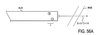
神経が装置もしくは装置の一部に対して、または組織を通る経路に沿ってどの方向に位置しているかを判定する装置、システムおよび方法を本書に記載する。本書に記載する神経刺激ツールはフレキシブルで薄型に構成されており、これにより圧迫されもしくは部分的に閉塞した神経孔内などの屈折しもしくは到達が困難な身体領域内でそれらを用いることができる。殆どの場合、本書に記載するこれらのツールは、例えば、別個の位置から、通常身体の外から装置の両端に力を加えることによって両手で操作するよう適合されている。したがって、本書に記載する多くの例示的な装置(ツール)では、ツールの遠位端領域がガイドワイヤの近位端に連結するよう構成されており、このような装置を用いる方法は遠位端および/または近位端の何れかまたは双方から引っ張るおよび/または押し進めることによって所定の位置に装置を引っ張るステップを含むことができる。 Described herein are devices, systems, and methods for determining in which direction a nerve is located relative to a device or part of a device or along a path through tissue. The nerve stimulation tools described herein are configured to be flexible and thin so that they can be used in body regions that are refracted or difficult to reach, such as in a nerve hole that is compressed or partially occluded. In most cases, these tools described herein are adapted to be operated with both hands, for example by applying force to the ends of the device from outside the body, usually from a separate location. Thus, in many exemplary devices (tools) described herein, the distal end region of the tool is configured to couple to the proximal end of the guidewire, and methods using such devices are And / or pulling the device into place by pulling and / or pushing from either or both proximal ends.
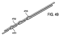
本書に記載する装置およびツールは、一般に「神経位置判定リボン」(または「NLR」)ツールもしくは装置、あるいは「神経位置判定」装置、または「神経系位置判定」装置ということができる。一般に、これらの装置は1以上の電極を支持するフレキシブルな本体を有する。電極は、近くの神経(例えば装置の一部から所定の距離内にある神経)を制御可能に刺激することができる電磁場を放出するよう構成することができる。電極は、露出した電極面のサイズと、NLR装置の端部から電極までの距離および/または電極間の間隔(双極もしくは他の多極構成の電極間の間隔を含む)との1以上に基づいてNLR装置の近くの神経のみを刺激するよう構成することができる。使用する電力(例えば電流もしくは電圧)は、放出場を制御するよう調節もしくは制限することができる。 The devices and tools described herein can generally be referred to as “neural location ribbon” (or “NLR”) tools or devices, or “neural location” devices, or “neural location” devices. Generally, these devices have a flexible body that supports one or more electrodes. The electrodes can be configured to emit an electromagnetic field that can controllably stimulate nearby nerves (eg, nerves within a predetermined distance from a portion of the device). The electrodes are based on one or more of the size of the exposed electrode surface and the distance from the end of the NLR device to the electrodes and / or the spacing between electrodes (including spacing between electrodes in bipolar or other multipolar configurations). And can be configured to stimulate only nerves near the NLR device. The power used (eg current or voltage) can be adjusted or limited to control the emission field.
言及したように、フレキシブルな本体はフレキシブルなリボン型本体とすることができる。例えば、本体は細長く、非常に薄く、厚さより大きい幅と、幅より大きい長さを有することができる。装置は、他の方向より幾つかの方向に曲がり易くすることができる。例えば、装置は幅に平行な方向ではなく、幅に垂直な方向に非常にフレキシブルにすることができる。 As mentioned, the flexible body can be a flexible ribbon type body. For example, the body can be elongated and very thin, having a width greater than thickness and a length greater than width. The device can be easier to bend in some directions than in other directions. For example, the device can be very flexible in a direction perpendicular to the width rather than in a direction parallel to the width.
本書に記載するNLR装置は独立型のツールとすることができ、および/またはそれらは組織改善ツールを具える1以上の他のツールに連結するよう構成することができる。幾つかの変形例では、NLR装置は組織改善ツールと一体化することができる。例えば、装置は組織改善領域の遠位にNLR領域を具えることができる。 The NLR devices described herein can be stand-alone tools and / or they can be configured to couple to one or more other tools, including tissue improvement tools. In some variations, the NLR device can be integrated with a tissue improvement tool. For example, the device can include an NLR region distal to the tissue improvement region.
一般に、これらの装置はNLR装置の1以上の面に沿って配置された多極電極を具えることができる。例えば、装置は直列の双極電極(陽極と陰極を交互にするなど)を具え、双極回路の一変形例を形成することができる。他の多極構成(例えば三極、四極等)を使用してもよい。このように、刺激電極は単極、双極、三極、四極、または他の構成で配列することができる。特に、少なくとも部分的に装置の面を横切ってもしくはその面に沿って延在するラインまたはパターンで1セットの電極を配置することができる。電極のセットは、電気的に連結された複数の電極を具えることができる(例えば、同じ陽極もしくは陰極源に接続される)。したがって、電極または電極のセットは、制御された(一般に小さな)距離でフレキシブルな本体から広がる放出場を生成することができ、装置に神経の近接度を確実に判定させることができる。本書に記載するNLR装置は複数のセットの電極を具え、神経刺激を適用することもできる。例えば、幾つかの変形例では、第1の刺激電極または第1のセットの電極が装置の第1の面(例えば頂面)に具えられ、第2のセットの別個に制御可能な電極が装置の第2の面(例えば底面)に具えられる。 In general, these devices can include multipolar electrodes disposed along one or more faces of the NLR device. For example, the device can comprise a series of bipolar electrodes (such as alternating anodes and cathodes) to form a variation of the bipolar circuit. Other multipolar configurations (eg, tripolar, quadrupole, etc.) may be used. Thus, the stimulation electrodes can be arranged in monopolar, bipolar, tripolar, quadrupolar, or other configurations. In particular, a set of electrodes can be arranged in a line or pattern that extends at least partially across or along the surface of the device. The set of electrodes can comprise a plurality of electrically coupled electrodes (eg, connected to the same anode or cathode source). Thus, the electrode or set of electrodes can generate an emission field that extends from the flexible body at a controlled (typically small) distance, allowing the device to reliably determine the proximity of the nerve. The NLR device described herein includes multiple sets of electrodes and can also apply neural stimulation. For example, in some variations, a first stimulation electrode or first set of electrodes is provided on a first surface (eg, top surface) of the device, and a second set of separately controllable electrodes is provided on the device. Of the second surface (for example, the bottom surface).
言及したように、本書に記載する装置は、組織改善装置と独立して使用することができる独立型のNLR装置として構成することができる。このようなNLR装置は、一般に第1の面(例えば頂面)および第2の面(例えば底面)を有するフレキシブルな本体領域と、ガイドワイヤに取り外し可能に連結するよう構成された遠位端領域と、ハンドルを含むか、もしくはこれと連結するよう構成された近位端領域とを具える。電極または電極のセットは、神経位置判定リボン装置の少なくとも一方の面に配置することができる。 As mentioned, the device described herein can be configured as a stand-alone NLR device that can be used independently of the tissue improvement device. Such an NLR device generally includes a flexible body region having a first surface (eg, a top surface) and a second surface (eg, a bottom surface) and a distal end region configured to removably connect to a guide wire. And a proximal end region configured to include or be coupled to the handle. The electrode or set of electrodes can be placed on at least one side of the nerve localization ribbon device.
本書に記載する神経位置判定装置は、一般に脊椎の神経孔を通るような屈折して狭い身体部位で用いるよう適合されている。例えば、本書に記載する装置は十分にフレキシブルであり、これにより狭く曲がっている身体部位を通してそれらを引き込み(例えば、引っ張り)、神経が近くかどうかを判定することができる。したがって、本書に記載する装置は、組織改善装置を配置し、操作する両手操作型のシステムと共に用いるよう適合することができる。両手を使う装置は、逆方向から装置の両端領域を引っ張ることによって標的組織に対して引っ張る、もしくは引き込むことができる。例えば、両手操作型装置は、最初に患者の外部から標的組織の周りにガイドワイヤを通し、患者の外部に戻すことによって、患者内に配置することができる。次いで、ガイドワイヤを用いて、本書に記載するフレキシブルな組織位置判定装置、もしくは組織改善装置、または双方などの装置を標的部位に近い位置に引っ張ることができる。例えば、組織改善装置および/または神経位置判定装置の遠位端領域をガイドワイヤに連結し、患者からガイドワイヤを(遠位に)引っ張って装置を配置することができる。ガイドワイヤを用いて他の装置、特に組織に対して往復運動させる組織改善装置を操作もしくは動かしてもよい。 The nerve location determination device described herein is generally adapted for use with a refracted and narrow body part that passes through a spinal nerve hole. For example, the devices described herein are sufficiently flexible so that they can be retracted (eg, pulled) through a narrowly bent body part to determine whether the nerve is near. Thus, the devices described herein can be adapted for use with a two-handed system for positioning and operating a tissue improvement device. A device using both hands can be pulled or retracted with respect to the target tissue by pulling the opposite end regions of the device from the opposite direction. For example, a two-handed device can be placed in a patient by first passing a guide wire around the target tissue from outside the patient and back to the outside of the patient. The guidewire can then be used to pull a device such as the flexible tissue position determination device or tissue improvement device described herein or both closer to the target site. For example, the distal end region of the tissue improvement device and / or nerve localization device can be coupled to a guidewire and the device can be placed by pulling the guidewire (distal) from the patient. A guide wire may be used to manipulate or move other devices, particularly tissue improvement devices that reciprocate relative to tissue.
幾つかの変形例では、本書に記載するNLR装置は、組織改善装置を含む1以上の他の装置と組み合わせて用いるよう構成されている。例えば、NLR装置は組織改善装置の端部、例えば遠位端と連結するよう適合することができる。組織改善装置の実施例は、先に援用した特許出願の多く、例えば米国特許出願第12/324,147号で見つけることができる。NLR装置は、組織改善装置と連結する別個の装置としてもよいし、それは組織改善装置の一体化した部分でもよい。例えば、組織改善装置はフレキシブルなNLR領域を含む遠位領域を具えることができる。 In some variations, the NLR devices described herein are configured for use in combination with one or more other devices, including tissue improvement devices. For example, the NLR device can be adapted to couple with the end of the tissue improvement device, eg, the distal end. Examples of tissue improvement devices can be found in many of the previously incorporated patent applications, eg, US patent application Ser. No. 12 / 324,147. The NLR device may be a separate device that interfaces with the tissue improvement device, or it may be an integral part of the tissue improvement device. For example, the tissue modification device can comprise a distal region that includes a flexible NLR region.
NLR装置は任意の適切な手法で組織改善装置と連結することができる。例えば、フレキシブルな神経位置判定装置は組織改善装置の遠位端に連結することによって組織改善装置に連結することができる。連結部は、組織改善装置のガイドワイヤ取り付け領域などの取り付け部品とすることができる。このように、組織改善装置の遠位端の同じカプラを用いてガイドワイヤやNLR装置(またはNLR装置に連結するアダプタ)に連結することができる。幾つかの変形例では、フレキシブルな神経位置判定装置が組織改善装置の少なくとも一部が適合するスリーブとして構成される。NLR装置は、引き剥がせるカバーもしくはスリーブとすることができる。例えば、引き剥がせるスリーブは組織改善装置の全部もしくは一部を覆うことができるが、それを遠位へ引っ張るか、またはNLR装置のスリットもしくは脆弱な領域を介してそれを取り外すことによって取り外すことができる。幾つかの変形例では、NLR装置は組織改善装置が適合することができるトラックまたはチャネルを具える。 The NLR device can be coupled to the tissue improvement device in any suitable manner. For example, a flexible nerve location determination device can be coupled to the tissue improvement device by coupling to the distal end of the tissue improvement device. The connecting portion can be an attachment component such as a guide wire attachment region of the tissue improvement device. In this way, the same coupler at the distal end of the tissue improvement device can be used to connect to a guidewire or NLR device (or an adapter that connects to the NLR device). In some variations, the flexible nerve location determination device is configured as a sleeve to which at least a portion of the tissue improvement device is fitted. The NLR device can be a peelable cover or sleeve. For example, the peelable sleeve can cover all or part of the tissue improvement device, but can be removed by pulling it distally or by removing it through a slit or fragile region of the NLR device it can. In some variations, the NLR device includes a track or channel to which the tissue improvement device can be fitted.
本書に記載するフレキシブルなNLR装置は、身体部位を拡張させるか、または測定するよう適合することもできる。例えば、フレキシブルなNLR装置は身体部位を膨脹させるよう適合することができる。フレキシブルな神経位置判定装置は、くさび型のおよび/または拡張可能な領域を具えることができる。本書に記載するフレキシブルな神経位置判定装置は、ドラッグデリバリを提供するよう適合することもできる(例えば、ドラッグデリバリ用の1以上のチャネルを具える)。幾つかの変形例では、記載するフレキシブルな神経位置判定装置は追加電極を具えてもよいし、またはそれら自身の電極が組織を凝固もしくは切除する高周波(RF)エネルギを適用するよう適合してもよい。 The flexible NLR devices described herein can also be adapted to expand or measure body parts. For example, a flexible NLR device can be adapted to inflate a body part. The flexible nerve location device can comprise a wedge-shaped and / or expandable region. The flexible nerve location device described herein can also be adapted to provide drug delivery (eg, comprising one or more channels for drug delivery). In some variations, the described flexible neural localization device may include additional electrodes, or their own electrodes may be adapted to apply radio frequency (RF) energy to coagulate or ablate tissue. Good.
これらの変形例の殆どの実施例は、以下で図示されている。図示する実施例の態様は、省略するか、重複するか、フレキシブルな神経位置判定装置の他の特徴と組み合わせることができ、依然として本書に記載する装置、システムおよび方法の範囲内にあると理解されたい。 Most embodiments of these variations are illustrated below. It is understood that aspects of the illustrated embodiment can be omitted, overlapped, or combined with other features of a flexible neural localization device and still be within the scope of the devices, systems and methods described herein. I want.
例えば、神経が装置の領域の近くにあるかどうかを判定することが可能な両手操作型の神経位置判定装置において、第1の面と第2の面を有するリボン型のフレキシブルな細長い本体であって、第1の面と第2の面が実質的に平行である細長い本体と、第1の面の長手方向の少なくとも一部に沿って制限された神経の刺激場を放出するよう構成された刺激領域を含む第1の面の刺激領域と、細長い本体の遠位端領域にガイドワイヤカプラとを具える装置を本書に記載する。 For example, in a two-hand operation type nerve position determination device capable of determining whether or not a nerve is close to a region of the device, a ribbon-type flexible elongated body having a first surface and a second surface. And an elongated body having a first surface and a second surface substantially parallel, and a limited nerve stimulation field along at least a portion of the length of the first surface. Described herein is a device comprising a first surface stimulation region including a stimulation region and a guidewire coupler at a distal end region of the elongated body.
別の実施例では、神経が装置の領域の近くにあるかどうかを判定することが可能なフレキシブルな神経位置判定装置が、軸方向の長さと、幅と、厚さとを有するフレキシブルな細長い本体であって、軸方向の長さが幅より長く、当該幅が厚さより大きいフレキシブルな細長い本体と、双極回路を含む細長い本体の刺激領域であって、双極回路が双極の刺激場を形成するよう構成された陽極および陰極を含む刺激領域と、細長い本体の遠位端領域にガイドワイヤカプラとを具える。 In another embodiment, a flexible nerve location device capable of determining whether a nerve is near the area of the device is a flexible elongated body having an axial length, width and thickness. A stimulating region of a flexible elongated body including an axial length longer than a width and a width greater than a thickness and a bipolar circuit, wherein the bipolar circuit forms a bipolar stimulation field A stimulating region including a shaped anode and cathode, and a guidewire coupler at the distal end region of the elongated body.
さらに別の実施例では、神経が装置の1以上の領域の近くにあるかどうかを判定することが可能なフレキシブルな神経位置判定装置が、第1の面と第2の面を有するフレキシブルな細長い本体であって、第1の面と第2の面が実質的に平行である細長い本体と、第1の面に沿って配置され、第1の面の少なくとも一部に沿って効率的に連続する双極場を放出するよう構成された第1の双極回路と、第2の面に沿って配置され、第2の面の少なくとも一部に沿って効率的に連続する双極場を放出するよう構成された第2の双極回路と、細長い本体の遠位端領域にガイドワイヤカプラとを具える。 In yet another embodiment, a flexible nerve localization device capable of determining whether a nerve is near one or more regions of the device is a flexible elongated having a first surface and a second surface. A body, wherein the first surface and the second surface are substantially parallel, and the body is disposed along the first surface and is efficiently continuous along at least a portion of the first surface. A first bipolar circuit configured to emit a dipole field that is configured to emit a dipole field disposed along the second surface and efficiently continuous along at least a portion of the second surface. A second bipolar circuit configured and a guidewire coupler in the distal end region of the elongated body.
これらの変形例の何れかでは、双極電極対を細長い本体の遠位端に配置することができる。細長い本体は、リボン型とすることができる。幾つかの変形例では、細長い本体の幅が細長い本体の長手方向に沿って変化する。例えば、細長い本体の遠位部分の幅を細長い本体の近位部分の幅より小さくすることができる。細長い本体の厚さは、細長い本体の長手方向に沿って変化する。例えば、細長い本体の遠位部分の厚さを細長い本体の近位部分の厚さより薄くすることができる。この装置は、細長い本体の長手方向に沿って分布する放射線不透過性マーカを具える。 In any of these variations, a bipolar electrode pair can be placed at the distal end of the elongated body. The elongate body can be ribbon-shaped. In some variations, the width of the elongated body varies along the length of the elongated body. For example, the width of the distal portion of the elongate body can be less than the width of the proximal portion of the elongate body. The thickness of the elongated body varies along the longitudinal direction of the elongated body. For example, the thickness of the distal portion of the elongated body can be less than the thickness of the proximal portion of the elongated body. The device includes radiopaque markers distributed along the length of the elongated body.
本書に記載するNLR装置の何れかは、装置の近位端領域にハンドルまたはハンドル取り付け領域を具えることもできる。本書に記載するNLR装置の幾つかの変形例は、長手方向の少なくとも一部に沿って拡張可能なバルーン、および/または細長い本体の長手方向に沿って配置したチャネルを具えることができる。例えば、装置は薬剤リザーバ、洗浄流体リザーバ、および/または吸引器と流体連通するチャネルを具えることができる。 Any of the NLR devices described herein can also include a handle or handle attachment region at the proximal end region of the device. Some variations of the NLR devices described herein may include a balloon that is expandable along at least a portion of the longitudinal direction, and / or a channel disposed along the length of the elongated body. For example, the device can include a channel in fluid communication with a drug reservoir, a irrigation fluid reservoir, and / or an aspirator.
NLR装置の刺激領域は、NLR装置の1以上の面に配置することができる。例えば、NLR装置はフレキシブルな細長い本体の第1の面であって、刺激領域が配置される第1の面を具えることができる。 The stimulation region of the NLR device can be placed on one or more surfaces of the NLR device. For example, the NLR device can include a first surface of a flexible elongate body on which a stimulation region is disposed.
NLR装置の電極(例えば、双極回路)は、複数の陽極および複数の陰極であって、フレキシブルな細長い本体の一部に沿って効率的に連続する双極場を形成するよう構成された複数の陽極および複数の陰極を具えることができる。複数の陽極は、第1の陽極の導体と電気通信することができる。複数の陰極は、第1の陰極の導体と電気通信することができる。 An electrode of an NLR device (eg, a bipolar circuit) includes a plurality of anodes and a plurality of cathodes configured to form an efficient continuous bipolar field along a portion of a flexible elongated body. And may comprise a plurality of cathodes. The plurality of anodes can be in electrical communication with the conductors of the first anode. The plurality of cathodes can be in electrical communication with a conductor of the first cathode.
幾つかの変形例では、陽極が1列に配置され、および/または陰極が1列に配置される。陽極および陰極の他の配置を用いてもよい。一般に、双極回路を形成する陰極および陽極はNLR装置の長手方向の一部に沿って延在することができる。 In some variations, the anodes are arranged in a row and / or the cathodes are arranged in a row. Other arrangements of the anode and cathode may be used. In general, the cathode and anode forming the bipolar circuit can extend along a portion of the length of the NLR device.
また、神経が装置の領域の近くにあるかどうかを判定する方法であって、少なくとも部分的に標的組織周りにリボン型の神経位置判定装置を通すステップであって、リボン型の神経位置判定装置が実質的に平行な第1の面および第2の面を有するリボン型のフレキシブルな細長い本体と、刺激電極を有する第1の面に刺激領域とを具えるステップと、第1の面の長手方向の少なくとも一部に沿って制限された神経の刺激場を放出するよう刺激電極を起動するステップと、神経が放出場によって刺激されたかどうかを判定するステップとを含む方法を本書に記載する。 A method for determining whether a nerve is near a region of a device, the step of passing a ribbon-type nerve position determination device at least partially around a target tissue, the ribbon-type nerve position determination device Comprising a ribbon-shaped flexible elongate body having first and second surfaces substantially parallel to each other, a stimulation region on the first surface having the stimulation electrode, and a length of the first surface. Described herein is a method comprising activating a stimulation electrode to emit a limited nerve stimulation field along at least a portion of a direction and determining whether the nerve has been stimulated by the emission field.
少なくとも部分的に標的組織周りにリボン型の神経位置判定装置を通すステップは、少なくとも部分的に標的組織周りにガイドワイヤを通し、ガイドワイヤを用いて標的組織周りに装置を引っ張るステップを含むことができる。リボン型の神経位置判定装置を通すステップは、神経位置判定装置の近位端と遠位端の双方に張力を加えるステップを含むことができる。 Passing the ribbon-type nerve localization device at least partially around the target tissue includes passing a guidewire around the target tissue at least partially and using the guidewire to pull the device around the target tissue. it can. Passing the ribbon-type nerve location device may include applying tension to both the proximal and distal ends of the nerve location device.
NLR装置(またはNLR装置を具えるシステム)に関する方法の何れかに関して、標的組織は任意の適切な組織とすることができ、改善もしくは除去すべき組織を含む。例えば、標的組織は椎孔内の組織を含むことができる。標的組織は、限定されないが、脊柱靭帯(黄色靭帯など)および/または骨組織(上関節突起、下関節突起、椎弓根、葉節、または任意の他の適切な脊椎の骨組織など)を含むことができる。非標的組織は、神経(神経性の)組織を含むことができる。 For any of the methods relating to an NLR device (or a system comprising an NLR device), the target tissue can be any suitable tissue, including the tissue to be improved or removed. For example, the target tissue can include tissue within the foramina. Target tissues include, but are not limited to, spinal ligaments (such as yellow ligaments) and / or bone tissues (such as superior articular processes, inferior articular processes, pedicles, lobes, or any other suitable spinal bone tissue). Can be included. Non-target tissue can include neural (neural) tissue.
また、組織を改善する方法であって、少なくとも部分的に標的組織周りにリボン型の神経位置判定装置を通すステップであって、リボン型の神経位置判定装置が実質的に平行である第1の面および第2の面を有するリボン型のフレキシブルな細長い本体と、刺激電極を有する第1の面に刺激領域とを具えるステップと、第1の面の長手方向の少なくとも一部に沿って制限された神経の刺激場を放出するよう刺激電極を起動するステップと、神経がリボン型の神経位置判定装置の第1の面に隣接していないことを判定するステップと、神経位置判定装置と同じ組織を通る経路に沿って少なくとも部分的に標的組織周りにフレキシブルな組織改善装置を通すステップであって、フレキシブルな組織改善装置が組織改善領域を有するフレキシブルな細長い本体を具え、当該組織改善領域がリボン型の神経位置判定装置の第1の面と同じ向きに配向された少なくとも1つの切除端を具えるステップと、装置の少なくとも一端から組織改善装置を引っ張ることによって標的組織に対して組織改善装置を推進するステップと、切除端で標的組織を切除するステップとを含む方法を本書に記載する。 A method of improving tissue, the method comprising: passing a ribbon-type nerve localization device at least partially around a target tissue, wherein the ribbon-type nerve localization device is substantially parallel. A ribbon-shaped flexible elongate body having a surface and a second surface; a step of providing a stimulation region on the first surface having a stimulation electrode; and limiting along at least a portion of the length of the first surface Activating the stimulation electrode to emit the stimulated nerve stimulation field, determining that the nerve is not adjacent to the first surface of the ribbon type nerve position determination device, and the same as the nerve position determination device Passing a flexible tissue improvement device at least partially around a target tissue along a path through the tissue, the flexible tissue improvement device having a tissue improvement region Pulling the tissue improvement device from at least one end of the device comprising a long body, the tissue improvement region having at least one resection end oriented in the same orientation as the first surface of the ribbon-type nerve localization device; A method is described herein that includes pushing a tissue improvement device relative to a target tissue and ablating the target tissue at the resection end.
少なくとも部分的に標的組織周りにリボン型の神経位置判定装置を通すステップは、標的組織周りにガイドワイヤを通すステップと、ガイドワイヤを用いて標的組織周りに神経位置判定装置を引っ張るステップとを含む。 Passing the ribbon-type nerve localization device at least partially around the target tissue includes passing a guide wire around the target tissue and pulling the nerve localization device around the target tissue using the guide wire. .
本書に記載する方法の何れかは、神経位置判定装置の近位端を引っ張り、ガイドワイヤからリボン型の神経位置判定装置を切り離すことによって、リボン型の神経位置判定装置を取り外すステップを含むこともできる。同様に、この方法はガイドワイヤにフレキシブルな組織改善装置を連結するステップを含むことができる。 Any of the methods described herein may include removing the ribbon-type nerve locator by pulling the proximal end of the nerve locator and detaching the ribbon-type nerve locator from the guide wire. it can. Similarly, the method can include coupling a flexible tissue improvement device to the guidewire.
フレキシブルな組織改善装置を通すステップは、第2のガイドワイヤを用いて標的組織周りにフレキシブルな組織改善装置を引っ張るステップであって、リボン型の神経位置判定装置がフレキシブルな組織改善装置より前方にあるステップを含むこともできる。 The step of passing the flexible tissue improvement device is a step of pulling the flexible tissue improvement device around the target tissue using the second guide wire, wherein the ribbon-type nerve localization device is in front of the flexible tissue improvement device. A step can also be included.
フレキシブルな組織改善装置は、標的組織周りにガイドワイヤを通し、ガイドワイヤを用いて標的組織周りにフレキシブルな組織改善装置を引っ張ることによって、少なくとも部分的に標的組織周りに通すことができる。このように、ガイドワイヤの近位端は固定する手法で神経位置判定装置の遠位端に連結することができる。組織改善装置は、組織改善装置の近位端領域と遠位端領域の双方に張力を加えることによって、標的組織に対して推進することができる。張力は、ガイドワイヤの遠位端と神経位置判定装置の近位端を引っ張ることによって加えることができる。 The flexible tissue improvement device can be at least partially threaded around the target tissue by passing the guidewire around the target tissue and using the guidewire to pull the flexible tissue improvement device around the target tissue. In this way, the proximal end of the guide wire can be coupled to the distal end of the nerve localization device in a fixed manner. The tissue improvement device can be driven against the target tissue by applying tension to both the proximal and distal end regions of the tissue improvement device. Tension can be applied by pulling the distal end of the guidewire and the proximal end of the nerve location device.
さらに、神経が装置の1以上の領域の近くにあるかどうかを判定することが可能なシステムであって、神経位置判定装置と、エネルギを適用して第1の双極回路の双極場を放出するよう構成された制御部と、神経位置判定(NLR)装置のガイドワイヤカプラに連結するよう構成されたガイドワイヤとを具えるシステムを本書に記載する。神経位置判定装置は、第1の領域と第2の領域の外面を有するフレキシブルな細長い本体と、細長い本体の遠位端領域のガイドワイヤカプラと、複数の陽極と複数の陰極を具える第1の双極回路であって、複数の陽極と複数の陰極が第1の領域の外面に沿って効率的に連続する双極場を放出するよう構成されている第1の双極回路とを具える。 Further, a system capable of determining whether a nerve is near one or more regions of the device, wherein the nerve location device and energy are applied to emit a bipolar field of the first bipolar circuit. A system comprising a controller configured as described above and a guidewire configured to couple to a guidewire coupler of a nerve location determination (NLR) device is described herein. A nerve localization apparatus includes a flexible elongate body having outer surfaces of a first region and a second region, a guide wire coupler at a distal end region of the elongate body, a plurality of anodes and a plurality of cathodes. A plurality of anodes and a plurality of cathodes configured to emit a continuous bipolar field efficiently along the outer surface of the first region.
システムは、制御部に接続された電源を具えることもできる。幾つかの変形例では、NLR装置が遠位端から電力を供給されるよう構成されており、他の変形例では、NDR装置がNLR装置の遠位端に作られた電極に接続することによって電力を提供するよう構成されている。例えば、NLR装置が遠位端に電極に接続する取り付け領域を具えることができる。 The system can also include a power source connected to the controller. In some variations, the NLR device is configured to be powered from the distal end, and in other variations, the NDR device is connected to an electrode made at the distal end of the NLR device. It is configured to provide power. For example, the NLR device can include an attachment region that connects to the electrode at the distal end.
幾つかの変形例では、システムが神経の刺激を検出するセンサを具えることができる。センサは、動作(例えば、筋収縮、総計の筋運動等)、EMGなどを検出することができる。 In some variations, the system may include a sensor that detects neural stimulation. The sensor can detect movement (eg, muscle contraction, total muscle movement, etc.), EMG, and the like.
システムは、NLR装置の近位端にハンドルまたはハンドル取り付け領域を具えることもできる。 The system can also include a handle or handle attachment region at the proximal end of the NLR device.
幾つかの変形例では、システムが神経位置判定装置の外面の第1の領域の近くに組織改善領域を具える。幾つかの変形例では、システムが組織改善装置を具える。NLR装置は組織改善装置に連結するよう構成することができ、もしくは2つは別個に動作するよう構成することができる。 In some variations, the system includes a tissue improvement region near a first region on the outer surface of the nerve location device. In some variations, the system includes a tissue improvement device. The NLR device can be configured to couple to the tissue improvement device, or the two can be configured to operate separately.
さらに、神経が装置の領域の近くにあるかどうかを判定することが可能な神経位置判定装置を本書に記載する。これらの装置は、第1の面と第2の面を有するフレキシブルな細長い本体であって、第1の面と第2の面が実質的に平行である細長い本体と、第1の面の長手方向の少なくとも一部に沿って制限された神経の刺激場を放出するよう構成された双極対を含む第1の面の刺激領域と、組織改善装置の遠位端に連結するよう構成された装置の近位端領域の近位カプラと、細長い本体の遠位端領域のガイドワイヤカプラとを具える。近位カプラは、組織改善装置の遠位端の少なくとも一部が適合することができる空胴を具えることができる。例えば、近位カプラは装置の近位端を曲げることによって解放されるよう構成することができる。 Further described herein is a nerve location determination device capable of determining whether a nerve is near the area of the device. The devices include a flexible elongated body having a first surface and a second surface, the elongated body having the first surface and the second surface substantially parallel, and the length of the first surface. A first surface stimulation region including a bipolar pair configured to emit a limited nerve stimulation field along at least a portion of a direction, and a device configured to couple to a distal end of a tissue improvement device A proximal coupler in the proximal end region of the body and a guide wire coupler in the distal end region of the elongated body. The proximal coupler can include a cavity in which at least a portion of the distal end of the tissue improvement device can fit. For example, the proximal coupler can be configured to be released by bending the proximal end of the device.
また、脊椎の組織を改善する方法であって、患者の外部から、患者内の標的組織周りに、かつ患者の外へガイドワイヤの遠位端を導くステップであって、これによりガイドワイヤの近位端と遠位端が患者から延在するステップと、ガイドワイヤの近位端にフレキシブルな神経位置判定装置の遠位端を連結するステップと、ガイドワイヤを用いて標的組織周りにフレキシブルな神経位置判定装置を配置するステップと、神経がフレキシブルな神経位置判定装置と標的組織との間に存在するかどうかを判定するステップと、ガイドワイヤを用いて標的組織周りに組織改善装置を配置するステップと、標的組織に対して組織改善装置を推進し、組織改善装置を用いて標的組織を改善するステップとを含む方法を本書に記載する。 There is also a method for improving spinal tissue, the step of guiding the distal end of a guidewire from outside the patient, around the target tissue in the patient, and out of the patient, whereby the guidewire is proximate. A distal end and a distal end extending from the patient; connecting a distal end of a flexible nerve locator to the proximal end of the guidewire; and a flexible nerve around the target tissue using the guidewire Placing a position determining device; determining whether a nerve is present between the flexible nerve position determining device and the target tissue; and positioning a tissue improvement device around the target tissue using a guide wire And a method of promoting a tissue improvement device relative to a target tissue and using the tissue improvement device to improve the target tissue is described herein.
一般に、ガイドワイヤを用いてフレキシブルな神経位置判定装置を配置するステップが、フレキシブルな神経位置判定装置の遠位端を引っ張るステップを含むことができる。組織改善装置は、フレキシブルな神経位置判定装置に組織改善装置を連結し、引っ張ることによって配置することができる。 In general, deploying the flexible nerve location device using the guidewire can include pulling the distal end of the flexible nerve location device. The tissue improvement device can be arranged by connecting and pulling the tissue improvement device to a flexible nerve position determination device.
本書に記載するNLR装置の何れかを用いる方法は、神経位置判定装置を用いて標的組織周りに領域を膨脹させるステップを含むこともできる。 Methods using any of the NLR devices described herein can also include expanding a region around the target tissue using a nerve location determination device.
本書に記載する変形例の何れかでは、電極が神経系位置判定/神経位置判定装置の面から突出することができる。例えば、電極は神経位置判定リボン装置の頂面および/または底面の相対的に平らな面から延在することができる。この構成では、電極は装置の面(頂面および/または底面)に対して突出するというか、または単に「突出した電極」ということができる。突出した電極は、任意の適切な導電材料で形成することができる。例えば、突出した電極はリボン型の装置の本体から延在する導電性の金属で形成することができる。全てまたは電極のサブセットを突出させることができる。突出した電極は、0.01mm以上まで、0.1mmまで、1mmまで、1.5mmまで、2mmまで等、装置の面から延在する。本書に記載する突出した電極は、同一平面上の電極または凹んだ電極を有する構成と比べて神経位置判定装置に対してより高い感度を提供することができる。 In any of the variations described herein, the electrodes can protrude from the face of the nervous system location determination / neural location determination device. For example, the electrodes can extend from a relatively flat surface at the top and / or bottom of the nerve localization ribbon device. In this configuration, the electrodes can protrude relative to the face (top and / or bottom) of the device, or simply “protruded electrodes”. The protruding electrode can be formed of any suitable conductive material. For example, the protruding electrode can be formed of a conductive metal that extends from the body of the ribbon-type device. All or a subset of the electrodes can be projected. The protruding electrodes extend from the surface of the device, such as up to 0.01 mm or more, up to 0.1 mm, up to 1 mm, up to 1.5 mm, up to 2 mm, etc. The protruding electrodes described herein can provide higher sensitivity to the nerve location determination device compared to configurations with coplanar or recessed electrodes.
本書に記載する神経系位置判定/神経位置判定装置は、実質的に平らな断面を有するフレキシブルな細長いリボン型の本体を具えることができる。一般に、リボン型の本体は本体の長手方向に沿って上方もしくは下方へ(例えば、リボンの面より上および下)曲がるよう構成することができる。リボン型の本体は、それが例えば、リボン型の平面(リボン型の本体の薄い面に沿って)−側面に対して実質的に屈曲しないよう構成することができる。 The nervous system location / neural location device described herein can include a flexible elongated ribbon-type body having a substantially flat cross-section. In general, a ribbon-type body can be configured to bend up or down (eg, above and below the ribbon face) along the length of the body. The ribbon-type body can be configured so that it does not substantially bend, for example, relative to the side of the ribbon-type plane (along the thin surface of the ribbon-type body).
幾つかの変形例では、本書に記載する神経位置判定装置がH形(またはI形)の断面構成を有する。この変形例では、外面(「頂」および「底」面)は内面の電極と双極電極対を形成することができる。これは、リボン型の装置の「頂面」電極によって放出される電流を制限して、装置の底面の刺激を防止することができ、底部の内面の電極と対になる底部の外面の電極についても同様である。 In some variations, the nerve location determination device described herein has an H-shaped (or I-shaped) cross-sectional configuration. In this variation, the outer surface (the “top” and “bottom” surfaces) can form a bipolar electrode pair with the inner electrode. This can limit the current emitted by the “top” electrode of the ribbon-type device and prevent irritation of the bottom surface of the device, with the bottom outer electrode paired with the bottom inner electrode. Is the same.
本書に記載する変形例の何れかは、双極または単極の構成で用いることができる。単極もしくは双極の構成の何れかでは、電極の極性(例えば、陽極/陰極またはエミッタ/グランド)を逆にすることができる。幾つかの状況では、神経が陽極の刺激ではなく陰極に感受性があってもよく、またはその逆でもよい。したがって、陰極もしくは陽極の何れかと同じセットの電極を刺激するよう極性を逆にすることは価値がある。 Any of the variations described herein can be used in a bipolar or unipolar configuration. In either monopolar or bipolar configurations, the polarity of the electrodes (eg, anode / cathode or emitter / ground) can be reversed. In some situations, the nerve may be sensitive to the cathode rather than the anode, or vice versa. It is therefore worthwhile to reverse the polarity to stimulate the same set of electrodes as either the cathode or the anode.
本書に記載する装置の変形例の何れかは、同心円状に配置される電極を具えることができる。例えば、リボン型の装置は1以上の電極対を有する頂面と、1以上の電極対を有する底面とを有することができる。内部の(例えば、−)電極が外部の(+)電極によって囲まれる、または内部の(+)電極が外部の(−)電極によって囲まれるように電極対を配置することができる。同心円状に配置された電極は、同心円でない(例えば、隣接して配置された)双極電極対に比べて制限された広がりの電流を提供することができる。したがって、双極対の陽極で陰極を取り囲むことは、電流方向を制御するのに役立つであろう。 Any of the device variations described herein may include electrodes arranged concentrically. For example, a ribbon-type device can have a top surface with one or more electrode pairs and a bottom surface with one or more electrode pairs. The electrode pair can be arranged such that the internal (eg, −) electrode is surrounded by an external (+) electrode, or the internal (+) electrode is surrounded by an external (−) electrode. Electrodes arranged in concentric circles can provide a limited spread of current compared to bipolar electrode pairs that are not concentric (eg, arranged adjacent). Thus, surrounding the cathode with a bipolar pair of anodes will help control the current direction.
本書に記載する装置は1以上のマーカを具え、処置の実行中の視覚化と配向を支援することができる。例えば、本書に記載する装置は1以上の放射線不透過マーカを具え、X線透視法などの撮像技術を用いて視覚化を支援することができる。幾つかの変形例では、装置が神経刺激領域をひとまとめにする一組のマーカを具える。例えば、装置は、装置の神経刺激領域の何れかの面に一組の放射線不透過リング/コイルを具えることができる。これらの実施例の装置の神経刺激領域は、1または複数の電極が配置される領域とすることができる。マーカはプラチナイリジウムなどの高密な物質とすることができ、もしくはそれは高密な物質(例えば、孔)のないものとすることができる。例えば、幾つかの変形例では、マーカは装置の細長い本体を通る1以上の孔であり、これはX線透視下で装置の明るい領域として出現するであろう。 The device described herein can include one or more markers to assist in visualization and orientation during the procedure. For example, the devices described herein can include one or more radiopaque markers and assist in visualization using imaging techniques such as fluoroscopy. In some variations, the device includes a set of markers that group the nerve stimulation area. For example, the device can include a set of radiopaque rings / coils on either side of the nerve stimulation area of the device. The neurostimulation region of the devices of these examples can be a region where one or more electrodes are disposed. The marker can be a dense material such as platinum iridium or it can be free of dense material (eg, pores). For example, in some variations, the marker is one or more holes through the elongated body of the device, which will appear as a bright area of the device under fluoroscopy.
マーカを用いて装置の適切な配置に役立てることができ、これにより標的組織に対して要求通りに刺激領域を配置することができる。 A marker can be used to help with proper placement of the device, thereby placing the stimulation region on the target tissue as desired.
一般に、本書に記載する装置および方法は特に、脊椎の神経孔に対する脊髄減圧処置の一部として使用するに適している。本書に記載するリボン型の装置は、例えばリボン型装置の遠位端に連結されたガイドワイヤを用いて孔に引っ張ることによって、先に記載する椎孔内に配置することができる。装置の遠位端に連結されたガイドワイヤを用いて所定の位置に引っ張るとき、連結したガイドワイヤを用いて近位および遠位へ(例えば、ハンドルまたはリボン型の装置の遠位端を用いて)装置を操作することができる。幾つかの変形例では、装置の遠位端が患者から延在するよう構成され、これによりガイドワイヤを装置から切り離すことができる(またはこれにより別個のガイドワイヤなしにそれを用いることができる)。一旦所定の位置になると、遠位端を引っ張ることによって(例えば、第2の部位から患者を出るガイドワイヤを引っ張る)、および/または近位端から押し進めることによって(例えば、神経位置判定装置のハンドル領域を押す)、神経位置判定装置を操作することができる(例えば、身体内に配置する)。 In general, the devices and methods described herein are particularly suitable for use as part of spinal cord decompression procedures for spinal nerve holes. The ribbon-type device described herein can be placed in the previously described vertebral foramen, for example, by pulling into the hole using a guide wire coupled to the distal end of the ribbon-type device. When pulled in place using a guidewire connected to the distal end of the device, it is proximally and distally using the connected guidewire (eg, using the distal end of a handle or ribbon type device) ) Can operate the device. In some variations, the distal end of the device is configured to extend from the patient, so that the guidewire can be disconnected from the device (or it can be used without a separate guidewire). . Once in place, by pulling the distal end (eg, pulling a guidewire that exits the patient from the second site) and / or by pushing from the proximal end (eg, the handle of the nerve locator) Push the area), the nerve position determination device can be operated (eg placed in the body).
本書に記載する刺激は、リボン型の装置の第1の(例えば頂)面の電極の起動により近くの神経からより大きな反応を得ると、脊髄神経根などの神経がリボンのこちらの面にあることを示し、またはリボン型の装置の第2の(例えば、背)面の電極を起動するときに神経から大きな反応を得ると、神経が装置の他方の(背)面により近いことを示す。稀に、装置の正面と背面の刺激が神経反応を誘発しなかったり、または結論のない反応のみを誘発することがある。しかしながら、特に神経位置判定装置の位置が組織切断/組織改善装置の開始位置として用いられるとき、リボン型装置のどの面に神経があるかを明確に判定することは重要となるであろう。この場合、この方法が神経根の切除および患者に損傷をもたらさないことを開始位置に対する神経位置の確認が裏づけるであろう。このように、様々な別個の領域または神経位置判定装置の向き(例えば、正面/背面)からの刺激に対する反応を比較して、身体を通る経路(神経位置判定装置の経路)に対する神経(または複数の神経)の関係を判定する方法およびシステムを本書に記載する。経路は、一般に標的部位周りに延在する。幾つかの変形例では、この方法は、(除去される)標的組織と、組織を通り標的組織周りの経路との間に神経があるかどうかを判定する方法とみなすことができる。 The stimuli described in this document have nerves such as spinal nerve roots on this side of the ribbon when a greater response is obtained from nearby nerves by activation of the first (eg, apical) surface electrode of the ribbon-type device. Or a large response from the nerve when activating the electrode on the second (eg, dorsal) surface of the ribbon-type device indicates that the nerve is closer to the other (dorsal) surface of the device. In rare cases, stimuli on the front and back of the device may not elicit a neural response, or only an unrecognized response. However, it may be important to clearly determine which side of the ribbon type device is nerve, particularly when the position of the nerve location determination device is used as the starting position of the tissue cutting / tissue improvement device. In this case, confirmation of the nerve position relative to the starting position will support that this method does not cause nerve root resection and damage to the patient. In this way, the nerves (or multiples) for the path through the body (the path of the nerve locator) are compared by comparing responses to stimuli from various distinct areas or orientations of the nerve locator (eg, front / back). A method and system for determining the (nervous) relationship is described herein. The pathway generally extends around the target site. In some variations, this method can be viewed as a method of determining whether there is a nerve between the target tissue (to be removed) and the path through the tissue and around the target tissue.
動作では、一方または双方の端部に力を加えて、装置(および特に装置の1以上の電極)を「下に」(例えば、患者の正面または腹側/前柱の前方へ)押し進めることが有益であろう。端部を押し進めるか、または引っ張ることによってリボン型の神経位置判定装置の刺激領域を推進するステップは、本書に記載する方法の何れかの一部として用いることができるが、刺激して反応を誘発しても神経への効果が曖昧な(または効果が無い)場合に特に有用となるであろう。例えば、刺激するときに装置の遠位端および近位端領域の双方を押し進めるステップは、神経がリボン装置と標的組織との間にあるかどうか、または装置が標的組織からリボン型装置の対向面にあるかどうかを判定するのに役立つであろう。 In operation, a force may be applied to one or both ends to push the device (and in particular one or more electrodes of the device) “down” (eg, in front of the patient or forward of the ventral / frontal column). It will be beneficial. The step of driving the stimulation area of the ribbon-type nerve localization device by pushing or pulling the end can be used as part of any of the methods described herein, but stimulates to induce a response. However, it will be particularly useful when the effect on the nerve is vague (or ineffective). For example, pushing both the distal and proximal end regions of the device when stimulating may determine whether the nerve is between the ribbon device and the target tissue, or whether the device is from the target tissue to the opposing surface of the ribbon device. It will be helpful to determine if there is.
さらに、神経位置の判定を支援するために送達時に拡張するリボン型の神経位置判定装置を本書に記載する。例えば、幾つかの変形例では、神経位置判定装置が、少なくとも装置の刺激領域であって、リボン型の装置の第1および第2の細長い平面の間に膨張可能な要素(例えば、バルーン)を具えることができる。幾つかの変形例では、刺激領域の一方または双方の面がバルーンの外面に対応する。動作において、拡張可能な神経刺激領域を具える装置は、拡張していない構成で身体内(例えば、脊椎の神経孔内)に配置することができる。一旦要求通りに配置されると、神経の機械的な刺激が達成される(すなわち、例えば、EMGで測定される)まで、装置を拡張することができる(例えば、膨張する)。次いで、刺激がなくなるまで拡張/膨張を戻すか、減少することができる。その後、本書に記載するように装置を刺激することができる。例えば、頂面の電極を刺激し、次いで底面の電極を刺激し、任意に得られる神経刺激(例えば、EMG反応、直接神経性刺激記録等)を比較し、神経(例えば、神経根)が装置より上または下にあるかどうかを判定する。 Further described herein is a ribbon-type nerve location determination device that expands upon delivery to assist in the determination of nerve location. For example, in some variations, the nerve localization device includes an inflatable element (eg, a balloon) at least in the stimulation region of the device and between the first and second elongated planes of the ribbon-type device. Can be prepared. In some variations, one or both surfaces of the stimulation region correspond to the outer surface of the balloon. In operation, a device comprising an expandable nerve stimulation region can be placed in the body (eg, in a spinal nerve tunnel) in an unexpanded configuration. Once placed as required, the device can be expanded (eg, expanded) until mechanical stimulation of the nerve is achieved (ie, as measured, for example, with EMG). The dilation / expansion can then be restored or reduced until there is no stimulation. The device can then be stimulated as described herein. For example, stimulating the top electrode, then stimulating the bottom electrode, and optionally comparing the neural stimulation (eg, EMG response, direct neural stimulation recording, etc.), the nerve (eg, nerve root) is the device Determine if it is above or below.
上述したように、本書に記載する神経位置判定/神経位置判定装置は、任意の手法で刺激して、リボン型装置のどちらの面に神経または複数の神経が位置するかを適切に判定することができる。一般に、この方法は、装置の「頂面」を刺激することによって神経に誘発された任意の刺激を、装置の「底面」の電極を刺激することによって誘発された任意の刺激と比較するステップを含む。刺激は、神経または神経根が装置に十分に近いときに神経反応を誘発するのに十分なランプ、ステップまたは他の刺激プロトコルを含むことができる。このような刺激技術の実施例は、本書に記載されている。一般に、刺激は、神経から閾値反応を誘発する刺激(例えば、EMG反応を誘発するのに必要な最小電力)を意味する。 As described above, the nerve position determination / nervous position determination device described in this document can appropriately determine which side of the ribbon-type device a nerve or a plurality of nerves are stimulated by an arbitrary method. Can do. In general, the method involves comparing any stimulus elicited in the nerve by stimulating the “top” of the device with any stimulus elicited by stimulating the “bottom” electrode of the device. Including. Stimulation can include ramps, steps or other stimulation protocols sufficient to elicit a neural response when the nerve or nerve root is sufficiently close to the device. Examples of such stimulation techniques are described herein. In general, a stimulus refers to a stimulus that elicits a threshold response from a nerve (eg, the minimum power required to elicit an EMG response).
幾つかの変形例では、ランプまたは刺激強度の範囲が用いられる場合であっても、例えば第1(頂面)および第2(底面)の面の電極を起動することによる装置の頂面および/または底面からの刺激が神経反応を引き起こさない場合がある。組織を損傷しないために、適用する刺激を低い値(例えば、100mA未満、50mA未満、30mA未満等)にしておくことができる。一般に、一方または双方の端部(例えば近位または遠位端)から装置を押し進め、または引っ張って、それを標的組織の方へもしくは標的組織から離れる方へ推進することによって、および/または刺激の極性を変化させることによって、および/または刺激の方法を変更することによって、組織を通る装置によって得られる経路の一方もしくは他方の面に神経があることを刺激して確認することが望ましいであろう。刺激の方法は、双極から単極の刺激に変化させることによって変更することができる。幾つかの変形例では、刺激の方法は、同時多極刺激(例えば、複数の陽極と複数の陰極を含む、共通電源に接続された多極電極の同時刺激)から連続多極刺激(例えば、同じ刺激領域の各双極対を連続刺激)に変化させることによって変更することができる。これは、連続刺激を可能にするよう構成された神経位置判定装置において、各双極対から(もしくは単極構成の各単極から)より大きな電流密度を可能にすることができる。 In some variations, even when a lamp or stimulus intensity range is used, the top surface of the device and / or by activating the electrodes on the first (top) and second (bottom) surfaces, for example, Or, stimulation from the bottom may not cause a neural response. In order not to damage the tissue, the applied stimulus can be kept at a low value (eg, less than 100 mA, less than 50 mA, less than 30 mA, etc.). Generally, by pushing or pulling the device from one or both ends (eg, proximal or distal end) and propelling it toward or away from the target tissue and / or for stimulation It may be desirable to stimulate and confirm that there is a nerve in one or the other side of the pathway obtained by the device through the tissue by changing polarity and / or by changing the method of stimulation . The method of stimulation can be changed by changing from bipolar to monopolar stimulation. In some variations, the method of stimulation varies from simultaneous multipolar stimulation (eg, simultaneous stimulation of multipolar electrodes connected to a common power source, including multiple anodes and multiple cathodes) (eg, It can be changed by changing each bipolar pair of the same stimulation region to a continuous stimulus). This can allow greater current density from each bipolar pair (or from each monopolar in a monopolar configuration) in a nerve location device configured to allow continuous stimulation.
リボン型の神経位置判定装置のどの面に神経があるかを判定する処理は、これらの刺激パラメータの何れかを連続的に変更するステップを含むことができる。例えば、1つの変形例では、リボン型もしくは実質的に平らな神経系位置判定(神経位置判定)装置のどの面に神経もしくは神経根があるかを判定もしくは検査する方法は、装置を所定の位置に挿入することによって開始することができ、次いで装置の神経刺激領域の頂面(例えば頂面もしくは第1の面)の電極を刺激するエネルギを適用し、次いで底面(例えば底面もしくは第2の面)の刺激領域の1以上の電極を刺激するエネルギを適用する。この初期の方法を用いて、(例えばEMG、筋収縮等によって)神経もしくは神経根の刺激を示す有意な信号が検出されない場合、刺激パラメータを変更することができる。例えば、神経位置判定装置は、神経位置判定装置の近位端および遠位端領域を押し進めることによって(または固定した一方の端部を保持し、他方を押し進めることによって)、標的組織から離れる方へ(対象の前方もしくは腹側の方へ)推進することができ、頂面および次いで底面に刺激が適用される。この刺激の結果に再び結論がない場合、別のパラメータを変更することができる。例えば、装置は標的組織に向かって押し進める、および/または引っ張ることができる。幾つかの変形例では、双極から単極に刺激を切り替えることができる。これは、双極対の1つの電極を(電気的に)「フロート」させることによって、または双方の電極を電気的に接続してグランドパッドもしくは患者内のピンを用いることによって達成することができる。幾つかの変形例では、装置が双極および単極間でエネルギの適用を切り替えることができるよう適合されている。また、これが明確な結果もしくは判別できる結果を生じない場合、別のパラメータを変更することができる。例えば、装置の電極を切り替えることができる(例えば、陽極から陰極の刺激に切り替えることによって)。これらの異なるパラメータは、別々もしくは組み合わせの何れかで変化させることができる。例えば、装置は、双極および/または単極の刺激の双方について遠位端および近位端領域の双方を押し進めるか、または引っ張ることによって、組織に対して推進することができる。 The process of determining which face of the ribbon-type nerve position determination device has a nerve may include continuously changing any of these stimulation parameters. For example, in one variation, a method for determining or inspecting which surface of a ribbon-type or substantially flat nervous system location (neural location) device has a nerve or nerve root includes: And then applying energy to stimulate electrodes on the top surface (eg, top surface or first surface) of the nerve stimulation region of the device and then the bottom surface (eg, bottom surface or second surface) ) Applying energy to stimulate one or more electrodes in the stimulation region. Using this initial method, stimulation parameters can be changed if no significant signal indicative of nerve or nerve root stimulation is detected (eg, by EMG, muscle contraction, etc.). For example, the nerve localization device may move away from the target tissue by pushing the proximal and distal end regions of the nerve localization device (or holding one fixed end and pushing the other). It can be propelled (towards the subject's front or ventral side) and a stimulus is applied to the top and then the bottom. If there is no conclusion in the result of this stimulation again, another parameter can be changed. For example, the device can be pushed and / or pulled toward the target tissue. In some variations, stimulation can be switched from bipolar to monopolar. This can be accomplished by (electrically) “floating” one electrode of the bipolar pair, or by electrically connecting both electrodes and using a ground pad or a pin in the patient. In some variations, the device is adapted to switch energy application between bipolar and monopolar. Also, if this does not produce a clear result or discernable result, another parameter can be changed. For example, the electrodes of the device can be switched (eg, by switching from anode to cathode stimulation). These different parameters can be varied either separately or in combination. For example, the device can be propelled against tissue by pushing or pulling both the distal and proximal end regions for both bipolar and / or monopolar stimulation.
一般に、脊椎管狭窄症を治療するシステムは、ガイドワイヤと、ガイドワイヤの取り外し可能な遠位ハンドルと、標的組織周りにガイドワイヤを挿入するプローブと、ガイドワイヤの近位端に連結する組織改善装置と、ガイドワイヤの近位端に連結する神経位置判定装置とを具える。組織改善装置、神経位置判定装置、およびプローブ装置は、同様にシステムとして用いるよう適合することができ、特に装置の向きを示し、動作中に装置の回転を防止するよう適合することができる。例えば、これらの装置はマークされた正面と背面を有するハンドルを具えることができる。 In general, systems for treating spinal stenosis include a guidewire, a removable distal handle of the guidewire, a probe for inserting the guidewire around the target tissue, and a tissue improvement coupled to the proximal end of the guidewire. A device and a nerve location determination device coupled to the proximal end of the guide wire. The tissue improvement device, nerve location device, and probe device can be similarly adapted for use as a system, and in particular can indicate the orientation of the device and can be adapted to prevent rotation of the device during operation. For example, these devices can include a handle having a marked front and back.
幾つかの変形例では、本書に記載する神経位置判定装置を用いて電気インピーダンスにより神経組織を検出することができる。このように、本書に記載する神経位置判定装置は1以上の電極を支持するフレキシブルな本体を具えることができ、電極が標的組織へのおよび標的組織からの電気信号を受信し、適用するよう構成されている。この信号は非刺激電気出力とすることができ、電気的な生体インピーダンスを用いて組織(標的組織と非標的組織)を特徴づけることができる。電気的な生体インピーダンスは、外部に適用される電流に対する生きている組織の反応である。生体インピーダンスの測定は、適用される電気信号の周波数を「掃引する(sweeping)」間に行われる。これらの測定中に、電極を固定または身体内を移動することができる。あるいは、装置は、装置の長手方向に沿って連続して起動される直列電極を具えることができる。測定される生体インピーダンス成分(抵抗、静電容量、位相等)は、周波数に依存するので、装置および電極と相互作用する組織もしくは複数の組織を特徴づける。測定パラメータの分析により、どの種類の組織(例えば神経かどうか)が装置もしくは装置の一部の近傍にあるかを判定することができる。この分析はリアルタイムで実行することができる。 In some variations, neural tissue can be detected by electrical impedance using the nerve location determination device described herein. Thus, the nerve location determination device described herein can include a flexible body that supports one or more electrodes, such that the electrodes receive and apply electrical signals to and from the target tissue. It is configured. This signal can be a non-stimulated electrical output, and the tissue (target tissue and non-target tissue) can be characterized using electrical bioimpedance. Electrical bioimpedance is the response of living tissue to an externally applied current. The measurement of the bioimpedance is performed while “sweeping” the frequency of the applied electrical signal. During these measurements, the electrodes can be fixed or moved within the body. Alternatively, the device can comprise a series electrode that is activated continuously along the length of the device. The measured bioimpedance components (resistance, capacitance, phase, etc.) are frequency dependent and thus characterize the tissue or tissues that interact with the device and the electrode. Analysis of the measurement parameters can determine what type of tissue (eg, whether it is a nerve) is in the vicinity of the device or part of the device. This analysis can be performed in real time.
組織のインピーダンス(すなわち、複素インピーダンス)は、異なる周波数で、および/または装置の所定の経路に沿って計算することができ(例えば、経路に沿って1つの電極対を移動するか、または装置の長手方向に沿って密集した電極対を起動する)、身体組織の種類を特定することができる。測定したインピーダンスは、インピーダンスデータ(例えば血液、筋肉、神経等の既知のインピーダンス値)と連続的に比較することができる。 Tissue impedance (ie, complex impedance) can be calculated at different frequencies and / or along a predetermined path of the device (eg, moving one electrode pair along the path or of the device Activating dense electrode pairs along the longitudinal direction), the type of body tissue can be identified. The measured impedance can be continuously compared with impedance data (eg, known impedance values of blood, muscle, nerve, etc.).
幾つかの変形例では、電極は、露出した電極面のサイズと、NLR装置の端部から電極までの距離、および/または電極間の間隔(双極もしくは他の多極構成の電極間の間隔を含む)を含む電極の位置とを変更するよう構成することができる。適用する電力(例えば電流もしくは電圧)は、放出場を制御するよう調節もしくは制限することができる。 In some variations, the electrodes may include the size of the exposed electrode surface, the distance from the end of the NLR device to the electrodes, and / or the spacing between electrodes (distance between electrodes in a bipolar or other multipolar configuration). And the position of the electrode including) can be changed. The applied power (eg current or voltage) can be adjusted or limited to control the emission field.
さらに、標的神経根に対して頭側の椎弓根の下端の骨組織を最初に取り除くことによって孔の高さを増加する方法を本書に記載する。幾つかの実施形態では、孔の高さを増加する方法が、患者内に、第1の位置から標的組織の方へ、標的組織の少なくとも一部の周りに、第2の位置から患者外に組織アクセス装置を前進させ、これにより組織アクセス装置の両端部が患者の外部に位置するステップであって、標的組織が椎弓根の端部であるステップと、組織アクセス装置を用いて椎弓根の端部に隣接する組織改善装置を配置するステップと、組織に対して組織改善装置を動かすことによって組織改善装置で椎弓根の端部を改善するステップとを含む。 In addition, a method is described herein for increasing the hole height by first removing the bone tissue at the lower end of the cranial pedicle with respect to the target nerve root. In some embodiments, a method for increasing the hole height is provided within a patient, from a first location toward a target tissue, around at least a portion of the target tissue, and from a second location outside the patient. Advancing the tissue access device, whereby both ends of the tissue access device are located outside the patient, the target tissue being the end of the pedicle, and using the tissue access device, the pedicle Positioning a tissue improvement device adjacent to the end of the tissue and improving the pedicle end with the tissue improvement device by moving the tissue improvement device relative to the tissue.
幾つかの実施形態では、患者の脊椎の孔の高さを増加する方法が、第1の位置から患者内に、神経孔を通り、脊椎の椎弓根の端部周りに、第2の位置から患者外にワイヤを前進させるステップと、ワイヤに組織改善装置を接続するステップと、ワイヤを用いて神経孔を通り、椎弓根の端部周りに組織改善装置を配置するステップと、組織に対して組織改善装置を動かすことによって脊椎の組織を修正するステップとを含む。 In some embodiments, a method for increasing the height of a patient's spinal foramen is provided in a second position from a first position into the patient, through a nerve hole and around the end of the spinal pedicle. Advancing the wire from the patient to the patient, connecting the tissue improvement device to the wire, using the wire to pass the nerve hole and around the end of the pedicle, placing the tissue improvement device around the pedicle Modifying the tissue of the spine by moving the tissue improvement device relative thereto.
さらに、神経が装置の領域の近くにあるかどうかを判定することが可能な両手操作型の神経位置判定装置を本書に記載する。幾つかの実施形態では、装置がフレキシブルの細長い本体と、細長い本体の刺激領域と、細長い本体の遠位端領域のガイドワイヤカプラとを具える。ガイドワイヤの近位端領域に細長い本体を取り外し可能に取り付けることができるようガイドワイヤカプラが構成されており、これによりガイドワイヤの近位端領域が細長い本体の遠位端領域に対してガイドワイヤカプラによって固定して保持される間、ガイドワイヤを引っ張ることによって所定の位置に刺激領域を引っ張ることができる。 Further described herein is a two-handed nerve position determination device that can determine whether a nerve is near the area of the device. In some embodiments, the device comprises a flexible elongate body, a stimulation region of the elongate body, and a guidewire coupler in the distal end region of the elongate body. A guidewire coupler is configured to allow the elongated body to be removably attached to the proximal end region of the guidewire so that the proximal end region of the guidewire is relative to the distal end region of the elongated body. While held fixed by the coupler, the stimulation region can be pulled into place by pulling the guide wire.
幾つかの実施形態では、両手操作型の神経位置判定装置がフレキシブルな細長い本体と、細長い本体から第1の方向に刺激領域を放出するよう構成される細長い本体の第1の刺激領域と、細長い本体から第2の方向に刺激領域を放出するよう構成される細長い本体の第2の刺激領域とを具える。第2の方向は、第1の方向と異なる。装置は、細長い本体の遠位端に組織を貫通する鋭い遠位端を有し、ガイドを引っ張ることによって所定の位置に刺激領域を引っ張ることができるよう構成されたフレキシブルなガイドを具える。本書に記載するように、フレキシブルなガイド領域は、取り外し可能に連結するガイドワイヤと同じように一体型のガイドワイヤとして動作することができるので、この変形例は別個のガイドワイヤに連結する必要はない。 In some embodiments, a two-handed neuropositioning device has a flexible elongate body, a first stimulation region of the elongate body configured to release the stimulation region from the elongate body in a first direction, and elongate A second stimulation region of the elongated body configured to release the stimulation region from the body in a second direction. The second direction is different from the first direction. The device includes a flexible guide having a sharp distal end that penetrates tissue at the distal end of the elongate body and is configured to pull the stimulation region into place by pulling the guide. As described herein, the flexible guide region can operate as a one-piece guide wire as well as a releasably connecting guide wire, so this variant need not be connected to a separate guide wire. Absent.
幾つかの実施形態では、装置が、近位端を操作するために患者の身体の第1の部分の外部に延在するよう構成された近位端と、遠位端を操作するために患者の身体の第2の部分から延在するよう構成された遠位のフレキシブルなガイド領域と、近位端と遠位のフレキシブルなガイド領域との間に刺激領域とを含むフレキシブルな細長い本体を具える。遠位のフレキシブルなガイド領域が組織を貫通する鋭い遠位端を有し、遠位のフレキシブルなガイド領域を引っ張ることによって所定の位置に刺激領域を引っ張ることができるよう構成されている。幾つかの実施形態では、遠位のフレキシブルなガイド領域が少なくとも3インチの自由長を有する一方、幾つかの実施形態では、遠位のフレキシブルなガイド領域が少なくとも10インチの自由長を有する。装置の近位端は、少なくとも5インチ、少なくとも10インチ、少なくとも15インチ、または標的組織の近くに刺激領域を配置する場合に患者から延在する装置を近位に操作するのに適切な任意の長さとすることができる。 In some embodiments, the device has a proximal end configured to extend outside the first portion of the patient's body for manipulating the proximal end, and a patient for manipulating the distal end. A flexible elongate body including a distal flexible guide region configured to extend from a second portion of the body and a stimulation region between the proximal end and the distal flexible guide region Yeah. The distal flexible guide region has a sharp distal end that penetrates the tissue and is configured to pull the stimulation region into place by pulling the distal flexible guide region. In some embodiments, the distal flexible guide region has a free length of at least 3 inches, while in some embodiments, the distal flexible guide region has a free length of at least 10 inches. The proximal end of the device is at least 5 inches, at least 10 inches, at least 15 inches, or any suitable for proximally manipulating the device extending from the patient when placing the stimulation region near the target tissue It can be a length.
幾つかの実施形態では、フレキシブルな細長い本体が軸方向の長さと、幅と、厚さとを有し、軸方向の長さが幅より長く、幅が厚さより大きい。幾つかの実施形態では、フレキシブルな細長い本体が第1の面と第2の面を有するリボン型であり、第1の面と第2の面が実質的に平行である。刺激領域は細長い本体の第1の面とすることができ、細長い本体の第1の面の長手方向の少なくとも一部に沿って刺激場を放出するよう構成することができる。第2の刺激領域を具える実施形態では、それが細長い本体の第2の面にあり、細長い本体の第2の面の長手方向の少なくとも一部に沿って刺激場を放出するよう構成することができる。 In some embodiments, the flexible elongate body has an axial length, a width, and a thickness, the axial length being greater than the width and the width being greater than the thickness. In some embodiments, the flexible elongate body is a ribbon type having a first surface and a second surface, and the first surface and the second surface are substantially parallel. The stimulation region can be the first surface of the elongated body and can be configured to emit a stimulation field along at least a portion of the length of the first surface of the elongated body. In an embodiment comprising a second stimulation region, it is on the second surface of the elongate body and is configured to emit a stimulation field along at least a portion of the second surface of the elongate body. Can do.
幾つかの実施形態では、刺激領域が刺激場を放出するよう構成された刺激電極を具える。幾つかの実施形態では、電極が突出した電極である。幾つかの実施形態では、刺激領域が1対の双極電極または双極回路を具え、双極回路が双極の刺激場を形成するよう構成された陽極および陰極を具える。双極回路が複数の陽極と複数の陰極を具え、複数の陽極および複数の陰極がフレキシブルな細長い本体の一部に沿って効率的に連続する双極場を形成するよう構成されている。複数の陰極は第1の陰極の導体と電気通信することができるが、複数の陽極は第1の陽極の導体と電気通信することができる。 In some embodiments, the stimulation region comprises a stimulation electrode configured to emit a stimulation field. In some embodiments, the electrode is a protruding electrode. In some embodiments, the stimulation region comprises a pair of bipolar electrodes or circuits, and the bipolar circuit comprises an anode and a cathode configured to form a bipolar stimulation field. The bipolar circuit comprises a plurality of anodes and a plurality of cathodes, wherein the plurality of anodes and the plurality of cathodes are configured to form an efficient continuous bipolar field along a portion of the flexible elongated body. The plurality of cathodes can be in electrical communication with the first cathode conductor, while the plurality of anodes can be in electrical communication with the first anode conductor.
幾つかの実施形態では、細長い本体がさらに、刺激領域の長手方向に沿って配置され、かつ刺激領域の第2の部分から刺激領域の第1の部分を絶縁するよう構成された絶縁素子を具える。 In some embodiments, the elongate body further comprises an insulating element disposed along the length of the stimulation region and configured to insulate the first portion of the stimulation region from the second portion of the stimulation region. Yeah.
幾つかの実施形態では、装置がさらに、細長い本体に連結され、細長い本体もしくは刺激領域から第1の方向(例えば装置の第1の面)の刺激場または細長い本体から第2の方向(例えば装置の第2の面から)の刺激領域の何れかの起動を選択する操作部を有する近位ハンドルを具える。 In some embodiments, the device is further coupled to the elongate body, and the stimulation field or elongate body in a first direction (eg, the first surface of the device) from the elongate body or stimulation region (eg, the device). A proximal handle having an operating portion for selecting activation of any of the stimulation regions (from the second side).
幾つかの実施形態では、装置がさらに、細長い本体の長手方向に沿って分布する放射線不透過性マーカを具える。例えば、装置が細長い本体の刺激領域に対して遠位の放射線不透過性マーカと、刺激領域に対して近位の放射線不透過性マーカとを具えることができ、これにより近位および遠位の放射線不透過性マーカが刺激領域を描く。幾つかの実施形態では、放射線不透過性マーカがリングコイルを含む一方、代わりに、放射線不透過性マーカが細長い本体によって規定される穴を含む。 In some embodiments, the device further comprises radiopaque markers distributed along the length of the elongated body. For example, the device can comprise a radiopaque marker distal to the stimulation region of the elongated body and a radiopaque marker proximal to the stimulation region, thereby allowing proximal and distal Radiopaque markers depict the stimulation area. In some embodiments, the radiopaque marker includes a ring coil while, instead, the radiopaque marker includes a hole defined by an elongated body.
さらに、神経が装置の領域の近くにあるかどうかを判定することが可能な神経位置判定装置を本書に記載する。幾つかの実施形態では、システムが両手操作型の神経位置判定装置とガイドワイヤとを具える。上述したように、装置はフレキシブルな細長い本体と、細長い本体の刺激領域と、細長い本体の遠位端領域のガイドワイヤカプラとを具える。ガイドワイヤは神経位置判定装置のガイドワイヤカプラに取り外し可能に連結するよう構成することができ、これによりガイドワイヤの近位端領域が細長い本体の遠位端領域に対してガイドワイヤカプラによって固定して保持される間、ガイドワイヤを引っ張ることによって所定の位置に刺激領域を引っ張ることができる。 Further described herein is a nerve location determination device capable of determining whether a nerve is near the area of the device. In some embodiments, the system includes a two-handed neuropositioner and a guide wire. As described above, the device comprises a flexible elongate body, a stimulation region of the elongate body, and a guidewire coupler at the distal end region of the elongate body. The guidewire can be configured to be removably coupled to the guidewire coupler of the neuropositioner so that the proximal end region of the guidewire is secured by the guidewire coupler to the distal end region of the elongated body. While being held, the stimulation area can be pulled into place by pulling on the guide wire.
幾つかの実施形態では、システムがさらに、ガイドワイヤの遠位端に連結するよう構成された遠位ハンドルを具え、遠位ハンドルを引っ張り、これによりガイドワイヤを引っ張ることによって所定の位置に刺激領域を引っ張ることができ、および/または細長い本体の近位ハンドルに連結するよう構成された近位ハンドルを具え、遠位ハンドルと近位ハンドルの少なくとも1つを用いることによって所定の位置に刺激領域を引っ張ることができる。 In some embodiments, the system further comprises a distal handle configured to couple to the distal end of the guide wire, pulling the distal handle, thereby pulling the guide wire in place and the stimulation region in place. And / or a proximal handle configured to couple to a proximal handle of the elongate body, and using at least one of the distal handle and the proximal handle to bring the stimulation region into place Can be pulled.
幾つかの実施形態では、ガイドワイヤカプラがガイドワイヤに連結するよう構成されており、これによりガイドワイヤがガイドワイヤカプラから離れることなくガイドワイヤを用いて刺激領域を配置することができる。 In some embodiments, a guidewire coupler is configured to couple to the guidewire so that the stimulation region can be placed using the guidewire without the guidewire leaving the guidewire coupler.
さらに、神経が両手操作型の装置の領域の近くにあるかどうかを判定する方法を本書に記載する。幾つかの実施形態では、方法が、標的組織に向かい、少なくとも部分的に標的組織を周り、標的組織から離れる第1の方向に神経位置判定装置の遠位端を通し、これにより神経位置判定装置の刺激領域を標的組織に隣接させるステップと、細長い本体から刺激場を放出するよう刺激領域を起動するステップと、神経が放出場によって刺激されたかどうかを判定するステップとを含む。 Further described herein is a method for determining whether a nerve is near the area of a two-handed device. In some embodiments, the method passes the distal end of the nerve locating device in a first direction toward the target tissue, at least partially around the target tissue, and away from the target tissue, whereby the nerve locating device. The stimulation region adjacent to the target tissue, activating the stimulation region to release the stimulation field from the elongated body, and determining whether the nerve has been stimulated by the emission field.
幾つかの実施形態では、方法が、患者の中へ、標的組織の周囲へ、患者の外へガイドワイヤの遠位端を通すステップであって、これによりガイドワイヤの近位端と遠位端が患者から延在するステップと、ガイドワイヤの近位端領域に神経位置判定装置の遠位端を連結し、これによりガイドワイヤの近位端領域が神経位置判定装置の遠位端に対して固定して保持されるステップと、ガイドワイヤを用いて患者内の所定の位置に神経位置判定装置を引っ張るステップと、刺激場を放出するよう装置の刺激領域を起動するステップと、神経が放出場によって刺激されたかどうかを判定するステップとを含む。ガイドワイヤ(または幾つかの装置のガイド部分が曲がって標的組織の周りを通ることができ、これにより経路が湾曲する)。 In some embodiments, the method includes passing the distal end of the guidewire into the patient, around the target tissue, and out of the patient, whereby the proximal and distal ends of the guidewire Extending from the patient and connecting the distal end of the nerve locator to the proximal end region of the guidewire so that the proximal end region of the guidewire is relative to the distal end of the nerve locator A fixed and held step; using a guide wire to pull the nerve location device to a predetermined position in the patient; activating the stimulation region of the device to emit a stimulation field; and Determining whether it has been stimulated by. A guide wire (or the guide portion of some devices can bend and pass around the target tissue, thereby bending the path).
幾つかの実施形態では、神経位置判定装置の遠位端を通すステップが、標的組織に向かい、少なくとも部分的に標的組織を周り、標的組織から離れる第1の方向にガイドワイヤを通すステップと、ガイドワイヤを用いて標的組織に隣接する神経位置判定装置の刺激領域を引っ張っるステップとを含む。神経位置判定装置の遠位端を通すステップがさらに、神経位置判定装置の近位端と遠位端の双方に張力を適用するステップを含む。幾つかの実施形態では、方法がさらに、フレキシブルな組織改善装置をガイドワイヤに連結するステップを含む。 In some embodiments, passing the distal end of the nerve locating device passes the guide wire in a first direction toward the target tissue, at least partially around the target tissue and away from the target tissue; Pulling the stimulation region of the nerve localization device adjacent to the target tissue using a guide wire. Passing the distal end of the nerve locator further includes applying tension to both the proximal and distal ends of the nerve locator. In some embodiments, the method further includes coupling a flexible tissue improvement device to the guide wire.
幾つかの実施形態では、方法がさらに、標的組織に向かい、少なくとも部分的に標的組織を周る第1の方向にフレキシブルな組織改善装置を通し、これにより神経位置判定装置の組織改善領域が標的組織に隣接するステップであって、フレキシブルな組織改質装置が組織改質領域を有するフレキシブルな細長い本体を具え、組織改質領域がリボン型の神経位置判定装置の刺激領域と同じ向きに配向された少なくとも1つの組織改善素子を具えるステップと、装置の少なくとも一端から組織改質装置を引っ張ることによって標的組織に対して組織改質領域を推進するステップとを含む。 In some embodiments, the method further passes a flexible tissue improvement device in a first direction toward the target tissue and at least partially around the target tissue, thereby targeting the tissue improvement region of the nerve location device. A step adjacent to tissue, wherein the flexible tissue modifying device comprises a flexible elongated body having a tissue modifying region, the tissue modifying region is oriented in the same orientation as the stimulation region of the ribbon-type nerve localization device Further comprising providing at least one tissue modification element and propelling the tissue modification region relative to the target tissue by pulling the tissue modification device from at least one end of the device.
幾つかの実施形態では、判定するステップがさらに、EMG反応を誘発する第1の刺激領域からの第1の刺激閾値量と、EMG反応を誘発する第2の刺激領域からの第2の刺激閾値量とを判定するステップを含む。方法がさらに、第1の刺激閾値量を第2の刺激閾値量と比較するステップを含む。幾つかの実施形態では、判定するステップがさらに、神経がフレキシブルな神経位置判定装置と標的組織との間に存在するか否かを判定するステップを含む。 In some embodiments, the determining step further includes a first stimulation threshold amount from a first stimulation region that elicits an EMG response and a second stimulation threshold from a second stimulation region that elicits an EMG response. Determining the quantity. The method further includes comparing the first stimulation threshold amount with a second stimulation threshold amount. In some embodiments, the determining step further includes determining whether a nerve is present between the flexible nerve location device and the target tissue.
幾つかの実施形態では、引っ張るステップがさらに、ガイドワイヤに連結されて遠位ハンドルを用いて患者内の所定の位置に神経位置判定装置を引っ張るステップおよび/または神経位置判定装置に連結された遠位ハンドルおよび近位ハンドルの少なくとも1つを用いて患者内の所定の位置に神経位置判定装置を引っ張るステップを含む。幾つかの実施形態では、引っ張るステップがさらに、神経位置判定装置からガイドワイヤを切り離さずに、ガイドワイヤを用いて患者内の所定の位置に神経位置判定装置を引っ張るステップを含む。 In some embodiments, the pulling step is further coupled to the guidewire and using a distal handle to pull the nerve locating device to a predetermined position within the patient and / or a distance coupled to the nerve locating device. Using at least one of the proximal handle and the proximal handle to pull the nerve localization device to a predetermined position within the patient. In some embodiments, the pulling step further includes pulling the nerve position determination device to a predetermined position within the patient using the guide wire without detaching the guide wire from the nerve position determination device.
さらに、神経が装置の領域の近くにあるかどうかを判定する方法であって、患者の中へ、標的組織を周り、患者の外へ刺激領域を有する神経位置判定装置のフレキシブルな遠位端を通し、これにより神経位置判定装置の近位端と遠位端が患者から延在し、刺激領域が標的組織に隣接するステップと、神経位置判定装置の近位端および遠位端の一方または双方を引っ張って標的組織のより近くに刺激領域を動かすステップと、細長い本体から第1の方向に刺激場を放出するよう刺激領域を起動するステップであって、第1の方向が標的組織に向かう方向であるステップと、刺激領域を動かして標的組織から離れるように神経位置判定装置の近位端および遠位端の一方または双方を押し進めるステップと、細長い本体から第2の方向に刺激場を放出するよう刺激領域を起動するステップであって、第2の方向が標的組織から離れる方向であるステップと、細長い本体に対する神経の位置を判定するステップとを含む方法を本書に記載する。 Further, a method for determining whether a nerve is near a region of the device, the flexible distal end of a nerve location device having a stimulation region around a target tissue and out of the patient into a patient. Through which the proximal and distal ends of the nerve locator extend from the patient and the stimulation region is adjacent to the target tissue, and one or both of the proximal and distal ends of the nerve locator Pulling and moving the stimulation region closer to the target tissue and activating the stimulation region to release the stimulation field from the elongated body in the first direction, wherein the first direction is toward the target tissue Moving the stimulation region to push one or both of the proximal and distal ends of the nerve localization device away from the target tissue, and releasing the stimulation field from the elongated body in the second direction. Comprising the steps of starting the stimulation region to be described the steps the second direction is the direction away from the target tissue, the method comprising determining the position of the nerve relative to the elongate body in this document.
幾つかの実施形態では、引っ張るステップがさらに、神経位置判定装置の近位端および遠位端の一方または双方を引っ張って、神経位置判定装置からガイドワイヤを外さずに刺激領域を標的組織により近づけるステップを含む一方、引っ張るステップがさらに、神経位置判定装置の近位端および遠位端の一方または双方を押し進めて、神経位置判定装置からガイドワイヤを切り離さずに刺激領域を標的組織から離すステップを含む。言及したように、ガイドワイヤと神経位置判定装置を切り離すことができるが、神経位置判定装置とガイドワイヤを互いに対して軸方向に押し進めたり、もしくは引っ張ったりするときに固定されたままとなるように、ガイドワイヤと神経位置判定装置の間の連結を構成することができる。例えば、それらの連結領域でガイドワイヤと神経位置判定装置を回転および/または湾曲することによって(例えば、神経位置判定装置の長軸に対して)2つが切り離されるようにガイドワイヤと神経位置判定装置を構成することができる。 In some embodiments, the pulling step further pulls one or both of the proximal and distal ends of the nerve location device to bring the stimulation region closer to the target tissue without removing the guidewire from the nerve location device. The step of pulling further comprises pushing one or both of the proximal and distal ends of the nerve locator to separate the stimulation region from the target tissue without detaching the guidewire from the nerve locator. Including. As mentioned, the guidewire and the nerve position determination device can be separated, but remain fixed when the nerve position determination device and the guidewire are axially pushed or pulled against each other The connection between the guide wire and the nerve position determination device can be configured. For example, the guide wire and the nerve position determination device are separated from each other by rotating and / or bending the guide wire and the nerve position determination device (for example, with respect to the long axis of the nerve position determination device) in the connection region. Can be configured.
さらに、神経が装置の領域の近くにあるかどうかを判定する方法であって、刺激領域が神経に隣接するように湾曲路に沿って神経位置判定装置の刺激領域を配置するステップと、湾曲路を離れ、神経の方へ刺激領域を動かすステップと、神経位置判定装置から第1の方向に刺激場を放出するよう刺激領域を起動するステップであって、第1の方向が神経に向かう方向であるステップと、湾曲路を離れ、神経から離れるよう刺激領域を動かすステップと、神経位置判定装置から第2の方向に刺激場を放出するよう刺激領域を起動するステップであって、第2の方向が神経から離れる方向であるステップと、神経位置判定装置に対する神経の位置を判定するステップとを含む方法を本書に記載する。 Further, a method for determining whether a nerve is near a region of the device, the step of arranging the stimulation region of the nerve position determination device along the curved path so that the stimulation region is adjacent to the nerve, and the curved path Moving the stimulation area toward the nerve and starting the stimulation area to release the stimulation field from the nerve position determination device in the first direction, the first direction being a direction toward the nerve A step of moving the stimulation area away from the curved path and away from the nerve, and a step of activating the stimulation area to release the stimulation field in a second direction from the nerve position determination device, the second direction A method is described herein that includes the step of moving away from the nerve and determining the position of the nerve relative to the nerve position determination device.
幾つかの実施形態では、動かすステップがさらに、神経位置判定装置の遠位部分に対してチューブデバイスを押し進めることによって神経位置判定装置の遠位部分を押し進めるステップを含む。押し進めるステップがさらに、神経位置判定装置の刺激領域の遠位端の方へ神経位置判定装置の遠位端に沿ってチューブデバイスを進めるステップを含む。幾つかの実施形態では、動かすステップがさらに、神経位置判定装置の近位端および遠位端の少なくとも1つを用いて細長い本体の刺激領域を動かすステップを含む。 In some embodiments, the moving step further includes pushing the distal portion of the nerve locator by pushing the tube device against the distal portion of the nerve locator. Pushing further includes advancing the tube device along the distal end of the nerve locator toward the distal end of the stimulation region of the nerve locator. In some embodiments, the moving step further includes moving the stimulation region of the elongate body using at least one of the proximal and distal ends of the nerve location device.
さらに、神経が装置の領域の近くにあるかどうかを判定する方法であって、患者の中に、かつ標的組織の周りに神経位置判定装置のフレキシブルな細長い本体を進めるステップと、細長い本体から第1の方向に刺激場を放出するように細長い本体の刺激領域を起動するステップと、第1の方向の刺激場で神経組織から測定可能な反応を促すのに必要な第1の閾値のエネルギ量を測定するステップと、細長い本体から第2の方向に刺激場を放出するように細長い本体の刺激領域を起動するステップであって、第2の方向が第1の方向と異なるステップと、第2の方向の刺激場で神経組織から測定可能な反応を促すのに必要な第2の閾値のエネルギ量を測定するステップと、第1の閾値と第2の閾値の比率、および第1の閾値と第2の閾値の1つの大きさを利用し、神経が細長い本体の第1の方向にあるか、または細長い本体の第2の方向にあるかを判定するステップとを含む方法を本書に記載する。 Further, a method for determining whether a nerve is near the region of the device, the step of advancing the flexible elongated body of the nerve locating device into the patient and around the target tissue; Activating the stimulation region of the elongate body to emit a stimulation field in one direction, and a first threshold amount of energy required to stimulate a measurable response from the neural tissue in the stimulation field in the first direction. Activating the stimulation region of the elongate body to emit a stimulation field in a second direction from the elongate body, wherein the second direction is different from the first direction; Measuring a second threshold amount of energy required to stimulate a measurable response from neural tissue in a stimulating field in the direction of: a first threshold to a second threshold ratio; and a first threshold; One of the second thresholds Utilizing size or nerve is in the first direction of the elongate body, or an elongated methods and determining whether the second direction of the body is described herein.
幾つかの実施形態では、起動するステップがさらに、EMG反応が誘発されるまで細長い本体の刺激領域を起動するステップを含む。幾つかの実施形態では、方法がさらに、第1の閾値が5mA未満で比率が4より大きいもしくはこれに等しい場合、第1の閾値が5mAより大きく、比率が2より大きいもしくはこれに等しい場合、第1の閾値が10mAより大きいもしくはこれに等しく、比率が1.5より大きくもしくはこれに等しい場合、および/または第1の閾値が25mAより大きいもしくはこれと等しく、比率が1.3より大きくもしくはこれに等しい場合に、椎間孔から組織を取り除くステップを含む。 In some embodiments, the step of activating further comprises activating the stimulation region of the elongated body until an EMG response is induced. In some embodiments, the method further includes: if the first threshold is less than 5 mA and the ratio is greater than or equal to 4; if the first threshold is greater than 5 mA and the ratio is greater than or equal to 2, If the first threshold is greater than or equal to 10 mA and the ratio is greater than or equal to 1.5 and / or the first threshold is greater than or equal to 25 mA and the ratio is greater than 1.3 or If equal, includes removing tissue from the intervertebral foramina.
標的組織の近傍、周囲もしくは隣接して通る患者内の経路に対する神経または神経組織の位置を判定する装置、システムおよび方法を本書に記載する。特に、リボン型のフレキシブルな神経位置判定装置が本書に記載されており、脊椎の神経孔などの屈折して到達が困難な身体部位に用いる。一般に、これらの装置は神経位置判定リボン装置、NLR装置、神経系位置判定装置または神経位置判定装置という。これらの装置は通常、神経が装置の表面の近くにあるかどうかを判定するのに有用である。幾つかの変形例では、装置のどの面(例えば、患者に対して装置の平面「より上」または「より下」)に神経があるか、または装置が組織を通る経路と標的組織との間に神経が位置するか否かを装置が判定することができる。装置は一般に、刺激領域を有するフレキシブルな細長い本体を具える。刺激領域は、1つの電極または直列の電極を具えることができる。これらの電極は双極、単極、三極等として配置することができるが、通常、電極によって放出された刺激場もしくは放出場が装置に直に隣接する領域に限定され、神経位置判定装置に対して特定の向きでのみ神経を(例えば刺激することによって)検出するように構成される。例えば、電極は、双極(これは密接する双極という)として配置することができ、相対的にすぐそばで間隔を隔てた陰極と陽極を具え、制限された放出場を形成することができる。放出場とは、双極場、または双極対の励起によって形成された場のことという。一般に、双極場は双極対から延びる制御された、または「厳格な」放出場である。同様に、単極、特に三極、四極の電極による放出場も制限することができる。このように放出場を制限することにより、他の領域または神経位置判定装置の表面に隣接する神経の(望ましくない)検出を回避することができる。これは、前述で援用した米国特許出願第12/060,229号に示されている。 Described herein are devices, systems and methods for determining the location of a nerve or nerve tissue relative to a path within a patient that passes near, around or adjacent to a target tissue. In particular, a ribbon-type flexible nerve position determination device is described in this document, and is used for a body part that is difficult to reach due to refraction, such as a spinal nerve hole. Generally, these devices are referred to as a nerve position determination ribbon device, an NLR device, a nervous system position determination device, or a nerve position determination device. These devices are typically useful for determining whether a nerve is near the surface of the device. In some variations, which side of the device (eg, “above” or “below” the plane of the device relative to the patient) is nerve or between the path through which the device passes tissue and the target tissue The device can determine whether or not the nerve is located. The device generally comprises a flexible elongated body having a stimulation area. The stimulation region can comprise one electrode or a series of electrodes. These electrodes can be arranged as bipolar, monopolar, tripolar, etc., but usually the stimulation field or emission field emitted by the electrode is limited to the area immediately adjacent to the device, and it is And configured to detect nerves only (eg, by stimulating) in a specific orientation. For example, the electrode can be arranged as a bipolar (which is referred to as a close bipolar) and can be provided with a cathode and an anode that are relatively close to each other to form a limited emission field. An emission field is a dipole field or a field formed by excitation of a dipole pair. In general, a bipolar field is a controlled or “strict” emission field extending from a bipolar pair. Similarly, emission fields with monopolar, especially tripolar and quadrupolar electrodes can also be limited. By limiting the emission field in this way, detection of other regions or nerves adjacent to the surface of the nerve localization device can be avoided. This is shown in US patent application Ser. No. 12 / 060,229, incorporated above.
本書に記載する電極によって放出された密接する放出場は、所定の距離内の神経のみを刺激するように制限することができる。この距離は一般にかなり狭い(例えば、NLR装置の表面の約2mm以内、約1mm以内、約0.5mm以内、約0.1mm以内、約0.05mm以内など)。この放出範囲を越えると、装置によって適用される電流または電圧が神経を刺激するのに十分なレベルより下がる。放出場は、NLR装置の電極の構成に加えて刺激電極に供給される電力の組み合わせによって制御することができる。 The close emission field emitted by the electrodes described herein can be limited to stimulate only nerves within a given distance. This distance is generally fairly narrow (eg, within about 2 mm, within about 1 mm, within about 0.5 mm, within about 0.1 mm, within about 0.05 mm, etc. of the surface of the NLR device). Beyond this emission range, the current or voltage applied by the device falls below a level sufficient to stimulate the nerve. The emission field can be controlled by a combination of power supplied to the stimulation electrodes in addition to the configuration of the electrodes of the NLR device.
特に、NLR電極は1以上の陽極と1以上の陰極を具える多極電極として構成することができる。相対的に互いに近くに陽極と陰極を配置することによって、陽極と陰極間に流れる電流を制限することができる。幾つかの変形例では、表面に沿ったまたは表面を横切るパターンで複数の陽極と複数の陰極を配置して(例えばNLR装置の頂面および/または底面)、NLR装置の大部分が表面の所定範囲を通る神経のみを刺激することが可能な双極回路を形成することができる。この種の双極回路は放出場の相対的に「水平な」分布を可能にし、その結果NLR装置の大部分が放出場を放出することができるが、この場は深く浸透せず、必要とする範囲(一般に狭い)外の神経の刺激を防止する。これらの構成はさらに、NLR装置の対向面にある神経の刺激を防止することができる。 In particular, the NLR electrode can be configured as a multipolar electrode comprising one or more anodes and one or more cathodes. By arranging the anode and the cathode relatively close to each other, the current flowing between the anode and the cathode can be limited. In some variations, multiple anodes and multiple cathodes are arranged in a pattern along or across the surface (eg, the top and / or bottom surface of the NLR device), with the majority of the NLR device having a predetermined surface. A bipolar circuit capable of stimulating only the nerve passing through the area can be formed. This type of bipolar circuit allows a relatively “horizontal” distribution of the emission field, so that most of the NLR devices can emit the emission field, but this field does not penetrate deeply and requires Prevent nerve stimulation outside the range (generally narrow). These configurations can further prevent nerve stimulation on the opposing surface of the NLR device.
幾つかの実施形態では、以下でより詳細に記載するように、標的組織へ電気信号を適用し、標的組織から電気信号を受信するよう電極を構成することができる。この実施形態では、この信号は非刺激電気出力とすることができ、電気的な生体インピーダンスを用いて組織(標的組織と非標的組織)を区別することができる。電気的な生体インピーダンスは、外部に適用される電流に対する生きている組織の反応である。生体インピーダンスの測定は、適用される電気信号の周波数を「掃引する」間に行われる。これらの測定中に、電極を固定または身体内を移動することができる。あるいは、装置は、装置の長手方向に沿って連続して起動される直列電極を具えることができる。測定される生体インピーダンス成分(抵抗、静電容量、位相等)は、一般に周波数に依存するので、装置および電極と相互作用する組織もしくは複数の組織を区別するのに複数の周波数の使用が役立つであろう。測定パラメータのリアルタイム分析により、どの種類の組織(神経も、例えば)が装置もしくは装置の一部の近傍にあるかをシステムが判定することができる。 In some embodiments, the electrodes can be configured to apply electrical signals to the target tissue and receive electrical signals from the target tissue, as described in more detail below. In this embodiment, this signal can be a non-stimulated electrical output, and electrical bioimpedance can be used to distinguish tissues (target and non-target tissues). Electrical bioimpedance is the response of living tissue to an externally applied current. Bioimpedance measurements are made while “sweeping” the frequency of the applied electrical signal. During these measurements, the electrodes can be fixed or moved within the body. Alternatively, the device can comprise a series electrode that is activated continuously along the length of the device. The measured bioimpedance components (resistance, capacitance, phase, etc.) are generally frequency dependent, so the use of multiple frequencies can help distinguish between the tissue or tissues that interact with the device and electrodes. I will. Real-time analysis of measurement parameters allows the system to determine what type of tissue (including nerves, for example) is in the vicinity of the device or part of the device.
NLR装置の細長い本体の領域はさらに、プローブもしくはプローブ本体ということができる。一般に、NLR装置は装置の外面に1以上の領域を具えることができ、神経が装置の領域(または1以上の領域)の近くにあるかどうかを判定するよう構成される。幾つかの変形例では、各領域が1つの電極または1セットの電極(例えば多極回路)を具え、エネルギを放出して近くの神経を刺激して神経を検出することができるよう配置される。この領域は、装置の外面の周囲もしくは外面に沿って配置することができる。一般に、本書に記載するNLR装置は平らであり、例えば第1の面(頂面)と第2の面(底面)を具える。頂面と底面を連結する側面は、狭くてもよいし(構造を平らにすればする程、より狭い)、またはそれらは1以上の電極を封入するのに十分な厚さを有してもよい。したがって、各領域は1以上の電極(例えば、双極対または双極回路)を具えることができ、これは近くの神経を検出するのに用いることができる。 The region of the elongated body of the NLR device can further be referred to as a probe or probe body. In general, an NLR device can include one or more regions on the outer surface of the device and is configured to determine whether a nerve is near the region (or one or more regions) of the device. In some variations, each region comprises one electrode or a set of electrodes (eg, a multipolar circuit) and is arranged to emit energy and stimulate nearby nerves to detect the nerves. . This region can be located around or along the outer surface of the device. In general, the NLR devices described herein are flat and include, for example, a first surface (top surface) and a second surface (bottom surface). The side connecting the top and bottom surfaces may be narrow (the flatter the structure, the narrower) or they may be thick enough to enclose one or more electrodes. Good. Thus, each region can include one or more electrodes (eg, a bipolar pair or a bipolar circuit), which can be used to detect nearby nerves.
図1Aは、ガイドワイヤ109に連結されたNLR装置の一変形例の平面図を示している。図1Aでは、装置が近位ハンドル103を具えるか、またはこれを取り付けられるよう構成された近位端101を有する。遠位端105は、ガイドワイヤ109に連結するカプラ107を具える。したがって、カプラはガイドワイヤカプラということができる。遠位端の近くであるが、近位側に延在するNLRの本体はフレキシブルで、リボン型の構造111である。このリボン型の本体領域は一般に平らかまたは平らにし、これにより頂面と底面がこれらの表面間の厚さより大きい幅を有する。この実施例では、頂面と底面がそれぞれ1セットの多極電極を具える。図1Aでは、頂面に一連の陰極と一連の陽極を具える双極回路が示されており、図1Cおよび図1Dでより詳細に示されている。
FIG. 1A shows a plan view of a variation of the NLR device coupled to the
図1Bは、図1Aに示す装置などの装置のリボン領域111の断面図である。この例示的な断面図では、NLR装置の各面(頂面、底面および両面)が双極回路の一部を形成する一対の電極を含んでいる。4つの別個の回路が形成されている。図示するように、頂面の電極対112と、底面の電極対113と、側面の電極対114がある。図1Bでは、電極が頂面と側面と底面との間のエッジから内側に設定され、これが一方の面(例えば頂面)からの放出場の広がりを制限するのを助け、別の面(例えば側面または底面)の方を向く神経を活性化する。他の変形例では、NLR装置(頂面と底面との間の側面)の厚さをより狭くすることができる。幾つかの変形例では、装置が頂面の刺激領域のみを具えるか、または頂面と底面の刺激領域を具えることができる。幾つかの変形例では、表面の電極を多極回路(例えば、複数の陰極および/または複数の陽極を有する)の一部とすることができる。例えば、図1CはNLR装置の別の変形例の部分断面図である。図示するように、装置の底面において例えば、装置は2セットの陽極の導体115および116と、2セットの陰極の導体117および118とを具える。陽極の導体と陰極の導体は、装置の頂面と底面の双方について装置の長手方向に沿って走っている。図示するように、装置の頂面において例えば、陽極と陰極は装置に沿って別個の位置に配置され、個別電極(例えば個別の陽極と陰極)を形成する。例えば、陽極119は頂面の陽極の導体によって形成され、陰極120は頂面の陰極の導体によって形成される。図示するように、陽極の導体と陰極の導体は絶縁材料121内に格納される。絶縁材料121は取り外されるか、または陽極の導体と陰極の導体上であって、かつ電極(例えば陽極と陰極)を形成する装置の頂面と底面の双方に沿って別個の位置に穴を有している。電極は表面と同一平面上にあってもよいし、またはそれらは代わりに絶縁体の表面より下にあってもよいし、または絶縁体の表面に対して突出していてもよい。例えば、電極は、陽極もしくは陰極の導体またはワイヤの一部を露出するために材料を除去する(例えばスカイビングする)ことによって形成することができる。露出したワイヤ領域は、導電材料で埋めるか、またはコーティングすることができる。他の変形例では、材料をレーザ切断してワイヤを露出し、導電材料で埋めることによって電極を形成するか、またはフレックス回路をそれらに結合して電極を形成することができる。多極電極は、それぞれワイヤで形成することができる。
FIG. 1B is a cross-sectional view of ribbon region 111 of a device such as the device shown in FIG. 1A. In this exemplary cross-sectional view, each side (top, bottom, and both sides) of the NLR device includes a pair of electrodes that form part of a bipolar circuit. Four separate circuits are formed. As shown, there are a
これらの電極は表面にわたる単一回路(四極回路を含む)として構成してもよいし、またはそれらは2つの双極回路等として構成してもよい。図1Dは、図1Cに示すのと同じ配置の平面図である。図1Dに示すように、陽極119は装置の長手方向に沿って走る陽極の導体の露出領域にある一方、陰極120は装置の長手方向に沿って走る陰極の導体の露出領域にある。2つの陽極の導体と2つの陰極の導体の非露出部分は、それらが絶縁材121より下に配置されているので点線として示されている。
These electrodes may be configured as a single circuit over the surface (including a quadrupole circuit) or they may be configured as two bipolar circuits or the like. FIG. 1D is a plan view of the same arrangement as shown in FIG. 1C. As shown in FIG. 1D, the
図1Eおよび図1Fは、NLR装置の表面に沿って露出した直列に突出した電極の詳細を示している。この実施例では、図1Fに示すように、電極119が各導体122の隆起部または尾根部によって形成される。陽極または陰極の何れかの導体は、直列の隆起部またはバンプを具え、これにより導体が直列の多くの電極を形成する。図1Eに示すように、隆起部または尾根部は絶縁材料121のウィンドウまたは穴部を介して露出され、別個の電極119を形成する。この方法によって形成された電極119は装置の表面に対して突出することが好ましく、または絶縁材料121と同一平面上とすることができる(例えば、突出していない)。
1E and 1F show details of the series protruding electrodes exposed along the surface of the NLR device. In this embodiment, as shown in FIG. 1F, the
この実施例では、電極が対の金属配線によって形成される(例えば、頂面については頂面陽極ワイヤと頂面陰極ワイヤ、および底面については底面陽極ワイヤと底面陰極ワイヤ)。各ワイヤは複数の電極に接続されるか、またはこれを具える。この実施例では、各ワイヤがリボン型の装置の表面からそれぞれ個別に「突出する」3つの電極を具える。1つの特定の実施形態では、電極がそれぞれ4mmの長さであり、面から0.020インチ延在する。図示するように、各面の陰極電極はNLR装置の長手方向に沿って陽極電極と互い違いに配置される。示される「突出した」電極は、同一平面上の電極または凹んだ電極より大きな感度を提供することができる。 In this embodiment, the electrodes are formed by a pair of metal wires (eg, top anode wire and top cathode wire for the top surface, and bottom anode wire and bottom cathode wire for the bottom surface). Each wire is connected to or comprises a plurality of electrodes. In this embodiment, each wire comprises three electrodes that individually “project” from the surface of the ribbon-type device. In one particular embodiment, the electrodes are each 4 mm long and extend 0.020 inches from the face. As shown, the cathode electrodes on each surface are alternately arranged with the anode electrodes along the longitudinal direction of the NLR device. The “protruding” electrodes shown can provide greater sensitivity than coplanar or recessed electrodes.
代替変形例が図2A〜図2Cに示されている。図1A〜図1Fで示される装置と同じく、図2Aでは、NLR装置がガイドワイヤカプラ202のある遠位端と、近位ハンドルに接続することができる近位端205とを有する細長い本体200を具える。
Alternative variations are shown in FIGS. 2A-2C. Similar to the device shown in FIGS. 1A-1F, in FIG. 2A, the NLR device has an
これらの変形例の何れかでは、フレキシブルな細長い本体が尖らないよう構成することができる(非侵襲性)。一般に、装置の外側本体(例えば絶縁材料)は、PEBAX、PEEKなどの高分子材料を含む任意の適切な物質で形成することができる。非導電性の生体適合材料が特に好ましいであろう。図2Bは、図1Aに示す装置の頂面に双極回路を形成している電極の部分図である。この実施例では、陽極電極209(1つの陽極線210に接続される)と陰極電極207(1つの陰極線211に接続される)との間で露出電極が互い違いになっている。これらの装置の変形例の代表的なサイズと配置は、図6A〜図6Eに示されている。図2Cは、露出電極212が丸形ではなく、楕円形であるNLR装置の別の変形例を示している。
In any of these variations, the flexible elongate body can be configured not to be pointed (non-invasive). In general, the outer body (eg, insulating material) of the device can be formed of any suitable material including a polymeric material such as PEBAX, PEEK. Non-conductive biocompatible materials may be particularly preferred. FIG. 2B is a partial view of the electrodes forming a bipolar circuit on the top surface of the device shown in FIG. 1A. In this embodiment, the exposed electrodes are staggered between the anode electrode 209 (connected to one anode line 210) and the cathode electrode 207 (connected to one cathode line 211). Typical sizes and arrangements of these device variants are shown in FIGS. 6A-6E. FIG. 2C shows another variation of the NLR device in which the exposed
上述した多極電極の回路に加えて、図3A〜図3Eで示すように、本書に教示されるNLR装置は単極電極300(または個別)の回路として構成することができる。この実施例では、患者に連結されるグランドパッドまたは刺激対極板と共にNLR装置を用いることができる。装置によって誘発された電流は、このような単極の装置でさらに「広がる」ことができる。 In addition to the multipolar electrode circuit described above, as shown in FIGS. 3A-3E, the NLR device taught herein can be configured as a single electrode 300 (or separate) circuit. In this example, the NLR device can be used with a ground pad or stimulation counterplate coupled to the patient. The current induced by the device can be further “spread” with such a unipolar device.
図4Aおよび図4Bは、NLR装置の別の変形例を示しており、NLR装置の両面(頂面と底面)の長手方向に沿って延在する複数の単極電極を有する。この変形例では、リボン型の装置の頂面と底面の刺激領域をフレキシブルな回路で形成することができ、したがって、この変形例では、電極が「突出」していない(装置の表面から実質的に延在しない)。図4Aおよび図4Bに示すように、装置は近位ハンドル403を具えるか、またはこれに取り付けられるよう構成された近位端401を有する。遠位端405は、ガイドワイヤ(図示せず)に連結するカプラ407を具える。このため、カプラはガイドワイヤカプラということができる。遠位端の近くであるが、近位側に延在するNLRの本体はフレキシブルであり、リボン型の構造411である。このリボン型の本体領域は一般に平らかまたは平らにし、これにより頂面と底面がこれらの表面間の厚さより大きい幅を有する。この実施例では、頂面と底面がそれぞれ1セットの単極電極413を具える。
4A and 4B show another modification of the NLR device, which has a plurality of monopolar electrodes extending along the longitudinal direction of both surfaces (top surface and bottom surface) of the NLR device. In this variant, the stimulation area on the top and bottom of the ribbon-type device can be formed with a flexible circuit, so in this variant the electrodes are not “protruding” (substantially from the surface of the device). Does not extend to). As shown in FIGS. 4A and 4B, the device has a
図5Aは、NLR装置の刺激領域の一変形例の概略断面図である。この実施例では、NLR装置が「突出した」電極(リボンの頂面から延在する)である頂面に電極501を具える。この電極は、陰極(負極)電極として構成されている。突出した陽極(正極)電極503は、装置の底面に示されている。この実施形態では、図5Bに示すように、頂面と底面の電極間に双極で電流を適用することができる。この実施例では、刺激が陽極の刺激である。図5Cは、陰極の刺激の代替構成を示している。これらの図形はさらに、異なる電極に適用される電流を変更することによって陽極と陰極を逆にすることを示している。例えば、単に電源供給接続を切り替えて、陽極と陰極を切り替えることが可能である。あるいは、装置(例えば、ハンドル領域)が陽極と陰極を切り替えるスイッチを具えることができる。幾つかの変形例では、装置の同じ面に双極(または多極)セットで配置し、装置の端部周りに広がる電流を最小化する陽極と陰極を有することが好ましいであろう。
FIG. 5A is a schematic cross-sectional view of a modified example of the stimulation region of the NLR device. In this embodiment, the NLR device comprises an
図5Bおよび図5Cはさらに、陽極と陰極の刺激間を切り替えることによって神経がどの面のそばにあるかを判定する1つの方法を示している。特定の神経または神経根が陽極の刺激に対してより感受性を有することが分かっている場合、(図5Bおよび図5Cに示すように2者間を切り替えることによって)陽極および陰極の刺激の双方に対する神経の反応を判定することができる。例えば、EMG(または堅牢なEMG)を誘発する閾値を各構成について判定することができる。神経が陽極の刺激に感受性を有する場合、恐らく装置より下にあり、陽極の刺激のEMGを引き起こす閾値が陰極の刺激のEMGを引き起こす閾値より大きい場合、その逆になる。 5B and 5C further illustrate one method of determining which face the nerve is near by switching between anode and cathode stimulation. When a particular nerve or nerve root is known to be more sensitive to anodic stimulation, it is for both anodic and cathodic stimulation (by switching between the two as shown in FIGS. 5B and 5C). Neural responses can be determined. For example, a threshold that triggers EMG (or robust EMG) can be determined for each configuration. If the nerve is sensitive to anodic stimulation, it is probably below the device, and vice versa if the threshold causing anodic stimulation EMG is greater than the threshold causing cathodic stimulation EMG.
図6A〜図6Eは、図2Bに示す配置と同じく、双極対の回路(双極回路)の他の変形例を示している。例えば、図6AはNLR装置の頂面の双極回路を示しており(NLR装置に沿って長手方向に延在する起動範囲内)、露出電極600が円形であり、直径1mmであり、1mm間隔を隔てている。本書に記載する変形例の何れかでは、露出電極を円形、四角形、楕円形などを含む任意の適切な形状とすることができる。図6B〜図6Dが双極電極の他の形状を示しており、直径1mmで2mm間隔の電極601と(図6B)と、直径1.5mmで1mm間隔の電極602と(図6C)、直径1.5mmで2mm間隔の電極603(図6D)とを具える。図6Eは、NLR装置の長手方向に沿って露出された(または長手方向の一部に沿って露出された)双極電極を示している。この実施形態では、装置がNLR装置の刺激領域の長手方向に沿って配置された1つの細長い陽極604および1つの細長い陰極605を具える。電極および電極配置の他の変形例は、より小さいか、またはより大きな電極を具えるよう意図されている。さらに、図示される電極は陽極線または陰極線に対応する線に配置されている。この配置は変更することができ、曲線、円弧、正弦曲線等に及び、NLRの長手方向に沿って、NLRの対角線にわたって、または長手方向のアクセスに対して垂直に延在することができる。
6A to 6E show other modified examples of the circuit of the bipolar pair (bipolar circuit) as in the arrangement shown in FIG. 2B. For example, FIG. 6A shows a bipolar circuit on the top surface of the NLR device (within the activation range extending longitudinally along the NLR device), with the exposed
上述したように、多極回路の一部を形成する双極対は陽極および陰極を具えることができ、非常に制限された放出場(例えば「密な双極対」)を有することができる。幾つかの変形例では、双極対を形成する陽極と陰極のサイズは相対的に小さく、特に(例えば5mm2未満、3mm2未満、2mm2未満、1mm2未満)、陽極と陰極は十分近くに配置され、これにより電流の大部分が陽極と陰極の間を通過する。例えば、双極対の陽極と陰極は5mm未満、2mm未満、1mm未満等によって分離することができる。 As mentioned above, the bipolar pairs that form part of a multipole circuit can comprise an anode and a cathode, and can have a very limited emission field (eg, a “dense bipolar pair”). In some variations, the size of the anode and cathode forming the bipolar pair is relatively small, especially (eg less than 5 mm 2 , 3 mm 2 , 2 mm 2 , 1 mm 2 ), and the anode and cathode are close enough Arranged so that most of the current passes between the anode and the cathode. For example, the bipolar pair anode and cathode can be separated by less than 5 mm, less than 2 mm, less than 1 mm, and the like.
上述したように、NLR装置は多極電極回路を具えることができる。例えば、装置の表面の異なる領域は異なる電極回路を具えることができる(例えば、各領域がそれ自身の回路を有することができる)。異なる領域の双極回路は重複しておらず、効率的に重複しない連続する場(例えば、連続する双極場)を形成することができる。「効率的に重複しない双極場」は、2以上の回路の放出場が実質的に重複しないこと意味する。例えば、第2の双極回路による放出場(例えば、強度)の成分は、第1の双極回路の近くの任意の位置、特に本書に記載する励起範囲の第1の双極回路による成分の15%(または10%、または8%または5%または1%)未満である。 As mentioned above, the NLR device can comprise a multipolar electrode circuit. For example, different regions on the surface of the device can comprise different electrode circuits (eg, each region can have its own circuit). Bipolar circuits in different regions do not overlap and can form continuous fields that do not overlap efficiently (eg, continuous bipolar fields). “Efficiently non-overlapping bipolar fields” means that the emission fields of two or more circuits are substantially non-overlapping. For example, the component of the emission field (eg, intensity) due to the second bipolar circuit is 15% of the component due to the first bipolar circuit at any location near the first bipolar circuit, particularly the excitation range described herein ( Or less than 10%, or 8% or 5% or 1%).
上述した実施形態の何れか、特に図6Eでは、例えば装置がさらに、図6Fに示すように、絶縁素子もしくはシールド607を具える。絶縁素子は、単面(例えば頂面)または両面に連結することができる。幾つかの実施形態では、絶縁素子がNLR装置の細長い本体上をスライドおよび/または包み込むことができる。絶縁素子は、電極または電極の一部が周辺領域(例えば神経または他の非標的組織)に対する刺激の出力を防止するよう機能するであろう。幾つかの変形例では、シールドが露出電極の量を制限している場合、露出電極(例えば、陽極604および陰極605)から放出された電流密度が増加する。使用中、最初に電極の大部分が露出するように絶縁素子を後退させることができる。次いで、ユーザは電極604および605の小部分が露出するように電極上で絶縁素子をスライドさせることができる(図6Fの矢印で示すように)。あるいは、最初に小部分を露出してもよく、次いで絶縁素子を(遠位または近位へ)後退させて電極のより大きな部分を露出することができる。幾つかの実施形態では、絶縁素子が電流を出力することができるウィンドウ(図示せず)を具えることができる。この実施形態では、装置の細長い本体の長手方向に沿ってウィンドウを移動することができ、これにより電極の異なる部分が連続して露出される。
In any of the embodiments described above, particularly in FIG. 6E, for example, the device further comprises an insulating element or shield 607, as shown in FIG. 6F. The insulating element can be connected to a single surface (eg, the top surface) or both surfaces. In some embodiments, the isolation element can slide and / or wrap around the elongated body of the NLR device. The isolation element will function to prevent the output of the stimulus to the surrounding area (eg, nerve or other non-target tissue) by the electrode or part of the electrode. In some variations, if the shield limits the amount of exposed electrode, the current density emitted from the exposed electrodes (eg,
図7A〜図8Cはさらに、NLR装置の表面で回路を形成する電極配置を示している。これらの図のそれぞれに示すように、これらの電極のサイズおよび間隔は、図7Aおよび図7Bの三極回路と、図8Aおよび図8Cの四極回路とを形成し、変更することができる。幾つかの変形例では、同じNLR装置で電極のサイズおよび間隔を変更することができる。 7A-8C further illustrate electrode arrangements that form a circuit on the surface of the NLR device. As shown in each of these figures, the size and spacing of these electrodes can be varied to form the tripolar circuit of FIGS. 7A and 7B and the quadrupole circuit of FIGS. 8A and 8C. In some variations, the electrode size and spacing can be varied with the same NLR device.
上述したように、装置の外面の領域が1以上の電極を具える場合、双極回路として電極(例えば双極)を配置することができる。双極回路は、少なくとも3つの電極(例えば、2つの陽極と陰極、または2つの陰極と陽極)で形成される少なくとも2つの双極を具える。双極回路は、一般に回路の全ての双極が同期して起動し、外面に沿って効率的に連続する双極場を生成するように配置される。図6A〜図6Dに示す実施例では、双極回路を形成する陽極と陰極が2つの電極間の電流がジグザグパターンを形成するように配置される。双極対は互いに隣接して配置され、陽極または陰極の何れかを共有する。幾つかの変形例では、隣接する双極対が陽極または陰極を共有しない。一般に、本書に記載する多極回路はNLR装置の外面の起動領域に沿って効率的に連続する場を形成することができる。隣接する双極対は、互いに近くに配置することができる。 As described above, if the region of the outer surface of the device comprises one or more electrodes, electrodes (eg, bipolar) can be placed as a bipolar circuit. A bipolar circuit comprises at least two bipolars formed of at least three electrodes (eg, two anodes and cathodes, or two cathodes and anodes). Bipolar circuits are generally arranged such that all the bipolar poles of the circuit are activated synchronously and produce a bipolar field that is efficiently continuous along the outer surface. In the embodiment shown in FIGS. 6A-6D, the anode and cathode forming the bipolar circuit are arranged so that the current between the two electrodes forms a zigzag pattern. Bipolar pairs are placed adjacent to each other and share either the anode or the cathode. In some variations, adjacent bipolar pairs do not share an anode or cathode. In general, the multipole circuit described herein can form an efficient continuous field along the activation region of the outer surface of the NLR device. Adjacent bipolar pairs can be placed close to each other.
上述したように、回路を形成する全ての陰極は互いに電気的に接続され、回路を形成する全ての陽極は電気的に接続されるであろう。例えば、陽極回路は全て1つの陽極コネクタから形成することができ、陰極回路は1つの陰極コネクタから形成することができる。あるいは、それらを別々に起動するかまたは一緒に起動することができるように、全てまたはサブセットの陰極回路を別々に形成することができる。例えば、特定の領域の回路を起動するよう構成された電源または制御部に接続するコネクタに陰極のそれぞれを配線することができる。 As mentioned above, all cathodes forming the circuit will be electrically connected to each other and all anodes forming the circuit will be electrically connected. For example, the anode circuit can all be formed from one anode connector and the cathode circuit can be formed from one cathode connector. Alternatively, all or a subset of the cathode circuits can be formed separately so that they can be activated separately or together. For example, each of the cathodes can be wired to a connector that connects to a power supply or control that is configured to activate a circuit in a particular area.
図9は、単に1つの単極ワイヤ900を具える神経位置判定装置の実施形態を示している。ワイヤ900は、遠位ハンドル901に接続することができる遠位端と、近位ハンドル902に接続することができる近位端とを具えることができる。ハンドルは患者の皮膚の外に残り、以下で詳細に記載するように、ハンドルを両手で制御することができる。例えば、ハンドルを引き上げて神経根からワイヤを離すことができ、次いでハンドルを押し下げて神経根の近くにワイヤを押し進めることができる。神経根からの最大距離と最小距離を生成することによって、2つの異なる閾値の電流量が確立され、単極ワイヤに対する神経根の位置を判定するのに用いることができる。神経位置判定装置を用いる方法は、以下でより詳細に記載されている。
FIG. 9 illustrates an embodiment of a nerve location determination device that simply comprises a
単極ワイヤは、鋭い(組織を貫通する)遠位端を具えることができ、ワイヤが組織を貫通し、標的組織周りの経路に沿って配置することができるように長く(例えば、細長く)、フレキシブルにすることができる。例えば、標的組織は関節突起間関節と靭帯(図示せず)を含むことができるが、非標的組織は神経根を含むことができる。ワイヤの一部が神経根を刺激するようにワイヤに電流を出力することができる。幾つかの実施形態では、組織改善装置に連結し、これを配置し、これを起動するのにワイヤを用いることができる。これらの実施形態では、ワイヤの近位端がガイドワイヤ連結部材にしっかりと連結させることができる特徴(図示せず)を具えることができる。例えば、ワイヤは遠位端にボールまたは他の形状の端部(これは円錐形、管状、リング等でよい)を具えることができる。幾つかの実施形態では、ワイヤがさらに図6Fに関して上述したように絶縁素子またはシールドを具えることができる。 A monopolar wire can have a sharp (penetrating tissue) distal end that is long (eg, elongated) so that the wire can penetrate the tissue and be placed along a path around the target tissue. Can be flexible. For example, the target tissue can include an inter-articular joint and a ligament (not shown), while the non-target tissue can include a nerve root. Current can be output to the wire such that a portion of the wire stimulates the nerve root. In some embodiments, a wire can be used to connect to, position and activate the tissue improvement device. In these embodiments, the proximal end of the wire can include a feature (not shown) that can be securely coupled to the guidewire coupling member. For example, the wire can include a ball or other shaped end (which can be conical, tubular, ring, etc.) at the distal end. In some embodiments, the wire can further comprise an insulating element or shield as described above with respect to FIG. 6F.
本書に記載する装置は、近位または遠位で電源に接続することができる。例えば、電極を形成するのに用いることができる陰極および陽極線は装置の近位ハンドルに向かって近位へ延在することができる。この変形例では、装置の近位領域のコネクタを用いて電源に装置を接続することができる。一実施形態では、図10に示すように、装置1000が近位ハンドル1001と、遠位ハンドル1004に連結するガイドワイヤ1003に連結した刺激領域(患者の内部であり、図示しない)とを有する。刺激領域は、標的組織(例えば、関節突起間関節など)周りを包み込み、神経根より上に(好ましくは、記載する殆どの実施形態全体にわたり)もしくは下にくるように患者内に配置される。神経根は、中枢神経系から出る神経(例えば、神経1007)の初節である。装置(図示せず)の陰極および陽極の導体は、装置の近位ハンドル領域から延在するコネクタ1002に接続される。図10に示すように、コネクタ1002は装置1000をEMGシステム1005と刺激出力ボックス1006に接続する。図示するように、電流(または電圧)は刺激出力ボックスを介して装置1000にEMGシステムから流れる。EMG電極1008は、図示するように患者の脚筋に配置することができる。複数のEMG電極は、以下のテーブル1に関して後述するように、複数の筋肉または筋節に配置することができる。電流が装置から神経根内を通ると、電流が神経1007を通るように電流が神経を活性化する。これにより、活性化された神経が対応する筋細胞を活性化する。脚筋に連結されたEMG電極1008は、これらの細胞が神経(例えば神経1007)によって電気的または神経学的に活性化されるときに筋細胞によって生成された電位を検出する。検出される電位は、EMG反応として知られている。この反応は、患者インターフェイスアンプ1009によって増幅することができる。反応は、電圧として検出もしくは測定することができる。この電圧は、分析用のEMG1005システムに出力することができる。
The devices described herein can be connected to a power source proximally or distally. For example, the cathode and anode wires that can be used to form the electrodes can extend proximally toward the proximal handle of the device. In this variation, the device can be connected to a power source using a connector in the proximal region of the device. In one embodiment, as shown in FIG. 10,
以下の表1および2に示すように、EMG電極は例えば脚筋などの任意の組み合わせの筋肉に配置することができ、特定の神経根の神経刺激によって誘発されたEMG反応を最大限感知する。EMG電極を配置する筋肉の選択は、その筋肉に神経を分布する神経根によって決定することができる。例えば、以下の表1に示すように、長内転筋は最初にL3神経根(大文字「X」で示す)によって神経を分布され、さらにL2とL3神経根によって分布される(小文字「x」で示す)。下記の表は、腰椎の脊椎手術中に典型的に監視される幾つかの筋肉を列挙している。以下の表によって提供される情報を用いてNLR装置の使用に先立ってEMG電極の理想的な配置を決定してもよいし、または代わりに一度NLR装置によって誘発されたEMG反応を用いてどの筋肉がEMG反応を返すかに基づいて刺激された可能性の高い神経根を決定してもよい。例えば、EMG反応が長母趾伸筋で誘発された場合、NLR装置は恐らくL5神経根(大文字「X」によって示される)を刺激しており、さらにL4およびS1神経根を刺激している(小文字「x」によって示される)。

以下の表2に列挙するように、手術の位置、特に脊椎手術の椎間板レベルに依存し、異なる筋群を標的としてEMG電極を配置することができる。例えば、以下の表で列挙するように、脊椎手術がL3/L4レベルで行われる場合、処置中に損傷されるリスクのある神経根は「椎間板レベル経路」のL3神経根および「神経根経路に沿う」L4神経根である。図34Aに示し、さらに以下で詳細に記載するように、脊椎を通る経路は「椎弓根経路より上」または「椎間板レベル経路」(矢印3401で示すように)であり、これによりガイドワイヤは出ていく脊椎のL3神経根3400の方向に接するNLR装置を引っ張ることができる。経路はさらに、出ていくL4神経根3403(例えば、矢印3402で示すように「椎弓根経路より下」または「神経根経路に沿う」)に平行とすることができる。L3および/またはL4神経根を最も効率的に監視するために、それらの神経が分布する筋肉にEMG電極を配置することが望ましい。例えば、以下の表2に列挙するセットアップ2では、内側広筋と前脛骨筋にEMG電極を配置することができる。図示するように、内側広筋はL2とL3の神経根によって神経を分布され、前脛骨筋はL4とL5の神経根によって神経が分布される。より包括的なセットアップとしては、セットアップ4によって示すように、外側広筋、前脛骨筋、長内転筋にEMG電極を配置することができる。図示するように、この包括的なセットアップの選択肢は筋肉とそれらに神経を分布する当該神経根との間で重複している。
NLR装置の1以上の領域を同時にもしくは連続して、または個別にの何れかで刺激するよう電源を構成することができる。例えば、NLR装置が頂面領域と底面領域を具える変形例では、各々がそれ自身に電極回路(例えば双極回路)と、刺激装置(またはEMGシステム1005などの刺激装置と通信する制御部)とを有し、頂面領域回路または底面領域回路のみにエネルギを制御可能に適用することができ、これにより患者を監視して神経が頂面領域または底部領域の近くにあるかどうかを判定することができる。例えば、1以上の刺激プロトコルにすぐに続く筋収縮またはEMG反応について患者を監視することができる。刺激は予め設定することができ(例えば、所定の電力レベルもしくは一連の電力レベル、傾斜のある電力レベル等)、またはフィードバックに依存して変更することができる。例えば、(筋肉またはシミュレーション反応の)閾値まで電力レベルを増加することができる。電力レベルは、組織などへの損傷を防止するよう制限し、もしくは上限を定めることができる。このように、神経が近くにあるかどうかを判定するNLR装置はさらに、電極へのエネルギの適用を制御する制御部を具えることができる。例えば、装置は頂面刺激領域または底面刺激領域の何れかの起動を選択することができるスイッチを具えることができ、特に以下の方法に記載するように、電極へのエネルギの適用を調整することができ、これにより装置の表面の特定の領域に神経の起動を相互に関連づけることができる。 The power supply can be configured to stimulate one or more regions of the NLR device either simultaneously, sequentially, or individually. For example, in a variation where the NLR device includes a top region and a bottom region, each has its own electrode circuit (eg, a bipolar circuit) and a stimulator (or controller that communicates with a stimulator such as the EMG system 1005). And controllably apply energy to only the top area circuit or the bottom area circuit, thereby monitoring the patient to determine whether the nerve is near the top area or the bottom area Can do. For example, the patient can be monitored for muscle contraction or EMG response immediately following one or more stimulation protocols. The stimulus can be preset (eg, a predetermined power level or series of power levels, a ramped power level, etc.) or can be changed depending on the feedback. For example, the power level can be increased to a threshold (of muscle or simulation response). The power level can be limited or set to an upper limit to prevent damage to the tissue or the like. Thus, the NLR device that determines whether a nerve is nearby can further include a controller that controls the application of energy to the electrodes. For example, the device can comprise a switch that can select activation of either the top or bottom stimulation region, and in particular adjusts the application of energy to the electrodes as described in the following method. This can correlate nerve activation to specific areas on the surface of the device.
本書に記載する神経位置判定装置およびシステムは、1以上の表示器または出力部を具えることができる。検出部は、ユーザが特定可能な信号を提供することができ、神経の位置またはシステムの状態を示す。例えば、神経位置判定装置は1以上の発光ダイオード(LED)、ブザー(または他の音声出力)、ビデオディスプレイなどを具えることができる。LEDは、上記で論じたように起動した電極よって生成され、これによって受信され、またはこれに応じて生成された信号に基づいて照明することができる。幾つかの変形例では、システムまたは装置が装置20を操作するユーザが感じることができるか、または聞くことができる振動またはサウンドを生成する。出力の強度は、検出された信号に応じて変化することができる。あるいは、図10に関して上述した外部EMGシステムに全ての表示器または出力部を配置することができる。
The nerve location determination apparatus and system described herein can include one or more indicators or outputs. The detector can provide a user identifiable signal and indicates a nerve location or system status. For example, the nerve location determination device can include one or more light emitting diodes (LEDs), a buzzer (or other audio output), a video display, and the like. The LEDs may be illuminated based on signals generated by, received by, or generated in response thereto as discussed above. In some variations, the system or device generates vibrations or sounds that can be felt or heard by a user operating the
本書に記載するNLR装置は、任意の適切な方法で製造することができる。例えば、押出成形によって装置を形成することができる。図11A〜図11Cは、NLR装置の変形例を製造する方法を示している。例えば、図11Aおよび図11Bは、図11Aに示すように、断面円形を有する細長い円筒として押出成形の物質(例えば、PBAX)として製造される装置を示している。シリンダの壁面は、電極に接続する陽極および陰極チャネルなどの導通チャネルが通る開口1100を具える。幾つかの変形例では、これらの導通チャネルがワイヤまたは導電性充填材を具えることができる。この構造体は、ワイヤ(または導電材料)の周りに押し出すことができ、押出成形後にそれを加えることができる。これらのチャネルまたは追加チャネル(図示せず)の幾つかは、ガイドワイヤまたは他の要素をステアリングするか、これに取り付けるケーブルまたは伸張要素を具えることができる。上述したように、電極はレーザ切断によって形成して導通チャネルへのバイアスを形成することができ、導電性マトリックスで充填して表面電極を形成することができる。幾つかの実施形態では、表面電極がNLR装置の表面と同一平面上にあり、隣接する組織を「引っ掛けたり」もしくは損傷するのを防止できることが好ましい。あるいは、電極は神経根にさらに近づくよう突出することができる。
The NLR device described herein can be manufactured in any suitable manner. For example, the device can be formed by extrusion. 11A to 11C show a method of manufacturing a modification of the NLR device. For example, FIGS. 11A and 11B show an apparatus manufactured as an extruded material (eg, PBAX) as an elongated cylinder having a circular cross section, as shown in FIG. 11A. The cylinder wall includes an
図11Aに示す円形断面は、楕円形、矩形、または実質的に扁平形状に平らにすることができる(例えば、押し潰し、圧縮する等)。図11Bは、実質的に扁平形状の実施例を示している。この形状は完全に平らにしてもよいし、またはそれは中央管腔1101を含んでもよい。中央管腔は1以上のケーブルまたは補強部材を保持するために用いてもよいし、またはツール、ガイドワイヤ等の通路に用いてもよい。
The circular cross section shown in FIG. 11A can be flattened into an oval, rectangular, or substantially flat shape (eg, crushed, compressed, etc.). FIG. 11B shows a substantially flat embodiment. This shape may be completely flat or it may include a
幾つかの変形例では、リボンまたは楕円形の断面でNLR本体を形成することができる。例えば、図11C(さらに図46に示す実施例)で示すように、NLR本体は楕円形として押し出すことができる。押出成形された楕円形または他の平らな断面としてNLR本体を製造することにより、装置に形成した内腔の寸法と完全性のより良好な制御と信頼性を可能にするであろう。本書に記載する平らなリボン型の装置は、上述したように神経孔を含む、狭いか、屈折しているか、もしくは到達が困難な身体領域に容易にアクセスすることができる。さらに、ワイヤまたは導電性充填材に接続される電極であって、図11Bおよび図11Cに示すような装置の異なる電極の間隔は、装置の端部および/または他の電極から離れる一方、電極が互いに相対的に近くなるように制御することができる。NLR装置の形状(例えば、リボン形状)は、処置中に用いられる組織改善装置の形状と同じにすることができ、これが組織改善装置の配置を予測するのに役立つであろう。後述するように、装置はエキスパンダまたは拡張器として形成してもよいし、またはエキスパンダまたは拡張器と共に用いてもよい。例えば、NLR装置の本体(またはNLR本体の一部)を拡張し、または膨張することができる。 In some variations, the NLR body can be formed with a ribbon or oval cross section. For example, as shown in FIG. 11C (further, the embodiment shown in FIG. 46), the NLR body can be extruded as an ellipse. Manufacturing the NLR body as an extruded oval or other flat cross-section will allow better control and reliability of the size and integrity of the lumen formed in the device. The flat ribbon-type device described herein provides easy access to narrow, refracted or difficult to reach body regions that contain nerve holes as described above. In addition, electrodes connected to a wire or conductive filler, wherein the spacing between the different electrodes of the device as shown in FIGS. It can be controlled to be relatively close to each other. The shape of the NLR device (eg, ribbon shape) can be the same as the shape of the tissue improvement device used during the procedure, which will help predict the placement of the tissue improvement device. As described below, the device may be formed as an expander or dilator, or may be used with an expander or dilator. For example, the body of the NLR device (or part of the NLR body) can be expanded or inflated.
図12A〜図12Gは、他の例示的なNLR本体の形状を示している。例えば、図12A(図12Eに断面で示す)は、ほぼ矩形であるNLR本体形状を示しているが、先に図1Aおよび図2Aに示すように、リボン型である。図12Bはリボン型の本体領域の別の変形例を示しており、ここでは図12Fに示すように、装置が長手方向にテーパ状であるが、実質的に「平ら」である。言及したように、拡張器またはエキスパンダとしてNLR本体を構成することができる。このように、図12Bおよび図12Fに示すものと同じ一変形例では、リボン型の本体が少なくとも1つの軸でフレキシブルである(例えば、図12Fの矢印によって示される頂面1201および底面1203であるが、特に柔軟性のある軸に対して垂直な方向で相対的に圧縮不可能である。このように、図12Bに示す装置は、より狭い遠位端領域1205によって身体部位に挿入することができ、空間内に装置を遠位へ引っ張ることによって開口部を拡張することができ、これによりより広い近位領域が開口部内に動く。
12A-12G illustrate other exemplary NLR body shapes. For example, FIG. 12A (shown in cross section in FIG. 12E) shows an NLR body shape that is generally rectangular, but is ribbon-shaped as previously shown in FIGS. 1A and 2A. FIG. 12B shows another variation of the ribbon-type body region, where the device is longitudinally tapered but substantially “flat” as shown in FIG. 12F. As mentioned, the NLR body can be configured as an expander or expander. Thus, in the same variation as shown in FIGS. 12B and 12F, the ribbon-type body is flexible with at least one axis (eg,
図12Cに示すように、NLR装置または装置本体は湾曲状もしくは弓状の本体領域を有することができる。幾つかの変形例では、NLR本体が形状を変化することができる。例えば、NLR本体は、図12Cおよび図12Gのプロファイルで示すように、直線形状(図12Aに示すものなど)から長手方向に沿って湾曲状もしくはS字形状の構成に変形可能である。例えば、本体はワイヤまたは伸張要素を具えることができ、ある構成から別の構成に装置を変化する。ワイヤおよび伸張要素に加えて、他の変化要素は膨張および/または収縮してNLR本体の形状を変化することができるバルーンを具える。本書に記載するNLR本体の何れかは、組み合わせるか、または変更することができる。例えば、図12Dはテーパ状のNLR本体領域の別の実施例であり、矩形の遠位端を具える。 As shown in FIG. 12C, the NLR device or device body can have a curved or arcuate body region. In some variations, the NLR body can change shape. For example, as shown in the profiles of FIGS. 12C and 12G, the NLR body can be deformed from a linear shape (such as that shown in FIG. 12A) to a curved or S-shaped configuration along the longitudinal direction. For example, the body can comprise wires or stretch elements, changing the device from one configuration to another. In addition to wires and stretch elements, other change elements include balloons that can be inflated and / or deflated to change the shape of the NLR body. Any of the NLR bodies described in this document can be combined or modified. For example, FIG. 12D is another example of a tapered NLR body region with a rectangular distal end.
幾つかの実施形態では、図13Aおよび図13Bに示すように、NLRの細長い本体が放射線不透過マーカを具えることができ、これがNLR装置の位置、特に装置の刺激領域の検出および正確な配置に役立つ。例えば、NLR装置が1以上の放射線不透過領域を具えることができ、これは装置を配向またはマークするのに用いることができる。一般に、頂面と底面の刺激領域(これは一般に互いに反対側にある)が神経または神経根の期待する向きに対して正確に配置されるように、本書に記載するNLR装置を本体に対して挿入および配置することができる。図13Aに示すように、電極が延在するNLR装置1300の領域は活性領域または刺激領域1301ということができる。この実施例の刺激領域1301は、刺激領域の近位端および遠位端の放射線不透過性マーカ1302および1303によってマークされることを示している。図示するように、マーカは身体部位に挿入されている間にNLR装置を視覚化することができる(例えば、X線透視法等を用いて)。例えば、放射線不透過性マーカはX線透視法下で装置の残りの部分より暗く現われるであろう。図13Aに示すように、X線透視法下の側面図で観察する場合に、近位マーカ1302が装置本体の湾曲部の底部に配置するこに配置され、遠位マーカが近位マーカと装置の遠位端1304との間の中間に配置されることが好ましい。図示するように、遠位端1304はガイドワイヤカプラを具え、ガイドワイヤ1305に連結される。
In some embodiments, as shown in FIGS. 13A and 13B, the elongated body of the NLR can include a radiopaque marker that detects and accurately positions the location of the NLR device, particularly the stimulation region of the device. To help. For example, an NLR device can include one or more radiopaque regions, which can be used to orient or mark the device. In general, the NLR device described herein is positioned relative to the body so that the top and bottom stimulation regions (which are generally opposite each other) are accurately positioned relative to the expected orientation of the nerve or nerve root. Can be inserted and placed. As shown in FIG. 13A, the region of the
マーカはさらに、NLR装置が挿入される身体部位のサイズを測定するのに役立つであろう。例えば、図13Bに示すように、NLR装置1306はNLR本体領域の長手方向に沿って固定位置に1以上のマーカ1307を具えることができる。固定位置は、既知の幅と高さを有することができる。幾つかの変形例では、マーカが装置の長手方向に沿った位置を示す。例えば、装置が複数のマーカを具える場合、マーカは異なるサイズまたは形状でもよいし、または複数のマーカは組織内の位置および/または向きを示す方法で配置することができる。このように、放射線不透過性マーカを用いる場合には、図13Aに示すように、NLR装置をX線透視装置と共に用いることができる。図示するように、図13Bは長手方向に沿って識別マーカを有する先細りのNLR本体(頂部から見る)の一変形例を示している。
The marker will further help to measure the size of the body part into which the NLR device is inserted. For example, as shown in FIG. 13B, the
上述したように、NLR装置は拡張する装置とすることができ、または拡張する装置と組み合わせて用いることができる。図14Aおよび図14Bは、拡張器として構成されるNLR本体領域の2つの変形例を示している。図14Aは、厚さを遠位(薄い)端1400から近位(厚い)端1401に増加(この実施例では5倍)することによって拡張するNLR本体領域を示している。上述したように、NLR本体の表面の電極は図14Aおよび図14Bの実施例に示されていないが、任意の構成で配置することができる。図14Bは、NLR本体を拡張する幅を示しており、これは遠位端1402から近位端1403に幅を2倍に拡張する。幾つかの変形例では、NLR本体の拡張する領域を膨張可能にすることができる。例えば、拡張可能な領域はリボン本体の一部(または全部)に沿ったバルーンとすることができる。
As described above, the NLR device can be an expansion device or can be used in combination with an expansion device. 14A and 14B show two variations of the NLR body region configured as a dilator. FIG. 14A shows the NLR body region expanding by increasing the thickness from the distal (thin)
図15はリボン型の装置として製造されるNLR装置の別の変形例を示しており、装置の側面を形成する2つの平行ケーブルまたはワイヤ1501と、それらの間に延在するプラスチックで被覆した部品1505とを具える。得られる構造は、薄くかつフレキシブルである。ケーブル(またはワイヤ)1501の端部を接続して装置の他の部分に接続することができ、コネクタまたはカプラ(例えば、ガイドワイヤコネクタ1503)、またはシャフト領域(例えば、近位軸1509)を具える。装置の長手方向に沿って配置した平行ケーブルまたはワイヤ2600についての更なる詳細については、図26A〜29Cを参照されたい。幾つかの変形例では、ガイドワイヤコネクタ1503がガイドワイヤ1506に接続される。図15では、複数の電極1507がプラスチックで被覆された領域の長手方向に沿って配置される。この実施例では、陰極のワイヤ1508と陽極のワイヤ1510がプラスチックの被覆を越えて伸びる複数の隆起部またはバンプを具え、上述したように、直列の突出電極1507を形成する。このように、陰極の全てが1つの陰極線に接続することができ、陽極の全てが1つの陽極線に接続することができる。陽極ワイヤまたは陽極線と、陰極ワイヤまたは陰極線とはプラスチックの被覆に埋め込むことができる。頂面に形成される陰極および陽極は、底面に形成された任意の陰極および陽極から分離することができる。例えば、陰極および陽極を形成する陰極線および陽極線は頂面および底面に対して分離することができる。幾つかの変形例では、表面が1以上の陽極線および/または陰極線を具える。幾つかの変形例では、NLR装置が1つの表面(例えば頂面)にのみ電極を具える(例えば、頂面)。
FIG. 15 shows another variation of an NLR device manufactured as a ribbon-type device, with two parallel cables or
〔動作方法〕
本書に記載する神経位置判定リボン装置は、一般に神経が装置の少なくとも1つの面または領域の近くか否かを判定するのに用いられる。例えば、NLR装置を用いて組織を切断もしくは改善する前に神経がNLR装置の一方の面にあるか否かを判定することができ、これを用いて近くの組織、特に神経組織を切断もしくは損傷するのを防止することができる。このように、組織を改善する前に本書に記載するNLR装置の何れかを用いて、組織を通る特定の経路が組織改善装置を用いるのに安全か否かを判定することができる。
[Operation method]
The nerve localization ribbon device described herein is typically used to determine whether a nerve is near at least one face or region of the device. For example, before using the NLR device to cut or improve tissue, it can be determined whether the nerve is on one side of the NLR device, which can be used to cut or damage nearby tissue, especially nerve tissue Can be prevented. Thus, before any tissue improvement, any of the NLR devices described herein can be used to determine whether a particular path through the tissue is safe for use with the tissue improvement device.
動作において、NLR装置と組織改善装置の双方が患者の外部の第1の部位から改善すべき組織(例えば、標的組織)周りに狭くおよび/または屈折した身体部位に通され、患者の外に伸びる部分または患者の外部、しばしば(必然ではないが)患者の外部の第2の部位の外に伸びる別の装置(例えば、ガイドワイヤ)への連結部の何れかを有する両手操作型のシステムと共に本書に記載するNLR装置を用いるのが特に有益である。上記援用した特許出願の多くにさらに十分に記載されているように、このように両手操作型のシステムは、処置を行う外科医または医療専門家に利点を提供することができ、装置の両端部を操作する(例えば、引っ張る)ことができるので、機械的な利点および/または操作的な利点を提供する。 In operation, both the NLR device and the tissue improvement device are passed from a first site external to the patient through a narrow and / or refracted body part around the tissue to be improved (eg, target tissue) and extend out of the patient. This document along with a two-handed system that has either a part or a connection to another device (eg, a guidewire) that extends outside the patient, often (but not necessarily) a second site outside the patient It is particularly advantageous to use the NLR apparatus described in. As described more fully in many of the above-incorporated patent applications, such a two-handed system can provide advantages to the surgeon or medical professional performing the procedure, and the ends of the device can be Since it can be manipulated (eg, pulled), it provides mechanical and / or operational benefits.
このように、幾つかの変形例では、本書に記載するNLR装置が患者に挿入され、最初に患者を通って標的組織周りに通すガイドワイヤを用いて標的組織の近くとなる。湾曲した導入器またはプローブを含む導入器を用いてガイドワイヤを患者に挿入することができる。このように、ガイドワイヤは第1の進入角で身体に挿入することができ、次いで湾曲した導入器/ガイドもしくは操縦可能なガイド(または幾つかの変形例では、操縦可能なガイドワイヤを用いる)を用いて、標的組織周りに導く(例えば、神経孔を通る)ことができ、これにより組織を貫通することができるガイドワイヤの遠位端が患者を出る一方、一部は湾曲した標的組織周りに残る。ガイドワイヤの近位端は、NLR装置および/または組織改善装置に接続することができるように適合させることができる。例えば、ガイドワイヤの近位端領域はNLR装置の遠位端に連結することができ、ガイドワイヤの遠位端を引っ張ることによって標的部位の近くにNLR装置を配置することができる。ガイドワイヤの遠位端が患者からNLR装置および/または組織改善装置が有利となる位置に引っ張られるこの変形例では、ガイドワイヤが狭い標的部位で場所を取らないので、NLR装置および/または組織改善装置はこの別な方法で制限された空間に入ることができる。あるいは、幾つかの変形例では、本書に記載するNLR装置を「ワイヤ上の」構成で用いることができ、ここでは装置がガイドワイヤ上を進み、一般に所定の位置に押し込まれる。 Thus, in some variations, the NLR device described herein is inserted into a patient and is brought close to the target tissue using a guide wire that first passes through the patient and around the target tissue. A guidewire can be inserted into the patient using an introducer that includes a curved introducer or probe. In this way, the guidewire can be inserted into the body at a first entry angle and then curved introducer / guide or steerable guide (or in some variations, a steerable guidewire is used). Can be guided around the target tissue (eg, through a nerve hole), thereby allowing the distal end of the guidewire to exit the patient while leaving the patient partially around the curved target tissue Remain in. The proximal end of the guidewire can be adapted so that it can be connected to an NLR device and / or a tissue improvement device. For example, the proximal end region of the guidewire can be coupled to the distal end of the NLR device, and the NLR device can be placed near the target site by pulling the distal end of the guidewire. In this variation, where the distal end of the guidewire is pulled from the patient to a position where the NLR device and / or tissue improvement device is advantageous, the NLR device and / or tissue improvement is not provided because the guidewire does not take up space at a narrow target site. The device can enter a confined space in this other way. Alternatively, in some variations, the NLR device described herein can be used in an “on-wire” configuration, where the device travels over the guide wire and is generally pushed into place.
代替実施形態では、NLR装置が装置の遠位端に一体化したガイドワイヤなどのフレキシブルな遠位端領域を具えることができ、これは患者に挿入することができる(例えば、湾曲した導入器またはプローブを含む導入器を用いる)。このように、装置の遠位端は第1の進入角で身体に挿入することができ、次いで湾曲した導入器/ガイドまたは操縦可能なガイドを用いて(または幾つかの変形例では、操縦可能なガイドワイヤを用いて)、標的組織周りに導く(例えば、神経孔を通る)ことができ、これにより組織を貫通することができる遠位端が外へまっすぐになり、患者を出るが、一部は標的組織周りに湾曲して残る。装置の遠位端はこの経路周りに引っ張られるので、NLR装置の残りの部分がその後ろに沿って引っ張られ、これによりNLR装置の刺激領域が標的組織周りの所定の位置に引っ張られる。湾曲した導入器/ガイドまたは操縦可能なガイドを用いて標的組織周りにNLR装置の遠位端を配置する場合、NLR装置の残りの部分が所定の位置に引っ張られる前にガイドを取り外すことができる。湾曲した導入器は、NLR装置自体の近位端を引っ張って戻す代わりにNLR装置のフレキシブルな遠位端から引っ張って/引き裂いて離すことができるように構成することができる。 In an alternative embodiment, the NLR device can comprise a flexible distal end region such as a guidewire integrated into the distal end of the device, which can be inserted into a patient (eg, a curved introducer) Or use an introducer containing a probe). In this way, the distal end of the device can be inserted into the body at a first entry angle and then steerable using a curved introducer / guide or steerable guide (or in some variations, steerable). Can be guided around the target tissue (e.g., through a nerve hole), thereby allowing the distal end that can penetrate the tissue to straighten out and exit the patient. The part remains curved around the target tissue. As the distal end of the device is pulled around this path, the rest of the NLR device is pulled along behind it, thereby pulling the stimulation region of the NLR device into place around the target tissue. If the distal end of the NLR device is placed around the target tissue using a curved introducer / guide or steerable guide, the guide can be removed before the rest of the NLR device is pulled into place . The curved introducer can be configured so that it can be pulled / teared away from the flexible distal end of the NLR device instead of pulling back the proximal end of the NLR device itself.
幾つかの変形例では、神経位置判定装置が遠位端に一体化したガイド領域を有することができ、これにより装置は付加的なガイドワイヤ/カプラを全く必要としない。ここで図16Aおよび図16Bを参照して、フレキシブルな遠位端1601を有するNLR装置1600の一実施形態のより詳細な図面を示す。図16Aを参照すると、NLR装置1600は近位部分1602およびフレキシブルな遠位端1601を有する細長い本体1603と、細長い本体1603に沿って配置される刺激領域1611と、近位ハンドル1604とを具えることができる。様々な実施形態では、細長い本体1603が任意の数の寸法、形状、プロファイルおよび多くの柔軟性を有することができる。例えば、遠位部分1601が湾曲した形状を有し、少なくとも細長い本体1603をフレキシブルにすることができることを示している。遠位部分は標的組織を包み込むように少なくとも一方向にフレキシブルである一方、遠位端が曲がることなく組織を貫通することができるように少なくとも一方向に固いことが好ましい。幾つかの実施形態では、遠位端が組織を貫通および/または穿孔するよう構成された鋭い遠位端を有することができる。様々な実施形態では、細長い本体1603が1以上の円形、卵形、楕円形、平面、反った平面、矩形、四角形、三角形、対称もしくは非対称の断面形状を有することができる。図16Aに示すように、細長い本体1603は相対的に平らな構成を有し、これは標的組織と非標的組織との間の本体1603の配置を容易する。本体1603の遠位部分1601はテーパ状とすることができ、狭い空間内への通過またはこれを通る通過、加えて患者の皮膚の小さな切開部を通る通過を容易にする。本体1603はさらに、刺激領域1611周りに僅かに広がった部分を具えることができる。遠位端1601は、患者の第1の切開部を通り、標的組織と非標的組織との間へ、かつ患者内の第2の切開部を出るよう十分長くすることができる。幾つかの実施形態では、遠位端が3インチより長いか、またはこれと同じ長さを有し、これにより刺激領域の近位端周りからユーザおよび/または遠位ハンドルによってそれを掴むことができる患者の外部へ延在することができる。幾つかの代替実施形態では、遠位端が10インチより大きいまたはこれと等しい長さを有することができるが、他の幾つかの代替実施形態では、遠位端が16インチより大きいまたはこれに等しい長さを有することができる。代わりに、遠位端1601は第1の切開部を通り、標的組織と非標的組織との間へ、かつ患者内の固定位置に伸びるよう十分長くすることができる。別の代替実施形態では、遠位端1601を十分長くし、第1の切開部を通り、標的組織と非標的組織との間へ、かつ患者内の標的組織に遠いが近い位置に延在し、NLR装置1600の一部はある方法で患者に固定することができる。
In some variations, the nerve localization device can have a guide region integrated at the distal end, so that the device does not require any additional guidewire / coupler. Referring now to FIGS. 16A and 16B, a more detailed view of one embodiment of an
幾つかの実施形態では、細長い本体1603に1以上の剛体部分を具えることが有利であり、身体の一部に押し込み可能にし、または望まない細長い本体の曲がりもしくは捻れを引き起こすことなく刺激領域1611への力の適用を容易にする。このような実施形態では、本体に更なる物質を用いることによって、またはより厚いもしくはより広いまたは異なる形状の剛体部分を作成することによって固さを与えることができる。例えば、固い部材は細長い本体および/または刺激領域の長手方向、または長手方向の一部に沿って配置することができる。
In some embodiments, it may be advantageous to provide the
ここで図16Bを参照すると、患者の背中と脊椎の一部を簡略化し、図式化した断面図で、脊椎にNLR装置を用いる方法の一実施形態が示されている。図16Bは患者の背中の一部を断面図で示しており、脊椎の一部と、神経根を分岐する脊髄と、この図面で黄色靭帯と恐らくファセットカプセル(facet capsule)の一部である標的組織とを有する。標的組織は、一般に神経根、神経脈管構造、後根神経節、馬尾、または個々の神経を含む群の1以上に影響を与えている。 Referring now to FIG. 16B, one embodiment of a method of using an NLR device on the spine is shown in a simplified cross-sectional view of a portion of the patient's back and spine. FIG. 16B shows a portion of the patient's back in cross-section, with a portion of the spine, the spinal cord bifurcating the nerve root, and a target that is part of the yellow ligament and possibly a facet capsule in this figure With organization. The target tissue typically affects one or more of the groups comprising nerve roots, neural vasculature, dorsal root ganglia, caudaces, or individual nerves.
図16Bでは、NLR装置1600は患者の背中に配置されており、神経が装置の領域の近くか否かおよび/またはNLR装置に対する神経の位置を判定する。患者にNLR装置を導入し、それを所定の位置に進める様々な方法、装置およびシステムは、先に援用された特許出願の多くにさらに詳細に記載されている。一般に、NLR装置は様々な実施形態に応じて経皮的もしくは切開手術により配置することができる。一実施形態では、装置1600は第1の切開部を介して患者内に挿入され、脊椎内かつ標的組織と非標的組織との間に進み(脊髄、神経根、神経および/または神経脈管組織など)、さらに進んで細長い本体1603の遠位部分が第2(または遠位)の切開部を出て、患者の外部に位置することができる。位置判定装置1600では、第1または「頂」面を標的組織の方を向いて配置することができるが、第2または「底」面が非標的組織の方を向いて配置することができる。
In FIG. 16B, the
一旦装置1600が所望の位置に配置されると、細長い本体1603の遠位部分にもしくはその近くに固定力を加えることができる。一実施形態では、固定力を加えることがその遠位部分1601で、またはその近くで本体1603を掴むユーザ244に関係している。代替実施形態では、本体1603の遠位部分に、またはその近くに配置された1以上のアンカー部材を配置することによって固定力を加えることができる。一旦固定力が加えられると、ハンドル1604を近位に引き上げることによって、近位に導く伸張力を装置1600に加えることができる。この伸張力は、NLR装置を標的組織に対して進めるのに役立ち(標的組織の近くの1方向の垂直矢印)、これにより標的組織との接触を向上し、神経位置判定を容易にすることができる。あるいは、ユーザはその場に近位ハンドルを保持しながら装置の遠位端を押し下げてもよいし、または装置の遠位端と近位ハンドルとの双方を押し下げてもよい。この下方への力がNLR装置を押し進め、刺激領域が特に非標的組織の方へ下がり、これにより非標的組織との接触を強化し、神経位置判定を容易する。標的組織および非標的組織に対してNLR装置の刺激領域を動かすこの方法は、以下にさらに詳細に記載されている。
Once the
ガイドワイヤの実施形態と上述の一体化したフレキシブルな遠位端の実施形態(または他の適切な構成)との双方に関して、一旦標的部位の近くになると、標的部位(例えば、ガイドワイヤが曲がる部位の周り)、NLR装置を用いて神経が近くか否かを判定することができる。特に、NLR装置を用いて、神経がNLR装置の一方の面、例えば組織改善装置によって改善される標的組織の側面に対応する装置の「頂面」の近くにあるか否かを判定することができる。このように、幾つかの変形例では、NLR装置が別個の第1(例えば、頂面)および第2(例えば、底面)の面を具えるように配向される。装置が標的組織に通されるので(例えば、ガイドワイヤを引っ張ることによって)、リボン型のNLR装置の向きを維持することができる。幾つかの変形例では、装置が組織内のNLR装置の向きを示す1以上のマーカ(例えば、放射線不透過領域)を具える。幾つかの変形例では、NLR装置の向きが近位に維持され、これによりそれが組織内に遠位に配置されるように組織内のNLR装置の部分の配向を決定(または維持)することができる。例えば、装置の近位端をマークすることができる。一旦NLR装置が標的組織の近くに配置されると、電極にエネルギを適用して神経が近くにあるか否かを判定することができる。 For both the guidewire embodiment and the integrated flexible distal end embodiment (or other suitable configuration) described above, once near the target site, the target site (eg, the site where the guidewire bends). Around)), the NLR device can be used to determine whether the nerve is close. In particular, using the NLR device, determining whether the nerve is near one side of the NLR device, eg, the “top surface” of the device corresponding to the side of the target tissue that is improved by the tissue improvement device. it can. Thus, in some variations, the NLR device is oriented to have separate first (eg, top) and second (eg, bottom) surfaces. As the device is threaded through the target tissue (eg, by pulling a guide wire), the orientation of the ribbon-type NLR device can be maintained. In some variations, the device includes one or more markers (eg, radiopaque areas) that indicate the orientation of the NLR device within the tissue. In some variations, the orientation of the NLR device in tissue is determined (or maintained) so that the orientation of the NLR device is maintained proximally, thereby placing it distally in the tissue. Can do. For example, the proximal end of the device can be marked. Once the NLR device is placed near the target tissue, energy can be applied to the electrodes to determine if the nerve is nearby.
神経がNLR装置、またはNLR装置の領域の近くにあるか否かを判定する方法は、一般に電極(または電極の回路)を励起して、電極(例えば双極対)間に電流を通すステップと、近くのニューロンを選択的に刺激することができる刺激場(制限された放出場など)を生成するステップとを含む。上述したように、放出場は電極および回路の幾何学的配置によって、および適用されるエネルギによって制限することができる。次いで、対象を(直接的または間接的に)監視して放出された放出場に応じて神経を刺激するか否かを決定することができ、装置の異なる領域の異なる双極回路(または双極対)について反応の大きさを比較して、どの領域が神経に最も近いかを判定することができる。 A method for determining whether a nerve is near an NLR device, or a region of an NLR device, generally includes exciting an electrode (or a circuit of electrodes) and passing a current between the electrodes (eg, a bipolar pair); Generating a stimulation field (such as a limited emission field) that can selectively stimulate nearby neurons. As mentioned above, the emission field can be limited by the electrode and circuit geometry and by the energy applied. The subject can then be monitored (directly or indirectly) to determine whether to stimulate the nerve in response to the emitted emission field, and different bipolar circuits (or bipolar pairs) in different regions of the device Can be compared to determine which region is closest to the nerve.
例えば、幾つかの変形例では、NLR装置が陽極および陰極の回路をそれぞれ具える頂面と底面を有する。一旦NLR装置が標的組織の近く(例えば、標的組織周り)に配置されると、例えば、NLR装置の遠位端に連結したガイドワイヤを用いて所定の位置に引っ張ることによって、NLR装置が頂面または底面の何れかを刺激して神経がどの面の近くにあるかを判定することができる。この刺激は、1つのパターンで加えることができる。例えば、最初に一方の面に、次いで他方にそのレベルの刺激を適用してもよいし、または2つの面の間で交互にしてもよい(例えば、出力を増加する前に各面に同じレベルで出力し、次いで再び各面に再刺激する)。 For example, in some variations, the NLR device has a top surface and a bottom surface with anode and cathode circuits, respectively. Once the NLR device is placed near the target tissue (eg, around the target tissue), the NLR device can be Alternatively, either the bottom surface can be stimulated to determine which surface the nerve is near. This stimulus can be applied in one pattern. For example, the level of stimulation may be applied first to one side and then to the other, or alternate between two sides (eg, the same level on each side before increasing the output) And then re-stimulate each side again).
幾つかの変形例では、この方法は、神経が検出されるまで双極回路(または双極対)のサブセットのみを繰り返し起動するステップを含み、次いで装置の他の双極回路を起動して装置に対する神経の関係(例えば、向き)をより正確に判定することができる。 In some variations, the method includes repeatedly activating only a subset of the bipolar circuit (or bipolar pair) until a nerve is detected, and then activating other bipolar circuits of the device to activate the nerve for the device. The relationship (eg, orientation) can be determined more accurately.
幾つかの変形例では、装置の同じ面の複数の領域を刺激して神経が近くにあるか否かを判定する。例えば、装置の第2の領域がそれ自身に回路を有し、NLR装置に沿って近位または遠位に刺激することができる。存在する場合、装置の他の領域対してさらに起動して監視するステップを含むことができる。異なる領域への反応を比較して、神経が近くにあるか否かを判定することができる。選択的に、装置のどの領域が神経により近いかを判定することができる。図17は、装置のどの領域が神経により近いかを判定する方法を示している。例えば、神経が底面領域により近い場合、EMG反応を誘発するNLR装置の底面からの必要な刺激電流閾値は、例えば、EMG反応を引き出すNLR装置の頂面からの必要な刺激電流閾値より低くすることができる。 In some variations, multiple regions of the same surface of the device are stimulated to determine whether the nerve is nearby. For example, the second region of the device has its own circuitry and can be stimulated proximally or distally along the NLR device. If present, steps may be included to further activate and monitor other areas of the device. Responses to different areas can be compared to determine whether the nerve is nearby. Optionally, it can be determined which region of the device is closer to the nerve. FIG. 17 illustrates a method for determining which region of the device is closer to the nerve. For example, if the nerve is closer to the bottom area, the required stimulation current threshold from the bottom of the NLR device that elicits an EMG response should be lower than the required stimulation current threshold from the top of the NLR device that elicits an EMG response, for example. Can do.
神経が検出され、特に神経が装置の側面にあり、組織改善装置によって影響を与える組織から離れた方を向いているとき、組織に影響を与えることができる(例えば切除、除去、取り除く等)。幾つかの変形例では、装置を動かして、神経を回避する標的組織周りの経路が決定されるまで、励起ステップを繰り返すことができる。このように、要求通り装置が配置されるまでステップを繰り返すことができ、次いで処置を行うことができる。幾つかの変形例では、NLR装置を引き抜くことができる。例えば、所定の位置にガイドワイヤを残して、NLR装置を近位に引っ張ることによって取り除くことができ、これによりガイドワイヤを用いて同じ経路に沿って組織改善装置もしくは他の装置(例えば、組織シールド等)に引っ張ることができる。あるいは、特にNLR装置の近位端が組織改善装置に連結されたとき、NLR装置を遠位に引っ張ることができる。次いで、NLR装置を遠位に取り外すこともでき(組織改善装置から外す)、またはそれを取り付けたままにすることもでき、NLR装置を用いて組織改善装置を引っ張り、配置し、および/または作動することができる。例えば、組織改善装置を引っ張って組織に対して組織改善装置を進めることができる。幾つかの変形例では、組織改善装置をNLR装置に連結(または一体化)することができる。 Tissue can be affected (eg, excised, removed, removed, etc.) when nerves are detected, especially when the nerve is on the side of the device and is pointing away from the tissue affected by the tissue improvement device. In some variations, the excitation step can be repeated until the device is moved to determine a path around the target tissue that avoids the nerve. In this way, steps can be repeated until the device is deployed as required, and then treatment can be performed. In some variations, the NLR device can be withdrawn. For example, it can be removed by pulling the NLR device proximally, leaving the guidewire in place, thereby using the guidewire to follow a tissue modification device or other device (e.g., tissue shield) along the same path. Etc.). Alternatively, the NLR device can be pulled distally, particularly when the proximal end of the NLR device is coupled to the tissue improvement device. The NLR device can then be removed distally (disengaged from the tissue improvement device), or it can remain attached, and the NLR device can be used to pull, position and / or operate the tissue improvement device can do. For example, the tissue improvement device can be pulled against the tissue by pulling the tissue improvement device. In some variations, the tissue improvement device can be coupled (or integrated) with the NLR device.
言及したように、反応を監視または検出するステップを手動で(例えば、視覚的に)、もしくはセンサを用いて行うことができる。例えば、加速度計を用いて筋肉に連結することができる。加速度計は、任意の方向の筋肉の動きを検出する複数軸の加速度計とすることができ、刺激と組み合わせた動きを検出することができる。幾つかの変形例では、検査される組織の部位を通るもしくは始まる神経を分布された筋肉に歪みゲージを用いることができる。歪みゲージは、任意の方向の筋肉の動きを検出する複数軸の歪みゲージとすることができる。幾つかの変形例では、EMGプローブを用いて筋肉の誘発電位を測定することができる。任意の反応の大きさも判定することができる。 As mentioned, the step of monitoring or detecting the reaction can be performed manually (eg, visually) or using a sensor. For example, an accelerometer can be used to connect to the muscle. The accelerometer can be a multi-axis accelerometer that detects muscle movement in any direction, and can detect movement combined with a stimulus. In some variations, strain gauges can be used on muscles distributed through nerves that pass through or begin at the site of the tissue being examined. The strain gauge can be a multi-axis strain gauge that detects muscle movement in any direction. In some variations, EMG probes can be used to measure muscle evoked potentials. The magnitude of any reaction can also be determined.
図18は、本書に記載するNLR装置を用いる方法の幾つかの変形例を示している。図18では、方法はガイドまたはプローブを配置するステップを含むことができ、標的組織の近くに(例えば周りに)ガイドワイヤを挿入する。次いで、ガイドワイヤを用いてNLR装置(「刺激リボン」)を引っ張ることができる。神経が近く(例えば、NLR装置と標的組織との間)にあるか否かを判定するよう刺激した後、装置を取り外すか、および/または組織改善ツール(例えば、減圧ツール)を交換することができ、または図19に示す変形例で示すように、それをその場に残し、シールドとして用いるが、組織改善ツールがその上に配置される。 FIG. 18 illustrates several variations of the method using the NLR device described herein. In FIG. 18, the method may include placing a guide or probe, inserting a guide wire near (eg, around) the target tissue. The guide wire can then be used to pull the NLR device (“stimulus ribbon”). After stimulating to determine whether the nerve is close (eg, between the NLR device and the target tissue), removing the device and / or replacing the tissue improvement tool (eg, a vacuum tool) Or, as shown in the variant shown in FIG. 19, it is left in place and used as a shield, but a tissue improvement tool is placed on it.
図19では、NLR装置1901が第1のガイドワイヤ1907に遠位端で連結されている。NLR装置は、第2のガイドワイヤ(または「交換ワイヤ」)1905用のチャネルまたはガイド1909を具える。NLR装置が所定の位置に引っ張られるように第2のガイドワイヤ1905をNLRリボンと共に引っ張ることができ、次いで一旦神経の位置が確認されるとNLR装置の遠位端から伸ばすことができる。第2のガイドワイヤ1905の近位端は組織改善装置に連結することができ、次いで所定の位置にNLR装置を維持する間、NLR装置上の適所に組織改善装置を引っ張るのに用いることができる。このように、NLR装置はシールドまたはバリアとして動作し、第2のガイドワイヤと、ひいては組織改善装置とから離れたNLR装置の対向面(例えば、底面)で検出される近くの神経の損傷を防止することができる。
In FIG. 19, an
〔一体化した実施形態〕
上述したように、本書に記載するNLR装置は1以上の組織改善装置に連結することができる。図20Aおよび図20Bは、組織改善装置2001に連結するよう構成されたNLR装置2000の2つの実施例を示している。図20Aでは、組織改善装置2001は、一方の面に組織改善要素2003(例えば、「歯」)を具え、遠位端2005に連結要素を有する細長いフレキシブルな組織改善装置である。連結要素はガイドワイヤカプラとしてもよく、またはそれはNLR装置2000に直接連結するよう構成してもよい。NLR装置2000(図20Aの組織改善装置の遠位端に隣接して示される)は、組織改善装置が少なくとも部分的に入り、連結する開口部またはキャビティを具える。他の変形例では、NLR装置の近位端がNLR装置に入らずに組織改善装置の遠位端に連結するよう構成されている。
[Integrated embodiment]
As described above, the NLR devices described herein can be coupled to one or more tissue improvement devices. 20A and 20B show two examples of an
したがって、この実施例のNLR装置は組織改善装置に適合するソックスまたはスリーブとして構成することができる。この実施例では、NLR装置が上述したように電極2011の回路などの1以上の電極を含む少なくとも第1の(頂面または上面)面を具える。NLR装置および/または組織修改善装置は、それらを連結するときにその2つが互いに関連して配向されるように構成することができる。例えば、組織改善要素2003が第1(頂面)の面と同じ方向を向くようにNLR装置を組織改善装置と連結することができる。幾つかの変形例では、組織改善装置の全部または実質的な部分がNLR装置内に適合することができる。図20Aに示す実施例では、NLR装置がNLR装置2015の遠位端でガイドワイヤ2020に接続する。幾つかの変形では、NLR装置が遠位端でガイドワイヤに取り付けられる組織改善装置に連結しており、図20Bに示す実施例に図示されているように、ガイドワイヤ2019がNLR装置の中を通る。この実施例では、組織改善装置を少なくとも部分的に覆うスリーブとしてNLR装置が構成される。スリーブは「離脱する」スリーブとすることができ、これにより位置を決めするか、または組織改善装置の位置を確認するためにそれを用いた後に組織改善装置からそれを取り外すことができる(例えば、皮がついたまま)。
Thus, the NLR device of this embodiment can be configured as a sock or sleeve that is compatible with the tissue improvement device. In this embodiment, the NLR device comprises at least a first (top or top) surface that includes one or more electrodes, such as a circuit of
図21Aおよび図21Bは、NLR装置が組織改善装置内に組み込まれる変形例を示している。例えば、図21Aでは、装置の遠位端がNRL領域2103を具える。NLR領域に対して遠位には、ガイドワイヤに取り外し可能に接続するよう構成されたコネクタ2101がある。装置の本体は、切断面から凹んだフェルール2102を具える。フェルールはガイドとして動作することができ、これに沿って1以上のケーブル(図示せず)が延在することができる。ケーブルは、組織を切断するブレードまたは歯などの組織改善要素2106を有するよう構成された1以上の横材2105を保持することができる。図21Aでは、NLR領域が上述したように複数の電極を具えることができる。これらの電極(例えば双極)は、装置の本体に組み込まれた導電路もしくは複数の導電路、または遠位端に接続されたフレックス回路、または導電材料(例えば、エポキシ)で満たしたバイアが接続する導電性要素(例えば、ワイヤ)を充填して保持する管腔から形成することができる。
21A and 21B show a modification in which the NLR device is incorporated in the tissue improvement device. For example, in FIG. 21A, the distal end of the device comprises an
図21Bは、NLR領域が1以上のフレックス回路で形成されている変形例を示している。図21Bでは、フレックス回路2104が押出成形のより薄い領域を介して共にパチッと嵌る。次いで、フレックス回路(例えば、フレキシブルな材料にプリントされる)は、装置2100の本体上の、またはその本体内の1以上のコネクタに接続することができる。一般に、NLR領域と組織改善領域とを含む、このような装置を「NLR」装置ということもできる。
FIG. 21B shows a modification in which the NLR region is formed of one or more flex circuits. In FIG. 21B, the
これらの変形例の何れも、近位に配置された制御部および/または電源の近くに延在する導体(例えば、ワイヤ、導電材料)を介して電源を電極に接続することができる。幾つかの変形例では、電極に電力を供給する導体をケーブルの一部とすることができる。あるいは、電源をケーブルから分離することができる。図21Cは、電力が近位端ではなく、遠位端から供給されるNLR装置の実施例を示している。 Any of these variations can connect the power source to the electrode via a proximally disposed control and / or a conductor (eg, wire, conductive material) extending near the power source. In some variations, the conductor that provides power to the electrodes can be part of the cable. Alternatively, the power source can be separated from the cable. FIG. 21C shows an example of an NLR device where power is supplied from the distal end rather than the proximal end.
図21Cでは、フレキシブルな細長いリボン型のNLR装置が遠位端にカプラ2115(例えば、ガイドワイヤカプラ)と、その近位に装置に電力を供給する電源をクリップして装置のNLR領域に電力を提供することができる2つの「パッド」またはコネクタ2119とを具える。例えば、コネクタは陽極ワイヤ2122に接続された陽極コネクタ2120と、陰極ワイヤ2123に接続された陰極コネクタ2121とを具えることができる。この実施例では、電源コネクタ2119が遠位端からアクセス可能となるまでNLR装置の遠位端が遠位に引っ張られる。例えば、電源コネクタ2119が患者の皮膚を通って延在するまでNLR装置の遠位端を遠位に引っ張ることができる。したがって、NLR領域を標的組織(例えば、神経孔の組織)の近くに配置する一方で、電源コネクタへのアクセスを提供することができるように、電源コネクタ2119とNLR領域1203’の電極との間の領域を十分長くすることができる(例えば、インチ単位)。
In FIG. 21C, a flexible elongated ribbon NLR device is clipped with a coupler 2115 (eg, a guidewire coupler) at the distal end and a power supply that supplies power to the device proximally to power the NLR region of the device. It comprises two “pads” or
1以上のクリップ(例えば、電極のクリップ)によって電源を電源コネクタ2119に接続することができる。コネクタ2119はプラグまたは任意の他のコネクタとして構成することができ、電源または電力コントローラ(図示せず)からのコネクタと結合するよう構成することができる。
The power source can be connected to the
図21Cはさらに、NRL領域2103’と組織改善領域2125(ブレード2126を有する)を有する装置の別の実施例である。これらの2つの領域は、装置を作動するときの(例えば、組織に対して進めることによる)軸荷重または軸張力を妨げる任意のブロックまたはクリンプ2124によって分離されている。上述したように、幾つかの変形例では、NLR装置が組織改善装置に連結され、図21Cに示す実施例と同じように結合したNLR装置を形成する。2つの装置間の接続は、ガイドワイヤコネクタなどの取り外し可能な接続とすることができる。さらに、これらのコネクタは組織改善装置が組織に対して進められるときに加えられる軸荷重に抵抗するよう構成することができる。
FIG. 21C is another example of a device further having an
〔システム〕
本書に記載する装置の全ては、システムの一部として用いることができ、これを神経位置判定システムまたはNLRシステムということができる。システムは、本書に記載する方法を実行する構成要素(例えば、ハードウェア、ソフトウェア等)を具えることができる。
〔system〕
All of the devices described herein can be used as part of a system, which can be referred to as a neural location determination system or NLR system. The system can include components (eg, hardware, software, etc.) that perform the methods described herein.
本書に記載する装置の多くは、装置の配置および装置の動作の何れかもしくは双方を行うためのガイドワイヤと共に用いることができる。したがって、装置の多くはガイドワイヤの配置、配向、補足、および調整に役立つガイドワイヤ管理機能を具える。ガイドワイヤ管理は、装置の正確な動作に役立ち、装置の誤用の危険性を減少させることができ、オペレータ(例えば、外科医または他の医療専門家)への危害を防止することができる。 Many of the devices described herein can be used with a guidewire for performing either or both of device placement and device operation. Thus, many of the devices include guidewire management features that help guidewire placement, orientation, supplementation, and adjustment. Guidewire management can help with the correct operation of the device, reduce the risk of device misuse, and prevent harm to the operator (eg, a surgeon or other medical professional).
ガイドワイヤは、全体に渡って記載されたように、一般に長く(例えば、細長く)フレキシブルであり、鋭い(組織を貫通する)遠位端と、それを安全にガイドワイヤ連結部材に連結させる近位端とを有することができる。同様に、ガイドワイヤの近位端はプローブまたは導入装置の中を通るよう構成することができ、これにより動作中にガイドワイヤの近位端からプローブを取り外すことができる。 Guidewires, as described throughout, are generally long (eg, elongated) and flexible, with a sharp (penetrating tissue) distal end and a proximal that safely connects it to a guidewire coupling member. Can have ends. Similarly, the proximal end of the guidewire can be configured to pass through the probe or introducer so that the probe can be removed from the proximal end of the guidewire during operation.
図22Aは、ガイドワイヤコネクタ2240の側面斜視図を示しており、この中にガイドワイヤ2241が接続される。ガイドワイヤ2241の近位端は、ガイドワイヤの残りの部分より僅かに大きな直径を有するキャップまたは末端部2243を具える。この末端部2243は、コネクタの側面の開口部の中に適合し、コネクタ内の連結位置1640に滑リ込むことによって確実に連結することができる。図22B〜図22Dは、NLR装置および/または組織改善装置などの装置の遠位端にガイドワイヤの近位端を接続する1つの方法を示している。図22Bに示すように、連結するために、近位のガイドワイヤは、遠位端にガイドワイヤカプラを有する装置に実質的に垂直に固定される。幾つかの代替変形例では、ガイドワイヤはカプラに対して45度などの鋭角で配置することができ、あるいはガイドワイヤはカプラに対して100度などの鈍角で配置することができる。ガイドワイヤは、ガイドワイヤカプラに対して任意の適切な角度で配置することができる。一旦ガイドワイヤがカプラに対して配置されると、ガイドワイヤがカプラの方へ進められ、これにより図22Cに示すように、ガイドワイヤの近位に形成された端部がカプラに形成されたくぼみ内に配置される。一旦ガイドワイヤの近位端がカプラ内に配置されると、ガイドワイヤがカプラに対して回転し、これにより図22Dに示す実施形態と同じように、ガイドワイヤがカプラおよび装置と一直線になる(すなわち、装置に対して180度で配置される)。
FIG. 22A shows a side perspective view of a
図示するように、ガイドワイヤカプラは、ガイドワイヤとガイドワイヤカプラが端部間で接続することができるよう構成されている。さらに、ガイドワイヤの近位端領域が細長い本体の遠位端領域に対してガイドワイヤカプラによって固定されている間、ガイドワイヤを引っ張ることによってガイドワイヤカプラを有する装置を所定の位置に引っ張ることができる。例えば、ガイドワイヤはガイドワイヤカプラ内で長手方向には動かない。ガイドワイヤカプラはさらに、連結した場合、ガイドワイヤカプラからガイドワイヤを分離せずに、装置とガイドワイヤを遠位または近位に引っ張り、押し進めることができるよう構成されている。さらに、ガイドワイヤカプラからガイドワイヤを分離せずに、ガイドワイヤおよび/または装置の近位端を押し下げ、または引っ張り上げることもできる。ガイドワイヤカプラは、大きな力(例えば、骨および軟骨などの組織を改善するのに十分な力)に抵抗するよう構成することができる。連結メカニズムおよびガイドワイヤは、10lbs〜60lbsの範囲内の力に抵抗するよう構成することができる。例えば、連結メカニズムおよびガイドワイヤは、最大40lbの力、最大50lbの力、最大60lbの力、最大100lbの力などを伝えるよう構成することができる。 As illustrated, the guidewire coupler is configured such that the guidewire and the guidewire coupler can be connected between the ends. Furthermore, pulling the guidewire coupler into place by pulling the guidewire while the proximal end region of the guidewire is secured by the guidewire coupler to the distal end region of the elongated body. it can. For example, the guide wire does not move longitudinally within the guide wire coupler. The guidewire coupler is further configured to pull and push the device and guidewire distally or proximally when disconnected, without separating the guidewire from the guidewire coupler. Further, the guidewire and / or the proximal end of the device can be pushed down or pulled up without separating the guidewire from the guidewire coupler. Guidewire couplers can be configured to resist large forces (eg, sufficient force to improve tissue such as bone and cartilage). The coupling mechanism and guidewire can be configured to resist forces in the range of 10 lbs to 60 lbs. For example, the coupling mechanism and guidewire can be configured to transmit up to 40 lb force, up to 50 lb force, up to 60 lb force, up to 100 lb force, and the like.
図23A〜図29Cは、本書に記載する何れかの装置と共に用いることができる代替コネクタ(例えば、ガイドワイヤコネクタ)を示している。例えば、図23A〜図23Fはこれらのガイドワイヤコネクタの代替実施形態を示しており、ガイドワイヤ2300がコネクタ2301の遠位端に押し込まれ、適所にロックまたは保持されるプッシュロックの変形例(図23A)と、図22に示す変形例に似た頂部の回転ロックの変形例(図23B)と、側部の回転ロック(図23C)とを含む。図23D〜図23Fは、頂部のロックの変形例と(「頂部」とはNRL装置の第1の面のことをいう)、側部のロックの変形例と、ねじ切りロックの変形例とを示している。
FIGS. 23A-29C illustrate an alternative connector (e.g., a guide wire connector) that can be used with any of the devices described herein. For example, FIGS. 23A-23F show alternative embodiments of these guidewire connectors, where the
図24A〜図24Eは、ガイドワイヤのコネクタの別の変形例を示している。図24B〜図24Eは、コネクタを連結し、ガイドワイヤにロックする方法を示し、「後屈」ロック解除の一変形例とコネクタからガイドワイヤの解放を示している。この実施例では、コネクタを具える装置の一部を傾けるか、または屈曲することによりロックを解除する。これは、図25A〜図25Fで別の種類のコネクタについても示されている。 24A to 24E show another variation of the guide wire connector. FIGS. 24B-24E show how to connect and lock the connector to the guide wire, and show a “backbend” unlocking variant and release of the guide wire from the connector. In this embodiment, the lock is released by tilting or bending a part of the device comprising the connector. This is also shown for other types of connectors in FIGS. 25A-25F.
上記に示すガイドワイヤコネクタに加えて、本書に記載するNLR装置の幾つかの変形例では、基板コネクタとしてコネクタを構成することができる。図25Aは、基板コネクタの変形例を示している。例えば、組織改善装置にNLR装置を接続するのに基板コネクタを用いることができる。図26A〜図26Cは、後屈先導部を含むコネクタの別の変形例を示しており、それは本書に記載する装置(組織改善装置を具える)を装置またはシステムの他の部分に接続するために用いることができる。図27〜図29Cは、コネクタのこれらの異なる領域およびこれらのコネクタを具える装置の強調図を示している。 In addition to the guidewire connectors described above, in some variations of the NLR device described herein, the connector can be configured as a board connector. FIG. 25A shows a modification of the board connector. For example, a board connector can be used to connect the NLR device to the tissue improvement device. FIGS. 26A-26C illustrate another variation of a connector that includes a back bend lead to connect the device described herein (including a tissue improvement device) to the device or other part of the system. Can be used. FIGS. 27-29C show highlighted views of these different areas of the connector and the apparatus comprising these connectors.
ガイドワイヤ3000の遠位端(これは幾つかの実施形態で鋭くすることができる)は、遠位ハンドル3001内に送り込むことができる。図30は、ガイドワイヤ3000の遠位端に取り付けることができ、本書に記載するシステムの一部として具えることができる遠位ハンドル3001を示している。例えば、図30は、遠位ハンドル3001の一変形例を示しており、ガイドワイヤを通すことができる中央通路を具え、当該通路内にガイドワイヤをロックするロック機構を具える。ハンドルはさらに、さもないとユーザに危険をもたらすガイドワイヤの遠位端(一般に鋭い)を固定するガイドワイヤキャプチャチャンバ3022を具えることができる。この変形例では、ガイドワイヤハンドルがガイドワイヤの遠位端を難なく片付けることができ、次いでガイドワイヤはガイドワイヤ取込室の中で輪になり、所定の位置に固定することができ、その結果、ガイドワイヤを遠位に引っ張る力を加えるのにハンドルを用いることができる(これによりガイドワイヤの近位端に遠位で連結することができる上述した装置の何れかを操作する)。
The distal end of guidewire 3000 (which can be sharpened in some embodiments) can be fed into
この変形例はさらに、ハンドル内のガイドワイヤのロック/ロック解除を操作する操作部3009(ボタンとして示される)を具える。例えば、ボタンを押してガイドワイヤをロック解除することができ、それをハンドル内に進ませるか、またはハンドルから引き出させる。幾つかの変形例では、他の変形例では、操作部を押すか、または連続的に起動してロック解除することができるが(例えば、ボタンを押さえたままにする)、他の変形例では操作部を係合してロックまたはロック解除の状態にすることができる。 This modification further comprises an operation unit 3009 (shown as a button) for operating locking / unlocking of the guide wire in the handle. For example, a button can be pressed to unlock the guidewire and advance it into or out of the handle. In some variations, in other variations, the operating unit can be pressed or continuously activated to unlock (eg, hold the button down), while in other variations The operating portion can be engaged to be locked or unlocked.
〔用途の変形例および方法〕
一般に、本書に記載する神経位置判定装置の変形例の何れかを上述したように用いて神経が一方の面またはリボン型の装置の他方の面にあるかどうかを判定(またはチェック)することができる。神経位置判定装置の変形例と実施形態と共に、操作方法の実施例を以下に記載する。本書に記載する方法と特徴は、文脈が特徴または組み合わせを組み合わせることができないことを明示する場合を除いて、記載された他の方法と特徴の何れかと組み合わせて用いることができる。
[Modifications and methods of use]
In general, any of the variations of the nerve location determination device described herein may be used as described above to determine (or check) whether the nerve is on one side or the other side of a ribbon-type device. it can. An example of the operation method is described below together with a modification example and an embodiment of the nerve position determination device. The methods and features described herein can be used in combination with any of the other methods and features described, unless the context clearly indicates that the features or combinations cannot be combined.
特に、装置(例えばNLR装置と組織改善装置)とシステムとして一緒に用いるよう構成されたこれらの装置を具えるシステムが本書に記載されている。例えば、本書に記載する装置は全てそれらが一緒に機能するよう調整することができ、マーキング、位置を判定する構造、およびシステム内の異なる装置間で共通する他の特徴を具えることができる。幾つかの変形例では、全ての装置が正面/背面、頂面/底面、または装置のハンドルに他の位置判定構造を具える。ハンドルは、共通して構築することができる。 In particular, systems are described herein that include devices (eg, NLR devices and tissue improvement devices) and these devices configured to be used together as a system. For example, all of the devices described herein can be tailored to work together, and can include markings, position determining structures, and other features that are common between different devices in the system. In some variations, all devices include other position determination structures on the front / back, top / bottom, or device handle. Handles can be constructed in common.
本書に記載する装置は、片手もしくは両手(または双方)を用いて装置を操作することができるハンドルを具えることができる。幾つかの変形例では、操作を改善するようNLR装置の近位ハンドル部分を構成することができ、神経位置判定装置のどの部分(例えば、どの面)が起動しているか、神経位置判定装置の遠位端の向きを示す表示部、および/または神経位置判定装置によって提供される刺激を制御する制御部を具える。 The device described herein can include a handle that can be operated with one or both hands (or both). In some variations, the proximal handle portion of the NLR device can be configured to improve operation, which part (eg, which surface) of the nerve location device is activated, It includes a display that indicates the orientation of the distal end and / or a controller that controls the stimulation provided by the nerve localization device.
例えば、図31A〜図31Cは神経位置判定装置のハンドル3101を示している。この実施例では、ハンドルが装置の1以上の側面にウィンドウ3109を具え、刺激がどこで、いつ加えられているを視覚的に示す。例えば、図32A〜図32Cに示すように、ウィンドウは「頂部」(図32A)、「底部」(図32C)、および/またはオフ(図32B)を示すことができる。図32Aに示すように、白い四角形3110は白い面、さらに頂面が選択されて起動していることを示す。図32Cに示すように、黒い四角形3111は黒い面、さらに底面が選択されて起動していることを示す。図32Bに示すように、円3112は選択されて起動している面がないこと、および/または装置が電源オフであることを示している。ウィンドウは代わりに、色、英数字のメッセージ、符号等を含むグラフィックなどの他の適切な表示部を示すことができる。ハンドルはさらに、背面と正面との間の刺激をトグルする制御部3105(ここではスライダとして示される)を具える。操作部はさらに、刺激を「オン」または「オフ」するのに用いることができ、幾つかの変形例ではさらに、刺激のレベルを判定するのに用いることができる。
For example, FIGS. 31A to 31C show the
図31Aは、神経位置判定装置の一変形を示している。上述したように、装置は遠位端にガイドワイヤ連結部材を含むフレキシブルな遠位端を具える。フレキシブルなリボン型の遠位端領域3103は、長手方向に沿って配置された複数の電極を有する頂部の第1の領域と、長手方向に沿って配置された複数の電極を有する底部の第2の領域とを有する。装置はさらに、剛体のより近位領域3106と、フレキシブルなリボン領域の頂面または底面(または双方)を選択して起動または刺激する少なくとも1つの操作部3105を有する近位ハンドルとを具える。
FIG. 31A shows a modification of the nerve position determination device. As described above, the device includes a flexible distal end that includes a guidewire coupling member at the distal end. A flexible ribbon-shaped
この神経位置判定装置は、脊椎手術の一部として運動神経が装置のどの面にあるかを識別するのに用いることができる。脊髄減圧術処置の一部として本書に記載する神経位置判定装置の何れかを用いることができる。例えば、装置の電極に電力を提供するEMG術中神経監視刺激出力ボックスに装置(単極モードおよび双曲モードの何れかもしくは双方にこれを用いることができる)を接続することができる。この実施例では、以下の刺激設定を出力するようEMGシステムを設定することができる。
これらの動作パラメータは例示に過ぎず、別または追加の刺激パラメータを用いることができる。 These operating parameters are exemplary only and other or additional stimulation parameters can be used.
神経刺激装置を用いて背部もしくは腹部の装置の面(例えば、リボン構造の「頂面」または「底面」)を刺激することができる。操作部(例えば、ハンドルのスライダスイッチ3105)を用いて刺激面(頂面/底面)および/またはモード(単極/双極など)を判定することができる。図32A〜図32Bに示す実施例では、ハンドルの表示部が動作モードを示している。例えば、上述したように、装置のウィンドウを通して白い領域が現れると、装置の白い(例えば背部の)面に対応する電極で刺激が発生している。黒い領域が全て現れると、装置の対応する黒い(例えば、腹部の)面で起動する。円が現れると、装置は電流を伝送していない(オフ状態)。
The nerve stimulation device can be used to stimulate the back or abdominal device surface (eg, the “top” or “bottom” of the ribbon structure). The operating surface (eg,
図31Bに示すように、装置が配置される(例えば、上述したように所定の位置に引っ張られる)と、リボン型の装置の白面または背面/後面3102を刺激することによって刺激を加えることができる。これは、図32Aに示すように、白い領域が現れるまで、スイッチ3105を滑らせることによって達成することができる。次いでEMG反応が得られるまで電流をゆっくり増加することができる(例えば、0mAから30mAまで)。上述したように、他の適切な反応を監視することができる(例えば、筋収縮、向ける、神経活動の直接的な電気記録等)。一旦EMG刺激閾値が達成されれば、ユーザは手動で(またはシステムが自動的で)必要な刺激電流閾値を記録することができ、次いで電流を(0mAに)引き下げることができる。
As shown in FIG. 31B, when the device is deployed (eg, pulled into place as described above), stimulation can be applied by stimulating the white or back /
次いで制御部を設定して、例えば、暗い場が図32Cに示した実施例のウィンドウで現れるまでスイッチをスライドすることによって、フレキシブルなリボン型装置の対向面を刺激する(例えば黒面または底面/前面3104)。また、閾値反応(例えばEMG反応)が誘発されるまで、刺激をゆっくり増加することができる(例えば、電流を0mAから30mAまで増加する)。次いで適用する電流を再び0mAに引き下げることができる。 The control is then set to stimulate the opposing surface of the flexible ribbon type device, for example by sliding the switch until a dark field appears in the example window shown in FIG. 32C (eg, black or bottom / Front 3104). Also, stimulation can be increased slowly (eg, increasing current from 0 mA to 30 mA) until a threshold response (eg, EMG response) is induced. The applied current can then be reduced again to 0 mA.
必要な刺激電流閾値は、全てのあらゆるEMG反応(恐らく最低限測定可能なEMG反応)を誘発するのに必要な最小電流でもよいし、または所定のEMG反応を誘発するのに必要な最小電流でもよい。この方法は、神経根に送るのに低い電流レベルを必要とするとき望ましいであろう。あるいは、NLR装置に送る電流の量を一定に保つことができ、得られるEMG反応を測定し、比較することができる。例えば、NLR装置は頂面に30mAの電流を自動的に送り、次いで底面に30mAの電流を送ることができる。次いで、頂面とそれから底面の双方について得られるEMG反応をそれぞれ測定することができる。 The required stimulation current threshold may be the minimum current required to elicit all any EMG responses (perhaps the least measurable EMG response) or the minimum current required to elicit a given EMG response. Good. This method may be desirable when low current levels are required to be sent to the nerve root. Alternatively, the amount of current sent to the NLR device can be kept constant and the resulting EMG response can be measured and compared. For example, the NLR device can automatically send a 30 mA current to the top surface and then a 30 mA current to the bottom surface. The EMG response obtained for both the top surface and the bottom surface can then be measured respectively.
神経がリボンより上にある(すなわち神経を不注意に「引っ掛けて」、組織改善装置を背部に引っ張ることによって組織を改善するときに損傷した)ことを刺激が示す場合、これは、神経刺激装置とガイドワイヤを除去し、(上述した)プローブを再挿入および再配置することによって位置を変え、次いで神経がリボン型装置より下にあることを刺激が示すまで、単に記載した刺激シーケンスの繰り返すべきであるという指標となるであろう。 If the stimulus indicates that the nerve is above the ribbon (ie damaged when inadvertently “hanging” the nerve and improving the tissue by pulling the tissue improvement device to the back), this indicates that the nerve stimulation device And the guidewire should be removed, repositioned by reinserting and repositioning the probe (described above), and then the stimulation sequence just described should be repeated until the stimulation indicates that the nerve is below the ribbon-type device It would be an indicator that
刺激は、任意の数の方法でNLRに対する神経根の位置を示すことができる。例えば、第1の変形例では、頂面に対する刺激電流閾値と、底面に対する刺激電流閾値を比較することができる。例えば、頂面の刺激電流閾値が底面の刺激電流より大きい場合、神経根は底面に隣接し、恐らくNLR装置より下にある。神経根が表面により近いときに、それがその表面からより少ない量の電流を得て神経を活性化し、その神経からEMG反応を誘発するので、これは正確であろう。上述したように、送る電流を一定に保ち、頂部と底面に対して得られるEMG反応を比較することができる。より大きなEMG反応は恐らく、神経が装置のその面に隣接して位置していることを示すであろう。 Stimulation can indicate the location of the nerve root relative to the NLR in any number of ways. For example, in the first modification, the stimulation current threshold for the top surface and the stimulation current threshold for the bottom surface can be compared. For example, if the top stimulation current threshold is greater than the bottom stimulation current, the nerve root is adjacent to the bottom and is probably below the NLR device. This would be accurate because when the nerve root is closer to the surface, it obtains a smaller amount of current from that surface to activate the nerve and elicit an EMG response from that nerve. As described above, the current to be sent can be kept constant, and the EMG reactions obtained for the top and bottom can be compared. A larger EMG response will probably indicate that the nerve is located adjacent to that side of the device.
第2の変形例では、第2の電流閾値に対する第1の電流閾値の比率を計算し、神経位置判定装置によって得られた標的組織周りの経路の一方の面または他方の面に神経があるという可能性を判定するために用いることができる。例えば、頂面に対する刺激電流閾値が19mAであり、底面に対する刺激電流閾値が6mAである場合、19/6=3.17の比率を計算することができる。幾つかの実施形態では、神経根がNLR装置より下にあり、組織改善手順を無事に行うことができることを示すために最小比率を要求することができる。例えば、最小比率を2に等しくすることができる。この実施例では、上記で計算した比率(3.17)が2より大きく、したがって神経根がNLR装置より下にあり、組織改善手順を無事に行うことができることを刺激が示すであろう。 In the second modified example, the ratio of the first current threshold value to the second current threshold value is calculated, and the nerve is on one surface or the other surface of the path around the target tissue obtained by the nerve position determination device. Can be used to determine the possibility. For example, if the stimulation current threshold for the top surface is 19 mA and the stimulation current threshold for the bottom surface is 6 mA, a ratio of 19/6 = 3.17 can be calculated. In some embodiments, a minimum ratio may be required to indicate that the nerve root is below the NLR device and the tissue improvement procedure can be performed successfully. For example, the minimum ratio can be equal to 2. In this example, the stimulus would indicate that the ratio calculated above (3.17) is greater than 2, so the nerve root is below the NLR device and the tissue improvement procedure can be performed successfully.
あるいは、必要な最小比率は、電流閾値の一方または他方の大きさの値の範囲を参照することができる。例えば、より大きな値の頂面の電流閾値に対して必要な最小比率をより小さくすることができる。例えば、図33Aに示すように、NLR装置の刺激が9mAの頂面に対する閾値電流値を示した場合、底面に対する電流閾値を4mAより大きく、または等しくすべきであり、好ましくは5mAより大きく、または等しくすべきである。図示するように、頂面に対する電流閾値が6mA〜10mA(包含的)にあるとき、最小比率をほぼ2に等しくすることができる。あるいは、NLR装置の刺激が28mAの頂面に対する電流閾値を示した場合、底面に対する電流閾値を22mAより大きく、または等しくすべきであり、好ましくは24mAより大きく、または等しくすべきである。図示するように、頂面に対する電流閾値が26mA〜40mA(包含的)にあるとき、最小比率をほぼ1.3に等しくすることができる。図33Bに示すように、プロットはNLR装置で蓄積された例示的な実データを含む。データポイントは各頂面の電流閾値と底面の電流閾値を示しており、ここでは神経根がNLR装置より下にあり、組織改善手順を無事に行ったことを刺激が示している。データで示すように、傾向線は上記好適な最小比率(x=底面の閾値に対するy=頂面の閾値)を示しており、神経根が無事にNLR装置より下にあることを刺激が示すことができる。 Alternatively, the minimum ratio required can refer to a range of values for one or the other magnitude of the current threshold. For example, the minimum ratio required for a larger value top surface current threshold can be made smaller. For example, as shown in FIG. 33A, if the NLR device stimulus exhibits a threshold current value for the top surface of 9 mA, the current threshold for the bottom surface should be greater than or equal to 4 mA, preferably greater than 5 mA, or Should be equal. As shown, the minimum ratio can be approximately equal to 2 when the current threshold for the top surface is between 6 mA and 10 mA (inclusive). Alternatively, if the NLR device stimulus shows a current threshold for the top surface of 28 mA, the current threshold for the bottom surface should be greater than or equal to 22 mA, preferably greater than or equal to 24 mA. As shown, the minimum ratio can be approximately equal to 1.3 when the current threshold for the top surface is between 26 mA and 40 mA (inclusive). As shown in FIG. 33B, the plot includes exemplary actual data stored in the NLR device. The data points show the current threshold for each top surface and the current threshold for the bottom surface, where the stimulus indicates that the nerve root was below the NLR device and the tissue improvement procedure was successfully performed. As shown in the data, the trend line shows the preferred minimum ratio (x = bottom threshold vs. y = top threshold) and the stimulus indicates that the nerve root is safely below the NLR device Can do.
図33Aおよび図33Bは特定の実施例を示している。あるいは、最小比率は頂面に対する電流閾値または図33Aおよび図33Bに示すものなどデータに適合する曲線を含む任意の他の適切な関係の底面に対する電流閾値により変化することができる。 33A and 33B show a specific embodiment. Alternatively, the minimum ratio can vary with the current threshold for the top surface or the current threshold for the bottom surface of any other suitable relationship including a curve that fits data such as those shown in FIGS. 33A and 33B.
一旦神経の位置が得られれば、刺激信号を切り、神経位置判定装置が背部に引っ張られ(遠位端から組織を介してガイドワイヤを引き戻し)、これにより所定位置にガイドワイヤを出て、NLR装置を解放し除去することができる。 Once the nerve position is obtained, the stimulation signal is turned off, and the nerve position determination device is pulled to the back (the guide wire is pulled back through the tissue from the distal end), thereby exiting the guide wire to a predetermined position, and the NLR The device can be released and removed.
言及したように、神経位置判定装置を脊髄減圧処置の一部として用いて、骨を完全に切除せずに、脊椎の神経孔から影響を与えている物質(例えば骨、椎間板等)を取り除くことができる。図34Aに示すように、神経孔を通る多くの異なる経路の何れか1つを選択することができる。例えば、脊椎を通る経路は「椎弓根経路より上」であり(矢印3401で示すように)、これにより出て行く神経根3400の方向の接線方向にNLR装置内でガイドワイヤを引っ張ることができる。経路はさらに、出て行く神経根3403に平行とすることができる(例えば、矢印3402で示すように「椎弓根経路より下」)。前述したように、湾曲したまたは湾曲可能なプローブを含む1以上のプローブまたは針を用いてガイドワイヤを配置することができる。一旦ガイドワイヤを椎孔の中(例えば、椎弓根周り)に配置した場合、本書に記載した神経位置判定装置の何れかを用いてガイドワイヤによって得られた経路に対する神経あるいは神経根の位置を確認することができる。この位置の確認は、ガイドワイヤで脊髄神経根を「引っ掛ける」危険性があるため、ガイドワイヤによってフレキシブルな組織改善装置を所定の位置に引っ張る脊髄減圧処置で特に重要である。これは、圧迫された椎孔を通るガイドワイヤによって得られた経路が神経根下またはその周りを通過し、これにより神経根が神経根の背面または後部に配置されることを意味する。この場合、組織改善装置(例えば、切除装置)の近位端と遠位端に両手で力を加えると、組織改善装置が組織を突き刺し、患者を傷つけるであろう。
As mentioned, using a nerve localization device as part of spinal cord decompression to remove influential substances (eg bone, intervertebral discs, etc.) from the spinal nerve holes without completely removing the bone Can do. As shown in FIG. 34A, any one of a number of different pathways through the nerve hole can be selected. For example, the path through the spine is “above the pedicle path” (as indicated by arrow 3401), which may pull the guidewire within the NLR device in the tangential direction of the exiting
装置が行うことができる経路と同じ神経孔を通る様々な経路を考えると、本書に記載するように、神経、特に脊髄神経根の相対的な位置の確認が特に困難である。これは、図34Bの異なる矢印(ラベル1〜3)で示されている。例えば、NLR装置を送る最も安全な経路は経路1に沿うであろう。それは導入プローブを配置する最も容易な経路とすることができ、および/またはそれは神経根を不注意に引っ掛ける最も難しい経路とすることができるからである−神経根3400は経路1から遠くにあることが図34Bで分かる。しかしながら、その同じ理由で神経根を刺激し、EMG反応を誘発するのは難しいであろう。この実施例では、経路1に沿ってNLR装置を送り、次いで一旦NLR装置が所定の位置にあれば、装置を回すか、または捻り、神経根3400の方に刺激領域を移動することが有利であろう。これは、近位および/または遠位ハンドルから力を伝えることができる細長い本体に沿った堅い領域で行うことができ、あるいは、上述したように細長い本体を変化する形状にして、刺激すべき神経根の方へ動すことができる。
Given the various paths through the same nerve hole that the device can take, as described herein, it is particularly difficult to ascertain the relative location of nerves, particularly spinal nerve roots. This is indicated by the different arrows (labeled 1-3) in FIG. 34B. For example, the safest route to send NLR devices would be along
本書に記載した神経位置判定装置は相対的に「弱い」電流(または場)を発するよう構成することができ、 これにより神経位置判定装置より上または下の何れかとして神経を検出することができる。ここで適用するより低いエネルギはさらに、組織に対して不必要で望ましくない刺激および/または損傷を防止することができる。したがって、装置が神経(例えば、脊髄神経根)の十分近くに配置されない場合、装置の頂面および/または底面の刺激は神経の相対的な位置を解決しないであろう。 The nerve position determination device described herein can be configured to emit a relatively “weak” current (or field), which can detect nerves either above or below the nerve position determination device. . The lower energy applied here can further prevent unnecessary and undesirable irritation and / or damage to the tissue. Thus, if the device is not placed close enough to a nerve (eg, spinal nerve root), stimulation of the top and / or bottom of the device will not resolve the relative position of the nerve.
上述したように、また図35に示すように、NLRの細長い本体が放射線不透過マーカ3502および3503を具えることができ、それはNLR装置の位置、特に装置の刺激領域3501の検出および正確な配置に役立つ。例えば、NLR装置は1以上の放射線不透過領域を具えることができ、それを用いて装置を配向またはマークすることができる。図35に示すように、電極3500が延在するNLR装置の領域は活性領域または刺激領域3501ということができる。この実施例の刺激領域3501は、刺激領域の近位端および遠位端の放射線不透過性マーカ1302および1303によってマークされることを示している。図示するように、マーカは身体部位に挿入されている間にNLR装置を視覚化することができる(例えば、X線透視法等を用いて)。例えば、放射線不透過性マーカはX線透視法下で装置の残りの部分より暗く現われるであろう。
As described above and as shown in FIG. 35, the elongated body of the NLR can include
図36A〜図36Bは、このような結論の出ない状況で神経の位置を解決するのに役立つ方法の一変形例を示している。これらの図面は、NLR装置の遠位および/または近位に張力を加えて脊髄神経の孔内を調べる機能を示している。 FIGS. 36A-36B illustrate one variation of a method that helps to resolve nerve location in such a conclusionless situation. These figures illustrate the ability to apply tension to the distal and / or proximal of the NLR device to examine the spinal nerves.
図36Bは、装置の近位端と遠位端の何れかに引っ張るか、または押し進める張力を加えずに、「中立」位置に挿入されたNLR装置を示している。この実施例で、神経位置判定装置の湾曲領域が頂面と底面に沿って配置された複数の刺激電極(例えば、双極対)を具える。NLR装置の遠位端は、(押し進め、引っ張るのを可能にするよう適合された取り外し可能なガイドワイヤカプラ3504によって)ガイドワイヤ3505に連結される。図36Bに示すように、装置3500を配置することが好ましく。これによりX線透視法下の側面図で観察したとき、近位マーカ3502が装置本体の湾曲した底部に配置され、遠位マーカ3503が近位マーカと装置の遠位端3504との間の途中に配置される。遠位マーカ3503は、点線3506に沿って配置される。さらに、近位マーカ3502が隣接する椎弓根の内側の側面に整列するように装置3500を配置することが好ましいであろう。
FIG. 36B shows the NLR device inserted in a “neutral” position without applying tension to pull or push either the proximal or distal end of the device. In this embodiment, the curved region of the nerve position determination device includes a plurality of stimulation electrodes (eg, bipolar pairs) disposed along the top surface and the bottom surface. The distal end of the NLR device is coupled to a guidewire 3505 (by a
例えば、図36Aでは、装置の遠位端が引っ張られるが(患者の身体の外部の位置からガイドワイヤを遠位へ引っ張ることによって)、NLR装置の近位ハンドルが維持されるか、またはさらに引っ張られる。これにより、背部または後部に(この図面の上に)刺激領域を具える装置の領域が引っ張られる。図示するように、遠位マーカ3505は脊椎内でより高く持ち上げられる。3505は、図36Bの点線より高い点線3506に沿って配置される。
For example, in FIG. 36A, the distal end of the device is pulled (by pulling the guidewire distally from a location external to the patient's body), but the proximal handle of the NLR device is maintained or further pulled. It is done. This pulls the area of the device with the stimulation area on the back or back (on this drawing). As shown,
図36Cでは、近位端(または近位ハンドル)をさらに保持もしくはしっかり固定されるか、または近位ハンドルを押し下げる間に、ガイドワイヤ(および/または遠位ハンドル)を押し進める力を加えることによって装置の遠位端が押し下げられる。このように、NLR装置を腹部または前方に推進することができる(図36A〜図36Cの下方に)。NLR装置と、同じガイドワイヤによって配置された潜在的な組織改善装置とによって得られる経路(前部/腹側)に対して神経根が下にあることを確認するために、図36Aおよび図36Cに示すこれらの位置の何れかに装置が維持される間に、NLR装置にエネルギを適用し、NLR装置のどの面に神経根が配置されているかを判定することができる。 In FIG. 36C, the device is by holding or securing the proximal end (or proximal handle) further or applying a force to push the guide wire (and / or distal handle) while pushing the proximal handle down The distal end of is pushed down. In this way, the NLR device can be propelled to the abdomen or forward (downward in FIGS. 36A-36C). To confirm that the nerve root is below the path (anterior / ventral) obtained by the NLR device and the potential tissue improvement device placed by the same guidewire, FIGS. 36A and 36C. While the device is maintained at any of these locations, energy can be applied to the NLR device to determine on which face of the NLR device the nerve root is located.
例えば、神経根がNLR装置より下に位置する場合、NLR装置が引き上げられると(後に)、装置が神経根から離れて引っ張られ、これにより装置の頂面(後部)と神経根との間の距離を増加する。神経根と装置の頂面(後部)との間の距離を増加することによって、以下でより詳細に記載するように、EMG反応を誘発する装置の頂面(後部)に適用される刺激電流閾値を増加しなければならない。あるいは、NLR装置が引き下げられると(前に)、装置が神経根の方へ押し進められ、これにより装置の底面(前部)と神経根との間の距離を減少する。神経根と装置の底面(前部)との間の距離を減少することによって、EMG反応を誘発する装置の底面(前部)に適用される刺激電流閾値を減少しなければならない。頂面(後部)に適用される刺激電流閾値を増加し、底面(前部)に適用される刺激電流閾値を減少することによって、2つの閾値間により大きな差異が生成され、これにより装置に対する神経の位置をより明確に示す。 For example, if the nerve root is located below the NLR device, when the NLR device is pulled up (later), the device is pulled away from the nerve root, thereby causing a gap between the top surface (back) of the device and the nerve root. Increase distance. By increasing the distance between the nerve root and the top surface (back) of the device, the stimulation current threshold applied to the top surface (back) of the device inducing an EMG response, as described in more detail below. Must be increased. Alternatively, when the NLR device is pulled down (forward), the device is pushed toward the nerve root, thereby reducing the distance between the bottom surface (anterior) of the device and the nerve root. By reducing the distance between the nerve root and the bottom of the device (anterior), the stimulation current threshold applied to the bottom of the device (anterior) that elicits an EMG response must be reduced. By increasing the stimulation current threshold applied to the top surface (rear) and decreasing the stimulation current threshold applied to the bottom surface (anterior), a greater difference is generated between the two thresholds, thereby increasing the nerve to the device. The position of is shown more clearly.
図37A〜図37Cはこの技術の別の変形例を示しており、ここではNLRが配置され、外部装置3706(導入カテーテル)を用いて図36Cに関して上述した装置の遠位端を押し下げる。これらの図面はさらに、NLR装置の構成、具体的にはNLR装置の刺激領域の構成を制御する方法を示している。例えば、図37Cに示すように、NLR装置の刺激領域を押し下げて、神経根に対して平らにする。 FIGS. 37A-37C illustrate another variation of this technique in which an NLR is placed and an external device 3706 (introduction catheter) is used to push down the distal end of the device described above with respect to FIG. 36C. These drawings further illustrate a method of controlling the configuration of the NLR device, specifically the configuration of the stimulation region of the NLR device. For example, as shown in FIG. 37C, the stimulation area of the NLR device is depressed to flatten against the nerve root.
図38Bに示すように、堅い管状部材3706などの導入カテーテルは、患者の皮膚3800を出るガイドワイヤ3705上を進められる。管状部材はガイドワイヤに沿って患者内を進められ、これによりカテーテルの遠位端が運ばれて神経位置判定装置の遠位端と接触する。特に、図38に示すように、カテーテルの遠位端が運ばれて細長い本体の遠位端および/またはガイドワイヤカプラ3704に接触する。管状部材はさらに進められ、これによりリボン装置の細長い本体が標的組織から離れ、図38に示すように、幾つかの実施例では神経構造3801の方へ動く。
As shown in FIG. 38B, an introducer catheter, such as a
図39Aおよび39Bは拡張可能なNLR装置の一変形例を示しており、ここでは上述のように、装置の頂面および/または底面が外側に拡張し、使用中に神経あるいは神経根との接触を補助することができる。この実施例では、装置の頂面が膨張可能な部材の一部で形成され、これに沿って電極が配置される。装置の膨張は、頂部電極を装置から外側へ移動させる。装置の膨張に先立って、上記変形例に記載するように配置し刺激することができる。 FIGS. 39A and 39B show a variation of the expandable NLR device where the top and / or bottom of the device expands outwardly as described above and contacts the nerve or nerve root during use. Can assist. In this embodiment, the top surface of the device is formed from a portion of an expandable member along which electrodes are placed. The expansion of the device moves the top electrode out of the device. Prior to device expansion, it can be placed and stimulated as described in the above variations.
図40〜図49は、リボン型神経位置判定装置の異なる変形例とこのような装置の代替的な特徴を示している。 FIGS. 40-49 show different variations of the ribbon-type nerve position determination device and alternative features of such a device.
図40は、H形断面を有するNLR装置の一変形例を示している。この実施例では、装置の頂部の外面の電極4000(−)は、装置の頂部の内面の電極4001(+)に対になっている一方、底部の外面の電極4002(−)が底部の内面の電極4003(+)と対になっている。頂部の外面と頂部の内面との間の放出場は単極電極と似ているので、図示するように、頂部の双極対への電流の適用は「擬似的な単極」放出をもたらすであろう。底部の外面と内面の電極対間の放出場も擬似的な単極である。 FIG. 40 shows a modification of the NLR device having an H-shaped cross section. In this embodiment, the electrode 4000 (−) on the top outer surface of the device is paired with the electrode 4001 (+) on the inner surface of the top of the device, while the electrode 4002 (−) on the bottom outer surface is the inner surface of the bottom. It is paired with the electrode 4003 (+). Since the emission field between the top outer surface and the top inner surface is similar to a monopolar electrode, application of current to the top bipolar pair will result in a “pseudo-monopolar” emission, as shown. Let's go. The emission field between the bottom and inner electrode pairs is also a pseudo unipolar.
図41は、本書に記載した変形例の何れかで用いる電極対(双極対)の一変形例を示している。この変形例は、外部電極4102によって同心状に囲まれる内部電極4101を具える。この実施例で示すように、内部電極4101は負電荷(−)を帯びる一方、外部電極4102は正電荷(+)を有している。あるいは、その極性を切り替えることができる。外部電極は電極を完全に取り囲むか、またはそれは部分的にのみそれを取り囲むことができる。これにより内部および外部電極は、双極の放出パターンを非常に綿密に調節して、場の広がりを制限し、対から十分な距離にある神経の刺激を防止することができる双極場を形成する。
FIG. 41 shows a modification of the electrode pair (bipolar pair) used in any of the modifications described in this document. This variation includes an
図42〜図49は、例えば図35に示す装置と似た一つのNLR装置の様々な態様の詳細な説明図を示している。この実施例では、NLR装置がそれぞれ3つの突出した電極を具える頂部陰極および頂部陽極アレイと、さらに3つの突出した電極を具える底部陰極および底部陽極アレイとを具える。図42および図44はこの例示的な装置の斜視図を示しており、フレキシブルなリボン型遠位端領域を具える(これは遠位のガイドワイヤ連結部材4401と、頂面および底面の各々の刺激領域4402とを有する)。装置はさらに、遠位の刺激領域の近くに配置されたさらに堅い領域4403を具えることができる。ハンドル4404は、頂面の電極4406(図45に詳細に示す)と底面の電極の起動の選択を切り替えることができるスイッチ4405を具える。ケーブル4407は、電流源(正および負のリード線)に接続する。図43は、この変形例の遠位端領域の詳細図を示しており、遠位端にガイドワイヤカプラ4401を具える。
FIGS. 42-49 show detailed illustrations of various aspects of one NLR device similar to the device shown in FIG. 35, for example. In this embodiment, the NLR device includes a top cathode and top anode array each having three protruding electrodes, and a bottom cathode and bottom anode array having three more protruding electrodes. 42 and 44 show perspective views of this exemplary device, including a flexible ribbon-type distal end region (which includes a distal
幾つかの変形例では、たとえ装置がフレキシブルであっても、NLR装置のフレキシブルな遠位端を予め形成してもよいし、または偏らせて設定した形状を有してもよい。例えば、図42に示すように、装置の遠位端領域を曲げることができる。この変形例は、さらに遠位のガイドワイヤカプラ4401を具え、組織内および標的組織周りの装置のナビゲーションを支援する。
In some variations, even if the device is flexible, the flexible distal end of the NLR device may be pre-formed or have a biased shape. For example, as shown in FIG. 42, the distal end region of the device can be bent. This variation further comprises a
本書に記載した変形例の何れかは、装置の(例えば、遠位端あるいは遠位端領域で)ガイドワイヤカプラを具えることができる。幾つかの変形例では、この遠位のガイドワイヤカプラがガイドワイヤの近位端に端と端で接続するよう構成されており、これによりガイドワイヤを用いて自身に連結する装置を押し進め、引っ張ることができる。したがって、図43に示すように、NLRの遠位端にガイドワイヤの近位端を取り外し可能に固定する側面の入口を有することができる。幾つかの変形例では、この装置が所定の位置にガイドワイヤをロックする取り外し可能なロック機構を具えることができる。 Any of the variations described herein can include a guidewire coupler (eg, at the distal end or distal end region) of the device. In some variations, the distal guidewire coupler is configured to connect end-to-end to the proximal end of the guidewire, thereby pushing and pulling the device that couples to it using the guidewire. be able to. Thus, as shown in FIG. 43, the NLR can have a side entrance that removably secures the proximal end of the guidewire at the distal end. In some variations, the device can include a removable locking mechanism that locks the guidewire in place.
図44は遠位端の僅かに拡大した図を示しており、図45はさらに均一に拡大した図であり、フレキシブルな遠位端の表面(この実施例の図46に示すように、チューブで形成される)から延在する突出した電極を示している。この図面では見えないが、対向面はさらに突出した電極の鏡像を具える。 44 shows a slightly enlarged view of the distal end, and FIG. 45 is a more uniformly enlarged view of a flexible distal end surface (as shown in FIG. 46 of this example, with a tube). Fig. 2 shows a protruding electrode extending from (formed). Although not visible in this drawing, the opposing surface comprises a further mirror image of the electrode.
図46は、上述したように、図43〜図45に示すNLR装置のフレキシブルな遠位端領域を通る断面図である。この実施例では、遠位端領域が導体(例えば、ワイヤ)用の4つのチャネル4600と、2つの頂部ワイヤ(+/−)と、2つの底部ワイヤ(+/−)と、基板を保持するために用いる中央チャネル4601とを具える。基板は、遠位端の剛性/柔軟性を改善または決定することができる。お互いおよび装置の端部に対する電極の位置(間隔)は、頂部および底部の双極場が放出した放出場を制御するのに重要であろう。例えば、頂面と底面の間の端部から頂部および底部電極を隔てることにより、放出場の包み込みの防止を補助することができる。包み込みは、刺激している表面の対向面の神経の刺激をもたらし、これが結果を混乱させるか、または混乱した結果に導く。若干の包み込みは避けられないが、間隔はこの効果を最小限にするのに役立つであろう。
FIG. 46 is a cross-sectional view through the flexible distal end region of the NLR device shown in FIGS. 43-45 as described above. In this example, the distal end region holds four
図47は、NLR装置の遠位端領域の別の変形例を示している。この変形例は、(電気的に絶縁する)外層なしに示されており、これにより基板4700が電極4703を形成するワイヤ4701および4702を明確に示すことができる。この変形例では、装置の遠位端が基板を通る孔4704によって特徴づけられ、それはX線透視法下でより明るい領域として目に見える。
FIG. 47 shows another variation of the distal end region of the NLR device. This variation is shown without an (electrically insulating) outer layer, so that the
図48は、図47に示す構造の側面図を示しており、頂面に3対の突出した電極を形成する頂部(頂面)対と、底部(底面)に3対の突出した電極を形成する導体対とを具え、導体がそれぞれ5つの突出した電極を形成する。 FIG. 48 shows a side view of the structure shown in FIG. 47, with the top (top) pair forming three pairs of protruding electrodes on the top surface and the three pairs of protruding electrodes forming on the bottom (bottom surface). Conductor pairs, each of which forms five protruding electrodes.
図49は単に、頂面の電極を形成する導体を詳細に示している。 FIG. 49 simply shows in detail the conductor forming the top electrode.
図50に示す部分図に示すように、マーカ5002および5003は導電領域の近位端および遠位端に存在することができる。この実施例では、リングコイルとして構成された1対のマーカが導電領域の何れかの面に、遠位かつ近位に配置された放射線不透過性マーカである。マーカはプラチナイリジウムで形成されるが、任意の適切な放射線不透過性(例えば、電気的に鈍い(electrodense))物質を用いることができる。幾つかの変形例では、電気的に鈍い材料あるいは領域の不在によってマーカを示すことができる。例えば、マーカは装置の孔、隙間等とすることができる。
As shown in the partial view shown in FIG. 50,
幾つかの実施形態では、標的組織へ電気信号を適用し、標的組織から電気信号を受信するよう電極を構成することができる。この実施形態では、その信号は非刺激電気出力とすることができ、電気的な生体インピーダンスを用いて組織(標的組織と非標的組織)を区別することができる。電気的な生体インピーダンスは、外部に適用される電流に対する生きている組織の反応である。生体インピーダンスの測定は、適用される電気信号の周波数を「掃引する」間に行われる。これらの測定中に、電極を固定または身体内を移動することができる。あるいは、装置は装置の長手方向に沿って連続して起動される直列電極を具えることができる。測定される生体インピーダンス成分(抵抗、静電容量、位相等)は、周波数に依存するので、装置および電極と相互作用する組織もしくは複数の組織を特徴づける。測定パラメータの実時間分析により、どの種類の組織(例えば神経かどうか)が装置もしくは装置の一部の近傍にあるかを判定することができる。 In some embodiments, the electrodes can be configured to apply electrical signals to the target tissue and receive electrical signals from the target tissue. In this embodiment, the signal can be an unstimulated electrical output, and electrical bioimpedance can be used to distinguish tissues (target tissue and non-target tissue). Electrical bioimpedance is the response of living tissue to an externally applied current. Bioimpedance measurements are made while “sweeping” the frequency of the applied electrical signal. During these measurements, the electrodes can be fixed or moved within the body. Alternatively, the device can comprise a series electrode that is activated continuously along the length of the device. The measured bioimpedance components (resistance, capacitance, phase, etc.) are frequency dependent and thus characterize the tissue or tissues that interact with the device and the electrode. Real-time analysis of measurement parameters can determine what type of tissue (eg, whether it is a nerve) is in the vicinity of the device or part of the device.
組織のインピーダンスを異なる周波数および/または組織び位置(例えば深さ)で計算することができ、これにより体内組織の種類を特定することができる。第1の実施形態では、組織を通る単電極対を移動させることによって組織の位置を変更することができる。あるいは、装置を組織内に配置し、次いで各電極が装置の長手方向に沿って異なる位置にある直列の電極対を装置の長手方向に沿って起動することができる。測定したインピーダンスはインピーダンスデータ(例えば血液、筋肉、神経、脂肪、靱帯等の既知のインピーダンス値)と連続的に比較することができる。 Tissue impedance can be calculated at different frequencies and / or tissue locations (eg, depth), thereby identifying the type of body tissue. In the first embodiment, the position of the tissue can be changed by moving a single electrode pair through the tissue. Alternatively, the device can be placed in tissue and then a series of electrode pairs can be activated along the length of the device, with each electrode being at a different position along the length of the device. The measured impedance can be continuously compared with impedance data (eg, known impedance values for blood, muscle, nerve, fat, ligament, etc.).
例えば、図51は3つの異なる組織について、動作周波数に応じた3つの異なる組織の刺激データを示している。これは、異なる組織から測定されたインピーダンスの周波数依存性の概略的な描写である。位相情報を加えて、複素インピーダンス部分を測定することができる(静電容量/電気抵抗)。 For example, FIG. 51 shows stimulation data of three different tissues according to the operating frequency for three different tissues. This is a schematic depiction of the frequency dependence of impedance measured from different tissues. Phase information can be added to measure the complex impedance portion (capacitance / electrical resistance).
装置のすぐ近くの組織を全て区別するため、組織の厚さと、形状と、組織の密度および電気的定数の指標と、組織の抵抗率および静電容量などの組織の誘電特性とを考慮に入れて理論モデルが計算される。一般的な組織の特性は文献で見つかるかもしれないが、組織の誘電特性は電磁気周波数に応じて測定される。したがって、組織性状診断システムによって測定される期待値を示すデータが計算される。組織構造の理論モデルによって調査部分の電流挙動を予言することができる。 To distinguish all tissues in close proximity to the device, take into account tissue thickness, shape, tissue density and electrical constant indicators, and tissue dielectric properties such as tissue resistivity and capacitance. The theoretical model is calculated. General tissue properties may be found in the literature, while tissue dielectric properties are measured as a function of electromagnetic frequency. Therefore, data indicating expected values measured by the tissue characterization system is calculated. The current behavior of the investigation part can be predicted by the theoretical model of the tissue structure.
測定値は、モデル化したデータと連続的に比較され、装置に隣接する組織の種類を判定する。例えば、図52は2つの種類の組織、層1/層2、および層2/層3間の移り変わりを示しており、身体部分の深さに応じたインピダンス測定値の変化で示した異なるインピーダンス特性を有している。曲線A1は、3つの異なる層(異なる組織の種類)を通る深さに応じた測定電流を表わしている。曲線A2は、それぞれ3つの異なる層を通る深さに応じた理論的に計算した電流を表わしている。曲線間の矢印は、理論データと測定データとの間の対応関係を示している。
The measured value is continuously compared with the modeled data to determine the type of tissue adjacent to the device. For example, FIG. 52 shows the transition between two types of tissue,
図53は、装置の長手方向に沿った筋肉−神経の双方の層の仮説のインピダンス測定値を表わしている。筋肉−神経の転移点がグラフのゼロ(0)ポイントとしてマークされる。インピダンス測定値は、筋肉と神経のインピーダンス間の有意差を示している。この実施例では、筋インピーダンスが約70〜130オームの範囲内にあるが、神経インピーダンスが約350〜430オームの範囲内にある。 FIG. 53 represents hypothetical impedance measurements for both muscle-nerve layers along the length of the device. The muscle-nerve transition point is marked as the zero (0) point in the graph. Impedance measurements show a significant difference between muscle and nerve impedance. In this example, the muscle impedance is in the range of about 70-130 ohms, but the nerve impedance is in the range of about 350-430 ohms.
図54に示すように、NLR装置は装置の長手方向に沿って複数の電極対(ラベル1〜4)を具えることができる。図55に示すように、NLR装置は装置の頂面と装置の底面の双方に装置の長手方向に沿って複数の電極対(ラベル1〜3)を具えることができる。図54に示すように、一旦NLR装置を患者内に配置すると、神経が装置の一部に隣接するであろう。この実施例では、神経は3とラベルされた電極対に最も接近している。一旦装置を配置すると、装置は同時に単電極対を起動することができる。各対が起動されている間、隣接組織のインピーダンスまたは他の特徴を表示および/または記録することができる。例えば、電極対1、2、および4は血液または筋肉または脂肪に隣接し、少なくとも第1のインピダンス測定ちを表示することができる一方、電極対3は神経に隣接して、第2の別のインピダンス測定値を表示することができる。例えば、図53に示すように、深さ0〜−6mmは電極対3(神経を表す)に対応することができ、深さ10〜0mmは電極対1および2(筋肉を表す)に対応することができる。図55に示すように、頂面に沿った電極対の各々を起動し、次いで底面に沿った電極対の各々を起動することができる。あるいは、頂面と底面を交互にするか、または任意の他の適切な順序で電極を起動することができる。幾つかの実施形態では、全ての電極対を同時に起動し、これにより装置が神経を「探し出す」。装置は次いで、それが神経に隣接していることを示す電極対からの測定値を報告する。どの電極対が神経に隣接しているかに基づいて、神経が頂面(例えば、組織改善を進めることが安全でないことを示す)または底面(例えば、組織改善を進めることが安全であることを示す)に隣接しているかどうかをユーザが識別することができるであろう。
As shown in FIG. 54, the NLR device can include a plurality of electrode pairs (labeled 1-4) along the length of the device. As shown in FIG. 55, the NLR device can include a plurality of electrode pairs (labeled 1-3) along the length of the device on both the top surface and the bottom surface of the device. As shown in FIG. 54, once the NLR device is placed in the patient, the nerve will be adjacent to a portion of the device. In this example, the nerve is closest to the electrode pair labeled 3. Once the device is in place, the device can activate a single electrode pair at the same time. While each pair is activated, impedance or other characteristics of adjacent tissue can be displayed and / or recorded. For example,
図56Aおよび図56Bで示すように、装置の長手方向に沿って多極電極対を有するのではなく、NLR装置が単電極対1を具えることができる。NLR装置がガイドワイヤで所定の位置に引っ張られるとき、電極対を起動することができる。例えば、図56Aに示すように、NLR装置と電極対は神経に隣接していない。再度、図53に示すように、これは深さ10〜0mmに対応するであろう。図56Bに示すように、NLR装置と電極対が神経に隣接するようにNLR装置を所定の位置に引っ張る。図53に示すように、これは深さ0〜−6mmに対応するであろう。この実施形態では、NLR装置がさらに装置の底面に電極対(図示せず)を具えることができる。頂面の電極対が起動される間にこの電極対を起動してもよいし、あるいは装置が所定の位置に進められたときに頂面と底面の対を交互にしてもよい。
As shown in FIGS. 56A and 56B, instead of having multipolar electrode pairs along the length of the device, the NLR device can comprise a
さらに本書には、標的神経根に対して頭側の椎弓根の下端の骨組織を最初に取り除くことによって孔の高さを増加する方法が記載されている。装置、システムおよび方法は、アクセスポイントから一方側または反対側の面に脊髄神経根を減圧するよう構成することができる。プローブあるいはガイドは、画像ガイダンスおよび/またはトラッキング(例えば、電磁気トラッキング)を用いて適切な脊椎レベルで脊髄硬膜上腔に(または黄色靭帯に沿ってもしくはちょうどその中に)導入することができる。導入は、経皮的穿刺または椎弓切開術の何れかによることができる。図57に示すように、組織改善装置を用いて同側または対側に近い神経(外側陥凹の)を減圧することができる。ガイドあるいはプローブは、適切な面(例えば、位置10)の尾側部分の椎弓根のすぐ頭側に配置することができる。このアクセスポイントは、X線写真で確認することができる。ガイドに隣接する神経構造を直接視覚化することができない場合、ガイドあるいは組織改善装置に対するこれらの構造の関係を上述したように判定することができる。 Further described herein is a method for increasing the hole height by first removing the bone tissue at the lower end of the cephalic pedicle relative to the target nerve root. The device, system and method can be configured to decompress the spinal nerve root from the access point to one or the other side. The probe or guide can be introduced into the spinal epidural space (or along or just in the ligamentum flavum) at the appropriate spinal level using image guidance and / or tracking (eg, electromagnetic tracking). Introduction can be by either percutaneous puncture or laminectomy. As shown in FIG. 57, the nerve (of the lateral depression) close to the ipsilateral or contralateral side can be decompressed using the tissue improvement device. A guide or probe can be placed just cranial to the pedicle of the caudal portion of the appropriate surface (eg, position 10). This access point can be confirmed by an X-ray photograph. If the neural structures adjacent to the guide cannot be directly visualized, the relationship of these structures to the guide or tissue improvement device can be determined as described above.
図57に示すように、矢印12(椎間板レベルで神経根始点の同側減圧)と14(椎間板レベルの神経根始点の対側減圧)の少なくとも1つによって示すように、ガイドワイヤを位置10からそれが孔を通って出る場所への経路に沿って進めることができる。あるいは、図57に示すように、矢印16(神経根に沿った同側減圧)と18(神経根に沿った対側減圧)の少なくとも1つによって示すように、ガイドワイヤを位置10からそれが孔を通って出る場所への経路に沿って進めることができる。幾つかの実施形態では、一旦ガイドワイヤを配置した場合、プローブ/ガイドが取り除かれる。図58に示すように、本書に記載した装置を用いて同側(矢印20)もしくは対側(図示せず)の、または双方の神経根(外側陥凹)に近くのレベルに隣接する領域を減圧することができる。ガイドは、上述したように同じアクセスポイント(位置10)に配置することができる。図58に示すように、矢印20(隣接する神経根始点の同側減圧)よって示すように、次いでガイドワイヤを位置10からそれが孔を通って出る場所への経路に沿って進めることができる。
As shown in FIG. 57, the guidewire is moved from
ガイドワイヤは、さらに詳細に上述したように、その近位端にワイヤ交換端を具えることができる。フレキシブルな組織改善装置は近位のワイヤ交換端に取り付けられ、遠位ハンドルは遠位のワイヤ端でガイドワイヤに固定することができる。装置は次いで硬膜上腔内に導入され、次いで遠位ハンドルに適用される正確な押し上げ力によって外側陥凹内に導入することができる。幾つかの実施形態では、装置がガイドワイヤで脊椎組織を通る経路に引っ張られる。上述したように、適切な経路は矢印12、14、16、18および/または20で示す経路を含み、椎間板レベルでおよび/または神経根に沿って神経根始点をそれぞれ減圧する。図59に示すように、プローブ5900を挿入することができ、脊椎組織を通る経路に沿ってガイドワイヤ5901が配置され、これにより後述するように標的神経根5903の頭側の椎弓根5904の下端の骨組織5902に隣接して組織改善面を配置することができる。図60に示すように、組織改善装置6000は図59に示すように脊椎組織を通る経路にガイドワイヤ(図示せず)で引っ張ることができ、これにより組織改善面が標的骨組織に隣接する。プローブ/ガイドを再挿入して神経根の同側または対側の遠位(孔)部分を減圧することができ、これにより同じ(または異なる)組織改善装置を用いて同じアクセスまたは導入部位を用いて脊椎(または神経根)の別の領域を減圧することができる。
The guidewire can include a wire exchange end at its proximal end, as described in more detail above. The flexible tissue modification device is attached to the proximal wire exchange end and the distal handle can be secured to the guide wire at the distal wire end. The device can then be introduced into the epidural space and then into the outer recess by a precise push force applied to the distal handle. In some embodiments, the device is pulled with a guidewire into a path through the spinal tissue. As described above, suitable paths include those indicated by
一旦装置が所定の位置にあることを視覚的にまたはX線写真で確認すると、両手を使った往復運動を利用して神経根始点の背側の影響を与えている骨または軟組織を減圧することができる。図59〜図61に示すように、両手を使った往復運動を利用して標的神経根に対して頭側の椎弓根の下端の骨組織を最初に取り除くことによって孔の高さを増加することができる。図61に示すように、孔の高さ(FH)は、頭側の椎弓根の下端と尾側の椎弓根の上端との間の距離として規定することができる。孔の幅(FW)は、椎間板あるいは脊椎の後部の側面から葉節および/または関節突起間関節の前部の側面までの距離として規定することができる。標的骨組織6001は頭側の椎弓根の下端に位置するであろう。図61に示す実施例では、標的神経根は、孔6101を通って出ていく。
Once the device is in place, either visually or by radiograph, decompress bone or soft tissue affecting the dorsal side of the nerve root using a reciprocating motion using both hands. Can do. As shown in FIGS. 59-61, the hole height is increased by first removing the bone tissue at the lower end of the cranial pedicle with respect to the target nerve root using reciprocation using both hands. be able to. As shown in FIG. 61, the hole height (FH) can be defined as the distance between the lower end of the cranial pedicle and the upper end of the caudal pedicle. The hole width (FW) can be defined as the distance from the posterior lateral surface of the intervertebral disc or spine to the anterior lateral surface of the lobe and / or interarticular process joint. The target bone tissue 6001 will be located at the lower end of the cranial pedicle. In the example shown in FIG. 61, the target nerve root exits through
本書に含まれる実施例および図面は、限定ではなく例示として、その内容を実施することができる特定の実施形態を示している。他の実施形態を利用し、そこから派生することができ、これによりこの開示の範囲から外れずに構造的および論理的な置換と変更を行うことができる。このような独創的な内容の実施形態は、本書では別々にまたは集合的に単に便宜上、用語「発明」ということができ、実際に1以上が開示された場合、本願の範囲を任意の1つの発明または発明概念に進んで限定するよう意図していない。したがって、特定の実施形態を本書で説明し記載したが、同じ目的を達成するようと意図した任意の構成を特定の実施形態に用いることができる。本開示は、様々な実施形態の任意かつ全ての脚色または変形をカバーするよう意図している。本書に具体的に記載していない上記実施形態と他の実施形態の組み合わせは、上記記載を見直した際に当業者に明らかであろう。
The examples and figures contained herein illustrate, by way of example and not limitation, specific embodiments in which the content may be implemented. Other embodiments may be utilized and derived therefrom, such that structural and logical substitutions and changes may be made without departing from the scope of this disclosure. Such inventive content embodiments may be referred to herein separately or collectively simply for convenience as the term “invention”, and if one or more are actually disclosed, the scope of the present application shall be It is not intended to be limited to the invention or inventive concept. Thus, although particular embodiments have been described and described herein, any configuration intended to achieve the same purpose can be used for a particular embodiment. This disclosure is intended to cover any and all adaptations or variations of various embodiments. Combinations of the above embodiments and other embodiments not specifically described herein will be apparent to those of skill in the art upon reviewing the above description.
Claims (16)
フレキシブルな細長い本体と、
前記細長い本体上の刺激領域と、
前記細長い本体の遠位端領域にガイドワイヤカプラとを具え、
前記ガイドワイヤカプラがガイドワイヤの近位端領域に前記細長い本体を取り外し可能に取り付けることができるよう構成されており、これにより前記ガイドワイヤの近位端領域が前記細長い本体の遠位端領域に対して前記ガイドワイヤカプラによって固定して保持される間、前記ガイドワイヤを引っ張ることによって所定の位置に前記刺激領域を引っ張ることができ、
前記フレキシブルな細長い本体が第1の面と第2の面を有するリボン型であり、前記第1の面と第2の面が実質的に平行であり、
前記刺激領域が前記細長い本体の第1の面及び第2の面にあり、前記細長い本体の第1の面及び第2の面の長手方向の少なくとも一部に沿って刺激場を放出するよう構成されていることを特徴とする装置。 A two-hand operation type nerve position determination device capable of determining whether a nerve is near a region of the device, the device comprising:
A flexible elongated body;
A stimulation region on the elongated body;
A guide wire coupler in the distal end region of the elongated body;
The guidewire coupler is configured to removably attach the elongate body to a proximal end region of the guidewire so that the proximal end region of the guidewire is in the distal end region of the elongate body. While being held fixed by the guidewire coupler, the stimulation region can be pulled into place by pulling the guidewire,
The flexible elongated body is a ribbon having a first surface and a second surface, the first surface and the second surface being substantially parallel;
The stimulation region is on a first surface and a second surface of the elongate body and is configured to emit a stimulation field along at least a portion of the first surface and the second surface of the elongate body. The apparatus characterized by being made.
フレキシブルな細長い本体と、
前記細長い本体から第1の方向に刺激場を放出するよう構成された前記細長い本体上の第1の刺激領域と、
前記細長い本体から第2の方向に刺激場を放出するよう構成された前記細長い本体上の第2の刺激領域であって、前記第2の方向が前記第1の方向と異なる、第2の刺激領域と、
前記細長い本体の遠位端にフレキシブルなガイドとを具え、
前記ガイドが組織を貫通する鋭い遠位端を有し、前記ガイドを引っ張ることによって所定の位置に前記刺激領域を引っ張ることができるよう構成されており、
前記フレキシブルな細長い本体が第1の面と第2の面を有するリボン型であり、前記第1の面と第2の面が実質的に平行であることを特徴とする装置。 A two-hand operation type nerve position determination device capable of determining whether a nerve is near a region of the device, the device comprising:
A flexible elongated body;
A first stimulation region on the elongate body configured to emit a stimulation field in a first direction from the elongate body;
A second stimulation region on the elongated body configured to emit a stimulation field in a second direction from the elongated body, wherein the second direction is different from the first direction Area,
A flexible guide at the distal end of the elongated body;
The guide has a sharp distal end that penetrates tissue, and is configured to pull the stimulation region into place by pulling the guide ;
The apparatus wherein the flexible elongate body is ribbon-shaped having a first surface and a second surface, wherein the first surface and the second surface are substantially parallel .
フレキシブルな細長い本体を具え、当該細長い本体が、
近位端を操作するために患者の身体の第1の部分の外に延在するよう構成された近位端と、
遠位端を操作するために患者の身体の第2の部分から延在するよう構成された遠位のフレキシブルなガイド領域と、
前記近位端と遠位のフレキシブルなガイド領域との間に刺激領域とを具え、
前記遠位のフレキシブルなガイドが組織を貫通する鋭い遠位端を有し、前記遠位のフレキシブルなガイド領域を引っ張ることによって所定の位置に前記刺激領域を引っ張ることができるよう構成されており、
前記フレキシブルな細長い本体が第1の面と第2の面を有するリボン型であり、前記第1の面と第2の面が実質的に平行であり、
前記刺激領域が前記細長い本体の第1の面及び第2の面にあり、前記細長い本体の第1の面及び第2の面の長手方向の少なくとも一部に沿って刺激場を放出するよう構成されていることを特徴とする装置。 A two-hand operation type nerve position determination device capable of determining whether a nerve is near a region of the device, the device comprising:
Comprising a flexible elongated body, the elongated body comprising:
A proximal end configured to extend out of the first portion of the patient's body to manipulate the proximal end;
A distal flexible guide region configured to extend from a second portion of the patient's body to manipulate the distal end;
Comprising a stimulation region between the proximal end and a distal flexible guide region;
The distal flexible guide has a sharp distal end that penetrates tissue and is configured to pull the stimulation region into place by pulling the distal flexible guide region;
The flexible elongated body is a ribbon having a first surface and a second surface, the first surface and the second surface being substantially parallel;
The stimulation region is on a first surface and a second surface of the elongate body and is configured to emit a stimulation field along at least a portion of the first surface and the second surface of the elongate body. The apparatus characterized by being made.
両手操作型の神経位置判定装置であって、フレキシブルな細長い本体と、前記細長い本体の刺激領域と、前記細長い本体の遠位端領域にガイドワイヤカプラとを具える装置と、
前記神経位置判定装置の前記ガイドワイヤカプラに取り外し可能に連結するよう構成されたガイドワイヤとを具え、
これにより当該ガイドワイヤの近位端領域が前記細長い本体の遠位端領域に対して前記ガイドワイヤカプラによって固定して保持される間、前記ガイドワイヤを引っ張ることによって所定の位置に前記刺激領域を引っ張ることができ、
前記フレキシブルな細長い本体が第1の面と第2の面を有するリボン型であり、前記第1の面と第2の面が実質的に平行であり、
前記刺激領域が前記細長い本体の第1の面及び第2の面にあり、前記細長い本体の第1の面及び第2の面の長手方向の少なくとも一部に沿って刺激場を放出するよう構成されていることを特徴とするシステム。 A system capable of determining whether a nerve is near the area of the device, the system comprising:
A two-handed type neural position determination device, an elongated body flexible, the elongate body of the stimulation region, a device comprising a guide wire coupler at the distal end region of the elongate body,
A guidewire configured to be removably coupled to the guidewire coupler of the nerve location determination device,
This pulls the guide wire in place by pulling the guide wire while the proximal end region of the guide wire is held fixed by the guide wire coupler relative to the distal end region of the elongated body. Can be pulled,
The flexible elongated body is a ribbon having a first surface and a second surface, the first surface and the second surface being substantially parallel;
The stimulation region is on a first surface and a second surface of the elongate body and is configured to emit a stimulation field along at least a portion of the first surface and the second surface of the elongate body. System characterized by being.
Applications Claiming Priority (13)
| Application Number | Priority Date | Filing Date | Title |
|---|---|---|---|
| US16016409P | 2009-03-13 | 2009-03-13 | |
| US61/160,164 | 2009-03-13 | ||
| US22031409P | 2009-06-25 | 2009-06-25 | |
| US61/220,314 | 2009-06-25 | ||
| US25440609P | 2009-10-23 | 2009-10-23 | |
| US61/254,406 | 2009-10-23 | ||
| US29284010P | 2010-01-06 | 2010-01-06 | |
| US61/292,840 | 2010-01-06 | ||
| US29930310P | 2010-01-28 | 2010-01-28 | |
| US61/299,303 | 2010-01-28 | ||
| US30156810P | 2010-02-04 | 2010-02-04 | |
| US61/301,568 | 2010-02-04 | ||
| PCT/US2010/027323 WO2010105261A2 (en) | 2009-03-13 | 2010-03-15 | Flexible neural localization devices and methods |
Publications (2)
| Publication Number | Publication Date |
|---|---|
| JP2012520159A JP2012520159A (en) | 2012-09-06 |
| JP5582619B2 true JP5582619B2 (en) | 2014-09-03 |
Family
ID=42729165
Family Applications (1)
| Application Number | Title | Priority Date | Filing Date |
|---|---|---|---|
| JP2011554269A Expired - Fee Related JP5582619B2 (en) | 2009-03-13 | 2010-03-15 | Flexible nerve position determination device |
Country Status (7)
| Country | Link |
|---|---|
| US (2) | US20110004207A1 (en) |
| EP (1) | EP2405823A4 (en) |
| JP (1) | JP5582619B2 (en) |
| AU (1) | AU2010223872B2 (en) |
| CA (1) | CA2749673A1 (en) |
| MX (1) | MX2011009165A (en) |
| WO (1) | WO2010105261A2 (en) |
Families Citing this family (115)
| Publication number | Priority date | Publication date | Assignee | Title |
|---|---|---|---|---|
| GB2403148C2 (en) | 2003-06-23 | 2013-02-13 | Microsulis Ltd | Radiation applicator |
| GB2415630C2 (en) | 2004-07-02 | 2007-03-22 | Microsulis Ltd | Radiation applicator and method of radiating tissue |
| US20110190772A1 (en) | 2004-10-15 | 2011-08-04 | Vahid Saadat | Powered tissue modification devices and methods |
| US8430881B2 (en) * | 2004-10-15 | 2013-04-30 | Baxano, Inc. | Mechanical tissue modification devices and methods |
| US9247952B2 (en) * | 2004-10-15 | 2016-02-02 | Amendia, Inc. | Devices and methods for tissue access |
| US8048080B2 (en) | 2004-10-15 | 2011-11-01 | Baxano, Inc. | Flexible tissue rasp |
| EP1799129B1 (en) | 2004-10-15 | 2020-11-25 | Baxano, Inc. | Devices for tissue removal |
| US20090171381A1 (en) * | 2007-12-28 | 2009-07-02 | Schmitz Gregory P | Devices, methods and systems for neural localization |
| US8257356B2 (en) * | 2004-10-15 | 2012-09-04 | Baxano, Inc. | Guidewire exchange systems to treat spinal stenosis |
| US20100331883A1 (en) * | 2004-10-15 | 2010-12-30 | Schmitz Gregory P | Access and tissue modification systems and methods |
| US9101386B2 (en) | 2004-10-15 | 2015-08-11 | Amendia, Inc. | Devices and methods for treating tissue |
| US7553307B2 (en) * | 2004-10-15 | 2009-06-30 | Baxano, Inc. | Devices and methods for tissue modification |
| US8617163B2 (en) * | 2004-10-15 | 2013-12-31 | Baxano Surgical, Inc. | Methods, systems and devices for carpal tunnel release |
| US8062300B2 (en) * | 2006-05-04 | 2011-11-22 | Baxano, Inc. | Tissue removal with at least partially flexible devices |
| US7578819B2 (en) * | 2005-05-16 | 2009-08-25 | Baxano, Inc. | Spinal access and neural localization |
| US8221397B2 (en) | 2004-10-15 | 2012-07-17 | Baxano, Inc. | Devices and methods for tissue modification |
| US8366712B2 (en) | 2005-10-15 | 2013-02-05 | Baxano, Inc. | Multiple pathways for spinal nerve root decompression from a single access point |
| US8062298B2 (en) * | 2005-10-15 | 2011-11-22 | Baxano, Inc. | Flexible tissue removal devices and methods |
| US8092456B2 (en) * | 2005-10-15 | 2012-01-10 | Baxano, Inc. | Multiple pathways for spinal nerve root decompression from a single access point |
| US20080086034A1 (en) | 2006-08-29 | 2008-04-10 | Baxano, Inc. | Tissue Access Guidewire System and Method |
| EP2194861A1 (en) * | 2007-09-06 | 2010-06-16 | Baxano, Inc. | Method, system and apparatus for neural localization |
| US8343065B2 (en) | 2007-10-18 | 2013-01-01 | Innovative Surgical Solutions, Llc | Neural event detection |
| US9084550B1 (en) * | 2007-10-18 | 2015-07-21 | Innovative Surgical Solutions, Llc | Minimally invasive nerve monitoring device and method |
| US8343079B2 (en) | 2007-10-18 | 2013-01-01 | Innovative Surgical Solutions, Llc | Neural monitoring sensor |
| US8942797B2 (en) * | 2007-10-18 | 2015-01-27 | Innovative Surgical Solutions, Llc | Neural monitoring system |
| US8192436B2 (en) | 2007-12-07 | 2012-06-05 | Baxano, Inc. | Tissue modification devices |
| US8398641B2 (en) | 2008-07-01 | 2013-03-19 | Baxano, Inc. | Tissue modification devices and methods |
| US9314253B2 (en) | 2008-07-01 | 2016-04-19 | Amendia, Inc. | Tissue modification devices and methods |
| US8409206B2 (en) * | 2008-07-01 | 2013-04-02 | Baxano, Inc. | Tissue modification devices and methods |
| MX348805B (en) * | 2008-07-14 | 2017-06-28 | Baxano Inc | Tissue modification devices. |
| EP2405823A4 (en) | 2009-03-13 | 2012-07-04 | Baxano Inc | Flexible neural localization devices and methods |
| US8903488B2 (en) | 2009-05-28 | 2014-12-02 | Angiodynamics, Inc. | System and method for synchronizing energy delivery to the cardiac rhythm |
| US8394102B2 (en) * | 2009-06-25 | 2013-03-12 | Baxano, Inc. | Surgical tools for treatment of spinal stenosis |
| EP2461752B1 (en) * | 2009-08-07 | 2017-03-15 | Thayer Intellectual Property Inc. | Systems for treatment of compressed nerves |
| US8652157B2 (en) | 2009-08-07 | 2014-02-18 | Thayer Intellectual Property, Inc. | Systems and methods for treatment of compressed nerves |
| US8753364B2 (en) | 2009-08-07 | 2014-06-17 | Thayer Intellectual Property, Inc. | Systems and methods for treatment of compressed nerves |
| US20110160772A1 (en) * | 2009-12-28 | 2011-06-30 | Arcenio Gregory B | Systems and methods for performing spinal fusion |
| WO2012151573A1 (en) | 2010-01-04 | 2012-11-08 | Zyga Technology, Inc. | Sacroiliac fusion system |
| US20110264151A1 (en) * | 2010-04-26 | 2011-10-27 | Timothy Davis | Bone fixation device and method of validating its proper placement |
| WO2011163359A2 (en) * | 2010-06-23 | 2011-12-29 | The Trustees Of Dartmouth College | 3d scanning laser systems and methods for determining surface geometry of an immersed object in a transparent cylindrical glass tank |
| USD674489S1 (en) | 2010-09-15 | 2013-01-15 | Thayer Intellectual Property, Inc. | Handle for a medical device |
| USD666725S1 (en) | 2010-09-15 | 2012-09-04 | Thayer Intellectual Property, Inc. | Handle for a medical device |
| USD673683S1 (en) | 2010-09-15 | 2013-01-01 | Thayer Intellectual Property, Inc. | Medical device |
| US9700368B2 (en) | 2010-10-13 | 2017-07-11 | Angiodynamics, Inc. | System and method for electrically ablating tissue of a patient |
| US8239038B2 (en) * | 2010-10-14 | 2012-08-07 | Wolf Ii Erich W | Apparatus and method using near infrared reflectometry to reduce the effect of positional changes during spinal cord stimulation |
| US10569083B2 (en) * | 2010-11-11 | 2020-02-25 | IINN, Inc. | Motor devices for motor nerve root stimulation |
| US9907582B1 (en) | 2011-04-25 | 2018-03-06 | Nuvasive, Inc. | Minimally invasive spinal fixation system and related methods |
| US9789307B2 (en) | 2011-04-29 | 2017-10-17 | Medtronic, Inc. | Dual prophylactic and abortive electrical stimulation |
| US10448889B2 (en) | 2011-04-29 | 2019-10-22 | Medtronic, Inc. | Determining nerve location relative to electrodes |
| US9649494B2 (en) | 2011-04-29 | 2017-05-16 | Medtronic, Inc. | Electrical stimulation therapy based on head position |
| WO2012155184A1 (en) | 2011-05-13 | 2012-11-22 | National Ict Australia Ltd | Method and apparatus for measurement of neural response - c |
| WO2012155185A1 (en) | 2011-05-13 | 2012-11-22 | National Ict Australia Ltd | Method and apparatus for measurement of neural response |
| WO2012155189A1 (en) | 2011-05-13 | 2012-11-22 | National Ict Australia Ltd | Method and apparatus for estimating neural recruitment - f |
| WO2012155183A1 (en) | 2011-05-13 | 2012-11-22 | National Ict Australia Ltd | Method and apparatus for measurement of neural response - a |
| US9872990B2 (en) | 2011-05-13 | 2018-01-23 | Saluda Medical Pty Limited | Method and apparatus for application of a neural stimulus |
| US9078665B2 (en) | 2011-09-28 | 2015-07-14 | Angiodynamics, Inc. | Multiple treatment zone ablation probe |
| US8983593B2 (en) | 2011-11-10 | 2015-03-17 | Innovative Surgical Solutions, Llc | Method of assessing neural function |
| US9301711B2 (en) | 2011-11-10 | 2016-04-05 | Innovative Surgical Solutions, Llc | System and method for assessing neural health |
| US20140358174A1 (en) * | 2012-01-25 | 2014-12-04 | Chuladatta Thenuwara | Intraneural Implant |
| EP3266488B1 (en) | 2012-01-31 | 2019-02-27 | Boston Scientific Scimed, Inc. | Guide extension catheter |
| US8855822B2 (en) * | 2012-03-23 | 2014-10-07 | Innovative Surgical Solutions, Llc | Robotic surgical system with mechanomyography feedback |
| US9439598B2 (en) | 2012-04-12 | 2016-09-13 | NeuroMedic, Inc. | Mapping and ablation of nerves within arteries and tissues |
| US9901395B2 (en) | 2012-05-21 | 2018-02-27 | II Erich W. Wolf | Probe for directional surgical coagulation with integrated nerve detection and method of use |
| US9039630B2 (en) | 2012-08-22 | 2015-05-26 | Innovative Surgical Solutions, Llc | Method of detecting a sacral nerve |
| US8892259B2 (en) | 2012-09-26 | 2014-11-18 | Innovative Surgical Solutions, LLC. | Robotic surgical system with mechanomyography feedback |
| WO2014054790A1 (en) | 2012-10-05 | 2014-04-10 | 大学共同利用機関法人自然科学研究機構 | Apparatus for acquiring electrical activity in brain and use thereof |
| WO2014071445A1 (en) | 2012-11-06 | 2014-05-15 | Saluda Medical Pty Ltd | Method and system for controlling electrical conditions of tissue |
| US9289600B2 (en) * | 2012-12-03 | 2016-03-22 | Boston Scientific Neuromodulation Corporation | Electrical stimulation paddle leads and methods of making and using |
| US10098585B2 (en) * | 2013-03-15 | 2018-10-16 | Cadwell Laboratories, Inc. | Neuromonitoring systems and methods |
| US20140358089A1 (en) * | 2013-06-04 | 2014-12-04 | Boston Scientific Scimed, Inc. | Vacuum-assisted pancreaticobiliary cannulation |
| US10478096B2 (en) | 2013-08-13 | 2019-11-19 | Innovative Surgical Solutions. | Neural event detection |
| US10478097B2 (en) | 2013-08-13 | 2019-11-19 | Innovative Surgical Solutions | Neural event detection |
| US10376208B2 (en) * | 2013-09-20 | 2019-08-13 | Innovative Surgical Solutions, Llc | Nerve mapping system |
| US9622684B2 (en) | 2013-09-20 | 2017-04-18 | Innovative Surgical Solutions, Llc | Neural locating system |
| US10376209B2 (en) * | 2013-09-20 | 2019-08-13 | Innovative Surgical Solutions, Llc | Neural locating method |
| US10449002B2 (en) | 2013-09-20 | 2019-10-22 | Innovative Surgical Solutions, Llc | Method of mapping a nerve |
| US11172864B2 (en) | 2013-11-15 | 2021-11-16 | Closed Loop Medical Pty Ltd | Monitoring brain neural potentials |
| JP6671021B2 (en) | 2013-11-22 | 2020-03-25 | サルーダ・メディカル・ピーティーワイ・リミテッド | Method and device for detecting a neural response in a neural measurement |
| US9861375B2 (en) * | 2014-01-09 | 2018-01-09 | Zyga Technology, Inc. | Undercutting system for use in conjunction with sacroiliac fusion |
| AU2015255631B2 (en) | 2014-05-05 | 2020-02-06 | Saluda Medical Pty Ltd | Improved neural measurement |
| EP3838331A1 (en) | 2014-07-25 | 2021-06-23 | Saluda Medical Pty Limited | Neural stimulation dosing |
| US9918669B2 (en) | 2014-08-08 | 2018-03-20 | Medtronic Xomed, Inc. | Wireless nerve integrity monitoring systems and devices |
| GB201417963D0 (en) | 2014-10-10 | 2014-11-26 | Univ Oslo Hf | Measurement of impedance of body tissue |
| AU2015349614B2 (en) | 2014-11-17 | 2020-10-22 | Saluda Medical Pty Ltd | Method and device for detecting a neural response in neural measurements |
| EP3218046B1 (en) | 2014-12-11 | 2024-04-17 | Saluda Medical Pty Ltd | Device and computer program for feedback control of neural stimulation |
| EP3229890B1 (en) | 2014-12-11 | 2020-05-27 | Saluda Medical Pty Limited | Implantable electrode positioning |
| US10918872B2 (en) | 2015-01-19 | 2021-02-16 | Saluda Medical Pty Ltd | Method and device for neural implant communication |
| US20160287112A1 (en) * | 2015-04-03 | 2016-10-06 | Medtronic Xomed, Inc. | System And Method For Omni-Directional Bipolar Stimulation Of Nerve Tissue Of A Patient Via A Bipolar Stimulation Probe |
| AU2016245335B2 (en) | 2015-04-09 | 2020-11-19 | Saluda Medical Pty Ltd | Electrode to nerve distance estimation |
| JP2018516150A (en) | 2015-05-31 | 2018-06-21 | サルーダ・メディカル・ピーティーワイ・リミテッド | Cranial nerve activity monitoring |
| EP3302692A4 (en) | 2015-05-31 | 2019-01-16 | Saluda Medical Pty Limited | Brain neurostimulator electrode fitting |
| AU2016269843B2 (en) | 2015-06-01 | 2021-03-04 | Closed Loop Medical Pty Ltd | Motor fibre neuromodulation |
| CA3019701A1 (en) | 2016-04-05 | 2017-10-12 | Saluda Medical Pty Ltd | Improved feedback control of neuromodulation |
| US11179091B2 (en) | 2016-06-24 | 2021-11-23 | Saluda Medical Pty Ltd | Neural stimulation for reduced artefact |
| US10912475B2 (en) * | 2016-08-24 | 2021-02-09 | Biosense Webster (Israel) Ltd | Catheter with split electrode sleeve and related methods |
| US10321833B2 (en) | 2016-10-05 | 2019-06-18 | Innovative Surgical Solutions. | Neural locating method |
| CN110072588B (en) | 2016-10-18 | 2022-06-07 | 波士顿科学国际有限公司 | Guide extension catheter |
| JP2019535386A (en) * | 2016-11-11 | 2019-12-12 | ナショナル ユニバーシティ オブ アイルランド ゴールウェイ | Devices, systems, and methods for identifying, monitoring, and / or evaluating therapeutic nasal nerve modulation |
| US10905492B2 (en) | 2016-11-17 | 2021-02-02 | Angiodynamics, Inc. | Techniques for irreversible electroporation using a single-pole tine-style internal device communicating with an external surface electrode |
| US11147966B2 (en) | 2017-01-17 | 2021-10-19 | Avation Medical, Inc. | Devices, systems, and methods for identifying a target medical device implant |
| US10220214B2 (en) | 2017-01-17 | 2019-03-05 | Veressa Medical, Inc. | Devices, systems, and methods for improving pelvic floor dysfunction |
| US10966754B2 (en) | 2017-01-17 | 2021-04-06 | Avation Medical, Inc. | Devices, systems, and methods for delivery of electrical microstimulators |
| US9935395B1 (en) | 2017-01-23 | 2018-04-03 | Cadwell Laboratories, Inc. | Mass connection plate for electrical connectors |
| WO2019020809A1 (en) * | 2017-07-28 | 2019-01-31 | Scandinavian Chemotech Ab | A device, e.g. a dynamic electro enhanced pain control (deepc) device, for delivery of electrical pulses to a desired body part of a mammal |
| CN107468237B (en) * | 2017-08-24 | 2024-02-13 | 郭铮蔚 | Multifunctional nerve monitoring exploration system and implementation method thereof |
| US11944820B2 (en) | 2018-04-27 | 2024-04-02 | Saluda Medical Pty Ltd | Neurostimulation of mixed nerves |
| US11253182B2 (en) | 2018-05-04 | 2022-02-22 | Cadwell Laboratories, Inc. | Apparatus and method for polyphasic multi-output constant-current and constant-voltage neurophysiological stimulation |
| US10869616B2 (en) | 2018-06-01 | 2020-12-22 | DePuy Synthes Products, Inc. | Neural event detection |
| US11443649B2 (en) | 2018-06-29 | 2022-09-13 | Cadwell Laboratories, Inc. | Neurophysiological monitoring training simulator |
| US10870002B2 (en) | 2018-10-12 | 2020-12-22 | DePuy Synthes Products, Inc. | Neuromuscular sensing device with multi-sensor array |
| US11324944B1 (en) * | 2019-07-23 | 2022-05-10 | Verily Life Sciences Llc | Flexible cable assembly for medical implantation |
| US11399777B2 (en) | 2019-09-27 | 2022-08-02 | DePuy Synthes Products, Inc. | Intraoperative neural monitoring system and method |
| US11452874B2 (en) | 2020-02-03 | 2022-09-27 | Medtronic, Inc. | Shape control for electrical stimulation therapy |
| US11554264B2 (en) | 2020-04-24 | 2023-01-17 | Medtronic, Inc. | Electrode position detection |
| US11246637B2 (en) | 2020-05-11 | 2022-02-15 | Alphatec Spine, Inc. | Stimulating targeting needle |
Family Cites Families (653)
| Publication number | Priority date | Publication date | Assignee | Title |
|---|---|---|---|---|
| US184804A (en) | 1876-11-28 | Improvement in surgical saws | ||
| USRE25582E (en) | 1964-05-19 | D a vi es | ||
| US1938200A (en) | 1933-12-05 | Band-saw operating mechanism | ||
| US289104A (en) | 1883-11-27 | Combined rasp and saw | ||
| US863389A (en) | 1906-06-07 | 1907-08-13 | E N Dickerson | Flexible file. |
| US1039487A (en) | 1912-03-09 | 1912-09-24 | Williams Patent Crusher & Pulv | Abrasive. |
| US1201467A (en) | 1915-04-26 | 1916-10-17 | Emil J Hoglund | Bone-cutting instrument. |
| US1590812A (en) | 1919-09-15 | 1926-06-29 | John A Doble | Boiler tube |
| US1374638A (en) | 1920-01-06 | 1921-04-12 | Cew Charles A De | Hand power-driven band-saw |
| US1543195A (en) | 1921-07-07 | 1925-06-23 | Thygesen Jens Peter Nielsen | Device for cutting up fetal and like objects in animals |
| US2243757A (en) | 1939-11-09 | 1941-05-27 | Continental Machines | File band |
| US2269749A (en) | 1940-09-16 | 1942-01-13 | Continental Machines | File band |
| US2372553A (en) | 1942-06-11 | 1945-03-27 | Continental Machines | File band |
| US2437697A (en) | 1946-04-01 | 1948-03-16 | Kalom Lawrence | Electrical probe |
| US2516882A (en) | 1948-01-22 | 1950-08-01 | Kalom Lawrence | Electrical probe |
| US2982005A (en) | 1952-02-06 | 1961-05-02 | Simmonds Aerocessories Ltd | Cutting and abrading machines |
| US2704064A (en) | 1952-09-10 | 1955-03-15 | Meditron Company | Neurosurgical stimulator |
| US2820281A (en) | 1956-11-30 | 1958-01-21 | Red Devil Tools | Abrasive article |
| US2843128A (en) | 1957-03-18 | 1958-07-15 | Storz Instr Co | Adenotome |
| US3150470A (en) | 1961-08-11 | 1964-09-29 | Lee H Barron | Diamond coated wire saw |
| US3200814A (en) * | 1963-03-12 | 1965-08-17 | Ellis R Taylor | Apparatus for measuring reflexes, tremors and the like |
| US3214824A (en) * | 1964-03-06 | 1965-11-02 | Otho O Brown | Scaling device for cylindrical objects and the like |
| US3528152A (en) | 1966-03-17 | 1970-09-15 | Shinnosuke Funakubo | Band-type file |
| US3491176A (en) | 1967-02-13 | 1970-01-20 | Uniroyal Inc | Edge covering process and apparatus |
| US3495590A (en) | 1967-03-15 | 1970-02-17 | Warren Zeiller | Surgical cast and cast removal saw |
| US3389447A (en) | 1967-05-26 | 1968-06-25 | Theobald Elwin | Omnidirectional cutting tool |
| US3682162A (en) | 1968-12-13 | 1972-08-08 | Wellcome Found | Combined electrode and hypodermic syringe needle |
| AU424672B2 (en) | 1968-12-13 | 1972-05-30 | Improved oscillator circuit configuration | |
| US3640280A (en) | 1969-11-26 | 1972-02-08 | Daniel R Slanker | Power-driven reciprocating bone surgery instrument |
| IE34766B1 (en) | 1969-12-24 | 1975-08-06 | Cigarette Components Ltd | Tobacco smoke filter |
| US3651844A (en) | 1970-02-24 | 1972-03-28 | Terry B C Barnes | All purpose saw |
| US3664329A (en) | 1970-03-09 | 1972-05-23 | Concept | Nerve locator/stimulator |
| US3699729A (en) | 1971-05-14 | 1972-10-24 | Carrier Craft Corp | Sanding hand tool |
| US3774355A (en) | 1971-10-15 | 1973-11-27 | Remington Arms Co Inc | Armored metal file band and production thereof |
| US3835859A (en) | 1973-02-22 | 1974-09-17 | R Roberts | Surgical instrument |
| US3830226A (en) | 1973-06-15 | 1974-08-20 | Concept | Variable output nerve locator |
| US3956858A (en) | 1973-11-23 | 1976-05-18 | Remington Arms Company, Inc. | Flexible hand held abrading tool |
| US3978862A (en) | 1974-08-26 | 1976-09-07 | Stryker Corporation | Surgical cutting device |
| US3957036A (en) | 1975-02-03 | 1976-05-18 | Baylor College Of Medicine | Method and apparatus for recording activity in intact nerves |
| US4015931A (en) | 1975-09-29 | 1977-04-05 | Engelhard Minerals & Chemicals Corporation | Bonded-abrasive wire saw |
| US4172440A (en) | 1976-03-27 | 1979-10-30 | Hoechst Aktiengesellschaft | Cutting monofilament |
| US3999294A (en) * | 1976-05-07 | 1976-12-28 | George Shoben | Flexible bladed saw |
| GB1534162A (en) | 1976-07-21 | 1978-11-29 | Lloyd J | Cyosurgical probe |
| US4099519A (en) | 1977-01-14 | 1978-07-11 | Warren Fred E | Diagnostic device |
| US4108182A (en) | 1977-02-16 | 1978-08-22 | Concept Inc. | Reciprocation vitreous suction cutter head |
| US4160320A (en) | 1977-04-06 | 1979-07-10 | Best & Donovan | Hand held band saw |
| GB1580924A (en) | 1977-06-24 | 1980-12-10 | Smiths Industries Ltd | Methods of hole-forming in plastics workpieces and products manufactured using such methods |
| US4203444A (en) | 1977-11-07 | 1980-05-20 | Dyonics, Inc. | Surgical instrument suitable for closed surgery such as of the knee |
| US4621636A (en) | 1979-07-23 | 1986-11-11 | Fogarty Thomas J | Endarterectomy method and apparatus |
| USD273806S (en) | 1981-08-03 | 1984-05-08 | Zimmer, Inc. | Reamer/rasp tool, with disposable, debris retaining cutting surface |
| US4405061A (en) | 1981-08-18 | 1983-09-20 | National Instrument Co., Inc. | Filling machine |
| US5147364A (en) | 1981-08-20 | 1992-09-15 | Ohio Medical Instrument Company | Osteotomy saw/file, cutting guide and method |
| DE3209403A1 (en) | 1982-03-16 | 1983-09-22 | M.A.N. Maschinenfabrik Augsburg-Nürnberg AG, 8000 München | Device for making an excavation in a bone |
| US5421819A (en) | 1992-08-12 | 1995-06-06 | Vidamed, Inc. | Medical probe device |
| US4545374A (en) | 1982-09-03 | 1985-10-08 | Jacobson Robert E | Method and instruments for performing a percutaneous lumbar diskectomy |
| US4464836A (en) | 1982-09-15 | 1984-08-14 | Hissa Robert E | Friction saw and handle assembly |
| US4518022A (en) * | 1982-09-29 | 1985-05-21 | Valdes Guillermo A | Oscillating cutting element |
| US4894063A (en) | 1983-05-24 | 1990-01-16 | Baxter International Inc. | Barrier layer for implantable tendons and ligaments |
| US4502184A (en) | 1983-06-30 | 1985-03-05 | Kentmaster Manufacturing Co., Inc. | Reversible carcass saw |
| US4515168A (en) * | 1983-07-22 | 1985-05-07 | Chester Martin H | Clamp-on nerve stimulator and locator |
| US4625725A (en) | 1983-08-30 | 1986-12-02 | Snowden-Pencer, Inc. | Surgical rasp and method of manufacture |
| US4573448A (en) | 1983-10-05 | 1986-03-04 | Pilling Co. | Method for decompressing herniated intervertebral discs |
| US4580545A (en) | 1984-02-29 | 1986-04-08 | Florida Wire And Cable Company | Stone sawing strand |
| US4678459A (en) | 1984-07-23 | 1987-07-07 | E-Z-Em, Inc. | Irrigating, cutting and aspirating system for percutaneous surgery |
| USRE33258E (en) | 1984-07-23 | 1990-07-10 | Surgical Dynamics Inc. | Irrigating, cutting and aspirating system for percutaneous surgery |
| US4590949A (en) | 1984-11-01 | 1986-05-27 | Cordis Corporation | Neural stimulating lead with stabilizing mechanism and method for using same |
| JPS61113442A (en) | 1984-11-09 | 1986-05-31 | 而至歯科工業株式会社 | Dental polishing strip |
| US4616660A (en) | 1984-12-10 | 1986-10-14 | Suncoast Medical Manufacturing, Inc. | Variable alternating current output nerve locator/stimulator |
| US4741343A (en) | 1985-05-06 | 1988-05-03 | Massachusetts Institute Of Technology | Method and apparatus for measuring oxygen partial pressure and temperature in living tissue |
| US4660571A (en) | 1985-07-18 | 1987-04-28 | Cordis Corporation | Percutaneous lead having radially adjustable electrode |
| US4817628A (en) * | 1985-10-18 | 1989-04-04 | David L. Zealear | System and method for evaluating neurological function controlling muscular movements |
| US4700702A (en) | 1985-12-09 | 1987-10-20 | Tatiana Nilsson | Instrument for cutting tissues in surgery |
| US4794931A (en) | 1986-02-28 | 1989-01-03 | Cardiovascular Imaging Systems, Inc. | Catheter apparatus, system and method for intravascular two-dimensional ultrasonography |
| US5078137A (en) | 1986-05-05 | 1992-01-07 | Massachusetts Institute Of Technology | Apparatus for measuring oxygen partial pressure and temperature, in living tissue |
| US4709699A (en) | 1986-08-06 | 1987-12-01 | Fort Wayne Metals Research Products Corporation | Surgeon's Gigli saw and method |
| US4750249A (en) * | 1986-09-08 | 1988-06-14 | Richardson Henry A | Pipe scraping tool |
| CA1328123C (en) | 1986-10-08 | 1994-03-29 | Nigel John Randall | Intrauterine probe |
| CH671692A5 (en) | 1987-01-08 | 1989-09-29 | Sulzer Ag | |
| US4808157A (en) | 1987-07-13 | 1989-02-28 | Neuro Delivery Technology, Inc. | Multi-lumen epidural-spinal needle |
| US4856193A (en) | 1987-07-24 | 1989-08-15 | Grachan Ronald A | Saw |
| DE3852463T2 (en) | 1987-10-13 | 1995-05-18 | United States Surgical Corp | Trocar cutlery. |
| US4873978A (en) | 1987-12-04 | 1989-10-17 | Robert Ginsburg | Device and method for emboli retrieval |
| US4883460A (en) | 1988-04-25 | 1989-11-28 | Zanetti Paul H | Technique for removing deposits from body vessels |
| US4973329A (en) | 1988-05-16 | 1990-11-27 | Medical Innovations Corporation | Assembly of wire inserter and lock for a medical wire |
| US4867155A (en) | 1988-06-21 | 1989-09-19 | Nu-Tech Industries, Inc. | Arthroscopic cutting device |
| US4943295A (en) | 1988-07-13 | 1990-07-24 | Hartlaub Thaddeus J | Surgical cutting tool |
| US5374261A (en) | 1990-07-24 | 1994-12-20 | Yoon; Inbae | Multifunctional devices for use in endoscopic surgical procedures and methods-therefor |
| US4994072A (en) | 1988-08-31 | 1991-02-19 | Meadox Medicals, Inc. | Dilation catheter |
| US5178161A (en) | 1988-09-02 | 1993-01-12 | The Board Of Trustees Of The Leland Stanford Junior University | Microelectronic interface |
| DE8811408U1 (en) | 1988-09-09 | 1988-12-01 | B. Braun Melsungen Ag, 3508 Melsungen, De | |
| US4957117A (en) | 1988-11-03 | 1990-09-18 | Ramsey Foundation | One-handed percutaneous transluminal angioplasty steering device and method |
| US4946462A (en) * | 1988-12-12 | 1990-08-07 | Watanabe Robert S | Arthroscopic guide and method |
| US5353799A (en) | 1991-01-22 | 1994-10-11 | Non Invasive Technology, Inc. | Examination of subjects using photon migration with high directionality techniques |
| US5026386A (en) | 1988-12-23 | 1991-06-25 | Michelson Gary K | Flaval separator |
| US4872452A (en) | 1989-01-09 | 1989-10-10 | Minnesota Mining And Manufacturing Company | Bone rasp |
| US4990148A (en) | 1989-01-13 | 1991-02-05 | Codman & Shurtleff, Inc. | Thin footplate rongeur |
| US4912799A (en) * | 1989-01-30 | 1990-04-03 | Coleman Jr Lewis E | Water main scraper |
| US5318570A (en) | 1989-01-31 | 1994-06-07 | Advanced Osseous Technologies, Inc. | Ultrasonic tool |
| US5125928A (en) | 1989-04-13 | 1992-06-30 | Everest Medical Corporation | Ablation catheter with selectively deployable electrodes |
| US6200320B1 (en) | 1989-04-24 | 2001-03-13 | Gary Karlin Michelson | Surgical rongeur |
| US4962766A (en) | 1989-07-19 | 1990-10-16 | Herzon Garrett D | Nerve locator and stimulator |
| US6004330A (en) * | 1989-08-16 | 1999-12-21 | Medtronic, Inc. | Device or apparatus for manipulating matter |
| US5662701A (en) | 1989-08-18 | 1997-09-02 | Endovascular Instruments, Inc. | Anti-stenotic method and product for occluded and partially occluded arteries |
| US5201704A (en) | 1989-11-07 | 1993-04-13 | Ray Joel W | Method of making and using a hemostatic agent applicator |
| US5215105A (en) | 1989-11-14 | 1993-06-01 | Custom Medical Concepts, Inc. | Method of treating epidural lesions |
| US5026379A (en) | 1989-12-05 | 1991-06-25 | Inbae Yoon | Multi-functional instruments and stretchable ligating and occluding devices |
| US5089003A (en) | 1989-12-22 | 1992-02-18 | Zimmer, Inc. | Rasp tool including detachable handle member |
| AU652715B2 (en) | 1990-01-22 | 1994-09-08 | Arnold G. Phillips | A bone wax applicator and method for dressing bone tissue |
| US4995200A (en) | 1990-02-27 | 1991-02-26 | Edward Eberhart | Sanding tool |
| US5191888A (en) | 1990-04-18 | 1993-03-09 | Cordis Corporation | Assembly of an extension guidewire and an alignment tool for same |
| US5813405A (en) | 1990-04-18 | 1998-09-29 | Cordis Corporation | Snap-in connection assembly for extension guidewire system |
| US5100424A (en) | 1990-05-21 | 1992-03-31 | Cardiovascular Imaging Systems, Inc. | Intravascular catheter having combined imaging abrasion head |
| US5269785A (en) | 1990-06-28 | 1993-12-14 | Bonutti Peter M | Apparatus and method for tissue removal |
| US5300077A (en) | 1990-07-16 | 1994-04-05 | Arthrotek | Method and instruments for ACL reconstruction |
| JP2960140B2 (en) | 1990-10-02 | 1999-10-06 | ユニチカ株式会社 | Surgical suture assembly |
| SE466987B (en) | 1990-10-18 | 1992-05-11 | Stiftelsen Ct Foer Dentaltekni | DEVICE FOR DEEP-SELECTIVE NON-INVASIVE, LOCAL SEATING OF ELECTRICAL IMPEDANCE IN ORGANIC AND BIOLOGICAL MATERIALS AND PROBE FOR SEATING ELECTRICAL IMPEDANCE |
| FR2668695B1 (en) | 1990-11-06 | 1995-09-29 | Ethnor | ENDOSCOPIC SURGICAL INSTRUMENT FOR MOVING TISSUES OR ORGANS. |
| US5108403A (en) | 1990-11-09 | 1992-04-28 | Stern Mark S | Bone waxing device |
| DE4036804A1 (en) | 1990-11-19 | 1992-05-21 | Univ Halle Wittenberg | Instruments for decompression of cervical narrow spinal channel - act to remove dorsal edge points of vertebrae and ventral bridge building of damaged segments |
| GB9026592D0 (en) | 1990-12-06 | 1991-01-23 | Meswania Jayantilal M | Surgical instrument |
| US5176649A (en) | 1991-01-28 | 1993-01-05 | Akio Wakabayashi | Insertion device for use with curved, rigid endoscopic instruments and the like |
| US5456254A (en) | 1991-02-15 | 1995-10-10 | Cardiac Pathways Corp | Flexible strip assembly having insulating layer with conductive pads exposed through insulating layer and device utilizing the same |
| US5234435A (en) * | 1991-03-08 | 1993-08-10 | Seagrave Jr Richard A | Surgical method and apparatus |
| US5123400A (en) * | 1991-06-20 | 1992-06-23 | Blount, Inc. | Saw chain having headless fastener |
| US5163939A (en) | 1991-06-27 | 1992-11-17 | Frederick Winston | Disk flow and methods therefor |
| US5152749A (en) | 1991-06-28 | 1992-10-06 | American Medical Systems, Inc. | Instrument placement apparatus |
| US5178145A (en) | 1991-07-24 | 1993-01-12 | Rea James L | Self retaining laryngeal surface electrode and method for independent identification of human recurrent laryngeal nerve |
| US5219358A (en) | 1991-08-29 | 1993-06-15 | Ethicon, Inc. | Shape memory effect surgical needles |
| US5161534A (en) | 1991-09-05 | 1992-11-10 | C. R. Bard, Inc. | Tool for manipulating a medical guidewire |
| US5524338A (en) | 1991-10-22 | 1996-06-11 | Pi Medical Corporation | Method of making implantable microelectrode |
| US5762629A (en) | 1991-10-30 | 1998-06-09 | Smith & Nephew, Inc. | Oval cannula assembly and method of use |
| US5255691A (en) | 1991-11-13 | 1993-10-26 | Medtronic, Inc. | Percutaneous epidural lead introducing system and method |
| DE4138172C2 (en) | 1991-11-21 | 1994-06-09 | Draegerwerk Ag | Half mask |
| US6770071B2 (en) | 1995-06-07 | 2004-08-03 | Arthrocare Corporation | Bladed electrosurgical probe |
| US5271415A (en) | 1992-01-28 | 1993-12-21 | Baxter International Inc. | Guidewire extension system |
| ATE126036T1 (en) | 1992-04-01 | 1995-08-15 | Integral Medizintechnik | PLASTIC BONE RASP. |
| US5396880A (en) | 1992-04-08 | 1995-03-14 | Danek Medical, Inc. | Endoscope for direct visualization of the spine and epidural space |
| US5284153A (en) | 1992-04-14 | 1994-02-08 | Brigham And Women's Hospital | Method for locating a nerve and for protecting nerves from injury during surgery |
| US5250035A (en) | 1992-04-20 | 1993-10-05 | Abbott Laboratories | Cannula and stylet system |
| US5326350A (en) | 1992-05-11 | 1994-07-05 | Li Shu Tung | Soft tissue closure systems |
| US5242418A (en) | 1992-05-22 | 1993-09-07 | Weinstein James D | Protective means for a needle or similar cannula medical device |
| US5281218A (en) | 1992-06-05 | 1994-01-25 | Cardiac Pathways Corporation | Catheter having needle electrode for radiofrequency ablation |
| US5341807A (en) | 1992-06-30 | 1994-08-30 | American Cardiac Ablation Co., Inc. | Ablation catheter positioning system |
| US5857996A (en) | 1992-07-06 | 1999-01-12 | Catheter Imaging Systems | Method of epidermal surgery |
| US5351679A (en) | 1992-08-17 | 1994-10-04 | Ilya Mayzels | Surgical endoscopic retractor instrument |
| US5360441A (en) | 1992-10-30 | 1994-11-01 | Medtronic, Inc. | Lead with stylet capture member |
| US5611354A (en) | 1992-11-12 | 1997-03-18 | Alleyne; Neville | Cardiac protection device |
| US5735792A (en) | 1992-11-25 | 1998-04-07 | Clarus Medical Systems, Inc. | Surgical instrument including viewing optics and an atraumatic probe |
| US5365928A (en) | 1992-11-25 | 1994-11-22 | Medrad, Inc. | Endorectal probe with planar moveable MRI coil |
| US5385146A (en) | 1993-01-08 | 1995-01-31 | Goldreyer; Bruce N. | Orthogonal sensing for use in clinical electrophysiology |
| US5385570A (en) | 1993-01-12 | 1995-01-31 | R. J. Surgical Instruments, Inc. | Surgical cutting instrument |
| US5833692A (en) | 1993-01-29 | 1998-11-10 | Smith & Nephew, Inc. | Surgical instrument |
| US5620447A (en) | 1993-01-29 | 1997-04-15 | Smith & Nephew Dyonics Inc. | Surgical instrument |
| US5643304A (en) | 1993-02-16 | 1997-07-01 | Danek Medical, Inc. | Method and apparatus for minimally invasive tissue removal |
| US5439464A (en) | 1993-03-09 | 1995-08-08 | Shapiro Partners Limited | Method and instruments for performing arthroscopic spinal surgery |
| US6491646B1 (en) | 1993-03-11 | 2002-12-10 | Lake Region Manufacturing, Inc. | Guidewire extension system |
| US5353784A (en) | 1993-04-02 | 1994-10-11 | The Research Foundation Of Suny | Endoscopic device and method of use |
| US5325868A (en) | 1993-05-04 | 1994-07-05 | Kimmelstiel Carey D | Self-gripping medical wire torquer |
| CA2163025C (en) | 1993-05-17 | 1999-09-14 | Michael S.H. Chu | Instrument for collecting multiple biopsy specimens |
| US5531749A (en) | 1993-06-10 | 1996-07-02 | Gary K. Michelson | Spinal bone waxer |
| US5480404A (en) | 1993-06-16 | 1996-01-02 | Ethicon, Inc. | Surgical tissue retrieval instrument |
| FR2706309B1 (en) | 1993-06-17 | 1995-10-06 | Sofamor | Instrument for surgical treatment of an intervertebral disc by the anterior route. |
| US5441044A (en) | 1993-08-16 | 1995-08-15 | United States Surgical Corporation | Surgical retractor |
| US5441510A (en) | 1993-09-01 | 1995-08-15 | Technology Development Center | Bi-axial cutter apparatus for catheter |
| AU7797894A (en) | 1993-09-24 | 1995-04-10 | Cardiometrics, Inc. | Extension device, assembly thereof, heater for use therewith and method |
| ZA948393B (en) | 1993-11-01 | 1995-06-26 | Polartechnics Ltd | Method and apparatus for tissue type recognition |
| US5421348A (en) | 1993-11-29 | 1995-06-06 | Cordis Corporation | Rotating guidewire extension system with mechanically locking extension wire |
| SE502226C2 (en) * | 1994-01-04 | 1995-09-18 | Thomas Aasum | Grinding or polishing device for dental use |
| WO1995020344A1 (en) | 1994-01-28 | 1995-08-03 | Ep Technologies, Inc. | System for examining cardiac tissue electrical characteristics |
| US5560372A (en) | 1994-02-02 | 1996-10-01 | Cory; Philip C. | Non-invasive, peripheral nerve mapping device and method of use |
| US5620458A (en) | 1994-03-16 | 1997-04-15 | United States Surgical Corporation | Surgical instruments useful for endoscopic spinal procedures |
| CA2144211C (en) | 1994-03-16 | 2005-05-24 | David T. Green | Surgical instruments useful for endoscopic spinal procedures |
| US5437661A (en) | 1994-03-23 | 1995-08-01 | Rieser; Bernhard | Method for removal of prolapsed nucleus pulposus material on an intervertebral disc using a laser |
| US5649547A (en) | 1994-03-24 | 1997-07-22 | Biopsys Medical, Inc. | Methods and devices for automated biopsy and collection of soft tissue |
| US5598848A (en) | 1994-03-31 | 1997-02-04 | Ep Technologies, Inc. | Systems and methods for positioning multiple electrode structures in electrical contact with the myocardium |
| US5546958A (en) | 1994-03-31 | 1996-08-20 | Lake Region Manufacturing Company, Inc. | Guidewire extension system with tactile connection indication |
| US5512037A (en) | 1994-05-12 | 1996-04-30 | United States Surgical Corporation | Percutaneous surgical retractor |
| USRE38335E1 (en) | 1994-05-24 | 2003-11-25 | Endius Incorporated | Surgical instrument |
| US5680860A (en) | 1994-07-07 | 1997-10-28 | Cardiac Pathways Corporation | Mapping and/or ablation catheter with coilable distal extremity and method for using same |
| DE59510409D1 (en) | 1994-07-13 | 2002-11-07 | Fraunhofer Ges Forschung | FLEXIBLE ARTIFICIAL NERVOUS PLATE |
| US5496325A (en) | 1994-08-09 | 1996-03-05 | Mclees; Donald J. | Split stem surgical saw blade |
| US5899909A (en) | 1994-08-30 | 1999-05-04 | Medscand Medical Ab | Surgical instrument for treating female urinary incontinence |
| US5634475A (en) | 1994-09-01 | 1997-06-03 | Datascope Investment Corp. | Guidewire delivery assist device and system |
| RU2107459C1 (en) | 1994-09-29 | 1998-03-27 | Нижегородский государственный научно-исследовательский институт травматологии и ортопедии | Method and device for searching nerves and plexus nervosus |
| US5803902A (en) | 1994-10-06 | 1998-09-08 | United States Surgical Corporation | Surgical retractor |
| US5656012A (en) | 1994-10-06 | 1997-08-12 | United States Surgical Corporation | Surgical retractor |
| US6142994A (en) | 1994-10-07 | 2000-11-07 | Ep Technologies, Inc. | Surgical method and apparatus for positioning a diagnostic a therapeutic element within the body |
| CA2159685C (en) | 1994-10-07 | 2007-07-31 | Scott W. Larsen | Endoscopic surgical instruments useful for spinal procedures |
| US5591170A (en) * | 1994-10-14 | 1997-01-07 | Genesis Orthopedics | Intramedullary bone cutting saw |
| US6678552B2 (en) | 1994-10-24 | 2004-01-13 | Transscan Medical Ltd. | Tissue characterization based on impedance images and on impedance measurements |
| US5555892A (en) | 1994-11-14 | 1996-09-17 | Tipton; Clyde C. | Biopsy shaver |
| US5632754A (en) | 1994-12-23 | 1997-05-27 | Devices For Vascular Intervention | Universal catheter with interchangeable work element |
| US5562695A (en) | 1995-01-10 | 1996-10-08 | Obenchain; Theodore G. | Nerve deflecting conduit needle and method |
| US5601561A (en) | 1995-01-17 | 1997-02-11 | W. L. Gore & Associates, Inc. | Guided bone rasp |
| US5665062A (en) | 1995-01-23 | 1997-09-09 | Houser; Russell A. | Atherectomy catheter and RF cutting method |
| US5630426A (en) | 1995-03-03 | 1997-05-20 | Neovision Corporation | Apparatus and method for characterization and treatment of tumors |
| US5795308A (en) | 1995-03-09 | 1998-08-18 | Russin; Lincoln D. | Apparatus for coaxial breast biopsy |
| US5728118A (en) | 1995-03-29 | 1998-03-17 | Linvatec Corporation | Apparatus and method for harvesting a bone-tendon-bone ligament graft |
| AU5448496A (en) | 1995-04-10 | 1996-10-30 | St. Luke's-Roosevelt Hospital | Peripheral nerve stimulation device for unassisted nerve blo ckade |
| US6602248B1 (en) | 1995-06-07 | 2003-08-05 | Arthro Care Corp. | Methods for repairing damaged intervertebral discs |
| US20050004634A1 (en) | 1995-06-07 | 2005-01-06 | Arthrocare Corporation | Methods for electrosurgical treatment of spinal tissue |
| US5775331A (en) * | 1995-06-07 | 1998-07-07 | Uromed Corporation | Apparatus and method for locating a nerve |
| US6772012B2 (en) | 1995-06-07 | 2004-08-03 | Arthrocare Corporation | Methods for electrosurgical treatment of spinal tissue |
| US6015406A (en) | 1996-01-09 | 2000-01-18 | Gyrus Medical Limited | Electrosurgical instrument |
| AUPN533195A0 (en) | 1995-09-07 | 1995-10-05 | Cochlear Pty. Limited | Derived threshold and comfort level for auditory prostheses |
| AU7112696A (en) | 1995-09-18 | 1997-04-09 | Exatech, Inc. | Counter-balanced oscillating surgical saw |
| US5749882A (en) | 1995-10-18 | 1998-05-12 | Applied Medical Resources Corporation | Apparatus for disrupting vein valves |
| US6073051A (en) | 1996-08-13 | 2000-06-06 | Oratec Interventions, Inc. | Apparatus for treating intervertebal discs with electromagnetic energy |
| US5709697A (en) | 1995-11-22 | 1998-01-20 | United States Surgical Corporation | Apparatus and method for removing tissue |
| US6090063A (en) * | 1995-12-01 | 2000-07-18 | C. R. Bard, Inc. | Device, system and method for implantation of filaments and particles in the body |
| US5824040A (en) | 1995-12-01 | 1998-10-20 | Medtronic, Inc. | Endoluminal prostheses and therapies for highly variable body lumens |
| NL1001890C2 (en) | 1995-12-13 | 1997-06-17 | Cordis Europ | Catheter with plate-shaped electrode array. |
| US5766168A (en) | 1996-01-11 | 1998-06-16 | Northgate Technologies, Inc. | Perforated resectoscope electrode assembly |
| US5851209A (en) | 1996-01-16 | 1998-12-22 | Hospital For Joint Diseases | Bone cerclage tool |
| US5779642A (en) | 1996-01-16 | 1998-07-14 | Nightengale; Christopher | Interrogation device and method |
| WO1997029678A2 (en) | 1996-02-15 | 1997-08-21 | Biosense Inc. | Catheter calibration and usage monitoring system |
| US5695513A (en) | 1996-03-01 | 1997-12-09 | Metagen, Llc | Flexible cutting tool and methods for its use |
| US5895417A (en) | 1996-03-06 | 1999-04-20 | Cardiac Pathways Corporation | Deflectable loop design for a linear lesion ablation apparatus |
| US5792044A (en) | 1996-03-22 | 1998-08-11 | Danek Medical, Inc. | Devices and methods for percutaneous surgery |
| US7198598B2 (en) | 1996-03-22 | 2007-04-03 | Warsaw Orthopedic, Inc. | Devices and methods for percutaneous surgery |
| US5788653A (en) | 1996-04-03 | 1998-08-04 | Cordis Corporation | Guidewire extension with sliding release mechanism |
| AU714617B2 (en) | 1996-04-04 | 2000-01-06 | Medtronic, Inc. | Living tissue stimulation and recording techniques |
| EP0807415B1 (en) | 1996-05-09 | 2003-12-03 | Olympus Optical Co., Ltd. | A cavity retaining tool for bone surgery, a cavity retaining tool for general surgery, an endoscopic surgery system involving the use of a cavity retaining tool |
| US5919189A (en) | 1996-05-21 | 1999-07-06 | Benderev; Theodore V. | Electrosurgical instrument and method of use |
| US5755718A (en) | 1996-06-04 | 1998-05-26 | Sklar; Joseph H. | Apparatus and method for reconstructing ligaments |
| US5725530A (en) | 1996-06-19 | 1998-03-10 | Popken; John A. | Surgical saw and methods therefor |
| US6726684B1 (en) | 1996-07-16 | 2004-04-27 | Arthrocare Corporation | Methods for electrosurgical spine surgery |
| US5853373A (en) * | 1996-08-05 | 1998-12-29 | Becton, Dickinson And Company | Bi-level charge pulse apparatus to facilitate nerve location during peripheral nerve block procedures |
| US5826576A (en) | 1996-08-08 | 1998-10-27 | Medtronic, Inc. | Electrophysiology catheter with multifunction wire and method for making |
| US6726685B2 (en) | 2001-06-06 | 2004-04-27 | Oratec Interventions, Inc. | Intervertebral disc device employing looped probe |
| US6733496B2 (en) | 2001-06-06 | 2004-05-11 | Oratec Interventions, Inc. | Intervertebral disc device employing flexible probe |
| US6126682A (en) | 1996-08-13 | 2000-10-03 | Oratec Interventions, Inc. | Method for treating annular fissures in intervertebral discs |
| US5759159A (en) | 1996-09-25 | 1998-06-02 | Ormco Corporation | Method and apparatus for apical detection with complex impedance measurement |
| US6261582B1 (en) | 1996-10-15 | 2001-07-17 | C. R. Bard, Inc. | Surgical method and composition therefor |
| ATE339917T1 (en) | 1996-10-23 | 2006-10-15 | Oratec Interventions Inc | DEVICE FOR TREATING INTERVERBEL DISCS |
| US6682536B2 (en) | 2000-03-22 | 2004-01-27 | Advanced Stent Technologies, Inc. | Guidewire introducer sheath |
| US5830188A (en) | 1996-12-11 | 1998-11-03 | Board Of Regents, The University Of Texas System | Curved cannula for continuous spinal anesthesia |
| US6332880B1 (en) | 1996-12-19 | 2001-12-25 | Ep Technologies, Inc. | Loop structures for supporting multiple electrode elements |
| US5919190A (en) | 1996-12-20 | 1999-07-06 | Vandusseldorp; Gregg A. | Cutting loop for an electrocautery probe |
| US6068630A (en) | 1997-01-02 | 2000-05-30 | St. Francis Medical Technologies, Inc. | Spine distraction implant |
| US5836948A (en) | 1997-01-02 | 1998-11-17 | Saint Francis Medical Technologies, Llc | Spine distraction implant and method |
| EP1006908A2 (en) | 1997-02-12 | 2000-06-14 | Oratec Interventions, Inc. | Concave probe for arthroscopic surgery |
| US5918604A (en) | 1997-02-12 | 1999-07-06 | Arthrex, Inc. | Method of loading tendons into the knee |
| WO1998035616A1 (en) | 1997-02-13 | 1998-08-20 | Boston Scientific Ireland Limited, Barbados Head Office | Percutaneous and hiatal devices and methods for use in minimally invasive pelvic surgery |
| US5769865A (en) | 1997-02-25 | 1998-06-23 | Surgical Insight, Inc. | Instrument and method for transection of a ligament |
| US5904657A (en) | 1997-02-26 | 1999-05-18 | Unsworth; John D. | System for guiding devices in body lumens |
| US5916173A (en) | 1997-02-26 | 1999-06-29 | Kirsner; Vaclav | Methods and apparatus for monitoring fertility status in the mammalian vagina |
| US6487439B1 (en) | 1997-03-17 | 2002-11-26 | Victor N. Skladnev | Glove-mounted hybrid probe for tissue type recognition |
| US5941822A (en) | 1997-03-17 | 1999-08-24 | Polartechnics Limited | Apparatus for tissue type recognition within a body canal |
| US5928158A (en) | 1997-03-25 | 1999-07-27 | Aristides; Arellano | Medical instrument with nerve sensor |
| US5830157A (en) | 1997-05-09 | 1998-11-03 | Merit Medical Systems, Inc. | Guidewire connection guide and method of use |
| US6102930A (en) | 1997-05-16 | 2000-08-15 | Simmons, Jr.; Edward D. | Volumetric measurement device and method in lateral recess and foraminal spinal stenosis |
| US7628761B2 (en) | 1997-07-01 | 2009-12-08 | Neurometrix, Inc. | Apparatus and method for performing nerve conduction studies with localization of evoked responses |
| US6132387A (en) | 1997-07-01 | 2000-10-17 | Neurometrix, Inc. | Neuromuscular electrode |
| US5851191A (en) | 1997-07-01 | 1998-12-22 | Neurometrix, Inc. | Apparatus and methods for assessment of neuromuscular function |
| US5976146A (en) | 1997-07-11 | 1999-11-02 | Olympus Optical Co., Ltd. | Surgical operation system and method of securing working space for surgical operation in body |
| US6324418B1 (en) | 1997-09-29 | 2001-11-27 | Boston Scientific Corporation | Portable tissue spectroscopy apparatus and method |
| AUPO820897A0 (en) | 1997-07-24 | 1997-08-14 | Cardiac Crc Nominees Pty Limited | An intraoperative endocardial and epicardial ablation probe |
| US6241701B1 (en) | 1997-08-01 | 2001-06-05 | Genetronics, Inc. | Apparatus for electroporation mediated delivery of drugs and genes |
| US6004326A (en) | 1997-09-10 | 1999-12-21 | United States Surgical | Method and instrumentation for implant insertion |
| US6106558A (en) | 1997-09-15 | 2000-08-22 | Applied Medical Research, Inc. | Neuro decompression device |
| US6050955A (en) | 1997-09-19 | 2000-04-18 | United States Surgical Corporation | Biopsy apparatus and method |
| US5972013A (en) | 1997-09-19 | 1999-10-26 | Comedicus Incorporated | Direct pericardial access device with deflecting mechanism and method |
| US6214001B1 (en) | 1997-09-19 | 2001-04-10 | Oratec Interventions, Inc. | Electrocauterizing tool for orthopedic shave devices |
| US6416505B1 (en) | 1998-05-05 | 2002-07-09 | Scimed Life Systems, Inc. | Surgical method and apparatus for positioning a diagnostic or therapeutic element within the body and pressure application probe for use with same |
| US6267760B1 (en) | 1998-05-05 | 2001-07-31 | Scimed Life Systems, Inc. | Surgical method and apparatus for positioning a diagnostic or therapeutic element within the body and forming an incision in tissue with minimal blood loss |
| US6152894A (en) | 1997-10-27 | 2000-11-28 | Kubler; Harald | Surgical cutting instrument |
| CA2307888C (en) | 1997-10-27 | 2007-09-18 | Saint Francis Medical Technologies, Inc. | Spine distraction implant |
| US5803904A (en) | 1997-10-28 | 1998-09-08 | Mehdizadeh; Hamid | Nerve root retractor and disc space separator |
| US5961522A (en) | 1997-11-10 | 1999-10-05 | Mehdizadeh; Hamid M. | Laminectomy chisel and guide apparatus |
| US6146380A (en) | 1998-01-09 | 2000-11-14 | Radionics, Inc. | Bent tip electrical surgical probe |
| US5976110A (en) | 1998-01-14 | 1999-11-02 | Duke University | Catheter system for administration of continuous peripheral nerve anesthetic |
| SE513484C2 (en) * | 1998-01-21 | 2000-09-18 | Hagby Asahi Ab | Saw strap and concrete saw |
| WO1999040856A1 (en) | 1998-02-10 | 1999-08-19 | Biosense Inc. | Improved catheter calibration |
| US6808498B2 (en) | 1998-02-13 | 2004-10-26 | Ventrica, Inc. | Placing a guide member into a heart chamber through a coronary vessel and delivering devices for placing the coronary vessel in communication with the heart chamber |
| US6142993A (en) | 1998-02-27 | 2000-11-07 | Ep Technologies, Inc. | Collapsible spline structure using a balloon as an expanding actuator |
| US6113534A (en) | 1998-03-19 | 2000-09-05 | Koros; Tibor B. | Adjustable heart surface stabilizer |
| US6241740B1 (en) | 1998-04-09 | 2001-06-05 | Origin Medsystems, Inc. | System and method of use for ligating and cutting tissue |
| US6666874B2 (en) | 1998-04-10 | 2003-12-23 | Endicor Medical, Inc. | Rotational atherectomy system with serrated cutting tip |
| US6161047A (en) | 1998-04-30 | 2000-12-12 | Medtronic Inc. | Apparatus and method for expanding a stimulation lead body in situ |
| US6319241B1 (en) | 1998-04-30 | 2001-11-20 | Medtronic, Inc. | Techniques for positioning therapy delivery elements within a spinal cord or a brain |
| US6451335B1 (en) | 1998-07-02 | 2002-09-17 | Euro-Celtique S.A. | Formulations and methods for providing prolonged local anesthesia |
| US6390906B1 (en) | 1998-07-06 | 2002-05-21 | Saint-Gobain Abrasives Technology Company | Flexible abrasive belts |
| US6296639B1 (en) | 1999-02-12 | 2001-10-02 | Novacept | Apparatuses and methods for interstitial tissue removal |
| US6002964A (en) | 1998-07-15 | 1999-12-14 | Feler; Claudio A. | Epidural nerve root stimulation |
| US6080175A (en) | 1998-07-29 | 2000-06-27 | Corvascular, Inc. | Surgical cutting instrument and method of use |
| US6187000B1 (en) | 1998-08-20 | 2001-02-13 | Endius Incorporated | Cannula for receiving surgical instruments |
| US6136014A (en) | 1998-09-01 | 2000-10-24 | Vivant Medical, Inc. | Percutaneous tissue removal device |
| US6022362A (en) | 1998-09-03 | 2000-02-08 | Rubicor Medical, Inc. | Excisional biopsy devices and methods |
| US6385472B1 (en) | 1999-09-10 | 2002-05-07 | Stereotaxis, Inc. | Magnetically navigable telescoping catheter and method of navigating telescoping catheter |
| US6030401A (en) | 1998-10-07 | 2000-02-29 | Nuvasive, Inc. | Vertebral enplate decorticator and osteophyte resector |
| US6845264B1 (en) | 1998-10-08 | 2005-01-18 | Victor Skladnev | Apparatus for recognizing tissue types |
| US6266558B1 (en) | 1998-12-01 | 2001-07-24 | Neurometrix, Inc. | Apparatus and method for nerve conduction measurements with automatic setting of stimulus intensity |
| US6592559B1 (en) | 1998-12-09 | 2003-07-15 | Cook Incorporated | Hollow, curved, superlastic medical needle |
| US6564078B1 (en) | 1998-12-23 | 2003-05-13 | Nuvasive, Inc. | Nerve surveillance cannula systems |
| US6280447B1 (en) | 1998-12-23 | 2001-08-28 | Nuvasive, Inc. | Bony tissue resector |
| JP2003524452A (en) | 1998-12-23 | 2003-08-19 | ヌバシブ, インコーポレイテッド | Nerve monitoring cannula system |
| US6165140A (en) | 1998-12-28 | 2000-12-26 | Micrus Corporation | Composite guidewire |
| AU5924099A (en) | 1998-12-31 | 2000-07-24 | Jeffrey E. Yeung | Tissue fastening devices and delivery means |
| US7449019B2 (en) | 1999-01-25 | 2008-11-11 | Smith & Nephew, Inc. | Intervertebral decompression |
| DE29901724U1 (en) | 1999-02-02 | 2000-06-29 | Synthes Ag | Device with a flexible shaft for the extraction of bone chips |
| US6442848B1 (en) | 1999-03-22 | 2002-09-03 | Ethan Dean | Coping saw |
| US6726531B1 (en) | 1999-03-26 | 2004-04-27 | Stephen K. Harrel | Abrasive tool having safe and active areas |
| US6048345A (en) | 1999-04-08 | 2000-04-11 | Joseph J. Berke | Motorized reciprocating surgical file apparatus and method |
| US6606523B1 (en) | 1999-04-14 | 2003-08-12 | Transneuronix Inc. | Gastric stimulator apparatus and method for installing |
| US6478805B1 (en) | 1999-04-16 | 2002-11-12 | Nuvasive, Inc. | System for removing cut tissue from the inner bore of a surgical instrument |
| US6277094B1 (en) | 1999-04-28 | 2001-08-21 | Medtronic, Inc. | Apparatus and method for dilating ligaments and tissue by the alternating insertion of expandable tubes |
| US20010025192A1 (en) | 1999-04-29 | 2001-09-27 | Medtronic, Inc. | Single and multi-polar implantable lead for sacral nerve electrical stimulation |
| US6055456A (en) | 1999-04-29 | 2000-04-25 | Medtronic, Inc. | Single and multi-polar implantable lead for sacral nerve electrical stimulation |
| EP1055397B1 (en) | 1999-04-29 | 2001-05-23 | Karl Storz GmbH & Co. KG | Medical instrument for preparing tissue |
| US6214016B1 (en) | 1999-04-29 | 2001-04-10 | Medtronic, Inc. | Medical instrument positioning device internal to a catheter or lead and method of use |
| US6259945B1 (en) | 1999-04-30 | 2001-07-10 | Uromed Corporation | Method and device for locating a nerve |
| US6231571B1 (en) | 1999-05-03 | 2001-05-15 | Alan G. Ellman | Electrosurgical handpiece for treating tissue |
| US6805697B1 (en) | 1999-05-07 | 2004-10-19 | University Of Virginia Patent Foundation | Method and system for fusing a spinal region |
| US6607530B1 (en) * | 1999-05-10 | 2003-08-19 | Highgate Orthopedics, Inc. | Systems and methods for spinal fixation |
| AU4611899A (en) | 1999-06-16 | 2001-01-02 | Thomas Hoogland | Method of and apparatus for decompressing herniated intervertebral discs |
| US6607528B1 (en) * | 1999-06-22 | 2003-08-19 | Senorx, Inc. | Shapeable electrosurgical scalpel |
| US6991643B2 (en) | 2000-12-20 | 2006-01-31 | Usgi Medical Inc. | Multi-barbed device for retaining tissue in apposition and methods of use |
| US6343226B1 (en) | 1999-06-25 | 2002-01-29 | Neurokinetic Aps | Multifunction electrode for neural tissue stimulation |
| IL131197A (en) | 1999-08-01 | 2009-12-24 | Assaf Dekel | Apparatus for spinal procedures |
| US6638233B2 (en) * | 1999-08-19 | 2003-10-28 | Fox Hollow Technologies, Inc. | Apparatus and methods for material capture and removal |
| US6299622B1 (en) | 1999-08-19 | 2001-10-09 | Fox Hollow Technologies, Inc. | Atherectomy catheter with aligned imager |
| US7713279B2 (en) | 2000-12-20 | 2010-05-11 | Fox Hollow Technologies, Inc. | Method and devices for cutting tissue |
| WO2001015759A1 (en) | 1999-09-01 | 2001-03-08 | Bacchus Vascular, Inc. | Methods and apparatus for accessing and treating body lumens |
| US6790228B2 (en) | 1999-12-23 | 2004-09-14 | Advanced Cardiovascular Systems, Inc. | Coating for implantable devices and a method of forming the same |
| US6298256B1 (en) | 1999-09-10 | 2001-10-02 | Frank-Egbert Meyer | Device and method for the location and catheterization of the surroundings of a nerve |
| US6334068B1 (en) | 1999-09-14 | 2001-12-25 | Medtronic Xomed, Inc. | Intraoperative neuroelectrophysiological monitor |
| US6533749B1 (en) | 1999-09-24 | 2003-03-18 | Medtronic Xomed, Inc. | Angled rotary tissue cutting instrument with flexible inner member |
| US6368324B1 (en) | 1999-09-24 | 2002-04-09 | Medtronic Xomed, Inc. | Powered surgical handpiece assemblies and handpiece adapter assemblies |
| US6236892B1 (en) | 1999-10-07 | 2001-05-22 | Claudio A. Feler | Spinal cord stimulation lead |
| US6436101B1 (en) | 1999-10-13 | 2002-08-20 | James S. Hamada | Rasp for use in spine surgery |
| US7081122B1 (en) | 1999-10-19 | 2006-07-25 | Kyphon Inc. | Hand-held instruments that access interior body regions |
| US6830570B1 (en) | 1999-10-21 | 2004-12-14 | Sdgi Holdings, Inc. | Devices and techniques for a posterior lateral disc space approach |
| US6764491B2 (en) | 1999-10-21 | 2004-07-20 | Sdgi Holdings, Inc. | Devices and techniques for a posterior lateral disc space approach |
| US6610091B1 (en) | 1999-10-22 | 2003-08-26 | Archus Orthopedics Inc. | Facet arthroplasty devices and methods |
| US6324432B1 (en) * | 1999-11-01 | 2001-11-27 | Compex Sa | Electrical neuromuscular stimulator for measuring muscle responses to electrical stimulation pulses |
| US6466817B1 (en) | 1999-11-24 | 2002-10-15 | Nuvasive, Inc. | Nerve proximity and status detection system and method |
| US7470236B1 (en) | 1999-11-24 | 2008-12-30 | Nuvasive, Inc. | Electromyography system |
| FR2802105B1 (en) | 1999-12-10 | 2002-07-05 | Sedat | MANUAL CONTROL DEVICE FOR A SURGICAL GUIDE |
| US6564088B1 (en) | 2000-01-21 | 2003-05-13 | University Of Massachusetts | Probe for localized tissue spectroscopy |
| US6684886B1 (en) | 2000-01-21 | 2004-02-03 | Prospine, Inc. | Intervertebral disc repair methods and apparatus |
| US6632184B1 (en) | 2000-02-11 | 2003-10-14 | Regents Of The University Of Minnesota | Method and device for deflecting a probe |
| US6899716B2 (en) | 2000-02-16 | 2005-05-31 | Trans1, Inc. | Method and apparatus for spinal augmentation |
| US7014633B2 (en) | 2000-02-16 | 2006-03-21 | Trans1, Inc. | Methods of performing procedures in the spine |
| US6558390B2 (en) | 2000-02-16 | 2003-05-06 | Axiamed, Inc. | Methods and apparatus for performing therapeutic procedures in the spine |
| US6575979B1 (en) | 2000-02-16 | 2003-06-10 | Axiamed, Inc. | Method and apparatus for providing posterior or anterior trans-sacral access to spinal vertebrae |
| US6740090B1 (en) | 2000-02-16 | 2004-05-25 | Trans1 Inc. | Methods and apparatus for forming shaped axial bores through spinal vertebrae |
| US6973342B1 (en) | 2000-03-02 | 2005-12-06 | Advanced Neuromodulation Systems, Inc. | Flexible bio-probe assembly |
| US6953461B2 (en) * | 2002-05-16 | 2005-10-11 | Tissuelink Medical, Inc. | Fluid-assisted medical devices, systems and methods |
| US7181289B2 (en) | 2000-03-20 | 2007-02-20 | Pflueger D Russell | Epidural nerve root access catheter and treatment methods |
| US6805695B2 (en) | 2000-04-04 | 2004-10-19 | Spinalabs, Llc | Devices and methods for annular repair of intervertebral discs |
| US6579291B1 (en) | 2000-10-10 | 2003-06-17 | Spinalabs, Llc | Devices and methods for the treatment of spinal disorders |
| US6312392B1 (en) | 2000-04-06 | 2001-11-06 | Garrett D. Herzon | Bipolar handheld nerve locator and evaluator |
| US6673068B1 (en) | 2000-04-12 | 2004-01-06 | Afx, Inc. | Electrode arrangement for use in a medical instrument |
| WO2001082812A1 (en) * | 2000-04-27 | 2001-11-08 | Medtronic, Inc. | Vibration sensitive ablation apparatus and method |
| US6851430B2 (en) | 2000-05-01 | 2005-02-08 | Paul M. Tsou | Method and apparatus for endoscopic spinal surgery |
| WO2001087154A1 (en) | 2000-05-18 | 2001-11-22 | Nuvasive, Inc. | Tissue discrimination and applications in medical procedures |
| US6306423B1 (en) | 2000-06-02 | 2001-10-23 | Allergan Sales, Inc. | Neurotoxin implant |
| EP1292223A2 (en) | 2000-06-08 | 2003-03-19 | Nuvasive, Inc. | Relative nerve movement and status detection system and method |
| US20030187368A1 (en) | 2000-06-12 | 2003-10-02 | Masataka Sata | Medical guide wire doubling as a catheter |
| US6569160B1 (en) | 2000-07-07 | 2003-05-27 | Biosense, Inc. | System and method for detecting electrode-tissue contact |
| US6546270B1 (en) | 2000-07-07 | 2003-04-08 | Biosense, Inc. | Multi-electrode catheter, system and method |
| EP1707116B1 (en) | 2000-07-19 | 2012-06-06 | Innovamédica S.A. de C.V. | Impedance spectroscopy system for ischemic mucosal damage monitoring in hollow viscous organs |
| US6962587B2 (en) | 2000-07-25 | 2005-11-08 | Rita Medical Systems, Inc. | Method for detecting and treating tumors using localized impedance measurement |
| US6423071B1 (en) | 2000-07-25 | 2002-07-23 | Kevin Jon Lawson | Surgical tool and method for passing pilot-line sutures through spinal vertebrae |
| US6494882B1 (en) | 2000-07-25 | 2002-12-17 | Verimetra, Inc. | Cutting instrument having integrated sensors |
| US6564079B1 (en) | 2000-07-27 | 2003-05-13 | Ckm Diagnostics, Inc. | Electrode array and skin attachment system for noninvasive nerve location and imaging device |
| US7070596B1 (en) | 2000-08-09 | 2006-07-04 | Arthrocare Corporation | Electrosurgical apparatus having a curved distal section |
| US6895283B2 (en) | 2000-08-10 | 2005-05-17 | Advanced Neuromodulation Systems, Inc. | Stimulation/sensing lead adapted for percutaneous insertion |
| US6679886B2 (en) | 2000-09-01 | 2004-01-20 | Synthes (Usa) | Tools and methods for creating cavities in bone |
| AU2434501A (en) | 2000-09-07 | 2002-03-22 | Sherwood Serv Ag | Apparatus for and treatment of the intervertebral disc |
| US7166107B2 (en) | 2000-09-11 | 2007-01-23 | D. Greg Anderson | Percutaneous technique and implant for expanding the spinal canal |
| US6358254B1 (en) | 2000-09-11 | 2002-03-19 | D. Greg Anderson | Method and implant for expanding a spinal canal |
| US6624510B1 (en) | 2000-09-28 | 2003-09-23 | University Of Iowa Research Foundation | Electrode array having a thin, flexible substrate |
| US7166073B2 (en) | 2000-09-29 | 2007-01-23 | Stephen Ritland | Method and device for microsurgical intermuscular spinal surgery |
| US6692434B2 (en) | 2000-09-29 | 2004-02-17 | Stephen Ritland | Method and device for retractor for microsurgical intermuscular lumbar arthrodesis |
| US6673063B2 (en) | 2000-10-06 | 2004-01-06 | Expanding Concepts, Llc. | Epidural thermal posterior annuloplasty |
| US20040006379A1 (en) | 2000-10-06 | 2004-01-08 | Expanding Concepts, L.L.C. | Epidural thermal posterior annuloplasty |
| US7033373B2 (en) | 2000-11-03 | 2006-04-25 | Satiety, Inc. | Method and device for use in minimally invasive placement of space-occupying intragastric devices |
| US6847849B2 (en) | 2000-11-15 | 2005-01-25 | Medtronic, Inc. | Minimally invasive apparatus for implanting a sacral stimulation lead |
| CA2363821A1 (en) | 2000-11-24 | 2002-05-24 | Alvin Wexler | High definition electrical impedance tomography methods for the detection and diagnosis of early stages of breast cancer |
| US20020072739A1 (en) | 2000-12-07 | 2002-06-13 | Roberta Lee | Methods and devices for radiofrequency electrosurgery |
| US7001333B2 (en) | 2000-12-20 | 2006-02-21 | Hamel Ross J | Surgical retractor system |
| WO2002054941A2 (en) | 2001-01-11 | 2002-07-18 | Rita Medical Systems Inc | Bone-treatment instrument and method |
| WO2002068040A2 (en) * | 2001-01-16 | 2002-09-06 | B.M.R. Research And Development, Ltd. | Apparatus for stimulating a muscle of a subject |
| US7070556B2 (en) | 2002-03-07 | 2006-07-04 | Ams Research Corporation | Transobturator surgical articles and methods |
| US20020147382A1 (en) | 2001-01-23 | 2002-10-10 | Neisz Johann J. | Surgical articles and methods |
| US6612977B2 (en) | 2001-01-23 | 2003-09-02 | American Medical Systems Inc. | Sling delivery system and method of use |
| US6558353B2 (en) | 2001-01-25 | 2003-05-06 | Walter A. Zohmann | Spinal needle |
| FR2820305B1 (en) | 2001-02-06 | 2003-04-18 | Soprane Sa | ENDOSCOPIC RODENT-TYPE SURGICAL INSTRUMENT |
| US20040097927A1 (en) | 2001-02-13 | 2004-05-20 | Yeung Jeffrey E. | Intervertebral disc repair |
| US6929647B2 (en) | 2001-02-21 | 2005-08-16 | Howmedica Osteonics Corp. | Instrumentation and method for implant insertion |
| WO2002072192A2 (en) * | 2001-03-08 | 2002-09-19 | Medtronic, Inc. | Lead with adjustable angular and spatial relationships between electrodes |
| US6584345B2 (en) | 2001-03-13 | 2003-06-24 | Biosense, Inc. | Apparatus and method for measuring a plurality of electrical signals from the body of a patient |
| US6890353B2 (en) | 2001-03-23 | 2005-05-10 | Viacor, Inc. | Method and apparatus for reducing mitral regurgitation |
| US20020138091A1 (en) | 2001-03-23 | 2002-09-26 | Devonrex, Inc. | Micro-invasive nucleotomy device and method |
| US6562033B2 (en) | 2001-04-09 | 2003-05-13 | Baylis Medical Co. | Intradiscal lesioning apparatus |
| WO2002083003A1 (en) | 2001-04-11 | 2002-10-24 | Clarke Dana S | Tissue structure identification in advance of instrument |
| US6512958B1 (en) | 2001-04-26 | 2003-01-28 | Medtronic, Inc. | Percutaneous medical probe and flexible guide wire |
| US7250048B2 (en) | 2001-04-26 | 2007-07-31 | Medtronic, Inc. | Ablation system and method of use |
| US6648883B2 (en) | 2001-04-26 | 2003-11-18 | Medtronic, Inc. | Ablation system and method of use |
| US6663627B2 (en) | 2001-04-26 | 2003-12-16 | Medtronic, Inc. | Ablation system and method of use |
| US6746451B2 (en) | 2001-06-01 | 2004-06-08 | Lance M. Middleton | Tissue cavitation device and method |
| US20030105503A1 (en) | 2001-06-08 | 2003-06-05 | Nuvasive, Inc. | Relative nerve movement and status detection system and method |
| AUPR571801A0 (en) | 2001-06-15 | 2001-07-12 | Polartechnics Limited | Apparatus for tissue type recognition using multiple measurement techniques |
| CA2449433A1 (en) | 2001-06-20 | 2003-01-03 | Microvention, Inc. | Medical devices having full or partial polymer coatings and their methods of manufacture |
| US6884220B2 (en) | 2001-06-29 | 2005-04-26 | The Trustees Of Columbia University In The City Of New York | Optical transesophageal echocardiography probe |
| US6832111B2 (en) | 2001-07-06 | 2004-12-14 | Hosheng Tu | Device for tumor diagnosis and methods thereof |
| US6620129B2 (en) | 2001-07-09 | 2003-09-16 | Eric C. Stecker | Enlargeable multifunctional devices |
| EP1417000B1 (en) | 2001-07-11 | 2018-07-11 | Nuvasive, Inc. | System for determining nerve proximity during surgery |
| CA2454375A1 (en) | 2001-07-17 | 2003-01-30 | Yale University | Tunneler-needle combination for tunneled catheter placement |
| US6911016B2 (en) | 2001-08-06 | 2005-06-28 | Scimed Life Systems, Inc. | Guidewire extension system |
| US6776765B2 (en) | 2001-08-21 | 2004-08-17 | Synovis Life Technologies, Inc. | Steerable stylet |
| US6736815B2 (en) | 2001-09-06 | 2004-05-18 | Core Medical, Inc. | Apparatus and methods for treating spinal discs |
| US6743228B2 (en) | 2001-09-12 | 2004-06-01 | Manoa Medical, Inc. | Devices and methods for tissue severing and removal |
| JP2005503857A (en) | 2001-09-25 | 2005-02-10 | ヌバシブ, インコーポレイテッド | Systems and methods for performing surgical procedures and surgical diagnosis |
| US7254444B2 (en) * | 2001-10-17 | 2007-08-07 | Encore Medical Asset Corporation | Electrical nerve stimulation device |
| JP2003116868A (en) | 2001-10-19 | 2003-04-22 | Yamashita Hiroyuki | Ribbon file for surgery |
| US6788966B2 (en) | 2001-10-22 | 2004-09-07 | Transscan Medical Ltd. | Diagnosis probe |
| US8002775B2 (en) | 2001-10-24 | 2011-08-23 | Warsaw Orthopedic, Inc. | Methods and instruments for treating pseudoarthrosis |
| US7008431B2 (en) | 2001-10-30 | 2006-03-07 | Depuy Spine, Inc. | Configured and sized cannula |
| US6807444B2 (en) | 2001-11-05 | 2004-10-19 | Hosheng Tu | Apparatus and methods for monitoring tissue impedance |
| US7214197B2 (en) * | 2001-11-06 | 2007-05-08 | Prass Richard L | Intraoperative neurophysiological monitoring system |
| US6865409B2 (en) | 2001-11-07 | 2005-03-08 | Kinesense, Inc. | Surface electromyographic electrode assembly |
| US20030130738A1 (en) | 2001-11-08 | 2003-07-10 | Arthrocare Corporation | System and method for repairing a damaged intervertebral disc |
| US6916328B2 (en) | 2001-11-15 | 2005-07-12 | Expanding Concepts, L.L.C | Percutaneous cellulite removal system |
| US6993384B2 (en) | 2001-12-04 | 2006-01-31 | Advanced Bionics Corporation | Apparatus and method for determining the relative position and orientation of neurostimulation leads |
| US20030113906A1 (en) | 2001-12-14 | 2003-06-19 | Sangha Jangbir S. | Method and apparatus for DNA collection |
| US6875221B2 (en) | 2001-12-14 | 2005-04-05 | Bausch & Lomb Incorporated | Turbine driven vitrectomy cutter |
| US7715602B2 (en) | 2002-01-18 | 2010-05-11 | Orthosoft Inc. | Method and apparatus for reconstructing bone surfaces during surgery |
| DE10230813A1 (en) | 2002-07-08 | 2004-01-22 | Siemens Ag | Method for localizing at least one focal lesion in a biological tissue section |
| US6980852B2 (en) | 2002-01-25 | 2005-12-27 | Subqiview Inc. | Film barrier dressing for intravascular tissue monitoring system |
| US20030167021A1 (en) | 2002-03-04 | 2003-09-04 | Shimm Peter B. | Apparatus for locating and anesthetizing nerve groups |
| US6911003B2 (en) | 2002-03-07 | 2005-06-28 | Ams Research Corporation | Transobturator surgical articles and methods |
| US20030212400A1 (en) | 2002-03-12 | 2003-11-13 | Aesculap Ag & Co. Kg | Methods for treating spinal stenosis by pedicle distraction |
| US6736835B2 (en) | 2002-03-21 | 2004-05-18 | Depuy Acromed, Inc. | Early intervention spinal treatment methods and devices for use therein |
| US20040049208A1 (en) | 2002-04-03 | 2004-03-11 | Thomas Fogarty, M.D. | Methods and systems for vein harvesting and fistula creation |
| US20030188749A1 (en) | 2002-04-05 | 2003-10-09 | Nichols Travis R. | Systems and methods for endotracheal intubation |
| US20040030330A1 (en) | 2002-04-18 | 2004-02-12 | Brassell James L. | Electrosurgery systems |
| US6969392B2 (en) | 2002-05-01 | 2005-11-29 | Nevmet Corporation | Multiportal device and method for percutaneous surgery |
| US6830561B2 (en) | 2002-05-08 | 2004-12-14 | Scimed Life Systems, Inc. | Catheter with protective sleeve |
| US7118576B2 (en) | 2002-05-15 | 2006-10-10 | Nevmet Corporation | Multiportal device with linked cannulae and method for percutaneous surgery |
| US8147421B2 (en) * | 2003-01-15 | 2012-04-03 | Nuvasive, Inc. | System and methods for determining nerve direction to a surgical instrument |
| US6949104B2 (en) | 2002-05-31 | 2005-09-27 | Jack Griffis | Guide wire steering handle |
| KR100505133B1 (en) | 2002-06-29 | 2005-08-01 | 메디칸(주) | Facial bone contouring device using non plugging, penetrating, overlapped pass-through lumen rasp |
| US7771366B2 (en) | 2002-07-01 | 2010-08-10 | Vaclav Kirsner | Vaginal fertility probe |
| US7993351B2 (en) | 2002-07-24 | 2011-08-09 | Pressure Products Medical Supplies, Inc. | Telescopic introducer with a compound curvature for inducing alignment and method of using the same |
| BR0314328A (en) | 2002-09-04 | 2005-07-05 | William F Urmey | Positioning system for a nerve stimulating needle |
| WO2004028351A2 (en) | 2002-09-27 | 2004-04-08 | Surgifile, Inc. | Shielded reciprocating surgical file |
| US8100823B2 (en) | 2002-09-27 | 2012-01-24 | Surgitech, Llc | Surgical file system with a visualization instrument |
| US6907884B2 (en) | 2002-09-30 | 2005-06-21 | Depay Acromed, Inc. | Method of straddling an intraosseous nerve |
| US7245789B2 (en) | 2002-10-07 | 2007-07-17 | Vascular Imaging Corporation | Systems and methods for minimally-invasive optical-acoustic imaging |
| AU2003230740B2 (en) | 2002-11-08 | 2008-10-09 | Warsaw Orthopedic, Inc. | Transpedicular intervertebral disk access methods and devices |
| AU2002952663A0 (en) | 2002-11-14 | 2002-11-28 | Western Sydney Area Health Service | An intramural needle-tipped surgical device |
| US7047084B2 (en) | 2002-11-20 | 2006-05-16 | Advanced Neuromodulation Systems, Inc. | Apparatus for directionally stimulating nerve tissue |
| US7172562B2 (en) | 2002-11-22 | 2007-02-06 | Mckinley Laurence M | System, method and apparatus for locating, measuring and evaluating the enlargement of a foramen |
| CA2415173A1 (en) * | 2002-12-09 | 2004-06-09 | Thomas Hemmerling | Neuromuscular monitoring using phonomyography |
| AU2003297730A1 (en) | 2002-12-11 | 2004-06-30 | Mcw Research Foundation, Inc. | Transcutaneous electrical nerve locator |
| US20040127893A1 (en) | 2002-12-13 | 2004-07-01 | Arthrocare Corporation | Methods for visualizing and treating intervertebral discs |
| US7069083B2 (en) | 2002-12-13 | 2006-06-27 | Advanced Neuromodulation Systems, Inc. | System and method for electrical stimulation of the intervertebral disc |
| US20040122482A1 (en) | 2002-12-20 | 2004-06-24 | James Tung | Nerve proximity method and device |
| US20040143280A1 (en) | 2003-01-17 | 2004-07-22 | Loubert Suddaby | Flexible wire transection the transverse carpal ligament |
| US7216001B2 (en) | 2003-01-22 | 2007-05-08 | Medtronic Xomed, Inc. | Apparatus for intraoperative neural monitoring |
| WO2004078066A2 (en) | 2003-03-03 | 2004-09-16 | Sinus Rhythm Technologies, Inc. | Primary examiner |
| WO2004080316A1 (en) | 2003-03-13 | 2004-09-23 | Sdgi Holdings, Inc. | Vertebral endplate preparation tool kit |
| US7238189B2 (en) | 2003-03-18 | 2007-07-03 | Arthrex, Inc. | ACL reconstruction technique using retrodrill |
| DE502004004030D1 (en) | 2003-04-11 | 2007-07-19 | Martin Nolde | RASPBERGER SET FOR A MOTOR-DRIVEN SURGICAL HANDSET |
| US7473267B2 (en) | 2003-04-25 | 2009-01-06 | Warsaw Orthopedic, Inc. | System and method for minimally invasive posterior fixation |
| US20070213795A1 (en) * | 2003-05-08 | 2007-09-13 | Kerry Bradley | Implantable medical lead |
| US20040225233A1 (en) * | 2003-05-09 | 2004-11-11 | Frankowski Brian J. | Magnetic guidewires |
| US7645232B2 (en) | 2003-05-16 | 2010-01-12 | Zimmer Spine, Inc. | Access device for minimally invasive surgery |
| US6999820B2 (en) | 2003-05-29 | 2006-02-14 | Advanced Neuromodulation Systems, Inc. | Winged electrode body for spinal cord stimulation |
| US7107104B2 (en) | 2003-05-30 | 2006-09-12 | Medtronic, Inc. | Implantable cortical neural lead and method |
| DE10324704B4 (en) * | 2003-05-30 | 2008-08-21 | Olympus Winter & Ibe Gmbh | Ureter resectoscope |
| US20040260358A1 (en) | 2003-06-17 | 2004-12-23 | Robin Vaughan | Triggered electromyographic test device and methods of use thereof |
| KR100582768B1 (en) | 2003-07-24 | 2006-05-23 | 최병관 | Insert complement for vertebra |
| US7494473B2 (en) | 2003-07-30 | 2009-02-24 | Intact Medical Corp. | Electrical apparatus and system with improved tissue capture component |
| EP1675508B1 (en) | 2003-08-05 | 2016-04-20 | NuVasive, Inc. | System for performing dynamic pedicle integrity assessments |
| US20050033393A1 (en) | 2003-08-08 | 2005-02-10 | Advanced Neuromodulation Systems, Inc. | Apparatus and method for implanting an electrical stimulation system and a paddle style electrical stimulation lead |
| CA2537048C (en) | 2003-09-03 | 2010-01-12 | Kyphon Inc. | Devices for creating voids in interior body regions and related methods |
| US8002798B2 (en) | 2003-09-24 | 2011-08-23 | Stryker Spine | System and method for spinal implant placement |
| WO2005030318A1 (en) | 2003-09-25 | 2005-04-07 | Nuvasive, Inc. | Surgical access system and related methods |
| US7905840B2 (en) | 2003-10-17 | 2011-03-15 | Nuvasive, Inc. | Surgical access system and related methods |
| EP1691848B1 (en) | 2003-10-23 | 2012-08-22 | TRANS1, Inc. | Tools and tool kits for performing minimally invasive procedures on the spine |
| US20050159799A1 (en) | 2003-11-25 | 2005-07-21 | Advanced Neuromodulation Systems, Inc. | Percutaneous-insertion needle and method of implanting a lead |
| EP1686903B1 (en) | 2003-11-28 | 2014-07-30 | Cook Medical Technologies LLC | Vascular occlusion devices |
| WO2005057467A2 (en) | 2003-12-02 | 2005-06-23 | Subqiview Inc. | Tissue characterization using an eddy-current probe |
| US20080197024A1 (en) | 2003-12-05 | 2008-08-21 | Dexcom, Inc. | Analyte sensor |
| US7527638B2 (en) | 2003-12-16 | 2009-05-05 | Depuy Spine, Inc. | Methods and devices for minimally invasive spinal fixation element placement |
| US8221424B2 (en) | 2004-12-20 | 2012-07-17 | Spinascope, Inc. | Surgical instrument for orthopedic surgery |
| US7295881B2 (en) | 2003-12-29 | 2007-11-13 | Biocontrol Medical Ltd. | Nerve-branch-specific action-potential activation, inhibition, and monitoring |
| US7273469B1 (en) | 2003-12-31 | 2007-09-25 | Advanced Cardiovascular Systems, Inc. | Modified needle catheter for directional orientation delivery |
| US20060030854A1 (en) | 2004-02-02 | 2006-02-09 | Haines Timothy G | Methods and apparatus for wireplasty bone resection |
| US7499746B2 (en) * | 2004-01-30 | 2009-03-03 | Encore Medical Asset Corporation | Automated adaptive muscle stimulation method and apparatus |
| FR2865921B1 (en) | 2004-02-11 | 2007-06-01 | Spinevision | EXPLORATION DEVICE FOR TRACKING THE PENETRATION OF AN INSTRUMENT IN AN ANATOMICAL STRUCTURE |
| US20060064101A1 (en) | 2004-02-12 | 2006-03-23 | Arthrocare Corporation | Bone access system |
| US20050187537A1 (en) | 2004-02-19 | 2005-08-25 | Loeb Marvin P. | Angular deflection apparatus for use in confined spaces and method of use |
| WO2005092218A1 (en) | 2004-02-27 | 2005-10-06 | Jackson Roger P | Orthopedic implant rod reduction tool set and method |
| US20050209622A1 (en) | 2004-03-03 | 2005-09-22 | Scimed Life Systems, Inc. | Tissue removal probe with irrigation and aspiration ports |
| US20050209610A1 (en) | 2004-03-03 | 2005-09-22 | Scimed Life Systems, Inc. | Radially adjustable tissue removal device |
| US20050197661A1 (en) | 2004-03-03 | 2005-09-08 | Scimed Life Systems, Inc. | Tissue removal probe with sliding burr in cutting window |
| WO2005086692A2 (en) * | 2004-03-05 | 2005-09-22 | Koven Technology Canada Inc. | Valvulotome |
| US7590454B2 (en) | 2004-03-12 | 2009-09-15 | Boston Scientific Neuromodulation Corporation | Modular stimulation lead network |
| US7699864B2 (en) | 2004-03-18 | 2010-04-20 | Onset Medical Corporation | Expandable medical access device |
| US7846165B2 (en) | 2004-03-29 | 2010-12-07 | Depuy Products, Inc. | Method and apparatus for arthroscopic bone preparation |
| US7174219B2 (en) * | 2004-03-30 | 2007-02-06 | Medtronic, Inc. | Lead electrode for use in an MRI-safe implantable medical device |
| US20050222598A1 (en) | 2004-04-05 | 2005-10-06 | Manoa Medical, Inc., A Delaware Corporation | Tissue cutting device |
| US7452351B2 (en) | 2004-04-16 | 2008-11-18 | Kyphon Sarl | Spinal diagnostic methods and apparatus |
| US7507218B2 (en) | 2004-04-26 | 2009-03-24 | Gyrus Acmi, Inc. | Stent with flexible elements |
| US20050267529A1 (en) * | 2004-05-13 | 2005-12-01 | Heber Crockett | Devices, systems and methods for tissue repair |
| US20050261692A1 (en) | 2004-05-21 | 2005-11-24 | Scimed Life Systems, Inc. | Articulating tissue removal probe and methods of using the same |
| US7846171B2 (en) | 2004-05-27 | 2010-12-07 | C.R. Bard, Inc. | Method and apparatus for delivering a prosthetic fabric into a patient |
| US7087053B2 (en) | 2004-05-27 | 2006-08-08 | St. Jude Medical, Atrial Fibrillation Division, Inc. | Catheter with bifurcated, collapsible tip for sensing and ablating |
| WO2005117554A2 (en) | 2004-06-01 | 2005-12-15 | California Institute Of Technology | Microfabricated neural probes and methods of making same |
| US8328810B2 (en) | 2004-06-17 | 2012-12-11 | Boston Scientific Scimed, Inc. | Slidable sheaths for tissue removal devices |
| US20050283148A1 (en) | 2004-06-17 | 2005-12-22 | Janssen William M | Ablation apparatus and system to limit nerve conduction |
| US7909843B2 (en) | 2004-06-30 | 2011-03-22 | Thompson Surgical Instruments, Inc. | Elongateable surgical port and dilator |
| US20060015131A1 (en) | 2004-07-15 | 2006-01-19 | Kierce Paul C | Cannula for in utero surgery |
| US10342452B2 (en) | 2004-07-29 | 2019-07-09 | Medtronic Xomed, Inc. | Stimulator handpiece for an evoked potential monitoring system |
| JP2008508058A (en) | 2004-07-29 | 2008-03-21 | ヴァートス メディカル インコーポレーテッド | Spinal ligament correction device |
| EP1773438B1 (en) | 2004-08-03 | 2017-01-04 | Interventional Spine, Inc. | Telescopic percutaneous tissue dilation systems |
| US7503920B2 (en) | 2004-08-11 | 2009-03-17 | Tzony Siegal | Spinal surgery system and method |
| WO2006029257A2 (en) | 2004-09-08 | 2006-03-16 | Spinal Modulation Inc. | Neurostimulation methods and systems |
| US7666189B2 (en) | 2004-09-29 | 2010-02-23 | Synthes Usa, Llc | Less invasive surgical system and methods |
| WO2006042206A2 (en) | 2004-10-06 | 2006-04-20 | Nuvasive, Inc. | Systems and methods for direct restoration of foraminal volume |
| US8538539B2 (en) | 2004-10-07 | 2013-09-17 | Nu Vasive, Inc. | System and methods for assessing the neuromuscular pathway prior to nerve testing |
| US20110190772A1 (en) * | 2004-10-15 | 2011-08-04 | Vahid Saadat | Powered tissue modification devices and methods |
| US20080147084A1 (en) * | 2006-12-07 | 2008-06-19 | Baxano, Inc. | Tissue removal devices and methods |
| US20060122458A1 (en) | 2004-10-15 | 2006-06-08 | Baxano, Inc. | Devices and methods for tissue access |
| US7553307B2 (en) | 2004-10-15 | 2009-06-30 | Baxano, Inc. | Devices and methods for tissue modification |
| US20070213734A1 (en) | 2006-03-13 | 2007-09-13 | Bleich Jeffery L | Tissue modification barrier devices and methods |
| US9101386B2 (en) * | 2004-10-15 | 2015-08-11 | Amendia, Inc. | Devices and methods for treating tissue |
| US20080161809A1 (en) | 2006-10-03 | 2008-07-03 | Baxano, Inc. | Articulating Tissue Cutting Device |
| EP1799129B1 (en) | 2004-10-15 | 2020-11-25 | Baxano, Inc. | Devices for tissue removal |
| US8048080B2 (en) * | 2004-10-15 | 2011-11-01 | Baxano, Inc. | Flexible tissue rasp |
| US7938830B2 (en) * | 2004-10-15 | 2011-05-10 | Baxano, Inc. | Powered tissue modification devices and methods |
| US8617163B2 (en) * | 2004-10-15 | 2013-12-31 | Baxano Surgical, Inc. | Methods, systems and devices for carpal tunnel release |
| US7578819B2 (en) | 2005-05-16 | 2009-08-25 | Baxano, Inc. | Spinal access and neural localization |
| US7887538B2 (en) * | 2005-10-15 | 2011-02-15 | Baxano, Inc. | Methods and apparatus for tissue modification |
| US8430881B2 (en) | 2004-10-15 | 2013-04-30 | Baxano, Inc. | Mechanical tissue modification devices and methods |
| US20080103504A1 (en) * | 2006-10-30 | 2008-05-01 | Schmitz Gregory P | Percutaneous spinal stenosis treatment |
| US8221397B2 (en) * | 2004-10-15 | 2012-07-17 | Baxano, Inc. | Devices and methods for tissue modification |
| US20100004654A1 (en) | 2008-07-01 | 2010-01-07 | Schmitz Gregory P | Access and tissue modification systems and methods |
| US20100331883A1 (en) * | 2004-10-15 | 2010-12-30 | Schmitz Gregory P | Access and tissue modification systems and methods |
| US8257356B2 (en) | 2004-10-15 | 2012-09-04 | Baxano, Inc. | Guidewire exchange systems to treat spinal stenosis |
| US7738969B2 (en) | 2004-10-15 | 2010-06-15 | Baxano, Inc. | Devices and methods for selective surgical removal of tissue |
| US20120191003A1 (en) * | 2004-10-15 | 2012-07-26 | Robert Garabedian | Flexible neural localization devices and methods |
| US9247952B2 (en) * | 2004-10-15 | 2016-02-02 | Amendia, Inc. | Devices and methods for tissue access |
| US8062300B2 (en) | 2006-05-04 | 2011-11-22 | Baxano, Inc. | Tissue removal with at least partially flexible devices |
| US20090171381A1 (en) * | 2007-12-28 | 2009-07-02 | Schmitz Gregory P | Devices, methods and systems for neural localization |
| US20060085048A1 (en) | 2004-10-20 | 2006-04-20 | Nervonix, Inc. | Algorithms for an active electrode, bioimpedance-based tissue discrimination system |
| US7865236B2 (en) | 2004-10-20 | 2011-01-04 | Nervonix, Inc. | Active electrode, bio-impedance based, tissue discrimination system and methods of use |
| US9023084B2 (en) | 2004-10-20 | 2015-05-05 | The Board Of Trustees Of The Leland Stanford Junior University | Systems and methods for stabilizing the motion or adjusting the position of the spine |
| US20060089688A1 (en) | 2004-10-25 | 2006-04-27 | Dorin Panescu | Method and apparatus to reduce wrinkles through application of radio frequency energy to nerves |
| US20060106381A1 (en) | 2004-11-18 | 2006-05-18 | Ferree Bret A | Methods and apparatus for treating spinal stenosis |
| EP1827244A2 (en) | 2004-11-22 | 2007-09-05 | Endius Incorporated | Expandable device for providing access to the spine |
| JP4874259B2 (en) | 2004-11-23 | 2012-02-15 | ヌームアールエックス・インコーポレーテッド | Steerable device for accessing the target site |
| ATE524121T1 (en) | 2004-11-24 | 2011-09-15 | Abdou Samy | DEVICES FOR PLACING AN ORTHOPEDIC INTERVERTEBRAL IMPLANT |
| US7615053B2 (en) | 2004-12-06 | 2009-11-10 | Aeolin, Llc | Surgical rongeur |
| US7483746B2 (en) * | 2004-12-06 | 2009-01-27 | Boston Scientific Neuromodulation Corp. | Stimulation of the stomach in response to sensed parameters to treat obesity |
| US20060173374A1 (en) | 2005-01-31 | 2006-08-03 | Neubardt Seth L | Electrically insulated surgical probing tool |
| US8628534B2 (en) | 2005-02-02 | 2014-01-14 | DePuy Synthes Products, LLC | Ultrasonic cutting device |
| US20090177112A1 (en) | 2005-02-02 | 2009-07-09 | James Gharib | System and Methods for Performing Neurophysiologic Assessments During Spine Surgery |
| WO2006084194A2 (en) | 2005-02-02 | 2006-08-10 | Nuvasive, Inc. | System and methods for monitoring during anterior surgery |
| US20060200219A1 (en) * | 2005-03-01 | 2006-09-07 | Ndi Medical, Llc | Systems and methods for differentiating and/or identifying tissue regions innervated by targeted nerves for diagnostic and/or therapeutic purposes |
| US20060206178A1 (en) * | 2005-03-11 | 2006-09-14 | Kim Daniel H | Percutaneous endoscopic access tools for the spinal epidural space and related methods of treatment |
| US7702385B2 (en) | 2005-11-16 | 2010-04-20 | Boston Scientific Neuromodulation Corporation | Electrode contact configurations for an implantable stimulator |
| US20060235279A1 (en) | 2005-03-18 | 2006-10-19 | Hawkes David T | Less invasive access port system and method for using the same |
| JP2008534147A (en) | 2005-03-29 | 2008-08-28 | ジンテス ゲゼルシャフト ミット ベシュレンクテル ハフツング | Method and apparatus for implanting hydrogel prosthesis for nucleus pulposus |
| US7774053B2 (en) | 2005-03-31 | 2010-08-10 | Wisconsin Alumni Research Foundation | Neural probe array |
| WO2006119245A2 (en) | 2005-04-29 | 2006-11-09 | Stryker Corporation | Medical bipolar electrode assembly with cannula and removable supply electrode |
| US20060276836A1 (en) | 2005-06-07 | 2006-12-07 | Bergin Patrick J | Hemostatic wire guided bandage and method of use |
| JP4493547B2 (en) | 2005-05-10 | 2010-06-30 | マニー株式会社 | Medical saw |
| AU2006247498A1 (en) | 2005-05-18 | 2006-11-23 | Sonoma Orthopedic Products, Inc. | Minimally invasive actuable bone fixation devices, systems and methods of use |
| US20060276720A1 (en) | 2005-06-03 | 2006-12-07 | Mcginnis William C | Method of using dermatomal somatosensory evoked potentials in real-time for surgical and clinical management |
| US8620435B2 (en) | 2005-06-09 | 2013-12-31 | Medtronic, Inc. | Combination therapy including peripheral nerve field stimulation |
| US7383639B2 (en) | 2005-07-12 | 2008-06-10 | Medtronic Spine Llc | Measurement instrument for percutaneous surgery |
| ES2637638T3 (en) | 2005-07-29 | 2017-10-16 | Vertos Medical, Inc. | Percutaneous tissue removal devices |
| US20070055263A1 (en) | 2005-07-29 | 2007-03-08 | X-Sten Corp. | Tools for Percutaneous Spinal Ligament Decompression and Device for Supporting Same |
| US7769472B2 (en) | 2005-07-29 | 2010-08-03 | Medtronic, Inc. | Electrical stimulation lead with conformable array of electrodes |
| US7670375B2 (en) | 2005-08-16 | 2010-03-02 | Benvenue Medical, Inc. | Methods for limiting the movement of material introduced between layers of spinal tissue |
| CN101291633A (en) | 2005-08-31 | 2008-10-22 | 斯巴尼沃克斯医学公司 | Implantable devices and methods for treating micro-architecture deterioration of bone tissue |
| US8195266B2 (en) | 2005-09-29 | 2012-06-05 | Doheny Eye Institute | Microelectrode systems for neuro-stimulation and neuro-sensing and microchip packaging and related methods |
| US20080091227A1 (en) | 2006-08-25 | 2008-04-17 | Baxano, Inc. | Surgical probe and method of making |
| US8366712B2 (en) * | 2005-10-15 | 2013-02-05 | Baxano, Inc. | Multiple pathways for spinal nerve root decompression from a single access point |
| US20080051812A1 (en) | 2006-08-01 | 2008-02-28 | Baxano, Inc. | Multi-Wire Tissue Cutter |
| US20080033465A1 (en) * | 2006-08-01 | 2008-02-07 | Baxano, Inc. | Multi-Wire Tissue Cutter |
| US8062298B2 (en) | 2005-10-15 | 2011-11-22 | Baxano, Inc. | Flexible tissue removal devices and methods |
| US20080086034A1 (en) | 2006-08-29 | 2008-04-10 | Baxano, Inc. | Tissue Access Guidewire System and Method |
| US8092456B2 (en) | 2005-10-15 | 2012-01-10 | Baxano, Inc. | Multiple pathways for spinal nerve root decompression from a single access point |
| US20070106219A1 (en) | 2005-10-31 | 2007-05-10 | Andreas Grabinsky | Cleveland round tip (CRT) needle |
| US20070162061A1 (en) | 2005-11-04 | 2007-07-12 | X-Sten, Corp. | Tissue excision devices and methods |
| US20070123890A1 (en) | 2005-11-04 | 2007-05-31 | X-Sten, Corp. | Tissue retrieval devices and methods |
| US7842031B2 (en) | 2005-11-18 | 2010-11-30 | Medtronic Cryocath Lp | Bioimpedance measurement system and method |
| WO2007062132A2 (en) | 2005-11-23 | 2007-05-31 | Trinity Orthopedics | Percutaneous transpedicular access, fusion, discectomy, and stabilization system and method |
| EP1956972A2 (en) | 2005-12-06 | 2008-08-20 | Epi-Sci, Llc | Method and system for detecting electrophysiological changes in pre-cancerous and cancerous tissue and epithelium |
| US20070162062A1 (en) | 2005-12-08 | 2007-07-12 | Norton Britt K | Reciprocating apparatus and methods for removal of intervertebral disc tissues |
| US20080319459A1 (en) | 2005-12-23 | 2008-12-25 | Azad Al-Najjar | Laparoscopic Instrument |
| US7655026B2 (en) | 2006-01-31 | 2010-02-02 | Warsaw Orthopedic, Inc. | Expandable spinal rods and methods of use |
| US7520879B2 (en) | 2006-02-07 | 2009-04-21 | Warsaw Orthopedic, Inc. | Surgical instruments and techniques for percutaneous placement of spinal stabilization elements |
| WO2007106079A2 (en) | 2006-03-10 | 2007-09-20 | The Board Of Trustees Of The Leland Stanford Junior University | Percutaneous access and visualization of the spine |
| US20070213583A1 (en) | 2006-03-10 | 2007-09-13 | Kim Daniel H | Percutaneous access and visualization of the spine |
| CA2647176A1 (en) * | 2006-04-05 | 2007-10-11 | Impliant Ltd. | Spinal reamer with cutter elements on track |
| US8892214B2 (en) | 2006-04-28 | 2014-11-18 | Medtronic, Inc. | Multi-electrode peripheral nerve evaluation lead and related system and method of use |
| US7617006B2 (en) | 2006-04-28 | 2009-11-10 | Medtronic, Inc. | Medical electrical lead for spinal cord stimulation |
| US7942830B2 (en) | 2006-05-09 | 2011-05-17 | Vertos Medical, Inc. | Ipsilateral approach to minimally invasive ligament decompression procedure |
| US20070276286A1 (en) | 2006-05-27 | 2007-11-29 | Craig James Miller | Device for Tissue Diagnosis and Spatial Tissue Mapping |
| US20070282217A1 (en) | 2006-06-01 | 2007-12-06 | Mcginnis William J | Methods & systems for intraoperatively monitoring nerve & muscle frequency latency and amplitude |
| US20070299403A1 (en) | 2006-06-23 | 2007-12-27 | Crowe John E | Directional introducer |
| US20070299459A1 (en) | 2006-06-26 | 2007-12-27 | X-Sten Corp. | Percutaneous Tissue Access Device |
| US7801603B2 (en) * | 2006-09-01 | 2010-09-21 | Cardiac Pacemakers, Inc. | Method and apparatus for optimizing vagal nerve stimulation using laryngeal activity |
| US8170638B2 (en) | 2006-09-11 | 2012-05-01 | University Of Florida Research Foundation, Inc. | MEMS flexible substrate neural probe and method of fabricating same |
| US20080161810A1 (en) * | 2006-10-18 | 2008-07-03 | Warsaw Orthopedic, Inc. | Guide and Cutter for Contouring Facet Joints and Methods of Use |
| WO2008049088A2 (en) | 2006-10-21 | 2008-04-24 | Rollins Aaron M D | Guidewire manipulation device |
| US7853303B2 (en) | 2006-11-16 | 2010-12-14 | National Research Council Of Canada | Neurological probe and method of using same |
| JP5414531B2 (en) | 2006-12-06 | 2014-02-12 | スパイナル・モデュレーション・インコーポレイテッド | Delivery device and systems and methods for stimulating neural tissue at multiple spinal levels |
| WO2008070808A2 (en) | 2006-12-06 | 2008-06-12 | Spinal Modulation, Inc. | Expandable stimulation leads and methods of use |
| WO2008098074A2 (en) * | 2007-02-06 | 2008-08-14 | Microcube, Llc | A delivery system for delivering a medical device to a location within a patient's body |
| JP5271281B2 (en) | 2007-02-09 | 2013-08-21 | アルファテック スパイン, インコーポレイテッド | Curved spine access method and device |
| EP2114268A4 (en) | 2007-02-12 | 2010-03-03 | Vertos Medical Inc | Tissue excision devices and methods |
| US7655004B2 (en) | 2007-02-15 | 2010-02-02 | Ethicon Endo-Surgery, Inc. | Electroporation ablation apparatus, system, and method |
| US7648521B2 (en) | 2007-03-15 | 2010-01-19 | Zimmer Spine, Inc. | System and method for minimally invasive spinal surgery |
| WO2008124079A1 (en) | 2007-04-03 | 2008-10-16 | Nuvasive, Inc. | Neurophysiologic monitoring system |
| WO2008157513A1 (en) | 2007-06-15 | 2008-12-24 | Baxano, Inc. | Devices and methods for measuring the space around a nerve root |
| WO2009009621A2 (en) | 2007-07-09 | 2009-01-15 | Baxano, Inc. | Spinal access system and method |
| US8372131B2 (en) | 2007-07-16 | 2013-02-12 | Power Ten , LLC | Surgical site access system and deployment device for same |
| US8052728B2 (en) | 2007-07-31 | 2011-11-08 | Zimmer Spine, Inc. | Method for stabilizing a facet joint |
| BRPI0814831A2 (en) | 2007-08-07 | 2015-03-31 | Synthes Gmbh | Dynamic cable system, and dynamic clamping system. |
| WO2009025828A1 (en) | 2007-08-20 | 2009-02-26 | Medtronic, Inc. | Stimulation field management |
| EP2195078B1 (en) | 2007-08-20 | 2013-10-09 | Medtronic, Inc. | Implantable medical lead with biased electrode |
| WO2009029639A1 (en) | 2007-08-27 | 2009-03-05 | Spine View, Inc. | Balloon cannula system for accessing and visualizing spine and related methods |
| EP2194861A1 (en) * | 2007-09-06 | 2010-06-16 | Baxano, Inc. | Method, system and apparatus for neural localization |
| CN101854872B (en) | 2007-09-14 | 2014-04-30 | 新特斯有限责任公司 | Interspinous spacer |
| US20090088803A1 (en) | 2007-10-01 | 2009-04-02 | Warsaw Orthopedic, Inc. | Flexible members for correcting spinal deformities |
| US20090105788A1 (en) | 2007-10-18 | 2009-04-23 | Innovative Surgical Solutions, Llc | Minimally invasive nerve monitoring device and method |
| US8043381B2 (en) | 2007-10-29 | 2011-10-25 | Zimmer Spine, Inc. | Minimally invasive interbody device and method |
| US20090118709A1 (en) | 2007-11-06 | 2009-05-07 | Vertos Medical, Inc. A Delaware Corporation | Tissue Excision Tool, Kits and Methods of Using the Same |
| US20090124934A1 (en) | 2007-11-09 | 2009-05-14 | Abbott Laboratories | Guidewire torque device |
| US20090143807A1 (en) | 2007-12-03 | 2009-06-04 | Vertos Medical, Inc., A Delaware Corporation | Percutaneous Devices for Separating Tissue, Kits and Methods of Using the Same |
| US8192436B2 (en) * | 2007-12-07 | 2012-06-05 | Baxano, Inc. | Tissue modification devices |
| US8355768B2 (en) | 2007-12-17 | 2013-01-15 | California Institute Of Technology | Micromachined neural probes |
| US9220889B2 (en) * | 2008-02-11 | 2015-12-29 | Intelect Medical, Inc. | Directional electrode devices with locating features |
| EP2346416A4 (en) | 2008-05-23 | 2013-07-03 | Spine View Inc | Method and devices for treating spinal stenosis |
| US8398641B2 (en) * | 2008-07-01 | 2013-03-19 | Baxano, Inc. | Tissue modification devices and methods |
| US9314253B2 (en) * | 2008-07-01 | 2016-04-19 | Amendia, Inc. | Tissue modification devices and methods |
| US8409206B2 (en) * | 2008-07-01 | 2013-04-02 | Baxano, Inc. | Tissue modification devices and methods |
| MX348805B (en) * | 2008-07-14 | 2017-06-28 | Baxano Inc | Tissue modification devices. |
| JP5709747B2 (en) | 2008-07-28 | 2015-04-30 | スパイン ビュー, インコーポレイテッド | Penetration member with direct visualization |
| EP2405823A4 (en) * | 2009-03-13 | 2012-07-04 | Baxano Inc | Flexible neural localization devices and methods |
| US8394102B2 (en) | 2009-06-25 | 2013-03-12 | Baxano, Inc. | Surgical tools for treatment of spinal stenosis |
| US20120143206A1 (en) * | 2009-06-25 | 2012-06-07 | Wallace Michael P | Surgical tools for treatment of spinal stenosis |
| US20110160772A1 (en) | 2009-12-28 | 2011-06-30 | Arcenio Gregory B | Systems and methods for performing spinal fusion |
| US20130172895A1 (en) * | 2011-12-29 | 2013-07-04 | Michael P. Wallace | Devices, systems and methods for tissue modification |
-
2010
- 2010-03-15 EP EP10751540A patent/EP2405823A4/en not_active Withdrawn
- 2010-03-15 CA CA2749673A patent/CA2749673A1/en not_active Abandoned
- 2010-03-15 MX MX2011009165A patent/MX2011009165A/en not_active Application Discontinuation
- 2010-03-15 JP JP2011554269A patent/JP5582619B2/en not_active Expired - Fee Related
- 2010-03-15 WO PCT/US2010/027323 patent/WO2010105261A2/en active Application Filing
- 2010-03-15 US US12/724,315 patent/US20110004207A1/en not_active Abandoned
- 2010-03-15 AU AU2010223872A patent/AU2010223872B2/en not_active Expired - Fee Related
-
2011
- 2011-12-29 US US13/340,363 patent/US8801626B2/en active Active
Also Published As
| Publication number | Publication date |
|---|---|
| US20110004207A1 (en) | 2011-01-06 |
| CA2749673A1 (en) | 2010-09-16 |
| EP2405823A4 (en) | 2012-07-04 |
| AU2010223872A1 (en) | 2011-08-04 |
| US20120123294A1 (en) | 2012-05-17 |
| US8801626B2 (en) | 2014-08-12 |
| JP2012520159A (en) | 2012-09-06 |
| WO2010105261A3 (en) | 2011-02-10 |
| MX2011009165A (en) | 2011-09-26 |
| EP2405823A2 (en) | 2012-01-18 |
| WO2010105261A2 (en) | 2010-09-16 |
| AU2010223872B2 (en) | 2014-05-01 |
Similar Documents
| Publication | Publication Date | Title |
|---|---|---|
| JP5582619B2 (en) | Flexible nerve position determination device | |
| US20120191003A1 (en) | Flexible neural localization devices and methods | |
| US7959577B2 (en) | Method, system, and apparatus for neural localization | |
| US20130053853A1 (en) | Devices, methods and systems for neural localization | |
| CN106793955B (en) | Methods and systems for identifying sources and treatments of chronic pain | |
| US7981144B2 (en) | Implant equipped for nerve location and method of use | |
| US7799021B2 (en) | Electrosurgical treatment in conjunction with monitoring | |
| US20120130269A1 (en) | Integrated nerve stimulation and skin marking device and methods of using same | |
| US20080064976A1 (en) | Electromyography system | |
| WO2009105106A2 (en) | Implant equipped for nerve location and method of use | |
| WO2006084194A9 (en) | System and methods for monitoring during anterior surgery | |
| JP7184490B2 (en) | EMG guidance for probe placement, protection of surrounding tissue, and injury confirmation | |
| CA3216185A1 (en) | Tumor ablation tools and techniques |
Legal Events
| Date | Code | Title | Description |
|---|---|---|---|
| A521 | Request for written amendment filed |
Free format text: JAPANESE INTERMEDIATE CODE: A523 Effective date: 20121004 |
|
| A977 | Report on retrieval |
Free format text: JAPANESE INTERMEDIATE CODE: A971007 Effective date: 20130625 |
|
| A131 | Notification of reasons for refusal |
Free format text: JAPANESE INTERMEDIATE CODE: A131 Effective date: 20130702 |
|
| A521 | Request for written amendment filed |
Free format text: JAPANESE INTERMEDIATE CODE: A523 Effective date: 20130930 |
|
| A131 | Notification of reasons for refusal |
Free format text: JAPANESE INTERMEDIATE CODE: A131 Effective date: 20140304 |
|
| A521 | Request for written amendment filed |
Free format text: JAPANESE INTERMEDIATE CODE: A523 Effective date: 20140602 |
|
| TRDD | Decision of grant or rejection written | ||
| A01 | Written decision to grant a patent or to grant a registration (utility model) |
Free format text: JAPANESE INTERMEDIATE CODE: A01 Effective date: 20140624 |
|
| A61 | First payment of annual fees (during grant procedure) |
Free format text: JAPANESE INTERMEDIATE CODE: A61 Effective date: 20140711 |
|
| R150 | Certificate of patent or registration of utility model |
Ref document number: 5582619 Country of ref document: JP Free format text: JAPANESE INTERMEDIATE CODE: R150 |
|
| R250 | Receipt of annual fees |
Free format text: JAPANESE INTERMEDIATE CODE: R250 |
|
| R250 | Receipt of annual fees |
Free format text: JAPANESE INTERMEDIATE CODE: R250 |
|
| R250 | Receipt of annual fees |
Free format text: JAPANESE INTERMEDIATE CODE: R250 |
|
| R250 | Receipt of annual fees |
Free format text: JAPANESE INTERMEDIATE CODE: R250 |
|
| R250 | Receipt of annual fees |
Free format text: JAPANESE INTERMEDIATE CODE: R250 |
|
| R250 | Receipt of annual fees |
Free format text: JAPANESE INTERMEDIATE CODE: R250 |
|
| LAPS | Cancellation because of no payment of annual fees |