JP5580320B2 - Method and system for controlling combustion products - Google Patents
Method and system for controlling combustion products Download PDFInfo
- Publication number
- JP5580320B2 JP5580320B2 JP2011531048A JP2011531048A JP5580320B2 JP 5580320 B2 JP5580320 B2 JP 5580320B2 JP 2011531048 A JP2011531048 A JP 2011531048A JP 2011531048 A JP2011531048 A JP 2011531048A JP 5580320 B2 JP5580320 B2 JP 5580320B2
- Authority
- JP
- Japan
- Prior art keywords
- stream
- combustion
- oxygen
- flow rate
- fuel
- Prior art date
- Legal status (The legal status is an assumption and is not a legal conclusion. Google has not performed a legal analysis and makes no representation as to the accuracy of the status listed.)
- Expired - Fee Related
Links
Images


Classifications
-
- F—MECHANICAL ENGINEERING; LIGHTING; HEATING; WEAPONS; BLASTING
- F23—COMBUSTION APPARATUS; COMBUSTION PROCESSES
- F23N—REGULATING OR CONTROLLING COMBUSTION
- F23N1/00—Regulating fuel supply
- F23N1/02—Regulating fuel supply conjointly with air supply
- F23N1/022—Regulating fuel supply conjointly with air supply using electronic means
-
- F—MECHANICAL ENGINEERING; LIGHTING; HEATING; WEAPONS; BLASTING
- F23—COMBUSTION APPARATUS; COMBUSTION PROCESSES
- F23C—METHODS OR APPARATUS FOR COMBUSTION USING FLUID FUEL OR SOLID FUEL SUSPENDED IN A CARRIER GAS OR AIR
- F23C9/00—Combustion apparatus characterised by arrangements for returning combustion products or flue gases to the combustion chamber
-
- F—MECHANICAL ENGINEERING; LIGHTING; HEATING; WEAPONS; BLASTING
- F23—COMBUSTION APPARATUS; COMBUSTION PROCESSES
- F23N—REGULATING OR CONTROLLING COMBUSTION
- F23N1/00—Regulating fuel supply
- F23N1/002—Regulating fuel supply using electronic means
-
- F—MECHANICAL ENGINEERING; LIGHTING; HEATING; WEAPONS; BLASTING
- F23—COMBUSTION APPARATUS; COMBUSTION PROCESSES
- F23N—REGULATING OR CONTROLLING COMBUSTION
- F23N1/00—Regulating fuel supply
- F23N1/08—Regulating fuel supply conjointly with another medium, e.g. boiler water
-
- F—MECHANICAL ENGINEERING; LIGHTING; HEATING; WEAPONS; BLASTING
- F23—COMBUSTION APPARATUS; COMBUSTION PROCESSES
- F23N—REGULATING OR CONTROLLING COMBUSTION
- F23N3/00—Regulating air supply or draught
- F23N3/002—Regulating air supply or draught using electronic means
-
- F—MECHANICAL ENGINEERING; LIGHTING; HEATING; WEAPONS; BLASTING
- F23—COMBUSTION APPARATUS; COMBUSTION PROCESSES
- F23N—REGULATING OR CONTROLLING COMBUSTION
- F23N5/00—Systems for controlling combustion
- F23N5/003—Systems for controlling combustion using detectors sensitive to combustion gas properties
- F23N5/006—Systems for controlling combustion using detectors sensitive to combustion gas properties the detector being sensitive to oxygen
-
- F—MECHANICAL ENGINEERING; LIGHTING; HEATING; WEAPONS; BLASTING
- F23—COMBUSTION APPARATUS; COMBUSTION PROCESSES
- F23N—REGULATING OR CONTROLLING COMBUSTION
- F23N5/00—Systems for controlling combustion
- F23N5/02—Systems for controlling combustion using devices responsive to thermal changes or to thermal expansion of a medium
- F23N5/022—Systems for controlling combustion using devices responsive to thermal changes or to thermal expansion of a medium using electronic means
-
- F—MECHANICAL ENGINEERING; LIGHTING; HEATING; WEAPONS; BLASTING
- F23—COMBUSTION APPARATUS; COMBUSTION PROCESSES
- F23R—GENERATING COMBUSTION PRODUCTS OF HIGH PRESSURE OR HIGH VELOCITY, e.g. GAS-TURBINE COMBUSTION CHAMBERS
- F23R3/00—Continuous combustion chambers using liquid or gaseous fuel
- F23R3/02—Continuous combustion chambers using liquid or gaseous fuel characterised by the air-flow or gas-flow configuration
- F23R3/26—Controlling the air flow
-
- F—MECHANICAL ENGINEERING; LIGHTING; HEATING; WEAPONS; BLASTING
- F23—COMBUSTION APPARATUS; COMBUSTION PROCESSES
- F23R—GENERATING COMBUSTION PRODUCTS OF HIGH PRESSURE OR HIGH VELOCITY, e.g. GAS-TURBINE COMBUSTION CHAMBERS
- F23R3/00—Continuous combustion chambers using liquid or gaseous fuel
- F23R3/28—Continuous combustion chambers using liquid or gaseous fuel characterised by the fuel supply
- F23R3/34—Feeding into different combustion zones
- F23R3/346—Feeding into different combustion zones for staged combustion
-
- F—MECHANICAL ENGINEERING; LIGHTING; HEATING; WEAPONS; BLASTING
- F23—COMBUSTION APPARATUS; COMBUSTION PROCESSES
- F23C—METHODS OR APPARATUS FOR COMBUSTION USING FLUID FUEL OR SOLID FUEL SUSPENDED IN A CARRIER GAS OR AIR
- F23C2202/00—Fluegas recirculation
- F23C2202/30—Premixing fluegas with combustion air
-
- F—MECHANICAL ENGINEERING; LIGHTING; HEATING; WEAPONS; BLASTING
- F23—COMBUSTION APPARATUS; COMBUSTION PROCESSES
- F23L—SUPPLYING AIR OR NON-COMBUSTIBLE LIQUIDS OR GASES TO COMBUSTION APPARATUS IN GENERAL ; VALVES OR DAMPERS SPECIALLY ADAPTED FOR CONTROLLING AIR SUPPLY OR DRAUGHT IN COMBUSTION APPARATUS; INDUCING DRAUGHT IN COMBUSTION APPARATUS; TOPS FOR CHIMNEYS OR VENTILATING SHAFTS; TERMINALS FOR FLUES
- F23L2900/00—Special arrangements for supplying or treating air or oxidant for combustion; Injecting inert gas, water or steam into the combustion chamber
- F23L2900/07001—Injecting synthetic air, i.e. a combustion supporting mixture made of pure oxygen and an inert gas, e.g. nitrogen or recycled fumes
-
- F—MECHANICAL ENGINEERING; LIGHTING; HEATING; WEAPONS; BLASTING
- F23—COMBUSTION APPARATUS; COMBUSTION PROCESSES
- F23L—SUPPLYING AIR OR NON-COMBUSTIBLE LIQUIDS OR GASES TO COMBUSTION APPARATUS IN GENERAL ; VALVES OR DAMPERS SPECIALLY ADAPTED FOR CONTROLLING AIR SUPPLY OR DRAUGHT IN COMBUSTION APPARATUS; INDUCING DRAUGHT IN COMBUSTION APPARATUS; TOPS FOR CHIMNEYS OR VENTILATING SHAFTS; TERMINALS FOR FLUES
- F23L2900/00—Special arrangements for supplying or treating air or oxidant for combustion; Injecting inert gas, water or steam into the combustion chamber
- F23L2900/07006—Control of the oxygen supply
-
- F—MECHANICAL ENGINEERING; LIGHTING; HEATING; WEAPONS; BLASTING
- F23—COMBUSTION APPARATUS; COMBUSTION PROCESSES
- F23L—SUPPLYING AIR OR NON-COMBUSTIBLE LIQUIDS OR GASES TO COMBUSTION APPARATUS IN GENERAL ; VALVES OR DAMPERS SPECIALLY ADAPTED FOR CONTROLLING AIR SUPPLY OR DRAUGHT IN COMBUSTION APPARATUS; INDUCING DRAUGHT IN COMBUSTION APPARATUS; TOPS FOR CHIMNEYS OR VENTILATING SHAFTS; TERMINALS FOR FLUES
- F23L7/00—Supplying non-combustible liquids or gases, other than air, to the fire, e.g. oxygen, steam
- F23L7/007—Supplying oxygen or oxygen-enriched air
-
- F—MECHANICAL ENGINEERING; LIGHTING; HEATING; WEAPONS; BLASTING
- F23—COMBUSTION APPARATUS; COMBUSTION PROCESSES
- F23N—REGULATING OR CONTROLLING COMBUSTION
- F23N2225/00—Measuring
- F23N2225/08—Measuring temperature
-
- F—MECHANICAL ENGINEERING; LIGHTING; HEATING; WEAPONS; BLASTING
- F23—COMBUSTION APPARATUS; COMBUSTION PROCESSES
- F23N—REGULATING OR CONTROLLING COMBUSTION
- F23N2237/00—Controlling
- F23N2237/24—Controlling height of burner
- F23N2237/28—Controlling height of burner oxygen as pure oxydant
-
- F—MECHANICAL ENGINEERING; LIGHTING; HEATING; WEAPONS; BLASTING
- F23—COMBUSTION APPARATUS; COMBUSTION PROCESSES
- F23N—REGULATING OR CONTROLLING COMBUSTION
- F23N2241/00—Applications
- F23N2241/20—Gas turbines
-
- F—MECHANICAL ENGINEERING; LIGHTING; HEATING; WEAPONS; BLASTING
- F23—COMBUSTION APPARATUS; COMBUSTION PROCESSES
- F23N—REGULATING OR CONTROLLING COMBUSTION
- F23N5/00—Systems for controlling combustion
- F23N5/003—Systems for controlling combustion using detectors sensitive to combustion gas properties
-
- F—MECHANICAL ENGINEERING; LIGHTING; HEATING; WEAPONS; BLASTING
- F23—COMBUSTION APPARATUS; COMBUSTION PROCESSES
- F23R—GENERATING COMBUSTION PRODUCTS OF HIGH PRESSURE OR HIGH VELOCITY, e.g. GAS-TURBINE COMBUSTION CHAMBERS
- F23R2900/00—Special features of, or arrangements for continuous combustion chambers; Combustion processes therefor
- F23R2900/03282—High speed injection of air and/or fuel inducing internal recirculation
-
- Y—GENERAL TAGGING OF NEW TECHNOLOGICAL DEVELOPMENTS; GENERAL TAGGING OF CROSS-SECTIONAL TECHNOLOGIES SPANNING OVER SEVERAL SECTIONS OF THE IPC; TECHNICAL SUBJECTS COVERED BY FORMER USPC CROSS-REFERENCE ART COLLECTIONS [XRACs] AND DIGESTS
- Y02—TECHNOLOGIES OR APPLICATIONS FOR MITIGATION OR ADAPTATION AGAINST CLIMATE CHANGE
- Y02E—REDUCTION OF GREENHOUSE GAS [GHG] EMISSIONS, RELATED TO ENERGY GENERATION, TRANSMISSION OR DISTRIBUTION
- Y02E20/00—Combustion technologies with mitigation potential
- Y02E20/16—Combined cycle power plant [CCPP], or combined cycle gas turbine [CCGT]
-
- Y—GENERAL TAGGING OF NEW TECHNOLOGICAL DEVELOPMENTS; GENERAL TAGGING OF CROSS-SECTIONAL TECHNOLOGIES SPANNING OVER SEVERAL SECTIONS OF THE IPC; TECHNICAL SUBJECTS COVERED BY FORMER USPC CROSS-REFERENCE ART COLLECTIONS [XRACs] AND DIGESTS
- Y02—TECHNOLOGIES OR APPLICATIONS FOR MITIGATION OR ADAPTATION AGAINST CLIMATE CHANGE
- Y02E—REDUCTION OF GREENHOUSE GAS [GHG] EMISSIONS, RELATED TO ENERGY GENERATION, TRANSMISSION OR DISTRIBUTION
- Y02E20/00—Combustion technologies with mitigation potential
- Y02E20/32—Direct CO2 mitigation
-
- Y—GENERAL TAGGING OF NEW TECHNOLOGICAL DEVELOPMENTS; GENERAL TAGGING OF CROSS-SECTIONAL TECHNOLOGIES SPANNING OVER SEVERAL SECTIONS OF THE IPC; TECHNICAL SUBJECTS COVERED BY FORMER USPC CROSS-REFERENCE ART COLLECTIONS [XRACs] AND DIGESTS
- Y02—TECHNOLOGIES OR APPLICATIONS FOR MITIGATION OR ADAPTATION AGAINST CLIMATE CHANGE
- Y02E—REDUCTION OF GREENHOUSE GAS [GHG] EMISSIONS, RELATED TO ENERGY GENERATION, TRANSMISSION OR DISTRIBUTION
- Y02E20/00—Combustion technologies with mitigation potential
- Y02E20/34—Indirect CO2mitigation, i.e. by acting on non CO2directly related matters of the process, e.g. pre-heating or heat recovery
Description
(関連出願の相互参照)
本出願は、2008年10月14日に出願された米国仮特許出願第61/105,331号の利益を主張する。
本発明の実施形態は、燃焼生成物を制御するための方法およびシステムに関する。より具体的には、酸素燃料タイプの燃焼反応において、実質的に化学量論的燃焼を得る方法およびシステムを提供する。
(Cross-reference of related applications)
This application claims the benefit of US Provisional Patent Application No. 61 / 105,331, filed Oct. 14, 2008.
Embodiments of the present invention relate to a method and system for controlling combustion products. More specifically, a method and system for obtaining substantially stoichiometric combustion in an oxyfuel type combustion reaction is provided.
このセクションでは、技術のさまざまな態様を紹介することが意図され、その技術は例示的な本開示の実施形態と関連している。この議論によって、本発明の特定の態様をより良く理解することを促進するためのフレームワークを提供する助けとなることを信じる。したがって、このセクションはこの観点から読まれるべきであり、必ずしも従来技術を認めるものではないことを理解するべきである。
CO2の排出を低減するいくつかのアプローチでは、燃料からの炭素除去または燃焼後の捕捉を含む。しかしながら、これらの解決法の両方とも高価であり、発電効率を低減させるので、結果として発電量が低下し、燃料の需要が増大し、国内の電力需要を満たすための電力を生産するコストが増大する。別のアプローチは、複合サイクルの酸素燃料ガスタービンである。しかしながら、そのようなサイクルで動作できるガスタービンは市販されていない。
This section is intended to introduce various aspects of the technology, which is related to exemplary embodiments of the present disclosure. We believe that this discussion will help provide a framework to facilitate a better understanding of certain aspects of the invention. Therefore, it should be understood that this section should be read from this perspective and does not necessarily admit prior art.
Some approaches to reducing CO 2 emissions include carbon removal from fuel or capture after combustion. However, both of these solutions are expensive and reduce power generation efficiency, resulting in lower power generation, increased fuel demand, and increased cost of producing power to meet domestic power demand To do. Another approach is a combined cycle oxyfuel gas turbine. However, no gas turbine is commercially available that can operate in such a cycle.
独自の酸素燃料構想は、純粋な酸素による炭化水素の燃焼に基づくが、それは非常に高温になる。該高温は燃焼器の寿命問題につながり、すすを生成する多環芳香族炭化水素(PAH)の発生にもつながる。これらの問題への数多くの解決法が、さまざまな成功レベルを持って試みられてきており、その中にはタービンの中を通るマスフローガスとして、空気の代わりに二酸化炭素を使用することも含まれる。しかしながら、このアプローチおよび他のアプローチでは、いまだ市販されていない特殊なタービン装置が必要とされる。
米国特許第5,724,805号は、酸素/二酸化炭素混合物と混合された炭化水素によって、燃料が供給されるガスタービンを含む電力プラントを開示する。しかしながら、この開示によればO2/CO2混合物は空気よりも多くのO2を含有するので、非常に高温で燃焼し、より少ない一酸化炭素(CO)を生成するために燃焼ガスを時間をかけて徐冷させることができる大きな燃焼器チャンバが必要とされる。このように、’805参考文献の技法が実施されるためには、特殊な、非標準的な燃焼器が使用されなけらばならない。
The unique oxyfuel concept is based on the combustion of hydrocarbons with pure oxygen, which is very hot. The high temperatures lead to combustor life problems and the generation of polycyclic aromatic hydrocarbons (PAH) that produce soot. Numerous solutions to these problems have been attempted with varying levels of success, including the use of carbon dioxide instead of air as the mass flow gas through the turbine. . However, this and other approaches require special turbine equipment that is not yet commercially available.
US Pat. No. 5,724,805 discloses a power plant that includes a gas turbine that is fueled by hydrocarbons mixed with an oxygen / carbon dioxide mixture. However, according to this disclosure, the O 2 / CO 2 mixture contains more O 2 than air, so it burns at very high temperatures and spends time on the combustion gas to produce less carbon monoxide (CO). There is a need for a large combustor chamber that can be slowly cooled over time. Thus, a special, non-standard combustor must be used for the technique of the '805 reference to be implemented.
このように、燃焼生成物ストリームの温度および組成を効率的に制御する、方法およびシステムに対して、いまだに大きな必要性が存在する。 Thus, there is still a great need for methods and systems that efficiently control the temperature and composition of the combustion product stream.
(発明の概要)
本発明の一実施形態は、燃焼制御システムを開示する。該燃焼制御システムは、少なくとも一次燃焼ゾーンとバーンアウトゾーンから成る燃焼器と;高濃度二酸化炭素(CO2)供給源(希釈供給源)と;CO2対酸素比を持つ、酸素とCO2を実質的に含有する酸素付加ストリームを生成するために、高濃度CO2ストリームの少なくとも第1の部分(一次希釈流)と混合されるように構成される酸素供給ストリームと;流量と組成を持つ燃焼燃料ストリームを含む。該システムは、温度と組成を持つ燃焼生成物ストリームを形成するために、希釈供給源の第2の部分(二次希釈)が添加される、一次燃焼ゾーンとバーンアウトゾーンの中で、酸素付加ストリームと燃焼燃料ストリームを混合して燃焼させるように構成される燃焼器と;燃焼器を出た後の燃焼生成物ストリームの温度を測定するように構成される少なくとも一つの温度センサーであって、燃焼器の出口で所望の温度を得るために、燃焼生成物ストリームの温度が二次希釈の流量を調節するために使用される少なくとも一つの温度センサーと;燃焼生成物ストリームの組成物中の酸素の量を測定するように構成される少なくとも一つの酸素アナライザーであって、実質的に化学量論的燃焼を達成するために、燃焼生成物の酸素の量が酸素供給ストリームの流量を調節するために使用される少なくとも一つの酸素アナライザーをさらに含む。
(Summary of Invention)
One embodiment of the present invention discloses a combustion control system. The combustion control system comprises a combustor comprising at least a primary combustion zone and a burnout zone; a high concentration carbon dioxide (CO 2 ) source (diluted source); and oxygen and CO 2 having a CO 2 to oxygen ratio. An oxygen feed stream configured to be mixed with at least a first portion (primary dilution stream) of a high-concentration CO 2 stream to produce a substantially oxygenated addition stream; combustion with flow rate and composition Includes fuel stream. The system adds oxygen in a primary combustion zone and a burnout zone where a second portion of the dilution source (secondary dilution) is added to form a combustion product stream with temperature and composition. A combustor configured to mix and burn the stream and the combustion fuel stream; and at least one temperature sensor configured to measure the temperature of the combustion product stream after exiting the combustor, At least one temperature sensor in which the temperature of the combustion product stream is used to adjust the flow rate of the secondary dilution to obtain a desired temperature at the outlet of the combustor; oxygen in the composition of the combustion product stream At least one oxygen analyzer configured to measure the amount of oxygen in the combustion product in order to achieve substantially stoichiometric combustion. Further comprising at least one oxygen analyzer is used to adjust the flow rate of the stream.
いくつかの実施形態では、燃焼燃料ストリームは、少なくとも高品質燃料ガスストリームと、低発熱量燃料ガスストリームと、オプションの高濃度補給ストリームとを含んでいてもよい。燃焼の温度を調節して火炎燃え切り(flame burnout)を回避するように、燃焼燃料ストリームの流量および組成を制御する、それぞれのストリームのための流量コントローラと接続された総和コントローラに、それぞれのストリームが動作可能に接続されてもよい。いくつかの実施形態では、それぞれのストリームは、中央制御システムによって制御される流量コントローラと操作可能に接続されていてもよい。
さらに追加の実施形態では、燃焼器は、高濃度ストリームの第1の部分と酸素供給ストリームを混合して酸素付加ストリームを形成するように構成される第1の混合ゾーンと;燃焼生成物ストリームを生成する燃焼反応を中で行うように構成される一次燃焼ゾーンと;高濃度ストリームの第2の部分を燃焼器に配送して燃焼器と燃焼生成物ストリームの温度を調節するように構成されるバーンアウトゾーンとを含んでもよい。1つの例示的な実施形態では、触媒は、燃焼反応に触媒作用を及ぼすように、初期高温燃焼ゾーンに添加される。別の代替の実施形態では、第2の混合ゾーンは、酸素付加ストリームと燃焼燃料ストリームを事前混合し、あるいは該ストリームを燃焼反応で同時に混合するように構成されてもよい。
In some embodiments, the combustion fuel stream may include at least a high quality fuel gas stream, a low heating value fuel gas stream, and an optional high concentration make-up stream. Each stream is connected to a summation controller connected to a flow controller for each stream that controls the flow rate and composition of the combustion fuel stream to regulate the temperature of the combustion to avoid flame burnout. May be operatively connected. In some embodiments, each stream may be operatively connected to a flow controller that is controlled by a central control system.
In yet additional embodiments, the combustor includes a first mixing zone configured to mix the first portion of the concentrated stream and the oxygen feed stream to form an oxygenated stream; and a combustion product stream; A primary combustion zone configured to carry out the resulting combustion reaction therein; configured to deliver a second portion of the high concentration stream to the combustor to regulate the temperature of the combustor and the combustion product stream And a burnout zone. In one exemplary embodiment, the catalyst is added to the initial high temperature combustion zone to catalyze the combustion reaction. In another alternative embodiment, the second mixing zone may be configured to premix the oxygenated stream and the combustion fuel stream, or to mix the streams simultaneously in a combustion reaction.
本発明の別の実施形態は燃焼制御方法を開示する。該方法は、高濃度ストリーム、酸素供給ストリーム、および燃焼燃料ストリームを供給する工程であって、それぞれのストリームが流量と組成を持つ工程と;少なくとも高濃度ストリームの第1の部分と酸素供給ストリームを混合して酸素付加ストリームを生成する工程と;酸素付加ストリームと燃焼燃料ストリームを燃焼器の中で燃焼させて流量と組成を持つ燃焼生成物ストリームを生成する工程と;燃焼生成物ストリームの酸素含有量を検出する工程と;燃焼生成物ストリームが実質的に化学量論的になるまで、酸素供給ストリームの流量を調節する工程を含む。 Another embodiment of the present invention discloses a combustion control method. The method includes supplying a high concentration stream, an oxygen supply stream, and a combustion fuel stream, each stream having a flow rate and a composition; at least a first portion of the high concentration stream and an oxygen supply stream. Mixing to produce an oxygenated stream; combusting the oxygenated stream and the combustion fuel stream in a combustor to produce a combustion product stream having a flow rate and composition; and oxygen content of the combustion product stream Detecting the amount; and adjusting the flow rate of the oxygen feed stream until the combustion product stream is substantially stoichiometric.
本発明の第3の実施形態では、燃焼システムが提供される。該燃焼システムは、実質的に炭化水素と二酸化炭素(CO2)を含有し初期CO2対燃料比を持つする燃焼燃料ストリームと;実質的に酸素と二酸化炭素(CO2)を含有する酸素付加ストリームであって、所望の等量比(酸化剤対化学量論的燃料比に対して、実際の酸化剤対燃料比として比が規定される)を満たすように規定された酸素対混合燃料比と、一次燃焼ゾーンの中で所望の燃焼温度を提供するように規定された混合初期燃料対CO2比を持つ、燃焼反応物ストリームを生成するために、該燃焼燃料ストリームと該酸素付加ストリームが混合される、酸素付加ストリームと;実質的に二酸化炭素(CO2)を含有する二次希釈ストリームと;実質的に水と二酸化炭素を含有する一次燃焼生成物を生成するために、燃焼器入口ストリームを燃焼するように構成される燃焼器であって、温度と最終的なCO2燃料比を持つ燃焼生成物ストリームを生成するために該一次燃焼生成物が二次希釈ストリームと混合される燃焼器を含む。
前述および他の本発明の利点は、実施形態の非限定的な例である、以下の詳細な説明および図面を検討することによって明らかになるであろう。
In a third embodiment of the present invention, a combustion system is provided. The combustion system includes a combustion fuel stream that substantially includes hydrocarbons and carbon dioxide (CO 2 ) and has an initial CO 2 to fuel ratio; and oxygen addition that substantially includes oxygen and carbon dioxide (CO 2 ). Oxygen-to-mixed fuel ratio that is defined as a stream that meets the desired equivalence ratio (the ratio is defined as the actual oxidant-to-stoichiometric fuel ratio as the actual oxidant-to-fuel ratio) The combustion fuel stream and the oxygenated stream to produce a combustion reactant stream having a mixed initial fuel to CO 2 ratio defined to provide a desired combustion temperature in the primary combustion zone. An oxygen addition stream to be mixed; a secondary dilution stream substantially containing carbon dioxide (CO 2 ); and a combustor inlet to produce a primary combustion product substantially containing water and carbon dioxide. story A combustor configured to combust the arm, the primary combustion products to produce a combustion product stream having a temperature and final CO 2 fuel ratio is mixed with secondary dilution stream combustion Including a bowl.
The foregoing and other advantages of the present invention will become apparent upon review of the following detailed description and drawings, which are non-limiting examples of embodiments.
(詳細な説明)
以下の詳細な説明のセクションでは、本発明の特定の実施形態が好ましい実施形態と関連して記述される。しかしながら、以下の記載は本発明の特定の実施形態または特定の使用に固有であるという限りにおいて、以下の記載は例示的な目的だけであることが意図され、単に例示的な実施形態の記載である。したがって、本発明は以下の特定の実施形態に限定されるわけではなく、むしろ、本発明は添付の特許請求範囲の真の精神および範囲内にある、すべての代替形態、変更形態、および均等形態を含む。
(Detailed explanation)
In the detailed description section that follows, specific embodiments of the invention are described in connection with a preferred embodiment. However, to the extent that the following description is specific to a particular embodiment or specific use of the present invention, the following description is intended for illustrative purposes only and is merely a description of the illustrative embodiment. is there. Accordingly, the invention is not limited to the specific embodiments described below, but rather, the invention is intended to cover all alternatives, modifications, and equivalents that are within the true spirit and scope of the appended claims. including.
本明細書で使用する場合に用語「化学量論的燃焼」とは、ある量の炭化水素(たとえば、燃料)とある量の酸素がある燃焼反応をいい、該酸素の量はすべてまたはほとんどすべての量の炭化水素を燃焼または焼いて、酸素と炭化水素がほとんど残っていない燃焼生成物を生成するのに十分な量である。
本明細書で使用する場合に用語「一次滞留時間」とは、燃焼器の中で、圧力と温度の局地的状態が、おおよそ平衡状態の燃焼生成物ストリーム生成するために、要求される時間である。
As used herein, the term “stoichiometric combustion” refers to a combustion reaction in which there is a certain amount of hydrocarbon (eg, fuel) and a certain amount of oxygen, the amount of oxygen being all or almost all. This amount is sufficient to burn or burn an amount of hydrocarbon to produce a combustion product with little oxygen and hydrocarbon remaining.
As used herein, the term “primary residence time” refers to the time required for the local state of pressure and temperature to produce an approximately equilibrium combustion product stream in the combustor. It is.
本開示の実施形態は、ガスタービンで酸素燃料を燃焼するために設計された、燃焼プロセスおよびシステムを提供する。本発明の好ましい実施形態は、すすを生成する多環芳香族炭化水素(PAH)の発生、並びに酸素および一酸化炭素(すなわち不完全燃焼による類似した生成物)などの問題のある燃焼生成物の生成等の高温度での酸素燃料の燃焼に関連している問題に取り組む。燃焼システム設計の1つの例示的な実施形態は、少なくとも一次希釈と二次希釈に分割される高濃度二酸化炭素(CO2)ストリーム、および一次希釈と混合して実質的に酸素(O2)と二酸化炭素(CO2)を含有する酸素付加ストリーム(すなわち、「合成空気」)を生成するように構成される酸素供給ストリームを含む。システムは、燃焼燃料ストリームと燃焼器をさらに含み、該燃焼器は、少なくとも一次燃焼ゾーンとバーンアウトゾーンから成り、燃焼燃料ストリームと酸素付加ストリームを混合し、実質的に化学量論的燃焼反応で燃焼させて、実質的に水(蒸気)とCO2を含有する一次燃焼生成物ストリームを生成するように構成される。さらに、一次燃焼生成物ストリームは二次希釈で希釈されて、二次燃焼生成物ストリームを生成する。 Embodiments of the present disclosure provide a combustion process and system designed for burning oxyfuel in a gas turbine. Preferred embodiments of the present invention provide for the generation of soot-producing polycyclic aromatic hydrocarbons (PAH), as well as problematic combustion products such as oxygen and carbon monoxide (ie, similar products from incomplete combustion). Address the problems associated with oxyfuel combustion at high temperatures such as production. One exemplary embodiment of a combustion system design includes a highly concentrated carbon dioxide (CO 2 ) stream that is divided into at least a primary dilution and a secondary dilution, and substantially oxygen (O 2 ) mixed with the primary dilution. An oxygen feed stream configured to produce an oxygenated stream containing carbon dioxide (CO 2 ) (ie, “synthetic air”). The system further includes a combustion fuel stream and a combustor, the combustor comprising at least a primary combustion zone and a burnout zone, mixing the combustion fuel stream and the oxygen addition stream, and substantially in a stoichiometric combustion reaction. by burning, configured to generate a primary combustion product stream containing substantially the CO 2 water (steam). Further, the primary combustion product stream is diluted with secondary dilution to produce a secondary combustion product stream.
いくつかの実施形態では、高圧力燃焼(たとえば、約10気圧より大きい)プロセスが利用されてもよいことに注意するべきである。一次燃焼ゾーンの断熱火炎温度は、酸素付加ストリームを生成する場合の酸素と混合されるCO2の比を変化させることによって制御することができる。燃焼生成物ストリームの温度は、燃焼器の出口で、燃焼生成物の所望の温度または他の特性を得るために独立して制御されてもよい。このように、いくつかの実施形態では、システムは燃焼生成物ストリームを測定するための温度センサーを含み、燃焼生成物ストリーム中のCO2割合量は該燃焼生成物ストリームの温度を下げるために増加され、または該温度を上げるために減少されてもよい。 It should be noted that in some embodiments, a high pressure combustion (eg, greater than about 10 atmospheres) process may be utilized. The adiabatic flame temperature in the primary combustion zone can be controlled by changing the ratio of CO 2 mixed with oxygen when producing the oxygenated stream. The temperature of the combustion product stream may be independently controlled at the combustor outlet to obtain the desired temperature or other characteristics of the combustion product. Thus, in some embodiments, the system includes a temperature sensor for measuring the combustion product stream and the amount of CO 2 in the combustion product stream is increased to reduce the temperature of the combustion product stream. Or may be decreased to increase the temperature.
本発明のいくつかの実施形態では、「合成空気」(たとえば、酸素付加ストリーム)を生成するためにCO2と酸素は混合される。酸素と混合されるCO2の量によって、一次燃焼生成物ストリームの温度を制御する方法が提供され、燃焼生成物の組成制御の補助をするために別の可変範囲も提供される。燃焼器の設計では、CO2をバーンアウトゾーンに追加的に供給する冷却ポートを含んでもよく、高温燃焼による燃焼器缶への影響を防ぐ。システムの追加の実施形態では、燃焼器に入る炭化水素の量を測定し、燃焼に必要な酸素の適切な量を演算して制御する制御システムを含む。制御システムは燃焼生成物の計測によるフィードバックも利用して酸素供給ストリーム流量コントローラを更新し、酸素付加ストリームに適切な量の酸素を供給して所望の燃焼が達成されることを確実にする。燃焼後の触媒ステップはオプションで提供されてもよく、燃焼器に使用される炭化水素混合物に応じて要求されてもよい。この触媒ステップによって一次燃焼生成物ストリームの中の酸素は減少し、オイル増進回収(EOR)施設の深刻な腐食問題を避けるために要求される低レベルまで下がる。 In some embodiments of the invention, CO 2 and oxygen are mixed to produce “synthetic air” (eg, oxygenated stream). The amount of CO 2 mixed with oxygen provides a way to control the temperature of the primary combustion product stream, and another variable range is also provided to help control the composition of the combustion product. The combustor design may include a cooling port that additionally supplies CO 2 to the burnout zone, preventing the high temperature combustion from affecting the combustor can. Additional embodiments of the system include a control system that measures the amount of hydrocarbons entering the combustor and calculates and controls the appropriate amount of oxygen required for combustion. The control system also utilizes feedback from the measurement of combustion products to update the oxygen supply stream flow controller to supply the appropriate amount of oxygen to the oxygen addition stream to ensure that the desired combustion is achieved. A post-combustion catalytic step may optionally be provided and may be required depending on the hydrocarbon mixture used in the combustor. This catalytic step reduces the oxygen in the primary combustion product stream and lowers it to the low level required to avoid serious corrosion problems in oil enhanced recovery (EOR) facilities.
本発明のいくつかの実施形態では、開示されたシステムの利益および利点を提供する酸素燃料燃焼システムを動作させる方法を含む。たとえば、1つの実施形態では、燃焼燃料ストリームを酸素付加ストリームと混合し、これらのストリームを燃焼器の中で燃焼させて燃焼生成物ストリームを生成することを含む。燃焼燃料と酸素付加ストリームは事前混合され、または混合と燃焼が同時に実施されてもよく、およびいくつかの実施形態ではさまざまなストリームの組成および流量に応じた触媒が含まれてもよい。該方法は、燃焼生成物ストリームの温度および/または組成を検出または検知し、燃焼が実質的に化学量論的状態になるまで、燃焼燃料ストリームと酸素付加ストリームの少なくとも一つの流量を調節することをさらに含む。 Some embodiments of the present invention include a method of operating an oxyfuel combustion system that provides the benefits and advantages of the disclosed system. For example, one embodiment includes mixing a combustion fuel stream with an oxygenated stream and combusting these streams in a combustor to produce a combustion product stream. The combustion fuel and oxygenated stream may be premixed, or mixing and combustion may be performed simultaneously, and in some embodiments, catalysts may be included depending on the composition and flow rate of the various streams. The method detects or senses the temperature and / or composition of the combustion product stream and adjusts the flow rate of at least one of the combustion fuel stream and the oxygenated stream until the combustion is substantially stoichiometric. Further included.
本開示の方法およびシステムは、ガスタービンバーナ燃焼システムを含むさまざまな用途で利用されてもよい。ガスタービンは、単一シャフト、マルチシャフトシステムで動作する一体化されたタービン、または外部バーナを有する非一体化システムであってもよく、ならびに特定のシステムの温度、量、および他の変動要因によるが、さらに独立したコンプレッサーおよび高温エキスパンダーを利用してもよい。該方法およびシステムは、都合良く燃焼効率を上げる(たとえば、未燃焼の量または部分的に燃焼した燃料および/または酸素を低減する)ために、および、全負荷状態にわたってタービン入口温度をうまく制御するために利用されてもよい。 The methods and systems of the present disclosure may be utilized in a variety of applications including gas turbine burner combustion systems. The gas turbine may be a single shaft, an integrated turbine operating in a multi-shaft system, or a non-integrated system with an external burner, and depending on the temperature, volume, and other variables of the particular system However, an independent compressor and high temperature expander may be utilized. The method and system conveniently control the turbine inlet temperature to increase combustion efficiency (eg, reduce unburned amount or partially burned fuel and / or oxygen) and over full load conditions. May be used for
開示されたシステムおよび方法の少なくとも一つの利点は、米国特許出願番号61/072,292号に開示されている、超低排出発電システムおよびプロセスなどの、酸素燃料/コジェネレーションタイプのシステムを有する市販のガスタービン燃焼缶形システムを使用できるという柔軟性があることである。酸素付加ストリームを生成するために、酸素と混合されるCO2の量を制御することによって、一次燃焼生成物ストリームの温度および組成も制御することができる。開示されたシステムおよび方法の用途では、ガスタービンのための新しい燃焼器缶を開発する必要性を回避することができ、該システムの「規格品」のガスタービン燃焼器技術の使用が認められる。 At least one advantage of the disclosed system and method is that a commercial oxyfuel / cogeneration type system, such as the ultra-low emission power generation system and process disclosed in US patent application Ser. No. 61 / 072,292. The flexibility of using the gas turbine combustion can system of By controlling the amount of CO 2 mixed with oxygen to produce an oxygenated stream, the temperature and composition of the primary combustion product stream can also be controlled. Applications of the disclosed system and method can avoid the need to develop new combustor cans for gas turbines, and allow the use of “standard” gas turbine combustor technology for the system.
利用される燃焼器は、酸素と炭化水素が還元性雰囲気において温度を抑えるために蒸気を使用して反応する、ガス化プロセスに使用される燃焼器と類似している。本発明では、温度を抑えるために蒸気の代わりにCO2が使用される。蒸気を使用することは高価であり、燃焼生成物の中に追加的な水素を形成することにもなり、本発明のサイクルには望まれない。CO2を酸素と混合することによって、燃焼ライナーを冷却するために空気の代わりにCO2が使用される既存のガスタービンに、使用されるものと類似するより従来型の拡散タイプの燃焼器を使用することもできる。化学量論的状態に近い燃焼は、過剰な酸素を除去するコストを削減するために好ましい。 The combustors utilized are similar to those used in gasification processes where oxygen and hydrocarbons react using steam to reduce temperature in a reducing atmosphere. In the present invention, CO 2 is used instead of steam to suppress the temperature. The use of steam is expensive and can result in the formation of additional hydrogen in the combustion product, which is undesirable for the cycle of the present invention. By mixing CO 2 with oxygen, existing gas turbines that use CO 2 instead of air to cool the combustion liner have a more conventional diffusion type combustor similar to that used. It can also be used. Combustion near stoichiometric conditions is preferred to reduce the cost of removing excess oxygen.
本発明の実施形態は追加の利点を提供する。本発明のシステムおよび方法では、操作者または自動システムは、燃焼生成物ストリームの温度とは独立して一次燃焼ゾーンの温度を制御でき、ならびに燃焼生成物の中の腐食性一酸化炭素および酸素の量を制限するなどして、燃焼生成物を制御できるので、該腐食性成分の除去が要求されるオイル増進回収(EOR)運転に燃焼生成物を使用することができる。さらに、開示されたシステムおよび方法では、入手可能な燃料ガスの質の変化に適応できる。たとえば、低品質ガス貯留部またはCO2ブレークスルー(breakthrough)後の貯留部などからの、低発熱量(たとえば、40パーセント(%)未満のメタン)燃料ガスが供給される場合には、システムおよび方法は酸素付加ストリーム中の酸素の比率を調節および/または高品質燃料ガスまたはスパイキング燃料ガス(たとえば、水素ガス)の添加または量を増加させることができるので、燃焼プロセスは適切な燃焼生成物ストリームの温度および組成を維持する。 Embodiments of the present invention provide additional advantages. In the system and method of the present invention, an operator or automated system can control the temperature of the primary combustion zone independent of the temperature of the combustion product stream, and the corrosive carbon monoxide and oxygen in the combustion product. Since the combustion products can be controlled, for example, by limiting the amount, the combustion products can be used in an enhanced oil recovery (EOR) operation where removal of the corrosive components is required. Furthermore, the disclosed system and method can accommodate changes in the quality of available fuel gas. For example, if from such reservoir after low quality gas reservoir or CO 2 breakthrough (breakthrough), low heating value (e.g., 40 percent (%) less methane) Fuel gas is supplied, the system and The method can adjust the proportion of oxygen in the oxygenated stream and / or increase the addition or amount of high quality fuel gas or spiking fuel gas (eg, hydrogen gas) so that the combustion process is suitable for the combustion products Maintain the temperature and composition of the stream.
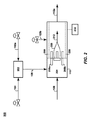
次に図を参照すると、図1A〜図1Dは、本発明の実施形態による、4つの代替可能な例示的な制御概略図を示す。特に、図1Aは基本的な例示的システムである。システム100は、少なくとも一次希釈ストリーム102aと二次希釈ストリーム102bに分かれる高濃度二酸化炭素(CO2)ストリーム102と、ある酸素対CO2比を持つ酸素付加ストリーム106を生成するために、一次希釈ストリーム102aと混合されてもよい酸素供給ストリーム104とを含む。燃焼燃料ストリーム108も供給され、それは実質的にメタン(CH4)から成っていてもよく、または供給源によるが、軽質炭化水素、重質炭化水素、水素(H2)、および二酸化炭素などの不活性ガスの混合物を含んでもよい。燃焼器(たとえば、燃焼器缶)110も供給され、好ましい実施形態では、それは一次燃焼ゾーン110aとバーンアウトゾーン110bの2つの部分に分割され、少なくとも酸素付加ストリーム106と燃焼燃料ストリーム108とを受容し、酸素付加ストリーム106と燃焼燃料ストリーム108を一次燃焼ゾーン110aで混合して所望の火炎温度で燃焼させ、燃焼器の中の一次滞留時間は高温生成物ストリーム(図示せず)を平衡近傍状態で生成するには十分であり、次に高温生成物ストリームをバーンアウトゾーン110bの中で二次希釈ストリームによって希釈して燃焼生成物ストリーム112aを生成し、それが膨張生成物ストリーム112bを生成するために負荷コントローラ111’に操作可能に接続される膨張デバイス111(たとえば、ガスタービンまたは高温エキスパンダー)に供給されてもよいように構成される。膨張生成物ストリーム112bは、少なくとも高濃度ストリーム102の一部を形成するストリーム113と、オイル増進回収(EOR)、滞溜、または別の目的のために使用されてもよい二次ストリーム128を形成するために分割されてもよい。システム100は、燃焼生成物ストリーム112aまたは膨張生成物ストリーム112bの温度および酸素含有量を、それぞれ測定するように構成される、少なくとも一つの温度センサー114と酸素アナライザー126をさらに含む。温度センサー114の温度データは、二次希釈ストリーム102bの流量を制御し、燃焼生成物ストリーム112aの温度を調節するために使用される。酸素供給104の流量は、燃焼燃料供給108の流量に比例して調節される。酸素アナライザー126の酸素データは、実質的に化学量論的燃焼が達成されるまで、燃焼燃料供給108に対する酸素供給ストリーム104の流量の割合因子を調節するために使用される。
Referring now to the figures, FIGS. 1A-1D show four alternative exemplary control schematics according to embodiments of the present invention. In particular, FIG. 1A is a basic exemplary system. The
さらに図1を参照すると、システム100は、一次希釈ストリーム102aを制御するための第1の流量コントローラ116aと、酸素供給ストリーム104を制御するための第2の流量コントローラ118と、燃焼燃料ストリーム108を制御するための第3の流量コントローラ120と、二次希釈ストリーム102bを制御するための第4の流量コントローラ116bと操作可能に接続されている中央コントローラ115をさらに含む。中央コントローラ115は、燃焼生成物ストリーム112aまたは膨張生成物ストリーム112b中の未燃焼酸素の量を判定し、これらの測定値を酸素供給ストリーム104の流量を制御するために使用する、温度センサー114および酸素センサー126に接続されていてもよい。中央コントローラ115は、負荷状態の変化に応じて所望の化学量論を維持するために、燃焼燃料ストリーム108および酸素供給ストリーム104の流量を制御してもよい。
Still referring to FIG. 1, the
高濃度二酸化炭素(CO2)ストリーム(すなわち「希釈供給ストリーム」)102は、都合の良いどのような供給源から供給されてもよい。たとえば、少なくとも希釈供給ストリーム102の一部は、再循環ストリーム113を介して膨張生成物ストリーム112bの少なくとも一部を流用し、または分割することにより供給されてもよい。しかしながら、システム100は、外部パイプラインネットワーク、高濃度ガス井戸、ガス処理プラント、または他の供給源などの高濃度の別の供給源の近くに配置されてもよい。さらに、再循環ストリーム113は、未反応酸素または炭化水素などの潜在的に危険性があるまたは望ましくない成分を除去するために、膜、分子篩、吸収、吸着、または他のシステムのような濾過システムなどのいくつかの処理を含んでもよい。特に、酸素アナライザーが膨張生成物ストリーム112bに高濃度の酸素が含まれることを検出した場合には、膨張生成物ストリーム112bを、二次希釈ストリーム102bのように、希釈するために使用するべきではない。同様に、高濃度の未反応炭化水素は、燃焼器110によって異なるが受け入れることもできず、二次希釈ストリーム102bとして使用される前に、除去または分離される必要がある場合がある。しかしながら、燃焼生成物ストリーム112aは実質的に化学量論的燃焼が実施され、約3.0体積パーセント(体積%)未満の酸素、または約1.0体積%未満の酸素、または約0.1体積%未満の酸素、またはさらに約0.001体積%未満の酸素と、約3.0体積パーセント(体積%)未満の炭化水素、または約1.0体積%未満の炭化水素、または約0.1体積%未満の炭化水素、またはさらに約0.001体積%未満の炭化水素を含有するべきであることが好ましく、意図される。
The concentrated carbon dioxide (CO 2 ) stream (or “diluted feed stream”) 102 may be supplied from any convenient source. For example, at least a portion of the diluted
二次ストリーム(すなわち「残余ストリーム」)128は、高濃度二酸化炭素を必要とする別のプロセスに使用するために販売されてもよく、またはオイル増進回収(EOR)、滞溜、または別の目的のために圧縮されて地表貯留部に注入されてもよい。再循環ストリーム113と同様に、ストリーム128は、窒素酸化物(NOx)または酸素のような潜在的不純物または反応物を除去するために、使用前にいくつかの調節が必要な場合がある。もう一度述べるが、ストリーム104は実質的に窒素を含有せず、ストリーム112aは実質的に化学量論的に燃焼されるので、約3.0体積パーセント(体積%)未満の酸素、または約1.0体積%未満の酸素、または約0.1体積%未満の酸素、またはさらに約0.001体積%未満の酸素と、約3.0体積パーセント(体積%)未満のNOx、または約1.0体積%未満のNOx、または約0.1体積%未満のNOx、またはさらに約0.001体積%未満のNOxを含有すべきであることが好ましく、意図される。
The secondary stream (or “residual stream”) 128 may be sold for use in another process that requires high concentrations of carbon dioxide, or oil enhanced recovery (EOR), stagnation, or another purpose May be compressed and injected into the surface reservoir. As with
酸素供給ストリーム104は、高純度の酸素を供給する空気分離ユニット(ASU)または他のプロセスまたはシステムによって提供されてもよい。分離された窒素は、米国特許出願番号61/072,292号に開示されている窒素注入井などの別の関連するプロセスで使用されてもよい。1つの例示的な実施形態では、酸素供給ストリーム104は、残りの部分にアルゴンを含む約90体積%から約99.9体積%の酸素を含有してもよく、微量の窒素および二酸化炭素を含有してもよい。別の例示的な実施形態では、酸素供給ストリームは、約4体積%から約5体積%のアルゴンと約0.2体積%未満の二酸化炭素を含む約95体積%から約96体積%の酸素を含有してもよい。
The
中央コントローラ115は、流量および組成などのデータ入力を受け入れ、たとえば、流量を調節するために使用できるバルブ、ポンプ、コンプレッサー、およびその他のデバイスを介して流量を制御する信号を送信するように構成される、いずれかのタイプの制御システムであってもよい。1つの例示的な実施形態では、中央コントローラ115は、キーボードおよびマウスなどのユーザ入力装置、モニタおよびスピーカなどのユーザ出力装置を備えるプログラム可能なコンピューターを含んでもよく、能動メモリ(RAM)を使用して動作してもよく、ハードディスクドライブ、光学式ドライブ、ネットワークドライブ、およびLAN、WAN、Wi−Fiを介したデータベース、または他の外部ネットワークに操作可能に接続されてもよい。
The
流量コントローラ116a、116b、118、および120は、中央コントローラ115からの信号を受信して処理するためのプログラム可能な自動コントローラを含んでもよく、実質的にガス状のストリームの流量を増減させる流量バルブまたはベーン、ベント、または他の手段に操作可能に接続されてもよい。さらに、例示的な一実施形態では、流量コントローラ116a、116b、118、および120は、流量センサーおよび/または組成物センサーに操作可能に接続されてもよく、それらは流量コントローラによって制御されるそれぞれのストリームの流量の変化を検証するなどのために追加的なデータ入力ができる。火炎安定性および効果的な制御を維持するために、コントローラ116a、116b、118、および120のいずれか、またはすべてに高速コントローラを利用することが有益である。
The
流量コントローラ116bは、前述のような能動センサーであってもよいが、例示的な一実施形態では、二次希釈ストリーム102bの流量を制御できなくともよい。たとえば、燃焼器110は、燃焼器110の中で希釈と温度を制御するように設計された特定のパターンおよび大きさの孔を持つ、一つ以上の冷却ポート(たとえば、希釈孔)を有するライナーを含んでもよい。それ故に、二次希釈ストリーム102bの流量は、主として燃焼器110の冷却ポートのハードウェア設計および希釈供給ストリーム102の圧力、温度および組成に依存する。さらに、運転停止、二次希釈ストリーム102bの汚染、または他のいくつかの理由がある場合に、流量コントローラ116bは、二次希釈102bの流量を止めるためにさらに有益である。いくつかの実施形態では、中央コントローラ115は、温度センサー114および酸素アナライザー126などの特定のセンサーに対しては、多数決投票方式(two out of three voting )をさらに含んでもよい。中央コントローラ115を含む制御システムは、システム100を制御できなくなった場合に下流の機械を保護するために、少なくとも一つの安全保護装置および/または運転停止ロジックならびに警報を備えるように構成されてもよい。
The
温度センサー114は単一センサーであってもよく、または、正確な温度測定値を確保するために、燃焼生成物ストリーム112aまたは膨張生成物ストリーム112bの中および周囲に、冗長性のある予備センサーまたはアレイセンサーを追加的に含んでもよい。選択されたセンサーは、高耐熱性を有し、華氏約2,000度(°F)以上、または約2,200°F以上の温度で有効に動作することができるべきであるが、いずれかの種類の適切な温度センサーが使用されてもよい。記述される発明システム100のいくつかの例示的な実施形態では、温度センサー114はデータを直接流量コントローラ116bに送信してもよく、またはデータを、その後に流量コントローラ120の応答を制御する中央コントローラ115に送信してもよい。または、温度センサー114は、データを直接燃焼燃料ストリーム流量コントローラ120に送信してもよい。さらにおよびまたは、温度センサー114は排気口近くの燃焼器110の中側からデータを取得し、または出力後のバーンアウトゾーン110bの下流の燃焼生成物ストリーム112aおよび膨張生成物ストリーム112bに沿った複数の場所でデータを取得し、または、それらのいくつかの組み合わせでデータを取得してもよい。ストリーム112aおよび112bの温度は、特定の動作パラメーターの中で制限されるべきであり、それは使用中の装置、燃焼燃料ストリームおよび使用可能な他の入力ストリームの種類、残余ストリーム128の使い道、および他の要因に強く依存する。
The
一般に、一次燃焼ゾーン110aの温度は、NOxの生成を避けるために約3,500°F未満であるべきであり、ほとんどの市販の燃焼器110は該温度を超えると動作できないが、燃焼器110の材料がより高温度で動作することができ、システム100に窒素が存在しない場合には、この制限はより高い温度に設定されてもよい。エキスパンダー111の入口での温度は、好ましくは約2,500°F未満である。該高温は、すすを生成する望ましくない多環芳香族炭化水素(PAH)の形成の一因でもある。しかしながら、一次燃焼ゾーン110aの温度は、火炎燃え切りを避けるために充分に高くなければならならず、それは一次燃焼ゾーンに進入した反応物の温度および特定の燃料108から得られる発熱量に基づいて、CO2に対する酸素の比を調整することによって実施され、および、オイル増進回収(EOR)またはシステム100の希釈に使用される前に、制限的な調整が要求される膨張生成物ストリーム112bを生成するために、実質的にすべての酸素(O2)および炭化水素を効率的に燃焼させるために充分に高くなければならならない(たとえば、化学量論的燃焼温度)。多くの場合に、燃焼生成物ストリーム112aの好ましい温度は、少なくとも約1,500°Fから高くても約2,500°Fの範囲であり、または少なくとも約1,600°Fから高くても約1,900°Fの範囲である。燃焼反応物の中に改良された構成材料がなく、窒素が存在するために上限を上げる場合を除いて、多くの場合に、一次燃焼ゾーンの中の好ましい断熱火炎温度は、少なくとも2,450°Fから高くても3,500°Fの範囲である。
In general, the temperature of the
酸素アナライザー126は単一センサーであってもよく、正確な測定を確保するために、複数の場所に冗長性のある追加のセンサー、または様々なアレイセンサーを含んでもよい。たとえば、中央コントローラ115および/または酸素供給ストリーム流量コントローラ118の1つにフィードバックするように、複数のラムダセンサーまたは広域ジルコニアO2センサーが使用されてもよい。ラムダセンサーが使用される場合には、燃焼生成物ストリーム112aの酸素含有量の化学量論的係数が1.0未満から1.0を超える間で変化するように、酸素供給ストリーム104中の酸素と燃焼燃料ストリーム108中の燃料との比をディザ(dither)させるように中央コントローラ115が構成されてもよい。ディザリングプロセスは、内燃機関に対して自動車産業で使用されているものと類似している。いずれの場合にも、燃焼生成物ストリームの酸素含有量は低いことが好ましく、約3.0体積パーセント(体積%)未満から、約1.0体積%未満、約0.1体積%未満、約0.001体積%未満の範囲が好ましい。次に酸素の量が非常に大い場合には、酸素供給ストリーム104の流量が低減される。これによって順に火炎温度を下げることができ、上記で論じたように、燃焼燃料ストリーム108の流量の調節が要求される。
The
図1Bは、図1Aに示すように基本的な例示的なシステムを示すが、さらに生成物ストリーム112aおよび112bを処理または調整するように構成される追加的な、オプションの特徴を含む。このように、図1Bは、図1Aを参照することによってより良く理解されるであろう。システム140は、図1Aに関する開示されたすべての特徴を含むが、さらには、流量と組成を持つ生成物ストリーム112aおよび112b並びに燃焼燃料バイパスストリーム142の中の酸素および一酸化炭素含有量を低減するように構成される燃焼後触媒作用装置146と、燃焼燃料バイパスストリーム142の流量を制御するための流量コントローラ144とを含む。酸素アナライザー126は、中央コントローラ115を介して直接的または間接的に、流量コントローラ144と操作可能に接続されていてもよい。以下でさらに論じるように、燃焼燃料バイパスストリーム142が分割され、またはストリーム128がループする特定の実施形態では、追加の流量コントローラおよび酸素アナライザー(図示せず)が、要求されてもよい。
FIG. 1B shows a basic exemplary system as shown in FIG. 1A, but further includes additional optional features configured to process or
触媒作用装置146は、単一デバイス、または直列または並列に接続された複数のデバイスであってもよいが、好ましくは動作させるためにわずかなパワーしか必要としない小さなデバイスである。特に、触媒作用装置146は、排気規制を満たすために、熱回収蒸気発生器(HRSG’s)で通常使用される、一酸化炭素低減触媒および/または酸素還元触媒であってもよい。該システムは、一般に大量の酸素を除去するように設計されてはいないが、大量の酸素が膨張生成物ストリーム112bに残る場合には、膨張生成物ストリーム112bは、圧縮され、オイル増進回収(EOR)に注入される前に、触媒作用装置146の中を一回以上通って再循環される必要がある場合がある。このように、いくつかの実施形態では、圧縮注入装置の腐食を避け、および貯留部の中に残る炭化水素と反応できる酸素の注入による貯留部の酸敗を避けるように、注入ストリーム128の酸素が充分に少ないことを確認する(たとえば、約0.5体積パーセント(体積%)未満または約0.1体積%未満の酸素)ために、別の酸素アナライザー(図示せず)が触媒作用装置146の後に必要である場合がある。
燃焼燃料バイパスストリーム(たとえば、燃焼燃料ストリームの第2の部分)142は、再利用フローストリーム113が膨張生成物ストリーム112bから分割される場所から下流で、膨張生成物ストリーム112bと混合するように構成され、好ましくは触媒作用装置146の上流で導入され、酸素除去効率を改善するために追加的な炭化水素が触媒作用装置146で使用されてもよい。しかしながら、いくつかの代替実施形態では、バイパスストリーム142は、触媒作用装置146の前および後で、分割および導入されてもよい。EORストリーム128が折り返して触媒作用装置146に戻る実施形態では、触媒作用装置146に折り返して戻る前に、バイパスストリーム142の一部をEORストリーム128の中に導入することが都合がよい。好都合なことに、バイパスストリーム142は、圧縮および貯留部に注入される前に、EORストリーム128中の酸素の体積パーセントを低減するように構成され、実質的に圧縮および注入装置の腐食を避け、注入貯留部の中に残る炭化水素の酸化を避ける。
Combustion fuel bypass stream (eg, second portion of combustion fuel stream) 142 is configured to mix with
図1Cは、図1Bの実施形態の説明に開示された特徴を含む、または含まなくともよい、図1Aのシステムの第3の例示的な実施形態を示す。このように、図1Cは、図1Aおよび図1Bを参照してよりよく理解されるであろう。システム150は、生成物ストリーム112aおよび/または112bの組成物中の炭化水素量を測定するように構成される炭化水素アナライザー152と、流量コントローラ154によって制御される高品質燃料ガス供給108aと、流量コントローラ156によって制御される低発熱量燃料ガス供給108bとを含む。流量コントローラ156は、炭化水素アナライザー152に直接接続されてもよく、および/または中央コントローラ115を介して接続されてもよい。中央コントローラ115と直接接続されてもよい、または酸素供給コントローラ118を介して接続されてもよい総和コントローラ158と、流量コントローラ154、156、およびオプションの120は操作可能に接続されてもよい。
FIG. 1C illustrates a third exemplary embodiment of the system of FIG. 1A that may or may not include features disclosed in the description of the embodiment of FIG. 1B. Thus, FIG. 1C will be better understood with reference to FIGS. 1A and 1B. The
高品質燃料ガスストリーム108aは、実質的に純粋なメタン(たとえば、約99体積%)を含んでいてもよく、または、水素、高級炭化水素(C3+)またはそれらの組み合わせなどの「スパイク(spiking)」燃料ガスを含んでもよい。高品質燃料ガスストリーム108aの組成物は、システム150の要求、およびさまざまな燃料タイプの入手可能性に応じて主に変化するが、好ましくは大量の不活性ガス(たとえば、窒素、二酸化炭素等)または酸性ガス(たとえば、二酸化硫黄、硫化水素等)を含まない。高品質燃料ガスストリーム108aは、すべての妥当な供給源から供給されてもよいが、非常に遠くから輸入されるよりも、好ましくは近隣のガス生成田から得られる。特に、ストリーム108aが水素の場合には、近隣のガス生成田からのガス生成ストリームで実施される自己熱改質(ATR)プロセスから供給されてもよい(図示せず)。
The high quality
低発熱量燃料ガスストリーム108bは、約80体積%未満のメタン、約60体積%未満のメタン、約40体積%未満のメタン、またはさらに約20体積%未満のメタンを含んでいてもよい。低発熱量ストリーム108bは、エタンおよびプロパンなどの少量の重質炭化水素を含有してもよい。ほとんどの場合、ストリーム108bの残余の大部分は、二酸化炭素などの不活性ガスであるが、場合によっては、少量の窒素、硫化水素、ヘリウム、および他のガスが存在する。好ましくは、二酸化炭素以外のすべての非炭化水素と不活性ガスは、混合および燃焼する前にストリーム108bから分離される。
The low heating value
1つの例示的な実施形態では、2つの炭化水素含有ストリーム108aおよび108bの流量と組成は、燃焼器110を動作させるために必要とされる酸素を演算するため、および酸素供給流量コントローラ118のための設定ポイントを提供するために使用される。演算によって、燃焼器110の化学量論的燃焼のために必要とされる酸素の量が提供される。ストリーム108aおよびストリーム108bの供給源に依存するが、ストリームの流量および組成は、システム150の寿命に応じて変化してもよい。たとえば、低発熱量燃料ガス108bは、生産初期にはメタンを多く含有する(たとえば、約80体積%よりも多い)EOR井から供給されてもよい。このような場合には、ほとんど、またはまったく高品質燃料ガスストリーム108aを通じた流れがなくともよい。しかしながら、ブレークスルーが発生する場合には、低発熱量燃料ガスストリーム108bからの流れのメタン含有量は非常に小さい(たとえば、約20体積%未満)。このような場合には、高品質燃料ガスストリーム108aの流量は増加し、炭化水素を燃焼燃料ストリーム108に添加する。
In one exemplary embodiment, the flow rates and compositions of the two hydrocarbon-containing
図1Dは、図1Bおよび図1Cの実施形態の説明に開示された特徴を含む、または含まなくとも良い、図1Aのシステムの第4の例示的な実施形態を示す。このように、図1Dは、図1A〜図1Cを参照してよりよく理解されるであろう。システム160は、流量および組成物を持つ高濃度CO2補給ストリーム108cと、それに操作可能に取り付けられた流量コントローラ162をさらに含む。CO2補給酸素供給ストリーム108cは、ストリーム108aおよび108bと混合されてもよく、システム160の寿命にわたって実質的に一定の組成を有する燃焼燃料ガスストリーム108を生成する。アプローチはシステム150と類似しているが、燃焼器の物理的特徴は、特に108およびさらに可変組成である108bを含む燃焼燃料の組成用に設計される。ストリーム108cは膨張生成物ストリーム112bから分割されてもよいし、または別の供給源が起源であってもよい。
FIG. 1D shows a fourth exemplary embodiment of the system of FIG. 1A that may or may not include features disclosed in the description of the embodiment of FIGS. 1B and 1C. Thus, FIG. 1D will be better understood with reference to FIGS. 1A-1C. The
図1Eは、図1A〜図1Dのシステムの第4の例示的な実施形態を示す。このように、図1Eは、図1A〜図1Dを参照してよりよく理解されるであろう。システム170は、実質的に炭化水素および二酸化炭素(CO2)を含有し、初期燃料対CO2比を有する燃焼燃料ストリーム108と;実質的に酸素と二酸化炭素(CO2)を含有する酸素付加ストリーム106であって、該燃焼燃料ストリーム108と該酸素付加ストリーム106は混合されて、最適な等量比を満足させるように構成される混合された燃料対酸素比を有し、最適な燃焼温度を提供するように構成される混合された初期CO2対燃料比を有する燃焼器入口ストリーム172を形成する酸素付加ストリーム106と;二次希釈ストリーム102bと;燃焼器入口ストリーム172を燃焼させて実質的に水と二酸化炭素を含む高温生成物ストリーム174を生成するように構成される燃焼器110であって、該高温生成物ストリーム174は二次希釈ストリーム102bと混合され、ある温度と最終的なCO2対燃料比を有する燃焼生成物ストリーム112aを生成する燃焼器110とを含む。
FIG. 1E shows a fourth exemplary embodiment of the system of FIGS. 1A-1D. Thus, FIG. 1E will be better understood with reference to FIGS. 1A-1D. The
いくつかの例示的な実施形態では、燃焼燃料ストリーム108中の炭化水素は実質的にメタンを含み、燃料対酸素のモル比は、約1.9:1のモル燃料対モル酸素から、約2.1:1のモル燃料対モル酸素、または約1.95:1のモル燃料対モル酸素から、約2.05:1のモル燃料対モル酸素の範囲である。これらのモル比は、0.9:1から約1.1:1の化学量論的比とおおよそ等価である。さらに例示的な実施形態では、燃焼燃料ストリーム108中の炭化水素は実質的にメタンを含み、最終的なCO2対燃料比は、約10:1のモルCO2対モル燃料から約30:1のモルCO2対モル燃料、または約15:1のモルCO2対モル燃料から約25:1のモルCO2対モル燃料、または約20:1のモルCO2対モル燃料から約23:1のモルCO2対モル燃料の範囲である。
In some exemplary embodiments, the hydrocarbon in the
少なくとも一つの例示的な実施形態では、システム170は、ある流量と組成を有する高品質燃料ガスストリーム108aと;ある流量と組成を有する低発熱量燃料ガスストリーム108bと;高品質燃料ガスストリーム108aと低発熱量燃料ガスストリーム108bと混合するように構成され、燃焼燃料ストリーム108を形成し、燃焼燃料ストリーム108の初期燃料対CO2の比を一定に維持する、高濃度補給ストリーム108cをさらに含む。追加の実施形態は、ある流量と組成を有する酸素供給ストリーム104と;酸素供給ストリーム104と混合するように構成され、酸素付加ストリーム106を形成する、ある流量と組成を有する高濃度混合ストリーム102aを含んでもよい。
In at least one exemplary embodiment,
さらにもう一つの例示的な実施形態では、システム170は、燃焼生成物ストリーム112aの温度および/または膨張生成物ストリーム112b(およびオプションで高温生成物ストリーム174)の温度を測定するように構成される少なくとも一つの温度センサー114であって、ストリーム112aまたはストリーム112bの温度は、燃焼温度を調節するために、高濃度CO2混合ストリーム102a、高濃度CO2補給ストリーム108c、および二次希釈ストリーム102bの少なくともいずれか一つの流量を演算することに使用される少なくとも一つの温度センサー114と;生成物ストリーム112aおよび/または112bの組成中の酸素の量を測定するように構成される少なくとも一つの酸素アナライザー126であって、生成物ストリーム112a、生成物ストリーム112b中の酸素の量は、実質的に化学量論的燃焼を達成するように酸素供給ストリーム104の流量を最適化するために使用される少なくとも一つの酸素アナライザー126と;生成物ストリーム112a、生成物ストリーム112bの組成中の炭化水素の量を測定するように構成される少なくとも一つの炭化水素アナライザー152であって、生成物ストリーム112a、生成物ストリーム112bの組成物中の炭化水素の量は、実質的に化学量論的燃焼するように、酸素供給ストリーム104の流量を最適化するために使用される少なくとも一つの炭化水素アナライザー152を含む。システム170は、ある負荷と該負荷を測定するように構成された負荷コントローラ111’を有するガスタービン111を含んでもよく、負荷の測定は、負荷の変化である混合された燃料対酸素の比を維持するために使用される。
In yet another exemplary embodiment, the
図2は、図1A〜図1Dの代替の例示的なシステムに使用されるように構成されてもよい、例示的な燃焼器の概略図を示す。このように、図2は、図1A〜図1Dを参照してよりよく理解されるであろう。燃焼器システム200は、第1の混合ゾーン202、第2の混合ゾーン204、初期高温度一次燃焼ゾーン205、バーンアウトゾーン206、およびオプションの燃料注入ノズル208aおよび燃料注入ノズル208bを含む。高温生成物ストリーム(すなわち「一次燃焼生成物ストリーム」)212は、一次燃焼ゾーン205から生成される。いくつかの例示的な実施形態では、高圧力燃焼プロセス(たとえば、約10気圧より大きい)が利用されてもよいことに注意されたい。
FIG. 2 shows a schematic diagram of an exemplary combustor that may be configured for use with the alternative exemplary system of FIGS. 1A-1D. Thus, FIG. 2 will be better understood with reference to FIGS. 1A-1D.
第1の混合ゾーン202は、一次希釈ストリーム102aを酸素供給ストリーム104と混合し、酸素付加ストリーム106を形成するように構成される。第2の混合ゾーン204は、酸素付加ストリーム106と燃焼燃料ストリーム108を混合するように構成される。一実施形態では、ストリーム106とストリーム108は第2の混合ゾーン204で事前に混合されてもよく、次に一次燃焼ゾーン205の中に直接流れる。非事前混合と称する、別の実施形態では、拡散バーナタイプの配置にあるように、第2の混合ゾーン204および一次燃焼ゾーン205は重複し、混合と一次燃焼が同時に発生する。一次燃焼ゾーン205は、バーナ、火炎、および高温生成物ストリーム212を生成する燃焼反応自体を含む。バーンアウトゾーン206では、二次希釈ストリーム102bを燃焼器110に配送し、燃焼器110および燃焼生成物ストリーム112aの温度を調節する。
The
燃焼器110のいくつかの例示的な実施形態では、バーンアウトゾーン206は、燃焼器110のライナーを冷却および急冷するように構成される一連の孔を有する受動的な希釈ゾーンと;一次燃焼生成物ストリーム212と混合するために、二次希釈ストリーム102bの少なくとも一部分を燃焼器110に能動的に配送するように構成される、少なくとも一つの急冷ポートを有する能動希釈ゾーンと;バーンアウトゾーン206を介して、温度パターンを能動的に制御する一連の段階的冷却ポートと;それらの組み合わせのいずれか1つを含む。さらに、バーンアウトゾーン206は、火炎の吹き消えの兆候である、燃焼器110の圧力オシレーションを測定して監視するために、圧力トランスデューサーまたは他のセンサー210を含んでもよい。酸素アナライザー(図示せず)も、酸素フィードバックループに別の入力を提供するために燃焼器110に含まれてもよい。
非事前混合配置の1つの例示的な実施形態では、燃焼燃料ストリーム108aおよび108bは、それぞれのストリームの体積流量に基づいて構成される、分離したノズル208aおよびノズル208bに導入されてもよく、または単一注入器の中を通って、混合して組み合わせられた燃焼燃料ストリーム108として注入されて混合されてもよい。
In some exemplary embodiments of the
In one exemplary embodiment of a non-premixed arrangement, the
燃焼器110の中の酸素付加ストリーム106と燃焼燃料ストリーム108の組み合わせは、最小断熱火炎温度と火炎安定性を維持するように構成され、酸素付加ストリーム106中のすべて、またはほとんどすべての酸素を燃焼する(たとえば、化学量論的反応が好ましい)。発熱量という意味では、酸素付加ストリーム106は発熱量を持たず、高品質燃料ガスストリーム108aは比較的高い値(たとえば、少なくとも500イギリス熱単位毎標準立方フィート(BTU/scf)から約950BTU/scfである)を持ち、低発熱量燃料ガスストリーム108bは比較的低い発熱量(たとえば、約150BTU/scfから約450BTU/scf)を持つ。
燃焼器110は、標準的な外部燃焼器であってもよく、または、特別注文または修正された燃焼器であってもよい。適用できる燃焼器のタイプの例には、oxyClaus(登録商標)バーナ、部分酸化(POX)バーナ、自己熱改質(ATR)バーナ、およびガスタービン拡散燃焼器が挙げられる。それぞれのバーナタイプは、実質的にCO2ストリームと連動するために、いくつかの変更が必要である場合があることに注意されたい。
The combination of the
The
1つの例示的な実施形態では、第2の混合ゾーン204並びにノズル208aおよびノズル208bは、均質な混合物を得ることを保証するために、燃焼燃料ストリーム108と酸素付加ストリーム106とを激しい乱流として混合するように構成されてもよい。動作中は、一次燃焼ゾーン205は約2,200℃までの温度を生成する。冷却ガス102bの添加によって、燃焼生成物ストリーム112aは、バーンアウトゾーン206に入るにつれて、約1,400℃まで冷却されることが期待される。追加の冷却ガス102bは、一種の「ガス外層(gas envelope)」を形成するバーンアウトゾーン206の外壁を通じて導入されてもよく、燃焼器110の壁は火炎205よりも著しく冷却されることを維持する。1つの例示的な実施形態では、必要な場合には冷却ストリーム102bの炭化水素は除去され、すすの発生を最小にする。別の例示的な実施形態では、燃焼は、約10気圧を超えるなどの大気圧よりも高い状態で発生する。反応によって、以下の式によって示されるように水(蒸気)と二酸化炭素が発生する(チャンバに入った二酸化炭素は一般に未反応のままである):
CH4+2O2=2H2O+CO2
In one exemplary embodiment, the
CH 4 + 2O 2 = 2H 2 O + CO 2
図3は、図1A〜図1Dのシステムの動作方法の例示的なフローチャートである。このように、図3は、図1A〜図1Dを参照してよりよく理解されるであろう。方法300はブロック302から始まり、次に304では、それぞれのストリームがある流量とある組成を有する、高濃度CO2ストリーム102、酸素供給ストリーム104、および燃焼燃料ストリーム108を供給し;306では、それぞれのストリームがある流量を有する、高濃度CO2ストリーム102を一次希釈ストリーム102aと二次希釈ストリーム102bに分割し;308では高濃度CO2ストリームの全体の流量とは無関係に一次希釈ストリームの流量を調節し;310では、酸素付加ストリーム(すなわち、「合成空気」)106を生成するために、一次希釈ストリーム102aと酸素供給ストリーム104とを混合し;312では、ある温度と組成を有する燃焼生成物ストリーム112aを生成するために、酸素付加ストリーム106と燃焼燃料ストリーム108とを、燃焼器110の一次燃焼ゾーン110aで燃焼させ;314では燃焼生成物ストリーム112aの酸素含有量を検出し;316では燃焼生成物ストリーム112aが実質的に化学量論的になるまで、検出された酸素含有量を使用して酸素供給ストリーム104の流量を調節することを含む。一実施形態では、方法300は、314で燃焼生成物ストリーム112aの温度を検出し、316で検出された温度を使用して、燃焼の温度を調節するために一次希釈ストリーム102aの流量を調節することを含む。一実施形態では、該方法は、318で燃焼生成物ストリーム112aの一部分をオイル増進回収(EOR)プロセスに向けることを含む。
FIG. 3 is an exemplary flowchart of a method of operation of the system of FIGS. 1A-1D. Thus, FIG. 3 will be better understood with reference to FIGS. 1A-1D. The
いくつかの例示的なガスストリームの組成を、単一ガス生成田または異なるガス生成田での生産の異なる段階におけるガスストリームの例として、以下の表に示す。表1では、生産井の生産開始時点または生産開始時点に近い時点での特定のストリーム組成および流量を示す。

表2は、CO2ブレークスルー(breakthrough)後の生産井の特定のストリームの組成および流量を示す。
本発明はさまざまな変更形態および代替形態が可能であり、上記で論じた例示的な実施形態は、ほんの一例として示したものである。しかしながら、当然のことながら、本発明はここに開示された特定の実施形態に限定されることを意図していない。実際、本発明は、添付の特許請求範囲の真の精神および範囲内にある、すべての代替形態、変更形態、および均等形態を含む。 While the invention is susceptible to various modifications and alternative forms, the exemplary embodiments discussed above are given by way of illustration only. However, it should be understood that the invention is not intended to be limited to the specific embodiments disclosed herein. Indeed, the invention includes all alternatives, modifications, and equivalents that fall within the true spirit and scope of the appended claims.
Claims (38)
高濃度二酸化炭素(CO2)ストリームと、
前記高濃度CO2ストリームの全体の流量を調節し、前記高濃度CO2ストリームを流量を持つ一次希釈ストリームと流量を持つ二次希釈ストリームとに分割するように構成される少なくとも一つのCO2流量調節デバイスであって、さらに前記高濃度CO2ストリームの全体の流量とは無関係に前記一次希釈ストリーム流量を調節するように構成される前記少なくとも一つの流量調節デバイスと、
流量を持つ酸素供給ストリームと、
前記酸素供給ストリームの流量を調節するように構成された少なくとも一つの酸素流量調節デバイスと、
前記一次希釈ストリームと前記酸素供給ストリームとを混合し、流量と酸素対CO2比を持つ酸素付加ストリームを生成するように配置された混合デバイスと、
流量と組成を持つ燃焼燃料ストリームと、
少なくとも一次燃焼ゾーンとバーンアウトゾーンから成る燃焼器であって、前記一次燃焼ゾーンの中で、化学量論的状態に近いがわずかにリッチ状態で高温生成物ストリームを生成するために充分な火炎温度と一次滞留時間とで、前記酸素付加ストリームと前記燃焼燃料ストリームを混合して燃焼させるように構成される燃焼器とを含むシステム。 A combustion system,
A highly concentrated carbon dioxide (CO 2 ) stream;
The high-concentration CO 2 to adjust the overall flow rate of the stream, the high-concentration CO 2 at least one of CO 2 flow rate is configured to divide the stream into a secondary dilution stream with the primary dilution stream and the flow rate with the flow rate A regulating device, further comprising the at least one flow regulating device configured to regulate the primary dilution stream flow rate independent of the overall flow rate of the high concentration CO 2 stream;
An oxygen supply stream having a flow rate;
At least one oxygen flow adjustment device configured to adjust the flow rate of the oxygen supply stream;
A mixing device arranged to mix the primary dilution stream and the oxygen feed stream to produce an oxygen addition stream having a flow rate and an oxygen to CO 2 ratio;
A combustion fuel stream having a flow rate and composition;
A combustor comprising at least a primary combustion zone and a burnout zone, wherein a flame temperature sufficient to produce a hot product stream in the primary combustion zone that is near stoichiometric but slightly rich And a combustor configured to mix and burn the oxygenated stream and the combustion fuel stream at a primary residence time.
前記高温生成物ストリームよりも低温度を持つ燃焼生成物ストリームを生成するために、前記バーンアウトゾーンの中で、前記高温生成物ストリームを前記二次希釈ストリームで希釈するように前記燃焼器が構成されるシステム。 The system of claim 1, comprising:
The combustor is configured to dilute the hot product stream with the secondary dilution stream in the burnout zone to produce a combustion product stream having a lower temperature than the hot product stream. System.
前記一次燃焼ゾーンの中で化学量論的状態に近い燃焼を生成するために、前記燃焼燃料ストリームの流量に応じて前記酸素供給ストリームの流量を調節するように構成される第1のコントローラと、
燃焼器平均速度と、前記燃焼器の吹き消え限界と、おおよその平衡状態で燃焼生成物ストリームを生成するのに充分な前記燃焼器内での前記一次滞留時間との間で充分なマージンを提供するように構成される、一次燃焼ゾーンの火炎温度を生成するために、前記一次希釈ストリームの流量を制御することによって、前記酸素付加ストリームの酸素対CO2比を調節するように構成される第2のコントローラとを含む制御システムをさらに含むシステム。 The system of claim 2, comprising:
A first controller configured to adjust a flow rate of the oxygen supply stream in response to a flow rate of the combustion fuel stream to produce near- stoichiometric combustion in the primary combustion zone;
Provide sufficient margin between combustor average speed, burn-out limit of the combustor, and primary residence time in the combustor sufficient to produce a combustion product stream at approximate equilibrium Configured to adjust an oxygen to CO 2 ratio of the oxygen addition stream by controlling a flow rate of the primary dilution stream to generate a flame temperature of the primary combustion zone. And a control system including two controllers.
前記燃焼生成物ストリームを膨張させ、前記燃焼生成物ストリームよりも温度が低い膨張生成物ストリームを生成するように構成される膨張デバイスをさらに含むシステム。 The system according to claim 3, wherein
A system further comprising an expansion device configured to expand the combustion product stream and generate an expanded product stream having a lower temperature than the combustion product stream.
前記制御システムは、前記制御システムとCO2流量調節デバイスと操作可能に接続されて、前記燃焼生成物ストリームの温度を測定し、前記制御システムに信号を送信するように構成される少なくとも一つの温度センサーをさらに含み、前記燃焼システムを出た後の位置で所望の温度の二次燃焼生成物ストリームを生成するために、前記制御システムは前記燃焼生成物ストリームの温度に基づいて前記二次希釈ストリームの流量を調節するように構成されるシステム。 5. The system according to claim 4, wherein
The control system is operatively connected to the control system and a CO 2 flow regulation device to measure at least one temperature of the combustion product stream and to send a signal to the control system In order to generate a secondary combustion product stream at a desired temperature at a position after exiting the combustion system, the control system further includes a sensor based on the temperature of the combustion product stream to generate the secondary dilution stream A system configured to regulate the flow rate of the.
前記膨張デバイスの出口から空間を置いて離れた位置で、前記膨張生成物ストリームの中に位置し、前記膨張生成物ストリームの中の酸素含有量を測定し、前記制御システムに信号を送信するように構成される少なくとも一つの酸素センサーをさらに含み、前記制御システムは前記酸素付加ストリーム中の酸素と前記燃焼燃料ストリーム中の燃料との酸素対燃料比を調節するように構成され、前記膨張生成物ストリーム中の酸素含有量がほとんどゼロに近く、酸素の割合が少量だけ増加した場合には、前記膨張生成物ストリーム中の酸素含有量が測定可能となることによって示される実質的に化学量論的な燃焼を達成するシステム。 6. The system according to claim 5, wherein
Located in the expansion product stream at a distance away from the outlet of the expansion device, measuring the oxygen content in the expansion product stream and sending a signal to the control system At least one oxygen sensor configured to: wherein the control system is configured to adjust an oxygen to fuel ratio of oxygen in the oxygenated stream and fuel in the combustion fuel stream; If the oxygen content in the stream is almost close to zero and the proportion of oxygen is increased by a small amount, it is substantially stoichiometric as indicated by the measurable oxygen content in the expanded product stream. System that achieves proper combustion.
前記膨張デバイスを所望の負荷状態に維持するために、前記燃焼燃料ストリームの流量を制御するように構成される少なくとも一つの負荷コントローラをさらに含むシステム。 The system according to claim 6, comprising:
The system further comprising at least one load controller configured to control a flow rate of the combustion fuel stream to maintain the expansion device at a desired load condition.
前記二次希釈ストリームの流量は、前記高濃度CO2ストリームおよび前記二次希釈ストリームの流路中の少なくとも一つの流量制限体による圧力降下に基づいて受動的に制御されるシステム。 The system of claim 1, comprising:
A system in which the flow rate of the secondary dilution stream is passively controlled based on a pressure drop by at least one flow restrictor in the flow path of the high-concentration CO 2 stream and the secondary dilution stream.
少なくとも一つの温度センサーと少なくとも一つの酸素アナライザー、
前記一次希釈ストリームを制御するための第1の流量コントローラ、
酸素供給流量を制御するための第2の流量コントローラ、
燃焼燃料流量を制御するための第3の流量コントローラ、および
前記二次希釈ストリームを制御するための第4の流量コントローラに操作可能に接続されている中央コントローラをさらに含むシステム。 The system according to claim 6, comprising:
At least one temperature sensor and at least one oxygen analyzer over,
The first flow rate controller for controlling the primary dilution stream,
Second flow rate controller for controlling the oxygen supply flow rate,
Third fourth further comprising a system central controller that is operably connected to a flow controller for controlling flow rate controllers, and the secondary dilution stream to control the combustion fuel flow rate.
前記燃焼生成物ストリームは、実質的に水と二酸化炭素(CO2)を含み、前記高濃度CO2ストリームは少なくとも部分的に前記膨張生成物ストリームのCO2部分を含むシステム。 5. The system according to claim 4, wherein
The combustion product stream substantially comprises water and carbon dioxide (CO 2 ), and the high concentration CO 2 stream at least partially comprises the CO 2 portion of the expansion product stream.
前記膨張生成物ストリームのCO2部分の少なくとも一部は、オイル増進回収(EOR)のために利用されるシステム。 The system of claim 10, comprising:
A system in which at least a portion of the CO 2 portion of the expanded product stream is utilized for oil enhanced recovery (EOR).
前記オイル増進回収(EOR)のために利用される前に、前記燃焼生成物ストリーム中の酸素含有量を低減するように構成される、燃焼後触媒作用装置をさらに含むシステム。 The system of claim 11, comprising:
A system further comprising a post-combustion catalysis device configured to reduce the oxygen content in the combustion product stream before being utilized for the enhanced oil recovery (EOR).
前記燃焼燃料ストリームを、前記燃焼器へ入れるように構成される第1の部分と、前記燃焼器を迂回し、オイル増進回収注入ストリームを生成するために、前記燃焼後触媒作用装置の上流で前記膨張生成物ストリームと混合するように構成される第2の部分とに分割するように構成される、前記燃焼燃料ストリームに沿ったストリーム分割器をさらに含むシステム。 The system of claim 12, comprising:
A first portion configured to enter the combustion fuel stream into the combustor and the upstream of the post-combustion catalytic device to bypass the combustor and generate an oil enhanced recovery injection stream configured in the second part and half split to so that is configured to mix the expanded product stream, further comprising a system stream divider along the combustion fuel stream.
前記酸素付加ストリームを生成するために、前記一次希釈ストリームと前記酸素供給ストリームを混合するように構成された、前記燃焼器の上流に位置する第1の混合ゾーンをさらに含むシステム。 The system of claim 1, comprising:
A system further comprising a first mixing zone located upstream of the combustor configured to mix the primary dilution stream and the oxygen feed stream to produce the oxygenated stream.
触媒をさらに含み、前記触媒は前記一次燃焼ゾーンに添加され、燃焼反応に触媒作用を及ぼすシステム。 The system of claim 1, comprising:
A system further comprising a catalyst, wherein the catalyst is added to the primary combustion zone to catalyze a combustion reaction.
前記酸素付加ストリームと前記燃焼燃料ストリームとを混合してほぼ同時に燃焼されるように、前記一次燃焼ゾーンの上流と前記一次燃焼ゾーンの中からなる群から選択される場所で、前記酸素付加ストリームと前記燃焼燃料ストリームとを事前混合するように構成される第2の混合ゾーンをさらに含むシステム。 15. The system according to claim 14, wherein
The oxygen addition stream at a location selected from the group consisting of upstream of the primary combustion zone and within the primary combustion zone so that the oxygen addition stream and the combustion fuel stream are mixed and combusted substantially simultaneously. The system further comprising a second mixing zone configured to premix with the combustion fuel stream.
前記バーンアウトゾーンは、前記燃焼器のライナーを冷却および急冷するように構成される一連の孔を含む受動的な希釈ゾーンと;前記燃焼生成物ストリームと混合するために、前記二次希釈ストリームを前記燃焼器に能動的に配送するように構成される少なくとも一つの急冷ポートを含む能動希釈ゾーンと;バーンアウトゾーンを介して温度パターンを能動的に制御する一連の段階的冷却ポートと;それらの組み合わせのいずれかからなる群から選択される特徴を含むシステム。 The system of claim 12, comprising:
The burnout zone includes a passive dilution zone including a series of holes configured to cool and quench the combustor liner; and the secondary dilution stream for mixing with the combustion product stream. An active dilution zone including at least one quenching port configured to actively deliver to the combustor; a series of gradual cooling ports that actively control the temperature pattern through the burnout zone; A system comprising a feature selected from the group consisting of any of the combinations.
前記酸素付加ストリームは、5体積パーセントの酸素から40体積パーセントの酸素を含有し、前記酸素付加ストリームの残りの部分は、95体積パーセントのCO2から99.9体積パーセントのCO2を含むシステム。 10. The system according to claim 9, wherein
The oxygenation stream contains oxygen of the oxygen or et 4 0 volume percent of 5 percent by volume, the remaining portion of the oxygenation stream 9 5 volume percent of CO 2 through 9 9.9 volume percent CO A system containing two .
流量と組成を持つ高品質燃料ガスストリームと、
前記燃焼燃料ストリームを生成するために、前記燃料ガスストリームと混合するように構成される、流量と組成を持つ低発熱量燃料ガスストリームをさらに含むシステム。 10. The system according to claim 9, wherein
A high quality fuel gas stream with flow rate and composition;
A system further comprising a low heating value fuel gas stream having a flow rate and composition configured to mix with the fuel gas stream to produce the combustion fuel stream.
前記高品質燃料ガスストリームを制御するための第5の流量コントローラと、
前記低発熱量燃料ガスストリームを制御するための第6の流量コントローラと、
前記第5の流量コントローラおよび前記第6の流量コントローラと操作可能に接続され、前記燃焼燃料ストリームの流量および組成を制御し、燃焼温度を調節し、火炎燃え切りを避けるように構成される総和コントローラとをさらに含むシステム。 20. The system according to claim 19, wherein
A fifth flow controller for controlling the high quality fuel gas stream;
A sixth flow controller for controlling the low heating value fuel gas stream;
A summation controller operatively connected to the fifth flow controller and the sixth flow controller and configured to control the flow rate and composition of the combustion fuel stream, adjust the combustion temperature, and avoid flame burnout And further including a system.
前記燃焼生成物ストリームの組成物の炭化水素の量を測定し、および少なくとも前記第6の流量コントローラと操作可能に接続され、前記燃焼器の中の火炎の吹き消えを避けるために、前記低発熱量燃料ガスの量を制御するように構成される少なくとも一つの炭化水素アナライザーをさらに含むシステム。 21. The system of claim 20, wherein
Measuring the amount of hydrocarbons in the composition of the combustion product stream and operably connected to at least the sixth flow controller to avoid blowing out a flame in the combustor; A system further comprising at least one hydrocarbon analyzer configured to control the amount of fuel gas.
前記低発熱量燃料ガスストリームおよび前記高品質燃料ガスストリームと混合し、前記燃焼燃料ストリームを形成するように構成される、流量と組成を持つ高濃度CO2補給ストリームをさらに含み、実質的に一定流量で一定組成の前記燃焼燃料ストリームを生成するために、それぞれのストリームの流量を調節するように構成される総和コントローラと操作可能に接続された第7の流量コントローラと、前記高濃度CO2補給ストリームが操作可能に接続されているシステム。 20. The system according to claim 19, wherein
Wherein the low heating value fuel gas stream and the high quality fuel gas stream and the combined mixed, configured to form the combustion fuel stream further comprises a high-concentration CO 2 supply stream having a flow rate and composition, substantially A seventh flow controller operably connected to the sum controller configured to adjust the flow rate of each stream to produce the combustion fuel stream of constant composition at a constant flow rate; and the high concentration CO 2 A system where supply streams are operably connected.
それぞれのストリームが流量と組成を持つ、高濃度CO2ストリーム、酸素供給ストリーム、および燃焼燃料ストリームを供給する工程と、
前記高濃度CO2ストリームを、それぞれのストリームが流量を持つ一次希釈ストリームと二次希釈ストリームに分割する工程と、
前記高濃度CO2ストリームの全体の流量とは無関係に前記一次希釈ストリームの流量を調節する工程と、
酸素付加ストリームを形成するために、前記一次希釈ストリームと前記酸素供給ストリームとを混合する工程と、
化学量論的状態に近いがわずかにリッチ状態で、燃焼生成物ストリームを生成するために、前記酸素付加ストリームと前記燃焼燃料ストリームとを燃焼器の一次燃焼ゾーンで燃焼させる工程とを含む方法。 A combustion control method comprising:
Supplying a high concentration CO 2 stream, an oxygen feed stream, and a combustion fuel stream, each stream having a flow rate and composition;
Dividing the high-concentration CO 2 stream into a primary dilution stream and a secondary dilution stream each having a flow rate;
Adjusting the flow rate of the primary dilution stream independently of the overall flow rate of the high concentration CO 2 stream;
Mixing the primary dilution stream and the oxygen feed stream to form an oxygenated stream;
Combusting the oxygenated stream and the combustion fuel stream in a primary combustion zone of a combustor to produce a combustion product stream that is near stoichiometric but slightly rich .
前記燃焼生成物ストリームの酸素含有量を検出する工程と、
前記検出された酸素含有量を使用して、前記燃焼生成物ストリームが実質的に化学量論的になるまで前記酸素供給ストリームの流量を調節する工程をさらに含む方法。 24. The method of claim 23, comprising:
Detecting the oxygen content of the combustion product stream;
The method further comprising adjusting the flow rate of the oxygen feed stream using the detected oxygen content until the combustion product stream is substantially stoichiometric.
前記燃焼生成物ストリームの温度を検出する工程と、
前記検出された温度を使用して燃焼の温度を調節するために、前記燃焼器のバーンアウトゾーンへの前記二次希釈ストリームの流量を調節する工程をさらに含む方法。 25. The method of claim 24, comprising:
Detecting the temperature of the combustion product stream;
Adjusting the flow rate of the secondary dilution stream to the burnout zone of the combustor to adjust the temperature of combustion using the detected temperature.
高品質燃料ガスストリーム、低発熱量燃料ガスストリーム、および前記一次希釈ストリームを供給する工程と、
前記燃焼燃料ストリームを形成するために、前記高品質燃料ガスストリームを前記低発熱量燃料ガスストリームおよび前記一次希釈ストリームと混合する工程とをさらに含む方法。 26. The method of claim 25, comprising:
Supplying a high quality fuel gas stream, a low heating value fuel gas stream, and the primary dilution stream;
Mixing the high quality fuel gas stream with the low heating value fuel gas stream and the primary dilution stream to form the combustion fuel stream.
前記高濃度CO2ストリーム、前記酸素供給ストリーム、前記高品質燃料ガスストリーム、前記低発熱量燃料ガスストリーム、および前記一次希釈ストリームの流量を流量コントローラで制御する工程をさらに含み、前記流量コントローラは中央コントローラと操作可能に接続されている方法。 27. The method of claim 26, comprising:
And further comprising controlling a flow rate of the high-concentration CO 2 stream, the oxygen supply stream, the high-quality fuel gas stream, the low heating value fuel gas stream, and the primary dilution stream with a flow controller, A method that is operably connected to the controller.
前記酸素付加ストリームと前記燃焼燃料ストリームとを前記燃焼器の前記一次燃焼ゾーンの中で事前混合する工程をさらに含む方法。 24. The method of claim 23, comprising:
The method further comprising premixing the oxygen addition stream and the combustion fuel stream in the primary combustion zone of the combustor.
触媒を前記一次燃焼ゾーンに添加して燃焼反応に触媒作用を及ぼす工程をさらに含む方法。 24. The method of claim 23, comprising:
A method further comprising adding a catalyst to the primary combustion zone to catalyze the combustion reaction.
前記燃焼生成物ストリーム中の未反応炭化水素の量を検出する工程と、
前記燃焼生成物ストリーム中の未反応炭化水素の量に基づいて、前記低発熱量燃料ガスストリームの流量を制御する工程をさらに含む方法。 27. The method of claim 26 , comprising:
Detecting the amount of unreacted hydrocarbons in the combustion product stream;
A method further comprising controlling the flow rate of the low heating value fuel gas stream based on the amount of unreacted hydrocarbons in the combustion product stream.
前記高品質燃料ガスストリーム、前記低発熱量燃料ガスストリーム、および前記一次希釈ストリームのそれぞれの流量を制御することによって、前記燃焼燃料ストリームの流量および組成を実質的に一定に維持する工程をさらに含む方法。 27. The method of claim 26 , comprising:
Further comprising maintaining a substantially constant flow rate and composition of the combustion fuel stream by controlling a flow rate of each of the high quality fuel gas stream, the low heating value fuel gas stream, and the primary dilution stream. Method.
実質的に炭化水素と二酸化炭素(CO2)とを含有し、初期燃料対CO2比を持つ燃焼燃料ストリームと、
実質的に酸素と二酸化炭素(CO2)とを含有する酸素付加ストリームであって、最適な等量比を満たすように構成される混合された燃料対酸素比を持ち、および、最適な燃焼温度を提供するように構成される混合された初期CO2対燃料比を持つ燃焼器入口ストリームを生成するために、前記燃焼燃料ストリームと前記酸素付加ストリームとが混合される酸素付加ストリームと、
実質的に二酸化炭素(CO2)を含有する希釈ストリームと、
実質的に水と二酸化炭素を含有する高温生成物ストリームを生成するために、前記燃焼器入口ストリームを燃焼するように構成される燃焼器であって、温度および最終的なCO2対燃料比を持つ燃焼生成物ストリームを生成するために、前記高温生成物ストリームが前記希釈ストリームと混合される燃焼器を含むシステム。 A combustor system comprising:
A combustion fuel stream substantially containing hydrocarbons and carbon dioxide (CO 2 ) and having an initial fuel to CO 2 ratio;
An oxygen addition stream substantially containing oxygen and carbon dioxide (CO 2 ) having a mixed fuel to oxygen ratio configured to satisfy an optimal equivalence ratio and an optimal combustion temperature An oxygen addition stream in which the combustion fuel stream and the oxygen addition stream are mixed to produce a combustor inlet stream having a mixed initial CO 2 to fuel ratio configured to provide
A dilution stream substantially containing carbon dioxide (CO 2 );
A combustor configured to combust the combustor inlet stream to produce a hot product stream substantially containing water and carbon dioxide, the temperature and final CO 2 to fuel ratio A system including a combustor in which the hot product stream is mixed with the diluted stream to produce a combustion product stream having.
前記炭化水素は、実質的にメタンを含み、燃料対酸素比は0.9:1モル酸素対モル燃料から1.1:1モル酸素対モル燃料であるシステム。 A system according to claim 32, wherein
The hydrocarbon substantially comprises methane and the fuel to oxygen ratio is 0 . 9: 1 mole oxygen to mole fuel or al 1. A system that is 1: 1 mole oxygen to mole fuel.
前記炭化水素は、実質的にメタンを含み、前記最終的なCO2対燃料比は20:1のモルCO2対モル燃料から25:1のモルCO2対モル燃料であるシステム。 A system according to claim 32, wherein
The hydrocarbon substantially comprises methane, the final CO 2 to fuel ratio is 2 0: 1 molar CO 2 pairs mol fuel or et 2 5: 1 molar CO 2 vs. moles fuel system.
流量と組成を持つ高品質燃料ガスストリームと、
流量と組成を持つ低発熱量燃料ガスストリームと、
前記燃焼燃料ストリームを生成するために、前記高品質燃料ガスストリームと前記低発熱量燃料ガスストリームとを混合し、前記燃焼燃料ストリームの一定の初期燃料対CO2比を維持するように構成される高濃度CO2補給ストリームとをさらに含むシステム。 A system according to claim 32, wherein
A high quality fuel gas stream with flow rate and composition;
A low heating value fuel gas stream having a flow rate and composition;
To produce the combustion fuel stream, the high quality fuel gas stream and the low heating value fuel gas stream are mixed and configured to maintain a constant initial fuel to CO 2 ratio of the combustion fuel stream. And a high concentration CO 2 replenishment stream.
流量と組成を持つ酸素供給ストリームと、
前記酸素付加ストリームを形成するために、前記酸素供給ストリームと混合されるように構成される、流量と組成を持つ高濃度CO2混合ストリームをさらに含むシステム。 36. The system of claim 35, wherein
An oxygen supply stream having a flow rate and composition;
A system further comprising a high concentration CO 2 mixed stream having a flow rate and composition configured to be mixed with the oxygen feed stream to form the oxygen addition stream.
前記燃焼生成物ストリームの温度を測定するように構成される少なくとも一つの温度センサーであって、前記燃焼生成物ストリームの温度を使用し、前記高濃度CO2混合ストリーム、前記高濃度CO2補給ストリーム、前記希釈ストリーム、およびそれらの組み合わせのいずれかからなる群から選択されるストリームの流量を演算して燃焼温度を調節する少なくとも一つの温度センサーと、
前記燃焼生成物ストリームの組成物中の酸素量を測定するように構成される少なくとも一つの酸素アナライザーであって、前記燃焼生成物ストリーム中の酸素量を使用し、前記酸素供給ストリームの流量を最適化して実質的に化学量論的燃焼を達成する少なくとも一つの酸素アナライザーと、
前記燃焼生成物ストリームの組成物中の炭化水素の量を測定するように構成される少なくとも一つの炭化水素アナライザーであって、前記燃焼生成物ストリームの組成物中の炭化水素量を使用し、前記酸素供給ストリームの流量を最適化して実質的に化学量論的燃焼を達成する少なくとも一つの炭化水素アナライザーをさらに含むシステム。 The system of claim 36, wherein
At least one temperature sensor configured to measure the temperature of the combustion product stream, using the temperature of the combustion product stream, the high concentration CO 2 mixed stream, the high concentration CO 2 makeup stream; At least one temperature sensor for calculating a flow rate of a stream selected from the group consisting of any one of the dilution stream and a combination thereof and adjusting a combustion temperature;
At least one oxygen analyzer configured to measure the amount of oxygen in the composition of the combustion product stream, wherein the amount of oxygen in the combustion product stream is used to optimize the flow rate of the oxygen feed stream At least one oxygen analyzer that achieves substantially stoichiometric combustion;
At least one hydrocarbon analyzer configured to measure the amount of hydrocarbons in the composition of the combustion product stream, wherein the amount of hydrocarbons in the composition of the combustion product stream is used; A system further comprising at least one hydrocarbon analyzer that optimizes the flow rate of the oxygen feed stream to achieve substantially stoichiometric combustion.
前記希釈ストリームと操作可能に接続され、前記燃焼生成物ストリームの温度を最適化するように、前記希釈ストリームの流量を能動的に制御するように構成される流量コントローラをさらに含むシステム。 38. The system of claim 37, wherein
A system further comprising a flow controller operatively connected to the dilution stream and configured to actively control the flow rate of the dilution stream to optimize the temperature of the combustion product stream.
Applications Claiming Priority (3)
| Application Number | Priority Date | Filing Date | Title |
|---|---|---|---|
| US10533108P | 2008-10-14 | 2008-10-14 | |
| US61/105,331 | 2008-10-14 | ||
| PCT/US2009/055544 WO2010044958A1 (en) | 2008-10-14 | 2009-08-31 | Methods and systems for controlling the products of combustion |
Publications (2)
| Publication Number | Publication Date |
|---|---|
| JP2012505987A JP2012505987A (en) | 2012-03-08 |
| JP5580320B2 true JP5580320B2 (en) | 2014-08-27 |
Family
ID=42106820
Family Applications (1)
| Application Number | Title | Priority Date | Filing Date |
|---|---|---|---|
| JP2011531048A Expired - Fee Related JP5580320B2 (en) | 2008-10-14 | 2009-08-31 | Method and system for controlling combustion products |
Country Status (12)
| Country | Link |
|---|---|
| US (3) | US9222671B2 (en) |
| EP (2) | EP2344738B1 (en) |
| JP (1) | JP5580320B2 (en) |
| CN (1) | CN102177326B (en) |
| AU (1) | AU2009303735B2 (en) |
| BR (1) | BRPI0920139A2 (en) |
| CA (1) | CA2737133C (en) |
| EA (1) | EA026915B1 (en) |
| MX (1) | MX2011002770A (en) |
| PL (1) | PL2344738T3 (en) |
| SG (1) | SG195533A1 (en) |
| WO (1) | WO2010044958A1 (en) |
Families Citing this family (97)
| Publication number | Priority date | Publication date | Assignee | Title |
|---|---|---|---|---|
| JPH0489068A (en) * | 1990-07-31 | 1992-03-23 | Ya Man Ltd | High-frequency cosmetic device |
| CN101981272B (en) | 2008-03-28 | 2014-06-11 | 埃克森美孚上游研究公司 | Low emission power generation and hydrocarbon recovery systems and methods |
| CN101981162B (en) | 2008-03-28 | 2014-07-02 | 埃克森美孚上游研究公司 | Low emission power generation and hydrocarbon recovery systems and methods |
| PL2344738T3 (en) | 2008-10-14 | 2019-09-30 | Exxonmobil Upstream Research Company | Method and system for controlling the products of combustion |
| AU2010256517B2 (en) | 2009-06-05 | 2016-03-10 | Exxonmobil Upstream Research Company | Combustor systems and methods for using same |
| WO2011028322A1 (en) * | 2009-09-01 | 2011-03-10 | Exxonmobil Upstream Research Company | Low emission power generation and hydrocarbon recovery systems and methods |
| JP5920727B2 (en) | 2009-11-12 | 2016-05-18 | エクソンモービル アップストリーム リサーチ カンパニー | Low emission power generation and hydrocarbon recovery system and method |
| US9017064B2 (en) * | 2010-06-08 | 2015-04-28 | Siemens Energy, Inc. | Utilizing a diluent to lower combustion instabilities in a gas turbine engine |
| EP2588728B1 (en) | 2010-07-02 | 2020-04-08 | Exxonmobil Upstream Research Company | Stoichiometric combustion of enriched air with exhaust gas recirculation |
| CN107575308A (en) | 2010-07-02 | 2018-01-12 | 埃克森美孚上游研究公司 | The cycle power generation systems of low emission three and method |
| TWI593878B (en) * | 2010-07-02 | 2017-08-01 | 艾克頌美孚上游研究公司 | Systems and methods for controlling combustion of a fuel |
| US8852300B2 (en) | 2010-07-02 | 2014-10-07 | Harry R. Taplin, JR. | Lithium conditioned engine with reduced carbon oxide emissions |
| WO2012003078A1 (en) | 2010-07-02 | 2012-01-05 | Exxonmobil Upstream Research Company | Stoichiometric combustion with exhaust gas recirculation and direct contact cooler |
| US10718511B2 (en) | 2010-07-02 | 2020-07-21 | Harry R. Taplin, JR. | System for combustion of fuel to provide high efficiency, low pollution energy |
| WO2012003080A1 (en) | 2010-07-02 | 2012-01-05 | Exxonmobil Upstream Research Company | Low emission power generation systems and methods |
| EP2601393B1 (en) | 2010-08-06 | 2020-01-15 | Exxonmobil Upstream Research Company | Systems and methods for optimizing stoichiometric combustion |
| WO2012018458A1 (en) * | 2010-08-06 | 2012-02-09 | Exxonmobil Upstream Research Company | System and method for exhaust gas extraction |
| JP5599742B2 (en) * | 2011-02-28 | 2014-10-01 | 一般財団法人電力中央研究所 | Closed-cycle gas turbine power plant for CO2 recovery gasification gas power generation |
| TWI563165B (en) | 2011-03-22 | 2016-12-21 | Exxonmobil Upstream Res Co | Power generation system and method for generating power |
| TW201303143A (en) * | 2011-03-22 | 2013-01-16 | Exxonmobil Upstream Res Co | Systems and methods for carbon dioxide capture and power generation in low emission turbine systems |
| TWI593872B (en) | 2011-03-22 | 2017-08-01 | 艾克頌美孚上游研究公司 | Integrated system and methods of generating power |
| TWI563166B (en) | 2011-03-22 | 2016-12-21 | Exxonmobil Upstream Res Co | Integrated generation systems and methods for generating power |
| TWI564474B (en) | 2011-03-22 | 2017-01-01 | 艾克頌美孚上游研究公司 | Integrated systems for controlling stoichiometric combustion in turbine systems and methods of generating power using the same |
| US8453461B2 (en) * | 2011-08-25 | 2013-06-04 | General Electric Company | Power plant and method of operation |
| EP2581583B1 (en) | 2011-10-14 | 2016-11-30 | General Electric Technology GmbH | Method for operating a gas turbine and gas turbine |
| CN104428490B (en) | 2011-12-20 | 2018-06-05 | 埃克森美孚上游研究公司 | The coal bed methane production of raising |
| US9353682B2 (en) | 2012-04-12 | 2016-05-31 | General Electric Company | Methods, systems and apparatus relating to combustion turbine power plants with exhaust gas recirculation |
| US10273880B2 (en) | 2012-04-26 | 2019-04-30 | General Electric Company | System and method of recirculating exhaust gas for use in a plurality of flow paths in a gas turbine engine |
| CN102654759A (en) * | 2012-04-26 | 2012-09-05 | 本钢板材股份有限公司 | Method for controlling thermal value of mixed gas |
| US9784185B2 (en) | 2012-04-26 | 2017-10-10 | General Electric Company | System and method for cooling a gas turbine with an exhaust gas provided by the gas turbine |
| JP5900924B2 (en) * | 2012-08-17 | 2016-04-06 | 一般財団法人電力中央研究所 | Closed-cycle gas turbine power plant for CO2 recovery gasification gas power generation |
| US9611756B2 (en) | 2012-11-02 | 2017-04-04 | General Electric Company | System and method for protecting components in a gas turbine engine with exhaust gas recirculation |
| US20140182298A1 (en) * | 2012-12-28 | 2014-07-03 | Exxonmobil Upstream Research Company | Stoichiometric combustion control for gas turbine system with exhaust gas recirculation |
| US10215412B2 (en) * | 2012-11-02 | 2019-02-26 | General Electric Company | System and method for load control with diffusion combustion in a stoichiometric exhaust gas recirculation gas turbine system |
| US9574496B2 (en) | 2012-12-28 | 2017-02-21 | General Electric Company | System and method for a turbine combustor |
| US9708977B2 (en) | 2012-12-28 | 2017-07-18 | General Electric Company | System and method for reheat in gas turbine with exhaust gas recirculation |
| US9803865B2 (en) | 2012-12-28 | 2017-10-31 | General Electric Company | System and method for a turbine combustor |
| US9599070B2 (en) | 2012-11-02 | 2017-03-21 | General Electric Company | System and method for oxidant compression in a stoichiometric exhaust gas recirculation gas turbine system |
| US9631815B2 (en) | 2012-12-28 | 2017-04-25 | General Electric Company | System and method for a turbine combustor |
| US10100741B2 (en) | 2012-11-02 | 2018-10-16 | General Electric Company | System and method for diffusion combustion with oxidant-diluent mixing in a stoichiometric exhaust gas recirculation gas turbine system |
| US9869279B2 (en) | 2012-11-02 | 2018-01-16 | General Electric Company | System and method for a multi-wall turbine combustor |
| US10107495B2 (en) * | 2012-11-02 | 2018-10-23 | General Electric Company | Gas turbine combustor control system for stoichiometric combustion in the presence of a diluent |
| US10208677B2 (en) | 2012-12-31 | 2019-02-19 | General Electric Company | Gas turbine load control system |
| US9581081B2 (en) | 2013-01-13 | 2017-02-28 | General Electric Company | System and method for protecting components in a gas turbine engine with exhaust gas recirculation |
| US9512759B2 (en) | 2013-02-06 | 2016-12-06 | General Electric Company | System and method for catalyst heat utilization for gas turbine with exhaust gas recirculation |
| TW201502356A (en) * | 2013-02-21 | 2015-01-16 | Exxonmobil Upstream Res Co | Reducing oxygen in a gas turbine exhaust |
| US9938861B2 (en) | 2013-02-21 | 2018-04-10 | Exxonmobil Upstream Research Company | Fuel combusting method |
| RU2637609C2 (en) * | 2013-02-28 | 2017-12-05 | Эксонмобил Апстрим Рисерч Компани | System and method for turbine combustion chamber |
| TW201500635A (en) | 2013-03-08 | 2015-01-01 | Exxonmobil Upstream Res Co | Processing exhaust for use in enhanced oil recovery |
| US20140250945A1 (en) | 2013-03-08 | 2014-09-11 | Richard A. Huntington | Carbon Dioxide Recovery |
| WO2014137648A1 (en) | 2013-03-08 | 2014-09-12 | Exxonmobil Upstream Research Company | Power generation and methane recovery from methane hydrates |
| US9618261B2 (en) | 2013-03-08 | 2017-04-11 | Exxonmobil Upstream Research Company | Power generation and LNG production |
| EP2789915A1 (en) * | 2013-04-10 | 2014-10-15 | Alstom Technology Ltd | Method for operating a combustion chamber and combustion chamber |
| US9835089B2 (en) | 2013-06-28 | 2017-12-05 | General Electric Company | System and method for a fuel nozzle |
| US9631542B2 (en) | 2013-06-28 | 2017-04-25 | General Electric Company | System and method for exhausting combustion gases from gas turbine engines |
| US9617914B2 (en) | 2013-06-28 | 2017-04-11 | General Electric Company | Systems and methods for monitoring gas turbine systems having exhaust gas recirculation |
| TWI654368B (en) | 2013-06-28 | 2019-03-21 | 美商艾克頌美孚上游研究公司 | System, method and media for controlling exhaust gas flow in an exhaust gas recirculation gas turbine system |
| JP6220586B2 (en) * | 2013-07-22 | 2017-10-25 | 8 リバーズ キャピタル,エルエルシー | Gas turbine equipment |
| JP6220589B2 (en) * | 2013-07-26 | 2017-10-25 | 8 リバーズ キャピタル,エルエルシー | Gas turbine equipment |
| US9587510B2 (en) * | 2013-07-30 | 2017-03-07 | General Electric Company | System and method for a gas turbine engine sensor |
| US9903588B2 (en) | 2013-07-30 | 2018-02-27 | General Electric Company | System and method for barrier in passage of combustor of gas turbine engine with exhaust gas recirculation |
| US9951658B2 (en) | 2013-07-31 | 2018-04-24 | General Electric Company | System and method for an oxidant heating system |
| JP6250332B2 (en) | 2013-08-27 | 2017-12-20 | 8 リバーズ キャピタル,エルエルシー | Gas turbine equipment |
| US20150075170A1 (en) * | 2013-09-17 | 2015-03-19 | General Electric Company | Method and system for augmenting the detection reliability of secondary flame detectors in a gas turbine |
| ITMI20131539A1 (en) * | 2013-09-18 | 2015-03-19 | Ansaldo Energia Spa | METHOD FOR THE CONTROL OF EMISSIONS OF A GAS TURBINE PLANT AND GAS TURBINE PLANT |
| US10030588B2 (en) | 2013-12-04 | 2018-07-24 | General Electric Company | Gas turbine combustor diagnostic system and method |
| US9752458B2 (en) | 2013-12-04 | 2017-09-05 | General Electric Company | System and method for a gas turbine engine |
| US10227920B2 (en) | 2014-01-15 | 2019-03-12 | General Electric Company | Gas turbine oxidant separation system |
| US9915200B2 (en) | 2014-01-21 | 2018-03-13 | General Electric Company | System and method for controlling the combustion process in a gas turbine operating with exhaust gas recirculation |
| US9863267B2 (en) | 2014-01-21 | 2018-01-09 | General Electric Company | System and method of control for a gas turbine engine |
| US10079564B2 (en) | 2014-01-27 | 2018-09-18 | General Electric Company | System and method for a stoichiometric exhaust gas recirculation gas turbine system |
| US10047633B2 (en) | 2014-05-16 | 2018-08-14 | General Electric Company | Bearing housing |
| US9885290B2 (en) | 2014-06-30 | 2018-02-06 | General Electric Company | Erosion suppression system and method in an exhaust gas recirculation gas turbine system |
| US10655542B2 (en) | 2014-06-30 | 2020-05-19 | General Electric Company | Method and system for startup of gas turbine system drive trains with exhaust gas recirculation |
| US10060359B2 (en) | 2014-06-30 | 2018-08-28 | General Electric Company | Method and system for combustion control for gas turbine system with exhaust gas recirculation |
| US9869247B2 (en) | 2014-12-31 | 2018-01-16 | General Electric Company | Systems and methods of estimating a combustion equivalence ratio in a gas turbine with exhaust gas recirculation |
| US9819292B2 (en) | 2014-12-31 | 2017-11-14 | General Electric Company | Systems and methods to respond to grid overfrequency events for a stoichiometric exhaust recirculation gas turbine |
| US10788212B2 (en) | 2015-01-12 | 2020-09-29 | General Electric Company | System and method for an oxidant passageway in a gas turbine system with exhaust gas recirculation |
| US10094566B2 (en) | 2015-02-04 | 2018-10-09 | General Electric Company | Systems and methods for high volumetric oxidant flow in gas turbine engine with exhaust gas recirculation |
| US10253690B2 (en) | 2015-02-04 | 2019-04-09 | General Electric Company | Turbine system with exhaust gas recirculation, separation and extraction |
| US10316746B2 (en) | 2015-02-04 | 2019-06-11 | General Electric Company | Turbine system with exhaust gas recirculation, separation and extraction |
| US10267270B2 (en) | 2015-02-06 | 2019-04-23 | General Electric Company | Systems and methods for carbon black production with a gas turbine engine having exhaust gas recirculation |
| US10145269B2 (en) | 2015-03-04 | 2018-12-04 | General Electric Company | System and method for cooling discharge flow |
| US10480792B2 (en) * | 2015-03-06 | 2019-11-19 | General Electric Company | Fuel staging in a gas turbine engine |
| US10071337B2 (en) | 2015-11-17 | 2018-09-11 | Exxonmobil Research And Engineering Company | Integration of staged complementary PSA system with a power plant for CO2 capture/utilization and N2 production |
| WO2017087166A1 (en) | 2015-11-17 | 2017-05-26 | Exxonmobil Research And Engineering Company | Dual integrated psa for simultaneous power plant emission control and enhanced hydrocarbon recovery |
| WO2017087153A1 (en) | 2015-11-17 | 2017-05-26 | Exxonmobil Research And Engineering Company | Fuel combusting method with co2 capture |
| WO2017087154A1 (en) | 2015-11-17 | 2017-05-26 | Exxonmobil Research And Engineering Company | Staged pressure swing adsorption for simultaneous power plant emission control and enhanced hydrocarbon recovery |
| WO2017087165A1 (en) | 2015-11-17 | 2017-05-26 | Exxonmobil Research And Engineering Company | Hybrid high-temperature swing adsorption and fuel cell |
| WO2017087167A1 (en) | 2015-11-17 | 2017-05-26 | Exxonmobil Research And Engineering Company | Staged complementary psa system for low energy fractionation of mixed fluid |
| CN105775086B (en) * | 2016-03-22 | 2018-03-16 | 石家庄新华能源环保科技股份有限公司 | It is a kind of to utilize the steamer that carbon dioxide energy storage is power |
| CN106050421B (en) * | 2016-07-06 | 2018-01-09 | 石家庄新华能源环保科技股份有限公司 | Carry the carbon dioxide building energy supplying system of fuel |
| EP3421761B1 (en) * | 2017-06-30 | 2020-11-25 | Ansaldo Energia IP UK Limited | Second-stage combustor for a sequential combustor of a gas turbine |
| IT201700090748A1 (en) * | 2017-08-04 | 2019-02-04 | Saipem Spa | PROCESS AND PRODUCTION PLANT FOR UREA USING CO2 PRODUCED THROUGH BONES-COMBUSTION |
| CN113470763B (en) * | 2021-07-14 | 2023-03-14 | 中国航发贵阳发动机设计研究所 | System for measuring and calculating components of thermal dissociation gas generated by combustion of hydrocarbon fuel |
| GB202112642D0 (en) * | 2021-09-06 | 2021-10-20 | Rolls Royce Plc | Controlling soot |
| GB202112641D0 (en) | 2021-09-06 | 2021-10-20 | Rolls Royce Plc | Controlling soot |
Family Cites Families (667)
| Publication number | Priority date | Publication date | Assignee | Title |
|---|---|---|---|---|
| US2488911A (en) | 1946-11-09 | 1949-11-22 | Surface Combustion Corp | Combustion apparatus for use with turbines |
| GB776269A (en) | 1952-11-08 | 1957-06-05 | Licentia Gmbh | A gas turbine plant |
| US2884758A (en) | 1956-09-10 | 1959-05-05 | Bbc Brown Boveri & Cie | Regulating device for burner operating with simultaneous combustion of gaseous and liquid fuel |
| US3561895A (en) * | 1969-06-02 | 1971-02-09 | Exxon Research Engineering Co | Control of fuel gas combustion properties in inspirating burners |
| US3631672A (en) | 1969-08-04 | 1972-01-04 | Gen Electric | Eductor cooled gas turbine casing |
| US3643430A (en) | 1970-03-04 | 1972-02-22 | United Aircraft Corp | Smoke reduction combustion chamber |
| US3705492A (en) | 1971-01-11 | 1972-12-12 | Gen Motors Corp | Regenerative gas turbine system |
| US3841382A (en) | 1973-03-16 | 1974-10-15 | Maloney Crawford Tank | Glycol regenerator using controller gas stripping under vacuum |
| US3949548A (en) | 1974-06-13 | 1976-04-13 | Lockwood Jr Hanford N | Gas turbine regeneration system |
| GB1490145A (en) | 1974-09-11 | 1977-10-26 | Mtu Muenchen Gmbh | Gas turbine engine |
| US4043395A (en) | 1975-03-13 | 1977-08-23 | Continental Oil Company | Method for removing methane from coal |
| US4018046A (en) | 1975-07-17 | 1977-04-19 | Avco Corporation | Infrared radiation suppressor for gas turbine engine |
| NL7612453A (en) | 1975-11-24 | 1977-05-26 | Gen Electric | INTEGRATED LIGHT GAS PRODUCTION INSTALLATION AND METHOD FOR THE GENERATION OF ELECTRIC ENERGY. |
| US4077206A (en) | 1976-04-16 | 1978-03-07 | The Boeing Company | Gas turbine mixer apparatus for suppressing engine core noise and engine fan noise |
| US4204401A (en) | 1976-07-19 | 1980-05-27 | The Hydragon Corporation | Turbine engine with exhaust gas recirculation |
| US4380895A (en) | 1976-09-09 | 1983-04-26 | Rolls-Royce Limited | Combustion chamber for a gas turbine engine having a variable rate diffuser upstream of air inlet means |
| US4066214A (en) | 1976-10-14 | 1978-01-03 | The Boeing Company | Gas turbine exhaust nozzle for controlled temperature flow across adjoining airfoils |
| US4117671A (en) | 1976-12-30 | 1978-10-03 | The Boeing Company | Noise suppressing exhaust mixer assembly for ducted-fan, turbojet engine |
| US4165609A (en) | 1977-03-02 | 1979-08-28 | The Boeing Company | Gas turbine mixer apparatus |
| US4092095A (en) | 1977-03-18 | 1978-05-30 | Combustion Unlimited Incorporated | Combustor for waste gases |
| US4112676A (en) | 1977-04-05 | 1978-09-12 | Westinghouse Electric Corp. | Hybrid combustor with staged injection of pre-mixed fuel |
| US4271664A (en) | 1977-07-21 | 1981-06-09 | Hydragon Corporation | Turbine engine with exhaust gas recirculation |
| RO73353A2 (en) | 1977-08-12 | 1981-09-24 | Institutul De Cercetari Si Proiectari Pentru Petrol Si Gaze,Ro | PROCESS FOR THE DESULFURATION OF HYDROCARBON GITE FLUIDS OBTAINED BY SURVEY |
| US4101294A (en) | 1977-08-15 | 1978-07-18 | General Electric Company | Production of hot, saturated fuel gas |
| US4160640A (en) | 1977-08-30 | 1979-07-10 | Maev Vladimir A | Method of fuel burning in combustion chambers and annular combustion chamber for carrying same into effect |
| US4222240A (en) | 1978-02-06 | 1980-09-16 | Castellano Thomas P | Turbocharged engine |
| DE2808690C2 (en) | 1978-03-01 | 1983-11-17 | Messerschmitt-Bölkow-Blohm GmbH, 8000 München | Device for generating superheated steam for the extraction of petroleum |
| US4236378A (en) | 1978-03-01 | 1980-12-02 | General Electric Company | Sectoral combustor for burning low-BTU fuel gas |
| US4498288A (en) | 1978-10-13 | 1985-02-12 | General Electric Company | Fuel injection staged sectoral combustor for burning low-BTU fuel gas |
| US4253301A (en) | 1978-10-13 | 1981-03-03 | General Electric Company | Fuel injection staged sectoral combustor for burning low-BTU fuel gas |
| US4345426A (en) | 1980-03-27 | 1982-08-24 | Egnell Rolf A | Device for burning fuel with air |
| GB2080934B (en) | 1980-07-21 | 1984-02-15 | Hitachi Ltd | Low btu gas burner |
| US4352269A (en) | 1980-07-25 | 1982-10-05 | Mechanical Technology Incorporated | Stirling engine combustor |
| GB2082259B (en) | 1980-08-15 | 1984-03-07 | Rolls Royce | Exhaust flow mixers and nozzles |
| US4442665A (en) | 1980-10-17 | 1984-04-17 | General Electric Company | Coal gasification power generation plant |
| US4488865A (en) | 1980-12-22 | 1984-12-18 | Arkansas Patents, Inc. | Pulsing combustion |
| US4480985A (en) | 1980-12-22 | 1984-11-06 | Arkansas Patents, Inc. | Pulsing combustion |
| US4479484A (en) | 1980-12-22 | 1984-10-30 | Arkansas Patents, Inc. | Pulsing combustion |
| US4637792A (en) | 1980-12-22 | 1987-01-20 | Arkansas Patents, Inc. | Pulsing combustion |
| US4344486A (en) | 1981-02-27 | 1982-08-17 | Standard Oil Company (Indiana) | Method for enhanced oil recovery |
| US4399652A (en) | 1981-03-30 | 1983-08-23 | Curtiss-Wright Corporation | Low BTU gas combustor |
| US4414334A (en) * | 1981-08-07 | 1983-11-08 | Phillips Petroleum Company | Oxygen scavenging with enzymes |
| US4434613A (en) | 1981-09-02 | 1984-03-06 | General Electric Company | Closed cycle gas turbine for gaseous production |
| US4445842A (en) | 1981-11-05 | 1984-05-01 | Thermal Systems Engineering, Inc. | Recuperative burner with exhaust gas recirculation means |
| GB2117053B (en) | 1982-02-18 | 1985-06-05 | Boc Group Plc | Gas turbines and engines |
| US4498289A (en) | 1982-12-27 | 1985-02-12 | Ian Osgerby | Carbon dioxide power cycle |
| US4548034A (en) | 1983-05-05 | 1985-10-22 | Rolls-Royce Limited | Bypass gas turbine aeroengines and exhaust mixers therefor |
| US4528811A (en) | 1983-06-03 | 1985-07-16 | General Electric Co. | Closed-cycle gas turbine chemical processor |
| US4568266A (en) * | 1983-10-14 | 1986-02-04 | Honeywell Inc. | Fuel-to-air ratio control for combustion systems |
| GB2149456B (en) | 1983-11-08 | 1987-07-29 | Rolls Royce | Exhaust mixing in turbofan aeroengines |
| US4561245A (en) | 1983-11-14 | 1985-12-31 | Atlantic Richfield Company | Turbine anti-icing system |
| US4602614A (en) | 1983-11-30 | 1986-07-29 | United Stirling, Inc. | Hybrid solar/combustion powered receiver |
| SE439057B (en) | 1984-06-05 | 1985-05-28 | United Stirling Ab & Co | DEVICE FOR COMBUSTION OF A FUEL WITH OXYGEN AND INJECTION OF A PART OF THE EXHAUST GAS DURING THE COMBUSTION |
| EP0169431B1 (en) | 1984-07-10 | 1990-04-11 | Hitachi, Ltd. | Gas turbine combustor |
| US4606721A (en) | 1984-11-07 | 1986-08-19 | Tifa Limited | Combustion chamber noise suppressor |
| US4653278A (en) | 1985-08-23 | 1987-03-31 | General Electric Company | Gas turbine engine carburetor |
| US4651712A (en) | 1985-10-11 | 1987-03-24 | Arkansas Patents, Inc. | Pulsing combustion |
| NO163612C (en) | 1986-01-23 | 1990-06-27 | Norsk Energi | METHOD AND PLANT FOR MANUFACTURING NITROGEN FOR USE UNDER HOEYT PRESSURE. |
| US4858428A (en) | 1986-04-24 | 1989-08-22 | Paul Marius A | Advanced integrated propulsion system with total optimized cycle for gas turbines |
| US4753666A (en) | 1986-07-24 | 1988-06-28 | Chevron Research Company | Distillative processing of CO2 and hydrocarbons for enhanced oil recovery |
| US4684465A (en) | 1986-10-10 | 1987-08-04 | Combustion Engineering, Inc. | Supercritical fluid chromatograph with pneumatically controlled pump |
| US4681678A (en) | 1986-10-10 | 1987-07-21 | Combustion Engineering, Inc. | Sample dilution system for supercritical fluid chromatography |
| US4817387A (en) | 1986-10-27 | 1989-04-04 | Hamilton C. Forman, Trustee | Turbocharger/supercharger control device |
| US4718361A (en) * | 1986-11-21 | 1988-01-12 | The United States Of America As Represented By The Department Of Energy | Alkali injection system with controlled CO2 /O2 ratios for combustion of coal |
| US4762543A (en) | 1987-03-19 | 1988-08-09 | Amoco Corporation | Carbon dioxide recovery |
| US5084438A (en) | 1988-03-23 | 1992-01-28 | Nec Corporation | Electronic device substrate using silicon semiconductor substrate |
| US4883122A (en) | 1988-09-27 | 1989-11-28 | Amoco Corporation | Method of coalbed methane production |
| JP2713627B2 (en) | 1989-03-20 | 1998-02-16 | 株式会社日立製作所 | Gas turbine combustor, gas turbine equipment including the same, and combustion method |
| US4946597A (en) | 1989-03-24 | 1990-08-07 | Esso Resources Canada Limited | Low temperature bitumen recovery process |
| US4976100A (en) | 1989-06-01 | 1990-12-11 | Westinghouse Electric Corp. | System and method for heat recovery in a combined cycle power plant |
| US5044932A (en) | 1989-10-19 | 1991-09-03 | It-Mcgill Pollution Control Systems, Inc. | Nitrogen oxide control using internally recirculated flue gas |
| US5135387A (en) | 1989-10-19 | 1992-08-04 | It-Mcgill Environmental Systems, Inc. | Nitrogen oxide control using internally recirculated flue gas |
| SE467646B (en) | 1989-11-20 | 1992-08-24 | Abb Carbon Ab | SEATED IN SMOKE GAS CLEANING IN PFBC PLANT |
| US5123248A (en) | 1990-03-28 | 1992-06-23 | General Electric Company | Low emissions combustor |
| JP2954972B2 (en) | 1990-04-18 | 1999-09-27 | 三菱重工業株式会社 | Gasification gas combustion gas turbine power plant |
| US5271905A (en) | 1990-04-27 | 1993-12-21 | Mobil Oil Corporation | Apparatus for multi-stage fast fluidized bed regeneration of catalyst |
| JPH0450433A (en) | 1990-06-20 | 1992-02-19 | Toyota Motor Corp | Exhaust gas recirculating device of serial two-step supercharge internal combustion engine |
| US5141049A (en) | 1990-08-09 | 1992-08-25 | The Badger Company, Inc. | Treatment of heat exchangers to reduce corrosion and by-product reactions |
| US5098282A (en) | 1990-09-07 | 1992-03-24 | John Zink Company | Methods and apparatus for burning fuel with low NOx formation |
| US5154596A (en) | 1990-09-07 | 1992-10-13 | John Zink Company, A Division Of Koch Engineering Company, Inc. | Methods and apparatus for burning fuel with low NOx formation |
| US5197289A (en) | 1990-11-26 | 1993-03-30 | General Electric Company | Double dome combustor |
| US5085274A (en) | 1991-02-11 | 1992-02-04 | Amoco Corporation | Recovery of methane from solid carbonaceous subterranean of formations |
| DE4110507C2 (en) | 1991-03-30 | 1994-04-07 | Mtu Muenchen Gmbh | Burner for gas turbine engines with at least one swirl device which can be regulated in a load-dependent manner for the supply of combustion air |
| US5073105A (en) | 1991-05-01 | 1991-12-17 | Callidus Technologies Inc. | Low NOx burner assemblies |
| US5147111A (en) | 1991-08-02 | 1992-09-15 | Atlantic Richfield Company | Cavity induced stimulation method of coal degasification wells |
| US5255506A (en) | 1991-11-25 | 1993-10-26 | General Motors Corporation | Solid fuel combustion system for gas turbine engine |
| US5183232A (en) | 1992-01-31 | 1993-02-02 | Gale John A | Interlocking strain relief shelf bracket |
| US5195884A (en) | 1992-03-27 | 1993-03-23 | John Zink Company, A Division Of Koch Engineering Company, Inc. | Low NOx formation burner apparatus and methods |
| US5238395A (en) | 1992-03-27 | 1993-08-24 | John Zink Company | Low nox gas burner apparatus and methods |
| US5634329A (en) | 1992-04-30 | 1997-06-03 | Abb Carbon Ab | Method of maintaining a nominal working temperature of flue gases in a PFBC power plant |
| US5332036A (en) | 1992-05-15 | 1994-07-26 | The Boc Group, Inc. | Method of recovery of natural gases from underground coal formations |
| US5295350A (en) | 1992-06-26 | 1994-03-22 | Texaco Inc. | Combined power cycle with liquefied natural gas (LNG) and synthesis or fuel gas |
| US6289666B1 (en) * | 1992-10-27 | 2001-09-18 | Ginter Vast Corporation | High efficiency low pollution hybrid Brayton cycle combustor |
| US6564556B2 (en) * | 1992-10-27 | 2003-05-20 | J. Lyell Ginter | High efficiency low pollution hybrid brayton cycle combustor |
| US5355668A (en) | 1993-01-29 | 1994-10-18 | General Electric Company | Catalyst-bearing component of gas turbine engine |
| US5628184A (en) | 1993-02-03 | 1997-05-13 | Santos; Rolando R. | Apparatus for reducing the production of NOx in a gas turbine |
| US5361586A (en) | 1993-04-15 | 1994-11-08 | Westinghouse Electric Corporation | Gas turbine ultra low NOx combustor |
| US5388395A (en) | 1993-04-27 | 1995-02-14 | Air Products And Chemicals, Inc. | Use of nitrogen from an air separation unit as gas turbine air compressor feed refrigerant to improve power output |
| US5444971A (en) | 1993-04-28 | 1995-08-29 | Holenberger; Charles R. | Method and apparatus for cooling the inlet air of gas turbine and internal combustion engine prime movers |
| US5359847B1 (en) | 1993-06-01 | 1996-04-09 | Westinghouse Electric Corp | Dual fuel ultra-flow nox combustor |
| US5572862A (en) | 1993-07-07 | 1996-11-12 | Mowill Rolf Jan | Convectively cooled, single stage, fully premixed fuel/air combustor for gas turbine engine modules |
| US5628182A (en) | 1993-07-07 | 1997-05-13 | Mowill; R. Jan | Star combustor with dilution ports in can portions |
| US5638674A (en) | 1993-07-07 | 1997-06-17 | Mowill; R. Jan | Convectively cooled, single stage, fully premixed controllable fuel/air combustor with tangential admission |
| PL171012B1 (en) | 1993-07-08 | 1997-02-28 | Waclaw Borszynski | Wet combustion gas purification system for use advantageously in coal, cok4e and heating oil combustion processes |
| US5794431A (en) | 1993-07-14 | 1998-08-18 | Hitachi, Ltd. | Exhaust recirculation type combined plant |
| US5350293A (en) * | 1993-07-20 | 1994-09-27 | Institute Of Gas Technology | Method for two-stage combustion utilizing forced internal recirculation |
| US5535584A (en) | 1993-10-19 | 1996-07-16 | California Energy Commission | Performance enhanced gas turbine powerplants |
| US5345756A (en) | 1993-10-20 | 1994-09-13 | Texaco Inc. | Partial oxidation process with production of power |
| US5394688A (en) | 1993-10-27 | 1995-03-07 | Westinghouse Electric Corporation | Gas turbine combustor swirl vane arrangement |
| WO1995016105A1 (en) | 1993-12-10 | 1995-06-15 | Cabot Corporation | An improved liquefied natural gas fueled combined cycle power plant |
| US5458481A (en) | 1994-01-26 | 1995-10-17 | Zeeco, Inc. | Burner for combusting gas with low NOx production |
| US5542840A (en) | 1994-01-26 | 1996-08-06 | Zeeco Inc. | Burner for combusting gas and/or liquid fuel with low NOx production |
| NO180520C (en) | 1994-02-15 | 1997-05-07 | Kvaerner Asa | Method of Removing Carbon Dioxide from Combustion Gases |
| JP2950720B2 (en) | 1994-02-24 | 1999-09-20 | 株式会社東芝 | Gas turbine combustion device and combustion control method therefor |
| US5439054A (en) | 1994-04-01 | 1995-08-08 | Amoco Corporation | Method for treating a mixture of gaseous fluids within a solid carbonaceous subterranean formation |
| DE4411624A1 (en) | 1994-04-02 | 1995-10-05 | Abb Management Ag | Combustion chamber with premix burners |
| US5581998A (en) | 1994-06-22 | 1996-12-10 | Craig; Joe D. | Biomass fuel turbine combuster |
| US5402847A (en) | 1994-07-22 | 1995-04-04 | Conoco Inc. | Coal bed methane recovery |
| CA2198252C (en) | 1994-08-25 | 2005-05-10 | Rudi Beichel | Reduced pollution power generation system and gas generator therefore |
| DE4436728A1 (en) * | 1994-10-14 | 1996-04-18 | Abb Research Ltd | Method of burning liq. or gas fuel with low harmful emission, e.g. for producing steam |
| US5640840A (en) | 1994-12-12 | 1997-06-24 | Westinghouse Electric Corporation | Recuperative steam cooled gas turbine method and apparatus |
| US5836164A (en) | 1995-01-30 | 1998-11-17 | Hitachi, Ltd. | Gas turbine combustor |
| US5657631A (en) | 1995-03-13 | 1997-08-19 | B.B.A. Research & Development, Inc. | Injector for turbine engines |
| WO1996030637A1 (en) | 1995-03-24 | 1996-10-03 | Ultimate Power Engineering Group, Inc. | High vanadium content fuel combustor and system |
| US5685158A (en) | 1995-03-31 | 1997-11-11 | General Electric Company | Compressor rotor cooling system for a gas turbine |
| CN1112505C (en) | 1995-06-01 | 2003-06-25 | 特雷克特贝尔Lng北美公司 | Liquefied natural gas (LNG) fueled combined cycle power plant and LNG fueled gas turbine plant |
| EP0747635B1 (en) | 1995-06-05 | 2003-01-15 | Rolls-Royce Corporation | Dry low oxides of nitrogen lean premix module for industrial gas turbine engines |
| US6170264B1 (en) | 1997-09-22 | 2001-01-09 | Clean Energy Systems, Inc. | Hydrocarbon combustion power generation system with CO2 sequestration |
| US5680764A (en) | 1995-06-07 | 1997-10-28 | Clean Energy Systems, Inc. | Clean air engines transportation and other power applications |
| EP0832350B1 (en) | 1995-06-12 | 1999-11-24 | Gachnang, Hans Rudolf | Fuel gas admixing process and device |
| US5722230A (en) | 1995-08-08 | 1998-03-03 | General Electric Co. | Center burner in a multi-burner combustor |
| US5746187A (en) * | 1995-08-11 | 1998-05-05 | Mazda Motor Corporation | Automotive engine control system |
| US5724805A (en) | 1995-08-21 | 1998-03-10 | University Of Massachusetts-Lowell | Power plant with carbon dioxide capture and zero pollutant emissions |
| US5725054A (en) | 1995-08-22 | 1998-03-10 | Board Of Supervisors Of Louisiana State University And Agricultural & Mechanical College | Enhancement of residual oil recovery using a mixture of nitrogen or methane diluted with carbon dioxide in a single-well injection process |
| US5638675A (en) | 1995-09-08 | 1997-06-17 | United Technologies Corporation | Double lobed mixer with major and minor lobes |
| GB9520002D0 (en) | 1995-09-30 | 1995-12-06 | Rolls Royce Plc | Turbine engine control system |
| DE19539774A1 (en) | 1995-10-26 | 1997-04-30 | Asea Brown Boveri | Intercooled compressor |
| DK0870100T3 (en) | 1995-12-27 | 2000-07-17 | Shell Int Research | Flameless combustion device |
| DE19549143A1 (en) | 1995-12-29 | 1997-07-03 | Abb Research Ltd | Gas turbine ring combustor |
| US6201029B1 (en) * | 1996-02-13 | 2001-03-13 | Marathon Oil Company | Staged combustion of a low heating value fuel gas for driving a gas turbine |
| US5669958A (en) | 1996-02-29 | 1997-09-23 | Membrane Technology And Research, Inc. | Methane/nitrogen separation process |
| GB2311596B (en) | 1996-03-29 | 2000-07-12 | Europ Gas Turbines Ltd | Combustor for gas - or liquid - fuelled turbine |
| DE19618868C2 (en) | 1996-05-10 | 1998-07-02 | Daimler Benz Ag | Internal combustion engine with an exhaust gas recirculation system |
| US5930990A (en) | 1996-05-14 | 1999-08-03 | The Dow Chemical Company | Method and apparatus for achieving power augmentation in gas turbines via wet compression |
| US5901547A (en) | 1996-06-03 | 1999-05-11 | Air Products And Chemicals, Inc. | Operation method for integrated gasification combined cycle power generation system |
| US5950417A (en) | 1996-07-19 | 1999-09-14 | Foster Wheeler Energy International Inc. | Topping combustor for low oxygen vitiated air streams |
| JPH10259736A (en) | 1997-03-19 | 1998-09-29 | Mitsubishi Heavy Ind Ltd | Low nox combustor |
| US5850732A (en) | 1997-05-13 | 1998-12-22 | Capstone Turbine Corporation | Low emissions combustion system for a gas turbine engine |
| US5937634A (en) | 1997-05-30 | 1999-08-17 | Solar Turbines Inc | Emission control for a gas turbine engine |
| US6062026A (en) | 1997-05-30 | 2000-05-16 | Turbodyne Systems, Inc. | Turbocharging systems for internal combustion engines |
| NO308399B1 (en) | 1997-06-06 | 2000-09-11 | Norsk Hydro As | Process for generating power and / or heat |
| NO308400B1 (en) | 1997-06-06 | 2000-09-11 | Norsk Hydro As | Power generation process comprising a combustion process |
| US6256976B1 (en) | 1997-06-27 | 2001-07-10 | Hitachi, Ltd. | Exhaust gas recirculation type combined plant |
| US5771867A (en) | 1997-07-03 | 1998-06-30 | Caterpillar Inc. | Control system for exhaust gas recovery system in an internal combustion engine |
| US5771868A (en) | 1997-07-03 | 1998-06-30 | Turbodyne Systems, Inc. | Turbocharging systems for internal combustion engines |
| SE9702830D0 (en) | 1997-07-31 | 1997-07-31 | Nonox Eng Ab | Environment friendly high efficiency power generation method based on gaseous fuels and a combined cycle with a nitrogen free gas turbine and a conventional steam turbine |
| US6079974A (en) | 1997-10-14 | 2000-06-27 | Beloit Technologies, Inc. | Combustion chamber to accommodate a split-stream of recycled gases |
| US6360528B1 (en) | 1997-10-31 | 2002-03-26 | General Electric Company | Chevron exhaust nozzle for a gas turbine engine |
| US6000222A (en) | 1997-12-18 | 1999-12-14 | Allied Signal Inc. | Turbocharger with integral turbine exhaust gas recirculation control valve and exhaust gas bypass valve |
| DE59811106D1 (en) | 1998-02-25 | 2004-05-06 | Alstom Technology Ltd Baden | Power plant and method for operating a power plant with a CO2 process |
| US6082113A (en) | 1998-05-22 | 2000-07-04 | Pratt & Whitney Canada Corp. | Gas turbine fuel injector |
| US6082093A (en) | 1998-05-27 | 2000-07-04 | Solar Turbines Inc. | Combustion air control system for a gas turbine engine |
| NO982504D0 (en) | 1998-06-02 | 1998-06-02 | Aker Eng As | Removal of CO2 in ° C gas |
| US6244338B1 (en) | 1998-06-23 | 2001-06-12 | The University Of Wyoming Research Corp., | System for improving coalbed gas production |
| US7717173B2 (en) | 1998-07-06 | 2010-05-18 | Ecycling, LLC | Methods of improving oil or gas production with recycled, increased sodium water |
| US6089855A (en) | 1998-07-10 | 2000-07-18 | Thermo Power Corporation | Low NOx multistage combustor |
| US6125627A (en) | 1998-08-11 | 2000-10-03 | Allison Advanced Development Company | Method and apparatus for spraying fuel within a gas turbine engine |
| US6148602A (en) | 1998-08-12 | 2000-11-21 | Norther Research & Engineering Corporation | Solid-fueled power generation system with carbon dioxide sequestration and method therefor |
| GB9818160D0 (en) | 1998-08-21 | 1998-10-14 | Rolls Royce Plc | A combustion chamber |
| US6314721B1 (en) | 1998-09-04 | 2001-11-13 | United Technologies Corporation | Tabbed nozzle for jet noise suppression |
| NO319681B1 (en) | 1998-09-16 | 2005-09-05 | Statoil Asa | Process for producing a H2-rich gas and a CO2-rich gas at high pressure |
| NO317870B1 (en) | 1998-09-16 | 2004-12-27 | Statoil Asa | Process for Producing a H <N> 2 </N> Rich Gas and a CO <N> 2 </N> Rich Gas at High Pressure |
| US6370870B1 (en) | 1998-10-14 | 2002-04-16 | Nissan Motor Co., Ltd. | Exhaust gas purifying device |
| NO984956D0 (en) | 1998-10-23 | 1998-10-23 | Nyfotek As | Brenner |
| US5968349A (en) | 1998-11-16 | 1999-10-19 | Bhp Minerals International Inc. | Extraction of bitumen from bitumen froth and biotreatment of bitumen froth tailings generated from tar sands |
| US6230103B1 (en) | 1998-11-18 | 2001-05-08 | Power Tech Associates, Inc. | Method of determining concentration of exhaust components in a gas turbine engine |
| NO308401B1 (en) | 1998-12-04 | 2000-09-11 | Norsk Hydro As | Process for the recovery of CO2 generated in a combustion process and its use |
| DE19857234C2 (en) | 1998-12-11 | 2000-09-28 | Daimler Chrysler Ag | Exhaust gas recirculation device |
| US6216549B1 (en) | 1998-12-11 | 2001-04-17 | The United States Of America As Represented By The Secretary Of The Interior | Collapsible bag sediment/water quality flow-weighted sampler |
| DE60019264T2 (en) | 1999-01-04 | 2006-02-16 | Allison Advanced Development Co., Indianapolis | EXHAUST MIXING DEVICE AND DEVICE WITH SUCH A DEVICE |
| US6183241B1 (en) | 1999-02-10 | 2001-02-06 | Midwest Research Institute | Uniform-burning matrix burner |
| NO990812L (en) | 1999-02-19 | 2000-08-21 | Norsk Hydro As | Method for removing and recovering CO2 from exhaust gas |
| US6202442B1 (en) | 1999-04-05 | 2001-03-20 | L'air Liquide, Societe Anonyme Pour L'etude Et L'expoitation Des Procedes Georges Claude | Integrated apparatus for generating power and/or oxygen enriched fluid and process for the operation thereof |
| US6276171B1 (en) | 1999-04-05 | 2001-08-21 | L'air Liquide, Societe Anonyme Pour L'etude Et L'exploitation Des Procedes Georges Claude | Integrated apparatus for generating power and/or oxygen enriched fluid, process for the operation thereof |
| GB9911867D0 (en) | 1999-05-22 | 1999-07-21 | Rolls Royce Plc | A combustion chamber assembly and a method of operating a combustion chamber assembly |
| US6305929B1 (en) | 1999-05-24 | 2001-10-23 | Suk Ho Chung | Laser-induced ignition system using a cavity |
| US6283087B1 (en) | 1999-06-01 | 2001-09-04 | Kjell Isaksen | Enhanced method of closed vessel combustion |
| US6345493B1 (en) | 1999-06-04 | 2002-02-12 | Air Products And Chemicals, Inc. | Air separation process and system with gas turbine drivers |
| US6256994B1 (en) | 1999-06-04 | 2001-07-10 | Air Products And Chemicals, Inc. | Operation of an air separation process with a combustion engine for the production of atmospheric gas products and electric power |
| US6263659B1 (en) | 1999-06-04 | 2001-07-24 | Air Products And Chemicals, Inc. | Air separation process integrated with gas turbine combustion engine driver |
| US7065953B1 (en) | 1999-06-10 | 2006-06-27 | Enhanced Turbine Output Holding | Supercharging system for gas turbines |
| US6324867B1 (en) | 1999-06-15 | 2001-12-04 | Exxonmobil Oil Corporation | Process and system for liquefying natural gas |
| SE9902491L (en) | 1999-06-30 | 2000-12-31 | Saab Automobile | Combustion engine with exhaust gas recirculation |
| US6202574B1 (en) | 1999-07-09 | 2001-03-20 | Abb Alstom Power Inc. | Combustion method and apparatus for producing a carbon dioxide end product |
| US6301888B1 (en) | 1999-07-22 | 2001-10-16 | The United States Of America As Represented By The Administrator Of The Environmental Protection Agency | Low emission, diesel-cycle engine |
| MXPA02000764A (en) | 1999-07-22 | 2002-07-22 | Bechtel Corp | A method and apparatus for vaporizing liquid gas in a combined cycle power plant. |
| US6248794B1 (en) | 1999-08-05 | 2001-06-19 | Atlantic Richfield Company | Integrated process for converting hydrocarbon gas to liquids |
| WO2001011215A1 (en) | 1999-08-09 | 2001-02-15 | Technion Research And Development Foundation Ltd. | Novel design of adiabatic combustors |
| US6101983A (en) | 1999-08-11 | 2000-08-15 | General Electric Co. | Modified gas turbine system with advanced pressurized fluidized bed combustor cycle |
| KR100827869B1 (en) | 1999-08-16 | 2008-05-07 | 가부시키가이샤 에누에프케이 홀딩스 | Device and method for feeding fuel |
| US7015271B2 (en) | 1999-08-19 | 2006-03-21 | Ppg Industries Ohio, Inc. | Hydrophobic particulate inorganic oxides and polymeric compositions containing same |
| US6298654B1 (en) | 1999-09-07 | 2001-10-09 | VERMES GéZA | Ambient pressure gas turbine system |
| DE19944922A1 (en) | 1999-09-20 | 2001-03-22 | Asea Brown Boveri | Control of primary measures to reduce thermal nitrogen oxide formation in gas turbines |
| DE19949739C1 (en) | 1999-10-15 | 2001-08-23 | Karlsruhe Forschzent | Mass sensitive sensor |
| US6383461B1 (en) | 1999-10-26 | 2002-05-07 | John Zink Company, Llc | Fuel dilution methods and apparatus for NOx reduction |
| US20010004838A1 (en) | 1999-10-29 | 2001-06-28 | Wong Kenneth Kai | Integrated heat exchanger system for producing carbon dioxide |
| US6298652B1 (en) | 1999-12-13 | 2001-10-09 | Exxon Mobil Chemical Patents Inc. | Method for utilizing gas reserves with low methane concentrations and high inert gas concentrations for fueling gas turbines |
| US6266954B1 (en) | 1999-12-15 | 2001-07-31 | General Electric Co. | Double wall bearing cone |
| US6484503B1 (en) | 2000-01-12 | 2002-11-26 | Arie Raz | Compression and condensation of turbine exhaust steam |
| US6485289B1 (en) * | 2000-01-12 | 2002-11-26 | Altex Technologies Corporation | Ultra reduced NOx burner system and process |
| DE10001110A1 (en) | 2000-01-13 | 2001-08-16 | Alstom Power Schweiz Ag Baden | Process for the recovery of water from the flue gas of a combined cycle power plant and combined cycle power plant for carrying out the process |
| DE10001997A1 (en) | 2000-01-19 | 2001-07-26 | Alstom Power Schweiz Ag Baden | Composite power plant and method for operating such a composite power plant |
| US6247315B1 (en) | 2000-03-08 | 2001-06-19 | American Air Liquids, Inc. | Oxidant control in co-generation installations |
| US6247316B1 (en) | 2000-03-22 | 2001-06-19 | Clean Energy Systems, Inc. | Clean air engines for transportation and other power applications |
| US6405536B1 (en) | 2000-03-27 | 2002-06-18 | Wu-Chi Ho | Gas turbine combustor burning LBTU fuel gas |
| US6508209B1 (en) | 2000-04-03 | 2003-01-21 | R. Kirk Collier, Jr. | Reformed natural gas for powering an internal combustion engine |
| US7011154B2 (en) | 2000-04-24 | 2006-03-14 | Shell Oil Company | In situ recovery from a kerogen and liquid hydrocarbon containing formation |
| FR2808223B1 (en) | 2000-04-27 | 2002-11-22 | Inst Francais Du Petrole | PROCESS FOR THE PURIFICATION OF AN EFFLUENT CONTAINING CARBON GAS AND HYDROCARBONS BY COMBUSTION |
| SE523342C2 (en) | 2000-05-02 | 2004-04-13 | Volvo Teknisk Utveckling Ab | Apparatus and method for reducing a gas component in an exhaust gas stream from an internal combustion engine |
| WO2001090548A1 (en) | 2000-05-12 | 2001-11-29 | Clean Energy Systems, Inc. | Semi-closed brayton cycle gas turbine power systems |
| US6429020B1 (en) | 2000-06-02 | 2002-08-06 | The United States Of America As Represented By The United States Department Of Energy | Flashback detection sensor for lean premix fuel nozzles |
| JP3864671B2 (en) | 2000-06-12 | 2007-01-10 | 日産自動車株式会社 | Fuel injection control device for diesel engine |
| US6374594B1 (en) | 2000-07-12 | 2002-04-23 | Power Systems Mfg., Llc | Silo/can-annular low emissions combustor |
| US6282901B1 (en) | 2000-07-19 | 2001-09-04 | L'air Liquide, Societe Anonyme Pour L'etude Et L'exploitation Des Procedes Georges Claude | Integrated air separation process |
| US6502383B1 (en) | 2000-08-31 | 2003-01-07 | General Electric Company | Stub airfoil exhaust nozzle |
| US6301889B1 (en) | 2000-09-21 | 2001-10-16 | Caterpillar Inc. | Turbocharger with exhaust gas recirculation |
| DE10049040A1 (en) | 2000-10-04 | 2002-06-13 | Alstom Switzerland Ltd | Regenerating catalyst unit, for treating gas turbine waste gas, involves passing regeneration gas through two catalysts, removing gas upstream of one catalyst |
| DE10049912A1 (en) | 2000-10-10 | 2002-04-11 | Daimler Chrysler Ag | Internal combustion engine with exhaust gas turbocharger and compound working turbine, has adjustable exhaust gas feedback device between exhaust system and induction system |
| DE10050248A1 (en) | 2000-10-11 | 2002-04-18 | Alstom Switzerland Ltd | Pre-mixing burner comprises swirl burner with inner chamber, with widening passage, injector with adjustable elements. |
| GB0025552D0 (en) | 2000-10-18 | 2000-11-29 | Air Prod & Chem | Process and apparatus for the generation of power |
| US7097925B2 (en) | 2000-10-30 | 2006-08-29 | Questair Technologies Inc. | High temperature fuel cell power plant |
| US6412278B1 (en) | 2000-11-10 | 2002-07-02 | Borgwarner, Inc. | Hydraulically powered exhaust gas recirculation system |
| US6412559B1 (en) | 2000-11-24 | 2002-07-02 | Alberta Research Council Inc. | Process for recovering methane and/or sequestering fluids |
| DE10064270A1 (en) | 2000-12-22 | 2002-07-11 | Alstom Switzerland Ltd | Method for operating a gas turbine system and a related gas turbine system |
| US6698412B2 (en) | 2001-01-08 | 2004-03-02 | Catalytica Energy Systems, Inc. | Catalyst placement in combustion cylinder for reduction on NOx and particulate soot |
| US6467270B2 (en) | 2001-01-31 | 2002-10-22 | Cummins Inc. | Exhaust gas recirculation air handling system for an internal combustion engine |
| US6715916B2 (en) | 2001-02-08 | 2004-04-06 | General Electric Company | System and method for determining gas turbine firing and combustion reference temperatures having correction for water content in fuel |
| US6490858B2 (en) * | 2001-02-16 | 2002-12-10 | Ashley J. Barrett | Catalytic converter thermal aging method and apparatus |
| US6606861B2 (en) | 2001-02-26 | 2003-08-19 | United Technologies Corporation | Low emissions combustor for a gas turbine engine |
| US7578132B2 (en) | 2001-03-03 | 2009-08-25 | Rolls-Royce Plc | Gas turbine engine exhaust nozzle |
| US6821501B2 (en) | 2001-03-05 | 2004-11-23 | Shell Oil Company | Integrated flameless distributed combustion/steam reforming membrane reactor for hydrogen production and use thereof in zero emissions hybrid power system |
| US6412302B1 (en) | 2001-03-06 | 2002-07-02 | Abb Lummus Global, Inc. - Randall Division | LNG production using dual independent expander refrigeration cycles |
| US6499990B1 (en) | 2001-03-07 | 2002-12-31 | Zeeco, Inc. | Low NOx burner apparatus and method |
| GB2373299B (en) | 2001-03-12 | 2004-10-27 | Alstom Power Nv | Re-fired gas turbine engine |
| DE60227355D1 (en) | 2001-03-15 | 2008-08-14 | Alexei Leonidovich Zapadinski | METHOD FOR DEVELOPING A CARBON STORAGE STORAGE AND PLANT COMPLEX FOR IMPLEMENTING THE PROCESS |
| US6732531B2 (en) | 2001-03-16 | 2004-05-11 | Capstone Turbine Corporation | Combustion system for a gas turbine engine with variable airflow pressure actuated premix injector |
| US6745573B2 (en) | 2001-03-23 | 2004-06-08 | American Air Liquide, Inc. | Integrated air separation and power generation process |
| US6615576B2 (en) | 2001-03-29 | 2003-09-09 | Honeywell International Inc. | Tortuous path quiet exhaust eductor system |
| US6487863B1 (en) | 2001-03-30 | 2002-12-03 | Siemens Westinghouse Power Corporation | Method and apparatus for cooling high temperature components in a gas turbine |
| US6991036B2 (en) | 2001-04-24 | 2006-01-31 | Shell Oil Company | Thermal processing of a relatively permeable formation |
| US7040400B2 (en) | 2001-04-24 | 2006-05-09 | Shell Oil Company | In situ thermal processing of a relatively impermeable formation using an open wellbore |
| JP3972599B2 (en) | 2001-04-27 | 2007-09-05 | 日産自動車株式会社 | Diesel engine control device |
| US6868677B2 (en) | 2001-05-24 | 2005-03-22 | Clean Energy Systems, Inc. | Combined fuel cell and fuel combustion power generation systems |
| US20030005698A1 (en) | 2001-05-30 | 2003-01-09 | Conoco Inc. | LNG regassification process and system |
| EP1262714A1 (en) | 2001-06-01 | 2002-12-04 | ALSTOM (Switzerland) Ltd | Burner with exhausts recirculation |
| US6484507B1 (en) | 2001-06-05 | 2002-11-26 | Louis A. Pradt | Method and apparatus for controlling liquid droplet size and quantity in a stream of gas |
| US6622645B2 (en) | 2001-06-15 | 2003-09-23 | Honeywell International Inc. | Combustion optimization with inferential sensor |
| DE10131798A1 (en) | 2001-06-30 | 2003-01-16 | Daimler Chrysler Ag | Motor vehicle with activated carbon filter and method for regenerating an activated carbon filter |
| US6813889B2 (en) | 2001-08-29 | 2004-11-09 | Hitachi, Ltd. | Gas turbine combustor and operating method thereof |
| JP3984957B2 (en) | 2001-08-30 | 2007-10-03 | ティーディーエイ リサーチ インコーポレイテッド | Method for removing impurities from combustion fullerenes |
| WO2003018958A1 (en) | 2001-08-31 | 2003-03-06 | Statoil Asa | Method and plant for enhanced oil recovery and simultaneous synthesis of hydrocarbons from natural gas |
| US20030221409A1 (en) | 2002-05-29 | 2003-12-04 | Mcgowan Thomas F. | Pollution reduction fuel efficient combustion turbine |
| JP2003090250A (en) | 2001-09-18 | 2003-03-28 | Nissan Motor Co Ltd | Control device for diesel engine |
| WO2003027461A1 (en) | 2001-09-24 | 2003-04-03 | Alstom Technology Ltd | Gas turbine system for working fluid in the form of a carbon dioxide/water mixture |
| US6640548B2 (en) * | 2001-09-26 | 2003-11-04 | Siemens Westinghouse Power Corporation | Apparatus and method for combusting low quality fuel |
| WO2003029618A1 (en) | 2001-10-01 | 2003-04-10 | Alstom Technology Ltd. | Method and device for the starting of emission-free gas turbine power stations |
| US6969123B2 (en) | 2001-10-24 | 2005-11-29 | Shell Oil Company | Upgrading and mining of coal |
| US7104319B2 (en) | 2001-10-24 | 2006-09-12 | Shell Oil Company | In situ thermal processing of a heavy oil diatomite formation |
| US7077199B2 (en) | 2001-10-24 | 2006-07-18 | Shell Oil Company | In situ thermal processing of an oil reservoir formation |
| DE10152803A1 (en) | 2001-10-25 | 2003-05-15 | Daimler Chrysler Ag | Internal combustion engine with an exhaust gas turbocharger and an exhaust gas recirculation device |
| GB2399600B (en) | 2001-10-26 | 2005-12-14 | Alstom Technology Ltd | Gas turbine adapted to operate with a high exhaust gas recirculation rate and a method for operation thereof |
| GB2397349B (en) | 2001-11-09 | 2005-09-21 | Kawasaki Heavy Ind Ltd | Gas turbine system |
| US6790030B2 (en) | 2001-11-20 | 2004-09-14 | The Regents Of The University Of California | Multi-stage combustion using nitrogen-enriched air |
| US6505567B1 (en) | 2001-11-26 | 2003-01-14 | Alstom (Switzerland) Ltd | Oxygen fired circulating fluidized bed steam generator |
| CA2468769A1 (en) | 2001-12-03 | 2003-06-12 | Clean Energy Systems, Inc. | Coal and syngas fueled power generation systems featuring zero atmospheric emissions |
| GB2382847A (en) | 2001-12-06 | 2003-06-11 | Alstom | Gas turbine wet compression |
| US20030134241A1 (en) | 2002-01-14 | 2003-07-17 | Ovidiu Marin | Process and apparatus of combustion for reduction of nitrogen oxide emissions |
| US6743829B2 (en) | 2002-01-18 | 2004-06-01 | Bp Corporation North America Inc. | Integrated processing of natural gas into liquid products |
| US6722436B2 (en) | 2002-01-25 | 2004-04-20 | Precision Drilling Technology Services Group Inc. | Apparatus and method for operating an internal combustion engine to reduce free oxygen contained within engine exhaust gas |
| US6752620B2 (en) | 2002-01-31 | 2004-06-22 | Air Products And Chemicals, Inc. | Large scale vortex devices for improved burner operation |
| US6725665B2 (en) | 2002-02-04 | 2004-04-27 | Alstom Technology Ltd | Method of operation of gas turbine having multiple burners |
| US6745624B2 (en) | 2002-02-05 | 2004-06-08 | Ford Global Technologies, Llc | Method and system for calibrating a tire pressure sensing system for an automotive vehicle |
| US7284362B2 (en) | 2002-02-11 | 2007-10-23 | L'Air Liquide, Société Anonyme à Directoire et Conseil de Surveillance pour l'Étude et l'Exploitation des Procedes Georges Claude | Integrated air separation and oxygen fired power generation system |
| US6823852B2 (en) | 2002-02-19 | 2004-11-30 | Collier Technologies, Llc | Low-emission internal combustion engine |
| US7313916B2 (en) | 2002-03-22 | 2008-01-01 | Philip Morris Usa Inc. | Method and apparatus for generating power by combustion of vaporized fuel |
| US6532745B1 (en) | 2002-04-10 | 2003-03-18 | David L. Neary | Partially-open gas turbine cycle providing high thermal efficiencies and ultra-low emissions |
| DE60313392T2 (en) | 2002-05-16 | 2007-08-09 | Rolls-Royce Plc | gas turbine |
| US6644041B1 (en) | 2002-06-03 | 2003-11-11 | Volker Eyermann | System in process for the vaporization of liquefied natural gas |
| US7491250B2 (en) | 2002-06-25 | 2009-02-17 | Exxonmobil Research And Engineering Company | Pressure swing reforming |
| GB2390150A (en) | 2002-06-26 | 2003-12-31 | Alstom | Reheat combustion system for a gas turbine including an accoustic screen |
| US6702570B2 (en) | 2002-06-28 | 2004-03-09 | Praxair Technology Inc. | Firing method for a heat consuming device utilizing oxy-fuel combustion |
| US6748004B2 (en) | 2002-07-25 | 2004-06-08 | Air Liquide America, L.P. | Methods and apparatus for improved energy efficient control of an electric arc furnace fume extraction system |
| US6772583B2 (en) | 2002-09-11 | 2004-08-10 | Siemens Westinghouse Power Corporation | Can combustor for a gas turbine engine |
| US6826913B2 (en) | 2002-10-31 | 2004-12-07 | Honeywell International Inc. | Airflow modulation technique for low emissions combustors |
| US7143606B2 (en) | 2002-11-01 | 2006-12-05 | L'air Liquide-Societe Anonyme A'directoire Et Conseil De Surveillance Pour L'etide Et L'exploitation Des Procedes Georges Claude | Combined air separation natural gas liquefaction plant |
| AU2003298266A1 (en) | 2002-11-08 | 2004-06-07 | Alstom Technology Ltd | Gas turbine power plant and method of operating the same |
| US6945029B2 (en) | 2002-11-15 | 2005-09-20 | Clean Energy Systems, Inc. | Low pollution power generation system with ion transfer membrane air separation |
| WO2004046514A1 (en) | 2002-11-15 | 2004-06-03 | Catalytica Energy Systems, Inc. | Devices and methods for reduction of nox emissions from lean burn engines |
| GB0226983D0 (en) | 2002-11-19 | 2002-12-24 | Boc Group Plc | Nitrogen rejection method and apparatus |
| DE10257704A1 (en) | 2002-12-11 | 2004-07-15 | Alstom Technology Ltd | Method of burning a fuel |
| CA2509944C (en) | 2002-12-13 | 2011-03-22 | Statoil Asa | A method for oil recovery from an oil field |
| NO20026021D0 (en) | 2002-12-13 | 2002-12-13 | Statoil Asa I & K Ir Pat | Procedure for increased oil recovery |
| US6731501B1 (en) | 2003-01-03 | 2004-05-04 | Jian-Roung Cheng | Heat dissipating device for dissipating heat generated by a disk drive module inside a computer housing |
| US6851413B1 (en) | 2003-01-10 | 2005-02-08 | Ronnell Company, Inc. | Method and apparatus to increase combustion efficiency and to reduce exhaust gas pollutants from combustion of a fuel |
| US6929423B2 (en) | 2003-01-16 | 2005-08-16 | Paul A. Kittle | Gas recovery from landfills using aqueous foam |
| JP2006515659A (en) * | 2003-01-17 | 2006-06-01 | カタリティカ エナジー システムズ, インコーポレイテッド | Dynamic control system and method for a multiple combustion chamber catalytic gas turbine engine |
| US9254729B2 (en) | 2003-01-22 | 2016-02-09 | Vast Power Portfolio, Llc | Partial load combustion cycles |
| WO2004065763A2 (en) | 2003-01-22 | 2004-08-05 | Vast Power Systems Inc. | Thermodynamic cycles using thermal diluent |
| US8631657B2 (en) | 2003-01-22 | 2014-01-21 | Vast Power Portfolio, Llc | Thermodynamic cycles with thermal diluent |
| US6820428B2 (en) | 2003-01-30 | 2004-11-23 | Wylie Inventions Company, Inc. | Supercritical combined cycle for generating electric power |
| GB2398863B (en) | 2003-01-31 | 2007-10-17 | Alstom | Combustion Chamber |
| US7618606B2 (en) | 2003-02-06 | 2009-11-17 | The Ohio State University | Separation of carbon dioxide (CO2) from gas mixtures |
| US6675579B1 (en) | 2003-02-06 | 2004-01-13 | Ford Global Technologies, Llc | HCCI engine intake/exhaust systems for fast inlet temperature and pressure control with intake pressure boosting |
| WO2004072443A1 (en) | 2003-02-11 | 2004-08-26 | Statoil Asa | Efficient combined cycle power plant with co2 capture and a combustor arrangement with separate flows |
| US20040170559A1 (en) | 2003-02-28 | 2004-09-02 | Frank Hershkowitz | Hydrogen manufacture using pressure swing reforming |
| US7053128B2 (en) | 2003-02-28 | 2006-05-30 | Exxonmobil Research And Engineering Company | Hydrocarbon synthesis process using pressure swing reforming |
| US7217303B2 (en) | 2003-02-28 | 2007-05-15 | Exxonmobil Research And Engineering Company | Pressure swing reforming for fuel cell systems |
| US7914764B2 (en) | 2003-02-28 | 2011-03-29 | Exxonmobil Research And Engineering Company | Hydrogen manufacture using pressure swing reforming |
| US7045553B2 (en) | 2003-02-28 | 2006-05-16 | Exxonmobil Research And Engineering Company | Hydrocarbon synthesis process using pressure swing reforming |
| US7637093B2 (en) | 2003-03-18 | 2009-12-29 | Fluor Technologies Corporation | Humid air turbine cycle with carbon dioxide recovery |
| US7401577B2 (en) | 2003-03-19 | 2008-07-22 | American Air Liquide, Inc. | Real time optimization and control of oxygen enhanced boilers |
| US7074033B2 (en) | 2003-03-22 | 2006-07-11 | David Lloyd Neary | Partially-open fired heater cycle providing high thermal efficiencies and ultra-low emissions |
| US7168265B2 (en) | 2003-03-27 | 2007-01-30 | Bp Corporation North America Inc. | Integrated processing of natural gas into liquid products |
| US7513099B2 (en) | 2003-03-28 | 2009-04-07 | Siemens Aktiengesellschaft | Temperature measuring device and regulation of the temperature of hot gas of a gas turbine |
| WO2004097297A1 (en) | 2003-04-29 | 2004-11-11 | Her Majesty The Queen In Right Of Canada As Represented By The Minister Of Natural Resources | In-situ capture of carbon dioxide and sulphur dioxide in a fluidized bed combustor |
| CA2460292C (en) | 2003-05-08 | 2011-08-23 | Sulzer Chemtech Ag | A static mixer |
| US7503948B2 (en) | 2003-05-23 | 2009-03-17 | Exxonmobil Research And Engineering Company | Solid oxide fuel cell systems having temperature swing reforming |
| DE10325111A1 (en) | 2003-06-02 | 2005-01-05 | Alstom Technology Ltd | Method for generating energy in a gas turbine comprehensive power generation plant and power plant for performing the method |
| US7056482B2 (en) | 2003-06-12 | 2006-06-06 | Cansolv Technologies Inc. | Method for recovery of CO2 from gas streams |
| US7043898B2 (en) | 2003-06-23 | 2006-05-16 | Pratt & Whitney Canada Corp. | Combined exhaust duct and mixer for a gas turbine engine |
| DE10334590B4 (en) | 2003-07-28 | 2006-10-26 | Uhde Gmbh | Process for the production of hydrogen from a methane-containing gas, in particular natural gas and plant for carrying out the process |
| US7007487B2 (en) | 2003-07-31 | 2006-03-07 | Mes International, Inc. | Recuperated gas turbine engine system and method employing catalytic combustion |
| GB0323255D0 (en) | 2003-10-04 | 2003-11-05 | Rolls Royce Plc | Method and system for controlling fuel supply in a combustion turbine engine |
| DE10350044A1 (en) | 2003-10-27 | 2005-05-25 | Basf Ag | Process for the preparation of 1-butene |
| US6904815B2 (en) | 2003-10-28 | 2005-06-14 | General Electric Company | Configurable multi-point sampling method and system for representative gas composition measurements in a stratified gas flow stream |
| NO321817B1 (en) | 2003-11-06 | 2006-07-10 | Sargas As | Wastewater treatment plants |
| US6988549B1 (en) | 2003-11-14 | 2006-01-24 | John A Babcock | SAGD-plus |
| US7032388B2 (en) | 2003-11-17 | 2006-04-25 | General Electric Company | Method and system for incorporating an emission sensor into a gas turbine controller |
| US6939130B2 (en) | 2003-12-05 | 2005-09-06 | Gas Technology Institute | High-heat transfer low-NOx combustion system |
| US7299619B2 (en) | 2003-12-13 | 2007-11-27 | Siemens Power Generation, Inc. | Vaporization of liquefied natural gas for increased efficiency in power cycles |
| US7183328B2 (en) | 2003-12-17 | 2007-02-27 | Exxonmobil Chemical Patents Inc. | Methanol manufacture using pressure swing reforming |
| US7124589B2 (en) * | 2003-12-22 | 2006-10-24 | David Neary | Power cogeneration system and apparatus means for improved high thermal efficiencies and ultra-low emissions |
| DE10360951A1 (en) | 2003-12-23 | 2005-07-28 | Alstom Technology Ltd | Thermal power plant with sequential combustion and reduced CO2 emissions and method of operating such a plant |
| US20050144961A1 (en) | 2003-12-24 | 2005-07-07 | General Electric Company | System and method for cogeneration of hydrogen and electricity |
| DE10361824A1 (en) | 2003-12-30 | 2005-07-28 | Basf Ag | Process for the preparation of butadiene |
| DE10361823A1 (en) | 2003-12-30 | 2005-08-11 | Basf Ag | Process for the preparation of butadiene and 1-butene |
| US7096669B2 (en) | 2004-01-13 | 2006-08-29 | Compressor Controls Corp. | Method and apparatus for the prevention of critical process variable excursions in one or more turbomachines |
| US7635408B2 (en) | 2004-01-20 | 2009-12-22 | Fluor Technologies Corporation | Methods and configurations for acid gas enrichment |
| US7305817B2 (en) | 2004-02-09 | 2007-12-11 | General Electric Company | Sinuous chevron exhaust nozzle |
| JP2005226847A (en) | 2004-02-10 | 2005-08-25 | Ebara Corp | Combustion device and method |
| US7468173B2 (en) | 2004-02-25 | 2008-12-23 | Sunstone Corporation | Method for producing nitrogen to use in under balanced drilling, secondary recovery production operations and pipeline maintenance |
| DE102004009794A1 (en) | 2004-02-28 | 2005-09-22 | Daimlerchrysler Ag | Internal combustion engine with two exhaust gas turbochargers |
| US8951951B2 (en) | 2004-03-02 | 2015-02-10 | Troxler Electronic Laboratories, Inc. | Solvent compositions for removing petroleum residue from a substrate and methods of use thereof |
| US6971242B2 (en) | 2004-03-02 | 2005-12-06 | Caterpillar Inc. | Burner for a gas turbine engine |
| US7752848B2 (en) | 2004-03-29 | 2010-07-13 | General Electric Company | System and method for co-production of hydrogen and electrical energy |
| ATE389852T1 (en) | 2004-03-30 | 2008-04-15 | Alstom Technology Ltd | DEVICE AND METHOD FOR FLAME STABILIZATION IN A BURNER |
| WO2005095863A1 (en) | 2004-03-31 | 2005-10-13 | Alstom Technology Ltd | Burner |
| WO2005100754A2 (en) | 2004-04-16 | 2005-10-27 | Clean Energy Systems, Inc. | Zero emissions closed rankine cycle power system |
| US7302801B2 (en) | 2004-04-19 | 2007-12-04 | Hamilton Sundstrand Corporation | Lean-staged pyrospin combustor |
| US7185497B2 (en) | 2004-05-04 | 2007-03-06 | Honeywell International, Inc. | Rich quick mix combustion system |
| WO2005108865A1 (en) | 2004-05-06 | 2005-11-17 | New Power Concepts Llc | Gaseous fuel burner |
| ITBO20040296A1 (en) | 2004-05-11 | 2004-08-11 | Itea Spa | High efficiency and reduced environmental impact combustors, and processes for the production of electricity deriving from it |
| US7438744B2 (en) | 2004-05-14 | 2008-10-21 | Eco/Technologies, Llc | Method and system for sequestering carbon emissions from a combustor/boiler |
| WO2005119029A1 (en) | 2004-05-19 | 2005-12-15 | Fluor Technologies Corporation | Triple cycle power plant |
| US7065972B2 (en) | 2004-05-21 | 2006-06-27 | Honeywell International, Inc. | Fuel-air mixing apparatus for reducing gas turbine combustor exhaust emissions |
| US7010921B2 (en) | 2004-06-01 | 2006-03-14 | General Electric Company | Method and apparatus for cooling combustor liner and transition piece of a gas turbine |
| US6993916B2 (en) | 2004-06-08 | 2006-02-07 | General Electric Company | Burner tube and method for mixing air and gas in a gas turbine engine |
| US7197880B2 (en) | 2004-06-10 | 2007-04-03 | United States Department Of Energy | Lean blowoff detection sensor |
| WO2005124231A2 (en) | 2004-06-11 | 2005-12-29 | Vast Power Systems, Inc. | Low emissions combustion apparatus and method |
| WO2006046976A2 (en) | 2004-06-14 | 2006-05-04 | University Of Florida Research Foundation, Inc. | Turbine system with exhaust gas recirculation and absorption refrigeration system |
| MX2007000341A (en) | 2004-07-14 | 2007-03-27 | Fluor Tech Corp | Configurations and methods for power generation with integrated lng regasification. |
| DE102004039164A1 (en) | 2004-08-11 | 2006-03-02 | Alstom Technology Ltd | Method for generating energy in a gas turbine comprehensive power generation plant and power generation plant for performing the method |
| US7498009B2 (en) | 2004-08-16 | 2009-03-03 | Dana Uv, Inc. | Controlled spectrum ultraviolet radiation pollution control process |
| DE102004039927A1 (en) | 2004-08-18 | 2006-02-23 | Daimlerchrysler Ag | Internal combustion engine with an exhaust gas turbocharger and an exhaust gas recirculation device |
| DE102004040893A1 (en) | 2004-08-24 | 2006-03-02 | Bayerische Motoren Werke Ag | turbocharger |
| US7137623B2 (en) | 2004-09-17 | 2006-11-21 | Spx Cooling Technologies, Inc. | Heating tower apparatus and method with isolation of outlet and inlet air |
| WO2006035630A1 (en) | 2004-09-29 | 2006-04-06 | Taiheiyo Cement Corporation | System and method for treating dust in gas extracted from cement kiln combustion gas |
| KR101178429B1 (en) | 2004-09-29 | 2012-08-31 | 다이헤이요 세멘토 가부시키가이샤 | Cement kiln combustion gas extraction gas dust treatment system and treatment method |
| JP4626251B2 (en) | 2004-10-06 | 2011-02-02 | 株式会社日立製作所 | Combustor and combustion method of combustor |
| US7381393B2 (en) | 2004-10-07 | 2008-06-03 | The Regents Of The University Of California | Process for sulfur removal suitable for treating high-pressure gas streams |
| US7434384B2 (en) | 2004-10-25 | 2008-10-14 | United Technologies Corporation | Fluid mixer with an integral fluid capture ducts forming auxiliary secondary chutes at the discharge end of said ducts |
| US7762084B2 (en) | 2004-11-12 | 2010-07-27 | Rolls-Royce Canada, Ltd. | System and method for controlling the working line position in a gas turbine engine compressor |
| US7357857B2 (en) | 2004-11-29 | 2008-04-15 | Baker Hughes Incorporated | Process for extracting bitumen |
| US7506501B2 (en) | 2004-12-01 | 2009-03-24 | Honeywell International Inc. | Compact mixer with trimmable open centerbody |
| US7389635B2 (en) | 2004-12-01 | 2008-06-24 | Honeywell International Inc. | Twisted mixer with open center body |
| EP1666823A1 (en) | 2004-12-03 | 2006-06-07 | Linde Aktiengesellschaft | Apparatus for the cryogenic separation of a gaseous mixture in particular of air |
| JP2006183599A (en) | 2004-12-28 | 2006-07-13 | Nissan Motor Co Ltd | Exhaust emission control device of internal combustion engine |
| EP1681090B1 (en) | 2005-01-17 | 2007-05-30 | Balcke-Dürr GmbH | Apparatus and method for mixing of a fluid flow in a flow channel |
| US20060183009A1 (en) | 2005-02-11 | 2006-08-17 | Berlowitz Paul J | Fuel cell fuel processor with hydrogen buffering |
| CN1847766A (en) | 2005-02-11 | 2006-10-18 | 林德股份公司 | Process and apparatus for cooling a gas by direct heat exchange with a liquid refrigerant |
| US7875402B2 (en) | 2005-02-23 | 2011-01-25 | Exxonmobil Research And Engineering Company | Proton conducting solid oxide fuel cell systems having temperature swing reforming |
| US7137256B1 (en) | 2005-02-28 | 2006-11-21 | Peter Stuttaford | Method of operating a combustion system for increased turndown capability |
| US20060196812A1 (en) | 2005-03-02 | 2006-09-07 | Beetge Jan H | Zone settling aid and method for producing dry diluted bitumen with reduced losses of asphaltenes |
| US7269952B2 (en) * | 2005-03-02 | 2007-09-18 | General Electric Company | Method and apparatus for gas turbine dry low NOx combustor corrected parameter control |
| US7194869B2 (en) | 2005-03-08 | 2007-03-27 | Siemens Power Generation, Inc. | Turbine exhaust water recovery system |
| WO2006097703A1 (en) | 2005-03-14 | 2006-09-21 | Geoffrey Gerald Weedon | A process for the production of hydrogen with co-production and capture of carbon dioxide |
| US7681394B2 (en) | 2005-03-25 | 2010-03-23 | The United States Of America, As Represented By The Administrator Of The U.S. Environmental Protection Agency | Control methods for low emission internal combustion system |
| US8196413B2 (en) | 2005-03-30 | 2012-06-12 | Fluor Technologies Corporation | Configurations and methods for thermal integration of LNG regasification and power plants |
| MX2007011839A (en) | 2005-03-30 | 2007-11-22 | Fluor Tech Corp | Integrated of lng regasification with refinery and power generation. |
| DE102005015151A1 (en) | 2005-03-31 | 2006-10-26 | Alstom Technology Ltd. | Gas turbine system for power station, has control device to control volume flow and/or temperature of combustion exhaust gas, such that fresh gas-exhaust gas-mixture entering into compressor of turbo group has preset reference temperature |
| RU2378519C2 (en) | 2005-04-05 | 2010-01-10 | Саргас Ас | Thermal electric power station with reduced co2-content and method to produce electric power from coal fuel |
| US7906304B2 (en) | 2005-04-05 | 2011-03-15 | Geosynfuels, Llc | Method and bioreactor for producing synfuel from carbonaceous material |
| DE102005017905A1 (en) | 2005-04-18 | 2006-10-19 | Behr Gmbh & Co. Kg | Cooled return device for exhaust gas of motor vehicle engine has exhaust gas compressor in exhaust gas return line |
| CA2823766C (en) | 2005-05-02 | 2015-06-23 | Vast Power Portfolio, Llc | Wet compression apparatus and method |
| US7827782B2 (en) | 2005-05-19 | 2010-11-09 | Ford Global Technologies, Llc | Method for remediating emissions |
| US7874350B2 (en) | 2005-05-23 | 2011-01-25 | Precision Combustion, Inc. | Reducing the energy requirements for the production of heavy oil |
| US7789159B1 (en) | 2005-05-27 | 2010-09-07 | Bader Mansour S | Methods to de-sulfate saline streams |
| US7980312B1 (en) | 2005-06-20 | 2011-07-19 | Hill Gilman A | Integrated in situ retorting and refining of oil shale |
| JP5334576B2 (en) | 2005-06-27 | 2013-11-06 | ソリッド・ガス・テクノロジーズ・リミテッド・ライアビリティ・カンパニー | Method of treating a gas stream using a clathrate hydrate generation and dissociation module |
| US7481048B2 (en) | 2005-06-30 | 2009-01-27 | Caterpillar Inc. | Regeneration assembly |
| US7966822B2 (en) | 2005-06-30 | 2011-06-28 | General Electric Company | Reverse-flow gas turbine combustion system |
| US7752850B2 (en) | 2005-07-01 | 2010-07-13 | Siemens Energy, Inc. | Controlled pilot oxidizer for a gas turbine combustor |
| US7670135B1 (en) | 2005-07-13 | 2010-03-02 | Zeeco, Inc. | Burner and method for induction of flue gas |
| US20070044479A1 (en) | 2005-08-10 | 2007-03-01 | Harry Brandt | Hydrogen production from an oxyfuel combustor |
| WO2007019632A1 (en) | 2005-08-16 | 2007-02-22 | Co2Crc Technologies Pty Ltd | Plant and process for removing carbon dioxide from gas streams |
| EP1757778B1 (en) | 2005-08-23 | 2015-12-23 | Balcke-Dürr GmbH | Exhaust gas duct of a gas turbine and method for mixing the exhaust gas |
| US7225623B2 (en) | 2005-08-23 | 2007-06-05 | General Electric Company | Trapped vortex cavity afterburner |
| US7562519B1 (en) | 2005-09-03 | 2009-07-21 | Florida Turbine Technologies, Inc. | Gas turbine engine with an air cooled bearing |
| US7410525B1 (en) | 2005-09-12 | 2008-08-12 | Uop Llc | Mixed matrix membranes incorporating microporous polymers as fillers |
| DE102005048911A1 (en) | 2005-10-10 | 2007-04-12 | Behr Gmbh & Co. Kg | Arrangement for returning and cooling exhaust gas of an internal combustion engine |
| US7690204B2 (en) | 2005-10-12 | 2010-04-06 | Praxair Technology, Inc. | Method of maintaining a fuel Wobbe index in an IGCC installation |
| US7513100B2 (en) | 2005-10-24 | 2009-04-07 | General Electric Company | Systems for low emission gas turbine energy generation |
| US7493769B2 (en) | 2005-10-25 | 2009-02-24 | General Electric Company | Assembly and method for cooling rear bearing and exhaust frame of gas turbine |
| US7827794B1 (en) | 2005-11-04 | 2010-11-09 | Clean Energy Systems, Inc. | Ultra low emissions fast starting power plant |
| WO2007052068A2 (en) | 2005-11-07 | 2007-05-10 | Specialist Process Technologies Limited | Functional fluid and a process for the preparation of the functional fluid |
| US7765810B2 (en) | 2005-11-15 | 2010-08-03 | Precision Combustion, Inc. | Method for obtaining ultra-low NOx emissions from gas turbines operating at high turbine inlet temperatures |
| BRPI0618732A2 (en) | 2005-11-18 | 2011-09-13 | Exxonmobil Upstream Res Co | method to produce hydrocarbons |
| US20070144747A1 (en) | 2005-12-02 | 2007-06-28 | Hce, Llc | Coal bed pretreatment for enhanced carbon dioxide sequestration |
| US7726114B2 (en) | 2005-12-07 | 2010-06-01 | General Electric Company | Integrated combustor-heat exchanger and systems for power generation using the same |
| WO2007068682A1 (en) | 2005-12-12 | 2007-06-21 | Shell Internationale Research Maatschappij B.V. | Enhanced oil recovery process and a process for the sequestration of carbon dioxide |
| US7634915B2 (en) | 2005-12-13 | 2009-12-22 | General Electric Company | Systems and methods for power generation and hydrogen production with carbon dioxide isolation |
| AU2006325211B2 (en) | 2005-12-16 | 2010-02-18 | Shell Internationale Research Maatschappij B.V. | Process for cooling down a hot flue gas stream |
| US7846401B2 (en) | 2005-12-23 | 2010-12-07 | Exxonmobil Research And Engineering Company | Controlled combustion for regenerative reactors |
| US7909898B2 (en) | 2006-02-01 | 2011-03-22 | Air Products And Chemicals, Inc. | Method of treating a gaseous mixture comprising hydrogen and carbon dioxide |
| EP1821035A1 (en) | 2006-02-15 | 2007-08-22 | Siemens Aktiengesellschaft | Gas turbine burner and method of mixing fuel and air in a swirling area of a gas turbine burner |
| DE102006024778B3 (en) | 2006-03-02 | 2007-07-19 | J. Eberspächer GmbH & Co. KG | Static mixer for exhaust system of internal combustion engine, has flow conducting surfaces arranged at web materials so that surfaces are arranged with cells at their diverting side and extend in direction of flow in tube |
| WO2007102819A1 (en) | 2006-03-07 | 2007-09-13 | Western Oil Sands Usa, Inc. | Processing asphaltene-containing tailings |
| US7650744B2 (en) | 2006-03-24 | 2010-01-26 | General Electric Company | Systems and methods of reducing NOx emissions in gas turbine systems and internal combustion engines |
| JP4418442B2 (en) | 2006-03-30 | 2010-02-17 | 三菱重工業株式会社 | Gas turbine combustor and combustion control method |
| US7591866B2 (en) | 2006-03-31 | 2009-09-22 | Ranendra Bose | Methane gas recovery and usage system for coalmines, municipal land fills and oil refinery distillation tower vent stacks |
| US7654320B2 (en) | 2006-04-07 | 2010-02-02 | Occidental Energy Ventures Corp. | System and method for processing a mixture of hydrocarbon and CO2 gas produced from a hydrocarbon reservoir |
| US7644573B2 (en) | 2006-04-18 | 2010-01-12 | General Electric Company | Gas turbine inlet conditioning system and method |
| US20070249738A1 (en) | 2006-04-25 | 2007-10-25 | Haynes Joel M | Premixed partial oxidation syngas generator |
| US20070245736A1 (en) | 2006-04-25 | 2007-10-25 | Eastman Chemical Company | Process for superheated steam |
| US20070248527A1 (en) | 2006-04-25 | 2007-10-25 | Spencer Dwain F | Methods and systems for selectively separating co2 from an oxygen combustion gaseous stream |
| DE102006019780A1 (en) | 2006-04-28 | 2007-11-08 | Daimlerchrysler Ag | Exhaust gas turbocharger in an internal combustion engine |
| WO2007140261A2 (en) | 2006-05-24 | 2007-12-06 | Jupiter Oxygen Corporation | Integrated capture of fossil fuel gas pollutants including co2 with energy recovery |
| US7886522B2 (en) | 2006-06-05 | 2011-02-15 | Kammel Refaat | Diesel gas turbine system and related methods |
| JP4162016B2 (en) | 2006-06-08 | 2008-10-08 | トヨタ自動車株式会社 | Exhaust gas purification device for internal combustion engine |
| NO325049B1 (en) * | 2006-06-20 | 2008-01-21 | Statoil Asa | Procedures for increasing energy and cost efficiency in a gas or power plant; a thermal power plant for the same and a combustion chamber for use in connection with such plants. |
| US20090301099A1 (en) | 2006-06-23 | 2009-12-10 | Nello Nigro | Power Generation |
| US7691788B2 (en) | 2006-06-26 | 2010-04-06 | Schlumberger Technology Corporation | Compositions and methods of using same in producing heavy oil and bitumen |
| US20080006561A1 (en) | 2006-07-05 | 2008-01-10 | Moran Lyle E | Dearomatized asphalt |
| MX2008016422A (en) | 2006-07-07 | 2009-01-19 | Shell Int Research | Process for the manufacture of carbon disulphide and use of a liquid stream comprising carbon disulphide for enhanced oil recovery. |
| KR100735841B1 (en) | 2006-07-31 | 2007-07-06 | 한국과학기술원 | Method for recovering methane gas from natural gas hydrate |
| WO2008024449A2 (en) | 2006-08-23 | 2008-02-28 | Praxair Technology, Inc. | Gasification and steam methane reforming integrated polygeneration method and system |
| US20080047280A1 (en) | 2006-08-24 | 2008-02-28 | Bhp Billiton Limited | Heat recovery system |
| JP4265634B2 (en) | 2006-09-15 | 2009-05-20 | トヨタ自動車株式会社 | Electric parking brake system |
| WO2008034777A1 (en) | 2006-09-18 | 2008-03-27 | Shell Internationale Research Maatschappij B.V. | A process for the manufacture of carbon disulphide |
| US7520134B2 (en) | 2006-09-29 | 2009-04-21 | General Electric Company | Methods and apparatus for injecting fluids into a turbine engine |
| JP2008095541A (en) | 2006-10-06 | 2008-04-24 | Toufuji Denki Kk | Turbocharger |
| US7942008B2 (en) | 2006-10-09 | 2011-05-17 | General Electric Company | Method and system for reducing power plant emissions |
| US7763163B2 (en) | 2006-10-20 | 2010-07-27 | Saudi Arabian Oil Company | Process for removal of nitrogen and poly-nuclear aromatics from hydrocracker feedstocks |
| GB0620883D0 (en) | 2006-10-20 | 2006-11-29 | Johnson Matthey Plc | Exhaust system for a lean-burn internal combustion engine |
| US7566394B2 (en) | 2006-10-20 | 2009-07-28 | Saudi Arabian Oil Company | Enhanced solvent deasphalting process for heavy hydrocarbon feedstocks utilizing solid adsorbent |
| US7721543B2 (en) | 2006-10-23 | 2010-05-25 | Southwest Research Institute | System and method for cooling a combustion gas charge |
| US7492054B2 (en) | 2006-10-24 | 2009-02-17 | Catlin Christopher S | River and tidal power harvester |
| US7739864B2 (en) | 2006-11-07 | 2010-06-22 | General Electric Company | Systems and methods for power generation with carbon dioxide isolation |
| US7827778B2 (en) | 2006-11-07 | 2010-11-09 | General Electric Company | Power plants that utilize gas turbines for power generation and processes for lowering CO2 emissions |
| US7895822B2 (en) | 2006-11-07 | 2011-03-01 | General Electric Company | Systems and methods for power generation with carbon dioxide isolation |
| US7947115B2 (en) | 2006-11-16 | 2011-05-24 | Siemens Energy, Inc. | System and method for generation of high pressure air in an integrated gasification combined cycle system |
| US20080118310A1 (en) | 2006-11-20 | 2008-05-22 | Graham Robert G | All-ceramic heat exchangers, systems in which they are used and processes for the use of such systems |
| US7921633B2 (en) * | 2006-11-21 | 2011-04-12 | Siemens Energy, Inc. | System and method employing direct gasification for power generation |
| US20080127632A1 (en) | 2006-11-30 | 2008-06-05 | General Electric Company | Carbon dioxide capture systems and methods |
| US7789658B2 (en) | 2006-12-14 | 2010-09-07 | Uop Llc | Fired heater |
| US7856829B2 (en) | 2006-12-15 | 2010-12-28 | Praxair Technology, Inc. | Electrical power generation method |
| US7815873B2 (en) | 2006-12-15 | 2010-10-19 | Exxonmobil Research And Engineering Company | Controlled combustion for regenerative reactors with mixer/flow distributor |
| US7802434B2 (en) | 2006-12-18 | 2010-09-28 | General Electric Company | Systems and processes for reducing NOx emissions |
| EP1944268A1 (en) | 2006-12-18 | 2008-07-16 | BP Alternative Energy Holdings Limited | Process |
| US20080155984A1 (en) * | 2007-01-03 | 2008-07-03 | Ke Liu | Reforming system for combined cycle plant with partial CO2 capture |
| US7943097B2 (en) | 2007-01-09 | 2011-05-17 | Catalytic Solutions, Inc. | Reactor system for reducing NOx emissions from boilers |
| FR2911667B1 (en) | 2007-01-23 | 2009-10-02 | Snecma Sa | FUEL INJECTION SYSTEM WITH DOUBLE INJECTOR. |
| US7819951B2 (en) | 2007-01-23 | 2010-10-26 | Air Products And Chemicals, Inc. | Purification of carbon dioxide |
| ATE553832T1 (en) | 2007-01-25 | 2012-05-15 | Shell Int Research | METHOD FOR REDUCING CARBON DIOXIDE EMISSIONS IN A POWER PLANT |
| EP1950494A1 (en) | 2007-01-29 | 2008-07-30 | Siemens Aktiengesellschaft | Combustion chamber for a gas turbine |
| US20080178611A1 (en) | 2007-01-30 | 2008-07-31 | Foster Wheeler Usa Corporation | Ecological Liquefied Natural Gas (LNG) Vaporizer System |
| US7841186B2 (en) | 2007-01-31 | 2010-11-30 | Power Systems Mfg., Llc | Inlet bleed heat and power augmentation for a gas turbine engine |
| NZ579550A (en) | 2007-02-12 | 2011-01-28 | Sasol Tech Pty Ltd | Co-production of power and hydrocarbons |
| EP1959143B1 (en) | 2007-02-13 | 2010-10-20 | Yamada Manufacturing Co., Ltd. | Oil pump pressure control device |
| US8356485B2 (en) | 2007-02-27 | 2013-01-22 | Siemens Energy, Inc. | System and method for oxygen separation in an integrated gasification combined cycle system |
| US20080250795A1 (en) | 2007-04-16 | 2008-10-16 | Conocophillips Company | Air Vaporizer and Its Use in Base-Load LNG Regasification Plant |
| US20080251234A1 (en) | 2007-04-16 | 2008-10-16 | Wilson Turbopower, Inc. | Regenerator wheel apparatus |
| CA2614669C (en) | 2007-05-03 | 2008-12-30 | Imperial Oil Resources Limited | An improved process for recovering solvent from asphaltene containing tailings resulting from a separation process |
| WO2008137815A1 (en) | 2007-05-04 | 2008-11-13 | Clark Steve L | Reduced-emission gasification and oxidation of hydrocarbon materials for liquid fuel production |
| US7654330B2 (en) | 2007-05-19 | 2010-02-02 | Pioneer Energy, Inc. | Apparatus, methods, and systems for extracting petroleum using a portable coal reformer |
| US8616294B2 (en) | 2007-05-20 | 2013-12-31 | Pioneer Energy, Inc. | Systems and methods for generating in-situ carbon dioxide driver gas for use in enhanced oil recovery |
| US7918906B2 (en) | 2007-05-20 | 2011-04-05 | Pioneer Energy Inc. | Compact natural gas steam reformer with linear countercurrent heat exchanger |
| FR2916363A1 (en) | 2007-05-23 | 2008-11-28 | Air Liquide | PROCESS FOR PURIFYING A CPSA GAS WITH TWO REGENERATION BEARINGS AND PURIFICATION UNIT FOR CARRYING OUT SAID METHOD |
| CN101680293B (en) | 2007-05-25 | 2014-06-18 | 埃克森美孚上游研究公司 | A process for producing hydrocarbon fluids combining in situ heating, a power plant and a gas plant |
| US7874140B2 (en) | 2007-06-08 | 2011-01-25 | Foster Wheeler North America Corp. | Method of and power plant for generating power by oxyfuel combustion |
| US8850789B2 (en) | 2007-06-13 | 2014-10-07 | General Electric Company | Systems and methods for power generation with exhaust gas recirculation |
| EP2158388B1 (en) | 2007-06-19 | 2019-09-11 | Ansaldo Energia IP UK Limited | Gas turbine system having exhaust gas recirculation |
| US20090000762A1 (en) | 2007-06-29 | 2009-01-01 | Wilson Turbopower, Inc. | Brush-seal and matrix for regenerative heat exchanger, and method of adjusting same |
| US7708804B2 (en) | 2007-07-11 | 2010-05-04 | L'air Liquide, Societe Anonyme Pour L'etude Et L'exploitation Des Procedes Georges Claude | Process and apparatus for the separation of a gaseous mixture |
| US8061120B2 (en) | 2007-07-30 | 2011-11-22 | Herng Shinn Hwang | Catalytic EGR oxidizer for IC engines and gas turbines |
| US20090038247A1 (en) | 2007-08-09 | 2009-02-12 | Tapco International Corporation | Exterior trim pieces with weather stripping and colored protective layer |
| US7845406B2 (en) | 2007-08-30 | 2010-12-07 | George Nitschke | Enhanced oil recovery system for use with a geopressured-geothermal conversion system |
| AU2008292143B2 (en) | 2007-08-30 | 2011-12-08 | Shell Internationale Research Maatschappij B.V. | Process for removal of hydrogen sulphide and carbon dioxide from an acid gas stream |
| US8127558B2 (en) | 2007-08-31 | 2012-03-06 | Siemens Energy, Inc. | Gas turbine engine adapted for use in combination with an apparatus for separating a portion of oxygen from compressed air |
| US20090056342A1 (en) | 2007-09-04 | 2009-03-05 | General Electric Company | Methods and Systems for Gas Turbine Part-Load Operating Conditions |
| US9404418B2 (en) | 2007-09-28 | 2016-08-02 | General Electric Company | Low emission turbine system and method |
| US8074439B2 (en) | 2008-02-12 | 2011-12-13 | Foret Plasma Labs, Llc | System, method and apparatus for lean combustion with plasma from an electrical arc |
| US8167960B2 (en) | 2007-10-22 | 2012-05-01 | Osum Oil Sands Corp. | Method of removing carbon dioxide emissions from in-situ recovery of bitumen and heavy oil |
| US7861511B2 (en) | 2007-10-30 | 2011-01-04 | General Electric Company | System for recirculating the exhaust of a turbomachine |
| EP2234694B1 (en) | 2007-11-28 | 2020-02-12 | Sustainable Energy Solutions, LLC | Carbon dioxide capture from flue gas |
| US8220268B2 (en) | 2007-11-28 | 2012-07-17 | Caterpillar Inc. | Turbine engine having fuel-cooled air intercooling |
| US8133298B2 (en) | 2007-12-06 | 2012-03-13 | Air Products And Chemicals, Inc. | Blast furnace iron production with integrated power generation |
| EP2067941A3 (en) | 2007-12-06 | 2013-06-26 | Alstom Technology Ltd | Combined cycle power plant with exhaust gas recycling and CO2 separation, and also method for operating such a combined cycle power plant |
| US7536252B1 (en) | 2007-12-10 | 2009-05-19 | General Electric Company | Method and system for controlling a flowrate of a recirculated exhaust gas |
| US8046986B2 (en) | 2007-12-10 | 2011-11-01 | General Electric Company | Method and system for controlling an exhaust gas recirculation system |
| US20090157230A1 (en) | 2007-12-14 | 2009-06-18 | General Electric Company | Method for controlling a flowrate of a recirculated exhaust gas |
| JP5118496B2 (en) | 2008-01-10 | 2013-01-16 | 三菱重工業株式会社 | Gas turbine exhaust structure and gas turbine |
| GB0800940D0 (en) | 2008-01-18 | 2008-02-27 | Milled Carbon Ltd | Recycling carbon fibre |
| US7695703B2 (en) | 2008-02-01 | 2010-04-13 | Siemens Energy, Inc. | High temperature catalyst and process for selective catalytic reduction of NOx in exhaust gases of fossil fuel combustion |
| US20090193809A1 (en) | 2008-02-04 | 2009-08-06 | Mark Stewart Schroder | Method and system to facilitate combined cycle working fluid modification and combustion thereof |
| CA2713536C (en) | 2008-02-06 | 2013-06-25 | Osum Oil Sands Corp. | Method of controlling a recovery and upgrading operation in a reservoir |
| EP2093403B1 (en) | 2008-02-19 | 2016-09-28 | C.R.F. Società Consortile per Azioni | EGR control system |
| US8051638B2 (en) | 2008-02-19 | 2011-11-08 | General Electric Company | Systems and methods for exhaust gas recirculation (EGR) for turbine engines |
| CA2684817C (en) | 2008-12-12 | 2017-09-12 | Maoz Betzer-Zilevitch | Steam generation process and system for enhanced oil recovery |
| US20090223227A1 (en) | 2008-03-05 | 2009-09-10 | General Electric Company | Combustion cap with crown mixing holes |
| US8448418B2 (en) | 2008-03-11 | 2013-05-28 | General Electric Company | Method for controlling a flowrate of a recirculated exhaust gas |
| US7926292B2 (en) | 2008-03-19 | 2011-04-19 | Gas Technology Institute | Partial oxidation gas turbine cooling |
| US8001789B2 (en) | 2008-03-26 | 2011-08-23 | Alstom Technologies Ltd., Llc | Utilizing inlet bleed heat to improve mixing and engine turndown |
| US7985399B2 (en) | 2008-03-27 | 2011-07-26 | Praxair Technology, Inc. | Hydrogen production method and facility |
| CN101981272B (en) | 2008-03-28 | 2014-06-11 | 埃克森美孚上游研究公司 | Low emission power generation and hydrocarbon recovery systems and methods |
| CN101981162B (en) | 2008-03-28 | 2014-07-02 | 埃克森美孚上游研究公司 | Low emission power generation and hydrocarbon recovery systems and methods |
| EP2107305A1 (en) | 2008-04-01 | 2009-10-07 | Siemens Aktiengesellschaft | Gas turbine system and method |
| US8459017B2 (en) | 2008-04-09 | 2013-06-11 | Woodward, Inc. | Low pressure drop mixer for radial mixing of internal combustion engine exhaust flows, combustor incorporating same, and methods of mixing |
| US8272777B2 (en) | 2008-04-21 | 2012-09-25 | Heinrich Gillet Gmbh (Tenneco) | Method for mixing an exhaust gas flow |
| FR2930594B1 (en) | 2008-04-29 | 2013-04-26 | Faurecia Sys Echappement | EXHAUST ELEMENT COMPRISING A STATIC MEANS FOR MIXING AN ADDITIVE TO EXHAUST GASES |
| US8240153B2 (en) | 2008-05-14 | 2012-08-14 | General Electric Company | Method and system for controlling a set point for extracting air from a compressor to provide turbine cooling air in a gas turbine |
| US8397482B2 (en) | 2008-05-15 | 2013-03-19 | General Electric Company | Dry 3-way catalytic reduction of gas turbine NOx |
| US8209192B2 (en) | 2008-05-20 | 2012-06-26 | Osum Oil Sands Corp. | Method of managing carbon reduction for hydrocarbon producers |
| US20090301054A1 (en) | 2008-06-04 | 2009-12-10 | Simpson Stanley F | Turbine system having exhaust gas recirculation and reheat |
| US8121744B2 (en) * | 2008-06-20 | 2012-02-21 | GM Global Technology Operations LLC | Control system and method for oxygen sensor heater control |
| US20100003123A1 (en) | 2008-07-01 | 2010-01-07 | Smith Craig F | Inlet air heating system for a gas turbine engine |
| US7955403B2 (en) | 2008-07-16 | 2011-06-07 | Kellogg Brown & Root Llc | Systems and methods for producing substitute natural gas |
| US20100018218A1 (en) | 2008-07-25 | 2010-01-28 | Riley Horace E | Power plant with emissions recovery |
| WO2010014938A2 (en) | 2008-07-31 | 2010-02-04 | Alstom Technology Ltd. | System for hot solids combustion and gasification |
| US7753972B2 (en) | 2008-08-17 | 2010-07-13 | Pioneer Energy, Inc | Portable apparatus for extracting low carbon petroleum and for generating low carbon electricity |
| US7674443B1 (en) | 2008-08-18 | 2010-03-09 | Irvin Davis | Zero emission gasification, power generation, carbon oxides management and metallurgical reduction processes, apparatus, systems, and integration thereof |
| WO2010020655A1 (en) | 2008-08-21 | 2010-02-25 | Shell Internationale Research Maatschappij B.V. | Improved process for production of elemental iron |
| CN102159810B (en) | 2008-09-19 | 2013-11-13 | 雷诺卡车公司 | Mixing device in exhaust gas pipe |
| US7931888B2 (en) | 2008-09-22 | 2011-04-26 | Praxair Technology, Inc. | Hydrogen production method |
| US8555796B2 (en) * | 2008-09-26 | 2013-10-15 | Air Products And Chemicals, Inc. | Process temperature control in oxy/fuel combustion system |
| US8316784B2 (en) | 2008-09-26 | 2012-11-27 | Air Products And Chemicals, Inc. | Oxy/fuel combustion system with minimized flue gas recirculation |
| PL2344738T3 (en) | 2008-10-14 | 2019-09-30 | Exxonmobil Upstream Research Company | Method and system for controlling the products of combustion |
| US8454350B2 (en) | 2008-10-29 | 2013-06-04 | General Electric Company | Diluent shroud for combustor |
| AP3165A (en) | 2008-11-24 | 2015-03-31 | Ares Turbine As | Gas turbine with external combustion, applying a rotating regenerating heat |
| EP2192347B1 (en) | 2008-11-26 | 2014-01-01 | Siemens Aktiengesellschaft | Tubular swirling chamber |
| CA2646171A1 (en) | 2008-12-10 | 2010-06-10 | Her Majesty The Queen In Right Of Canada, As Represented By The Minist Of Natural Resources Canada | High pressure direct contact oxy-fired steam generator |
| US20100170253A1 (en) | 2009-01-07 | 2010-07-08 | General Electric Company | Method and apparatus for fuel injection in a turbine engine |
| US20100180565A1 (en) | 2009-01-16 | 2010-07-22 | General Electric Company | Methods for increasing carbon dioxide content in gas turbine exhaust and systems for achieving the same |
| JP4746111B2 (en) | 2009-02-27 | 2011-08-10 | 三菱重工業株式会社 | CO2 recovery apparatus and method |
| US20100326084A1 (en) | 2009-03-04 | 2010-12-30 | Anderson Roger E | Methods of oxy-combustion power generation using low heating value fuel |
| US8127936B2 (en) | 2009-03-27 | 2012-03-06 | Uop Llc | High performance cross-linked polybenzoxazole and polybenzothiazole polymer membranes |
| US8127937B2 (en) | 2009-03-27 | 2012-03-06 | Uop Llc | High performance cross-linked polybenzoxazole and polybenzothiazole polymer membranes |
| US20100300102A1 (en) | 2009-05-28 | 2010-12-02 | General Electric Company | Method and apparatus for air and fuel injection in a turbine |
| JP5173941B2 (en) | 2009-06-04 | 2013-04-03 | 三菱重工業株式会社 | CO2 recovery device |
| AU2010256517B2 (en) | 2009-06-05 | 2016-03-10 | Exxonmobil Upstream Research Company | Combustor systems and methods for using same |
| JP5383338B2 (en) | 2009-06-17 | 2014-01-08 | 三菱重工業株式会社 | CO2 recovery device and CO2 recovery method |
| US8436489B2 (en) | 2009-06-29 | 2013-05-07 | Lightsail Energy, Inc. | Compressed air energy storage system utilizing two-phase flow to facilitate heat exchange |
| US8196395B2 (en) | 2009-06-29 | 2012-06-12 | Lightsail Energy, Inc. | Compressed air energy storage system utilizing two-phase flow to facilitate heat exchange |
| EP2284359A1 (en) | 2009-07-08 | 2011-02-16 | Bergen Teknologioverføring AS | Method of enhanced oil recovery from geological reservoirs |
| US8348551B2 (en) | 2009-07-29 | 2013-01-08 | Terratherm, Inc. | Method and system for treating contaminated materials |
| US8479489B2 (en) | 2009-08-27 | 2013-07-09 | General Electric Company | Turbine exhaust recirculation |
| WO2011028322A1 (en) | 2009-09-01 | 2011-03-10 | Exxonmobil Upstream Research Company | Low emission power generation and hydrocarbon recovery systems and methods |
| US10001272B2 (en) | 2009-09-03 | 2018-06-19 | General Electric Technology Gmbh | Apparatus and method for close coupling of heat recovery steam generators with gas turbines |
| US7937948B2 (en) | 2009-09-23 | 2011-05-10 | Pioneer Energy, Inc. | Systems and methods for generating electricity from carbonaceous material with substantially no carbon dioxide emissions |
| EP2301650B1 (en) | 2009-09-24 | 2016-11-02 | Haldor Topsøe A/S | Process and catalyst system for scr of nox |
| US8381525B2 (en) | 2009-09-30 | 2013-02-26 | General Electric Company | System and method using low emissions gas turbine cycle with partial air separation |
| US20110088379A1 (en) | 2009-10-15 | 2011-04-21 | General Electric Company | Exhaust gas diffuser |
| US8337139B2 (en) | 2009-11-10 | 2012-12-25 | General Electric Company | Method and system for reducing the impact on the performance of a turbomachine operating an extraction system |
| JP5920727B2 (en) | 2009-11-12 | 2016-05-18 | エクソンモービル アップストリーム リサーチ カンパニー | Low emission power generation and hydrocarbon recovery system and method |
| US20110126512A1 (en) | 2009-11-30 | 2011-06-02 | Honeywell International Inc. | Turbofan gas turbine engine aerodynamic mixer |
| US20110138766A1 (en) | 2009-12-15 | 2011-06-16 | General Electric Company | System and method of improving emission performance of a gas turbine |
| US8337613B2 (en) | 2010-01-11 | 2012-12-25 | Bert Zauderer | Slagging coal combustor for cementitious slag production, metal oxide reduction, shale gas and oil recovery, enviromental remediation, emission control and CO2 sequestration |
| DE102010009043B4 (en) | 2010-02-23 | 2013-11-07 | Iav Gmbh Ingenieurgesellschaft Auto Und Verkehr | Static mixer for an exhaust system of an internal combustion engine |
| US8438852B2 (en) | 2010-04-06 | 2013-05-14 | General Electric Company | Annular ring-manifold quaternary fuel distributor |
| US8635875B2 (en) | 2010-04-29 | 2014-01-28 | Pratt & Whitney Canada Corp. | Gas turbine engine exhaust mixer including circumferentially spaced-apart radial rows of tabs extending downstream on the radial walls, crests and troughs |
| US8372251B2 (en) | 2010-05-21 | 2013-02-12 | General Electric Company | System for protecting gasifier surfaces from corrosion |
| SG186083A1 (en) | 2010-07-02 | 2013-01-30 | Exxonmobil Upstream Res Co | Low emission triple-cycle power generation systems and methods |
| TWI593878B (en) | 2010-07-02 | 2017-08-01 | 艾克頌美孚上游研究公司 | Systems and methods for controlling combustion of a fuel |
| WO2012003078A1 (en) | 2010-07-02 | 2012-01-05 | Exxonmobil Upstream Research Company | Stoichiometric combustion with exhaust gas recirculation and direct contact cooler |
| CN107575308A (en) | 2010-07-02 | 2018-01-12 | 埃克森美孚上游研究公司 | The cycle power generation systems of low emission three and method |
| EP2588728B1 (en) | 2010-07-02 | 2020-04-08 | Exxonmobil Upstream Research Company | Stoichiometric combustion of enriched air with exhaust gas recirculation |
| WO2012003080A1 (en) | 2010-07-02 | 2012-01-05 | Exxonmobil Upstream Research Company | Low emission power generation systems and methods |
| US8226912B2 (en) | 2010-07-13 | 2012-07-24 | Air Products And Chemicals, Inc. | Method of treating a gaseous mixture comprising hydrogen, carbon dioxide and hydrogen sulphide |
| US8268044B2 (en) | 2010-07-13 | 2012-09-18 | Air Products And Chemicals, Inc. | Separation of a sour syngas stream |
| US8206669B2 (en) | 2010-07-27 | 2012-06-26 | Air Products And Chemicals, Inc. | Method and apparatus for treating a sour gas |
| US9019108B2 (en) | 2010-08-05 | 2015-04-28 | General Electric Company | Thermal measurement system for fault detection within a power generation system |
| US9097182B2 (en) | 2010-08-05 | 2015-08-04 | General Electric Company | Thermal control system for fault detection and mitigation within a power generation system |
| US8627643B2 (en) | 2010-08-05 | 2014-01-14 | General Electric Company | System and method for measuring temperature within a turbine system |
| EP2601393B1 (en) | 2010-08-06 | 2020-01-15 | Exxonmobil Upstream Research Company | Systems and methods for optimizing stoichiometric combustion |
| WO2012018458A1 (en) | 2010-08-06 | 2012-02-09 | Exxonmobil Upstream Research Company | System and method for exhaust gas extraction |
| US8220247B2 (en) | 2010-09-13 | 2012-07-17 | Membrane Technology And Research, Inc. | Power generation process with partial recycle of carbon dioxide |
| US8220248B2 (en) | 2010-09-13 | 2012-07-17 | Membrane Technology And Research, Inc | Power generation process with partial recycle of carbon dioxide |
| US8166766B2 (en) | 2010-09-23 | 2012-05-01 | General Electric Company | System and method to generate electricity |
| US8991187B2 (en) | 2010-10-11 | 2015-03-31 | General Electric Company | Combustor with a lean pre-nozzle fuel injection system |
| US8726628B2 (en) | 2010-10-22 | 2014-05-20 | General Electric Company | Combined cycle power plant including a carbon dioxide collection system |
| US9074530B2 (en) | 2011-01-13 | 2015-07-07 | General Electric Company | Stoichiometric exhaust gas recirculation and related combustion control |
| RU2560099C2 (en) | 2011-01-31 | 2015-08-20 | Дженерал Электрик Компани | Fuel nozzle (versions) |
| TWI563165B (en) | 2011-03-22 | 2016-12-21 | Exxonmobil Upstream Res Co | Power generation system and method for generating power |
| TW201303143A (en) | 2011-03-22 | 2013-01-16 | Exxonmobil Upstream Res Co | Systems and methods for carbon dioxide capture and power generation in low emission turbine systems |
| JP2014515800A (en) | 2011-03-22 | 2014-07-03 | エクソンモービル アップストリーム リサーチ カンパニー | Carbon dioxide capture system and method in a low emission turbine system |
| TWI564474B (en) | 2011-03-22 | 2017-01-01 | 艾克頌美孚上游研究公司 | Integrated systems for controlling stoichiometric combustion in turbine systems and methods of generating power using the same |
| TWI563164B (en) | 2011-03-22 | 2016-12-21 | Exxonmobil Upstream Res Co | Integrated systems incorporating inlet compressor oxidant control apparatus and related methods of generating power |
| TWI593872B (en) | 2011-03-22 | 2017-08-01 | 艾克頌美孚上游研究公司 | Integrated system and methods of generating power |
| TWI563166B (en) | 2011-03-22 | 2016-12-21 | Exxonmobil Upstream Res Co | Integrated generation systems and methods for generating power |
| US8101146B2 (en) | 2011-04-08 | 2012-01-24 | Johnson Matthey Public Limited Company | Catalysts for the reduction of ammonia emission from rich-burn exhaust |
| US8910485B2 (en) | 2011-04-15 | 2014-12-16 | General Electric Company | Stoichiometric exhaust gas recirculation combustor with extraction port for cooling air |
| US8281596B1 (en) | 2011-05-16 | 2012-10-09 | General Electric Company | Combustor assembly for a turbomachine |
| CA2742565C (en) | 2011-06-10 | 2019-04-02 | Imperial Oil Resources Limited | Methods and systems for providing steam |
| US8245492B2 (en) | 2011-08-25 | 2012-08-21 | General Electric Company | Power plant and method of operation |
| US8205455B2 (en) | 2011-08-25 | 2012-06-26 | General Electric Company | Power plant and method of operation |
| US8453462B2 (en) | 2011-08-25 | 2013-06-04 | General Electric Company | Method of operating a stoichiometric exhaust gas recirculation power plant |
| US20120023954A1 (en) | 2011-08-25 | 2012-02-02 | General Electric Company | Power plant and method of operation |
| US8453461B2 (en) | 2011-08-25 | 2013-06-04 | General Electric Company | Power plant and method of operation |
| US8266883B2 (en) | 2011-08-25 | 2012-09-18 | General Electric Company | Power plant start-up method and method of venting the power plant |
| US9127598B2 (en) | 2011-08-25 | 2015-09-08 | General Electric Company | Control method for stoichiometric exhaust gas recirculation power plant |
| US8245493B2 (en) | 2011-08-25 | 2012-08-21 | General Electric Company | Power plant and control method |
| US8266913B2 (en) | 2011-08-25 | 2012-09-18 | General Electric Company | Power plant and method of use |
| US8713947B2 (en) | 2011-08-25 | 2014-05-06 | General Electric Company | Power plant with gas separation system |
| US8347600B2 (en) | 2011-08-25 | 2013-01-08 | General Electric Company | Power plant and method of operation |
| US20130086917A1 (en) | 2011-10-06 | 2013-04-11 | Ilya Aleksandrovich Slobodyanskiy | Apparatus for head end direct air injection with enhanced mixing capabilities |
| US9097424B2 (en) | 2012-03-12 | 2015-08-04 | General Electric Company | System for supplying a fuel and working fluid mixture to a combustor |
| WO2013147632A1 (en) | 2012-03-29 | 2013-10-03 | General Electric Company | Bi-directional end cover with extraction capability for gas turbine combustor |
| CN104246371B (en) | 2012-03-29 | 2016-06-15 | 埃克森美孚上游研究公司 | Turbomachine combustor assembly |
| US20130269356A1 (en) | 2012-04-12 | 2013-10-17 | General Electric Company | Method and system for controlling a stoichiometric egr system on a regenerative reheat system |
| AU2013245959B2 (en) | 2012-04-12 | 2016-03-31 | Exxonmobil Upstream Research Company | System and method for a stoichiometric exhaust gas recirculation gas turbine system |
| US9353682B2 (en) | 2012-04-12 | 2016-05-31 | General Electric Company | Methods, systems and apparatus relating to combustion turbine power plants with exhaust gas recirculation |
| US8539749B1 (en) | 2012-04-12 | 2013-09-24 | General Electric Company | Systems and apparatus relating to reheat combustion turbine engines with exhaust gas recirculation |
| US20130269360A1 (en) | 2012-04-12 | 2013-10-17 | General Electric Company | Method and system for controlling a powerplant during low-load operations |
| US20130269357A1 (en) | 2012-04-12 | 2013-10-17 | General Electric Company | Method and system for controlling a secondary flow system |
| US20130269310A1 (en) | 2012-04-12 | 2013-10-17 | General Electric Company | Systems and apparatus relating to reheat combustion turbine engines with exhaust gas recirculation |
| US20130269355A1 (en) | 2012-04-12 | 2013-10-17 | General Electric Company | Method and system for controlling an extraction pressure and temperature of a stoichiometric egr system |
| US20130269361A1 (en) | 2012-04-12 | 2013-10-17 | General Electric Company | Methods relating to reheat combustion turbine engines with exhaust gas recirculation |
| US20130269358A1 (en) | 2012-04-12 | 2013-10-17 | General Electric Company | Methods, systems and apparatus relating to reheat combustion turbine engines with exhaust gas recirculation |
| US9784185B2 (en) | 2012-04-26 | 2017-10-10 | General Electric Company | System and method for cooling a gas turbine with an exhaust gas provided by the gas turbine |
| WO2013163045A1 (en) | 2012-04-26 | 2013-10-31 | General Electric Company | System and method of recirculating exhaust gas for use in a plurality of flow paths in a gas turbine engine |
| US20140060073A1 (en) | 2012-08-28 | 2014-03-06 | General Electric Company | Multiple point overboard extractor for gas turbine |
| US9599070B2 (en) | 2012-11-02 | 2017-03-21 | General Electric Company | System and method for oxidant compression in a stoichiometric exhaust gas recirculation gas turbine system |
| US9869279B2 (en) | 2012-11-02 | 2018-01-16 | General Electric Company | System and method for a multi-wall turbine combustor |
| US10107495B2 (en) | 2012-11-02 | 2018-10-23 | General Electric Company | Gas turbine combustor control system for stoichiometric combustion in the presence of a diluent |
| US20140182305A1 (en) | 2012-12-28 | 2014-07-03 | Exxonmobil Upstream Research Company | System and method for a turbine combustor |
| US9611756B2 (en) | 2012-11-02 | 2017-04-04 | General Electric Company | System and method for protecting components in a gas turbine engine with exhaust gas recirculation |
| WO2014071118A1 (en) | 2012-11-02 | 2014-05-08 | General Electric Company | System and method for reheat in gas turbine with exhaust gas recirculation |
| US9803865B2 (en) | 2012-12-28 | 2017-10-31 | General Electric Company | System and method for a turbine combustor |
| US20140182304A1 (en) | 2012-12-28 | 2014-07-03 | Exxonmobil Upstream Research Company | System and method for a turbine combustor |
| US9574496B2 (en) | 2012-12-28 | 2017-02-21 | General Electric Company | System and method for a turbine combustor |
| US20140182298A1 (en) | 2012-12-28 | 2014-07-03 | Exxonmobil Upstream Research Company | Stoichiometric combustion control for gas turbine system with exhaust gas recirculation |
| US10100741B2 (en) | 2012-11-02 | 2018-10-16 | General Electric Company | System and method for diffusion combustion with oxidant-diluent mixing in a stoichiometric exhaust gas recirculation gas turbine system |
| US9631815B2 (en) | 2012-12-28 | 2017-04-25 | General Electric Company | System and method for a turbine combustor |
| US10215412B2 (en) | 2012-11-02 | 2019-02-26 | General Electric Company | System and method for load control with diffusion combustion in a stoichiometric exhaust gas recirculation gas turbine system |
| US10208677B2 (en) | 2012-12-31 | 2019-02-19 | General Electric Company | Gas turbine load control system |
| US9581081B2 (en) | 2013-01-13 | 2017-02-28 | General Electric Company | System and method for protecting components in a gas turbine engine with exhaust gas recirculation |
| RU2637609C2 (en) | 2013-02-28 | 2017-12-05 | Эксонмобил Апстрим Рисерч Компани | System and method for turbine combustion chamber |
-
2009
- 2009-08-31 PL PL09820963T patent/PL2344738T3/en unknown
- 2009-08-31 JP JP2011531048A patent/JP5580320B2/en not_active Expired - Fee Related
- 2009-08-31 EP EP09820963.8A patent/EP2344738B1/en active Active
- 2009-08-31 WO PCT/US2009/055544 patent/WO2010044958A1/en active Application Filing
- 2009-08-31 BR BRPI0920139A patent/BRPI0920139A2/en not_active Application Discontinuation
- 2009-08-31 CA CA2737133A patent/CA2737133C/en not_active Expired - Fee Related
- 2009-08-31 EP EP19150100.6A patent/EP3489491B1/en active Active
- 2009-08-31 SG SG2013075189A patent/SG195533A1/en unknown
- 2009-08-31 MX MX2011002770A patent/MX2011002770A/en active IP Right Grant
- 2009-08-31 EA EA201170573A patent/EA026915B1/en not_active IP Right Cessation
- 2009-08-31 CN CN200980140346.9A patent/CN102177326B/en not_active Expired - Fee Related
- 2009-08-31 AU AU2009303735A patent/AU2009303735B2/en not_active Ceased
- 2009-08-31 US US13/062,442 patent/US9222671B2/en active Active
-
2014
- 2014-07-08 US US14/326,134 patent/US9719682B2/en active Active
-
2017
- 2017-05-09 US US15/590,327 patent/US10495306B2/en active Active
Also Published As
| Publication number | Publication date |
|---|---|
| US20110300493A1 (en) | 2011-12-08 |
| CA2737133C (en) | 2017-01-31 |
| EA201170573A1 (en) | 2011-10-31 |
| EP2344738A1 (en) | 2011-07-20 |
| CN102177326B (en) | 2014-05-07 |
| EP2344738B1 (en) | 2019-04-03 |
| CN102177326A (en) | 2011-09-07 |
| EP3489491B1 (en) | 2020-09-23 |
| US10495306B2 (en) | 2019-12-03 |
| CA2737133A1 (en) | 2010-04-22 |
| WO2010044958A1 (en) | 2010-04-22 |
| EP3489491A1 (en) | 2019-05-29 |
| BRPI0920139A2 (en) | 2015-12-22 |
| US20140318427A1 (en) | 2014-10-30 |
| EP2344738A4 (en) | 2017-11-29 |
| SG195533A1 (en) | 2013-12-30 |
| EA026915B1 (en) | 2017-05-31 |
| AU2009303735B2 (en) | 2014-06-26 |
| PL2344738T3 (en) | 2019-09-30 |
| US9719682B2 (en) | 2017-08-01 |
| AU2009303735A1 (en) | 2010-04-22 |
| US20170241638A1 (en) | 2017-08-24 |
| JP2012505987A (en) | 2012-03-08 |
| MX2011002770A (en) | 2011-04-26 |
| US9222671B2 (en) | 2015-12-29 |
Similar Documents
| Publication | Publication Date | Title |
|---|---|---|
| JP5580320B2 (en) | Method and system for controlling combustion products | |
| JP6029618B2 (en) | Combustor system and method of use thereof | |
| US20110296844A1 (en) | Gas turbine combustion system with rich premixed fuel reforming and methods of use thereof | |
| US20130074515A1 (en) | Gas turbine engine system and method of providing a fuel supplied to one or more combustors in a gas turbine engine system | |
| CN104329170A (en) | Gas turbine facility | |
| US20120159959A1 (en) | System and Method for Fuel and Air Mixing in a Gas Turbine | |
| Banihabib et al. | Development and testing of a 100 kW fuel-flexible micro gas turbine running on 100% hydrogen | |
| JP2013155732A (en) | Gas turbine engine system and method for controlling temperature of conduit in gas turbine engine system | |
| US20240068415A1 (en) | Systems for controlling a fuel blend for a gas turbine | |
| US11815032B2 (en) | Controller and method |
Legal Events
| Date | Code | Title | Description |
|---|---|---|---|
| A621 | Written request for application examination |
Free format text: JAPANESE INTERMEDIATE CODE: A621 Effective date: 20120831 |
|
| A131 | Notification of reasons for refusal |
Free format text: JAPANESE INTERMEDIATE CODE: A131 Effective date: 20130703 |
|
| A601 | Written request for extension of time |
Free format text: JAPANESE INTERMEDIATE CODE: A601 Effective date: 20131003 |
|
| A602 | Written permission of extension of time |
Free format text: JAPANESE INTERMEDIATE CODE: A602 Effective date: 20131010 |
|
| A521 | Request for written amendment filed |
Free format text: JAPANESE INTERMEDIATE CODE: A523 Effective date: 20140106 |
|
| TRDD | Decision of grant or rejection written | ||
| A01 | Written decision to grant a patent or to grant a registration (utility model) |
Free format text: JAPANESE INTERMEDIATE CODE: A01 Effective date: 20140611 |
|
| A61 | First payment of annual fees (during grant procedure) |
Free format text: JAPANESE INTERMEDIATE CODE: A61 Effective date: 20140710 |
|
| R150 | Certificate of patent or registration of utility model |
Ref document number: 5580320 Country of ref document: JP Free format text: JAPANESE INTERMEDIATE CODE: R150 |
|
| R250 | Receipt of annual fees |
Free format text: JAPANESE INTERMEDIATE CODE: R250 |
|
| R250 | Receipt of annual fees |
Free format text: JAPANESE INTERMEDIATE CODE: R250 |
|
| R250 | Receipt of annual fees |
Free format text: JAPANESE INTERMEDIATE CODE: R250 |
|
| R250 | Receipt of annual fees |
Free format text: JAPANESE INTERMEDIATE CODE: R250 |
|
| LAPS | Cancellation because of no payment of annual fees |