JP5571982B2 - Automatic analyzer - Google Patents
Automatic analyzer Download PDFInfo
- Publication number
- JP5571982B2 JP5571982B2 JP2010058474A JP2010058474A JP5571982B2 JP 5571982 B2 JP5571982 B2 JP 5571982B2 JP 2010058474 A JP2010058474 A JP 2010058474A JP 2010058474 A JP2010058474 A JP 2010058474A JP 5571982 B2 JP5571982 B2 JP 5571982B2
- Authority
- JP
- Japan
- Prior art keywords
- reagent
- sample
- dispensing probe
- dispensing
- container
- Prior art date
- Legal status (The legal status is an assumption and is not a legal conclusion. Google has not performed a legal analysis and makes no representation as to the accuracy of the status listed.)
- Active
Links
Images


Landscapes
- Sampling And Sample Adjustment (AREA)
- Automatic Analysis And Handling Materials Therefor (AREA)
Description
本発明は、液体に含まれている検査項目の成分を分析する自動分析装置に係り、特に、検査項目の分析に用いる試薬を分注する分注プローブを備えた自動分析装置に関する。 The present invention relates to an automatic analyzer that analyzes components of a test item contained in a liquid, and more particularly to an automatic analyzer that includes a dispensing probe that dispenses a reagent used for analysis of a test item.
自動分析装置は生化学検査項目や免疫検査項目等を対象とし、被検体から採取された試料と各検査項目の試薬との混合液の反応によって生ずる色調や濁りの変化を測光部で光学的に測定することにより、試料に含まれる各検査項目成分の濃度や酵素の活性等で表される分析データを生成する。 The automatic analyzer is intended for biochemical test items, immunological test items, etc., and changes in color tone and turbidity caused by the reaction of the mixture of the sample collected from the specimen and the reagent of each test item are optically measured by the photometry unit. By measuring, analytical data represented by the concentration of each test item component contained in the sample, the activity of the enzyme, and the like are generated.
この自動分析装置には、各検査項目の試薬を収容した試薬容器が試薬庫に格納される。そして、試料毎に検査対象の検査項目の分析を行うために、サンプル分注プローブが試料容器に収容された試料を吸引して反応容器に吐出する分注を行う。また、試薬分注プローブが試薬容器内の試薬を吸引して反応容器に吐出する分注を行う。更に、撹拌子が反応容器内に分注された試料と試薬の混合液を撹拌した後、測光部が反応容器内の撹拌された混合液を測定する。 In this automatic analyzer, a reagent container containing a reagent for each inspection item is stored in a reagent store. Then, in order to analyze the inspection item to be inspected for each sample, the sample dispensing probe performs dispensing in which the sample accommodated in the sample container is sucked and discharged to the reaction container. In addition, the reagent dispensing probe performs dispensing by sucking the reagent in the reagent container and discharging it to the reaction container. Furthermore, after the stirrer stirs the mixed solution of the sample and the reagent dispensed in the reaction container, the photometric unit measures the stirred mixed liquid in the reaction container.
そして、試薬の分注では、試薬分注プローブが試薬を吸引して吐出位置に停止し、吐出位置の下方に停止した反応容器内に試薬を吐出する方法が知られている(例えば、特許文献1参照。)。 In reagent dispensing, a method is known in which a reagent dispensing probe sucks a reagent, stops at a discharge position, and discharges the reagent into a reaction container stopped below the discharge position (for example, Patent Documents). 1).
この特許文献1のように、反応容器から離間して試薬を吐出する離間吐出方法では、吐出速度が遅いと試薬を吐出する試薬分注プローブ一端からの試薬の液切れが悪くなり、吐出された試薬の一部が一端部外面に残存して分注精度が低下する。このため、高速度で試薬の吐出が行われる。 As in this Patent Document 1, in the separated discharge method in which the reagent is discharged away from the reaction container, if the discharge speed is slow, the reagent from the one end of the reagent dispensing probe that discharges the reagent deteriorates, and the reagent is discharged. A part of the reagent remains on the outer surface of the one end portion and the dispensing accuracy is lowered. For this reason, the reagent is discharged at a high speed.
しかしながら、離間吐出方法では、図9(a)に示すように、試料が分注された反応容器内に試薬を高速度で吐出すると、吐出された試薬が反応容器内の試料に衝突し、その衝突の勢いで試料の一部が反応容器内の混合液を収容したときの高Hさよりも高い測定に関与しない位置又は反応容器3外へ飛散して、分析データが悪化する問題がある。
However, in the separated discharge method, as shown in FIG. 9A, when the reagent is discharged at a high speed into the reaction container into which the sample has been dispensed, the discharged reagent collides with the sample in the reaction container. There is a problem that the analysis data deteriorates due to scattering from a position where the sample is not involved in measurement higher than the height H when the mixed liquid in the reaction container is accommodated due to the momentum of collision or out of the
また、近年では、分析可能な検査項目の増加に伴い、多種類の試薬を用いて分析が行われる。これらの試薬は1試薬系及び2試薬系の第1試薬や2試薬系の第1試薬と対を成す第2試薬により構成され、泡立ちやすい物性を有する試薬が含まれている。そして、試料が分注された反応容器内に泡立ちやすい第1試薬を吐出すると、図9(b)に示すように、試料と第1試薬の混合液の上層に多量の泡が発生し、発生した泡に試料の一部が巻き込まれて保持される。また、試料と第1試薬の混合液の上層に発生した泡の上方から第2試薬を吐出すると、図9(c)に示すように、吐出した第2試薬の一部が上層の泡に巻き込まれて保持される。このように、試料や第2試薬が泡に保持されると、撹拌子で撹拌しても泡に保持された試料や第2試薬を下側の混合液と混合することができないため、分析データが悪化する問題がある。 In recent years, analysis has been performed using many types of reagents with the increase in analysis items that can be analyzed. These reagents are composed of a first reagent and a two-reagent first reagent and a second reagent that forms a pair with a two-reagent first reagent, and includes a reagent having physical properties that are easily bubbled. Then, when the first reagent that tends to foam is discharged into the reaction container into which the sample has been dispensed, a large amount of bubbles are generated in the upper layer of the mixture of the sample and the first reagent, as shown in FIG. 9B. Part of the sample is caught and held in the foam. Further, when the second reagent is discharged from above the bubble generated in the upper layer of the mixed solution of the sample and the first reagent, as shown in FIG. 9C, a part of the discharged second reagent is caught in the upper layer bubble. Held. As described above, when the sample and the second reagent are held in the bubbles, the sample and the second reagent held in the bubbles cannot be mixed with the lower mixed solution even if the sample and the second reagent are stirred. There is a problem that gets worse.
本発明は、上記問題点を解決するためになされたもので分析データの向上を図ることができる自動分析装置を提供することを目的とする。 The present invention has been made in order to solve the above-described problems, and an object thereof is to provide an automatic analyzer capable of improving analysis data.
上記問題を解決するために、本発明の自動分析装置は、試料及び試薬を反応容器に分注して、その混合液を測定する自動分析装置において、前記試薬を吸引して前記反応容器内に吐出する開口を一端に有し、この一端を含む一端部内に斜め下方に傾斜した前記開口に通ずる流路が形成された試薬分注プローブと、前記試薬分注プローブを前記試料が分注された前記反応容器内へ進入させる際は、前記一端を前記反応容器から離間させ且つ前記流路の延長線が当該反応容器内における底面以外の内面に交わる位置で停止させ、この停止位置から前記試薬分注プローブにより前記内面に向けて前記試薬を吐出させる分析制御手段とを備えたことを特徴とする。 To solve the above problems, an automatic analyzer of the present invention is dispensed sample and reagent into the reaction vessel, in the automatic analyzer for measuring the mixture, into the reaction vessel by sucking the reagent has an opening for discharging at one end, and the reagent dispensing probe flow path is formed leading to said opening which is inclined obliquely downward in one end portion including the one end, the reagent dispensing probe the sample has been dispensed the time of advancing into the reaction vessel, the one end is stopped at a position intersecting the inner surface other than the bottom surface in the reaction is separated from the container and the extension line of the channel is the reaction vessel, the reagent dispensing from the stop position And an analysis control means for discharging the reagent toward the inner surface by a probe .
本発明によれば、一端に試薬を吸引して吐出する開口を有し、一端を含む一端部内に斜め下方に傾斜した開口に通ずる流路が形成された分注プローブを、その流路の延長線が反応容器内の底面以外の内面に交わる吐出位置で停止させることにより、分析データの向上を図ることができる。 According to the present invention, a dispensing probe having an opening for sucking and discharging a reagent at one end and having a flow path leading to an opening inclined obliquely downward in one end including the one end is provided as an extension of the flow path. Analysis data can be improved by stopping at the discharge position where the line intersects the inner surface other than the bottom surface in the reaction vessel.
以下、本発明の実施例を説明する。 Examples of the present invention will be described below.
以下、本発明による自動分析装置の実施例を、図1乃至図8を参照して説明する。 Hereinafter, an embodiment of an automatic analyzer according to the present invention will be described with reference to FIGS.
図1は、本発明の実施例に係る自動分析装置の構成を示したブロック図である。この自動分析装置100は、各検査項目の標準試料や被検体から採取された被検試料等の試料と各検査項目の分析に用いる試薬との混合液を測定して標準データや被検データを生成する分析部24と、分析部24の測定に関る各分析ユニットの駆動及び制御を行う分析制御部25とを備えている。
FIG. 1 is a block diagram showing a configuration of an automatic analyzer according to an embodiment of the present invention. The automatic analyzer 100 measures a standard solution and test data by measuring a mixed solution of a sample such as a standard sample of each inspection item or a test sample collected from a specimen and a reagent used for analysis of each inspection item. An
また、自動分析装置100は、分析部24で生成された標準データや被検データを処理して検量データや分析データを生成するデータ処理部30と、データ処理部30で生成された検量データや分析データを印刷出力や表示出力する出力部40と、各種コマンド信号の入力等を行う操作部50と、分析制御部25、データ処理部30、及び出力部40を統括して制御するシステム制御部60とを備えている。
The automatic analyzer 100 also processes the standard data and test data generated by the
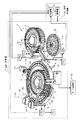
図2は、分析部24の構成を示した斜視図である。この分析部24は、標準試料や被検試料等の試料を収容する試料容器17と、試料容器17を保持するサンプルディスク5とを備えている。また、試料に含まれる検査項目の成分と反応する成分を含有する1試薬系及び2試薬系の第1試薬を収容する試薬容器6と、試薬容器6を格納する試薬庫1と、試薬庫1に格納された試薬容器6を回動可能に保持する試薬ラック1aとを備えている。また、2試薬系の第1試薬と対をなす第2試薬を収容する試薬容器7と、試薬容器7を格納する試薬庫2と、試薬庫2に格納された試薬容器7を回動可能に保持する試薬ラック2aとを備えている。また、円周上に配置された複数の反応容器3と、反応容器3を回転可能に保持する反応ディスク4とを備えている。
FIG. 2 is a perspective view showing the configuration of the
また、サンプルディスク5に保持された試料容器17内の試料を吸引して反応容器3内へ吐出する分注を行うサンプル分注プローブ16と、サンプル分注プローブ16に試料の吸引及び吐出を行わせるサンプル分注ポンプ16aと、サンプル分注プローブ16を移動可能に保持するサンプル分注アーム10とを備えている。また、サンプルディスク5に保持された試料容器17内の試料の液面をこの液面とサンプル分注プローブ16との接触により検出する試料検出器16bと、サンプル分注プローブ16を洗浄する洗浄槽70とを備えている。
Further, the
また、試薬ラック1aに保持された試薬容器6内の第1試薬を吸引して試料が分注された反応容器3内に吐出する分注を行う第1試薬分注プローブ14と、第1試薬分注プローブ14に第1試薬の吸引及び吐出を行わせる第1試薬分注ポンプ14aと、第1試薬分注プローブ14を移動可能に保持する第1試薬分注アーム8とを備えている。また、試薬ラック1aに保持された試薬容器6内の第1試薬の液面をこの液面と第1試薬分注プローブ14との接触により検出する第1試薬検出器14bと、第1試薬分注プローブ14を洗浄する洗浄槽80とを備えている。
In addition, a first
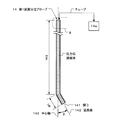
図3は、第1試薬分注プローブ14の構成を示した断面図である。この第1試薬分注プローブ14は管状を成し、一端に第1試薬を吸引して吐出する開口141を有し、他端部が第1試薬分注アーム8に保持される。そして、一端を含む一端部内に斜め下方に傾斜した開口141に通ずる第1の流路W1が形成されている。また、一端部以外の内部には、第1の流路W1に連なる第2の流路W2が上下方向に形成されている。そして、第1の流路W1を延長したその流路の中心を通る延長線142が、第2の流路W2の中心を通る中心軸143に対して角度θ(θ<90°)傾斜している。
FIG. 3 is a cross-sectional view showing the configuration of the first
また、他端がチューブを介して第1試薬分注ポンプ14aに連通し、第1及び第2の流路W1,W2及びチューブ内に第1試薬分注ポンプ14aからの吸引及び吐出動作による圧力を伝達する純水等の圧力伝達媒体を保持している。そして、第1試薬分注ポンプ14aの吸引動作により、試薬ラック1aに保持された試薬容器6内の第1試薬を吸引する。また、第1試薬分注ポンプ14aの吐出動作により、吸引した第1試薬を吐出する。
Further, the other end communicates with the first
図2に示した分析部24は、反応容器3に分注された試料と第1試薬の混合液を撹拌する第1撹拌子18と、第1撹拌子18を移動可能に保持する第1撹拌アーム20と、第1撹拌子18を洗浄する洗浄槽18aとを備えている。
The
また、試薬ラック2aに保持された試薬容器7内の第2試薬を吸引して第1試薬が分注された反応容器3内に吐出する分注を行う第2試薬分注プローブ15と、第2試薬分注プローブ15に第2試薬の吸引及び吐出を行わせる第2試薬分注ポンプ15aと、第2試薬分注プローブ15を移動可能に保持する第2試薬分注アーム9とを備えている。また、試薬ラック2aに保持された試薬容器7内の第2試薬の液面をこの液面と第2試薬分注プローブ15との接触により検出する第2試薬検出器15bと、第2試薬分注プローブ15を洗浄する洗浄槽90とを備えている。
Also, a second
また、反応容器3に分注された試料、第1試薬、及び第2試薬の混合液を撹拌する第2撹拌子19と、第2撹拌子19を回動及び上下移動可能に保持する第2撹拌アーム21と、第2撹拌子19を洗浄する洗浄槽19aとを備えている。また、反応容器3内の混合液に光を照射して光学的に測定する測光部13と、測光部13で測定を終了した反応容器3内を洗浄する反応容器洗浄ユニット12とを備えている。
The
そして、測光部13は、回転移動して光路を横切る反応容器3に光を照射し、この照射により反応容器3内の試料及び第1試薬の混合液や、試料、第1試薬、及び第2試薬の混合液を透過した光を検査項目の波長毎に検出する。そして、検出した検出信号を処理してデジタル信号で表される標準データや被検データを生成し、生成した標準データや被検データをデータ処理部30に出力する。
Then, the
分析制御部25は、分析部24の各分析ユニットを駆動する機構を有する機構部26と、機構部26の各機構を制御する制御部27とを備えている。そして、機構部26は、サンプルディスク5、試薬ラック1a、及び試薬ラック2aを夫々回動する機構、並びに反応ディスク4を回転する機構を備えている。また、サンプル分注アーム10、第1試薬分注アーム8、第2試薬分注アーム9、第1撹拌アーム20、及び第2撹拌アーム21を夫々回動及び上下移動する機構を備えている。また、サンプル分注ポンプ16a、第1試薬分注ポンプ14a、及び第2試薬分注ポンプ15aを夫々吸引及び吐出駆動する機構、並びに反応容器洗浄ユニット12を上下移動する機構を備えている。
The analysis control unit 25 includes a
制御部27は、機構部26のサンプルディスク5、試薬ラック1a、試薬ラック2a、反応ディスク4、サンプル分注アーム10、第1試薬分注アーム8、第2試薬分注アーム9、サンプル分注ポンプ16a、第1試薬分注ポンプ14a、第2試薬分注ポンプ15a、反応容器洗浄ユニット12等の各分析ユニットを駆動する機構を制御する制御回路を備えている。そして、各第1及び第2試薬分注アーム8,9の機構を制御して、各第1及び第2試薬分注プローブ14,15を移動させる。
The
制御部27における第1試薬分注アーム8の制御回路は、第1試薬分注アーム8を回動する回動機構及びこの回動機構及び第1試薬分注アーム8を上下方向に移動する上下移動機構を制御する。そして、第1試薬分注プローブ14を、回動機構により上死点の高さで試薬庫1、反応ディスク4、及び洗浄槽80の各上停止位置へ移動させる。また、上下移動機構に下移動駆動パルスを供給して各上停止位置から下に移動させ、様々な位置で停止させる。
The control circuit of the first reagent dispensing arm 8 in the
ここで、第1試薬の分注における吸引では、第1試薬分注プローブ14を試薬庫1の上停止位置から下へ移動させる。そして、第1試薬検出器14bからの検出信号に基づいて、試薬容器6内の第1試薬の液面が第1試薬検出器14bにより検出される位置から、その第1試薬の吸引が可能な所定の距離下方へ移動させた第1試薬吸引位置で停止させる。
Here, in the aspiration in dispensing the first reagent, the first
また、第1試薬の吐出では、第1試薬分注プローブ14を反応ディスク4の上停止位置から下へ移動して、第1試薬分注プローブ14の一端を含む一部を反応容器3から離間して反応容器3内へ進入させた後、予め検査項目毎に設定された反応容器3内に吐出させる試料の量及び第1試薬の量に基づいて、第1試薬分注プローブ14を停止させる停止位置を可変する。
In discharging the first reagent, the first
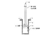
そして、図4に示すように、第1試薬分注プローブ14における第1の流路W1の延長線142が反応容器3内の底面以外の内面に交わり、交わる内面の位置が予め設定された量の試料及び第1試薬からなる混合液の液面Sの高さとなる混合液上方の第1試薬吐出位置で停止させる。この第1試薬吐出位置で停止した第1試薬分注プローブ14により、反応容器3内面に向けて第1試薬が吐出され、吐出された第1試薬は反応容器3内面の混合液の液面Sと延長線142の交点Pに当たった後、反応容器3内面を伝わって降下する。
Then, as shown in FIG. 4, the extension line 142 of the first flow path W1 in the first
なお、第1試薬分注プローブ14を第1試薬吐出位置よりも下方であり、且つ反応容器3内に吐出された試料よりも上方の位置に停止させた後、第1試薬を吐出させながら、反応容器3内の試料と吐出された第1試薬の混合液の液面の上方に一端が位置するように第1試薬分注プローブ14を第1試薬吐出位置まで上に移動させるように実施してもよい。
In addition, after stopping the first
制御部27の第2試薬分注アーム9の制御回路は、第2試薬分注アーム9を回動する回動機構及びこの回動機構及び第2試薬分注アーム9を上下方向に移動する上下移動機構を制御する。そして、第2試薬分注プローブ15を、回動機構により上死点の高さで試薬庫2、反応ディスク4、及び洗浄槽90の各上停止位置へ移動させる。また、下移動駆動パルスを供給して上下移動機構により各上停止位置から下に移動させ、様々な位置で停止させる。
The control circuit of the second reagent dispensing arm 9 of the
ここで、第2試薬の分注における吸引では、第2試薬分注プローブ15を試薬庫2の上停止位置から下へ移動させる。そして、第2試薬検出器15bからの検出信号に基づいて、試薬容器7内の第2試薬の液面が第2試薬検出器15bにより検出される位置から、その第2試薬の吸引が可能な所定の距離下方へ移動させた第2試薬吸引位置で停止させる。また、第2試薬の吐出では、反応ディスク4の上停止位置で停止させ、停止させた位置で反応容器3内への第2試薬の吐出が行われる。
Here, in the suction in dispensing the second reagent, the second
図1に示したデータ処理部30は、分析部24の測光部13から出力された標準データや被検データを処理して各検査項目の検量データや分析データを生成する演算部31と、演算部31で生成された標準データや分析データを保存するデータ記憶部32とを備えている。
The
演算部31は、測光部13から出力された標準データ及びこの標準データの標準試料に対して予め設定された標準値から、標準値と標準データの関係を表す検量データを生成し、生成した検量データを出力部40に出力すると共にデータ記憶部32に保存する。
The
また、測光部13から出力された被検データに対応する検査項目の検量データをデータ記憶部32から読み出す。そして、読み出した検量データを用いて測光部13より出力された被検データから、濃度値や活性値として表される分析データを生成する。そして、生成した分析データを出力部40に出力すると共にデータ記憶部32に保存する。
Further, the calibration data of the inspection item corresponding to the test data output from the
データ記憶部32は、ハードディスク等のメモリデバイスを備え、演算部31から出力された検量データを検査項目毎に保存する。また、演算部31から出力された各検査項目の分析データを被検試料毎に保存する。
The data storage unit 32 includes a memory device such as a hard disk, and stores the calibration data output from the
出力部40は、データ処理部30の演算部31から出力された検量データや分析データを印刷出力する印刷部41及び表示出力する表示部42を備えている。そして、印刷部41は、プリンタなどを備え、演算部31から出力された検量データや分析データを予め設定されたフォーマットに従って、プリンタ用紙などに印刷する。
The output unit 40 includes a printing unit 41 that prints out calibration data and analysis data output from the
表示部42は、CRTや液晶パネルなどのモニタを備え、演算部31から出力された検量データや分析データを表示する。また、各検査項目を分析するために反応容器3内に吐出させる試料の量、第1試薬の量、及び第2試薬の量等の分析パラメータを設定するための分析パラメータ設定画面、及びこの分析パラメータ設定画面で設定された検査項目の分析に用いる試薬の情報を設定するための試薬情報設定画面を表示する。また、被検試料毎にこの被検試料を識別する氏名やID等の識別情報及び分析パラメータ設定画面で設定された検査項目の中から検査対象となる検査項目を選択して設定するための検査項目設定画面を表示する。
The
操作部50は、キーボード、マウス、ボタン、タッチキーパネルなどの入力デバイスを備え、検査項目毎の分析パラメータ、試薬情報、被検試料の識別情報及び検査項目、被検試料毎に識別情報及び検査対象となる検査項目を設定するための入力操作を行う。
The
システム制御部60は、CPU及び記憶回路を備え、操作部50からの操作により入力された各検査項目の分析パラメータの情報、試薬情報、被検試料毎の識別情報及び検査項目の情報等の入力情報を記憶回路に記憶した後、これらの入力情報に基づいて、分析制御部25、データ処理部30、及び出力部40を統括してシステム全体を制御する。
The
以下、図1乃至図8を参照して、分析部24における第1及び第2試薬の分注工程について説明する。そして、図5は、第1試薬を分注する第1試薬分注工程を示すフローチャートである。また、図6は、第1試薬の分注における第1試薬分注プローブ14の各停止位置を示す図である。また、図7は、第2試薬を分注する第2試薬分注工程を示すフローチャートである。また、図8は、第2試薬の分注における第2試薬分注プローブ15の各停止位置を示す図である。
Hereinafter, the dispensing process of the first and second reagents in the
先ず、第1試薬を分注する第1試薬分注工程について説明する。
図5は、第1試薬分注工程を示したフローチャートである。この第1試薬分注工程S10では、第1試薬分注プローブ14は、ホームポジションである例えば洗浄槽80の上停止位置から移動して、試薬庫1の上停止位置で停止する(ステップS11)。
First, the first reagent dispensing process for dispensing the first reagent will be described.
FIG. 5 is a flowchart showing the first reagent dispensing step. In the first reagent dispensing step S10, the first
試薬庫1の上停止位置で停止した後、第1試薬分注プローブ14は、所定量の空気を吸引する(ステップS12)。
After stopping at the upper stop position of the reagent storage 1, the first
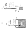
空気を吸引した後、第1試薬分注プローブ14は、試薬庫1の上停止位置から下へ移動して、図6(a)に示すように、試薬ラック1aに保持された試薬容器6内の第1試薬の液面が第1試薬検出器14bにより検出される位置から所定の距離下方へ移動した第1試薬吸引位置で停止する(ステップS13)。
After the air is aspirated, the first
第1試薬吸引位置で停止した後、第1試薬分注プローブ14は、表示部42の分析パラメータ設定画面で設定された第1試薬の量の情報に基づいて、試薬容器6からダミーの第1試薬及び分析用の第1試薬を吸引する(ステップS14)。
After stopping at the first reagent aspirating position, the first
ここで、第1試薬分注ポンプ14aの吸引動作により圧力伝達媒体を流動させて第1試薬を吸引したとき、第1試薬分注プローブ14内面に残存する圧力伝達媒体の第1試薬への混入や第1試薬の圧力伝達媒体への拡散により、吸引した第1試薬が希釈される問題がある。この問題を避けるために、所定量の空気及び分析に使用しないダミーの第1試薬を吸引する。このダミー第1試薬の吸引に引き続き、各分析項目の分析に使用する分析用の第1試薬を吸引する。
Here, when the first reagent is sucked by flowing the pressure transmission medium by the suction operation of the first
第1試薬を吸引した後、第1試薬分注プローブ14は、第1試薬吸引位置から上へ移動して試薬庫1の上停止位置で停止する。次いで、試薬庫1の上停止位置から移動して、図6(b)に示すように、反応ディスク4の上停止位置で停止する(ステップS15)。
After aspirating the first reagent, the first
反応ディスク4の上停止位置で停止した後、第1試薬分注プローブ14は、表示部42の分析パラメータ設定画面で設定された試料の量及び第1試薬の量の情報に基づいて、上停止位置から下へ移動して、図6(c)に示すように、一端を含む一部が反応容器3から離間して反応容器3内へ進入した第1試薬吐出位置で停止する(ステップS16)。
After stopping at the upper stop position of the
第1試薬吐出位置で停止した後、第1試薬分注プローブ14は、図6(c)に示すように、試料が分注された反応容器3内面の交点Pに向けて分析用の第1試薬を吐出する(ステップS17)。
After stopping at the first reagent discharge position, as shown in FIG. 6 (c), the first
このように、第1試薬分注プローブ14を第1試薬吐出位置で停止させることにより、第1試薬を反応容器3内面の交点Pに向けて吐出させることができる。これにより、吐出された第1試薬が反応容器3内面における混合液の液面S以下の面を伝わって降下するため、吐出された第1試薬のすべてを、測定に関与する第1試薬として用いることができる。また、第1試薬分注プローブ14の一端部が混合液に触れて汚染されるのを防ぐことができる。
Thus, by stopping the first
また、第1試薬分注プローブ14から反応容器3内面の交点Pに向けて吐出された第1試薬が反応容器3内面を伝わって降下することにより、反応容器3内の試料と衝突するときの衝撃を低減することができるため、試料の一部が反応容器3内の測定に関与しない位置及び反応容器3外へ飛散するのを抑制することができる。
Further, when the first reagent discharged from the first
更に、第1試薬分注プローブ14から交点Pに向けて吐出された第1試薬が反応容器3内面を伝わって降下することにより、降下して反応容器3内に貯留された第1試薬と衝突するときの衝撃を低減することができるため、反応容器3内に吐出された第1試薬の泡立ちを抑制することができる。これにより、試料の一部が巻き込まれて泡に保持されるのを防ぐことが可能となり、第1撹拌子18で試料と第1試薬を均一に撹拌することができる。また、泡の上方から第2試薬を吐出するのを防ぐことが可能となり、第2撹拌子19で試料、第1試薬、及び第2試薬を均一に撹拌することができる。
Furthermore, when the first reagent discharged from the first
分析用第1試薬を吐出した後、第1試薬分注プローブ14は、第1試薬吐出位置から上方へ移動して反応ディスク4の上停止位置で停止する。次いで、反応ディスク4の上停止位置から移動して洗浄槽80の上停止位置で停止する。洗浄槽80の上停止位置で停止した後、洗浄槽80で第1試薬分注プローブ14の第1試薬に接触した内外面の洗浄を行う(ステップS18)。
After discharging the first reagent for analysis, the first
洗浄が行われた後、第1試薬分注プローブ14は、次の第1試薬の分注に備えて、ホームポジションで停止する(ステップS19)。
After the cleaning is performed, the first
次に、第2試薬を分注する第2試薬分注工程について説明する。
図7は、第2試薬を分注する第2試薬分注工程を示したフローチャートである。この第2試薬分注工程S30では、第2試薬分注プローブ15は、ホームポジションである洗浄槽90の上停止位置から移動して、試薬庫2の上停止位置で停止する(ステップS31)。
Next, the second reagent dispensing step for dispensing the second reagent will be described.
FIG. 7 is a flowchart showing a second reagent dispensing process for dispensing the second reagent. In the second reagent dispensing step S30, the second
試薬庫2の上停止位置で停止した後、第2試薬分注プローブ15は、所定量の空気を吸引する(ステップS32)。
After stopping at the upper stop position of the reagent storage 2, the second
空気を吸引した後、第2試薬分注プローブ15は、試薬庫2の上停止位置から下へ移動して、図8(a)に示すように、試薬ラック2aに保持された試薬容器7内の第2試薬の液面が第2試薬検出器15bにより検出される位置から所定の距離下方へ移動した第2試薬吸引位置で停止する(ステップS33)。
After the air is aspirated, the second
第2試薬吸引位置で停止した後、第2試薬分注プローブ15は、試薬容器7内のダミーの第2試薬及び分析用の第2試薬を吸引する(ステップS34)。
After stopping at the second reagent suction position, the second
第2試薬を吸引した後、第2試薬分注プローブ15は、第2試薬吸引位置から上へ移動して試薬庫2の上停止位置で停止する。次いで、試薬庫2の上停止位置から移動して、図8(b)に示すように、反応ディスク4の上停止位置で停止する(ステップS35)。
After aspirating the second reagent, the second
反応ディスク4の上停止位置で停止した後、第2試薬分注プローブ15は、反応ディスク4の上停止位置を第2試薬吐出位置として、上下方向に直線状に形成された流路の一端から、試料及び第1試薬が分注された反応容器3内に分析用の第2試薬を吐出する(ステップS36)。
After stopping at the upper stop position of the
分析用第2試薬を吐出した後、第2試薬分注プローブ15は、反応ディスク4の上停止位置から移動して、洗浄槽90の上停止位置で停止する。洗浄槽90の上停止位置で停止した後、洗浄槽90で第2試薬分注プローブ15の第2試薬に接触した内外面の洗浄を行う(ステップS37)。
After discharging the second reagent for analysis, the second
洗浄が行われた後、第2試薬分注プローブ15は、次の第2試薬の分注に備えて、ホームポジションで停止する(ステップS38)。
After the cleaning is performed, the second
なお、第2試薬を吸引及び吐出する一端部の内部に斜め下方に傾斜した第1の流路が形成され、一端部以外の内部に第1の流路に連なる上下方向に第2の流路が形成された第1試薬分注プローブ14と同様に構成される第2試薬分注プローブに置き換える。そして、その置き換えた第2試薬分注プローブを、第1試薬分注プローブ14と同様に移動して、その第2試薬分注プローブの第1の流路の延長線が反応容器3内の底面以外の内面に交わり、交わる内面の位置が反応容器3内に吐出される試料、第1試薬、及び第2試薬の混合液の液面の高さとなる混合液上方の第2試薬吐出位置で停止させるように実施してもよい。
In addition, a first channel that is inclined obliquely downward is formed inside the one end portion for sucking and discharging the second reagent, and the second channel in the vertical direction that is continuous with the first channel inside the other end portion. Is replaced with a second reagent dispensing probe configured in the same manner as the first
以上述べた本発明の実施例によれば、第1試薬の分注では、一端を含む一端部内に斜め下方に傾斜した開口141に通ずる第1の流路W1が形成された第1試薬分注プローブ14を移動して、一端を含む一部が反応容器3から離間して反応容器3内へ進入した第1試薬吐出位置で停止させることにより、第1試薬を反応容器3内面の交点Pに向けて吐出させることができる。これにより、吐出された第1試薬が反応容器3内面における混合液の液面S以下の面を伝わって降下するため、吐出された第1試薬のすべてを、測定に関与する第1試薬として用いることができる。また、第1試薬分注プローブ14の一端部が混合液に触れて汚染されるのを防ぐことができる。
According to the embodiment of the present invention described above, in the first reagent dispensing, the first reagent dispensing in which the first flow path W1 leading to the opening 141 inclined obliquely downward is formed in the one end including the one end. By moving the
また、第1試薬分注プローブ14から反応容器3内面の交点Pに向けて吐出された第1試薬が反応容器3内面を伝わって降下することにより、反応容器3内の試料と衝突するときの衝撃を低減することができるため、試料の一部が反応容器3内の測定に関与しない位置及び反応容器3外へ飛散するのを抑制することができる。
Further, when the first reagent discharged from the first
更に、第1試薬分注プローブ14から交点Pに向けて吐出された第1試薬が反応容器3内面を伝わって降下することにより、降下して反応容器3内に貯留された第1試薬と衝突するときの衝撃を低減することができるため、反応容器3内に吐出された第1試薬の泡立ちを抑制することができる。これにより、試料の一部が巻き込まれて泡に保持されるのを防ぐことが可能となり、第1撹拌子18で試料と第1試薬を均一に撹拌することができる。また、泡の上方から第2試薬を吐出するのを防ぐことが可能となり、第2撹拌子19で試料、第1試薬、及び第2試薬を均一に撹拌することができる。
Furthermore, when the first reagent discharged from the first
以上により、分析データの向上を図ることができる。 As described above, analysis data can be improved.
P 交点
W1 第1の流路
3 反応容器
4 反応ディスク
14 第1試薬分注プローブ
142 延長線
P intersection point W1
Claims (4)
前記試薬を吸引して前記反応容器内に吐出する開口を一端に有し、この一端を含む一端部内に斜め下方に傾斜した前記開口に通ずる流路が形成された試薬分注プローブと、
前記試薬分注プローブを前記試料が分注された前記反応容器内へ進入させる際は、前記一端を前記反応容器から離間させ且つ前記流路の延長線が当該反応容器内における底面以外の内面に交わる位置で停止させ、この停止位置から前記試薬分注プローブにより前記内面に向けて前記試薬を吐出させる分析制御手段とを
備えたことを特徴とする自動分析装置。 In an automatic analyzer that dispenses a sample and a reagent into a reaction vessel and measures the mixture,
Has an opening for discharging into the reaction vessel by sucking the reagent on one end, and the reagent dispensing probe flow path is formed leading to said opening which is inclined obliquely downward in one end portion including the one end,
When to enter the reagent dispensing probe into the sample is dispensed inside the reaction vessel, the one end to the inner surface other than the bottom surface in the reaction is separated from the container and the extension line of the channel is the reaction vessel An automatic analyzer comprising: an analysis control unit that stops at a crossing position and discharges the reagent from the stop position toward the inner surface by the reagent dispensing probe .
前記分析制御手段は、前記設定手段により設定された前記試料及び前記試薬の量に基づいて前記停止位置を可変するようにしたことを特徴とする請求項1又は請求項2に記載の自動分析装置。 Setting means for setting the amount of the sample to be discharged into the reaction container and the amount of the reagent;
3. The automatic analyzer according to claim 1, wherein the analysis control unit is configured to change the stop position based on the amount of the sample and the reagent set by the setting unit. 4. .
前記試薬分注プローブは、前記第1試薬を分注する第1試薬分注プローブ、又は前記第1試薬を分注する第1試薬分注プローブ及び前記第1試薬が分注された前記反応容器内に前記第2試薬を分注する第2試薬分注プローブからなることを特徴とする請求項1乃至請求項3のいずれかに記載の自動分析装置。 The reagent is a first reagent in a two-reagent system and a second reagent paired with the first reagent,
The reagent dispensing probe is a first reagent dispensing probe for dispensing the first reagent, or a first reagent dispensing probe for dispensing the first reagent and the reaction container into which the first reagent has been dispensed. The automatic analyzer according to any one of claims 1 to 3 , further comprising a second reagent dispensing probe for dispensing the second reagent .
Priority Applications (1)
| Application Number | Priority Date | Filing Date | Title |
|---|---|---|---|
| JP2010058474A JP5571982B2 (en) | 2010-03-15 | 2010-03-15 | Automatic analyzer |
Applications Claiming Priority (1)
| Application Number | Priority Date | Filing Date | Title |
|---|---|---|---|
| JP2010058474A JP5571982B2 (en) | 2010-03-15 | 2010-03-15 | Automatic analyzer |
Related Child Applications (1)
| Application Number | Title | Priority Date | Filing Date |
|---|---|---|---|
| JP2013218645A Division JP2014041144A (en) | 2013-10-21 | 2013-10-21 | Automatic analyzer |
Publications (2)
| Publication Number | Publication Date |
|---|---|
| JP2011191216A JP2011191216A (en) | 2011-09-29 |
| JP5571982B2 true JP5571982B2 (en) | 2014-08-13 |
Family
ID=44796302
Family Applications (1)
| Application Number | Title | Priority Date | Filing Date |
|---|---|---|---|
| JP2010058474A Active JP5571982B2 (en) | 2010-03-15 | 2010-03-15 | Automatic analyzer |
Country Status (1)
| Country | Link |
|---|---|
| JP (1) | JP5571982B2 (en) |
Cited By (1)
| Publication number | Priority date | Publication date | Assignee | Title |
|---|---|---|---|---|
| JP2014041144A (en) * | 2013-10-21 | 2014-03-06 | Toshiba Corp | Automatic analyzer |
Families Citing this family (1)
| Publication number | Priority date | Publication date | Assignee | Title |
|---|---|---|---|---|
| JP6351950B2 (en) * | 2013-10-22 | 2018-07-04 | キヤノンメディカルシステムズ株式会社 | Automatic analyzer and dispenser |
Family Cites Families (12)
| Publication number | Priority date | Publication date | Assignee | Title |
|---|---|---|---|---|
| JPS63265169A (en) * | 1987-04-23 | 1988-11-01 | Toshiba Corp | Reaction-tube washing apparatus |
| JPH0244257A (en) * | 1988-08-04 | 1990-02-14 | Yasunobu Tsukioka | Dispencing/suction apparatus and method for sucking and discharging chemical liquid/washing water by the apparatus |
| JP3567187B2 (en) * | 1995-02-23 | 2004-09-22 | アークレイ株式会社 | Stirring device for sample liquid, etc. |
| FR2767583B1 (en) * | 1997-08-20 | 1999-10-22 | Junior Instruments | DEVICE FOR THE COLLECTION AND / OR INJECTION INSIDE A MOUTH SAMPLE TUBE |
| US6413428B1 (en) * | 1999-09-16 | 2002-07-02 | Berger Instruments, Inc. | Apparatus and method for preparative supercritical fluid chromatography |
| JP4175916B2 (en) * | 2003-02-21 | 2008-11-05 | 株式会社東芝 | Automatic analyzer |
| JP4166621B2 (en) * | 2003-05-16 | 2008-10-15 | オリンパス株式会社 | Automatic analyzer |
| JP2005164523A (en) * | 2003-12-05 | 2005-06-23 | Sysmex Corp | Sample suction and dispensing apparatus, and sample-producing apparatus with the same |
| JP4783170B2 (en) * | 2006-02-13 | 2011-09-28 | 株式会社東芝 | Automatic analyzer |
| JP4891749B2 (en) * | 2006-12-12 | 2012-03-07 | 株式会社東芝 | Automatic analyzer |
| JP2008164480A (en) * | 2006-12-28 | 2008-07-17 | Rohm Co Ltd | Fluid injection method, and method for manufacturing liquid reagent built-in type microchip |
| JP2009145143A (en) * | 2007-12-13 | 2009-07-02 | Hitachi High-Technologies Corp | Autoanalyzer |
-
2010
- 2010-03-15 JP JP2010058474A patent/JP5571982B2/en active Active
Cited By (1)
| Publication number | Priority date | Publication date | Assignee | Title |
|---|---|---|---|---|
| JP2014041144A (en) * | 2013-10-21 | 2014-03-06 | Toshiba Corp | Automatic analyzer |
Also Published As
| Publication number | Publication date |
|---|---|
| JP2011191216A (en) | 2011-09-29 |
Similar Documents
| Publication | Publication Date | Title |
|---|---|---|
| US9086395B2 (en) | Automatic analysis apparatus | |
| JP4812352B2 (en) | Automatic analyzer and its dispensing method | |
| JP6068536B2 (en) | Automatic analyzer | |
| JP2012083369A (en) | Automated analyzer and probe up-and-down method | |
| US9513305B2 (en) | Multiple cleaning stations for a dispensing probe | |
| JP5305794B2 (en) | Automatic analyzer | |
| JP2011232249A (en) | Automatic analyzing apparatus | |
| JP5571982B2 (en) | Automatic analyzer | |
| JP4871025B2 (en) | Automatic analyzer and its sample dispensing method | |
| JP6121743B2 (en) | Automatic analyzer | |
| JP5606843B2 (en) | Automatic analyzer | |
| JP2016206112A (en) | Automatic analyzer | |
| JP6193600B2 (en) | Automatic analyzer | |
| JP2011227092A (en) | Automatic analyzing apparatus | |
| JP5883214B2 (en) | Automatic analyzer | |
| JP2014041144A (en) | Automatic analyzer | |
| JP2014066730A (en) | Automatic analyzing apparatus | |
| JP5931540B2 (en) | Automatic analyzer and inspection system | |
| JP5305988B2 (en) | Automatic analyzer | |
| JP5808473B2 (en) | Automatic analyzer | |
| JP6537895B2 (en) | Automatic analyzer | |
| JP2011257248A (en) | Automatic analyzer | |
| JP6049671B2 (en) | Automatic analyzer and its dispensing probe | |
| JP2021165652A (en) | Automatic analyzer | |
| JP5180710B2 (en) | Automatic analyzer |
Legal Events
| Date | Code | Title | Description |
|---|---|---|---|
| RD02 | Notification of acceptance of power of attorney |
Free format text: JAPANESE INTERMEDIATE CODE: A7422 Effective date: 20111128 |
|
| RD04 | Notification of resignation of power of attorney |
Free format text: JAPANESE INTERMEDIATE CODE: A7424 Effective date: 20111206 |
|
| A621 | Written request for application examination |
Free format text: JAPANESE INTERMEDIATE CODE: A621 Effective date: 20130226 |
|
| A977 | Report on retrieval |
Free format text: JAPANESE INTERMEDIATE CODE: A971007 Effective date: 20130814 |
|
| A131 | Notification of reasons for refusal |
Free format text: JAPANESE INTERMEDIATE CODE: A131 Effective date: 20130820 |
|
| A521 | Written amendment |
Free format text: JAPANESE INTERMEDIATE CODE: A523 Effective date: 20131021 |
|
| TRDD | Decision of grant or rejection written | ||
| A01 | Written decision to grant a patent or to grant a registration (utility model) |
Free format text: JAPANESE INTERMEDIATE CODE: A01 Effective date: 20140530 |
|
| A61 | First payment of annual fees (during grant procedure) |
Free format text: JAPANESE INTERMEDIATE CODE: A61 Effective date: 20140627 |
|
| R150 | Certificate of patent or registration of utility model |
Ref document number: 5571982 Country of ref document: JP Free format text: JAPANESE INTERMEDIATE CODE: R150 |
|
| S111 | Request for change of ownership or part of ownership |
Free format text: JAPANESE INTERMEDIATE CODE: R313117 |
|
| R350 | Written notification of registration of transfer |
Free format text: JAPANESE INTERMEDIATE CODE: R350 |
|
| S533 | Written request for registration of change of name |
Free format text: JAPANESE INTERMEDIATE CODE: R313533 |
|
| R350 | Written notification of registration of transfer |
Free format text: JAPANESE INTERMEDIATE CODE: R350 |