JP5561496B2 - Flow control valve and its assembly method - Google Patents
Flow control valve and its assembly method Download PDFInfo
- Publication number
- JP5561496B2 JP5561496B2 JP2011534847A JP2011534847A JP5561496B2 JP 5561496 B2 JP5561496 B2 JP 5561496B2 JP 2011534847 A JP2011534847 A JP 2011534847A JP 2011534847 A JP2011534847 A JP 2011534847A JP 5561496 B2 JP5561496 B2 JP 5561496B2
- Authority
- JP
- Japan
- Prior art keywords
- control valve
- flow control
- sub
- valve
- flow
- Prior art date
- Legal status (The legal status is an assumption and is not a legal conclusion. Google has not performed a legal analysis and makes no representation as to the accuracy of the status listed.)
- Active
Links
- 238000000034 method Methods 0.000 title claims description 10
- 239000012530 fluid Substances 0.000 claims description 47
- 238000004891 communication Methods 0.000 claims description 35
- 230000002093 peripheral effect Effects 0.000 claims description 19
- 238000000465 moulding Methods 0.000 claims description 7
- 230000007423 decrease Effects 0.000 claims description 3
- 238000002788 crimping Methods 0.000 claims description 2
- 238000005452 bending Methods 0.000 claims 1
- 238000006073 displacement reaction Methods 0.000 description 7
- 230000001276 controlling effect Effects 0.000 description 6
- 238000004519 manufacturing process Methods 0.000 description 4
- 238000012856 packing Methods 0.000 description 4
- 125000006850 spacer group Chemical group 0.000 description 4
- 238000005520 cutting process Methods 0.000 description 3
- 239000000463 material Substances 0.000 description 3
- 238000012545 processing Methods 0.000 description 2
- 238000013459 approach Methods 0.000 description 1
- 230000003247 decreasing effect Effects 0.000 description 1
- 230000000694 effects Effects 0.000 description 1
- 239000013013 elastic material Substances 0.000 description 1
- 238000003780 insertion Methods 0.000 description 1
- 230000037431 insertion Effects 0.000 description 1
- 239000002184 metal Substances 0.000 description 1
- 239000007769 metal material Substances 0.000 description 1
- 230000001105 regulatory effect Effects 0.000 description 1
- 239000011347 resin Substances 0.000 description 1
- 229920005989 resin Polymers 0.000 description 1
Images


Classifications
-
- B—PERFORMING OPERATIONS; TRANSPORTING
- B65—CONVEYING; PACKING; STORING; HANDLING THIN OR FILAMENTARY MATERIAL
- B65D—CONTAINERS FOR STORAGE OR TRANSPORT OF ARTICLES OR MATERIALS, e.g. BAGS, BARRELS, BOTTLES, BOXES, CANS, CARTONS, CRATES, DRUMS, JARS, TANKS, HOPPERS, FORWARDING CONTAINERS; ACCESSORIES, CLOSURES, OR FITTINGS THEREFOR; PACKAGING ELEMENTS; PACKAGES
- B65D83/00—Containers or packages with special means for dispensing contents
- B65D83/14—Containers or packages with special means for dispensing contents for delivery of liquid or semi-liquid contents by internal gaseous pressure, i.e. aerosol containers comprising propellant for a product delivered by a propellant
-
- F—MECHANICAL ENGINEERING; LIGHTING; HEATING; WEAPONS; BLASTING
- F16—ENGINEERING ELEMENTS AND UNITS; GENERAL MEASURES FOR PRODUCING AND MAINTAINING EFFECTIVE FUNCTIONING OF MACHINES OR INSTALLATIONS; THERMAL INSULATION IN GENERAL
- F16K—VALVES; TAPS; COCKS; ACTUATING-FLOATS; DEVICES FOR VENTING OR AERATING
- F16K1/00—Lift valves or globe valves, i.e. cut-off apparatus with closure members having at least a component of their opening and closing motion perpendicular to the closing faces
- F16K1/02—Lift valves or globe valves, i.e. cut-off apparatus with closure members having at least a component of their opening and closing motion perpendicular to the closing faces with screw-spindle
- F16K1/04—Lift valves or globe valves, i.e. cut-off apparatus with closure members having at least a component of their opening and closing motion perpendicular to the closing faces with screw-spindle with a cut-off member rigid with the spindle, e.g. main valves
-
- F—MECHANICAL ENGINEERING; LIGHTING; HEATING; WEAPONS; BLASTING
- F16—ENGINEERING ELEMENTS AND UNITS; GENERAL MEASURES FOR PRODUCING AND MAINTAINING EFFECTIVE FUNCTIONING OF MACHINES OR INSTALLATIONS; THERMAL INSULATION IN GENERAL
- F16K—VALVES; TAPS; COCKS; ACTUATING-FLOATS; DEVICES FOR VENTING OR AERATING
- F16K1/00—Lift valves or globe valves, i.e. cut-off apparatus with closure members having at least a component of their opening and closing motion perpendicular to the closing faces
- F16K1/32—Details
- F16K1/34—Cutting-off parts, e.g. valve members, seats
- F16K1/36—Valve members
- F16K1/38—Valve members of conical shape
-
- F—MECHANICAL ENGINEERING; LIGHTING; HEATING; WEAPONS; BLASTING
- F16—ENGINEERING ELEMENTS AND UNITS; GENERAL MEASURES FOR PRODUCING AND MAINTAINING EFFECTIVE FUNCTIONING OF MACHINES OR INSTALLATIONS; THERMAL INSULATION IN GENERAL
- F16K—VALVES; TAPS; COCKS; ACTUATING-FLOATS; DEVICES FOR VENTING OR AERATING
- F16K1/00—Lift valves or globe valves, i.e. cut-off apparatus with closure members having at least a component of their opening and closing motion perpendicular to the closing faces
- F16K1/32—Details
- F16K1/34—Cutting-off parts, e.g. valve members, seats
- F16K1/42—Valve seats
-
- F—MECHANICAL ENGINEERING; LIGHTING; HEATING; WEAPONS; BLASTING
- F16—ENGINEERING ELEMENTS AND UNITS; GENERAL MEASURES FOR PRODUCING AND MAINTAINING EFFECTIVE FUNCTIONING OF MACHINES OR INSTALLATIONS; THERMAL INSULATION IN GENERAL
- F16K—VALVES; TAPS; COCKS; ACTUATING-FLOATS; DEVICES FOR VENTING OR AERATING
- F16K27/00—Construction of housing; Use of materials therefor
- F16K27/02—Construction of housing; Use of materials therefor of lift valves
-
- Y—GENERAL TAGGING OF NEW TECHNOLOGICAL DEVELOPMENTS; GENERAL TAGGING OF CROSS-SECTIONAL TECHNOLOGIES SPANNING OVER SEVERAL SECTIONS OF THE IPC; TECHNICAL SUBJECTS COVERED BY FORMER USPC CROSS-REFERENCE ART COLLECTIONS [XRACs] AND DIGESTS
- Y10—TECHNICAL SUBJECTS COVERED BY FORMER USPC
- Y10T—TECHNICAL SUBJECTS COVERED BY FORMER US CLASSIFICATION
- Y10T29/00—Metal working
- Y10T29/49—Method of mechanical manufacture
- Y10T29/49405—Valve or choke making
- Y10T29/49412—Valve or choke making with assembly, disassembly or composite article making
Landscapes
- Engineering & Computer Science (AREA)
- General Engineering & Computer Science (AREA)
- Mechanical Engineering (AREA)
- Chemical & Material Sciences (AREA)
- Dispersion Chemistry (AREA)
- Lift Valve (AREA)
- Check Valves (AREA)
Description
本発明は、弁部を有するロッドを軸線方向に変位させることにより、一組のポート間を流通する流体の流量を制御可能な流量制御弁及びその組付方法に関する。 The present invention relates to a flow rate control valve capable of controlling the flow rate of a fluid flowing between a set of ports by displacing a rod having a valve portion in an axial direction, and an assembly method thereof.
従来から、例えば、シリンダ等の流体圧機器に配管を介して接続され、該流体圧機器に供給・排出される流体の流量を調整することにより、該流体圧機器の動作を制御可能な流量制御弁及びその組付方法が知られている。 Conventionally, for example, a flow rate control that is connected to a fluid pressure device such as a cylinder via a pipe, and can control the operation of the fluid pressure device by adjusting the flow rate of the fluid supplied to and discharged from the fluid pressure device. Valves and their assembly methods are known.
この流量制御弁では、例えば、特開2001−141090号公報に開示されているように、筒状に形成されたボディの中央部に、該ボディの長手方向と直交するように筒状の弁本体が装着され、該弁本体内の挿通孔には、前記ボディ内を流通する流体の流量を調整するための絞り弁が進退自在に螺合される。この絞り弁は、ボディに臨む下端部側が徐々に先細状となるように形成される。また、弁本体の下端部には、ボディ内の流路に形成された案内壁に当接するチェック弁が外周面に設けられ、前記弁本体の軸線方向に沿った中央部には、該弁本体の外部と内部とを連通する複数の孔部が開口している。 In this flow control valve, for example, as disclosed in Japanese Patent Application Laid-Open No. 2001-141090, a cylindrical valve body is formed at the center of a cylindrical body so as to be orthogonal to the longitudinal direction of the body. The throttle valve for adjusting the flow rate of the fluid flowing through the body is threadably engaged with the insertion hole in the valve body. The throttle valve is formed so that the lower end side facing the body is gradually tapered. Further, a check valve that contacts a guide wall formed in a flow path in the body is provided on the outer peripheral surface at the lower end portion of the valve body, and the valve body has a central portion along the axial direction of the valve body. A plurality of holes that communicate between the outside and the inside are open.
そして、絞り弁を回動させ進退動作させることにより、該絞り弁の下端部と弁本体との間に形成される間隙の大きさを変化させ、一方の流路から供給された流体が、孔部を通じて弁本体の内部へと流通して前記間隙を通過することによって流量が制御されて他方の流路へと流通する。この流体を所望流量に制御することにより、流体制御弁が接続された流体圧機器の動作を制御している。 Then, by rotating the throttle valve and moving it forward and backward, the size of the gap formed between the lower end of the throttle valve and the valve body is changed, and the fluid supplied from one flow path is The flow rate is controlled by flowing into the inside of the valve body through the section and passing through the gap, and flows to the other flow path. By controlling the fluid to a desired flow rate, the operation of the fluid pressure device to which the fluid control valve is connected is controlled.
しかしながら、上述した従来技術においては、例えば、弁本体を製造する際に、切削加工によって外形状を形成した後、別の工程で複数の孔部を形成しているため、製造工程(加工工程)が多く煩雑である。また、近年、流体制御弁における製造コストの削減を図ると共に、その生産性の向上を図りたいという要請がある。 However, in the above-described prior art, for example, when the valve body is manufactured, the outer shape is formed by cutting, and then a plurality of holes are formed in another process. Therefore, the manufacturing process (processing process) There are many complicated. In recent years, there has been a demand for reducing the manufacturing cost of the fluid control valve and improving its productivity.
本発明の一般的な目的は、構成を簡素化することによって製造コストの削減を図ると共に生産性の向上を図ることが可能な流量制御弁を提供することにある。 A general object of the present invention is to provide a flow control valve capable of reducing manufacturing costs and improving productivity by simplifying the configuration.
本発明は、弁部を有するロッドを軸線方向に変位させることにより、一組のポート間を流通する流体の流量を制御可能な流量制御弁において、
前記ポートと、該ポートから供給された流体が流通する一組の流路とを有するボディと、
前記ボディの内部に装着され、前記ロッドが進退自在に螺合されるサブボディと、
前記サブボディの端部に連結され、前記弁部の着座する着座部と、前記一方の流路と他方の流路とを連通する孔部とを有した筒状のシート部材と、
を備えることを特徴とする。
The present invention provides a flow control valve capable of controlling the flow rate of fluid flowing between a set of ports by displacing a rod having a valve portion in the axial direction.
A body having the port and a set of flow paths through which the fluid supplied from the port flows;
A sub-body that is mounted inside the body and in which the rod is screwed forward and backward;
A tubular seat member connected to an end of the sub-body and having a seating portion on which the valve portion is seated, and a hole portion that communicates the one channel and the other channel;
It is characterized by providing.
本発明によれば、ロッドの螺合されるサブボディが、ボディの内部に装着されると共に、前記サブボディの端部には、筒状のシート部材が一体的に連結される。また、シート部材には、ロッドの弁部が着座する着座部と、ボディに形成された流路間を連通する孔部とが形成される。 According to the present invention, the sub-body into which the rod is screwed is mounted inside the body, and the tubular sheet member is integrally connected to the end of the sub-body. Further, the seat member is formed with a seat portion on which the valve portion of the rod is seated and a hole portion communicating between the flow paths formed in the body.
従って、サブボディとシート部材とを別体とし、該サブボディの端部に対して筒状のシート部材を組み付けて一体的に連結することができるため、効率的に組付作業を行うことができ、それに伴って、生産性の向上を図ることができる。
添付した図面と協同する次の好適な実施の形態例の説明から、本発明における上記の目的、特徴及び利点、並びに他の目的、特徴及び利点がより明らかになるであろう。
Therefore, since the sub body and the sheet member are separated, and the cylindrical sheet member can be assembled and integrally connected to the end of the sub body, the assembly work can be performed efficiently. Accordingly, productivity can be improved.
The above objects, features and advantages and other objects, features and advantages of the present invention will become more apparent from the following description of preferred embodiments in conjunction with the accompanying drawings.
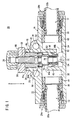
この流量制御弁10は、図1〜図5に示されるように、流体の供給・排出される第1及び第2ポート(ポート)12、14を有したボディ16と、前記ボディ16の中央部に設けられ、前記第1ポート12から第2ポート14へと流通する圧力流体(例えば、圧縮エア)の流通状態を制御する弁機構(弁部)18と、前記弁機構18による圧力流体の流量を手動で制御するためのハンドル20とを含む。
As shown in FIGS. 1 to 5, the
なお、図1は、弁機構18を構成するニードルバルブ(ロッド)54(後述する)によって第1ポート12と第2ポート14との連通が遮断された全閉状態を示している。
FIG. 1 shows a fully closed state in which communication between the
ボディ16は、一直線上に延在する第1円筒部22と、該第1円筒部22の軸線方向に沿った略中央部に接続される第2円筒部24とを有し、前記第2円筒部24が、第1円筒部22の軸線に対して直交するように接合され、上方へと所定高さで延在している。この第1円筒部22と第2円筒部24との接合部位近傍には、該第1円筒部22の軸線と略直交し、図示しないボルトの挿通される一対の取付孔26が形成される。そして、取付孔26に挿通された前記ボルトを介して流量制御弁10が図示しない他の装置に固定される。
The
第1円筒部22の一端部には、圧力流体の導入される第1ポート12が開口し、他端部には、前記圧力流体が排出される第2ポート14が開口している。そして、第1及び第2ポート12、14には、該第1及び第2ポート12、14の開口部に装着された接続ユニット28a、28bを介してチューブ30a、30bがそれぞれ接続される。
A
すなわち、例えば、図示しない圧力流体供給源からチューブ30aを通じて供給される圧力流体が第1ポート12に導入されると共に、前記ボディ16内を流通した圧力流体が、前記第2ポート14に接続されたチューブ30bを通じて他の流体圧機器(例えば、シリンダ)へと供給されることとなる。
That is, for example, a pressure fluid supplied through a
一方、第1円筒部22の内部には、第1及び第2ポート12、14から軸線方向に沿って延在する第1及び第2通路(流路)32、34がそれぞれ形成されると共に、前記第1通路32と第2通路34との間に連通室36が形成される。
On the other hand, first and second passages (flow paths) 32 and 34 extending along the axial direction from the first and
この第1及び第2通路32、34には、接続ユニット28a、28bに近接してリング状のパッキン38がそれぞれ装着されると共に、該パッキン38に隣接した位置にはリング状のスペーサ40がそれぞれ装着されている。なお、スペーサ40は、第1及び第2通路32、34に形成された段部に係合され、第1円筒部22の中央側への移動が規制されて位置決めされると共に、該スペーサ40に隣接したパッキン38の移動も前記スペーサ40によって規制されて位置決めされる。
In the first and
そして、第1及び第2ポート12、14から挿入されたチューブ30a、30bは、その外周面にパッキン38が当接し、該チューブ30a、30bの外周側を通じた圧力流体の外部への漏出が防止される。
The
また、第1通路32の端部には、該第1通路32の延在方向に対して直交し、連通室36に臨む第1壁部42が設けられ、前記第1壁部42と第1通路32の内壁面との間に開口した連通路44aを介して連通室36と連通している。
In addition, a
同様に、第2通路34の端部には、該第2通路34の延在方向に対して直交し、連通室36に臨む第2壁部46が設けられ、前記第2壁部46と第2通路34の内壁面との間に開口した連通路44bを介して連通室36と連通している。
Similarly, a
なお、第1壁部42は、第1通路32の内部において下方から上方に向かって延在し、該第1通路32において連通路44aが上方に形成されると共に、第2壁部46は、第2通路34の内部において上方から下方に向かって延在し、該第2通路34において連通路44bが下方に形成される。
The
すなわち、第1通路32における連通路44aと第2通路34における連通路44bとが、第1円筒部22の軸線と直交する方向に沿って互い違いとなるように形成されている。
That is, the
連通室36は、第2円筒部24と同軸上に形成され、その内部には、弁機構18の一部が挿入される。
The
第2円筒部24は、上方に向かって開口し、その内部には、弁機構18の装着される装着孔48が鉛直方向に延在するように形成され、前記装着孔48が第1円筒部22の連通室36と連通している。すなわち、装着孔48は、第1円筒部22の連通室36と同軸上となるように形成される。
The second
弁機構18は、第2円筒部24の装着孔48に対して圧入されたバルブホルダ(サブボディ)50と、前記バルブホルダ50の下部に装着される筒状のシートリング(シート部材)52と、前記バルブホルダ50及びシートリング52の内部に挿通され軸線方向(矢印A、B方向)に変位するニードルバルブ54とを含む。
The
バルブホルダ50は、円筒状に形成され、外周面に一組の凸部56a、56bが互いに所定間隔離間して形成される。そして、一方の凸部56aは、例えば、ローレットからなり、装着孔48の溝部に係合されることによって第2円筒部24に対する回り止めがなされ、且つ、他方の凸部56bが、別の溝部に係合されることにより、前記装着孔48とバルブホルダ50との間を通じた圧力流体の漏出が阻止される。この際、バルブホルダ50の上端部が、第2円筒部24の上端部に対して若干だけ突出するように装着される。
The
バルブホルダ50の下端部には、半径内方向に若干だけ縮径した保持部58が形成されると共に、前記保持部58の上端部には、半径内方向に窪んだ環状溝60が形成される。そして、保持部58には、該保持部58の外周面を覆うようにシートリング52が装着され、前記シートリング52の上端部に形成されたフック(折曲部)66(後述する)が前記環状溝60に挿入されて係合される。これにより、バルブホルダ50の下端部にシートリング52が一体的に接続される。
At the lower end of the
また、保持部58の下端面58aは、バルブホルダ50の軸線に対して直交した平面状に形成される。
Further, the
一方、バルブホルダ50の内部には、軸線方向(矢印A、B方向)に沿ってニードルバルブ54の挿通されるバルブ孔62が一定径で形成され、該バルブ孔62の上端部には、雌ねじの刻設された第1ねじ部64が設けられる。なお、第1ねじ部64は、バルブ孔62の内周径に対して若干だけ半径内方向に縮径して形成される。
On the other hand, a
シートリング52は、例えば、金属製の薄板材からプレス成形によって形成され、連通室36の内部に設けられる。このシートリング52は、上端部に形成されてバルブホルダ50に接続される大径部68と、下端部に形成されてニードルバルブ54の着座する小径部70と、前記大径部68と小径部70との間に形成される中間部72とから構成される。この大径部68が、シートリング52において最も大きな直径で形成され、前記中間部72が前記大径部68に対して縮径した小さな直径で形成されると共に、前記小径部70が前記中間部72に対してさらに縮径した直径で形成される。なお、このシートリング52は、金属製材料からプレス成形によって形成される場合に限定されるものではなく、例えば、樹脂製材料から成形することによって形成するようにしてもよい。
The
すなわち、シートリング52は、上端部から下端部に向かって段階的に縮径するように形成される。なお、上述した大径部68、中間部72及び小径部70は、同軸上となるように形成される。
That is, the
大径部68の上端部には、半径内方向に向かって所定角度で折曲したフック66が形成され、前記大径部68がバルブホルダ50の保持部58を覆うように圧入された際、フック66が環状溝60に係合されると共に、該保持部58の下端部が、前記大径部68と中間部72との境界部位に設けられた段付部(当接部)74に当接する。段付部74は、大径部68の下端部に対して半径内方向に直角に折曲され、中間部72の上端部に接合される。
A
これにより、シートリング52をバルブホルダ50の保持部58に装着する際、段付部74が該保持部58の端部に当接することによって係止され、前記バルブホルダ50に対する軸線方向(矢印A、B方向)に沿った位置決めがなされる。すなわち、上述した保持部58の下端面58aと段付部74は、バルブホルダ50とシートリング52とが組み付けられた際、互いに同軸状となるように位置決め可能な位置決め機構として機能する。
Thus, when the
また、この際、段付部74に対して保持部58の下端面(面)58aが当接することによって、バルブホルダ50とシートリング52との同軸度が確保され、同軸上に配置される。すなわち、バルブホルダ50とシートリング52とが、段付部74と保持部58との当接作用下に同軸上で位置決めされる。
At this time, the lower end surface (surface) 58a of the holding
中間部72には、シートリング52の軸線と直交するように複数(例えば、4個)の連通ポート76が周面に沿って形成され、該中間部72の外部と内部とを連通している。この連通ポート76は、中間部72の周方向に沿って等間隔離間して形成される。この連通ポート76は、シートリング52がプレス成形によって形成される際に同時に形成される。換言すれば、連通ポート76を形成するために別の加工工程を設ける必要がない。
A plurality of (for example, four)
小径部70には、中間部72との接合部位近傍が半径内方向に突出し、ニードルバルブ54が着座する着座部78が形成されると共に、その下端部には、半径外方向に拡径したフランジ80が形成される。
The small-
そして、小径部70の外周側には、ゴム等の弾性材料からなる筒状のシール部材82が装着される。このシール部材82の外周面には、上方且つ半径外方向に向かって所定角度傾斜したリブ84が形成され、該リブ84が、連通室36内において第1壁部42と第2壁部46にそれぞれ当接する。
A
これにより、連通室36内において、シートリング52の外周側と第1及び第2壁部42、46との間を通じた圧力流体の流通がシール部材82によって遮断される。また、シール部材82は、中間部72と小径部70との境界部位となる段差部とフランジ80との間に保持されているため、軸線方向(矢印A、B方向)に変位してしまうことがなく位置決めされる。
Thereby, in the
ニードルバルブ54は、軸線方向(矢印A、B方向)に沿って所定長さを有する軸体からなり、その上端部が、バルブホルダ50及び第2円筒部24の上端部に対して上方に突出してハンドル20が連結される。また、ニードルバルブ54の外周面には、上端部近傍にねじの刻設された第2ねじ部86が形成され、バルブホルダ50の第1ねじ部64に噛合される。すなわち、ハンドル20を介してニードルバルブ54を回転させることにより、該ニードルバルブ54がバルブホルダ50との螺合作用下に軸線方向(矢印A、B方向)に沿って進退動作する。
The
一方、ニードルバルブ54の下端部には、先端に向かって徐々に縮径し、シートリング52の小径部70に挿通自在な制御部88が形成される。この制御部88は、最も先端に設けられる第1制御面90と、該第1制御面90の上方に形成される第2制御面92とを有する。第1制御面90は、第2制御面92と比較し、ニードルバルブ54の軸線に対する傾斜角度が大きく設定されている。すなわち、第1制御面90は、第2制御面92に対してより先細状となるように形成されている。
On the other hand, at the lower end portion of the
そして、ニードルバルブ54が、図1に示される状態から上方へ変位し、シートリング52の着座部78から第2制御面92が離間することにより、前記着座部78と第2制御面92との間を通じて圧力流体がシートリング52における中間部72から小径部70側へと流通する。
Then, the
また、制御部88の上部には、該制御部88に対して拡径したストッパ部94が形成され、前記ストッパ部94の外周面に装着されたOリング96が常にバルブホルダ50におけるバルブ孔62の内周面に摺接している。これにより、シートリング52の内部に導入された圧力流体がOリング96によってバルブ孔62を通じて外部へと漏出することが阻止される。
Further, a
そして、ニードルバルブ54が軸線方向に沿って変位した際、ストッパ部94の上端がバルブホルダ50のバルブ孔62に沿って変位し、半径内方向に突出した第1ねじ部64の下端部に当接することによって上方(矢印B方向)への変位が規制される。一方、ストッパ部94の下端部が、シートリング52における小径部70と中間部72との境界部に当接することによって下方(矢印A方向)への変位が規制される。すなわち、ストッパ部94は、ニードルバルブ54の軸線方向(矢印A、B方向)に沿った変位量を規制するために設けられている。
When the
また、ボディ16を構成する第2円筒部24の上方には、該第2円筒部24と同軸上にロックナット98が設けられ、前記ロックナット98の中央にはニードルバルブ54の第2ねじ部86が螺合される。ロックナット98を螺回させることにより、該ロックナット98をニードルバルブ54に対して軸線方向(矢印A、B方向)に相対変位させることができる。そして、ハンドル20を介してニードルバルブ54を回転させ、ボディ16の内部を流通する圧力流体が所望流量となる位置に変位させた後、ロックナット98を螺回させてバルブホルダ50の上端部に当接する位置まで変位させることにより、前記ニードルバルブ54の回転変位が規制されるため、該ニードルバルブ54による流量制御された状態で維持される。
A
本発明の実施の形態に係る流量制御弁10は、基本的には以上のように構成されるものであり、次に、前記流量制御弁10を構成する弁機構18の組み付け方法について説明する。
The
先ず、外周面にOリング96の装着されたニードルバルブ54を、バルブホルダ50のバルブ孔62に対して下方から挿入し、その第2ねじ部86を前記バルブ孔62に設けられた第1ねじ部64に螺合させながら上方(矢印B方向)へと挿入していく。この際、Oリング96は、バルブホルダ50のバルブ孔62に摺接している。
First, the
次に、バルブホルダ50の保持部58に対して下方からシートリング52の大径部68を圧入し、前記保持部58の下端面58aを前記シートリング52の段付部74に当接させる。そして、シートリング52のフック66を図示しない加締用治具で半径内方向へと押圧し、該フック66を折曲させて前記保持部58に形成された環状溝60へと係合させる。これにより、バルブホルダ50に対してシートリング52を圧入し、且つ、該バルブホルダ50の保持部58と前記シートリング52の段付部74とを当接させることによって互いに同軸上に配置した状態で一体的に連結される。
Next, the large-
この際、バルブホルダ50とシートリング52との同軸度が確保されることにより、該バルブホルダ50に螺合されたニードルバルブ54と前記シートリング52とも同軸上に配置されることとなる。
At this time, since the coaxiality between the
そして、シートリング52の小径部70にシール部材82を装着した後、バルブホルダ50より上方に突出したニードルバルブ54の第2ねじ部86にロックナット98を螺合させ回転させることにより下方(矢印A方向)に向かって移動させる。
After the
最後に、ニードルバルブ54の上端部にハンドル20を圧入した後、ニードルバルブ54を含むバルブホルダ50と前記シートリング52の組付体を、ボディ16の第2円筒部24から装着孔48へと圧入し、該バルブホルダ50の外周面に設けられた凸部56aを前記装着孔48の溝部に係合させることによって該バルブホルダ50が回り止めされた状態で固定される。
Finally, after the
このように、弁機構18を構成するバルブホルダ50及びシートリング52において、該バルブホルダ50の軸線と直交するように保持部58の下端面58aと形成すると共に、大径部68と中間部72との間にシートリング52の軸線と直交するように段付部74を形成している。そのため、バルブホルダ50とシートリング52を組み付ける際、その保持部58の下端面58aと段付部74とを当接させ、且つ、前記シートリング52の大径部68を前記保持部58の外周面に対して圧入することにより、前記バルブホルダ50及びシートリング52の軸線に対する下端面58a及び段付部74の直角度が確保される。そのため、バルブホルダ50とシートリング52とを同軸上に配置することができる。
Thus, in the
すなわち、バルブホルダ50の下端部にシートリング52を組み付けるという簡便な作業で、前記バルブホルダ50とシートリング52とを確実且つ容易に同軸上となるように配置して連結することができる。
That is, the
その結果、バルブホルダ50に螺合されたニードルバルブ54とシートリング52とを同軸上とすることができ、バルブホルダ50に沿ってニードルバルブ54を変位させた際、該ニードルバルブ54の制御部88と着座部78との離間距離を半径方向に均一とすることができ、その間隙を通じて流通する圧力流体の流量を高精度に制御することが可能となる。
As a result, the
次に、上述したように組み付けられた流量制御弁の動作並びに作用効果について簡単に説明する。なお、ここでは、図1に示されるように、弁機構18を構成するニードルバルブ54が、ハンドル20の回転作用下に下降し、前記ニードルバルブ54によって第1ポート12と第2ポート14との連通が遮断された全閉状態を初期状態として説明する。
Next, operations and effects of the flow control valve assembled as described above will be briefly described. Here, as shown in FIG. 1, the
この初期状態において、チューブ30aを通じて第1ポート12に圧力流体が供給され、連通路44aを通じて連通室36内へと供給されている。なお、連通室36内に導入された圧力流体は、シートリング52の外周側に設けられたシール部材82によって該シートリング52の外周側を通じて下流となる第2ポート14側に流通することが阻止される。そして、図示しない作業者がロックナット98を螺回させて上方へと移動させ、ニードルバルブ54の回転変位が規制された状態を解除した後、ハンドル20を把持して回転させることにより、ニードルバルブ54がバルブホルダ50との螺合作用下に回転しながら上方(矢印B方向)へと変位する。
In this initial state, the pressure fluid is supplied to the
これにより、ニードルバルブ54は、制御部88の第2制御面92が着座部78に当接した状態から該着座部78に対して徐々に離間し、第2制御面92と前記着座部78との間の間隙が徐々に拡大する。そして、連通室36内に導入された圧力流体が、シートリング52の連通ポート76から該シートリング52の内部に流通し、ニードルバルブ54の制御部88と着座部78との間を通じて小径部70側(矢印A方向)へと流通する。この際、圧力流体は、ニードルバルブ54の制御部88と着座部78との間の間隙の大きさに比例した流量に制御される。この圧力流体は、連通室36内から連通路44bを通じて第2通路34へと流通した後、第2ポート14に接続されたチューブ30bを通じて他の流体圧機器へと所望の流量で流通する。
As a result, the
すなわち、ニードルバルブ54の軸線方向(矢印A、B方向)に沿った変位量と、連通室36を通じて第2ポート14側へと流通する圧力流体の流量とが比例する。換言すれば、ニードルバルブ54の変位量を制御することによって圧力流体の流量が制御されることとなる。
That is, the displacement amount of the
また、ハンドル20をさらに回転させ、ニードルバルブ54の第1制御面90が着座部78に臨む位置まで移動させることにより、第2制御面92に対して傾斜角度の大きく設定された第1制御面90と前記着座部78との間を通じて流通する圧力流体の流量をより一層増大させることができる。
Further, the
一方、圧力流体の流量を減少させる場合には、前述とは反対方向にハンドル20を回転させ、ニードルバルブ54をバルブホルダ50に沿って下方(矢印A方向)へと移動させる。これにより、制御部88が着座部78へと接近し、該制御部88と着座部78との間の間隙が徐々に小さくなるため、該間隙を通じて下流側へと流通する圧力流体の流量が減少することとなる。そして、ハンドル20をさらに回転させ、ニードルバルブ54におけるストッパ部94の下端部が着座部78に当接することにより、該ニードルバルブ54の下方への移動が規制され、制御部88の第2制御面92が前記着座部78に当接した全閉状態となる。
On the other hand, when the flow rate of the pressure fluid is decreased, the
このように、流量制御弁10において所望流量に制御された流体が、第2ポート14からチューブ30bを介して他の流体圧機器へと供給され、その動作が制御される。
In this way, the fluid controlled to the desired flow rate in the flow
以上のように、本実施の形態では、流量制御弁10を構成するバルブホルダ50とシートリング52とを組み付ける際、該バルブホルダ50における保持部58にシートリング52を圧入し、且つ、該保持部58の下端面58aに前記シートリング52の段付部74を当接させることにより、前記バルブホルダ50及びシートリング52の軸線と直交した下端面58a及び段付部74を介して前記バルブホルダ50とシートリング52とを確実且つ容易に同軸上として組み付けることができる。
As described above, in this embodiment, when the
その結果、バルブホルダ50の軸線に沿って移動するニードルバルブ54を、シートリング52と同軸上に配置することができるため、前記ニードルバルブ54を着座部78に対して高精度に着座できると共に、前記ニードルバルブ54を軸線方向に沿って変位させた際、制御部88と前記着座部78との間に形成される間隙を半径方向に均一とし、該間隙を流通する圧力流体の流量を高精度に制御することができる。
As a result, the
また、シートリング52が、薄板材をプレス成形することによって簡便且つ低コストで生産することができるため、弁本体を切削加工によって製造している従来技術に係る流量制御弁と比較し、低コストで製造することが可能となる。同様に、シートリング52の連通ポート76もプレス成形時に容易に形成することができるため、前記連通ポート76を切削加工等によって別個に形成していた場合と比較し、その製造工程の短縮化を図ることができ、流量制御弁10の生産性を向上することができる。
Further, since the
なお、本発明に係る流量制御弁及びその組付方法は、上述の実施の形態に限らず、添付の請求項に記載された本発明の要旨を逸脱することなく、種々の構成を採り得ることはもちろんである。 The flow rate control valve and the assembly method thereof according to the present invention are not limited to the above-described embodiments, and can adopt various configurations without departing from the gist of the present invention described in the appended claims. Of course.
Claims (10)
前記ポート(12、14)と、該ポート(12、14)から供給された流体が流通する一組の流路(32、34)とを有するボディ(16)と、
前記ボディ(16)の内部に装着され、前記ロッド(54)が進退自在に螺合されるサブボディ(50)と、
前記サブボディ(50)の端部に連結され、前記弁部(18)の着座する着座部(78)と、前記一方の流路(32)と他方の流路(34)とを連通する孔部(76)とを有した筒状のシート部材(52)と、
を備え、
前記シート部材(52)は、プレス成形により形成され、前記サブボディ(50)の端部を覆うように装着され、半径内方向に折曲される折曲部(66)を有し、前記サブボディ(50)の端部には、半径内方向に窪んだ環状溝(60)が形成され、前記環状溝(60)に前記折曲部(66)が係合されることで、前記シート部材(52)が前記サブボディ(50)に係合されることを特徴とする流量制御弁。 In the flow control valve (10) capable of controlling the flow rate of the fluid flowing between the pair of ports (12, 14) by displacing the rod (54) having the valve portion (18) in the axial direction,
A body (16) having the ports (12, 14) and a pair of flow paths (32, 34) through which the fluid supplied from the ports (12, 14) flows;
A sub-body (50) mounted inside the body (16), and wherein the rod (54) is screwed forward and backward;
A hole connected to the end of the sub-body (50) and communicating between the seat (78) on which the valve (18) is seated, the one channel (32) and the other channel (34). A cylindrical sheet member (52) having (76);
Equipped with a,
The sheet member (52) is formed by press molding, is mounted so as to cover an end of the sub body (50), and has a bent portion (66) bent inward in the radial direction. 50), an annular groove (60) recessed radially inward is formed, and the bent portion (66) is engaged with the annular groove (60), whereby the sheet member (52) is formed. ) flow control valve, wherein the Rukoto engaged with the sub-body (50).
前記サブボディ(50)及び前記シート部材(52)には、該サブボディ(50)と該シート部材(52)とを同軸上に配設可能な位置決め機構を備えることを特徴とする流量制御弁。 The flow control valve according to claim 1, wherein
The flow control valve according to claim 1, wherein the sub body (50) and the seat member (52) are provided with a positioning mechanism capable of coaxially arranging the sub body (50) and the seat member (52).
前記位置決め機構は、前記サブボディ(50)の端部に形成され、該サブボディ(50)の軸線に対して直交する面(58a)と、
前記シート部材(52)において、該シート部材(52)の軸線と直交し、前記面(58a)の当接する当接部(74)とからなることを特徴とする流量制御弁。 The flow control valve according to claim 2,
The positioning mechanism is formed at an end of the sub body (50), and a surface (58a) orthogonal to the axis of the sub body (50);
The flow rate control valve of the seat member (52), comprising a contact portion (74) perpendicular to the axis of the seat member (52) and contacting the surface (58a).
前記シート部材(52)の外周側には、前記ボディ(16)の内壁面に当接し、一方の流路(32)と他方の流路(34)との連通を遮断するシール部材(82)が装着され、前記シール部材(82)の外周面には、前記サブボディ(50)側且つ半径外方向に向かって傾斜したリブ(84)が形成され、該リブ(84)が、前記ボディ(16)の内壁面に当接することを特徴とする流量制御弁。 The flow control valve according to claim 1, wherein
A seal member (82) that contacts the inner wall surface of the body (16) and blocks communication between one flow path (32) and the other flow path (34) on the outer peripheral side of the seat member (52). And a rib (84) inclined toward the sub-body (50) side and radially outward is formed on the outer peripheral surface of the seal member (82). The rib (84) is formed on the body (16). contact to the flow control valve, wherein Rukoto the inner wall surface of).
前記シート部材(52)は、前記サブボディ(50)に対して圧入されることを特徴とする流量制御弁。 The flow control valve according to claim 1, wherein
The flow rate control valve, wherein the seat member (52) is press-fitted into the sub-body (50).
前記環状溝(60)は、前記サブボディ(50)の下端部に形成され、半径内方向に若干だけ縮径した保持部(58)に設けられることを特徴とする流量制御弁。 The flow control valve according to claim 1 , wherein
The flow rate control valve according to claim 1, wherein the annular groove (60) is formed at a lower end portion of the sub body (50) and is provided in a holding portion (58) slightly reduced in diameter in the radial direction.
前記シート部材(52)は、上端部に形成され前記サブボディ(50)に接続される大径部(68)と、下端部に形成され前記ロッド(54)の着座する小径部(70)と、前記大径部(68)と前記小径部(70)との間に形成される中間部(72)とから構成されることを特徴とする流量制御弁。 The flow control valve according to claim 1, wherein
The seat member (52) includes a large-diameter portion (68) formed at an upper end portion and connected to the sub-body (50), a small-diameter portion (70) formed at the lower end portion and seated by the rod (54), A flow control valve comprising an intermediate portion (72) formed between the large diameter portion (68) and the small diameter portion (70).
前記中間部(72)には、前記シート部材(52)の軸線と直交するように前記孔部(76)が周面に沿って複数形成され、該孔部によって前記中間部(72)の外部と内部とが連通することを特徴とする流量制御弁。 The flow control valve according to claim 7 ,
A plurality of the hole portions (76) are formed in the intermediate portion (72) along the circumferential surface so as to be orthogonal to the axis of the sheet member (52), and the hole portions are provided outside the intermediate portion (72). A flow control valve characterized in that the inside communicates with the inside.
前記ロッド(54)の下端部には、先端に向かって徐々に縮径し、前記シート部材(52)に挿通自在な制御部(88)が形成され、前記制御部(88)は、最も先端に設けられる第1制御面(90)と、該第1制御面(90)の上方に形成される第2制御面(92)とからなり、前記第1制御面(90)が、前記第2制御面(92)と比較して前記ロッド(54)の軸線に対する傾斜角度が大きく設定されることを特徴とする流量制御弁。 The flow control valve according to claim 1, wherein
At the lower end of the rod (54), there is formed a control part (88) that gradually decreases in diameter toward the tip and can be inserted into the sheet member (52). And a second control surface (92) formed above the first control surface (90), wherein the first control surface (90) is the second control surface (90). The flow rate control valve characterized in that an inclination angle with respect to the axis of the rod (54) is set larger than that of the control surface (92).
前記ロッド(54)を進退自在に保持するサブボディ(50)の端部に、筒状のシート部材(52)を圧入する工程と、
前記サブボディ(50)の軸線と直交した該サブボディ(50)の端部を、前記シート部材(52)の軸線と直交した当接部(74)に当接させ、前記サブボディ(50)とシート部材(52)とを同軸上に配置する工程と、
前記シート部材(52)の折曲部(66)を半径内方向に折曲させ、前記サブボディ(50)の環状溝(60)に係合させて加締める工程と、
を有することを特徴とする流量制御弁の組付方法。 A method for assembling the flow control valve (10) capable of controlling the flow rate of the fluid flowing between the pair of ports (12, 14) by displacing the rod (54) having the valve portion (18) in the axial direction. In
A step of press-fitting a tubular sheet member (52) into the end of the sub-body (50) that holds the rod (54) so as to be able to advance and retreat;
An end portion of the sub body (50) perpendicular to the axis of the sub body (50) is brought into contact with a contact portion (74) perpendicular to the axis of the seat member (52), so that the sub body (50) and the seat member (52) and a step of arranging them coaxially;
Bending the bent portion (66) of the sheet member (52) radially inward, engaging the annular groove ( 60) of the subbody (50), and crimping;
A method for assembling the flow control valve, comprising:
Priority Applications (1)
| Application Number | Priority Date | Filing Date | Title |
|---|---|---|---|
| JP2011534847A JP5561496B2 (en) | 2009-03-26 | 2009-08-12 | Flow control valve and its assembly method |
Applications Claiming Priority (4)
| Application Number | Priority Date | Filing Date | Title |
|---|---|---|---|
| JP2009076999 | 2009-03-26 | ||
| JP2009076999 | 2009-03-26 | ||
| JP2011534847A JP5561496B2 (en) | 2009-03-26 | 2009-08-12 | Flow control valve and its assembly method |
| PCT/JP2009/064477 WO2010109690A1 (en) | 2009-03-26 | 2009-08-12 | Flow rate control valve and assembly method therefor |
Publications (3)
| Publication Number | Publication Date |
|---|---|
| JP2012521522A JP2012521522A (en) | 2012-09-13 |
| JP2012521522A5 JP2012521522A5 (en) | 2012-10-25 |
| JP5561496B2 true JP5561496B2 (en) | 2014-07-30 |
Family
ID=41259416
Family Applications (1)
| Application Number | Title | Priority Date | Filing Date |
|---|---|---|---|
| JP2011534847A Active JP5561496B2 (en) | 2009-03-26 | 2009-08-12 | Flow control valve and its assembly method |
Country Status (7)
| Country | Link |
|---|---|
| US (1) | US8882078B2 (en) |
| EP (1) | EP2411711B1 (en) |
| JP (1) | JP5561496B2 (en) |
| KR (1) | KR101351364B1 (en) |
| CN (1) | CN102365483B (en) |
| TW (1) | TWI377307B (en) |
| WO (1) | WO2010109690A1 (en) |
Families Citing this family (12)
| Publication number | Priority date | Publication date | Assignee | Title |
|---|---|---|---|---|
| JP5282196B2 (en) * | 2010-01-21 | 2013-09-04 | Smc株式会社 | Flow control device |
| JP5527551B2 (en) * | 2011-05-20 | 2014-06-18 | Smc株式会社 | Flow control device |
| JP5986450B2 (en) * | 2012-08-06 | 2016-09-06 | サーパス工業株式会社 | Pneumatically operated valve and its assembly method |
| DE102014220675A1 (en) * | 2014-10-13 | 2016-04-14 | Ksb Aktiengesellschaft | Fitting with change seat system |
| CN105156731A (en) * | 2015-08-12 | 2015-12-16 | 无锡乐华自动化科技有限公司 | Piston type flow speed control valve |
| CN105135043A (en) * | 2015-08-12 | 2015-12-09 | 无锡乐华自动化科技有限公司 | Speed regulating method for circular disc type flow speed control valve |
| JP6960585B2 (en) * | 2018-12-03 | 2021-11-05 | Smc株式会社 | Flow controller and drive unit equipped with it |
| KR102224605B1 (en) * | 2018-12-13 | 2021-03-08 | 주식회사 디아 | opening and shutting apparatus of water supply equipment |
| US10808550B2 (en) * | 2018-12-13 | 2020-10-20 | Raytheon Technologies Corporation | Fan blade with integral metering device for controlling gas pressure within the fan blade |
| KR102199188B1 (en) | 2019-07-05 | 2021-01-07 | 한국생산기술연구원 | Pressure reducing control valve and method |
| CN112145709A (en) * | 2020-10-28 | 2020-12-29 | 宁波市鄞州超杰汽车零部件有限公司 | Speed regulating valve |
| KR102509593B1 (en) * | 2020-12-11 | 2023-03-14 | 프리시스 주식회사 | Vacuum valve |
Family Cites Families (31)
| Publication number | Priority date | Publication date | Assignee | Title |
|---|---|---|---|---|
| US928751A (en) * | 1904-05-11 | 1909-07-20 | Charles G Harcourt | Valve. |
| GB288845A (en) | 1927-01-01 | 1928-04-02 | Joseph Herman Dine | Improvements in and relating to stop valves and cocks |
| US2629580A (en) | 1947-11-04 | 1953-02-24 | Charles F Schultis | Replacement stem for faucets and the like |
| US3035780A (en) * | 1960-05-20 | 1962-05-22 | Renault | Fuel injection nozzles for internal combustion engines |
| BE795109A (en) * | 1972-02-07 | 1973-05-29 | Whitey Research Tool Co | VALVE VALVE |
| US4337788A (en) * | 1981-02-02 | 1982-07-06 | Smith International Inc. | High pressure valve |
| US4431021A (en) | 1981-12-24 | 1984-02-14 | Scaramucci John P | Needle valve |
| US4811929A (en) * | 1984-10-26 | 1989-03-14 | Scaramucci John P | Needle valve seat |
| US4732364A (en) * | 1984-12-17 | 1988-03-22 | Ameron Iron Works USA, Inc. | Wear resistant diamond cladding |
| US4714237A (en) * | 1986-05-14 | 1987-12-22 | Whitey Co. | Soft seat for metering valve |
| US5050633A (en) * | 1989-06-19 | 1991-09-24 | Emhart Inc. | Fluid valve |
| JPH0522952U (en) * | 1991-09-02 | 1993-03-26 | リンナイ株式会社 | Valve device |
| US5211317A (en) | 1992-06-18 | 1993-05-18 | Diamond George Bernard | Low pressure non-barrier type, valved dispensing can |
| DE19503821A1 (en) * | 1995-02-06 | 1996-08-08 | Bosch Gmbh Robert | Electromagnetically actuated valve |
| JPH08303630A (en) * | 1995-05-10 | 1996-11-22 | Fujikin:Kk | Controller |
| JP3738069B2 (en) * | 1995-11-15 | 2006-01-25 | 株式会社熊谷鉄工所 | Gate valve and gate valve unit |
| NL1010562C2 (en) * | 1998-11-16 | 2000-05-17 | Stork Bp & L Bv | Fill valve. |
| EP1161635A4 (en) * | 1999-02-19 | 2004-09-08 | Automatic Switch Co | Extended range proportional valve |
| US6840274B1 (en) * | 1999-06-01 | 2005-01-11 | Stant Manufacturing Inc. | Weldable mount for fuel systems component |
| JP4342660B2 (en) * | 1999-11-10 | 2009-10-14 | シーケーディ株式会社 | In-line type control valve |
| JP3418757B2 (en) * | 2000-03-17 | 2003-06-23 | 株式会社カクダイ | Stop valve |
| JP3445569B2 (en) * | 2000-09-18 | 2003-09-08 | Smc株式会社 | Pilot operated 2-port vacuum valve |
| US6824079B2 (en) | 2003-01-24 | 2004-11-30 | S. C. Johnson & Son, Inc. | Aerosol dispenser assembly and method of reducing the particle size of a dispensed product |
| JP2005030586A (en) * | 2003-07-07 | 2005-02-03 | Lg Electron Inc | Electromagnetic fluid control valve |
| EP1782300A2 (en) * | 2004-07-23 | 2007-05-09 | S.C.Johnson & Son, Inc | Method for designing aerosol spray dispensers |
| JP4798987B2 (en) | 2004-11-25 | 2011-10-19 | サーパス工業株式会社 | Flow control valve |
| US20060255308A1 (en) * | 2005-05-11 | 2006-11-16 | Borgwarner Inc. | Adjustable valve poppet |
| JP4565450B2 (en) * | 2005-06-24 | 2010-10-20 | リンナイ株式会社 | solenoid valve |
| DE102005058526B4 (en) * | 2005-12-08 | 2019-06-19 | Robert Bosch Gmbh | Two-stage valve for controlling fluids |
| JP4881137B2 (en) | 2006-11-24 | 2012-02-22 | 株式会社不二工機 | Flow control valve and refrigeration cycle |
| CN101205975A (en) | 2006-12-21 | 2008-06-25 | 黄作兴 | Cage type single seat regulating valve |
-
2009
- 2009-08-11 TW TW098126886A patent/TWI377307B/en active
- 2009-08-12 CN CN200980158346.1A patent/CN102365483B/en active Active
- 2009-08-12 JP JP2011534847A patent/JP5561496B2/en active Active
- 2009-08-12 US US13/254,073 patent/US8882078B2/en active Active
- 2009-08-12 EP EP09788039.7A patent/EP2411711B1/en active Active
- 2009-08-12 KR KR1020117022691A patent/KR101351364B1/en active IP Right Grant
- 2009-08-12 WO PCT/JP2009/064477 patent/WO2010109690A1/en active Application Filing
Also Published As
| Publication number | Publication date |
|---|---|
| WO2010109690A1 (en) | 2010-09-30 |
| JP2012521522A (en) | 2012-09-13 |
| US20110309284A1 (en) | 2011-12-22 |
| KR20110133575A (en) | 2011-12-13 |
| CN102365483A (en) | 2012-02-29 |
| CN102365483B (en) | 2015-04-29 |
| TW201035466A (en) | 2010-10-01 |
| US8882078B2 (en) | 2014-11-11 |
| TWI377307B (en) | 2012-11-21 |
| EP2411711B1 (en) | 2015-02-18 |
| KR101351364B1 (en) | 2014-01-14 |
| EP2411711A1 (en) | 2012-02-01 |
Similar Documents
| Publication | Publication Date | Title |
|---|---|---|
| JP5561496B2 (en) | Flow control valve and its assembly method | |
| JP4261559B2 (en) | Air operated valve | |
| TWI412677B (en) | Piloted poppet valve | |
| JP5723786B2 (en) | Fluid control valve | |
| TWI839455B (en) | Proportional flow control valve poppet with flow control needle | |
| EP2060798B1 (en) | Sealing structure for fluid pressure device | |
| US10030786B2 (en) | Adjustable damping valve arrangement | |
| JP7145884B2 (en) | Compact gas cylinder valve with residual pressure function | |
| WO2015159444A1 (en) | Fluid pressure cylinder | |
| JP5914936B2 (en) | Fluid pressure cylinder | |
| JP3922265B2 (en) | Integral power steering system | |
| KR101516700B1 (en) | Flow rate control apparatus | |
| JP5467470B2 (en) | Flow control valve | |
| JP4437554B2 (en) | Air operated valve | |
| US10968926B2 (en) | Fluid pressure device and method for manufacturing same | |
| CN211838589U (en) | Fluid micro-spraying device and execution assembly thereof | |
| US9383030B2 (en) | Check valve | |
| KR20220146126A (en) | Plunger valve apparatus capable of precision fluid control | |
| CN109715947B (en) | Valve, in particular pump valve for delivering abrasive and/or heterogeneous mixtures | |
| JP5583623B2 (en) | Cushion mechanism of fluid pressure cylinder | |
| JP7012367B2 (en) | Switching valve | |
| JPS6252189B2 (en) | ||
| JP2012202445A (en) | Cushion mechanism of fluid pressure cylinder | |
| JP2012211646A (en) | Valve device and method for assembling the valve device | |
| JPH06346938A (en) | Hydraulic buffer |
Legal Events
| Date | Code | Title | Description |
|---|---|---|---|
| A521 | Request for written amendment filed |
Free format text: JAPANESE INTERMEDIATE CODE: A523 Effective date: 20120727 |
|
| A621 | Written request for application examination |
Free format text: JAPANESE INTERMEDIATE CODE: A621 Effective date: 20120727 |
|
| A131 | Notification of reasons for refusal |
Free format text: JAPANESE INTERMEDIATE CODE: A131 Effective date: 20130806 |
|
| A521 | Request for written amendment filed |
Free format text: JAPANESE INTERMEDIATE CODE: A523 Effective date: 20131007 |
|
| TRDD | Decision of grant or rejection written | ||
| A01 | Written decision to grant a patent or to grant a registration (utility model) |
Free format text: JAPANESE INTERMEDIATE CODE: A01 Effective date: 20140430 |
|
| A61 | First payment of annual fees (during grant procedure) |
Free format text: JAPANESE INTERMEDIATE CODE: A61 Effective date: 20140527 |
|
| R150 | Certificate of patent or registration of utility model |
Ref document number: 5561496 Country of ref document: JP Free format text: JAPANESE INTERMEDIATE CODE: R150 |
|
| R250 | Receipt of annual fees |
Free format text: JAPANESE INTERMEDIATE CODE: R250 |
|
| R250 | Receipt of annual fees |
Free format text: JAPANESE INTERMEDIATE CODE: R250 |
|
| R250 | Receipt of annual fees |
Free format text: JAPANESE INTERMEDIATE CODE: R250 |
|
| R250 | Receipt of annual fees |
Free format text: JAPANESE INTERMEDIATE CODE: R250 |
|
| R250 | Receipt of annual fees |
Free format text: JAPANESE INTERMEDIATE CODE: R250 |
|
| R250 | Receipt of annual fees |
Free format text: JAPANESE INTERMEDIATE CODE: R250 |
|
| R255 | Notification that request for automated payment was rejected |
Free format text: JAPANESE INTERMEDIATE CODE: R2525 |
|
| R250 | Receipt of annual fees |
Free format text: JAPANESE INTERMEDIATE CODE: R250 |
|
| R250 | Receipt of annual fees |
Free format text: JAPANESE INTERMEDIATE CODE: R250 |