JP5558304B2 - Induction heating apparatus and heated object - Google Patents
Induction heating apparatus and heated object Download PDFInfo
- Publication number
- JP5558304B2 JP5558304B2 JP2010226389A JP2010226389A JP5558304B2 JP 5558304 B2 JP5558304 B2 JP 5558304B2 JP 2010226389 A JP2010226389 A JP 2010226389A JP 2010226389 A JP2010226389 A JP 2010226389A JP 5558304 B2 JP5558304 B2 JP 5558304B2
- Authority
- JP
- Japan
- Prior art keywords
- induction heating
- coil
- heating coil
- heated
- heating apparatus
- Prior art date
- Legal status (The legal status is an assumption and is not a legal conclusion. Google has not performed a legal analysis and makes no representation as to the accuracy of the status listed.)
- Expired - Fee Related
Links
Images


Landscapes
- General Induction Heating (AREA)
- Induction Heating Cooking Devices (AREA)
Description
この発明は、誘導加熱コイルを備えた誘導加熱装置および誘導加熱装置により加熱される被加熱体に関し、特に、誘導加熱コイルの温度上昇を抑制することができるものである。 The present invention relates to an induction heating device provided with an induction heating coil and a heated object heated by the induction heating device, and in particular, can suppress an increase in temperature of the induction heating coil.
従来の誘導加熱装置は、被加熱体に対して誘導加熱コイルが水平に配置されているものである(例えば、特許文献1参照)。 In a conventional induction heating apparatus, an induction heating coil is disposed horizontally with respect to a heated object (see, for example, Patent Document 1).
従来の誘導加熱装置は、誘導加熱コイルが水平に配置されているため、誘導加熱コイルの温度が上昇しやすく、誘導加熱コイルを構成するコイル導線の絶縁温度以上に誘導加熱コイル温度が上がらないようにするためにコストがかかるという問題があった。 In the conventional induction heating apparatus, since the induction heating coil is arranged horizontally, the temperature of the induction heating coil is likely to rise, so that the induction heating coil temperature does not rise above the insulation temperature of the coil wire constituting the induction heating coil. There was a problem that it was expensive to make.
この発明は上記のような課題を解決するためになされたものであり、誘導加熱コイルの温度上昇を抑制することができる誘導加熱装置および被加熱体を提供することを目的とする。 The present invention has been made to solve the above-described problems, and an object of the present invention is to provide an induction heating apparatus and an object to be heated that can suppress the temperature rise of the induction heating coil.
この発明は、被加熱体を加熱する誘導加熱コイルを備えた誘導加熱装置であって、
上記誘導加熱コイルは、コイル導線が径方向に複数回巻回され、上記径方向において上記コイル導線間は間隔を有し、
上記誘導加熱コイルは、上記コイル導線の巻回しを複数層形成し、当該各層において巻回方向を異なる方向として、当該各層を直列に接続して形成され、
当該各層の間隔を保持するとともに上記コイル導線間の間隔を上記誘導加熱コイルの積層方向に対して空間を空け保持するスペーサを備え、上記コイル導線間の径方向に開口を有するものである。
This invention is an induction heating apparatus provided with an induction heating coil for heating an object to be heated,
In the induction heating coil, a coil conductor is wound a plurality of times in the radial direction, and the coil conductor has a gap in the radial direction.
The induction heating coil is formed by forming a plurality of windings of the coil lead wire, connecting the layers in series, with the winding direction being different in each layer,
The spacing between the coil conductor keeps a distance of the respective layers comprise a spacer for retaining a space to the stacking direction of the induction heating coil is to also have an opening in the radial direction between the coil wires.
この発明の誘導加熱装置は、上記のように構成されているため、
誘導加熱コイルの温度上昇を抑制することができる。
Since the induction heating device of the present invention is configured as described above,
An increase in temperature of the induction heating coil can be suppressed.
実施の形態1.
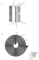
以下、本願発明の実施の形態について説明する。図1はこの発明の実施の形態1における誘導加熱装置の誘導加熱コイルの構成を示した断面図および正面図である。ここでは、誘導加熱装置として、誘導加熱を用いてインバータに回生された電力を消費する電子抵抗器を例に説明する。図1において、電気的エネルギー(電力)を誘導加熱の現象にて被加熱体2を加熱する誘導加熱コイル1は、被加熱体2に対して垂直となるように配設されている。また、誘導加熱コイル1の平面部は、被加熱体2の平面部と対向するように配設されている。そして、誘導加熱コイル1が生成した磁束を受け誘導加熱により加熱される被加熱体2と、被加熱体2の誘導加熱コイル1と相反する側に接続され被加熱体2を冷却する放熱器3と、被加熱体2の熱を断熱する断熱材4とを備える。尚、被加熱体2と放熱体3との間には熱伝導性グリースなどが介在されている。
Embodiments of the present invention will be described below. FIG. 1 is a cross-sectional view and a front view showing the configuration of the induction heating coil of the induction heating apparatus according to
そして、誘導加熱コイル1は、コイル導線5としての細い線がらせん状に巻回されている。このコイル導線5の間の間隔を形成、維持するために絶縁体で形成されている櫛状もしくはビーズ形状のスペーサ6を挟持して形成している。もしくは、線材として銅板を上記形状に加工して利用してもかまわない。また、コイル導線5の断面形状は、円形のほか多角形、複数の線材がより合わさった形状で形成されていてもよい。さらに、誘導加熱コイル1は熱エネルギーを反射する色に塗装することも考えられる。具体的には、誘導加熱コイル表面を塗装する色としては、例えば金色や銀色などの光沢があるものであればよい。尚、これらの内容は、以下の実施の形態においても同様であるため適宜説明を省略する。
And the
上記のように構成された実施の形態1の誘導加熱装置によれば、誘導加熱コイルが被加熱体に対して垂直となるように配置されているため、誘導加熱コイルもしくは被加熱体により加熱された空気が矢印Aのように上昇気流となり上部へ逃げ排熱される。また、コイル導線間が間隔を有しているため空気に触れる表面積が広くなり、伝熱面積が増加され、誘導加熱コイルの熱抵抗が低減される。さらにコイル導線に細い巻き線を使用しているため、伝熱面積が増加するとともに、誘導加熱コイルの巻き線が微小直径円柱のため自然対流時および強制対流時において、熱伝達特性が向上する。そのため、銅損および被加熱体からのふく射による熱を効率よく放熱させることができる。また、被加熱体と誘導加熱コイルとの間に断熱材を設けることにより、被加熱体から誘導加熱コイルへのふく射による熱伝導も減少することができる。 According to the induction heating apparatus of the first embodiment configured as described above, since the induction heating coil is arranged so as to be perpendicular to the heated object, the induction heating coil or the heated object is heated. As shown by the arrow A, the air becomes a rising air current and escapes to the upper part and is exhausted. Moreover, since there is a space between the coil conductors, the surface area in contact with air is increased, the heat transfer area is increased, and the thermal resistance of the induction heating coil is reduced. Further, since a thin winding is used for the coil conductor, the heat transfer area is increased, and the winding of the induction heating coil is a small diameter cylinder, so that heat transfer characteristics are improved during natural convection and forced convection. Therefore, it is possible to efficiently dissipate heat due to copper loss and radiation from the object to be heated. Further, by providing a heat insulating material between the heated body and the induction heating coil, heat conduction due to radiation from the heated body to the induction heating coil can also be reduced.
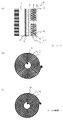
実施の形態2.
図2はこの発明の実施の形態2の誘導加熱装置の誘導加熱コイルの構成を示す断面図および正面図である。図において、上記実施の形態1と同様の部分は同一符号を付して説明を省略する。誘導加熱コイル1は、コイル導線5、15の巻回しを複数層形成し、各層のコイル導線5、15において巻回方向を異なる方向として、各層のコイル導線5、15を直列に接続して形成されている。具体的には、コイル導線5は反時計回りに巻回され、コイル導線15は時計回りに巻回され、コイル導線5とコイル導線15とは中心部分で接続され、2つは直列に接続され、ひとつの誘導加熱コイル1にて構成されているものである。そして、2つのコイル導線5とコイル導線15との間に空間をおき互いが接触しないようにスペーサ16により間隔が保たれている。
2 is a cross-sectional view and a front view showing the configuration of the induction heating coil of the induction heating apparatus according to
上記のように構成された実施の形態2の誘導加熱装置によれば、上記実施の形態1と同様の効果を奏するのはもちろんのこと、誘導加熱コイルの形状により巻き数が多くなり、大きなインダクタンスを得ることができる。また、外部回路との接続端子や、複数のコイルを並列接続するための端子を外側に設けることが容易となる。また、2層を直列に接続することにより誘導加熱コイルのインダクタンス値を大きくすることができる。 According to the induction heating device of the second embodiment configured as described above, the number of turns increases due to the shape of the induction heating coil as well as the same effect as that of the first embodiment. Can be obtained. Moreover, it becomes easy to provide a connection terminal with an external circuit and a terminal for connecting a plurality of coils in parallel. Further, the inductance value of the induction heating coil can be increased by connecting the two layers in series.
実施の形態3.
図3はこの発明の実施の形態3の誘導加熱装置の誘導加熱コイルの構成を示す断面図である。この実施の形態3では、端子を外側にする界磁方向を一致させる電子抵抗器の構成の例を示したものである。図において、上記各実施の形態と同様の部分は同一符号を付して説明を省略する。上記実施の形態2と同様に巻回方向の異なる2層のコイル導線5、15の中心部分で接続して直列に接続し、ひとつの誘導加熱コイル1を構成している。さらに、複数の被加熱体2を挟持するように複数の誘導加熱コイル1を配設することにより構成されている。
FIG. 3 is a cross-sectional view showing the configuration of the induction heating coil of the induction heating apparatus according to
上記のように構成された実施の形態3の誘導加熱装置によれば、上記各実施の形態と同様の効果を奏するのはもちろんのこと、被加熱体と誘導加熱コイルとを同時に冷やすことができ、かつ誘導加熱コイルの温度が上昇しても誘導加熱コイルの絶縁が破壊されないため、高温動作が可能になる。また巻回方向の違う2層をひとつの誘導加熱コイルとして構成することにより駆動回路や他の誘導加熱コイルと接続する場合の引き出し線を設ける必要がなく、誘導加熱コイルの外周で接続することができる。 According to the induction heating apparatus of the third embodiment configured as described above, the object to be heated and the induction heating coil can be cooled at the same time, as well as the same effects as those of the above embodiments. In addition, since the insulation of the induction heating coil is not broken even if the temperature of the induction heating coil rises, high temperature operation is possible. In addition, by configuring two layers with different winding directions as one induction heating coil, there is no need to provide a lead wire when connecting to a drive circuit or another induction heating coil, and it is possible to connect at the outer periphery of the induction heating coil. it can.
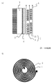
実施の形態4.
図4はこの発明の実施の形態4の誘導加熱装置の誘導加熱コイルの構成を示す断面図および正面図である。図において、上記各実施の形態と同様の部分は同一符号を付して説明を省略する。図において、誘導加熱コイル1は、コイル導線5、25の巻回しを複数層形成し、各層のコイル導線5、25は巻回方向を同一方向として、各層のコイル導線5、25を並列に接続して形成されている。そして、誘導加熱コイル1は、コイル導線5とコイル導線25との各層の各中心をずらして積層されている。
Embodiment 4 FIG.
FIG. 4 is a cross-sectional view and a front view showing the configuration of the induction heating coil of the induction heating apparatus according to Embodiment 4 of the present invention. In the figure, the same parts as those in the above embodiments are denoted by the same reference numerals, and description thereof is omitted. In the figure, the
上記のように構成された実施の形態4の誘導加熱装置によれば、上記各実施の形態と同様の効果を奏するのはもちろんのこと、各層のコイル導線が互い違いに配置されることにより、各層のコイル導線間の距離が広がるためコイル導線間の銅損によるコイル導線の被加熱体側の熱干渉を受けにくくすることができる。これにより、誘導加熱コイルが銅損および被加熱体からの輻射熱により加熱されることによる誘導加熱コイルの温度上昇が低減でき、誘導加熱コイルの温度上昇時のコイル導線間の絶縁を維持することができる。これにより高温で誘導加熱コイルを使用することができるため、この誘導加熱装置を用いた電子抵抗器の電力容量を大きくとることが可能である。 According to the induction heating apparatus of the fourth embodiment configured as described above, the effect similar to that of each of the above embodiments can be obtained, and the coil conductors of the respective layers are alternately arranged, so that each layer Since the distance between the coil conductors is increased, it is possible to make the coil conductor less susceptible to thermal interference on the heated body side of the coil conductor due to copper loss between the coil conductors. As a result, the induction heating coil is heated by the copper loss and the radiant heat from the object to be heated, so that the temperature rise of the induction heating coil can be reduced, and the insulation between the coil conductors can be maintained when the temperature of the induction heating coil rises. it can. Thereby, since the induction heating coil can be used at a high temperature, it is possible to increase the power capacity of the electronic resistor using this induction heating device.
実施の形態5.
図5はこの発明の実施の形態5の誘導加熱装置の誘導加熱コイルの構成を示す断面図および正面図である。図において、上記各実施の形態と同様の部分は同一符号を付して説明を省略する。図において、誘導加熱コイル1の正面側の中心部から風Bを当てるファン7を備えたものである。
5 is a cross-sectional view and a front view showing a configuration of an induction heating coil of an induction heating apparatus according to
上記のように構成された実施の形態5の誘導加熱装置によれば、上記各実施の形態と同様の効果を奏するのはもちろんのこと、誘導加熱コイルがファンにより強制冷却されているため、誘導加熱コイルが銅損および被加熱体からの輻射熱により加熱されることによる、誘導加熱コイルの温度上昇の低減と誘導加熱コイルの温度上昇時のコイル導線間の絶縁を維持することができる。そして、この構成ではファンにより誘導加熱コイル中心に向けて風A’が流れ、被加熱体を放射状の空気流れによりコイルが冷却できる。尚、風A’は上昇気流の風Aを含むものである。この構造では誘導加熱コイルは微小円形円柱群と考えることができ、誘導加熱コイルの銅線の周りの温度境界層が薄いため熱伝達特性が優れている。これにより高温でコイルを使用することができるため、当該誘導加熱装置を用いた電子抵抗器の電力容量を大きくとることができる。さらに、誘導加熱コイル温度が大きく変わらないため、誘導加熱コイルでの銅損の増加を抑えることができる。 According to the induction heating device of the fifth embodiment configured as described above, the induction heating coil is forcibly cooled by the fan as well as the same effects as those of the above embodiments. The heating coil is heated by the copper loss and the radiant heat from the object to be heated, so that the temperature rise of the induction heating coil can be reduced and the insulation between the coil conductors can be maintained when the temperature of the induction heating coil rises. In this configuration, the wind A ′ flows toward the center of the induction heating coil by the fan, and the coil can be cooled by the radial air flow in the heated object. Note that the wind A ′ includes the updraft wind A. In this structure, the induction heating coil can be considered as a group of minute circular cylinders, and the heat transfer characteristic is excellent because the temperature boundary layer around the copper wire of the induction heating coil is thin. Thereby, since a coil can be used at high temperature, the power capacity of the electronic resistor using the said induction heating apparatus can be taken large. Furthermore, since the induction heating coil temperature does not change greatly, an increase in copper loss in the induction heating coil can be suppressed.
また、図6に示すように、被加熱体2に誘導加熱コイル1と反する面上に直接フィン8を設置し、水平方向に複数のフィン8を配設する。これにより、誘導加熱コイル1により誘導加熱を直接フィン8により放熱することができる。この場合、被加熱体と放熱体との間に熱伝導グリースなどが不要となり、被加熱体の熱抵抗を下げることができ、誘導加熱コイル1の温度上昇を抑制することができる。
Moreover, as shown in FIG. 6, the
1 誘導加熱コイル、2,20 被加熱体、5,15,25 コイル導線、
6,16 スペーサ、7 ファン、8 フィン、21 通風孔、
A,A’,A”,B 風。
1 induction heating coil, 2,20 object to be heated, 5, 15, 25 coil conductor,
6,16 Spacer, 7 Fan, 8 Fin, 21 Ventilation hole,
A, A ', A ", B wind.
Claims (8)
上記誘導加熱コイルは、コイル導線が径方向に複数回巻回され、上記径方向において上記コイル導線間は間隔を有し、
上記誘導加熱コイルは、上記コイル導線の巻回しを複数層形成し、当該各層において巻回方向を異なる方向として、当該各層を直列に接続して形成され、
当該各層の間隔を保持するとともに上記コイル導線間の間隔を上記誘導加熱コイルの積層方向に対して空間を空け保持するスペーサを備え、上記コイル導線間の径方向に開口を有する誘導加熱装置。 An induction heating apparatus provided with an induction heating coil for heating an object to be heated,
In the induction heating coil, a coil conductor is wound a plurality of times in the radial direction, and the coil conductor has a gap in the radial direction.
The induction heating coil is formed by forming a plurality of windings of the coil lead wire, connecting the layers in series, with the winding direction being different in each layer,
An induction heating apparatus that includes a spacer that holds a space between the coil conductors and maintains a space between the coil conductors with a space in a stacking direction of the induction heating coils, and has an opening in a radial direction between the coil conductors .
上記誘導加熱コイルは、コイル導線が径方向に複数回巻回され、上記径方向において上記コイル導線間は間隔を有し、In the induction heating coil, a coil conductor is wound a plurality of times in the radial direction, and the coil conductor has a gap in the radial direction.
上記誘導加熱コイルは、上記コイル導線の巻回しを複数層形成し、当該各層において巻回方向を同一方向として、当該各層を並列に接続して形成され、The induction heating coil is formed by forming a plurality of windings of the coil conducting wire, with the winding direction being the same direction in each layer, and connecting the layers in parallel.
当該各層の間隔を保持するとともに上記コイル導線間の間隔を上記誘導加熱コイルの積層方向に対して空間を空け保持するスペーサを備え、上記コイル導線間の径方向に開口を有する誘導加熱装置。An induction heating apparatus that includes a spacer that holds a space between the coil conductors and maintains a space between the coil conductors with a space in a stacking direction of the induction heating coils, and has an opening in a radial direction between the coil conductors.
上記誘導加熱コイルと反する面上に直接設置され、水平方向に複数配設されたフィンを備えたことを特徴とする被加熱体。 A said heated body to be heated by induction heating device as claimed in any one of claims 7,
An object to be heated, comprising a plurality of fins that are directly installed on a surface opposite to the induction heating coil and arranged in the horizontal direction.
Priority Applications (1)
| Application Number | Priority Date | Filing Date | Title |
|---|---|---|---|
| JP2010226389A JP5558304B2 (en) | 2010-10-06 | 2010-10-06 | Induction heating apparatus and heated object |
Applications Claiming Priority (1)
| Application Number | Priority Date | Filing Date | Title |
|---|---|---|---|
| JP2010226389A JP5558304B2 (en) | 2010-10-06 | 2010-10-06 | Induction heating apparatus and heated object |
Publications (3)
| Publication Number | Publication Date |
|---|---|
| JP2012079646A JP2012079646A (en) | 2012-04-19 |
| JP2012079646A5 JP2012079646A5 (en) | 2012-11-15 |
| JP5558304B2 true JP5558304B2 (en) | 2014-07-23 |
Family
ID=46239629
Family Applications (1)
| Application Number | Title | Priority Date | Filing Date |
|---|---|---|---|
| JP2010226389A Expired - Fee Related JP5558304B2 (en) | 2010-10-06 | 2010-10-06 | Induction heating apparatus and heated object |
Country Status (1)
| Country | Link |
|---|---|
| JP (1) | JP5558304B2 (en) |
Family Cites Families (11)
| Publication number | Priority date | Publication date | Assignee | Title |
|---|---|---|---|---|
| JPS591355Y2 (en) * | 1981-07-13 | 1984-01-14 | 三洋電機株式会社 | induction heating coil |
| JPS598296A (en) * | 1982-07-03 | 1984-01-17 | 住友電気工業株式会社 | Coil for electromagnetic cooking device |
| JPS60202680A (en) * | 1984-03-28 | 1985-10-14 | 高周波熱錬株式会社 | Method of cooling multilayer multiwinding coil and multilayer multiwinding coil unit |
| JPH0396014U (en) * | 1990-01-24 | 1991-10-01 | ||
| JPH0541274A (en) * | 1991-08-06 | 1993-02-19 | Sharp Corp | Electromagnetic induction heating cooker |
| JPH11314996A (en) * | 1998-05-08 | 1999-11-16 | Digital Wave:Kk | Crystal producing method and equipment therefor |
| JP4995898B2 (en) * | 2007-04-17 | 2012-08-08 | 三菱電機株式会社 | Hot air generator and hand dryer using the same |
| JP4870642B2 (en) * | 2007-10-12 | 2012-02-08 | 三菱電機株式会社 | Induction heating coil and induction heating cooker |
| CN101260116A (en) * | 2008-04-21 | 2008-09-10 | 湖南有色凯铂生物药业有限公司 | Method for synthesizing 7-phenylacetamide-3-chloromethyl-4-cephalosporanic acid p-methoxybenzyl ester |
| WO2009130761A1 (en) * | 2008-04-22 | 2009-10-29 | 三菱電機株式会社 | Induction heating apparatus, warm air generator, and hand drying apparatus |
| JP5253199B2 (en) * | 2009-01-22 | 2013-07-31 | 三菱電機株式会社 | Regenerative resistor |
-
2010
- 2010-10-06 JP JP2010226389A patent/JP5558304B2/en not_active Expired - Fee Related
Also Published As
| Publication number | Publication date |
|---|---|
| JP2012079646A (en) | 2012-04-19 |
Similar Documents
| Publication | Publication Date | Title |
|---|---|---|
| JP6008160B1 (en) | Noise filter | |
| JP5553040B2 (en) | Electronic components | |
| US10867741B2 (en) | Pseudo edge-wound winding using single pattern turn | |
| JP6307449B2 (en) | Trance | |
| JP5558304B2 (en) | Induction heating apparatus and heated object | |
| EP3522181B1 (en) | Magnetic component with heat dissipation structure | |
| JP5558305B2 (en) | Induction heating apparatus and heated object | |
| JP6064943B2 (en) | Electronics | |
| JPWO2017208333A1 (en) | Magnetic parts | |
| JP2009105078A (en) | Heating coil for induction heating device | |
| JP4794725B2 (en) | Heating coil for induction heating device | |
| JP2009164012A (en) | Induction heating coil | |
| JP4824508B2 (en) | Litz wire coil | |
| JP4559834B2 (en) | Manufacturing method of heat conductor | |
| US20130187738A1 (en) | Electrical apparatus having a thermally conductive bobbin | |
| JP2015053369A (en) | Coil component and power supply device using the same | |
| US20230412016A1 (en) | Displacement body for a rotor and correspondingly configured rotor | |
| CN109524219B (en) | Transformer and power module with same | |
| JP2016127071A (en) | Reactor heat dissipation structure | |
| JP2016146414A (en) | Transformer | |
| JP2011155117A (en) | Heat dissipation structure of coil | |
| JP4915444B2 (en) | Heating coil for induction heating device | |
| JPH0723939Y2 (en) | Coil with cooling passage | |
| JP2014216129A (en) | Induction heating device and induction heating apparatus using the same | |
| JP4924683B2 (en) | Heating coil for induction heating device |
Legal Events
| Date | Code | Title | Description |
|---|---|---|---|
| A521 | Written amendment |
Free format text: JAPANESE INTERMEDIATE CODE: A523 Effective date: 20121001 |
|
| A621 | Written request for application examination |
Free format text: JAPANESE INTERMEDIATE CODE: A621 Effective date: 20121001 |
|
| A977 | Report on retrieval |
Free format text: JAPANESE INTERMEDIATE CODE: A971007 Effective date: 20131018 |
|
| A131 | Notification of reasons for refusal |
Free format text: JAPANESE INTERMEDIATE CODE: A131 Effective date: 20131029 |
|
| A521 | Written amendment |
Free format text: JAPANESE INTERMEDIATE CODE: A523 Effective date: 20131225 |
|
| A131 | Notification of reasons for refusal |
Free format text: JAPANESE INTERMEDIATE CODE: A131 Effective date: 20140212 |
|
| A521 | Written amendment |
Free format text: JAPANESE INTERMEDIATE CODE: A523 Effective date: 20140408 |
|
| TRDD | Decision of grant or rejection written | ||
| A01 | Written decision to grant a patent or to grant a registration (utility model) |
Free format text: JAPANESE INTERMEDIATE CODE: A01 Effective date: 20140507 |
|
| A61 | First payment of annual fees (during grant procedure) |
Free format text: JAPANESE INTERMEDIATE CODE: A61 Effective date: 20140604 |
|
| R150 | Certificate of patent or registration of utility model |
Ref document number: 5558304 Country of ref document: JP Free format text: JAPANESE INTERMEDIATE CODE: R150 |
|
| R250 | Receipt of annual fees |
Free format text: JAPANESE INTERMEDIATE CODE: R250 |
|
| R250 | Receipt of annual fees |
Free format text: JAPANESE INTERMEDIATE CODE: R250 |
|
| R250 | Receipt of annual fees |
Free format text: JAPANESE INTERMEDIATE CODE: R250 |
|
| R250 | Receipt of annual fees |
Free format text: JAPANESE INTERMEDIATE CODE: R250 |
|
| LAPS | Cancellation because of no payment of annual fees |