WO2009130761A1 - Induction heating apparatus, warm air generator, and hand drying apparatus - Google Patents
Induction heating apparatus, warm air generator, and hand drying apparatus Download PDFInfo
- Publication number
- WO2009130761A1 WO2009130761A1 PCT/JP2008/057743 JP2008057743W WO2009130761A1 WO 2009130761 A1 WO2009130761 A1 WO 2009130761A1 JP 2008057743 W JP2008057743 W JP 2008057743W WO 2009130761 A1 WO2009130761 A1 WO 2009130761A1
- Authority
- WO
- WIPO (PCT)
- Prior art keywords
- coil
- heating plate
- induction heating
- heating
- plate
- Prior art date
Links
Images


Classifications
-
- F—MECHANICAL ENGINEERING; LIGHTING; HEATING; WEAPONS; BLASTING
- F24—HEATING; RANGES; VENTILATING
- F24H—FLUID HEATERS, e.g. WATER OR AIR HEATERS, HAVING HEAT-GENERATING MEANS, e.g. HEAT PUMPS, IN GENERAL
- F24H3/00—Air heaters
- F24H3/02—Air heaters with forced circulation
- F24H3/04—Air heaters with forced circulation the air being in direct contact with the heating medium, e.g. electric heating element
- F24H3/0405—Air heaters with forced circulation the air being in direct contact with the heating medium, e.g. electric heating element using electric energy supply, e.g. the heating medium being a resistive element; Heating by direct contact, i.e. with resistive elements, electrodes and fins being bonded together without additional element in-between
-
- H—ELECTRICITY
- H05—ELECTRIC TECHNIQUES NOT OTHERWISE PROVIDED FOR
- H05B—ELECTRIC HEATING; ELECTRIC LIGHT SOURCES NOT OTHERWISE PROVIDED FOR; CIRCUIT ARRANGEMENTS FOR ELECTRIC LIGHT SOURCES, IN GENERAL
- H05B6/00—Heating by electric, magnetic or electromagnetic fields
- H05B6/02—Induction heating
- H05B6/10—Induction heating apparatus, other than furnaces, for specific applications
- H05B6/105—Induction heating apparatus, other than furnaces, for specific applications using a susceptor
- H05B6/108—Induction heating apparatus, other than furnaces, for specific applications using a susceptor for heating a fluid
Definitions
- the present invention relates to an induction heating apparatus that heats a fluid such as a gas or a liquid using induction heating.
- a coil is formed by winding a lead wire such as a litz wire around the outer periphery of a cylindrical case made of a non-magnetic material such as ceramic, and a heating element is provided inside the cylindrical case.
- the heating element is inductively heated by flowing a high-frequency current through the coil, and the fluid is heated by passing the fluid through the inside of the case in which the heating element is stored (Patent Document 1, FIG. 1).
- the heating element is formed by alternately laminating a flat first sheet and a corrugated second sheet made of SUS447J1 defined in JIS (Japanese Industrial Standard) standard of ferritic stainless steel having magnetism.
- the induction heating apparatus configured as described above, when a high-frequency current is passed through the coil, the sheet material is laminated so as to have a space and can be electrically conducted, and the current crossing the peripheral portion from the current along the peripheral portion. Is formed in a shape that facilitates flow, so that a heat transfer area can be secured, and the heating element in the central part inside the case generates more heat than the peripheral part. Since the fluid passing through the case flows more easily in the central portion than in the peripheral portion, it is uniformly heated by the heating element that generates heat in the central portion.
- Patent Document 2 discloses an induction heating device that heats a metal pan by induction heating for the purpose of cooking.
- the buoyancy generated when a pan made of a material having a high electrical conductivity such as aluminum or copper is heated by induction heating in order to make the temperature at the bottom of the pan uniform or reduced.
- a conductive plate in which six slits are radially formed from the center hole to the peripheral part between a coil for induction heating and a SUS-based magnetic container that is an object to be heated. Is used.
- One of the slit portions is connected to the outer peripheral edge of the conductive plate. In such a configuration, when a high-frequency current is passed through the induction heating coil, the induction current flows in the direction around the conductive plate. However, the induction current is blocked by the slit connecting the outer peripheral edge and the center hole, and is used for induction heating.
- the direction is changed in the same direction as the high-frequency current flowing in the coil, and flows along a slit that is not connected to the center hole and the outer peripheral edge.
- the induction current near the center of the conductive plate flows in the same direction as the high-frequency current flowing through the induction heating coil, the magnetic field near the center of the conductive plate is strengthened, and the temperature difference in each part of the bottom surface of the heated object is reduced. .
- Patent Document 3 discloses an induction heating device that induction-heats an object to be heated made of aluminum, copper, or a low magnetic permeability material having an electric conductivity equal to or higher than that for cooking.
- an electric conductor such as aluminum is provided between a heating coil for induction heating and an object to be heated.
- an induction current is generated in both, and the magnetic field generated by the induction current induced in the electric conductor and the object to be heated are heated.
- An induced current flows through the electric conductor and the object to be heated so that a superimposed magnetic field of the magnetic field generated by the current induced in the object prevents a change in the magnetic field generated by the heating coil.
- the change in the current distribution increases the equivalent series resistance of the heating coil and obtains the same output.
- the current value flowing through the heating coil can be reduced, the buoyancy acting on the object to be heated is reduced, and the electric conductor acts on the object to be heated by sharing a part of the buoyancy acting on the object to be heated. The buoyancy is reduced.
- the induction heating device disclosed in Patent Document 2 or 3 is not designed to heat a fluid such as a gas or a liquid in the first place, and therefore cannot efficiently heat the fluid. Also, even if it is used for fluid heating, the amount of heat generated by the electrical conductor provided between the coil for induction heating and the object to be heated is suppressed as small as possible, and the temperature distribution of the object to be heated is made uniform or efficiently heated. In order to do this, the electrical conductor is provided with slits, so in terms of the heat transfer area for fluid heating, the main heat transfer surface is a heated object such as a pan bottom, and the electric conductor is almost the heat transfer surface. It does not contribute.
- the present invention has been made to solve the above-described problems, and an induction heating apparatus that can increase the heat transfer area with a simple structure and efficiently heat a fluid such as a gas or a liquid. It is intended to be realized.
- An induction heating apparatus includes a coil and a nonmagnetic conductor, and includes at least one first heating plate that forms a flow path between the coil and the conductor, A second heating plate that forms a flow path between the first heating plate and a high-frequency power source that supplies a high-frequency current to the coil, wherein the first heating plate has a direction of magnetic flux generated by the coil; It has a slit extending in substantially the same direction.
- the present invention since the magnetic flux that has passed through the slit of the first heating plate reaches the second heating plate arranged on the outer side, all the heating plates are induction-heated to increase the heat transfer area. Thus, the present invention has a remarkable effect that the fluid can be heated.
- FIG. 1 It is a perspective view of the induction heating apparatus of Embodiment 1 which concerns on this invention. It is a disassembled perspective view of the induction heating apparatus shown in FIG. (A) And (b) is the top view and sectional drawing of a coil shown in FIG. 1, Comprising: The direction of the magnetic flux produced from a coil is shown.
- (A) is a perspective view of the first heating plate shown in FIG. 1
- (b) to (c) are cross-sectional views of the induction heating device shown in FIG. 1, showing the state of magnetic flux. It is side surface sectional drawing of the warm air generator using the induction heating apparatus shown in FIG. It is a perspective view of the perforation heating plate used as a comparative example of the first heating plate.
- FIG. 6 is a perspective view of an induction heating device according to a modification of the second embodiment.
- FIG. FIG. 10 is a perspective view of an induction heating device according to another modification of the second embodiment. It is a perspective view of the induction heating apparatus by Embodiment 3 which concerns on this invention. It is a disassembled perspective view of the induction heating apparatus shown in FIG. It is a perspective view of the induction heating apparatus by Embodiment 4 which concerns on this invention. It is side surface sectional drawing of the hand-drying apparatus by Embodiment 5 which concerns on this invention. It is a block diagram which shows the circuit structure of the power supply device used for the hand dryer shown in FIG.
- FIG. 10 is a perspective view of an induction heating device according to a modification of the sixth embodiment. It is sectional drawing of the induction heating apparatus shown in FIG. It is a disassembled perspective view of the induction heating apparatus by Embodiment 7 which concerns on this invention.
- FIG. 10 is a cross-sectional view of an induction heating device according to a modification of the seventh embodiment. It is a disassembled perspective view of the coil by Embodiment 8 which concerns on this invention. It is sectional drawing of the coil shown in FIG.
- induction heating device 10: flat coil, 11: support plate, 12: insulating case, 14: coil case (metal case), 18: cylindrical coil, 20: first heating plate, 21: slit, 22 : Outer end (coil), 23: outer periphery (first heating plate), 26: partition plate, 30: second heating plate, 32: cylindrical case, 40: spacer, 50: power supply device, 100: warm Wind generator, 101: air inlet, 102: jet outlet, 103: duct, 104: blower, 200: hand dryer, 202: housing, 203: duct, 204: blower, 206: hand insertion section, 208: air inlet , Ejection port (ejection nozzle), 210: electrical wiring, 212: ejection port (ejection nozzle), 250: power supply device, 252: switching element, 254: half-bridge circuit, 256: DC power supply, 258: half-blur Jidoraiba, 260: control unit, 300: hand dryer, 303: Duct, P: passage
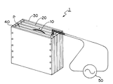
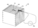
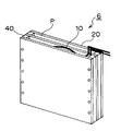
- FIG. 1 is a perspective view showing an induction heating device 1 according to Embodiment 1 of the present invention
- FIG. 2 is an exploded perspective view of the induction heating device 1 of FIG.
- the induction heating device 1 according to the first embodiment is roughly composed of a flat coil 10 formed in an arbitrary plane shape (circular shape in FIG. 2) by winding a conductive wire such as an enamel wire in a spiral shape, and on both sides thereof.
- a pair of first heating plates 20 disposed with a predetermined space separated by a spacer 40 and a pair of second heating plates 30 disposed with a predetermined space separated by a spacer 40 in a direction away from the coil 10.
- FIG. 1 is a perspective view showing an induction heating device 1 according to Embodiment 1 of the present invention
- FIG. 2 is an exploded perspective view of the induction heating device 1 of FIG.
- the induction heating device 1 according to the first embodiment is roughly composed of a flat coil 10 formed in an arbitrary plane shape (circular shape in FIG. 2) by wind
- the flat coil 10 is illustrated as being fixed to a plate-like support plate 11, but may be disposed inside an insulating case 12 made of an insulator such as resin or ceramics. However, it is also possible to construct the flat coil 10 that can stand on its own without using the support plate 11 by insulating and connecting the wound conductors (see FIG. 5).
- the pair of first heating plates 20 is made of nonmagnetic austenitic stainless steel
- the pair of second heating plates 30 is made of magnetic ferritic stainless steel.
- the constituent material of the first heating plate 20 may be a conductor material that is not a ferromagnetic material, and is preferably made of a material having a large volume resistivity, and more preferably Austenitic stainless steel SUS304 may be used as a mass-produced and inexpensive product.
- the constituent material of the second heating plate 30 may be the same as the constituent material of the first heating plate 20 or may be a nonmagnetic material (nonmagnetic austenitic stainless steel), but preferably Is a ferromagnetic metal such as ferritic stainless steel or marsanto stainless steel, and SUS430, a magnetic ferritic stainless steel, is most suitable from the viewpoint of low cost.
- the first heating plate 20 of the first embodiment has a plurality of slits 21 extending radially from the center.
- the slits 21 do not need to intersect at the center as shown in the figure, and may be independent from each other, but their inner ends are radially inward from the inner periphery of the coil 10 and their outer ends 22 are the first ones. It is configured not to reach the outer peripheral portion 23 of the heating plate 20. That is, the outer peripheral portion 23 of the first heating plate 20 is continuous in the circumferential direction without being divided by the slit 21, and the circumferential high-frequency current generated in the first heating plate 20 is caused by the slit 21 as described later.
- the first heating plate 20 can flow uniformly throughout the first heating plate 20 without being blocked, and the first heating plate 20 can be heated sufficiently and uniformly.
- the insulating case 12 including the coil 10, the pair of first heating plates 20, the pair of second heating plates 30, and the spacer 40 each have a plurality of screw holes at corresponding positions, and a plurality of screws ( These components are fixed together using an unillustrated).
- a predetermined interval corresponding to the thickness of the spacer 40 is provided between the insulating case 12 and the first heating plate 20 and between the first heating plate 20 and the second heating plate 30.
- a flow path P through which a fluid such as gas or liquid heated by these heating plates 20 and 30 flows is formed.
- the upper and lower ends of the insulating case 12 that houses the coil 10 are opened (not shown) to form a flow path through which the fluid flows also in the insulating case 12, so that the coil 10 in the insulating case 12 is also Similarly, it is preferable to cool with a fluid. However, in order to prevent deterioration of the coil 10 due to exposure to the fluid, the flow path does not have to be formed inside the insulating case 12. Further, both ends of the coil 10 are electrically connected to the power supply device 50, whereby a high frequency current is supplied.
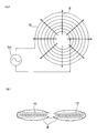
- FIG. 3A and FIG. 3B conceptually show the state of the magnetic flux of the high-frequency magnetic field formed when a high-frequency current is passed through the coil 10.
- the magnetic flux B is generated radially (in the radial direction) from the inner peripheral side to the outer peripheral side of the coil 10 on the surface side of the coil 10 as shown in FIG. 3A, and the coil 10 as shown in FIG.
- the magnetic flux B is generated in a direction orthogonal to the conducting wire of the coil 10 according to the right-handed screw law.
- the direction of the magnetic flux is also reversed depending on the polarity of the high frequency current.
- FIG. 3B shows that the magnetic flux has a start point and an end point, this is for explanation, and as is clear from the Maxwell equation, the magnetic flux is continuous and there is no start point or end point. .
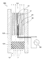
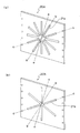
- FIG. 4 (a) is a perspective view of the first heating plate 20 having the slits 21, and FIGS. 4 (b) and 4 (c) show the bb line and cc of FIG. 4 (a), respectively.
- the slit 21 of the first heating plate 20 is not formed, and the magnetic flux generated in the coil 10 reaches the first heating plate 20, and the first heating plate 20 generates an induced current.
- An eddy current flows to inductively heat the first heating plate 20.
- the second heating plate 30 cannot be reached (a part of the magnetic flux may pass through the first heating plate 20).
- a slit 21 is formed in the first heating plate 20, and the magnetic flux generated in the coil 10 reaches the second heating plate 30, and the second heating plate 30 An eddy current flows as the induced current, and the second heating plate 30 is induction-heated.
- a total of four heating plates 20 and 30 including a pair of first heating plates 20 and a pair of second heating plates 30 generate heat by induction heating, and flow paths
- a fluid such as gas or liquid
- the front and back surfaces of the respective heating plates 20 and 30 become heat transfer surfaces, so that heat is transferred to the fluid from a total of eight heat transfer surfaces, and the fluid is heated.
- the coil 10 also generates heat due to Joule heat (so-called copper loss) due to its own resistance, but the inside of the insulating case 12 (that is, the front surface and the back surface of the coil 10) is also configured as a flow path.
- heat can be efficiently transferred to the fluid, and the coil 10 can be sufficiently cooled by the fluid. Even when the coil 10 is completely covered with the insulating case 12, since the outside of the insulating case 12 is a flow path, the heat generated in the coil 10 can be transferred to the fluid through the insulating case 12.
- the 1st heating plate 20 which has the slit 21 concerning this invention consists of a nonmagnetic metal plate
- an induction heating apparatus was produced using the 1st heating plate 20 which consists of a magnetic metal plate.
- An experiment was conducted to confirm the influence of the second heating plate 30 on the temperature increase. That is, instead of the austenitic stainless steel plate SUS304, the induction heating apparatus 1 incorporating the first heating plate 20 provided with the slit 21 in the same manner in the ferritic stainless steel plate SUS430 is operated under the same conditions. Although the plate 20 was induction heated, the second heating plate 30 was not induction heated.
- the first heating plate 20 is preferably composed of a nonmagnetic metal plate rather than a magnetic metal plate.
- the heat generating element described in Patent Document 1 is configured such that a sheet made of SUS447J1 made of ferritic stainless steel having magnetism is laminated so that the whole can be energized by spot welding, it is separated from the coil. Inductive current also flows through the sheet to generate heat, but if each sheet is not energized, only the sheet near the coil generates heat by induction heating, and the sheet away from the coil is not induction heated, so the heat transfer area is increased. I can't do it. In other words, in order to generate heat from the sheet away from the coil, each sheet must be spot-welded so that it can be energized as a whole.
- the first heating plate 20 close to the coil 10 is configured as a non-magnetic metal plate provided with the slit 21, so that the magnetic flux transmitted through the slit 21 is from the coil 10. Even if the first and second heating plates 20 and 30 are not electrically connected, the second heating plate 30 as well as the first heating plate 20 can be connected to the second heating plate 30 that is far away. Induction heating is possible. That is, according to the induction heating apparatus 1 according to the present invention, since a plurality of heating plates 20 and 30 need only be arranged at predetermined positions without using a special manufacturing process such as spot welding, the manufacturing cost is extremely high. It can be kept low.
- FIG. 5 is a cross-sectional view showing a schematic configuration of the hot air generator. 5 may be a hand dryer.
- a hot air generator 100 shown in FIG. 5 includes a duct 103 that fluidly communicates between the air inlet 101 and the jet outlet 102, the induction heating device 1 (FIG. 1) disposed inside the duct 103, a duct, A blower 104 that forms a fluid flow F in the inside 103 and a high-frequency power source 50 are provided.
- the hot air generator 100 has a control circuit (not shown) for controlling the driving conditions of the high-frequency power supply 50.
- the coil 10 of the induction heating apparatus 1 is formed by winding a 0.75 mm diameter enamel wire in a spiral shape to form a disk shape having a diameter of 140 mm, and then a nomex paper (DuPont, registered as a heat-resistant paper on the front and back surfaces). And is laminated in a rectangular case 12 having a planar size of 160 mm ⁇ 150 mm.
- the first heating plate 20 is a non-magnetic stainless steel plate of SUS304 having a planar size of 160 mm ⁇ 150 mm and a thickness of 65 mm ⁇ width 1 mm (eight) extending radially from the center as shown in FIG. ) Slits are separated from each other at an angle of 45 °.
- the second heating plate 30 is a SUS430 magnetic stainless steel plate having a thickness of 2 mm and a planar dimension of 160 mm ⁇ 150 mm.
- the spacer 40 is a 150 mm ⁇ 5 mm ⁇ 3 mm SUS304 nonmagnetic stainless steel member, and has a space of 3 mm between the rectangular case 12 and the first heating plate 20 and between the first and second heating plates 30.
- the rectangular case 12 and the first and second heating plates 20 and 30 are fixed integrally with each other by using any suitable fixing means such as screws.
- the induction heating apparatus 1 according to Embodiment 1 is configured.
- the induction heating apparatus 1 and the duct 103 are designed so that the distance between the second heating plate 30 and the inner wall of the duct 103 is similarly 3 mm.
- the high-frequency power supply 50 that supplies a high-frequency current to the coil 10 will be described later, but may have any form generally used in an induction heating device, and is constituted by, for example, a resonant capacitor and two switching elements. It may be a half-bridge type inverter.
- the hot air generator 100 configured in this manner, when a high frequency current is supplied from the high frequency power supply 50 to the induction heating device 1 and the blower 104 is driven, the air sucked from the air inlet 101 of the blower 104 is converted into the induction heating device. 1 and is discharged from the outlet 102 as warm air.
- the electric energy input to the induction heating device 1 is converted into heat energy by the induction heating device 1, and this heat energy warms the air and also the duct 103 or the blower 104 or the like. Heat is transferred to peripheral parts by convection, conduction, and radiation. Therefore, most of the electric energy input to the induction heating device 1 is finally transferred to the air. Therefore, the temperature of the air discharged from the hot air generator 100 is measured, and the first of the induction heating device 1 is measured. It is difficult to evaluate the heat transfer performance with respect to the first and second heating plates 20 and 30.
- the case 12 and the duct 103 adjacent to the first and second heating plates 20 and 30 are formed using a constituent material having heat resistance or flame retardancy. There is a need. Designing the hot air generator 100 so that some components do not become abnormally high is extremely preferable from the viewpoint of suppressing an increase in manufacturing cost. Therefore, it is preferable that the heat generated from the induction heating device 1 is more uniformly transferred to the first and second heating plates 20 and 30.
- a high frequency current having a frequency of 20 kHz is supplied to the coil 10 with a power of 400 W, and the jet outlet 102 of the blower 104 is controlled to discharge air of 1.1 m 3 / min. , raised the temperature T C of the coil 10 to the intake air temperature (the surface of the conductor), raised the temperature T 1 of the first heating plate 20 (the average of the two), raised the temperature of the second heating plate 30 (the average of the two) T 2, and to a raised temperature T D of the inner surface of the duct 103, respectively to obtain the results as follows.
- the measurement position is a position 3 cm outside the center of the first heating plate 20, and the measurement positions of the coil 10, the second heating plate 30, and the duct 103 are also the first heating plate. This is a position corresponding to the measurement position of the plate 20.
- the first and second heating plates 20 and 30 have substantially the same rising temperature T 1 and T 2 and are almost uniformly induction-heated by the high-frequency current flowing through the coil 10. It was.
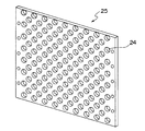
- a hot air generator using a first heating plate 20 in which circular holes 24 are arranged in a grid pattern as shown in FIG. 6 (hereinafter referred to as “perforated heating plate 25”).
- perforated heating plate 25 a hot air generator using a first heating plate 20 in which circular holes 24 are arranged in a grid pattern as shown in FIG. 6
- perforated heating plate 25 the same measurement as described above was performed.
- nonmagnetic stainless steel SUS304 having a thickness of 1 mm and circular holes 24 having a diameter of 8 mm and 6 mm arranged in a grid are prepared and incorporated in the hot air generator 100.
- the opening ratio of the circular holes 24 to the perforated heating plate was about 58% and about 40%, respectively.
- the eight slits 21 having a length of 65 mm and a width of 1 mm extending radially from the center are provided in the first heating plate 20 shown in FIG. is there.
- the second heating plate 30 has a very high temperature regardless of the aperture ratio. Not. That is, the magnetic flux B from the coil 10 does not pass through the first heating plate 20 even if many circular holes 24 are provided, and does not reach the second heating plate 30.
- the second heating plate 30 is the second heating plate 30 even though the aperture ratio due to the slit 21 when the slits 21 are provided in the first heating plate 20 is relatively small at about 2.2%.
- the slit 21 extending in the same direction as the direction of the magnetic flux has an extremely large influence on the effect of transmitting the magnetic flux B as compared with the circular hole 24 since It can be seen that the effect of increasing the heat transfer area according to the invention acts remarkably.
- a nonmagnetic stainless steel SUS304 having a thickness of 1 mm and circular holes 24 having a diameter of 8 mm, 6 mm, and 3 mm arranged in a lattice shape is further added to the perforated heating plate 25 and the length extending radially from the center.
- a device provided with eight slits 21 of 65 mm ⁇ width 1 mm was manufactured, and the same measurement as described above was performed in the hot air generator 100 using this as the first heating plate 20.
- the slit 21 according to the present invention is used, and the aperture ratio of the circular holes 24 is about 58%, about 40%, and about 33% (the perforated heating plate 25 having a circular hole with a hole diameter of 3 mm) 3.
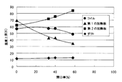
- the coil rising temperature T C the first heating plate rising temperature T 1 , the second heating plate rising temperature T 2 , and the duct surface rising temperature with respect to the intake air temperature of the fluid flow F It was measured T D.
- the aperture ratio does not include the aperture ratio due to the slit 21, and the first heating plate 20 that does not have the circular holes 24 and has only the slits 21 has the aperture ratio of 0%.
- the same measurement was performed (Table 3). And the graph of FIG. 7 was obtained by plotting each rising temperature in each aperture ratio.
- the rising temperature T1 of the first heating plate 20 becomes lower and the rising temperature T2 of the second heating plate 30 becomes higher. Therefore, by controlling the aperture ratio of the circular holes 24 provided in the first heating plate 20, the rising temperatures T 1 and T 2 of the first and second heating plates 20 and 30 can be controlled. Alternatively, the rising temperatures T 1 and T 2 of the first and second heating plates 20 and 30 can be controlled by the number and width of the slits 21 provided in the first heating plate 20. Since the rising temperatures T 1 and T 2 of the first and second heating plates 20 and 30 can be controlled by controlling the aperture ratio of the circular holes 24 provided in the first heating plate 20, However, there is an advantage that the degree of freedom of design increases.
- each aperture ratio, elevated temperature T 2 of the temperature increase T 1, the second heating plate 30 of the rise of the coil with respect to the intake air temperature of the fluid flow F temperature T C, the first heating plate 20, and the duct 103 is a graph plotting the respective measurement results of the temperature increase T D of the surface of the.
- the rising temperatures T 1 and T 2 of the first and second heating plates 20 and 30 are approximately the same, and both the heating plates 20 and 30 are equally induction-heated,
- the rising temperature T C of the coil 10 is higher than the rising temperatures T 1 and T 2 of the first and second heating plates 20 and 30.
- peripheral parts such as the case 12 that accommodates the coil 10 must be formed using a material having a higher heat-resistant temperature. it is preferable to suppress the temperature increase T C of the coil 10.
- the upper end and the lower end of the case 12 including the coil 10 are opened to form a flow path through which the fluid flows also inside the case 12, and the coil 10 is cooled by the fluid, and from the aluminum plate Rather, it is more preferable to configure the first heating plate 20 using a nonmagnetic stainless steel plate.
- the reason for the coil 10 becoming higher temperature is that the resistance of the aluminum plate is smaller than the resistance of the SUS304 stainless steel plate, so that the coil 10 of the induction heating apparatus 1 is used. This is because the resistance component induced in the first heating plate 20 when a high-frequency current is passed through is small, and the ratio of the power consumed by the coil 10 is large.
- the impedance measurement of the induction heating device 1 when the first heating plate 20 is a SUS304 stainless steel plate, about 6 to 7% of the input power is consumed by the coil 10, but in the case of an aluminum plate, About 20% of power is consumed by the coil 10.
- the resistance of the first heating plate 20 may be increased.
- a material having a large volume resistivity may be used or the plate thickness may be reduced.
- the volume resistivity of the SUS304 stainless steel plate at room temperature is 71 ⁇ 10 ⁇ 8 ⁇ m
- the volume resistivity of the aluminum plate is 2.75 ⁇ 10 ⁇ 8 ⁇ m.
- Non-magnetic metal and high volume resistivity materials include nichrome (110 ⁇ 10 ⁇ 8 ⁇ m), chromel (70 to 100 ⁇ 10 ⁇ 8 ⁇ m), constantan (47 to 51 ⁇ 10 ⁇ 8 ⁇ m), although these may be used, austenitic stainless steel is optimal as a material that can be obtained at low cost.
- Austenitic stainless steel has a volume resistivity of 71 to 94 ⁇ 10 ⁇ 8 ⁇ m at room temperature.
- the plate thickness is reduced, the resistance of the aluminum plate can be increased even with a material having a small volume resistivity such as aluminum.
- the plate thickness is 0.1 mm or less, the resistance of the aluminum plate is sufficiently large and the power consumed by the coil 10 can be sufficiently reduced.
- the plate thickness is thin, it is easily deformed by heat generated by induction heating. Become. Therefore, a design that allows for deformation of the aluminum plate is required.
- the use of aluminum which is cheaper than stainless steel, is advantageous in terms of cost reduction. Even if the plate thickness is set to 0.1 mm or more and the power consumed by the coil 10 is slightly increased, the periphery of the coil 10 is a flow path. This is possible because it is cooled.
- the first heating plate 20 is a SUS304 nonmagnetic stainless steel plate having a thickness of 160 mm ⁇ 150 mm and a SUS304 thickness of 65 mm ⁇ 1 mm wide extending radially from the center as shown in FIG.
- a plurality of (eight) slits are formed so as to be separated from each other at an angle of 45 °, and the circular hole 24 is not provided. Table 4 shows the measurement results.
- the specific geometrical values have been described, but the dimensions of the heating plates 20 and 30, the coil 10, and the spacer 40 are not limited to this. If a similar structure is realized, a space serving as the flow path P may be formed without using the spacer 40 and without using the spacer 40 by bending the ends of the heating plates 20 and 30. In addition, although two each of the first heating plate 20 and the second heating plate 30 are provided on both surfaces of the coil 10, the first heating plate 20 and the second heating plate 30 are provided on one surface of the coil 10. May be.
- Embodiment 2 of the induction heating apparatus according to the present invention will be described with reference to FIGS.
- the induction heating device 2 according to the second embodiment has the same configuration as that of the first embodiment except that a plurality of first heating plates 20 are provided on both sides of the coil 10. Description is omitted.
- FIG. 9 is a perspective view showing the induction heating device 2 according to the second embodiment of the present invention.
- the induction heating device 2 of the second embodiment includes a first heating plate 20a made of nonmagnetic austenitic stainless steel disposed on both sides of a case 12 that houses the coil 10 (FIG. 10 (a)), and on the outside thereof. It has another 1st heating plate 20b which consists of the material of the equivalent nonmagnetic material arrange
- the first heating plate 20a closer to the coil 10 is formed so that twelve slits of 65 mm in length and 1 mm in width extending radially from the center are separated from each other at an angle of 30 °.
- the first heating plate 20b disposed further away from the coil 10 has six slits of 65 mm in length and 1 mm in width extending radially from the center as shown in FIG. It is formed so as to be separated by an angle of °.
- the slit 21b of the first heating plate 20b arranged on the outer side is formed so as to overlap (superimpose) the slit 21a of the first heating plate 20a arranged on the inner side when viewed from the direction perpendicular to the first heating plate 20a. ing.
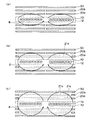
- FIGS. 10 (a) and 10 (b) are cross-sectional views of the induction heating device 2 as viewed from the aa, bb, and cc lines in FIGS. 10 (a) and 10 (b). It is.
- the first heating plate 20 a disposed on the inner side cannot transmit the magnetic flux B in the absence of a slit and is induction-heated by the magnetic flux from the coil 10.
- the first heating plate 20b arranged outside cannot transmit the magnetic flux B in the absence of the slit 21b, and the slit 21a of the first heating plate 20a arranged inside. Inductive heating is performed by the magnetic flux B transmitted through the.
- the second heating plate 30 is induction-heated by the magnetic flux transmitted through the slits 21a, 21b of both the first heating plates 20a, 20b.
- the induction heating apparatus 2 configured in this way, by providing the slits 21a and 21b in the first heating plates 20a and 20b, all the heating plates 20a, 20b and 30 can be induction-heated, and the heat transfer area Can be further increased. Further, by making the width of the slit 21a of the first heating plate 20a arranged on the inner side wider than the width of the slit 21b provided on the first heating plate 20b arranged on the outer side, the magnetic flux is surely applied to the second heating plate 30. You may make it reach.
- the same number of slits 21 are provided on the first heating plate 20a arranged on the inner side and the first heating plate 20b arranged on the outer side so as to overlap each other, and the width of the former slit 21a is formed wider than that of the latter slit 21b.
- a part of the magnetic flux B transmitted through the slit 21a of the first heating plate 20a induces and heats the first heating plate 20b, and the remaining magnetic flux B passes through the first heating plate 20b and passes through the second heating plate 30. May be induction heated.
- the induction heating device 2 having the two first heating plates 20a and 20b arranged inside and outside the coil 10 and the second heating plate 30 has been described. Since it reaches 10 to several centimeters, more first heating plates 20 may be provided.
- FIG. 12 is a perspective view showing an induction heating device 2 having four first heating plates 20 on both sides of the coil 10 and a second heating plate 30 on the outside thereof.
- a larger number of first heating plates 20 can be arranged to realize a larger heat transfer area.
- the first heating plate 20 disposed on the outer side is farther away from the coil 10, so that the magnetic flux from the coil 10 becomes weaker and the induction heating becomes difficult. . Therefore, as shown in FIG. 13, a plurality of first heating plates 20 may be induction-heated using a plurality of coils 10.
- the width of the slit 21 so that each of the first heating plates 20 is heated evenly, but the plurality of first heating plates so that the slit widths are different (different shapes). Since the formation of the plate 20 causes high costs, it is preferable to use the induction heating device 2 by using the first heating plate 20 having the same shape as much as possible in order to manufacture the plate 20 at a low cost.
- the rising temperature (T 1 ) varies depending on the distance from the coil 10 to each of the first heating plates 20, but the heated fluid generates the above-described hot air.
- the fluid that is agitated inside the main body device such as the device 100 and ejected from the main body device has a uniform temperature, and there is often no problem in actual use.
- the second heating plate 30 is arranged on the outermost side.
- the first heating plate 20 is used. It may be replaced.
- Embodiment 3 of the induction heating apparatus according to the present invention will be described with reference to FIGS.
- the induction heating device 3 of the third embodiment is the same as that of the second embodiment except that the first heating plate 20a and the second heating plate 30 disposed inside are provided with undulations (unevenness) to increase the heat transfer area. Since the configuration is the same as that in FIG.
- the induction heating device 3 shown in FIGS. 14 and 15 has a case 12 that houses the coil 10 and a nonmagnetic metal plate (for example, a metal plate made of SUS304) bent into a corrugated shape (provided with irregularities).
- a nonmagnetic metal plate for example, a metal plate made of SUS304
- a second heating plate 30 provided with continuous undulations by bending the metal plate) into a corrugated shape.
- the first heating plates 20a and 20b and the second heating plate 30 are induction-heated as in the first and second embodiments.
- the first heating plate 20a and the second heating plate 30 arranged inside are formed in a continuous corrugated shape, and compared with a flat metal plate, the contact area with the fluid (transmission) The heat transfer effect can be improved because the heat area can be increased.
- the first heating plate 20a having a corrugated shape disposed inside and the second heating plate 30 having the corrugated shape fix the coil 10.
- the induction heating device 3 does not require a spacer as a separate member in order to form the flow path.
- the flat metal plate When the temperature of the corrugated metal plate rises due to heating, the flat metal plate may thermally expand and warp larger than the corrugated metal plate in its parallel plane, making it difficult to maintain the flow path in a stable shape. Accordingly, the flat support plate 11, the first heating plates 20a and 20b, and the second heating plate 30 that fix the coil 10 are not fixed via the spacer 40, as shown in FIGS. It is desirable to construct so that it is simply laminated. More preferably, the first heating plate 20b having a flat plate is formed using an insulator that does not easily thermally expand so that the first heating plate 20a and the second heating plate 30 that are corrugated metal plates do not warp. May be. However, the flat first heating plate 20b is preferably formed using a nonmagnetic metal material rather than an insulator because the heat transfer area can be increased.
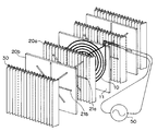
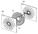
- FIG. 16 is a perspective view showing an induction heating device 4 according to Embodiment 4 of the present invention.
- the induction heating device 4 according to the fourth embodiment generally includes a cylindrical case 32 made of an insulator such as ceramics, a cylindrical coil 18 wound around the outside thereof, and a predetermined interval inside the cylindrical case 32. And a plurality of heating plates 20 made of a non-magnetic metal plate (for example, a metal plate made of SUS304).
- a high frequency current is supplied to the cylindrical coil 18 from a high frequency power source (not shown), a high frequency magnetic field is generated in the longitudinal direction of the cylindrical case 32 (up and down direction in FIG. 16).
- Each of the plurality of heating plates 20 is provided with a plurality of slits 21 extending in the same direction as the direction of the magnetic flux B of the high frequency magnetic field formed by the cylindrical coil 18 (the longitudinal direction of the cylindrical case 32). At this time, a part of the magnetic flux B of the high frequency magnetic field from the cylindrical coil 18 induction-heats the heating plate 20 closest to the cylindrical coil 18, but a part thereof passes through the slit 21 provided on the heating plate 20. Then, it reaches the heating plate 20 on the inner side, and this is induction-heated.
- the heating plate 20 is most preferably austenitic stainless steel SUS304 similar to the first heating plate 20 described in the first embodiment.
- the heating plate 20 is a flat plate.
- the heating plate 20 bent in a waveform may be provided with a slit 21.
- the cylindrical case 32 is not limited to a cylindrical cross section, and may be a hollow body having a rectangular cross section.
- Induction heating apparatuses 1 to 3 according to Embodiments 1 to 3 are configured by a combination of a flat coil 10 and a plurality of flat heating plates 20 and 30, so that fluid heating is thin and has a large heat transfer area. Induction heating apparatus can be obtained. Such an induction heating apparatus can be used as a heat source for various apparatuses.
- a hand drying apparatus 200 incorporating the induction heating apparatus 1 according to Embodiment 1 will be described below.
- a typical hand dryer using a sheath heater is described in, for example, Japanese Patent Application Laid-Open No. 10-75915, and the disclosure thereof is integrated here as a single unit for reference.
- FIG. 17 is a side cross-sectional view showing the hand dryer 200 according to the fifth embodiment.
- the hand dryer 200 generally includes a housing 202, a blower 204 that is a high-pressure air generator that generates high-pressure air, and a power supply device 250.
- the housing 202 includes a manual insertion portion 206, an intake port 208 for taking in ambient air, jet ports (spout nozzles) 212a and 212b for jetting air heated by the induction heating device 1, and an intake port 208.
- the jet outlets 210a and 210b are in fluid communication with each other and have a front side duct 203a provided on the front side of the hand insertion portion 206 and a back side duct 203b provided on the back side.
- a front side induction heating device 1a and a back side induction heating device 1b similar to the induction heating device 1 of the first embodiment are disposed inside the front side duct 203a and the back side duct 203b, respectively.
- the induction heating devices 1a and 1b are electrically connected to the power supply device 250 by electric wirings 210a and 210b, and a high frequency current is supplied from the power supply device 250 to the induction heating devices 1a and 1b.
- the power supply device 250 has a control circuit (not shown) for controlling the blower 204 and the induction heating devices 1a and 1b.
- the hand dryer 200 configured as described above, when the blower 204 is operated, air is sucked from the air inlet 208, and the front side induction heating device 1a and the back side induction heating device 1b heat the air, and then the heated high pressure and high speed
- the air jet F is ejected from the front side nozzle 212a and the back side nozzle 212b.
- the air jet (warm air) F ejected from the front side nozzle 212a and the back side nozzle 212b is placed in the hand.
- the attached water droplets can be blown away to quickly dry the hands.
- the hand insertion unit 206 of such a hand drying apparatus 200 has a width that allows both hands to be inserted in the vertical direction (depth direction) of the paper surface of FIG. 17 and has a depth that allows insertion to the wrist in the vertical direction.
- the manual insertion part 206 has a space
- the distance between the left and right directions of the hand insertion portion 206 is small. Therefore, in order to increase the distance between the hand insertion portions 206 of the hand dryer 200 in the left-right direction of FIG.
- the front side duct 203a and the rear side duct 203b are provided inside. It is necessary to design the arranged induction heating devices 1a and 1b as thin as possible, and the induction heating device of the present invention is extremely suitable.
- the thickness of the coil 10 is 2 mm
- the space (flow path) between the coil 10 and the first heating plate 20 is 3 mm
- the thickness of the first heating plate 20 is Since 1 mm
- the space (flow path) between the first and second heating plates 30 is 3 mm
- the thickness of the second heating plate is 2 mm
- the thickness of the induction heating device 1 as a whole is 20 mm.
- the depth of the duct 203 is 26 mm. If the space (flow path) through which the airflow passes is 2 mm, the depth of the duct 203 is 20 mm.
- the front side induction heating device 1a and the back side induction heating device 1b may be individually controlled so that the temperatures of the air ejected from the front side nozzle 212a and the back side nozzle 212b are different from each other.
- the user usually inserts the hand into the hand insertion portion 206 so that the palm faces the front side nozzle 212a, so the warm air blown from the front side nozzle 212a hits the palm and is blown from the back side nozzle 212b. Hot air hits the back of the hand.
- a hand is washed, more water droplets adhere to the palm than the back of the hand.
- the temperature of the air ejected from the front side nozzle 212a and the back side nozzle 212b is higher than the temperature of the air ejected from the back side nozzle 212b.
- two independent power supply devices 250 that supply high-frequency current to the front side induction heating device 1a so that the power supplied to the front side induction heating device 1b is larger than the power supplied to the back side induction heating device 1b. May be provided and controlled individually.
- the hand dryer 200 may be configured so that the user can adjust the temperature of the air ejected from the front nozzle 212a and the back nozzle 212b.
- the two power supply devices 250 for the front side induction heating device 1a and the back side induction heating device 1b and controlling them individually increases the manufacturing cost of the hand drying device 200.
- the number of turns of the former coil 10 is set to the latter.
- the temperature of the air ejected from the front side nozzle 212a is ejected from the rear side nozzle 212b by reducing the number of turns of the former coil 10 than the latter.
- the hand dryer 200 may be configured to be higher than the temperature of the air.
- FIG. 18 is a block diagram showing a circuit configuration of a power supply apparatus 250 that supplies different electric power to the front side induction heating apparatus 1a and the back side induction heating apparatus 1b.
- the power supply apparatus 250 includes a half bridge circuit 254 in which switching elements 252a and 252b such as IGBTs are connected in series.
- a DC voltage is supplied from the DC power supply 256 to the half bridge circuit 254, and is switched by the switching elements 252 a and 252 b of the half bridge circuit 254, and a predetermined rectangular wave voltage is output to the output stage of the half bridge circuit 254.
- the switching elements 252 a and 252 b of the half bridge circuit are driven by the half bridge driver 258, and the half bridge driver 258 is controlled by the control unit 260.
- a capacitor 262 is connected between the DC power supply 256 and the half bridge circuit 254, and the current is smoothed as necessary and supplied to the half bridge circuit 254.
- a front-side induction heating device 1a having a resonance capacitor C1 connected in series and a back-side induction heating device 1b having a resonance capacitor C2 connected in series are connected in parallel to the output terminal of the half bridge circuit 254. .
- the inductances of the front side induction heating device 1a and the back side induction heating device 1b may be different, but will be described below assuming that they are the same.
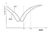
- the power supply device 250 shown in FIG. 18 includes two resonance circuits, that is, a front-side resonance circuit RC1 including a front-side induction heating device 1a and a resonance capacitor C1 connected in series, and a back-side induction heating device 1b and a resonance capacitor connected in series. And a back side resonance circuit RC2 by C2.
- the capacitances of the resonance capacitors C1 and C2 are different from each other, and FIG.
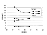
- FIG. 19 is a graph showing the frequency dependence of the impedances of the front-side resonance circuit RC1 and the back-side resonance circuit RC2.
- the minimum value of each impedance is the resonance frequency of each resonance circuit.
- the impedance of the front-side resonance circuit RC1 is similarly smaller than the impedance of the back-side resonance circuit RC2, but the difference between the two impedances Is smaller than when the frequency of the rectangular wave voltage is f1. That is, by adjusting the frequency of the rectangular wave voltage output from the half-bridge circuit 254 and controlling the duty ratio thereof, the power consumption of one induction heating device is kept constant while the other induction heating device is kept constant. Power consumption can be controlled.
- the induction heating apparatus provided with a plurality of heating plates on both sides of the coil has been described.
- the induction has a simpler configuration in which a single heating body is disposed on each side of the coil.
- the heating device will be described below.
- FIG. 20 is a perspective view showing the induction heating device 6 according to Embodiment 6 of the present invention
- FIG. 21 is an exploded perspective view of the induction heating device 6 shown in FIG.
- the induction heating device 6 according to the sixth embodiment includes the same coil 10 as that of the first embodiment and the heating plate 20 that is arranged at a predetermined interval with a spacer 40 interposed between the coil 10 and the heating plate.
- a flow path P is formed between the
- the heating plate 20 is preferably a magnetic metal such as SUS430 of ferritic stainless steel, but may be a nonmagnetic metal such as SUS304 of austenitic stainless steel.
- the heating plate 20 is induction heated.
- Heat is transferred from the heating plate 20 to the air (air is heated) by flowing a fluid such as air through the flow path P between the coil 10 and the heating plate 20.
- a fluid such as air
- the heat transfer area is doubled compared to the case where the flow path P is not provided between the coil 10 and the heating plate 20. Can be increased.
- it is preferable that the heat generated in the coil 10 is also directly transferred to the air and the coil 10 is similarly exposed to the air flow (cooled by air). At this time, when the coil 10 is exposed to an air flow, the insulating coating of the coil 10 is easily damaged by dust in the air. Therefore, the coil 10 is preferably covered with an insulator such as resin, glass, or ceramic.
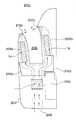
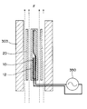
- FIG. 22 is a side cross-sectional view showing a hand dryer 300 incorporating the induction heating device 6 of FIG.
- a hand dryer 300 shown in FIG. 22 is substantially the same as the hand dryer 200 shown in FIG. 17 of the fifth embodiment.
- FIG. 23 is an enlarged cross-sectional view showing a portion surrounded by a thick broken line A in FIG. 22, which is substantially the same as the induction heating device 6 in FIG. 20.
- a predetermined interval is also provided between the heating plate 20 and the duct 303, and a flow path P is formed between the two, and a total of four flow paths P are formed. ing.
- the induction heating device 6 induction-heats the two heating plates 20 with one coil 10, and both the front and back surfaces of the two heating plates 20 serve as heat transfer surfaces (a total of four surfaces). Configured to work. Therefore, since a larger number of heat transfer surfaces can be realized by using a limited number of coils 10 and heating plates 20, it is possible to manufacture a small induction heating device 6 with higher heat transfer efficiency and lower cost. .
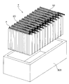
- FIG. 24 is a perspective view of a plurality of induction heating devices 6 shown in FIG. 20 arranged in parallel via spacers 41, and FIG. 25 is parallel to a horizontal plane (a plane perpendicular to the flow path P). It is sectional drawing when cut
- the induction heating device shown in FIG. 20 configured as described above, the same operation and effect as the induction heating device 6 shown in FIG. 20 can be realized, and since it has a large number of heat transfer surfaces, it is more efficient. Heat can be transferred to the air and warm air can be obtained.
- the plurality of induction heating devices 6 shown in FIG. 20 are arranged so as to be separated from each other by using the spacers 41.
- the present invention is not limited to this, and the outside is provided with grooves provided at predetermined intervals.
- Each of the plurality of induction heating devices 6 may be disposed on a frame (not shown) so as to be fitted in the groove portion and separated from each other.
- FIG. 26 is an exploded perspective view showing the induction heating device 7 according to the seventh embodiment of the present invention
- FIG. 27 is a partial exploded perspective view of the induction heating device 7 of FIG.
- the coil 10 of the induction heating device 7 is substantially the same as that of the sixth embodiment
- the heating plate 20 of the induction heating device 7 is not flat and is formed by being bent into a waveform. Between the coil 10 and the heating plate 20, a flow path P is formed between the mountains (between adjacent peaks) without providing a spacer.
- FIG. 28 is a cross-sectional view when the induction heating device 7 shown in FIGS. 26 and 27 is cut along a plane parallel to a horizontal plane (a plane orthogonal to the flow path P). In the partial region L in the left half of FIG.
- the ridges of the respective heating plates 20 are arranged so as to coincide (facing) with each other.
- the plurality of heating plates 20 may be arranged at arbitrary positions as long as the direction of the flow path P is constant.
- the winding direction of each of the plurality of coils 10 is preferably the same. This is because leakage magnetic flux generated due to a space serving as the flow path P between the coil 10 and the heating plate 20 weakens each other's magnetic flux. For example, if the winding direction of one of the plurality of coils 10 is opposite to the other, the temperature rise of the coil 10 itself is greater when the same power is input than when the same direction is used. That is, Joule heat from the coil 10 increased. Also in the present embodiment, air is passed through the flow path P between the coil 10 and the heating plate 20, and the heat from the coil 10 is also transferred to the air, but the surface of the coil 10 is covered with an insulator. Therefore, in order to more efficiently transfer heat to the air, it is preferable to increase the ratio of induction heating from the heating plate 20 to Joule heat from the coil 10 with respect to input power.
- the heat transfer area can be increased as compared with the flat plate, and the heat transfer efficiency to the air can be improved.
- FIG. 29 is a similar cross-sectional view showing a modification of the induction heating device 7 shown in FIG.
- a single heating plate 20 is disposed between adjacent coils 10
- two heating plates 20 and a partition plate 26 are provided.
- the partition plate 26 is sandwiched between two corrugated heating plates 20 and maintains a distance therebetween, and is preferably made of a metal plate, but is made of an insulating material such as glass, ceramics, or resin. Also good. Even if the partition plate 26 is a metal plate, the heat generated by induction heating is small, but rather, heat is easily transferred from the corrugated heating plate 20 that has been induction heated.
- the partition plate 26 constitutes a part of the flow path P, it functions as a heat transfer surface to the air. Therefore, the induction heating apparatus shown in FIG. 29 can be induction-heated (increase the heat transfer surface more) with a smaller number of coils 20 than the apparatus shown in FIG. In addition, an induction heating device with high transmission efficiency can be realized.
- the coil 10 is described as being housed in the insulating case 12 made of an insulating material such as resin or ceramics.
- the coil 10 according to the present embodiment is housed in the coil case 14 made of a metal material. Since it has the same configuration as that of the above-described embodiment except for the point, it can be replaced with an arbitrary coil used in the induction heating device of the above-described embodiment. That is, the coil of the eighth embodiment can be applied not only to the sixth and seventh embodiments but also to all the coils according to the first to seventh embodiments.
- FIGS. 30 is an exploded perspective view showing the coil 10 according to the eighth embodiment
- FIG. 31 is a cross-sectional view of the coil shown in FIG. 30 taken along a plane parallel to the horizontal plane.
- the coil 10 according to the eighth embodiment is formed by winding a conductive wire such as an enamel wire in a spiral shape, and is sandwiched between coil cases 14a and 14b made of a pair of metal materials (FIG. 30) and fixed integrally (FIG. 31).
- the coil cases 14a and 14b are preferably made of a non-magnetic metal such as aluminum and have a plurality of slits 21 extending radially from the vicinity of the center of the coil 10 as shown in FIG.
- the magnetic flux generated in the coil 10 passes through the coil cases 14a and 14b, and the heating plate disposed away from the coil 10 can be induction-heated.
- the coil cases 14a and 14b are similarly induction-heated by the magnetic flux from the coil 10, but the heat generated in the coil cases 14a and 14b is suppressed by increasing the number of slits 21 or increasing the width thereof. be able to.
- the coil cases 14a and 14b according to this embodiment are effectively used as a heat transfer surface for heating the fluid.
- an insulating sheet (not shown) made of an insulating material such as resin may be disposed between the coil 10 and the coil cases 14a and 14b.
- the slit 21 may be the same as the existence of a slit for the magnetic flux.
- the coil 10 by disposing the coil 10 in the metal coil cases 14a and 14b, the substantial entire surface of the coil 10 is protected from dust contained in the fluid.
- the coil 10 can be prevented from being deteriorated due to wear due to dust, and the coil 10 having a longer life and higher reliability can be realized.
Abstract
An induction heating apparatus has a coil, one or more first heating panels made of nonmagnetic conductors and each forming a channel between the coil and itself, second heating panels made of magnetic conductors and each forming a channel between each first heating panel and itself, and a high-frequency power supply for supplying a high-frequency current to the coil. The first heating panels have slits extending substantially in the same direction as those of the magnetic fluxes occurring at the coil. Thus, a heat transmission area is increased by a simple structure to realize the induction heating apparatus capable of efficiently heating a fluid such as a gas, and a liquid.
Description
本願発明は、誘導加熱を利用して気体や液体などの流体を加熱する誘導加熱装置に関するものである。
The present invention relates to an induction heating apparatus that heats a fluid such as a gas or a liquid using induction heating.
誘導加熱により金属を加熱し、加熱された金属に接する気体や液体などの流体を加熱する誘導加熱装置がいくつか提案されている。このような誘導加熱装置においては、流体と接する金属表面が伝熱面となるので、流体への効率的な熱伝達を実現するために、伝熱面の面積を極力大きくするように構成されていた。
Several induction heating apparatuses that heat a metal by induction heating and heat a fluid such as a gas or a liquid in contact with the heated metal have been proposed. In such an induction heating device, the metal surface in contact with the fluid becomes the heat transfer surface, and therefore, in order to realize efficient heat transfer to the fluid, the area of the heat transfer surface is configured to be as large as possible. It was.
例えば特許文献1に記載の誘導加熱装置では、セラミックなどの非磁性体材料からなる筒状ケースの外周にリッツ線などの導線を巻回してコイルを形成し、筒状ケースの内側に発熱体を収納し、コイルに高周波電流を流すことによって発熱体を誘導加熱し、発熱体を収納したケース内側に流体を通すことによって流体を加熱している(特許文献1,図1)。発熱体は、磁性を有するフェライト系ステンレス鋼のJIS(Japanese Industrial Standard)規格で規定されたSUS447J1からなる平板状の第1シートと波形状の第2シートを交互に積層して形成されることで伝熱面の面積を大きくするよう構成されている(図2)。第1シートおよび第2シートはスポット溶接で溶着されて電気的に導通されている。また第2シートの表面には流体の乱流を生じさせるための孔が設けられている。このように構成された誘導加熱装置において、コイルに高周波電流を流すと、シート材が空間を有するように且つ電気的に導通可能に積層され、周辺部に沿った電流より前記周辺部を横切る電流の方が流れやすい形状に形成されているので、伝熱面積を確保でき、ケース内側の中央部の発熱体が周辺部よりも多く発熱する。ケース内を通過する流体は周辺部より中央部で流れやすいため、中央部で発熱する発熱体により均一に加熱される。
For example, in the induction heating device described in Patent Document 1, a coil is formed by winding a lead wire such as a litz wire around the outer periphery of a cylindrical case made of a non-magnetic material such as ceramic, and a heating element is provided inside the cylindrical case. The heating element is inductively heated by flowing a high-frequency current through the coil, and the fluid is heated by passing the fluid through the inside of the case in which the heating element is stored (Patent Document 1, FIG. 1). The heating element is formed by alternately laminating a flat first sheet and a corrugated second sheet made of SUS447J1 defined in JIS (Japanese Industrial Standard) standard of ferritic stainless steel having magnetism. It is comprised so that the area of a heat-transfer surface may be enlarged (FIG. 2). The first sheet and the second sheet are welded by spot welding and are electrically connected. The surface of the second sheet is provided with holes for generating a turbulent fluid flow. In the induction heating apparatus configured as described above, when a high-frequency current is passed through the coil, the sheet material is laminated so as to have a space and can be electrically conducted, and the current crossing the peripheral portion from the current along the peripheral portion. Is formed in a shape that facilitates flow, so that a heat transfer area can be secured, and the heating element in the central part inside the case generates more heat than the peripheral part. Since the fluid passing through the case flows more easily in the central portion than in the peripheral portion, it is uniformly heated by the heating element that generates heat in the central portion.
一方、流体を加熱するための誘導加熱装置ではないが、例えば特許文献2において、調理を目的として金属製の鍋を誘導加熱によって加熱する誘導加熱装置が開示されている。このような調理目的の誘導加熱装置にあっては、鍋底面の温度を均一にするため、あるいはアルミニウムや銅など電気伝導度の大きい材質からなる鍋を誘導加熱によって加熱するときに生じる浮力を低減するために誘導加熱用のコイルと鍋の間にアルミニウムや銅からなる電気伝導体を設けることが知られている。
On the other hand, although not an induction heating device for heating a fluid, for example, Patent Document 2 discloses an induction heating device that heats a metal pan by induction heating for the purpose of cooking. In such an induction heating apparatus for cooking purposes, the buoyancy generated when a pan made of a material having a high electrical conductivity such as aluminum or copper is heated by induction heating in order to make the temperature at the bottom of the pan uniform or reduced. In order to do this, it is known to provide an electric conductor made of aluminum or copper between the induction heating coil and the pan.
特許文献2に記載の誘導加熱装置では、誘導加熱用のコイルと被加熱物であるSUS系の磁性容器の間に、中心孔部から周縁部方向に6つのスリット部を放射状に形成した導電板を用いている。スリット部の一つは導電板の外周縁と結ばれている。このような構成において誘導加熱用のコイルに高周波電流を流すと、導電板を周回する方向に誘導電流が流れるが、誘導電流は外周縁と中心孔を結ぶスリット部で遮断されて、誘導加熱用コイルに流れる高周波電流と同方向に向きを変え、中心孔および外周縁と結ばれていないスリットに沿って流れる。この結果、導電板の中心付近の誘導電流は誘導加熱用のコイルに流れる高周波電流と同方向に流れるため、導電板の中心付近の磁界を強め、被加熱物の底面各部における温度差を小さくする。
In the induction heating device described in Patent Document 2, a conductive plate in which six slits are radially formed from the center hole to the peripheral part between a coil for induction heating and a SUS-based magnetic container that is an object to be heated. Is used. One of the slit portions is connected to the outer peripheral edge of the conductive plate. In such a configuration, when a high-frequency current is passed through the induction heating coil, the induction current flows in the direction around the conductive plate. However, the induction current is blocked by the slit connecting the outer peripheral edge and the center hole, and is used for induction heating. The direction is changed in the same direction as the high-frequency current flowing in the coil, and flows along a slit that is not connected to the center hole and the outer peripheral edge. As a result, since the induction current near the center of the conductive plate flows in the same direction as the high-frequency current flowing through the induction heating coil, the magnetic field near the center of the conductive plate is strengthened, and the temperature difference in each part of the bottom surface of the heated object is reduced. .
また、例えば特許文献3には、調理を目的としてアルミニウムや銅あるいはこれらと同等以上の電気伝導率を有する低透磁率材料からなる被加熱物を誘導加熱する誘導加熱装置が開示されている。この誘導加熱装置は、誘導加熱用の加熱コイルと被加熱物の間にアルミニウムなどの電気導体が設けられている。このような誘導加熱装置では加熱コイルから発生する磁界は、電気導体と被加熱物に鎖交するため、両者に誘導電流が発生し、電気導体に誘導された誘導電流の発生する磁界と被加熱物に誘導された電流の発生する磁界の重畳磁界が加熱コイルの発生する磁界の変化を妨げるように電気導体および被加熱物に誘導電流が流れる。つまり、被加熱物に誘導される電流の分布が、電気導体に誘導電流が発生することにより変わることになるので、この電流分布の変化で加熱コイルの等価直列抵抗が大きくなり、同一出力を得る場合の加熱コイルに流す電流値を小さくすることができ、被加熱物に作用する浮力が低減するとともに、電気導体が被加熱物に働く浮力の一部を分担することで被加熱物に作用する浮力を低減している。また電気導体は加熱コイル電流の流れる方向と平行に周回して流れる誘導電流の分布を制限するために、電気導体の一部に切り欠き、開口、スリットが設けられており、電気導体の発熱量を抑制し、被加熱物を加熱している。但し、鉄系の被加熱物の場合には電気導体を挿入することにより、加熱コイルの等価直列抵抗を大きくするという作用はほとんど得られない。
Further, for example, Patent Document 3 discloses an induction heating device that induction-heats an object to be heated made of aluminum, copper, or a low magnetic permeability material having an electric conductivity equal to or higher than that for cooking. In this induction heating apparatus, an electric conductor such as aluminum is provided between a heating coil for induction heating and an object to be heated. In such an induction heating apparatus, since the magnetic field generated from the heating coil is linked to the electric conductor and the object to be heated, an induction current is generated in both, and the magnetic field generated by the induction current induced in the electric conductor and the object to be heated are heated. An induced current flows through the electric conductor and the object to be heated so that a superimposed magnetic field of the magnetic field generated by the current induced in the object prevents a change in the magnetic field generated by the heating coil. In other words, since the distribution of current induced in the object to be heated changes due to the generation of induced current in the electrical conductor, the change in the current distribution increases the equivalent series resistance of the heating coil and obtains the same output. In this case, the current value flowing through the heating coil can be reduced, the buoyancy acting on the object to be heated is reduced, and the electric conductor acts on the object to be heated by sharing a part of the buoyancy acting on the object to be heated. The buoyancy is reduced. In addition, in order to limit the distribution of the induced current flowing around the electric conductor in parallel with the direction in which the heating coil current flows, a cutout, an opening, and a slit are provided in the electric conductor, and the amount of heat generated by the electric conductor Is suppressed and the object to be heated is heated. However, in the case of an iron-based object to be heated, an effect of increasing the equivalent series resistance of the heating coil by inserting an electric conductor is hardly obtained.
このような特許文献1に示された誘導加熱装置にあっては、筒状ケースの内側に平板状および波形状の磁性を有するフェライト系ステンレス鋼のシートを積層して収納しているため、これらのステンレス鋼シートを加熱することで伝熱面積を大きくすることができるが、誘導電流がステンレス鋼シートを流れるようにするため、平板状シートと波形状シートをスポット溶接などで溶着して電気的に導通させる必要があり、その結果、多数のステンレス鋼シートをスポット溶接するための製造コストが増大し、スポット溶接部を確実に導通させなければならず、信頼性維持に要するコストも増大するという問題点があった。
In such an induction heating device shown in Patent Document 1, since a sheet of ferritic stainless steel having flat and corrugated magnetism is laminated and stored inside the cylindrical case, these The heat transfer area can be increased by heating the stainless steel sheet, but in order to cause the induced current to flow through the stainless steel sheet, the flat sheet and the corrugated sheet are welded by spot welding etc. As a result, the manufacturing cost for spot-welding a large number of stainless steel sheets increases, the spot-welded part must be reliably conducted, and the cost required for maintaining reliability also increases. There was a problem.
一方、特許文献2あるいは3に示された誘導加熱装置にあっては、そもそも気体や液体などの流体を加熱するために設計された構造ではないため、流体を効率よく加熱することはできない。また、仮に流体加熱に用いたとしても誘導加熱用のコイルと被加熱物の間に設けられた電気導体の発熱量をできるだけ小さく抑制し、被加熱物の温度分布を均一化したり、効率よく加熱するために電気導体にスリットを設けたものであるため、流体加熱のための伝熱面積という点では主とした伝熱面は鍋底などの被加熱物であり、電気導体は伝熱面としてほとんど寄与するものではない。
On the other hand, the induction heating device disclosed in Patent Document 2 or 3 is not designed to heat a fluid such as a gas or a liquid in the first place, and therefore cannot efficiently heat the fluid. Also, even if it is used for fluid heating, the amount of heat generated by the electrical conductor provided between the coil for induction heating and the object to be heated is suppressed as small as possible, and the temperature distribution of the object to be heated is made uniform or efficiently heated. In order to do this, the electrical conductor is provided with slits, so in terms of the heat transfer area for fluid heating, the main heat transfer surface is a heated object such as a pan bottom, and the electric conductor is almost the heat transfer surface. It does not contribute.
本願発明は、上記のような問題点を解決するためになされたものであり、簡単な構造で伝熱面積を増大させ、気体や液体などの流体を効率よく加熱することができる誘導加熱装置を実現することを目的としている。
The present invention has been made to solve the above-described problems, and an induction heating apparatus that can increase the heat transfer area with a simple structure and efficiently heat a fluid such as a gas or a liquid. It is intended to be realized.
本願発明に係る実施の形態による誘導加熱装置は、コイルと、非磁性導電体からなり、前記コイルとの間に流路を形成する少なくとも1つの第1の加熱板と、導電体からなり、前記第1の加熱板との間に流路を形成する第2の加熱板と、前記コイルに高周波電流を供給する高周波電源とを有し、前記第1の加熱板はコイルによって生じる磁束の方向と実質的に同じ方向に延びるスリットを有するものである。
An induction heating apparatus according to an embodiment of the present invention includes a coil and a nonmagnetic conductor, and includes at least one first heating plate that forms a flow path between the coil and the conductor, A second heating plate that forms a flow path between the first heating plate and a high-frequency power source that supplies a high-frequency current to the coil, wherein the first heating plate has a direction of magnetic flux generated by the coil; It has a slit extending in substantially the same direction.
本願発明によれば、第1の加熱板のスリットを透過した磁束が、その外側に配置された第2の加熱板にも届くので、全ての加熱板が誘導加熱され、伝熱面積を大きくして流体を加熱することができるといった従来にない顕著な効果を奏するものである。
According to the present invention, since the magnetic flux that has passed through the slit of the first heating plate reaches the second heating plate arranged on the outer side, all the heating plates are induction-heated to increase the heat transfer area. Thus, the present invention has a remarkable effect that the fluid can be heated.
1:誘導加熱装置、10:平板状コイル、11:支持板、12:絶縁ケース、14:コイルケース(金属ケース)、18:筒状コイル、20:第1の加熱板、21:スリット、22:外側端(コイル)、23:外周部(第1の加熱板)、26:仕切板、30:第2の加熱板、32:筒型ケース、40:スペーサ、50:電源装置、100:温風発生装置、101:吸気口、102:噴出口、103:ダクト、104:ブロワ、200:手乾燥装置、202:ハウジング、203:ダクト、204:ブロワ、206:手挿入部、208:吸気口、噴出口(噴出ノズル)、210:電気配線、212:噴出口(噴出ノズル)、250:電源装置、252:スイッチング素子、254:ハーフブリッジ回路、256:直流電源、258:ハーフブリッジドライバ、260:制御部、300:手乾燥装置、303:ダクト、P:流路、F:流体フロー、B:磁束。
1: induction heating device, 10: flat coil, 11: support plate, 12: insulating case, 14: coil case (metal case), 18: cylindrical coil, 20: first heating plate, 21: slit, 22 : Outer end (coil), 23: outer periphery (first heating plate), 26: partition plate, 30: second heating plate, 32: cylindrical case, 40: spacer, 50: power supply device, 100: warm Wind generator, 101: air inlet, 102: jet outlet, 103: duct, 104: blower, 200: hand dryer, 202: housing, 203: duct, 204: blower, 206: hand insertion section, 208: air inlet , Ejection port (ejection nozzle), 210: electrical wiring, 212: ejection port (ejection nozzle), 250: power supply device, 252: switching element, 254: half-bridge circuit, 256: DC power supply, 258: half-blur Jidoraiba, 260: control unit, 300: hand dryer, 303: Duct, P: passage, F: fluid flow, B: magnetic flux.
以下、添付図面を参照して本願発明に係る誘導加熱装置の実施形態を説明する。以下の実施形態の説明において、理解を容易にするために方向を表す用語(例えば「上下方向」または「左右方向」など)を適宜用いるが、これらは説明のためのものであって、これらの用語は本願発明を限定するものでない。また、各添付図面において、同様の構成部品は同様の参照符号を用いて図示されている。
Hereinafter, embodiments of the induction heating apparatus according to the present invention will be described with reference to the accompanying drawings. In the description of the embodiments below, terms representing directions (for example, “vertical direction” or “horizontal direction”, etc.) are used as appropriate for easy understanding. The terms are not intended to limit the present invention. Moreover, in each accompanying drawing, the same component is illustrated using the same referential mark.
図1は本願発明の実施の形態1による誘導加熱装置1を示す斜視図であり、図2は図1の誘導加熱装置1の分解斜視図である。実施の形態1に係る誘導加熱装置1は、概略、エナメル線などの導線を渦巻状に捲回して任意の平面形状(図2では円形状)に形成された平板状コイル10と、その両側にスペーサ40により所定の空間を隔てて配置された一対の第1の加熱板20と、コイル10から遠ざかる方向にスペーサ40により所定の空間を隔てて配置された一対の第2の加熱板30とを備える。図2では、平板状コイル10は、板状の支持板11に固定されているように図示されているが、樹脂やセラミックスなどの絶縁物からなる絶縁ケース12の内部に配設してもよいし(図5参照)、捲回された導線を互いに絶縁して接続するなどして、支持板11を用いることなく導線だけで自立可能な平板状コイル10に構成してもよい。
FIG. 1 is a perspective view showing an induction heating device 1 according to Embodiment 1 of the present invention, and FIG. 2 is an exploded perspective view of the induction heating device 1 of FIG. The induction heating device 1 according to the first embodiment is roughly composed of a flat coil 10 formed in an arbitrary plane shape (circular shape in FIG. 2) by winding a conductive wire such as an enamel wire in a spiral shape, and on both sides thereof. A pair of first heating plates 20 disposed with a predetermined space separated by a spacer 40 and a pair of second heating plates 30 disposed with a predetermined space separated by a spacer 40 in a direction away from the coil 10. Prepare. In FIG. 2, the flat coil 10 is illustrated as being fixed to a plate-like support plate 11, but may be disposed inside an insulating case 12 made of an insulator such as resin or ceramics. However, it is also possible to construct the flat coil 10 that can stand on its own without using the support plate 11 by insulating and connecting the wound conductors (see FIG. 5).
好適には、一対の第1の加熱板20は非磁性オーステナイト系ステンレス鋼からなり、一対の第2の加熱板30は磁性フェライト系ステンレス鋼からなる。ただし、これらに限定されるものではなく、第1の加熱板20の構成材料は、強磁性体でない導電体材料であればよく、好適には体積抵抗率が大きい材料からなり、より好適には大量生産され安価で流通しているものとしてオーステナイト系ステンレス鋼のSUS304であってもよい。また、第2の加熱板30の構成材料は、第1の加熱板20の構成材料と同様のものであってもよいし、非磁性材料でもよいが(非磁性オーステナイト系ステンレス鋼)、好適にはフェライト系ステンレス鋼やマルサント系ステンレス鋼などの強磁性体の金属であり、安価であるという観点から磁性フェライト系ステンレス鋼のSUS430が最も適している。
Preferably, the pair of first heating plates 20 is made of nonmagnetic austenitic stainless steel, and the pair of second heating plates 30 is made of magnetic ferritic stainless steel. However, it is not limited to these, and the constituent material of the first heating plate 20 may be a conductor material that is not a ferromagnetic material, and is preferably made of a material having a large volume resistivity, and more preferably Austenitic stainless steel SUS304 may be used as a mass-produced and inexpensive product. The constituent material of the second heating plate 30 may be the same as the constituent material of the first heating plate 20 or may be a nonmagnetic material (nonmagnetic austenitic stainless steel), but preferably Is a ferromagnetic metal such as ferritic stainless steel or marsanto stainless steel, and SUS430, a magnetic ferritic stainless steel, is most suitable from the viewpoint of low cost.
また、実施の形態1の第1の加熱板20は、図2および図4から明らかなように、中心から放射状に延びる複数のスリット21を有する。各スリット21は、図示したように中心で交わる必要はなく、互いに独立していてもよいが、その内側端はコイル10の内周より半径方向の内側にあり、その外側端22は第1の加熱板20の外周部23に達しないように構成されている。すなわち、第1の加熱板20の外周部23は、スリット21により分断されることなく周方向に連続し、後述のように、第1の加熱板20に生じる周方向の高周波電流がスリット21により遮断されることなく第1の加熱板20全体に一様に流れ、第1の加熱板20を十分かつ均一に加熱することができる。
Further, as is apparent from FIGS. 2 and 4, the first heating plate 20 of the first embodiment has a plurality of slits 21 extending radially from the center. The slits 21 do not need to intersect at the center as shown in the figure, and may be independent from each other, but their inner ends are radially inward from the inner periphery of the coil 10 and their outer ends 22 are the first ones. It is configured not to reach the outer peripheral portion 23 of the heating plate 20. That is, the outer peripheral portion 23 of the first heating plate 20 is continuous in the circumferential direction without being divided by the slit 21, and the circumferential high-frequency current generated in the first heating plate 20 is caused by the slit 21 as described later. The first heating plate 20 can flow uniformly throughout the first heating plate 20 without being blocked, and the first heating plate 20 can be heated sufficiently and uniformly.
さらに、コイル10を含む絶縁ケース12、一対の第1の加熱板20、一対の第2の加熱板30、およびスペーサ40は、それぞれ対応する位置に複数のねじ孔を有し、複数のねじ(図示せず)を用いてこれらの構成部品を一体に固定される。このとき、絶縁ケース12と第1の加熱板20との間、ならびに第1の加熱板20と第2の加熱板30との間には、スペーサ40の厚みに相当する所定の間隔が設けられ、これらの加熱板20,30で加熱された気体や液体など流体が流れる流路Pを構成する。また、コイル10を収容する絶縁ケース12の上端および下端を開放して(図示せず)、絶縁ケース12の内部においても流体が流れる流路を構成することにより、絶縁ケース12内のコイル10も同様に流体により冷却することが好ましいが、流体に曝されることによるコイル10の劣化を防ぐために、絶縁ケース12の内部に流路を構成しなくてもよい。またコイル10の両端は、電源装置50に電気的に接続され、これにより高周波電流が供給される。
Furthermore, the insulating case 12 including the coil 10, the pair of first heating plates 20, the pair of second heating plates 30, and the spacer 40 each have a plurality of screw holes at corresponding positions, and a plurality of screws ( These components are fixed together using an unillustrated). At this time, a predetermined interval corresponding to the thickness of the spacer 40 is provided between the insulating case 12 and the first heating plate 20 and between the first heating plate 20 and the second heating plate 30. A flow path P through which a fluid such as gas or liquid heated by these heating plates 20 and 30 flows is formed. In addition, the upper and lower ends of the insulating case 12 that houses the coil 10 are opened (not shown) to form a flow path through which the fluid flows also in the insulating case 12, so that the coil 10 in the insulating case 12 is also Similarly, it is preferable to cool with a fluid. However, in order to prevent deterioration of the coil 10 due to exposure to the fluid, the flow path does not have to be formed inside the insulating case 12. Further, both ends of the coil 10 are electrically connected to the power supply device 50, whereby a high frequency current is supplied.
次に動作について説明する。高周波電流が電源装置50からコイル10に供給されると、コイル10の周囲に高周波磁場が発生する。高周波電流の周波数は、これに限定されないが、20kHz~100kHz程度が望ましい。図3(a)および図3(b)はコイル10に高周波電流を流したときに形成される高周波磁場の磁束の様子を観念的に示したものである。磁束Bは、図3(a)に示すようにコイル10の表面側ではコイル10の内周側から外周側に放射状に(半径方向に)発生し、図3(b)に示すようにコイル10の外周端で折り返し、コイル10の裏面側ではコイル10の外周側から内周側に向かって中心に戻るように発生する。すなわち、磁束Bは右ねじの法則に従い、コイル10の導線と直交する方向に発生する。そしてコイル10に高周波電流が供給されるとき、高周波電流の極性に依存して磁束の向きも逆転する。なお、図3(b)では磁束に始点と終点があるように示したが、これは説明のためであって、マクスウェル方程式から明らかなように磁束は連続しており、始点や終点は存在しない。
Next, the operation will be described. When a high frequency current is supplied from the power supply device 50 to the coil 10, a high frequency magnetic field is generated around the coil 10. The frequency of the high-frequency current is not limited to this, but is preferably about 20 kHz to 100 kHz. FIG. 3A and FIG. 3B conceptually show the state of the magnetic flux of the high-frequency magnetic field formed when a high-frequency current is passed through the coil 10. The magnetic flux B is generated radially (in the radial direction) from the inner peripheral side to the outer peripheral side of the coil 10 on the surface side of the coil 10 as shown in FIG. 3A, and the coil 10 as shown in FIG. Is generated at the outer peripheral end of the coil 10 so as to return to the center from the outer peripheral side of the coil 10 toward the inner peripheral side on the back surface side of the coil 10. That is, the magnetic flux B is generated in a direction orthogonal to the conducting wire of the coil 10 according to the right-handed screw law. When a high frequency current is supplied to the coil 10, the direction of the magnetic flux is also reversed depending on the polarity of the high frequency current. Although FIG. 3B shows that the magnetic flux has a start point and an end point, this is for explanation, and as is clear from the Maxwell equation, the magnetic flux is continuous and there is no start point or end point. .
図4(a)はスリット21を有する第1の加熱板20の斜視図であり、図4(b)および図4(c)は、それぞれ図4(a)のb-b線およびc-c線から見たときの誘導加熱装置1の断面図であって、コイル10に高周波電流を流したときの磁束の様子を示したものである。これらの図面において、磁束の向きを一方向で示したが、図3(a)および図3(b)と同様、高周波電流の極性が変わると磁束の向きも反転する。
FIG. 4 (a) is a perspective view of the first heating plate 20 having the slits 21, and FIGS. 4 (b) and 4 (c) show the bb line and cc of FIG. 4 (a), respectively. It is sectional drawing of the induction heating apparatus 1 when it sees from a line | wire, Comprising: The mode of the magnetic flux when a high frequency current is sent through the coil 10 is shown. In these drawings, the direction of the magnetic flux is shown in one direction. Similar to FIGS. 3A and 3B, the direction of the magnetic flux is also reversed when the polarity of the high-frequency current is changed.
図4(b)の断面図では第1の加熱板20のスリット21は形成されず、コイル10で発生した磁束は、第1の加熱板20に達し、第1の加熱板20に誘導電流として渦電流が流れ、第1の加熱板20を誘導加熱する。このとき、第1の加熱板20の構成材料、厚み、および高周波磁場の渦電流の流れ方にも依存するが、第1の加熱板20に達した磁束の大半は、これを透過することができず、第2の加熱板30には到達し得ない(一部の磁束は第1の加熱板20を透過する場合がある。)。一方、図4(c)の断面図においては第1の加熱板20にスリット21が形成されており、コイル10で発生した磁束は第2の加熱板30に達し、第2の加熱板30に誘導電流として渦電流が流れ、第2の加熱板30を誘導加熱する。
In the cross-sectional view of FIG. 4B, the slit 21 of the first heating plate 20 is not formed, and the magnetic flux generated in the coil 10 reaches the first heating plate 20, and the first heating plate 20 generates an induced current. An eddy current flows to inductively heat the first heating plate 20. At this time, although it depends on the constituent material and thickness of the first heating plate 20 and the flow of the eddy current of the high-frequency magnetic field, most of the magnetic flux reaching the first heating plate 20 can be transmitted therethrough. The second heating plate 30 cannot be reached (a part of the magnetic flux may pass through the first heating plate 20). On the other hand, in the cross-sectional view of FIG. 4C, a slit 21 is formed in the first heating plate 20, and the magnetic flux generated in the coil 10 reaches the second heating plate 30, and the second heating plate 30 An eddy current flows as the induced current, and the second heating plate 30 is induction-heated.
以上のようにコイル10に高周波電流を流すと、一対の第1の加熱板20と、一対の第2の加熱板30の合計4枚の加熱板20,30が誘導加熱により発熱し、流路Pに気体や液体などの流体を流すと、各加熱板20,30の表面と裏面が伝熱面となるので合計8面の伝熱面から流体に伝熱され、流体が加熱される。またコイル10も自身の抵抗によるジュール熱(いわゆる銅損)により発熱するが、絶縁ケース12の内部(すなわちコイル10の表面と裏面)も同様に流路として構成されているため、コイル10の発熱も流体に効率よく伝熱するとともに、流体によりコイル10を充分に冷却することができる。またコイル10を絶縁ケース12で完全に覆っている場合であっても絶縁ケース12の外側が流路となっているので、絶縁ケース12を通してコイル10の発熱を流体に伝熱することができる。
When a high-frequency current is passed through the coil 10 as described above, a total of four heating plates 20 and 30 including a pair of first heating plates 20 and a pair of second heating plates 30 generate heat by induction heating, and flow paths When a fluid such as gas or liquid is passed through P, the front and back surfaces of the respective heating plates 20 and 30 become heat transfer surfaces, so that heat is transferred to the fluid from a total of eight heat transfer surfaces, and the fluid is heated. The coil 10 also generates heat due to Joule heat (so-called copper loss) due to its own resistance, but the inside of the insulating case 12 (that is, the front surface and the back surface of the coil 10) is also configured as a flow path. In addition, heat can be efficiently transferred to the fluid, and the coil 10 can be sufficiently cooled by the fluid. Even when the coil 10 is completely covered with the insulating case 12, since the outside of the insulating case 12 is a flow path, the heat generated in the coil 10 can be transferred to the fluid through the insulating case 12.
ところで、本願発明に係るスリット21を有する第1の加熱板20は非磁性金属板からなるものであったが、磁性金属板からなる第1の加熱板20を用いて誘導加熱装置を作製して、第2の加熱板30の温度上昇に対する影響を確認する実験を行った。すなわち、オーステナイト系ステンレス鋼板SUS304の代わりに、フェライト系ステンレス鋼板SUS430に同様にスリット21を設けた第1の加熱板20を組み込んだ誘導加熱装置1を同一条件で作動させたところ、第1の加熱板20は誘導加熱されたものの、第2の加熱板30は誘導加熱されなかった。この理由は、たとえ第1の加熱板20にスリット21が設けてあっても、コイル10が生じる磁束は強磁性体の第1の加熱板20があることで屈折し、第1の加熱板20の方向に集中するため、磁束がスリット21を透過しないためである。ただし、第1の加熱板20に設けたスリット21の幅を十分大きくすればスリット21を透過する磁束が現れるものと考えられるが、スリット21の幅を大きくすることは第1の加熱板20の伝熱面積を犠牲にする(低減する)ことになる。これは、本願発明の趣旨である伝熱面積を大きくするといった効果を滅却するものであるから、第1の加熱板20は、磁性金属板より非磁性金属板で構成することが好ましい。
By the way, although the 1st heating plate 20 which has the slit 21 concerning this invention consists of a nonmagnetic metal plate, an induction heating apparatus was produced using the 1st heating plate 20 which consists of a magnetic metal plate. An experiment was conducted to confirm the influence of the second heating plate 30 on the temperature increase. That is, instead of the austenitic stainless steel plate SUS304, the induction heating apparatus 1 incorporating the first heating plate 20 provided with the slit 21 in the same manner in the ferritic stainless steel plate SUS430 is operated under the same conditions. Although the plate 20 was induction heated, the second heating plate 30 was not induction heated. The reason is that even if the first heating plate 20 is provided with the slits 21, the magnetic flux generated by the coil 10 is refracted by the presence of the ferromagnetic first heating plate 20, and the first heating plate 20. This is because the magnetic flux does not pass through the slits 21 because it concentrates in the direction of. However, if the width of the slit 21 provided in the first heating plate 20 is sufficiently large, it is considered that a magnetic flux that passes through the slit 21 appears. However, increasing the width of the slit 21 is not possible for the first heating plate 20. The heat transfer area is sacrificed (reduced). Since this eliminates the effect of increasing the heat transfer area, which is the gist of the present invention, the first heating plate 20 is preferably composed of a nonmagnetic metal plate rather than a magnetic metal plate.
なお、特許文献1に記載の発熱体は、磁性を有するフェライト系ステンレス鋼のSUS447J1からなるシートを積層したものをスポット溶接により全体が通電可能となるように構成されているため、コイルから離れたシートにも誘導電流が流れて発熱するが、各シートが通電可能になっていない場合はコイルに近いシートのみが誘導加熱により発熱し、コイルから離れたシートは誘導加熱されないため伝熱面積を大きくすることはできない。換言すると、コイルから離れたシートを発熱させるためには、各シートをスポット溶接して全体的に通電可能に作製しなければならない。
In addition, since the heat generating element described in Patent Document 1 is configured such that a sheet made of SUS447J1 made of ferritic stainless steel having magnetism is laminated so that the whole can be energized by spot welding, it is separated from the coil. Inductive current also flows through the sheet to generate heat, but if each sheet is not energized, only the sheet near the coil generates heat by induction heating, and the sheet away from the coil is not induction heated, so the heat transfer area is increased. I can't do it. In other words, in order to generate heat from the sheet away from the coil, each sheet must be spot-welded so that it can be energized as a whole.
一方、本願発明の誘導加熱装置1においては、コイル10に近い第1の加熱板20はスリット21を設けた非磁性金属板として構成されているので、スリット21を透過した磁束は、コイル10から離れた第2の加熱板30にも達し、第1および第2の加熱板20,30が電気的に接続されていなくても、第1の加熱板20のみならず第2の加熱板30を誘導加熱することができる。すなわち、本願発明に係る誘導加熱装置1によれば、スポット溶接といった特別な製造工程を用いることなく、単に複数の加熱板20,30を所定の位置に配置するだけでよいので、製造コストを極めて低く抑えることができる。
On the other hand, in the induction heating device 1 of the present invention, the first heating plate 20 close to the coil 10 is configured as a non-magnetic metal plate provided with the slit 21, so that the magnetic flux transmitted through the slit 21 is from the coil 10. Even if the first and second heating plates 20 and 30 are not electrically connected, the second heating plate 30 as well as the first heating plate 20 can be connected to the second heating plate 30 that is far away. Induction heating is possible. That is, according to the induction heating apparatus 1 according to the present invention, since a plurality of heating plates 20 and 30 need only be arranged at predetermined positions without using a special manufacturing process such as spot welding, the manufacturing cost is extremely high. It can be kept low.
次に、本願発明に係る誘導加熱装置1を用いた温風発生装置100の一例について以下説明する。図5は温風発生装置の概略的構成を示す断面図である。なお、図5の温風発生装置は手乾燥装置であってもよい。図5に示す温風発生装置100は、吸気口101および噴出口102の間を流体連通するダクト103と、ダクト103の内部に配設された上述の誘導加熱装置1(図1)と、ダクト103内に流体フローFを形成するブロワ104と、高周波電源50とを備える。また温風発生装置100は、高周波電源50の駆動条件を制御するための制御回路(図示せず)を有する。
Next, an example of the hot air generator 100 using the induction heating device 1 according to the present invention will be described below. FIG. 5 is a cross-sectional view showing a schematic configuration of the hot air generator. 5 may be a hand dryer. A hot air generator 100 shown in FIG. 5 includes a duct 103 that fluidly communicates between the air inlet 101 and the jet outlet 102, the induction heating device 1 (FIG. 1) disposed inside the duct 103, a duct, A blower 104 that forms a fluid flow F in the inside 103 and a high-frequency power source 50 are provided. Moreover, the hot air generator 100 has a control circuit (not shown) for controlling the driving conditions of the high-frequency power supply 50.
この誘導加熱装置1のコイル10は、直径0.75mmのエナメル線を渦巻状に巻いて、直径140mmの円板状とした後、その表面および裏面に耐熱紙であるノーメックス紙(デュポン社、登録商標)で挟んでラミネート成形してなり、160mm×150mmの平面寸法を有する矩形ケース12内に配設されている。
The coil 10 of the induction heating apparatus 1 is formed by winding a 0.75 mm diameter enamel wire in a spiral shape to form a disk shape having a diameter of 140 mm, and then a nomex paper (DuPont, registered as a heat-resistant paper on the front and back surfaces). And is laminated in a rectangular case 12 having a planar size of 160 mm × 150 mm.
第1の加熱板20は、160mm×150mmの平面寸法を有する厚さ1mmのSUS304の非磁性ステンレス板に、図4に示すように中心から放射状に延びる長さ65mm×幅1mmの複数(8本)のスリットが互いに45°の角度で離間するように形成したものである。第2の加熱板30は、160mm×150mmの平面寸法を有する厚さ2mmのSUS430の磁性ステンレス板である。スペーサ40は、150mm×5mm×3mmのSUS304の非磁性ステンレス部材であって、矩形ケース12および第1の加熱板20の間、ならびに第1および第2の加熱板30の間に3mmの空間が形成されるように介在させて、ねじなどの任意の適当な固定手段を用いて、矩形ケース12、第1および第2の加熱板20,30とともに一体に固定される。こうして、実施の形態1に係る誘導加熱装置1が構成される。なお、誘導加熱装置1およびダクト103は、第2の加熱板30およびダクト103の内壁の間の間隔が同様に3mmとなるように設計されている。また、コイル10に高周波電流を供給する高周波電源50は、後述するが、一般に誘導加熱装置で使用される任意の形態を有するものであってもよく、例えば共振コンデンサと2個のスイッチング素子により構成されるハーフブリッジ型のインバータであってもよい。
The first heating plate 20 is a non-magnetic stainless steel plate of SUS304 having a planar size of 160 mm × 150 mm and a thickness of 65 mm × width 1 mm (eight) extending radially from the center as shown in FIG. ) Slits are separated from each other at an angle of 45 °. The second heating plate 30 is a SUS430 magnetic stainless steel plate having a thickness of 2 mm and a planar dimension of 160 mm × 150 mm. The spacer 40 is a 150 mm × 5 mm × 3 mm SUS304 nonmagnetic stainless steel member, and has a space of 3 mm between the rectangular case 12 and the first heating plate 20 and between the first and second heating plates 30. The rectangular case 12 and the first and second heating plates 20 and 30 are fixed integrally with each other by using any suitable fixing means such as screws. Thus, the induction heating apparatus 1 according to Embodiment 1 is configured. In addition, the induction heating apparatus 1 and the duct 103 are designed so that the distance between the second heating plate 30 and the inner wall of the duct 103 is similarly 3 mm. The high-frequency power supply 50 that supplies a high-frequency current to the coil 10 will be described later, but may have any form generally used in an induction heating device, and is constituted by, for example, a resonant capacitor and two switching elements. It may be a half-bridge type inverter.
こうして構成された温風発生装置100において、誘導加熱装置1に高周波電源50から高周波電流が供給され、ブロワ104が駆動されると、ブロワ104の吸気口101から吸引された空気は、誘導加熱装置1により加熱されて、温風として噴出口102から排出される。
In the hot air generator 100 configured in this manner, when a high frequency current is supplied from the high frequency power supply 50 to the induction heating device 1 and the blower 104 is driven, the air sucked from the air inlet 101 of the blower 104 is converted into the induction heating device. 1 and is discharged from the outlet 102 as warm air.
このような温風発生装置100にあっては、誘導加熱装置1に入力した電気エネルギは誘導加熱装置1によって熱エネルギに変換され、この熱エネルギは空気を温めるとともに、ダクト103またはブロワ104などの周辺部品に対流、伝導、輻射によって伝熱される。したがって、誘導加熱装置1に入力された電気エネルギの大部分は最終的には空気に伝熱されるため、温風発生装置100から排出される空気の温度を測定して、誘導加熱装置1の第1および第2の加熱板20,30に対する伝熱性能を評価することは困難である。第1および第2の加熱板20,30またはダクト103の一部が過剰に加熱されると、これらに隣接するケース12やダクト103を耐熱性または難燃性を有する構成材料を用いて形成する必要がある。一部の構成部品が異常に高温とならないように温風発生装置100を設計することは、その製造コストの増大を抑制する観点から極めて好ましい。したがって、誘導加熱装置1から生じる熱が第1および第2の加熱板20,30に対して、より均一に伝熱されることが好ましい。
In such a hot air generator 100, the electric energy input to the induction heating device 1 is converted into heat energy by the induction heating device 1, and this heat energy warms the air and also the duct 103 or the blower 104 or the like. Heat is transferred to peripheral parts by convection, conduction, and radiation. Therefore, most of the electric energy input to the induction heating device 1 is finally transferred to the air. Therefore, the temperature of the air discharged from the hot air generator 100 is measured, and the first of the induction heating device 1 is measured. It is difficult to evaluate the heat transfer performance with respect to the first and second heating plates 20 and 30. When a part of the first and second heating plates 20 and 30 or the duct 103 is excessively heated, the case 12 and the duct 103 adjacent to the first and second heating plates 20 and 30 are formed using a constituent material having heat resistance or flame retardancy. There is a need. Designing the hot air generator 100 so that some components do not become abnormally high is extremely preferable from the viewpoint of suppressing an increase in manufacturing cost. Therefore, it is preferable that the heat generated from the induction heating device 1 is more uniformly transferred to the first and second heating plates 20 and 30.
上記説明した温風発生装置100において、コイル10に20kHzの周波数を有する高周波電流を400Wの電力で供給し、ブロワ104の噴出口102が1.1m3/分の空気を排出するように制御したところ、吸気温度に対するコイル10(導線の表面)の上昇温度TC、第1の加熱板20(2枚の平均)の上昇温度T1、第2の加熱板30(2枚の平均)の上昇温度T2、およびダクト103の内側表面の上昇温度TDに関し、それぞれ以下のように結果が得られた。なお測定位置は、第1の加熱板20の場合、第1の加熱板20中心から3cm外側の位置であり、コイル10、第2の加熱板30、およびダクト103の測定位置も第1の加熱板20の測定位置に対応する位置である。

このように第1および第2の加熱板20,30は、その上昇温度T1,T2がほぼ同程度であり、コイル10に流れる高周波電流によりほぼ均一に誘導加熱されていることが確認された。
In the hot air generator 100 described above, a high frequency current having a frequency of 20 kHz is supplied to the coil 10 with a power of 400 W, and the jet outlet 102 of the blower 104 is controlled to discharge air of 1.1 m 3 / min. , raised the temperature T C of the coil 10 to the intake air temperature (the surface of the conductor), raised the temperature T 1 of the first heating plate 20 (the average of the two), raised the temperature of the second heating plate 30 (the average of the two) T 2, and to a raised temperature T D of the inner surface of the duct 103, respectively to obtain the results as follows. In the case of the first heating plate 20, the measurement position is a position 3 cm outside the center of the first heating plate 20, and the measurement positions of the coil 10, the second heating plate 30, and the duct 103 are also the first heating plate. This is a position corresponding to the measurement position of the plate 20.
As described above, it is confirmed that the first and second heating plates 20 and 30 have substantially the same rising temperature T 1 and T 2 and are almost uniformly induction-heated by the high-frequency current flowing through the coil 10. It was.
次に、スリット21の代わりに、図6のように円形孔24を格子状に配置したもの(以下、「穿孔加熱板25」という。)を第1の加熱板20として用いた温風発生装置100において、上記と同様の測定を行った。具体的には、図6に示すように、板厚1mmの非磁性ステンレスSUS304に、直径が8mmおよび6mmの円形孔24を格子状に配置したものを用意して、温風発生装置100に組み込み、流体フローFの吸気温度に対するコイル10(導線の表面)の上昇温度TC、穿孔加熱板である第1の加熱板(2枚の平均)の上昇温度T1、第2の加熱板(2枚の平均)の上昇温度T2、およびダクト表面の上昇温度TDを測定した。このとき、穿孔加熱板に対する円形孔24の開口率(穿孔加熱板25の表面積に対する円形孔24全体が占める面積の比)は、それぞれ約58%および約40%であった。これに対し、図4に示す第1の加熱板20に中心から放射状に延びる長さ65mm×幅1mmの8本のスリット21を設けた場合のスリット21による開口率は、約2.2%である。

Next, in place of the slits 21, a hot air generator using a first heating plate 20 in which circular holes 24 are arranged in a grid pattern as shown in FIG. 6 (hereinafter referred to as “perforated heating plate 25”). At 100, the same measurement as described above was performed. Specifically, as shown in FIG. 6, nonmagnetic stainless steel SUS304 having a thickness of 1 mm and circular holes 24 having a diameter of 8 mm and 6 mm arranged in a grid are prepared and incorporated in the hot air generator 100. , raised the temperature T C, increasing the temperature T 1 of the first heating plate is perforated heating plate (average of two), the second heating plate of the coil 10 (surface of the wire) to the intake air temperature of the fluid flow F (2 the elevated temperature T D of elevated temperature T 2, and the duct surface of the sheets average) were measured. At this time, the opening ratio of the circular holes 24 to the perforated heating plate (ratio of the area occupied by the entire circular holes 24 to the surface area of the perforated heating plate 25) was about 58% and about 40%, respectively. In contrast, when the eight slits 21 having a length of 65 mm and a width of 1 mm extending radially from the center are provided in the first heating plate 20 shown in FIG. is there.
表2の結果によれば、穿孔加熱板25である第1の加熱板20は、100K以上の温度上昇が確認されたものの、第2の加熱板30は、開口率によらずあまり昇温していない。すなわち、コイル10からの磁束Bは、第1の加熱板20に数多くの円形孔24を設けても、これを透過せず、第2の加熱板30まで達しないことを示唆するものである。一方、表1の結果によれば、第1の加熱板20にスリット21を設けた場合のスリット21による開口率が約2.2%と比較的に小さくとも、第2の加熱板30は第1の加熱板20と同程度に加熱されていることから、磁束の方向と同じ方向に延びるスリット21は、円形孔24に比して、磁束Bを透過させる効果に与える影響は極めて大きく、本願発明に係る伝熱面積を増大させる効果に顕著に作用することが認められる。
According to the results in Table 2, although the first heating plate 20 that is the perforated heating plate 25 has been confirmed to have a temperature increase of 100 K or more, the second heating plate 30 has a very high temperature regardless of the aperture ratio. Not. That is, the magnetic flux B from the coil 10 does not pass through the first heating plate 20 even if many circular holes 24 are provided, and does not reach the second heating plate 30. On the other hand, according to the results shown in Table 1, the second heating plate 30 is the second heating plate 30 even though the aperture ratio due to the slit 21 when the slits 21 are provided in the first heating plate 20 is relatively small at about 2.2%. The slit 21 extending in the same direction as the direction of the magnetic flux has an extremely large influence on the effect of transmitting the magnetic flux B as compared with the circular hole 24 since It can be seen that the effect of increasing the heat transfer area according to the invention acts remarkably.
また上記と同様、板厚1mmの非磁性ステンレスSUS304に直径が8mm、6mm、および3mmの円形孔24を格子状に配置したもの穿孔加熱板25に、さらに加えて、中心から放射状に延びる長さ65mm×幅1mmの8本のスリット21を設けたものを作製し、これを第1の加熱板20として用いた温風発生装置100において、上記と同様の測定を行った。すなわち、本願発明によるスリット21を有するとともに、円形孔24による開口率が約58%、約40%、および約33%(孔径3mmの円形孔を有する穿孔加熱板25)の異なる開口率を有する3種類の穿孔加熱板25について、流体フローFの吸気温度に対するコイルの上昇温度TC、第1の加熱板の上昇温度T1、第2の加熱板の上昇温度T2、およびダクト表面の上昇温度TDを測定した。なお、上記開口率はスリット21による開口率を含まないものとし、円形孔24を有さず、同様のスリット21のみを有する第1の加熱板20については開口率が0%の穿孔加熱板25として同様の測定を行った(表3)。そして各開口率におけるそれぞれの上昇温度をプロットして図7のグラフを得た。

Similarly to the above, a nonmagnetic stainless steel SUS304 having a thickness of 1 mm and circular holes 24 having a diameter of 8 mm, 6 mm, and 3 mm arranged in a lattice shape is further added to the perforated heating plate 25 and the length extending radially from the center. A device provided with eight slits 21 of 65 mm × width 1 mm was manufactured, and the same measurement as described above was performed in the hot air generator 100 using this as the first heating plate 20. In other words, the slit 21 according to the present invention is used, and the aperture ratio of the circular holes 24 is about 58%, about 40%, and about 33% (the perforated heating plate 25 having a circular hole with a hole diameter of 3 mm) 3. For the type of perforated heating plate 25, the coil rising temperature T C , the first heating plate rising temperature T 1 , the second heating plate rising temperature T 2 , and the duct surface rising temperature with respect to the intake air temperature of the fluid flow F It was measured T D. The aperture ratio does not include the aperture ratio due to the slit 21, and the first heating plate 20 that does not have the circular holes 24 and has only the slits 21 has the aperture ratio of 0%. The same measurement was performed (Table 3). And the graph of FIG. 7 was obtained by plotting each rising temperature in each aperture ratio.
表2および表3を比較すると、第1の加熱板に円形孔24を設けた場合であっても、第1の加熱板20がスリット21を有するとき(表3)の第1の加熱板20の上昇温度T1は、スリット21を有さない場合(表2)よりも低く、第2の加熱板30の上昇温度T2はより高いことが明らかである。このように、穿孔加熱板25においても同様に、スリット21を設けることにより、第2の加熱板30により高い磁束エネルギを与えて誘導加熱させ、伝熱面積を大きくすることができる。
Comparing Table 2 and Table 3, even when the circular hole 24 is provided in the first heating plate, the first heating plate 20 when the first heating plate 20 has the slit 21 (Table 3). elevated temperatures T 1 of, if no slit 21 (Table 2) lower than the elevated temperature T 2 of the second heating plate 30 is clear that higher. In this manner, similarly, by providing the slit 21 in the perforated heating plate 25, it is possible to increase the heat transfer area by giving high magnetic flux energy to the second heating plate 30 for induction heating.
さらに図7のグラフから理解されるように、開口率が大きくなるにつれ、第1の加熱板20の上昇温度T1はより低く、第2の加熱板30の上昇温度T2はより高くなる。したがって、第1の加熱板20に設けた円形孔24による開口率を制御することにより、第1および第2の加熱板20,30の上昇温度T1,T2を制御することができる。択一的には、第1の加熱板20に設けたスリット21の数および幅によっても第1および第2の加熱板20,30の上昇温度T1,T2を制御することができるが、第1の加熱板20に設けた円形孔24による開口率を制御することにより、第1および第2の加熱板20,30の上昇温度T1,T2を制御できるので、熱設計を行う上でも設計の自由度が増えるといった利点がある。
Further, as understood from the graph of FIG. 7, as the aperture ratio increases, the rising temperature T1 of the first heating plate 20 becomes lower and the rising temperature T2 of the second heating plate 30 becomes higher. Therefore, by controlling the aperture ratio of the circular holes 24 provided in the first heating plate 20, the rising temperatures T 1 and T 2 of the first and second heating plates 20 and 30 can be controlled. Alternatively, the rising temperatures T 1 and T 2 of the first and second heating plates 20 and 30 can be controlled by the number and width of the slits 21 provided in the first heating plate 20. Since the rising temperatures T 1 and T 2 of the first and second heating plates 20 and 30 can be controlled by controlling the aperture ratio of the circular holes 24 provided in the first heating plate 20, However, there is an advantage that the degree of freedom of design increases.
次に、非磁性ステンレス板の代わりに、アルミニウム板に(160mm×150mm×1mm)に、中心から放射状に延びる長さ65mm×幅1mmの4本のスリット21が互いに90°の角度で離間するように形成し、さらに直径が8mm、6mm、および3mmの円形孔24を格子状に配置したものを作製した(円形孔24による開口率はそれぞれ約58%、約40%、および約33%である。)。そして、これらのアルミニウム製の穿孔加熱板25を第1の加熱板20として用いた温風発生装置100において、上記と同様の測定を行った。図8は、各開口率において、流体フローFの吸気温度に対するコイルの上昇温度TC、第1の加熱板20の上昇温度T1、第2の加熱板30の上昇温度T2、およびダクト103の表面の上昇温度TDのそれぞれの測定結果をプロットしたグラフである。
Next, instead of the non-magnetic stainless steel plate, four slits 21 having a length of 65 mm and a width of 1 mm extending radially from the center are spaced apart from each other at an angle of 90 ° on an aluminum plate (160 mm × 150 mm × 1 mm). Further, circular holes 24 having diameters of 8 mm, 6 mm, and 3 mm were arranged in a lattice shape (opening ratios by the circular holes 24 were about 58%, about 40%, and about 33%, respectively. .) And in the warm air generator 100 which used these aluminum perforated heating plates 25 as the 1st heating plate 20, the same measurement as the above was performed. 8, each aperture ratio, elevated temperature T 2 of the temperature increase T 1, the second heating plate 30 of the rise of the coil with respect to the intake air temperature of the fluid flow F temperature T C, the first heating plate 20, and the duct 103 is a graph plotting the respective measurement results of the temperature increase T D of the surface of the.
図8から明らかなように、第1および第2の加熱板20,30の上昇温度T1,T2は同程度であり、両方の加熱板20,30は同等に誘導加熱しているものの、コイル10の上昇温度TCが第1および第2の加熱板20,30の上昇温度T1,T2より大きくなっている。一般に、コイル10が非常に高い温度に達する場合、これを収容するケース12等の周辺部品はより高い耐熱温度を有する材料を用いて形成する必要があり、製造コストをより安価にするためには、コイル10の上昇温度TCを低く抑えることが好ましい。したがって、上述のように、コイル10を含むケース12の上端および下端を開放して、ケース12の内部においても流体が流れる流路を構成して、コイル10を流体により冷却するとともに、アルミニウム板よりむしろ非磁性ステンレス板を用いて第1の加熱板20を構成することがより好ましい。
As is apparent from FIG. 8, the rising temperatures T 1 and T 2 of the first and second heating plates 20 and 30 are approximately the same, and both the heating plates 20 and 30 are equally induction-heated, The rising temperature T C of the coil 10 is higher than the rising temperatures T 1 and T 2 of the first and second heating plates 20 and 30. In general, when the coil 10 reaches a very high temperature, peripheral parts such as the case 12 that accommodates the coil 10 must be formed using a material having a higher heat-resistant temperature. it is preferable to suppress the temperature increase T C of the coil 10. Therefore, as described above, the upper end and the lower end of the case 12 including the coil 10 are opened to form a flow path through which the fluid flows also inside the case 12, and the coil 10 is cooled by the fluid, and from the aluminum plate Rather, it is more preferable to configure the first heating plate 20 using a nonmagnetic stainless steel plate.
なお、アルミニウム板を用いて第1の加熱板20を構成したとき、コイル10がより高温となる理由は、アルミニウム板の抵抗がSUS304ステンレス板の抵抗より小さいために、誘導加熱装置1のコイル10に高周波電流を流したときの第1の加熱板20に誘起される抵抗成分が小さく、コイル10が消費する電力の割合が大きくなるためである。誘導加熱装置1のインピーダンス測定から推定すると、第1の加熱板20がSUS304ステンレス板の場合、入力した電力のうち約6~7%の電力をコイル10で消費するが、アルミニウム板の場合には約20%の電力をコイル10で消費する。コイル10の消費電力を小さく抑えるためには、第1の加熱板20の抵抗を大きくすればよく、そのためには体積抵抗率が大きい材料を使用するか、板厚を薄くすればよい。常温でのSUS304ステンレス板の体積抵抗率は71×10-8Ωmであり、アルミニウム板の体積抵抗率は2.75×10⁻⁸Ωmである。非磁性金属で体積抵抗率が大きい材料としては、ニクロム(110×10-8Ωm)、クロメル(70~100×10-8Ωm)、コンスタンタン(47~51×10-8Ωm)などがあり、これらを用いてもよいが、板材が安価で入手できるものとしてはオーステナイト系ステンレス鋼が最適である。オーステナイト系ステンレス鋼は常温での体積抵抗率が71~94×10-8Ωmである。一方、板厚を薄くすればアルミニウムなどの体積抵抗率が小さい材料でも、アルミニウム板の抵抗を大きくすることができる。アルミニウム板であっても板厚を0.1mm以下とすれば、アルミニウム板の抵抗が十分大きくなりコイル10で消費する電力を十分低減できるが、板厚を薄くすると誘導加熱による発熱で変形しやすくなる。そのためアルミニウム板の変形を見込んだ設計が必要になる。しかし、ステンレス鋼より安価なアルミニウムを用いることは低コスト化の点で利点があり、板厚を0.1mm以上として、コイル10で消費する電力を多少大きくしてもコイル10の周囲が流路となっており冷却されるため実施可能である。
In addition, when the 1st heating plate 20 is comprised using an aluminum plate, the reason for the coil 10 becoming higher temperature is that the resistance of the aluminum plate is smaller than the resistance of the SUS304 stainless steel plate, so that the coil 10 of the induction heating apparatus 1 is used. This is because the resistance component induced in the first heating plate 20 when a high-frequency current is passed through is small, and the ratio of the power consumed by the coil 10 is large. As estimated from the impedance measurement of the induction heating device 1, when the first heating plate 20 is a SUS304 stainless steel plate, about 6 to 7% of the input power is consumed by the coil 10, but in the case of an aluminum plate, About 20% of power is consumed by the coil 10. In order to suppress the power consumption of the coil 10 to a small value, the resistance of the first heating plate 20 may be increased. For this purpose, a material having a large volume resistivity may be used or the plate thickness may be reduced. The volume resistivity of the SUS304 stainless steel plate at room temperature is 71 × 10 −8 Ωm, and the volume resistivity of the aluminum plate is 2.75 × 10 −8 Ωm. Non-magnetic metal and high volume resistivity materials include nichrome (110 × 10 −8 Ωm), chromel (70 to 100 × 10 −8 Ωm), constantan (47 to 51 × 10 −8 Ωm), Although these may be used, austenitic stainless steel is optimal as a material that can be obtained at low cost. Austenitic stainless steel has a volume resistivity of 71 to 94 × 10 −8 Ωm at room temperature. On the other hand, if the plate thickness is reduced, the resistance of the aluminum plate can be increased even with a material having a small volume resistivity such as aluminum. Even if it is an aluminum plate, if the plate thickness is 0.1 mm or less, the resistance of the aluminum plate is sufficiently large and the power consumed by the coil 10 can be sufficiently reduced. However, if the plate thickness is thin, it is easily deformed by heat generated by induction heating. Become. Therefore, a design that allows for deformation of the aluminum plate is required. However, the use of aluminum, which is cheaper than stainless steel, is advantageous in terms of cost reduction. Even if the plate thickness is set to 0.1 mm or more and the power consumed by the coil 10 is slightly increased, the periphery of the coil 10 is a flow path. This is possible because it is cooled.
さらに、第1の加熱板20のスリット21の幅を1mmではなく5mmとした場合について、上述と同様の測定を行った。すなわち、この第1の加熱板20は、160mm×150mmの平面寸法を有する厚さ1mmのSUS304の非磁性ステンレス板に、図4に示すように、中心から放射状に延びる長さ65mm×幅1mmの複数(8本)のスリットが互いに45°の角度で離間するように形成したものであって、円形孔24は設けられていない。測定結果は表4の通りである。

Furthermore, the same measurement as described above was performed when the width of the slit 21 of the first heating plate 20 was set to 5 mm instead of 1 mm. That is, the first heating plate 20 is a SUS304 nonmagnetic stainless steel plate having a thickness of 160 mm × 150 mm and a SUS304 thickness of 65 mm × 1 mm wide extending radially from the center as shown in FIG. A plurality of (eight) slits are formed so as to be separated from each other at an angle of 45 °, and the circular hole 24 is not provided. Table 4 shows the measurement results.
スリット幅が1mmである場合の表1と、スリット幅が5mmである場合の表4とを比較すると、スリット幅が5mmであるときの第1の加熱板20の上昇温度T1はより小さく、第2の加熱板30の上昇温度T2はより大きい。これはスリット幅を大きくしたことによりスリット21を透過する磁束の量が増加し、第1の加熱板20を誘導加熱する磁束が減少し、第2の加熱板30を誘導加熱する磁束が増大したためである。しかし、スリット幅が5倍になっているにも関わらず、温度上昇の程度はさほど大きくはない。
Comparing Table 1 when the slit width is 1 mm and Table 4 when the slit width is 5 mm, the rising temperature T1 of the first heating plate 20 when the slit width is 5 mm is smaller, The rising temperature T2 of the second heating plate 30 is larger. This is because the amount of magnetic flux passing through the slit 21 is increased by increasing the slit width, the magnetic flux for induction heating of the first heating plate 20 is decreased, and the magnetic flux for induction heating of the second heating plate 30 is increased. It is. However, although the slit width is five times, the temperature rise is not so great.
なお、本実施の形態においては具体的な幾何学的数値を上げて説明したが、各加熱板20,30、コイル10、スペーサ40の寸法などはこれに限るものではない。また同様の構造を実現すればスペーサ40を用いず、加熱板20,30の端部を折り曲げるなどしてスペーサ40を用いることなく流路Pとなる空間を形成してもよい。またコイル10の両面に第1の加熱板20と第2の加熱板30をそれぞれ2枚ずつ設けたが、コイル10の一方の面に第1の加熱板20と第2の加熱板30を設けてもよい。
In the present embodiment, the specific geometrical values have been described, but the dimensions of the heating plates 20 and 30, the coil 10, and the spacer 40 are not limited to this. If a similar structure is realized, a space serving as the flow path P may be formed without using the spacer 40 and without using the spacer 40 by bending the ends of the heating plates 20 and 30. In addition, although two each of the first heating plate 20 and the second heating plate 30 are provided on both surfaces of the coil 10, the first heating plate 20 and the second heating plate 30 are provided on one surface of the coil 10. May be.
図9~図13を参照しながら、本願発明に係る誘導加熱装置の実施の形態2について説明する。実施の形態2の誘導加熱装置2は、複数の第1の加熱板20をコイル10の両側のそれぞれに設けた点を除き、実施の形態1と同様の構成を有するので、重複する内容については説明を省略する。
Embodiment 2 of the induction heating apparatus according to the present invention will be described with reference to FIGS. The induction heating device 2 according to the second embodiment has the same configuration as that of the first embodiment except that a plurality of first heating plates 20 are provided on both sides of the coil 10. Description is omitted.
図9は本願発明の実施の形態2の誘導加熱装置2を示す斜視図である。実施の形態2の誘導加熱装置2は、コイル10を収容するケース12の両面に配置された非磁性オーステナイト系ステンレス鋼からなる第1の加熱板20aと(図10(a))、その外側に配置された同等の非磁性材料の材質からなる別の第1の加熱板20bと(図10(b))、さらにその外側に配置された第2の加熱板30とを有する。すなわち第1の加熱板は、コイル10と第2の加熱板30との間に配設された複数の第1の加熱板20a,20bを有し、それぞれの間に流路Pが形成されている。
FIG. 9 is a perspective view showing the induction heating device 2 according to the second embodiment of the present invention. The induction heating device 2 of the second embodiment includes a first heating plate 20a made of nonmagnetic austenitic stainless steel disposed on both sides of a case 12 that houses the coil 10 (FIG. 10 (a)), and on the outside thereof. It has another 1st heating plate 20b which consists of the material of the equivalent nonmagnetic material arrange | positioned (FIG.10 (b)), and also has the 2nd heating plate 30 arrange | positioned on the outer side. That is, the first heating plate has a plurality of first heating plates 20a and 20b disposed between the coil 10 and the second heating plate 30, and a flow path P is formed between each of them. Yes.
コイル10により近い第1の加熱板20aは、図10(a)に示すように中心から放射状に延びる長さ65mm×幅1mmの12本のスリットが互いに30°の角度で離間するように形成したものであって、コイル10からより離れて配置された第1の加熱板20bは、図10(b)に示すように中心から放射状に延びる長さ65mm×幅1mmの6本のスリットが互いに60°の角度で離間するように形成したものである。外側配置の第1の加熱板20bのスリット21bは、内側配置の第1の加熱板20aのスリット21aに対し第1の加熱板20aに垂直な方向から見て重なり合う(重畳する)ように形成されている。図11(a)~図11(c)は、図10(a)および図10(b)のa-a線、b-b線、およびc-c線から見た誘導加熱装置2の断面図である。内側に配置された第1の加熱板20aは、図11(a)に示すようにスリットのないところでは磁束Bを透過することができず、コイル10からの磁束により誘導加熱される。外側に配置された第1の加熱板20bは、図11(b)に示すようにスリット21bのないところでは磁束Bを透過することができず、内側配置の第1の加熱板20aのスリット21aを透過した磁束Bにより誘導加熱される。さらに第2の加熱板30は、両方の第1の加熱板20a,20bのスリット21a,21bを透過した磁束により誘導加熱される。
As shown in FIG. 10A, the first heating plate 20a closer to the coil 10 is formed so that twelve slits of 65 mm in length and 1 mm in width extending radially from the center are separated from each other at an angle of 30 °. The first heating plate 20b disposed further away from the coil 10 has six slits of 65 mm in length and 1 mm in width extending radially from the center as shown in FIG. It is formed so as to be separated by an angle of °. The slit 21b of the first heating plate 20b arranged on the outer side is formed so as to overlap (superimpose) the slit 21a of the first heating plate 20a arranged on the inner side when viewed from the direction perpendicular to the first heating plate 20a. ing. 11 (a) to 11 (c) are cross-sectional views of the induction heating device 2 as viewed from the aa, bb, and cc lines in FIGS. 10 (a) and 10 (b). It is. As shown in FIG. 11A, the first heating plate 20 a disposed on the inner side cannot transmit the magnetic flux B in the absence of a slit and is induction-heated by the magnetic flux from the coil 10. As shown in FIG. 11B, the first heating plate 20b arranged outside cannot transmit the magnetic flux B in the absence of the slit 21b, and the slit 21a of the first heating plate 20a arranged inside. Inductive heating is performed by the magnetic flux B transmitted through the. Further, the second heating plate 30 is induction-heated by the magnetic flux transmitted through the slits 21a, 21b of both the first heating plates 20a, 20b.
このように構成された誘導加熱装置2において、第1の加熱板20a,20bにスリット21a,21bを設けることにより、全ての加熱板20a,20b,30を誘導加熱することができ、伝熱面積をさらに増加させることができる。また、外側配置の第1の加熱板20bに設けるスリット21bの幅よりも、内側配置の第1の加熱板20aのスリット21aの幅を広くすることによって確実に第2の加熱板30に磁束が届くようにしてもよい。内側配置の第1の加熱板20aおよび外側配置の第1の加熱板20bに同数のスリット21を互いに重畳するように設けるとともに、前者のスリット21aの幅を後者のスリット21bより幅広に形成し、第1の加熱板20aのスリット21aを透過した磁束Bの一部が第1の加熱板20bを誘導加熱し、残りの磁束Bが第1の加熱板20bを透過して第2の加熱板30を誘導加熱するようにしてもよい。
なお、本実施の形態ではコイル10と第2の加熱板30の間に内側配置および外側配置の2つの第1の加熱板20a,20bを有する誘導加熱装置2について説明したが、磁束Bはコイル10から数センチメートルまでは届くので、より数多くの第1の加熱板20を設けてもよい。 In theinduction heating apparatus 2 configured in this way, by providing the slits 21a and 21b in the first heating plates 20a and 20b, all the heating plates 20a, 20b and 30 can be induction-heated, and the heat transfer area Can be further increased. Further, by making the width of the slit 21a of the first heating plate 20a arranged on the inner side wider than the width of the slit 21b provided on the first heating plate 20b arranged on the outer side, the magnetic flux is surely applied to the second heating plate 30. You may make it reach. The same number of slits 21 are provided on the first heating plate 20a arranged on the inner side and the first heating plate 20b arranged on the outer side so as to overlap each other, and the width of the former slit 21a is formed wider than that of the latter slit 21b. A part of the magnetic flux B transmitted through the slit 21a of the first heating plate 20a induces and heats the first heating plate 20b, and the remaining magnetic flux B passes through the first heating plate 20b and passes through the second heating plate 30. May be induction heated.
In the present embodiment, theinduction heating device 2 having the two first heating plates 20a and 20b arranged inside and outside the coil 10 and the second heating plate 30 has been described. Since it reaches 10 to several centimeters, more first heating plates 20 may be provided.
なお、本実施の形態ではコイル10と第2の加熱板30の間に内側配置および外側配置の2つの第1の加熱板20a,20bを有する誘導加熱装置2について説明したが、磁束Bはコイル10から数センチメートルまでは届くので、より数多くの第1の加熱板20を設けてもよい。 In the
In the present embodiment, the
図12は、コイル10の両側にそれぞれ4個の第1の加熱板20と、その外側に第2の加熱板30とを有する誘導加熱装置2を示す斜視図である。このように、さらに数多くの第1の加熱板20を配設して、より大きな伝熱面積を実現することができる。なお、第1の加熱板20の数が多くなると、より外側に配置された第1の加熱板20はコイル10からの距離が遠くなるので、コイル10からの磁束が弱くなり誘導加熱されにくくなる。そこで、図13に示すように、複数のコイル10を用いて複数の第1の加熱板20を誘導加熱してもよい。このとき、第1の加熱板20のそれぞれは、均等に加熱されるように、スリット21の幅を調整することが好ましいが、スリット幅が異なる(形状の異なる)ように複数の第1の加熱板20を形成することはコスト高を招くので、安価に作製するためには、できるだけ同一形状を有する第1の加熱板20を用いて誘導加熱装置2を用いることが好ましい。同一形状を有する第1の加熱板20を用いた場合、コイル10からそれぞれの第1の加熱板20までの距離により上昇温度(T1)が異なるが、加熱された流体は上述の温風発生装置100などの本体装置(図示せず)の内部で攪拌され、本体装置から噴出される流体は一様な温度となり、実際の使用に際しては問題のならない場合が多い。また図12および図13に示す誘導加熱装置2は、第2の加熱板30が最も外側に配置されているが、部品点数を減らして低コスト化を図るために、第1の加熱板20で置換してもよい。
FIG. 12 is a perspective view showing an induction heating device 2 having four first heating plates 20 on both sides of the coil 10 and a second heating plate 30 on the outside thereof. In this way, a larger number of first heating plates 20 can be arranged to realize a larger heat transfer area. When the number of the first heating plates 20 increases, the first heating plate 20 disposed on the outer side is farther away from the coil 10, so that the magnetic flux from the coil 10 becomes weaker and the induction heating becomes difficult. . Therefore, as shown in FIG. 13, a plurality of first heating plates 20 may be induction-heated using a plurality of coils 10. At this time, it is preferable to adjust the width of the slit 21 so that each of the first heating plates 20 is heated evenly, but the plurality of first heating plates so that the slit widths are different (different shapes). Since the formation of the plate 20 causes high costs, it is preferable to use the induction heating device 2 by using the first heating plate 20 having the same shape as much as possible in order to manufacture the plate 20 at a low cost. When the first heating plate 20 having the same shape is used, the rising temperature (T 1 ) varies depending on the distance from the coil 10 to each of the first heating plates 20, but the heated fluid generates the above-described hot air. The fluid that is agitated inside the main body device (not shown) such as the device 100 and ejected from the main body device has a uniform temperature, and there is often no problem in actual use. In addition, in the induction heating apparatus 2 shown in FIGS. 12 and 13, the second heating plate 30 is arranged on the outermost side. However, in order to reduce the number of parts and reduce the cost, the first heating plate 20 is used. It may be replaced.
図14および図15を参照しながら、本願発明に係る誘導加熱装置の実施の形態3について説明する。実施の形態3の誘導加熱装置3は、内側配置の第1の加熱板20aおよび第2の加熱板30に起伏(凹凸)を与え、伝熱面積を増大させた点を除き、実施の形態2と同様の構成を有するので、重複する内容については説明を省略する。
Embodiment 3 of the induction heating apparatus according to the present invention will be described with reference to FIGS. The induction heating device 3 of the third embodiment is the same as that of the second embodiment except that the first heating plate 20a and the second heating plate 30 disposed inside are provided with undulations (unevenness) to increase the heat transfer area. Since the configuration is the same as that in FIG.
上述のように、図14および図15に示す誘導加熱装置3は、コイル10を収容するケース12と、非磁性金属板(例えばSUS304からなる金属板)を波形に折り曲げた(凹凸を与えた)放射状のスリット21aを有する第1の加熱板20aと、その外側に平板の非磁性金属板にスリット21bを放射状に設けた第1の加熱板20bと、さらにその外側に磁性金属板(例えばSUS430からなる金属板)を波形に折り曲げて連続的な起伏を設けた第2の加熱板30とを有する。
As described above, the induction heating device 3 shown in FIGS. 14 and 15 has a case 12 that houses the coil 10 and a nonmagnetic metal plate (for example, a metal plate made of SUS304) bent into a corrugated shape (provided with irregularities). A first heating plate 20a having radial slits 21a, a first heating plate 20b in which slits 21b are radially provided on a flat nonmagnetic metal plate on the outside thereof, and a magnetic metal plate (for example, from SUS430) on the outside thereof. And a second heating plate 30 provided with continuous undulations by bending the metal plate) into a corrugated shape.
このように構成された誘導加熱装置3において、コイル10に高周波電流を供給すると、上記実施の形態1および2と同様、第1の加熱板20a,20bおよび第2の加熱板30が誘導加熱される。ただし、本実施の形態では内側配置の第1の加熱板20aおよび第2の加熱板30は、連続した波形形状に成形されており、平板の金属板に比較し、流体との接触面積(伝熱面積)を増大させることができるため、伝熱効果を改善することができる。
In the induction heating apparatus 3 configured as described above, when a high-frequency current is supplied to the coil 10, the first heating plates 20a and 20b and the second heating plate 30 are induction-heated as in the first and second embodiments. The However, in the present embodiment, the first heating plate 20a and the second heating plate 30 arranged inside are formed in a continuous corrugated shape, and compared with a flat metal plate, the contact area with the fluid (transmission) The heat transfer effect can be improved because the heat area can be increased.
また、内側配置の波形形状を有する第1の加熱板20aおよび同様に波形形状を有する第2の加熱板30(以下、これらをまとめて「波形金属板」ともいう。)は、コイル10を固定する平坦な支持板11(またはコイル10を収容するケース12)および外側配置の平坦な第1の加熱板20bとの間において、山と山の間(あるいは谷と谷の間)に流路を形成する。したがって、実施の形態3に係る誘導加熱装置3は、流路を形成するために、別部材としてのスペーサを必要としない。実施の形態1および2で示したようにスペーサ40を用いて波形金属板と平板金属板(外側配置の平面状の第1の加熱板20)を固定することにより流路を形成したとき、誘導加熱により波形金属板の温度が上昇して、平板金属板がその平行な面において波形金属板より大きく熱膨張して反り返り、流路を安定した形状に維持しにくくなることがある。したがって、コイル10を固定する平坦な支持板11、第1の加熱板20a,20b、および第2の加熱板30は、スペーサ40を介して固定することなく、図14および図15で示すように単に積層するように構成することが望ましい。より好適には、熱膨張しにくい絶縁物を用いて平板の第1の加熱板20bを形成して、波形金属板の第1の加熱板20aおよび第2の加熱板30が反らないようにしてもよい。ただし、平板の第1の加熱板20bは、絶縁物より非磁性の金属材料を用いて形成した方が、伝熱面積は増大させることができるので好ましい。
The first heating plate 20a having a corrugated shape disposed inside and the second heating plate 30 having the corrugated shape (hereinafter collectively referred to as “corrugated metal plate”) fix the coil 10. Between the flat support plate 11 (or the case 12 housing the coil 10) and the flat first heating plate 20b arranged outside, between the peaks and the mountains (or between the valleys). Form. Therefore, the induction heating device 3 according to Embodiment 3 does not require a spacer as a separate member in order to form the flow path. When the flow path is formed by fixing the corrugated metal plate and the flat metal plate (planar first heating plate 20 arranged outside) using the spacer 40 as shown in the first and second embodiments, induction is performed. When the temperature of the corrugated metal plate rises due to heating, the flat metal plate may thermally expand and warp larger than the corrugated metal plate in its parallel plane, making it difficult to maintain the flow path in a stable shape. Accordingly, the flat support plate 11, the first heating plates 20a and 20b, and the second heating plate 30 that fix the coil 10 are not fixed via the spacer 40, as shown in FIGS. It is desirable to construct so that it is simply laminated. More preferably, the first heating plate 20b having a flat plate is formed using an insulator that does not easily thermally expand so that the first heating plate 20a and the second heating plate 30 that are corrugated metal plates do not warp. May be. However, the flat first heating plate 20b is preferably formed using a nonmagnetic metal material rather than an insulator because the heat transfer area can be increased.
図16を参照しながら、本願発明に係る誘導加熱装置の実施の形態4について説明する。図16は本願発明の実施の形態4による誘導加熱装置4を示す透視斜視図である。実施の形態4に係る誘導加熱装置4は、概略、セラミックスなどの絶縁体からなる筒型ケース32と、その外側に巻回された筒状コイル18と、筒型ケース32の内部に所定の間隔で配置された非磁性金属板(例えばSUS304からなる金属板)からなる複数の加熱板20とを有する。図示しない高周波電源から筒状コイル18に高周波電流が供給されると、筒型ケース32の長手方向(図16の上下方向)に高周波磁場が発生する。そして複数の加熱板20のそれぞれには、筒状コイル18が形成する高周波磁場の磁束Bの方向(筒型ケース32の長手方向)と同じ方向に延びる複数のスリット21が設けられている。このとき、筒状コイル18からの高周波磁場の磁束Bの一部は筒状コイル18に最も隣接した加熱板20を誘導加熱するが、一部はその加熱板20に設けられたスリット21を透過し、より内側にある加熱板20に達して、これを誘導加熱する。なお、加熱板20は実施の形態1で説明した第1の加熱板20と同様のオーステナイト系ステンレス鋼のSUS304が最も好ましい。
Embodiment 4 of the induction heating apparatus according to the present invention will be described with reference to FIG. FIG. 16 is a perspective view showing an induction heating device 4 according to Embodiment 4 of the present invention. The induction heating device 4 according to the fourth embodiment generally includes a cylindrical case 32 made of an insulator such as ceramics, a cylindrical coil 18 wound around the outside thereof, and a predetermined interval inside the cylindrical case 32. And a plurality of heating plates 20 made of a non-magnetic metal plate (for example, a metal plate made of SUS304). When a high frequency current is supplied to the cylindrical coil 18 from a high frequency power source (not shown), a high frequency magnetic field is generated in the longitudinal direction of the cylindrical case 32 (up and down direction in FIG. 16). Each of the plurality of heating plates 20 is provided with a plurality of slits 21 extending in the same direction as the direction of the magnetic flux B of the high frequency magnetic field formed by the cylindrical coil 18 (the longitudinal direction of the cylindrical case 32). At this time, a part of the magnetic flux B of the high frequency magnetic field from the cylindrical coil 18 induction-heats the heating plate 20 closest to the cylindrical coil 18, but a part thereof passes through the slit 21 provided on the heating plate 20. Then, it reaches the heating plate 20 on the inner side, and this is induction-heated. The heating plate 20 is most preferably austenitic stainless steel SUS304 similar to the first heating plate 20 described in the first embodiment.
なお、本実施の形態では加熱板20は平板としたが、実施の形態3に示したように波形に折り曲げた加熱板20にスリット21を設けたものであってもよい。また筒型ケース32は円筒断面に限るものではなく、矩形断面を有する中空体であってもよい。
In the present embodiment, the heating plate 20 is a flat plate. However, as shown in the third embodiment, the heating plate 20 bent in a waveform may be provided with a slit 21. The cylindrical case 32 is not limited to a cylindrical cross section, and may be a hollow body having a rectangular cross section.
実施の形態1~3による誘導加熱装置1~3は、平板状のコイル10と複数の平板状の加熱板20,30との組み合わせにより構成されているため、薄型で伝熱面積が大きい流体加熱用の誘導加熱装置をえることができる。こうした誘導加熱装置は、さまざまな装置の熱源として利用することができるが、一例として実施の形態1による誘導加熱装置1を組み込んだ手乾燥装置200について以下説明する。シースヒータを用いた典型的な手乾燥装置については、例えば特開平10-75915号公報に記載され、その開示内容は参考のためにここに一体のものとして統合される。
Induction heating apparatuses 1 to 3 according to Embodiments 1 to 3 are configured by a combination of a flat coil 10 and a plurality of flat heating plates 20 and 30, so that fluid heating is thin and has a large heat transfer area. Induction heating apparatus can be obtained. Such an induction heating apparatus can be used as a heat source for various apparatuses. As an example, a hand drying apparatus 200 incorporating the induction heating apparatus 1 according to Embodiment 1 will be described below. A typical hand dryer using a sheath heater is described in, for example, Japanese Patent Application Laid-Open No. 10-75915, and the disclosure thereof is integrated here as a single unit for reference.
図17は、実施の形態5に係る手乾燥装置200を示す側面断面図である。この手乾燥装置200は、概略、ハウジング202と、高圧空気を発生する高圧空気発生装置であるブロワ204と、電源装置250とを備える。ハウジング202は、手挿入部206と、周辺空気を取り込むための吸気口208と、誘導加熱装置1で加熱された空気を外部に噴出する噴出口(噴出ノズル)212a,212bと、吸気口208と噴出口210a,210bとの間を流体連通し、手挿入部206の前面側に設けられた前面側ダクト203aと、背面側に設けられた背面側ダクト203bとを有する。前面側ダクト203aおよび背面側ダクト203bの内部にはそれぞれ、実施の形態1の誘導加熱装置1と同様の前面側誘導加熱装置1aおよび背面側誘導加熱装置1bが配設されている。誘導加熱装置1a、1bは電気配線210a,210bによって電源装置250に電気的に接続され、電源装置250から誘導加熱装置1a、1bに高周波電流が供給される。また電源装置250はブロワ204および誘導加熱装置1a、1bを制御するための制御回路(図示せず)を有する。
FIG. 17 is a side cross-sectional view showing the hand dryer 200 according to the fifth embodiment. The hand dryer 200 generally includes a housing 202, a blower 204 that is a high-pressure air generator that generates high-pressure air, and a power supply device 250. The housing 202 includes a manual insertion portion 206, an intake port 208 for taking in ambient air, jet ports (spout nozzles) 212a and 212b for jetting air heated by the induction heating device 1, and an intake port 208. The jet outlets 210a and 210b are in fluid communication with each other and have a front side duct 203a provided on the front side of the hand insertion portion 206 and a back side duct 203b provided on the back side. A front side induction heating device 1a and a back side induction heating device 1b similar to the induction heating device 1 of the first embodiment are disposed inside the front side duct 203a and the back side duct 203b, respectively. The induction heating devices 1a and 1b are electrically connected to the power supply device 250 by electric wirings 210a and 210b, and a high frequency current is supplied from the power supply device 250 to the induction heating devices 1a and 1b. The power supply device 250 has a control circuit (not shown) for controlling the blower 204 and the induction heating devices 1a and 1b.
こうして構成された手乾燥装置200において、ブロワ204が作動すると吸気口208から空気を吸い込み、前面側誘導加熱装置1aおよび背面側誘導加熱装置1bが空気を加熱した後、加熱された高圧で高速の空気噴流Fが前面側ノズル212aおよび背面側ノズル212bから噴出される。このとき、手乾燥装置200の使用者が手挿入部206に濡れた手を挿入して引き出すと、前面側ノズル212aおよび背面側ノズル212bから噴出される空気噴流(温風)Fにより、手に付いた水滴を吹き飛ばし、手を速やかに乾燥させることができる。
In the hand dryer 200 configured as described above, when the blower 204 is operated, air is sucked from the air inlet 208, and the front side induction heating device 1a and the back side induction heating device 1b heat the air, and then the heated high pressure and high speed The air jet F is ejected from the front side nozzle 212a and the back side nozzle 212b. At this time, when the user of the hand drying apparatus 200 inserts a wet hand into the hand insertion portion 206 and pulls it out, the air jet (warm air) F ejected from the front side nozzle 212a and the back side nozzle 212b is placed in the hand. The attached water droplets can be blown away to quickly dry the hands.
このような手乾燥装置200の手挿入部206は、図17の紙面の垂直方向(奥行き方向)に両手を挿入できる幅を有し、上下方向に手首まで挿入できる深さを有することが好ましい。また手挿入部206は、図17の紙面で左右方向に使用者に圧迫感を与えない程度に広い間隔を有することが好ましい。ただし、手乾燥装置200の設置スペース(占有面積)をできるだけ小さくするためには、手挿入部206の左右方向の間隔は小さい方が望ましい。したがって図17の左右方向において、手乾燥装置200の手挿入部206の間隔を広くするとともに、手乾燥装置200全体の奥行きを小さくするためには、前面側ダクト203aおよび背面側ダクト203bの内部に配設された誘導加熱装置1a、1bを極力薄く設計することが必要であり、本願発明の誘導加熱装置は極めて好適である。
It is preferable that the hand insertion unit 206 of such a hand drying apparatus 200 has a width that allows both hands to be inserted in the vertical direction (depth direction) of the paper surface of FIG. 17 and has a depth that allows insertion to the wrist in the vertical direction. Moreover, it is preferable that the manual insertion part 206 has a space | interval wide enough not to give a user a feeling of pressure in the left-right direction on the paper surface of FIG. However, in order to make the installation space (occupied area) of the hand dryer 200 as small as possible, it is desirable that the distance between the left and right directions of the hand insertion portion 206 is small. Therefore, in order to increase the distance between the hand insertion portions 206 of the hand dryer 200 in the left-right direction of FIG. 17 and to reduce the depth of the entire hand dryer 200, the front side duct 203a and the rear side duct 203b are provided inside. It is necessary to design the arranged induction heating devices 1a and 1b as thin as possible, and the induction heating device of the present invention is extremely suitable.
例えば実施の形態1に係る誘導加熱装置1において、コイル10の厚みが2mm、コイル10と第1の加熱板20との間の空間(流路)が3mm、第1の加熱板20の厚みが1mm、第1および第2の加熱板30の間の空間(流路)が3mm、第2の加熱板の厚みが2mmであるので、誘導加熱装置1全体の厚みは20mmである。さらに誘導加熱装置1とダクト203との間に3mmの空間(流路)を設けたとき、ダクト203の奥行きは26mmとなる。また、気流が通る空間(流路)を2mmとすれば、ダクト203の奥行きは20mmとなる。本願発明の誘導加熱装置1は薄型であるが、伝熱面積が大きいので、誘導加熱装置1の温度が過剰に高くなることなく、空気を十分に加熱することができる。
For example, in the induction heating apparatus 1 according to the first embodiment, the thickness of the coil 10 is 2 mm, the space (flow path) between the coil 10 and the first heating plate 20 is 3 mm, and the thickness of the first heating plate 20 is Since 1 mm, the space (flow path) between the first and second heating plates 30 is 3 mm, and the thickness of the second heating plate is 2 mm, the thickness of the induction heating device 1 as a whole is 20 mm. Furthermore, when a 3 mm space (flow path) is provided between the induction heating device 1 and the duct 203, the depth of the duct 203 is 26 mm. If the space (flow path) through which the airflow passes is 2 mm, the depth of the duct 203 is 20 mm. Although the induction heating device 1 of the present invention is thin, since the heat transfer area is large, air can be sufficiently heated without excessively increasing the temperature of the induction heating device 1.
なお、前面側誘導加熱装置1aおよび背面側誘導加熱装置1bを個別に制御して、前面側ノズル212aおよび背面側ノズル212bから噴出される空気の温度が互いに異なるようにしてもよい。使用者は通常、手の平が前面側ノズル212aに対向するようにして手を手挿入部206に挿入するので、前面側ノズル212aから噴出された温風は手の平に当たり、背面側ノズル212bから噴出された温風は手の甲に当たる。一般に、手を洗ったとき水滴は手の甲より手の平に多く付着する。また、前面側ノズル212aおよび背面側ノズル212bから噴出される空気の温度が同じであるとき、手の甲は手の平より熱く感じ、使用者に不快感を与える場合がある。したがって、短時間で手を乾燥させるためには、前面側ノズル212aから噴出される空気の温度を背面側ノズル212bから噴出される空気の温度より高くすることが好ましい。これを実現するために、前面側誘導加熱装置1aに供給される電力が背面側誘導加熱装置1bに供給される電力より大きくなるように、それぞれに高周波電流を供給する独立した2つの電源装置250を設けて、個別に制御するようにしてもよい。このとき、手乾燥装置200は、前面側ノズル212aおよび背面側ノズル212bから噴出される空気の温度を使用者が調整できるように構成してもよい。
In addition, the front side induction heating device 1a and the back side induction heating device 1b may be individually controlled so that the temperatures of the air ejected from the front side nozzle 212a and the back side nozzle 212b are different from each other. The user usually inserts the hand into the hand insertion portion 206 so that the palm faces the front side nozzle 212a, so the warm air blown from the front side nozzle 212a hits the palm and is blown from the back side nozzle 212b. Hot air hits the back of the hand. In general, when a hand is washed, more water droplets adhere to the palm than the back of the hand. Moreover, when the temperature of the air ejected from the front side nozzle 212a and the back side nozzle 212b is the same, the back of the hand feels hotter than the palm of the hand, which may cause discomfort to the user. Therefore, in order to dry the hand in a short time, it is preferable that the temperature of the air ejected from the front side nozzle 212a is higher than the temperature of the air ejected from the back side nozzle 212b. In order to realize this, two independent power supply devices 250 that supply high-frequency current to the front side induction heating device 1a so that the power supplied to the front side induction heating device 1b is larger than the power supplied to the back side induction heating device 1b. May be provided and controlled individually. At this time, the hand dryer 200 may be configured so that the user can adjust the temperature of the air ejected from the front nozzle 212a and the back nozzle 212b.
ただし、前面側誘導加熱装置1aおよび背面側誘導加熱装置1bのための2つの電源装置250を設けて、個別に制御することは、手乾燥装置200の製造コストを引き上げることになる。そこで択一的には、並列に接続された前面側誘導加熱装置1aおよび背面側誘導加熱装置1bに単一の電源装置250で高周波電流を供給するとき、前者のコイル10の巻数を後者のものより多くするか、あるいは両者を直列に接続した場合には、前者のコイル10の巻数を後者のものより少なくことにより、前面側ノズル212aから噴出される空気の温度を背面側ノズル212bから噴出される空気の温度より高くするように手乾燥装置200を構成してもよい。
However, providing the two power supply devices 250 for the front side induction heating device 1a and the back side induction heating device 1b and controlling them individually increases the manufacturing cost of the hand drying device 200. As an alternative, when the high frequency current is supplied to the front side induction heating device 1a and the back side induction heating device 1b connected in parallel by the single power supply device 250, the number of turns of the former coil 10 is set to the latter. When the number is increased or when both are connected in series, the temperature of the air ejected from the front side nozzle 212a is ejected from the rear side nozzle 212b by reducing the number of turns of the former coil 10 than the latter. The hand dryer 200 may be configured to be higher than the temperature of the air.
さらに択一的には、コイル10の巻数等、同様に構成された2つの誘導加熱装置1a、1bが異なる電力を消費するように、単一の電源装置250を構成することができる。図18は、前面側誘導加熱装置1aおよび背面側誘導加熱装置1bにそれぞれ異なる電力を供給する電源装置250の回路構成を示すブロック図である。この電源装置250は、IGBTなどのスイッチング素子252a,252bが直列に接続されたハーフブリッジ回路254を有する。ハーフブリッジ回路254には直流電源256から直流電圧が供給され、ハーフブリッジ回路254のスイッチング素子252a,252bによりスイッチングされ所定の矩形波電圧がハーフブリッジ回路254の出力段に出力される。ハーフブリッジ回路のスイッチング素子252a,252bはハーフブリッジドライバ258により駆動され、ハーフブリッジドライバ258は制御部260により制御される。直流電源256とハーフブリッジ回路254との間にはコンデンサ262が接続され、必要に応じて電流を平滑化してハーフブリッジ回路254に供給する。ハーフブリッジ回路254の出力端には、共振コンデンサC1が直列に接続された前面側誘導加熱装置1aと、共振コンデンサC2が直列に接続された背面側誘導加熱装置1bとが並列に接続されている。
Further alternatively, a single power supply device 250 can be configured such that two induction heating devices 1a, 1b configured similarly, such as the number of turns of the coil 10, consume different power. FIG. 18 is a block diagram showing a circuit configuration of a power supply apparatus 250 that supplies different electric power to the front side induction heating apparatus 1a and the back side induction heating apparatus 1b. The power supply apparatus 250 includes a half bridge circuit 254 in which switching elements 252a and 252b such as IGBTs are connected in series. A DC voltage is supplied from the DC power supply 256 to the half bridge circuit 254, and is switched by the switching elements 252 a and 252 b of the half bridge circuit 254, and a predetermined rectangular wave voltage is output to the output stage of the half bridge circuit 254. The switching elements 252 a and 252 b of the half bridge circuit are driven by the half bridge driver 258, and the half bridge driver 258 is controlled by the control unit 260. A capacitor 262 is connected between the DC power supply 256 and the half bridge circuit 254, and the current is smoothed as necessary and supplied to the half bridge circuit 254. A front-side induction heating device 1a having a resonance capacitor C1 connected in series and a back-side induction heating device 1b having a resonance capacitor C2 connected in series are connected in parallel to the output terminal of the half bridge circuit 254. .
次に動作を説明する。前面側誘導加熱装置1aおよび背面側誘導加熱装置1bのインダクタンスは異なっていてもよいが、同じであるとして以下説明する。図18に示す電源装置250は、2つの共振回路、すなわち直列接続された前面側誘導加熱装置1aおよび共振コンデンサC1による前面側共振回路RC1と、直列接続された背面側誘導加熱装置1bおよび共振コンデンサC2による背面側共振回路RC2とを有する。共振コンデンサC1とC2の静電容量は互いに異なり、図19は、前面側共振回路RC1および背面側共振回路RC2のインピーダンスの周波数依存性を示すグラフである。それぞれのインピーダンスの極小値が、各共振回路の共振周波数である。前面側共振回路RC1の共振周波数より高い周波数f1の矩形波電圧がハーフブリッジ回路から出力され、前面側誘導加熱装置1aおよび背面側誘導加熱装置1bに供給されると、前面側共振回路RC1のインピーダンスが背面側共振回路RC2のインピーダンスより小さいので、前面側誘導加熱装置1aは背面側誘導加熱装置1bより大きい電流が供給され、より大きい電力を消費する(より発熱量は大きい)。そして、ハーフブリッジ回路254から出力される矩形波電圧の周波数をf1からf2に上げたとき、同様に前面側共振回路RC1のインピーダンスは背面側共振回路RC2のインピーダンスより小さいが、両者のインピーダンスの差異は、矩形波電圧の周波数がf1の場合より小さくなる。すなわち、ハーフブリッジ回路254から出力される矩形波電圧の周波数を調整するとともに、そのデューティ比を制御することにより、一方の誘導加熱装置の消費電力を一定に保ったまま、他方の誘導加熱装置の消費電力を制御することができる。
Next, the operation will be described. The inductances of the front side induction heating device 1a and the back side induction heating device 1b may be different, but will be described below assuming that they are the same. The power supply device 250 shown in FIG. 18 includes two resonance circuits, that is, a front-side resonance circuit RC1 including a front-side induction heating device 1a and a resonance capacitor C1 connected in series, and a back-side induction heating device 1b and a resonance capacitor connected in series. And a back side resonance circuit RC2 by C2. The capacitances of the resonance capacitors C1 and C2 are different from each other, and FIG. 19 is a graph showing the frequency dependence of the impedances of the front-side resonance circuit RC1 and the back-side resonance circuit RC2. The minimum value of each impedance is the resonance frequency of each resonance circuit. When a rectangular wave voltage having a frequency f1 higher than the resonance frequency of the front-side resonance circuit RC1 is output from the half-bridge circuit and supplied to the front-side induction heating device 1a and the back-side induction heating device 1b, the impedance of the front-side resonance circuit RC1 Is smaller than the impedance of the back-side resonance circuit RC2, the front-side induction heating device 1a is supplied with a larger current than the back-side induction heating device 1b, and consumes a larger amount of power (has a larger amount of heat generation). When the frequency of the rectangular wave voltage output from the half-bridge circuit 254 is increased from f1 to f2, the impedance of the front-side resonance circuit RC1 is similarly smaller than the impedance of the back-side resonance circuit RC2, but the difference between the two impedances Is smaller than when the frequency of the rectangular wave voltage is f1. That is, by adjusting the frequency of the rectangular wave voltage output from the half-bridge circuit 254 and controlling the duty ratio thereof, the power consumption of one induction heating device is kept constant while the other induction heating device is kept constant. Power consumption can be controlled.
上記実施の形態ではコイルの両側にそれぞれ複数の加熱板を設けた誘導加熱装置について述べたが、本実施の形態ではコイルの両側にそれぞれ単一の加熱体が配置されたより簡便な構成を有する誘導加熱装置について以下説明する。
In the above-described embodiment, the induction heating apparatus provided with a plurality of heating plates on both sides of the coil has been described. However, in this embodiment, the induction has a simpler configuration in which a single heating body is disposed on each side of the coil. The heating device will be described below.
図20は本願発明に係る実施の形態6による誘導加熱装置6を示す斜視図であり、図21は図20に示す誘導加熱装置6の分解斜視図である。実施の形態6の誘導加熱装置6は、実施の形態1と同様のコイル10と、スペーサ40を介して所定の間隔で離間して配置された加熱板20とを有し、コイル10と加熱板20との間に流路Pを形成している。加熱板20は、フェライト系ステンレス鋼のSUS430などの磁性金属が望ましいが、オーステナイト系ステンレス鋼のSUS304などの非磁性金属であってもよい。実施の形態1と同様、コイル10に高周波電流を供給すると加熱板20は誘導加熱される。そして、コイル10と加熱板20との間の流路Pに空気などの流体を流すことにより、加熱板20から空気に熱が伝達される(空気が加熱される)。このように、各加熱板20の表面および裏面が伝熱面として空気に伝熱するので、コイル10と加熱板20の間に流路Pを設けない場合と比較して伝熱面積を2倍に増大することができる。熱の伝達効率を改善するために、コイル10で生じた熱も空気に直接的に伝達させて、コイル10も同様に空気フローに曝される(空気により冷却する)ことが好ましい。このとき、コイル10が空気流に曝されると、コイル10の絶縁被覆が空気中の粉塵によって破損しやすくなる。したがってコイル10は、樹脂やガラス、セラミックスなどの絶縁物で被覆されることが望ましい。
20 is a perspective view showing the induction heating device 6 according to Embodiment 6 of the present invention, and FIG. 21 is an exploded perspective view of the induction heating device 6 shown in FIG. The induction heating device 6 according to the sixth embodiment includes the same coil 10 as that of the first embodiment and the heating plate 20 that is arranged at a predetermined interval with a spacer 40 interposed between the coil 10 and the heating plate. A flow path P is formed between the The heating plate 20 is preferably a magnetic metal such as SUS430 of ferritic stainless steel, but may be a nonmagnetic metal such as SUS304 of austenitic stainless steel. As in the first embodiment, when a high frequency current is supplied to the coil 10, the heating plate 20 is induction heated. Heat is transferred from the heating plate 20 to the air (air is heated) by flowing a fluid such as air through the flow path P between the coil 10 and the heating plate 20. Thus, since the front surface and the back surface of each heating plate 20 transfer heat to the air as a heat transfer surface, the heat transfer area is doubled compared to the case where the flow path P is not provided between the coil 10 and the heating plate 20. Can be increased. In order to improve the heat transfer efficiency, it is preferable that the heat generated in the coil 10 is also directly transferred to the air and the coil 10 is similarly exposed to the air flow (cooled by air). At this time, when the coil 10 is exposed to an air flow, the insulating coating of the coil 10 is easily damaged by dust in the air. Therefore, the coil 10 is preferably covered with an insulator such as resin, glass, or ceramic.
図22は図20の誘導加熱装置6を組み込んだ手乾燥装置300を示す側面断面図である。図22に示す手乾燥装置300は、実施の形態5の図17で示す手乾燥装置200とほぼ同様のものである。また図23は、図22の太い破線Aで囲った部分を示す拡大断面図であって、図20の誘導加熱装置6とほぼ同様のものを示す。図23に示す誘導加熱装置6は、加熱板20とダクト303との間にも所定の間隔を設けて、両者間に流路Pを形成しており、合計4個の流路Pを形成している。すなわち実施の形態6に係る誘導加熱装置6は、1個のコイル10で2個の加熱板20を誘導加熱し、2個の加熱板20の表裏両面がそれぞれ伝熱面(合計4面)として機能するように構成されている。したがって、限定的な数のコイル10と加熱板20を用いて、より数多くの伝熱面を実現することができるので、伝熱効率がより高く小型の誘導加熱装置6を安価に製造することができる。
FIG. 22 is a side cross-sectional view showing a hand dryer 300 incorporating the induction heating device 6 of FIG. A hand dryer 300 shown in FIG. 22 is substantially the same as the hand dryer 200 shown in FIG. 17 of the fifth embodiment. FIG. 23 is an enlarged cross-sectional view showing a portion surrounded by a thick broken line A in FIG. 22, which is substantially the same as the induction heating device 6 in FIG. 20. In the induction heating device 6 shown in FIG. 23, a predetermined interval is also provided between the heating plate 20 and the duct 303, and a flow path P is formed between the two, and a total of four flow paths P are formed. ing. That is, the induction heating device 6 according to Embodiment 6 induction-heats the two heating plates 20 with one coil 10, and both the front and back surfaces of the two heating plates 20 serve as heat transfer surfaces (a total of four surfaces). Configured to work. Therefore, since a larger number of heat transfer surfaces can be realized by using a limited number of coils 10 and heating plates 20, it is possible to manufacture a small induction heating device 6 with higher heat transfer efficiency and lower cost. .
図24は、図20に示した誘導加熱装置6を複数個、スペーサ41を介して並列に配置したものの斜視図であり、図25は、これを水平面(流路Pと直交する面)に平行な面で切断したときの断面図である。このように構成された誘導加熱装置(図24および図25)によれば、図20に示した誘導加熱装置6と同様の作用・効果を実現でき、多数の伝熱面を有するので、より効率的に空気に伝熱して温風を得ることができる。
FIG. 24 is a perspective view of a plurality of induction heating devices 6 shown in FIG. 20 arranged in parallel via spacers 41, and FIG. 25 is parallel to a horizontal plane (a plane perpendicular to the flow path P). It is sectional drawing when cut | disconnecting in a smooth surface. According to the induction heating device (FIGS. 24 and 25) configured as described above, the same operation and effect as the induction heating device 6 shown in FIG. 20 can be realized, and since it has a large number of heat transfer surfaces, it is more efficient. Heat can be transferred to the air and warm air can be obtained.
なお、図20に示した複数の誘導加熱装置6は、スペーサ41を用いて互いに離間するように配置されているが、これに限定されるものではなく、所定の間隔で設けた溝部を有する外枠(図示せず)に複数の誘導加熱装置6のそれぞれを当該溝部に嵌合するように配設して離間させてもよい。
The plurality of induction heating devices 6 shown in FIG. 20 are arranged so as to be separated from each other by using the spacers 41. However, the present invention is not limited to this, and the outside is provided with grooves provided at predetermined intervals. Each of the plurality of induction heating devices 6 may be disposed on a frame (not shown) so as to be fitted in the groove portion and separated from each other.
図26は本願発明に係る実施の形態7による誘導加熱装置7を示す分解斜視図であり、図27は図26の誘導加熱装置7の部分的な分解斜視図である。誘導加熱装置7のコイル10は実施の形態6とほぼ同一のものであるが、誘導加熱装置7の加熱板20は平板状ではなく、波形に折り曲げて形成されているため、誘導加熱装置7のコイル10と加熱板20との間にはスペーサを設けることなく、山と山の間(隣接するピーク間)に流路Pが形成されている。図28は、図26および図27に示した誘導加熱装置7を水平面(流路Pと直交する面)に平行な面で切断したときの断面図である。図28の左側半分の一部領域Lにおいては、それぞれの加熱板20の山と山が一致する(向き合う)ように配置され、図28の右側半分の一部領域Rにおいては、それぞれの加熱板20の山と谷が一致する(向き合う)ように配置されているが、流路Pの方向が一定であれば、複数の加熱板20を任意の位置に配置してもよい。
FIG. 26 is an exploded perspective view showing the induction heating device 7 according to the seventh embodiment of the present invention, and FIG. 27 is a partial exploded perspective view of the induction heating device 7 of FIG. Although the coil 10 of the induction heating device 7 is substantially the same as that of the sixth embodiment, the heating plate 20 of the induction heating device 7 is not flat and is formed by being bent into a waveform. Between the coil 10 and the heating plate 20, a flow path P is formed between the mountains (between adjacent peaks) without providing a spacer. FIG. 28 is a cross-sectional view when the induction heating device 7 shown in FIGS. 26 and 27 is cut along a plane parallel to a horizontal plane (a plane orthogonal to the flow path P). In the partial region L in the left half of FIG. 28, the ridges of the respective heating plates 20 are arranged so as to coincide (facing) with each other. In the partial region R in the right half of FIG. Although the 20 peaks and valleys are arranged so as to coincide (face each other), the plurality of heating plates 20 may be arranged at arbitrary positions as long as the direction of the flow path P is constant.
しかしながら、複数のコイル10それぞれの捲回方向は同一であることが好ましい。これは、コイル10と加熱板20の間に流路Pとなる空間を有することに起因して発生する漏れ磁束が互いのコイルの磁束を弱め合うためである。例えば、複数のコイル10のうちの1つのコイル10の捲回方向を他のものと逆方向にすると、同方向にした場合に比べて、同じ電力を入力したときコイル10自身の温度上昇が大きくなり、すなわちコイル10からのジュール熱が増大した。本実施の形態においても、コイル10と加熱板20との間の流路Pに空気を流して、コイル10からの熱も空気に伝熱されるものの、コイル10の表面は絶縁物で被覆されているので、より効率的に熱を空気に伝熱するためには、投入電力に対するコイル10からのジュール熱より加熱板20からの誘導加熱の割合を大きくすることが好ましい。
However, the winding direction of each of the plurality of coils 10 is preferably the same. This is because leakage magnetic flux generated due to a space serving as the flow path P between the coil 10 and the heating plate 20 weakens each other's magnetic flux. For example, if the winding direction of one of the plurality of coils 10 is opposite to the other, the temperature rise of the coil 10 itself is greater when the same power is input than when the same direction is used. That is, Joule heat from the coil 10 increased. Also in the present embodiment, air is passed through the flow path P between the coil 10 and the heating plate 20, and the heat from the coil 10 is also transferred to the air, but the surface of the coil 10 is covered with an insulator. Therefore, in order to more efficiently transfer heat to the air, it is preferable to increase the ratio of induction heating from the heating plate 20 to Joule heat from the coil 10 with respect to input power.
このように、実施の形態7によれば、平板を波形に折り曲げて加熱板20を構成することにより、平板に比較して伝熱面積を増大させ、空気への伝熱効率を改善することができる。
Thus, according to the seventh embodiment, by forming the heating plate 20 by bending the flat plate into a corrugated shape, the heat transfer area can be increased as compared with the flat plate, and the heat transfer efficiency to the air can be improved. .
図29は、図28に示す誘導加熱装置7の変形例を示す同様の断面図である。図28の誘導加熱装置7においては、隣接するコイル10の間には単一の加熱板20が配設されているのに対し、図29に示す誘導加熱装置7では、隣接するコイル10の間には、2つの加熱板20および仕切板26が設けられている。仕切板26は、2つの波形加熱板20により挟持され、これらの間隔を保持するものであり、金属板からなることが好ましいが、ガラス、セラミックス、または樹脂などの絶縁材料からなる板であってもよい。仕切板26が金属板であっても誘導加熱により生じる熱は小さいが、むしろ誘導加熱された波形の加熱板20から伝熱されやすい。このとき仕切板26は、流路Pの一部を構成するので、空気への伝熱面として機能する。したがって図29に示す誘導加熱装置は、図28に示すものに比して、より数少ないコイル20でより数多くの加熱板20を誘導加熱する(伝熱面をより増大させる)ことができるので、安価に伝達効率の高い誘導加熱装置を実現することができる。
FIG. 29 is a similar cross-sectional view showing a modification of the induction heating device 7 shown in FIG. In the induction heating device 7 of FIG. 28, a single heating plate 20 is disposed between adjacent coils 10, whereas in the induction heating device 7 shown in FIG. Two heating plates 20 and a partition plate 26 are provided. The partition plate 26 is sandwiched between two corrugated heating plates 20 and maintains a distance therebetween, and is preferably made of a metal plate, but is made of an insulating material such as glass, ceramics, or resin. Also good. Even if the partition plate 26 is a metal plate, the heat generated by induction heating is small, but rather, heat is easily transferred from the corrugated heating plate 20 that has been induction heated. At this time, since the partition plate 26 constitutes a part of the flow path P, it functions as a heat transfer surface to the air. Therefore, the induction heating apparatus shown in FIG. 29 can be induction-heated (increase the heat transfer surface more) with a smaller number of coils 20 than the apparatus shown in FIG. In addition, an induction heating device with high transmission efficiency can be realized.
上記実施の形態では、コイル10は樹脂やセラミックスなどの絶縁材料からなる絶縁ケース12に収納されるものとして説明したが、本実施の形態によるコイル10は金属材料からなるコイルケース14に収容される点を除き、上記実施の形態と同様の構成を有するので、上記実施の形態の誘導加熱装置に用いられる任意のコイルと置換することができる。すなわち、実施の形態8のコイルは実施の形態6,7のみならず、実施の形態1~7に係るコイルすべてに適用することができる。
In the above embodiment, the coil 10 is described as being housed in the insulating case 12 made of an insulating material such as resin or ceramics. However, the coil 10 according to the present embodiment is housed in the coil case 14 made of a metal material. Since it has the same configuration as that of the above-described embodiment except for the point, it can be replaced with an arbitrary coil used in the induction heating device of the above-described embodiment. That is, the coil of the eighth embodiment can be applied not only to the sixth and seventh embodiments but also to all the coils according to the first to seventh embodiments.
図30および図31を参照して、実施の形態8のコイル10について以下説明する。図30は実施の形態8によるコイル10を示す分解斜視図であり、図31は図30のコイルを水平面に平行な面で切断したときの断面図である。実施の形態8のコイル10は、エナメル線などの導線を渦巻状に捲回して形成され、一対の金属材料からなるコイルケース14a,14bに挟持され(図30)、一体に固定される(図31)。コイルケース14a,14bは、好適には、アルミニウムなどの非磁性金属からなり、図30に示すように、コイル10の中心付近から放射状に延びる複数のスリット21を有し、上記実施の形態と同様、コイル10で生じた磁束がコイルケース14a,14bを透過し、コイル10から離れて配置された加熱板を誘導加熱することができる。またコイル10からの磁束により、コイルケース14a,14bも同様に誘導加熱されるが、スリット21の本数を多くし、あるいはその幅を大きくすることにより、コイルケース14a,14bで生じる熱を抑制することができる。なお上記実施の形態おいて、コイル10は流路Pに面するように構成されているので、この実施の形態によるコイルケース14a,14bを、流体を加熱するための伝熱面として有効に利用することもできる。また詳細図示しないが、コイル10とコイルケース14a,14bとの間には、樹脂などの絶縁材料からなる絶縁シート(図示せず)を配置してもよい。またスリット21は、絶縁物で塞いだとしても磁束に対してはスリットが存在することと同じなのでよい。
The coil 10 according to the eighth embodiment will be described below with reference to FIGS. 30 is an exploded perspective view showing the coil 10 according to the eighth embodiment, and FIG. 31 is a cross-sectional view of the coil shown in FIG. 30 taken along a plane parallel to the horizontal plane. The coil 10 according to the eighth embodiment is formed by winding a conductive wire such as an enamel wire in a spiral shape, and is sandwiched between coil cases 14a and 14b made of a pair of metal materials (FIG. 30) and fixed integrally (FIG. 31). The coil cases 14a and 14b are preferably made of a non-magnetic metal such as aluminum and have a plurality of slits 21 extending radially from the vicinity of the center of the coil 10 as shown in FIG. The magnetic flux generated in the coil 10 passes through the coil cases 14a and 14b, and the heating plate disposed away from the coil 10 can be induction-heated. The coil cases 14a and 14b are similarly induction-heated by the magnetic flux from the coil 10, but the heat generated in the coil cases 14a and 14b is suppressed by increasing the number of slits 21 or increasing the width thereof. be able to. In the above embodiment, since the coil 10 is configured to face the flow path P, the coil cases 14a and 14b according to this embodiment are effectively used as a heat transfer surface for heating the fluid. You can also Although not shown in detail, an insulating sheet (not shown) made of an insulating material such as resin may be disposed between the coil 10 and the coil cases 14a and 14b. Moreover, even if the slit 21 is closed with an insulator, the slit 21 may be the same as the existence of a slit for the magnetic flux.
以上のように、実施の形態8によれば、コイル10を金属製のコイルケース14a,14b内に配置することにより、流体中に含まれる粉塵からコイル10の実質的な全体表面を保護することができ、粉塵による摩耗などに起因するコイル10の劣化を防止して、より長寿命で信頼性のより高いコイル10を実現することができる。
As described above, according to the eighth embodiment, by disposing the coil 10 in the metal coil cases 14a and 14b, the substantial entire surface of the coil 10 is protected from dust contained in the fluid. The coil 10 can be prevented from being deteriorated due to wear due to dust, and the coil 10 having a longer life and higher reliability can be realized.
Claims (16)
- コイルと、
非磁性導電体からなり、前記コイルとの間に流路を形成する少なくとも1つの第1の加熱板と、
導電体からなり、前記第1の加熱板との間に流路を形成する第2の加熱板と、
前記コイルに高周波電流を供給する高周波電源とを有し、
前記第1の加熱板はコイルに生じる磁束の方向と実質的に同じ方向に延びるスリットを有することを特徴とする誘導加熱装置。 Coils,
At least one first heating plate made of a non-magnetic conductor and forming a flow path with the coil;
A second heating plate made of a conductor and forming a flow path with the first heating plate;
A high frequency power source for supplying a high frequency current to the coil;
The induction heating apparatus according to claim 1, wherein the first heating plate has a slit extending in substantially the same direction as a direction of magnetic flux generated in the coil. - 第1の加熱板はオーステナイト系ステンレス鋼からなることを特徴とする請求項1に記載の誘導加熱装置。 The induction heating apparatus according to claim 1, wherein the first heating plate is made of austenitic stainless steel.
- コイルは、導電性部材を渦巻状に捲回して形成された平板状コイルであり、該平板状コイルを挟むように第1の加熱板が配置されたことを特徴とする請求項1または2に記載の誘導加熱装置。 3. The coil according to claim 1, wherein the coil is a flat coil formed by winding a conductive member in a spiral shape, and a first heating plate is disposed so as to sandwich the flat coil. The induction heating apparatus described.
- 前記第1の加熱板の外周部はスリットに分断されることなく周方向に連続することを特徴とする請求項3記載の誘導加熱装置。 The induction heating apparatus according to claim 3, wherein the outer peripheral portion of the first heating plate is continuous in the circumferential direction without being divided into slits.
- 第1の加熱板は、平板状コイルと第2の加熱板との間に配設された複数の第1の加熱板であって、互いの間に流路を形成するものからなり、
前記平板状コイルにより近接した前記第1の加熱板のスリットは、該平板状コイルからより離れた前記第1の加熱板のスリットより多く、これに実質的に重畳して配置され、
前記複数の第1の加熱板のそれぞれに設けた前記スリットを透過した磁束により、前記第2の加熱板が加熱されることを特徴とする請求項4記載の誘導加熱装置。 The first heating plate is a plurality of first heating plates disposed between the flat coil and the second heating plate, and forms a flow path between them.
More slits of the first heating plate that are closer to the flat coil than the slits of the first heating plate that are further away from the flat coil, and are substantially superimposed on the slits.
The induction heating apparatus according to claim 4, wherein the second heating plate is heated by a magnetic flux transmitted through the slit provided in each of the plurality of first heating plates. - 第1の加熱板は、平板状コイルと第2の加熱板との間に配設された、互いの間に流路を形成する複数の加熱板からなり、
前記平板状コイルにより近接した前記第1の加熱板のスリットは、該平板状コイルからより離れた前記第1の加熱板のスリットに比して同等または幅広の幅を有し、これに実質的に重畳して配置され、
前記複数の第1の加熱板のそれぞれに設けた前記スリットを透過した磁束により、前記第2の加熱板が加熱されることを特徴とする請求項4記載の誘導加熱装置。 The first heating plate is composed of a plurality of heating plates disposed between the flat coil and the second heating plate and forming a flow path between them.
The slit of the first heating plate that is closer to the flat coil has a width equal to or wider than the slit of the first heating plate that is further away from the flat coil. Is superimposed on the
The induction heating apparatus according to claim 4, wherein the second heating plate is heated by a magnetic flux transmitted through the slit provided in each of the plurality of first heating plates. - コイルは導電性部材を螺旋状に捲回して形成された筒状コイルであり、該筒状コイルの内部に第1の加熱板が配置されたことを特徴とする請求項1または2に記載の誘導加熱装置。 3. The coil according to claim 1, wherein the coil is a cylindrical coil formed by winding a conductive member in a spiral shape, and a first heating plate is disposed inside the cylindrical coil. Induction heating device.
- 第1の加熱板の少なくとも一部が波形状に形成されていることを特徴とする請求項1~7のいずれか1項に記載の誘導加熱装置。 The induction heating apparatus according to any one of claims 1 to 7, wherein at least a part of the first heating plate is formed in a wave shape.
- コイルが絶縁材料からなる絶縁ケースに収容されていることを特徴とする請求項1~8のいずれか1項に記載の誘導加熱装置。 The induction heating apparatus according to any one of claims 1 to 8, wherein the coil is accommodated in an insulating case made of an insulating material.
- 導電性部材を渦巻状に捲回して形成された平板状コイルと、
前記平板状コイルの両側に配設され、これとの間に流路を形成する一対の加熱板と、
前記平板状コイルに高周波電流を供給する高周波電源とを有することを特徴とする誘導加熱装置。 A flat coil formed by winding a conductive member in a spiral;
A pair of heating plates disposed on both sides of the flat coil and forming a flow path therebetween;
An induction heating apparatus comprising: a high-frequency power source that supplies a high-frequency current to the flat coil. - 加熱板が波形状に形成されていることを特徴とする請求項10に記載の誘導加熱装置。 The induction heating apparatus according to claim 10, wherein the heating plate is formed in a wave shape.
- 平板状コイルが金属材料からなる金属ケースに収容され、
前記金属ケースが平板状コイルに生じる磁束の方向と実質的に同じ方向に延びるスリットを有することを特徴とする請求項1~11のいずれか1項に記載の誘導加熱装置。 The flat coil is housed in a metal case made of a metal material,
The induction heating apparatus according to any one of claims 1 to 11, wherein the metal case has a slit extending in substantially the same direction as a direction of magnetic flux generated in the flat coil. - 請求項1~12のいずれか1項に記載の誘導加熱装置を用いた温風発生装置。 A hot air generator using the induction heating device according to any one of claims 1 to 12.
- 請求項1~12のいずれか1項に記載の誘導加熱装置を用いた手乾燥装置。 A hand dryer using the induction heating device according to any one of claims 1 to 12.
- 手挿入部と、該手挿入部の前面側および背面側に設けた前面側ダクトおよび背面側ダクトとを備え、該前面側および背面側ダクトから空気流を噴出させて手に付いた水滴を除去する手乾燥装置において、
前記前面側および背面側ダクトのそれぞれに請求項1~12のいずれか1項に記載の誘導加熱装置を設けたことを特徴とする手乾燥装置。 Equipped with a manual insertion part, and a front side duct and a rear side duct provided on the front side and the rear side of the manual insertion part, an air flow is ejected from the front side and back side ducts to remove water droplets attached to the hand In the hand dryer that
A hand-drying device comprising the induction heating device according to any one of claims 1 to 12 provided on each of the front-side and back-side ducts. - 前面側ダクトに設けた誘導加熱装置は、背面側ダクトに設けた誘導加熱装置より大きい電力を供給することを特徴とする請求項14に記載の手乾燥装置。 15. The hand dryer according to claim 14, wherein the induction heating device provided in the front side duct supplies more power than the induction heating device provided in the back side duct.
Priority Applications (2)
| Application Number | Priority Date | Filing Date | Title |
|---|---|---|---|
| JP2010508991A JP5106628B2 (en) | 2008-04-22 | 2008-04-22 | Induction heating device, hot air generator using the same, and hand dryer |
| PCT/JP2008/057743 WO2009130761A1 (en) | 2008-04-22 | 2008-04-22 | Induction heating apparatus, warm air generator, and hand drying apparatus |
Applications Claiming Priority (1)
| Application Number | Priority Date | Filing Date | Title |
|---|---|---|---|
| PCT/JP2008/057743 WO2009130761A1 (en) | 2008-04-22 | 2008-04-22 | Induction heating apparatus, warm air generator, and hand drying apparatus |
Publications (1)
| Publication Number | Publication Date |
|---|---|
| WO2009130761A1 true WO2009130761A1 (en) | 2009-10-29 |
Family
ID=41216510
Family Applications (1)
| Application Number | Title | Priority Date | Filing Date |
|---|---|---|---|
| PCT/JP2008/057743 WO2009130761A1 (en) | 2008-04-22 | 2008-04-22 | Induction heating apparatus, warm air generator, and hand drying apparatus |
Country Status (2)
| Country | Link |
|---|---|
| JP (1) | JP5106628B2 (en) |
| WO (1) | WO2009130761A1 (en) |
Cited By (8)
| Publication number | Priority date | Publication date | Assignee | Title |
|---|---|---|---|---|
| JP2012079646A (en) * | 2010-10-06 | 2012-04-19 | Mitsubishi Electric Corp | Induction heating apparatus and heated body |
| JP2012079647A (en) * | 2010-10-06 | 2012-04-19 | Mitsubishi Electric Corp | Induction heating apparatus and heated body |
| CN102650447A (en) * | 2012-05-22 | 2012-08-29 | 滨州市五海工贸有限公司 | Electromagnetic inductive indoor wall body heating system |
| EP2549191A1 (en) * | 2011-07-19 | 2013-01-23 | Paul Baltes | Natural stone heater |
| JP2014026976A (en) * | 2012-07-24 | 2014-02-06 | Behr Gmbh & Co Kg | Heating device |
| EP2816871A1 (en) * | 2013-06-19 | 2014-12-24 | Behr GmbH & Co. KG | Heat exchange device and heating device |
| EP2816870A1 (en) * | 2013-06-19 | 2014-12-24 | Behr GmbH & Co. KG | Heating device |
| CN113116175A (en) * | 2019-12-31 | 2021-07-16 | 广东美的生活电器制造有限公司 | Heating apparatus, control method thereof, control apparatus, and computer-readable storage medium |
Families Citing this family (1)
| Publication number | Priority date | Publication date | Assignee | Title |
|---|---|---|---|---|
| KR102441676B1 (en) * | 2020-03-31 | 2022-09-07 | 경일대학교산학협력단 | Induction heating apparatus and heating, ventilation and air conditioning system having the apparatus |
Citations (8)
| Publication number | Priority date | Publication date | Assignee | Title |
|---|---|---|---|---|
| JPH05283153A (en) * | 1992-03-31 | 1993-10-29 | Nippon Steel Corp | High-frequency magnetic field generator |
| JPH0735413A (en) * | 1993-06-30 | 1995-02-07 | Seta Giken:Kk | Electromagnetic induction heat exchanger |
| JPH09289076A (en) * | 1996-04-24 | 1997-11-04 | Matsushita Electric Ind Co Ltd | Liquid heater device |
| JPH11235276A (en) * | 1998-02-23 | 1999-08-31 | Matsushita Electric Ind Co Ltd | Heater |
| JP2002083673A (en) * | 2000-09-08 | 2002-03-22 | Daihan:Kk | High-temperature vapor generating apparatus |
| JP2005050562A (en) * | 2003-07-29 | 2005-02-24 | Mitsui Eng & Shipbuild Co Ltd | Induction heating method and device |
| JP2006187383A (en) * | 2005-01-04 | 2006-07-20 | Toto Ltd | Hand drying device |
| JP2006228438A (en) * | 2005-02-15 | 2006-08-31 | Miura Co Ltd | Electromagnetic induction heating device |
-
2008
- 2008-04-22 JP JP2010508991A patent/JP5106628B2/en not_active Expired - Fee Related
- 2008-04-22 WO PCT/JP2008/057743 patent/WO2009130761A1/en active Application Filing
Patent Citations (8)
| Publication number | Priority date | Publication date | Assignee | Title |
|---|---|---|---|---|
| JPH05283153A (en) * | 1992-03-31 | 1993-10-29 | Nippon Steel Corp | High-frequency magnetic field generator |
| JPH0735413A (en) * | 1993-06-30 | 1995-02-07 | Seta Giken:Kk | Electromagnetic induction heat exchanger |
| JPH09289076A (en) * | 1996-04-24 | 1997-11-04 | Matsushita Electric Ind Co Ltd | Liquid heater device |
| JPH11235276A (en) * | 1998-02-23 | 1999-08-31 | Matsushita Electric Ind Co Ltd | Heater |
| JP2002083673A (en) * | 2000-09-08 | 2002-03-22 | Daihan:Kk | High-temperature vapor generating apparatus |
| JP2005050562A (en) * | 2003-07-29 | 2005-02-24 | Mitsui Eng & Shipbuild Co Ltd | Induction heating method and device |
| JP2006187383A (en) * | 2005-01-04 | 2006-07-20 | Toto Ltd | Hand drying device |
| JP2006228438A (en) * | 2005-02-15 | 2006-08-31 | Miura Co Ltd | Electromagnetic induction heating device |
Cited By (12)
| Publication number | Priority date | Publication date | Assignee | Title |
|---|---|---|---|---|
| JP2012079646A (en) * | 2010-10-06 | 2012-04-19 | Mitsubishi Electric Corp | Induction heating apparatus and heated body |
| JP2012079647A (en) * | 2010-10-06 | 2012-04-19 | Mitsubishi Electric Corp | Induction heating apparatus and heated body |
| EP2549191A1 (en) * | 2011-07-19 | 2013-01-23 | Paul Baltes | Natural stone heater |
| CN102650447A (en) * | 2012-05-22 | 2012-08-29 | 滨州市五海工贸有限公司 | Electromagnetic inductive indoor wall body heating system |
| JP2014026976A (en) * | 2012-07-24 | 2014-02-06 | Behr Gmbh & Co Kg | Heating device |
| US9848464B2 (en) | 2012-07-24 | 2017-12-19 | Mahle International Gmbh | Heating device |
| EP2816871A1 (en) * | 2013-06-19 | 2014-12-24 | Behr GmbH & Co. KG | Heat exchange device and heating device |
| EP2816870A1 (en) * | 2013-06-19 | 2014-12-24 | Behr GmbH & Co. KG | Heating device |
| US9655171B2 (en) | 2013-06-19 | 2017-05-16 | Mahle International Gmbh | Heater |
| US9743464B2 (en) | 2013-06-19 | 2017-08-22 | Mahle International Gmbh | Heat exchanger device and heater |
| CN113116175A (en) * | 2019-12-31 | 2021-07-16 | 广东美的生活电器制造有限公司 | Heating apparatus, control method thereof, control apparatus, and computer-readable storage medium |
| CN113116175B (en) * | 2019-12-31 | 2022-09-13 | 广东美的生活电器制造有限公司 | Heating apparatus, control method thereof, control apparatus, and computer-readable storage medium |
Also Published As
| Publication number | Publication date |
|---|---|
| JP5106628B2 (en) | 2012-12-26 |
| JPWO2009130761A1 (en) | 2011-08-11 |
Similar Documents
| Publication | Publication Date | Title |
|---|---|---|
| JP5106628B2 (en) | Induction heating device, hot air generator using the same, and hand dryer | |
| US7390994B2 (en) | Electric cooker having a composite heat source | |
| KR100762734B1 (en) | Induction heating element for heater and heater thereof | |
| KR102205797B1 (en) | Griddle | |
| JP2006066258A (en) | Heating cooker | |
| ES2736073A1 (en) | Cooking appliance (Machine-translation by Google Translate, not legally binding) | |
| CN106341918B (en) | Load coil and the induction heating apparatus for having used the load coil | |
| US11438975B2 (en) | Cooking appliance | |
| JP5473127B2 (en) | Induction heating coil | |
| CN101437334B (en) | Induction heating cooking device | |
| CN103249191B (en) | Induction heating apparatus | |
| JP5985919B2 (en) | Induction heating device | |
| JP2009224166A (en) | Induction heating cooker | |
| JP4094032B2 (en) | Water-cooled coil of water-cooled transformer and its water-cooled transformer | |
| JP4987565B2 (en) | Cooker | |
| JP4843014B2 (en) | Superheated steam generator | |
| JP6633472B2 (en) | Induction heating cooker | |
| JP4345491B2 (en) | Induction heating device | |
| WO2015155758A1 (en) | An induction heating module and a convection oven thereof | |
| JP2021042866A (en) | Liquid heating device | |
| JP5285746B2 (en) | Induction heating roll | |
| WO2022050398A1 (en) | Coil and heating device | |
| US20220167468A1 (en) | Electric range | |
| JP5331186B2 (en) | Water-cooled transformer for high-frequency induction heater and manufacturing method thereof | |
| CN218480757U (en) | Air heater based on high-frequency resonance structure generates heat |
Legal Events
| Date | Code | Title | Description |
|---|---|---|---|
| 121 | Ep: the epo has been informed by wipo that ep was designated in this application |
Ref document number: 08751928 Country of ref document: EP Kind code of ref document: A1 |
|
| WWE | Wipo information: entry into national phase |
Ref document number: 2010508991 Country of ref document: JP |
|
| NENP | Non-entry into the national phase |
Ref country code: DE |
|
| 122 | Ep: pct application non-entry in european phase |
Ref document number: 08751928 Country of ref document: EP Kind code of ref document: A1 |