JP5553071B2 - Windscreen cleaning fluid heating apparatus and system - Google Patents
Windscreen cleaning fluid heating apparatus and system Download PDFInfo
- Publication number
- JP5553071B2 JP5553071B2 JP2011523926A JP2011523926A JP5553071B2 JP 5553071 B2 JP5553071 B2 JP 5553071B2 JP 2011523926 A JP2011523926 A JP 2011523926A JP 2011523926 A JP2011523926 A JP 2011523926A JP 5553071 B2 JP5553071 B2 JP 5553071B2
- Authority
- JP
- Japan
- Prior art keywords
- housing
- chamber
- heating device
- cleaning fluid
- fluid
- Prior art date
- Legal status (The legal status is an assumption and is not a legal conclusion. Google has not performed a legal analysis and makes no representation as to the accuracy of the status listed.)
- Expired - Fee Related
Links
Images


Classifications
-
- B—PERFORMING OPERATIONS; TRANSPORTING
- B60—VEHICLES IN GENERAL
- B60S—SERVICING, CLEANING, REPAIRING, SUPPORTING, LIFTING, OR MANOEUVRING OF VEHICLES, NOT OTHERWISE PROVIDED FOR
- B60S1/00—Cleaning of vehicles
- B60S1/02—Cleaning windscreens, windows or optical devices
- B60S1/46—Cleaning windscreens, windows or optical devices using liquid; Windscreen washers
- B60S1/48—Liquid supply therefor
- B60S1/487—Liquid supply therefor the liquid being heated
-
- B—PERFORMING OPERATIONS; TRANSPORTING
- B60—VEHICLES IN GENERAL
- B60H—ARRANGEMENTS OF HEATING, COOLING, VENTILATING OR OTHER AIR-TREATING DEVICES SPECIALLY ADAPTED FOR PASSENGER OR GOODS SPACES OF VEHICLES
- B60H1/00—Heating, cooling or ventilating [HVAC] devices
- B60H1/00271—HVAC devices specially adapted for particular vehicle parts or components and being connected to the vehicle HVAC unit
-
- B—PERFORMING OPERATIONS; TRANSPORTING
- B60—VEHICLES IN GENERAL
- B60H—ARRANGEMENTS OF HEATING, COOLING, VENTILATING OR OTHER AIR-TREATING DEVICES SPECIALLY ADAPTED FOR PASSENGER OR GOODS SPACES OF VEHICLES
- B60H1/00—Heating, cooling or ventilating [HVAC] devices
- B60H1/24—Devices purely for ventilating or where the heating or cooling is irrelevant
- B60H1/241—Devices purely for ventilating or where the heating or cooling is irrelevant characterised by the location of ventilation devices in the vehicle
- B60H1/242—Devices purely for ventilating or where the heating or cooling is irrelevant characterised by the location of ventilation devices in the vehicle located in the front area
-
- B—PERFORMING OPERATIONS; TRANSPORTING
- B60—VEHICLES IN GENERAL
- B60S—SERVICING, CLEANING, REPAIRING, SUPPORTING, LIFTING, OR MANOEUVRING OF VEHICLES, NOT OTHERWISE PROVIDED FOR
- B60S1/00—Cleaning of vehicles
- B60S1/02—Cleaning windscreens, windows or optical devices
- B60S1/023—Cleaning windscreens, windows or optical devices including defroster or demisting means
-
- B—PERFORMING OPERATIONS; TRANSPORTING
- B60—VEHICLES IN GENERAL
- B60S—SERVICING, CLEANING, REPAIRING, SUPPORTING, LIFTING, OR MANOEUVRING OF VEHICLES, NOT OTHERWISE PROVIDED FOR
- B60S1/00—Cleaning of vehicles
- B60S1/02—Cleaning windscreens, windows or optical devices
- B60S1/46—Cleaning windscreens, windows or optical devices using liquid; Windscreen washers
- B60S1/48—Liquid supply therefor
- B60S1/52—Arrangement of nozzles; Liquid spreading means
- B60S1/522—Arrangement of nozzles; Liquid spreading means moving liquid spreading means, e.g. arranged in wiper arms
- B60S1/524—Arrangement of nozzles; Liquid spreading means moving liquid spreading means, e.g. arranged in wiper arms arranged in wiper blades
-
- B—PERFORMING OPERATIONS; TRANSPORTING
- B60—VEHICLES IN GENERAL
- B60S—SERVICING, CLEANING, REPAIRING, SUPPORTING, LIFTING, OR MANOEUVRING OF VEHICLES, NOT OTHERWISE PROVIDED FOR
- B60S1/00—Cleaning of vehicles
- B60S1/02—Cleaning windscreens, windows or optical devices
- B60S1/54—Cleaning windscreens, windows or optical devices using gas, e.g. hot air
-
- F—MECHANICAL ENGINEERING; LIGHTING; HEATING; WEAPONS; BLASTING
- F01—MACHINES OR ENGINES IN GENERAL; ENGINE PLANTS IN GENERAL; STEAM ENGINES
- F01P—COOLING OF MACHINES OR ENGINES IN GENERAL; COOLING OF INTERNAL-COMBUSTION ENGINES
- F01P3/00—Liquid cooling
- F01P3/12—Arrangements for cooling other engine or machine parts
-
- B—PERFORMING OPERATIONS; TRANSPORTING
- B60—VEHICLES IN GENERAL
- B60S—SERVICING, CLEANING, REPAIRING, SUPPORTING, LIFTING, OR MANOEUVRING OF VEHICLES, NOT OTHERWISE PROVIDED FOR
- B60S1/00—Cleaning of vehicles
- B60S1/02—Cleaning windscreens, windows or optical devices
- B60S1/04—Wipers or the like, e.g. scrapers
- B60S1/32—Wipers or the like, e.g. scrapers characterised by constructional features of wiper blade arms or blades
- B60S1/38—Wiper blades
- B60S2001/3898—Wiper blades method for manufacturing wiper blades
Landscapes
- Engineering & Computer Science (AREA)
- Mechanical Engineering (AREA)
- Water Supply & Treatment (AREA)
- Physics & Mathematics (AREA)
- Thermal Sciences (AREA)
- Chemical & Material Sciences (AREA)
- Combustion & Propulsion (AREA)
- General Engineering & Computer Science (AREA)
- Air-Conditioning For Vehicles (AREA)
- Cleaning By Liquid Or Steam (AREA)
Description
本出願は、2008年8月18日に提出された米国仮特許61/089,577と、2009年8月14日に提出された米国仮特許12/541,207の優先権を主張するものである。
This application claims the priority of US Provisional Patent 61 / 089,577 filed on August 18, 2008 and US
本発明は、加熱した洗浄流体を使用する車両用フロントガラスのデフロスタおよびワイパに関する。 The present invention relates to a vehicle windshield defroster and wiper that use heated cleaning fluid.
自動車フロントガラスおよびワイパの除霜および除氷は、数十年の間、従来の温風式デフロスタによって行われてきた。迅速で安全な運転視界を望むドライバーにとって、これらのデフロスタの遅速で、質の低い性能への多くの不満は今後も尽きない。政府は、最低限の除霜性能条件を設定した車両安全基準(例えば、1960年代の温風自動デフロスタの最低限技術に基づく米国連邦自動車安全基準(FMVSS)No.103)を義務付けたが、依然として、温度0°Fで既定標準量の霜を除去するのに、低温エンジンスタートから30分を要する。最新の車両(27.5mpg(マイル毎ガロン) CAFE‐企業平均燃費規制)でも、一般的にこの試験でフロントガラスを除霜するのに15〜25分かかる。 Defrosting and deicing of automobile windshields and wipers has been performed by conventional hot air defrosters for several decades. For drivers who want a quick and safe driving vision, many of these dissatisfaction with the slow and poor performance of these defrosters will continue. The government mandated vehicle safety standards (eg, US Federal Vehicle Safety Standard (FMVSS) No. 103 based on the minimum technology of hot air automatic defrosters of the 1960s) that set minimum defrosting performance conditions, but still It takes 30 minutes from the cold engine start to remove the default standard amount of frost at a temperature of 0 ° F. Even the latest vehicles (27.5 mpg (mile per gallon) CAFE-Enterprise Average Fuel Efficiency Regulations) typically take 15-25 minutes to defrost the windscreen in this test.
そのため、ドライバーは通常の車両使用において、しばしばフロントガラスの氷を擦り取ったり、ワイパブレードに付いた氷を叩き落としたり、または、エンジンが温まってデフロスタが作動可能となるまで燃料と時間を無駄にしなければならない。フロントガラスはアイススクレーパーで効率的に接触することが特に難しい場所であるが、この状況は、やがて来る米国内の高齢者「ベイビーブーマー」、7800万人の身体の機敏さが低下し、フロントガラスから氷を掻き落とせなくなった際に悪化する。さらに、地球温暖化によって、冬季などさらに激しい嵐が発生する可能性があることが証明されている。 Therefore, in normal vehicle use, the driver often scrapes the windshield ice, knocks off the ice on the wiper blades, or wastes fuel and time until the engine warms up and the defroster is operational. There must be. The windshield is a particularly difficult place to make efficient contact with an ice scraper, but this situation is due to the decline in the agility of the upcoming senior “baby boomer”, 78 million people in the United States. Deteriorates when the ice can no longer be scraped off. Furthermore, it has been proved that global warming may cause more intense storms such as winter.
冬に運転する多くのドライバーは、特に、電気加熱式フロントガラスのようなより優秀で利用可能な技術、また、さらに効率的な先端技術の加熱洗浄システムを斟酌し、デフロスタの性能を大幅に向上させることが必要であると考えている。こうしたより優秀な除霜システムへの必要性を大幅に高めているのは、新たに法律制定され2015年までに施行される非常に厳しい35.5mpgのCAFE基準を満たすべく、急速に出現している低燃費の内燃エンジンクラス、ハイブリッド、プラグインハイブリッド電気式、燃料電池電気式および燃料電池電気式の自動車、さらに、脱石油依存傾向の国家経済(燃料価格の急騰が証明している)、環境によりやさしい車両である。 Many drivers who drive in winter, especially with better and available technologies such as electric heated windshields, and more efficient advanced technology heating cleaning systems, greatly improve the performance of defrosters I think it is necessary to make it happen. The need for such a better defrosting system has increased significantly as it emerged rapidly to meet the very strict 35.5 mpg CAFE standard that will be enacted by law and enacted by 2015. Low fuel consumption internal combustion engine class, hybrid, plug-in hybrid electric, fuel cell electric and fuel cell electric vehicles, as well as a national economy with a tendency to de-oil (proven a sharp rise in fuel prices), environment It is a gentler vehicle.
これら新進の車両では、その低燃費性に付随して、温風式デフロスタおよび加熱装置に基づく従来のエンジン冷却剤の熱を上手く作動させることを可能にする「無駄な熱」エネルギーが大幅に減っている。自動車メーカーとそのサプライヤは、これらの低燃費自動車のニーズを満たす、蓄熱、ヒートポンプ、電気加熱、粘性摩擦加熱装置、冷却剤乱流加熱装置および燃料燃焼加熱装置などの新しいデフロスタおよび加熱装置技術の調査および開発を積極的に行っている。今日の高燃費で「無駄な熱」の多い従来タイプの車両は概ね使用されなくなるだろう。運転前にフロントガラスを除霜するべく長時間にわたってエンジンを温めるという一般的な行動は、現在の公害を減らし、他国の石油へのエネルギー依存を減らすという共通の目的に反する。 These up-to-date vehicles are associated with their low fuel consumption, greatly reducing the “waste heat” energy that allows the heat of conventional engine coolants based on hot air defrosters and heating devices to operate well. ing. Automakers and their suppliers are investigating new defroster and heating equipment technologies such as heat storage, heat pumps, electric heating, viscous friction heating equipment, coolant turbulent heating equipment and fuel combustion heating equipment to meet the needs of these fuel-efficient vehicles And actively developing. Today's high-efficiency, conventional vehicles with a lot of “waste heat” will be largely unusable. The general behavior of warming the engine for a long time to defrost the windshield before operation goes against the common goal of reducing current pollution and reducing energy dependence on oil in other countries.
リモートスタート特性は、除霜、加熱、空調性能を拡張する純正装備特性として、何年間もアフターマーケット(aftermarket)で利用されている。しかしながら、大気汚染を減らし、燃費を向上させるための、多くの州および国のアイドリング禁止法によって、許容可能なアイドリング時間の規制がますます厳格化され(現在のところ、一般に5分まで)、さらに、リモートスタート特性はこれに対応するアイドリング時間規制がかけられる傾向にある。 Remote start characteristics have been used in the aftermarket for many years as genuine equipment characteristics that extend defrosting, heating, and air conditioning performance. However, many state and national anti-idling laws to reduce air pollution and improve fuel economy have tightened regulations on acceptable idling time (currently generally up to 5 minutes), and more The remote start characteristic tends to be subject to idling time restrictions corresponding to this.
電気加熱式フロントガラスは除霜時間を大幅に短縮することができるが、その費用、複雑性、信頼性の低さ、また、電気通信デバイスとの干渉などの技術的問題により、使用が限られていた。電気加熱式フロントガラスへの交換は、従来のフロントガラスの数倍の費用がかかり(5倍の例がある)、交換データは、平均車両が約1.5枚のフロントガラスを車両の寿命までに使用することを示している。可視加熱線と加熱膜も、フロントガラスの明瞭性と透明性を妨害し、劣化させる可能性がある。 Electrically heated windshields can significantly reduce defrost times, but are limited in use due to their cost, complexity, unreliability, and technical issues such as interference with telecommunications devices. It was. Replacing with an electrically heated windshield costs several times as much as a conventional windshield (there are five times as many examples), and the replacement data shows that the average vehicle has about 1.5 windshields up to the vehicle life It shows that it is used. Visible heating lines and heating films can also interfere with the clarity and transparency of the windshield and degrade it.
従来のノズルから噴霧を行う電気加熱洗浄流体システムは、アフターマーケットにおいてある程度の成功ではあったが、近年、温風デフロスタシステムのフロントガラスおよびワイパ除氷性能を拡大するために、OEM市場に出現した。このシステムは、電気的過熱による故障が生じ、少なくとも1回大規模な製品リコールを経験している。最近、世界最大の自動車メーカーの1つが、多数のモデルで利用可能な加熱洗浄システムの特徴を提供し、他の自動車メーカーもこの特徴の提供を計画している。それでも、多くのユーザの意見では、これらのシステムの性能、機能性および信頼性は低い。これらの加熱洗浄システムはFMVSS No.103で規定の除霜時間を一般に15〜25分から5〜10分に短縮することができるが、ドライバーがさらに望むことはそれよりもずっと早い除霜である。さらに、ワイパやフロントガラスが氷で覆われてしまい視界が悪い冬の凍りつく猛吹雪の条件下では、たとえ温風デフロスタを最大出力で使用しても利用可能な加熱洗浄システムは氷を迅速かつ効率的に除去することができないため、多くの場合、安全な運転視界を確保するため運転手が手作業でワイパやフロントガラスの除氷しなければならない。通常、これらの加熱洗浄システムは、ドライバーの要求に瞬時に応答して、加熱された洗浄流体を噴霧することができない。流体噴霧は、少量の流体、例えば2オンスの流体が加熱され、2〜3秒の噴霧が可能になるまで30〜45秒の待ち時間が必要で、その後、別の少量の流体を加熱するためにまた長い待ち時間が必要となる。一般に、この工程では、1回の除氷サイクルを完了するのに約2.5分かかり、多くの場合、サイクルを繰り返す必要がある。ドライバーが操作する加熱洗浄スイッチ制御は複雑であり、既に複雑な上にますます複雑化する最新の計器パネル制御部およびディスプレイに加えて、さらにこれらシステムの複雑性と費用が増大する。 Electric heated cleaning fluid systems that spray from conventional nozzles have been somewhat successful in the aftermarket, but have recently emerged in the OEM market to expand the windscreen and wiper deicing performance of hot air defroster systems. . This system has failed due to electrical overheating and has experienced at least one major product recall. Recently, one of the world's largest automakers has provided a feature of a heated cleaning system that is available in many models, and other automakers are planning to offer this feature. Nevertheless, in the opinion of many users, the performance, functionality and reliability of these systems are low. These heat washing systems are FMVSS No. Although the prescribed defrost time at 103 can generally be reduced from 15-25 minutes to 5-10 minutes, what the driver desires is a much quicker defrost. In addition, under hot winter conditions where the wiper and windshield are covered with ice and the visibility is frozen, the heated cleaning system that can be used even when the hot air defroster is used at its maximum output speeds the ice quickly and efficiently. In many cases, it is necessary for the driver to manually deicer the wiper and the windshield in order to ensure a safe driving view. Typically, these heated cleaning systems are unable to spray heated cleaning fluid in response to the driver's request instantaneously. Fluid spraying requires a 30-45 second waiting period until a small amount of fluid, eg 2 ounces of fluid, is heated and a 2-3 second spray is possible, after which another small amount of fluid is heated. In addition, a long waiting time is required. In general, this process takes about 2.5 minutes to complete one deicing cycle and often requires repeated cycles. Driver-operated heating and cleaning switch control is complex and adds to the complexity and cost of these systems, in addition to the already complex and increasingly complex modern instrument panel controls and displays.
エンジン冷却剤からの熱を使用する加熱洗浄システムは長期にわたって利用されてきたが、市場で成功していない大きな原因は、エンジンの低温スタート時におけるウォームアップの遅さ、熱伝導率の低さ、洗浄加熱装置の凍結損傷に伴う問題、さらに、エンジン冷却剤温度が200+°Fである際、加熱装置が、沸騰した高蒸気圧アルコール不凍剤含有の洗浄流体(沸騰温度約158°F)からその流体を除去することである。この除去は、洗浄流体を無駄にするだけでなく、より重要なことには、空になった洗浄流体加熱装置を再充填することにより噴霧時間に大きな遅れを生じる可能性があり、また、加熱装置に入った低温流体は、フロントガラスに噴霧されるべくすぐに加熱装置を出てしまうため加熱装置内に十分な時間留まれず、完全に加熱されない。この加熱装置をすぐに通過してしまうことにより生じる流体の加熱不足の大きな原因は、一般に周知の流体境界層の厚さ(基本的に、フローチャネル壁のすぐ隣のゼロ速度流体から、最大流速が99%の地点までの距離として定義される)の伝熱現象である。層流または乱流のいずれでも、ちょうど妥当な厚さの境界層(例えば、管状加熱装置で一般的な0.10インチ)は、さらに別の上手く設計された熱交換器において、非常に高い伝熱流動を阻止することができる。幸運なことに、車内加熱装置回路では、要求される流速と洗浄流体ポンプの汲み上げ時間とが比較的遅く、また、要求されるエンジン冷却剤の流速(または熱ポンプ流体や、その他の低流速の加熱流体)が比較的遅いため、熱伝導率が格別に高い、非常に単純で小型の熱交換器を構成することが可能である。本特許明細書の目的として説明するこの加熱装置の概念は、相当に高いが許容可能なフロー規制を有し、伝熱流体チャンバーの範囲に対応して液体容量が極少量であり、この極少量の液体容量のために凍りつきの拡大が小さいので、本質的に凍りつきが防止される。加熱される洗浄流体フローチャンバーおよびエンジン冷却剤加熱フローチャンバーの、単純に均等性と、非常に薄い、例えば0.010インチ(境界層の厚さは0.005インチ未満になる)の流路構造とによって強制された、超薄で、したがって熱抵抗の非常に低い境界層のために、その伝熱流動は非常に高速となる。この件について長期にわたり研究した結果、発明者は、この概念を利用できる洗浄流体加熱装置またはその他のマルチリキッド熱交換器構造の先行技術がないことを見出した。 Heat washing systems that use heat from the engine coolant have been used for a long time, but the major reasons that have not been successful in the market are slow warm-up at low engine start, low thermal conductivity, Problems associated with freezing damage to the washing and heating device, and further, when the engine coolant temperature is 200 + ° F, the heating device is heated from a boiling high-vapor-pressure alcohol antifreeze containing washing fluid (boiling temperature about 158 ° F). It is to remove the fluid. This removal not only wastes the cleaning fluid, but more importantly, it can cause a significant delay in spray time by refilling the empty cleaning fluid heating device, and heating The cryogenic fluid that enters the device exits the heating device as soon as it is sprayed onto the windshield, so it does not remain in the heating device for a sufficient period of time and is not fully heated. The major cause of fluid underheating caused by passing immediately through this heating device is generally due to the well-known fluid boundary layer thickness (basically from the zero velocity fluid immediately adjacent to the flow channel wall, Is defined as the distance to a point of 99%). In either laminar or turbulent flow, a reasonably thick boundary layer (eg, 0.10 inches common in tubular heating devices) is very high in a well-designed heat exchanger. Heat flow can be prevented. Fortunately, in-vehicle heater circuits require a relatively slow flow rate and pumping time for the cleaning fluid pump, and the required engine coolant flow rate (or heat pump fluid or other low flow rate). Since the heating fluid is relatively slow, it is possible to construct a very simple and small heat exchanger with exceptionally high thermal conductivity. The concept of this heating device described for purposes of this patent specification has a fairly high but acceptable flow regulation and a very small liquid volume corresponding to the range of the heat transfer fluid chamber. Because of its liquid capacity, the freezing expansion is small, which essentially prevents freezing. Simple uniformity and very thin, for example 0.010 inch (boundary layer thickness is less than 0.005 inch) flow path structures for heated cleaning fluid flow chamber and engine coolant heated flow chamber Due to the ultra-thin, and therefore very low thermal resistance boundary layer forced by, the heat transfer flow is very fast. After extensive research on this matter, the inventor has found that there is no prior art cleaning fluid heater or other multi-liquid heat exchanger structure that can take advantage of this concept.
フロントガラスのひび割れの原因となることを避けるために、自動車メーカーがフロントガラスと接する加熱洗浄流体の温度の制限を約125°F以下に制限していることは周知である。これよりも高い温度の流体が、流体を集中させる従来のノズルから、フロントガラスの傷付き易い範囲、例えば石が当たってできた小さなひび割れ、引っ掻き傷またはフロントガラス取り付け縁の微細な応力が集中する箇所などに対して、集中的な熱衝撃として与えられると、ガラスに大きなひび割れが容易に伝播してしまう。 It is well known that automakers limit the temperature of the heated cleaning fluid in contact with the windshield to about 125 ° F. or less to avoid causing the windshield to crack. Higher temperature fluid concentrates from the conventional nozzle that concentrates the fluid to areas where the windshield is susceptible to scratching, such as small cracks, scratches caused by stones, or minute stress on the windshield mounting edge When applied as a concentrated thermal shock to a point or the like, a large crack easily propagates to the glass.
加熱された洗浄流体噴霧が集中し、したがってフロントガラスに高い熱衝撃が与えられるため、従来のノズルは、たとえ流体の噴霧幅が広いタイプや噴霧ファンタイプのものであっても、優秀な設計の加熱洗浄システムから優れた除氷および虫除去機能能力を引き出すために必要な、加熱された流体の非常に幅広い均一な散布を提供することができない。優秀な設計の加熱流体送達ワイパブレードのみが、最低量の洗浄流体の使用で除霜、除氷、虫除去機能を最大化する、「ガラスと近接した」流体送達と、完璧に近い均一で幅広散布とを提供することができ、最も有効な洗浄手段であると証明される。この幅広で均一な散布によって、フロントガラスひび割れや火傷の危険なく、改善された除氷および洗浄を行うために、より高温(例えば150〜175°F)の流体を、最低限の熱衝撃にて安全に送達できるようになる。 Because the heated cleaning fluid spray is concentrated, and thus the windshield is subjected to high thermal shock, conventional nozzles have an excellent design, even if the fluid spray width is wide or spray fan type. It is not possible to provide the very wide and uniform distribution of heated fluid that is necessary to derive excellent deicing and insect removal functional capabilities from a heated cleaning system. Only the well-designed heated fluid delivery wiper blades are "close to glass" fluid delivery and near perfect, uniform and wide, maximizing defrosting, deicing and insect removal functions with minimal use of cleaning fluid It can prove to be the most effective cleaning means. This wide and uniform spray allows a higher temperature (eg, 150-175 ° F.) fluid with minimal thermal shock to provide improved deicing and cleaning without the risk of windshield cracks and burns. It can be delivered safely.
利用可能な加熱洗浄システムのその他の欠陥は、流体がノズルから冷たい空気の中を1〜2フィートの距離で噴霧されると、フロントガラスの中間および上方範囲へ到達する前に、含有されている高蒸気圧アルコール抗氷結剤の、急速な風速冷却による蒸発性の低温化によって、加熱された流体の熱エネルギーの大部分が損失してしまうものである。本発明者が行った実際の試験で生じた大量の空中凝縮可視蒸気がこのエネルギー損失の明白な証拠である。この急に生じたもうもうと立ちこめる蒸気によって、例えば、晴れた日に対向車線の中を左折する際、ドライバーの視認性が瞬間的に低下する可能性がある。本発明者が優れた設計の流体送達スクイージワイパブレードで実際に試験を行ったところ、以降で説明するように、この蒸発性のエネルギー損失は全くなく、フロントガラスの除氷時間が50%以上短縮され、さらに、従来のノズルを介した加熱流体の使用と比較して流体の使用も50%またはこれ以上減少した。 Other deficiencies in available thermal cleaning systems are included when the fluid is sprayed from nozzle to cold air at a distance of 1-2 feet before reaching the middle and upper range of the windshield The high vapor pressure alcohol antifreezing agent loses most of the heat energy of the heated fluid due to the low evaporative temperature due to rapid wind speed cooling. The large amount of air-condensed visible vapor generated in actual tests conducted by the inventor is clear evidence of this energy loss. Due to this suddenly generated steam, for example, when turning left in the opposite lane on a sunny day, the driver's visibility may be momentarily reduced. When the inventor actually tested with a well-designed fluid delivery squeegee wiper blade, this evaporative energy loss was not found at all and the windshield deicing time was reduced by more than 50%, as will be explained later Furthermore, the use of fluid was reduced by 50% or more compared to the use of heated fluid through conventional nozzles.
多くの場合、洗浄システムは、抗氷結剤を十分に含有していない水ベースの流体で充填されるため、氷結して固体化し、氷拡張圧力によって洗浄加熱装置に永久的な損傷を与える。洗浄加熱装置の設計は氷結保護を提供することを特徴とするが、一般にはこれによって費用がかさみ、複雑性が増すことで信頼性が低下する。 In many cases, the cleaning system is filled with a water-based fluid that does not contain sufficient anti-icing agent, so that it freezes and solidifies, and the ice heating pressure permanently damages the cleaning heating device. The design of the washing and heating device is characterized by providing icing protection, but this is generally expensive and reduces reliability due to increased complexity.
利用可能な洗浄流体加熱装置の別の欠点は、電子プログラムされた加熱流体の短い噴出の間に、フロントガラス上の流体と、若干温まったガラスとに残っている熱が、短い噴射の間に行われる頻繁で長い流体再加熱を待つ間に、蒸発と風速冷却によって急速に放散することで、その効率が本質的に制限されることである。その結果、除霜が遅れ、さらには、残りの氷融点まで再加熱する必要がある、後続のプログラムで加熱流体の短い噴射を待つ間に、フロントガラスが部分的に再凍結することになる。これにより、除霜時間が分単位で最良に測定されるほどに長くなる。しかしながら、本発明の概念作業モデルを証明する実際の試験は、氷を溶解しこれを除去するために必要な総熱エネルギーが、ワイパブレードゴムスクイージから直接、比較的迅速で連続的で非常に均等に分配された加熱流体の1回量にて、フロントガラス上に送達される場合、除霜が完了する時間は秒単位に劇的に短縮されることを例証する。 Another drawback of available cleaning fluid heating devices is that during the short jet of electronic programmed heating fluid, the heat remaining in the fluid on the windshield and the slightly warmed glass is reduced during the short jet. While waiting for frequent and long fluid reheating to take place, its efficiency is inherently limited by rapidly dissipating by evaporation and wind speed cooling. As a result, the defrost will be delayed, and the windshield will partially refreeze while waiting for a short jet of heated fluid in a subsequent program that needs to be reheated to the remaining ice melting point. This increases the defrost time so that it is best measured in minutes. However, actual tests demonstrating the concept working model of the present invention show that the total thermal energy required to melt and remove ice is relatively quick, continuous and very even directly from the wiper blade rubber squeegee. Illustrate that the time to complete defrosting is dramatically reduced to seconds when delivered on a windshield in a single dose of heated fluid dispensed to
利用可能な洗浄流体加熱装置の別の欠陥は、加熱チャンバー内に保管された洗浄流体を連続的に長期間にわたり加熱するために、カルシウムスケールやその他のミネラル沈着が蓄積し易いことである。これは、長期間かけてティーポットにひどい湯垢が蓄積するのと同じメカニズムである。これらの沈着によって流路の詰まり、伝熱効率の低下、流体の漏出、洗浄ノズルの詰まりが生じる可能性がある。 Another deficiency of available cleaning fluid heating devices is that calcium scale and other mineral deposits are prone to accumulate because the cleaning fluid stored in the heating chamber is continuously heated over a long period of time. This is the same mechanism that accumulates terrible scale in the teapot over time. These deposits may cause clogging of the flow path, reduced heat transfer efficiency, fluid leakage, and clogging of the cleaning nozzle.
そこで、以下の要求を満たす新規の加熱洗浄システムが必要である:
1. 洗浄作動は、熱効率的な流体送達手段(例えば、ほんの数分の1インチの距離を外方に横切るだけで、加熱された流体をフロントガラスの氷の上に直接分配される、非常に均等に分配するワイパブレードスクイージなど)によって、ほぼ瞬時の流体送達と十分な温度に達するまでの加熱とを組み合わせなければならない。氷結した状態でフロントガラスの優れた払拭を行うには、ワイパブレードの完全な柔軟性を維持し、また、必要な氷溶解エネルギーを非常に短時間で、最良には秒単位にて送達する必要がある。流体をフロントガラス上にほぼ完璧で最良な形にて散布するための流体孔/ノズルパターンを生じるワイパブレードスクイージのための効率的な大量生産製造工程を設ける必要がある。
2. 低温エンジンスタートの直後に、ドライバーが従来のステアリングコラム(steering column)搭載洗浄スイッチを作動したら、典型的には20秒以内に、フロントガラスおよびワイパから急速に、あるいはフロントガラス霜センサによって作動され次第、自動的に除霜/除氷を行わなければならない。
3. 厳しい凍結条件下での運転中にドライバーから要求があれば、フロントガラスおよびワイパの除氷を急速に、典型的には10秒以内に行わなければならない。
4. 熱除去性の低い内燃エンジン、プラグインハイブリッド電気式、また、電池および燃料電池で動作する総電気式の自動車のような、低燃費(例えば35.5mpgのCAFE基準)車両に厳密に適合し、さらに、従来の内燃エンジン車両に優れた除霜性能を提供しなければならない。
5. 加熱洗浄システムを搭載していない車両と比較してドライバーによる動作制御を必要としてはならず、すなわち、既存の従来型洗浄スイッチによって動作できなければならない。
6. 加熱装置内部にはカルシウムスケールやその他のミネラル沈着に対する耐性を高めなければならない。
7. 洗浄流体およびエンジン冷却剤を凍結による損傷から保護されなければならず、また、予測される将来の自動車耐久性要求を満たせるよう、20年間/200、000マイルの腐食保護を備えている必要がある。
8. 最小数の構成部品を使用し、他社と張り合える価格および製造費用にしなければならない。
9. 簡単な車両配置設計(packaging)となるよう小型でなければならない。
Therefore, a new heat cleaning system that meets the following requirements is needed:
1. The cleaning operation is very even, with a heat efficient fluid delivery means (e.g. just a few inches away, the heated fluid is distributed directly onto the windshield ice. Depending on the wiper blade squeegee to dispense, etc., a near instantaneous fluid delivery must be combined with heating to reach a sufficient temperature. For excellent windscreen wiping when frozen, the wiper blade must remain fully flexible and deliver the required ice melting energy in a very short time, best in seconds. There is. There is a need to provide an efficient mass production manufacturing process for wiper blade squeegees that produces a fluid hole / nozzle pattern for the most perfect and best distribution of fluid on the windshield.
2. Immediately after the cold engine starts, if the driver activates a conventional steering column mounted wash switch, typically within 20 seconds, either quickly from the windscreen and wiper or as soon as it is activated by the windscreen frost sensor Automatic defrosting / deicing must be performed.
3. If requested by the driver during operation under severe freezing conditions, the windshield and wiper must be deiced quickly, typically within 10 seconds.
4). Strictly compatible with low fuel consumption (eg 35.5 mpg CAFE standards) vehicles such as low heat removal internal combustion engines, plug-in hybrid electrics, and all-electric cars running on batteries and fuel cells, Furthermore, excellent defrosting performance must be provided for conventional internal combustion engine vehicles.
5. It must not require driver control of operation compared to a vehicle that does not have a heated cleaning system, that is, it must be able to operate with existing conventional cleaning switches.
6). The resistance to calcium scale and other mineral deposits must be increased inside the heating device.
7). Cleaning fluids and engine coolant must be protected from freezing damage and must have 20 years / 200,000 miles of corrosion protection to meet anticipated future vehicle durability requirements .
8). The minimum number of components must be used, and the price and manufacturing cost must be compatible with other companies.
9. It must be small enough for simple vehicle placement design.
本発明は、上述した先行システムの欠点を克服し、上述の9つの条件を満たすフロントガラス洗浄流体加熱装置を提供する。 The present invention overcomes the disadvantages of the prior systems described above and provides a windshield cleaning fluid heating device that satisfies the above nine conditions.
要するに、本発明の第1の好適な実施形態では、本加熱装置は、細長いハウジングチャンバーを画定する細長いハウジングを含む。ハウジングチャンバー内にはサブハウジングが配置されており、このサブハウジングはハウジングチャンバーを、ハウジングとサブハウジングの間の外部ハウジングチャンバーと、サブハウジング内の内部ハウジングチャンバーとに分割している。サブハウジングは熱伝導性材料で構成されており、内部ハウジングチャンバーと外部ハウジングチャンバーは互いに流体隔離されている。 In summary, in a first preferred embodiment of the invention, the heating device includes an elongated housing that defines an elongated housing chamber. A sub-housing is disposed within the housing chamber, and the sub-housing divides the housing chamber into an outer housing chamber between the housing and the sub-housing, and an inner housing chamber within the sub-housing. The sub-housing is constructed of a thermally conductive material, and the inner housing chamber and the outer housing chamber are fluidly isolated from each other.
内部ハウジングチャンバーの内部にはコアが配置されており、これにより、コアとサブハウジングの間に環状チャンバーが形成される。コアは、環状チャンバーについての(コアの面積)/(環状チャンバーの容量)の比率が700m2/m3を超えるような寸法とする。その結果、環状チャンバーの横方向の幅はコアの横寸法と比較すると、非常に小さくなる。 A core is disposed inside the inner housing chamber, whereby an annular chamber is formed between the core and the sub-housing. The core shall be the dimensioned so that the ratio of the annular chamber (area of core) / (volume of the annular chamber) exceeds 700m 2 / m 3. As a result, the lateral width of the annular chamber is very small compared to the lateral dimensions of the core.
洗浄流体インレットは、環状チャンバーの一端のサブハウジングに開口し、洗浄流体アウトレットは、環状チャンバーの他端におけるサブハウジングに開口している。同様に、エンジン冷却剤インレットは外部ハウジングチャンバーに開口し、エンジン冷却剤アウトレットもインレットから離間した位置にて外部チャンバーに開口している。これにより、エンジン冷却剤がエンジン冷却剤インレットに流入し、外部ハウジングチャンバーを通り、エンジン冷却剤アウトレットから排出される。 The cleaning fluid inlet opens into a sub-housing at one end of the annular chamber, and the cleaning fluid outlet opens into a sub-housing at the other end of the annular chamber. Similarly, the engine coolant inlet opens into the external housing chamber, and the engine coolant outlet also opens into the external chamber at a position spaced from the inlet. Thereby, the engine coolant flows into the engine coolant inlet, passes through the outer housing chamber, and is discharged from the engine coolant outlet.
動作中に、環状チャンバー内を流れている洗浄流体がエンジン冷却剤によって急速に温められ、その後、エンジンフロントガラス上に放出される。 During operation, the cleaning fluid flowing in the annular chamber is rapidly warmed by the engine coolant and then released onto the engine windshield.
冷却剤を収容したチャンバーの代替として、電気加熱装置を使用してサブハウジングを加熱することが可能である。 As an alternative to the chamber containing the coolant, it is possible to use an electric heating device to heat the sub-housing.
加熱されたフロントガラスワイパ流体を自動車本体からフロントガラス上へ直接噴霧することが可能であるが、加熱したフロントガラスワイパ流体をフロントガラスワイパブレード内の導管に流体的に流すことが好適である。このフロントガラスワイパブレードの全体にかけて孔が設けられており、この孔からフロントガラス上に加熱されたワイパ流体が噴霧される。 Although it is possible to spray the heated windscreen wiper fluid directly from the vehicle body onto the windshield, it is preferred that the heated windscreen wiper fluid flow fluidly through a conduit in the windscreen wiper blade. A hole is provided over the entire windshield wiper blade, and the wiper fluid heated on the windshield is sprayed from the hole.
本発明は、以下の詳細な説明を添付の図面と共に読み参照することでより理解される。いくつかの図面を通して、同様の部品には同様の参照符号を付している。 The present invention is better understood upon reading and reference to the following detailed description in conjunction with the accompanying drawings. Like reference numerals refer to like parts throughout the several views.
図1〜6は、熱源としてエンジン冷却剤(または別の適当な流体)を使用した洗浄流体加熱装置96の構成を示す。この構成はまた、8個の最小限の構成部品を示す。
1-6 illustrate the configuration of a cleaning
温かいエンジン冷却剤が、偏心インレットホースバルブ1から外部ハウジングチャンバー2を通り加熱装置の反対側の端部22へ流れ、次に、反対側の外部フィン付き環状半円熱伝達チャンバー3を横切り、アウトレットホース偏心バルブ4へ戻る。別の外部フィン付き半環部2および3は、その全長にわたる直線接点18と、また、冷却剤バルブ端部ダム18aとにおいて密封分離されている。低温洗浄流体5が加熱装置の一端にある中心インレットバルブ6に入り、中心コア8を設けた、内部フィン付き熱伝達チャンバー7で分配されて非常に均等に流れ、反対側の中心加熱流体アウトレットバルブ9から排出される。中心コア8は、内部フィン付き熱伝達チャンバー7の内部フィンと合致する雄型フィン付きで、約0.010インチの非常に密接かつ均等な間隔で離間した定間隔の隙間を設けている。中間外部フィン付き/内部フィン付き部材10は、通常、アルミニウム押出形成のものであり、高い熱伝導性を持ち、熱伝達チャンバー7内の加熱流体(例えば洗浄流体)の流れを一部画定し、また、加熱する洗浄流体源、洗浄流体ポンプおよび容器11、逆止弁12および流体ノズル13または13a(図7参照)の間に連続して流動的に配置されている。コア8はこの囲壁10内部にこれをほぼ完全に充填する形で配置されており、また、4つの縦中心探索フィン先端接点14の手段によって正確に位置決めされることで、熱伝導内部ハウジング縦壁10aまでの、またインレット15とアウトレット16におけるコア表面の均等かつ密接な隙間(例えば0.010インチ)が維持され、これによって、非常に少量の洗浄流体の流路であり熱伝導性の均等厚の流体フローチャンバー7が形成される。中心コア8は高熱伝導性材料で構成することができ、またそうでなくてもよく、簡素化のために、恐らくはアルミニウム押出形成材であり、蓄熱体として機能することができ、また、加熱装置の第1放出を拡張する熱相変化物質(PCM)を含むために中空であり密封(図示なし)されていてよい。熱伝導性の内部ハウジング縦壁10aの形状は、断面が単純な円形から、熱伝導面積を増加するためにフィンが付いた円まで様々であってよく、コア8の断面は、内部ハウジングの熱伝導性内壁10aの形状を模造し、若干小型にしたものであってよい。この構造は、均等で非常に薄い(例えば0.010インチ)洗浄流体流路熱伝導チャンバー7を提供し、これにより、汲み上げられた強制対流洗浄流体によって、超薄で耐熱性の非常に低い流体境界層(厚さ0.005インチ未満)が洗浄流体インレット15から洗浄流体アウトレット16まで強制的に形成される。
Warm engine coolant flows from the eccentric inlet hose valve 1 through the
中間外部フィン付き/内部フィン付き部材10の外面17は、Oリング密封部15aおよび16a付きのバルブが付いた端部キャップ6および9を設けた洗浄流体の内部チャンバー囲壁10を密封封入する外部ハウジング21と共に、エンジン冷却剤の第2流体フローチャンバー33を形成する。この中間外部フィン付き/内部フィン付き部材10の外面17は、密接かつ均等に離間した複数の伝熱フィンを持った形状をしており、これらの伝熱フィンは、常に外部ハウジング21の内面とその接点18において縦方向に密封接触している対向した2つのフィンを除いて、全て近接フィン先端隙間31を設けるか、または外部ハウジング21の内壁32と接触している。上記2つのフィンによって、ダム18aと接続したフィン付き半環形流路2および3が形成される。冷却剤は、インレットホースバルブ6から外部ハウジングチャンバーの半体2を通って反対側の端部22へ流れ、円形の断面を横切り、今度は、外部ハウジングチャンバーの対向する半体3を通り外方に向かい冷却剤放出ホースバルブ4へ戻る。外部ハウジング21は、通常、低熱伝導性で強度証明済みの自動車冷却システム材料、例えば繊維ガラスを充填したナイロンまたはポリフェニレンサルファイド(PPS)で構成され、また、アルミニウム中間部材10の外部フィンに一体形成フィン23を、近接隙間(例えば0.010〜0.020インチ)を持たせて設けることができる。より高圧かつ高温の熱源システムに適用した加熱装置の場合に要求されるように、必要であれば、外部ハウジング21を高強度金属で構成してもよい。二酸化炭素(CO2)ヒートポンプのような非常に高圧、高温の熱源の場合には、内部フィン付きフローチャンバーを加熱(CO2)流体用に、外部フィン付きチャンバーを加熱する低圧(洗浄)流体用に使用することで、より優れた畜圧が得られる。外部ハウジング冷却剤インレットバルブ1とアウトレットバルブ4はエンジン冷却剤ラインと接続するためのものであり、エンジンからまたはエンジンへ延びたキャビン加熱装置ラインと連続して接続することが好ましい(図2参照)。
The outer surface 17 of the intermediate outer finned / inner finned member 10 is an outer housing that hermetically seals the cleaning fluid inner chamber enclosure 10 with
腐食保護のために、必要に応じてアルミニウム部品を陽極処理または被覆し、熱伝導性特徴の劣化を最小に留めるようにする。 For corrosion protection, aluminum parts are anodized or coated as necessary to minimize degradation of thermal conductivity characteristics.
加熱装置は、ノズルまたは流体送達ワイパブレードの代わりに容器へ戻る流体の除熱を促進するように、その頂部に洗浄流体インレット、その底部に洗浄流体アウトレットとなる状態で、垂直位置に取り付けられることが好適である。さらに、空気トラップを防止するために、冷却剤インレットバルブおよびアウトレットバルブも垂直に取り付けることが好適である。 The heating device shall be mounted in a vertical position with a cleaning fluid inlet at the top and a cleaning fluid outlet at the bottom to facilitate heat removal of the fluid back to the container instead of the nozzle or fluid delivery wiper blade. Is preferred. In addition, it is preferred that the coolant inlet and outlet valves are also installed vertically to prevent air trapping.
類似した他の有効な形状も可能であり、例えば、円形というよりむしろ平坦形状で3種以上の流体を供給でき、また、加熱流体を内部フローチャンバーへ、加熱する流体(1または複数)を外部フローチャンバー(1または複数)へ切り換えるようにしてもよい。さらに、外部フローチャンバー(1または複数)は熱交換器の両端にインレットとアウトレットを設けることができる。 Other similar effective shapes are possible, for example, more than two fluids can be supplied in a flat rather than circular shape, and the heated fluid (s) can be externally supplied to the internal flow chamber. You may make it switch to a flow chamber (s). Furthermore, the external flow chamber (s) can be provided with inlets and outlets at both ends of the heat exchanger.
従来の洗浄/ワイパスイッチを作動させると、多くの場合空である非常に小容量の内部洗浄流体加熱チャンバー7が、約158°Fの低沸点のアルコールを排除した後に、洗浄流体で迅速(1秒未満)に満たされる。この洗浄流体を、サーモスタットで制御された約200°Fのより高温のエンジン冷却剤で加熱する。十分に加熱されたこの流体は、従来のノズル13、または好適なワイパスクイージ一体ノズル13aのいずれかから即座に放出され、これにより、要求に応じて、フロントガラスまたはワイパブレードに加熱された流体が瞬時かつ連続的に送液され除氷および洗浄動作を行う。 When the conventional wash / wiper switch is activated, a very small internal wash fluid heating chamber 7 which is often empty, quickly removes the low boiling alcohol of about 158.degree. Less than a second). The cleaning fluid is heated with a hotter engine coolant at about 200 ° F. controlled by a thermostat. This fully heated fluid is immediately released from either the conventional nozzle 13 or a suitable wiper squeegee integrated nozzle 13a, so that the heated fluid on the windshield or wiper blades can be removed as required. The liquid is instantaneously and continuously fed to perform deicing and cleaning operations.
加熱装置は熱伝導率が非常に高いので、除氷サイクル/洗浄サイクルを密接的に繰り返すことが望ましい場合には、熱回復時間はほぼ瞬時である。洗浄が停止すると、加熱装置とノズルの間の残余流体が逆止弁12によって洗浄ライン内に残留するが、洗浄流体加熱装置内の非常に少量の洗浄流体は、沸騰温度の低いアルコール含有洗浄流体により、直ぐに排出され、洗浄流体容器へ戻されるため、排除された流体が保存され、カルシウム/ミネラルの蓄積と、キャビン加熱装置冷却剤回路からの著しい熱エネルギーの放出とを停止する。
The heating device has a very high thermal conductivity, so if it is desired to repeat the deicing / washing cycle closely, the heat recovery time is almost instantaneous. When cleaning is stopped, residual fluid between the heating device and the nozzle remains in the cleaning line by the
氷結温度でエンジンが停止すると、冷却からの熱収縮によって、洗浄流体が非常に小容量の洗浄流体加熱チャンバー7に戻される。抗氷結対策を設けていないためにその後あらゆる氷結が生じても、流体加熱装置は、非常に小容量の内容液の非常に小規模の氷結拡大のおかげでほほ無損傷に保たれる。 When the engine stops at the freezing temperature, the cleaning fluid is returned to the cleaning fluid heating chamber 7 having a very small volume due to the heat shrinkage from the cooling. Even if any subsequent freezing occurs due to the absence of anti-icing measures, the fluid heating device is kept nearly undamaged thanks to the very small freezing expansion of the very small volume of the content liquid.
以下に示すその他の好適な実施形態には、低温エンジン開始条件下でより迅速に除氷される、並びに電気式自動車に使用される熱源のような電気加熱要素が含まれる。上述の実施形態の構造および機能の類似性が明白になる。 Other preferred embodiments described below include electrical heating elements such as heat sources that are more quickly deiced under cold engine starting conditions and used in electric vehicles. Similarities in structure and function of the above-described embodiments become apparent.
図8〜12は、サーモスタット制御された27電気洗浄流体加熱装置の好適な実施形態システム構造を示し、この加熱装置は電力消費が約600ワットと比較的低く、また、絶縁された24蓄熱性の熱伝導体25を含んでいる。電気加熱要素26は、陽極処理され、よって電気絶縁された蓄熱アルミニウム体25と密着し、これを被包している。車両の通常のイグニションスイッチ34、またはその他の適切な制御は、高ヒステリシスサーモスタット27および600ワットのパワーリレー20と共に使用すると、周囲温度が約40°F未満に下がった場合に電気加熱要素26に給電し、これにより蓄熱体が400〜500°Fにまで加熱され、絶縁される。これによって、400〜500°Fの平衡熱容量温度が維持され、主に高ヒステリシス40°F感知サーモスタットによって制御されるようになる。標準ステアリングコラム搭載スイッチによって洗浄ポンプが作動されると、低温流体はインレットバルブ35から加熱装置に入り、図1〜6で説明したものと類似し、さらに瞬間熱源として機能する蓄熱体25を具備している、内部フィンとコア8bを設けた加熱チャンバー7a内で瞬時に加熱される。十分に加熱されたこの流体は加熱装置アウトレットバルブ36から排出され、ノズルへと進む。空隙37の大きさは、最大流体アウトレット温度を制御するために蓄熱体からの熱伝達を調整するように設けられている。
FIGS. 8-12 show the preferred embodiment system structure of a thermostatically controlled 27 electro-cleaning fluid heating device, which has a relatively low power consumption of about 600 watts and an insulated 24 heat storage capability. A
図13〜14は、図1〜6で上述したものと類似の、熱源としてのエンジン冷却剤を設けた洗浄流体加熱装置と、範囲39にてこれと一体結合されている、図3で上述したものと類似の、熱消費が600ワットと比較的低く、熱絶縁された蓄熱熱伝導体を瞬間熱源として含み、熱源熱バリア壁と空隙40によって分離された電気洗浄流体加熱装置とを組み合わせた好適な実施形態構造を示す。図8で既に説明したように、電気加熱要素38は、熱伝導性で、陽極処理されたために電気絶縁されているアルミニウム蓄熱体41と密接し、これを被包している。サーモスタットで感知された約40°F未満の周囲温度において低温エンジンをスタートさせると、電気加熱要素38が、現在は低温であるエンジン冷却剤通路から熱バリア40によって熱的に分離された蓄熱体41を加熱する。蓄熱体電気加熱およびエンジン冷却剤温めの短時間(約3〜4分)後、また、従来のステアリングコラム搭載洗浄スイッチにより洗浄ポンプを作動すると、低温洗浄流体がインレット43から加熱装置に入り、若干温かくなったエンジン冷却剤範囲を通過して、十分に加熱された電気加熱蓄熱体41範囲内に入り、ここで瞬時に大幅に加熱され、広範囲のフロントガラスに付いた霜を30秒で除去するのに十分な熱エネルギーを有するアウトレットバルブ44から放出されフロントガラスに噴霧され、ぬぐわれる。サーモスタット45は、約25°Fの温度ヒステリシスを持つように構成され、周囲温度とエンジン冷却剤温度を組み合わせて感知するように取り付けられる。電気加熱装置はエンジン冷却剤が約65°Fを超えるとサーモスタットによって停止され、その後、加熱装置の、熱くなったエンジン冷却剤の部分が、電気加熱を流出することなく、洗浄流体を加熱するのに十分なパワーを有する。図3に示すように、空隙37を使用して、加熱装置の電気蓄熱体の部分から最大の流体温度が逃げないよう調整することもできる。
FIGS. 13-14 are combined with a cleaning fluid heating device with engine coolant as a heat source, similar to that described above with respect to FIGS. Similar to that, with a relatively low heat consumption of 600 watts, including a thermally insulated heat storage heat conductor as an instantaneous heat source, combined with a heat source heat barrier wall and an electric cleaning fluid heating device separated by an air gap 40 1 shows a structure of a preferred embodiment. As already described in FIG. 8, the
図15および図16は、図13に示したものと類似しているが、電力消費が3500ワットと比較的高く、蓄熱体を設けていない電気洗浄流体加熱装置の好適な実施形態システム構造を示す。さらに、フロー感知ホール効果スイッチ28(あるいは、磁石/リードスイッチフローセンサー)が示されており、このスイッチは、ホール効果電気増幅器51(あるいはリードスイッチリレー)と組み合わせることで、抵抗加熱要素30に加熱電流を供給するために高電流ソレノイドスイッチ46を作動させる。サーモスタット49が周囲温度約40°F未満を感知し、イグニションスイッチをオンにして低温エンジンスタートを行い、ドライバーが標準ステアリングコラム搭載洗浄スイッチをオンにした場合、低温流体が洗浄流体加熱装置インレットバルブ50内に汲み上げられ、これにより、バネ搭載ピストンシャトル47磁石48がホール効果センサ28に近接48aすると、ホールセンサプロセッサ51が始動し、高電流ソレノイドスイッチ46がオフになり、加熱要素30に高アンペア数の加熱電流を提供する。こうして洗浄流体が瞬時かつ十分に加熱され、低温エンジンスタート時でもフロントガラスの大量の霜を30秒以内で除去するのに十分な熱エネルギーを蓄えた状態で、加熱装置アウトレットバルブ52から排出される。これは、給電容量が非常に限られている自動車にとっては非常に強力な電気負荷であるため、低温エンジンスタートへの使用にのみ適し、運転中には適さないかもしれないため、運転中には、ニュートラルスタートスイッチのみを接地させて加熱装置を自動的に使用不能にするオプションを設ける。さらに、電気システムの保護を高めるために、低圧使用不能感知51aを組み込んで、車両システム電圧が低すぎる場合には加熱装置のスイッチがオンにならないようにすることもできる。フィルタスクリーン53は、フロー感知シャトルスイッチをシャトル動作を阻害する異物から保護するものである。例えば電力リレー接触部の溶接によって稀に生じる過熱に対してフェイルセーフの保護を行うための温度ヒューズ接合部54を示している。当業者は、本明細書で説明している高度の電気機械制御システムの代わりに、この洗浄流体加熱装置の機能効率を大幅に改善することのない同一または類似の論理を使用した、より完全に電子的なソフトウェアベースの制御部を有効に使用することができる。実際、特定の自動車には既に、この洗浄流体ヒータとの併用に費用効果的に利用できる電子本体制御装置のような制御コンポーネントが搭載されている。
FIGS. 15 and 16 show the system structure of a preferred embodiment of an electric cleaning fluid heating apparatus similar to that shown in FIG. 13 but with a relatively high power consumption of 3500 watts and no heat storage. . In addition, a flow sensitive Hall effect switch 28 (or magnet / reed switch flow sensor) is shown, which in combination with the Hall effect electrical amplifier 51 (or reed switch relay) heats the
図17および図18は、電力消費が約3500ワットと比較的高く、蓄熱体を含んでいない電気洗浄流体加熱装置と、これに一体結合させた、熱源としてエンジン冷却剤を有する洗浄流体加熱装置との組み合わせの好適な実施形態構造を示す。さらに、磁石56で作動されるセンサ57を搭載したフロー感知ホール効果シャトル59(あるいはリード/磁石スイッチ)を図示しており、これは、ホール効果電子機器増幅器55(またはリードリレー)と組み合わせて、高電流ソレノイドスイッチ58を作動させて、加熱要素に加熱電流を供給する。この加熱装置は、上記で図4について説明した方法と同じ方法で動作するが、エンジンが約40°F以下の低温で開始し次第、加熱装置が即座に作動される点、また、その高い加熱電力によって、このシステムが、典型的に霜の付いたフロントガラスを、低温エンジン開始後30秒以内に除去できる点において異なる。
FIG. 17 and FIG. 18 show an electric cleaning fluid heating apparatus that has a relatively high power consumption of about 3500 watts and does not include a heat storage body, and a cleaning fluid heating apparatus that has an engine coolant as a heat source integrally coupled thereto. The preferred embodiment structure of the combination of is shown. In addition, a flow sensing Hall effect shuttle 59 (or reed / magnet switch) carrying a sensor 57 actuated by a magnet 56 is shown, which in combination with a Hall effect electronics amplifier 55 (or reed relay) A high
図19は流体送達ワイパブレードの好適な実施形態を示し、このワイパブレードは、徐々に離間間隔が狭くなり、対向する側部にジグザグ配置した噴出口59がワイパアーム旋回点からより外側にまで届いており、フロントガラスの払拭範囲を横切る洗浄流体のほぼ完璧に均等な膜を送達することができ、またさらにこのワイパブレードは、ブレード構造の各旋回接合部専用の流体噴出口60と、ワイパブレード流体供給ホース迅速接続手段61と、ブレードの外部先端の差し込み手段62とを含んでいる。
FIG. 19 shows a preferred embodiment of a fluid delivery wiper blade, which is gradually spaced apart, with a
図20および図21は、ワイパブレードゴムスクイージの末尾から先端にかけて、徐々に離間間隔が狭くなる孔パターンを穿孔するための好適な製造工程を示す。連続的な運転工程により、スクイージ突出部77を、モータとギアで駆動される穿孔ホイール74、75および76の中に供給する(当業界で一般的に製造されている(払拭縁に切り込みを入れる前の)2つの対向したスクイージも構成可能であるが、本明細書では図面の簡略化のため図示していない。)ホイールの外周はスクイージの最終的な切断長さに関連しており、また、スクイージ貫通位置において他のホイールの点の邪魔をしないように位置決めされる貫通点を含んでいる。ホイール75および76のスクイージ切断範囲79は、ホイール75上の切断刃と、切断刃80の縁の鋭利さを保つために設けられたホイール76上のクッション付き金床とによって構成されている。ホイール75および76の外周は流体用溝穴81を歪ませられる形状になっているため、ブレードを車両に搭載した場合には、溝が緩和位置に戻ると穿孔部がフロントガラスに向かって下方に向くようになる。貫通点78は、所望の長さのスクイージ切り込みを作り出す形状の刃であることが好適である。穿孔ホイール74は、ブレード枠接合部に噴出口を作るためのものである。
FIG. 20 and FIG. 21 show a preferred manufacturing process for drilling a hole pattern in which the spacing interval gradually decreases from the end to the tip of the wiper blade rubber squeegee. Through a continuous operation process, the
図22および図23は、洗浄流体ホースとワイパブレードスクイージの末尾部との接合部の迅速な接続/接続解除の好適な構造を示す。堅固な管82はスクイージ導管83内に予め接合されている。直角開放端部クリップ84は従来の柔軟なスクイージ金属製背骨85に溶接されている。ホース86の接続は次のように行う;管/スクイージ末尾を下方に屈曲させ、ホースを管上に滑らせて、スクイージ末尾端部にぴったりと付け、次に、一致する管のネックダウン範囲87と整列したクリップの開放端部内にかませることで、審美性に優れ頑丈な接続を簡単に実行できる。刃を交換する場合は、この接続手順を反転させて接続解除工程を行う。
Figures 22 and 23 show a preferred construction for quick connection / disconnection of the junction of the cleaning fluid hose and the end of the wiper blade squeegee. The rigid tube 82 is pre-joined in the squeegee conduit 83. Right angle
図24および図25は、ブレード枠94と組み立てた状態のワイパブレードスクイージを穿孔する好適な工程を示す。固定位置にプログラムされたレーザヘッド88がレーザ光線91によってゴムスクイージ90に穿孔部89を切欠する。スクイージ支持ロッド92がスクイージ導管内を通り、キャリッジ93に接続することで、穿孔工程中にスクイージを直線状に保持する。
FIGS. 24 and 25 show a preferred process for drilling a wiper blade squeegee as assembled with the blade frame 94. A laser head 88 programmed to a fixed position cuts a perforated portion 89 in a
図26は、主要な除霜用加熱式洗浄ワイパシステムをフロントガラス内面用の小型で限定された気流ダクトと組み合わせて使用し、さらに、通常ダッシュパネルに内蔵されている従来の大型気流デフロスタダクトを排除した、車両の全フロントガラスのデフロスタ/デフォッガシステムの好適な実施形態を示す。結果として空いたダッシュパネル内の空間には、通常ダッシュパネル空間に収容できない他の構成部品を収納できるようになる。さらに、熱風デフロスタエネルギーが大幅に低減されるため、車内の熱は乗員に供給される。加熱された洗浄流体送達ワイパブレード70は、フロントガラスの外面に付いた手付かずの大量の霜を迅速に、また高い熱効率で除去するよう機能するが、熱源72を有する小規模で低速フローの除霜および除曇用ダクト71は、車両の通常動作中にクリアなフロントガラスを維持するよう機能する。さらにこのダクトは、フロントガラスの内面の曇りを除去するために、除湿空気を空調システムから提供することができる。任意の戻り空気ダクト73はフロントガラスの頂部内面に使用することができ、またヘッドライナーとフロントガラスヘッダ枠構造とのダクト形状を利用することで費用効果的に形成することができる。より効果的には、除霜/除曇メンテナンス空気をフロントガラスの上方範囲に付着させるようになるので、この空気が車内に入り、フロントガラスの上方範囲の明瞭化が損なわれる可能性を最小限に抑えることができる。 FIG. 26 shows the use of a main heated defrosting wiper system for defrosting in combination with a small and limited airflow duct for the inner surface of the windshield, and a conventional large airflow defroster duct that is usually built in a dash panel. Fig. 3 shows a preferred embodiment of the defroster / defogger system for the entire windshield of a vehicle that is eliminated. As a result, the space in the empty dash panel can accommodate other components that cannot normally be accommodated in the dash panel space. Furthermore, since the hot-air defroster energy is significantly reduced, the heat in the vehicle is supplied to the passenger. The heated cleaning fluid delivery wiper blade 70 functions to quickly and efficiently remove large amounts of untouched frost on the outer surface of the windshield, but with a small, slow flow defrost having a heat source 72. And the defogging duct 71 functions to maintain a clear windshield during normal operation of the vehicle. In addition, the duct can provide dehumidified air from the air conditioning system to remove fog on the inner surface of the windshield. An optional return air duct 73 can be used on the top inner surface of the windshield and can be formed cost-effectively by utilizing the duct shape of the headliner and windshield header frame structure. More effectively, the defrost / defrost maintenance air will adhere to the upper area of the windshield, minimizing the possibility of this air entering the car and losing clarity on the upper area of the windshield. Can be suppressed.
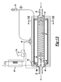
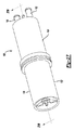
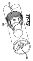
図27〜30を参照すると、洗浄流体加熱装置100が示される。加熱装置100は、細長く、概して円筒形のハウジングチャンバー104を形成するハウジング102を含む。
With reference to FIGS. 27-30, a cleaning
好ましくは、ハウジング102は2つのハウジング外殻106および108から形成され、これらはそれぞれ実質的に円筒形で、それぞれ開口端部110および112を有している。ハウジング外殻106および108のそれぞれの開口端部110および112は、例えばスピン溶接のような従来のあらゆる方法によって互いに固定されている。
Preferably, the
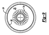
概して管状かつ円筒形のサブハウジング114はハウジングチャンバー104内に配置され、ハウジングチャンバー104を、サブハウジング114とハウジング102の間に形成された環状外部ハウジングチャンバー116と、サブハウジング114内に形成された内部ハウジングチャンバー118とに分割している。サブハウジング114はさらに、好適にはアルミニウムのような金属である熱伝導性材料で構成され、円周上で離間した複数のフィン120を有しており(図28)、このフィンは外部ハウジングチャンバー116のほぼ全体にわたって半径方向に延びている。サブハウジング114は金属突出部分を備えていることが好適である。
A generally tubular and
次に図28〜30を参照すると、円筒形コア122は内部ハウジングチャンバー118内に配置されている。このコア122は、その周囲で円周にかけて離間した複数のスタンドオフ124を含む。スタンドオフ124はコア122の全長に沿って延びていることが好適である。コア122とサブハウジング114の間に薄型で好適には均等な環状チャンバー126を形成するように、スタンドオフ124は内部ハウジングチャンバー118内のコア122の中心に設けられている。
Referring now to FIGS. 28-30, the
図28〜30に示す環状チャンバー126は管状および円筒形である。しかしながら、代替的には、環状チャンバー126は図10〜12に示すような組み合わせ式のフィンを含んでもよい。
The
コア122は、アルミニウムのような熱伝導性材料から成る。そのため、コア122は急速に温度上昇するだけでなく、熱エネルギーを蓄積する。
The
スタンドオフ124の高さは、環状チャンバー126の半径方向の厚さを画定している。図29に最良に示すように、環状チャンバー126の半径方向の厚さは、サブハウジング114の内部寸法と比較して非常に薄い。コア122は、環状チャンバー126の容量に対する環状チャンバー126の湿潤した壁面の面積に対する比率が少なくとも700m2/m3と等しくなる、好適には2000m2/m3を超えるように寸法される。
The height of the
図29に最良に示すように、フロントガラス洗浄流体インレット130はハウジング102の一端133に取り付けられるが、これと同様に、フロントガラス洗浄流体アウトレット134はハウジング102の他端132に取り付けられている。フロントガラス洗浄流体インレット130とアウトレット134の両方は、環状チャンバー126の対向する端部に流体的に開口している。流体インレット130と流体アウトレット134の両方はさらに、サブハウジング114の開口端部にかけて密封的に延びたキャップ138および140をそれぞれ含んでいる。この密封は、インレット130とアウトレット134とハウジング102の間の流体密封部136と組み合わせることで、インレット130とアウトレット134をハウジング102に対して流体的に密封し、環状チャンバー126を外部ハウジングチャンバー104から流体的に隔離する。しかしながら、端部キャップ138および140のへこみ125が、端部キャップ138および140をコア122から離間し、インレット130、アウトレット134および環状チャンバー126の間に流体連通を確立し、インレット130から環状チャンバー126を通りアウトレット134までの流体フローが確立する。
As best shown in FIG. 29, the windshield cleaning
次に図27および図29を参照すると、エンジン冷却剤インレット150はハウジング102の内部に形成され、外部ハウジングチャンバー104に開口している。同様に、冷却剤アウトレット152もハウジング102に取り付けられ、冷却剤インレット150から離間した位置に外部ハウジングチャンバー104に開口している。同図に示すように、冷却剤インレット150と冷却剤アウトレット152の両方は、ハウジング102の同じ端部133に取り付けられている。しかしながら、本発明の趣旨または適応範囲内から逸脱しない限り、冷却剤インレット150と冷却剤アウトレット152は、ハウジング102の対向する端部に取り付けることができる。
Referring now to FIGS. 27 and 29, the
場合により、フィルタを洗浄流体インレット130と連携させて、デブリ(debris)をサブハウジング114の内部に侵入しないようにしてもよい。
In some cases, a filter may be associated with the cleaning
動作中、フロントガラスワイパ流体インレット130は、ほとんどの車両に見られるフロントガラス洗浄流体ポンプなどの加圧フロントガラス洗浄流体の流体源に接続している。次に、フロントガラス洗浄流体アウトレット134は、車両に取り付けられ、車両のフロントガラスに向けられた噴霧噴出口か、既に先述したタイプのようなフロントガラスワイパブレードのいずれかに接続している。これにより、フロントガラス洗浄流体ポンプを作動させると、フロントガラス洗浄流体がインレット130内に汲み上げられ、環状チャンバー126を通り、洗浄流体アウトレット134から排出される。
In operation, the windshield
同時に、加熱されたエンジン冷却剤流体が冷却剤インレット150内に流れ、外部ハウジングチャンバー104を通り、冷却剤アウトレット152から排出される。漏出したいくらかのエンジン冷却剤が、ハウジング102の全長にわたり縦方向に流れずに、インレット150からアウトレット152へ直接流れてしまうことがあるが、ハウジング102を通って流れる大部分の冷却剤は、サブハウジング114上のフィン116によって、矢印154で示すようにハウジング102の一端133から他端132へ流される。ハウジングの端部133にある流体ダム155(図31)が端部キャップ138と当接することで、流体フローがインレット150からアウトレット152へ直接流れることを防止している。
At the same time, heated engine coolant fluid flows into the
エンジン冷却剤全体を外部ハウジングチャンバー104を通って流すために、また、冷却剤インレット150から冷却剤アウトレット152への直接の漏出を最小限にするため、フィン120とハウジング102の間に干渉フィンを作成することが好適である。
Interference fins are provided between the
動作中、エンジン冷却剤からの熱がサブハウジング114より伝導され、環状チャンバー126内のフロントガラス洗浄流体が加熱される。環状チャンバー126の容量に対する環状チャンバー126の湿潤面積の比率が非常に高いため、環状チャンバー126内のフロントガラス洗浄流体は急速に加熱されるだけでなく、ほぼ完全に加熱される。当然ながら、流体アウトレット134から放出されるフロントガラス洗浄流体の温度はエンジン冷却剤の温度とほぼ同じである。
During operation, heat from the engine coolant is conducted from the sub-housing 114 and the windshield cleaning fluid in the
実際には、フロントガラス洗浄システムの使用後、環状チャンバー126内のフロントガラス洗浄流体は単純に容器へ除去される。
In practice, after use of the windscreen cleaning system, the windscreen cleaning fluid in the
本発明を説明したが、本発明は、自動車のフロントガラスおよびワイパを迅速かつ効率的に除氷および除霜する、単純でありながら非常に有効な加熱式フロントガラスウォッシュ流体システムを提供することを見出すことが出来る。しかしながら、本発明を説明したが、添付の請求の範囲で定義された本発明の趣旨から逸脱しない限り、多くの改良が可能であることは当業者には明らかになるだろう。 Having described the present invention, the present invention provides a simple but highly effective heated windshield wash fluid system that quickly and efficiently deicers and defrosts the windshield and wiper of an automobile. Can be found. However, although the invention has been described, it will become apparent to those skilled in the art that many modifications can be made without departing from the spirit of the invention as defined in the appended claims.
Claims (12)
ハウジングチャンバーを画定する2つの端部を有するハウジングを備え、
前記ハウジングチャンバー内に配置されたサブハウジングをさらに備え、前記サブハウジングは熱伝導性材料で構成され、
前記ハウジングチャンバーを、前記ハウジングと前記サブハウジングの間の外部ハウジングチャンバーと、前記サブハウジング内の内部ハウジングチャンバーとに分離しており、前記内部ハウジングチャンバーと前記外部ハウジングチャンバーは互いに流体的に隔離されており、
前記内部ハウジングチャンバー内に配置されたコアをさらに備え、前記コアは前記コアと前記サブハウジングの間に環状チャンバーを形成しており、
前記環状チャンバーの一端に開口している、前記ハウジング上の洗浄流体インレットと、前記環状チャンバーの他端に開口している、前記ハウジング上の洗浄流体アウトレットとをさらに備え、
前記外部ハウジングチャンバーに開口するエンジン冷却剤インレットと、前記エンジン冷却剤インレットから離間した位置において前記外部ハウジングチャンバーに開口するエンジン冷却剤アウトレットとをさらに備え、これにより、前記冷却剤インレットに入った冷却剤の流れが前記外部ハウジングチャンバーを通り前記冷却剤アウトレットから排出されるようになっており、
前記コアは、前記環状チャンバーの容量に対する前記環状チャンバーの湿潤した表面面積の比率が700m 2 /m 3 を超えるように寸法されている、加熱装置。 A windshield cleaning fluid heating device,
A housing having two ends defining a housing chamber;
Further comprising a sub-housing disposed within the housing chamber, the sub-housing being composed of a thermally conductive material;
The housing chamber is separated into an outer housing chamber between the housing and the sub-housing, and an inner housing chamber in the sub-housing, and the inner housing chamber and the outer housing chamber are fluidly isolated from each other. And
A core disposed within the inner housing chamber, the core forming an annular chamber between the core and the sub-housing;
A cleaning fluid inlet on the housing that opens to one end of the annular chamber; and a cleaning fluid outlet on the housing that opens to the other end of the annular chamber;
Further comprising an engine coolant inlet opening to the outer housing chamber, and an engine coolant outlet opening to the outer housing chamber at a position remote from the engine coolant inlet, thereby, cooled entering the coolant inlet the flow of material are adapted to be discharged from the outer housing chamber through the coolant outlet, and
The heating device, wherein the core is dimensioned such that the ratio of the wetted surface area of the annular chamber to the volume of the annular chamber exceeds 700 m 2 / m 3 .
Applications Claiming Priority (5)
| Application Number | Priority Date | Filing Date | Title |
|---|---|---|---|
| US8957708P | 2008-08-18 | 2008-08-18 | |
| US61/089,577 | 2008-08-18 | ||
| US12/541,207 US8550147B2 (en) | 2008-08-18 | 2009-08-14 | Windshield washer fluid heater and system |
| US12/541,207 | 2009-08-14 | ||
| PCT/US2009/054132 WO2010022032A2 (en) | 2008-08-18 | 2009-08-18 | Windshield washer fluid heater and system |
Publications (3)
| Publication Number | Publication Date |
|---|---|
| JP2012500159A JP2012500159A (en) | 2012-01-05 |
| JP2012500159A5 JP2012500159A5 (en) | 2012-09-27 |
| JP5553071B2 true JP5553071B2 (en) | 2014-07-16 |
Family
ID=41680251
Family Applications (1)
| Application Number | Title | Priority Date | Filing Date |
|---|---|---|---|
| JP2011523926A Expired - Fee Related JP5553071B2 (en) | 2008-08-18 | 2009-08-18 | Windscreen cleaning fluid heating apparatus and system |
Country Status (7)
| Country | Link |
|---|---|
| US (1) | US8550147B2 (en) |
| EP (1) | EP2313295A4 (en) |
| JP (1) | JP5553071B2 (en) |
| KR (1) | KR20110044303A (en) |
| CN (1) | CN102123893B (en) |
| CA (1) | CA2732455A1 (en) |
| WO (1) | WO2010022032A2 (en) |
Families Citing this family (42)
| Publication number | Priority date | Publication date | Assignee | Title |
|---|---|---|---|---|
| US8925620B2 (en) * | 2008-08-18 | 2015-01-06 | Tsm Corporation | Windshield washer fluid heater |
| JP5535740B2 (en) * | 2010-04-14 | 2014-07-02 | 三菱重工業株式会社 | Heat medium heating device and vehicle air conditioner using the same |
| ES2865026T3 (en) * | 2010-04-23 | 2021-10-14 | Steam Tech Llc | Surface wiper system |
| FR2961457B1 (en) * | 2010-06-21 | 2013-04-26 | Valeo Systemes Dessuyage | WIPER BLADE WITH INTEGRATED SPRINKLER DEVICE |
| EP2428746B8 (en) * | 2010-09-13 | 2021-12-29 | MAHLE Behr GmbH & Co. KG | Heat exchanger |
| JP5257713B2 (en) * | 2011-02-10 | 2013-08-07 | アイシン精機株式会社 | Vehicle cooling system |
| US8807093B2 (en) * | 2011-05-19 | 2014-08-19 | Bock Water Heaters, Inc. | Water heater with multiple heat exchanging stacks |
| KR101252216B1 (en) * | 2011-10-17 | 2013-04-05 | 기아자동차주식회사 | Washer liquid heating apparatus and method in vehicle |
| US9963121B2 (en) | 2011-12-02 | 2018-05-08 | Mitsuba Corporation | Wiper blade |
| US8794195B2 (en) | 2012-02-03 | 2014-08-05 | Ford Global Technologies, Llc | Heat storage system for an engine |
| DE102012214480A1 (en) * | 2012-06-13 | 2013-12-19 | Eberspächer Climate Control Systems GmbH & Co. KG | The heat exchanger assembly |
| BG111311A (en) * | 2012-09-20 | 2014-03-31 | Станю СТОЙКОВ | Cleaning system of transparent surface vehicles |
| FR3002493B1 (en) * | 2013-02-28 | 2015-03-13 | Valeo Systemes Thermiques | ELECTRIC HEATER FOR A VEHICLE HEATING CIRCUIT |
| US9664451B2 (en) * | 2013-03-04 | 2017-05-30 | Rocky Research | Co-fired absorption system generator |
| CA2848077C (en) * | 2013-04-03 | 2018-03-13 | Shayne Elliott | Windshield washer fluid heating apparatus, control system, and method of using same |
| US9587215B2 (en) | 2014-08-07 | 2017-03-07 | General Electric Company | Devices, systems and methods for automated transfer of a sample |
| US20160167624A1 (en) * | 2014-12-16 | 2016-06-16 | Jere Rask Lansinger | Electrically heating windshield washer fluid system |
| KR102409471B1 (en) * | 2014-12-22 | 2022-06-16 | 가부시키가이샤 호리바 에스텍 | Fluid heater |
| US9623846B2 (en) * | 2015-01-06 | 2017-04-18 | Toyota Motor Engineering & Manufacturing North America, Inc. | Vehicle surface wash apparatus with heated wash fluid |
| CN104960500B (en) * | 2015-07-14 | 2017-02-01 | 安徽江淮汽车股份有限公司 | Control method and system for controlling defrosting heating device, and defrosting heating device |
| US10995998B2 (en) * | 2015-07-30 | 2021-05-04 | Senior Uk Limited | Finned coaxial cooler |
| GB201513415D0 (en) * | 2015-07-30 | 2015-09-16 | Senior Uk Ltd | Finned coaxial cooler |
| US10587218B2 (en) | 2015-09-07 | 2020-03-10 | Steam Tech, Llc | Panel maintenance system |
| CN105650861B (en) * | 2016-03-15 | 2018-10-26 | 华能无锡电热器材有限公司 | Equal temperature fields electric heating tube |
| US20170356692A1 (en) * | 2016-06-08 | 2017-12-14 | Savannah River Nuclear Solutions, Llc | Finned Heat Exchanger |
| US10717415B2 (en) | 2016-12-09 | 2020-07-21 | Seeva Technologies, Inc. | Washer fluid heating system and apparatus |
| JP2018154265A (en) * | 2017-03-17 | 2018-10-04 | 本田技研工業株式会社 | Vehicle washer device |
| EP3388294B1 (en) | 2017-04-10 | 2019-11-27 | Ford Otomotiv Sanayi Anonim Sirketi | Windshield washer fluid supply system |
| KR102415658B1 (en) * | 2017-08-09 | 2022-07-05 | 현대자동차주식회사 | Cooling water heating apparatus for electric vehicle |
| DE102018200044B4 (en) | 2018-01-03 | 2021-01-07 | Ford Global Technologies, Llc | Windshield air deflection rail |
| CN108657132A (en) * | 2018-03-23 | 2018-10-16 | 芜湖捷欧汽车部件有限公司 | A kind of new automobile water sprager |
| DE102018205280A1 (en) * | 2018-04-09 | 2019-10-10 | Mahle International Gmbh | PTC module |
| US10793116B2 (en) | 2018-06-11 | 2020-10-06 | Adrienne Sonja Bonne | Windshield cleaning assembly |
| US20200001832A1 (en) | 2018-06-27 | 2020-01-02 | Seeva Technologies, Inc. | Systems and methods for perception surface cleaning, drying, and/or thermal management with manifolds |
| KR102474521B1 (en) * | 2018-06-27 | 2022-12-05 | 현대자동차주식회사 | Washer Liquid Heating apparatus |
| US11638939B2 (en) | 2018-11-27 | 2023-05-02 | Steam Tech, Llc | Mobile panel cleaner |
| US11142167B2 (en) | 2019-01-07 | 2021-10-12 | Steam Tech, Llc | Wiper blade with directionally differentiated motion |
| JP7219683B2 (en) * | 2019-08-30 | 2023-02-08 | 株式会社村上開明堂 | Heating device for washer fluid |
| US11548482B2 (en) * | 2019-09-16 | 2023-01-10 | Blades Galore, Llc. | Placement and heating enhancement of windshield wipers for vehicle protection, including rearview mirror wipers |
| US12049201B2 (en) * | 2022-03-09 | 2024-07-30 | Ford Global Technologies, Llc | Vehicle sensor cleaning system |
| US20230303035A1 (en) * | 2022-03-25 | 2023-09-28 | Kenneth LaBruyere | Windshield washer solvent heater |
| CN115123145A (en) * | 2022-06-28 | 2022-09-30 | 上海洛轲智能科技有限公司 | Defrosting control system and method for front windshield of automobile |
Family Cites Families (121)
| Publication number | Priority date | Publication date | Assignee | Title |
|---|---|---|---|---|
| US1733408A (en) | 1929-10-29 | Windshield attachment | ||
| DE197803C (en) | ||||
| FR1194037A (en) | 1959-11-06 | |||
| US1153095A (en) | 1914-10-16 | 1915-09-07 | Thompson Robert W | Car-window cleaner. |
| US1228482A (en) | 1917-03-07 | 1917-06-05 | Frank Schonger | Antifrosting device. |
| US1410487A (en) | 1920-04-05 | 1922-03-21 | Mccarty Elonzo Clarence | Window |
| US1465292A (en) | 1920-12-24 | 1923-08-21 | Wessig August | Window-clearing apparatus |
| US1490168A (en) | 1923-01-10 | 1924-04-15 | James H Ford | Windshield heater |
| US1650922A (en) | 1923-12-24 | 1927-11-29 | Edward H Worthington | Windshield |
| US1556030A (en) | 1924-10-01 | 1925-10-06 | Joseph G Redshaw | Windshield cleaner and heater |
| US1835833A (en) | 1930-03-14 | 1931-12-08 | John F Schellhaas | Device for preventing accumulation of frost on windshields |
| US1933220A (en) | 1931-03-27 | 1933-10-31 | Frank L Petree | Electrical windshield heater |
| US1917141A (en) | 1931-10-09 | 1933-07-04 | Schwarze Electric Company | Defroster |
| US2002426A (en) * | 1932-02-25 | 1935-05-21 | Edmund E Allyne | Refrigerating apparatus |
| US2056776A (en) | 1933-08-28 | 1936-10-06 | E S Evans And Sons | Windshield warmer |
| US2032998A (en) | 1935-06-20 | 1936-03-03 | Josephine L Mickadeit | Air heated vision structure |
| US2125154A (en) | 1936-11-11 | 1938-07-26 | Hannah Fuller | Windshield heater for vehicles |
| US2260904A (en) | 1938-07-30 | 1941-10-28 | Trico Products Corp | Windshield clearing system |
| US2258922A (en) | 1939-04-04 | 1941-10-14 | Ray L Albee | Motor vehicle accessory |
| US2367426A (en) * | 1941-08-29 | 1945-01-16 | Patterson Ind Inc | Windshield protector and cleaner for airplanes |
| US2357426A (en) | 1943-05-28 | 1944-09-05 | Fred A Richards | Hopple for cows |
| US2576198A (en) | 1949-02-10 | 1951-11-27 | Ohio Commw Eng Co | Windshield sprayer |
| US2662154A (en) | 1951-09-11 | 1953-12-08 | Cochran William Joseph | Windshield wiper deicer |
| US2947020A (en) | 1952-12-22 | 1960-08-02 | Daimler Benz Ag | Windshield wiper arrangement for motor vehicles |
| US2847193A (en) * | 1954-08-30 | 1958-08-12 | Richard H Carter | Heat exchanger |
| US2738408A (en) | 1955-02-28 | 1956-03-13 | Wayne F Cheviron | Electric defrosting unit for vehicles |
| US2900168A (en) | 1955-03-24 | 1959-08-18 | Meredith M Nyborg | Reaction motor with liquid cooling means |
| US2894730A (en) * | 1955-06-21 | 1959-07-14 | Machlett Lab Inc | Cooling devices for electron tubes |
| US2839773A (en) | 1955-08-31 | 1958-06-24 | Kearfott Company Inc | Heated window wiper |
| US2968071A (en) | 1958-09-10 | 1961-01-17 | Perna Mario S Di | Windshield cleaner |
| US3135004A (en) | 1962-09-13 | 1964-06-02 | Naigraw John | Wiping and cleaning mechanism for external rear vision mirrors |
| US3243119A (en) | 1964-04-06 | 1966-03-29 | Leonard S Merkle | Apparatus for warming the fluid of a vehicle window washer system |
| US3321792A (en) | 1965-01-18 | 1967-05-30 | James M Heilman | Windshield wiper with hot air |
| US3366336A (en) | 1965-03-23 | 1968-01-30 | Fay A. Neuschwanger | Combination windshield heaterdefroster and washing system |
| US3292866A (en) | 1965-04-05 | 1966-12-20 | Donald E Benner | Windshield cleaning system |
| US3371368A (en) | 1965-05-24 | 1968-03-05 | Walker Harold Lloyd | Windshield wiper |
| US3319891A (en) | 1965-07-06 | 1967-05-16 | Virginia K Campbell | Electrically heated windshield washing nozzle in time delay circuit |
| DE1660306C3 (en) * | 1966-06-15 | 1975-11-27 | Hoechst Ag, 6000 Frankfurt | Heated godets for drawing synthetic threads |
| US3408678A (en) | 1966-08-17 | 1968-11-05 | Roy E. Linker | Windshield wiper assembly |
| US3560706A (en) | 1966-12-05 | 1971-02-02 | Eduardo J A Fonseca | Electric fluid heater and flow responsive switch therefor |
| US3489884A (en) | 1966-12-28 | 1970-01-13 | Texas Instruments Inc | Heated windshield wiper and blade therefor |
| ES349259A1 (en) * | 1967-01-04 | 1969-04-01 | Hourwitz | Gas-liquid finned heat exchanger |
| US3473348A (en) * | 1967-03-31 | 1969-10-21 | Edward W Bottum | Heat exchanger |
| US3447186A (en) | 1967-05-10 | 1969-06-03 | Alexander M Senkewich | Windshield wiper,defroster and washer |
| US3427675A (en) | 1967-07-03 | 1969-02-18 | James W Tibbet | Windshield wiper and washer assembly |
| US3416428A (en) | 1967-07-10 | 1968-12-17 | Walter K. Heller | Defroster and windshield heater |
| US3591887A (en) | 1969-02-13 | 1971-07-13 | James Edward Keddie | Windscreen washer device |
| US3568766A (en) * | 1969-03-11 | 1971-03-09 | Atomic Energy Commission | Corrugated heat exchange member for evaporation and condensation |
| US3574881A (en) | 1969-06-16 | 1971-04-13 | Reinhold Temple | Heated windshield wiper-spray assembly |
| US3632042A (en) * | 1969-10-20 | 1972-01-04 | Gen Motors Corp | Heated windshield washer system |
| US3688081A (en) | 1969-11-12 | 1972-08-29 | Pier Gianni Speich | Clear viewing screens |
| DE2011695A1 (en) | 1970-03-12 | 1971-09-30 | Köper, Franz Josef, 4370 Mari | Windshield washer device for motor vehicles |
| DE2112473C3 (en) | 1971-03-16 | 1973-10-18 | Audi Nsu Auto Union Ag, 7107 Neckarsulm | Heatable washing device for windows on motor vehicles |
| US3738252A (en) | 1971-07-14 | 1973-06-12 | A Cardinale | Concealed windshield wiper well heater |
| US3757088A (en) | 1972-02-29 | 1973-09-04 | Hercules Inc | He same electrically conducting elastomers and electrical members embodying t |
| US3868492A (en) | 1972-05-18 | 1975-02-25 | Tarka Controls Ltd | Heated windows in road vehicles |
| US3887004A (en) * | 1972-06-19 | 1975-06-03 | Hayden Trans Cooler Inc | Heat exchange apparatus |
| US3835294A (en) | 1973-04-06 | 1974-09-10 | Binks Mfg Co | High pressure electric fluid heater |
| US3888412A (en) | 1973-04-17 | 1975-06-10 | Kenilworth Research & Dev Corp | Apparatus for heating the fluid in a windshield washer system |
| US3935425A (en) | 1973-11-07 | 1976-01-27 | David Weissberger | Mechanized electrically heated windshield cleaner |
| US4132881A (en) | 1973-12-12 | 1979-01-02 | Societa Italiana Vetro Siv S.P.A. | Electrically heated vehicle window having plural moisture sensing probes |
| DE2507037B1 (en) | 1975-02-19 | 1976-02-26 | Audi Nsu Auto Union Ag | ELECTRICALLY HEATED REAR WINDOW FOR VEHICLES |
| SE388571B (en) | 1975-02-24 | 1976-10-11 | Bergkvist Lars A | DEVICE FOR CLEANING THE VEHICLE WINDSCREEN, STRALKASTARGLASS, REAR MIRROR, REFLEXDON E D |
| US4127763A (en) | 1975-04-17 | 1978-11-28 | Saint-Gobain Industries | Heated window with a moisture sensor having a high impedance |
| US4088269A (en) | 1975-11-06 | 1978-05-09 | Vdo Adolf Schindling Ag | Electrically heated windshield washer spray nozzle assembly |
| US4037286A (en) | 1976-01-14 | 1977-07-26 | Medearis G P | Rearview mirror for vehicles |
| DE2615824B2 (en) | 1976-04-10 | 1978-04-27 | Wigo Gottlob Widmann & Soehne Gmbh Und Co Kg, 7220 Villingen-Schwenningen | Household coffee machine with calcification display |
| US4059882A (en) * | 1976-05-24 | 1977-11-29 | United Aircraft Products, Inc. | Method of making an annular tube-fin heat exchanger |
| US4096616A (en) * | 1976-10-28 | 1978-06-27 | General Electric Company | Method of manufacturing a concentric tube heat exchanger |
| US4096910A (en) | 1976-10-28 | 1978-06-27 | General Electric Company | Concentric-tube stacked plate heat exchanger |
| FR2371322A1 (en) | 1976-11-19 | 1978-06-16 | Renault | CLEANING AND DEFOGGING DEVICE, ESPECIALLY OF THE REAR WINDOW OF A MOTOR VEHICLE |
| US4085308A (en) | 1976-11-26 | 1978-04-18 | Rex Veech Youngquist | Electric water heater for showers |
| US4090668A (en) | 1976-12-06 | 1978-05-23 | Kochenour Paul R | Windshield washer and deicer |
| US4180723A (en) | 1977-03-28 | 1979-12-25 | Corning Glass Works | Electrical contacts for electrically conductive carbon glasses |
| SE423276B (en) * | 1977-12-01 | 1982-04-26 | Karl Ostbo | HEAT EXCHANGER INCLUDING A MULTIPLE INHIBITOR PARALLEL BROUGHT PLATES |
| US4212425A (en) | 1978-02-27 | 1980-07-15 | Vdo Adolf Schindling Ag. | Electrically heated windshield washer spray nozzle assembly |
| US4145788A (en) | 1978-03-30 | 1979-03-27 | John Ferrarelli | Ice shield |
| DE2962428D1 (en) * | 1978-04-24 | 1982-05-19 | Anderstorps Werkstads Ab | A device for heating liquid for one or several washer systems |
| JPS5532224U (en) | 1978-08-24 | 1980-03-01 | ||
| US4236548A (en) | 1979-06-01 | 1980-12-02 | Howard E W | Apparatus for providing instant hot water |
| JPS5683555U (en) | 1979-12-03 | 1981-07-06 | ||
| EP0104673B1 (en) | 1982-09-24 | 1987-11-19 | Onofrio Rocchitelli | Heating device for the glass washing fluid of motor vehicles and the like |
| JPS5969048U (en) * | 1982-10-30 | 1984-05-10 | カルソニックカンセイ株式会社 | window washer device |
| US4575003A (en) * | 1984-05-10 | 1986-03-11 | Hotshot Auto Products Inc. | Fluid heating attachment for automobile engine cooling systems |
| CA1291113C (en) * | 1985-03-22 | 1991-10-22 | Keith Stuart Mclaren | Heat exchanger |
| DE3512108C1 (en) | 1985-04-03 | 1986-05-22 | Bayerische Motoren Werke AG, 8000 München | Windscreen washer device for motor vehicles |
| BR8604382A (en) * | 1985-09-14 | 1987-05-12 | Norsk Hydro As | FLUID COOLER |
| US4665351A (en) | 1986-02-05 | 1987-05-12 | General Motors Corporation | Windshield wiper control system and a precipitation sensor therefor |
| GB8606905D0 (en) | 1986-03-20 | 1986-04-23 | Trico Folberth Ltd | Blade rubber |
| US4763381A (en) | 1986-05-28 | 1988-08-16 | Williams George A | Accessory used to keep outside rear view mirrors of vehicles clear of water, snow, ice and dirt |
| FR2604405B1 (en) | 1986-09-29 | 1990-05-11 | Delluc Rene | DEVICE FOR AUTOMATIC WASHING AND DEFROSTING OF WINDSCREENS OF MOTOR VEHICLES |
| US4832262A (en) | 1986-12-12 | 1989-05-23 | Robertson Harry J | Automobile window washing apparatus and heat exchanger therefor |
| DE3737241A1 (en) | 1986-12-18 | 1988-07-28 | Anton Lohrum | DEVICE FOR MOTOR VEHICLES WITH LIQUID-COOLED ENGINE FOR HEATING WINDOW WASHING LIQUID OR THE LIKE |
| JPS63134274U (en) * | 1987-02-20 | 1988-09-02 | ||
| DE3714224A1 (en) | 1987-04-29 | 1988-11-17 | Swf Auto Electric Gmbh | WINDOW WIPER |
| US4910380A (en) | 1987-07-21 | 1990-03-20 | Flachglass Aktiengesellschaft | Vehicle window with black obscuration band incorporating a black electrically conductive coating-deposited heating element |
| US4834172A (en) * | 1988-01-12 | 1989-05-30 | W. Schmidt Gmbh & Co. Kg | Heat exchanger |
| US4967437A (en) | 1988-05-27 | 1990-11-06 | Engineering Plastics, Inc. | Heated wiper blade assembly |
| JPH02216347A (en) | 1989-02-15 | 1990-08-29 | Fuji Heavy Ind Ltd | Antifrost device for vehicle |
| DE3907968A1 (en) | 1989-03-11 | 1990-09-13 | Swf Auto Electric Gmbh | WINDOW CLEANING SYSTEM |
| US5325561A (en) | 1989-07-05 | 1994-07-05 | Kotlar Edward A | Heated flexible windshield wiper |
| JPH0411175U (en) | 1990-05-17 | 1992-01-30 | ||
| CA2049452A1 (en) | 1990-08-21 | 1992-02-22 | Sheng-Hann Lee | Window cleaning fluid heating system |
| US5065471A (en) | 1990-11-09 | 1991-11-19 | Sylvain Laplante | Antifreeze self-spraying and -warming windshield wiper |
| US5107922A (en) * | 1991-03-01 | 1992-04-28 | Long Manufacturing Ltd. | Optimized offset strip fin for use in contact heat exchangers |
| DE4111937A1 (en) | 1991-04-12 | 1992-10-15 | Citadel Investments | CLEANING SYSTEM FOR WINDSHIELDS ON MOTOR VEHICLES, AIRPLANES, LOCOMOTIVES OR THE LIKE |
| US5099909A (en) | 1991-05-31 | 1992-03-31 | Giuseppe Barigelli | Surface type heat exchanger for heating the water feeding the windshield washer of automobiles and for heating the diesel oil |
| US5264962A (en) | 1991-08-22 | 1993-11-23 | Kho Myung D | Sideview mirror for vehicles |
| US5221828A (en) | 1992-07-16 | 1993-06-22 | General Motors Corporation | Heated wiper blade using conductive elastomer |
| US5509606A (en) | 1993-10-04 | 1996-04-23 | Koltech, Inc. | Instant hot wash device |
| US5426814A (en) | 1994-01-31 | 1995-06-27 | Minnick; Leonard J. | Heated windshield wiper with fluid dispensing means |
| US5522453A (en) * | 1995-03-22 | 1996-06-04 | Green; Kenneth E. | Washer fluid heater |
| KR970040211A (en) * | 1995-12-28 | 1997-07-24 | 김태구 | Heated Washer Hose |
| US5881428A (en) | 1996-02-22 | 1999-03-16 | Simmons; David L. | Windshield and windshield wiper heating apparatus assembly |
| JPH10309451A (en) * | 1997-05-08 | 1998-11-24 | Noritake Co Ltd | Static mixer for heat exchanger |
| US5957384A (en) | 1997-08-26 | 1999-09-28 | Lansinger; Jere Rask | Windshield heated wiping system |
| JP2001171487A (en) | 1999-12-20 | 2001-06-26 | Omata Haikan Yosetsu:Kk | Washer liquid heating device for vehicle |
| US6789744B2 (en) * | 2002-01-29 | 2004-09-14 | Valeo Electrical Systems, Inc. | Fluid heater with a variable mass flow path |
| US6902118B2 (en) | 2002-10-02 | 2005-06-07 | Sbr Investments Company Llc | Vehicle windshield cleaning system |
| JP2005083741A (en) * | 2003-09-05 | 2005-03-31 | Lg Electronics Inc | Air conditioner having heat exchanger and refrigerant switching means |
| WO2005104690A2 (en) * | 2004-04-16 | 2005-11-10 | Patrick James Mcnaughton | Windshield heat and clean |
-
2009
- 2009-08-14 US US12/541,207 patent/US8550147B2/en not_active Expired - Fee Related
- 2009-08-18 JP JP2011523926A patent/JP5553071B2/en not_active Expired - Fee Related
- 2009-08-18 WO PCT/US2009/054132 patent/WO2010022032A2/en active Application Filing
- 2009-08-18 KR KR1020117006148A patent/KR20110044303A/en not_active Application Discontinuation
- 2009-08-18 CA CA2732455A patent/CA2732455A1/en not_active Abandoned
- 2009-08-18 CN CN200980132282.8A patent/CN102123893B/en not_active Expired - Fee Related
- 2009-08-18 EP EP09808698.6A patent/EP2313295A4/en not_active Withdrawn
Also Published As
| Publication number | Publication date |
|---|---|
| EP2313295A2 (en) | 2011-04-27 |
| WO2010022032A3 (en) | 2010-07-29 |
| WO2010022032A2 (en) | 2010-02-25 |
| US20100037415A1 (en) | 2010-02-18 |
| CN102123893A (en) | 2011-07-13 |
| CN102123893B (en) | 2014-03-19 |
| CA2732455A1 (en) | 2010-02-25 |
| EP2313295A4 (en) | 2014-04-23 |
| JP2012500159A (en) | 2012-01-05 |
| KR20110044303A (en) | 2011-04-28 |
| US8550147B2 (en) | 2013-10-08 |
Similar Documents
| Publication | Publication Date | Title |
|---|---|---|
| JP5553071B2 (en) | Windscreen cleaning fluid heating apparatus and system | |
| US20160167624A1 (en) | Electrically heating windshield washer fluid system | |
| CA2657976C (en) | Vehicle surfaces cleaning and de-icing system and method | |
| US7657961B2 (en) | Vehicle windshield cleaning system | |
| KR101320762B1 (en) | Frameless, heated wiper assembly and system utilizing same | |
| US7959090B2 (en) | Vehicle windshield cleaning system | |
| EP1667800B1 (en) | Vehicle windshield cleaning system | |
| EP0944508B1 (en) | Method and means of heating a washer nozzle in a windscreen wiper system | |
| US10717415B2 (en) | Washer fluid heating system and apparatus | |
| US20120174333A1 (en) | Wiper fluid heater | |
| US20120125563A1 (en) | Windsheild washer fluid heater | |
| US8820334B2 (en) | Apparatus for heating washer liquid | |
| JP4960650B2 (en) | Automotive wind glass cleaning equipment | |
| CA2625146A1 (en) | Vehicle surface cleaning and de-icing | |
| CN208149266U (en) | A kind of hot type device for cleaning windshield glass | |
| KR20160065470A (en) | washer liquid heating apparatus for automobile | |
| LT4741B (en) | Windshield de-icing | |
| EP0261005B1 (en) | Apparatus for warming a window washer liquid for a motor vehicle | |
| US20060243821A1 (en) | Heated windshield washer fluid system | |
| RU2547038C1 (en) | Vehicle windscreen washing system | |
| KR101180088B1 (en) | The window washer liquid tank and that manufacturring structure for an automobil | |
| WO2006081469A2 (en) | Vehicle windshield cleaning system | |
| CN110654348A (en) | Detachable snow and ice removing device for front windshield of automobile and windscreen wiper | |
| JP2003170815A (en) | Wiper |
Legal Events
| Date | Code | Title | Description |
|---|---|---|---|
| A521 | Request for written amendment filed |
Free format text: JAPANESE INTERMEDIATE CODE: A523 Effective date: 20120813 |
|
| A621 | Written request for application examination |
Free format text: JAPANESE INTERMEDIATE CODE: A621 Effective date: 20120813 |
|
| A977 | Report on retrieval |
Free format text: JAPANESE INTERMEDIATE CODE: A971007 Effective date: 20131126 |
|
| A131 | Notification of reasons for refusal |
Free format text: JAPANESE INTERMEDIATE CODE: A131 Effective date: 20131219 |
|
| A521 | Request for written amendment filed |
Free format text: JAPANESE INTERMEDIATE CODE: A523 Effective date: 20140319 |
|
| TRDD | Decision of grant or rejection written | ||
| A01 | Written decision to grant a patent or to grant a registration (utility model) |
Free format text: JAPANESE INTERMEDIATE CODE: A01 Effective date: 20140501 |
|
| A61 | First payment of annual fees (during grant procedure) |
Free format text: JAPANESE INTERMEDIATE CODE: A61 Effective date: 20140513 |
|
| R150 | Certificate of patent or registration of utility model |
Ref document number: 5553071 Country of ref document: JP Free format text: JAPANESE INTERMEDIATE CODE: R150 |
|
| R250 | Receipt of annual fees |
Free format text: JAPANESE INTERMEDIATE CODE: R250 |
|
| R250 | Receipt of annual fees |
Free format text: JAPANESE INTERMEDIATE CODE: R250 |
|
| R250 | Receipt of annual fees |
Free format text: JAPANESE INTERMEDIATE CODE: R250 |
|
| R250 | Receipt of annual fees |
Free format text: JAPANESE INTERMEDIATE CODE: R250 |
|
| LAPS | Cancellation because of no payment of annual fees |