KR20110044303A - Windshield washer fluid heater and system - Google Patents
Windshield washer fluid heater and system Download PDFInfo
- Publication number
- KR20110044303A KR20110044303A KR1020117006148A KR20117006148A KR20110044303A KR 20110044303 A KR20110044303 A KR 20110044303A KR 1020117006148 A KR1020117006148 A KR 1020117006148A KR 20117006148 A KR20117006148 A KR 20117006148A KR 20110044303 A KR20110044303 A KR 20110044303A
- Authority
- KR
- South Korea
- Prior art keywords
- housing
- chamber
- washer fluid
- annular chamber
- windshield
- Prior art date
Links
Images


Classifications
-
- B—PERFORMING OPERATIONS; TRANSPORTING
- B60—VEHICLES IN GENERAL
- B60S—SERVICING, CLEANING, REPAIRING, SUPPORTING, LIFTING, OR MANOEUVRING OF VEHICLES, NOT OTHERWISE PROVIDED FOR
- B60S1/00—Cleaning of vehicles
- B60S1/02—Cleaning windscreens, windows or optical devices
- B60S1/46—Cleaning windscreens, windows or optical devices using liquid; Windscreen washers
- B60S1/48—Liquid supply therefor
- B60S1/487—Liquid supply therefor the liquid being heated
-
- B—PERFORMING OPERATIONS; TRANSPORTING
- B60—VEHICLES IN GENERAL
- B60H—ARRANGEMENTS OF HEATING, COOLING, VENTILATING OR OTHER AIR-TREATING DEVICES SPECIALLY ADAPTED FOR PASSENGER OR GOODS SPACES OF VEHICLES
- B60H1/00—Heating, cooling or ventilating [HVAC] devices
- B60H1/00271—HVAC devices specially adapted for particular vehicle parts or components and being connected to the vehicle HVAC unit
-
- B—PERFORMING OPERATIONS; TRANSPORTING
- B60—VEHICLES IN GENERAL
- B60H—ARRANGEMENTS OF HEATING, COOLING, VENTILATING OR OTHER AIR-TREATING DEVICES SPECIALLY ADAPTED FOR PASSENGER OR GOODS SPACES OF VEHICLES
- B60H1/00—Heating, cooling or ventilating [HVAC] devices
- B60H1/24—Devices purely for ventilating or where the heating or cooling is irrelevant
- B60H1/241—Devices purely for ventilating or where the heating or cooling is irrelevant characterised by the location of ventilation devices in the vehicle
- B60H1/242—Devices purely for ventilating or where the heating or cooling is irrelevant characterised by the location of ventilation devices in the vehicle located in the front area
-
- B—PERFORMING OPERATIONS; TRANSPORTING
- B60—VEHICLES IN GENERAL
- B60S—SERVICING, CLEANING, REPAIRING, SUPPORTING, LIFTING, OR MANOEUVRING OF VEHICLES, NOT OTHERWISE PROVIDED FOR
- B60S1/00—Cleaning of vehicles
- B60S1/02—Cleaning windscreens, windows or optical devices
- B60S1/023—Cleaning windscreens, windows or optical devices including defroster or demisting means
-
- B—PERFORMING OPERATIONS; TRANSPORTING
- B60—VEHICLES IN GENERAL
- B60S—SERVICING, CLEANING, REPAIRING, SUPPORTING, LIFTING, OR MANOEUVRING OF VEHICLES, NOT OTHERWISE PROVIDED FOR
- B60S1/00—Cleaning of vehicles
- B60S1/02—Cleaning windscreens, windows or optical devices
- B60S1/46—Cleaning windscreens, windows or optical devices using liquid; Windscreen washers
- B60S1/48—Liquid supply therefor
- B60S1/52—Arrangement of nozzles; Liquid spreading means
- B60S1/522—Arrangement of nozzles; Liquid spreading means moving liquid spreading means, e.g. arranged in wiper arms
- B60S1/524—Arrangement of nozzles; Liquid spreading means moving liquid spreading means, e.g. arranged in wiper arms arranged in wiper blades
-
- B—PERFORMING OPERATIONS; TRANSPORTING
- B60—VEHICLES IN GENERAL
- B60S—SERVICING, CLEANING, REPAIRING, SUPPORTING, LIFTING, OR MANOEUVRING OF VEHICLES, NOT OTHERWISE PROVIDED FOR
- B60S1/00—Cleaning of vehicles
- B60S1/02—Cleaning windscreens, windows or optical devices
- B60S1/54—Cleaning windscreens, windows or optical devices using gas, e.g. hot air
-
- F—MECHANICAL ENGINEERING; LIGHTING; HEATING; WEAPONS; BLASTING
- F01—MACHINES OR ENGINES IN GENERAL; ENGINE PLANTS IN GENERAL; STEAM ENGINES
- F01P—COOLING OF MACHINES OR ENGINES IN GENERAL; COOLING OF INTERNAL-COMBUSTION ENGINES
- F01P3/00—Liquid cooling
- F01P3/12—Arrangements for cooling other engine or machine parts
-
- B—PERFORMING OPERATIONS; TRANSPORTING
- B60—VEHICLES IN GENERAL
- B60S—SERVICING, CLEANING, REPAIRING, SUPPORTING, LIFTING, OR MANOEUVRING OF VEHICLES, NOT OTHERWISE PROVIDED FOR
- B60S1/00—Cleaning of vehicles
- B60S1/02—Cleaning windscreens, windows or optical devices
- B60S1/04—Wipers or the like, e.g. scrapers
- B60S1/32—Wipers or the like, e.g. scrapers characterised by constructional features of wiper blade arms or blades
- B60S1/38—Wiper blades
- B60S2001/3898—Wiper blades method for manufacturing wiper blades
Landscapes
- Engineering & Computer Science (AREA)
- Mechanical Engineering (AREA)
- Water Supply & Treatment (AREA)
- Physics & Mathematics (AREA)
- Thermal Sciences (AREA)
- Chemical & Material Sciences (AREA)
- Combustion & Propulsion (AREA)
- General Engineering & Computer Science (AREA)
- Air-Conditioning For Vehicles (AREA)
- Cleaning By Liquid Or Steam (AREA)
Abstract
윈드실드 워셔액 히터는 하우징 챔버를 형성하는 하우징을 포함한다. 서브하우징은 하우징 챔버 내부에 위치한다. 서브하우징은 열 전도성 재료로 이루어지며 하우징 챔버를 하우징과 서브하우징 사이의 외측 하우징 챔버와 서브하우징 내부의 내측 하우징 챔버로 나눈다. 외측 하우징 챔버와 내측 하우징 챔버는 서로 유체적으로 분리되어 있다. 코어는 내측 하우징 챔버 내에 위치하며 서브하우징과의 사이에 환형 챔버를 형성한다. 워셔액 입구는 하우징 상에 위치하여 환형 챔버의 일단부에 대해 개방되어 있으며, 워셔액 출구는 하우징 상에 위치하여 환형 챔버의 타단부에 대해 개방되어 있다. 엔진 냉각수 입구는 외측 하우징 챔버에 대해 개방되어 있으며, 엔진 냉각수 출구는 냉각수 입구로부터 이격된 위치에서 외측 하우징 챔버에 대해 개방되어 있다. 이에 의하면, 워셔액이 엔진 냉각수 입구로 들어가서 외측 하우징 챔버를 거쳐 엔진 냉각수 출구로 흐른다. 환형 유체 챔버를 포함하는 하우징 챔버를 가열하기 위해 전기 히터를 포함할 수 있다. The windshield washer fluid heater includes a housing forming a housing chamber. The subhousing is located inside the housing chamber. The sub-housing is made of a thermally conductive material and divides the housing chamber into an outer housing chamber between the housing and the sub-housing and an inner housing chamber inside the sub-housing. The outer housing chamber and the inner housing chamber are fluidly separated from each other. The core is located in the inner housing chamber and forms an annular chamber with the subhousing. The washer fluid inlet is located on the housing and open to one end of the annular chamber, and the washer fluid inlet is located on the housing and open to the other end of the annular chamber. The engine coolant inlet is open to the outer housing chamber, and the engine coolant outlet is open to the outer housing chamber at a position away from the coolant inlet. According to this, the washer liquid enters the engine coolant inlet and flows through the outer housing chamber to the engine coolant outlet. An electrical heater may be included to heat the housing chamber including the annular fluid chamber.
Description
본 발명은 가열한 워셔액을 사용하는 차량용 윈드실드 디프로스터(vehicle windshield defroster) 및 와이퍼(wiper)에 관한 것이다. BACKGROUND OF THE
관련 출원의 상호참조Cross reference of related application
본 출원은 2008년 8월 18일에 출원된 미국 가출원 제61/089,577호 및 2009년 8월 14일에 출원된 미국출원 제12/541,207호의 우선권을 주장하며, 상기 문헌들의 내용을 본 명세서에 참조에 의해 포함한다. This application claims the priority of US Provisional Application No. 61 / 089,577, filed August 18, 2008 and US Application No. 12 / 541,207, filed August 14, 2009, the contents of which are incorporated herein by reference. Included by.
자동차 윈드실드(windshield) 및 와이퍼(wiper)의 제상(defrost) 및 제빙(deice)을 위해, 종래에는 온풍 디프로스터(warm air defroster)를 사용해 왔다. 신속하고 안전한 운전 시야를 확보하고자 하는 운전자는 이러한 디프로스터의 성능이 느리고 불량한 것에 대해 불만이 많아지고 있다. 정부 주도의 차량 안전 표준(예를 들어, 1960년대 자동차 온풍 디프로스터 미니멀 기술에 기초한 FMVSS103)에서는 최소의 제상 성능 요건을 설정하고 있지만, 0℉(화씨)에서 미리 정한 표준량의 성에(frost)를 제거하기 위해서는 엔진의 냉간 시동(cold start)부터 30분을 기다려야 한다. 기존의 차량[CAFE(Corporate Average Fuel Economy: 미국 기업 평균연비) 기준으로 갤런당 27.5 마일]의 경우에도 이러한 시험에서 윈드실드의 성에를 제거하기 위해 통상 15분 내지 25분이 걸린다. For the defrost and deice of automotive windshields and wipers, conventionally warm air defrosters have been used. Drivers who want fast and safe driving vision are increasingly dissatisfied with the slow and poor performance of these defrosters. Government-led vehicle safety standards (e.g. FMVSS103 based on 1960's automotive warm air defroster minimalist technology) set minimum defrost performance requirements, but eliminated pre-determined standard amounts of frost at 0 ° F. To do this, wait 30 minutes from the cold start of the engine. Even existing vehicles (27.5 miles per gallon based on Corporate Average Fuel Economy (CAFE)) typically take 15-25 minutes to defrost the windshield in these tests.
따라서, 일반적인 경우, 운전자가 윈드실드에서 성에를 긁어내고 와이퍼 블레이드에서 얼음을 떼어내어야 하거나, 디프로스터가 제대로 작동하도록 엔진을 예열함으로써 연료가 낭비되고 많은 시간이 걸린다. 윈도실드는 아이스 스크레이퍼(ice scraper)를 효과적으로 사용하는 것이 특히 어려우며, 이러한 상황은 윈드실드에서 성에를 신속하면서 민첩하게 긁어내기 힘든 노년의 7천8백만 베이비붐 세대로 가고 있는 미국에서 문제가 심각해지고 있다. 또한, 지구 온난화에 의해 겨울 시즌을 포함해서 더 혹한의 폭풍우가 만들어지고 있다. Thus, in the general case, the driver has to scrape the frost from the windshield and remove the ice from the wiper blades, or preheat the engine for the defroster to work properly, which wastes fuel and takes a lot of time. Windows shields are especially difficult to use ice scrapers effectively, and this situation is becoming more serious in the United States, where the windshield is going to the older age of 78 million baby boomers who are unable to scrape frost quickly and quickly. have. In addition, global warming is creating more severe storms, including the winter season.
특히 전기 가열식 윈드실드 및 최신의 보다 효과적인 가열식 워셔 시스템과 같은 양호한 가용 기술의 관점에서, 혹한기(winter weather) 운전자는 더 양호한 성능의 디프로스터를 필요로 할 것이다. 양호한 제상(defrosting) 시스템에 대한 필요성을 더 높이는 것은, 2015년까지 한층 강화된 수준의 새롭게 법제화한 35.5 mpg(갤런당 35.5 마일의 주행) CAFE 요건, 석유에 덜 의존하는 국가 경제(연료 가격의 급등), 및 환경 친화적인 차량을 달성하기 위해, 높은 연료 효율을 가진 내연기관 차량, 하이브리드 차량, 플러그인 하이브리드(plug-in hybrid) 전기 차량, 풀 배터리(full battery) 전기 차량 및 연료 전지(fuel cell) 전기 차량이 급격히 증가하고 있다는 것이다. In particular in terms of good available technology, such as electrically heated windshields and state-of-the-art, more efficient heated washer systems, winter weather drivers will need better performance defrosters. Further increasing the need for a good defrosting system is the newly enacted 35.5 mpg (35.5 mile per gallon) CAFE requirement, which is further enhanced by 2015, the national economy less dependent on oil (surge in fuel prices). And high fuel efficiency internal combustion engine vehicles, hybrid vehicles, plug-in hybrid electric vehicles, full battery electric vehicles and fuel cells to achieve environmentally friendly vehicles. Electric vehicles are increasing rapidly.
이처럼 새롭게 생기고 있는 차량의 높은 연비 때문에, 통상적인 엔진 냉각수 가열에 기반을 둔 온풍 디프로스터 및 히터가 제대로 수행될 수 있도록 하기 위해서는, "낭비되는 열" 에너지를 실질적으로 줄여야 한다. 자동차 제조업자와 공급업자는, 높은 연비를 갖는 차량의 새로운 요구에 부합하도록, 축열(heat storage), 히트 펌프(heat pump), 전기 가열(electric heating), 점성 마찰 히터(viscous friction heater), 냉각수 난류 히터(coolant turbulence heater), 및 연료 연소식 히터(fuel fired heater)와 같은 새로운 디프로스터 및 히터 기술을 활발하게 연구 및 개발하고 있다. 오늘날 통상적인 연비가 낮은 차량과 "낭비되는 열"이 많은 차량은 더 이상 쓸모 없어지게 될 것이다. 운전하기 전에 윈드실드의 성에를 제거하기 위해 장시간 동안 엔진을 예열(warm up)하는 통상적인 방식은 환경 오염 및 수입 기름에 대한 에너지 의존성을 감소시킨다고 하는 오늘날의 공통된 목표에 반하는 것이다. Due to the high fuel economy of this emerging vehicle, it is necessary to substantially reduce the "wasted heat" energy to ensure that hot air defrosters and heaters based on conventional engine coolant heating are properly performed. Automotive manufacturers and suppliers are looking for heat storage, heat pumps, electric heating, viscous friction heaters and cooling water turbulence to meet the new demands of high fuel economy vehicles. New defroster and heater technologies such as coolant turbulence heaters and fuel fired heaters are being actively researched and developed. Today's conventional low fuel economy vehicles and vehicles with a high amount of "wasted heat" will no longer be useful. The usual way of warming up the engine for a long time to defrost the windshield before driving is against today's common goal of reducing environmental pollution and energy dependence on imported oil.
원격 시동 기술이 몇 년에 걸쳐 부품 시장에서 사용되고 있으며 최근에는 제상, 가열 및 공기조화 성능을 향상시키기 위한 기본적인 장비 요소로서 대중화되고 있다. 그러나, 미국의 많은 주와 많은 나라의 공회전 방지법(anti-idling laws)은, 공기 오염을 줄이고 연비를 향상시키기 위해, 허용가능한 공회전 시간을 크게 제한(현재는 일반적으로 5분 이하로)하고 있으며, 원격 시동 기술은 그에 상응하는 공회전 시간 규제를 받게 될 것이다. Remote start technology has been used in the aftermarket for several years and has recently become popular as a basic equipment element for improving defrosting, heating and air conditioning performance. However, anti-idling laws in many US and many countries in the United States greatly limit the allowable idle time (currently generally below 5 minutes) to reduce air pollution and improve fuel economy, Remote start technology will be subject to corresponding idle time regulation.
전기 가열식 윈드실드(electrically heated windshield)는 제상 시간(defrost time)을 크게 줄이지만 비용이 많이 들고 복잡하며 신뢰성이 떨어지기 때문에 제한적으로만 사용되고 있으며, 전자 통신 장치와의 간섭(interference)과 같은 기술적인 문제도 있다. 전기 가열식 윈드실드의 교체 비용은 통상적인 윈드실드의 교체 비용보다 몇 배(예를 들어, 5배 많은 경우도 있음) 많이 들고, 평균 차량이 그 수명 동안 대략 1과 1/2개의 윈드실드 교체 주기를 갖는다. 눈에 보이는 열선(heating wire) 및 열처리 필름(heating film)은 시야를 산만하게 하고 윈드실드의 선명도와 투명도를 떨어뜨릴 수 있다. Electrically heated windshields greatly reduce defrost time, but are only limitedly used due to their high cost, complexity and reliability, and are often used in technical applications such as interference with electronic communication devices. There is a problem. The replacement cost of an electrically heated windshield is several times higher (for example, sometimes five times more) than that of a conventional windshield, and the average vehicle has approximately one and a half windshield replacement cycles over its lifetime. Has Visible heating wires and heating films can distract the field of view and reduce the clarity and transparency of the windshield.
통상적인 노즐(nozzle)을 통해 분사되는 전기 가열식 워셔액 시스템은 부품 시장에서는 제한적으로 성공했지만, 최근에는 온풍 디프로스터 시스템의 윈드실드 및 와이퍼의 제빙 성능을 향상시키기 위해 장비 시장에서 다시 부각되고 있다. 전기 과열 고장(electrical overheating failure)은 적어도 하나의 대규모 제품 리콜의 원인이 되고 있다. 세계에서 가장 큰 자동차 회사 중의 하나는 최근에 많은 모델에 대해 가열식 워셔 시스템(heated washer system) 기술을 제공하고 있으며, 다른 자동차 회사들도 이러한 기술을 출시할 계획을 가지고 있다. 하지만, 이러한 시스템에서도, 많은 사용자는 성능, 기능성 및 신뢰성이 부족하다는 의견을 내놓고 있다. 이러한 가열식 워셔 시스템이 FMVSS103 제상 시간을 통상 15~25분에서 5~10분으로 감소시킬 수 있지만, 운전자는 여전히 성에 제거가 더 빨리 되기를 원하고 있다. 또한, 겨울철의 결빙이 생기고 눈보라가 치는 조건에서 운전을 할 때에, 와이퍼와 윈드실드에 결빙이 생겨서 시야가 불량하게 되기 때문에, 온풍 프로스터를 최대 출력으로 사용해도, 시판되고 있는 가열식 워셔 시스템으로는 결빙을 신속하고 효과적으로 제거하지 못하며, 운전자는 여전히 안전한 운전 시야를 확보하기 위해 와이퍼와 윈드실드를 손으로 직접 제빙해야 한다. 이러한 가열식 워셔 시스템은 운전자가 가열 워셔액(heated washer fluid)을 분사하고자 할 때에 즉각적으로 반응하지 못하는 것이 일반적이다. 워셔액 스프레이(fluid spray)는 2~3초의 분사를 위해 소량, 예를 들어 2온스의 워셔액을 가열시키는 시간, 즉 30~45초 동안의 시간이 걸리며, 그 후에 다시 소량의 워셔액을 가열시키기 위해 또다시 장시간 동안 기다려야 한다. 이 과정은 한 번의 제빙 사이클을 완료하기 위해 대략 2분 30초의 시간이 걸리며, 필요에 따라 이러한 사이클을 반복해야 한다. 운전자가 조작하는 복잡한 스위치 컨트롤은 현재의 기기 패널 컨트롤과 디스플레이가 이미 충분히 그리고 더 복잡해짐에 따라, 이들 시스템의 복잡도와 비용도 증가한다. Electrically heated washer fluid systems sprayed through conventional nozzles have had limited success in the parts market, but have recently emerged again in the equipment market to improve the windshield and wiper deicing performance of hot air defroster systems. Electrical overheating failures cause at least one large product recall. One of the world's largest automakers has recently offered heated washer system technology for many models, and other automakers also plan to roll out this technology. However, even in such systems, many users are saying that they lack performance, functionality and reliability. While this heated washer system can reduce the FMVSS103 defrost time from typically 15-25 minutes to 5-10 minutes, the operator still wants to defrost faster. In addition, when driving under the conditions of winter freezing and snowstorms, freezing occurs on the windshield wiper and windshield, and the visibility is poor. The icing cannot be removed quickly and effectively, and the driver still has to manually defrost the wiper and windshield by hand to ensure safe driving visibility. Such heated washer systems typically do not react immediately when the operator wants to spray heated washer fluid. The fluid spray takes a small amount of time, for example, 30-45 seconds for heating 2 ounces of washer liquid for 2-3 seconds of spraying, and then again for heating a small amount of washer liquid You have to wait for a long time again. This process takes approximately two minutes and thirty seconds to complete one ice making cycle, and this cycle must be repeated as necessary. Operator-controlled complex switch controls increase the complexity and cost of these systems as current instrument panel controls and displays are already sufficiently and more complex.
엔진 냉각수(engine coolant)로부터의 열을 이용하는 가열식 워셔 시스템이 오랜 동안 사용되어 왔지만, 엔진의 냉간 시동 시의 예열 시간이 느리고 열 전도율이 낮으며, 워셔 히터 동결 손상의 문제가 있고, 200+ ℉(화씨) 엔진 냉각수 온도에서 높은 증기압의 알콜성 부동액이 가득 든 워셔액(대략 158 ℉ 의 끓는점)이 비등해서 히터가 워셔액을 퍼징하는 문제 때문에, 부품 시장에서는 거의 성공하지 못했다. 퍼징(purging)은 워셔액을 낭비할 뿐만 아니라, 더 중요하게는 분사 시간을 지연시키게 되는데, 이것은 비어있는 워셔액 히터를 다시 채워야 하고, 이후 차가운 워셔액이 히터로 들어가서, 윈드실드에 워셔액을 분사하기 위해 히터를 신속하게 통과함으로써 예열이 완료될 때까지 충분한 시간을 갖지 못하기 때문이다. 이처럼 히터를 신속하게 통과하는 것에 의한 워셔액의 예열이 제한되는 것은 워셔액 경계층 두께[기본적으로 99%의 최대 흐름 속도가 존재하는 지점에 대한 흐름 채널 벽에 바로 인접한 제로 속도 유체(zero velocity fluid)의 거리로서 정의됨]의 일반적으로 알려진 열 전달 현상에 크게 기인한다. 층류(laminar flow) 또는 난류(turbulent flow)의 경우, 보통 두께의 경계층(예를 들어, 관형 히터의 경우, 0.10 인치)이라도, 양호하게 설계된 열 교환기에서조차 매우 높은 열 전달률(heat transfer flux)을 방해할 수 있다. 바람직하게는, 워셔액 펌프의 비교적 낮은 흐름 속도와 펌핑 시간, 및 캐빈 히터 순환로(cabin heater circuit)에서의 엔진 냉각수(또는 히트 펌프액 또는 다른 낮은 흐름 속도의 가열액)의 비교적 낮은 흐름 속도 요건 때문에, 매우 높은 열 전달률을 갖는 단순하고 소형인 열 교환기를 구성할 수 있다. 본 발명의 목적으로서 개시된 이러한 히터의 사상(concept)은, 다소 높지만 허용가능한 흐름 제한을 가지며, 열 전달액 챔버의 영역에 비해 액체 용량이 상당히 낮기 때문에, 이처럼 상당히 낮은 액체 용량에 의해 소량의 워셔액의 동결 팽창(freeze expansion)이 작아져서 실질적으로 동결 방지될 것이다. 이러한 열 전달률(heat transfer flux)은 매우 얇고 그래서 상당히 낮은 열 저항(thermal resistance)을 강제한 경계층(boundary layer)에 의해 매우 높아질 것인데, 이러한 경계층은 가열할 워셔액 흐름 챔버 및 엔진 냉각수 가열액 흐름 챔버의 경계층으로서 균일하고 매우 얇은 흐름 채널 구성, 예를 들어 0.010 인치(결과적으로 0.005 인치 두께의 경계층보다 작아짐)의 구성을 갖는다. 관련된 주제를 광범위하게 연구한 후에, 본 발명자는 이러한 개념을 장점으로 만들기 위한 워셔액 히터 또는 다른 멀티 액체 열 교환기 구성이 종래에 없다는 것을 알게 되었다. Heated washer systems that utilize heat from the engine coolant have been around for a long time, but the warm-up time during cold start of the engine is low, the thermal conductivity is low, there is a problem of washer heater freeze damage, and 200+ F ( Fahrenheit) There was little success in the aftermarket because of the problem of the heater purging the washer fluid due to boiling of the high vapor pressure alcoholic antifreeze (boiling point of approximately 158 ° F) at the engine coolant temperature. Purging not only wastes washer fluid, but more importantly, delays the injection time, which requires refilling the empty washer fluid heater, after which the cold washer fluid enters the heater and the heater is used to inject the washer fluid into the windshield. This is because there is not enough time for the preheating to complete by passing quickly. This preheating of the washer fluid by rapid passage of the heater is limited by the distance of the zero velocity fluid immediately adjacent the flow channel wall to the point where the washer fluid boundary layer thickness (basically 99% maximum flow velocity is present). As largely due to the generally known heat transfer phenomenon. In the case of laminar flow or turbulent flow, even a moderately thick boundary layer (eg 0.10 inch for tubular heaters) hinders very high heat transfer flux even in well-designed heat exchangers. can do. Preferably, because of the relatively low flow rate and pumping time of the washer fluid pump and the relatively low flow rate requirement of the engine coolant (or heat pump liquid or other low flow rate heating liquid) in the cabin heater circuit, It is possible to construct a simple and compact heat exchanger with a very high heat transfer rate. The concept of such a heater disclosed for the purposes of the present invention is that due to this significantly lower liquid volume, a small amount of washer fluid is achieved because it has a rather high but acceptable flow restriction and a considerably lower liquid volume compared to the region of the heat transfer liquid chamber. Freeze expansion will be small and will substantially prevent freezing. This heat transfer flux is very thin and will be very high by a boundary layer that has imposed a fairly low thermal resistance, which is a function of the washer fluid flow chamber and engine coolant heating fluid flow chamber to be heated. As the boundary layer it has a uniform and very thin flow channel configuration, for example 0.010 inch (resultingly smaller than 0.005 inch thick boundary layer). After extensive research of the related subjects, the inventors have found that there is no conventional washer fluid heater or other multi-liquid heat exchanger configuration to make this concept an advantage.
윈드실드의 균열(cracking)을 일으키는 원인을 피하기 위해, 윈드실드와 접촉하는 가열된 워셔액 온도를 대략 125℉ 이하로 제한하는 것이 자동차 제조업자에게 알려져 있다. 작은 스톤 크랙(stone crack), 윈드실드 설치 에지에서의 스크래치(scratch) 또는 미세한 응력 집중(stress concentration)과 같은 윈드실드의 민감한 부위에 유체를 집중시키는 통상의 노즐로부터 나오는 것보다 고온 유체로부터의 집중된 열적 충격(thermal shock)이 유리(glass)에서 대규모 균열이 용이하게 전달될 수 있다. In order to avoid causing cracking of the windshield, it is known to automobile manufacturers to limit the temperature of the heated washer fluid in contact with the windshield to approximately 125 ° F. or less. Concentrated from hot fluids rather than from conventional nozzles that concentrate the fluid in sensitive areas of the windshield, such as small stone cracks, scratches at the windshield installation edges or minute stress concentrations. Thermal shock can easily propagate large cracks in the glass.
가열된 워셔액 분무를 집중시키고 이에 따라 윈드실드에 열적 충격을 더 크게 주는 통상의 노즐은, 그 유형이 넓은 폭의 유체 분사 타입 및 송풍 분사 타입인 경우에도, 양호하게 구성된 가열식 워셔 시스템의 효과적인 제빙 및 벌레 제거 성능을 발휘하는 데에 요구되는 매우 높은 정도의 넓고 균일한 가열 워셔액 분산을 제공하지 못한다. 양호하게 설계된 가열식 워셔액 분배 와이퍼 블레이드만이, "유리에 매우 근접한 위치의" 워셔액 분사를 제공하며, 제상, 제빙 및 벌레 제거 성능을 최대로 하는 거의 완벽하게 균일하고 넓은 분배를 제공하면서, 워셔액의 사용을 최소로 함으로써, 가장 효과적인 세척 수단이 되는 것을 나타낸다. 이러한 넓고 균일한 분산에 의해, 더 높은 온도(예를 들어, 150℉~175℉)의 유체가 열적 충격을 최소로 하면서 안전하게 분사될 수 있어서, 윈드실드에 균열이 생기지 하는 것은 물론 사용자가 뜨거운 유체에 데지 않도록 하면서 제빙 및 클리어링 성능을 향상시킬 수 있다. Conventional nozzles that concentrate heated washer fluid sprays and thus provide greater thermal shock to the windshield, even when the types are wide fluid jet and blow jet, effective deicing of well-configured heated washer systems and It does not provide the very high degree of wide and uniform heated washer fluid dispersion required to achieve worm removal. Only well-designed heated washer fluid dispensing wiper blades provide washer fluid spray "in close proximity to the glass" and use of washer fluid while providing almost perfectly uniform and wide distribution that maximizes defrosting, deicing and worm removal performance. By minimizing this, it shows that it becomes the most effective washing means. This wide and uniform dispersion allows fluids at higher temperatures (eg 150 ° F. to 175 ° F.) to be injected safely with minimal thermal shock, so that the windshield will not crack and the user will have hot fluids. It can improve deicing and clearing performance without being edible.
시판되고 있는 가열식 워셔 시스템의 다른 단점으로는, 가열된 워셔액이 윈드실드의 중간 및 상부에 도달하기 전에 차가운 공기를 통해 노즐로부터 1피트 또는 2피트 분무됨에 따라, 함유된 높은 증기압의 알콜성 부동액의 급격한 풍속 냉기 증발 냉각(wind chill evaporative cooling)을 통해 그 열 에너지의 대부분을 잃게 된다는 것이다. 본 발명자에 의한 실제 시험에서 그 결과로서 생긴 대량의 공중 응축 스팀(midair condensing steam)을 볼 수 있는데, 이것이 에너지 손실의 명백한 증거이다. 이러한 갑작스런 스팀 구름에 의해, 예를 들어 맑은 날에 다가오는 차량이 있을 때에 좌회전을 하는 동안, 운전자의 시야가 순간적으로 안 보이게 된다. 본 발명자의 바람직하게 설계된 유체 전달용의 스퀴지 와이퍼 블레이드(squeegee wiper blade)의 실제 시험에 의하면, 본 명세서에서 이하 설명되는 바와 같이, 이러한 증발성 에너지 손실이 거의 없으며, 종래의 노즐을 통해 가열된 워셔액을 사용하는 것에 비해, 윈드실드 제빙 시간 및 워셔액 사용량이 50% 이상 감소하는 결과를 나타낸다. Another disadvantage of commercially available heated washer systems is that the heated washer fluid is sprayed 1 or 2 feet from the nozzle through cold air before it reaches the middle and top of the windshield, thus containing the high vapor pressure alcoholic antifreeze contained. The rapid wind chill evaporative cooling loses most of its heat energy. In the actual test by the inventors we can see the resultant mass of air condensing steam, which is obvious evidence of energy loss. This sudden steam cloud makes the driver's field of view momentarily invisible while making a left turn, for example when there is a vehicle approaching on a clear day. Practical testing of the presently designed squeegee wiper blades for fluid delivery according to the inventors found that, as described herein below, there is little such evaporative energy loss and the washer fluid heated through conventional nozzles. Compared to using, the windshield deicing time and the amount of washer liquid are reduced by 50% or more.
워셔 시스템이 충분하지 않은 부동액을 갖는 수계의 유체(water based fluid)로 채워지면, 고체가 동결되고 이에 따라 결빙 팽창 압력(ice expansion pressure)에 의해 워셔 히터가 영구적으로 손상될 수 있다. 동결을 방지하기 위한 워셔 히터 설계 기술은 비용이 많이 드는 것이 일반적이며, 더 복잡해짐으로써 신뢰성에 문제가 생길 수 있다. If the washer system is filled with a water based fluid with insufficient antifreeze, the solid may freeze and thus permanently damage the washer heater by ice expansion pressure. Washer heater design techniques to prevent freezing are generally expensive and can be more complex, which can lead to reliability problems.
시판되고 있는 워셔액 히터의 다른 단점으로는, 연비가 실질적으로 제한된다는 것인데, 전자적으로 프로그램된 가열식의 유체 분사(fluid squirt) 사이의 시간이 짧아서, 윈드실드의 유체에 열이 남아있어도, 약간 데워진 유리가 짧은 분사 사이에서 빈번하고 장시간의 유체 재가열 지연이 이루어지는 동안 증발 및 풍속 냉기(wind chill)에 의해 온기가 빨리 없어진다. 그 결과, 남아 있는 결빙을 녹는점까지 재가열하여야 하는 프로그램된 가열식의 짧은 분사를 대기하는 동안, 제상이 지연되고, 부분적으로 윈드실드가 재동결되기도 한다. 따라서, 제상 시간이 최대 분 단위까지 길어진다. 본 발명의 개념 작동 모델의 증명을 위한 실제 시험에서는, 얼음을 녹여서 제거하기 위해 필요한 총 열 에너지가 비교적 신속하고 연속적이며 매우 균일하게 분산된 양의 가열된 유체로서 와이퍼 블레이드 고무 스퀴지로부터 윈드실드로 직접 한번에 전달하는 경우, 제상을 완료할 때까지의 시간이 초 단위까지 크게 줄어든다. Another disadvantage of commercially available washer fluid heaters is that the fuel economy is substantially limited, with the time between the electronically programmed heated fluid squirts being short, so that the glass in the windshield's fluid remains slightly heated, The warmth is quickly dissipated by evaporation and wind chill during frequent and prolonged fluid reheating delays between the short injections. As a result, the defrost is delayed and partly the windshield re-freezes while waiting for a programmed heated short spray that must be reheated to the melting point. Therefore, the defrost time is extended to the maximum minute unit. In a practical test to demonstrate the conceptual operating model of the present invention, the total thermal energy required to melt and remove ice is relatively fast, continuous and highly uniformly distributed amount of heated fluid directly from the wiper blade rubber squeegee to the windshield. When delivered at one time, the time to complete defrost is greatly reduced by seconds.
시판되고 있는 워셔액 히터의 다른 단점으로는, 가열 챔버(heating chamber) 내에 계속해서 저장된 워셔액을 장시간 동안 가열함으로써, 칼슘 스케일(calcium scale) 및 그외 다른 미네랄 침전물이 만들어지기 쉽다는 것이다. 이것은 장시간에 걸쳐 주전자를 끓이면 무거운 라임 스케일(lime scale)이 생기는 것과 동일한 메커니즘이다. 이러한 침전물은 워셔액 통로를 막거나, 열 전달 효율을 떨어뜨리고, 워셔 노즐이 빠지게 하거나 막히게도 한다. Another drawback of commercially available washer fluid heaters is that calcium washes and other mineral deposits are likely to be made by heating the washer fluid stored in the heating chamber for a long time. This is the same mechanism as boiling a kettle over a long period of time resulting in a heavy lime scale. These deposits block the washer fluid passages, reduce heat transfer efficiency, and cause the washer nozzles to fall out or become clogged.
다음과 같은 요건을 만족시키는 새로운 가열식 워셔 시스템이 필요하다. There is a need for a new heated washer system that meets the following requirements:
1. 워셔(washer)가 작동할 때에 와이퍼 블레이드 스퀴지와 같은 열적으로 효과적인 유체 전달 수단과 함께 실질적으로 순간적인 유체 전달 및 상당한 온도까지의 가열이 가능하여야 하는데, 이러한 와이퍼 블레이드 스퀴지는 짧은 길이만 주변에서 가로지르는 가열 워셔액이 윈드실드 결빙 부위에 직접 분배되도록 매우 균일하게 분산시킬 수 있어야 한다. 윈드실드에 대한 양호한 와이핑 컴플라이언스(wiping compliance)를 위해 착빙 환경에서 와이퍼 블레이드의 완전한 신축성을 유지하여야 하고, 매우 짧은 시간, 바람직하게는 초 단위 내에 얼음을 녹이는데에 필요한 에너지를 전달하여야 한다. 윈드실드에 대한 거의 완벽하게 최적화된 워셔액의 분산을 위한, 워셔액 구멍/노즐 패턴을 만드는 와이퍼 블레이드 스퀴지(wiper blade squeegee)에 대한 효과적인 대량 생간 제조 프로세스를 갖추어야 한다. 1. When the washer is operating, it must be capable of substantially instantaneous fluid transfer and heating to substantial temperatures, with thermally effective fluid transfer means such as wiper blade squeegee. It must be possible to disperse the heating washer fluid across it very uniformly so that it is distributed directly to the windshield icing site. The complete elasticity of the wiper blades must be maintained in the icing environment for good wiping compliance to the windshield and deliver the energy needed to melt the ice in a very short time, preferably in seconds. An effective mass production process for the wiper blade squeegee that creates the washer fluid hole / nozzle pattern for nearly completely optimized washer fluid dispersion for the windshield should be in place.
2. 종래의 스티어링 컬럼(steering column)이 설치된 워셔 스위치를 운전자가 작동시킬 때에, 엔진의 냉간 시동 후 즉시, 예를 들면 일반적으로 20초 내에, 또는 윈드실드의 성에 감지장치(windshield frost sensor)에 의해 작동이 가능한 경우에는 자동으로, 윈드실드 및 와이퍼의 제상/제빙을 신속하게 행하여야 한다. 2. When the operator activates a washer switch equipped with a conventional steering column, immediately after the cold start of the engine, for example, generally within 20 seconds, or with a windshield frost sensor. Automatically defrosting and defrosting the windshield and wipers, if possible, should be done quickly.
3. 혹한의 착빙 환경(icing condition)에서 운전하는 동안 운전자가 제빙을 원할 때에, 신속하게, 일반적으로는 10초 이내에 윈드실드와 와이퍼의 제빙을 행하여야 한다. 3. When the driver wishes to de-icing while driving in severe icing conditions, the windshield and wiper should be defrosted quickly, usually within 10 seconds.
4. 낮은 방열 내연 기관, 플러그인 하이브리드 전기, 및 배터리 및 연료전지 작동식의 전기 차량과 같은 연비가 높은(예를 들어, CAFE 기준으로 35.5mpg) 차량에 적절하게 적응할 수 있어야 하며, 종래의 내연 기관 차량에 대한 양호한 제상 성능을 제공하여야 한다. 4. Appropriately adaptable to high fuel economy vehicles (eg 35.5mpg on a CAFE basis), such as low heat dissipation internal combustion engines, plug-in hybrid electric vehicles, and battery and fuel cell powered electric vehicles. Provide good defrost performance for the vehicle.
5. 가열식 워셔 시스템을 갖추지 않은 차량에 비해, 작동을 위한 추가의 운전자 컨트롤을 필요로 하지 않아야 한다. 즉, 기존의 통상적인 워셔 시스템에 의해 작동될 수 있어야 한다. 5. Compared to vehicles without a heated washer system, no additional driver control is required for operation. That is, it must be able to be operated by an existing conventional washer system.
6. 히터 내에 칼슘 스케일 등의 미네랄 침전물의 생기는 것을 방지할 수 있어야 한다. 6. It should be possible to prevent the formation of mineral deposits such as calcium scale in the heater.
7. 워셔액 및 엔진 냉각수의 동결 손상으로부터 보호될 수 있어야 하며, 향후 기대되는 자동차 내구성 요건에 부합하도록 20년/200,000 마일의 마모 방지가 되어야 한다. 7. Must be protected from freeze damage of washer fluid and engine coolant, and must be wear resistant for 20 years / 200,000 miles to meet future automotive durability requirements.
8. 최소의 부품으로 경쟁력 있는 가격 및 제조 비용이 되어야 한다. 8. Competitive price and manufacturing cost with minimal components.
9. 차량 패키징을 용이하게 하기 위해 소형화되어야 한다. 9. It should be downsized to facilitate vehicle packaging.
본 발명은 이전의 공지된 시스템의 상기 언급한 문제점을 해결하고 앞서 설명한 9개의 요건을 만족시키는 윈드실드 워셔액 히터(windshield washer fluid heater)를 제공한다. The present invention solves the above mentioned problems of previous known systems and provides a windshield washer fluid heater that satisfies the nine requirements described above.
요약하면, 본 발명의 바람직한 제1 실시예에 의하면, 히터는 가늘고 긴 하우징 챔버(elongated housing chamber)를 형성하는 가늘고 긴 하우징(elongated housing)을 포함한다. 하우징 챔버 내에는 서브하우징(subhousing)이 배치되는데, 서브하우징은 하우징 챔버를 하우징과 서브하우징 사이에 위치하는 외측 하우징 챔버와, 서브하우징의 안쪽에 위치하는 내측 하우징 챔버로 나눈다. 서브하우징은 열 전도성 재료로 구성되고, 내부 및 외측 하우징 챔버는 유체 이동이 제한되어 있다. In summary, according to a first preferred embodiment of the present invention, the heater comprises an elongated housing forming an elongated housing chamber. A subhousing is arranged within the housing chamber, which divides the housing chamber into an outer housing chamber located between the housing and the subhousing and an inner housing chamber located inside the subhousing. The subhousing is made of a thermally conductive material and the inner and outer housing chambers are limited in fluid movement.
내측 하우징 챔버 안쪽에 코어(core)가 배치되며 코어와 서브하우징 사이에 환형 챔버(annular chamber)를 형성한다. 바람직하게, 코어는 환형 챔버의, 코어 면적에 대한 환형 챔버의 부피의 비율이 700m2/m3을 초과하는 크기를 갖는다. 따라서, 횡단 방향에서의 환형 챔버의 폭(width)은 코어의 횡단 사이즈에 비해 매우 작다. A core is disposed inside the inner housing chamber and forms an annular chamber between the core and the subhousing. Preferably, the core has a size in which the ratio of the volume of the annular chamber to the core area of the annular chamber exceeds 700 m 2 / m 3 . Thus, the width of the annular chamber in the transverse direction is very small compared to the transverse size of the core.
워셔액 입구(washer fluid inlet)는 환형 챔버의 일단에서 서브하우징에 대해 개방되어 있으며, 워셔액 출구는 환형 챔버의 타단에서 서브하우징에 대해 개방되어 있다. 마찬가지로, 엔진 냉각수 입구는 외측 하우징 챔버에 대해 개방되어 있으며, 엔진 냉각수 출구는 엔진 냉각수 입구로부터 떨어져 있는 위치에서 외측 하우징 챔버에 대해 개방되어 있다. 따라서, 엔진 냉각수가 엔진 냉각수 입구로 들어가서 외측 하우징 챔버를 통해 엔진 냉각수 출구까지 흐르게 된다. The washer fluid inlet is open to the subhousing at one end of the annular chamber and the washer fluid inlet is open to the subhousing at the other end of the annular chamber. Similarly, the engine coolant inlet is open to the outer housing chamber and the engine coolant outlet is open to the outer housing chamber at a position away from the engine coolant inlet. Thus, the engine coolant enters the engine coolant inlet and flows through the outer housing chamber to the engine coolant outlet.
동작 중에, 엔진 냉각수는 나중에 엔진 윈드실드로 분출될, 환형 챔버를 통해 흐르는 워셔액을 급속히 가열한다. In operation, the engine coolant rapidly heats the washer fluid flowing through the annular chamber, which will later be ejected into the engine windshield.
냉각수를 수용하는 챔버에 대한 대안으로서, 전기 히터를 사용해서 서브하우징을 가열하는 것으로 해도 된다. As an alternative to the chamber containing the cooling water, the subhousing may be heated using an electric heater.
윈드실드용의 가열 와이퍼 워셔액을 자동차 본체로부터 윈드실드에 직접 분사되도록 해도 되지만, 가열된 워셔액을 윈드실드 와이퍼 블레이드 내의 도관(conduit)에 유체 흐름이 가능하게 연결하는 것이 바람직하다. 윈드실드 와이퍼 블레이드는 가열된 와이퍼 워셔액을 윈드실드에 분사하는 관통 구멍을 포함한다. Although the heating wiper washer fluid for the windshield may be injected directly from the vehicle body to the windshield, it is preferable to connect the heated washer liquid to the conduit in the windshield wiper blade to enable fluid flow. The windshield wiper blades include through holes for injecting heated wiper washer fluid into the windshield.
첨부 도면을 참조하여 이하의 상세한 설명으로부터 본 발명을 더 잘 이해할 수 있을 것이다. 도면 전체를 통해 유사한 부호는 유사한 부품을 의미한다.
도 1은 본 발명의 바람직한 제1 실시예를 길이방향으로 나타낸 단면도이다.
도 2는 도 1의 라인 2-2를 따라 절취한 단면도이다.
도 3은 세척으로 제거되는 부분과 본 발명의 바람직한 실시예를 나타내는 단면도이며, 도 3 중에 A로 표시된 부분은 도 3의 원을 따라 절취한 도면을 나타낸다.
도 4는 한 가지 타입의 하우징을 나타내는 단면도이다.
도 5는 한가지 타입의 하우징에 삽입된 서브하우징의 단면도이다.
도 6은 코어의 단면도이다.
도 7은 엔진 냉각수 순환로에서 대상인 워셔액 히터를 가지며 자동차에 사용되는 타입의 내연 기관 엔진을 개략적으로 나타낸다.
도 8은 본 발명의 바람직한 제2 실시예의 길이방향 절단면도이다.
도 9는 도 8의 라인 9-9를 따라 절취한 절단면도이다.
도 10은 본 발명의 바람직한 제2 실시예를 나타내는 단면도이다.
도 11은 본 발명의 바람직한 제2 실시예의 코어를 나타내는 단면도이다.
도 12는 도 10과 유사하지만 도 11에서 코어가 삽입된 것을 나타낸다.
도 13은 본 발명의 바람직한 제3 실시예를 나타내는 길이방향 절단면도이다.
도 14는 도 13에 나타낸 제3 실시예의 단면도이다.
도 15는 본 발명의 다른 바람직한 실시예의 길이방향 절단면도이다.
도 16은 도 15에서 16-16을 따라 절취한 도면이다.
도 17은 본 발명의 다른 바람직한 실시예를 나타내는 길이방향 절단면도이다.
도 18은 도 17의 실시예를 나타내는 단면도이다.
도 19는 본 발명의 바람직한 윈드실드 와이퍼 블레이드를 나타내는 상면도이다.
도 20은 윈드실드 와이퍼 블레이드의 제조에 사용되는 장치를 나타낸다.
도 21은 도 20에서의 원을 확대해서 나타낸 것이다.
도 22는 윈드실드 와이퍼 블레이드의 바람직한 실시예를 나타내는 부분 확대도이다.
도 23은 와이퍼 블레이드의 바람직한 실시예의 부분 확대 단면도이다.
도 24는 와이퍼 블레이드를 제조하는 제조 과정을 개략적으로 나타내는 도면이다.
도 25는 도 24의 와이퍼 블레이드의 측면을 나타내는 도면이다.
도 26은 자동차의 실내 일부를 나타내는 도면이다.
도 27은 본 발명의 바람직한 실시예를 나타내는 사투상도이다.
도 28은 본 발명의 바람직한 실시예의 부분 확대도이다.
도 29는 도 27의 라인 29-29를 따라 절취한 길이방향 절단면도이다.
도 30은 도 29의 원(30)을 따라 절취한 부분 절단면도이다.
도 31은 하우징의 일단부의 내부를 나타내는 단면도이다. The invention will be better understood from the following detailed description with reference to the accompanying drawings. Like numbers refer to like parts throughout.
1 is a cross-sectional view showing a first preferred embodiment of the present invention in the longitudinal direction.
FIG. 2 is a cross-sectional view taken along the line 2-2 of FIG. 1.
3 is a cross-sectional view showing a portion removed by washing and a preferred embodiment of the present invention, wherein the portion indicated by A in FIG. 3 shows a view taken along the circle of FIG. 3.
4 is a cross-sectional view showing one type of housing.
5 is a cross-sectional view of a subhousing inserted into one type of housing.
6 is a cross-sectional view of the core.
7 schematically shows an internal combustion engine engine of the type used in automobiles having a washer fluid heater as an object in an engine coolant circuit.
8 is a longitudinal cutaway view of a second preferred embodiment of the present invention.
9 is a cross-sectional view taken along line 9-9 of FIG. 8.
10 is a cross-sectional view showing a second preferred embodiment of the present invention.
11 is a cross-sectional view showing a core of a second preferred embodiment of the present invention.
FIG. 12 is similar to FIG. 10 but shows that the core is inserted in FIG.
Fig. 13 is a longitudinal cutaway view showing a third preferred embodiment of the present invention.
FIG. 14 is a sectional view of the third embodiment shown in FIG.
15 is a longitudinal cutaway view of another preferred embodiment of the present invention.
16 is a view taken along 16-16 of FIG. 15.
17 is a longitudinal cutaway view showing another preferred embodiment of the present invention.
18 is a cross-sectional view illustrating the embodiment of FIG. 17.
Fig. 19 is a top view showing a preferred windshield wiper blade of the present invention.
20 shows an apparatus used for the manufacture of a windshield wiper blade.
FIG. 21 is an enlarged view of the circle in FIG. 20.
22 is a partially enlarged view showing a preferred embodiment of the windshield wiper blade.
23 is a partially enlarged cross-sectional view of a preferred embodiment of the wiper blade.
24 is a view schematically showing a manufacturing process for manufacturing a wiper blade.
FIG. 25 is a view illustrating the side of the wiper blade of FIG. 24.
26 is a view showing a part of the interior of the vehicle.
Fig. 27 is a perspective view showing a preferred embodiment of the present invention.
28 is a partially enlarged view of a preferred embodiment of the present invention.
FIG. 29 is a longitudinal cutaway view taken along line 29-29 of FIG. 27.
30 is a partial cutaway view taken along the
It is sectional drawing which shows the inside of one end part of a housing.
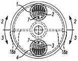
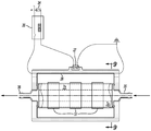
도 1~도 6은 열원(heat source)으로서 엔진 냉각수(또는 다른 적절한 유체)를 사용하는 워셔액 히터(washer fluid heater)(96)의 구성을 나타낸다. 이 구성은 또한 8개의 최소 구성 부품을 나타낸다. 1-6 show the configuration of a
데워진 엔진 냉각수는 주변 입구 호스 바브(off center inlet hose barb)(1)로부터 외측 하우징 챔버(outer housing chamber)(2)를 거쳐 히터의 반대쪽 단부(22)까지 흐르며, 반대쪽 핀 모양의 반환형 형태의 외부 열전달 챔버(3)로 방향을 바꿨다가, 다시 주변 출구 호스 바브(4)로 되돌아간다. 외측 핀 모양의 반 환형부(outer finned half annuli)(2, 3)는 핀 모양의 환형부의 전체 길이에 대한 선형 접촉 포인트(linear contact point)(18)에서 그리고 냉각수 바브 단부 댐(collant barb end dam)(18a)에서 밀봉되어 분리되어 있다. 차가운 워셔액(5)은 히터의 한쪽에 있는 중심측 입구 바브(on-center inlet barb)(6)로 들어가서 내측 핀형 열전달 챔버(7)를 통해 반대쪽 중심측 가열 워셔액 출구 바브(9)까지 매우 균일하게 분사되어 흐르는데, 이 열전달 챔버(7)는 대응하는 핀형의 매우 근접하고 균일한 간격, 즉 대략 0.010 인치의 일정한 간격을 가진 중심 코어(8)를 가진다. 중간 외측 핀형/내측 핀형 챔버(10)는 높은 열 전도성을 갖는 알루미늄 압출 구성이며, 가열 유체(예를 들어, 워셔액) 흐름 열 전달 챔버(7)를 부분적으로 형성하고, 가열할 세척용 유체의 소스, 워셔 펌프, 저장부(11) 및 체크 밸브(12)와 유체 노즐(13, 13a)(도 7 참조) 사이에 일렬로 유체 흐름이 가능하도록 배치된다. 코어(8)는 이러한 인클로저(10) 내에 배치되어 그 내부를 거의 완전하게 채우며, 4개의 길이방향의 중심에 위치된 핀 끝 부분 접촉 포인트(fin tip contact point)(14)에 의해 정확하게 위치설정되고, 열을 전도하는 내측 하우징의 길이방향 벽(10a)과 입구(15) 및 출구(16) 단부에서의 코어 표면의 균일하고 밀집된 간격(예를 들어, 0.010 인치)을 유지할 수 있어서, 매우 작은 용량 워셔액 흐름 경로로 열을 전도하는 일정한 두께의 유체 흐름 챔버(7)의 형성을 완료할 수 있다. 중심 코어(8)는 높은 열 전도성 재료로 구성해도 되고, 간단히 알루미늄 압출 구성으로 해도 되며, 축열체로서 기능할 수 있고, 내부가 비어 있어도 되고, 밀봉되어(도시하지 않음) 열적 상 변화 재료(PCM: phase change material)를 포함해서 히터 초기 출력을 증가시킬 수 있다. 열을 전달하는 내측 하우징의 길이방향 벽(10a)은 평면의 원형 모양부터 열 전도 면적을 증가시키기 위한 핀형(finned)의 원형 단면까지의 형태를 가질 수 있으며, 코어(8)의 단면은 내측 하우징의 열 전도성 내벽(10a)의 형태보다 약간 작고 비슷하다. 이러한 구성은, 균일하게 매우 얇은(예를 들어, 0.010 인치) 워셔액 흐름 채널 열 전도 챔버(7)를 제공하고, 이에 의해 강제 대류 펌프식 워셔액으로, 워셔액 입구(15)로부터 워셔액 출구(16)까지 매우 얇고 매우 낮은 열적 저항 유체 경계층(0.005 인치 두께보다 작다)을 만든다. The warm engine coolant flows from the off center inlet hose barb (1) through the outer housing chamber (2) to the opposite end (22) of the heater. The direction is changed to the
중간 외측 핀형/내측 핀형 부재(10)의 외측 표면(17)은 워셔액 내부 챔버 인클로저(10)와 오링 시일(O-ring seal)(15a, 16a)을 갖는 바브 단부 캡(barbed end cap)(6, 9)을 밀봉하는 외측 하우징(21)과 함께 엔진 냉각수용의 제2 유체 흐름 챔버(33)를 형성한다. 중간 외측 핀형/내측 핀형 부재(10)의 외측 표면(17)은 밀집되고 균일한 간격을 가진 다수의 열 전도성 핀을 포함하는 형상을 가지며, 이들 핀 모두는 밀접한 핀 끝 부분 간격(close fin tip clearance)(31)을 유지하거나, 외측 하우징(21)의 안쪽 벽(32)과 접촉하도록 되는데, 예외적으로 외측 하우징(21)의 안쪽 면과 포인트(18)에서 길이방향으로 항상 밀봉되어 접촉하는 반대 방향을 향하는 2개의 핀은 그렇게 되어 있지 않아서, 댐(18a)과 연결되어 핀형 반환형 흐름 채널(finned half annulus flow channel)(2, 3)을 형성하고, 냉각수가 입구 호스 바브(6)로부터 외측 하우징 챔버의 절반(2)을 통해 반대쪽 단부(22)까지 흐르고 다시 바깥쪽으로 외측 하우징 챔버의 대향하는 절반(3)을 통해 냉각수 출구 호스 바브(4)까지 흐른다. 외측 하우징(21)은 통상적으로 나일론 또는 폴리페닐린 설파이드(PPS)로 채워진 유리섬유와 같은 열 전도성이 낮고 강도가 높은 자동차용 냉각 시스템 재료로 구성되며, 알루미늄으로 된 중간 부재(10)의 외측 핀에 대해 밀집된 간격(예를 들어, 0.010 인치~0.020 인치)과 유사한 일체형 핀(integral fin)(23)을 가질 수 있다. 외측 하우징(21)은 높은 압력과 고열의 열원 시스템에서 적용할 수 있는 히터를 요구하는 것과 같은 필요에 따라 높은 강도의 금속으로 구성될 수 있다. 압력이 매우 높고 온도가 높은, CO2 열 펌프와 같은 열원의 경우, 이러한 압력을 양호하게 유지하기 위해, 가열(CO2) 유체용으로 내측 핀형 흐름 챔버를 사용하고 가열할 낮은 압력(워셔액) 유체용으로 외측 핀형 챔버를 사용할 수 있다. 외측 하우징 냉각수용의 입구 바브(1) 및 출구 바브(4)는, 도 2를 참조하면, 엔진으로부터 나오거나 되돌아가는 캐빈 히터 라인(cabin heater line)과 바람직하게는 일렬로 된 엔진 냉각수 라인과 연결하기 위한 것이다. The
알루미늄 부품은 열 전달 특성을 최소로 저하시키는 부식 방지를 위해 필요에 따라 양극 산화 처리되거나 코팅된다. Aluminum parts are anodized or coated as needed to prevent corrosion that minimizes heat transfer properties.
히터는 바람직하게는 워셔액 입구를 상단에, 워셔액 출구를 하단에 수직 위치로 설치해서, 노즐이나 유체 전달 와이퍼 블레이드 대신에 유체 열 퍼징(fluid thermal purging)이 저장부(reservoir)로 되돌아가는 것을 용이하게 할 수 있다. 또한, 냉각수 입구 및 출구 바브는 공기 포집(air entrapment)을 방지하기 위해 수직으로 설치하는 것이 바람직하다. The heater preferably has the washer fluid inlet at the top and the washer fluid outlet at the bottom in a vertical position to facilitate fluid thermal purging back into the reservoir instead of nozzles or fluid transfer wiper blades. can do. In addition, the coolant inlet and outlet barbs are preferably installed vertically to prevent air entrapment.
3개 이상의 유체를 제공하거나, 가열 유체를 내측 흐름 챔버로 스위칭하고 가열할 유체를 외측 흐름 챔버로 스위칭함으로써, 원형이 아닌 평면형으로 하는 것과 같이 다른 유사한 효과를 갖는 구성도 가능하다. 또한, 외측 흐름 챔버는 열 교환기(heat exchanger)의 반대쪽 끝에 입구 및 출구를 가질 수 있다. By providing three or more fluids, or by switching the heating fluid to the inner flow chamber and the fluid to be heated to the outer flow chamber, configurations with other similar effects are possible, such as being planar rather than circular. The outer flow chamber may also have an inlet and an outlet at the opposite end of the heat exchanger.
종래의 워셔/와이퍼 스위치를 작동시키면, 워셔액은 종종 비어 있는 상태에 있으며 대략 158℉의 알콜성의 낮은 끓는 점으로부터 퍼징에 의해 비어 있는 매우 작은 용량의 내측 워셔액 가열 챔버(7)를 신속하게(1초 이하) 채우고, 워셔액은 더 높은 온도에서 항온식으로 조절되는 대략 대략 200℉의 엔진 냉각수에 의해 가열된다. 실질적으로 가열된 유체는 종래의 노즐(13) 또는 본 발명의 바람직한 와이퍼 스퀴지 통합 노즐(13a)로부터 즉각적으로 분사되어, 윈드실드 및 와이퍼 블레이드에 대하여 가열한 워셔액의 제빙 및 세척 동작을 연속해서 행한다. When the conventional washer / wiper switch is activated, the washer fluid is often empty and quickly (one second) the very small capacity inner washer
히터는 매우 높은 열 전달률(heat transfer rate)을 갖기 때문에, 열 회복 시간(heat recovery time)은 촘촘히 반복되는 제빙/세척 사이클이 요구될 때에 실질적으로 즉각적이 된다. 세척이 정지된 경우, 히터와 노즐 사이에 남아 있는 유체는 체크 밸브(check valve)(12)에 의해 워셔 라인(washer line)에 남게 되고, 워셔 히터에 있는 매우 소량의 워셔액은 낮은 알콜성 워셔액 끓는점 온도에 의해 곧바로 퍼지(purge)되는데, 워셔 저장부(washer reservoir) 쪽으로 다시 퍼지되고, 이에 의해 퍼지된 유체 액이 보존되고, 칼슘/미네랄 저장과 캐빈 히터 냉각수 순환로(cabin heater coolant circuit)로부터 임의의 상당한 열적 에너지 유입이 중단된다. Since the heater has a very high heat transfer rate, the heat recovery time is substantially immediate when a tightly repeated ice making / cleaning cycle is required. When washing is stopped, the fluid remaining between the heater and the nozzle is left in the washer line by a
동결 온도에서 엔진이 정지될 때, 냉각으로부터의 열적 수축(thermal contraction)에 의해 워셔액이 매우 작은 워셔액 히팅 챔버(7)로 다시 유입될 수 있다. 부동액의 부족에 의한 임의의 후속되는 동결은 이전의 극소량의 함유된 유체의 극소량의 동결 팽창에 의해 유체 히터를 기본적으로 손상되지 않은 상태로 유지할 것이다. When the engine is stopped at the freezing temperature, the washer fluid can be introduced back into the very small washer
다른 바람직한 실시예는 엔진 냉간 시동 조건에서의 매우 신속한 제빙과 전기 동력식 차량에 사용하기 위한 열원(heat source)으로서 전기 가열 요소를 포함한다. 상기 설명한 실시예와 구성과 기능이 유사하다는 것이 명백할 것이다. Another preferred embodiment includes an electrical heating element as a heat source for use in electrically powered vehicles and for very rapid deicing in engine cold start conditions. It will be apparent that the construction and function are similar to the embodiments described above.
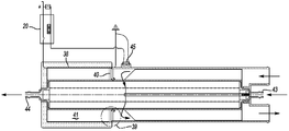
도 8~도 12는 대략 600 와트 등의 비교적 낮은 소비 전력을 가지며, 절연된(24) 축열 열 전도체(25)를 포함하는 항온 제어방식(27)의 전기 워셔액 히터의 바람직한 실시예 구성을 나타낸다. 전기 가열 요소(26)는 양극 산화 처리되고 전기적으로 절연된 축열 알루미늄 부재(25)와 밀접하게 접촉되어 이를 둘러싼다. 차량의 정상적인 점화 작동 스위치(34), 또는 다른 적절한 제어장치는, 주위 온도가 대략 40℉ 이하로 되고, 열 저장 부재가 400℉ 내지 500℉ 사이로 가열되고, 절연됨으로써, 400℉ 내지 500℉의 평형 열적 부재 온도가 높은 히스테리시스 40℉ 센싱 서모스텟(sensing thermostat)에 의해 유지 및 기본적으로 제어되도록 절연되는 경우, 높은 히스테리시스 서모스탯(27) 및 600 와트의 파워 릴레이(20)와 함께 전기 가열 요소(26)에 전원을 공급한다. 표준 스티어링 칼럼이 설치된 스위치에 의해 워셔 펌프가 동작할 때에, 차가운 유체는 히터의 입구 바브(35)로 들어가고, 도 1 내지 도 6에서 언급한 것과 유사한 내측 핀형 및 코어드(8b) 가열 챔버(7a)에서 즉각적으로 가열되며, 열 저장 부재(25)는 즉각적인 열원으로서 작용한다. 실질적으로 가열된 유체는 히터 출구 바브(36)로부터 분사되어 노즐로 진행한다. 에어 갭(37)은 최대 유체 출구 온도를 제어하기 위해 열 저장 부재로부터 열 전달을 조절하기 위한 크기를 갖는다. 8-12 show a preferred embodiment configuration of an electric washer fluid heater of constant
도 13 및 도 14는 도 1 내지 도 6에 나타낸 것과 유사한 열원으로서 엔진 냉각수를 가지며, 즉시 열원으로서 열적으로 절연되고 열원 열적 장벽 및 에어갭(40)에 의해 분리된 축열 열 전도성 부재를 포함하는 도 3과 관련해서 기재된 것과 유사한, 예를 들어 600 와트의 비교적 낮은 소비 전력을 갖는 전기 워셔액 히터와 존(39)에서 통합해서 결합되는 조합 워셔액 히터의 바람직한 실시예 구성을 나타낸다. 이미 설명한 도 8에서와 같이, 전기 가열 요소(38)는 열적 전도성을 가지며 양극 산화되고 이에 따라 전기적으로 절연된 알루미늄 열 저장 부재(41)와 밀접하게 접촉해서 이를 둘러싼다. 대략 40℉의 항온적으로 감지된 주위 온도 이하에서 엔진 냉간 시동할 때에, 전기 가열 요소(38)는 열 저장 부재(41)를 가열하고, 열적 배리어(40)에 의해 현재 차가운 엔진 냉각수 통로로부터 열적으로 분리된다. 열 저장 부재의 전기 가열 및 엔진 냉각수 예열의 짧은 시간(대략 3, 4분) 후에, 그리고 종래의 스티어링 칼럼이 설치된 워셔 스위치에 의해 워셔 펌프가 작동할 때에, 차가운 워셔액은 히터의 입구(43)로 들어가서, 현재 약간 데워진 엔진 냉각수 존을 통과하고 현재 상당히 가열된 전기적 가열식 열 저장 부재(41) 존으로 들어가고, 즉시 그리고 상당히 가열된 후, 출구 바브(44)로부터 분사되고 충분한 열적 에너지로 윈드실드를 세척해서, 30초 내에 윈드실드의 상당한 양의 성에를 제거할 수 있다. 서모스텟(45)은 대략 25℉의 온도 히스테리시스를 가지도록 구성되며 주위 및 엔진 냉각수 온도의 조합을 감지하도록 설치된다. 전기 히터는 엔진 냉각수가 대략 65℉를 초과할 때에 항온적으로 디스에이블될 것이며, 이후 히터의 엔진 냉각수 가열 부분은 전기적 가열 유입 없이 워셔액을 효과적으로 가열하기에 충분한 파워를 가질 것이다. 에어 갭(37)은, 도 3에 나타낸 바와 같이, 히터의 전기적 열 저장 부재로부터 기존의 최대 유체 온도를 조절하는 데에 사용될 수 있다. FIGS. 13 and 14 have regenerative thermally conductive members having an engine coolant as a heat source similar to that shown in FIGS. 1 to 6, immediately thermally insulated as a heat source and separated by a heat source thermal barrier and
도 15 및 도 16은 도 13에 나타낸 것과 유사지만, 3500 와트와 같이 비교적 높은 소비 전력을 가지며, 열 저장 부재가 없는, 전기 워셔액 히터의 바람직한 실시예 시스템 구성을 나타낸다. 또한, 흐름 센싱 홀 효과 스위치(28)(또는 대안으로서 자석/리드 스위치 흐름 센서)가 도시되어 있으며, 이 스위치는 홀 효과 전자 증폭기(51)(또는 리드 스위치 릴레이)와 조합되어, 높은 전류 솔레노이드 스위치(46)를 작동시켜 가열 전류를 저항 가열 요소(30)에 공급한다. 서모스텟(49)에 의해 감지되는 대략 40℉ 이하의 주위 온도에 의해 그리고 점화 작동 스위치에 의해 엔진 냉간 시동을 할 때와 표준 스티어링 칼럼이 설치된 워셔 스위치를 운전자가 작동시킬 때에, 차가운 유체가 워셔액 히터 입구 바브(50) 안으로 펌핑되며, 스프링이 장착된 피스톤 셔틀(47) 자석(48)을 홀 효과 센서(28)의 근접한 부근(48a)까지 이동시키고, 센서(28)가 홀 센서 프로세서(51)를 트리거하고, 높은 전류 솔레노이드 스위치(46)를 근접시켜 높은 암페어의 가열 전류를 가열 요소(30)에 제공할 수 있도록 한다. 이에 의해, 워셔액은 즉각적으로 그리고 실질적으로 가열되고 히터 출구 바브(52)로부터 분사되어, 충분한 열 에너지를 포함시켜, 엔진 냉간 시동부터 30초 내에 충분히 윈드실드의 성에를 제거할 수 있다. 이것은 매우 높은 파워의 전기 부하(electrical load)이기 때문에, 매우 제한된 전기적 공급 능력을 가진 차량의 경우, 주행 중인 아닌 냉간 엔진 시동의 경우에 사용하는 것이 적절할 수 있으며, 중립 시동 스위치에 의해 그라운딩함으로써 주행 동안 히터를 자동으로 디스에이블할 수 있다. 또한, 전기 시스템을 양호하게 보호하기 위해, 저전압 디스에이블 센스(51a)를 사용해서, 차량 시스템 전압이 너무 낮으면 히터가 턴온되는 것을 방지한다. 필터 스크린(filter screen)(53)은 흐름 센싱 셔틀 스위치(flow sensing shuttle switch)를 셔틀 이동을 방해하는 외부 입자로부터 보호하기 위한 것이다. 예를 들어, 파워 릴레이 접촉의 용접(welding)에 의해 드물게 생길 수 있는 과열(overheating)에 대해 자동안전 보호를 위한 열 퓨즈 조인트(thermal fuse joint)(54)가 도시되어 있다. 본 기술분야의 당업자라면, 본 명세서에 개시된 상당한 수준의 전기기계 제어 시스템은 이러한 워셔액 히터의 기능적 효능을 실질적으로 향상시키지 않고도, 동일 또는 유사한 로직을 사용하여 더 완전한 전자 소프트웨어에 기반을 둔 제어로 효과적으로 대체될 수 있다. 사실상, 어떤 차량은 전자 바디 컨트롤러(electronic body controller)와 같이 보드 상에 제어 부품을 이미 구비하고 있을 수 있으며, 이러한 워셔액 히터에 도움이 되도록 저비용으로 사용될 수 있다. 15 and 16 show a preferred embodiment system configuration of an electric washer fluid heater similar to that shown in FIG. 13 but with a relatively high power consumption, such as 3500 watts, and without a heat storage member. Also shown is a flow sensing Hall effect switch 28 (or alternatively a magnet / lead switch flow sensor), which is combined with a Hall effect electronic amplifier 51 (or a reed switch relay) to provide a high current solenoid switch. (46) is actuated to supply a heating current to the resistive heating element (30). When the engine is cold started by an ambient temperature of approximately 40 ° F or less sensed by the
도 17 및 도 18은 3500 와트와 같은 비교적 높은 소비 전력을 가지며 열 저장 부재를 포함하지 않는 전기 워셔액 히터와 통합적으로 결합된 열원으로서 엔진 냉각수를 갖는 조합 워셔액 히터의 바람직한 실시예 구성을 나타낸다. 또한, 흐름 센싱 홀 효과 셔틀(flow sensing Hall Effect shuttle)(59)이 설치된 자석(56) 작동식 센서(57)(대안으로서, 리드/자석 스위치)가 도시되어 있으며, 이 센서는 홀 효과 전자 증폭기(55)(또는 리드 릴레이)와 함께, 높은 전류 솔레노이드 스위치(58)를 작동시켜 가열 전류를 가열 요소에 공급할 수 있다. 이러한 히터는 예외적으로 엔진이 대략 40℉ 이하에서 냉간 시동을 시작하자마자 히터가 즉각적으로 활성화되는 것을 제외하고는, 도 4에 개시된 것과 동일한 방식으로 동작하며, 시스템은 냉간 엔진을 시동하고 30초 이내에 통상 윈드실드의 성에를 제거할 수 있을 것이다. 17 and 18 show a preferred embodiment configuration of a combination washer fluid heater with engine coolant as a heat source integrally coupled with an electric washer fluid heater that has a relatively high power consumption, such as 3500 watts and does not include a heat storage member. Also shown is a
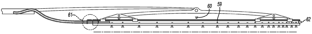
도 19는 바람직한 실시예의 유체 분사 와이퍼 블레이드를 나타내는데, 이 블레이드에선, 와이퍼 암 피벗(wiper arm pivot)으로부터 더 바깥쪽을 향해 끝으로 갈수록 더 밀접한 간격을 가진 반대쪽 스태거드 제트(staggered jet)(59)가 거의 완벽하게 균일한 막의 워셔액을 윈드실드의 세척 영역으로 분사하며, 블레이드 구조의 각각의 피벗 조인트(pivot joint)에 대해 전용의 유체 제트(60)를 포함하고, 블레이드의 바깥쪽 끝 부분에 와이퍼 블레이드 유체 공급 호스 신속 연결 수단(61) 및 플러깅(plugging) 수단(62)을 포함한다. Fig. 19 shows a fluid jet wiper blade of the preferred embodiment, in which the opposite staggered jet (59) is spaced closer toward the end from the wiper arm pivot toward the outside. Sprays the wash fluid of the membrane almost completely uniform into the washing area of the windshield, and includes a
도 20 및 도 21은 와이퍼 블레이드 고무 스퀴지에서 힐(heel)부터 팁(tip)까지 끝으로 갈수록 더 밀집한 간격을 가진 구멍 패턴(orifice pattern)을 천공하기 위한 바람직한 제조 과정을 나타낸다. 연속적으로 진행되는 과정은 시퀴지 압출(squeegee extrusion)(77)을 모터 및 기어 구동식 천공 휠(74, 75, 76)에 공급한다(와이퍼 에지에 슬릿을 형성하기 전에, 본 기술분야에서 일반적으로 제조되는 것과 같이, 이중의 대향하는 시퀴지가 구성될 수 있지만 도시하지는 않음). 휠 외주(wheel perimeter)는 스퀴지의 최종적인 절단 길이에 대응하며, 시퀴지 천공 위치(squeegee piercing position)에서 다른 휠의 다른 포인트와 간섭하는 포인트가 없도록 위치된 천공 포인트를 포함한다. 휠(75, 76)의 스퀴지 컷오프 영역(79)은 휠(75)의 컷오프 블레이드와 휠(76)의 쿠션 안빌(cushioned anvil)로 구성되어, 컷오프 블레이드(80) 에지 첨예를 유지한다. 휠(75, 76)의 외주는 블레이드를 차량에 설치할 때에 도체가 이완 위치(relaxed position)로 되돌아갈 때 천공이 윈드실드를 향해 아래로 향하도록 유체 도관 홀(81)의 방향을 전환하도록 하는 형태를 갖는다. 천공 포인트(78)는 원하는 길이의 시퀴지 슬릿(squeegee slit)을 만들기 위한 형태를 갖는 블레이드가 바람직하다. 천공 휠(74)은 블레이드 프레임 조인트(blade frame joint)에 대한 제트를 만들기 위한 것이다. 20 and 21 illustrate a preferred manufacturing process for drilling an orifice pattern with a tighter spacing toward the end from the heel to the tip in the wiper blade rubber squeegee. A continuous process feeds a
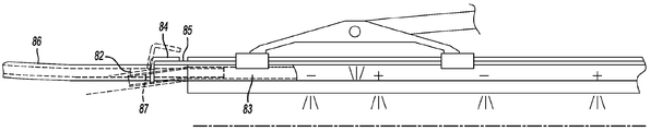
도 22 및 도 23은 와이퍼 블레이드 스퀴지의 힐에 워셔액 호스의 결합을 신속하게 연결/단절하는 바람직한 구성을 나타낸다. 경성(rigid)의 튜브(82)가 스퀴지 도관(83)에 미리 접착된다. 직각 개방 단부 클립(right angle open end clip)(84)은 통상의 가요성 스퀴지 금속 스파인(flexible squeegee metal spine)(85)에 용접된다. 호스(86) 연결은 튜브/스퀴지 힐을 아래쪽으로 휘고, 호스를 스퀴지 힐 단부에 대하여 맞닿도록 튜브 위에 놓고, 튜브 내에 매칭되는 넥크 처리된(necked) 다운 영역(87)과 정렬된 클립의 개방 단부까지 잡아채어, 심미적으로 호감을 주고 견고한 연결을 행하기에 편리하게 된다. 블레이드 교체에 대해, 단절(disconnect) 과정은 이러한 연결 과정의 반대로 하면 될 것이다. 22 and 23 show a preferred configuration for quickly connecting / disconnecting the washer fluid hose to the heel of the wiper blade squeegee. A
도 24 및 도 25는 블레이드 프레임(blade frame)(94)과 조립하는 동안 와이퍼 블레이드 스퀴지를 천공하기 위한 바람직한 과정을 나타낸다. 고정된 프로그램 레이저 헤드(88)는 레이저 빔(91)에 의해 천공 부분(89)을 고무 스퀴지(90)로 절단한다. 스퀴지 서포트 로드(squeegee support rod)(92)는 스퀴지 도관(squeegee conduit)을 통과하고 캐리지(carriage)(93)에 연결되어 천공 과정 중에 스퀴지가 똑바로 되도록 유지한다. 24 and 25 show a preferred procedure for drilling a wiper blade squeegee during assembly with a blade frame 94. The fixed
도 26은 윈드실드의 안쪽 면에 대해 작고 제한된 공기 흐름 덕트와 조합하여 기본적으로 제빙을 행하고, 대시 패널(dash panel)에 정상적으로 포함된 통상적인 대규모 공기 흐름 디프로스터 덕트를 제거하기 위한 가열식 워셔 와이퍼 시스템을 사용하는 차량의 완전한 윈드실드 제빙/김서림 방지 시스템의 바람직한 실시예를 나타낸다. 이에 의해 생기는 대시 패널 내의 여유 공간은 대시 패널 공간이 다른 것에 사용할 수 없는 경우 다른 부품을 패키징하는 데에 사용될 수 있다. 또한, 뜨거운 공기 디프로스터 에너지가 크게 감소되었기 때문에, 많은 캐빈 열(cabin heat)이 운전자에게 제공될 수 있다. 가열된 워셔액 분사 와이퍼 블레이드(70)는 열원(72)을 가진 소형의 저흐름 제빙 및 김서림 제거 덕트(71)가 차량의 정상적인 작동 중에 깨끗한 윈드실드를 유지하면서, 신속하게 그리고 높은 열 효율로 윈드실드의 외면에 처음에 생긴 무거운 성에를 제거할 수 있다. 이 덕트는 윈드실드의 내부 면의 김서림을 제거하는 데에 도움을 주기 위해 공기 조화 시스템으로부터 제습 공기(dehumidified air)를 제공할 수도 있다. FIG. 26 is a heated washer wiper system for basic deicing in combination with small, limited airflow ducts to the inner side of the windshield and to remove conventional large-scale airflow defroster ducts normally included in a dash panel. A preferred embodiment of a complete windshield de-icing / anti-fog system of a vehicle using The resulting free space in the dash panel can be used to package other parts when the dash panel space is not available for anything else. Also, because cabin air defroster energy has been greatly reduced, many cabin heat can be provided to the driver. The heated washer fluid
귀환 공기 덕트(returing air duct)(73)를 윈드실드의 상단 내부 표면에 사용할 수 있으며, 제빙/김서림 방지 공기가 위드실드의 상부 영역에 들러붙도록 해서 그렇지 않았으며 캐빈으로 들어가고 윈드실드의 상부 영역의 클리어링을 방해할 이러한 공기를 최소로 하기 위해, 헤드라이너(headliner) 및 윈드실드 헤더 프레임 구조체의 도관 형상을 이용하여 비용을 절감할 수 있다. A returning
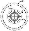
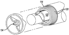
도 27 내지 도 30을 참조하면, 또 다른 워셔액 히터(100)가 도시되어 있다. 히터(100)는 길고 가늘며 전체적으로 원통형인 하우징 챔버(104)를 형성하는 하우징(102)을 포함한다. Referring to Figures 27 to 30, another
바람직하게, 하우징(102)은 실질적으로 원통형이며 개방 단부(110, 112)를 각각 구비하는 2개의 하우징 쉘(housing shell)(106, 108)로 이루어져 있다. 하우징 쉘(106, 108)의 각각의 개방 단부(110, 112)는 회전 용착(spin welding)과 같은 임의의 통상적인 방식으로 서로 고정되어 있다. Preferably,
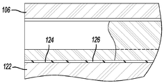
하우징 챔버(104) 내에는 전체적으로 튜브형이며 원통형인 서브하우징(114)이 위치하며, 이 서브하우징에 의해, 하우징 챔버(104)는 서브하우징(114)과 하우징(102) 사이에 형성되는 환형의 외측 하우징 챔버(116)와, 서브하우징(114) 내에 형성되는 내측 하우징 챔버(118)로 나누어진다. 서브하우징(114)은 열 전도성 재료, 바람직하게는 알루미늄 등의 금속으로 이루어지며, 외주방향으로 간격을 두고 형성된 다수의핀(fin)(120)(도 28 참조)을 포함한다. 이 핀은 외측 하우징 챔버(116)를 전체적으로 반경 방향으로 가로지르면서 연장되어 있다. 바람직하게, 서브하우징(114)은 금속 압출(metal extrusion)로 구성된다. Within the
도 28 내지 도 30을 참조하면, 내측 하우징 챔버(118) 내에 원통형의 코어(122)가 위치한다. 이 코어(122)는 코어(122)의 둘레로 외주방향으로 간격을 두고 형성된 다수의 스탠드오프(standoff)(124)를 포함한다. 스탠드오프(124)는 길고 가늘며 코어(122)의 길이방향을 따라 연장되는 것이 바람직하다. 스탠드오프(124)는 코어(122)를 내측 하우징 챔버(118) 내에서 중심에 오도록 함으로써, 얇고 바람직하게는 균일한 환형 챔버(126)가 코어(122)와 서브하우징(114) 사이에 형성된다. 28 to 30, a
도 28-도 30에 도시된 환형 챔버(126)는 튜브형이며 원통형이다. 그러나, 이와 달리 환형 챔버(126)가 도 10-도 12에 도시된 것과 같은 교차방식의 핀(interlaced fin)을 포함하는 것도 가능하다. The
코어(122)는 알루미늄과 같은 열 전도성 재료로 이루어진다. 이에 따라, 코어(122)는 신속하게 가열되고 열 에너지를 저장할 수 있다.
스탠드오프(124)의 높이는 환형 챔버(126)의 반경 방향의 두께를 규제한다. 도 29에 나타낸 바와 같이, 환형 챔버(126)의 반경 방향의 두께는 서브하우징(114)의 내부 사이즈에 비해 매우 작다. 코어(122)는 챔버(126)의 부피에 대한 챔버(126)의 침수 벽 표면의 면적의 비율이 적어도 700 m2/m3이고, 바람직하게는 2000 m2/m3을 초과하는 크기를 갖는다. The height of the
도 29에 나타낸 바와 같이, 윈드실드 워셔액 입구(130)는 하우징(102)의 일단부(133)에 부착되며, 마찬가지로 윈드실드 워셔액 출구(134)는 하우징(102)의 타단부(132)에 부착된다. 윈드실드 워셔액 입구(130) 및 출구(134)는 환형 챔버(126)의 대향하는 단부에 유체 흐름이 가능하도록 개방되어 있다. 워셔액 입구(130) 및 워셔액 출구(134)는 서브하우징(114)의 개방 단부를 가로질러 밀봉되어 연장된 캡(cap)(138, 140)을 포함한다. 입구(130) 및 출구(134)와 하우징(102) 사이에서의 유체 밀봉(136)에 의한 이러한 밀봉은 입구(130) 및 출구(134)를 하우징(102)에 유체 밀봉하고, 외측 하우징 챔버(104)로부터 환형 챔버(126)를 유체 격리시킨다. 단부 캡(138, 140) 상의 오목부(125)는 단부 캡(138, 140)을 코어(122)로부터 이격시키며, 입구(130) 및 출구(134)와 환형 챔버(126) 사이에서의 유체 흐름을 구축함으로써, 입구(130)로부터 챔버(126)를 통해 출구(134)로 빠져나가는 유체 흐름을 형성하게 된다. As shown in FIG. 29, the windshield
도 27 및 도 29를 참조하면, 엔진 냉각수 입구(150)가 하우징(102) 내에 형성되고, 외측 하우징 챔버(104)에 대해 개방되어 있다. 마찬가지로, 냉각수 출구(152)도 하우징(102)에 설치되어 있고, 냉각수 입구(150)로부터 이격된 위치에서 외측 하우징 챔버(104)에 대해 개방되어 있다. 도면에 도시된 바와 같이, 냉각수 입구(150) 및 냉각수 출구(152)는 하우징(102)의 동일한 단부(133)에 설치된다. 그러나, 냉각수 입구(150) 및 냉각수 출구(152)는 본 발명의 범위를 벗어남이 없이 하우징(102)의 반대쪽 단부에 설치해도 된다. 27 and 29, an
선택적으로, 서브하우징(114)의 내부로 파편(debris)이 유입되는 것을 방지하기 위해 필터를 워셔액 입구(13)와 연결시킬 수 있다. Optionally, a filter may be connected with the
동작 중에, 윈드실드 와이퍼 워셔액 입구(130)는 대부분의 차량에 있는 윈드실드 워셔액 펌프와 같은 가압식 윈드실드 워셔액의 소스에 연결된다. 윈드실드 워셔액 출구(134)는 차량에 설치된 분사 제트(spray jet)에 그리고 차량 윈드실드에 직접 유체 흐름이 가능하도록 연결되거나, 앞서 설명한 것과 같은 윈드실드 와이퍼 블레이드에 유체 흐름이 가능하도록 연결된다. 따라서, 윈드실드 워셔액 펌프를 작동시키면, 윈드실드 워셔액이 워셔액 입구(130)로 들어가서 환형 챔버(126)를 통해 워셔액 출구(134)로 나오도록 펌핑된다. In operation, the windshield
동시에, 가열된 엔진 냉각수 워셔액이 냉각수 입구(150)로 들어가서 외측 하우징 챔버(104)를 통해 냉각수 출구(152)로 흐른다. 엔진 냉각수의 일부 누출(leakage)이, 하우징(102)의 길이를 따라 길이방향으로 흐르지 않고, 냉각수 입구(150)로부터 냉각수 출구(152)로 직접 흐른다고 해도, 하우징(102)를 통해 흐르는 대다수의 냉각수는, 서브하우징(114)에 있는 핀(116)에 의해, 화살표(154)로 나타낸 바와 같이, 하우징(102)의 일단부(133)로부터 타단부(132)까지 흐른다. 하우징의 단부(133)에 있는 유체 댐(fluid dam)(155; 도 31 참조)은 단부 캡(138)에 맞닿아서, 냉각수 입구(150)로부터 냉각수 출구(152)로 직접 유체가 흐르는 것을 방지한다. At the same time, the heated engine coolant washer fluid enters the
엔진 냉각수가 전체적으로 외측 하우징 챔버(104)를 통해 흐르도록 하고 냉각수 입구(150)로부터 냉각수 출구(152)로 직접 누출되는 유체를 최소화하기 위해, 핀(120)과 하우징(102) 사이에 억지 끼워 맞춤(interference fit)을 형성하는 것이 바람직하다. An interference fit between the
동작에 있어서, 엔진 냉각수로부터의 열은 서브하우징(114)에 의해 전달되어, 환형 챔버(126) 내의 윈드실드 워셔액을 가열시킨다. 챔버(126)의 부피에 대한 환형 챔버(126)의 젖음 면적(wetted area)의 비율이 상당히 높기 때문에, 환형 챔버(126) 내의 윈드실드 워셔액의 가열이 신속할 뿐만 아니라, 거의 최대로 될 수 있다. 사실상, 워셔액 출구(134)로부터 나오는 윈드실드 워셔액의 온도는 엔진 냉각수의 온도와 근사치가 된다. In operation, heat from the engine coolant is transferred by the sub-housing 114 to heat the windshield washer fluid in the
실제의 사용에서, 윈드실드 워셔 시스템을 사용한 후에, 환형 챔버(126) 내에 포함된 윈드실드 워셔액은 증발되어 저장부로 되돌아갈 것이다. In practical use, after using the windshield washer system, the windshield washer fluid contained in the
본 발명에 대하여 설명하였지만, 본 발명은 자동차의 윈드실드 및 와이퍼에 대하여 제빙 및 제상을 신속하고 효과적으로 행하는 간단하고 매우 효과적인 가열식 윈드실드 워셔액 시스템을 제공한다는 것을 알 수 있을 것이다. 본 발명에 대하여 개시하였지만, 당업자라면 청구범위에 의해 정의된 본 발명의 사상으로부터 벗어남이 없이 많은 변형이 가능할 것이다. Although the present invention has been described, it will be appreciated that the present invention provides a simple and highly effective heated windshield washer fluid system for quickly and effectively deicing and defrosting a windshield and a wiper of an automobile. Although the present invention has been described, many modifications will be possible to one skilled in the art without departing from the spirit of the invention as defined by the claims.
Claims (25)
하우징 챔버(housing chamber)의 경계를 규정하는 2개의 단부(end)를 갖는 하우징;
상기 하우징 챔버 내에 위치하며 열 전도성 재료로 이루어지는 서브하우징(subhousing)으로서, 상기 하우징 챔버를 상기 하우징과 상기 서브하우징 사이의 외측 하우징 챔버(outer housing chamber)와, 상기 서브하우징 내부의 내측 하우징 챔버(inner housing chamber)로 나누는 서브하우징;
상기 내측 하우징 챔버 내에 위치하며, 상기 서브하우징과의 사이에 환형 챔버(annular chamber)를 형성하는 코어(core);
상기 하우징 상에 위치하여 상기 환형 챔버의 일단부에 대해 개방된 워셔액 입구(washer fluid inlet) 및 상기 하우징 상에 위치하여 상기 환형 챔버의 타단부에 대해 개방된 워셔액 출구(washer fluid outlet); 및
상기 외측 하우징 챔버에 대해 개방된 엔진 냉각수 입구(engine coolant inlet) 및 상기 냉각수 입구로부터 이격된 위치에서 상기 외측 하우징 챔버에 대해 개방된 엔진 냉각수 출구(engine coolant outlet)
를 포함하며,
대부분의 냉각수가 상기 엔진 냉각수 입구로 들어가서 상기 외측 하우징 챔버를 거쳐 상기 엔진 냉각수 출구로 흐르는 것을 특징으로 하는 윈드실드 워셔액 히터. In the windshield washer fluid heater,
A housing having two ends defining a boundary of the housing chamber;
A subhousing located within the housing chamber and made of a thermally conductive material, the housing chamber comprising an outer housing chamber between the housing and the subhousing and an inner housing chamber inside the subhousing. a subhousing divided into a housing chamber;
A core located within the inner housing chamber, the core defining an annular chamber between the sub-housing;
A washer fluid inlet located on the housing and open to one end of the annular chamber and a washer fluid outlet located on the housing and open to the other end of the annular chamber; And
An engine coolant inlet open to the outer housing chamber and an engine coolant outlet open to the outer housing chamber at a position spaced apart from the coolant inlet.
Including;
A windshield washer fluid heater, characterized in that most of the coolant enters the engine coolant inlet and flows through the outer housing chamber to the engine coolant outlet.
상기 코어는 상기 환형 챔버의 부피(volumne)에 대한 상기 환형 챔버의 젖음 면적(wetted surface area)의 비율이 700 m2/m3를 초과하는 크기를 갖는, 윈드실드 워셔액 히터. The method of claim 1,
And the core has a size such that the ratio of the wetted surface area of the annular chamber to the volume of the annular chamber exceeds 700 m 2 / m 3 .
상기 워셔액 입구는 상기 하우징의 일단부에 위치하며, 상기 워셔액 출구는 상기 하우징의 타단부에 위치하는, 윈드실드 워셔액 히터. The method of claim 1,
And the washer fluid inlet is located at one end of the housing and the washer fluid outlet is at the other end of the housing.
상기 엔진 냉각수 입구 및 상기 엔진 냉각수 출구는 상기 하우징의 일단부 상에서 외주방향으로 이격된 위치에 설치된, 윈드실드 워셔액 히터. The method of claim 1,
And the engine coolant inlet and the engine coolant outlet are installed at circumferentially spaced positions on one end of the housing.
상기 서브하우징은 상기 외측 하우징 챔버 내에 위치한 다수의 열 전도성 핀(heat conductive fin)을 포함하는, 윈드실드 워셔액 히터. The method of claim 1,
And the subhousing includes a plurality of heat conductive fins located within the outer housing chamber.
상기 서브하우징은 금속 압출(metal extrusion)로 구성된, 윈드실드 워셔액 히터. The method of claim 5,
And the sub-housing consists of metal extrusion.
상기 서브하우징은 하나의 알루미늄 압출로 구성된, 윈드실드 워셔액 히터. The method of claim 5,
And the sub-housing consists of one aluminum extrusion.
상기 하우징은 서로 밀봉되어 고정된 2개의 플라스틱 쉘(plastic shell)을 포하여 이루어진, 윈드실드 워셔액 히터. The method of claim 1,
And the housing comprises two plastic shells sealed and fixed to each other.
상기 코어는, 상기 코어를 상기 서브하우징과 동축이 되도록 위치시키는 다수의 간격을 두고 위치한 스탠드오프(standoff)를 포함하며, 상기 스탠드오프는 상기 환형 챔버의 반경 방향의 폭을 규정하는, 윈드실드 워셔액 히터. The method of claim 1,
The core includes a standoff positioned at a plurality of intervals for coaxially positioning the core with the sub-housing, wherein the standoff defines a radial width of the annular chamber. heater.
상기 환형 챔버의 반경 방향의 폭은 0.020 인치보다 작은, 윈드실드 워셔액 히터. The method of claim 1,
A windshield washer fluid heater, wherein the radial width of the annular chamber is less than 0.020 inches.
상기 코어는 상기 환형 챔버의 부피에 대한 상기 환형 챔버의 젖음 면적의 비율이 2000 m2/m3를 초과하는 크기를 갖는, 윈드실드 워셔액 히터. The method of claim 1,
And the core has a size such that the ratio of the wetting area of the annular chamber to the volume of the annular chamber is greater than 2000 m 2 / m 3 .
상기 환형 챔버의 일부의 주위에 배치되는 전기 히터(electric heater)를 더 포함하는 윈드실드 워셔액 히터. The method of claim 1,
A windshield washer fluid heater further comprising an electric heater disposed around a portion of the annular chamber.
상기 코어는 열 전도성 재료로 이루어지며 열 저장 부재(heat storage member)를 형성하는, 윈드실드 워셔액 히터. The method of claim 1,
Wherein said core is made of a thermally conductive material and forms a heat storage member.
상기 하우징은 상기 외측 하우징 챔버 내에 위치한 다수의 핀(fin)을 포함하는, 윈드실드 워셔액 히터. The method of claim 1,
And the housing comprises a plurality of fins located within the outer housing chamber.
하우징 챔버의 경계를 규정하는 2개의 단부를 갖는 하우징;
상기 하우징 챔버 내에 위치하며, 상기 하우징과의 사이에 환형 챔버(annular chamber)를 형성하는 코어(core);
상기 하우징 상에 위치하여 상기 환형 챔버의 일단부에 대해 개방된 워셔액 입구(washer fluid inlet) 및 상기 하우징 상에 위치하여 상기 환형 챔버의 타단부에 대해 개방된 워셔액 출구(washer fluid outlet); 및
상기 하우징의 주위에 배치된 전기 히터
를 포함하는 것을 특징으로 하는 윈드실드 워셔액 히터. In the windshield washer fluid heater,
A housing having two ends defining a boundary of the housing chamber;
A core located within said housing chamber, said core defining an annular chamber therebetween;
A washer fluid inlet located on the housing and open to one end of the annular chamber and a washer fluid outlet located on the housing and open to the other end of the annular chamber; And
An electric heater disposed around the housing
Windshield washer fluid heater comprising a.
상기 코어는 상기 환형 챔버의 부피에 대한 상기 환형 챔버의 젖음 면적의 비율이 700 m2/m3를 초과하는 크기를 갖는, 윈드실드 워셔액 히터. 16. The method of claim 15,
And wherein the core has a size such that the ratio of the wetted area of the annular chamber to the volume of the annular chamber is greater than 700 m 2 / m 3 .
상기 환형 챔버의 반경 방향의 폭은 0.020 인치보다 작은, 윈드실드 워셔액 히터. 16. The method of claim 15,
A windshield washer fluid heater, wherein the radial width of the annular chamber is less than 0.020 inches.
상기 코어는 상기 환형 챔버의 부피에 대한 상기 환형 챔버의 젖음 면적의 비율이 2000 m2/m3를 초과하는 크기를 갖는, 윈드실드 워셔액 히터. 16. The method of claim 15,
And the core has a size such that the ratio of the wetting area of the annular chamber to the volume of the annular chamber is greater than 2000 m 2 / m 3 .
상기 하우징의 온도를 미리 정해진 범위 내로 유지하는 상기 전기 히터용의 항온 제어식 전원(thermostatically controlled power supply)을 더 포함하는 윈드실드 워셔액 히터. 16. The method of claim 15,
And a thermostatically controlled power supply for the electric heater that maintains the temperature of the housing within a predetermined range.
상기 코어는 열 전도성 재료로 이루어지며 열 저장 부재(heat storage member)를 형성하는, 윈드실드 워셔액 히터. 16. The method of claim 15,
Wherein said core is made of a thermally conductive material and forms a heat storage member.
상기 환형 챔버를 통한 워셔액의 흐름이 없는 경우에 상기 전기 히터에 대한 전원의 연결을 끊는 스위치(switch)를 더 포함하는, 윈드실드 워셔액 히터. 16. The method of claim 15,
And a switch for disconnecting power to the electric heater when there is no flow of washer fluid through the annular chamber.
일단부는 폐쇄되어 있으며 타단부는 가압 유체(pressurized fluid)의 소스에 연결되도록 된 유체 도관(fluid conduit)을 구비하는 길고 가는 시퀴지(squeegee);
상기 스퀴지로부터 바깥쪽으로 연장된 와이퍼 에지(wiper edge); 및
상기 윈드실드 와이퍼 블레이드의 본체 내에 길이방향으로 간격을 두고 형성되어 있으며 상기 유체 도관까지 연장된 다수의 구멍(aperture)
을 포함하며,
상기 구멍은 상기 유체 도관의 한쪽 끝에서 다른 쪽 끝으로 갈수록 상기 구멍들 사이의 간격이 좁아지도록 된 것을 특징으로 하는 윈드실드 와이퍼 블레이드. In the windshield wiper blade,
A long thin squeegee having a fluid conduit adapted to be connected at one end to a source of pressurized fluid;
A wiper edge extending outwardly from the squeegee; And
A plurality of apertures formed longitudinally in the body of the windshield wiper blade and extending to the fluid conduit;
Including;
And the hole is configured such that the gap between the holes becomes narrower from one end of the fluid conduit to the other end.
상기 구멍은 레이저(laser)에 의해 형성된, 윈드실드 와이퍼 블레이드. The method of claim 22,
And the hole is formed by a laser.
상기 구멍은 펀치(punch)에 의해 형성된, 윈드실드 와이퍼 블레이드. The method of claim 22,
And the hole is formed by a punch.
상기 유체 도관을 워셔액 소스에 연결하는 퀵 커넥트 커플링(quick connect coupling)을 더 포함하는 윈드실드 와이퍼 블레이드. The method of claim 22,
And a quick connect coupling connecting the fluid conduit to a washer fluid source.
Applications Claiming Priority (4)
| Application Number | Priority Date | Filing Date | Title |
|---|---|---|---|
| US8957708P | 2008-08-18 | 2008-08-18 | |
| US61/089,577 | 2008-08-18 | ||
| US12/541,207 US8550147B2 (en) | 2008-08-18 | 2009-08-14 | Windshield washer fluid heater and system |
| US12/541,207 | 2009-08-14 |
Publications (1)
| Publication Number | Publication Date |
|---|---|
| KR20110044303A true KR20110044303A (en) | 2011-04-28 |
Family
ID=41680251
Family Applications (1)
| Application Number | Title | Priority Date | Filing Date |
|---|---|---|---|
| KR1020117006148A KR20110044303A (en) | 2008-08-18 | 2009-08-18 | Windshield washer fluid heater and system |
Country Status (7)
| Country | Link |
|---|---|
| US (1) | US8550147B2 (en) |
| EP (1) | EP2313295A4 (en) |
| JP (1) | JP5553071B2 (en) |
| KR (1) | KR20110044303A (en) |
| CN (1) | CN102123893B (en) |
| CA (1) | CA2732455A1 (en) |
| WO (1) | WO2010022032A2 (en) |
Cited By (2)
| Publication number | Priority date | Publication date | Assignee | Title |
|---|---|---|---|---|
| KR101252216B1 (en) * | 2011-10-17 | 2013-04-05 | 기아자동차주식회사 | Washer liquid heating apparatus and method in vehicle |
| KR20200001270A (en) * | 2018-06-27 | 2020-01-06 | 현대자동차주식회사 | Washer Liquid Heating apparatus |
Families Citing this family (40)
| Publication number | Priority date | Publication date | Assignee | Title |
|---|---|---|---|---|
| US8925620B2 (en) * | 2008-08-18 | 2015-01-06 | Tsm Corporation | Windshield washer fluid heater |
| JP5535740B2 (en) * | 2010-04-14 | 2014-07-02 | 三菱重工業株式会社 | Heat medium heating device and vehicle air conditioner using the same |
| ES2865026T3 (en) * | 2010-04-23 | 2021-10-14 | Steam Tech Llc | Surface wiper system |
| FR2961457B1 (en) * | 2010-06-21 | 2013-04-26 | Valeo Systemes Dessuyage | WIPER BLADE WITH INTEGRATED SPRINKLER DEVICE |
| EP2428746B8 (en) * | 2010-09-13 | 2021-12-29 | MAHLE Behr GmbH & Co. KG | Heat exchanger |
| JP5257713B2 (en) * | 2011-02-10 | 2013-08-07 | アイシン精機株式会社 | Vehicle cooling system |
| US8807093B2 (en) * | 2011-05-19 | 2014-08-19 | Bock Water Heaters, Inc. | Water heater with multiple heat exchanging stacks |
| US9963121B2 (en) | 2011-12-02 | 2018-05-08 | Mitsuba Corporation | Wiper blade |
| US8794195B2 (en) | 2012-02-03 | 2014-08-05 | Ford Global Technologies, Llc | Heat storage system for an engine |
| DE102012214480A1 (en) * | 2012-06-13 | 2013-12-19 | Eberspächer Climate Control Systems GmbH & Co. KG | The heat exchanger assembly |
| BG111311A (en) * | 2012-09-20 | 2014-03-31 | Станю СТОЙКОВ | Cleaning system of transparent surface vehicles |
| FR3002493B1 (en) * | 2013-02-28 | 2015-03-13 | Valeo Systemes Thermiques | ELECTRIC HEATER FOR A VEHICLE HEATING CIRCUIT |
| US9664451B2 (en) * | 2013-03-04 | 2017-05-30 | Rocky Research | Co-fired absorption system generator |
| CA2848077C (en) * | 2013-04-03 | 2018-03-13 | Shayne Elliott | Windshield washer fluid heating apparatus, control system, and method of using same |
| US9587215B2 (en) | 2014-08-07 | 2017-03-07 | General Electric Company | Devices, systems and methods for automated transfer of a sample |
| US20160167624A1 (en) * | 2014-12-16 | 2016-06-16 | Jere Rask Lansinger | Electrically heating windshield washer fluid system |
| KR102409471B1 (en) * | 2014-12-22 | 2022-06-16 | 가부시키가이샤 호리바 에스텍 | Fluid heater |
| US9623846B2 (en) * | 2015-01-06 | 2017-04-18 | Toyota Motor Engineering & Manufacturing North America, Inc. | Vehicle surface wash apparatus with heated wash fluid |
| CN104960500B (en) * | 2015-07-14 | 2017-02-01 | 安徽江淮汽车股份有限公司 | Control method and system for controlling defrosting heating device, and defrosting heating device |
| US10995998B2 (en) * | 2015-07-30 | 2021-05-04 | Senior Uk Limited | Finned coaxial cooler |
| GB201513415D0 (en) * | 2015-07-30 | 2015-09-16 | Senior Uk Ltd | Finned coaxial cooler |
| US10587218B2 (en) | 2015-09-07 | 2020-03-10 | Steam Tech, Llc | Panel maintenance system |
| CN105650861B (en) * | 2016-03-15 | 2018-10-26 | 华能无锡电热器材有限公司 | Equal temperature fields electric heating tube |
| US20170356692A1 (en) * | 2016-06-08 | 2017-12-14 | Savannah River Nuclear Solutions, Llc | Finned Heat Exchanger |
| US10717415B2 (en) | 2016-12-09 | 2020-07-21 | Seeva Technologies, Inc. | Washer fluid heating system and apparatus |
| JP2018154265A (en) * | 2017-03-17 | 2018-10-04 | 本田技研工業株式会社 | Vehicle washer device |
| EP3388294B1 (en) | 2017-04-10 | 2019-11-27 | Ford Otomotiv Sanayi Anonim Sirketi | Windshield washer fluid supply system |
| KR102415658B1 (en) * | 2017-08-09 | 2022-07-05 | 현대자동차주식회사 | Cooling water heating apparatus for electric vehicle |
| DE102018200044B4 (en) | 2018-01-03 | 2021-01-07 | Ford Global Technologies, Llc | Windshield air deflection rail |
| CN108657132A (en) * | 2018-03-23 | 2018-10-16 | 芜湖捷欧汽车部件有限公司 | A kind of new automobile water sprager |
| DE102018205280A1 (en) * | 2018-04-09 | 2019-10-10 | Mahle International Gmbh | PTC module |
| US10793116B2 (en) | 2018-06-11 | 2020-10-06 | Adrienne Sonja Bonne | Windshield cleaning assembly |
| US20200001832A1 (en) | 2018-06-27 | 2020-01-02 | Seeva Technologies, Inc. | Systems and methods for perception surface cleaning, drying, and/or thermal management with manifolds |
| US11638939B2 (en) | 2018-11-27 | 2023-05-02 | Steam Tech, Llc | Mobile panel cleaner |
| US11142167B2 (en) | 2019-01-07 | 2021-10-12 | Steam Tech, Llc | Wiper blade with directionally differentiated motion |
| JP7219683B2 (en) * | 2019-08-30 | 2023-02-08 | 株式会社村上開明堂 | Heating device for washer fluid |
| US11548482B2 (en) * | 2019-09-16 | 2023-01-10 | Blades Galore, Llc. | Placement and heating enhancement of windshield wipers for vehicle protection, including rearview mirror wipers |
| US12049201B2 (en) * | 2022-03-09 | 2024-07-30 | Ford Global Technologies, Llc | Vehicle sensor cleaning system |
| US20230303035A1 (en) * | 2022-03-25 | 2023-09-28 | Kenneth LaBruyere | Windshield washer solvent heater |
| CN115123145A (en) * | 2022-06-28 | 2022-09-30 | 上海洛轲智能科技有限公司 | Defrosting control system and method for front windshield of automobile |
Family Cites Families (121)
| Publication number | Priority date | Publication date | Assignee | Title |
|---|---|---|---|---|
| US1733408A (en) | 1929-10-29 | Windshield attachment | ||
| DE197803C (en) | ||||
| FR1194037A (en) | 1959-11-06 | |||
| US1153095A (en) | 1914-10-16 | 1915-09-07 | Thompson Robert W | Car-window cleaner. |
| US1228482A (en) | 1917-03-07 | 1917-06-05 | Frank Schonger | Antifrosting device. |
| US1410487A (en) | 1920-04-05 | 1922-03-21 | Mccarty Elonzo Clarence | Window |
| US1465292A (en) | 1920-12-24 | 1923-08-21 | Wessig August | Window-clearing apparatus |
| US1490168A (en) | 1923-01-10 | 1924-04-15 | James H Ford | Windshield heater |
| US1650922A (en) | 1923-12-24 | 1927-11-29 | Edward H Worthington | Windshield |
| US1556030A (en) | 1924-10-01 | 1925-10-06 | Joseph G Redshaw | Windshield cleaner and heater |
| US1835833A (en) | 1930-03-14 | 1931-12-08 | John F Schellhaas | Device for preventing accumulation of frost on windshields |
| US1933220A (en) | 1931-03-27 | 1933-10-31 | Frank L Petree | Electrical windshield heater |
| US1917141A (en) | 1931-10-09 | 1933-07-04 | Schwarze Electric Company | Defroster |
| US2002426A (en) * | 1932-02-25 | 1935-05-21 | Edmund E Allyne | Refrigerating apparatus |
| US2056776A (en) | 1933-08-28 | 1936-10-06 | E S Evans And Sons | Windshield warmer |
| US2032998A (en) | 1935-06-20 | 1936-03-03 | Josephine L Mickadeit | Air heated vision structure |
| US2125154A (en) | 1936-11-11 | 1938-07-26 | Hannah Fuller | Windshield heater for vehicles |
| US2260904A (en) | 1938-07-30 | 1941-10-28 | Trico Products Corp | Windshield clearing system |
| US2258922A (en) | 1939-04-04 | 1941-10-14 | Ray L Albee | Motor vehicle accessory |
| US2367426A (en) * | 1941-08-29 | 1945-01-16 | Patterson Ind Inc | Windshield protector and cleaner for airplanes |
| US2357426A (en) | 1943-05-28 | 1944-09-05 | Fred A Richards | Hopple for cows |
| US2576198A (en) | 1949-02-10 | 1951-11-27 | Ohio Commw Eng Co | Windshield sprayer |
| US2662154A (en) | 1951-09-11 | 1953-12-08 | Cochran William Joseph | Windshield wiper deicer |
| US2947020A (en) | 1952-12-22 | 1960-08-02 | Daimler Benz Ag | Windshield wiper arrangement for motor vehicles |
| US2847193A (en) * | 1954-08-30 | 1958-08-12 | Richard H Carter | Heat exchanger |
| US2738408A (en) | 1955-02-28 | 1956-03-13 | Wayne F Cheviron | Electric defrosting unit for vehicles |
| US2900168A (en) | 1955-03-24 | 1959-08-18 | Meredith M Nyborg | Reaction motor with liquid cooling means |
| US2894730A (en) * | 1955-06-21 | 1959-07-14 | Machlett Lab Inc | Cooling devices for electron tubes |
| US2839773A (en) | 1955-08-31 | 1958-06-24 | Kearfott Company Inc | Heated window wiper |
| US2968071A (en) | 1958-09-10 | 1961-01-17 | Perna Mario S Di | Windshield cleaner |
| US3135004A (en) | 1962-09-13 | 1964-06-02 | Naigraw John | Wiping and cleaning mechanism for external rear vision mirrors |
| US3243119A (en) | 1964-04-06 | 1966-03-29 | Leonard S Merkle | Apparatus for warming the fluid of a vehicle window washer system |
| US3321792A (en) | 1965-01-18 | 1967-05-30 | James M Heilman | Windshield wiper with hot air |
| US3366336A (en) | 1965-03-23 | 1968-01-30 | Fay A. Neuschwanger | Combination windshield heaterdefroster and washing system |
| US3292866A (en) | 1965-04-05 | 1966-12-20 | Donald E Benner | Windshield cleaning system |
| US3371368A (en) | 1965-05-24 | 1968-03-05 | Walker Harold Lloyd | Windshield wiper |
| US3319891A (en) | 1965-07-06 | 1967-05-16 | Virginia K Campbell | Electrically heated windshield washing nozzle in time delay circuit |
| DE1660306C3 (en) * | 1966-06-15 | 1975-11-27 | Hoechst Ag, 6000 Frankfurt | Heated godets for drawing synthetic threads |
| US3408678A (en) | 1966-08-17 | 1968-11-05 | Roy E. Linker | Windshield wiper assembly |
| US3560706A (en) | 1966-12-05 | 1971-02-02 | Eduardo J A Fonseca | Electric fluid heater and flow responsive switch therefor |
| US3489884A (en) | 1966-12-28 | 1970-01-13 | Texas Instruments Inc | Heated windshield wiper and blade therefor |
| ES349259A1 (en) * | 1967-01-04 | 1969-04-01 | Hourwitz | Gas-liquid finned heat exchanger |
| US3473348A (en) * | 1967-03-31 | 1969-10-21 | Edward W Bottum | Heat exchanger |
| US3447186A (en) | 1967-05-10 | 1969-06-03 | Alexander M Senkewich | Windshield wiper,defroster and washer |
| US3427675A (en) | 1967-07-03 | 1969-02-18 | James W Tibbet | Windshield wiper and washer assembly |
| US3416428A (en) | 1967-07-10 | 1968-12-17 | Walter K. Heller | Defroster and windshield heater |
| US3591887A (en) | 1969-02-13 | 1971-07-13 | James Edward Keddie | Windscreen washer device |
| US3568766A (en) * | 1969-03-11 | 1971-03-09 | Atomic Energy Commission | Corrugated heat exchange member for evaporation and condensation |
| US3574881A (en) | 1969-06-16 | 1971-04-13 | Reinhold Temple | Heated windshield wiper-spray assembly |
| US3632042A (en) * | 1969-10-20 | 1972-01-04 | Gen Motors Corp | Heated windshield washer system |
| US3688081A (en) | 1969-11-12 | 1972-08-29 | Pier Gianni Speich | Clear viewing screens |
| DE2011695A1 (en) | 1970-03-12 | 1971-09-30 | Köper, Franz Josef, 4370 Mari | Windshield washer device for motor vehicles |
| DE2112473C3 (en) | 1971-03-16 | 1973-10-18 | Audi Nsu Auto Union Ag, 7107 Neckarsulm | Heatable washing device for windows on motor vehicles |
| US3738252A (en) | 1971-07-14 | 1973-06-12 | A Cardinale | Concealed windshield wiper well heater |
| US3757088A (en) | 1972-02-29 | 1973-09-04 | Hercules Inc | He same electrically conducting elastomers and electrical members embodying t |
| US3868492A (en) | 1972-05-18 | 1975-02-25 | Tarka Controls Ltd | Heated windows in road vehicles |
| US3887004A (en) * | 1972-06-19 | 1975-06-03 | Hayden Trans Cooler Inc | Heat exchange apparatus |
| US3835294A (en) | 1973-04-06 | 1974-09-10 | Binks Mfg Co | High pressure electric fluid heater |
| US3888412A (en) | 1973-04-17 | 1975-06-10 | Kenilworth Research & Dev Corp | Apparatus for heating the fluid in a windshield washer system |
| US3935425A (en) | 1973-11-07 | 1976-01-27 | David Weissberger | Mechanized electrically heated windshield cleaner |
| US4132881A (en) | 1973-12-12 | 1979-01-02 | Societa Italiana Vetro Siv S.P.A. | Electrically heated vehicle window having plural moisture sensing probes |
| DE2507037B1 (en) | 1975-02-19 | 1976-02-26 | Audi Nsu Auto Union Ag | ELECTRICALLY HEATED REAR WINDOW FOR VEHICLES |
| SE388571B (en) | 1975-02-24 | 1976-10-11 | Bergkvist Lars A | DEVICE FOR CLEANING THE VEHICLE WINDSCREEN, STRALKASTARGLASS, REAR MIRROR, REFLEXDON E D |
| US4127763A (en) | 1975-04-17 | 1978-11-28 | Saint-Gobain Industries | Heated window with a moisture sensor having a high impedance |
| US4088269A (en) | 1975-11-06 | 1978-05-09 | Vdo Adolf Schindling Ag | Electrically heated windshield washer spray nozzle assembly |
| US4037286A (en) | 1976-01-14 | 1977-07-26 | Medearis G P | Rearview mirror for vehicles |
| DE2615824B2 (en) | 1976-04-10 | 1978-04-27 | Wigo Gottlob Widmann & Soehne Gmbh Und Co Kg, 7220 Villingen-Schwenningen | Household coffee machine with calcification display |
| US4059882A (en) * | 1976-05-24 | 1977-11-29 | United Aircraft Products, Inc. | Method of making an annular tube-fin heat exchanger |
| US4096616A (en) * | 1976-10-28 | 1978-06-27 | General Electric Company | Method of manufacturing a concentric tube heat exchanger |
| US4096910A (en) | 1976-10-28 | 1978-06-27 | General Electric Company | Concentric-tube stacked plate heat exchanger |
| FR2371322A1 (en) | 1976-11-19 | 1978-06-16 | Renault | CLEANING AND DEFOGGING DEVICE, ESPECIALLY OF THE REAR WINDOW OF A MOTOR VEHICLE |
| US4085308A (en) | 1976-11-26 | 1978-04-18 | Rex Veech Youngquist | Electric water heater for showers |
| US4090668A (en) | 1976-12-06 | 1978-05-23 | Kochenour Paul R | Windshield washer and deicer |
| US4180723A (en) | 1977-03-28 | 1979-12-25 | Corning Glass Works | Electrical contacts for electrically conductive carbon glasses |
| SE423276B (en) * | 1977-12-01 | 1982-04-26 | Karl Ostbo | HEAT EXCHANGER INCLUDING A MULTIPLE INHIBITOR PARALLEL BROUGHT PLATES |
| US4212425A (en) | 1978-02-27 | 1980-07-15 | Vdo Adolf Schindling Ag. | Electrically heated windshield washer spray nozzle assembly |
| US4145788A (en) | 1978-03-30 | 1979-03-27 | John Ferrarelli | Ice shield |
| DE2962428D1 (en) * | 1978-04-24 | 1982-05-19 | Anderstorps Werkstads Ab | A device for heating liquid for one or several washer systems |
| JPS5532224U (en) | 1978-08-24 | 1980-03-01 | ||
| US4236548A (en) | 1979-06-01 | 1980-12-02 | Howard E W | Apparatus for providing instant hot water |
| JPS5683555U (en) | 1979-12-03 | 1981-07-06 | ||
| EP0104673B1 (en) | 1982-09-24 | 1987-11-19 | Onofrio Rocchitelli | Heating device for the glass washing fluid of motor vehicles and the like |
| JPS5969048U (en) * | 1982-10-30 | 1984-05-10 | カルソニックカンセイ株式会社 | window washer device |
| US4575003A (en) * | 1984-05-10 | 1986-03-11 | Hotshot Auto Products Inc. | Fluid heating attachment for automobile engine cooling systems |
| CA1291113C (en) * | 1985-03-22 | 1991-10-22 | Keith Stuart Mclaren | Heat exchanger |
| DE3512108C1 (en) | 1985-04-03 | 1986-05-22 | Bayerische Motoren Werke AG, 8000 München | Windscreen washer device for motor vehicles |
| BR8604382A (en) * | 1985-09-14 | 1987-05-12 | Norsk Hydro As | FLUID COOLER |
| US4665351A (en) | 1986-02-05 | 1987-05-12 | General Motors Corporation | Windshield wiper control system and a precipitation sensor therefor |
| GB8606905D0 (en) | 1986-03-20 | 1986-04-23 | Trico Folberth Ltd | Blade rubber |
| US4763381A (en) | 1986-05-28 | 1988-08-16 | Williams George A | Accessory used to keep outside rear view mirrors of vehicles clear of water, snow, ice and dirt |
| FR2604405B1 (en) | 1986-09-29 | 1990-05-11 | Delluc Rene | DEVICE FOR AUTOMATIC WASHING AND DEFROSTING OF WINDSCREENS OF MOTOR VEHICLES |
| US4832262A (en) | 1986-12-12 | 1989-05-23 | Robertson Harry J | Automobile window washing apparatus and heat exchanger therefor |
| DE3737241A1 (en) | 1986-12-18 | 1988-07-28 | Anton Lohrum | DEVICE FOR MOTOR VEHICLES WITH LIQUID-COOLED ENGINE FOR HEATING WINDOW WASHING LIQUID OR THE LIKE |
| JPS63134274U (en) * | 1987-02-20 | 1988-09-02 | ||
| DE3714224A1 (en) | 1987-04-29 | 1988-11-17 | Swf Auto Electric Gmbh | WINDOW WIPER |
| US4910380A (en) | 1987-07-21 | 1990-03-20 | Flachglass Aktiengesellschaft | Vehicle window with black obscuration band incorporating a black electrically conductive coating-deposited heating element |
| US4834172A (en) * | 1988-01-12 | 1989-05-30 | W. Schmidt Gmbh & Co. Kg | Heat exchanger |
| US4967437A (en) | 1988-05-27 | 1990-11-06 | Engineering Plastics, Inc. | Heated wiper blade assembly |
| JPH02216347A (en) | 1989-02-15 | 1990-08-29 | Fuji Heavy Ind Ltd | Antifrost device for vehicle |
| DE3907968A1 (en) | 1989-03-11 | 1990-09-13 | Swf Auto Electric Gmbh | WINDOW CLEANING SYSTEM |
| US5325561A (en) | 1989-07-05 | 1994-07-05 | Kotlar Edward A | Heated flexible windshield wiper |
| JPH0411175U (en) | 1990-05-17 | 1992-01-30 | ||
| CA2049452A1 (en) | 1990-08-21 | 1992-02-22 | Sheng-Hann Lee | Window cleaning fluid heating system |
| US5065471A (en) | 1990-11-09 | 1991-11-19 | Sylvain Laplante | Antifreeze self-spraying and -warming windshield wiper |
| US5107922A (en) * | 1991-03-01 | 1992-04-28 | Long Manufacturing Ltd. | Optimized offset strip fin for use in contact heat exchangers |
| DE4111937A1 (en) | 1991-04-12 | 1992-10-15 | Citadel Investments | CLEANING SYSTEM FOR WINDSHIELDS ON MOTOR VEHICLES, AIRPLANES, LOCOMOTIVES OR THE LIKE |
| US5099909A (en) | 1991-05-31 | 1992-03-31 | Giuseppe Barigelli | Surface type heat exchanger for heating the water feeding the windshield washer of automobiles and for heating the diesel oil |
| US5264962A (en) | 1991-08-22 | 1993-11-23 | Kho Myung D | Sideview mirror for vehicles |
| US5221828A (en) | 1992-07-16 | 1993-06-22 | General Motors Corporation | Heated wiper blade using conductive elastomer |
| US5509606A (en) | 1993-10-04 | 1996-04-23 | Koltech, Inc. | Instant hot wash device |
| US5426814A (en) | 1994-01-31 | 1995-06-27 | Minnick; Leonard J. | Heated windshield wiper with fluid dispensing means |
| US5522453A (en) * | 1995-03-22 | 1996-06-04 | Green; Kenneth E. | Washer fluid heater |
| KR970040211A (en) * | 1995-12-28 | 1997-07-24 | 김태구 | Heated Washer Hose |
| US5881428A (en) | 1996-02-22 | 1999-03-16 | Simmons; David L. | Windshield and windshield wiper heating apparatus assembly |
| JPH10309451A (en) * | 1997-05-08 | 1998-11-24 | Noritake Co Ltd | Static mixer for heat exchanger |
| US5957384A (en) | 1997-08-26 | 1999-09-28 | Lansinger; Jere Rask | Windshield heated wiping system |
| JP2001171487A (en) | 1999-12-20 | 2001-06-26 | Omata Haikan Yosetsu:Kk | Washer liquid heating device for vehicle |
| US6789744B2 (en) * | 2002-01-29 | 2004-09-14 | Valeo Electrical Systems, Inc. | Fluid heater with a variable mass flow path |
| US6902118B2 (en) | 2002-10-02 | 2005-06-07 | Sbr Investments Company Llc | Vehicle windshield cleaning system |
| JP2005083741A (en) * | 2003-09-05 | 2005-03-31 | Lg Electronics Inc | Air conditioner having heat exchanger and refrigerant switching means |
| WO2005104690A2 (en) * | 2004-04-16 | 2005-11-10 | Patrick James Mcnaughton | Windshield heat and clean |
-
2009
- 2009-08-14 US US12/541,207 patent/US8550147B2/en not_active Expired - Fee Related
- 2009-08-18 JP JP2011523926A patent/JP5553071B2/en not_active Expired - Fee Related
- 2009-08-18 WO PCT/US2009/054132 patent/WO2010022032A2/en active Application Filing
- 2009-08-18 KR KR1020117006148A patent/KR20110044303A/en not_active Application Discontinuation
- 2009-08-18 CA CA2732455A patent/CA2732455A1/en not_active Abandoned
- 2009-08-18 CN CN200980132282.8A patent/CN102123893B/en not_active Expired - Fee Related
- 2009-08-18 EP EP09808698.6A patent/EP2313295A4/en not_active Withdrawn
Cited By (3)
| Publication number | Priority date | Publication date | Assignee | Title |
|---|---|---|---|---|
| KR101252216B1 (en) * | 2011-10-17 | 2013-04-05 | 기아자동차주식회사 | Washer liquid heating apparatus and method in vehicle |
| KR20200001270A (en) * | 2018-06-27 | 2020-01-06 | 현대자동차주식회사 | Washer Liquid Heating apparatus |
| US11628810B2 (en) | 2018-06-27 | 2023-04-18 | Hyundai Motor Company | Washer liquid heating device |
Also Published As
| Publication number | Publication date |
|---|---|
| EP2313295A2 (en) | 2011-04-27 |
| WO2010022032A3 (en) | 2010-07-29 |
| WO2010022032A2 (en) | 2010-02-25 |
| US20100037415A1 (en) | 2010-02-18 |
| CN102123893A (en) | 2011-07-13 |
| CN102123893B (en) | 2014-03-19 |
| CA2732455A1 (en) | 2010-02-25 |
| EP2313295A4 (en) | 2014-04-23 |
| JP2012500159A (en) | 2012-01-05 |
| JP5553071B2 (en) | 2014-07-16 |
| US8550147B2 (en) | 2013-10-08 |
Similar Documents
| Publication | Publication Date | Title |
|---|---|---|
| KR20110044303A (en) | Windshield washer fluid heater and system | |
| US6029908A (en) | Device for the heating of washing liquid of a windshield wiper system | |
| US20160167624A1 (en) | Electrically heating windshield washer fluid system | |
| US4575003A (en) | Fluid heating attachment for automobile engine cooling systems | |
| US20120174333A1 (en) | Wiper fluid heater | |
| US20120192375A1 (en) | Device for supplying a cleaning liquid for an automobile | |
| US8925620B2 (en) | Windshield washer fluid heater | |
| CN110709291A (en) | Cleaning fluid heating system and device | |
| CN105313841B (en) | Entirety is bound to the cleaning solution heating device of cleaning solution holding vessel | |
| US8820334B2 (en) | Apparatus for heating washer liquid | |
| CN208149266U (en) | A kind of hot type device for cleaning windshield glass | |
| JP4960650B2 (en) | Automotive wind glass cleaning equipment | |
| CA2848077C (en) | Windshield washer fluid heating apparatus, control system, and method of using same | |
| US3243119A (en) | Apparatus for warming the fluid of a vehicle window washer system | |
| AU2006305497A1 (en) | Vehicle surface cleaning alphanud de-icing | |
| CN204172860U (en) | Automobile window wiper | |
| KR20080112812A (en) | Device for heating a washer fluid spraying nozzle of vehicle | |
| US20160304064A1 (en) | Windshield wiper assembly | |
| KR20160065470A (en) | washer liquid heating apparatus for automobile | |
| KR101180088B1 (en) | The window washer liquid tank and that manufacturring structure for an automobil | |
| EP0261005B1 (en) | Apparatus for warming a window washer liquid for a motor vehicle | |
| EP0214223A1 (en) | Device for heating water jet of motor vehicle windscreen wipers, by means of a surface heat exchanger | |
| RU2547038C1 (en) | Vehicle windscreen washing system | |
| EP2213858B1 (en) | Device for heating the windscreen-washer liquid of an automobile | |
| CN207697700U (en) | A kind of antifreeze washing assembly |
Legal Events
| Date | Code | Title | Description |
|---|---|---|---|
| E902 | Notification of reason for refusal | ||
| E601 | Decision to refuse application |