JP5535687B2 - Substrate cleaning method and substrate cleaning apparatus - Google Patents
Substrate cleaning method and substrate cleaning apparatus Download PDFInfo
- Publication number
- JP5535687B2 JP5535687B2 JP2010043784A JP2010043784A JP5535687B2 JP 5535687 B2 JP5535687 B2 JP 5535687B2 JP 2010043784 A JP2010043784 A JP 2010043784A JP 2010043784 A JP2010043784 A JP 2010043784A JP 5535687 B2 JP5535687 B2 JP 5535687B2
- Authority
- JP
- Japan
- Prior art keywords
- cleaning
- substrate
- cleaning member
- cleaned
- roll brush
- Prior art date
- Legal status (The legal status is an assumption and is not a legal conclusion. Google has not performed a legal analysis and makes no representation as to the accuracy of the status listed.)
- Active
Links
- 238000004140 cleaning Methods 0.000 title claims description 442
- 239000000758 substrate Substances 0.000 title claims description 314
- 238000000034 method Methods 0.000 title claims description 30
- 238000009826 distribution Methods 0.000 claims description 26
- 230000002093 peripheral effect Effects 0.000 claims description 23
- 238000005201 scrubbing Methods 0.000 claims 1
- 239000007788 liquid Substances 0.000 description 24
- 238000005498 polishing Methods 0.000 description 12
- 238000005406 washing Methods 0.000 description 9
- 239000004065 semiconductor Substances 0.000 description 5
- 238000005260 corrosion Methods 0.000 description 4
- 230000007797 corrosion Effects 0.000 description 4
- 230000000694 effects Effects 0.000 description 4
- 230000001965 increasing effect Effects 0.000 description 4
- 230000003028 elevating effect Effects 0.000 description 3
- 238000003825 pressing Methods 0.000 description 3
- 230000015572 biosynthetic process Effects 0.000 description 2
- 239000011538 cleaning material Substances 0.000 description 2
- 238000001035 drying Methods 0.000 description 2
- 238000007517 polishing process Methods 0.000 description 2
- 235000020004 porter Nutrition 0.000 description 2
- 238000009987 spinning Methods 0.000 description 2
- RYGMFSIKBFXOCR-UHFFFAOYSA-N Copper Chemical compound [Cu] RYGMFSIKBFXOCR-UHFFFAOYSA-N 0.000 description 1
- 230000002411 adverse Effects 0.000 description 1
- 238000003486 chemical etching Methods 0.000 description 1
- 229910052802 copper Inorganic materials 0.000 description 1
- 239000010949 copper Substances 0.000 description 1
- 230000007423 decrease Effects 0.000 description 1
- 230000003247 decreasing effect Effects 0.000 description 1
- 238000007772 electroless plating Methods 0.000 description 1
- 238000006056 electrooxidation reaction Methods 0.000 description 1
- 238000009713 electroplating Methods 0.000 description 1
- 238000002955 isolation Methods 0.000 description 1
- 239000002184 metal Substances 0.000 description 1
- 229910052751 metal Inorganic materials 0.000 description 1
- 239000000126 substance Substances 0.000 description 1
- 230000003746 surface roughness Effects 0.000 description 1
- 238000009827 uniform distribution Methods 0.000 description 1
Images


Classifications
-
- H—ELECTRICITY
- H01—ELECTRIC ELEMENTS
- H01L—SEMICONDUCTOR DEVICES NOT COVERED BY CLASS H10
- H01L21/00—Processes or apparatus adapted for the manufacture or treatment of semiconductor or solid state devices or of parts thereof
- H01L21/67—Apparatus specially adapted for handling semiconductor or electric solid state devices during manufacture or treatment thereof; Apparatus specially adapted for handling wafers during manufacture or treatment of semiconductor or electric solid state devices or components ; Apparatus not specifically provided for elsewhere
- H01L21/67005—Apparatus not specifically provided for elsewhere
- H01L21/67011—Apparatus for manufacture or treatment
- H01L21/67017—Apparatus for fluid treatment
- H01L21/67028—Apparatus for fluid treatment for cleaning followed by drying, rinsing, stripping, blasting or the like
- H01L21/6704—Apparatus for fluid treatment for cleaning followed by drying, rinsing, stripping, blasting or the like for wet cleaning or washing
- H01L21/67046—Apparatus for fluid treatment for cleaning followed by drying, rinsing, stripping, blasting or the like for wet cleaning or washing using mainly scrubbing means, e.g. brushes
-
- B—PERFORMING OPERATIONS; TRANSPORTING
- B08—CLEANING
- B08B—CLEANING IN GENERAL; PREVENTION OF FOULING IN GENERAL
- B08B1/00—Cleaning by methods involving the use of tools
- B08B1/30—Cleaning by methods involving the use of tools by movement of cleaning members over a surface
- B08B1/32—Cleaning by methods involving the use of tools by movement of cleaning members over a surface using rotary cleaning members
- B08B1/34—Cleaning by methods involving the use of tools by movement of cleaning members over a surface using rotary cleaning members rotating about an axis parallel to the surface
Landscapes
- Engineering & Computer Science (AREA)
- Physics & Mathematics (AREA)
- Condensed Matter Physics & Semiconductors (AREA)
- General Physics & Mathematics (AREA)
- Manufacturing & Machinery (AREA)
- Computer Hardware Design (AREA)
- Microelectronics & Electronic Packaging (AREA)
- Power Engineering (AREA)
- Cleaning Or Drying Semiconductors (AREA)
Description
本発明は、回転中の基板の被洗浄面にロールブラシやロールスポンジ等のロール状洗浄部材を接触させて被洗浄面をロール状洗浄部材でスクラブ洗浄する基板洗浄方法及び基板洗浄装置に関する。 The present invention relates to a substrate cleaning method and a substrate cleaning apparatus in which a cleaning member such as a roll brush or a roll sponge is brought into contact with a surface to be cleaned of a rotating substrate and the surface to be cleaned is scrubbed with the roller cleaning member.
半導体デバイスの高集積化が益々進む中、製品の高い歩留まりを実現するため、基板の全表面(表面及び/または裏面)を高度に洗浄する洗浄技術の開発が強く要求されている。例えば、絶縁膜の平坦化、STI(Shallow Trench Isolation)、Wプラグの形成、銅多層配線の形成等のために行われるCMP工程では、研磨処理後の基板表面に残留する残留物を有効に除去するために、接触式のスクラブ洗浄が広く採用されている。一方、デバイスの寸法が微細になると、研磨処理後に露出した金属配線等が薬液のエッチング力や機械力を受けて化学腐食や電気化学腐食を起こすことがあり、デバイスの信頼性に大きな悪影響を及ぼすと懸念されている。このため、基板の表面(被洗浄面)に残留する残留物を有効に除去でき、かつデバイスに与える悪影響を最小限に抑制できるようにした適切な洗浄技術の開発が望まれている。 As semiconductor devices become more highly integrated, there is a strong demand for the development of a cleaning technique for highly cleaning the entire surface (front surface and / or back surface) of a substrate in order to achieve a high product yield. For example, in a CMP process performed for planarization of an insulating film, STI (Shallow Trench Isolation), formation of a W plug, formation of a copper multilayer wiring, etc., the residue remaining on the substrate surface after the polishing process is effectively removed. For this purpose, contact scrub cleaning is widely used. On the other hand, when the dimensions of the device become fine, the metal wiring exposed after the polishing process may be subjected to chemical etching or mechanical force, which may cause chemical corrosion or electrochemical corrosion, greatly affecting the reliability of the device. It is a concern. For this reason, it is desired to develop an appropriate cleaning technique that can effectively remove residues remaining on the surface (surface to be cleaned) of the substrate and can minimize adverse effects on the device.
CMP装置は、一般に、半導体ウェーハ等の基板とロールブラシやロールスポンジ等のロール状洗浄部材を共に回転させながら、基板の被洗浄面に洗浄部材を所定の圧力で接触させて被洗浄面を洗浄部材でスクラブ洗浄するように構成されている。スクラブ洗浄は、一般に、洗浄部材の軸心を通る線(軸線)と基板の回転中心を通る線(回転中心線)とが互いに直交する位置に洗浄部材を配置して行われる(特許文献1,2参照)。
In general, a CMP apparatus cleans a surface to be cleaned by bringing the cleaning member into contact with the surface to be cleaned with a predetermined pressure while rotating a substrate such as a semiconductor wafer and a roll-shaped cleaning member such as a roll brush or roll sponge together. It is comprised so that scrub cleaning may be carried out with a member. Scrub cleaning is generally performed by arranging the cleaning member at a position where a line passing through the axis of the cleaning member (axis line) and a line passing through the rotation center of the substrate (rotation center line) are orthogonal to each other (
しかし、ロールブラシやロールスポンジ等のロール状洗浄部材を該洗浄部材の軸線が基板の回転中心線と互いに直交する位置に配置して、例えば基板表面(被洗浄面)のスクラブ洗浄を行うと、基板の中心部では洗浄部材と基板表面との接触密度が高く、基板の周辺部では洗浄部材と基板表面との接触密度が低くなる。その結果、接触密度の差による基板表面の全面における洗浄強度の不均一が生じ、要求される洗浄性能を満たすことが困難となり、基板表面に局部的に配線腐食等が発生することを防止する上でも不利となる。 However, when a roll-shaped cleaning member such as a roll brush or roll sponge is disposed at a position where the axis of the cleaning member is orthogonal to the rotation center line of the substrate, for example, when scrub cleaning of the substrate surface (surface to be cleaned) is performed, The contact density between the cleaning member and the substrate surface is high at the center of the substrate, and the contact density between the cleaning member and the substrate surface is low at the periphery of the substrate. As a result, the cleaning strength is uneven on the entire surface of the substrate due to the difference in contact density, making it difficult to satisfy the required cleaning performance, and preventing local corrosion of wiring on the substrate surface. But it is disadvantageous.
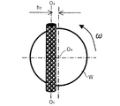
図1及び図2は、ロール状洗浄部材としてロールブラシを用いた、従来の基板洗浄装置の概要を示す。図1及び図2に示すように、この基板洗浄装置には、基板Wの表面(上面)側に位置して、基板Wの表面に接触して該表面にスクラブ洗浄する上部ロールブラシ(ロール状洗浄部材)10と、基板Wの表面に洗浄液を供給する上部洗浄液供給ノズル12が備えられている。また、基板Wの裏面(下面)側に位置して、基板Wの裏面に接触して該裏面にスクラブ洗浄する下部ロールブラシ(ロール状洗浄部材)14と、基板Wの裏面に洗浄液を供給する下部洗浄液供給ノズル16が備えられている。
1 and 2 show an outline of a conventional substrate cleaning apparatus using a roll brush as a roll-shaped cleaning member. As shown in FIG. 1 and FIG. 2, this substrate cleaning apparatus is located on the surface (upper surface) side of the substrate W and is in contact with the surface of the substrate W and scrubs and cleans the surface. A cleaning member) 10 and an upper cleaning
上部ロールブラシ10及び下部ロールブラシ14として、図3に詳細に示すように、外周面に円柱状の多数のノジュール(突起)18aが設けられ、このノジュール18aの突出端面が基板Wの被洗浄面との接触面(接触幅:Li)となるロールブラシ18が用いられている。
As shown in detail in FIG. 3, as the
上部ロールブラシ10は、該ロールブラシ10の軸心を通る線(軸線)O1が基板Wの回転中心を通る線(回転中心線)O2と互いに直交する位置に配置されている。そして、上部洗浄液供給ノズル12から基板Wの表面に洗浄液を供給しながら上部ロールブラシ10を基板Wの表面に所定の圧力で接触させ、同時に、軸線O1を中心に上部ロールブラシ10を、回転中心線O2を中心に基板Wをそれぞれ回転(自転)させることで、基板Wの表面をスクラブ洗浄するように構成されている。
The
同様に、下部ロールブラシ14は、該ロールブラシ14の軸心を通る線(軸線)O3が基板Wの回転中心を通る線(回転中心線)O2と互いに直交する位置に配置されている。そして、下部洗浄液供給ノズル16から基板Wの裏面に洗浄液を供給しながら下部ロールブラシ14を基板Wの裏面に所定の圧力で接触させ、同時に、軸線O3を中心に下部ロールブラシ14を、回転中心線O2を中心に基板Wをそれぞれ回転(自転)させることで、基板Wの裏面をスクラブ洗浄するように構成されている。
Similarly, the
この例の場合、基板Wの表面と裏面は、同一条件で洗浄されるので、以下、上部ロールブラシ10として、図3に示すロールブラシ18を使用して基板Wの表面を洗浄する場合について説明する。
In the case of this example, since the front surface and the back surface of the substrate W are cleaned under the same conditions, the case where the surface of the substrate W is cleaned using the
基板Wの表面の各点をロールブラシ18のノジュール18aが通過する時の単位時間あたりの擦り長さを算出し、基板Wの表面の円周方向に沿った位置(半径r)の平均値を洗浄強度Rc(m/s)とすると、この洗浄強度Rcによって、基板Wの全表面における洗浄均一性を評価できると考えられる。この基板Wの表面の半径rにおける洗浄強度Rcは、下記の式で表される、
The rubbing length per unit time when the
ここに、nは、ロールブラシの円周方向に沿って該ロールブラシに設けられているノジュールの数、Liは、ロールブラシの接触幅(この例の場合、図3に示すように、ノジュール18aの直径)、Rrは、ロールブラシの半径、Vrwは、円周方向に沿ったノジュールの表面と基板の表面との相対速度の平均値であり、下記の式で求められる。
図4に、ロールブラシ18(上部ロールブラシ10)の回転速度を100rpmの一定となし、基板Wの回転速度を、それぞれ50rpm、100rpm及び200rpmと変更して、基板Wの表面をロールブラシ18で洗浄した時における洗浄強度Rcと基板の半径rとの関係を示す。図4から、何れの洗浄条件においても、基板Wの中心近傍領域に洗浄強度Rcの高いピークが見られ、ピークの高さは、洗浄強度Rcの平坦値(洗浄強度Rcがほぼ一定になる値)の6〜30倍になり、洗浄強度Rcのピーク領域の範囲は、基板Wの半径約25mm以内であることが判る。これは、洗浄強度Rcを洗浄強度Rcの平坦値に合わせて基板Wの表面の洗浄を行うと、基板Wの表面の半径約25mm以内の領域に洗浄強度が集中して配線腐食が発生しうることを示唆している。
In FIG. 4, the rotation speed of the roll brush 18 (upper roll brush 10) is made constant at 100 rpm, the rotation speed of the substrate W is changed to 50 rpm, 100 rpm, and 200 rpm, respectively, and the surface of the substrate W is changed with the
また、ロールブラシ18のノジュール18aの直径(接触幅:Li)を3mm、6mm、10mm及び15mmに変化させて洗浄する時の、洗浄強度Rcと基板の半径rとの関係を算出した時の結果を図5に示す。図5から、何れの条件においても、洗浄集中領域が基板の中心部近傍に存在するが、接触幅の減少に従って、洗浄強度Rcのピークの高さとピークの幅は小さくなることが判る。表1に洗浄強度Rcが該洗浄強度Rcの平坦値より20%上昇する時の基板Wの半径位置と接触幅の関係を示す。表1から、実用的な接触幅の範囲(例えば3〜10mm)では、洗浄強度Rcが該洗浄強度Rcの平坦値より20%以上上昇する時の基板Wの半径位置と接触幅との比(r/Li)は、8倍以内程度であることが判る。
Further, when the diameter of the
ロール状洗浄部材によって基板の表面(被洗浄面)を洗浄する時に基板の全表面に亘る洗浄が不均一となるのを緩和するために、ロールブラシやロールスポンジ等のロール状洗浄部材の形状に改良を加えること、例えば、ロールブラシの外周面に、密度や面積がロールブラシの長手方向に沿って異なるように突起(ノジュール)を形成したり(特許文献3参照)、ロールブラシの外径を変化させたりする(特許文献4参照)ことなどが種々提案されている。しかし、何れの提案でも、ロールブラシそのものを、基板との相対位置が変化しないように研磨装置に取り付けているため、ロールブラシや基板の回転条件によって、洗浄強度の被洗浄面上の分布を任意に調整できないと考えられる。 In order to alleviate unevenness of cleaning over the entire surface of the substrate when the surface of the substrate (surface to be cleaned) is cleaned by the roll-shaped cleaning member, the shape of the roll-shaped cleaning member such as a roll brush or roll sponge is reduced. Applying improvements, for example, forming protrusions (nodules) on the outer peripheral surface of the roll brush so that the density and area are different along the longitudinal direction of the roll brush (see Patent Document 3), or reducing the outer diameter of the roll brush. Various changes have been proposed (see Patent Document 4). However, in any proposal, since the roll brush itself is attached to the polishing apparatus so that the relative position with respect to the substrate does not change, the distribution of the cleaning strength on the surface to be cleaned is arbitrary depending on the rotation conditions of the roll brush and the substrate. It is thought that it cannot be adjusted.
基板を該基板の回転(自転)に伴って水平面内でロール状洗浄部材と平行に往復移動させるようにした洗浄装置(引用文献5参照)が提案されている。更に、上部ロールブラシと下部ロールブラシとを、その軸線を基板の回転中心線に対して平行かつ該回転中心線と直交する方向にずらして配置するようにした洗浄装置(引用文献6参照)が提案されている。 There has been proposed a cleaning apparatus (see cited document 5) in which a substrate is reciprocated in parallel with a roll-shaped cleaning member in a horizontal plane as the substrate rotates (rotates). Furthermore, there is a cleaning device (see Reference Document 6) in which the upper roll brush and the lower roll brush are arranged with their axes shifted in a direction parallel to the rotation center line of the substrate and perpendicular to the rotation center line. Proposed.
しかしながら、引用文献1〜6に記載の洗浄装置は、ノジュールとの接触幅及び接触頻度を考慮して、基板の被洗浄面の半径方向に沿った各位置(領域)における洗浄強度を考慮したものではない。このため、たとえ基板の表面(被洗浄面)をロール状洗浄部材と平行に往復移動させながら基板の被洗浄面を洗浄したり、更には、上部ロールブラシと下部ロールブラシとを、その軸線を基板の回転中心線に対して平行かつ該回転中心線と直交する方向にずらして配置したとしても、基板の被洗浄面の全面をより均一な洗浄強度でスクラブ洗浄することは困難であると考えられる。
However, the cleaning apparatuses described in the cited
本発明は上記事情に鑑みてなされたもので、基板の被洗浄面の半径方向に沿った各位置(領域)における洗浄強度を考慮して、基板の全被洗浄面をより均一な洗浄強度でスクラブ洗浄することができるようにした基板洗浄方法及び基板洗浄装置を提供することを目的とする。 The present invention has been made in view of the above circumstances, and in consideration of the cleaning strength at each position (region) along the radial direction of the surface to be cleaned of the substrate, the entire surface to be cleaned of the substrate can be more uniformly cleaned. It is an object of the present invention to provide a substrate cleaning method and a substrate cleaning apparatus that can perform scrub cleaning.
本発明の一参考例は、ロール状洗浄部材の外周面を回転中の基板の被洗浄面に所定の接触幅で接触させて該被洗浄面をスクラブ洗浄する基板洗浄方法であって、前記洗浄部材によるスクラブ洗浄中の全過程の少なくとも一部において、前記洗浄部材の軸線が基板の回転中心線から前記接触幅の0.14〜0.5倍離れたオフセット洗浄位置に該洗浄部材を配置してスクラブ洗浄を行うことを特徴とする基板洗浄方法である。 One reference example of the present invention is a substrate cleaning method for scrub cleaning a surface to be cleaned by bringing the outer peripheral surface of a roll-shaped cleaning member into contact with the surface to be cleaned with a predetermined contact width. In at least a part of the entire process during scrub cleaning by the member, the cleaning member is disposed at an offset cleaning position in which the axis of the cleaning member is 0.14 to 0.5 times the contact width from the rotation center line of the substrate. The substrate cleaning method is characterized by performing scrub cleaning.
このように、スクラブ洗浄中の全過程の少なくとも一部において、オフセット洗浄位置にロール状洗浄部材を配置してスクラブ洗浄を行うことで、基板の被洗浄面の中心部が集中して洗浄されることを緩和し、しかも、オフセット洗浄位置を、洗浄部材の軸線が基板の回転中心線から接触幅の0.14〜0.5倍離れた位置とすることで、基板の被洗浄面の中心部が洗浄されなくなることを防止することができる。 In this way, in at least a part of the entire process during scrub cleaning, the central portion of the surface to be cleaned of the substrate is concentrated and cleaned by disposing the roll cleaning member at the offset cleaning position and performing the scrub cleaning. In addition, the offset cleaning position is set at a position where the axis of the cleaning member is separated from the rotation center line of the substrate by 0.14 to 0.5 times the contact width, so that the center portion of the surface to be cleaned of the substrate is Can be prevented from being washed out.
本発明の一態様は、ロール状洗浄部材の外周面を回転中の基板の被洗浄面に前記洗浄部材の軸線方向に対し直交する方向において所定の接触幅で接触させて該被洗浄面をスクラブ洗浄する基板洗浄方法であって、前記洗浄部材によるスクラブ洗浄中に、前記洗浄部材の軸線と基板の回転中心線とが互いに交わる位置の近傍で、前記洗浄部材を基板の被洗浄面と平行に前記接触幅の16倍以内の移動幅の範囲内で往復移動させることを特徴とする基板洗浄方法である。 In one embodiment of the present invention, the outer peripheral surface of the roll-shaped cleaning member is brought into contact with the surface to be cleaned of the rotating substrate with a predetermined contact width in a direction orthogonal to the axial direction of the cleaning member, and the surface to be cleaned is scrubbed. A substrate cleaning method for cleaning, wherein, during scrub cleaning by the cleaning member, the cleaning member is parallel to the surface to be cleaned in the vicinity of the position where the axis of the cleaning member and the rotation center line of the substrate intersect each other. The substrate cleaning method is characterized in that the substrate is reciprocated within a range of movement width within 16 times the contact width.
このように、洗浄部材の軸線と基板の回転中心線とが互いに交わる位置の近傍で、洗浄部材を基板の被洗浄面と平行に接触幅の16倍以内の移動幅の範囲内で往復移動させてスクラブ洗浄を行うことで、基板の被洗浄面の各領域における洗浄強度が該洗浄強度の平坦値より20%以上上昇することを抑制することができる。 As described above, the cleaning member is reciprocated within a range of movement width within 16 times the contact width in parallel with the surface to be cleaned in the vicinity of the position where the axis of the cleaning member and the rotation center line of the substrate intersect each other. By performing scrub cleaning, it is possible to prevent the cleaning strength in each region of the surface to be cleaned of the substrate from increasing by 20% or more from the flat value of the cleaning strength.
本発明の好ましい態様は、前記洗浄部材の移動速度を、前記洗浄部材の軸線と基板の回転中心線とが互いに交わる位置を該洗浄部材が最も速い速度で通過するように制御することを特徴とする。 In a preferred aspect of the present invention , the moving speed of the cleaning member is controlled so that the cleaning member passes through a position where the axis of the cleaning member and the rotation center line of the substrate intersect each other at the highest speed. you.
これにより、洗浄部材の軸線と基板の回転中心線とが互いに交わる位置及び該位置の近傍を洗浄部材が通過する時間を短くして、基板の被洗浄面を該被洗浄面の全面に亘ってより均一に洗浄することができる。 This shortens the time at which the cleaning member passes through the position where the axis of the cleaning member and the rotation center line of the substrate cross each other and the vicinity of the position so that the surface to be cleaned covers the entire surface to be cleaned. More uniform cleaning is possible.
本発明の好ましい態様は、前記洗浄部材の移動速度を、前記洗浄部材の軸線と基板の回転中心線とが互いに交わる位置から該洗浄部材が離れる距離に反比例し、最大移動速度と最小移動速度の比が3〜11となるように制御することを特徴とする。
これにより、洗浄部材の移動速度に依存して変化する洗浄強度を基板の全被洗浄面に亘ってより均一にすることができる。
In a preferred aspect of the present invention , the moving speed of the cleaning member is inversely proportional to the distance of the cleaning member from the position where the axis of the cleaning member and the rotation center line of the substrate intersect each other, and the maximum moving speed and the minimum moving speed are ratio you and controls so that 3 to 11.
Thereby, the cleaning strength that changes depending on the moving speed of the cleaning member can be made more uniform over the entire surface to be cleaned of the substrate.
本発明の他の態様は、ロール状洗浄部材の外周面を回転中の基板の被洗浄面に接触させて該被洗浄面をスクラブ洗浄する基板洗浄方法であって、前記洗浄部材を複数の洗浄位置にそれぞれ所定時間停滞させてスクラブ洗浄を行い、前記複数の洗浄位置の内の少なくとも1つの洗浄位置は、前記洗浄部材の軸線が基板の回転中心線から離れた位置に前記洗浄部材が位置するオフセット洗浄位置であることを特徴とする基板洗浄方法である。 Another aspect of the present invention is a substrate cleaning method for scrub cleaning a surface to be cleaned by bringing the outer peripheral surface of the roll-shaped cleaning member into contact with the surface to be cleaned of the rotating substrate, wherein the cleaning member is subjected to a plurality of cleaning operations. Scrub cleaning is carried out while stagnating at each position for a predetermined time, and at least one of the plurality of cleaning positions is such that the cleaning member is positioned at a position where the axis of the cleaning member is away from the rotation center line of the substrate. A substrate cleaning method characterized by being at an offset cleaning position.
このように、洗浄部材の軸線が基板の回転中心線から離れたオフセット洗浄位置に洗浄部材を位置させて洗浄することで、基板の中心部に洗浄強度が集中することを緩和することができる。 As described above, the cleaning member is positioned at the offset cleaning position where the axis of the cleaning member is distant from the rotation center line of the substrate, and thus the concentration of the cleaning strength at the center of the substrate can be mitigated.
本発明の好ましい態様は、前記オフセット洗浄位置を複数有し、前記洗浄部材が前記各オフセット洗浄位置に停滞する滞在時間が各オフセット洗浄位置と基板の回転中心線との距離に比例することを特徴とする。
これにより、基板の被洗浄面を該被洗浄面の全面に亘ってより均一に洗浄することができる。
In a preferred aspect of the present invention , there are a plurality of the offset cleaning positions, and the staying time during which the cleaning member stays at each offset cleaning position is proportional to the distance between each offset cleaning position and the rotation center line of the substrate. It shall be the.
Thereby, the surface to be cleaned of the substrate can be more uniformly cleaned over the entire surface to be cleaned.
本発明の好ましい態様は、前記洗浄部材の外周面には、基板の被洗浄面に接触する複数のノジュールが、前記洗浄部材の中心部から外方に向かうに従って、分布が密となるように配置されていることを特徴とする。
これによって、基板の中心部に洗浄強度が集中することを、洗浄部材自体によって緩和することができる。
In a preferred aspect of the present invention , a plurality of nodules that contact the surface to be cleaned of the cleaning member are arranged on the outer peripheral surface of the cleaning member so that the distribution becomes denser toward the outside from the center of the cleaning member. it characterized in that it is.
As a result, the concentration of the cleaning strength at the center of the substrate can be mitigated by the cleaning member itself.
本発明の他の態様は、ロール状洗浄部材の外周面を回転中の基板の被洗浄面に前記洗浄部材の軸線方向に対し直交する方向において所定の接触幅で接触させてスクラブ洗浄する洗浄装置であって、前記洗浄部材の軸線が基板の回転中心線から前記接触幅の0.14〜0.5倍離れたオフセット洗浄位置に該洗浄部材を移動させストッパを介して停止させる移動機構と、前記ストッパの位置を調整するストッパ位置調整部を有することを特徴とする基板洗浄装置である。 Another aspect of the present invention is a cleaning apparatus for scrub cleaning by bringing an outer peripheral surface of a roll-shaped cleaning member into contact with a surface to be cleaned of a rotating substrate with a predetermined contact width in a direction orthogonal to the axial direction of the cleaning member. A moving mechanism for moving the cleaning member to an offset cleaning position in which the axis of the cleaning member is separated from the rotation center line of the substrate by 0.14 to 0.5 times the contact width, and stopping it through a stopper; The substrate cleaning apparatus includes a stopper position adjusting unit that adjusts the position of the stopper.
これにより、洗浄部材の停止位置をストッパによって機械的に規制することで再現性を良くし、しかもストッパ位置調整部によって、ストッパの位置を容易かつ迅速に調整することができる。 As a result, the stop position of the cleaning member is mechanically restricted by the stopper to improve reproducibility, and the stopper position adjustment unit can easily and quickly adjust the position of the stopper.
本発明の他の態様は、ロール状洗浄部材の外周面を回転中の基板の被洗浄面に前記洗浄部材の軸線方向に対し直交する方向において所定の接触幅で接触させてスクラブ洗浄する洗浄装置であって、前記洗浄部材の軸線と基板の回転中心線とが互いに交わる位置の近傍で、前記洗浄部材を基板の被洗浄面と平行に前記接触幅の16倍以内の移動幅の範囲内で往復移動させる往復移動機構を有することを特徴とする基板洗浄装置である。 Another aspect of the present invention is a cleaning apparatus for scrub cleaning by bringing an outer peripheral surface of a roll-shaped cleaning member into contact with a surface to be cleaned of a rotating substrate with a predetermined contact width in a direction orthogonal to the axial direction of the cleaning member. In the vicinity of the position where the axis of the cleaning member and the rotation center line of the substrate cross each other, the cleaning member is parallel to the surface to be cleaned within the range of movement width within 16 times the contact width. A substrate cleaning apparatus having a reciprocating mechanism for reciprocating movement.
本発明の好ましい態様は、前記往復移動機構は、前記洗浄部材の移動速度を制御する制御部を有することを特徴とする。 A preferred embodiment of the present invention, the reciprocating mechanism, characterized by having a control unit for controlling the moving speed of the cleaning member.
本発明の好ましい態様は、前記往復移動機構は、枢軸を介して一端を回転自在に支承した前記洗浄部材を、該枢軸を中心に揺動させるように構成されていることを特徴とする。 A preferred embodiment of the present invention, the reciprocating mechanism, the cleaning member which is rotatably supported at one end via a pivot, characterized in that it is configured to swing around a該枢axis.
これにより、洗浄部材の基端のみに駆動機構を設けて、構造の簡単化を図ることができる。しかも、洗浄強度が基板の被洗浄面の中心部で弱く、外周部で弱くなるように、洗浄部材の自由端側の押付け圧力を調整することができる。 Thereby, a drive mechanism can be provided only at the base end of the cleaning member, and the structure can be simplified. In addition, the pressing pressure on the free end side of the cleaning member can be adjusted so that the cleaning strength is weak at the center of the surface to be cleaned of the substrate and weak at the outer periphery.
本発明の他の態様は、ロール状洗浄部材の外周面を回転中の基板の被洗浄面に接触させて該被洗浄面をスクラブ洗浄する基板洗浄装置であって、前記洗浄部材を、前記洗浄部材の軸線が基板の回転中心線と互いに交わる位置に該洗浄部材が位置する洗浄位置と、前記洗浄部材の軸線が基板の回転中心線から離れた位置に該洗浄部材が位置する、少なくとも1つのオフセット洗浄位置との間を往復移動させて各洗浄位置に所定時間停滞させる往復移動機構を有することを特徴とする基板洗浄装置である。 Another aspect of the present invention is a substrate cleaning apparatus for scrub cleaning the surface to be cleaned by bringing the outer peripheral surface of the roll-shaped cleaning member into contact with the surface to be cleaned of the rotating substrate, wherein the cleaning member At least one cleaning position in which the cleaning member is located at a position where the axis of the member intersects with the rotation center line of the substrate; and at least one cleaning member is located at a position where the axis of the cleaning member is away from the rotation center line of the substrate A substrate cleaning apparatus having a reciprocating mechanism for reciprocating between an offset cleaning position and stagnating at each cleaning position for a predetermined time.
本発明の好ましい態様は、前記往復移動機構は、前記洗浄部材を前記各洗浄位置に位置決めして停止させる、位置調整可能なストッパを有することを特徴とする。
これにより、洗浄部材の停止位置をストッパによって機械的に規制することで再現性を良くし、しかもストッパの位置を容易かつ迅速に調整することができる。
A preferred embodiment of the present invention, the reciprocating mechanism, the cleaning member is positioned in each of the cleaning position is stopped, it characterized as having a position adjustable stop.
Thereby, reproducibility is improved by mechanically restricting the stop position of the cleaning member with the stopper, and the position of the stopper can be adjusted easily and quickly.
本発明の好ましい態様は、前記オフセット洗浄位置は複数設けられ、各オフセット洗浄位置に前記洗浄部材が停滞する滞在時間を、各オフセット洗浄位置と基板の回転中心線との距離に比例するように制御することを特徴とする。 In a preferred aspect of the present invention, a plurality of the offset cleaning positions are provided, and a staying time during which the cleaning member stays at each offset cleaning position is controlled to be proportional to a distance between each offset cleaning position and the rotation center line of the substrate. it shall be the feature of the that.
本発明の好ましい態様は、前記洗浄部材の外周面には、基板の被洗浄面に接触する複数のノジュールが、前記洗浄部材の中心部から外方に向かうに従って、分布が密となるように配置されていることを特徴とする。 In a preferred aspect of the present invention , a plurality of nodules that contact the surface to be cleaned of the cleaning member are arranged on the outer peripheral surface of the cleaning member so that the distribution becomes denser toward the outside from the center of the cleaning member. it characterized in that it is.
本発明によれば、ロール状洗浄部材と基板の被接触面との接触密度を調整して洗浄強度を該被接触面の全面に亘って均等化させ、これによって、基板の中心部近傍に洗浄強度が集中して局部配線の腐食や表面荒れ等が生じることを防止しつつ、洗浄効率を向上させることができる。 According to the present invention, the contact strength between the roll-shaped cleaning member and the contacted surface of the substrate is adjusted to equalize the cleaning strength over the entire surface of the contacted surface, thereby cleaning near the center of the substrate. Cleaning efficiency can be improved while preventing corrosion of the local wiring and surface roughness from occurring due to concentration of strength.
以下、本発明の実施形態を図面を参照して説明する。なお、以下の各例では、ロール状洗浄部材として、図3に示す、外周面に多数のノジュール(突起)18aを設けて該ノジュール18aの突出端面を基板Wの被洗浄面と接触面(接触幅:Li)としたロールブラシ18を使用している。また、同一または相当する部材には、同一符号を付して重複した説明を省略する。
Hereinafter, embodiments of the present invention will be described with reference to the drawings. In each of the following examples, as the roll-shaped cleaning member, a large number of nodules (projections) 18a are provided on the outer peripheral surface shown in FIG. 3, and the protruding end surface of the
図6乃至図9は、本発明の実施形態の基板洗浄装置20aを示す。この基板洗浄装置20aは、半導体ウェーハ等の基板Wの周縁部を挟持して該基板Wを水平に保持する複数(図示では計4個)の回転ローラ22を備えており、回転ローラ22で水平に保持された基板Wは、回転ローラ22の回転(自転)に伴って、基板Wの中心を回転中心として該回転中心を通る線(回転中心線)O4を中心に回転するようになっている。
6 to 9 show a
回転ローラ22で保持された基板Wの表面(上面)側に位置して、基板Wの表面に接触して該表面をスクラブ洗浄する上部ロールブラシ(ロール状洗浄部材)24と、基板Wの表面に洗浄液を供給する上部洗浄液供給ノズル26が備えられている。この上部ロールブラシ24として、図3に示す、外周面に多数の円柱状のノジュール(突起)18aを設けたロールブラシ18(接触幅:Li)が使用されている。上部ロールブラシ24の回転軸28は、上部ロールブラシ24の軸心を通る線(軸線)O5を中心に上部ロールブラシ24を回転(自転)させる駆動モータ30に連結されている。
An upper roll brush (roll-like cleaning member) 24 that is positioned on the surface (upper surface) side of the substrate W held by the rotating
回転ローラ22で保持された基板Wの側方に位置して、移動機構としての走行用シリンダ32と、この走行用シリンダ32の作動に伴って走行ガイド34をガイドとして上部ロールブラシ24の軸心O5と水平面内で直交する方向に走行する走行体36が配置され、この走行体36の上面に昇降用シリンダ38が垂直に立設されている。そして、この昇降用シリンダ38の上方に延びるシリンダロッドの上端に上記駆動モータ30が連結されている。更に、走行ガイド34の走行方向に沿った所定位置には、走行体36の端面に当接して該走行体36の走行を停止させ、これによって、上部ロールブラシ24の回転ローラ22で保持された基板Wの該基板Wの回転中心線O4と水平面で直交する方向の位置決めを行うストッパ40が配置されている。このストッパ40は、この例では、ボルト42の頭部で構成され、ボルト42の締め付け量を調整することで、ストッパ40の位置決めを行うようになっている。これにより、ボルト42によって、ストッパ40の位置を調整するストッパ位置調整部が構成されている。
Located on the side of the substrate W held by the rotating
ストッパ40は、上部ロールブラシ24の軸心O5が基板Wの回転中心線O4から上記接触幅Li(図3参照)の0.14〜0.5倍離れたオフセット洗浄位置に上部ロールブラシ24を停止させる位置に配置される。つまり、上部ロールブラシ24の軸心O5が基板Wの回転中心線O4からのオフセット量Δは、上記接触幅Li(図3参照)の0.14〜0.5倍(Δ=0.14〜0.5Li)に設定されている。そして、ストッパ40の位置は、ボルト(ストッパ位置調整部)42によって、容易に調整される。
The
回転ローラ22で保持された基板Wの裏面(下面)側に位置して、基板Wの裏面に接触して該裏面をスクラブ洗浄する下部ロールブラシ(ロール状洗浄部材)50と、基板Wの裏面に洗浄液を供給する下部洗浄液供給ノズル52が備えられている。この下部ロールブラシ50として、図3に示す、外周面に多数の円柱状のノジュール(突起)18aを設けたロールブラシ18が使用されている。
A lower roll brush (roll cleaning member) 50 that is located on the back surface (lower surface) side of the substrate W held by the rotating
下部ロールブラシ50の回転軸54は従動プーリ56が、下部ロールブラシ50の下方に配置された駆動モータ58には駆動プーリ60はそれぞれ固定され、両プーリ56,60間には、ベルト62が掛け渡されている。これによって、駆動モータ58の駆動に伴って、下部ロールブラシ50は、その軸心を通る線(軸線)O6を中心に回転(自転)するようになっている。更に、駆動モータ58の下方に位置して、該駆動モータ58及び下部ロールブラシ50を一体に昇降させる昇降用シリンダ64が配置されている。
The
この例では、前述の上部ロールブラシ24と同様に、下部ロールブラシ50の軸心O6が基板Wの回転中心線O4からオフセット量Δ(Δ=0.14〜0.5Li)だけ離れたオフセット洗浄位置に下部ロールブラシ50が位置してスクラブ洗浄を行うようになっている。
In this example, similarly to the
なお、この例では、下部ロールブラシ50の軸心O6が基板Wの回転中心線O4からオフセット量Δ(Δ=0.14〜0.5Li)だけ離れたオフセット洗浄位置に下部ロールブラシ50が位置してスクラブ洗浄を行うようになっているが、例えば基板Wの裏面の洗浄度がそれ程要求されない場合には、下部ロールブラシ50の軸心O6が基板Wの回転中心線O4と交わる位置に下部ロールブラシ50が位置するようにしてもよい。更に、前述の上部ロールブラシ24と同様に、下部ロールブラシ50を基板Wの回転中心線O4と平面上で直交する方向に移動自在に構成し、ストッパ等を介して、下部ロールブラシ50の位置決めを行って、所定のスクラブ洗浄位置に停止させるように構成しても良い。
In this example, the
この例に基板洗浄装置20aよれば、まず回転ローラ22で基板Wを水平に保持する。一方、上部ロールブラシ24にあっては、走行用シリンダ32を作動して走行体36を走行させ該走行体36をストッパ40に当接させることで、上部ロールブラシ24の位置決めを行う。そして、回転ローラ22を回転(自転)させることで、基板Wをその中心の回転中心軸O4を中心に、例えば100rpm程度の回転速度で回転(自転)させる。
According to the
この状態で、基板Wの表面にあっては、上部洗浄液供給ノズル26から基板Wの表面(上面)に洗浄液を供給し、同時に、上部ロールブラシ24を、その軸心O5を中心に回転させながら下降させて基板Wの表面に接触させ、これによって、該表面の上部ロールブラシ24によるスクラブ洗浄を行う。このスクラブ洗浄時、上部ロールブラシ24は、図3に示すように、上部ロールブラシ24として使用されるロールブラシ18に設けられているノジュール18aの上端面において、接触幅Liで基板Wの表面と接触する。
In this state, in the surface of the substrate W, the cleaning liquid is supplied from the upper cleaning
基板Wの裏面にあってもほぼ同様に、下部洗浄液供給ノズル52から基板Wの裏面(下面)に洗浄液を供給し、同時に、下部ロールブラシ50を、その軸心O6を中心に回転させながら上昇させて基板Wの裏面に接触させ、これによって、該裏面の下部ロールブラシ50によるスクラブ洗浄を行う。
Substantially the same manner even in the back surface of the substrate W, the cleaning liquid is supplied from the lower cleaning
そして、スクラブ洗浄が終了した後、上部ロールブラシ24を上昇させ、下部ロールブラシ50を下降させた後、上部洗浄液供給ノズル26及び下部洗浄液供給ノズル52からの洗浄液の供給を停止し、更に回転ローラ22、上部ロールブラシ24及び下部ロールブラシ50の回転を停止させる。
After the scrub cleaning is completed, the
ここに、上部ロールブラシ24の軸線O5、更には下部ロールブラシ50の軸線O6の基板Wの回転中心線O4からのオフセット量Δを接触幅(この例では、ノジュール18aの直径)Liの0.14〜0.5倍に設定している。これは、以下の理由による。
Here, the offset amount Δ of the axis O 5 of the
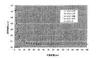
つまり、図10に示すように、上部ロールブラシ24の軸線O5の基板Wの回転中心線O4からのオフセット量h1と接触幅(ノジュールの直径)Li(図3参照)との比(h1/Li)を0,0.27,0.68,1.37及び2.74に変化させて上部ロールブラシ24で基板Wの表面の洗浄する時における前記洗浄強度Rcと基板Wの半径rとの関係を算出した結果を図11に示す。また、オフセット量h1と接触幅Liとの比(h1/Li)を、0,0.14,0.27,0.41,0.50,0.55,0.68,1.37,2.74,4.11,4.79及び5.48に変化させて上部ロールブラシ24で基板Wの表面の洗浄した時における前記洗浄強度Rcの標準偏差の相対値(均一性)1σを算出した結果を表2に示す。
That is, as shown in FIG. 10, the ratio between the offset amount h 1 of the axis O 5 of the
図11から、オフセット量h1と接触幅Liの比(h1/Li)が0.5以下(h1/Li<0.5)の場合、基板の中心部の洗浄強度が集中する範囲は狭くなり、均一性1σは小さくなり、オフセット量hと接触幅Liの比(h1/Li)を0.5以上(h1/Li>0.5)にすると、基板の中心部の洗浄強度が集中する特異点がなくなり、均一性1σは更に小さくなるが、基板の中心部に洗浄が出来ない領域が現れることが判る。また、表2から、オフセット量h1と接触幅Liの比(h1/Li)を0.14以上(h1/Li>0.14)とすることで、均一性1σに対する効果が現れることが判る。従って、ロールブラシの位置を固定して洗浄する場合、オフセット量h1と接触幅Liの比(h1/Li)は、0.14以上0.50以下であることが望ましい。 From FIG. 11, when the ratio (h 1 / Li) between the offset amount h 1 and the contact width Li is 0.5 or less (h 1 /Li<0.5), the range in which the cleaning strength at the center of the substrate is concentrated is When the ratio 1 becomes smaller and the uniformity 1σ becomes smaller and the ratio of the offset amount h to the contact width Li (h 1 / Li) is 0.5 or more (h 1 /Li>0.5), the cleaning strength at the center of the substrate is reduced. It can be seen that there is no singularity where the concentration is concentrated, and the uniformity 1σ is further reduced, but an area that cannot be cleaned appears in the center of the substrate. Also, from Table 2, the effect on the uniformity 1σ appears when the ratio of the offset amount h 1 to the contact width Li (h 1 / Li) is 0.14 or more (h 1 /Li>0.14). I understand. Accordingly, when cleaning is performed with the position of the roll brush fixed, the ratio (h 1 / Li) between the offset amount h 1 and the contact width Li is preferably 0.14 or more and 0.50 or less.
図12乃至図14は、本発明の他の実施形態に係る基板洗浄装置20bを示す。この基板洗浄装置20bは、正逆回転及び回転速度が制御可能な走行用モータ70と、この走行用モータ70の出力軸と走行体36とを結ぶボールねじ等の直動機構72と、走行用モータ70を制御する制御部74によって構成されて、回転ローラ22で保持した基板Wの回転中心線O4と水平面内で直交する方向に走行体36を上部ロールブラシ24と共に往復移動させる往復移動機構76を備えている。これによって、走行用モータ70の正転に伴って、走行体36は、上部ロールブラシ24と共に、例えば図12の右方向に移動し、走行用モータ70の逆転に伴って、走行体36は、上部ロールブラシ24と共に、例えば図12の左方向に移動する。走行体36の移動速度、停止位置及び停滞(停止)時間は、制御部74で走行用モータ70の回転速度及び回転方向を制御することで制御される。
12 to 14 show a
この例では、上部ロールブラシ24の軸心O5が基板Wの回転中心線O4と交差する洗浄位置と、上部ロールブラシ24の軸心O5が基板Wの回転中心線O4からオフセット量Δだけオフセットしたオフセット洗浄位置の少なくとも2つの洗浄位置の間を上部ロールブラシ24が往復移動するように、往復移動機構76を介して、走行体36が往復移動する。
In this example, a cleaning position in which the axis O 5 of the
次に、この基板洗浄装置20bによる基板Wの表面の洗浄処理について説明する。
先ず、第1の洗浄処理では、図15に示す、上部ロールブラシ24の軸心O5と基板Wの回転中心線O4とのオフセット量h2が0mmの第1洗浄位置(中央洗浄位置)、オフセット量h2が、例えば10mmの第1オフセット洗浄位置、及びオフセット量h2が、例えば20mmの第2オフセット洗浄位置の3つの洗浄位置に上部ロールブラシ24を位置させて基板Wの表面を洗浄する。つまり、上部ロールブラシ24を第1洗浄位置(中央洗浄位置)に位置させて所定時間基板Wの表面を洗浄した後、上部ロールブラシ24を第1オフセット洗浄位置に位置させて所定時間基板Wの表面を洗浄し、しかる後、上部ロールブラシ24を第2オフセット洗浄位置に位置させて所定時間基板Wの表面を洗浄する。そして、上部ロールブラシ24を第1オフセット洗浄位置に位置させて所定時間基板Wの表面を洗浄し、しかる後、上部ロールブラシ24を第1洗浄位置(中央洗浄位置)に位置させて所定時間基板Wの表面を洗浄する。以降、この洗浄処理を繰り返す。
Next, the cleaning process of the surface of the substrate W by the
First, in the first cleaning process, a first cleaning position (center cleaning position) in which the offset amount h 2 between the axis O 5 of the
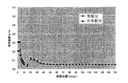
ここに、それぞれの洗浄位置に上部ロールブラシ24を等時間停滞させて基板Wの表面を洗浄する場合(等配分)、つまり第1洗浄位置(中央洗浄位置)での上部ロールブラシ24の洗浄時間(停滞時間):t1、第1オフセット洗浄位置での上部ロールブラシ24の洗浄時間(停滞時間):t2、及び第2オフセット洗浄位置での上部ロールブラシ24の洗浄時間(停滞時間):t3を全て等しくした場合(t1=t2=t3)と、それぞれの洗浄位置に上部ロールブラシ24を停滞させる時間を変化させて基板Wの表面を洗浄する場合(分布配分)、つまり第1洗浄位置での上部ロールブラシ24の洗浄時間(停滞時間):t1、第1オフセット洗浄位置での上部ロールブラシ24の洗浄時間(停滞時間):t2、及び第2オフセット洗浄位置での上部ロールブラシ24の洗浄時間(停滞時間):t3を、オフセット量h2に応じて、1:2:3の割合で変化させた場合(t1:t2:t3=1:2:3)の上記洗浄強度Rcと基板Wの半径rとの関係を算出した結果を図16に示す。また、この時の洗浄強度Rcの標準偏差の相対値(均一性)1σを算出した結果を表3に示す。
Here, when the
この図16及び表3から、いずれの場合も、基板の中心部に洗浄強度が集中することを大幅に抑制できることが判る。特に、上部ロールブラシ24の洗浄時間(停滞時間)を均一に配分した場合(等配分)に比べ、上部ロールブラシ24の洗浄時間(停滞時間)を、オフセット量h2に応じて変化させて配分した場合(分布配分)の方が、基板Wの表面(被洗浄面)の全面に亘る均一な洗浄強度が得られ、洗浄強度均一性1σを等配分の65%から分布配分の35%に向上できることが判る。上部ロールブラシ24を各洗浄位置に移動させる際、調整の時間を省くために、上部ロールブラシ24を基板Wの表面から離すことなく移動させることが好ましい。
From FIG. 16 and Table 3, it can be seen that in any case, the concentration of the cleaning strength at the center of the substrate can be significantly suppressed. In particular, when evenly distributed cleaning time (dwell time) of the
第2の洗浄処理では、図15に示す、上部ロールブラシ24の軸心O5と基板Wの回転中心線O4とのオフセット量h2が0mmの第1洗浄位置(中央洗浄位置)と、オフセット量h2が、例えば20mmの第2オフセット洗浄位置の2つの洗浄位置に上部ロールブラシ24を位置させて基板Wの表面を洗浄する。
In the second cleaning process, as shown in FIG. 15, the first cleaning position (center cleaning position) where the offset amount h 2 between the axis O 5 of the
ここに、それぞれの洗浄位置に上部ロールブラシ21の等時間に停止させて基板Wの表面を洗浄する場合(等分布)、つまり第1洗浄位置での上部ロールブラシ24の洗浄時間(停滞時間):t1と第2オフセット洗浄位置での上部ロールブラシ24の洗浄時間(停滞時間):t3とを等しくした場合(t1=t3)と、それぞれの洗浄位置に上部ロールブラシ24を停滞させる時間を変化させて基板Wの表面を洗浄する場合(分布配分)、つまり第1洗浄位置での上部ロールブラシ24の洗浄時間(停滞時間):t1と第2オフセット洗浄位置での上部ロールブラシ24の洗浄時間(停滞時間):t3とを、オフセット量h2に応じて、1:2に変化(比例)させた場合(t1:t3=1:2)の上記洗浄強度Rcと基板Wの半径rとの関係を算出した結果を図17に示す。また、この時の洗浄強度Rcの標準偏差の相対値(均一性)1σを算出した結果を表4に示す。
Here, when the upper roll brush 21 is stopped at each cleaning position at the same time to clean the surface of the substrate W (equal distribution), that is, the cleaning time of the
このように、洗浄位置を2つすると、洗浄強度の被洗浄面の全面に亘る均一性の面では洗浄位置を3つとして場合に及ばないものの、オフセット洗浄位置の数が少ないため、構造的に簡素化することができる。 In this way, when there are two cleaning positions, the number of offset cleaning positions is small, but the number of offset cleaning positions is structurally small in terms of uniformity over the entire surface to be cleaned. It can be simplified.
第3の洗浄処理では、図18に示すように、保持ローラ20で保持した基板Wの回転中心線O4を中心として、この左右に等間隔な移動幅pの範囲内で上部ロールブラシ24を連続して往復移動させて基板Wの表面を洗浄する。この上部ロールブラシ24の移動範囲pは、上記図3に示す接触幅Liの16倍以内(p<16Li)に設定されている。
In the third cleaning process, as shown in FIG. 18, the
これは、前述の表1に示すように、上部ロールブラシ10の軸心O1が基板Wの回転中心線O2と交差する位置に上部ロールブラシ10を配置し、この上部ロールブラシ10として使用されるロールブラシ18のノジュール18aの直径(接触幅:Li)を3mm、6mm、10mm及び15mmに変化させて基板の表面を洗浄した時、実用的な接触幅(ノジュール18aの直径)の範囲(例えば3〜10mm)では、洗浄強度Rcが洗浄強度Rcの平坦値より20%以上上昇する時の基板Wの半径位置と接触幅の比は8倍以内程度であることに基づく。つまり、移動幅pを接触幅Liの16倍以内に設定することで、洗浄強度Rcが洗浄強度Rcの平坦値より20%以上上昇することを抑制することができる。
As shown in Table 1 above, the
この例では、移動幅pは、例えば40mm(p=40mm)に設定されており、上部ロールブラシ24の移動中に上部ロールブラシ24が基板表面の各位置に接触する時間を変化させるために、上部ロールブラシ24の移動速度を、基板の回転中心を通過するときが最も速く、基板の回転中心から離れるに従って順次遅くするように調整している。つまり、上部ロールブラシ24の移動速度の速度係数V(無次元)は、下記の式で表わされる。
In this example, the movement width p is set to 40 mm (p = 40 mm), for example, and in order to change the time during which the
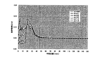
ここで、移動係数の常数Vcを、0.05,0.1,0.3,0.5,1.0及び1.5と変化させて基板Wの表面を洗浄する時の洗浄強度Rcを算出した時の該洗浄強度Rcと基板Wの半径との関係を図19に、基板Wの回転中心から上部ロールブラシ24までの距離(オフセット量)と速度係数比(λ=Vmax/Vc)との関係を図20にそれぞれ示す。
Here, the cleaning strength R when the surface of the substrate W is cleaned by changing the constant V c of the transfer coefficient to 0.05, 0.1, 0.3, 0.5, 1.0, and 1.5. FIG. 19 shows the relationship between the cleaning strength R c and the radius of the substrate W when c is calculated. The distance (offset amount) from the rotation center of the substrate W to the
図20から、x(オフセット量)=0の時の最大速度係数Vmaxと最小速度係数Vcの比λ(=Vmax/Vc)は、それぞれ20.4,10.8,4.3,3.0,2.0,1.7であることが判る。この最大速度係数比(λ=Vmax/Vc)における洗浄強度Rcの標準偏差の相対値(均一性)1σを算出した結果を表5に示す From FIG. 20, the ratio λ (= V max / V c ) between the maximum speed coefficient V max and the minimum speed coefficient V c when x (offset amount) = 0 is 20.4, 10.8, and 4.3, respectively. , 3.0, 2.0, 1.7. Table 5 shows the result of calculating the relative value (uniformity) 1σ of the standard deviation of the cleaning strength R c at this maximum speed coefficient ratio (λ = V max / V c ).
この表5から、いずれの場合も、基板の中心部に洗浄強度が集中することを大幅に抑制することができ、特に、最大移動速度と最小移動速度の比(最大速度係数比:λ)を2〜11、好ましくは、3〜11とすることで、標準偏差の相対値(均一性)1σを40%以下に抑制することができ、速度係数の常数Vcが0.3の時の標準偏差の相対値(均一性)1σは最も小さく、29%となることが判る。 From Table 5, in any case, it is possible to greatly suppress the concentration of the cleaning strength at the center of the substrate. In particular, the ratio of the maximum movement speed to the minimum movement speed (maximum speed coefficient ratio: λ) is 2 to 11, preferably, by a 3 to 11, the relative value of the standard deviation (uniformity) 1 [sigma can be suppressed to 40% or less, constant V c of the speed coefficient when the 0.3 standard It can be seen that the relative value (uniformity) 1σ of the deviation is the smallest, 29%.
以上のVは速度係数であり、実際に洗浄している時の移動速度U1(移動幅pを1回通過する場合)を以下に求める。ここで、上部ロールブラシ24の移動速度U0=V×1(m/s)とすれば、上部ロールブラシ24が移動幅pを通過する時間τは下記の式で求められる。
The above V is a speed coefficient, and the moving speed U 1 (when the moving width p is passed once) during actual cleaning is obtained below. Here, if the moving speed U 0 of the
実際のプロセス処理時間(移動幅pを1回通過する時間)をtとすると、
U1=τ×U0/t
になる。
Assuming that the actual process processing time (time for passing the movement width p once) is t,
U 1 = τ × U 0 / t
become.
以上の移動速度U1は、移動幅pを1回通過する場合の値(時間)である。プロセスに応じて同じ処理時間で移動幅をM回が必要とする場合、上部ロールブラシ24の移動速度Uは、M×U1(U=M×U1)となる。
Or the moving speed U 1 of a value in the case of one pass through the movement width p (time). When the movement width needs M times in the same processing time according to the process, the moving speed U of the
図21乃至図22は、本発明の更に他の実施形態の基板洗浄装置20cを示す。この基板洗浄装置20cの前記基板洗浄装置20bと異なる点は、走行体36を走行させる第1走行用シリンダ80と、第1走行用シリンダ80を走行体36と共に走行させる第2走行用シリンダ82によって、往復移動機構84を構成している点にある。走行体36は、走行ガイド86にガイドされて走行するように構成され、この走行ガイド86に沿った位置には、走行体36の端面に当接して該走行体36の移動を停止させる一対のストッパ88a,88bが配置されている。更に、第1走行用シリンダ80は、走行ガイド90にガイドされて走行するように構成され、この走行ガイド90に沿った位置には、第1走行用シリンダ80の端面に当接して該第1走行用シリンダ80の移動を停止させる一対のストッパ92a,92bが配置されている。これらの各ストッパ88a,88b,92a,92bは、ボルトで構成され、該ボルトの締め付け量を調整することで、走行体36及び第1走行用シリンダ80の左右の停止位置を調整できるようになっている。
21 to 22 show a
そして、この例では、走行体36を一方のストッパ88aに当接する位置から他方のストッパ88bに当接する位置まで走行させることで、上部ロールブラシ24を第1オフセット洗浄位置(位置B)から中央洗浄位置(位置A)に移動させ、第1走行用シリンダ80を走行体36と共に一方のストッパ92aに当接する位置から他方のストッパ92bに当接する位置まで走行させることで、上部ロールブラシ24を第2オフセット洗浄位置(位置C)から第1オフセット洗浄位置(位置B)に移動させて、基板Wの表面をスクラブ洗浄するように構成されている。
In this example, the
このように、上部ロールブラシ24の停止位置(洗浄位置)をストッパ88a,88b,92a,92bによって機械的に規制することで再現性を良くし、しかもストッパ88a,88b,92a,92bを、例えばボルト等で構成することで、ストッパ88a,88b,92a,92bの位置を容易かつ迅速に調整することができる。
As described above, the stop position (cleaning position) of the
なお、上記各例においては、移動の前後に互いに平行となるように上部ロールブラシ24を横移動させるようにしているが、図23に示すように、上部ロールブラシ24の一端を枢軸94を介して揺動自在に支承し、この枢軸94を中心に上部ロールブラシ24を基板Wと平行に水平方向に揺動させるようにしてもよい。このように、上部ロールブラシ24を枢軸94を中心に揺動させても、上部ロールブラシ24を横移動させるようにした場合と同様な効果が得られ、例えば基板Wとして300mmの半導体ウェーハを使用した場合、上部ロールブラシ24の片側揺動角度を約10°とすることで、図10に示すオフセット量h1を20mmとした場合とほぼ同等な効果を得ることができる。しかも、上部ロールブラシ24の一端(基端)のみに駆動機構を設けることで、構造の簡単化を図ることができる。
In each of the above examples, the
また、図24に示すように、上部ロールブラシ24の自由端側に可変荷重Wfを加える機構を設けることで、上部ロールブラシ24の長手方向に沿って傾斜した押付け圧を形成し、基板Wの中心部より外周部の方が高い押付け圧とすることで、基板Wの上面に対するより均一な洗浄強度を得ることができる。
Also, as shown in FIG. 24, by providing a mechanism for applying a variable load Wf to the free end side of the
図25は、本発明の実施形態の基板洗浄装置20aを備えた研磨装置を示す。図25に示すように、この研磨装置は、基板を搬入・搬出するロード・アンロード部100、基板表面を研磨して平坦化する研磨部102、研磨後の基板を洗浄する洗浄部104及び基板を搬送する基板搬送部106を備えている。ロード・アンロード部100は、半導体ウェーハ等の基板をストックする複数(図示では3個)の基板カセットを載置するフロントロード部108と、第1搬送ロボット110を備えている。
FIG. 25 shows a polishing apparatus provided with the
研磨部102には、この例では、4つの研磨ユニット112が備えられ、基板搬送部106は、互いに隣接した2つの研磨ユニット間で基板の搬送を行う第1リニアトランスポータ114a及び第2リニアトランスポータ114bから構成されている。洗浄部104は、粗洗浄を行う、本発明の実施形態に係る2つの基板洗浄装置20a、スピンドライ方式を採用して仕上げ洗浄を行う仕上げ洗浄装置118及び乾燥ユニット120を有している。更に、第1リニアトランスポータ114a、第2リニアトランスポータ114b及び洗浄部104の間に位置して第2搬送ロボット122が配置されている。
In this example, the polishing
なお、この例では、図6乃至図9に示す基板洗浄装置20aを使用して研磨後の基板を洗浄するようにしているが、この基板洗浄装置20aの代わりに、図12乃至図14に示す基板洗浄装置20b、または図21及び図22に示す基板洗浄装置20cを使用してもよい。
In this example, the polished substrate is cleaned using the
この研磨装置にあっては、フロントロード部108に搭載された基板カセットから第1搬送ロボット110で取り出された基板は、第1リニアトランスポータ114a、または第1リニアトランスポータ114a及び第2リニアトランスポータ114bを介して、研磨部102の少なくとも1つの研磨ユニット112に搬送される。そして、研磨ユニット112で研磨された基板は、第2搬送ロボット122で洗浄部104に搬送され、洗浄部104の基板洗浄装置20a及び仕上げ洗浄装置118で順次洗浄され、乾燥ユニット120で乾燥された後、第1搬送ロボット110でフロントロード部108に搭載された基板カセットに戻される。
In this polishing apparatus, the substrate taken out by the
上記各実施形態おいては、ロール状洗浄材(上部ロールブラシ24及び下部ロールブラシ50)として、図3に示す、外周面に多数の円柱状のノジュール18aを有するロールブラシ18を使用しているが、このノジュール18aは、ロールブラシ18の中心部から外方に向かうに従って、分布が密となるように配置されていることが好ましく、これによって、基板の中心部に洗浄強度が集中することを、ロールブラシ18自体によって緩和することができる。
In each of the above embodiments, the
また、上記各実施形態おいては、上部ロールブラシ24のみを基板Wと平行に移動させるようにしているが、上部ロールブラシ24と上部洗浄液供給ノズル26と一体に移動させるようにしても良い。このように上部ロールブラシ24と上部洗浄液供給ノズル26と一体に移動させることにより、基板Wの表面に洗浄液をより均一に供給することができる。
In each of the above embodiments, only the
これまで本発明の一実施形態について説明したが、本発明は上述の実施形態に限定されず、その技術的思想の範囲内において種々異なる形態にて実施されてよいことは言うまでもない。例えば、本発明の基板洗浄装置は、電解めっき装置や無電解めっき装置の基板洗浄装置にも適用できる。また、ロール状洗浄材として、ノジュールのないロールブラシを使用することができ、更にロール状洗浄部材を回転させることなく、基板の被洗浄面をスクラブ洗浄するようにしてもよい。 Although one embodiment of the present invention has been described so far, it is needless to say that the present invention is not limited to the above-described embodiment, and may be implemented in various forms within the scope of the technical idea. For example, the substrate cleaning apparatus of the present invention can be applied to a substrate cleaning apparatus of an electrolytic plating apparatus or an electroless plating apparatus. Further, a roll brush having no nodules can be used as the roll cleaning material, and the surface to be cleaned of the substrate may be scrubbed without rotating the roll cleaning member.
18 ロールブラシ
18a ノジュール(突起)
20a,20b,20c 基板洗浄装置
22 回転ローラ
24 上部ロールブラシ(ロール状洗浄部材)
26 上部洗浄液供給ノズル
30 駆動モータ
32 走行用シリンダ(移動機構)
36 走行体
38 昇降用シリンダ
40 ストッパ
42 ボルト(ストッパ位置調整部)
50 下部ロールブラシ(ロール状洗浄部材)
52 下部洗浄液供給ノズル
58 駆動モータ
62 ベルト
64 昇降用シリンダ
70 走行用モータ
72 直動機構
74 制御部
76 往復移動機構
80,82 走行用シリンダ
84 往復移動機構
88a,88b,92a,92b ストッパ
94 枢軸
18
20a, 20b, 20c
26 Upper cleaning
36 Traveling
50 Lower roll brush (roll cleaning member)
52 Lower cleaning
Claims (14)
前記洗浄部材によるスクラブ洗浄中に、前記洗浄部材の軸線と基板の回転中心線とが互いに交わる位置の近傍で、前記洗浄部材を基板の被洗浄面と平行に前記接触幅の16倍以内の移動幅の範囲内で往復移動させることを特徴とする基板洗浄方法。 A substrate cleaning method in which the surface to be cleaned is scrubbed by bringing the outer peripheral surface of a roll-shaped cleaning member into contact with the surface to be cleaned of a rotating substrate with a predetermined contact width in a direction orthogonal to the axial direction of the cleaning member. And
During scrub cleaning by the cleaning member, the cleaning member is moved within 16 times the contact width parallel to the surface to be cleaned in the vicinity of the position where the axis of the cleaning member and the rotation center line of the substrate intersect each other. A substrate cleaning method comprising reciprocating within a width range.
前記洗浄部材を複数の洗浄位置にそれぞれ所定時間停滞させてスクラブ洗浄を行い、
前記複数の洗浄位置の内の少なくとも1つの洗浄位置は、前記洗浄部材の軸線が基板の回転中心線から離れた位置に前記洗浄部材が位置するオフセット洗浄位置であることを特徴とする基板洗浄方法。 A substrate cleaning method for scrub cleaning a surface to be cleaned by bringing the outer peripheral surface of a roll-shaped cleaning member into contact with the surface to be cleaned of a rotating substrate,
The scrubbing cleaning is performed by stagnating the cleaning member at a plurality of cleaning positions for a predetermined time,
At least one of the plurality of cleaning positions is an offset cleaning position in which the cleaning member is located at a position where the axis of the cleaning member is away from the rotation center line of the substrate. .
前記洗浄部材の軸線が基板の回転中心線から前記接触幅の0.14〜0.5倍離れたオフセット洗浄位置に該洗浄部材を移動させストッパを介して停止させる移動機構と、
前記ストッパの位置を調整するストッパ位置調整部を有することを特徴とする基板洗浄装置。 A cleaning apparatus for scrub cleaning by bringing the outer peripheral surface of a roll-shaped cleaning member into contact with a surface to be cleaned of a rotating substrate with a predetermined contact width in a direction orthogonal to the axial direction of the cleaning member ,
A moving mechanism for moving the cleaning member to an offset cleaning position where the axis of the cleaning member is separated from the rotation center line of the substrate by 0.14 to 0.5 times the contact width, and stopping it through a stopper;
A substrate cleaning apparatus comprising a stopper position adjusting unit for adjusting the position of the stopper.
前記洗浄部材の軸線と基板の回転中心線とが互いに交わる位置の近傍で、前記洗浄部材を基板の被洗浄面と平行に前記接触幅の16倍以内の移動幅の範囲内で往復移動させる往復移動機構を有することを特徴とする基板洗浄装置。 A cleaning apparatus for scrub cleaning by bringing the outer peripheral surface of a roll-shaped cleaning member into contact with a surface to be cleaned of a rotating substrate with a predetermined contact width in a direction orthogonal to the axial direction of the cleaning member ,
A reciprocation in which the cleaning member is reciprocated within a range of movement within 16 times the contact width in parallel with the surface to be cleaned of the substrate in the vicinity of the position where the axis of the cleaning member and the rotation center line of the substrate intersect each other. A substrate cleaning apparatus having a moving mechanism.
前記洗浄部材を、前記洗浄部材の軸線が基板の回転中心線と互いに交わる位置に該洗浄部材が位置する洗浄位置と、前記洗浄部材の軸線が基板の回転中心線から離れた位置に該洗浄部材が位置する、少なくとも1つのオフセット洗浄位置との間を往復移動させて各洗浄位置に所定時間停滞させる往復移動機構を有することを特徴とする基板洗浄装置。 A substrate cleaning apparatus for scrub cleaning the surface to be cleaned by bringing the outer peripheral surface of the roll-shaped cleaning member into contact with the surface to be cleaned of the rotating substrate,
The cleaning member is disposed at a position where the cleaning member is located at a position where the axis of the cleaning member intersects the rotation center line of the substrate, and at a position where the axis of the cleaning member is separated from the rotation center line of the substrate. A substrate cleaning apparatus comprising: a reciprocating mechanism that reciprocates between at least one offset cleaning position and that stays at each cleaning position for a predetermined time.
Priority Applications (4)
| Application Number | Priority Date | Filing Date | Title |
|---|---|---|---|
| JP2010043784A JP5535687B2 (en) | 2010-03-01 | 2010-03-01 | Substrate cleaning method and substrate cleaning apparatus |
| TW100106625A TWI535500B (en) | 2010-03-01 | 2011-03-01 | Method and apparatus for cleaning substrate |
| US13/037,487 US9089881B2 (en) | 2010-03-01 | 2011-03-01 | Method and apparatus for cleaning substrate |
| US14/747,288 US20150287617A1 (en) | 2010-03-01 | 2015-06-23 | Method and apparatus for cleaning substrate |
Applications Claiming Priority (1)
| Application Number | Priority Date | Filing Date | Title |
|---|---|---|---|
| JP2010043784A JP5535687B2 (en) | 2010-03-01 | 2010-03-01 | Substrate cleaning method and substrate cleaning apparatus |
Publications (2)
| Publication Number | Publication Date |
|---|---|
| JP2011181644A JP2011181644A (en) | 2011-09-15 |
| JP5535687B2 true JP5535687B2 (en) | 2014-07-02 |
Family
ID=44504633
Family Applications (1)
| Application Number | Title | Priority Date | Filing Date |
|---|---|---|---|
| JP2010043784A Active JP5535687B2 (en) | 2010-03-01 | 2010-03-01 | Substrate cleaning method and substrate cleaning apparatus |
Country Status (3)
| Country | Link |
|---|---|
| US (2) | US9089881B2 (en) |
| JP (1) | JP5535687B2 (en) |
| TW (1) | TWI535500B (en) |
Families Citing this family (15)
| Publication number | Priority date | Publication date | Assignee | Title |
|---|---|---|---|---|
| US20130255721A1 (en) * | 2012-04-03 | 2013-10-03 | Illinois Tool Works Inc. | Concave nodule sponge brush |
| US20150087208A1 (en) * | 2013-09-26 | 2015-03-26 | Taiwan Semiconductor Manufacturing Company, Ltd. | Apparatus and method for manufacturing a semiconductor wafer |
| US10790167B2 (en) | 2014-02-20 | 2020-09-29 | Entegris, Inc. | Nodule ratios for targeted enhanced cleaning performance |
| JP6366544B2 (en) | 2014-07-04 | 2018-08-01 | 株式会社荏原製作所 | Cleaning device and roll cleaning member |
| US10269555B2 (en) | 2015-09-30 | 2019-04-23 | Taiwan Semiconductor Manufacturing Company, Ltd. | Post-CMP cleaning and apparatus |
| KR102573572B1 (en) * | 2017-12-20 | 2023-09-01 | 삼성전자주식회사 | Wafer cleaning apparatus |
| JP7087575B2 (en) * | 2018-03-30 | 2022-06-21 | 日本電産株式会社 | Posture adjustment method for 6-axis robot |
| JP7224128B2 (en) * | 2018-08-09 | 2023-02-17 | 株式会社荏原製作所 | Substrate cleaning tool, substrate cleaning apparatus, substrate processing apparatus, substrate processing method, and substrate cleaning tool manufacturing method |
| JP7166132B2 (en) | 2018-10-12 | 2022-11-07 | 株式会社荏原製作所 | SUBSTRATE CLEANING MEMBER AND SUBSTRATE CLEANING APPARATUS |
| JP7161418B2 (en) * | 2019-01-30 | 2022-10-26 | 株式会社荏原製作所 | SUBSTRATE CLEANING APPARATUS, SUBSTRATE PROCESSING APPARATUS, SELF-CLEANING METHOD OF CLEANING MEMBER |
| JP7450385B2 (en) * | 2019-12-26 | 2024-03-15 | 株式会社荏原製作所 | Cleaning equipment, polishing equipment |
| US11948811B2 (en) | 2019-12-26 | 2024-04-02 | Ebara Corporation | Cleaning apparatus and polishing apparatus |
| JP7430144B2 (en) * | 2021-01-26 | 2024-02-09 | Towa株式会社 | Cleaning mechanism, resin molding device, and method for manufacturing resin molded products |
| CN112974324B (en) * | 2021-03-01 | 2022-04-12 | 长江存储科技有限责任公司 | Wafer cleaning brush and wafer cleaning device |
| KR102634959B1 (en) * | 2023-09-05 | 2024-02-08 | 주식회사 유일로보틱스 | Cooperative robot having complex vision inspection fuction |
Family Cites Families (55)
| Publication number | Priority date | Publication date | Assignee | Title |
|---|---|---|---|---|
| US3989357A (en) * | 1974-02-01 | 1976-11-02 | Kalt Charles G | Electro-static device with rolling electrode |
| JPS5667926A (en) * | 1979-11-08 | 1981-06-08 | Toshiba Corp | Processing method |
| US4795510A (en) * | 1987-09-11 | 1989-01-03 | Kimberly-Clark Corporation | Process for applying reinforcing material to a diaper cover material |
| JP2683940B2 (en) * | 1989-08-09 | 1997-12-03 | 信越半導体 株式会社 | Automatic work cleaning device |
| US5285548A (en) * | 1990-06-21 | 1994-02-15 | Moll Christopher A | Brushing apparatus for cleaning and polishing pumpkins and the like |
| JP3340200B2 (en) * | 1992-09-07 | 2002-11-05 | 株式会社リコー | Method of repeatedly using toner image carrier and toner for the method |
| EP0589434B1 (en) * | 1992-09-24 | 1998-04-08 | Ebara Corporation | Polishing apparatus |
| JP3324181B2 (en) * | 1993-03-12 | 2002-09-17 | 富士通株式会社 | Wafer cleaning method |
| JP3172358B2 (en) * | 1994-03-22 | 2001-06-04 | 大日本スクリーン製造株式会社 | Substrate cleaning device |
| JPH07273428A (en) * | 1994-03-29 | 1995-10-20 | Olympus Optical Co Ltd | Working method based on resist pattern formation, and resist pattern-forming equipment |
| JP2888412B2 (en) * | 1994-07-04 | 1999-05-10 | 信越半導体株式会社 | Brush cleaning device and work cleaning system |
| US6003185A (en) * | 1994-07-15 | 1999-12-21 | Ontrak Systems, Inc. | Hesitation free roller |
| TW316995B (en) * | 1995-01-19 | 1997-10-01 | Tokyo Electron Co Ltd | |
| JP2887095B2 (en) * | 1995-08-31 | 1999-04-26 | 芝浦メカトロニクス株式会社 | Cleaning equipment |
| JPH09148295A (en) * | 1995-11-27 | 1997-06-06 | Dainippon Screen Mfg Co Ltd | Rotary substrate processor |
| JP2875201B2 (en) * | 1996-02-19 | 1999-03-31 | 芝浦メカトロニクス株式会社 | Cleaning treatment apparatus and method |
| JP3539834B2 (en) * | 1997-02-10 | 2004-07-07 | 大日本スクリーン製造株式会社 | Substrate cleaning method and substrate cleaning apparatus |
| US6106635A (en) * | 1997-03-06 | 2000-08-22 | Ebara Corporation | Washing method and washing apparatus |
| JPH10308374A (en) * | 1997-03-06 | 1998-11-17 | Ebara Corp | Method and equipment for cleaning |
| JPH10335283A (en) * | 1997-04-01 | 1998-12-18 | Ebara Corp | Cleaning equipment and method |
| JPH1126408A (en) * | 1997-07-08 | 1999-01-29 | Matsushita Electric Ind Co Ltd | Method and apparatus for cleaning substrate |
| JP3320640B2 (en) * | 1997-07-23 | 2002-09-03 | 東京エレクトロン株式会社 | Cleaning equipment |
| JPH1147700A (en) * | 1997-07-30 | 1999-02-23 | Matsushita Electric Ind Co Ltd | Method for washing substrate |
| JPH1190359A (en) * | 1997-09-19 | 1999-04-06 | Speedfam Clean System Kk | Overflow type scrub washing and apparatus therefor |
| JPH11192461A (en) * | 1997-10-30 | 1999-07-21 | Speedfam Clean System Kk | Flowing liquid type work cassette washing device |
| US6059888A (en) * | 1997-11-14 | 2000-05-09 | Creative Design Corporation | Wafer cleaning system |
| JP3343503B2 (en) * | 1997-12-12 | 2002-11-11 | 東京エレクトロン株式会社 | Cleaning equipment |
| JP4023907B2 (en) | 1998-04-30 | 2007-12-19 | 株式会社荏原製作所 | Substrate processing method |
| JP2000077379A (en) | 1998-09-03 | 2000-03-14 | Toshiba Mach Co Ltd | Brush washing apparatus |
| US6620257B1 (en) * | 1999-06-30 | 2003-09-16 | Hoya Corporation | Scrub cleaning method for substrate and manufacturing method for information recording medium |
| JP2001237209A (en) * | 2000-02-22 | 2001-08-31 | Nisso Engineering Co Ltd | Scrub cleaning device |
| US6622334B1 (en) * | 2000-03-29 | 2003-09-23 | International Business Machines Corporation | Wafer edge cleaning utilizing polish pad material |
| US6427566B1 (en) * | 2000-03-31 | 2002-08-06 | Lam Research Corporation | Self-aligning cylindrical mandrel assembly and wafer preparation apparatus including the same |
| JP2001358110A (en) * | 2000-06-13 | 2001-12-26 | Hitachi Ltd | Scrub-cleaning device and manufacturing method for semiconductor device using the same |
| JP3953716B2 (en) * | 2000-08-01 | 2007-08-08 | 株式会社荏原製作所 | Substrate cleaning device |
| JP2002052370A (en) * | 2000-08-09 | 2002-02-19 | Ebara Corp | Substrate cleaning apparatus |
| JP4079205B2 (en) * | 2000-08-29 | 2008-04-23 | 東京エレクトロン株式会社 | Substrate cleaning apparatus and substrate cleaning method |
| JP3854085B2 (en) | 2001-03-16 | 2006-12-06 | 株式会社荏原製作所 | Substrate processing equipment |
| KR100896727B1 (en) * | 2001-06-20 | 2009-05-11 | 파나소닉 주식회사 | Cleaning method for magnetic transfer carrier |
| US6616516B1 (en) * | 2001-12-13 | 2003-09-09 | Lam Research Corporation | Method and apparatus for asymmetric processing of front side and back side of semiconductor substrates |
| US20040040576A1 (en) * | 2002-08-29 | 2004-03-04 | Yuxia Sun | Wafer cleaning brush |
| TWI601199B (en) * | 2002-11-15 | 2017-10-01 | 荏原製作所股份有限公司 | Apparatus for substrate processing and method for substrate processing |
| JP3796717B2 (en) * | 2002-11-28 | 2006-07-12 | 株式会社ティーエスシー | Polishing and cleaning combined device |
| JP2004207454A (en) * | 2002-12-25 | 2004-07-22 | Renesas Technology Corp | Method for manufacturing semiconductor device |
| US7077731B1 (en) * | 2003-12-22 | 2006-07-18 | Lam Research Corporation | Chemical mechanical planarization (CMP) system and method for preparing a wafer in a cleaning module |
| US20070006405A1 (en) * | 2005-07-07 | 2007-01-11 | Taiwan Semiconductor Manufacturing Co., Ltd. | Systems and methods for wafer cleaning |
| US7841035B2 (en) * | 2005-10-13 | 2010-11-30 | Hitachi High-Technologies Corporation | Disc cleaning machinery, disc cleaning device thereof and rotary brush thereof |
| JPWO2007108315A1 (en) * | 2006-03-22 | 2009-08-06 | 株式会社荏原製作所 | Substrate processing apparatus and substrate processing method |
| KR100916687B1 (en) * | 2006-03-30 | 2009-09-11 | 다이닛뽕스크린 세이조오 가부시키가이샤 | Substrate treatment apparatus and substrate treatment method |
| TW200809936A (en) * | 2006-06-05 | 2008-02-16 | Applied Materials Inc | Methods and apparatus for supporting a substrate in a horizontal orientation during cleaning |
| JP2008198667A (en) * | 2007-02-08 | 2008-08-28 | Nec Electronics Corp | Semiconductor manufacturing apparatus and method of manufacturing the same |
| US8316907B2 (en) * | 2007-03-01 | 2012-11-27 | Sharp Kabushiki Kaisha | Substrate material processing equipment and substrate material processing method using the same |
| CN101346045B (en) * | 2007-07-13 | 2010-05-26 | 富葵精密组件(深圳)有限公司 | Circuit board cleaning device |
| JP5256771B2 (en) * | 2008-02-23 | 2013-08-07 | 株式会社リコー | Droplet discharge head, ink cartridge, and image forming apparatus |
| US8356376B2 (en) * | 2008-06-18 | 2013-01-22 | Tokyo Electron Limited | Substrate cleaning apparatus, substrate cleaning method, and storage medium |
-
2010
- 2010-03-01 JP JP2010043784A patent/JP5535687B2/en active Active
-
2011
- 2011-03-01 US US13/037,487 patent/US9089881B2/en active Active
- 2011-03-01 TW TW100106625A patent/TWI535500B/en active
-
2015
- 2015-06-23 US US14/747,288 patent/US20150287617A1/en not_active Abandoned
Also Published As
| Publication number | Publication date |
|---|---|
| TWI535500B (en) | 2016-06-01 |
| US20150287617A1 (en) | 2015-10-08 |
| US20110209727A1 (en) | 2011-09-01 |
| JP2011181644A (en) | 2011-09-15 |
| TW201200255A (en) | 2012-01-01 |
| US9089881B2 (en) | 2015-07-28 |
Similar Documents
| Publication | Publication Date | Title |
|---|---|---|
| JP5535687B2 (en) | Substrate cleaning method and substrate cleaning apparatus | |
| TWI678750B (en) | Substrate processing apparatus and processing method | |
| US7241203B1 (en) | Six headed carousel | |
| KR101088785B1 (en) | Polishing apparatus and polishing method | |
| US6902466B2 (en) | Oscillating chemical mechanical planarization apparatus | |
| TW201442092A (en) | Polishing apparatus and polishing method | |
| US20190189470A1 (en) | Wafer cleaning apparatus | |
| JP6794275B2 (en) | Polishing method | |
| TWI446993B (en) | Polishing method and polishing apparatus | |
| CN109531405B (en) | Substrate processing apparatus, substrate processing method, and storage medium | |
| JP2021034533A (en) | Substrate processing method and substrate processing system | |
| JP6895872B2 (en) | Equipment and methods for flattening substrates | |
| JP2005277396A (en) | Substrate processing method and apparatus | |
| KR101884640B1 (en) | Chemical mechanical polishing system and method thereof | |
| TW202112496A (en) | Polishing device, polishing method and substrate processing device | |
| JP2008042099A (en) | Cleaning device | |
| WO2019131174A1 (en) | Substrate processing device and substrate processing method | |
| JP2007301697A (en) | Polishing method | |
| WO2022187093A1 (en) | Drying system with integrated substrate alignment stage | |
| KR100496916B1 (en) | Polishing method and apparatus of workpiece | |
| TWI713790B (en) | Processing device, plating device, conveying device and processing method provided with the processing device | |
| CN111048442A (en) | Substrate cleaning member and substrate cleaning apparatus | |
| WO2022270129A1 (en) | Substrate processing method and substrate processing system | |
| WO2023090052A1 (en) | Substrate processing method and substrate processing device | |
| KR100297096B1 (en) | Polishing apparatus and method of polishing a planarizing film using the same |
Legal Events
| Date | Code | Title | Description |
|---|---|---|---|
| A621 | Written request for application examination |
Free format text: JAPANESE INTERMEDIATE CODE: A621 Effective date: 20120928 |
|
| A977 | Report on retrieval |
Free format text: JAPANESE INTERMEDIATE CODE: A971007 Effective date: 20130904 |
|
| A131 | Notification of reasons for refusal |
Free format text: JAPANESE INTERMEDIATE CODE: A131 Effective date: 20130917 |
|
| A521 | Request for written amendment filed |
Free format text: JAPANESE INTERMEDIATE CODE: A523 Effective date: 20131113 |
|
| A131 | Notification of reasons for refusal |
Free format text: JAPANESE INTERMEDIATE CODE: A131 Effective date: 20140121 |
|
| A521 | Request for written amendment filed |
Free format text: JAPANESE INTERMEDIATE CODE: A523 Effective date: 20140314 |
|
| TRDD | Decision of grant or rejection written | ||
| A01 | Written decision to grant a patent or to grant a registration (utility model) |
Free format text: JAPANESE INTERMEDIATE CODE: A01 Effective date: 20140408 |
|
| A61 | First payment of annual fees (during grant procedure) |
Free format text: JAPANESE INTERMEDIATE CODE: A61 Effective date: 20140423 |
|
| R150 | Certificate of patent or registration of utility model |
Ref document number: 5535687 Country of ref document: JP Free format text: JAPANESE INTERMEDIATE CODE: R150 |
|
| R250 | Receipt of annual fees |
Free format text: JAPANESE INTERMEDIATE CODE: R250 |
|
| R250 | Receipt of annual fees |
Free format text: JAPANESE INTERMEDIATE CODE: R250 |
|
| R250 | Receipt of annual fees |
Free format text: JAPANESE INTERMEDIATE CODE: R250 |
|
| R250 | Receipt of annual fees |
Free format text: JAPANESE INTERMEDIATE CODE: R250 |
|
| R250 | Receipt of annual fees |
Free format text: JAPANESE INTERMEDIATE CODE: R250 |
|
| R250 | Receipt of annual fees |
Free format text: JAPANESE INTERMEDIATE CODE: R250 |
|
| R250 | Receipt of annual fees |
Free format text: JAPANESE INTERMEDIATE CODE: R250 |
|
| R250 | Receipt of annual fees |
Free format text: JAPANESE INTERMEDIATE CODE: R250 |