JP5530499B2 - Slot machine - Google Patents
Slot machine Download PDFInfo
- Publication number
- JP5530499B2 JP5530499B2 JP2012236593A JP2012236593A JP5530499B2 JP 5530499 B2 JP5530499 B2 JP 5530499B2 JP 2012236593 A JP2012236593 A JP 2012236593A JP 2012236593 A JP2012236593 A JP 2012236593A JP 5530499 B2 JP5530499 B2 JP 5530499B2
- Authority
- JP
- Japan
- Prior art keywords
- game
- effect
- stop
- notification
- display
- Prior art date
- Legal status (The legal status is an assumption and is not a legal conclusion. Google has not performed a legal analysis and makes no representation as to the accuracy of the status listed.)
- Expired - Fee Related
Links
Images


Description
本発明は、各々が識別可能な複数種類の識別情報を変動表示可能な可変表示部を備え、可変表示部を変動表示した後、可変表示部の変動表示を停止することで表示結果を導出し、該表示結果に応じて入賞が発生可能なスロットマシンに関する。 The present invention includes a variable display unit capable of variably displaying a plurality of types of identification information each identifiable. After the variable display unit is variably displayed, the display result is derived by stopping the variable display of the variable display unit. The present invention relates to a slot machine capable of generating a winning according to the display result .
この種の遊技機として従来から一般的に知られているものに、たとえば、外周部に複数種類の図柄が描かれた複数のリールを有する可変表示装置を備え、遊技者がスタートレバーを操作することにより各リールの回転を開始し、遊技者が各リールに対応して設けられた停止ボタンを操作することにより回転を停止し、全てのリールの回転を停止したときに導出された表示結果に従って入賞が発生するスロットマシンがある。 What is conventionally known as this type of gaming machine is, for example, provided with a variable display device having a plurality of reels with a plurality of types of symbols drawn on the outer periphery, and the player operates the start lever According to the display result derived when the player stops the rotation by operating the stop button provided corresponding to each reel and stops the rotation of all the reels. There is a slot machine where a prize is generated.
このようなスロットマシンにおいて、リールとは別個に設けた表示装置および可動自在に設けた役物(機械的構造物)双方により、ゲームに関連する演出を行なうようにしたものがあった。たとえば、ゲームの開始時に、リールの上方に設けた表示装置において地震が発生したかのように周期的に表示画像を振動させるとともに、該表示装置の表示領域の前面を開閉可能に設けられた扉役物を表示画像の振動に合わせて小刻みに左右に振動させ表示画像と扉役物とを一体に周期的に動作させる振動演出を行なわせるとともに、停止操作のタイミングに応じて振動演出を停止させるものがあった(たとえば、特許文献1参照)。 In such a slot machine, there is a game in which an effect related to a game is performed by both a display device provided separately from the reel and a movably provided accessory (mechanical structure). For example, at the start of the game, the display image is periodically vibrated as if an earthquake occurred in the display device provided above the reel, and the front of the display area of the display device is provided so that it can be opened and closed In accordance with the vibration of the display image, the accessory is vibrated to the left and right in small increments to cause the display image and the door accessory to move periodically and integrally, and the vibration effect is stopped according to the timing of the stop operation. There was a thing (for example, refer to patent documents 1).
また、スロットマシンは、一般的に、ゲームが開始されてから停止ボタンが操作されずにリールが回転したままでは、遊技者が遊技を行なっているとしても実質的に十分な稼働率を得ることができない。そこで、他のスロットマシンにおいては、リールとは別個に表示装置を設け、ゲーム開始から所定時間経過したときに、未だ停止操作されずに回転しているリールについて停止操作を促すメッセージを表示装置に表示するものがあった(たとえば、特許文献2参照)。 In general, a slot machine can obtain a substantially sufficient operation rate even if a player plays a game if the reel is rotated without operating the stop button after the game is started. I can't. Therefore, in other slot machines, a display device is provided separately from the reels, and when a predetermined time has elapsed from the start of the game, a message prompting the stop operation is displayed on the display device for a reel that has not yet been stopped. Some of them were displayed (for example, see Patent Document 2).
上記特許文献1に記載の表示装置に、上記特許文献2に記載の停止操作を促すメッセージを表示させる技術を適用することが考えられる。しかしながら、特許文献1に記載の表示装置の表示領域の前面は、扉役物の動作によって開閉される。このため、表示装置に停止操作を促すメッセージを表示したとしても、扉役物の動作状態によって当該メッセージが隠蔽される虞があり、このような場合には報知を阻害してしまう。
It is conceivable to apply a technique for displaying a message for prompting a stop operation described in
本発明はかかる実情に鑑み考え出されたものであり、その目的は、表示領域を隠蔽する演出を実行可能な役物が設けられた表示装置において、所定の情報を適切に報知することができる遊技機を提供することである。 The present invention has been conceived in view of such circumstances, and a purpose thereof is to appropriately notify predetermined information on a display device provided with an accessory capable of performing an effect of concealing the display area. It is to provide a gaming machine.
(1) 各々が識別可能な複数種類の識別情報を変動表示可能な可変表示部を備え、
前記可変表示部を変動表示した後、前記可変表示部の変動表示を停止することで表示結果を導出し、該表示結果に応じて入賞が発生可能なスロットマシンにおいて、
表示状態を変化可能な表示領域(表示画面)を有する表示装置(液晶表示器51)と、
前記表示領域の遊技者側に重なる第1位置(重複する位置、たとえば停止基準位置以外の位置)と前記表示領域の遊技者側に重ならない第2位置(重複しない位置、たとえば停止基準位置)とに変位可能な可動部材(演出用扉60a、60b)を有する可動装置(演出装置50)と、
所定の演出条件が成立したときに前記表示装置と前記可動装置とを制御して遊技演出(液晶表示器51における表示演出、演出用扉60a、60bを駆動させる駆動演出)を実行する演出制御手段(サブ制御部91、表示制御部191)と、
表示結果を導出させるために操作される導出操作手段とを備え、
前記演出制御手段は、前記可動部材が前記第1位置のときにも前記表示領域の表示状態を予め定められた演出用表示状態に制御して前記遊技演出を実行し、
前記演出制御手段は、前記所定の演出条件とは異なる所定の報知条件が成立したこと(エラー状態の発生、所定時間停止操作されていないこと等)を条件として実行中の前記遊技演出を中止させる報知時演出制御手段を含み、
前記所定の報知条件は、前記可変表示部の変動表示中に前記導出操作手段が操作されずに所定時間経過したときに成立し、
前記報知時演出制御手段は、
前記可動部材が前記第1位置のときに前記所定の報知条件が成立したことを条件として、前記可動部材を前記第2位置に変位させ(図23(e)、(f)、図28のSn5、Sn37)、
前記報知条件が成立したことを条件として、当該所定の報知条件に応じた報知情報(エラー報知、促進報知)を前記表示領域に表示させる(図23(e)、(f)、図24、図28のSn6、図30のSm29、Sm33、Sm37)。
(1) Provided with a variable display unit capable of variably displaying a plurality of types of identification information each identifiable,
After displaying the variable display unit in a variable manner, the display result is derived by stopping the variable display of the variable display unit, and in a slot machine capable of generating a prize according to the display result,
A display device (liquid crystal display 51) having a display area (display screen) capable of changing the display state;
A first position that overlaps the player side of the display area (overlapping position, for example, a position other than the stop reference position) and a second position that does not overlap the player side of the display area (a position that does not overlap, for example, the stop reference position) A movable device (production device 50) having movable members (
Effect control means for controlling the display device and the movable device to execute a game effect (display effect in the
Derivation operation means operated to derive the display result ,
The effect control means executes the game effect by controlling the display state of the display area to a predetermined effect display state even when the movable member is in the first position,
The effect control means cancels the game effect being executed on condition that a predetermined notification condition different from the predetermined effect condition is satisfied (error state occurrence, non-stop operation for a predetermined time, etc.) . Including notification control means during notification,
The predetermined notification condition is satisfied when a predetermined time elapses without the derivation operation means being operated during the variable display of the variable display unit,
The notification-time effect control means includes:
On the condition that the predetermined notification condition is satisfied when the movable member is at the first position, the movable member is displaced to the second position (FIGS. 23 (e), (f), Sn5 in FIG. 28). , Sn37),
On the condition that the notification condition is satisfied, notification information (error notification, promotion notification) according to the predetermined notification condition is displayed in the display area (FIGS. 23E, 23F, 24, and 24). 28 Sn6, Sm29, Sm33, Sm37 in FIG. 30).
このような構成によれば、第1位置と第2位置との間で可動部材を変位させる演出を行なっているときであっても、報知条件が成立したことを条件として、可動部材を前記第2位置に変位させて報知情報を表示領域に表示する。このため、報知情報を適切に報知することができる。 According to such a configuration, even when an effect of displacing the movable member between the first position and the second position is performed, the movable member is moved to the first position on the condition that the notification condition is satisfied. The notification information is displayed in the display area by being displaced to two positions. For this reason, alerting | reporting information can be alert | reported appropriately.
上述した第1位置とは、表示領域の遊技者側において重なる位置であればどのような位置であってもよい。重なる位置とは、表示領域の遊技者側において該表示領域の一部または全部と、可動部材の一部または全部とが重なる位置または範囲をいう。同様に、上述した第2位置とは、表示領域の遊技者側において重ならない位置であればどのような位置であってもよい。重ならない位置とは、表示領域の遊技者側において該表示領域と、可動部材(この場合は主要部、たとえば演出用扉60a、60bのうち台形状の突出部を除く部分)とが重ならない位置または範囲をいう。
The first position described above may be any position as long as it overlaps on the player side of the display area. The overlapping position refers to a position or a range where a part or all of the display area and a part or all of the movable member overlap on the player side of the display area. Similarly, the above-described second position may be any position as long as it does not overlap on the player side of the display area. The position where the display area does not overlap is the position where the display area does not overlap the display area and the movable member (in this case, the main part, for example, the part of the
可動部材は、表示領域の遊技者側において重なることにより、表示領域のうち重なった領域を遊技者が視認できないまたは視認し難い部材であればどのようなものであってもよい。 The movable member may be any member as long as it overlaps on the player side of the display area so that the player cannot visually recognize the overlapping area of the display area or is difficult to visually recognize.
報知情報とは、遊技の進行に応じて報知される情報(たとえば、ゲーム開始情報、ゲーム結果情報等)とは別の、遊技演出を中断して報知することが必要となった情報であれば、どのような情報であってもよい。 The notification information is information that is different from information notified in accordance with the progress of the game (for example, game start information, game result information, etc.) and needs to be interrupted and notified. Any information may be used.
上述した演出制御手段は、所定の報知条件が成立したことを条件として実行中の前記遊技演出を中断して、当該報知条件に応じた報知情報を前記表示領域に表示させるとともに、前記可動部材を前記第2位置に変位させるものに限らず、たとえば、所定の報知条件が成立したことを条件として、実行中の前記遊技演出を中断して、当該報知条件に応じた報知情報を前記表示領域に表示させるとともに、前記可動部材を少なくとも前記報知情報を表示する領域と重ならない位置に変位させるものであってもよい。 The above-described effect control means interrupts the game effect being executed on condition that a predetermined notification condition is satisfied, displays notification information corresponding to the notification condition in the display area, and moves the movable member. For example, the game effect being executed is interrupted on the condition that a predetermined notification condition is satisfied, and notification information corresponding to the notification condition is displayed in the display area. While displaying, you may displace the said movable member to the position which does not overlap with the area | region which displays the said alerting | reporting information at least.
(2) 所定の異常(RAM異常エラー、設定値エラー、リール回転エラー、投入エラー、払出エラー、払出メダル切れエラー、ホッパー払出エラー、払出メダル詰りエラー、投入メダル詰りエラー、ドア開放エラー等)が発生したか否かを判定する異常判定手段(メイン制御部41、各種スイッチおよびセンサ等)と、
該異常判定手段により異常が発生したと判定されたときに遊技の進行を停止する遊技停止手段(図14のエラー処理)とをさらに備え、
前記報知条件は、前記異常判定手段により異常が発生したと判定されたときに成立する(図28のSn2においてYES)。
(2) Predetermined errors (RAM error error, set value error, reel rotation error, insertion error, payout error, payout medal out error, hopper payout error, payout medal clog error, inserted medal clog error, door open error, etc.) Abnormality determination means for determining whether or not it has occurred (main control unit 41, various switches, sensors, etc.);
Game stop means for stopping the progress of the game when the abnormality determination means determines that an abnormality has occurred (error processing in FIG. 14);
The notification condition is satisfied when the abnormality determination unit determines that an abnormality has occurred (YES in Sn2 of FIG. 28).
このような構成によれば、第1位置と第2位置との間で可動部材を変位させる演出を行なっているときであっても、異常が発生したことを条件として、可動部材を前記第2位置に変位させて発生した異常に応じた報知情報を表示領域に表示する。このため、異常が発生していることおよび種類を適切に報知することができる。 According to such a configuration, even when an effect of displacing the movable member between the first position and the second position is performed, the movable member is moved to the second position on condition that an abnormality has occurred. The notification information corresponding to the abnormality generated by being displaced to the position is displayed in the display area. For this reason, it is possible to appropriately notify that an abnormality has occurred and the type.
(3) 各々が識別可能な複数種類の識別情報(図2参照)を変動表示可能な複数の可変表示領域(左リール、中リール、右リール)を有し、該複数の可変表示領域各々において前記複数種類の識別情報を変動表示させて遊技を開始し、前記可変表示領域各々に表示結果を導出表示させて遊技結果を導出することが可能な可変表示装置(リール2L、2C、2R)と、
遊技者の操作に応じて前記可変表示領域に表示結果を導出させることを指示する導出操作手段(ストップスイッチ8L、8C、8R)と、
前記複数種類の識別情報が変動表示されている可変表示領域に対応する前記導出操作手段による導出操作の検出を有効化する導出操作有効化手段(CPU41aにより回転中のリールの停止操作を有効化する処理)と、
前記複数種類の識別情報の変動表示が開始されてから、前記導出操作が有効に検出されるまで、該導出操作に対応する可変表示領域における変動表示を継続させる変動制御手段(CPU41aによるリール回転処理)と、
前記導出操作が有効に検出されたときに、該導出操作に対応する可変表示領域に表示結果を導出させる制御を行なう導出制御手段(CPU41aによるリール回転処理(停止スイッチ処理))と、
遊技が開始されたことに基づいて計時を開始する第1の報知用計時開始手段(サブ制御部91がリール回転コマンドを受信したときにタイマカウンタに第1の値を設定する処理)と、
遊技が開始された後、前記導出操作が有効に検出されたことに基づいて計時を開始する第2の報知用計時開始手段(サブ制御部91がリール停止コマンドを受信したときにタイマカウンタに第1の値または第2の値を設定する処理)とをさらに備え、
前記報知条件は、前記第1の報知用計時開始手段または前記第2の報知用計時開始手段が計時を開始してから前記導出操作が有効に検出されずに経過した時間が所定の報知待ち時間に到達したときに成立し、
前記演出制御手段は、
前記第1の報知用計時開始手段または前記第2の報知用計時開始手段が計時を開始してから前記導出操作が有効に検出されずに経過した時間が前記報知待ち時間に到達したことを条件として、前記識別情報の変動表示中の可変表示領域に対応する導出操作を促す促進情報を前記表示領域に表示させ(報知用タイマカウンタの値が0になったときに報知パターン1、2コマンドを送信する処理)、
前記導出操作が有効に検出されたときに、前記促進情報の表示を終了させる(促進報知の実行中にリール停止コマンドを受信したときに、報知終了コマンドを送信する処理)。
(3) It has a plurality of variable display areas (left reel, middle reel, right reel) capable of variably displaying a plurality of types of identification information (see FIG. 2) each identifiable, and in each of the plurality of variable display areas A variable display device (
Derivation operation means (
Derivation operation enabling means for enabling detection of the derivation operation by the derivation operation means corresponding to the variable display area in which the plurality of types of identification information are variably displayed (validating the stop operation of the rotating reel by the
The variation control means (reel rotation processing by the
Derivation control means (reel rotation processing (stop switch processing by the
First notifying timing start means (processing for setting a first value in the timer counter when the
After the game is started, a second notification timing start means for starting timing based on the fact that the derivation operation is effectively detected (when the
The notification condition is that a predetermined notification waiting time is elapsed after the first notification timing start unit or the second notification timing start unit starts measuring the time when the derivation operation is not effectively detected. It is established when it reaches
The production control means includes
The condition is that the time that has passed without the derivation operation being detected effectively after the first notification timing start means or the second notification timing start means has started to reach the notification waiting time. Display the prompt information for prompting the derivation operation corresponding to the variable display area during the variable display of the identification information in the display area (when the notification timer counter value becomes 0, the
When the derivation operation is effectively detected, the display of the promotion information is terminated (a process of transmitting a notification end command when a reel stop command is received during the execution of the promotion notification).
このような構成によれば、遊技が開始したときから導出操作がなされない状態が所定の報知待ち時間続いたときに促進報知が実行されるばかりか、いずれかの可変表示領域に対応する導出操作がなされたときから、変動表示中の可変表示領域に対応する導出操作がなされない状態が所定の報知待ち時間続いたときにも促進報知が実行されることで、稼働率の低下を極力回避するとともに、該促進報知が実行されているか否かにより遊技者の不在状態を判別しやすくなる。また、促進報知の実行中に導出操作がなされたときには実行中の促進報知が終了するため、遊技者が遊技を行なう意思があるにも関わらず促進報知が延々と実行され、遊技者に不快感を与えてしまうことを回避できる。 According to such a configuration, the derivation operation corresponding to one of the variable display areas is performed not only when the promotion notification is executed when a state in which the derivation operation has not been performed since the game has started continues for a predetermined notification waiting time. When the state where no derivation operation corresponding to the variable display area during the variable display is performed is continued for a predetermined notification waiting time, the promotion notification is executed to avoid a reduction in operating rate as much as possible. At the same time, it becomes easy to determine the absence state of the player depending on whether or not the promotion notification is executed. In addition, when the derivation operation is performed during the execution of the promotion notification, the promotion notification being executed is terminated, so that the promotion notification is executed in spite of the player's intention to play the game, and the player feels uncomfortable. Can be avoided.
また、前記遊技が開始されたことに基づいて計時を開始するとは、たとえば所定の遊技開始条件が成立したとき、すなわちゲームの開始を指示する操作がなされたときや、図柄の変動表示が開始したとき、全ての可変表示領域に対応する導出操作手段の導出操作の検出が有効な状態とされたとき等、ゲームの開始に起因したタイミングで計時を開始するものが含まれる。 Also, starting the timing based on the start of the game means that, for example, when a predetermined game start condition is satisfied, that is, when an operation for instructing the start of a game is performed, or a variation display of a symbol is started. When the detection of the derivation operation of the derivation operation means corresponding to all the variable display areas is in an effective state, the timing is started at the timing due to the start of the game.
また、遊技が開始された後、前記導出操作が有効に検出されたことに基づいて計時を開始するとは、前記導出操作が有効に検出されたときや、該有効に検出された導出操作に対応する可変表示領域に表示結果が導出されたとき等、導出操作が有効に検出されたことに起因したタイミングで計時を開始するもの等が含まれる。 In addition, after the game is started, the timing is started based on the fact that the derivation operation is effectively detected, which corresponds to the case where the derivation operation is effectively detected or the derivation operation that is effectively detected. For example, when the display result is derived in the variable display area, the timing is started at the timing due to the effective detection of the derivation operation.
(4) 遊技の制御を行なうとともに、遊技状態に応じたコマンド(図12参照)を出力するメイン制御手段(メイン制御部41)をさらに備え、
前記演出制御手段は、
前記メイン制御手段と接続され、該メイン制御手段から出力されるコマンドに基づいて、前記表示領域に表示させる情報を決定するとともに、該決定した情報の表示を指示するコマンドを出力するサブ制御手段(サブ制御部91)と、
該サブ制御手段に接続され、該サブ制御手段から出力されるコマンドに基づいて、前記表示装置を制御する表示制御手段とを含み、
前記メイン制御手段は、
遊技が開始されたことに応じて遊技が開始された旨を示す遊技開始コマンド(リール回転開始コマンド)を前記サブ制御手段に出力するとともに、
前記導出操作が有効に検出されたことに応じて該導出操作が有効に検出された旨を示す操作検出コマンド(リール停止コマンド)を前記サブ制御手段に出力し、
前記サブ制御手段は、
前記第1の報知用計時開始手段と前記第2の報知用計時開始手段とを含み、
前記遊技開始コマンドを受信したことで前記第1の報知用計時開始手段が計時を開始してから、前記操作検出コマンドを受信しないまま経過した時間が前記所定の報知待ち時間に到達したとき、または前記操作検出コマンドを受信したことで前記第2の報知用計時開始手段が計時を開始してから、前記操作検出コマンドを受信しないまま経過した時間が前記所定の報知待ち時間に到達したときに、前記促進情報を前記表示装置に表示させることを指示する促進開始コマンドを前記表示制御手段に出力し(図28のSm19においてYESと判定されたことを条件として、報知パターンコマンドが送信される)、
前記促進開始コマンドを前記表示制御手段に出力した後、前記操作検出コマンドを受信したときに、前記促進情報の表示を終了させることを指示する操作検出受信時コマンドを前記表示制御手段に出力し(図31のSm11においてYESと判定されたことを条件として、報知終了コマンドが送信される)、
前記表示制御手段は、
前記促進開始コマンドを受信したときに、前記促進情報を前記表示装置に表示させ(報知画面を表示させる制御)、
前記操作検出受信時コマンドを受信したときに、前記促進情報の表示を終了させる(報知画面の表示を終了させる制御)。
(4) It further includes main control means (main control unit 41) for controlling the game and outputting a command (see FIG. 12) according to the game state,
The production control means includes
Sub-control means that is connected to the main control means, determines information to be displayed in the display area based on a command output from the main control means, and outputs a command instructing display of the determined information. Sub-control unit 91),
Display control means connected to the sub-control means and controlling the display device based on a command output from the sub-control means,
The main control means includes
A game start command (reel rotation start command) indicating that the game has started in response to the start of the game is output to the sub-control means,
Outputting an operation detection command (reel stop command) indicating that the derivation operation is detected effectively in response to the detection of the derivation operation to the sub-control means;
The sub-control means includes
Including the first notification timing start means and the second notification timing start means,
When the time that has elapsed without receiving the operation detection command has reached the predetermined notification waiting time since the first notification timing start means has started timing by receiving the game start command, or When the time that has passed without receiving the operation detection command has reached the predetermined notification waiting time after the second notification timing start means has started measuring time by receiving the operation detection command, A promotion start command for instructing the display device to display the promotion information is output to the display control means (a notification pattern command is transmitted on the condition that YES is determined in Sm19 of FIG. 28),
After outputting the promotion start command to the display control means, when the operation detection command is received, an operation detection reception command for instructing to end the display of the promotion information is output to the display control means ( A notification end command is transmitted on the condition that it is determined as YES in Sm11 of FIG. 31),
The display control means includes
When receiving the promotion start command, display the promotion information on the display device (control to display a notification screen),
When the operation detection reception command is received, the display of the promotion information is terminated (control for terminating the display of the notification screen).
このような構成によれば、遊技の制御を行なうメイン制御手段の制御負荷を効果的に軽減できるとともに、表示領域に表示させる情報を決定するサブ制御手段の制御負荷を効果的に軽減できる。 According to such a configuration, it is possible to effectively reduce the control load of the main control means that controls the game, and it is possible to effectively reduce the control load of the sub-control means that determines information to be displayed in the display area.
(5) 前記演出制御手段は、
遊技が開始されたこと(図28のSn16およびSn17でYES、図29のSn50〜52でYES)を条件として、所定の変位終了条件(1ゲーム終了)が成立するまで前記可動部材を変位させる制御を行ない(Sn18、Sn53Sn35、Sn36、Sn42、Sn45)、
遊技が開始されてから遊技結果が導出されるまでに所定の可動部材停止時間(振動停止時間)が経過したとき(図28のSn31でYES)に、前記所定の変位終了条件が成立したか否かに関わらず前記可動部材を変位させる制御を停止する(Sn37、Sn45)。
(5) The production control means includes:
Control that displaces the movable member until a predetermined displacement end condition (end of one game) is satisfied on condition that the game has started (YES in Sn16 and Sn17 in FIG. 28, YES in Sn50 to 52 in FIG. 29) (Sn18, Sn53Sn35, Sn36, Sn42, Sn45),
Whether or not the predetermined displacement end condition is satisfied when a predetermined movable member stop time (vibration stop time) elapses after the game is started until the game result is derived (YES in Sn31 of FIG. 28). Regardless of this, the control for displacing the movable member is stopped (Sn37, Sn45).
このような構成によれば、可動部材を変位させる制御が開始されてから所定の変位終了条件が成立するまでの可動部材を変位させる制御を行なっている間に、可動部材停止時間が経過したときに、可動部材を変位させる制御が停止される。このため、可動部材の劣化や、演出制御手段にかかる負荷を効果的に軽減することができる。 According to such a configuration, when the movable member stop time elapses while performing the control of displacing the movable member from when the control for displacing the movable member is started until the predetermined displacement end condition is satisfied. Then, the control for displacing the movable member is stopped. For this reason, it is possible to effectively reduce the deterioration of the movable member and the load applied to the effect control means.
前記演出制御手段は、遊技が開始されてから遊技結果が導出されるまでに所定の可動部材停止時間が経過したときに、前記所定の終了条件が成立したか否かに関わらず前記可動部材を変位させる制御を停止するものに限らず、前記可動部材を変位させる制御を開始して(たとえば、振動演出パターン1が設定されている場合には内部当選コマンドを取得したとき、振動演出パターン2が設定されている場合には第1リール停止を示すリール停止コマンドを取得したとき)から所定の可動部材停止時間が経過したときに、前記所定の終了条件が成立したか否かに関わらず前記可動部材を変位させる制御を停止する(Sn37、Sn45)ものであってもよい。
When the predetermined movable member stop time elapses from when the game is started to when the game result is derived, the effect control means controls the movable member regardless of whether or not the predetermined end condition is satisfied. The control for displacing the movable member is not limited to the one that stops the displacement control. For example, when the
また、演出制御手段は、前記可動部材を変位させる制御を停止するものに限らず、前記可動部材を第2位置に変位させて停止するものであってもよく、また、前記可動部材を少なくとも前記報知情報を表示する領域と重ならない位置に変位させて停止するものであってもよい。 Further, the effect control means is not limited to stopping the control for displacing the movable member, but may be a mechanism for stopping the movable member by displacing the movable member to the second position. It may be displaced and stopped at a position that does not overlap the area for displaying the notification information.
(6) 遊技音を発生する遊技音発生手段(スピーカ53、54)と、
所定の遊技音継続発生条件(ボーナス入賞)が成立したことを条件として、前記遊技音発生手段から一連の遊技音(連続遊技音)を継続して発生させる遊技音継続制御を行なう遊技音継続制御手段(サブ制御部91)とをさらに備え、
前記遊技音継続制御手段は、前記遊技音継続制御を行なっているときであって、遊技が開始されてから遊技結果が導出されるまでに所定の遊技音停止時間が経過したとき(図30のSm19およびSm27でYESのとき)に、前記遊技音発生手段から出力する音量を下げる制御を行なう(Sm30、変形例における(11)参照)。
(6) game sound generating means (speakers 53, 54) for generating game sounds;
Game sound continuation control for performing game sound continuation control for continuously generating a series of game sounds (continuous game sounds) from the game sound generation means on condition that a predetermined game sound continuation generation condition (bonus prize) is established. Means (sub-control unit 91),
The game sound continuation control means is performing the game sound continuation control, and when a predetermined game sound stop time elapses from the start of the game until the game result is derived (FIG. 30). When YES in Sm19 and Sm27, control is performed to reduce the volume output from the game sound generating means (Sm30, see (11) in the modification).
このような構成によれば、遊技音継続制御を行なっているときであって遊技が開始されてから遊技結果が導出されるまでに遊技音停止時間が経過したときに、遊技音発生手段から出力する音量が小さくなる。このため、遊技が実質的に行なわれていないにも関わらず一連の遊技音だけが遊技が行なわれているときと同じ音量で継続して出力されてしまうような不都合を防止するとともに、周囲の遊技者に迷惑をかけることを防止することができる。 According to such a configuration, when the game sound continuation control is performed and when the game sound stop time elapses from when the game is started until the game result is derived, the game sound generation means outputs The volume to be played is reduced. For this reason, in spite of the fact that the game is not actually performed, only a series of game sounds are continuously output at the same volume as when the game is performed, and the surroundings are prevented. Annoying the player can be prevented.
遊技音発生手段から出力する音量を下げる制御としては、遊技音継続制御を停止する制御を行なうことにより消音させるものであってもよく、遊技音発生手段から出力する遊技音を音量が小さな遊技音に変更する制御を行なうことにより音量を下げるものであってもよい。 The control for lowering the volume output from the game sound generating means may be performed by controlling to stop the game sound continuation control, and the game sound output from the game sound generating means The volume may be lowered by performing control to change to.
なお、前記遊技音継続制御手段は、前記遊技音継続制御を行なっているときに、所定の遊技音停止時間が経過するまでの間に、遊技者による操作が検出されなかったときに、前記遊技音発生手段から出力する音量を下げる制御を行なうものであってもよい。 The game sound continuation control means performs the game sound continuation control when the player does not detect an operation until a predetermined game sound stop time elapses. Control for lowering the volume output from the sound generating means may be performed.
以下、添付図面を参照して、本発明の実施の形態について説明する。図1は、この実施の形態にかかるスロットマシンの全体構造を示す正面図である。スロットマシン1は、前面が開口する筐体(図示略)と、この筺体の側端に回動自在に枢支された前面扉14と、から構成されている。
Embodiments of the present invention will be described below with reference to the accompanying drawings. FIG. 1 is a front view showing the overall structure of the slot machine according to this embodiment. The
スロットマシン1の筐体内部には、外周に複数種の図柄が配列されたリール2L、2C、2R(以下、左リール、中リール、右リールともいう)が水平方向に並設されており、図1に示すように、これらリール2L、2C、2Rに配列された図柄のうち連続する3つの図柄が前面扉14に設けられた透視窓3から見えるように配置されている。
Inside the casing of the
リール2L、2C、2Rの外周部には、図2に示すように、それぞれ「赤7(図中黒7)」、「青7(図中網掛7)」、「BAR」、「リプレイ」、「スイカ」、「チェリー」、「ベル」、「スター(星)」といった互いに識別可能な複数種類の図柄が所定の順序で、それぞれ21個ずつ描かれている。リール2L、2C、2Rの外周部に描かれた図柄は、透視窓3において各々上中下三段に表示される。
As shown in FIG. 2, the
各リール2L、2C、2Rは、各々対応して設けられリールモータ32L、32C、32R(図6参照)によって回転させることで、各リール2L、2C、2Rの図柄が透視窓3に連続的に変化しつつ表示されるとともに、各リール2L、2C、2Rの回転を停止させることで、透視窓3に3つの連続する図柄が表示結果として導出表示されるようになっている。
The
また、前面扉14には、メダルを投入可能なメダル投入部4、メダルが払い出されるメダル払出口9、クレジット(遊技者所有の遊技用価値として記憶されているメダル数)を用いてメダル1枚分の賭数を設定する際に操作される1枚BETスイッチ5、クレジットを用いて、その範囲内において予め定められた規定数の賭数(本実施例では3)を設定する際に操作されるMAXBETスイッチ6、クレジットとして記憶されているメダルおよび賭数の設定に用いたメダルを精算する(クレジットおよび賭数の設定に用いた分のメダルを返却させる)際に操作される精算スイッチ10、ゲームを開始する際に操作されるスタートスイッチ7、リール2L、2C、2Rの回転を各々停止する際に操作されるストップスイッチ8L、8C、8Rが設けられている。
Further, the
また、前面扉14には、クレジットとして記憶されているメダル枚数が表示されるクレジット表示器11、後述するビッグボーナス中のメダルの獲得枚数やエラー発生時にその内容を示すエラーコード等が表示される遊技補助表示器12、入賞の発生により払い出されたメダル枚数が表示されるペイアウト表示器13が設けられている。
The
また、前面扉14には、賭数が1設定されている旨を点灯により報知する1BETLED14、賭数が2設定されている旨を点灯により報知する2BETLED15、賭数が3設定されている旨を点灯により報知する3BETLED16、メダルの投入が可能な状態を点灯により報知する投入要求LED17、スタートスイッチ7の操作によるゲームのスタート操作が有効である旨を点灯により報知するスタート有効LED18、ウェイト(前回のゲーム開始から一定期間経過していないためにリールの回転開始を待機している状態)中である旨を点灯により報知するウェイト中LED19、後述するリプレイゲーム中である旨を点灯により報知するリプレイ中LED20が設けられている。
In addition, the
また、MAXBETスイッチ6の内部には、1枚BETスイッチ5およびMAXBETスイッチ6の操作による賭数の設定操作が有効である旨を点灯により報知するBETスイッチ有効LED21(図6参照)が設けられており、ストップスイッチ8L、8C、8Rの内部には、該当するストップスイッチ8L、8C、8Rによるリールの停止操作が有効である旨を点灯により報知する左、中、右停止有効LED22L、22C、22R(図6参照)がそれぞれ設けられている。
Further, inside the
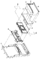
前面扉14の上部には、演出装置50が搭載されている。演出装置50の中央には、後述するリールの停止操作を促す促進報知や、エラー発生を報知するエラー報知や、ゲームに関連する各種演出を行なう表示画面を有する液晶表示器51が配置されている。また、液晶表示器51の表示画面の前面左右側方には、演出用の可動部材としての演出用扉60a、60bが左右方向にスライド移動自在に設けられている。演出用扉60a、60bは、各々、中央寄りの一辺の上端または下端に台形状の突出部と窪み部とが形成された平板から構成されている。演出用扉60a、60bの正面側には、その後面に配置される液晶表示器51の表示画面を視認不能にするための装飾が施されている。演出用扉60a、60bは、突出部と窪み部とが噛み合うようにして液晶表示器51の表示画面を隠蔽可能に構成されている。本実施例においては、この演出用扉60a、60bおよび液晶表示器51の双方を用いた各種演出が実施されるようになっており、この演出の一例として、たとえばゲームが開始されたときに、後述する内部抽選により当選した可能性がある入賞役を報知する予告演出として振動演出が実施されるようになっている。なお、演出装置50の構造の詳細、および演出装置50により行なわれる演出の詳細は後述する。
A
また、前面扉14の内側には、所定のキー操作により後述するRAM異常エラーを除くエラー状態および後述する打止状態を解除するためのリセット操作を検出するリセットスイッチ23、後述する設定値の変更中や設定値の確認中にその時点の設定値が表示される設定値表示器24、メダル投入部4から投入されたメダルの流路を、筐体内部に設けられた後述のホッパータンク(図示略)側またはメダル払出口9側のいずれか一方に選択的に切り替えるための流路切替ソレノイド30、メダル投入部4から投入され、ホッパータンク側に流下したメダルを検出する投入メダルセンサ31が設けられている。
Further, inside the
筐体内部には、前述したリール2L、2C、2R、リールモータ32L、32C、32R、各リール2L、2C、2Rのリール基準位置をそれぞれ検出可能なリールセンサ33からなるリールユニット(図示略)、メダル投入部4から投入されたメダルを貯留するホッパータンク(図示略)、ホッパータンクに貯留されたメダルをメダル払出口9より払い出すためのホッパーモータ34、ホッパーモータ34の駆動により払い出されたメダルを検出する払出センサ35、電源ボックス(図示略)が設けられている。
Inside the casing, a reel unit (not shown) comprising the
電源ボックスの前面には、後述のビッグボーナス終了時に打止状態(リセット操作がなされるまでゲームの進行が規制される状態)に制御する打止機能の有効/無効を選択するための打止スイッチ36、起動時に設定変更モードに切り替えるための設定キースイッチ37、通常時においてはRAM異常エラーを除くエラー状態や打止状態を解除するためのリセットスイッチとして機能し、設定変更モードにおいては後述する内部抽選の当選確率(出玉率)の設定値を変更するための設定スイッチとして機能するリセット/設定スイッチ38、電源をON/OFFする際に操作される電源スイッチ39が設けられている。
On the front of the power supply box is a stop switch for selecting whether to enable / disable a stop function for controlling the stop state (a state in which the progress of the game is restricted until a reset operation is performed) at the end of a big bonus, which will be described later 36, a setting
本実施例のスロットマシン1においてゲームを行なう場合には、まず、メダルをメダル投入部4から投入するか、あるいはクレジットを使用して賭数を設定する。クレジットを使用するには1枚BETスイッチ5、またはMAXBETスイッチ6を操作すればよい。遊技状態に応じて定められた規定数の賭数が設定されると、入賞ラインL1〜L5(図1参照)が有効となり、スタートスイッチ7の操作が有効な状態、すなわち、ゲームが開始可能な状態となる。なお、本実施例では、規定数の賭数として後述する通常遊技状態においては3枚が定められており、後述するレギュラーボーナス中においては、1枚が定められている。なお、遊技状態に対応する規定数を超えてメダルが投入された場合には、その分はクレジットに加算される。
When a game is played in the
ゲームが開始可能な状態でスタートスイッチ7を操作すると、各リール2L、2C、2Rが回転し、各リール2L、2C、2Rの図柄が連続的に変動する。この状態でいずれかのストップスイッチ8L、8C、8Rを操作すると、対応するリール2L、2C、2Rの回転が停止し、透視窓3に表示結果が導出表示される。
When the
そして全てのリール2L、2C、2Rが停止されることで1ゲームが終了し、有効化されたいずれかの入賞ラインL1〜L5上に予め定められた図柄の組合せ(以下、役とも呼ぶ)が各リール2L、2C、2Rの表示結果として停止した場合には入賞が発生し、その入賞に応じて定められた枚数のメダルが遊技者に対して付与され、クレジットに加算される。また、クレジットが上限数(本実施例では50)に達した場合には、メダルが直接メダル払出口9(図1参照)から払い出されるようになっている。なお、有効化された複数の入賞ライン上にメダルの払出を伴う図柄の組合せが揃った場合には、有効化された入賞ラインに揃った図柄の組合せそれぞれに対して定められた払出枚数を合計し、合計した枚数のメダルが遊技者に対して付与されることとなる。ただし、1ゲームで付与されるメダルの払出枚数には、上限(本実施例では、15枚)が定められており、合計した払出枚数が上限を超える場合には、上限枚数のメダルが付与されることとなる。また、有効化されたいずれかの入賞ラインL1〜L5上に、遊技状態の移行を伴う図柄の組合せが各リール2L、2C、2Rの表示結果として停止した場合には図柄の組合せに応じた遊技状態に移行するようになっている。
When one of the
また、本実施例におけるスロットマシン1にあっては、ゲームが開始されて各リール2L、2C、2Rが回転し、各可変表示部における図柄の変動が開始した後、ゲームが開始してから経過した時間に関わらず、いずれかのストップスイッチ8L、8C、8Rが操作されるまで、当該ストップスイッチ8L、8C、8Rに対応する可変表示部における図柄の変動が継続して行なわれるようになっている。
Further, in the
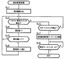
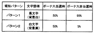
また、ゲームが開始してから、ストップスイッチ8L、8C、8Rが有効に操作されずに経過した時間が第1の報知待ち時間(本実施例では60秒)に到達したときに、ストップスイッチ8L、8C、8Rによるリール2L、2C、2Rの停止操作を促す促進報知としての報知画面(図24参照)が液晶表示器51に表示される。なお、該促進報知の実行中に、いずれかのストップスイッチ8L、8C、8Rが有効に操作されたときには、実行中の促進報知が終了されるようになっている。
In addition, when the time elapsed since the game started and the stop switches 8L, 8C, and 8R have not been operated effectively reaches the first notification waiting time (60 seconds in this embodiment), the
また、いずれかのリール2L、2C、2Rの回転が停止して可変表示部における図柄の変動が停止して表示結果が導出された後、未だ回転が停止されていないリール2L、2C、2Rがある場合、すなわち、表示結果が導出されていない可変表示部がある場合において、最後にストップスイッチ8L、8C、8Rが有効に操作されてから、ストップスイッチ8L、8C、8Rが有効に操作されずに経過した時間が前記第1の報知待ち時間(60秒)に到達したときにも、前記促進報知が実行される。
Further, after the rotation of any of the
なお、いずれかのリール2L、2C、2Rの回転が停止して可変表示部における図柄の変動が停止して表示結果が導出された後、未だ回転が停止されていないリール2L、2C、2Rがある場合において、当該ゲームにおいて既に促進報知が実行されている場合には、最後にストップスイッチ8L、8C、8Rが有効に操作されてから、ストップスイッチ8L、8C、8Rが有効に操作されずに経過した時間が第2の報知待ち時間(本実施例では30秒)に到達したときに前記促進報知が実行される。なお、促進報知の詳細に関しては後述することとする。
In addition, after the rotation of any of the
次に、図3〜図5を参照して、演出装置50の構造について説明する。図3(a)〜(f)は、各々、演出装置50の正面図、左側面図、右側面図、平面図、下面図、および背面図を示している。図4は、演出装置50の分解斜視図を示している。図5は、演出装置50の取付状態を説明するための分解斜視図を示している。
Next, the structure of the
まず、図3および図4を参照して、演出装置50は、左右方向にスライド可能な演出用扉60a、60bと、これらの演出用扉60a、60bを左右方向にスライド可能に保持する矩形状のベース部材70と、前述した液晶表示器51と、液晶表示器51をベース部材70に取付可能に構成するとともに液晶表示器51の後面側を被覆する液晶カバー部材72と、演出用扉60a、60bを左右方向にスライドさせるための演出用扉モータ56、57と、これらの演出用扉モータ56、57をベース部材70に取り付けるとともにベース部材70の後面側を被覆する後面カバー部材73と、演出用扉60a、60bの左右方向における位置を特定するための位置特定用センサ71a〜71dとを含む。演出装置50は、ベース部材70に上述した各種部材等が取り付けられて構成される。
First, referring to FIG. 3 and FIG. 4, the
演出用扉モータ56、57は、後面カバー部材73の後面側上方にビス止めされて取り付けられる。演出用扉モータ56、57の回転軸には、ホイールギア56a、57aが取り付けられる。
The
また、後面カバー部材73の後面側の左右には、複数の演出効果LED52を実装した演出効果LED用基板81a、81bを取り付けるための取付部が形成されており、演出効果LED用基板81a、81bがビス止めされて取り付けられる。取付部には、演出効果LED用基板81a、81bに実装されている複数の演出効果LED52の位置に合わせて通し穴が複数形成されている。これにより、演出効果LED用基板81a、81bを後面カバー部材73の後面側に取り付けた状態で、演出効果LEDからの光を前面側に放射させることができる。また、後面カバー部材73の前面上方の所定位置には、位置特定用センサ71a〜71dがビス止めされて取り付けられる。後面カバー部材73は、ベース部材70の後面側にビス止めされて取り付けられる。
Also, on the left and right sides of the rear surface side of the
ベース部材70の中央には、液晶表示器51の表示画面を臨ませるための表示領域用開口74が形成されている。液晶表示器51は、液晶カバー部材72に取り付け、該液晶カバー部材72をベース部材70の後面側に取り付けることにより、表示領域用開口74を介して遊技者が表示画面を視認可能な状態で固定される。なお、液晶カバー部材72の後面側には、後述する演出用中継基板90a、表示用中継基板190a、および液晶表示器51に含まれるバックライト用のインバータ基板51aを取り付けるための基板取付部が形成されている。
In the center of the
また、ベース部材70の上方には、上辺に沿って中央から左右端にわたり、演出用扉60a、60bを左右方向にスライド可能にするためのスライド用開口75a、75bが形成されている。また、ベース部材70の前面側には、スライド用開口75a、75bの下端に沿って、車輪部材77を支えるレール部78a、78bが形成されている。
Above the
演出用扉60a、60bの後面上部には、取付ボス76a〜76dが形成されている。取付ボス76a〜76dは、各々、車輪部材77の回転軸となるように軸状に形成されている。車輪部材77は、演出用扉60a、60bの取付ボス76a〜76d各々に回転可能に取り付けられる。演出用扉60a、60bは、取付ボス76a〜76dに車輪部材77が回転可能に取り付けられた状態で、車輪部材77を介してレール部78a、78b上に載置される。また、演出用扉60a、60bは、ベース部材70の後面側から扉取付用部材79a、79bに形成されたビス挿通穴から通されたビスが取付ボス76a〜76dに螺着されて、左右方向にスライド可能にベース部材70に取り付けられる。
Mounting bosses 76a to 76d are formed on rear upper portions of the
扉取付用部材79a、79b各々の下面には、演出用扉モータ56、57の回転軸に取り付けられているホイールギア56a、57aと噛み合うラックギアが形成されている。これにより、演出用扉60a、60bは、演出用扉モータ56、57により扉取付用部材79a、79bを左右にスライドさせることに応じて、レール部78a、78bに沿って左右にスライドする。たとえば、演出用扉60aは、演出用扉モータ56により扉取付用部材79aを左方向にスライドさせることにより、レール部78aに沿って左にスライドさせることができ、液晶表示器51の表示画面と重複しない位置に変位させることができる。一方、演出用扉60aは、演出用扉モータ56により扉取付用部材79aを右方向(中央寄り)にスライドさせることにより、レール部78aに沿って右にスライドさせることができ、液晶表示器51の表示画面と重複する位置に変位させることができる。演出用扉60bについても同様に、演出用扉モータ57により扉取付用部材79bを左右にスライドさせることにより、液晶表示器51の表示画面と重複しない位置と重複する位置とに変位させることができる。なお、重複しない位置とは、演出用扉60aを最も左方向にスライドさせ、演出用扉60aを最も右方向にスライドさせた図1に示す位置をいう。このような状態を開状態、または停止基準位置にある状態という。また、重複する位置とは、重複しない位置以外に演出用扉60a、60bをスライドさせた位置をいう。さらに、重複する位置のうち演出用扉60aを最も右方向にスライドさせ、演出用扉60aを最も左方向にスライドさせた位置にある状態を閉状態という。
On the lower surface of each of the
また、扉取付用部材79a、79bの上面には、位置特定用の突起部80a、80bが形成されている。前述した位置特定用センサ71a〜71dは、突起部80a、80bを検出することにより、演出用扉60a、60bの左右方向における位置を特定することができる。たとえば、位置特定用センサ71aは、演出用扉モータ56により演出用扉60aが最も左方向にスライドさせたときの位置特定用の突起部80aを検出する。また、位置特定用センサ71bは、演出用扉モータ56により演出用扉60aが最も右(中央)方向にスライドさせたときの位置特定用の突起部80aを検出する。同様に、位置特定用センサ71cは、演出用扉モータ57により演出用扉60bが最も左(中央)方向にスライドさせたときの位置特定用の突起部80bを検出する。また、位置特定用センサ71dは、演出用扉モータ57により演出用扉60bが最も右方向にスライドさせたときの位置特定用の突起部80bを検出する。
Further,
次に、図5を参照して、演出装置50の取付状態を説明する。演出装置50の前面側には、図5に示す部材が取り付けられる。ベース部材70の表示領域用開口74側方には、所定の模様が描かれた装飾用シール82a、82bが貼付される。また、ベース部材70の下方には、演出用扉60a、60bの下方端をベース部材70との間に挟み込んだ状態に維持するための押板83がビス止めされて取り付けられる。ベース部材70の前面には、さらに、演出用扉60a、60bが遊技者等により破損されることを防止する透明カバー板84がビス止めされて取り付けられる。さらに、ベース部材70の上方には、上辺に沿って左端から右端にわたり複数の演出効果LED52を実装した上部用演出効果LED用基板85がビス止めされて取り付けられる。ベース部材70の下方には、下辺に沿って左端から右端にわたり装飾体86がビス止めされて取り付けられる。
Next, with reference to FIG. 5, the mounting state of the
このように各種部材が取り付けられて構成される演出装置50は、左右および上の縁を被覆する表カバー部材87と、後面側を被覆する裏カバー部材88との間に挟み込むようにして一体的に組み付けられる。表カバー部材87の上部には、その後面側に配置されている上部用演出効果LED用基板85に実装されている複数の演出効果LED52からの光を前面に透過させるための透過部87aが形成されている。裏カバー部材88が前面扉14の後面側からビス止めされて取り付けられることにより、演出装置50が前面扉14の上部に取り付けられる。
The
図6は、スロットマシン1の構成を示すブロック図である。スロットマシン1には、図6に示すように、遊技制御基板40、演出制御基板90、表示制御基板190、電源基板100が設けられており、遊技制御基板40によって遊技状態が制御され、演出制御基板90によって遊技状態に応じた演出が制御され、表示制御基板190によって液晶表示器51の表示制御が行なわれ、電源基板100によってスロットマシン1を構成する電気部品の駆動電源が生成され、各部に供給される。
FIG. 6 is a block diagram showing the configuration of the
電源基板100には、外部からAC100Vの電源が供給されるとともに、このAC100Vの電源からスロットマシン1を構成する電気部品の駆動に必要な直流電圧が生成され、遊技制御基板40および遊技制御基板40を介して接続された演出制御基板90および該演出制御基板90に接続された表示制御基板190に供給されるようになっている。また、電源基板100には、前述したホッパーモータ34、払出センサ35、打止スイッチ36、設定キースイッチ37、リセット/設定スイッチ38、電源スイッチ39が接続されている。
The
遊技制御基板40には、前述した1枚BETスイッチ5、MAXBETスイッチ6、スタートスイッチ7、ストップスイッチ8L、8C、8R、精算スイッチ10、リセットスイッチ23、投入メダルセンサ31、リールセンサ33が接続されているとともに、電源基板100を介して前述した払出センサ35、打止スイッチ36、設定キースイッチ37、リセット/設定スイッチ38が接続されており、これら接続されたスイッチ類の検出信号が入力されるようになっている。
Connected to the
また、遊技制御基板40には、前述したクレジット表示器11、遊技補助表示器12、ペイアウト表示器13、1〜3BETLED14〜16、投入要求LED17、スタート有効LED18、ウェイト中LED19、リプレイ中LED20、BETスイッチ有効LED21、左、中、右停止有効LED22L、22C、22R、設定値表示器24、流路切替ソレノイド30、リールモータ32L、32C、32Rが接続されているとともに、電源基板100を介して前述したホッパーモータ34が接続されており、これら電気部品は、遊技制御基板40に搭載された後述のメイン制御部41の制御に基づいて駆動されるようになっている。
Further, the
遊技制御基板40には、CPU41a、ROM41b、RAM41c、I/Oポート41dを備えたマイクロコンピュータからなり、遊技の制御を行なうメイン制御部41、所定範囲(本実施例では0〜16383)の乱数を発生させる乱数発生回路42、乱数発生回路から乱数を取得するサンプリング回路43、遊技制御基板40に直接または電源基板100を介して接続されたスイッチ類から入力された検出信号を検出するスイッチ検出回路44、リールモータ32L、32C、32Rの駆動制御を行なうモータ駆動回路45、流路切替ソレノイド30の駆動制御を行なうソレノイド駆動回路46、遊技制御基板40に接続された各種表示器やLEDの駆動制御を行なうLED駆動回路47、スロットマシン1に供給される電源電圧を監視し、電圧低下を検出したときに、その旨を示す電圧低下信号をメイン制御部41に対して出力する電断検出回路48、電源投入時またはCPU41aからの初期化命令が入力されないときにCPU41aにリセット信号を与えるリセット回路49、その他各種デバイス、回路が搭載されている。
The
CPU41aは、計時機能、タイマ割込などの割込機能(割込禁止機能を含む)を備え、ROM41bに記憶されたプログラム(後述)を実行して、遊技の進行に関する処理を行なうととともに、遊技制御基板40に搭載された制御回路の各部を直接的または間接的に制御する。ROM41bは、CPU41aが実行するプログラムや各種テーブル等の固定的なデータを記憶する。RAM41cは、CPU41aがプログラムを実行する際のワーク領域等として使用される。I/Oポート41dは、メイン制御部41が備える信号入出力端子を介して接続された各回路との間で制御信号を入出力する。
The
メイン制御部41は、信号入力端子DATAを備えており、遊技制御基板40に接続された各種スイッチ類の検出状態がこれら信号入力端子DATAを介して入力ポートに入力される。これら信号入力端子DATAの入力状態は、CPU41aにより監視されており、CPU41aは、信号入力端子DATAの入力状態、すなわち各種スイッチ類の検出状態に応じて段階的に移行する基本処理を実行する。
The main control unit 41 includes a signal input terminal DATA, and detection states of various switches connected to the
また、CPU41aは、前述のように割込機能を備えており、割込の発生により基本処理に割り込んで割込処理を実行できるようになっている。本実施例では、割込1〜4の4種類の割込を実行可能であり、各割込毎にカウンタモード(信号入力端子DATAとは別個に設けられたトリガー端子CLK/TRGからの信号入力に応じて外部割込を発生させる割込モード)とタイマモード(CPU41aのクロック入力数に応じて内部割込を発生させる割込モード)のいずれかを選択して設定できるようになっている。
In addition, the
本実施例では、割込1〜4のうち、割込2がカウンタモードに設定され、割込3がタイマモードに設定され、割込1、4は未使用とされている。トリガー端子CLK/TRGは、前述した電断検出回路48と接続されており、CPU41aは電断検出回路48から出力された電圧低下信号の入力に応じて割込2を発生させて後述する電断割込処理を実行する。また、CPU41aは、クロック入力数が一定数に到達する毎、すなわち一定時間間隔(本実施例では、約0.56ms)毎に割込3を発生させて後述するタイマ割込処理(メイン)を実行する。また、割込1、4は、未使用に設定されているが、ノイズ等によって割込1、4が発生することがあり得る。このため、CPU41aは、割込1、4が発生した場合に、もとの処理に即時復帰させる未使用割込処理を実行するようになっている。
In the present embodiment, among the interrupts 1 to 4, interrupt 2 is set to the counter mode, interrupt 3 is set to the timer mode, and interrupts 1 and 4 are unused. The trigger terminal CLK / TRG is connected to the above-described power
また、CPU41aは、割込1〜4のいずれかの割込の発生に基づく割込処理の実行中に他の割込を禁止するように設定されているとともに、複数の割込が同時に発生した場合には、割込2、3、1、4の順番で優先して実行する割込が設定されている。すなわち割込2とその他の割込が同時に発生した場合には、割込2を優先して実行し、割込3と割込1または4が同時に発生した場合には、割込3を優先して実行するようになっている。
The
また、CPU41aは、割込1〜4のいずれかの割込の発生に基づく割込処理の開始時に、レジスタに格納されている使用中のデータをRAM41cに設けられた後述のスタック領域に一時的に退避させるとともに、当該割込処理の終了時にスタック領域に退避させたデータをレジスタに復帰させるようになっている。
Further, the
RAM41cには、DRAM(Dynamic RAM)が使用されており、記憶しているデータ
内容を維持するためのリフレッシュ動作が必要となる。CPU41aには、このリフレッシュ動作を行なうためのリフレッシュレジスタ41Rが設けられている。リフレッシュレジスタ41Rは、8ビットからなり、そのうちの下位7ビットが、CPU41aがROM41bから命令をフェッチする度に自動的にインクリメントされるもので、その値の更新は、1命令の実行時間毎に行なわれる。
As the
また、メイン制御部41には、停電時においてもバックアップ電源が供給されており、バックアップ電源が供給されている間は、CPU41aによりリフレッシュ動作が行なわれてRAM41cに記憶されているデータが保持されるようになっている。
The main control unit 41 is also supplied with backup power even during a power failure, and while the backup power is being supplied, the
乱数発生回路42は、後述するように所定数のパルスを発生する度にカウントアップして値を更新するカウンタによって構成され、サンプリング回路43は、乱数発生回路42がカウントしている数値を取得する。乱数発生回路42は、乱数の種類毎にカウントする数値の範囲が定められており、本実施例では、その範囲として0〜16383が定められている。CPU41aは、その処理に応じてサンプリング回路43に指示を送ることで、乱数発生回路42が示している数値を乱数として取得する(以下、この機能をハードウェア乱数機能という)。後述する内部抽選用の乱数は、ハードウェア乱数機能により抽出した乱数をそのまま使用するのではなく、ソフトウェアにより加工して使用するが、その詳細については詳しく説明する。また、CPU41aは、前述のタイマ割込処理(メイン)により、特定のレジスタの数値を更新し、こうして更新された数値を乱数として取得する機能も有する(以下、この機能をソフトウェア乱数機能という)。
The random
CPU41aは、I/Oポート41dを介して演出制御基板90に、各種のコマンドを送信する。遊技制御基板40から演出制御基板90へ送信されるコマンドは一方向のみで送られ、演出制御基板90から遊技制御基板40へ向けてコマンドが送られることはない。遊技制御基板40から演出制御基板90へ送信されるコマンドの伝送ラインは、ストローブ(INT)信号ライン、データ伝送ライン、グラウンドラインから構成されているとともに、演出中継基板80を介して接続されており、遊技制御基板40と演出制御基板90とが直接接続されない構成とされている。
The
演出制御基板90には、演出効果LED52、スピーカ53、54、リールLED55、演出用扉モータ56,57、位置特定用センサ71a〜71d等の電気部品が接続されており、これら電気部品は、演出制御基板90に搭載された後述のサブ制御部91による制御に基づいて駆動されるようになっている。なお、前述した演出効果LED用基板81a、81b、上部用演出効果LED用基板85、演出用扉モータ56、57、および位置特定用センサ71a〜71dは、演出用中継基板90aを介して演出制御基板90に接続される。
The
演出制御基板90には、メイン制御部41と同様にCPU91a、ROM91b、RAM91c、I/Oポート91dを備えたマイクロコンピュータにて構成され、演出の制御を行なうサブ制御部91、演出効果LED52およびリールLED55の駆動制御を行なうランプ駆動回路93、スピーカ53、54からの音声出力制御を行なう音声出力回路94、電源投入時またはCPU91aからの初期化命令が入力されないときにCPU91aにリセット信号を与えるリセット回路95、演出用扉モータ56,57の駆動制御を行なうモータ駆動回路96、その他の回路等、が搭載されており、CPU91aは、遊技制御基板40から送信されるコマンドを受けて、演出を行なうための各種の制御を行なうとともに、演出制御基板90に搭載された制御回路の各部を直接的または間接的に制御する。また、液晶表示器51による表示画像の表示を指示するコマンドを、I/Oポート91dを介して表示制御基板190に送信する。演出制御基板90から表示制御基板190へ送信されるコマンドは一方向のみで送られ、表示制御基板190から演出制御基板90へ向けてコマンドが送られることはない。
Like the main control unit 41, the
CPU91aは、メイン制御部41のCPU41aと同様に、タイマ割込などの割込機能(割込禁止機能を含む)を備える。サブ制御部91の割込端子(図示略)は、コマンド伝送ラインのうち、メイン制御部41がコマンドを送信する際に出力するストローブ(INT)信号線に接続されており、CPU91aは、ストローブ信号の入力に基づいて割込を発生させて、メイン制御部41からのコマンドを取得し、バッファに格納するコマンド受信割込処理を実行する。また、CPU91aは、クロック入力数が一定数に到達する毎、すなわち一定間隔毎に割込を発生させて後述するタイマ割込処理(サブ)を実行する。また、CPU91aにおいても未使用の割込が発生した場合には、もとの処理に即時復帰させる未使用割込処理を実行するようになっている。
Similar to the
また、CPU91aは、CPU41aとは異なり、ストローブ信号(INT)の入力に基づいて割込が発生した場合には、他の割込に基づく割込処理の実行中であっても、当該処理に割り込んでコマンド受信割込処理を実行し、他の割込が同時に発生してもコマンド受信割込処理を最優先で実行するようになっている。
Further, unlike the
また、サブ制御部91にも、停電時においてバックアップ電源が供給されており、バックアップ電源が供給されている間は、CPU91aによりリフレッシュ動作が行なわれてRAM91cに記憶されているデータが保持されるようになっている。
The
表示制御基板190には、スロットマシン1の前面扉14に配置された液晶表示器51(図1参照)が接続されており、該液晶表示器51は、表示制御基板190に搭載された後述の表示制御部191による制御に基づいて駆動されるようになっている。なお、前述した液晶表示器51は、表示用中継基板190aを介して表示制御基板190に接続される。前述した演出用中継基板90a、表示用中継基板190a、および液晶表示器51に含まれるバックライト用のインバータ基板51aは、前述した液晶カバー部材72の後面側に形成されている基板取付部に取り付けられる。
A liquid crystal display 51 (see FIG. 1) disposed on the
表示制御基板190には、メイン制御部41と同様にCPU191a、ROM191b、RAM191c、I/Oポート191dを備えたマイクロコンピュータにて構成され、演出制御基板90から送信されるコマンドに応じて、液晶表示器51の表示制御を行なう表示制御部191、液晶表示器51の駆動制御を行なう液晶駆動回路92、その他の回路等が搭載されており、CPU191aは、演出制御基板90から送信されるコマンドを受けて、液晶表示器51の表示制御を行なう。
The
また、表示制御部191にも、停電時においてバックアップ電源が供給されるようになっており、バックアップ電源が供給されている間は、CPU191aによりリフレッシュ動作が行なわれてRAM191cに記憶されているデータが保持されるようになっている。
The
本実施例のスロットマシン1は、設定値に応じてメダルの払出率が変わるものであり、後述する内部抽選の当選確率は、設定値に応じて定まるものとなる。以下、設定値の変更操作について説明する。
In the
設定値を変更するためには、設定キースイッチ37をON状態としてからスロットマシン1の電源をONする必要がある。設定キースイッチ37をON状態として電源をONすると、設定値表示器24に設定値の初期値として1が表示され、リセット/設定スイッチ38の操作による設定値の変更操作が可能な設定変更モードに移行する。設定変更モードにおいて、リセット/設定スイッチ38が操作されると、設定値表示器24に表示された設定値が1ずつ更新されていく(設定6から更に操作されたときは、設定1に戻る)。そして、スタートスイッチ7が操作されると設定値が確定し、確定した設定値がメイン制御部41のRAM41cに格納される。そして、設定キースイッチ37がOFFされると、遊技の進行が可能な状態に移行する。
In order to change the setting value, it is necessary to turn on the power of the
本実施例のスロットマシン1においては、メイン制御部41のCPU41aが電圧低下信号を検出した際に、電断割込処理を実行する。電断割込処理では、レジスタを後述するRAM41cのスタックに退避し、メイン制御部41のRAM41cにいずれかのビットが1となる破壊診断用データ(本実施例では、5AH)、すなわち0以外の特定のデータを格納するとともに、RAM41cの全ての領域に格納されたデータに基づくRAMパリティが0となるようにRAMパリティ調整用データを計算し、RAM41cに格納する処理を行なうようになっている。なお、RAMパリティとはRAM41cの該当する領域(本実施例では、全ての領域)の各ビットに格納されている値の排他的論理和として算出される値である。このため、RAM41cの全ての領域に格納されたデータに基づくRAMパリティが0であれば、RAMパリティ調整用データは0となり、RAM41cの全ての領域に格納されたデータに基づくRAMパリティが1であれば、RAMパリティ調整用データは1となる。
In the
そして、CPU41aは、その起動時においてRAM41cの全ての領域に格納されたデータに基づいてRAMパリティを計算するとともに、破壊診断用データの値を確認し、RAMパリティが0であり、かつ破壊診断用データの値も正しいことを条件に、RAM41cに記憶されているデータに基づいてCPU41aの処理状態を電断前の状態に復帰させるが、RAMパリティが0でない場合(1の場合)や破壊診断用データの値が正しくない場合には、RAM異常と判定し、RAM異常エラーコードをレジスタにセットしてRAM異常エラー状態に制御し、遊技の進行を不能化させるようになっている。なお、RAM異常エラー状態は、他のエラー状態と異なり、リセットスイッチ23やリセット/設定スイッチ38を操作しても解除されないようになっており、前述した設定変更モードにおいて新たな設定値が設定されるまで解除されることがない。
The
また、CPU41aは、後述する内部抽選処理において内部抽選に用いる設定値が適正な値であるか否かを判定する設定値判定処理を実行する。
Further, the
設定値判定処理では、内部抽選に用いる設定値が適正な範囲の値(1〜6)か否かを判定する設定値判定処理1、内部抽選に用いる設定値と、設定変更時に設定された設定値と、が一致するか否かを判定する設定値判定処理2、今回のゲームの内部抽選に用いる設定値と、前回のゲームの内部抽選に用いた設定値と、が一致するか否かを判定する設定値判定処理3、を1ゲーム毎にそれぞれ実行する。
In the set value determination process, the set
そして、設定値判定処理1において、内部抽選に用いる設定値が適正な範囲の値でない場合、または設定値判定処理2において、内部抽選に用いる設定値と、設定変更時に設定された設定値と、が一致しない場合、または設定値判定処理3において、今回のゲームの内部抽選に用いる設定値と、前回のゲームの内部抽選に用いた設定値と、が一致しない場合にも、RAM異常と判定し、RAM異常エラーコードをセットしてRAM異常エラー状態に制御し、遊技の進行を不能化させるようになっている。
In the setting
本実施例のスロットマシン1は、前述のように遊技状態に応じて設定可能な賭数の規定数が定められており、遊技状態に応じて定められた規定数の賭数が設定されたことを条件にゲームを開始させることが可能となる。本実施例では、賭数の規定数として3が定められている。このため、賭数として3が設定されるとゲームを開始させることが可能となる。なお、本実施例では、賭数として3が設定された時点で全ての入賞ラインL1〜L5が有効化されることとなる。
In the
本実施例のスロットマシン1は、全てのリール2L、2C、2Rが停止した際に、有効化された入賞ライン(本実施例の場合、常に全ての入賞ラインが有効化されるため、以下では、有効化された入賞ラインを単に入賞ラインと呼ぶ)上に役と呼ばれる図柄の組合せが揃うと入賞となる。入賞となる役の種類は、遊技状態に応じて定められているが、大きく分けて、メダルの払い出しを伴う小役と、賭数の設定を必要とせずに次のゲームを開始可能となる再遊技役と、遊技状態の移行を伴う特別役と、がある。遊技状態に応じて定められた各役の入賞が発生するためには、後述する内部抽選に当選して、当該役の当選フラグがRAM41cに設定されている必要がある。
In the
なお、これら各役の当選フラグのうち、小役および再遊技役の当選フラグは、当該フラグが設定されたゲームにおいてのみ有効とされ、次のゲームでは無効となるが、特別役の当選フラグは、当該フラグにより許容された役の組合せが揃うまで有効とされ、許容された役の組合せが揃ったゲームにおいて無効となる。すなわち特別役の当選フラグが一度当選すると、たとえ、当該フラグにより許容された役の組合せを揃えることができなかった場合にも、その当選フラグは無効とされずに、次のゲームへ持ち越されることとなる。 Of the winning flags for each of these roles, the winning flags for the small role and the replaying role are valid only in the game in which the flag is set, and are invalid in the next game. It is valid until a combination of combinations permitted by the flag is completed, and is invalid in a game having a combination of combinations permitted. In other words, once the special combination winning flag is won, even if the combination of the combination permitted by the flag cannot be made, the winning flag is not invalidated and is carried over to the next game. It becomes.
図7(a)は、遊技状態別当選役テーブルを示す図である。遊技状態別当選役テーブルは、メイン制御部41のROM41bに予め格納され、内部抽選において当選と判定される役を判断するために用いられるものであるが、遊技状態別当選役テーブルの登録内容は、遊技状態に応じて定められた役を示すものとなる。このスロットマシン1における役としては、特別役としてレギュラーボーナス、ビッグボーナス(1)、ビッグボーナス(2)が、小役としてチェリー、1枚(1)、1枚(2)、ベルが、再遊技役としてリプレイが定められている。
FIG. 7A is a diagram showing a winning combination table by gaming state. The gaming state winning combination table is stored in advance in the
レギュラーボーナスの遊技状態では、小役であるチェリー、1枚(1)、1枚(2)およびベルが、入賞となる役として定められており、レギュラーボーナスにおける内部抽選で抽選の対象とされる。通常遊技状態では、特別役であるレギュラーボーナス、ビッグボーナス(1)、ビッグボーナス(2)、小役であるチェリー、1枚(1)、1枚(2)およびベル、再遊技役であるリプレイが入賞となる役として定められており、通常遊技状態における内部抽選で抽選の対象とされる。 In the regular bonus game state, the small role cherry, 1 (1), 1 (2), and the bell are defined as winning roles and are subject to lottery in the internal lottery in the regular bonus. . In the normal gaming state, a regular bonus that is a special role, a big bonus (1), a big bonus (2), a cherry that is a small role, 1 (1), 1 (2) and a bell, and a replay that is a replaying role Is determined as a winning combination, and is a lottery target in an internal lottery in a normal gaming state.
チェリーは、いずれの遊技状態においても左リールについて入賞ラインのいずれかに「チェリー」の図柄が導出されたときに入賞となり、通常遊技状態においては2枚、レギュラーボーナスにおいては15枚のメダルが払い出される。なお、「チェリー」の図柄が左リールの上段または下段に停止した場合には、入賞ラインL2、L4または入賞ラインL3、L5の2本の入賞ラインにチェリーの組合せが揃うこととなり、2本の入賞ライン上でチェリーに入賞したこととなり、通常遊技状態においては4枚が払い出される。レギュラーボーナスにおいては合計枚数が30枚となるが、上限である15枚を超えるため、この場合には15枚が払い出される。1枚(1)は、いずれの遊技状態においても入賞ラインのいずれかに「青7−赤7−スイカ」の組合せが揃ったときに入賞となり、通常遊技状態においては1枚、レギュラーボーナスにおいては15枚のメダルが払い出される。1枚(2)は、いずれの遊技状態においても入賞ラインのいずれかに「赤7−青7−スイカ」の組合せが揃ったときに入賞となり、通常遊技状態においては1枚、レギュラーボーナスにおいては15枚のメダルが払い出される。ベルは、いずれの遊技状態においても入賞ラインのいずれかに「ベル−ベル−ベル」の組合せが揃ったときに入賞となり、通常遊技状態においては8枚、レギュラーボーナスにおいては15枚のメダルが払い出される。これらの小役が入賞したときのメダルの払い出しについては後述する。
Cherry is awarded when the “Cherry” symbol is derived on any of the winning lines for the left reel in any gaming state, and 2 medals are paid out in the normal gaming state and 15 in the regular bonus. It is. When the “cherry” symbol stops at the top or bottom of the left reel, the combination of cherries is aligned on the two pay lines L2, L4 or the pay lines L3, L5. It means that the cherries are won on the winning line, and 4 cards are paid out in the normal gaming state. In the regular bonus, the total number is 30, but exceeds the upper limit of 15, so in this case, 15 are paid out. One (1) will be awarded when the combination of “Blue 7-Red 7-Watermelon” is aligned on any of the winning lines in any gaming state, one in the normal gaming state, and in the
リプレイは、通常遊技状態において入賞ラインのいずれかに「リプレイ−リプレイ−リプレイ」の組合せが揃ったときに入賞となるが、レギュラーボーナスでは、この組合せが揃ったとしてもリプレイ入賞とならない。リプレイ入賞したときには、メダルの払い出しはないが次のゲームを改めて賭数を設定することなく開始できるので、次のゲームで設定不要となった賭数(レギュラーボーナスではリプレイ入賞しないので必ず3)に対応した3枚のメダルが払い出されるのと実質的には同じこととなる。 Replay is awarded when a combination of “Replay-Replay-Replay” is aligned on any of the winning lines in the normal gaming state, but with a regular bonus, even if this combination is aligned, no replay is awarded. When a replay is won, the medals will not be paid out, but the next game can be started without setting the number of bets again, so the number of bets no longer required to be set in the next game (the regular bonus will not be replayed and will always be 3) This is substantially the same as when three corresponding medals are paid out.
レギュラーボーナスは、通常遊技状態において入賞ラインのいずれかに「赤7−赤7−BAR」の組合せが揃ったときに入賞となる。レギュラーボーナス入賞すると、遊技状態が通常遊技状態からレギュラーボーナスに移行する。レギュラーボーナスは、12ゲームを消化したとき、または8ゲーム入賞(役の種類は、いずれでも可)したとき、のいずれか早いほうで終了する。遊技状態がレギュラーボーナスにある間は、レギュラーボーナス中フラグがRAM41cに設定される。
The regular bonus is awarded when a combination of “red 7-red 7-BAR” is arranged on any of the winning lines in the normal gaming state. When the regular bonus is won, the gaming state shifts from the normal gaming state to the regular bonus. The regular bonus ends when 12 games are consumed, or when 8 games are won (any kind of combination is possible), whichever comes first. While the game state is in the regular bonus, the regular bonus medium flag is set in the
ビッグボーナスは、通常遊技状態において入賞ラインのいずれかに「赤7−赤7−赤7」の組合せ、または「青7−青7−青7」の組合せが揃ったときに入賞となる。ビッグボーナス入賞すると、遊技状態がビッグボーナスに移行する。ビッグボーナスに移行すると、ビッグボーナスへの移行と同時にレギュラーボーナスに移行し、レギュラーボーナスが終了した際に、ビッグボーナスが終了していなければ、再度レギュラーボーナスに移行し、ビッグボーナスが終了するまで繰り返しレギュラーボーナスに制御される。すなわちビッグボーナス中は、常にレギュラーボーナスに制御されることとなる。そして、ビッグボーナスは、当該ビッグボーナス中において遊技者に払い出したメダルの総数が466枚に達したときに終了する。この際、レギュラーボーナスの終了条件が成立しているか否かに関わらずレギュラーボーナスも終了する。遊技状態がビッグボーナスにある間は、ビッグボーナス中フラグがRAM41cに設定される。
The big bonus is awarded when a combination of “red 7-red 7-
なお、「赤7−赤7−赤7」によるビッグボーナスおよび「青7−青7−青7」によるビッグボーナスを区別する必要がある場合には、それぞれビッグボーナス(1)、ビッグボーナス(2)と呼ぶものとする。また、前述したレギュラーボーナス、ビッグボーナス(1)およびビッグボーナス(2)をまとめて、単に「ボーナス」と呼ぶ場合があるものとする。
When it is necessary to distinguish between the big bonus by “red 7-red 7-
以下、内部抽選について説明する。内部抽選は、上記した各役への入賞を許容するかどうかを、全てのリール2L、2C、2Rの表示結果が導出表示される以前に(実際には、スタートスイッチ7の検出時)、決定するものである。内部抽選では、まず、内部抽選用の乱数(0〜16383の整数)が取得される。そして、遊技状態に応じて定められた各役について、取得した内部抽選用の乱数と、遊技者が設定した賭数と、設定値に応じて定められた各役の判定値数に応じて行なわれる。
Hereinafter, the internal lottery will be described. The internal lottery decides whether or not the winning of each winning combination is allowed before the display results of all the
遊技状態に応じた役の参照は、図7(a)に示した遊技状態別役テーブルに応じて行なわれる。遊技状態がレギュラーボーナス(ビッグボーナス中に提供された場合を含む)にあるときには、チェリー、1枚(1)、1枚(2)、ベルが内部抽選の対象役として順に読み出され、遊技状態が通常遊技状態にあるときには、レギュラーボーナス、ビッグボーナス(1)、ビッグボーナス(2)、チェリー、1枚(1)、1枚(2)、ベル、リプレイが内部抽選の対象役として順に読み出される。もっとも、前回以前のゲームでレギュラーボーナス、ビッグボーナス(1)、ビッグボーナス(2)の当選フラグが設定され、当該フラグに基づく入賞が発生しないで持ち越されているときには、レギュラーボーナス、ビッグボーナス(1)、ビッグボーナス(2)は、内部抽選の対象役となることはない。 The reference of the combination according to the game state is performed according to the combination table according to the game state shown in FIG. When the gaming state is a regular bonus (including the case where the bonus is provided during the big bonus), the cherry, 1 (1), 1 (2), and bell are read in order as the internal lottery target roles, and the gaming state Is in the normal gaming state, the regular bonus, big bonus (1), big bonus (2), cherry, 1 (1), 1 (2), bell, and replay are sequentially read out as the target for internal lottery. . However, if the winning flag of the regular bonus, the big bonus (1), or the big bonus (2) is set in the game before the previous game, and the game is carried over without winning based on the flag, the regular bonus, the big bonus (1 ), Big Bonus (2) will not be a target for internal lottery.
内部抽選では、内部抽選の対象役について定められた判定値数を、内部抽選用の乱数に順次加算し、加算の結果がオーバーフローしたときに、当該役に当選したものと判定される。当選と判定されると、当該役の当選フラグがメイン制御部41のRAM41cに設定される。判定値数は、メイン制御部41のROMに予め格納された役別テーブルに登録されている判定値数の格納アドレスに従って読み出されるものとなる。
In the internal lottery, the number of determination values determined for the internal lottery target combination is sequentially added to the internal lottery random number, and when the addition result overflows, it is determined that the winning combination is won. When the winning is determined, the winning flag of the combination is set in the
図7(b)は、役別テーブルの例を示す図である。判定値数は、その値が256以上になるものもあり、1バイト分では記憶できないので、判定値数毎に2バイト分の記憶領域を用いて登録されるものとなる。 FIG. 7B is a diagram illustrating an example of the role-specific table. The number of determination values may be 256 or more, and cannot be stored in one byte. Therefore, each determination value number is registered using a storage area of 2 bytes.
各役の判定値数は、遊技者が設定する賭数(BET)に対応して登録されている。同一の役であっても、賭数に応じて当選確率が異なっている場合があるからである。また、各役の賭数に応じた判定値数は、設定値に関わらずに共通になっているものと、設定値に応じて異なっているものとがある。判定値数が設定値に関わらずに共通である場合には、共通フラグが設定される(値が「1」とされる)。 The number of determination values for each combination is registered corresponding to the number of bets (BET) set by the player. This is because even if they have the same combination, the winning probabilities may differ depending on the number of bets. In addition, the number of determination values according to the number of bets for each combination may be common regardless of the set value, or may be different depending on the set value. If the number of determination values is common regardless of the set value, a common flag is set (value is set to “1”).
役別テーブルには、図7(b)に示すように、レギュラーボーナス、ビッグボーナス(1)、ビッグボーナス(2)、チェリー、1枚(1)、1枚(2)、ベル、リプレイの判定値数の格納アドレスが登録されている。 In the role table, as shown in FIG. 7B, regular bonus, big bonus (1), big bonus (2), cherry, 1 (1), 1 (2), bell, replay determination The storage address for the number of values is registered.
レギュラーボーナスは、通常遊技状態において内部抽選の対象となる役であり、通常遊技状態に対応する判定値数の格納アドレスとが登録されている。レギュラーボーナスについては、共通フラグが0となっており、設定値に応じて個別に判定値数の格納アドレスが登録されている。 The regular bonus is a role that is an object of an internal lottery in the normal gaming state, and a storage address for the number of determination values corresponding to the normal gaming state is registered. For the regular bonus, the common flag is 0, and the storage address for the number of determination values is individually registered according to the set value.
ビッグボーナス(1)、ビッグボーナス(2)は、通常遊技状態において内部抽選の対象となる役であり、通常遊技状態に対応する判定値数の格納アドレスとが登録されている。ビッグボーナス(1)、ビッグボーナス(2)については、共通フラグが0となっており、設定値に応じて個別に判定値数の格納アドレスが登録されている。 The big bonus (1) and the big bonus (2) are roles that are subject to internal lottery in the normal gaming state, and the storage addresses of the number of determination values corresponding to the normal gaming state are registered. For the big bonus (1) and the big bonus (2), the common flag is 0, and the storage address for the number of determination values is individually registered according to the set value.
チェリー、1枚(1)、1枚(2)およびベルは、レギュラーボーナスおよび通常遊技状態のいずれの遊技状態においても内部抽選の対象となる役であり、レギュラーボーナスに対応する判定値数の格納アドレスと、通常遊技状態に対応する判定値数の格納アドレスと、が登録されている。チェリー、1枚(1)、1枚(2)については、共通フラグが1となっており、それぞれの遊技状態に応じて設定値に関わらず共通の判定値数の格納アドレスが登録されている。ベルについては、共通フラグが0となっており、それぞれの遊技状態および設定値に応じて個別に判定値数の格納アドレスが登録されている。 Cherry, 1 (1), 1 (2), and bell are roles that are subject to internal lottery in both the regular bonus and the normal gaming state, and store the number of judgment values corresponding to the regular bonus An address and a storage address for the number of determination values corresponding to the normal gaming state are registered. For Cherry, 1 (1), 1 (2), the common flag is 1, and the storage address of the common number of judgment values is registered regardless of the set value according to each gaming state. . For the bell, the common flag is 0, and the storage address of the determination value number is individually registered according to each game state and the set value.
リプレイは、通常遊技状態において内部抽選の対象となる役であり、通常遊技状態に対応する判定値数の格納アドレスが登録されている。この役の共通フラグは1であり、設定値に関わらず共通の判定値数の格納アドレスが登録されている。 Replay is a role that is a target of internal lottery in the normal gaming state, and a storage address for the number of determination values corresponding to the normal gaming state is registered. The common flag for this combination is 1, and a common storage address for the number of determination values is registered regardless of the set value.
また、役別テーブルには、各役に入賞したときに払い出されるメダルの払出枚数も登録されている。もっとも、入賞したときにメダルの払い出し対象となる役は、小役であるチェリー、1枚(1)、1枚(2)およびベルだけである。チェリー、1枚(1)、1枚(2)およびベルは、遊技状態に関わらず入賞が発生可能であるが、これらの役については、遊技状態がレギュラーボーナスにあるときには、遊技状態が通常遊技状態にあるときよりも多いメダルが払い出されるものとなる。また、左リールの上段または下段に「チェリー」が停止した場合には、前述のように2本の入賞ラインにチェリーの組合せが揃ったこととなるため、それぞれの払出枚数の合計枚数が払い出されることとなる。本実施例では、通常遊技状態においてチェリーの払出枚数が2枚であるため、4枚のメダルが払い出される。レギュラーボーナスでは、チェリーの払出枚数が15枚であるが、合計枚数が上限である15枚を超えるため、この場合には15枚のメダルが払い出される。 Also, the number of medals to be paid out when winning each winning combination is registered in the role-specific table. However, only the cherry, which is a small role, 1 (1), 1 (2), and a bell, are the targets for paying out medals when winning a prize. Cherry, 1 (1), 1 (2), and Bell can be awarded regardless of the gaming state, but for these roles, when the gaming state is a regular bonus, the gaming state is normal gaming. More medals will be paid out than when in the state. Further, when “cherry” stops at the upper or lower stage of the left reel, the combination of cherries is aligned on the two pay lines as described above, so the total number of payouts is paid out. It will be. In this embodiment, since the number of cherries paid out is 2 in the normal gaming state, 4 medals are paid out. In the regular bonus, the number of cherries paid out is 15, but the total number exceeds the upper limit of 15, so in this case, 15 medals are paid out.
レギュラーボーナス、ビッグボーナス(1)、ビッグボーナス(2)の入賞は、遊技状態の移行を伴うものであり、メダルの払い出し対象とはならない。リプレイでは、メダルの払い出しを伴わないが、次のゲーム(必ず通常遊技状態)で賭数の設定に用いメダルの投入が不要となるので実質的には3枚の払い出しと変わらない。 The regular bonus, the big bonus (1), and the big bonus (2) are accompanied by a transition of the gaming state, and are not eligible for payout of medals. The replay does not involve paying out medals, but it is substantially the same as paying out 3 medals because it is not necessary to insert medals for setting the number of bets in the next game (always the normal gaming state).
図8は、役別テーブルに登録されたアドレスに基づいて取得される判定値数の記憶領域を示す図である。この判定値数の記憶領域は、開発用の機種ではメイン制御部41のRAM41cに、量産機種ではメイン制御部41のROM41bに割り当てられたアドレス領域に設けられている。
FIG. 8 is a diagram illustrating a storage area for the number of determination values acquired based on the addresses registered in the role-specific table. The storage area for the number of determination values is provided in the
たとえばアドレスADD+74は、内部抽選の対象役がリプレイであるときに賭数および設定値に関わらずに参照されるアドレスであり、賭数および設定値に関わらずに、2245が判定値数として取得される。 For example, the address ADD + 74 is an address that is referred to regardless of the number of bets and the set value when the target role of the internal lottery is replay, and 2245 is acquired as the number of determination values regardless of the number of bets and the set value. The
アドレスADDは、通常遊技状態において内部抽選の対象役がレギュラーボーナスであって設定値が1のときに参照されるアドレスであり、このときには、ここに格納された値である31が判定値数として取得される。アドレスADD+2、ADD+4、ADD+6、ADD+8、ADD+10は、それぞれ通常遊技状態において内部抽選の対象役がレギュラーボーナスであって設定値が2〜6のときに参照されるアドレスである。レギュラーボーナスについては、設定値に応じて個別に判定値数が記憶されているが、同一の判定値数が記憶されているので、いずれの設定値においてもレギュラーボーナスの当選確率は同じとなっている。 The address ADD is an address that is referred to when the target character of the internal lottery is a regular bonus and the set value is 1 in the normal gaming state. At this time, 31 stored as the value is the number of determination values. To be acquired. The addresses ADD + 2, ADD + 4, ADD + 6, ADD + 8, and ADD + 10 are addresses that are referred to when the target character of the internal lottery is a regular bonus and the set value is 2 to 6 in the normal gaming state. Regarding the regular bonus, the number of judgment values is individually stored according to the set value, but since the same number of judgment values is stored, the winning probability of the regular bonus is the same at any set value. Yes.
アドレスADD+12、ADD+14、ADD+16、ADD+18、ADD+20、ADD+22は、それぞれ通常遊技状態において内部抽選の対象役がビッグボーナス(1)であって設定値が1〜6のときに参照されるアドレスである。アドレスADD+24、ADD+26、ADD+28、ADD+30、ADD+32、ADD+34は、それぞれ通常遊技状態において内部抽選の対象役がビッグボーナス(2)であって設定値が1〜6のときに参照されるアドレスである。ビッグボーナス(1)、ビッグボーナス(2)については、判定値数が、設定値に応じて個別に記憶され、しかも異なる判定値数が記憶されているので、設定値に応じて当選確率が異なることとなる。 Addresses ADD + 12, ADD + 14, ADD + 16, ADD + 18, ADD + 20, and ADD + 22 are addresses that are referred to when the target character of the internal lottery is the big bonus (1) and the set value is 1 to 6 in the normal gaming state. Addresses ADD + 24, ADD + 26, ADD + 28, ADD + 30, ADD + 32, and ADD + 34 are addresses that are referred to when the target character of the internal lottery is the big bonus (2) and the set value is 1 to 6, respectively. For the big bonus (1) and the big bonus (2), the number of determination values is stored individually according to the set value, and different determination value numbers are stored, so that the winning probabilities differ according to the set value. It will be.
アドレスADD+38は、レギュラーボーナスにおいて内部抽選の対象役がチェリーであるときに設定値に関わらずに参照されるアドレスである。アドレスADD+40は、通常遊技状態において内部抽選の対象役がチェリーであるときに設定値に関わらず参照されるアドレスである。チェリーについての判定値数は、賭数に応じて登録されているが、同じ値が登録されているので、レギュラーボーナスであるか、通常遊技状態であるかに関わらずチェリーの当選確率は同じとなる。1枚(1)についても、アドレスADD+42、ADD+44に同様にして判定値数が登録されており、1枚(2)についても、アドレスADD+46、ADD+48に同様にして判定値数が登録されている。 The address ADD + 38 is an address that is referred to regardless of the set value when the target part of the internal lottery is cherry in the regular bonus. The address ADD + 40 is an address that is referred to regardless of the set value when the target character of the internal lottery is cherry in the normal gaming state. The number of judgment values for cherry is registered according to the number of bets, but since the same value is registered, the winning probability of cherry is the same regardless of whether it is a regular bonus or a normal gaming state Become. The number of determination values is also registered in the same way for addresses ADD + 42 and ADD + 44 for one sheet (1), and the number of determination values is also registered for addresses ADD + 46 and ADD + 48 for one sheet (2).
アドレスADD+50、ADD+52、ADD+54、ADD+56、ADD+58、ADD+60は、それぞれレギュラーボーナスにおいて内部抽選の対象役がベルであって設定値が1〜6のときに参照されるアドレスである。アドレスADD+50とADD+52、ADD+54とADD+56、ADD+58とADD+60には、それぞれ同一の値が登録されているので、レギュラーボーナス時においては、設定値1と設定値2、設定値3と設定値4、設定値5と設定値6とで、ベルの当選確率が同一となる。
The addresses ADD + 50, ADD + 52, ADD + 54, ADD + 56, ADD + 58, and ADD + 60 are addresses that are referred to when the target character of the internal lottery is a bell and the set value is 1 to 6 in the regular bonus. Since the same value is registered in each of the addresses ADD + 50 and ADD + 52, ADD + 54 and ADD + 56, and ADD + 58 and ADD + 60, the
アドレスADD+62、ADD+64、ADD+66、ADD+68、ADD+70、ADD+72は、それぞれ通常遊技状態において内部抽選の対象役がベルであって設定値が1〜6のときに参照されるアドレスである。アドレスADD+62、ADD+64、ADD+66、ADD+68、ADD+70、ADD+72には、互いに異なる値が登録されているので、通常遊技状態においては、設定値に応じてベルの当選確率が異なることとなる。 Addresses ADD + 62, ADD + 64, ADD + 66, ADD + 68, ADD + 70, and ADD + 72 are addresses that are referred to when the internal lottery target role is a bell and the set value is 1 to 6, respectively. Since different values are registered in the addresses ADD + 62, ADD + 64, ADD + 66, ADD + 68, ADD + 70, and ADD + 72, the winning probability of the bell differs depending on the set value in the normal gaming state.
図9および図10は、内部抽選用の乱数の値および各役の判定値数と、当選役との関係の例を示す図である。図9では通常遊技状態にあるときの、図10ではレギュラーボーナス中にあるときの例を示している。図9および図10のいずれも、設定値が6の場合の例を示しており、またレギュラーボーナス、ビッグボーナスのいずれの当選フラグも設定されてない場合の例を示している。 FIG. 9 and FIG. 10 are diagrams showing an example of the relationship between the value of the random number for internal lottery and the number of determination values of each combination and the winning combination. FIG. 9 shows an example in a normal gaming state, and FIG. 10 shows an example in a regular bonus. Both FIG. 9 and FIG. 10 show an example when the set value is 6, and also show an example when neither of the regular bonus and the big bonus winning flag is set.
たとえば、図9に示すように、通常遊技状態では、内部抽選の対象役となる役は、レギュラーボーナス、ビッグボーナス(1)、ビッグボーナス(2)、チェリー、1枚(1)、1枚(2)、ベル、リプレイであり、設定値6においては、それぞれの判定値数は、31、20、40、96、163、163、2082、2245となる。最初に内部抽選の対象役となるレギュラーボーナスは、判定値数の31を加算することで加算結果がオーバーフローすることとなる16353〜16383が内部抽選用の乱数として取得されたときに当選となる。
For example, as shown in FIG. 9, in the normal gaming state, the roles that are subject to the internal lottery are regular bonus, big bonus (1), big bonus (2), cherry, 1 (1), 1 ( 2) Bell and replay. In the setting
次に内部抽選の対象役となるビッグボーナス(1)は、レギュラーボーナスの判定値数31とビッグボーナス(1)の判定値数20とを合計した51を加算することで加算結果がオーバーフローすることとなる16333〜16352が内部抽選用の乱数として取得されたときに当選となる。同様に、ビッグボーナス(2)は、16293〜16332が内部抽選用の乱数として取得されたときに、チェリーは、16197〜16292が内部抽選用の乱数として取得されたときに、1枚(1)は、16034〜16196が内部抽選用の乱数として取得されたときに、1枚(2)は、15871〜16033が内部抽選用の乱数として取得されたときに、ベルは、13789〜15870が内部抽選用の乱数として取得されたときに、リプレイは、11544〜13788が内部抽選用の乱数として取得されたときに、それぞれ当選と判定される。
Next, for the big bonus (1) that is the subject of the internal lottery, the addition result overflows by adding 51, which is the sum of the regular bonus
これらの判定値数に基づいて算出される各役のおおよその当選確率は、レギュラーボーナス(1)、ビッグボーナス(1)、ビッグボーナス(2)、チェリー、1枚(1)、1枚(2)、ベル、リプレイのそれぞれについて、1/528.5、1/819.2、1/409.6、1/170.1、1/100.5、1/100.5、1/7.9、1/7.3となる。なお、0〜11543が内部抽選用の乱数として取得されたときには、全ての役にハズレとなる。 The approximate winning probabilities calculated for each combination based on the number of judgment values are as follows: regular bonus (1), big bonus (1), big bonus (2), cherry, 1 (1), 1 (2 ), Bell and Replay, 1 / 528.5, 1 / 819.2, 1 / 409.6, 1 / 170.1, 1 / 100.5, 1 / 100.5, 1 / 7.9 1 / 7.3. When 0-11543 is acquired as a random number for internal lottery, all combinations are lost.
また、図10に示すように、レギュラーボーナスでは、チェリー、1枚(1)、1枚(2)、ベルが内部抽選の対象役となり、それぞれの判定値数が96、163、163、15919であるので、16288〜16383、16125〜16287、15962〜16124、43〜15961が内部抽選用の乱数として取得されたときに、当選と判定される。また、それぞれの役のおおよその当選確率は、1/170.1、1/100.5、1/100.5、1/1.03となる。なお、0〜42が内部抽選用の乱数として取得されたときには、全ての役にハズレとなる。これらの内部抽選用の乱数は、ハードウェア乱数機能により乱数発生回路42から乱数を抽出し、これをCPU41aがソフトウェアによって加工することによって取得されるものとなる。
In addition, as shown in FIG. 10, in the regular bonus, cherry, 1 (1), 1 (2), and bell are subject to the internal lottery, and the number of determination values is 96, 163, 163, 15919, respectively. Therefore, when 16288 to 16383, 16125 to 16287, 15962 to 16124, and 43 to 15961 are acquired as random numbers for internal lottery, it is determined that the winning is made. Further, the approximate winning probabilities of the respective combinations are 1 / 17.01, 1 / 100.5, 1 / 100.5, and 1 / 1.03. When 0 to 42 are acquired as random numbers for internal lottery, all combinations are lost. These random numbers for internal lottery are acquired by extracting a random number from the random
次に、リール2L、2C、2Rの停止制御について説明する。CPU41aは、リールの回転が開始したとき、および、リールが停止しかつ未だ回転中のリールが残っているときに、ROM41bに格納されているテーブルインデックスおよびテーブル作成用データを参照して、回転中のリール別に停止制御テーブルを作成する。そして、ストップスイッチ8L、8C、8Rのうち、回転中のリールに対応するいずれかの操作が有効に検出されたときに、該当するリールの停止制御テーブルを参照し、参照した停止制御テーブルの引込コマ数に基づいて、操作されたストップスイッチ8L、8C、8Rに対応するリール2L、2C、2Rの回転を停止させる制御を行なう。
Next, stop control of the
テーブルインデックスには、図11に示すように、各遊技状態について内部抽選による当選フラグの設定状態(以下、内部当選状態と呼ぶ)別に、テーブル作成用データが格納された領域の先頭アドレスが格納されている。 As shown in FIG. 11, the table index stores the start address of the area in which the data for table creation is stored for each gaming state, according to the setting state of the winning flag by internal lottery (hereinafter referred to as the internal winning state). ing.
具体的には、通常遊技状態においては、チェリー、1枚(1)、1枚(2)、ベル、リプレイ、ビッグボーナス(1)(+ハズレ)、ビッグボーナス(1)+チェリー、ビッグボーナス(1)+1枚(1)、ビッグボーナス(1)+1枚(2)、ビッグボーナス(1)+ベル、ビッグボーナス(1)+リプレイ、ビッグボーナス(2)(+ハズレ)、ビッグボーナス(2)+チェリー、ビッグボーナス(2)+1枚(1)、ビッグボーナス(2)+1枚(2)、ビッグボーナス(2)+ベル、ビッグボーナス(2)+リプレイ、レギュラーボーナス(+ハズレ)、レギュラーボーナス+チェリー、レギュラーボーナス+1枚(1)、レギュラーボーナス+1枚(2)、レギュラーボーナス+ベル、レギュラーボーナス+リプレイ、ハズレのそれぞれについて、テーブル作成用データが格納された領域の先頭アドレスが格納され、レギュラーボーナスについては、チェリー、1枚(1)、1枚(2)、ベル、ハズレのそれぞれについて、テーブル作成用データが格納された領域の先頭アドレスが格納されている。なお、遊技状態が異なったり、役の当選状況が異なったりする場合でも、同一の制御が適用される場合(たとえば、通常遊技状態におけるチェリー当選時と、レギュラーボーナスにおけるチェリー当選時と、で同一の制御を適用する場合や、ビッグボーナス(1)+リプレイ当選時と、ビッグボーナス(2)+リプレイ当選時と、レギュラーボーナス+リプレイ当選時と、で同一の制御を適用する場合など)においては、テーブル作成用データが格納された領域の先頭アドレスとして同一のアドレスが格納されており、このような場合には、同一のテーブル作成用データを参照して、停止制御テーブルが作成されることとなる。 Specifically, in the normal gaming state, cherry, 1 (1), 1 (2), bell, replay, big bonus (1) (+ lose), big bonus (1) + cherry, big bonus ( 1) +1 (1), Big Bonus (1) + 1 (2), Big Bonus (1) + Bell, Big Bonus (1) + Replay, Big Bonus (2) (+ Loss), Big Bonus (2) + Cherry, Big Bonus (2) + 1 (1), Big Bonus (2) + 1 (2), Big Bonus (2) + Bell, Big Bonus (2) + Replay, Regular Bonus (+ Loss), Regular Bonus + Cherry, regular bonus + 1 (1), regular bonus + 1 (2), regular bonus + bell, regular bonus + replay, loser For each, the top address of the area where the table creation data is stored is stored, and for the regular bonus, the table creation data for each of cherry, 1 (1), 1 (2), bell, and lose The start address of the area in which is stored is stored. Even if the game state is different or the winning situation of the combination is different, the same control is applied (for example, the same in the cherry winning in the normal gaming state and the cherry winning in the regular bonus) In the case of applying the control, or in the case of applying the same control for the big bonus (1) + replay winning, the big bonus (2) + replay winning, and the regular bonus + replay winning) The same address is stored as the start address of the area where the table creation data is stored. In such a case, the stop control table is created with reference to the same table creation data. .
テーブル作成用データは、停止操作位置に応じた引込コマ数を示す引込コマ数データと、リールの停止状況に応じて参照すべき引込コマ数データのアドレスと、からなる。 The table creation data is composed of drawn-in frame number data indicating the number of drawn-in frames corresponding to the stop operation position, and an address of drawn-in frame number data to be referred to in accordance with the reel stop status.
リールの停止状況に応じて参照される引込コマ数データは、全てのリールが回転しているか、左リールのみ停止しているか、中リールのみ停止しているか、右リールのみ停止しているか、左、中リールが停止しているか、左、右リールが停止しているか、中、右リールが停止しているか、によって異なる場合があり、更に、いずれかのリールが停止している状況においては、停止済みのリールの停止位置によっても異なる場合があるので、それぞれの状況について、参照すべき引込コマ数データのアドレスが回転中のリール別に登録されており、テーブル作成用データの先頭アドレスに基づいて、それぞれの状況に応じて参照すべき引込コマ数データのアドレスが特定可能とされ、この特定されたアドレスから、それぞれの状況に応じて必要な引込コマ数データを特定できるようになっている。なお、リールの停止状況や停止済みのリールの停止位置が異なる場合でも、同一の引込コマ数データが適用される場合においては、引込コマ数データのアドレスとして同一のアドレスが登録されているものもあり、このような場合には、同一の引込コマ数データが参照されることとなる。 The number-of-drawing frame data referenced according to the reel stop status is whether all reels are rotating, only the left reel is stopped, only the middle reel is stopped, only the right reel is stopped, or left Depending on whether the middle reel is stopped, the left and right reels are stopped, the middle and right reels are stopped, and in the situation where any one of the reels is stopped, Since it may vary depending on the stop position of the stopped reel, the address of the number of frames to be drawn to be referred to is registered for each rotating reel for each situation, and based on the top address of the table creation data , It is possible to specify the address of the number of frames data to be referred to according to each situation, and it is necessary according to each situation from this identified address. It has to be able to identify the lead-frame number data. Even if the reel stop status and the stop position of the stopped reel are different, the same address is registered as the address of the number of frames to be drawn when the same number of frames to be drawn is applied. In such a case, the same data for the number of drawn frames is referred to.
引込コマ数データは、停止操作が行なわれたタイミング別の引込コマ数を特定可能なデータである。本実施例では、リールモータ32L、32C、32Rに、168ステップ(0〜167)の周期で1周するステッピングモータを用いている。すなわちリールモータ32L、32C、32Rを168ステップ駆動させることでリール2L、2C、2Rが1周することとなる。そして、特に図示はしないが、リール1周に対して8ステップ(1図柄が移動するステップ数)毎に分割した21の領域(コマ)が定められており、これらの領域には、リール基準位置から1〜21の領域番号が割り当てられている。一方、1リールに配列された図柄数も21であり、各リールの図柄に対して、リール基準位置から1〜21の図柄番号が割り当てられているので、1番図柄から21番図柄に対して、それぞれ1〜21の領域番号が順に割り当てられていることとなる。そして、引込コマ数データには、領域番号別の引込コマ数が所定のルールで圧縮して格納されており、引込コマ数データを展開することによって領域番号別の引込コマ数を取得できるようになっている。
The drawn frame number data is data that can specify the number of drawn frames for each timing at which the stop operation is performed. In this embodiment, stepping motors that make one turn at a cycle of 168 steps (0 to 167) are used for the reel motors 32L, 32C, and 32R. That is, when the reel motors 32L, 32C, and 32R are driven for 168 steps, the
前述のようにテーブルインデックスおよびテーブル作成用データを参照して作成される停止制御テーブルは、各領域番号に対応する領域が停止基準位置(たとえば透視窓3の下段図柄の領域)に位置するタイミング(リール基準位置からのステップ数が各領域番号のステップ数の範囲に含まれるタイミング)でストップスイッチ8L、8C、8Rの操作が検出された場合の引込コマ数がそれぞれ設定されたテーブルである。 As described above, the stop control table created by referring to the table index and the table creation data is a timing at which the area corresponding to each area number is positioned at the stop reference position (for example, the lower symbol area of the perspective window 3). This is a table in which the number of frames to be drawn when the operation of the stop switches 8L, 8C, and 8R is detected at the timing at which the number of steps from the reel reference position is included in the range of the number of steps of each area number is set.
次に、停止制御テーブルの作成手順について説明すると、まず、リール回転開始時においては、そのゲームの遊技状態および内部当選状態に応じたテーブル作成用データの先頭アドレスを取得する。そして取得した先頭アドレスに基づいてテーブル作成用データを特定し、特定したテーブル作成用データから全てのリールが回転中の状態に対応する各リールの引込コマ数データのアドレスを取得し、取得したアドレスに格納されている各リールの引込コマ数データを展開して全てのリールについて停止制御テーブルを作成する。 Next, the procedure for creating the stop control table will be described. First, at the start of reel rotation, the top address of the table creation data corresponding to the game state and the internal winning state of the game is acquired. Then, the table creation data is specified based on the acquired head address, and the address of the number of frames to be drawn for each reel corresponding to the state where all the reels are rotating is acquired from the specified table creation data, and the acquired address The drawing frame number data of each reel stored in is developed and a stop control table is created for all reels.
また、いずれか1つのリールが停止したとき、またはいずれか2つのリールが停止したときには、リール回転開始時に取得した先頭アドレス、すなわちそのゲームの遊技状態および内部当選状態に応じたテーブル作成用データの先頭アドレスに基づいてテーブル作成用データを特定し、特定したテーブル作成用データから停止済みのリールおよび当該リールの停止位置の領域番号に対応する未停止リールの引込コマ数データのアドレスを取得し、取得したアドレスに格納されている各リールの引込コマ数データを展開して未停止のリールについて停止制御テーブルを作成する。 When any one of the reels stops, or when any two reels stop, the top address obtained at the start of reel rotation, that is, the table creation data corresponding to the game state and the internal winning state of the game. The table creation data is identified based on the start address, and from the identified table creation data, the address of the stopped reel and the number of drawing frame number data of the non-stop reel corresponding to the area number of the stop position of the reel is obtained, The number-of-drawing frame data of each reel stored at the acquired address is expanded to create a stop control table for unstopped reels.
次に、CPU41aがストップスイッチ8L、8C、8Rのうち、回転中のリールに対応するいずれかの操作を有効に検出したときに、該当するリールに表示結果を導出させる際の制御について説明すると、ストップスイッチ8L、8C、8Rのうち、回転中のリールに対応するいずれかの操作を有効に検出すると、停止操作を検出した時点のリール基準位置からのステップ数に基づいて停止操作位置の領域番号を特定し、停止操作が検出されたリールの停止制御テーブルを参照し、特定した停止操作位置の領域番号に対応する引込コマ数を取得する。そして、取得した引込コマ数分リールを回転させて停止させる制御を行なう。具体的には、停止操作を検出した時点のリール基準位置からのステップ数から、取得した引込コマ数引き込んで停止させるまでのステップ数を算出し、算出したステップ数分リールを回転させて停止させる制御を行なう。これにより、停止操作が検出された停止操作位置の領域番号に対応する領域(停止操作ポイント)から引込コマ数分先の停止位置となる領域番号に対応する領域(停止ポイント)が停止基準位置(たとえば透視窓3の下段図柄の領域)に停止することとなる。
Next, when the
また、本実施例のテーブルインデックスには、一の遊技状態における一の内部当選状態に対応するテーブル作成用データの格納領域の先頭アドレスとして1つのアドレスのみが格納されており、更に、一のテーブル作成用データには、一のリールの停止状況(および停止済みのリールの停止位置)に対応する引込コマ数データの格納領域のアドレスとして1つのアドレスのみが格納されている。すなわち一の遊技状態における一の内部当選状態に対応するテーブル作成用データ、およびリールの停止状況(および停止済みのリールの停止位置)に対応する引込コマ数データが一意的に定められており、これらを参照して作成される停止制御テーブルも、一の遊技状態における一の内部当選状態、およびリールの停止状況(および停止済みのリールの停止位置)に対して一意となる。このため、遊技状態、内部当選状態、リールの停止状況(および停止済みのリールの停止位置)の全てが同一条件となった際に、同一の停止制御テーブル、すなわち同一の制御パターンに基づいてリールの停止制御が行なわれることとなる。 In the table index of this embodiment, only one address is stored as the top address of the storage area for the table creation data corresponding to one internal winning state in one gaming state. In the creation data, only one address is stored as an address of the storage area for the number of drawn frame data corresponding to the stop status of one reel (and the stop position of the stopped reel). That is, the table creation data corresponding to one internal winning state in one gaming state and the number-of-drawing frame data corresponding to the reel stop status (and the stop position of the stopped reel) are uniquely determined. The stop control table created with reference to these is also unique for one internal winning state in one gaming state and the reel stop status (and the stop position of the stopped reel). Therefore, when all of the gaming state, the internal winning state, and the reel stop status (and the stop position of the stopped reel) are the same, the reel is based on the same stop control table, that is, the same control pattern. The stop control is performed.
また、本実施例では、引込コマ数として0〜4の値が定められており、停止操作を検出してから最大4コマ図柄を引き込んでリールを停止させることが可能である。すなわち停止操作を検出した停止操作位置を含め、最大5コマの範囲から図柄の停止位置を指定できるようになっている。また、1図柄分リールを移動させるのに1コマの移動が必要であるので、停止操作を検出してから最大4図柄を引き込んでリールを停止させることが可能であり、停止操作を検出した停止操作位置を含め、最大5図柄の範囲から図柄の停止位置を指定できることとなる。 Further, in this embodiment, a value of 0 to 4 is determined as the number of drawn frames, and the reel can be stopped by drawing a maximum of four symbols after detecting a stop operation. In other words, the stop position of the symbol can be designated from a range of a maximum of 5 frames including the stop operation position where the stop operation is detected. In addition, since it is necessary to move one frame to move the reel for one symbol, it is possible to stop the reel by pulling in a maximum of four symbols after detecting the stop operation. The symbol stop position can be designated from a range of up to five symbols including the operation position.
また、テーブルインデックスには、いずれかの役に当選している場合に対応して、当選役を4コマの範囲で最大限に引き込み、当選していない役が揃わないように引き込む引込コマ数が定められたテーブル作成用データのアドレスが格納され、ハズレに当選している場合に対応して、いずれの役も揃わないように引き込む引込コマ数が定められたテーブル作成用データのアドレスが格納されている。このため、いずれかの役に当選している場合には、当選役を4コマの範囲で最大限引き込み、当選していない役が揃わないように引き込む引込コマ数が定められた停止制御テーブルが作成され、リールの停止制御が行なわれる一方、ハズレに当選している場合には、いずれの役も揃わない引込コマ数が定められた停止制御テーブルが作成され、リールの停止制御が行なわれる。これにより、停止操作が行なわれた際に、入賞ライン上に最大4コマの引込範囲で当選している役の図柄を揃えて停止させることができれば、これを揃えて停止させる制御が行なわれ、当選していない役の図柄は、最大4コマの引込範囲でハズシて停止させる制御が行なわれることとなる。 In addition, in the table index, the number of drawn-in frames is drawn so that the winning combination is drawn to the maximum in the range of 4 frames and no winning combination is arranged, corresponding to the case where any combination is won. Stores the address of the specified table creation data, and stores the address of the table creation data in which the number of frames to be drawn in is determined so that none of the roles will be matched, corresponding to the case where the game is won ing. Therefore, if any winning combination is won, there will be a stop control table in which the winning combination is drawn to the maximum in the range of 4 frames and the number of drawing frames to be drawn is set so that the winning combination is not aligned. While the reel stop control is performed, if a win is won, a stop control table in which the number of frames to be drawn that do not have any combination is determined, and the reel stop control is performed. As a result, when the stop operation is performed, if the symbols of the winning combination can be stopped on the winning line in the drawing range of a maximum of 4 frames, the control is performed to align and stop the winning combination. The symbol of the winning combination is controlled to be stopped in a drawing range of up to 4 frames.
また、テーブルインデックスには、特別役が前ゲーム以前から持ち越されている状態で小役が当選した場合(ビッグボーナス(1)+チェリー、ビッグボーナス(1)+ベルなど)に対応して、当選した特別役を4コマの範囲で最大限に引き込むように引込コマ数が定められているとともに、当選した特別役を最大4コマの範囲で引き込めない停止操作位置については、当選した小役を4コマの範囲で最大限に引き込むように引込コマ数が定められたテーブル作成用データのアドレスが格納され、リールの停止制御が行なわれる。これにより、停止操作が行なわれた際に、入賞ライン上に最大4コマの引込範囲で当選している特別役の図柄を揃えて停止させることができれば、これを揃えて停止させる制御が行なわれ、入賞ライン上に最大4コマの引込範囲で当選している特別役の図柄を引き込めない場合には、入賞ライン上に最大4コマの引込範囲で当選している小役の図柄を揃えて停止させることができれば、これを揃えて停止させる制御が行なわれ、当選していない役の図柄は、4コマの引込範囲でハズシて停止させる制御が行なわれることとなる。すなわちこのような場合には、小役よりも特別役を入賞ライン上に揃える制御が優先され、特別役を引き込めない場合にのみ、小役を入賞させることが可能となる。 In addition, the table index wins in response to a small role winning (Big Bonus (1) + Cherry, Big Bonus (1) + Bell, etc.) when a special role has been carried over from before the previous game. The number of frames to be drawn is determined so that the special role can be drawn to the maximum in the range of 4 frames, and for the stop operation position where the selected special role cannot be drawn in the range of the maximum 4 frames, the selected small role is The address of the table creation data in which the number of frames to be drawn is determined so as to draw the maximum in the range of four frames is stored, and reel stop control is performed. As a result, when the stop operation is performed, if the symbols of the special roles that have been selected in the drawing range of up to 4 frames can be stopped on the winning line, the control is performed to stop them together. If you can't draw a special role that you have won in the drawing range of up to 4 frames on the winning line, you can align the symbols of the small role that has been won in the drawing range of up to 4 frames on the winning line. If they can be stopped, control is performed to stop them all together, and the symbol of the winning combination is controlled to be stopped in the drawing range of 4 frames. That is, in such a case, priority is given to the control for aligning the special combination on the winning line over the small combination, and the small combination can be won only when the special combination cannot be drawn.
また、テーブルインデックスには、特別役が前ゲーム以前から持ち越されている状態で再遊技役が当選した場合(ビッグボーナス(1)+リプレイなど)に対応して、再遊技役を4コマの範囲で最大限に引き込むように引込コマ数が定められたテーブル作成用データのアドレスが格納され、リールの停止制御が行なわれる。これにより、停止操作が行なわれた際に、入賞ライン上に最大4コマの引込範囲で再遊技役の図柄を揃えて停止させる制御が行なわれる。なお、後に説明するように、再遊技役を構成する図柄である「リプレイ」は、リール2L、2C、2Rのいずれについても5図柄以内、すなわち4コマ以内の間隔で配置されており、4コマの引込範囲で必ず任意の位置に停止させることができるので、特別役が前ゲーム以前から持ち越されている状態で再遊技役が当選した場合には、遊技者によるストップスイッチ8L、8C、8Rの操作タイミングに関わらずに、必ず再遊技役が揃って入賞することとなる。すなわちこのような場合には、特別役よりも再遊技役を入賞ライン上に揃える制御が優先され、必ず再遊技役が入賞することとなる。
In addition, the table index includes a range of 4 replays corresponding to the case where a replay player is elected with a special role carried over from before the previous game (such as big bonus (1) + replay). Thus, the address of the table creation data in which the number of frames to be drawn is determined so as to be drawn to the maximum is stored, and reel stop control is performed. As a result, when a stop operation is performed, control is performed in which the symbols of the re-gamer are aligned and stopped on the winning line within a drawing range of a maximum of 4 frames. In addition, as will be described later, “replay” which is a symbol constituting the re-gamer is arranged within 5 symbols, that is, within 4 frames, for each of the
ここで、図2に示すように、「ベル」、「リプレイ」図柄については、リール2L、2C、2Rのいずれについても5図柄以内、すなわち4コマ以内の間隔で配置されており、4コマの引込範囲で必ず任意の位置に停止させることができる。つまり、ベル、リプレイの当選フラグがそれぞれ設定されているときには、遊技者によるストップスイッチ8L、8C、8Rの操作タイミングに関わらずに、必ず当該役を入賞させることができる。
Here, as shown in FIG. 2, regarding the “bell” and “replay” symbols, all of the
更に、リプレイの当選フラグが設定されているときに、左リールが未だ回転している状態では、中リールおよび右リールの停止制御テーブルとして、必ず「リプレイ」図柄を4コマの引込範囲で入賞ラインL2またはL5上に引き込む停止制御テーブルが作成されるとともに、中リールまたは右リールの少なくとも一方の入賞ラインL2またはL5上に「リプレイ」図柄が停止した状態では、左リールの停止制御テーブルとして、5番の「リプレイ」図柄、すなわち当該図柄を入賞ラインL2またはL5上に停止させると「チェリー」も入賞ラインL1上に停止してしまう「リプレイ」図柄を除く「リプレイ」図柄を4コマの引込範囲で入賞ラインL2またはL5上に引き込む停止制御テーブルが作成され、中リールや右リールを左リールよりも先に停止させた場合には、入賞ラインL2またはL5上に「リプレイ」図柄を引き込み、その後左リールを停止させた際にも、必ず入賞ラインL2またはL5上に5番以外の「リプレイ」図柄を引き込む制御が行なわれるので、たとえば、中リールおよび右リールの入賞ラインL2またはL5上に5番の「リプレイ」図柄が停止することによって、リプレイとチェリーが同時に入賞してしまうことがない。また、左リールでは、2番の「リプレイ」図柄と7番の「リプレイ」図柄とが4コマ以内で配置されているため、5番の「リプレイ」図柄を避ける制御を行なった場合でも、遊技者によるストップスイッチ8L、8C、8Rの操作タイミングに関わらずに、必ずリプレイを入賞させることができる。 In addition, when the winning flag for replay is set, if the left reel is still rotating, the “Replay” symbol must be used as the stop control table for the middle reel and the right reel. A stop control table for drawing on L2 or L5 is created, and when the “replay” symbol is stopped on at least one winning line L2 or L5 for the middle reel or the right reel, the stop control table for the left reel is 5 The “replay” symbol of the number, that is, when the symbol is stopped on the winning line L2 or L5, the “replay” symbol excluding the “replay” symbol that also stops the “cherry” on the winning line L1, is a drawing range of 4 frames. A stop control table is created that pulls on the winning line L2 or L5, and the middle reel or right reel is called the left reel. In the case of stopping first, the “replay” symbol is drawn on the winning line L2 or L5, and when the left reel is stopped thereafter, the “replay” other than No. 5 on the winning line L2 or L5 is always set. Since the control for drawing the symbols is performed, for example, when the fifth “replay” symbol is stopped on the winning line L2 or L5 of the middle reel and the right reel, the replay and the cherry are not simultaneously won. In the left reel, the “Replay” symbol of No. 2 and the “Replay” symbol of No. 7 are arranged within 4 frames, so even if control is performed to avoid the “Replay” symbol of No. 5, Regardless of the operation timing of the stop switches 8L, 8C, and 8R by the player, the replay can always be won.
また、ベルの当選フラグが設定されているときに、左リールが未だ回転している状態では、中リールおよび右リールの停止制御テーブルとして、必ず「ベル」図柄を4コマの引込範囲で入賞ラインL1上に引き込む停止制御テーブルが作成されるとともに、中リールまたは右リールの少なくとも一方の入賞ラインL1上に「ベル」図柄が停止した状態では、左リールの停止制御テーブルとして、「ベル」図柄を4コマの引込範囲で入賞ラインL1上に引き込む停止制御テーブルが作成され、中リールや右リールを左リールよりも先に停止させた場合には、入賞ラインL1上に「ベル」図柄を引き込み、その後左リールを停止させた際にも、必ず入賞ラインL1上に「ベル」図柄を引き込む制御が行なわれる。また、左リールでは、「ベル」図柄と「チェリー」図柄が連続して配置されていない。このため、遊技者によるストップスイッチ8L、8C、8Rの操作タイミングに関わらずに、必ずベルを入賞させることができるうえに、ベルとチェリーが同時に入賞してしまうこともない。 In addition, when the winning flag for the bell is set, if the left reel is still rotating, the “Bell” symbol is always used as the stop control table for the middle reel and the right reel. A stop control table is drawn in on L1, and when the “bell” symbol is stopped on at least one winning line L1 of the middle reel or the right reel, the “bell” symbol is used as the stop control table for the left reel. A stop control table for drawing on the winning line L1 in the drawing range of 4 frames is created, and when the middle reel or the right reel is stopped before the left reel, the “bell” symbol is drawn on the winning line L1, Thereafter, when the left reel is stopped, the “bell” symbol is always drawn on the winning line L1. In the left reel, the “bell” symbol and the “cherry” symbol are not arranged in succession. For this reason, the bell can always be won regardless of the operation timing of the stop switches 8L, 8C, and 8R by the player, and the bell and the cherry are not simultaneously won.
また、リール回転開始時には、内部当選状態に対応する上述の停止制御テーブルが左リールの停止制御テーブルとして作成されるようになっており、中リールまたは右リールのいずれか1つのリールが停止している場合、または中リールおよび右リールの双方が停止している場合においても、当選しているボーナスの組合せを構成する図柄が入賞ライン上に揃っている場合や、当選していない役が入賞してしまう可能性がある場合を除いて、内部当選状態に対応する停止制御テーブルが左リールの停止制御テーブルとして作成されるようになっている。 At the start of reel rotation, the above-described stop control table corresponding to the internal winning state is created as a stop control table for the left reel, and any one of the middle reel and the right reel is stopped. Even if both the middle reel and the right reel are stopped, if the symbols that make up the winning combination are all on the winning line, The stop control table corresponding to the internal winning state is created as a stop control table for the left reel unless there is a possibility that it will occur.
次に、メイン制御部41のRAM41cの初期化について説明する。メイン制御部41のRAM41cの格納領域は、重要ワーク、一般ワーク、特別ワーク、設定値ワーク1〜3、非保存ワーク、未使用領域、スタック領域に区分されている。
Next, initialization of the
重要ワークは、各種表示器やLEDの表示用データ、I/Oポート41dの入出力データ、遊技時間の計時カウンタ等、ビッグボーナス終了時に初期化すると不都合があるデータが格納されるワークである。一般ワークは、停止制御テーブル、停止図柄、メダルの払出枚数、ビッグボーナス中のメダル払出総数等、ビッグボーナス終了時に初期化可能なデータが格納されるワークである。特別ワークは、演出制御基板90へコマンドを送信するためのデータ、各種ソフトウェア乱数等、設定開始前にのみ初期化されるデータが格納されるワークである。設定値ワーク1は、内部抽選処理で抽選を行なう際に用いる設定値が格納されるワークであり、設定開始前(設定変更モードへの移行前)の初期化において0が格納された後、1に補正され、設定終了時(設定変更モードへの終了時)に新たに設定された設定値が格納されることとなる。設定値ワーク2は、内部抽選処理で抽選を行なう際に設定値ワーク1から読み出された設定値が、設定終了時に格納された設定値と一致するか否かを判定する際に用いる設定値が格納されるワークであり、設定終了時(設定変更モードへの終了時)に新たに設定された設定値が格納されることとなる。設定値ワーク3は、内部抽選処理で抽選を行なう際に設定値ワーク1から読み出された設定値が、前のゲームの内部抽選処理で抽選を行なう際に用いた設定値と一致するか否かを判定する際に用いる設定値、すなわち前のゲームの設定値が格納されるワークであり、設定終了時(設定変更モードへの終了時)に新たに設定された設定値が格納されるとともに、1ゲーム毎に内部抽選処理で抽選を行なう際に設定値ワーク1から読み出された値に更新されることとなる。非保存ワークは、各種スイッチ類の状態を保持するワークであり、起動時にRAM41cのデータが破壊されているか否かに関わらず必ず値が設定されることとなる。未使用領域は、RAM41cの格納領域のうち使用していない領域であり、後述する複数の初期化条件のいずれか1つでも成立すれば初期化されることとなる。スタック領域は、CPU41aのレジスタから退避したデータが格納される領域であり、このうちの未使用スタック領域は、未使用領域と同様に、後述する複数の初期化条件のいずれか1つでも成立すれば初期化されることとなるが、使用中スタック領域は、プログラムの続行のため、初期化されることはない。
The important work is a work that stores data that is inconvenient to be initialized at the end of the big bonus, such as various display devices and LED display data, input / output data of the I /
本実施例においてメイン制御部41のCPU41aは、設定開始前(設定変更モードへの移行前)、ビッグボーナス終了時、起動時にRAM41cのデータが破壊されていないとき、1ゲーム終了時の4つからなる初期化条件が成立した際に、各初期化条件に応じて初期化される領域の異なる4種類の初期化を行なう。
In this embodiment, the
初期化1は、起動時において設定キースイッチ37がONの状態であり、設定変更モードへ移行する場合において、その前に行なう初期化であり、初期化1では、RAM41cの格納領域のうち、使用中スタック領域を除く全ての領域(未使用領域および未使用スタック領域を含む)が初期化される。初期化2は、ビッグボーナス終了時に行なう初期化であり、初期化2では、RAM41cの格納領域のうち、一般ワーク、未使用領域および未使用スタック領域が初期化される。初期化3は、起動時において設定キースイッチ37がOFFの状態であり、かつRAM41cのデータが破壊されていない場合において行なう初期化であり、初期化3では、非保存ワーク、未使用領域および未使用スタック領域が初期化される。初期化4は、1ゲーム終了時に行なう初期化であり、初期化4では、RAM41cの格納領域のうち、未使用領域および未使用スタック領域が初期化される。
次に、メイン制御部41のCPU41aが演出制御基板90に対して送信するコマンドについて説明する。図12は、メイン制御部41から演出制御基板90に対して送信されるコマンドの一例を示す図である。
Next, commands that the
本実施例では、メイン制御部41のCPU41aが演出制御基板90に対して、BETコマンド、内部当選コマンド、リール回転開始コマンド、リール停止コマンド、入賞判定コマンド、払出開始コマンド、払出終了コマンド、遊技状態コマンド、待機コマンド、打止コマンド、エラーコマンド、設定開始コマンド、初期化コマンドを含む複数種類のコマンドを送信する。
In the present embodiment, the
BETコマンドは、メダルの投入枚数、すなわち賭数の設定に使用されたメダル枚数を特定可能なコマンドであり、メダル投入時、1枚BETスイッチ5またはMAXBETスイッチ6が操作されて賭数が設定されたときに送信される。
The BET command is a command that can specify the number of medals inserted, that is, the number of medals used to set the bet number. When a medal is inserted, the one-
内部当選コマンドは、内部当選フラグの当選状況、並びに成立した内部当選フラグの種類を特定可能なコマンドであり、スタートスイッチ7が操作されてゲームが開始したときに送信される。
The internal winning command is a command that can specify the winning status of the internal winning flag and the type of the internal winning flag that has been established, and is transmitted when the
リール回転開始コマンドは、リールの回転の開始を通知するコマンドであり、リール2L、2C、2Rの回転が開始されたときに送信される。
The reel rotation start command is a command for notifying the start of reel rotation, and is transmitted when rotation of the
リール停止コマンドは、停止するリールが左リール、中リール、右リールのいずれかであるか、該当するリールの停止操作位置の領域番号、該当するリールの停止位置の領域番号等を特定可能なコマンドであり、各リールの停止制御が行なわれる毎に送信される。 The reel stop command is a command that can specify whether the reel to be stopped is the left reel, the middle reel, or the right reel, the area number of the stop operation position of the corresponding reel, the area number of the stop position of the corresponding reel, etc. And is transmitted every time stop control of each reel is performed.
入賞判定コマンドは、入賞の有無、並びに入賞の種類、入賞時のメダルの払出枚数を特定可能なコマンドであり、全リールが停止して入賞判定が行なわれた後に送信される。 The winning determination command is a command that can specify the presence / absence of winning, the type of winning, and the number of medals to be paid out at the time of winning, and is transmitted after all the reels are stopped and the winning determination is performed.
払出開始コマンドは、メダルの払出開始を通知するコマンドであり、入賞やクレジット(賭数の設定に用いられたメダルを含む)の精算によるメダルの払出が開始されたときに送信される。また、払出終了コマンドは、メダルの払出終了を通知するコマンドであり、入賞およびクレジットの精算によるメダルの払出が終了したときに送信される。 The payout start command is a command for notifying the start of payout of medals, and is transmitted when the payout of medals is started by paying out a prize or credit (including medals used for setting the number of bets). The payout end command is a command for notifying the end of payout of medals, and is transmitted when the payout of medals by winning and winning a credit is completed.
遊技状態コマンドは、次ゲームの遊技状態(通常遊技状態であるか、ビッグボーナス中であるか、レギュラーボーナス中であるか、等)を特定可能なコマンドであり、ゲームの終了時に送信される。 The gaming state command is a command that can specify the gaming state of the next game (whether it is a normal gaming state, a big bonus, a regular bonus, etc.), and is transmitted at the end of the game.
待機コマンドは、待機状態へ移行する旨を示すコマンドであり、1ゲーム終了後、賭数が設定されずに一定時間経過して待機状態に移行するときに送信される。 The standby command is a command indicating a transition to the standby state, and is transmitted when the transition to the standby state is made after a certain time has elapsed without setting the bet amount after the end of one game.
打止コマンドは、打止状態の発生または解除を示すコマンドであり、ビッグボーナス終了後、エンディング演出待ち時間が経過した時点で打止状態の発生を示す打止コマンドが送信され、リセット操作がなされて打止状態が解除された時点で、打止状態の解除を示す打止コマンドが送信される。 The stop command is a command that indicates the occurrence or release of a stop state. After the end of the big bonus, the stop command that indicates the occurrence of the stop state is transmitted when the ending effect waiting time has elapsed, and a reset operation is performed. When the stop state is released, a stop command indicating the release of the stop state is transmitted.
エラーコマンドは、エラー状態の発生およびエラーの種類、またはエラー状態の解除を示すコマンドであり、エラーが判定された時点でエラー状態の発生およびエラーの種類を特定するためのエラーコマンドが送信され、リセット操作がなされてエラー状態が解除された時点で、エラー状態の解除を示すエラーコマンドが送信される。 The error command is a command that indicates the occurrence of an error state and the type of error, or the cancellation of the error state. When an error is determined, an error command for identifying the occurrence of the error state and the type of error is transmitted, When the reset operation is performed and the error state is released, an error command indicating the release of the error state is transmitted.
本実施例におけるエラーは、後述するSa10等で説明するRAM異常エラー、Se2等で説明する設定値エラー、Sf12等で説明するリール回転エラー、Sf8等で説明する投入エラー、およびSf9等で説明する払出エラーを含む。また、エラーには、ホッパータンクにメダルが貯留されていない状態を示す払出メダル切れエラー、ホッパーへの不正行為による払出異常が発生している状態を示すホッパー払出エラー、ホッパー内において払出されたメダルが詰まっている払出メダル詰りエラー、メダル投入口4から投入されたメダルが詰まっている投入メダル詰りエラー、前面扉14が開放された状態を示すドア開放エラー等を含む。これらのエラーは、各種スイッチおよびセンサ等からの検出信号に基づき、メイン制御部41により検出される。メイン制御部41は、エラーを検出したときに、後述するエラーを行ない遊技の進行を停止するとともに、検出したエラーに対応するエラーコマンドを送信する。
The errors in this embodiment will be described with a RAM abnormality error described with Sa10 and the like described later, a set value error described with Se2 and the like, a reel rotation error described with Sf12 and the like, a loading error described with Sf8 and the like, and Sf9 and the like. Includes withdrawal error. In addition, the error includes a payout medal expired error indicating that no medals are stored in the hopper tank, a hopper payout error indicating a state where a payout abnormality has occurred due to fraud to the hopper, and a medal paid out in the hopper A payout medal clogged error, a inserted medal clogged error clogged with a medal inserted from the
設定開始コマンドは、設定変更モードの開始を示すコマンドであり、設定開始時、すなわち設定変更モードに移行した時点で送信される。 The setting start command is a command indicating the start of the setting change mode, and is transmitted when the setting is started, that is, when the mode is changed to the setting change mode.
初期化コマンドは、遊技状態が初期化された旨を示すコマンドであり、設定終了時、すなわち設定変更モードの終了時に送信される。 The initialization command is a command indicating that the gaming state has been initialized, and is transmitted when the setting ends, that is, when the setting change mode ends.
これら各コマンドは、後述する起動処理およびゲーム処理において生成され、RAM41cの特別ワークに設けられたコマンドキューに一時格納され、前述したタイマ割込処理(メイン)において送信される。
Each of these commands is generated in an activation process and a game process described later, temporarily stored in a command queue provided in a special work in the
次に、メイン制御部41のCPU41aが演出制御基板90に対して送信するコマンドに基づいてサブ制御部91が実行する演出の制御について説明する。
Next, the control of the effect performed by the
サブ制御部91のCPU91aは、メイン制御部41のCPU41aが送信したコマンドを受信した際に、ROM91bに格納された制御パターンテーブルを参照し、制御パターンテーブルに登録された制御内容に基づいて液晶表示器51、演出効果LED52、スピーカ53、54、リールLED55、演出用扉モータ56,57等の各種演出装置の制御を行なう。
When the CPU 91a of the
制御パターンテーブルには、複数種類の演出パターン毎に、コマンドの種類に対応する液晶表示器51の表示パターン、演出効果LED52の点灯態様、スピーカ53、54の出力態様、リールLED55の点灯態様、演出用扉モータ56,57の駆動態様等、これら演出装置の制御パターンが登録されており、CPU91aは、コマンドを受信した際に、制御パターンテーブルの当該ゲームにおいてRAM91cに設定されている演出パターンに対応して登録された制御パターンのうち、受信したコマンドの種類に対応する制御パターンを参照し、当該制御パターンに基づいて演出装置の制御を行なう。これにより演出パターンおよび遊技の進行状況に応じた演出が実行されることとなる。
In the control pattern table, the display pattern of the
なお、CPU91aは、あるコマンドの受信を契機とする演出の実行中に、新たにコマンドを受信した場合には、実行中の制御パターンに基づく演出を中止し、新たに取得したコマンドに対応する制御パターンに基づく演出を実行するようになっている。すなわち演出が最後まで終了していない状態でも、新たにコマンドを受信すると、実行していた演出はキャンセルされて新たなコマンドに基づく演出が実行されることとなる。 If the CPU 91a receives a new command during the execution of an effect triggered by the reception of a certain command, the CPU 91a stops the effect based on the control pattern being executed, and performs control corresponding to the newly acquired command. An effect based on the pattern is executed. In other words, even when the effect has not been completed to the end, when a new command is received, the effect that has been executed is canceled and the effect based on the new command is executed.
演出パターンは、内部当選コマンドを受信した際に、内部当選コマンドが示す内部抽選の結果に応じた選択率にて選択され、RAM91cに設定される。演出パターンの選択率は、ROM91bに格納された演出テーブルに登録されており、CPU91aは、内部当選コマンドを受信した際に、内部当選コマンドが示す内部抽選の結果に応じて演出テーブルに登録されている選択率を参照し、その選択率に応じて複数種類の演出パターンからいずれかの演出パターンを選択し、選択した演出パターンを当該ゲームの演出パターンとしてRAM91cに設定するようになっている。
When the internal winning command is received, the effect pattern is selected at a selection rate corresponding to the result of the internal lottery indicated by the internal winning command, and is set in the
本実施例では、演出パターンの一つとして、後述する振動演出パターン1、振動演出パターン2が登録されており、CPU91aは内部当選コマンドを受信した際に、これら振動演出パターン1または振動演出パターン2を、演出テーブルに登録されている選択率に応じて、当該ゲームにおいて実行する演出パターンとして設定する。また、演出パターンの一つとして、後述する当選状況報知演出パターンが登録されており、CPU91aは、BETコマンドを受信した際に、振動演出パターン1および振動演出パターン2による演出が実行されて入賞しなかったことを条件として、次のゲームにおいて実行する演出パターンとして設定する。
In the present embodiment, a
また、リール回転開始コマンドまたはリール停止コマンドを受信してから計時を開始し、該計時を開始してから所定時間が経過した時点で促進報知の報知パターン1または報知パターン2のいずれかを所定の選択率(図25参照)に応じて、実行する報知パターンとして設定する。
In addition, timing is started after receiving the reel rotation start command or the reel stop command, and when a predetermined time has elapsed since the timing is started, either the
また、制御パターンテーブルには、特定のコマンド(入賞の発生を示す入賞判定コマンド、払出開始コマンド、払出終了、ビッグボーナス終了を示す遊技状態コマンド、待機コマンド、打止コマンド、エラーコマンド、設定開始コマンド、初期化コマンド等)を受信した際に参照される特定の制御パターンが格納されており、CPU91aは、これら特定のコマンドを受信した場合には、当該ゲームにおいて設定されている演出パターンに関わらず、当該コマンドに対応する特定の制御パターンを参照し、当該制御パターンに基づいて制御を行なう。 The control pattern table also includes specific commands (a winning determination command indicating the occurrence of winning, a payout start command, a payout end, a gaming state command indicating the end of the big bonus, a standby command, a stop command, an error command, a setting start command. , Initialization commands, etc.) are stored, and when the CPU 91a receives these specific commands, the CPU 91a does not depend on the effect pattern set in the game. Referring to a specific control pattern corresponding to the command, control is performed based on the control pattern.
入賞の発生を示す入賞判定コマンドを受信した場合には、入賞の種類に応じた入賞時演出を実行するための入賞時演出パターンが制御パターンとして参照される。本実施例においては、ボーナス入賞の発生を示す入賞判定コマンドを受信した場合には、サブ制御部91により、ゲームの開始および終了に関わらず、ボーナス中に行なわれる複数のゲームにわたり一連の音楽を連続的に出力する連続遊技音をスピーカ53,54から出力させる制御が開始される。
When a winning determination command indicating the occurrence of a winning is received, a winning effect pattern for executing a winning effect according to the type of winning is referred to as a control pattern. In this embodiment, when a winning determination command indicating the occurrence of a bonus winning is received, the
払出開始コマンドを受信した場合には、払出効果音を出力するための払出パターンが制御パターンとして参照される。また、払出効果音の出力中に払出終了コマンドを受信すると、払出効果音の出力を停止する。なお、払出開始コマンドを受信した場合には、他のコマンドと異なり、実行中の演出を中止して受信したコマンドに対応する演出を実行するのではなく、実行中の演出は継続したまま、払出効果音の出力が行なわれるようになっている。すなわち他の演出と払出に伴う演出が並行して実行されることとなる。 When a payout start command is received, a payout pattern for outputting payout sound effects is referred to as a control pattern. Further, when a payout end command is received during the output of the payout sound effect, the output of the payout sound effect is stopped. Note that when a payout start command is received, unlike the other commands, the effect being executed is not executed and the effect corresponding to the received command is not executed. Sound effects are output. That is, other effects and effects accompanying payout are executed in parallel.
ビッグボーナス終了を示す遊技状態コマンドを受信した場合には、ビッグボーナスの終了を示すエンディング演出を実行するためのエンディングパターンが制御パターンとして参照される。 When a gaming state command indicating the end of the big bonus is received, an ending pattern for executing an ending effect indicating the end of the big bonus is referred to as a control pattern.
待機コマンドを受信した場合には、待機演出を実行するための待機パターンが制御パターンとして参照される。 When a standby command is received, a standby pattern for executing a standby effect is referred to as a control pattern.
打止状態の発生を示す打止コマンドを受信した場合には、打止状態である旨を報知するための打止報知パターンが制御パターンとして参照される。また、打止状態の解除を示す打止コマンドを受信した場合には、前述した待機パターンが制御パターンとして参照される。すなわち打止状態が解除されると待機演出が実行されることとなる。 When a stop command indicating the occurrence of a stop state is received, a stop notification pattern for notifying that the stop state is in effect is referred to as a control pattern. When a stop command indicating release of the stop state is received, the above-described standby pattern is referred to as a control pattern. That is, when the stop state is released, the standby effect is executed.
エラー状態の発生およびエラーの種類を示すエラーコマンドを受信した場合には、エラー状態である旨およびエラーの種類を報知するためのエラー報知パターンが制御パターンとして参照される。また、エラー状態の解除を示すエラーコマンドを受信した場合には、エラー発生時に実行していた制御パターンが参照される。すなわちエラー発生時の演出が最初から実行されることとなる。 When an error command indicating the occurrence of an error state and the type of error is received, an error notification pattern for notifying that the error state is present and the type of error is referred to as a control pattern. When an error command indicating the cancellation of the error state is received, the control pattern that was being executed when the error occurred is referred to. That is, the production at the time of error occurrence is executed from the beginning.
設定開始コマンドを受信した場合には、設定変更中である旨を報知するための設定中報知パターンが参照される。また、初期化コマンドを受信した場合には、前述した待機パターンが制御パターンとして参照される。すなわち初期化コマンドを受信すると待機演出が実行されることとなる。 When the setting start command is received, a setting notification pattern for notifying that the setting is being changed is referred to. When the initialization command is received, the above-described standby pattern is referred to as the control pattern. That is, when the initialization command is received, the standby effect is executed.
サブ制御部91のCPU91aは、定期的に実行するタイマ割込処理(サブ)を実行する毎に、RAM91cの全ての領域に格納されたデータに基づくRAMパリティが0となるようにRAMパリティ調整用データを計算し、RAM91cに格納する処理を行なうようになっている。
The CPU 91a of the
そして、CPU91aは、その起動時においてRAM91cの全ての領域に格納されたデータに基づいてRAMパリティを計算し、RAMパリティが0であることを条件に、RAM91cに記憶されているデータに基づいて電断前の演出状態に復帰させるようになっている。具体的には、最後に実行していた制御パターンを参照し、当該制御パターンに基づく制御を実行する。これにより電断前に実行していた制御パターンに基づく演出が最初から実行されることとなる。
Then, the CPU 91a calculates the RAM parity based on the data stored in all the areas of the
次に、本実施例におけるメイン制御部41のCPU41aが実行する各種制御内容を、図13〜図22に基づいて以下に説明する。
Next, various control contents executed by the
CPU41aは、リセット回路49からリセット信号が入力されると、図13のフローチャートに示す起動処理を行なう。なお、リセット信号は、電源投入時およびメイン制御部41の動作が停滞した場合に出力される信号であるので、起動処理は、電源投入に伴うCPU41aの起動時およびCPU41aの不具合に伴う再起動時に行なわれる処理である。
When the reset signal is input from the
起動処理では、まず、内蔵デバイスや周辺IC、割込モード、スタックポインタ等を初期化した後(Sa1)、入力ポートから電圧低下信号の検出データを取得し、電圧低下信号が入力されているか否か、すなわち電圧が安定しているか否かを判定し(Sa2)、電圧低下信号が入力されている場合には、電圧低下信号が入力されているか否かの判定以外は、いずれの処理も行なわないループ処理に移行する。 In the start-up process, first, the built-in device, peripheral IC, interrupt mode, stack pointer, etc. are initialized (Sa1), then the voltage drop signal detection data is acquired from the input port, and whether or not the voltage drop signal is input. That is, it is determined whether or not the voltage is stable (Sa2), and when the voltage drop signal is input, any processing other than the determination of whether or not the voltage drop signal is input is performed. There is no loop processing.
Sa2のステップにおいて電圧低下信号が入力されていないと判定した場合には、IレジスタおよびIYレジスタの値を初期化する(Sa3)とともに、打止スイッチ36の状態を取得し、CPU41aの特定のレジスタに打止機能の有効/無効を設定する(Sa4)。IレジスタおよびIYレジスタの初期化により、Iレジスタには、割込発生時に参照する割込テーブルのアドレスが設定され、IYレジスタには、RAM41cの格納領域を参照する際の基準アドレスが設定される。これらの値は、固定値であり、起動時には常に初期化されることとなる。
If it is determined in step Sa2 that the voltage drop signal has not been input, the values of the I register and IY register are initialized (Sa3), the state of the
次いで、RAM41cへのアクセスを許可し(Sa5)、設定キースイッチ37がONの状態か否かを判定する(Sa6)。Sa6のステップにおいて設定キースイッチ37がONの状態でなければ、RAM41cの全ての格納領域(未使用領域および未使用スタック領域を含む)のRAMパリティを計算し(Sa7)、RAMパリティが0か否かを判定する(Sa8)。正常に電断割込処理が行なわれていれば、RAMパリティが0になるはずであり、Sa8のステップにおいてRAMパリティが0でなければ、RAM41cに格納されているデータが正常ではないので、RAM異常を示すエラーコードをレジスタに設定し(Sa10)、図14に示すエラー処理に移行する。
Next, access to the
また、Sa8のステップにおいてRAMパリティが0であれば、更に破壊診断用データが正常か否かを判定する(Sa9)。正常に電断割込処理が行なわれていれば、破壊診断用データが設定されているはずであり、Sa9のステップにおいて破壊診断用データが正常でない場合(破壊診断用データが電断時に格納される5A(H)以外の場合)にも、RAM41cのデータが正常ではないので、RAM異常を示すエラーコードをレジスタに設定し(Sa10)、図14に示すエラー処理に移行する。
If the RAM parity is 0 in step Sa8, it is further determined whether or not the destructive diagnosis data is normal (Sa9). If the power interruption interrupt processing is normally performed, the data for destruction diagnosis should be set. If the data for destruction diagnosis is not normal in step Sa9 (the data for destruction diagnosis is stored at the time of power interruption. In the case other than 5A (H), the data in the
エラー処理では、図14に示すように、現在の遊技補助表示器12の表示状態をスタックに退避し(Sb1)、レジスタに格納されているエラーコードを遊技補助表示器12に表示する(Sb2)。
In the error processing, as shown in FIG. 14, the current display state of the game
次いで、レジスタに格納されているエラーコードを確認し、当該エラーコードがRAM異常エラーを示すエラーコードであるか否かを判定し(Sb3)、RAM異常エラーを示すエラーコードを示すエラーコードである場合には、RAM41cの格納領域のうち、使用中スタック領域を除く全ての格納領域を初期化する初期化1を行なった後(Sb4)、いずれの処理も行なわないループ処理に移行する。
Next, the error code stored in the register is confirmed, it is determined whether or not the error code is an error code indicating a RAM abnormal error (Sb3), and the error code indicates an error code indicating a RAM abnormal error. In this case, after
また、Sb3のステップにおいて、RAM異常以外を示すエラーコードではないと判定された場合には、リセット/設定スイッチ38の操作が検出されているか否かを判定し(Sb5)、リセット/設定スイッチ38の操作が検出されていなければ、更にリセットスイッチ23の操作が検出されているか否かを判定し(Sb6)、リセットスイッチ23の操作も検出されていなければ、Sb4のステップに戻る。すなわちリセット/設定スイッチ38またはリセットスイッチ23の操作が検出されるまで、遊技の進行が不能な状態で待機する。
If it is determined in step Sb3 that the error code is not an error other than a RAM abnormality, it is determined whether an operation of the reset / setting
そして、Sb5のステップにおいてリセット/設定スイッチ38の操作が検出された場合、またはSb6のステップにおいてリセットスイッチ23の操作が検出された場合には、レジスタに格納されているエラーコードをクリアし(Sb7)、遊技補助表示器12の表示状態をSb1のステップにおいてスタックに退避した表示状態に復帰させて(Sb8)、もとの処理に戻る。
When the operation of the reset / setting
このようにエラー処理においては、RAM異常エラー以外によるエラー処理であれば、リセット/設定スイッチ38またはリセットスイッチ23が操作されることで、エラー状態を解除してもとの処理に復帰するが、RAM異常エラーによるエラー処理であれば、リセット/設定スイッチ38またはリセットスイッチ23が操作されてもエラー状態が解除されることはない。
As described above, in the error processing, if the error processing is other than the RAM abnormality error, the reset / setting
図13に戻り、Sa9のステップにおいて破壊診断用データが正常であると判定した場合には、RAM41cのデータは正常であるので、RAM41cの非保存ワーク、未使用領域および未使用スタック領域を初期化する初期化3を行なった後(Sa11)、破壊診断用データをクリアする(Sa12)。次いで、各レジスタを電断前の状態、すなわちスタックに保存されている状態に復帰し(Sa13)、割込を許可して(Sa14)、電断前の最後に実行していた処理に戻る。
Returning to FIG. 13, if it is determined in step Sa9 that the data for destructive diagnosis is normal, the data in the
また、Sa6のステップにおいて設定キースイッチ37がONの状態であれば、RAM41cの格納領域のうち、使用中スタック領域を除く全ての格納領域を初期化する初期化1を実行した後(Sa15)、設定値ワークに格納されている値(この時点では0)を1に補正する(Sa16)。次いで、割込を許可して(Sa17)、図15に示す設定変更処理、すなわち設定変更モードに移行し(Sa18)、設定変更処理の終了後、ゲーム処理に移行する。
If the setting
設定変更処理では、図15に示すように、RAM41cの設定値ワーク1に格納されている設定値(設定変更処理に移行する前に設定値ワーク1の値は1に補正されているので、ここでは1である)を読み出す(Sc1)。
In the setting change process, as shown in FIG. 15, the setting value stored in the setting
その後、リセット/設定スイッチ38とスタートスイッチ7の操作の検出待ちの状態となり(Sc2、Sc3)、Sc2のステップにおいてリセット/設定スイッチ38の操作が検出されると、Sc1のステップにおいて読み出した設定値に1を加算し(Sc4)、加算後の設定値が7であるか否か、すなわち設定可能な範囲を超えたか否かを判定し(Sc5)、加算後の設定値が7でなければ、再びSc2、Sc3のステップにおけるリセット/設定スイッチ38とスタートスイッチ7の操作の検出待ちの状態に戻り、Sc5のステップにおいて加算後の設定値が7であれば設定値を1に補正した後(Sc6)、再びSc2、Sc3のステップにおけるリセット/設定スイッチ38とスタートスイッチ7の操作の検出待ちの状態に戻る。
Thereafter, the operation waits for detection of the operation of the reset / setting
また、Sc3のステップにおいてスタートスイッチ7の操作が検出されると、その時点で選択されている変更後の設定値をRAM41cの設定値ワーク1〜3の全てに格納して、設定値を確定した後(Sc7)、設定キースイッチ37がOFFの状態となるまで待機する(Sc8)。そして、Sc8のステップにおいて設定キースイッチ37のOFFが判定されると、図13のフローチャートに復帰し、ゲーム処理に移行することとなる。
Further, when the operation of the
このように起動処理においては、設定キースイッチ37がONの状態ではない場合に、RAMパリティが0であるか否か、破壊診断用データが正常であるか否かを判定することでRAM41cに記憶されているデータが正常か否かを判定し、RAM41cのデータが正常でなければ、異常エラー処理に移行する。RAM異常エラーによるエラー処理では、RAM異常エラーを示すエラーコードを遊技補助表示器12に表示させた後、いずれの処理も行なわないループ処理に移行するので、ゲームの進行が不能化される。そして、RAM41cのデータが正常でなければ、割込が許可されることがないので、一度RAM異常エラーによるエラー処理に移行すると、設定キースイッチ37がONの状態で起動し、割込が許可されるまでは、電断しても電断割込処理は行なわれない。すなわち電断割込処理において新たにRAMパリティが0となるようにRAM調整用データが計算されて格納されることはなく、破壊診断用データが新たに設定されることもないので、CPU41aが再起動しても設定キースイッチ37がONの状態で起動した場合を除き、CPU41aを再起動させてもゲームを再開させることができないようになっている。
As described above, in the startup process, when the setting
そして、RAM異常エラーによるエラー処理に一度移行すると、設定キースイッチ37がONの状態で起動し、RAM41cの使用中スタック領域を除く全ての領域が初期化された後、設定変更処理が行なわれ、リセット/設定スイッチ38の操作により新たに設定値が選択・設定されるまで、ゲームの進行が不能な状態となる。すなわちRAM異常エラーによるエラー処理に移行した状態では、リセット/設定スイッチ38の操作により新たに設定値が選択・設定されたことを条件に、ゲームの進行が不能な状態が解除され、ゲームを再開させることが可能となる。
Then, once the process shifts to an error process due to a RAM abnormality error, the setting
図16は、CPU41aが実行するゲーム処理の制御内容を示すフローチャートである。ゲーム処理では、BET処理(Sd1)、内部抽選処理(Sd2)、リール回転処理(Sd3)、入賞判定処理(Sd4)、払出処理(Sd5)、ゲーム終了時処理(Sd6)を順に実行し、ゲーム終了時処理が終了すると、再びBET処理に戻る。
FIG. 16 is a flowchart showing the control contents of the game process executed by the
Sd1のステップにおけるBET処理では、賭数を設定可能な状態で待機し、規定数の賭数が設定され、スタートスイッチ7が操作された時点で賭数を確定する処理を実行する。
In the BET process in the step of Sd1, the process waits in a state where the bet number can be set, and a process of determining the bet number when the specified number of bets is set and the
Sd2のステップにおける内部抽選処理では、Sd1のステップにおけるスタートスイッチ7の検出によるゲームスタートと同時に内部抽選用の乱数を抽出し、抽出した乱数の値に基づいて上記した各役への入賞を許容するかどうかを決定する処理を行なう。この内部抽選処理では、それぞれの抽選結果に基づいて、RAM41cに当選フラグが設定される。
In the internal lottery process in step Sd2, a random number for internal lottery is extracted simultaneously with the start of the game by the detection of the
Sd3のステップにおけるリール回転処理では、各リール2L、2C、2Rを回転させる処理、遊技者によるストップスイッチ8L、8C、8Rの操作が検出されたことに応じて対応するリール2L、2C、2Rの回転を停止させる処理を実行する。
In the reel rotation process in the step of Sd3, the process of rotating each
Sd4のステップにおける入賞判定処理では、Sd3のステップにおいて全てのリール2L、2C、2Rの回転が停止したと判定した時点で、各リール2L、2C、2Rに導出された表示結果に応じて入賞が発生したか否かを判定する処理を実行する。
In the winning determination process in the step Sd4, when it is determined in the step Sd3 that the rotation of all the
Sd5のステップにおける払出処理では、Sd4のステップにおいて入賞の発生が判定された場合に、その入賞に応じた払出枚数に基づきクレジットの加算並びにメダルの払出等の処理を行なう。 In the payout process in step Sd5, when it is determined in step Sd4 that a winning has occurred, processing such as addition of credits and payout of medals is performed based on the number of payouts according to the win.
Sd6のステップにおけるゲーム終了時処理では、次のゲームに備えて遊技状態を設定する処理を実行する。 In the game end process in the step of Sd6, a process of setting a gaming state in preparation for the next game is executed.
図17は、CPU41aがSd2のステップにおいて実行する内部抽選処理の制御内容を示すフローチャートである。
FIG. 17 is a flowchart showing the control contents of the internal lottery process executed by the
内部抽選処理では、乱数取得処理を行なう(Se1)。この乱数取得処理においては、乱数発生回路42が発生する乱数に基づいて、内部抽選用の乱数の値が取得されることとなる。Se1のステップにおける乱数取得処理の後、RAM41cの設定値ワーク1〜3に格納されている設定値をそれぞれ読み出し、抽選に用いる設定値、すなわち設定値ワーク1に格納されている設定値が適正か否かを判定する設定値判定処理を行なう。
In the internal lottery process, a random number acquisition process is performed (Se1). In this random number acquisition process, a random number value for internal lottery is acquired based on the random number generated by the random
なお、設定値判定処理では、今回のゲームの内部抽選に用いる設定値が、適正な範囲の値であるか否か、今回のゲームの内部抽選に用いる設定値と前回の設定変更時に設定された設定値とが一致するか否か、今回のゲームの内部抽選に用いる設定値と前回のゲームの内部抽選に用いた設定値とが一致するか否か、をそれぞれ判定することにより、今回のゲームの内部抽選に用いる設定値が適正な値であるか否かを判定し、少なくともいずれか1つの判定において設定値が適正な値ではないと判定された場合には、前述したRAM異常エラーを示すレジスタに格納してエラー処理に移行し、起動時にRAM41cのデータが正常ではないと判定された場合と同様に、RAM異常エラーによるエラー状態となり、ゲームの進行が不能化されるようになっている。
In the setting value determination process, whether or not the setting value used for the internal lottery of the current game is a value within an appropriate range, the setting value used for the internal lottery of the current game and the previous setting change was set. The current game is determined by determining whether or not the set value matches, and whether or not the set value used for the internal lottery of the current game and the set value used for the internal lottery of the previous game match. It is determined whether or not the setting value used for the internal lottery is an appropriate value, and if it is determined that the setting value is not an appropriate value in at least one of the determinations, the above-described RAM abnormality error is indicated. As in the case where the data is stored in the register and the process proceeds to error processing, and it is determined that the data in the
Se2のステップにおける設定値判定処理において設定値が適正であれば、設定値ワーク3に格納されている値、すなわち前回のゲームにおいて抽選に用いた設定値を、設定値1に格納されている値、すなわち今回のゲームにおいて抽選に用いる設定値に更新する(Se3)。
If the set value is appropriate in the set value determination process in the step Se2, the value stored in the
次いで、現在の遊技状態に対応して、図7(a)の遊技状態別役テーブルに内部抽選の対象として登録されている役を順番に読み出す(Se4)。ここで読み出した役の種類がレギュラーボーナス、ビッグボーナス(1)またはビッグボーナス(2)であるかどうかを判定する(Se5)。Se5のステップにおいて読み出した役の種類がレギュラーボーナス、ビッグボーナス(1)またはビッグボーナス(2)である場合には、前回以前のゲームでRAM41cに読み出した役の種類がレギュラーボーナス、ビッグボーナス(1)またはビッグボーナス(2)の当選フラグが既に設定され、当該当選フラグに基づいて入賞することなく持ち越されているかどうかを判定する(Se6)。読み出した役の種類が読み出した役の種類がレギュラーボーナス、ビッグボーナス(1)、ビッグボーナス(2)でもなければ、そのままSe7のステップに進む。
Next, in correspondence with the current gaming state, the combinations registered as internal lottery targets in the gaming state-specific combination table of FIG. 7A are sequentially read (Se4). It is determined whether or not the type of the read role is a regular bonus, a big bonus (1), or a big bonus (2) (Se5). If the type of the combination read in the step of Se5 is a regular bonus, a big bonus (1) or a big bonus (2), the type of the combination read to the
Se6のステップにおいてレギュラーボーナス、ビッグボーナス(1)またはビッグボーナス(2)の当選フラグが既に設定されていれば、Se4のステップに戻り、更に遊技状態別役テーブルに次に登録されている役を読み出すものとなる(レギュラーボーナス、ビッグボーナス(1)、ビッグボーナス(2)は、遊技状態別役テーブルにおいて最初に登録されており、これで抽選処理が終了となることはないので)。読み出した役の種類がレギュラーボーナス、ビッグボーナス(1)またはビッグボーナス(2)であっても、レギュラーボーナス、ビッグボーナス(1)またはビッグボーナス(2)のいずれの当選フラグも設定されていなければ、Se7のステップに進む。 If the winning flag of the regular bonus, the big bonus (1) or the big bonus (2) has already been set in the step of Se6, the process returns to the step of Se4 and further reads the next registered role in the gaming state-specific role table. (Regular Bonus, Big Bonus (1), Big Bonus (2) are first registered in the gaming state-specific combination table, and the lottery process will not be terminated by this). Even if the type of the read combination is regular bonus, big bonus (1) or big bonus (2), if any winning flag of regular bonus, big bonus (1) or big bonus (2) is not set , Go to the step of Se7.
Se7のステップでは、更にSd1のステップで設定されたBET数(賭数)を読み出し、Se4のステップにおいて読み出した役とBET数に対応する役について、図7(b)の役別テーブルに共通フラグの設定状況を取得する。この結果、読み出した役、BET数について共通フラグが設定されているかどうかを判定する(Se8)。 In the step of Se7, the BET number (the number of bets) set in the step of Sd1 is further read, and the combination corresponding to the number of bets read in the step of Se4 and the number of BETs is shared in the role-specific table of FIG. Get the setting status of. As a result, it is determined whether or not a common flag is set for the read combination and number of BETs (Se8).
共通フラグが設定されていれば、読み出した役、BET数について図7(b)の役別テーブルに登録されているアドレスに格納されている判定値数を取得する(Se9)。そして、Se11のステップに進む。共通フラグが設定されていなければ、読み出した役、BET数について設定値に対応して役別テーブルに登録されているアドレスに格納されている判定値数を取得する(Se10)。そして、Se11のステップに進む。 If the common flag is set, the determination value number stored in the address registered in the role-specific table of FIG. 7B is acquired for the read combination and BET number (Se9). And it progresses to the step of Se11. If the common flag is not set, the determination value number stored in the address registered in the role-specific table corresponding to the set value is acquired for the read role and BET number (Se10). And it progresses to the step of Se11.
Se11のステップでは、Se9またはSe10のステップにおいて取得した判定値数を内部抽選用の乱数の値に加算し、加算の結果を新たな内部抽選用の乱数の値とする。ここで、判定値数を内部抽選用の乱数の値に加算したときにオーバーフローが生じたかどうかを判定する(Se12)。Se12のステップにおいてオーバーフローが生じた場合には、当該役の当選フラグをRAM41cに設定する(Se13)。そして、内部抽選処理を終了して、図16のフローチャートに復帰する。
In the step of Se11, the number of determination values acquired in the step of Se9 or Se10 is added to the random number value for internal lottery, and the result of the addition is used as a new random number value for internal lottery. Here, it is determined whether or not an overflow has occurred when the number of determination values is added to the random number for internal lottery (Se12). When an overflow occurs in the step of Se12, the winning flag for the combination is set in the
Se12のステップにおいてオーバーフローが生じていない場合には、当該ゲームの遊技状態について内部抽選の対象として定められた役のうちで未だ処理対象としていない役があるかどうかを判定する(Se14)。未だ処理対象としていない役があれば、Se4の処理に戻り、遊技状態別役テーブルに登録されている次の役を処理対象として処理を継続する。処理対象としていない役がなければ、内部抽選処理を終了して、図16のフローチャートに復帰する。 If no overflow has occurred in the step of Se12, it is determined whether or not there is a combination that has not yet been processed among the combinations determined as the targets of internal lottery for the gaming state of the game (Se14). If there is a combination that has not yet been processed, the process returns to the process of Se4, and the process continues with the next combination registered in the gaming state-specific combination table being processed. If there is no combination not to be processed, the internal lottery process is terminated and the process returns to the flowchart of FIG.
図18は、CPU41aがSd3のステップにおいて実行するリール回転処理の制御内容を示すフローチャートである。
FIG. 18 is a flowchart showing the control contents of the reel rotation process executed by the
リール回転処理では、まず、前のゲームのリール回転開始時点からウェイトタイム(本実施例では、約4.1秒)が経過したか否かを判定し(Sf1)、ウェイトタイムが経過していなければ、ウェイトタイムが経過するまで待機する。 In the reel rotation process, first, it is determined whether or not a wait time (about 4.1 seconds in this embodiment) has elapsed since the reel rotation start time of the previous game (Sf1), and the wait time must have elapsed. For example, it waits until the wait time elapses.
そして、Sf1のステップにおいてウェイトタイムが経過していれば、ウェイトタイムを新たに設定する(Sf2)。 If the wait time has elapsed in step Sf1, a new wait time is set (Sf2).
次いで、リールモータの回転開始時の設定を行ない、リールの回転を開始させる(Sf3)。そして、テーブルインデックスを参照して、テーブル作成用データを特定し、特定したテーブル作成用データに基づいて、当該ゲームの遊技状態、役の当選状況、他のリールの停止状況に対応する停止制御テーブルを、回転中のリール別に作成し(Sf4)、停止準備完了時の設定を行なう(Sf5)。これにより、停止操作を有効化させることが可能な状態となり、その後、後述するタイマ割込処理(メイン)の原点通過時処理において、リールの定速回転が検出された時点で、停止操作が有効となる。 Next, the setting at the time of starting the rotation of the reel motor is performed, and the rotation of the reel is started (Sf3). Then, referring to the table index, the table creation data is specified, and the stop control table corresponding to the game state of the game, the winning combination status of the game, and the stop status of other reels based on the specified table creation data Is created for each rotating reel (Sf4), and a setting is made when stop preparation is completed (Sf5). As a result, the stop operation can be enabled, and then the stop operation becomes effective when the constant speed rotation of the reel is detected in the timer interruption process (main), which will be described later, during the origin passage process. It becomes.
次いで、ストップスイッチ8L、8C、8Rのいずれかのストップスイッチの操作が検出されたか否かを判定し(Sf6)、いずれのストップスイッチの操作も検出されていなければ、リール回転エラー(一定期間以上、リールセンサ33によりリール基準位置が検出されない場合に判定されるエラー)が発生したか否かを判定し(Sf7)、リール回転エラーが発生していなければ、更に、投入エラー(メダルの投入が許可されている期間以外で、メダルの投入が検出された場合に判定されるエラー)が発生したか否か、および払出エラー(メダルの払出が許可されている期間以外で、メダルの払出が検出された場合に判定されるエラー)が発生したか否かを判定し(Sf8、Sf9)、Sf7〜Sf9のステップにおいていずれのエラーの発生も判定されなければ、Sf6のステップに戻る。 Next, it is determined whether or not any of the stop switches 8L, 8C, and 8R has been detected (Sf6). If any of the stop switches has not been detected, a reel rotation error (over a certain period of time). Then, it is determined whether or not an error determined when the reel reference position is not detected by the reel sensor 33 (Sf7). If no reel rotation error has occurred, an insertion error (medal insertion) is further performed. Whether or not a medal insertion was detected outside the permitted period, and whether or not a payout error (medal payout was detected outside the period in which medal payout was permitted) It is determined whether an error has occurred) (Sf8, Sf9), and any error is detected in steps Sf7 to Sf9. If occur even it is not determined, the flow returns to step Sf6.
また、Sf8のステップにおいて投入エラーの発生が判定された場合、またはSf9のステップにおいて払出エラーが判定された場合には、リール回転中の投入・払出エラーを示すエラーコードをレジスタに設定し(Sf10)、図14に示すエラー処理に移行する(Sf11)。そして、エラーが解除された場合には、再びSf6のステップに戻る。 If it is determined in Sf8 that the insertion error has occurred, or if a payout error is determined in Sf9, an error code indicating the insertion / discharge error during reel rotation is set in the register (Sf10). ), And shifts to the error processing shown in FIG. 14 (Sf11). When the error is released, the process returns to step Sf6 again.
また、Sf7のステップにおいてリール回転エラーの発生が判定された場合には、リール回転エラーを示すエラーコードをレジスタに設定し(Sf12)、図14に示すエラー処理に移行する(Sf13)。これに伴い、リールの回転も一時的に停止する。そして、エラーが解除された場合には、再びSf3のステップに戻り、リールの回転が再開する。 If it is determined in step Sf7 that a reel rotation error has occurred, an error code indicating a reel rotation error is set in the register (Sf12), and the process proceeds to the error process shown in FIG. 14 (Sf13). Along with this, the rotation of the reels is also temporarily stopped. When the error is released, the process returns to the step Sf3 again, and the reel rotation is resumed.
また、Sf6のステップにおいていずれかのストップスイッチの操作が検出された場合には、ストップスイッチに対応するリールモータにおける、その時点のリール基準位置からのステップ数(停止操作位置となるステップ数)を取得し、停止リールに対応するワークに設定した後(Sf14)、停止操作に対応するリールの回転が停止するまで待機する(Sf15)。 If any stop switch operation is detected in step Sf6, the number of steps from the reel reference position at that time in the reel motor corresponding to the stop switch (the number of steps to be the stop operation position) is calculated. After obtaining and setting the work corresponding to the stop reel (Sf14), the process waits until the rotation of the reel corresponding to the stop operation stops (Sf15).
そして、停止操作に対応するリールの回転が停止すると、当該リールに対応するストップスイッチの操作の検出を無効化した後、全てのリールが停止したか否かを判定し(Sf16)、全てのリールが停止していなければ、Sf4のステップに戻り、全てのリールが停止していれば、リール回転処理を終了して、図16のフローチャートに復帰する。 Then, when the rotation of the reel corresponding to the stop operation stops, the detection of the operation of the stop switch corresponding to the reel is invalidated, and then it is determined whether or not all the reels are stopped (Sf16). If not stopped, the process returns to the step of Sf4. If all the reels are stopped, the reel rotation process is terminated and the process returns to the flowchart of FIG.
以上のようにリール回転処理では、リール2L、2C、2Rの回転が開始した後、ストップスイッチ8L、8C、8Rの操作が検出されるまで、停止操作が未だ検出されていないリールの回転を継続し、ストップスイッチ8L、8C、8Rの操作が検出されたことを条件に、対応するリールに表示結果を停止させる制御を行なうようになっている。なお、リール回転エラーの発生により、一時的にリールの回転が停止した場合でも、その後リール回転が再開した後、ストップスイッチ8L、8C、8Rの操作が検出されるまで、停止操作が未だ検出されていないリールの回転を継続し、ストップスイッチ8L、8C、8Rの操作が検出されたことを条件に、対応するリールに表示結果を停止させる制御を行なうようになっている。
As described above, in the reel rotation processing, after the rotation of the
図19および図20は、CPU41aが割込3の発生に応じて、すなわち0.56msの間隔で起動処理やゲーム処理に割り込んで実行するタイマ割込処理(メイン)の制御内容を示すフローチャートである。
FIG. 19 and FIG. 20 are flowcharts showing the control contents of the timer interrupt process (main) executed by the
タイマ割込処理(メイン)においては、まず、割込を禁止する(Sg1)。すなわち、タイマ割込処理(メイン)の実行中に他の割込処理が実行されることを禁止する。そして、使用中のレジスタをスタック領域に退避する(Sg2)。 In the timer interrupt process (main), interrupts are first prohibited (Sg1). That is, the execution of another interrupt process during the execution of the timer interrupt process (main) is prohibited. Then, the register in use is saved in the stack area (Sg2).
次いで、4種類のタイマ割込1〜4から当該タイマ割込処理(メイン)において実行すべきタイマ割込を識別するための分岐用カウンタを1進める(Sg3)。Sg3のステップでは、分岐用カウンタ値が0〜2の場合に1が加算され、カウンタ値が3の場合に0に更新される。すなわち分岐用カウンタ値は、タイマ割込処理(メイン)が実行される毎に、0→1→2→3→0・・・の順番でループする。 Next, the branch counter for identifying the timer interrupt to be executed in the timer interrupt process (main) is advanced by 1 from the four types of timer interrupts 1 to 4 (Sg3). In the step of Sg3, 1 is added when the branch counter value is 0 to 2, and is updated to 0 when the counter value is 3. That is, the branch counter value loops in the order of 0 → 1 → 2 → 3 → 0... Each time the timer interrupt process (main) is executed.
次いで、分岐用カウンタ値を参照して2または3か、すなわちタイマ割込3またはタイマ割込4かを判定し(Sg4)、タイマ割込3またはタイマ割込4ではない場合、すなわちタイマ割込1またはタイマ割込2の場合には、リールモータ32L、32C、32Rの始動時または定速回転中か否かを確認し、リールモータ32L、32C、32Rの始動時または定速回転中であれば、後述するSg8のモータステップ処理において変更した位相信号データや後述するSg23の最終停止処理において変更した位相信号データを出力するモータ位相信号出力処理を実行する(Sg5)。 Next, referring to the counter value for branching, it is determined whether it is 2 or 3, that is, timer interrupt 3 or timer interrupt 4 (Sg4), and if it is not timer interrupt 3 or timer interrupt 4, that is, timer interrupt In the case of 1 or timer interrupt 2, it is checked whether the reel motors 32L, 32C, 32R are started or whether they are rotating at a constant speed, and whether the reel motors 32L, 32C, 32R are started or are rotating at a constant speed. For example, the motor phase signal output process for outputting the phase signal data changed in the motor step process of Sg8 described later and the phase signal data changed in the final stop process of Sg23 described later is executed (Sg5).
次いで、分起用カウンタ値を参照して1か否か、すなわちタイマ割込2か否かを判定し(Sg6)、タイマ割込2ではない場合、すなわちタイマ割込1の場合には、リールモータ32L、32C、32Rの始動時のステップ時間間隔の制御を行なうリール始動処理(Sg7)、リールモータ32L、32C、32Rの位相信号データの変更を行なうモータステップ処理(Sg8)、リールモータ32L、32C、32Rの停止後、一定時間経過後に位相信号を1相励磁に変更するモータ位相信号スタンバイ処理(Sg9)を順次実行した後、Sg2においてスタック領域に退避したレジスタを復帰し(Sg20)、Sg1のステップにおいて禁止した割込を許可して(Sg21)、割込前の処理に戻る。 Next, it is determined whether or not it is 1 (ie, timer interrupt 2) by referring to the minute counter value (Sg6). If it is not timer interrupt 2 (ie, timer interrupt 1), the reel motor Reel start processing (Sg7) for controlling the step time interval when starting 32L, 32C, 32R, motor step processing (Sg8) for changing phase signal data of the reel motors 32L, 32C, 32R, reel motors 32L, 32C After the stop of 32R, the motor phase signal standby process (Sg9) for changing the phase signal to one-phase excitation after a certain time has been sequentially executed, and then the register saved in the stack area in Sg2 is restored (Sg20). The interrupt prohibited in the step is permitted (Sg21), and the process returns to the state before the interrupt.
また、Sg6のステップにおいてタイマ割込2の場合には、各種表示器をダイナミック点灯させるLEDダイナミック表示処理(Sg10)、各種LED等の点灯信号等のデータを出力ポートへ出力する制御信号等出力処理(Sg11)、各種ソフトウェア乱数を更新する乱数更新処理(Sg12)、各種時間カウンタを更新する時間カウンタ更新処理(Sg13)、コマンドキューに格納されたコマンドを演出制御基板90に対して送信するコマンド送信処理(Sg14)、外部出力信号を更新する外部出力信号更新処理(Sg15)を順次実行した後、Sg2においてスタック領域に退避したレジスタを復帰し(Sg20)、Sg1のステップにおいて禁止した割込を許可して(Sg21)、割込前の処理に戻る。
Further, in the case of timer interrupt 2 in the step of Sg6, LED dynamic display processing (Sg10) for dynamically lighting various indicators, and output processing of control signals and the like for outputting data such as lighting signals of various LEDs to the output port (Sg11), random number update processing for updating various software random numbers (Sg12), time counter update processing for updating various time counters (Sg13), command transmission for transmitting commands stored in the command queue to the
また、Sg4のステップにおいてタイマ割込3またはタイマ割込4であれば、更に、分起用カウンタ値を参照して3か否か、すなわちタイマ割込4か否かを判定し(Sg16)、タイマ割込4でなければ、すなわちタイマ割込3であれば、入力ポートから各種スイッチ類の検出データを入力するポート入力処理(Sg17)、回転中のリール2L、2C、2Rの原点通過(リール基準位置の通過)をチェックし、リール回転エラーの発生を検知するとともに、停止準備が完了しているかを確認し、停止準備が完了しており、かつ定速回転中であれば、回転中のリールに対応するストップスイッチの操作を有効化する処理を行なう原点通過時処理(Sg18)、各種スイッチ類の検出信号に基づいてこれら各種スイッチが検出条件を満たしているか否かを判定するスイッチ入力判定処理(Sg19)を順次実行した後、Sg2においてスタック領域に退避したレジスタを復帰し(Sg20)、Sg1のステップにおいて禁止した割込を許可して(Sg21)、割込前の処理に戻る。
If the timer interrupt 3 or the timer interrupt 4 is found in the step of Sg4, it is further determined whether or not it is 3 by referring to the counter value for wake-up, that is, the timer interrupt 4 (Sg16). If it is not interrupt 4, that is, timer interrupt 3, port input processing (Sg17) for inputting detection data of various switches from the input port, passing the origin of the
また、Sg16のステップにおいてタイマ割込4であれば、ストップスイッチ8L、8C、8Rの検出が判定されたときに、停止操作位置から停止位置を決定し、何ステップ後に停止すればよいかを算出する停止スイッチ処理(Sg22)、停止スイッチ処理で算出された停止までのステップ数をカウントして、停止する時期になったら2相励磁によるブレーキを開始する停止処理(Sg23)、停止処理においてブレーキを開始してから一定時間後に3相励磁とする最終停止処理(Sg24)を順次実行した後、Sg2においてスタック領域に退避したレジスタを復帰し(Sg20)、Sg1のステップにおいて禁止した割込を許可して(Sg21)、割込前の処理に戻る。 If the timer interrupt is 4 at the step of Sg16, the stop position is determined from the stop operation position when the detection of the stop switches 8L, 8C, 8R is determined, and the number of steps after which the stop should be calculated is calculated. Stop switch process (Sg22), the number of steps until the stop calculated in the stop switch process is counted, the stop process (Sg23) for starting the brake by the two-phase excitation when it is time to stop, and the brake in the stop process After executing the final stop process (Sg24) for three-phase excitation after a certain time from the start, the registers saved in the stack area in Sg2 are restored (Sg20), and the interrupts prohibited in the Sg1 step are permitted. (Sg21), the process returns to the state before the interruption.
図21は、CPU41aが前述したタイマ割込処理(メイン)のタイマ割込4内において実行する停止スイッチ処理の制御内容を示すフローチャートである。
FIG. 21 is a flowchart showing the control contents of the stop switch process executed by the
停止スイッチ処理では、まず、左、中、右の順番で全てのリールについて、停止操作が検出されたか否かを判定し(Sh1、Sh2)、全てのリールについて停止操作が検出されていなければ、停止スイッチ処理を終了し、図20のフローチャートに復帰する。 In the stop switch process, first, it is determined whether or not a stop operation has been detected for all reels in the order of left, middle, and right (Sh1, Sh2). If no stop operation has been detected for all reels, The stop switch process is terminated, and the process returns to the flowchart of FIG.
また、Sh1のステップにおいて、いずれかのリールの停止操作が検出されている場合には、当該リールに対応する停止制御テーブルを参照し、停止リールに対応するワークに設定されている停止操作位置のステップ数を含む領域番号から、停止位置となる領域番号を特定し(Sh3)、現在のリール基準位置からのステップ数から、Sh3のステップにおいて特定した停止位置までに要するステップ数を算出し、算出したステップ数を設定した後(Sh4)、停止スイッチ処理を終了し、図20のフローチャートに復帰する。 In addition, when a stop operation of any reel is detected in the step of Sh1, the stop operation position set for the work corresponding to the stop reel is referred to by referring to the stop control table corresponding to the reel. The area number to be the stop position is identified from the area number including the number of steps (Sh3), and the number of steps required from the current reel reference position to the stop position identified in the step of Sh3 is calculated. After the set number of steps is set (Sh4), the stop switch process is terminated and the process returns to the flowchart of FIG.
図22は、CPU41aが割込2の発生に応じて、すなわち電断検出回路48からの電圧低下信号が入力されたときに起動処理やゲーム処理に割り込んで実行する電断割込処理の制御内容を示すフローチャートである。
FIG. 22 shows the control contents of the power interruption processing executed by the
電断割込処理においては、まず、割込を禁止する(Si1)。すなわち電断割込処理の開始にともなってその他の割込処理が実行されることを禁止する。次いで、使用している可能性がある全てのレジスタをスタック領域に退避する(Si2)。なお、前述したIレジスタおよびIYレジスタの値は使用されているが、起動時の初期化に伴って常に同一の固定値が設定されるため、ここでは保存されない。 In the power interruption processing, first, interruption is prohibited (Si1). That is, other interrupt processing is prohibited from being executed at the start of the power interruption interrupt processing. Next, all registers that may be in use are saved in the stack area (Si2). Although the values of the I register and IY register described above are used, they are not stored here because the same fixed value is always set with the initialization at the time of startup.
次いで、入力ポートから電圧低下信号の検出データを取得し、電圧低下信号が入力されているか否かを判定する(Si3)。この際、電圧低下信号が入力されていなければ、Si2においてスタック領域に退避したレジスタを復帰し(Si4)、Si1のステップにおいて禁止した割込を許可して(Si5)、割込前の処理に戻る。 Next, the detection data of the voltage drop signal is acquired from the input port, and it is determined whether or not the voltage drop signal is input (Si3). At this time, if the voltage drop signal is not input, the register saved in the stack area in Si2 is restored (Si4), the interrupt prohibited in the Si1 step is permitted (Si5), and the process before the interrupt is performed. Return.
また、Si3のステップにおいて電圧低下信号が入力されていれば、破壊診断用データ(本実施例では、5A(H))をセットして(Si6)、全ての出力ポートを初期化する(Si7)。次いでRAM41cの全ての格納領域(未使用領域および未使用スタック領域を含む)の排他的論理和が0になるようにRAMパリティ調整用データを計算してセットし(Si8)、RAM41cへのアクセスを禁止する(Si9)。
If a voltage drop signal is input in step Si3, destruction diagnosis data (5A (H) in this embodiment) is set (Si6), and all output ports are initialized (Si7). . Next, RAM parity adjustment data is calculated and set so that the exclusive OR of all storage areas (including unused areas and unused stack areas) of the
そして、電圧低下信号が入力されているか否かの判定(Si10、なお、Si10は、Si3と同様の処理である)を除いて、何らの処理も行なわないループ処理に入る。すなわち、そのまま電圧が低下すると内部的に動作停止状態になる。よって、電断時に確実にCPU41aは動作停止する。また、このループ処理において、電圧が回復し、電圧低下信号が入力されない状態となると、前述した起動処理が実行され、RAMパリティが0となり、かつ破壊診断用データが正常であれば、元の処理に復帰することとなる。
Then, except for the determination of whether or not the voltage drop signal is input (Si10, Si10 is the same process as Si3), the process enters a loop process in which no process is performed. That is, when the voltage decreases as it is, the operation is stopped internally. Therefore, the
なお、本実施例では、RAM41cへのアクセスを禁止した後、電圧低下信号の出力状況を監視して、電圧低下信号が入力されなくなった場合に電圧の回復を判定し、起動処理へ移行するようになっているが、ループ処理において何らの処理も行なわず、ループ処理が行なわれている間に、電圧が回復し、リセット回路49からリセット信号が入力されたことに基づいて、起動処理へ移行するようにしてもよい。
In this embodiment, after the access to the
次に、演出装置50により行なわれる演出について説明する。図23は、演出装置50により行なわれる演出を説明するための図である。図23に示す演出は、後述するように、演出制御基板90に搭載されたサブ制御部91のCPU91aおよび表示制御基板190に搭載された表示制御部191のCPU191aにより行なわれる。
Next, an effect performed by the
図23(a)は、通常時における演出装置50の状態を説明するための図である。演出装置50は、通常時において、演出用扉60a、60bを開状態にするとともに、液晶表示器51の表示画面に所定のキャラクタ画像(3機の飛行機が表示)を表示する。
FIG. 23A is a diagram for explaining the state of the
図23(b)は、演出用扉60a、60bを所定のパターンで駆動する演出が行なわれたときの演出装置50の状態を説明するための図である。所定のパターンとしては、振動演出パターン1と、振動演出パターン2とを含む。
FIG. 23B is a diagram for explaining the state of the
振動演出パターン1および振動演出パターン2が設定されているときには、図23(b)に示すように、演出用扉モータ56,57を駆動して演出用扉60a、60bを振動させ、液晶表示器51の表示画面に表示されている画像の振動表示を開始させる演出が行なわれる。さらに、演出用扉60a、60bの振動と合わせて、スピーカ53、54から振動音が出力される。ここで演出用扉モータ56、57を駆動して演出用扉60a、60bを振動させるとは、演出用扉モータ56、57の回転軸を、所定の範囲内(たとえば、演出用扉モータ56、57がステッピングモータから構成されている場合には、所定のステップ数の範囲内)において正逆回転を繰返すことにより、演出用扉60a、60bを左右方向に繰返し往復移動させることをいう。
When the
なお、演出用扉60a、60bの振動および液晶表示器51の画像の振動表示を開始するタイミングは、振動演出パターン1が設定されているときには内部当選コマンドを取得したときであり、振動演出パターン2が設定されているときにはリール停止コマンドを取得したときである。すなわち、図23(a)で示した通常状態でスタートスイッチ7が操作されてゲームが開始された場合において、当該ゲームにおける演出パターンとして振動演出パターン1が設定された場合には、リール2L、2C、2Rの回転が開始されたとき、また、振動演出パターン2が設定された場合には、全てのリール2L、2C、2Rの回転が開始された状態で、いずれか1つのリールに対応する停止操作が有効に検出されたとき、すなわち第1リールの停止操作が有効に検出されたときに、スピーカ53、54から振動音が出力され、液晶表示器51の表示画面に「!?」のマーク(画像)が表示され、これが左右に振動する表示が開始されるとともに、左右の演出用扉60a、60bが、それぞれ左右方向に所定の振幅にて反復移動を繰返す振動が開始される。
Note that the timing of starting the vibration display of the
一方、演出用扉60a、60bの振動および液晶表示器51の画像の振動表示を終了するタイミングは、ゲーム開始または第1停止から予め定められた振動停止時間(たとえば60秒)が経過したときである。すなわち、振動演出を開始してから振動停止時間経過するまでの間に全てのリール2L、2C、2Rの回転を停止する停止操作がなされた場合、言い換えればゲームが滞りなく進行された場合には、演出が途中で中断されることなく終了する。また、振動演出を開始してから、つまり演出用扉モータ56、57の駆動を開始してから全てのリール2L、2C、2Rの回転を停止する停止操作が有効に検出されることなく振動停止時間経過した場合、言い換えればゲームの進行が中断された状態が振動停止時間継続した場合には、ゲームの進行が中断されているものとして、演出が途中段階で強制的に終了する。
On the other hand, the timing of ending the vibration of the
一般的に、遊技者が賭数を設定してスタートスイッチ7を操作したことに基づいて、全てのリール2L、2C、2Rの回転が開始、すなわちゲームが開始されてから、ストップスイッチ8L、8C、8Rの停止操作を行なって全てのリール2L、2C、2Rの回転が停止して、可変表示部に表示結果が導出される(1ゲームが終了する)までに要する時間は、長くても約20秒ぐらいである。従って、前述した振動停止時間を20秒より長いたとえば60秒に設定して、上述のように振動演出を開始してから60秒が経過してもゲームが終了していない場合は、たとえば遊技者がゲーム中に下皿から箱にメダルを移し変える作業を行なう、あるいは離席するなどの要因により、ゲームの進行が長時間にわたり中断していると考えられる。このようにゲームの進行が長時間にわたり中断すると、スロットマシン1の稼働率が低下してしまうばかりか、特に振動演出が実行されている場合には、演出用扉モータ56、57の駆動が継続的に行なわれたままとなるので負荷がかかるばかりか、無駄な電力を消費する。さらに、演出用扉60a、60bの駆動が継続的に行なわれることで、演出用扉60a、60b自体を含む駆動機構の部材の劣化が早まる虞がある。さらには、画像の振動表示や振動音の出力等も行なっていることから、周囲の遊技者が不快になる虞があるため、振動演出中であっても強制的に終了するものである。
Generally, based on the fact that the player has set the number of bets and operated the
図23(c)は、演出用扉60a、60bの振動および液晶表示器51の画像の振動表示が行なわれている期間において、第3リールの停止操作がなされ入賞役に入賞したときの演出装置50の状態を説明するための図である。
FIG. 23 (c) shows the effect device when the third reel is stopped and the winning combination is won during the period in which the
第3リールの停止操作がなされ入賞役に入賞したときには、図23(c)に示すように、演出用扉60a、60bを開状態にして演出用扉モータ56、57の駆動を停止させ、液晶表示器51の表示画面に入賞役の図柄画像を表示させる演出が行なわれる。ここでは、ベルに入賞し、ベルの図柄画像が表示されている。さらに、入賞役の図柄画像の表示と合わせて、スピーカ53、54から所定の入賞音が出力される。
When the third reel is stopped and the winning combination is won, as shown in FIG. 23 (c), the
図23(d)は、ゲーム開始または第1停止してから振動停止時間経過したときの演出装置50の状態を説明するための図である。
FIG. 23D is a diagram for explaining the state of the
ゲーム開始または第1停止してから振動停止時間経過したときには、図23(d)に示すように、演出用扉60a、60bを開状態にして演出用扉モータ56、57の駆動を停止させ、液晶表示器51の画像の振動表示を停止させる。
When the vibration stop time has elapsed since the start of the game or the first stop, as shown in FIG. 23 (d), the
図23(e)は、ゲームを開始してからまたはリール停止から、所定時間経過したときの演出装置50の状態を説明するための図である。
FIG. 23 (e) is a diagram for explaining the state of the
ゲームを開始してからまたはリール停止から所定時間経過したときには、図23(e)に示すように、演出用扉60a、60bを開状態にして演出用扉モータ56、57の駆動を停止させ、液晶表示器51の表示画面に各リール2L、2C、2Rの停止操作を促す促進報知として、「リールを停止して下さい」という文字メッセージを表示させる制御を行なう。
When a predetermined time has elapsed since the game was started or when the reels were stopped, as shown in FIG. 23 (e), the
図23(g)は、演出用扉60a、60bの振動および液晶表示器51の画像の振動表示が行なわれている期間において、第3リールの停止操作がなされ何らの入賞役も入賞しなかったときの演出装置50の状態を説明するための図である。
FIG. 23 (g) shows that the third reel is stopped and no winning combination is won during the period in which the
第3リールの停止操作がなされ入賞役に入賞しなかったときには、図23(g)に示すように、演出用扉60a、60bを閉状態にして演出用扉モータ56、57の駆動を停止させる演出が行なわれる。なお、後述するように、第3リールの停止操作がなされ入賞役に入賞しなかったときには、所定のパターンとして、当選状況報知演出パターンが設定される。当選状況報知演出パターンが設定されているときには、図23(h)および(i)で説明するように、BETコマンドを受信したときに、内部当選状況に応じて特別役に当選しているか否か、および当選している場合に当選役の種類を報知する演出が行なわれる。
When the third reel is stopped and the winning combination is not won, as shown in FIG. 23G, the
図23(h)は、特別役に当選している状況で図23(g)で示した演出が行なわれた後に、BETコマンドを受信したときの演出装置50の状態を説明するための図である。
FIG. 23 (h) is a diagram for explaining the state of the
特別役に当選している状況で図23(g)で示した演出が行なわれた後に、BETコマンドを受信したときには、図23(h)に示すように、演出用扉60a、60bを開状態にして演出用扉モータ56、57の駆動を停止させ、液晶表示器51の表示画面に当選状況報知として、ビッグボーナスの「青7」の図柄が表示される。さらに、当選役の図柄画像の表示と合わせて、スピーカ53、54から所定の報知音が出力される。
When the BET command is received after the performance shown in FIG. 23 (g) is performed in the situation where the special role is won, the
図23(i)は、特別役に当選していない状況で図23(g)で示した演出が行なわれた後に、BETコマンドを受信したときの演出装置50の状態を説明するための図である。
FIG. 23 (i) is a diagram for explaining the state of the
特別役に当選していない状況で図23(g)で示した演出が行なわれた後に、BETコマンドを受信したときには、図23(i)に示すように、演出用扉60a、60bを開状態にして演出用扉モータ56、57の駆動を停止させ、液晶表示器51の表示画面に当選状況報知として、特別役に当選していない旨の「残念!」といったメッセージが表示される。さらに、特別役に当選していない旨の表示と合わせて、スピーカ53、54から所定の報知音が出力される。
When the BET command is received after the performance shown in FIG. 23 (g) is performed in a situation where the special role is not won, the
図23(f)は、演出用扉60a、60bの振動および液晶表示器51の画像の振動表示が行なわれている期間において、エラーコマンドを受信したときの演出装置50の状態を説明するための図である。
FIG. 23F illustrates the state of the
エラーコマンドを受信したときには、図23(f)に示すように、演出用扉60a、60bを開状態にして演出用扉モータ56、57の駆動を停止させ、液晶表示器51の表示画面にエラーが発生した旨およびエラーの種類が報知される。図23(f)では、前述した投入エラーが発生したことを報知するために、「セレクタ異常発生!係員を呼んで下さい!」というメッセージが表示される。さらに、エラー報知と合わせて、スピーカ53、54から所定のエラー音が出力される。
When the error command is received, as shown in FIG. 23 (f), the
次に、促進報知の報知パターン(報知態様)および報知パターン抽選に用いる報知パターン振分テーブルについて、図24および図25に基づいて説明する。図24は、促進報知の報知パターン(報知態様)を説明するための図である。図25は、報知パターン抽選に用いる報知パターン振分テーブルを説明するための図である。 Next, the notification pattern (notification mode) of the promotion notification and the notification pattern distribution table used for the notification pattern lottery will be described based on FIG. 24 and FIG. FIG. 24 is a diagram for explaining a notification pattern (notification mode) of promotion notification. FIG. 25 is a diagram for explaining a notification pattern distribution table used for notification pattern lottery.
図23(d)および(e)で示したように、各リール2L、2C、2Rの回転が開始してから、ストップスイッチ8L、8C、8Rが有効に操作されない状態が所定時間継続すると、液晶表示器51の表示画面上に、各リール2L、2C、2Rの停止操作を促す促進報知として、「リールを停止して下さい」という文字メッセージを表示させる制御を行なう。
As shown in FIGS. 23D and 23E, when the
本実施例における促進報知の報知パターン(報知態様)としては、たとえば所定の演出画像が表示されている液晶表示器51の表示画面の下部領域に、白色の背景枠内に前記メッセージが黒文字にて表示される報知パターン1(図24(a)参照)と、黒色の背景枠内に前記メッセージが白文字にて表示される報知パターン2(図24(b)参照)と、の2種類の報知パターンが、当該ゲームにおける特別役(ビッグボーナス(1)、(2)フラグ、レギュラーボーナスフラグ)の当選状況に応じて、各ゲーム毎に行われる報知パターン抽選により設定されるようになっている。
As a notification pattern (notification mode) of the promotion notification in the present embodiment, for example, the message is displayed in black in a white background frame in the lower area of the display screen of the
前記報知パターン抽選は、遊技制御基板40から送信される内部当選コマンドを取得したときに行われ、該報知パターン抽選にて当選した報知パターンは、当該ゲームにおいて促進報知を実行する際に適用する報知パターンとして設定される。なお、本実施例においては、当該ゲームがボーナス中のゲームである場合には、前記報知パターン抽選を行なわずに報知パターン1を設定するようになっている。
The notification pattern lottery is performed when an internal winning command transmitted from the
これら各報知パターンの当選確率は、図25の報知パターン振分テーブルに示すように、ボーナスフラグの内部当選状況に応じて異なっており、報知パターン1は、ボーナスフラグの当選時、すなわち前述した内部抽選によりビッグボーナス(1)、(2)、レギュラーボーナスの内部当選フラグが設定されている状態において50%の確率で当選するとともに、ボーナスフラグの非当選時において95%の確率で当選する。また、報知パターン2は、ボーナス当選時において50%の確率で当選するとともに、ボーナス非当選時において5%の確率で当選するようになっている。
As shown in the notification pattern distribution table in FIG. 25, the winning probability of each of these notification patterns varies depending on the internal winning status of the bonus flag. The lottery is won with a probability of 50% when the big bonus (1), (2) and regular bonus internal winning flags are set, and with a probability of 95% when the bonus flag is not won. The
つまり、本実施例においては、態様が異なる2種類の報知パターン1、2が予め登録されており、ボーナス当選時においては、ボーナス非当選時(5%)よりも高い確率(50%)で報知パターン2が選択されるようになっているため、促進報知が実行された際には、報知パターン1に基づく報知画面が表示されたときよりも、報知パターン2に基づく報知画面が表示されたときの方が、遊技者はビッグボーナス(1)、(2)、レギュラーボーナスの内部当選フラグのいずれかが内部当選していることを期待できることになる。
In other words, in this embodiment, two types of
次に、演出制御基板90に搭載されたサブ制御部91のCPU91aが実行する各種制御内容を、図26〜図32のフローチャートに基づいて以下に説明する。
Next, various control contents executed by the CPU 91a of the
CPU91aは、サブ制御部91にリセット回路95からリセット信号が入力されると、図26に示す起動処理(サブ)を行なう。
When a reset signal is input from the
起動処理(サブ)では、内蔵デバイスや周辺IC、割込モード、スタックポインタ等を初期化した後(Sj1)、RAM91cへのアクセスを許可する(Sj2)。そして、RAM91cの全ての格納領域のRAMパリティを計算し(Sj3)、RAMパリティが0か否かを判定する(Sj4)。
In the startup process (sub), after initialization of the built-in device, peripheral IC, interrupt mode, stack pointer, etc. (Sj1), access to the
RAM91cのデータが正常であれば、RAMパリティが0になるはずであり、Sj4のステップにおいてRAMパリティが0であれば、RAM91cに格納されているデータが正常であるので、Sj5のステップに進み、電断前の演出状態を復帰させる。Sj5のステップでは、設定された制御パターンに従って、液晶表示器51、演出効果LED52、スピーカ53、54、リールLED等の各種演出装置の制御を行なう演出制御処理を実行し(Sj9)、割込を許可して(Sj10)、ループ処理に移行する。
If the data in the
また、Sj4のステップにおいてRAMパリティが0でなければ、RAM91cに格納されているデータが正常ではないので、RAM91cを初期化した後(Sj7)、待機パターンを制御パターンとして設定した後(Sj8)、設定された制御パターンに従って、液晶表示器51、演出効果LED52、スピーカ53、54、リールLED等の各種演出装置の制御を行なう演出制御処理を実行し(Sj9)、割込を許可して(Sj10)、ループ処理に移行する。
If the RAM parity is not 0 in the step Sj4, the data stored in the
以降、サブ制御部91のCPU91aは、割込処理において、遊技制御基板40から送信される各種コマンドに基づいて、遊技状態に応じた各種の演出処理を実行する。具体的には、各種の遊技状態に応じて、発光手段としての演出効果LED52やリールLED55等の発光制御、遊技音発生手段としてのスピーカ53、54から出力させる効果音等の出力制御、演出用扉60a、60bを駆動する演出用扉モータ56、57の駆動制御等を行なう。また、サブ制御部91のCPU91aは、各種演出や後述する促進報知の実行時等において、液晶表示器51の表示領域に所定の表示画面を表示したり、表示中の表示画面を切替またはクリアする旨を示す表示コマンドを表示制御基板190に送信する処理を行なう。これにより、表示制御部191のCPU191aは、演出制御基板90から送信される各表示コマンドに基づいて、液晶表示器51の表示制御を行なう。
Thereafter, the CPU 91a of the
図27は、CPU91aが内部クロックのカウントに基づいて1.12msの間隔で実行するタイマ割込処理(サブ)の制御内容を示すフローチャートである。 FIG. 27 is a flowchart showing the control contents of the timer interrupt process (sub) executed by the CPU 91a at intervals of 1.12 ms based on the count of the internal clock.
タイマ割込処理(サブ)においては、まず、バッファにコマンドが格納されているか否かを判定する(Sk1)。バッファにコマンドが格納されていなければ、Sk6の処理に進み、バッファにコマンドが格納されていれば、バッファからコマンドを取得し(Sk2)、Sk3のステップに進む。 In the timer interrupt process (sub), first, it is determined whether or not a command is stored in the buffer (Sk1). If the command is not stored in the buffer, the process proceeds to Sk6. If the command is stored in the buffer, the command is acquired from the buffer (Sk2), and the process proceeds to Step Sk3.
Sk3のステップでは、受信したコマンドが内部当選コマンドの場合に、ROM91bに格納されている演出テーブルを参照し、内部当選コマンドが示す内部抽選の結果に応じた選択率にて演出パターンを選択し、選択した演出パターンを当該ゲームの演出パターンとしてRAM91cに設定する演出パターン選択処理を実行し、Sk4のステップに進む。具体的には、演出テーブルを参照して、演出パターンとして、演出用扉60a、60bを振動させない振動演出なし、ゲーム開始時から演出用扉60a、60bを振動させる振動演出パターン1、およびゲーム開始から最初にリール停止コマンドを取得してから演出用扉60a、60bを振動させる振動演出パターン2のうちから選択される。なお、演出テーブルは、内部当選コマンドが示す内部抽選の結果がボーナスに当選していないときよりも当選しているときの方が、振動演出パターン1および振動演出パターン2を選択する確率が高く設定されている。また、演出テーブルは、内部当選コマンドが示す内部抽選の結果がボーナスに当選していないときよりも当選しているときの方が、振動演出パターン2を選択する確率が高く設定されている。また、Sk3のステップでは、後述する報知演出実行フラグがセットされている場合、BETコマンドを取得したときに演出用扉60a、60bを駆動させる当選状況報知演出パターンが選択される。
In the step of Sk3, when the received command is an internal winning command, referring to the effect table stored in the
Sk4のステップでは、受信したコマンドに応じた処理を行なうとともに、ROM91bに格納されている制御パターンテーブルを参照し、RAM91cに設定されている演出パターンおよび受信したコマンドに対応して登録されている制御パターンを読み出してRAM91cに設定する制御パターン設定処理を実行し、Sk5のステップに進む。
In the step of Sk4, processing corresponding to the received command is performed, and a control pattern table stored in the
Sk5のステップでは、Sk4のステップにおいて設定された制御パターンに従って、液晶表示器51、演出効果LED52、スピーカ53、54、リールLED55等の各種演出装置の制御を行なう演出制御処理を実行し、Sk6のステップに進む。
In the step of Sk5, in accordance with the control pattern set in the step of Sk4, an effect control process for controlling various effect devices such as the
Sk6のステップでは、演出用扉60a、60bを駆動させる制御を行なう駆動処理を実行し、Sk7の処理に進む。駆動処理では、Sk3のステップにおいて、当該ゲームの演出パターンとして振動演出パターン1が設定されている場合にリール回転開始コマンド受信に応じて(図23(b)参照)、振動演出パターン2が設定されている場合に第1停止のリール停止コマンド受信に応じて(図23(b)参照)、当選状況報知演出パターンが設定されている場合にBETコマンド受信に応じて(図23(h)、(i)参照)、演出用扉60a、60bを駆動させる制御を行なう。また、駆動処理では、たとえば、演出用扉60a、60bが停止基準位置以外の位置であるときに、エラーコマンド受信に応じて(図23(f)参照)、演出用扉60a、60bを停止基準位置にスライドさせる制御を行なう。駆動処理については、図28を用いて後述する。
In the step of Sk6, a driving process for performing control for driving the
Sk7のステップでは、受信したコマンドに応じて、促進報知を行なう促進報知処理を実行し、Sk8の処理に進む。 In the step of Sk7, in accordance with the received command, the promotion notification process for performing the promotion notification is executed, and the process proceeds to the process of Sk8.
Sk8のステップでは、RAM91cの乱数カウンタ等や、エラー中でないときに後述する演出用カウンタや報知用カウンタを含む各種カウンタの値を更新する処理を行なう。Sk9のステップでは、起動時にRAM91cにバックアップされているデータの内容が正常であるか否かを確認できるように、RAM91cの全ての格納領域の排他的論理和が0になるようにRAMパリティ調整用データを計算してセットし、タイマ割込処理(サブ)を終了する。
In step Sk8, processing is performed to update the values of various counters including a random number counter of the
すなわちCPU91aは、メイン制御部41のCPU41aのように電断検出時にRAMパリティ調整用データをセットするのではなく、定期的に実行されるタイマ割込処理(サブ)毎に、RAMパリティ調整用データをセットし、いつ電断しても、復旧時にRAM91cにバックアップされているデータの内容が正常であるか否かを判定できるようになっている。
That is, the CPU 91a does not set the RAM parity adjustment data when the power interruption is detected like the
図28および図30は、CPU91aがタイマ割込処理(サブ)のSk6のステップにおいて実行する駆動処理の制御内容を示すフローチャートである。 FIG. 28 and FIG. 30 are flowcharts showing the control contents of the drive process executed by the CPU 91a in the step of Sk6 of the timer interrupt process (sub).
駆動処理では、まず、後述するエラー中フラグの有無に基づいて、エラー中であるか否かを判定し(Sn1)、新たにエラーコマンドを取得したか否かを判定する(Sn2、Sn7)。 In the driving process, first, based on the presence or absence of an error flag to be described later, it is determined whether or not an error is occurring (Sn1), and it is determined whether or not a new error command has been acquired (Sn2, Sn7).
Sn2のステップにおいてエラーコマンドを取得したと判定したときには、エラー中であることを特定するためのエラー中フラグをセットし(Sn3)、演出用扉60a、60bが停止基準位置以外の位置であるときに演出用扉モータ56、57の回転位置をRAM91cに記憶する(Sn4)。Sn5のステップにおいては、演出用扉60a、60bが停止基準位置以外の位置であるときに、演出用扉60a、60b各々を停止基準位置までスライドさせる駆動を継続し、エラーが発生した旨を示すエラー音の出力を開始する(Sn5)。
When it is determined that an error command has been acquired in the step of Sn2, an in-error flag for specifying that an error is occurring is set (Sn3), and the
次いで、エラーコマンドから特定されるエラーの種類に対応する画像を表示させるためのエラー報知開始コマンドを表示制御基板190に送信し(Sn6)、駆動処理を終了する。なお、Sn6のステップにおいて演出制御基板90から送信されたエラー報知開始コマンドを受信した表示制御基板190の表示制御部191は、受信したエラー報知開始コマンドに基づいて、受信時の表示状態をRAM191cに格納し、エラー発生を報知するとともにエラーの種類を特定するためのメッセージ表示(たとえば、図23(f)参照、エラーの名称を表示するもの、エラーの解除方法を表示するものを含む)を開始させる。これにより、図23(f)で説明した状態に演出装置50を制御することができる。一方、Sn2のステップにおいてエラーコマンドを取得していないと判定したときには、後述するSn15のステップに進む。
Next, an error notification start command for displaying an image corresponding to the type of error specified from the error command is transmitted to the display control board 190 (Sn6), and the driving process is terminated. In addition, the
また、Sn7のステップにおいてエラーコマンドを取得していると判定されたときには、Sn4のステップにおいて回転位置が記憶されている場合に、該回転位置を読み出して演出用扉モータ56、57を駆動させてエラー発生前の状態に演出用扉60a、60bを復帰させるとともに、Sn5のステップにおいて開始されたエラー音の出力を停止する(Sn8)。Sn9のステップでは、エラー中フラグをクリアし、Sn10のステップにおいてエラーの種類に対応する画像表示を終了させるためのエラー報知終了コマンドを表示制御基板190に送信し、後述するSn15のステップに進む。なお、Sn10のステップにおいて演出制御基板90から送信されたエラー報知終了コマンドを受信した表示制御基板190の表示制御部191は、受信したエラー報知終了コマンドに基づいて、エラー解除を報知した後に、RAM191cの記憶状態に基づきエラー発生前の表示状態に復帰させる。一方、Sn7のステップにおいてエラーコマンドを取得していないと判定されたときには、エラー中であるため、そのまま駆動処理を終了する。
When it is determined that the error command is acquired in the step of Sn7, if the rotation position is stored in the step of Sn4, the rotation position is read and the
Sn15のステップでは、振動演出実行中フラグの有無に基づいて、振動演出が実行されているか否かを判定する。Sn15のステップで振動演出が実行中でないと判定されたときに、新たに取得したコマンドが内部当選コマンドであるか否かを判定する(Sn16)。そして、新たに取得したコマンドが内部当選コマンドであれば、前述したSk3のステップにおいて振動演出パターン1が当該ゲームにおける演出パターンとして設定されているか否かを判定し(Sn17)、設定されていなければ、そのまま図27に示すフローチャートに復帰する。
In the step of Sn15, it is determined whether or not the vibration effect is being executed based on the presence or absence of the vibration effect execution flag. When it is determined in step Sn15 that the vibration effect is not being executed, it is determined whether or not the newly acquired command is an internal winning command (Sn16). If the newly acquired command is an internal winning command, it is determined whether or not the
Sn17のステップにおいて振動演出パターンが当該ゲームにおける演出パターンとして設定されていれば、演出用扉モータ56、57の駆動およびスピーカ53,54からの振動音の出力を開始させる(Sn18)。次いで、演出用タイマカウンタに、振動停止時間である60秒を示す値をセットするとともに(Sn19)、振動演出に対応する画像を表示させるための振動表示開始コマンドを表示制御基板190に送信した後(Sn20)、振動演出実行中である旨を示す振動演出実行中フラグをセットして(Sn21)、図27に示すフローチャートに復帰する。これにより、図23(b)で説明した状態に演出装置50を制御することができる。
If the vibration effect pattern is set as the effect pattern in the game in the step of Sn17, the drive of the
Sn16のステップにおいて、新たに取得したコマンドが内部当選コマンドでなければ、新たに取得したコマンドがBETコマンドであるか否かを判定し(Sn22)、BETコマンドであると判定した場合には、前述した当選状況報知演出パターンが設定されているか否かを判定する(Sn23)。Sn23のステップにおいて当選状況報知演出パターンが設定されていると判定されたときには、Sn36で後述するように閉状態にある演出用扉60a、60bを開状態にするために演出用扉モータ56、57の駆動を開始し、当選状況を報知する際の報知音の出力を開始し(Sn24)、取得した内部当選コマンドに応じた画像(特別役に当選していない場合は「残念!」といった画像)を表示するための報知開始コマンドを表示制御基板190に送信し(Sn25)、駆動処理を終了する。これにより、図23(h)、(i)で説明した状態に演出装置50を制御することができる。一方、Sn23のステップにおいて当選状況報知演出パターンが設定されていないと判定されたときには、図27に示すフローチャートに復帰する。
In the step of Sn16, if the newly acquired command is not the internal winning command, it is determined whether or not the newly acquired command is a BET command (Sn22). It is determined whether or not the winning situation notification effect pattern is set (Sn23). When it is determined in step Sn23 that the winning situation notification production pattern is set,
Sn22のステップにおいて、新たに取得したコマンドがBETコマンドでなければ、図29のSn50のステップに進み、新たに取得したコマンドがリール停止コマンドであるか否かを判定する。そして、リール停止コマンドであると判定した場合には、第1リールが停止したか否かを判定し(Sn51)、第1リールが停止したと判定した場合には、振動演出パターンが当該ゲームにおける演出パターンとして設定されているか否かを判定し(Sn52)、振動演出パターン2が当該ゲームにおける演出パターンとして設定されていれば、演出用扉モータ56、57の駆動およびスピーカ53,54からの振動音の出力を開始させる(Sn53)。次いで、演出用タイマカウンタに、振動停止時間である60秒をセットするとともに(Sn54)、振動演出に対応する画像を表示させるための振動表示開始コマンドを表示制御基板190に送信した後(Sn55)、振動演出実行中である旨を示す振動演出実行中フラグをセットして(Sn56)、図27に示すフローチャートに復帰する。これにより、図23(b)で説明した状態に演出装置50を制御することができる。
If the newly acquired command is not a BET command in the step of Sn22, the process proceeds to the step of Sn50 in FIG. 29 to determine whether or not the newly acquired command is a reel stop command. If it is determined that the command is a reel stop command, it is determined whether or not the first reel is stopped (Sn51). If it is determined that the first reel is stopped, a vibration effect pattern is displayed in the game. It is determined whether or not the effect pattern is set (Sn 52). If the
なお、Sn20のステップまたはSn55のステップにおいて演出制御基板90から送信された振動表示開始コマンドを受信した表示制御基板190の表示制御部191は、受信した振動表示開始コマンドに基づいて、マーク(画像)の振動表示(図23(b)参照)を開始させる。
The
また、Sn50のステップにおいて、新たに取得したコマンドがリール停止コマンドでないと判定した場合、Sn51のステップにおいて、第1リールが停止したのではない、すなわち第2リールまたは第3リールが停止したと判定した場合、Sn52のステップにおいて、振動演出パターン2が当該ゲームにおける演出パターンとして設定されていないと判定した場合には、図27に示すフローチャートに復帰する。
If it is determined in the Sn50 step that the newly acquired command is not a reel stop command, it is determined in the Sn51 step that the first reel is not stopped, that is, the second reel or the third reel is stopped. In this case, if it is determined in step Sn52 that the
図28に戻り、Sn15のステップにおいて、振動演出が実行中であると判定した場合には、演出用扉モータ56,57の駆動を停止させるための後述する停止フラグ1〜3のうちのいずれかが設定されているか否かを判定し(Sn30)、停止フラグ1〜3のうちいずれも設定されていないと判定した場合には、演出用カウンタのカウント値が0であるか否か、すなわちSn19のステップまたはSn54のステップにてカウント値の減算を開始(演出用扉モータ56,57の駆動を開始)してから、振動停止時間である60秒が経過したか否かを判定する(Sn31)。
Returning to FIG. 28, if it is determined in step Sn15 that the vibration effect is being executed, one of
Sn31のステップにおいて、演出用カウンタのカウント値が0ではないと判定した場合、すなわち演出用扉モータ56,57の駆動を開始してから振動停止時間である60秒が経過していない場合には、リール停止コマンドを新たに取得したか否かを判定し(Sn32)、リール停止コマンドを新たに取得した場合には、全てのリールの変動が停止したか否か、すなわちリール停止コマンドを3回受信したか否かを判定する(Sn33)。
In the step of Sn31, when it is determined that the count value of the effect counter is not 0, that is, when the vibration stop time of 60 seconds has not elapsed since the drive of the
Sn33のステップにおいて、全てのリールの変動が停止した、すなわちリール停止コマンドを3回受信したと判定した場合には、入賞が発生したか否かを判定する(Sn34)。具体的には、リール停止コマンドに基づいてリール2L、2C、2Rに停止されている図柄を特定して、可変表示装置2に入賞が発生しているか否かを判定する。Sn34のステップにおいて入賞が発生していると判定したときには、演出用扉モータ56、57の停止フラグ1をセットして、演出用扉60a、60bを開状態にするために演出用扉モータ56、57の駆動を開始し(Sn35)、図27に示すフローチャートに復帰する。
If it is determined in step Sn33 that all reels have stopped changing, that is, if a reel stop command has been received three times, it is determined whether or not a winning has occurred (Sn34). Specifically, the symbols stopped on the
一方、Sn34のステップにおいて入賞が発生していないと判定されたときには、演出用扉モータ56、57の停止フラグ2をセットして、演出用扉60a、60bを閉状態にするために演出用扉モータ56、57の駆動を開始し(Sn36)、図27に示すフローチャートに復帰する。なお、Sn32のステップにおいて、リール停止コマンドを新たに取得していない場合、およびSn33のステップにおいて、全てのリールの変動が停止していない場合には、図27に示すフローチャートに復帰する。
On the other hand, when it is determined in step Sn34 that no winning has occurred, the
また、Sn31のステップにおいて、演出用カウンタのカウント値が0である場合、すなわち演出用扉モータ56,57の駆動を開始してから、リールの停止操作が有効に検出されることなく振動停止時間である60秒が経過した場合には、振動演出を途中で中断して終了させる旨を示す、演出用扉モータ56,57の停止フラグ3をセットして、演出用扉60a、60bを開状態にするために演出用扉モータ56、57の駆動を開始し(Sn37)、図27に示すフローチャートに復帰する。
Further, in the step of Sn31, when the count value of the effect counter is 0, that is, after starting the drive of the
Sn30のステップにおいて、演出用扉モータ56,57の停止フラグ1〜3のうちいずれかが設定されていると判定した場合には、図29のSn40のステップに進み、停止フラグ2が設定されているか否かを判定する。Sn40のステップにおいて停止フラグ2が設定されていると判定されたときには、演出用扉60a、60bが閉状態であるか否かを判定し(Sn41)、閉状態でない場合には図27に示すフローチャートに復帰する。すなわち、閉状態となるまで演出用扉60a、60bの駆動を継続する。これにより、図23(g)で説明した状態に演出装置50を制御することができる。
In the step of Sn30, when it is determined that any one of the stop flags 1 to 3 of the
Sn41のステップにおいて閉状態であると判定されたときには、演出用扉モータ56、57の駆動を停止するとともに、振動音の出力を停止する(Sn42)。次いで、Sn43のステップにおいて、演出用扉モータ56,57の停止フラグ3をクリアして、BETコマンドを受信したときに当選状況報知演出パターンを設定するための報知演出実行フラグをセットし後述するSn49の処理に進む。
When it is determined in the step of Sn41 that the closed state is established, the drive of the
一方、Sn40のステップにおいて停止フラグ2が設定されていないと判定されたときには、その時点で演出用扉60a、60bが開状態、すなわち停止基準位置であるか否かを判定し(Sn44)、停止基準位置でない場合には、図27に示すフローチャートに復帰する。すなわち停止基準位置に位置するまで演出用扉60a、60bの駆動を継続する。これにより、演出用扉60a、60bを図23(e)で説明した状態に制御することができる。
On the other hand, if it is determined in step Sn40 that the
Sn44のステップにおいて、演出用扉60a、60bが停止基準位置であると判定した場合には、演出用扉モータ56,57の駆動およびスピーカ53,54からの振動音の出力を停止して、振動演出を終了させた後(Sn45)、その時点で設定されている停止フラグは停止フラグ1であるか否かを判定し(Sn46)、停止フラグ1が設定されていると判定した場合、すなわち振動表示を終了して入賞結果を表示する場合には、その旨を示す振動表示終了コマンド1を表示制御基板190に送信した後(Sn47)、振動演出実行中フラグおよび演出用扉モータ56,57の停止フラグ1をクリアして、図27に示すフローチャートに復帰する。
In the step of Sn44, when it is determined that the
なお、Sn47のステップにおいて演出制御基板90から送信された振動表示終了コマンド1を受信した表示制御基板190の表示制御部191は、受信した振動表示終了コマンド1に基づいて、マークの振動表示を終了させた後、入賞役(図柄)を表示(報知)させる。これにより、液晶表示器51の表示画面を図23(c)で説明した表示状態に制御することができる。
Note that the
また、Sn46のステップにおいて、停止フラグ1が設定されていないと判定した場合、すなわち振動表示を終了したまま振動演出を途中で中断して強制的に終了させる旨を示す停止フラグ3が設定されている場合には、その旨を示す振動表示終了コマンド2を表示制御基板190に送信し(Sn48)、振動演出実行中フラグおよび演出用扉モータ56,57の停止フラグ3をクリアして、図27に示すフローチャートに復帰する。
Further, in the step of Sn46, when it is determined that the
なお、Sn48のステップにおいて演出制御基板90から送信された振動表示終了コマンド2を受信した表示制御基板190の表示制御部191は、受信した振動表示終了コマンド2に基づいて、マークの振動表示を終了させて停止表示させる。これにより、液晶表示器51の表示画面を図23(d)で説明した表示状態に制御することができる。
The
このように、演出用扉モータ56,57の駆動を開始してから、振動停止時間である60秒以内に全てのリールの変動が停止した場合、すなわち遊技者により全てのリールの停止操作が滞りなく行なわれた場合であって、入賞役が入賞した場合には、Sn47において振動表示終了コマンド1が送信されて、マークの振動表示を終了させた後、入賞役が表示される。一方、演出用扉モータ56,57の駆動を開始してから、振動停止時間である60秒以内に全てのリールの変動が停止した場合、すなわち遊技者により全てのリールの停止操作が滞りなく行なわれた場合であって、入賞役が入賞しなかった場合には、Sn42の処理により演出用扉60a、60bが閉状態に制御された後、BETコマンドを受信したときにSn24および25の処理により演出用扉60a、60bが開状態に制御されるとともに特別役に当選している場合に当該特別役の図柄が表示される。一方、演出用扉モータ56,57の駆動を開始してから、遊技者により全てのリールの停止操作が行なわれないうちに、振動停止時間である60秒が経過してしまった場合、すなわち遊技者による全てのリールの停止操作が60秒以内に行なわれなかった場合には、振動演出を途中で中断して終了し、液晶表示器51の表示画面には、促進報知されることになる。
As described above, when the fluctuations of all the reels are stopped within 60 seconds, which is the vibration stop time after the start of the
図30〜図32は、CPU91aがタイマ割込処理(サブ)のSk7のステップにおいて実行する促進報知処理の制御内容を示すフローチャートである。 30 to 32 are flowcharts showing the control contents of the promotion notification process executed by the CPU 91a in the step of Sk7 of the timer interrupt process (sub).
促進報知処理では、まず、後述するリール変動中フラグの設定状況に基づいて、少なくとも1つのリール2L、2C、2Rが回転中であるか否かを判定する(Sm1)。そして、いずれのリール2L、2C、2Rも回転していなければ、すなわちゲームが開始されていなければ、内部当選コマンドを新たに取得したか否かを判定する(Sm2)。そして、内部当選コマンドを新たに取得したと判定した場合には、取得している遊技状態コマンドから当該ゲームがボーナス中であるか否かを判定する(Sm3)。そして、ボーナス中ではない場合には、図25に示す報知パターン振分テーブルに基づいて、当該ゲームにおいて実施しうる促進報知の報知パターンを決定するための報知パターン抽選を実行し(Sm4)、該抽選にて当選した報知パターンを当該ゲームにおいて実施しうる促進報知の報知パターンとしてセットし(Sm5)、図27に示すフローチャートに復帰する。
In the promotion notification process, it is first determined whether or not at least one of the
Sm3のステップにおいてボーナス中であると判定した場合には、前記報知パターン抽選を行なうことなく、当該ゲームにおいて実行し得る報知パターンとして報知パターン1をセットし(Sm6)、図27に示すフローチャートに復帰する。
If it is determined in step Sm3 that a bonus is being performed, the
Sm2のステップにおいて、取得したコマンドが内部当選コマンドではないと判定した場合には、新たに取得したコマンドがリール回転開始コマンドであるか否かを判定し(Sm7)、新たに取得したコマンドがリール回転開始コマンドであれば、報知用カウンタのカウンタ値として第1の値(=60秒)をセットした後(Sm8)、リール変動中フラグをセットして(Sm9)、図27に示すフローチャートに復帰する。 If it is determined in step Sm2 that the acquired command is not an internal winning command, it is determined whether or not the newly acquired command is a reel rotation start command (Sm7). If it is a rotation start command, the first value (= 60 seconds) is set as the counter value of the notification counter (Sm8), the reel changing flag is set (Sm9), and the process returns to the flowchart shown in FIG. To do.
Sm1のステップにおいて、少なくとも1つのリール2L、2C、2Rが回転中であれば、後述する報知中フラグの設定状況に基づいて、促進報知が実行中であるか否かを判定し(Sm10)、促進報知の実行中でなければ、報知用カウンタのカウンタ値が0であるか否かを判定し(Sm19)、カウンタ値が0である場合には、リール2L、2C、2Rの回転が開始してから60秒が経過したか、あるいは最後にストップスイッチ8L、8C、8Rが有効に操作されてから60秒または30秒が経過したとして、当該ゲームがボーナス中のゲームであるか否かを判定する(Sm27)。
If at least one of the
Sm10のステップにおいて、促進報知が実行中であれば、図31に示すSm11のステップに進み、新たに取得したコマンドが停止コマンドであるか否かを判定する(Sm11)。そして、新たに取得したコマンドが停止コマンドであれば、セットされている報知中フラグをクリアし(Sm12)、促進報知の終了、すなわち報知画面表示の終了を特定可能な表示終了コマンドを表示制御基板190に対して送信する(Sm13)。なお、Sn13のステップにおいて演出制御基板90から送信された報知終了コマンドを受信した表示制御基板190の表示制御部191は、受信した報知終了コマンドに基づいて、通常時の表示状態に復帰させる。
If the promotion notification is being executed in step Sm10, the process proceeds to step Sm11 shown in FIG. 31, and it is determined whether or not the newly acquired command is a stop command (Sm11). If the newly acquired command is a stop command, the set notification flag is cleared (Sm12), and a display end command that can specify the end of the promotion notification, that is, the end of the notification screen display, is displayed on the display control board. It transmits to 190 (Sm13). Note that the
Sm13aのステップでは、取得している遊技状態コマンドから当該ゲームがボーナス中であるか否かを判定する。ボーナス中であると判定した場合には、Sm30で停止されていた連続遊技音の出力を再開し(Sm13b)、Sm14の処理に進む。一方、ボーナス中でないと判定した場合には、そのままSm14の処理に進む。 In step Sm13a, it is determined whether or not the game is in bonus from the acquired gaming state command. If it is determined that the bonus is being performed, the output of the continuous game sound stopped at Sm30 is resumed (Sm13b), and the process proceeds to Sm14. On the other hand, if it is determined that the bonus is not in progress, the process proceeds to Sm14.
Sm14のステップでは、全てのリール2L、2C、2Rの回転が停止したか否かを判定する。そして、全てのリール2L、2C、2Rの回転が停止してなければ、当該ゲームにおいて促進報知が実行された旨を示す報知済みフラグをセットし(Sm15)、報知用カウンタのカウンタ値として第1の値(=60秒)をセットした後(Sm16)、図27に示すフローチャートに復帰する。
In step Sm14, it is determined whether or not the rotation of all the
また、Sm14のステップにおいて、全てのリール2L、2C、2Rの回転が停止していれば、リール変動中フラグをクリアし(Sm17)、報知済みフラグがセットされている場合にはこれをクリアした後(Sm18)、図27に示すフローチャートに復帰する。
In step Sm14, if all the
また、Sm19のステップにおいて、報知用カウンタのカウンタ値が0ではなければ、図32に示すSm20のステップに進み、新たに取得したコマンドが停止コマンドであるかを判定し(Sm20)、新たに取得したコマンドが停止コマンドであれば、その時点で全てのリール2L、2C、2Rの回転が停止したか否かを判定する(Sm21)。そして、全てのリール2L、2C、2Rの回転が停止してなければ、報知済みフラグがセットされているか否かを判定し(Sm22)、報知済みフラグがセットされていれば、報知用カウンタのカウンタ値として第2の値(=30秒)をセットした後(Sm23)、図27に示すフローチャートに復帰する。また、報知済みフラグがセットされていなければ、報知用カウンタのカウンタ値として第1の値(=60秒)をセットした後(Sm24)、図27に示すフローチャートに復帰する。
If the counter value of the notification counter is not 0 in step Sm19, the process proceeds to step Sm20 shown in FIG. 32, where it is determined whether the newly acquired command is a stop command (Sm20). If the command is a stop command, it is determined whether or not the rotation of all the
また、Sm21のステップにおいて、全てのリール2L、2C、2Rの回転が停止していれば、リール変動中フラグをクリアし(Sm25)、報知済みフラグがセットされている場合にはこれをクリアした後(Sm26)、図27に示すフローチャートに復帰する。
In step Sm21, if the rotation of all the
Sm27のステップにおいて、当該ゲームがボーナス中のゲームであると判定された場合、報知中フラグをセットし(Sm28)、報知パターン1を特定可能な表示開始コマンド(報知パターン1コマンド)を、表示制御基板190に対して送信した後(Sm29)、ボーナス発生中に出力される連続遊技音を停止し(Sm30)、図27に示すフローチャートに復帰する。なお、Sm29のステップにおいて演出制御基板90から送信された報知パターン1コマンドを受信した表示制御基板190の表示制御部191は、受信した報知パターン1コマンドに基づいて、液晶表示器51において図24(a)で説明した促進報知を行なう。
If it is determined in step Sm27 that the game is a bonus game, a notification flag is set (Sm28), and a display start command (
一方、Sm27のステップにおいて当該ゲームがボーナス中のゲームでないと判定された場合、報知パターンとして報知パターン1がセットされているか否かを判定する(Sm31)。そして、報知パターン1がセットされていれば、報知中フラグをセットし(Sm32)、報知パターン1を特定可能な表示開始コマンド(報知パターン1コマンド)を、表示制御基板190に対して送信した後(Sm33)、図27に示すフローチャートに復帰する。なお、Sm33のステップにおいて演出制御基板90から送信された報知パターン1コマンドを受信した表示制御基板190の表示制御部191は、受信した報知パターン1コマンドに基づいて、液晶表示器51において図24(a)で説明した促進報知を行なう。
On the other hand, when it is determined in step Sm27 that the game is not a bonus game, it is determined whether the
また、Sm31のステップにおいて、報知パターンとして報知パターン1がセットされていれば、その時点で既に停止しているリール2L、2C、2Rがあるか否かを判定する(Sm34)。そして、停止しているリール2L、2C、2Rがあれば、停止しているリール2L、2C、2Rにおける可変表示部に表示されている図柄の組合せが、完全ハズレ目であるか否かを判定し(Sm35)、完全ハズレ目であればSm32のステップに進み、報知中フラグをセットし(Sm32)、報知パターン1を特定可能な表示開始コマンドを、表示制御基板190に対して送信した後(Sm33)、図27に示すフローチャートに復帰する。つまり、完全ハズレ目が表示結果として導出表示されている場合には、その時点でセットされているボーナスの期待度が高い報知パターン2をセットせずに、報知パターン1に基づく促進報知を実行するようにすることで、無意味な報知が行なわれることを回避できる。
If the
また、Sm34のステップにおいて、その時点で既に停止しているリール2L、2C、2Rがない場合、およびSm35のステップにおいて、完全ハズレ目でない場合には、報知中フラグをセットし(Sm36)、報知パターン2を特定可能な表示開始コマンド(報知パターン2コマンド)を、表示制御基板190に対して送信した後(Sm37)、図27に示すフローチャートに復帰する。なお、Sm37のステップにおいて演出制御基板90から送信された報知パターン2コマンドを受信した表示制御基板190の表示制御部191は、受信した報知パターン2コマンドに基づいて、液晶表示器51において図24(b)で説明した促進報知を行なう。
If there is no
なお、Sm33やSm37において報知パターンコマンドを送信する際には、Sm19において少なくともゲーム開始時に60秒が設定される報知用カウンタ値が0になっているため、図28のSn31でも演出用カウンタ値が0になっており演出用扉60a、60bが開状態になっている。なお、報知用カウンタ値として演出用カウンタ値に設定される時間よりも短い時間が設定される場合には、報知パターンコマンドを送信するとともに、演出用扉60a、60bを開状態にするために演出用扉モータ56、57の駆動を開始してもよい。
When the notification pattern command is transmitted in Sm33 or Sm37, since the notification counter value at which 60 seconds is set at least at the start of the game is 0 in Sm19, the effect counter value is also displayed in Sn31 of FIG. The
次に、前述した実施例により得られる主な効果を説明する。
(1) 可動部材としての演出用扉60a、60bは、振動演出パターン1,2に基づく振動演出が行なわれているとき(図28のSn15でYES)であっても、エラー状態の発生したこと(Sn2でYES)やゲーム開始または前回停止操作されてから所定時間停止操作されていないこと(Sn31でYES)により、図23(d)および(e)に示すように演出用扉60a、60bを開状態にする(Sn5、Sn37)とともに、液晶表示器51の表示画面により報知情報としてエラー報知や促進報知が行なわれる(図28のSn6、図30のSm33、Sm37)。これにより、エラー報知や促進報知を適切に行なうことができる。より具体的には、エラー報知や促進報知を行なっているにも関わらず、演出用扉60a、60bが液晶表示器51の表示画面と重複する位置にスライド移動することによって適切に報知されない不都合の発生を未然に防止することができる。
Next, main effects obtained by the embodiment described above will be described.
(1)
(2) 液晶表示器51の表示画面により、エラー報知としてエラー状態の発生およびエラーの種類を適切に報知することができる。
(2) On the display screen of the
(3) ゲーム開始または前回停止操作されてから停止操作されずに60秒または30秒続いたとき(図30のSm19でYES)に促進報知が実行されるため、スロットマシンの実質的な稼働率の低下を極力回避するとともに、促進報知が実行されているか否かにより遊技者の不在状態を判別しやすくなる。また、促進報知の実行中に停止操作がなされたときには実行中の促進報知が終了する(図31のSm12)ため、遊技者が遊技を行なう意思があるにも関わらず促進報知が延々と実行され、遊技者に不快感を与えてしまうことを回避できる。 (3) Since the promotion notification is executed when the game has been started or last stopped for 60 seconds or 30 seconds (YES in Sm19 in FIG. 30) since the last stop operation, the actual operation rate of the slot machine Is reduced as much as possible, and it becomes easy to determine the absence state of the player depending on whether or not the promotion notification is executed. Further, when the stop operation is performed during the execution of the promotion notification, the ongoing promotion notification ends (Sm12 in FIG. 31), so that the promotion notification is executed in spite of the player's intention to play the game. It is possible to avoid discomforting the player.
(4) サブ制御部91により、メイン制御部41からのリール回転開始コマンド受信に応じて報知用カウンタの値が設定され(図30のSm8)、リール停止コマンド受信に応じて報知用カウンタの値が更新され(図31のSm16、図32のSm23、Sm24)、全リールの変動が停止するまでに報知用カウンタの値が0になったと判定されたこと(図30のSm19でYES)を条件として、報知パターンコマンドが表示制御部191に送信され(図30のSm33、37等)、その後リール停止コマンドを受信したことを条件として、報知終了コマンドが表示制御部191に送信される(図31のSm13)。そして、表示制御部191により、サブ制御部91からの報知パターンコマンドに基づき対応する報知態様で促進報知が行なわれ、サブ制御部91からの報知終了コマンドに基づき促進報知が終了される。このため、メイン制御部41、サブ制御部91、および表示制御部191各々の制御負担を効果的に分散でき、その結果として各々の制御負担を効果的に軽減できる。
(4) The value of the notification counter is set by the
(5) 演出用扉60a、60bによる振動演出が開始されてから振動停止時間が経過したとき(図28のSn31でYES)に、振動演出を停止して、演出用扉60a、60bを開状態にする制御が行なわれる(Sn37)。このため、演出用扉60a、60b、ホイールギア56a、57a、ラックギア等を含む駆動機構の部材の劣化を低減でき、演出用扉モータ56、57にかかる負荷を効果的に軽減することができる。
(5) When the vibration stop time has elapsed after the start of the vibration effect by the
また、本実施例では、ゲームの開始とともに振動演出が実行されている場合であって、ゲームが開始してからストップスイッチ8L、8C、8Rが有効に操作されない状態が60秒続いたときに、実行中の振動演出が強制的に終了するのとほぼ同時に、促進報知が行なわれるようになっているため、演出用扉60a、60bの振動の終了および促進報知画面の表示の双方により、ゲームの進行が中断されている状態であることを、遊技者や周囲の店員等に効果的に報知することができる。
Further, in this embodiment, when the vibration effect is executed at the start of the game, and when the
(6) 連続遊技音をスピーカ53,54から出力させる制御が行なわれるボーナス期間であって、ゲーム開始または前回停止操作されてから停止操作されずに60秒または30秒続いたとき(図30のSm19でYES)に、連続遊技音の出力が停止される(Sm30)。このため、ゲームが実質的に行なわれていないにも関わらず、連続遊技音の出力を継続させて周囲の遊技者に迷惑をかけることを防止することができる。また、連続遊技音の出力が停止された後であっても、リール停止コマンド受信に応じて連続遊技音の出力が再開される(図31のSm13b)。これにより、遊技者が遊技を行なう意思があるにも関わらず連続遊技音の出力が行なわれずに、遊技者に不快感を与えてしまうことを回避できる。
(6) A bonus period in which control is performed to output continuous game sounds from the
なお、サブ制御部91は、遊技音発生手段としてのスピーカ53、54から出力する連続遊技音を停止する処理を行なう場合であっても、発光手段としての遊技効果LED52やリールLED55の発光制御状態を維持するため、光による演出が継続することで、遊技者が不在であることを光によって判別することが可能となる。
Even when the
(7) 促進報知の報知パターン(報知態様)として予め複数種類(本実施例では2種類)の報知パターン(報知パターン1、2)が登録されており、当該ゲームにおいてボーナスフラグが設定されている場合には、ボーナスフラグが設定されていない場合よりも高い確率で報知パターン2が選択され、該報知パターン2に基づく報知画面が表示されるようになっているため、促進報知の報知画面として報知パターン2に基づく報知画面が選択されたとき、遊技者は報知パターン1に基づく報知画面が表示されたときよりも、ボーナスフラグが設定されていることを期待できるため、促進報知の実行により、遊技の興趣を効果的に高めることができる。なお、報知パターン抽選時においては、ボーナスフラグの当選時において、第2の報知態様としての報知パターン2が50%の確率で選択されるようになっていたが、ボーナスフラグが当選しているときに、ボーナスフラグが当選していないときよりも高い確率で報知パターン2が選択されればよく、たとえばボーナスフラグの当選時に100%の確率で報知パターン2を選択してもよい。
(7) A plurality of types (two types in this example) of notification patterns (
(8) いずれかのリール2L、2C、2Rの回転が停止し、該停止したリール2L、2C、2Rに対応する可変表示部に表示結果が導出された後、未だ表示結果が導出されていない可変表示部がある場合において、当該ゲームにおいて既に促進報知が実行されていた場合には、最後にストップスイッチ8L、8C、8Rが有効に操作されてから、つまりストップスイッチ8L、8C、8Rの検出が有効な状態とされてから該ストップスイッチ8L、8C、8Rが有効に操作されない状態が、第1の報知待ち時間である60秒よりも短い第2の報知待ち時間である30秒続いたときに促進報知が実行されるため、促進報知が実行された後、当該ゲームにおいて再度ストップスイッチ8L、8C、8Rが有効に操作されない状態が続いたときには、促進報知が最初よりも早めに実行されるため、スロットマシン1の稼働率の低下をより効果的に防止できる。
(8) After one of the
また、当該ゲームにおいて最初に実行された促進報知が、ゲームが開始してからストップスイッチ8L、8C、8Rが有効に操作されない状態が60秒続いたときに行なわれたものだけでなく、最後にストップスイッチ8L、8C、8Rが有効に操作されてからストップスイッチ8L、8C、8Rが有効に操作されない状態が60秒続いたときに実行されるものであっても、促進報知が1度でも実行された場合には、その後当該ゲームにおいて最後にストップスイッチ8L、8C、8Rが操作されてからストップスイッチ8L、8C、8Rが操作されずに経過した時間が、実行済みの促進報知のために計測された報知待ち時間である60秒よりも短い報知待ち時間である30秒に到達したときに促進報知が開始されるため、スロットマシン1の稼働率の低下をより効果的に防止できる。
In addition, the promotion notification that is first executed in the game is not only performed when the stop switches 8L, 8C, and 8R are not operated effectively for 60 seconds after the game starts. Even if the
次に、以上に説明した実施例の変形例や特徴点を以下に列挙する。
(1) 前述した実施例では、演出用扉60a、60bの振動演出(駆動制御)が実行されており、かつゲーム開始から所定時間である60秒が経過したときには、サブ制御部91により演出途中でも強制的に演出用扉60a、60bを開状態にして駆動を停止し、液晶表示器51の表示画面に図24で説明した報知パターンの画像を表示する例について説明した。しかし、報知パターンの画像が、液晶表示器51の表示画面のうち所定の領域にだけ表示される画像である場合(たとえば、表示領域を左中右に三等分したときに中の領域だけに画像を表示する場合)、演出用扉60a、60bを開状態にしないまでも、当該所定の領域と演出用扉60a、60bが重複しない位置に配置されるように、演出用扉60a、60bをスライドさせて停止させるように構成してもよい。
Next, modifications and feature points of the embodiment described above are listed below.
(1) In the above-described embodiment, when the vibration effects (drive control) of the
また、演出用扉60a、60bの振動演出(駆動制御)が実行されており、かつエラーコマンドを受信したときには、サブ制御部91により演出途中でも強制的に演出用扉60a、60bを開状態にして駆動を停止し、液晶表示器51の表示画面によりエラー報知を行なう例について説明した。しかし、エラー報知を行なうメッセージ等が、液晶表示器51の表示画面のうち所定の領域にだけ表示される場合(たとえば、表示領域を左中右に三等分したときに中の領域だけに画像を表示する場合)、演出用扉60a、60bを開状態にしないまでも、当該所定の領域と演出用扉60a、60bが重複しない位置に配置されるように、演出用扉60a、60bをスライドさせて停止させるように構成してもよい。
When the vibration effects (drive control) of the
(2) 前述した実施例における表示制御基板190の表示制御部191は、演出制御基板90から送信されたエラー報知開始コマンド受信に基づいて、受信時の表示状態をRAM191cに格納し、エラー報知終了コマンド受信に基づいて、RAM191cの記憶状態に基づきエラー発生前の表示状態に復帰させる例について説明した。このような制御と同様に、表示制御基板190の表示制御部191は、演出制御基板90から送信された報知パターンコマンド受信に基づいて、受信時の表示状態をRAM191cに格納し、報知終了コマンド受信に基づいて、RAM191cの記憶状態に基づき促進報知が実行される前の表示状態に復帰させるように構成してもよい。
(2) The
(3) 前述した実施例においては、連続遊技音をスピーカ53,54から出力させる制御が行なわれるボーナス期間であるときに、リール変動中に(図30のSm1でYES)、報知用カウンタの値が0になったことを条件として(Sm19でYES)、連続遊技音を停止する(Sm30)例について説明した。しかし、これに限らず、連続遊技音をスピーカ53,54から出力させる制御が行なわれるボーナス期間であるときに、遊技者により何らかの操作が行なわれたことに起因して送信されるコマンド(たとえば、BETコマンド、リール回転開始コマンド等)を所定時間受信しないこと(すなわち遊技者により何らの操作もされていないこと)を条件として、連続遊技音を停止するように構成してもよい。このように構成し、連続遊技音が停止している状態において、前述したコマンド(たとえば、BETコマンド、リール回転開始コマンド等)を受信したことを条件として、連続遊技音の出力を再開するように構成してもよい。
(3) In the above-described embodiment, during the reel fluctuation (YES in Sm1 in FIG. 30), the value of the notification counter is reached during the bonus period in which the control for outputting the continuous game sound from the
(4) 前述した実施例では、メダル並びにクレジットを用いて賭数を設定するスロットマシンを用いているが、本発明はこれに限定されるものではなく、遊技球を用いて賭数を設定するスロットマシンや、クレジットのみを使用して賭数を設定する完全クレジット式のスロットマシンであってもよい。 (4) In the embodiment described above, the slot machine for setting bets using medals and credits is used. However, the present invention is not limited to this, and the number of bets is set using game balls. It may be a slot machine or a fully credit type slot machine that uses only credits to set the number of bets.
また、プリペイドカードが挿入されることによって所定数のメダル払出またはクレジット加算を可能にするプリペイドカードユニットが隣接して配置されるスロットマシンであって、プリペイドカードユニットと電気的に接続されていることを条件としてゲーム(遊技の進行)が可能となるスロットマシンであってもよい。なお、このようなスロットマシンの場合、メイン制御部41は、プリペイドカードユニットと電気的に接続されていない状態をエラー状態と判断し、未接続であることを示すエラーコマンドをサブ制御部91に送信するように構成してもよい。
A slot machine in which a prepaid card unit that allows a predetermined number of medals to be paid out or credits added by inserting a prepaid card is disposed adjacent to the prepaid card unit and is electrically connected to the prepaid card unit. It is also possible to use a slot machine that allows a game (game progress) under the above conditions. In the case of such a slot machine, the main control unit 41 determines that the state that is not electrically connected to the prepaid card unit is an error state, and sends an error command indicating that it is not connected to the
(5) 前述した実施例では、遊技機の一例として、メダルを遊技媒体として用いて遊技を行なうスロットマシンについて説明した。しかしながら、本発明を具現化する遊技機は、スロットマシンに限らず、遊技球を遊技媒体として用いるパチンコ遊技機であってもよく、またパチンコ遊技機で用いられている遊技球を遊技媒体として適用したスロットマシン(いわゆるパロット)であってもよい。所定の遊技を実行可能な遊技機であって、表示状態を変化可能な表示領域を有する表示装置と、前記表示領域の遊技者側に重なる第1位置と前記表示領域の遊技者側に重ならない第2位置とに変位可能な可動部材を有する可動装置と、前記表示装置と前記可動装置とを制御して遊技演出を実行する演出制御手段とを備えた遊技機であればどのようなものであってもよい。 (5) In the embodiment described above, a slot machine that plays a game using a medal as a game medium has been described as an example of a gaming machine. However, the gaming machine that embodies the present invention is not limited to a slot machine, and may be a pachinko gaming machine that uses a gaming ball as a gaming medium, and a gaming ball that is used in a pachinko gaming machine is applied as a gaming medium. It may be a slot machine (so-called parrot). A gaming machine capable of executing a predetermined game, having a display area whose display state can be changed, and a first position overlapping the player side of the display area and a player side of the display area Any game machine provided with a movable device having a movable member displaceable to the second position, and an effect control means for controlling the display device and the movable device to execute a game effect. There may be.
(6) 前述した実施例では、1回の内部抽選において特別役と小役または再遊技役とが同時に当選することがない構成であったが、1回の内部抽選において特別役と小役または再遊技役とが同時に当選するようにしてもよい。 (6) In the above-described embodiment, the special role and the small role or the re-playing role are not won simultaneously in one internal lottery. You may make it win simultaneously with a re-game player.
(7) 前述した実施例では、エラー状態が発生した場合、リールが回転している状態であるか否かに関わらず、図14のエラー処理に移り、即座に遊技の進行を停止する例について説明した。しかしこれに限らず、エラー状態が発生した場合であって、リールが回転している状態である場合には、回転しているリールが全て停止し、1ゲームが終了した後に、図14のエラー処理に移りその後の遊技の進行を停止するように構成してもよい。 (7) In the embodiment described above, when an error state occurs, regardless of whether or not the reel is rotating, the process proceeds to the error process of FIG. 14 and immediately stops the progress of the game. explained. However, the present invention is not limited to this, and when an error state occurs and the reel is rotating, the error shown in FIG. 14 is displayed after all the rotating reels stop and one game ends. You may comprise so that it may move to a process and the progress of subsequent games may be stopped.
(8) 前述した実施例では、演出用扉60a、60bの駆動を停止させる際において、前述した駆動処理におけるSn44のステップにて演出用扉60a、60bが停止基準位置に位置しているか否かを判定し、停止基準位置に位置していないと判定した場合には、常に一定の停止基準位置まで駆動を継続した後に停止する、つまり停止基準位置に位置するまで駆動制御を継続するようになっていることで、次ゲーム以降のゲームにおいて演出用扉60a、60bの駆動を開始する際の制御が容易になるとともに、次回の駆動が開始するまで、演出用扉60a、60bが基準位置以外の箇所で停止したまま(たとえば演出用扉60a、60bが液晶表示器51の表示領域を半分閉じたまま)ゲームが進行されて遊技者に違和感を与えることがない。
(8) In the above-described embodiment, when stopping the driving of the
(9) 前述した実施例では、サブ制御部91のCPU91aは、振動演出パターン1および振動演出パターン2に基づく振動演出を開始してから停止するまでの間、演出用扉60a、60bの振動、すなわち演出用扉モータ56,57の正逆駆動(振動)を連続的に行なっている。つまり本発明にあっては、演出用扉60a、60bの振動を開始してから停止するまでの間、演出用扉モータ56,57の駆動制御を継続的に行なうものであれば、本実施例のように演出用扉60a、60bの振動(演出用扉モータ56,57の駆動)を連続的に行なうもののみならず、該振動(駆動)を断続的に行なう(たとえば駆動と停止を繰り返し行なう)ものであってもよい。つまり、演出用扉60a、60bの可動が見た目上断続的に行なわれるものであっても、該演出用扉60a、60bの駆動制御が連続して行なわれていればよい。
(9) In the embodiment described above, the CPU 91a of the
(10) 前述した実施例では、振動演出に基づく演出用扉60a、60bの駆動を開始してから、リールの停止操作が有効に検出されないまま、振動停止時間である60秒が経過した時点で該駆動が停止されるようになっていたが、演出用カウンタにセットする振動停止時間は60秒に限定されるものではなく、種々に変更可能である。
(10) In the above-described embodiment, when driving of the
(11) 前述した実施例では、連続遊技音をスピーカ53,54から出力させる制御が行なわれるボーナス期間であって、ゲーム開始または前回停止操作されてから停止操作されずに60秒または30秒続いたときに、連続遊技音の出力が停止される例について説明した。しかし、これに限らず、スピーカ53,54から出力される連続遊技音の音量を下げるように構成してもよい。音量を下げるとは、少なくともボリュームを現時点のボリュームよりも下げることであり、出音は継続したままボリュームを0以上、現時点のボリューム以下の所定値まで下げるようにしてもよい。これにより、遊技音の音量が小さくなるため、遊技が実質的に行なわれていないような状態においても継続して同じ音量で遊技音が出力されることを防止でき、周囲の遊技者に迷惑をかけることを防止することができる。また、遊技音の出力を停止するものや、音量を下げるものに限らず、他の楽曲(たとえば、音量が静かな楽曲、緩やかな楽曲等)に変更するように構成してもよい。
(11) In the embodiment described above, it is a bonus period in which control is performed to output continuous game sounds from the
(12) 前述した実施例では、遊技者によるリールの停止操作に関わらず、演出用扉60a、60bの駆動を開始したときから60秒が経過した時点で駆動を停止するようになっているため、たとえば遊技者が不在となることなく、目押し等をするためにゲームを極めて遅いペースで進行した場合でも、第3リールの停止操作を行なう前に60秒が経過した時点で駆動が停止されてしまうが、たとえば振動停止時間の計時を開始した後、第1リールまたは第2リールの停止操作がなされたときに、振動停止時間を改めてリセットし、該リールの停止操作が有効に検出されたときから改めて計時を再開するようにしてもよい。
(12) In the above-described embodiment, the drive is stopped when 60 seconds have elapsed since the start of the drive of the
(13) 前述した実施例では、振動演出に基づく演出用扉60a、60bの駆動は、遊技制御基板40から送信された内部当選コマンドを演出制御基板90のサブ制御部91が取得したときか、ゲーム開始後、遊技制御基板40から送信された最初のリール停止コマンド、すなわち第1リールの停止に伴って遊技制御基板40から送信されたリール停止コマンドを演出制御基板90のサブ制御部91が取得したときのいずれかに行なわれるようになっていたが、振動演出の開始の契機、すなわち演出用扉60a、60bの駆動開始条件は、たとえば第2リールの停止操作がなされたときであってもよいし、あるいはゲームが開始されたとき、すなわち図柄の変動表示が開始した時(リール2L、2C、2Rの回転が開始(サブ制御部91がリール回転開始コマンドを取得したとき))、全てのリール2L、2C、2Rに対応するストップスイッチ8L、8C、8Rの導出操作の検出が有効な状態とされた時(リール2L、2C、2Rの回転が定速回転となったとき)であってもよいし、賭数の設定操作がなされたとき(メダルが投入されたときあるいは1枚BETスイッチ5またはMAXBETスイッチ6が操作されたとき(サブ制御部91がBETコマンドを取得したとき))であってもよい。
(13) In the embodiment described above, the driving of the
(14) 前述した実施例における振動演出は、全てのリール2L、2C、2Rの有効な停止操作が検出されたとき、すなわち第3リールの有効な停止操作が検出されたときに終了するようになっているが、第1リールまたは第2リールの有効な停止操作が検出されたときに終了するようにしてもよい。
(14) The vibration effect in the above-described embodiment is finished when an effective stop operation of all the
(15) 前述した実施例における振動演出は、ゲームの開始に応じて開始される振動演出パターン1または第1リールの有効な停止操作の検出に応じて開始される振動演出パターン2からなる、開始契機の異なる2種類のパターンのうちからいずれかが所定の割合で選択されるようになっていたが、2種類以上の振動演出パターンを予め登録しておき、これら複数のうちから1のパターンを所定の割合で選択するようにしてもよい。
(15) The vibration effect in the above-described embodiment includes a
さらに、振動演出パターン1および振動演出パターン2は、開始契機が異なるだけで演出態様、たとえば演出用扉60a、60bの振動パターン(振動態様)等はそれぞれ同一(左右の往復移動)の演出パターンであったが、たとえば振動パターンが異なる複数種類の振動演出パターンを予め登録しておき、これら複数のうちから1のパターンを所定の割合で選択するようにしてもよい。
Furthermore, the
また、演出用扉60a、60bの振動パターンは、左右に往復移動するものに限定されるものではなく、たとえば上下・左右に往復移動するものや、前後に往復移動するものであってもよい。
Further, the vibration patterns of the
(16) 前述した実施例における当選状況報知演出は、設定された後、最初のBETコマンド受信応じて開始される。しかし、当選状況報知演出は、設定された後、第2のBETコマンド受信、あるいは賭数として3が設定されたときのBETコマンド受信に応じて開始されるものであってもよい。 (16) The winning situation notification effect in the embodiment described above is started in response to receiving the first BET command after being set. However, the winning situation notification effect may be started in response to the reception of the second BET command or the reception of the BET command when 3 is set as the betting number.
(17) 前述した実施例では、演出用扉60a、60bの駆動パターンの一例として振動パターン(比較的小刻みな往復移動)が適用されていたが、左右の演出用扉60a、60bそれぞれが、たとえば停止基準位置と、閉状態となる位置と、の間を左右方向または上下方向に往復移動するスライドパターン(振動パターンよりも振幅が大きい往復移動)を駆動パターンの一例として適用してもよいし、あるいは、演出用扉60a、60bを、本実施例のような引き戸ではなく、一側辺を中心に回動自在に設け(観音開きタイプ)、駆動パターンの一例として回動パターン等を適用してもよい。
(17) In the above-described embodiment, the vibration pattern (reciprocating movement in a relatively small amount) is applied as an example of the drive pattern of the
(18) 前述した実施例では、可動部材(役物)の一例として、液晶表示器51の表示領域を開閉可能な演出用扉60a、60bを適用していたが、スロットマシン1の所定箇所に可動自在に設けられ、モータ等の所定の駆動源により駆動するものであれば、種々の可動部材が適用可能である。
(18) In the above-described embodiment, the
(19) 前述した実施例では、振動演出パターン1,2に基づく振動演出が開始されてから60秒が経過するまでにリールの停止操作が有効に検出されず、演出用扉60a、60bの振動を途中で強制的に停止(中断)して終了したときに、少なくとも2つのリールが回転中である場合において、たとえばその後、第1リールまたは第2リールの停止操作が有効に検出された時点、すなわちゲームの進行が再開されたときに、中断していた演出用扉60a、60bの振動を含む振動演出を再開させるようにしてもよい。
(19) In the above-described embodiment, the reel stop operation is not effectively detected until 60 seconds after the vibration effect based on the
(20) 前述した実施例では、演出用扉60a、60bの振動はリールの停止操作が有効に検出されたことに基づいて停止されるようになっていたが、たとえばビッグボーナス中における複数ゲーム間にわたり、演出用扉60a、60bを振動させる演出を行なうようにした場合において、遊技者のゲーム進行操作、すなわちリールの停止操作やゲームを開始させるためのスタートスイッチ操作等が有効に検出されない状態が所定時間継続した場合等において、該振動中の演出用扉60a、60bを停止するようにしてもよい。
(20) In the above-described embodiment, the vibrations of the
(21) 前述した実施例では、報知用カウンタによるカウンタ値の減算(計時)は、リール2L、2C、2Rの回転が開始されたことを特定可能なリール回転開始コマンドをCPU91aが取得した時点から開始されていたが、たとえばスタートスイッチ7の操作が検出された時点、つまり内部当選コマンドを取得した時点や、ストップスイッチ8L、8C、8Rの操作が有効となった時点から計時してもよい。
(21) In the above-described embodiment, the subtraction (counting) of the counter value by the notification counter starts from the time when the CPU 91a acquires the reel rotation start command that can specify that the
(22) 前述した実施例では、促進報知の報知パターン1、2は、それぞれ報知画面に「リールを停止して下さい」という文字を表示し、その文字色や背景色が異なるパターンであったが、報知態様は上記パターンに限定されるものではなく、メッセージ内容や表示態様は種々に変更可能である。
(22) In the above-described embodiment, the
また、報知パターン抽選においては、表示される文字の文字色や背景色が異なる2種類の報知パターンが、ボーナスフラグの当選状況に応じて異なる確率で選択されるようになっていたが、たとえば2種類以上の報知パターンのうちから選択するようにしてもよい。 In the notification pattern lottery, two types of notification patterns having different character colors and background colors of the displayed characters are selected with different probabilities depending on the winning status of the bonus flag. You may make it select from the alerting | reporting pattern more than a kind.
(23) 前述した実施例における報知パターン1、2は、ストップスイッチ8L、8C、8Rの停止操作を促す文字を表示するものであり、ボーナスフラグの当選状況に応じていずれかが選択されるようになっていたが、このような促進報知の実行とともに、たとえば前述した内部抽選処理において内部当選した内部当選フラグに対応する役を所定の確率で報知するようにしてもよい。
(23) The
具体的には、たとえばCPU91aは、遊技制御基板40から内部当選コマンドを取得したときに、取得した内部当選コマンドから内部当選役を判別するようにし、内部当選している当選役を、停止操作を促しつつ報知するようにすればよい。たとえば、ベルの内部当選フラグが内部当選している場合には、図33(a)に示されるように、「ベル(図柄)を揃えて停止して下さい」という表示画面を表示し、また、ビッグボーナス(1)の内部当選フラグが内部当選している場合には、図33(b)に示されるように、「赤7(図柄)を揃えて停止して下さい」という表示画面を表示すれば、リール2L、2C、2Rの停止操作を促すとともに、内部抽選によりベルの内部当選フラグやビッグボーナス(1)の内部当選フラグが内部当選していることが遊技者に報知(告知)される。
Specifically, for example, when the CPU 91a acquires an internal winning command from the
なお、このような内部当選役は必ずしも上記のように100%の確率で告知しなくてもよく、内部当選時における所定の確率(たとえば50%)で報知するようにしてもよいし、あるいは内部当選していない役を報知するようにしてもよく、たとえばビッグボーナス(1)の内部当選フラグが設定されている状態において、内部当選していない入賞役(たとえばベル等)を所定の確率で報知することで、ベルの内部当選が予告されたにも関わらず、当該ゲームにおいてベルの組合せが揃わずに、当該ゲーム以降のゲームにおいてビッグボーナス図柄の組合せが揃うことになる。従って、遊技者は予告された入賞役が外れてビッグボーナスが内部当選していることを期待するようになり、特別役以外の小役が予告された場合においても、ボーナスに対する期待感が高まるため、遊技の興趣が向上する。 Such an internal winning combination does not necessarily have to be notified with a probability of 100% as described above, but may be notified with a predetermined probability (for example, 50%) at the time of internal winning, For example, in a state where the internal winning flag of the big bonus (1) is set, a winning combination (for example, a bell or the like) that is not won internally is notified with a predetermined probability. By doing so, the combination of the big bonus symbols is arranged in the games after the game, without the combination of the bells being arranged in the game, even though the internal winning of the bell is foretold. Therefore, the player expects that the predicted winning role will be lost and the big bonus is won internally, and even when a small role other than the special role is notified, the expectation for the bonus will increase. , The fun of gaming is improved.
また、このように内部当選した可能性がある旨の報知は、所定の当選役(たとえば特別役)のみであってもよいし、あるいは全ての入賞役について報知されるようにしてもよい。 In addition, the notification that there is a possibility of internal winning may be given only to a predetermined winning combination (for example, a special combination), or all winning combinations may be notified.
(24) 前述した実施例においては、1ゲームにおいて1回促進報知が実行された後において、ストップスイッチ8L、8C、8Rによる停止操作がなされない状態が続いたときに、最初の促進報知を実行するまでの報知待ち時間(60秒)よりも短い報知待ち時間(30秒)が経過した時点で促進報知が実行されるようになっていたが、報知待ち時間を全て同一としてもよい。 (24) In the above-described embodiment, the first promotion notification is executed when the stop operation by the stop switches 8L, 8C, and 8R continues after one promotion notification is executed in one game. Although the promotion notification is executed at the time when the notification waiting time (30 seconds) shorter than the notification waiting time (60 seconds) has elapsed, all the notification waiting times may be the same.
(25) 前述した実施例においては、報知待ち時間を計測するための計時手段が1つの報知用タイマカウンタにて構成し、リール回転開始コマンドを取得したときに第1の値(=60秒)を設定してタイマカウント(計時)を開始するとともに、該タイマカウントの開始後においてリール停止コマンドを取得したときに、実行中のタイマカウントを終了(リセット)して第2の値(=30秒)を設定してタイマカウントを開始するようになっていたが、リール回転開始コマンドを取得したことに基づく計時と、リール停止コマンドを取得したことに基づく計時とをそれぞれ別個のカウンタにて計時するようにしてもよい。 (25) In the above-described embodiment, the time measuring means for measuring the notification waiting time is constituted by one notification timer counter, and the first value (= 60 seconds) when the reel rotation start command is acquired. Is set to start the timer count (time measurement), and when the reel stop command is acquired after the timer count starts, the timer count being executed is ended (reset) and the second value (= 30 seconds) ) Is set to start the timer count, but the time counting based on the acquisition of the reel rotation start command and the time counting based on the acquisition of the reel stop command are each measured by separate counters. You may do it.
また、たとえば各ゲームにおける促進報知の実行履歴を記憶しておき、所定期間(たとえば5分間や50ゲーム間)内において促進報知が所定回以上実行された場合に、促進報知を実行するまでの報知待ち時間を、通常の報知待ち時間よりも短くするようにしてもよい。さらにこの場合、促進報知の実行履歴に応じて、報知待ち時間を段階的に短縮していくようにしてもよい。 Further, for example, a history of execution of promotion notification in each game is stored, and notification is made until the promotion notification is executed when the promotion notification is executed a predetermined number of times or more within a predetermined period (for example, for 5 minutes or between 50 games). The waiting time may be shorter than the normal notification waiting time. Further, in this case, the notification waiting time may be shortened step by step according to the promotion notification execution history.
さらに、前述したような促進報知の実行を開始(報知画面の表示を開始)してから経過した時間を計時するようにし、たとえば所定時間が経過する毎(たとえば1分が経過する毎)に、報知態様を変化させたり、あるいは報知画面の表示による報知のみならず、「リールを停止して下さい」等の音声メッセージをスピーカ53、54等から出力するようにしてもよい。
Further, the time elapsed since the execution of the promotion notification as described above is started (display of the notification screen is started), for example, every time a predetermined time elapses (for example, every 1 minute elapses), In addition to the notification by changing the notification mode or displaying the notification screen, a voice message such as “Please stop the reel” may be output from the
(26) 前述した実施例における促進報知は、液晶表示器51の表示画面上にリール2L、2C、2Rの停止操作を促す文字メッセージを含む報知画面を表示することにより行なわれていたが、液晶表示器51以外の画像表示装置に報知画面を表示してもよいし、メッセージ内容は、前述したような「リールを停止して下さい」というメッセージだけでなく、リール2L、2C、2Rの停止操作を促すものであれば、たとえば「図柄を停止して下さい」や「ストップスイッチを操作して下さい」等、種々のメッセージに変更可能であるとともに、あるいは、リールの停止操作を促す画像や動画を表示するものでもよい。
(26) The promotion notification in the above-described embodiment is performed by displaying a notification screen including a character message prompting the stop operation of the
さらに、促進報知を行なう報知手段としては、前述した液晶表示器51等の画像表示装置に限定されるものではなく、たとえばスピーカ53、54から前述したような「リールを停止して下さい」等の音声の出力や、所定の警告音等の出力が可能な遊技音発生手段であってもよい。あるいは、たとえばリールLED55等を所定の発光態様にて発光させること(たとえば点灯態様や発光色の変更)により報知する発光手段等であってもよい。
Further, the notification means for performing the promotion notification is not limited to the image display device such as the
(27) 前述した実施例では、サブ制御部91のCPU91aは、前述した促進報知処理において、促進報知が実行されていない場合にタイマカウンタのカウンタ値が0となり、促進報知の実行を決定すべく報知中フラグをセットした後、促進報知の実行を指示する演出制御情報としての報知パターン1コマンドまたは報知パターン2コマンドを表示制御基板190に送信し、また、促進報知の実行中において停止コマンドを受信したときに、促進報知の終了を指示する演出制御情報としての報知終了コマンドを表示制御基板190に送信するようになっていたが、このように促進報知の実行や終了を指示する演出制御情報としてのコマンドは、それぞれ別個のコマンドとしなくてもよく、たとえばCPU91aが、促進報知の実行時や促進報知の終了時においてそれぞれ同一の促進報知コマンドを送信するようにし、表示制御部191のCPU191aが、促進報知を実行していない状態で前記促進報知コマンドを取得したときには促進報知を実行し、促進報知の実行中に前記促進報知コマンドを取得したときには実行中の促進報知を終了させるようにしてもよい。
(27) In the above-described embodiment, the CPU 91a of the
また、促進報知の終了を指示する演出制御情報としての報知終了コマンドは、リール停止操作が行なわれたときに演出制御基板90から送信される他の演出コマンド、たとえば遊技状態に応じた演出(たとえば内部当選の可能性を示す予告演出等)の実行を指示する演出コマンド等と兼用してもよく、この場合、CPU191aは、促進報知の実行中においてリールの停止操作に応じて演出制御基板90から送信される演出コマンドを取得したときに、実行中の促進報知を終了させればよい。
Further, the notification end command as the effect control information for instructing the end of the promotion notification is another effect command transmitted from the
(28) 前述した実施例では、複数(本実施例では3つ)の可変表示部(可変表示領域)それぞれに対して、各可変表示部における表示結果を導出させる導出操作手段としてのストップスイッチ8L、8C、8Rが1対1対応で設けられていたが、本発明にあっては、必ずしも各可変表示領域それぞれに対応する個別のストップスイッチ8L、8C、8Rが配置されているものに限定されるものではなく、2以上の所定数の可変表示領域に対して前記所定数未満しかストップスイッチ(導出操作手段)が配置されていないものであってもよく、たとえば3つの可変表示領域に対して1つのストップスイッチのみ配置され、該ストップスイッチを前記所定回数操作することにより全て(3つ)の可変表示領域の表示結果が導出されるようなものであってもよい。
(28) In the embodiment described above, the
(29) 前述した実施例では、報知用カウンタと演出用カウンタとを別個に設け、それぞれ別々に計時を行なっていたため、振動演出の終了と促進報知の開始との間に僅かな時間差が生じていたが、たとえば振動演出パターン1に基づく振動演出における計時と、報知パターン1に基づく促進報知における計時とを同一の契機、たとえばサブ制御部91がリール回転開始コマンドを取得したときから行なうようにすれば、1つのカウンタによる計時に基づいて振動演出(駆動制御)を停止するとともに、促進報知を開始できる。
(29) In the above-described embodiment, the notification counter and the production counter are provided separately, and each time is measured separately. Therefore, there is a slight time difference between the end of the vibration production and the start of the promotion notification. However, for example, the time measurement in the vibration effect based on the
(30) なお、今回開示された実施の形態はすべての点で例示であって制限的なものではないと考えられるべきである。本発明の範囲は上記した説明ではなく特許請求の範囲によって示され、特許請求の範囲と均等の意味および範囲内でのすべての変更が含まれることが意図される。 (30) It should be understood that the embodiment disclosed herein is illustrative and non-restrictive in every respect. The scope of the present invention is defined by the terms of the claims, rather than the description above, and is intended to include any modifications within the scope and meaning equivalent to the terms of the claims.
1 スロットマシン、2L、2C、2R リール、8L、8C、8R ストップスイッチ、40 遊技制御基板、41 メイン制御部、41a CPU、41b ROM、41c RAM、42 乱数発生回路、43 サンプリング回路、50 演出装置、60 演出用扉、90 演出制御基板、91 サブ制御部、91a CPU、91b ROM、91c RAM。 1 slot machine, 2L, 2C, 2R reel, 8L, 8C, 8R stop switch, 40 game control board, 41 main control unit, 41a CPU, 41b ROM, 41c RAM, 42 random number generation circuit, 43 sampling circuit, 50 stage device , 60 effect door, 90 effect control board, 91 sub-control unit, 91a CPU, 91b ROM, 91c RAM.
Claims (1)
前記可変表示部を変動表示した後、前記可変表示部の変動表示を停止することで表示結果を導出し、該表示結果に応じて入賞が発生可能なスロットマシンにおいて、
表示状態を変化可能な表示領域を有する表示装置と、
前記表示領域の遊技者側に重なる第1位置と前記表示領域の遊技者側に重ならない第2位置とに変位可能な可動部材を有する可動装置と、
所定の演出条件が成立したときに前記表示装置と前記可動装置とを制御して遊技演出を実行する演出制御手段と、
表示結果を導出させるために操作される導出操作手段とを備え、
前記演出制御手段は、前記可動部材が前記第1位置のときにも前記表示領域の表示状態を予め定められた演出用表示状態に制御して前記遊技演出を実行し、
前記演出制御手段は、前記所定の演出条件とは異なる所定の報知条件が成立したことを条件として実行中の前記遊技演出を中止させる報知時演出制御手段を含み、
前記所定の報知条件は、前記可変表示部の変動表示中に前記導出操作手段が操作されずに所定時間経過したときに成立し、
前記報知時演出制御手段は、
前記可動部材が前記第1位置のときに前記所定の報知条件が成立したことを条件として、前記可動部材を前記第2位置に変位させ、
前記報知条件が成立したことを条件として、当該所定の報知条件に応じた報知情報を前記表示領域に表示させることを特徴とする、スロットマシン。 A variable display unit capable of variably displaying a plurality of types of identification information each capable of being identified,
After displaying the variable display unit in a variable manner, the display result is derived by stopping the variable display of the variable display unit.
A display device having a display area capable of changing a display state;
A movable device having a movable member displaceable between a first position overlapping the player side of the display area and a second position not overlapping the player side of the display area;
Effect control means for controlling the display device and the movable device to execute a game effect when a predetermined effect condition is established ;
Derivation operation means operated to derive the display result ,
The effect control means executes the game effect by controlling the display state of the display area to a predetermined effect display state even when the movable member is in the first position,
The effect control means includes a notice-time effect control means for stopping the game effect being executed on condition that a predetermined notification condition different from the predetermined effect condition is satisfied,
The predetermined notification condition is satisfied when a predetermined time elapses without the derivation operation means being operated during the variable display of the variable display unit,
The notification-time effect control means includes:
Displacing the movable member to the second position on condition that the predetermined notification condition is satisfied when the movable member is in the first position;
A slot machine characterized in that notification information corresponding to the predetermined notification condition is displayed in the display area on condition that the notification condition is satisfied.
Priority Applications (1)
| Application Number | Priority Date | Filing Date | Title |
|---|---|---|---|
| JP2012236593A JP5530499B2 (en) | 2012-10-26 | 2012-10-26 | Slot machine |
Applications Claiming Priority (1)
| Application Number | Priority Date | Filing Date | Title |
|---|---|---|---|
| JP2012236593A JP5530499B2 (en) | 2012-10-26 | 2012-10-26 | Slot machine |
Related Parent Applications (1)
| Application Number | Title | Priority Date | Filing Date |
|---|---|---|---|
| JP2007007089A Division JP5502264B2 (en) | 2007-01-16 | 2007-01-16 | Game machine |
Related Child Applications (1)
| Application Number | Title | Priority Date | Filing Date |
|---|---|---|---|
| JP2014050000A Division JP5986127B2 (en) | 2014-03-13 | 2014-03-13 | Game machine |
Publications (3)
| Publication Number | Publication Date |
|---|---|
| JP2013013823A JP2013013823A (en) | 2013-01-24 |
| JP2013013823A5 JP2013013823A5 (en) | 2013-07-04 |
| JP5530499B2 true JP5530499B2 (en) | 2014-06-25 |
Family
ID=47687048
Family Applications (1)
| Application Number | Title | Priority Date | Filing Date |
|---|---|---|---|
| JP2012236593A Expired - Fee Related JP5530499B2 (en) | 2012-10-26 | 2012-10-26 | Slot machine |
Country Status (1)
| Country | Link |
|---|---|
| JP (1) | JP5530499B2 (en) |
Families Citing this family (5)
| Publication number | Priority date | Publication date | Assignee | Title |
|---|---|---|---|---|
| JP2016112111A (en) * | 2014-12-12 | 2016-06-23 | 株式会社ユニバーサルエンターテインメント | Game machine |
| JP2017213437A (en) * | 2017-09-13 | 2017-12-07 | 株式会社藤商事 | Game machine |
| JP6570588B2 (en) * | 2017-09-13 | 2019-09-04 | 株式会社藤商事 | Game machine |
| JP2020163224A (en) * | 2020-07-01 | 2020-10-08 | 株式会社ユニバーサルエンターテインメント | Game machine |
| JP2020171757A (en) * | 2020-07-07 | 2020-10-22 | 株式会社ユニバーサルエンターテインメント | Game machine |
Family Cites Families (5)
| Publication number | Priority date | Publication date | Assignee | Title |
|---|---|---|---|---|
| JP2001346935A (en) * | 2000-06-06 | 2001-12-18 | Daito Giken:Kk | Game stand |
| JP3715521B2 (en) * | 2000-10-31 | 2005-11-09 | 株式会社三共 | Slot machine |
| JP4149859B2 (en) * | 2003-06-13 | 2008-09-17 | 株式会社大都技研 | Amusement stand |
| JP4234104B2 (en) * | 2005-01-07 | 2009-03-04 | 株式会社藤商事 | Game machine |
| JP2006280842A (en) * | 2005-04-05 | 2006-10-19 | Abilit Corp | Slot machine |
-
2012
- 2012-10-26 JP JP2012236593A patent/JP5530499B2/en not_active Expired - Fee Related
Also Published As
| Publication number | Publication date |
|---|---|
| JP2013013823A (en) | 2013-01-24 |
Similar Documents
| Publication | Publication Date | Title |
|---|---|---|
| JP5502264B2 (en) | Game machine | |
| JP5065604B2 (en) | Slot machine | |
| JP4568187B2 (en) | Slot machine | |
| JP5265133B2 (en) | Slot machine | |
| JP4682161B2 (en) | Slot machine | |
| JP5530499B2 (en) | Slot machine | |
| JP5113336B2 (en) | Slot machine | |
| JP6661526B2 (en) | Gaming machine | |
| JP2014200485A (en) | Slot machine | |
| JP4686489B2 (en) | Slot machine | |
| JP4682164B2 (en) | Slot machine | |
| JP5986127B2 (en) | Game machine | |
| JP6309708B2 (en) | Slot machine | |
| JP2013144207A (en) | Game machine | |
| JP5265131B2 (en) | Slot machine | |
| JP5039300B2 (en) | Slot machine using game balls | |
| JP5986273B2 (en) | Game machine | |
| JP5715080B2 (en) | Game machine | |
| JP4682163B2 (en) | Slot machine | |
| JP5004445B2 (en) | Slot machine | |
| JP5113925B2 (en) | Slot machine | |
| JP4682162B2 (en) | Slot machine | |
| JP2008006017A (en) | Slot machine | |
| JP2008006022A (en) | Slot machine | |
| JP5265132B2 (en) | Slot machine |
Legal Events
| Date | Code | Title | Description |
|---|---|---|---|
| A521 | Written amendment |
Free format text: JAPANESE INTERMEDIATE CODE: A523 Effective date: 20130522 |
|
| A131 | Notification of reasons for refusal |
Free format text: JAPANESE INTERMEDIATE CODE: A131 Effective date: 20140114 |
|
| A521 | Written amendment |
Free format text: JAPANESE INTERMEDIATE CODE: A523 Effective date: 20140313 |
|
| TRDD | Decision of grant or rejection written | ||
| A01 | Written decision to grant a patent or to grant a registration (utility model) |
Free format text: JAPANESE INTERMEDIATE CODE: A01 Effective date: 20140408 |
|
| A61 | First payment of annual fees (during grant procedure) |
Free format text: JAPANESE INTERMEDIATE CODE: A61 Effective date: 20140418 |
|
| R150 | Certificate of patent or registration of utility model |
Ref document number: 5530499 Country of ref document: JP Free format text: JAPANESE INTERMEDIATE CODE: R150 |
|
| R250 | Receipt of annual fees |
Free format text: JAPANESE INTERMEDIATE CODE: R250 |
|
| R250 | Receipt of annual fees |
Free format text: JAPANESE INTERMEDIATE CODE: R250 |
|
| R250 | Receipt of annual fees |
Free format text: JAPANESE INTERMEDIATE CODE: R250 |
|
| LAPS | Cancellation because of no payment of annual fees |