JP5518190B2 - Balance shaft - Google Patents
Balance shaft Download PDFInfo
- Publication number
- JP5518190B2 JP5518190B2 JP2012521999A JP2012521999A JP5518190B2 JP 5518190 B2 JP5518190 B2 JP 5518190B2 JP 2012521999 A JP2012521999 A JP 2012521999A JP 2012521999 A JP2012521999 A JP 2012521999A JP 5518190 B2 JP5518190 B2 JP 5518190B2
- Authority
- JP
- Japan
- Prior art keywords
- raceway
- balance shaft
- receiving area
- peripheral surface
- bearing point
- Prior art date
- Legal status (The legal status is an assumption and is not a legal conclusion. Google has not performed a legal analysis and makes no representation as to the accuracy of the status listed.)
- Active
Links
- 230000002093 peripheral effect Effects 0.000 claims description 85
- 238000005096 rolling process Methods 0.000 claims description 20
- 230000003014 reinforcing effect Effects 0.000 claims description 14
- 239000011324 bead Substances 0.000 claims description 6
- 238000003466 welding Methods 0.000 description 12
- 238000000034 method Methods 0.000 description 11
- 238000000465 moulding Methods 0.000 description 11
- 238000004026 adhesive bonding Methods 0.000 description 4
- 239000000463 material Substances 0.000 description 4
- 230000008569 process Effects 0.000 description 4
- 230000008901 benefit Effects 0.000 description 3
- 230000007423 decrease Effects 0.000 description 3
- 238000004519 manufacturing process Methods 0.000 description 3
- 238000003825 pressing Methods 0.000 description 3
- 230000007704 transition Effects 0.000 description 3
- 102000000591 Tight Junction Proteins Human genes 0.000 description 2
- 108010002321 Tight Junction Proteins Proteins 0.000 description 2
- 239000000853 adhesive Substances 0.000 description 2
- 230000001070 adhesive effect Effects 0.000 description 2
- 238000004939 coking Methods 0.000 description 2
- 230000006835 compression Effects 0.000 description 2
- 238000007906 compression Methods 0.000 description 2
- 238000011161 development Methods 0.000 description 2
- 230000018109 developmental process Effects 0.000 description 2
- 238000010586 diagram Methods 0.000 description 2
- 230000002787 reinforcement Effects 0.000 description 2
- 229910000679 solder Inorganic materials 0.000 description 2
- 238000005476 soldering Methods 0.000 description 2
- 210000001578 tight junction Anatomy 0.000 description 2
- 230000015572 biosynthetic process Effects 0.000 description 1
- 230000008878 coupling Effects 0.000 description 1
- 238000010168 coupling process Methods 0.000 description 1
- 238000005859 coupling reaction Methods 0.000 description 1
- 230000003247 decreasing effect Effects 0.000 description 1
- 230000001419 dependent effect Effects 0.000 description 1
- 230000000694 effects Effects 0.000 description 1
- 239000012530 fluid Substances 0.000 description 1
- 238000005242 forging Methods 0.000 description 1
- 238000003780 insertion Methods 0.000 description 1
- 230000037431 insertion Effects 0.000 description 1
- 238000005304 joining Methods 0.000 description 1
- 238000005461 lubrication Methods 0.000 description 1
- 238000003754 machining Methods 0.000 description 1
- 230000035515 penetration Effects 0.000 description 1
- 230000005855 radiation Effects 0.000 description 1
- 230000009467 reduction Effects 0.000 description 1
- 238000007493 shaping process Methods 0.000 description 1
- 239000013585 weight reducing agent Substances 0.000 description 1
Images


Classifications
-
- F—MECHANICAL ENGINEERING; LIGHTING; HEATING; WEAPONS; BLASTING
- F16—ENGINEERING ELEMENTS AND UNITS; GENERAL MEASURES FOR PRODUCING AND MAINTAINING EFFECTIVE FUNCTIONING OF MACHINES OR INSTALLATIONS; THERMAL INSULATION IN GENERAL
- F16F—SPRINGS; SHOCK-ABSORBERS; MEANS FOR DAMPING VIBRATION
- F16F15/00—Suppression of vibrations in systems; Means or arrangements for avoiding or reducing out-of-balance forces, e.g. due to motion
- F16F15/22—Compensation of inertia forces
- F16F15/26—Compensation of inertia forces of crankshaft systems using solid masses, other than the ordinary pistons, moving with the system, i.e. masses connected through a kinematic mechanism or gear system
- F16F15/264—Rotating balancer shafts
- F16F15/267—Rotating balancer shafts characterised by bearing support of balancer shafts; Lubrication arrangements
-
- F—MECHANICAL ENGINEERING; LIGHTING; HEATING; WEAPONS; BLASTING
- F16—ENGINEERING ELEMENTS AND UNITS; GENERAL MEASURES FOR PRODUCING AND MAINTAINING EFFECTIVE FUNCTIONING OF MACHINES OR INSTALLATIONS; THERMAL INSULATION IN GENERAL
- F16C—SHAFTS; FLEXIBLE SHAFTS; ELEMENTS OR CRANKSHAFT MECHANISMS; ROTARY BODIES OTHER THAN GEARING ELEMENTS; BEARINGS
- F16C17/00—Sliding-contact bearings for exclusively rotary movement
- F16C17/02—Sliding-contact bearings for exclusively rotary movement for radial load only
-
- F—MECHANICAL ENGINEERING; LIGHTING; HEATING; WEAPONS; BLASTING
- F16—ENGINEERING ELEMENTS AND UNITS; GENERAL MEASURES FOR PRODUCING AND MAINTAINING EFFECTIVE FUNCTIONING OF MACHINES OR INSTALLATIONS; THERMAL INSULATION IN GENERAL
- F16C—SHAFTS; FLEXIBLE SHAFTS; ELEMENTS OR CRANKSHAFT MECHANISMS; ROTARY BODIES OTHER THAN GEARING ELEMENTS; BEARINGS
- F16C19/00—Bearings with rolling contact, for exclusively rotary movement
- F16C19/22—Bearings with rolling contact, for exclusively rotary movement with bearing rollers essentially of the same size in one or more circular rows, e.g. needle bearings
- F16C19/44—Needle bearings
- F16C19/46—Needle bearings with one row or needles
-
- F—MECHANICAL ENGINEERING; LIGHTING; HEATING; WEAPONS; BLASTING
- F16—ENGINEERING ELEMENTS AND UNITS; GENERAL MEASURES FOR PRODUCING AND MAINTAINING EFFECTIVE FUNCTIONING OF MACHINES OR INSTALLATIONS; THERMAL INSULATION IN GENERAL
- F16C—SHAFTS; FLEXIBLE SHAFTS; ELEMENTS OR CRANKSHAFT MECHANISMS; ROTARY BODIES OTHER THAN GEARING ELEMENTS; BEARINGS
- F16C35/00—Rigid support of bearing units; Housings, e.g. caps, covers
- F16C35/04—Rigid support of bearing units; Housings, e.g. caps, covers in the case of ball or roller bearings
- F16C35/06—Mounting or dismounting of ball or roller bearings; Fixing them onto shaft or in housing
- F16C35/063—Fixing them on the shaft
-
- F—MECHANICAL ENGINEERING; LIGHTING; HEATING; WEAPONS; BLASTING
- F16—ENGINEERING ELEMENTS AND UNITS; GENERAL MEASURES FOR PRODUCING AND MAINTAINING EFFECTIVE FUNCTIONING OF MACHINES OR INSTALLATIONS; THERMAL INSULATION IN GENERAL
- F16C—SHAFTS; FLEXIBLE SHAFTS; ELEMENTS OR CRANKSHAFT MECHANISMS; ROTARY BODIES OTHER THAN GEARING ELEMENTS; BEARINGS
- F16C2361/00—Apparatus or articles in engineering in general
- F16C2361/53—Spring-damper, e.g. gas springs
-
- F—MECHANICAL ENGINEERING; LIGHTING; HEATING; WEAPONS; BLASTING
- F16—ENGINEERING ELEMENTS AND UNITS; GENERAL MEASURES FOR PRODUCING AND MAINTAINING EFFECTIVE FUNCTIONING OF MACHINES OR INSTALLATIONS; THERMAL INSULATION IN GENERAL
- F16C—SHAFTS; FLEXIBLE SHAFTS; ELEMENTS OR CRANKSHAFT MECHANISMS; ROTARY BODIES OTHER THAN GEARING ELEMENTS; BEARINGS
- F16C3/00—Shafts; Axles; Cranks; Eccentrics
- F16C3/04—Crankshafts, eccentric-shafts; Cranks, eccentrics
- F16C3/20—Shape of crankshafts or eccentric-shafts having regard to balancing
-
- Y—GENERAL TAGGING OF NEW TECHNOLOGICAL DEVELOPMENTS; GENERAL TAGGING OF CROSS-SECTIONAL TECHNOLOGIES SPANNING OVER SEVERAL SECTIONS OF THE IPC; TECHNICAL SUBJECTS COVERED BY FORMER USPC CROSS-REFERENCE ART COLLECTIONS [XRACs] AND DIGESTS
- Y10—TECHNICAL SUBJECTS COVERED BY FORMER USPC
- Y10T—TECHNICAL SUBJECTS COVERED BY FORMER US CLASSIFICATION
- Y10T74/00—Machine element or mechanism
- Y10T74/21—Elements
- Y10T74/2142—Pitmans and connecting rods
- Y10T74/2154—Counterbalanced
- Y10T74/2156—Weight type
- Y10T74/2157—Rotating
-
- Y—GENERAL TAGGING OF NEW TECHNOLOGICAL DEVELOPMENTS; GENERAL TAGGING OF CROSS-SECTIONAL TECHNOLOGIES SPANNING OVER SEVERAL SECTIONS OF THE IPC; TECHNICAL SUBJECTS COVERED BY FORMER USPC CROSS-REFERENCE ART COLLECTIONS [XRACs] AND DIGESTS
- Y10—TECHNICAL SUBJECTS COVERED BY FORMER USPC
- Y10T—TECHNICAL SUBJECTS COVERED BY FORMER US CLASSIFICATION
- Y10T74/00—Machine element or mechanism
- Y10T74/21—Elements
- Y10T74/2173—Cranks and wrist pins
- Y10T74/2183—Counterbalanced
Description
本発明は、請求項1の前提部に記載の、少なくとも1つのアンバランスウェイト部と少なくとも1つの軸受けポイントとを含む、単気筒エンジンまたは多気筒エンジン用のバランスシャフトに関する。 The present invention relates to a balance shaft for a single cylinder engine or a multi-cylinder engine, comprising at least one unbalanced weight part and at least one bearing point.
少なくとも1つのアンバランスウェイト部と少なくとも1つの軸受けポイントとを含む単気筒エンジンまたは多気筒エンジン用のバランスシャフトは、国際公開第2007/121861(A1)号公報から公知であり、軸受けポイントは、少なくとも1つのアンバランスウェイト部に関連している。軸受けポイントは、軸受けポイントの周囲に一部のみ延伸する滑走面または周囲面を含み、これにより、バランスシャフトの回転から生じる遠心力は、軸受けポイントの周囲に一部延伸する周囲面によって形成される軸受けポイントの領域に作用する。このバランスシャフトの一実施形態では、軸受けポイントは、軸受けポイントの部分的に形成される周囲面を囲むレースウェイを備え、これにより、閉じた滑走面は、軸受けポイントの領域で回転質量を減少可能にする。このレースウェイは、非ポジティブ接合および/またはポジティブ接合および/または密着接合によって、部分的に形成される軸受けポイントの周囲面の滑走面に接続される。荷重負担能力および精度に関する一定の要件のため、そのようなバランスシャフトをさらに開発することが必要である。 A balance shaft for a single-cylinder engine or a multi-cylinder engine including at least one unbalanced weight part and at least one bearing point is known from WO 2007/121861 (A1), the bearing point being at least It is related to one unbalanced weight part. The bearing point includes a sliding surface or peripheral surface that extends only partially around the bearing point, so that the centrifugal force resulting from the rotation of the balance shaft is formed by a peripheral surface that extends partially around the bearing point. Acts on the area of the bearing point. In one embodiment of this balance shaft, the bearing point comprises a raceway that surrounds a partially formed peripheral surface of the bearing point, so that a closed sliding surface can reduce the rotational mass in the area of the bearing point To. The raceway is connected to the running surface around the bearing point that is partly formed by non-positive and / or positive and / or tight bonding. Due to certain requirements regarding load carrying capacity and accuracy, it is necessary to further develop such balance shafts.
したがって、本発明の目的は、少なくとも1つのアンバランスウェイト部と少なくとも1つの軸受けポイントとを含む、単気筒エンジンまたは多気筒エンジン用のバランスシャフトを提案することであり、レースウェイは、非ポジティブ接合および/またはポジティブ接合および/または密着接合によって、部分的に形成される軸受けポイントの周囲面の滑走面に単純な方法で接続され、密閉した流体潤滑膜によって滑り軸受として使用したり、あるいは、エンジンハウジングの転がり軸受の構成を保持したりしながら、軽量構造を強化することが可能となる。 Accordingly, an object of the present invention is to propose a balance shaft for a single-cylinder engine or a multi-cylinder engine that includes at least one unbalanced weight portion and at least one bearing point. And / or positive and / or tight connection, connected in a simple manner to the sliding surface around the bearing point that is partly formed and used as a sliding bearing by means of a sealed fluid lubrication film or engine It is possible to strengthen the lightweight structure while maintaining the configuration of the rolling bearing of the housing.
この目的は、本発明に基づいて、請求項1の特徴によって実現する。さらなる有利な実施形態および発展例は、他の請求項で開示する。 This object is achieved according to the invention by the features of claim 1. Further advantageous embodiments and developments are disclosed in the other claims.
軸受けポイントの周囲面がレースウェイを受け入れるための受入領域を有し、受入領域は、少なくとも1つの接触面、好ましくは半径方向に延伸する接触面を有するバランスシャフトの発明による設計のため、レースウェイは、軸受けポイントに対して精確に位置決めされ、非ポジティブ接合および/またはポジティブ接合および/または密着接合を形成することが可能である。同時に、受入領域により補完されるバランスシャフトの容易な生産によって、精確な位置決めが維持される。さらに、バランスシャフトに対するレースウェイの軸位置決めおよび/または軸固定は、半径方向に向いているのが好ましい少なくとも1つの接触面を有する受入領域によって簡単にもたらされる。加えて、軸受けポイント領域のバランスシャフトの体積は、受入領域によってさらに減らすことができ、受入領域は、軸受けポイントの周囲面に、または周囲面上に、または周囲面内に位置するのが好ましい。本発明による第1の代替手段に従って、軸受けポイントの周囲面内の受入領域により、レースウェイの2つの外側の軸方向端部領域の一方は、たとえば、非ポジティブ結合および/またはポジティブ接合および/または密着接合のために使用することが可能となる。本発明によるさらなる代替手段では、受入領域は、軸受けポイントの周囲面に、または周囲面上に形成され、レースウェイの少なくとも中央領域は、非ポジティブ接合および/またはポジティブ接合および/または密着接合のために備えられる。軸受けポイントの周囲面の、または周囲面内の、または周囲面上の受入領域に関するこの可変性かつ汎用性のある設計は、非ポジティブ嵌合および/またはポジティブ嵌合および/または密着嵌合で固定したさまざまな形状や輪郭のレースウェイを受け入れることが可能となる。 For the design according to the invention of the balance shaft the peripheral surface of the bearing point has a receiving area for receiving the raceway, the receiving area having at least one contact surface, preferably a radially extending contact surface. Can be accurately positioned with respect to the bearing point to form a non-positive and / or positive and / or tight junction. At the same time, precise positioning is maintained by easy production of the balance shaft supplemented by the receiving area. Furthermore, the axial positioning and / or axial fixation of the raceway with respect to the balance shaft is simply provided by a receiving area having at least one contact surface that is preferably oriented radially. In addition, the volume of the balance shaft in the bearing point area can be further reduced by the receiving area, which is preferably located at, on or on the peripheral surface of the bearing point. According to a first alternative according to the invention, by means of a receiving area in the peripheral surface of the bearing point, one of the two outer axial end areas of the raceway can be, for example, a non-positive coupling and / or a positive junction and / or It can be used for tight bonding. In a further alternative according to the invention, the receiving area is formed on or on the peripheral surface of the bearing point, and at least the central area of the raceway is for non-positive and / or positive and / or tight bonding Prepared for. This variable and versatile design for the receiving area at, in or on the peripheral surface of the bearing point is fixed with a non-positive and / or positive and / or tight fit It is possible to accept raceways with various shapes and contours.
本発明の好適な実施形態によれば、少なくとも1つのリバースドロー成形面は、軸受けポイントの周囲面に隣接して周囲方向に備えられ、軸受けポイントの断面積を減少させる。このリバースドロー成形面によって、簡単な方法でバランスシャフトにレースウェイを取り付けて、レースウェイを凹んだ受入領域に配置する前に軸受けポイントに対して配置することが可能となる。 According to a preferred embodiment of the present invention, at least one reverse draw forming surface is provided circumferentially adjacent to the peripheral surface of the bearing point to reduce the cross-sectional area of the bearing point. This reverse draw surface allows the raceway to be attached to the balance shaft in a simple manner and placed against the bearing points before placing the raceway in the recessed receiving area.
受入領域は、軸受けポイントの周囲面に対して凹むように形成されるのが好ましく、少なくとも1つの接触面を含み、接触面は、環状であり、受入領域の幅に沿って一部のみ延伸する。このようにして、レースウェイの内側周囲面と、軸受けポイントまたは凹んだ受入領域の接触面とが、確実に接触する。 The receiving area is preferably formed to be recessed with respect to the peripheral surface of the bearing point, including at least one contact surface, the contact surface being annular and only partially extending along the width of the receiving area . In this way, the inner peripheral surface of the raceway and the contact surface of the bearing point or the recessed receiving area are in reliable contact.
本発明のさらに好適な実施形態によれば、受入領域の接触面は、周囲面に対して半径方向に内側に向けてずらされ、レースウェイの滑走面が受入領域に隣接した周囲面に対して高くなる。このようにして、レースウェイと軸受けポイントとの間に最適な支持力および保持力を与えることが可能となる。 According to a further preferred embodiment of the present invention, the contact surface of the receiving area is offset radially inward with respect to the surrounding surface, and the raceway sliding surface is relative to the surrounding surface adjacent to the receiving area. Get higher. In this way, it is possible to provide optimum support force and holding force between the raceway and the bearing point.
本発明のさらに好適な実施形態によれば、受入領域の半径方向の接触面は、受入領域の軸方向側面に支持され、接触肩部を形成する。このようにして、この実施形態では、レースウェイの半径方向内側の縁部領域のみが、受入領域に形成される肩部に支持され、少なくとも1つの凹部が肩部の間にさらに備えられ、これによりレースウェイに対する定義された接触は、凹んだ受入領域の外側の縁部領域のみに形成される。 According to a further preferred embodiment of the invention, the radial contact surface of the receiving area is supported on the axial side of the receiving area and forms a contact shoulder. Thus, in this embodiment, only the radially inner edge region of the raceway is supported on the shoulder formed in the receiving region, and at least one recess is further provided between the shoulders. Thus, the defined contact to the raceway is made only in the edge area outside the recessed receiving area.
本発明の好適な実施形態では、レースウェイの少なくとも1つの軸方向側面は、受入領域の少なくとも1つの軸方向側面に配置される。この実施形態では、レースウェイの軸方向側面が受入領域の軸方向側面に支持され、かつその上に配置されており、レースウェイの一種の片側軸受が可能となる。この実施形態では、レースウェイは、溶接接合または接着接合によって、本体または本体に配置した受入領域に接続されるのが好ましい。代替実施形態では、レースウェイの両方の軸方向端面は、圧入によって、受入領域の軸方向側面に対して配置される。このようにして、軸受けポイントに対するレースウェイの確実な位置決めが可能になる。また、圧入による位置決め後に、追加の工具を必要としないさらなる接合処理を実施してもよい。 In a preferred embodiment of the invention, at least one axial side of the raceway is arranged on at least one axial side of the receiving area. In this embodiment, the axial side surface of the raceway is supported on and disposed on the axial side surface of the receiving area, thereby enabling a kind of one-side bearing of the raceway. In this embodiment, the raceway is preferably connected to the body or a receiving area located on the body by welding or adhesive bonding. In an alternative embodiment, both axial end faces of the raceway are placed against the axial side of the receiving area by press fitting. In this way, the raceway can be reliably positioned relative to the bearing point. Further, after the positioning by press-fitting, a further joining process that does not require an additional tool may be performed.
レースウェイの周囲面と軸方向端面の受入領域から半径方向に突出した領域との間の領域に少なくとも沿って、溶接接合またはハンダ接合を備えることが好ましい。溶接処理によって発生する熱の侵入深さがレースウェイおよびバランスシャフトの周囲面の両方で低くなるように、レーザ溶接するのが好ましい。 Preferably, a weld joint or a solder joint is provided at least along a region between the peripheral surface of the raceway and a region projecting radially from the receiving region of the axial end surface. Laser welding is preferably performed so that the penetration depth of heat generated by the welding process is low on both the raceway and the peripheral surface of the balance shaft.
本発明の好適な実施形態によれば、レースウェイは、受入領域(特に凹部)に配置され、硬化処置により処理されており、特に未処理、好ましくは未硬化の肩領域、特に軸方向端面および内側の周囲縁部領域を含む。このようにして、レースウェイとバランスシャフトの本体との間を溶接することが可能となる。レースウェイは、レースウェイの縁部領域の少なくとも端部および内側の縁部領域が硬化処置による影響を受けないように硬化処置によって硬化されるのが好ましく、これによって効果的な溶接性を維持する。 According to a preferred embodiment of the invention, the raceway is arranged in the receiving area (especially the recess) and has been treated by a curing procedure, in particular an untreated shoulder, preferably an uncured shoulder area, in particular an axial end face and Includes an inner peripheral edge region. In this way, it is possible to weld between the raceway and the balance shaft body. The raceway is preferably cured by a curing procedure so that at least the end and inner edge regions of the raceway edge region are unaffected by the curing procedure, thereby maintaining effective weldability. .
本発明のさらなる代替実施形態によれば、受入領域の接触面は、バランスシャフトの隣接部に対して高いか、あるいは、半径方向に突出しているのが好ましい。受入領域の接触面の幅は、本体に対して半径方向に見て、少なくとも接触面の領域で、レースウェイの幅に適合されるのが好ましい。たとえば、受入領域の接触面と、これに支持されるレースウェイとの間に、半径方向に延伸する溶接シームを形成してもよい。本体に対して突出した接触面によって、この実施形態は、レースウェイを支持する領域がその内側表面から突出することを可能にする。 According to a further alternative embodiment of the invention, the contact area of the receiving area is preferably higher or projecting radially relative to the adjacent part of the balance shaft. The width of the contact surface of the receiving area is preferably adapted to the width of the raceway at least in the area of the contact surface as viewed in the radial direction with respect to the body. For example, a welding seam extending in the radial direction may be formed between the contact surface of the receiving area and the raceway supported by the receiving area. With the contact surface protruding relative to the body, this embodiment allows the region supporting the raceway to protrude from its inner surface.
本発明のさらなる代替実施形態では、受入領域の接触面と軸方向側面との間に、周囲凹部または逃げ溝部を備える。たとえば、このようにして、レースウェイの内側周囲と受入領域との間に効果的な接触を実現することができる。受け入れ空間の軸方向側面と接触面との間の凹部のこの実施形態を使用する際は、フランジによって好ましくは凹んだ座部にレースウェイを固定するのが好ましい。この目的のために、周囲面の縁部領域は、好ましくはホゾ穴加工またはフランジ加工によって機械加工した周囲のビード部によって形成され、レースウェイの縁部領域は、凹んだ受入領域に対して所定の位置で固定して保持される。 In a further alternative embodiment of the invention, a peripheral recess or relief groove is provided between the contact surface and the axial side surface of the receiving area. For example, in this way, effective contact can be achieved between the inner periphery of the raceway and the receiving area. When using this embodiment of a recess between the axial side of the receiving space and the contact surface, it is preferred to fix the raceway to a seat preferably recessed by a flange. For this purpose, the peripheral area of the peripheral surface is preferably formed by a peripheral bead machined by chin or flanging, the edge area of the raceway being defined relative to the recessed receiving area. It is held fixed at the position.
レースウェイの縁部領域を簡単に囲むために、また、受入領域にレースウェイの位置を固定するために、レースウェイの軸方向端面が、レースウェイの内側周囲面から外側周囲面または滑走面に向かって傾斜するのが好ましい。このようにして、レースウェイの端面は、フランジ後の周囲面の縁部領域の後方で最初に係合し、ここで確実に保持される。 To easily surround the raceway edge area and to fix the position of the raceway in the receiving area, the raceway axial end face extends from the raceway inner peripheral surface to the outer peripheral surface or the running surface. It is preferable to incline toward. In this way, the end face of the raceway first engages behind the edge area of the peripheral surface after the flange and is held securely there.
フランジによって固定する際に、軸受けポイントに対する凹んだ受入領域のレースウェイの保持力を増大させるために、レースウェイの端面に、その周囲の少なくとも一部に単段状または多段状の肩部などの輪郭部を備えるのが好ましい。あるいは、輪郭部は、1または複数の円錐面、曲面部または上記の輪郭部の任意の組み合わせを含み、これによってレースウェイの軸方向端面に逃げ溝の輪郭部を形成してもよい。このようにして、フランジ後に、周囲面の縁部領域とレースウェイの反対側の縁部領域、特にレースウェイの軸方向端面との間にポジティブ接合および非ポジティブ接合が形成される。輪郭部または肩部は、周囲方向に高さ調整可能に、たとえば、起伏状または階段状の延伸によって形成してもよい。このようにして、受入位置は半径方向にさらに固定することができる。 In order to increase the holding power of the raceway in the recessed receiving area against the bearing point when fixed by the flange, the end surface of the raceway has at least part of its periphery, such as a single-stage or multi-stage shoulder. It is preferable to provide a contour portion. Alternatively, the contour portion may include one or a plurality of conical surfaces, a curved surface portion, or any combination of the above-described contour portions, thereby forming a contour portion of the relief groove on the axial end surface of the raceway. In this way, after the flange, positive and non-positive joints are formed between the peripheral edge region and the opposite edge region of the raceway, in particular the axial end face of the raceway. The contour portion or the shoulder portion may be formed so as to be height-adjustable in the circumferential direction, for example, by undulating or stepwise stretching. In this way, the receiving position can be further fixed in the radial direction.
本発明のさらなる代替実施形態によれば、レースウェイは滑走面に支持部を含み、支持部は、軸方向で隣接し、半径方向に少なくとも一部延伸するが、完全に周囲ではない。この支持部または締結部は、受入領域に、レースウェイの拡大した接触面を形成可能にし、レースウェイ自体は、周囲の滑走面に関して延伸の軸方向に狭くなってもよい。そのような実施形態は、この領域では、わずかな支持力を必要とするか、あるいは、支持力を必要としないため、たとえば受入領域に対して、すなわち、アンバランスに対して、きわめて狭い滑走面を形成できるという利点をもたらす。同時に、結果として重量の減少を同じように実現することができる。しかし、十分に大きい締結領域は、支持体表面によって備えられる。 According to a further alternative embodiment of the invention, the raceway includes a support on the running surface, the support being axially adjacent and extending at least partially in the radial direction, but not completely around. This support part or fastening part makes it possible to form an enlarged contact surface of the raceway in the receiving area, and the raceway itself may narrow in the axial direction of extension with respect to the surrounding sliding surface. Such an embodiment requires very little or no support force in this region, so that it has a very narrow sliding surface, e.g. for the receiving region, i.e. unbalanced The advantage that can be formed. At the same time, the resulting weight reduction can be realized in the same way. However, a sufficiently large fastening area is provided by the support surface.
レースウェイのこのさらなる支持部または締結部は、少なくとも1つの半径方向の端面または軸方向端面を介して本体に接続されることが好ましい。この締結によって、レースウェイの滑走面外側の領域でレースウェイと本体を接続できることから、簡易締結が可能になるという利点がもたらされる。この場合、上記の非ポジティブ接合、ポジティブ接合または密着接合を使用することができる。また、支持部または締結部は、点溶接、リベットまたはネジによって、レースウェイの滑走面外側の領域で、本体に接続してもよい。さらに、そのような配置は、締付接続を可能にし、さらなる締付要素は、支持部または締結部の特に軸方向の端面で係合し、受入領域に対して上記の部分を締付によって配置して固定する。 This further support or fastening part of the raceway is preferably connected to the body via at least one radial end face or axial end face. By this fastening, the raceway and the main body can be connected in a region outside the running surface of the raceway. In this case, the non-positive junction, the positive junction or the tight junction described above can be used. Moreover, you may connect a support part or a fastening part to a main body in the area | region outside the running surface of a raceway by spot welding, a rivet, or a screw | thread. Furthermore, such an arrangement allows for a clamping connection, with further clamping elements engaging at the support or the clamping part, in particular in the axial end face, and clamping the above-mentioned part against the receiving area. And fix.
本発明が基づく目的は、以下の特徴を含む単気筒エンジンまたは多気筒エンジン用のバランスシャフトによってさらに実現される。 The object on which the present invention is based is further realized by a balance shaft for a single-cylinder engine or a multi-cylinder engine including the following features.
バランスシャフトは、少なくとも1つのアンバランスウェイト部と、少なくとも1つの軸受けポイントとを含み、軸受けポイントは、少なくとも1つのアンバランスウェイト部に関連し、軸受けポイントは、軸受けポイントの周囲に一部のみ延伸する周囲面を含み、これにより、バランスシャフトの回転から生じる遠心力は、軸受けポイントの周囲に一部延伸する周囲面によって形成される軸受けポイントの領域に作用する。バランスシャフトは、軸受けポイントの部分的に形成される周囲面を取り囲むレースウェイを含み、非ポジティブ接合および/またはポジティブ接合および/または密着接合によって軸受けポイントに接続される。バランスシャフトは、180°未満の外周角を有する軸受けポイントの半径方向の周囲面をさらに含む。このバランスシャフトは、さらなる軽量設計を実現することを可能にする。さらに、バランスシャフトの本体は、このような設計の結果、単純な製造方法によって作製することができる。 The balance shaft includes at least one unbalanced weight portion and at least one bearing point, the bearing point being associated with the at least one unbalanced weight portion, the bearing point extending only partially around the bearing point. The centrifugal force resulting from the rotation of the balance shaft acts on the area of the bearing point formed by the peripheral surface that extends partially around the bearing point. The balance shaft includes a raceway that surrounds a partially formed peripheral surface of the bearing point and is connected to the bearing point by a non-positive joint and / or a positive joint and / or a tight joint. The balance shaft further includes a radial peripheral surface of the bearing points having an outer peripheral angle of less than 180 °. This balance shaft makes it possible to realize further lightweight designs. Furthermore, the balance shaft body can be produced by a simple manufacturing method as a result of such a design.
補強輪郭部は、軸受けポイントの周囲面の半径方向端部間で延伸する。この補強輪郭部は、軸受けポイントの領域に、必要とされるバランスシャフトの全体的な剛性に応じて形成してもよい。これに応じて、この補強輪郭部を適合させることができる。 The reinforcing contour extends between the radial ends of the peripheral surface of the bearing point. This reinforcing contour may be formed in the area of the bearing point in accordance with the required overall stiffness of the balance shaft. Correspondingly, this reinforcing contour can be adapted.
屋根状の補強輪郭部を備えるのが好ましい。この屋根状の補強輪郭部は、たとえば切り妻屋根、勾配屋根、寄棟屋根またはかまぼこ屋根として、さらに、円錐型のブローチ屋根またはマンサード屋根として形成してもよい。さらにまた、軸受けポイントの周囲面に対して逆方向に延伸する補強輪郭部を備えてもよい。また、多角形または曲面状の補強輪郭部をさらに備えてもよい。 It is preferable to provide a roof-like reinforcing contour. This roof-shaped reinforcing contour may be formed, for example, as a gable roof, a sloped roof, a dormitory roof or a kamaboko roof, and also as a conical broach roof or mansard roof. Furthermore, you may provide the reinforcement outline part extended | stretched to a reverse direction with respect to the surrounding surface of a bearing point. Moreover, you may further provide the polygon or curved-surface-shaped reinforcement outline part.
周囲面と共に、補強輪郭部は軸受けポイントの断面領域を形成するのが好ましく、回転軸は断面領域の外側に存在するか、または補強輪郭部に隣接する。このため、特に堅固な配置をもたらすことができる。 Together with the peripheral surface, the reinforcing contour preferably forms a cross-sectional area of the bearing point, and the axis of rotation is outside the cross-sectional area or adjacent to the reinforcing contour. This can result in a particularly robust arrangement.
従属請求項に開示するバランスシャフトの他の実施形態は、軸受けポイントの周囲面がレースウェイを受け入れる受入領域を備え、180°未満の外周角を有する軸受けポイントの周囲面を有するバランスシャフトに適用される。 Another embodiment of the balance shaft disclosed in the dependent claims is applied to a balance shaft having a bearing point peripheral surface having a receiving area where the peripheral surface of the bearing point receives the raceway and having an outer peripheral angle of less than 180 °. The
本発明のさらなる代替実施形態では、軸受けポイントに配置したレースウェイは、幅が減少した滑走面を有するレースウェイを含む。この幅の減少は、遠心力が作用する領域のレースウェイの幅に比して対称または非対称に幅を減少させることによって形成してもよい。また、遠心力の反対方向の軸受けポイントの領域に、2つ以上の幅が減少したレースウェイを形成してもよい。 In a further alternative embodiment of the present invention, the raceway located at the bearing point includes a raceway having a reduced width running surface. This reduction in width may be formed by reducing the width symmetrically or asymmetrically relative to the width of the raceway in the region where the centrifugal force acts. Alternatively, two or more raceways with reduced widths may be formed in the region of the bearing point in the direction opposite to the centrifugal force.
さらに、軸受けポイントに配置されるレースウェイは、受入領域に固定可能な転がり軸受の内輪部であるのが好ましい。このようにして、バランスシャフトは、エンジンブロックに組み込まれる前に完全な転がり軸受を備えることができるのが好ましい。転がり軸受に関しては、エンジンブロックの軸受の用途および設計に照らして、典型的な設計の転がり軸受を選択してもよい。このようにして、深溝玉軸受または円筒ころ軸受などのほかに針状ころ軸受などのさまざまなラジアル軸受を使用することができる。 Furthermore, the raceway arranged at the bearing point is preferably an inner ring portion of a rolling bearing that can be fixed to the receiving area. In this way, the balance shaft is preferably capable of being equipped with a complete rolling bearing before being incorporated into the engine block. With respect to rolling bearings, a typical design rolling bearing may be selected in light of the application and design of the engine block bearing. In this way, various radial bearings such as needle roller bearings can be used in addition to deep groove ball bearings or cylindrical roller bearings.
本発明のさらに好適な実施形態によれば、端部および/または端部に隣接するアンバランスウェイト部、および/または、端部に隣接するバランスシャフトの軸受けポイントはそれぞれ、レースウェイの内径または転がり軸受の内輪部より小さいリバースドロー成形した直径を有してもよい。このようにして、バランスシャフト上のレースウェイの軸位置決めを、最初に確実にし、上下運動によって、軸受けポイント、特に軸受けポイントの受け入れ座部に対してレースウェイを位置決めし、次いで非ポジティブな方法、および/または、ポジティブな方法、および/または、密着する方法でレースウェイを接合する。アンバランスウェイト部および軸受けポイントの端部のジオメトリは、互いに独立して、対象となるそれぞれの荷重または補償力に適合させることができる。 According to a further preferred embodiment of the present invention, the end portion and / or the unbalanced weight portion adjacent to the end portion and / or the bearing point of the balance shaft adjacent to the end portion are respectively the inner diameter or rolling of the raceway. It may have a reverse drawn diameter smaller than the inner ring portion of the bearing. In this way, the axial positioning of the raceway on the balance shaft is first ensured and the raceway is positioned relative to the bearing point, in particular the receiving seat of the bearing point, by a vertical movement, and then a non-positive method, And / or the raceways are joined in a positive and / or intimate manner. The geometry of the unbalanced weight part and the end of the bearing point can be adapted independently of each other to the respective load or compensation force of interest.
アンバランスウェイト部のリバースドロー成形部の直径は、少なくとも1つのリバースドロー成形面を有する周囲面によって形成されるのが好ましい。一般に、アンバランスウェイト部は、円弧の一部の形状にほぼ形成される断面を有し、少なくとも2つのリバースドロー成形面と周囲面とによって形成される。軸受けポイントの形状にも同じことが当てはまる。いくつかの実施形態では、レースウェイのリバースドロー成形部の直径が、転がり軸受の内輪部にも対応し、かつレースウェイの内径よりわずかに小さいという要求を満たすために、周囲面と周囲面に隣接するリバースドロー成形部の面との間に、さらなるリバースドロー成形面を、扁平部、湾曲部などの形状で備えてもよい。 The diameter of the reverse draw molding part of the unbalanced weight part is preferably formed by a peripheral surface having at least one reverse draw molding surface. In general, the unbalanced weight portion has a cross section that is substantially formed in the shape of a part of an arc, and is formed by at least two reverse draw forming surfaces and a peripheral surface. The same applies to the shape of the bearing points. In some embodiments, the diameter of the reverse draw part of the raceway also corresponds to the inner ring part of the rolling bearing and is slightly smaller than the inner diameter of the raceway to satisfy the requirement that A further reverse draw molding surface may be provided in a shape such as a flat portion or a curved portion between the surfaces of adjacent reverse draw molding portions.
本発明と、さらなる有利な実施形態と、それらの発展例は、図面で示す実施例を参照することによって、以下にさらに詳しく記載して説明する。記載および図面から得られる特徴は、本発明に従って、個々に、あるいは、あらゆる組み合わせて適用してもよい。 The invention, further advantageous embodiments and their developments are described and explained in more detail below by referring to the examples shown in the drawings. The features obtained from the description and the drawings may be applied individually or in any combination according to the invention.
図1は、バランスシャフト11の一実施形態の斜視図を示す。このようなバランスシャフト11は、単気筒エンジンまたは多気筒エンジンに備えられ、二次慣性力を相殺する。多気筒エンジンでは通常、2つのバランスシャフト11が、互いからずらして配置され、それぞれ反対の方向にエンジン速度の2倍で回転する。チェーンホイールなどの駆動部(詳細には示さず)は、図1に示すバランスシャフト11の端部12に備えられ、バランスシャフト11を駆動する。バランスシャフト11は、第1の軸受けポイント16および第2の軸受けポイント17を有する本体14を含む。これらは、エンジンブロックにバランスシャフト11を取り付けるのに使用される。これらの軸受けポイント16および17は周囲面18を有し、その周囲は、本体14の他の部分の周囲として形成されるのが好ましい。このようにして、エンジンブロックの軸受または軸受箱にバランスシャフト11を、具体的には端部13を前面にした状態で、容易に挿入することができる。
FIG. 1 shows a perspective view of one embodiment of a
バランスシャフト11のこの実施形態では、本体14は、第1の軸受けポイント16および第2の軸受けポイント17の周りに、アンバランスウェイト部21〜24を対称的に含む。アンバランスウェイト部21〜24は、少なくとも複数の部分にわたって、周囲面30および特に円弧の一部のような形状の断面を形成する2つのリバースドロー成形面34によって形成されるのが好ましい。アンバランスウェイト部21〜24と同じように、端部12、13と軸受けポイント16、17との間に流れ遷移部を備えるのが好ましい。アンバランスウェイト部21〜24を寸法設計する場合は、端部12および13も考慮に入れる。接続部19は、アンバランスウェイト部22と23の間で形成され、第1の軸受けポイント16および第2の軸受けポイント17の対称配置を接続する。
In this embodiment of the
第1の軸受けポイント16および第2の軸受けポイント17は、軸受けポイント16、17の周囲に一部延伸する周囲面18を有し、好ましくは、第1の実施形態に従って、180°〜359°の外周角に形成してもよい。あるいは、これらの周囲面18は、図13a〜図13c、図14a〜図14eおよび図16a〜図16dに示すように、180°未満の外周角で延伸してもよい。「部分的な軸受けポイント」は、両方の実施形態で形成される。
The
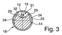
第1の軸受けポイント16および第2の軸受けポイント17はそれぞれ、周囲面18を半径方向に囲むレースウェイ25によって囲まれる。このようにして、バランスシャフト11を、上記の軸受の配置を使用して、そのようなレースウェイ25と共にエンジンブロックに挿入することができ、ここでレースウェイ25は、滑り軸受、特にころ軸受と、転がり軸受の両方と共に使用することができる。あるいは、レースウェイ25は、完全な転がり軸受の内輪部であってもよく、バランスシャフト11を、少なくとも1つの転がり軸受が固定された状態でエンジンブロックに挿入してもよい。同時に、レースウェイ25と軸受けポイント16、17との間で形成される凹部31によるこの配置によって、軸受けポイント16、17を軽量化してもよい。たとえば、図3に示すように、凹部31は、コップ状または皿状に形成してもよい。この実施形態は、180°超の外周角を有する軸受けポイント16、17を備えるのが好ましい。180°の外周角の場合は、回転軸27に位置する平面を備える。あるいは、そのような平面は、回転軸27の上方または下方にあってもよい。180°未満の外周角の場合は、本体の一部が、回転軸まで、あるいは、回転軸を越えて延伸する場合、凹部31は屋根形であってもよい。
The
バランスシャフト11を設計するためのさらなる可能性に関して、国際公開第2007/121861(A1)号パンフレットの開示内容は、参照によって本明細書の一部をなす。本発明では、バランスシャフト11および本体の実施形態を提供してもよい。
With regard to further possibilities for designing the
図1〜図3による本発明によるバランスシャフト11は、バランスシャフト11でレースウェイ25を組み立てる際に、断面図である図4と、図1によるバランスシャフトの大幅に簡略化した概略縦断面図である図5とに示すように、レースウェイ25を受け入れて位置決めするために、軸受けポイント16、17に凹んだ受入領域33を含む。この凹んだ受入領域33は、軸受けポイント16、17の周囲面18に形成される。凹んだ受入領域33は、軸方向に見た場合、周囲面18の一部分によって、周囲面18で区切られるか、または、周囲面18に隣接する。半径方向で見ると、軸受けポイント16、17の周囲面18は、周囲の断面が縮小することによって形成されるリバースドロー成形面34を含み、バランスシャフト11の本体14にレースウェイ25を取り付けることを可能にし、図4に示すように、軸受けポイント16、17の凹んだ受入領域33にレースウェイ25を配置する。
The
凹んだ受入領域33は、半径方向に向いている接触面36を含み、周囲面18に対して凹んでいるか、または、小さな直径を有する。このようにして、軸方向側面37が形成されることにより、凹んだ受入領域33は、溝状、U字状または皿状などとなる。接触面36は、周囲面18に対して凹んでおり、これにより受入領域33に配置したレースウェイ25は、周囲面18に対して滑走面38によって高くなる。このようにして、レースウェイ25は、軸方向の受入領域33に正しく配置される。半径方向かつ周囲方向に見て、軸受けポイントの外周角およびリバースドロー成形面34の大きさに従って、レースウェイ25と受入領域33との間の係合位置を確認することが可能である。
The recessed receiving
バランスシャフト11の本体14にレースウェイ25を挿入するために、レースウェイ25は、挿入前に硬化処置によって前処理するのが好ましいが、レースウェイ25の外側の縁部領域、特に軸方向側面46および内側周囲の隣接する縁部領域は、処理しないか、あるいは、未処理の状態にして、溶接性を確実にする。硬化処置による前処理の後に、レースウェイ25は、バランスシャフト11の本体14に取り付けられ、受入領域33に対して配置される。レースウェイ25は、受入領域33に配置されるが、特に、非ポジティブおよび/またはポジティブな嵌合をもたらすように押し込まれるのが好ましい。次いで、レースウェイ25と受入領域33との間の接着接合が形成され、特にレーザ溶接法が選択される。バランスシャフト11はポイント間で固定され、これにより、軸受の座部の円筒研削および円筒仕上げなどのさらなる作業工程を実施することができる。
In order to insert the
図6aは、図5のAによって表す受入領域33の角領域の概略拡大詳細図を示す。この第1の代替実施形態では、接触面36は、環状であり、側面37に支持され、これにより、周囲の肩部42は形成される。受入領域33の左右に形成される2つの肩部42の間にさらなる凹部43を備え、これにより、レースウェイ25は、半径方向の外側の縁部領域のみによって受入領域33の肩部42に支持される。レースウェイ25の受入領域33に圧入部を挿入した後に、レースウェイ25の軸方向端面46と、受入領域33の側面37との間に圧入部を形成することにより、レースウェイ25は、少なくとも受入領域33に予め固定される。側面37と端面46との間で形成されるギャップは、好ましくは少なくとも複数の部分にわたる溶接シーム48によって密閉されてもよく、これにより、レースウェイ25が本体14に密着して接合される。レーザ溶接を実施するのが好ましい。
6a shows a schematic enlarged detail view of the corner area of the receiving
受入領域33の代替実施形態では、より詳細には示さないが、側面37は放射面に対して外側に傾斜する。このようにして、側面37と軸方向端面46との間に拡大した開口部ギャップを備え、溶接シーム48を配置する。
In an alternative embodiment of the receiving
図6bに示すように、受入領域33の接触面36は、肩部42の角領域に逃げ溝部39を備えるように設計してもよい。その他の点に関しては、上記の実施形態を適用する。
As shown in FIG. 6 b, the
図7aは、図5によるバランスシャフトの代替実施形態の概略断面図である。図7aによるこの実施形態は、受入領域がただ1つの接触面36によって形成されるという点において異なる。このようにして、レースウェイ25は、この1つの接触面36により、バランスシャフトに対して軸方向の定義した位置に配置される。
FIG. 7a is a schematic cross-sectional view of an alternative embodiment of the balance shaft according to FIG. This embodiment according to FIG. 7 a differs in that the receiving area is formed by a
図7aの詳細Xは、図6a、6bに対応しており、したがって、ここで参照することができる。レースウェイ25の反対の軸方向端面46は、受入領域33に対して自由であり、接触面36の上方に高くなる。図7bは、図7aの詳細Yの概略拡大図を示す。この実施形態では、軸方向端面46と受入領域33の接触面36との間の遷移領域に、溶接接合、ハンダ付け接合または接着接合を用いることができる。さらにまた、接触面36は、軸方向端面46のレースウェイ25まで延伸するのみであり、これにより、レースウェイ25と本体14との間の溶接シームを形成するための接近性が改善可能となる。受入領域33に軸方向側面37を1つのみ配置することは、使用目的によっては十分となりうる。
Detail X in FIG. 7a corresponds to FIGS. 6a, 6b and can therefore be referred to here. The opposite
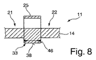
図8は、バランスシャフト11の代替実施形態を縦断面で示す。この実施形態で、バランスシャフト11の受入領域33は、本体14に対して明確に選択されるか、あるいは、半径方向に外側にずれて配置される。受入領域33の接触面36は、レースウェイ25の幅に従って形成されるのが好ましく、これにより接触領域を完全に支持することが可能となる。実施例として示す溶接接合またはハンダ接合は、レースウェイ25の軸方向端面46に接触してもよい。この設計により、必要であれば、バランスシャフト全体の材料をさらに減少することが可能となる。また、この接触面36は、受入領域33のレースウェイ25の幅より大きくても、小さくてもよい。
FIG. 8 shows an alternative embodiment of the
図9は、バランスシャフト11の代替実施形態を縦断面で示す。この実施形態では、本体14または軸受けポイント16、17に対してレースウェイ25を配置するために、非ポジティブな接合および/またはポジティブな接合が提供される。上に示した溶接またはハンダ付けによる接着接合の代わりに、図10aおよび10bの拡大図に示すように、この実施形態では、レースウェイ25は圧締またはコーキングによって固定される。このようにして、受入領域33および受入領域33に支持される周囲面18は互いに適合される。この実施形態では、接触面36は、側面37に直接支持されないが、逃げ溝部39によって分離する。たとえば、接触面36は軸方向に連続している。あるいは、独立した接触部のみを備えていることもある。レースウェイ25は、第1の実施形態(図10aおよび10b)に従って、少なくとも、レースウェイ25の滑走面38に向かってわずかに傾斜する軸方向端面46を含む。圧締またはコーキングのために、受入領域33に対してレースウェイ25を配置した後に、縁部領域51およびその隣接部に切込み部52が形成され、これによって材料圧縮を実現し、これにより、受入領域33の側面37は、非ポジティブ嵌合およびポジティブ嵌合により、レースウェイ25の傾斜する軸方向端面46に支持されて係合し、このようにして、受入領域33にレースウェイ25を固定する。
FIG. 9 shows an alternative embodiment of the
図10cおよび図10dは、レースウェイ25の端面46の代替実施形態に関する概略詳細図を示す。この代替実施形態では、端面46は、たとえば単段状の肩部47を含む。この肩部47は、たとえば、レースウェイ25の厚さの4分の1、3分の1または半分に延伸する。縁部領域51がコーキングされると、材料圧縮により、受入領域33に対するレースウェイ25の非ポジティブな嵌合および/またはポジティブな嵌合が実現される。この肩部47は、効果に関しては傾斜した端面46と同じである。また、肩部47に代わる手段として、多段状の肩部を形成してもよい。また、側面に、さまざまな輪郭部を個別または互いに組み合わせて備えてもよく、これは、縁部領域51の圧締またはコーキングの後に縁部領域51に固定されること、あるいは、この輪郭部が受入領域33の縁部領域を後方から係合することを意味する。さらに、輪郭部により形成される側面は、半径方向かつ周囲方向に凸部または凹部を含んでもよく、これにより、さらに半径方向に固定される。
FIGS. 10 c and 10 d show schematic details for an alternative embodiment of the
図11は、バランスシャフト11のさらなる代替実施形態の縦方向断面図を示す。この実施形態では、レースウェイ25は、受入領域33に対してフランジによって固定される。図11による詳細Cは図12aおよび図12bにさらに詳細に示し、図12aは第1の製造工程を示し、図12bは軸受けポイント16、17にレースウェイ25を固定するための完全なフランジを示す。フランジを作製するために、周囲のビード部51が、受入領域33に支持される周囲面18の縁部領域に備えられる。このビード部51により、その後のフランジ成形工程のために材料が圧縮される。受入領域33にレースウェイ25を効果的に確実に固定するために、レースウェイ25は、滑走面38に対して傾斜する端面46を含む。レースウェイ25の位置決めおよび可能であれば圧締後、ビード部51は端面46に向かって打ち込まれ、これにより、端面46は、受入領域33の所定の位置にフランジを付けたビード部51によって形成される一種の逃げ溝部によって保持固定される。
FIG. 11 shows a longitudinal sectional view of a further alternative embodiment of the
または、図11、図12aおよび図12bに示す実施形態に対して、受入領域33は、回転加工により逃げ溝部を形成した側面37を有してもよく、これにより、反対側にはフランジ処理が1回しか必要でない。
Alternatively, for the embodiment shown in FIGS. 11, 12 a and 12 b, the receiving
図13a〜図13cにバランスシャフト11のさらなる代替実施形態を示す。このバランスシャフト11により、本体14は軸受けポイント16、17の領域に周囲面18を含み、周囲面は180°未満の角度を成し、その周囲面18は遠心力が作用する領域にある。補強輪郭部54は、示した実施形態により屋根形であり、特に2つのリバースドロー成形面34によって形成され、周囲面18の2つの外側端部の間に延伸する。周囲面18と共に、この補強輪郭部52は、その外側に回転軸27がある断面領域を形成するのが好ましい。そのような実施形態は、鍛造技術を使用することにより、そのようなバランスシャフト11を容易に作製できるという利点をもたらす。あるいは、補強輪郭部は、周囲面と共に断面領域を形成してもよく、回転軸は断面領域内にある。補強輪郭部54と、アンバランスウェイト部21、22、23、24の周囲面30または周囲面18との間に、片側または両側にさらなるリバースドロー成形面34’を隣接して備えてもよい。図13a〜図13cのこの実施形態では、レースウェイ25は、図10cおよび図10dによる上記の実施形態に基づいて周囲面18に締結される。上記の他の実施形態および以下に記載される実施形態に従ってレースウェイ25を締結して形成してもよい。
A further alternative embodiment of the
図14aおよび図14bは、バランスシャフト11のさらなる代替実施形態を側面図および斜視図で示す。この実施形態では、レースウェイ25のジオメトリは、支持部61または締結部のさらなる配置によって変わる。支持部61は、周囲全体に延伸するレースウェイ25に向かって片側または両側で軸方向に延伸してもよく、支持部は、半径方向に少なくとも一部延伸するが、周囲全体に形成されない。支持部61は、リバースドロー成形面34が後に続くまで、受入領域33がその上に延伸する周囲領域に、半径方向かつ周囲方向に延伸するのが好ましい。支持部61の設計により、拡大した締結領域を形成して、受入領域33にレースウェイ25を固定することができる。たとえば、半径方向の端面61に沿って、本体14にさらに締結可能であってもよい。さらに、このようにして、レースウェイ25の滑走面38の外側に締結領域が形成され、その設計は、レースウェイ25の滑走面38から独立しているという利点をもたらすことができる。受入領域33に対するレースウェイ25の配置は、上に示した実施形態を含んでもよい。図13aおよび図13bに示す実施形態は、図7aおよび図7bに示す実施形態と、配置および成形に関して記載した代替実施形態とに基本的に対応している。
14a and 14b show a further alternative embodiment of the
図14cおよび図14dは、図14aおよび図14bに対する代替実施形態の斜視図を示す。図14cおよび図14dに示す実施形態では、支持部61は周囲全体に延伸するレースウェイ25の両側に備えられる。これらの実施形態では、溶接シームは、たとえば、半径方向の端面62に沿って取り付け可能となる。あるいは、またはさらに、軸方向端面63に沿って軸方向に延伸する溶接シームを代わりに備えてもよい。さらにまた、広い領域にわたってレースウェイ25が接触するために、接着接合が可能であってもよい。あるいは、またはさらに、たとえば図に示す点64によって表されるように、スポット溶接してもよい。また、上記の締結可能性を多用途に組み合わせてもよい。
Figures 14c and 14d show perspective views of an alternative embodiment to Figures 14a and 14b. In the embodiment shown in FIGS. 14c and 14d, the
図14dは、受入領域33にレースウェイ25を固定するためのさらなる代替実施形態を示し、端面62にフランジを付け、これにより、受入領域33に対してレースウェイ25の半径方向および/または軸方向に固定する。フランジ成形に加えて、溶接シーム、接着接合および/またはスポット溶接接合を実施してもよい。
FIG. 14 d shows a further alternative embodiment for securing the
図14eは、バランスシャフト11にレースウェイ25を締結するさらなる代替設計の、簡略化した概略図を示す。この実施形態では、タブとして形成される支持部または締結部61は、レースウェイ25に備えられ、点溶接、リベット、ネジなどによってバランスシャフト11の本体14に固定される。
FIG. 14 e shows a simplified schematic diagram of a further alternative design for fastening the
図15a〜図15dは、実施例としてレースウェイ25のさまざまな実施形態を示す。固定幅のレースウェイ25の代わりに、アンバランスウェイト部21、22、23、24の領域および反対側の領域または効果的な遠心力の反対方向の領域に固定幅で形成されるレースウェイ25は、先端部71まで延伸する縮小したウェブ部を有し、これは例えば図15aに従って備えられてもよい。この実施形態では、レースウェイ25の幅は、受入領域33の外側にのみ減少する。レースウェイ25の狭い部分と広い部分との間に遷移領域を備えられた図15aに示す輪郭部の代わりに、漸減領域は、図に示す漸減の代わりに、先端部71まで連続的にも非連続的にも漸減してもよい。図15bは、図15aと比較したレースウェイ25の代替実施形態を示す。この場合、たとえば受入領域33の外側に2つのウェブ状のレースウェイ部を形成する。
15a-15d show various embodiments of the
図15cは、レースウェイ25のさらなる代替実施形態を示す。この場合、レースウェイの幅は、受入領域33内のアンバランスの最も少ない点から先端部71まで連続的に漸減する。また、この漸減は不連続でも非対称でもよい。たとえば、図15dに代替実施形態を示しているが、レースウェイ25の幅の片側のみが減少し、連続でも不連続でもよい。
FIG. 15 c shows a further alternative embodiment of the
図15eは、図14aおよび14bに対する代替実施形態を示し、受入領域33の外側に配置されるレースウェイ25の滑走面38は、固定幅の代わりに、先端71に向かって幅が減少するように形成される。受入領域33の外側のレースウェイ15a〜15dの上記の代替実施形態は、両側に延伸する支持部61と、片側のみに延伸する支持部61とを図15eによる実施形態に備えてもよい。
FIG. 15e shows an alternative embodiment to FIGS. 14a and 14b, in which the
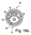
図16aは、バランスシャフト11の代替実施形態の、図1と比較した詳細斜視図を示す。このバランスシャフト11は、図1のバランスシャフト11の基本構造に対応しており、アンバランスウェイト部24が接続する端部13を含む。軸受けポイント16は、レースウェイ25の代わりに転がり軸受76を受け入れる。さらなるアンバランスウェイト部23および/または接続部19が接続される。図1〜図13cによる上記の実施形態に記載したように、転がり軸受76は、レースウェイ25の締結と同じように、機能に関してレースウェイ25と同じと考えられる内輪部を介して締結される。
FIG. 16 a shows a detailed perspective view of an alternative embodiment of the
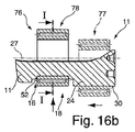
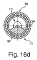
図16bは、軸受けポイント16の受入領域33に転がり軸受76を配置して固定するための、転がり軸受76の第1の組み立て位置77および第2の組み立て位置78を示す概略部分断面図である。図16cは第1の組み立て位置77の概略断面図を示し、図16dは軸受けポイント16と第2の組み立て位置78の断面図を示す。
FIG. 16 b is a schematic partial sectional view showing a
この実施形態では、たとえば、軸受けポイント16の周囲面18が延伸する外周角は、アンバランスウェイト部24の周囲面30の外周角より大きい。この実施形態では、アンバランスウェイト部24の周囲面30は、端部13の端面までまっすぐ延伸する。あるいは、逆に周囲面30の外周角は周囲面18の外周角より大きくてもよく、同じであってもよい。図16cに示すように、端部13の領域のリバースドロー成形した直径は、レースウェイ25の内径や、転がり軸受76の内輪部より小さい。図16cにも示すように、軸受けポイント16の周囲面18およびリバースドロー成形面34の設計にも同じことが当てはまる。転がり軸受76またはレースウェイ25は、最初に端部13を越えて第1の組み立て位置77に移動してもよい。軸受けポイント16まで軸方向に、転がり軸受76またはレースウェイ25をさらに位置決めしてもよい。レースウェイ25または転がり軸受76は、垂直方向の位置に配置され、これにより、第2の組み立て位置78を用いる。上記の実施形態によれば、受入領域33のレースウェイ25または転がり軸受76のその後の締結を実現する。図16dは、図16bの線I−Iに沿った断面図であり、ここでも組み立て位置78を示す。
In this embodiment, for example, the outer peripheral angle at which the
あるいは、たとえば図13cに示すように、さらなるリバースドロー成形面34’を、図16aによるバランスシャフトのこのような実施形態に備えてもよい。軸受けポイント16にも同じことが当てはまる。
Alternatively, an additional reverse draw forming surface 34 'may be provided in such an embodiment of the balance shaft according to Fig. 16a, for example as shown in Fig. 13c. The same applies to the
また、アンバランスウェイト部が軸受けポイント16に接続され、次いで、接続点19の代わりにさらなる軸受けポイントが形成される一実施形態でも、リバースドロー成形した直径を維持することができる。また、上に示す特徴および代替手段は、そのような実施形態にも適用される。
Also, in an embodiment in which the unbalance weight is connected to the
受入領域ならびに、受入領域33に非ポジティブ嵌合および/またはポジティブ嵌合および/または密着嵌合したレースウェイ25の実施例として記載した実施形態は、すべての実施形態に備えてもよく、国際公開第2007/121861(A1)号パンフレットに記載のバランスシャフトに備えてもよい。
The embodiment described as an example of the receiving area and the
Claims (15)
前記軸受けポイント(16、17)は、
前記軸受けポイント(16、17)の周囲に一部のみ延伸する半径方向の周囲面(18)を含み、これにより、バランスシャフト(11)の回転から生じる遠心力が、前記軸受けポイント(16、17)の周囲に一部延伸する前記周囲面(18)によって形成される前記軸受けポイント(16、17)の領域にあり、
前記軸受けポイント(16、17)の部分的に形成された周囲面(18)を囲み、非ポジティブ接合および/またはポジティブ接合および/または密着接合によって前記軸受けポイント(16、17)に接続されるレースウェイ(25)を含む、単気筒エンジンまたは多気筒エンジン用のバランスシャフトであって、
前記軸受けポイント(16、17)の前記周囲面(18)は、前記レースウェイ(25)を受けるための受入領域(33)と、非ポジティブ嵌合および/またはポジティブ嵌合および/または密着嵌合によって前記受入領域(33)の少なくとも軸側面(37)に接続される、前記レースウェイ(25)の少なくとも軸方向に外側の縁部領域または少なくとも環状の領域とを有し、または、前記レースウェイ(25)は、その滑走面(38)に、および、該滑走面に隣接して軸方向に支持部(61)を有し、該支持部(61)は、半径方向に少なくとも一部延伸するが周囲全体に延伸せず、前記受入領域(33)または本体(14)に接続されることを特徴とする、バランスシャフト。 At least one unbalanced weight part (21, 22; 23, 24) and at least one bearing point (16, 17) associated with said at least one unbalanced weight part (21, 22; 23, 24); Including
The bearing points (16, 17) are
A radial peripheral surface (18) extending only partially around the bearing point (16, 17) is included so that the centrifugal force resulting from the rotation of the balance shaft (11) is applied to the bearing point (16, 17). ) In the region of the bearing points (16, 17) formed by the peripheral surface (18) partially extending around
A race surrounding a partially formed peripheral surface (18) of the bearing point (16, 17) and connected to the bearing point (16, 17) by non-positive and / or positive and / or tight bonding A balance shaft for a single cylinder engine or a multi-cylinder engine, including the way (25),
The peripheral surface (18) of the bearing point (16, 17) has a receiving area (33) for receiving the raceway (25) and a non-positive and / or positive and / or tight fit And at least an axially outer edge region or at least an annular region of the raceway (25) connected to at least the axial side surface (37) of the receiving region (33), or the raceway (25) has a support (61) in the axial direction on and adjacent to the sliding surface (38), the support (61) extending at least partially in the radial direction. There does not extend in the entire circumference, the or receiving region (33) is characterized in that it is connected to the body (14), balance shaft.
前記受入領域(33)が、前記受入領域(33)の幅に沿って少なくとも一部に延伸する少なくとも1つの環状の接触面(36)を含む
ことを特徴とする、請求項1に記載のバランスシャフト。 The receiving area (33) is recessed,
The balance according to claim 1, characterized in that the receiving area (33) comprises at least one annular contact surface (36) extending at least partly along the width of the receiving area (33). shaft.
Applications Claiming Priority (5)
| Application Number | Priority Date | Filing Date | Title |
|---|---|---|---|
| DE102009035684A DE102009035684A1 (en) | 2009-07-30 | 2009-07-30 | Balance shaft for e.g. multicylinder engine, has raceway with axial outer edge region or annular region connected with contact surface of support region in force-fit and/or form-fit and/or material-fit manner |
| DE102009035684.3 | 2009-07-30 | ||
| DE102009040813 | 2009-09-10 | ||
| DE102009040813.4 | 2009-09-10 | ||
| PCT/EP2010/004408 WO2011012239A2 (en) | 2009-07-30 | 2010-07-20 | Countershaft |
Publications (3)
| Publication Number | Publication Date |
|---|---|
| JP2013500442A JP2013500442A (en) | 2013-01-07 |
| JP2013500442A5 JP2013500442A5 (en) | 2013-06-20 |
| JP5518190B2 true JP5518190B2 (en) | 2014-06-11 |
Family
ID=43529746
Family Applications (1)
| Application Number | Title | Priority Date | Filing Date |
|---|---|---|---|
| JP2012521999A Active JP5518190B2 (en) | 2009-07-30 | 2010-07-20 | Balance shaft |
Country Status (5)
| Country | Link |
|---|---|
| US (1) | US8939123B2 (en) |
| EP (1) | EP2459899B1 (en) |
| JP (1) | JP5518190B2 (en) |
| CN (1) | CN102597568B (en) |
| WO (1) | WO2011012239A2 (en) |
Families Citing this family (19)
| Publication number | Priority date | Publication date | Assignee | Title |
|---|---|---|---|---|
| JP5782807B2 (en) | 2011-04-22 | 2015-09-24 | 株式会社ジェイテクト | Balancer shaft device |
| DE102011087535A1 (en) * | 2011-12-01 | 2013-06-06 | Mahle International Gmbh | balancer shaft |
| DE102014209869B3 (en) * | 2014-05-23 | 2015-07-23 | Hirschvogel Umformtechnik Gmbh | Method for producing a shaft |
| DE102014214004B4 (en) * | 2014-07-18 | 2019-10-10 | Aktiebolaget Skf | Radial bearing, especially for an imbalance shaft |
| DE102015202313A1 (en) * | 2015-02-10 | 2016-08-11 | Bayerische Motoren Werke Aktiengesellschaft | balancer shaft |
| CN106884931B (en) * | 2015-12-16 | 2019-02-26 | 北汽福田汽车股份有限公司 | A kind of balance shaft module |
| DE102016210480B4 (en) | 2016-06-30 | 2022-03-24 | Bayerische Motoren Werke Aktiengesellschaft | Method of manufacturing a mass balance shaft and mass balance shaft produced therefrom |
| KR101868437B1 (en) * | 2016-11-10 | 2018-06-20 | (주)동보 | Balance shaft |
| DE102018105186B4 (en) * | 2018-03-07 | 2023-09-28 | Schaeffler Technologies AG & Co. KG | Balance shaft |
| US10823255B2 (en) | 2018-03-27 | 2020-11-03 | Daniel CADALSO | Balancing system for a rotating member |
| EP3587857B1 (en) | 2018-06-21 | 2022-04-06 | Hirschvogel Umformtechnik GmbH | Balance shaft and method for manufacturing same |
| DE102018115429B4 (en) | 2018-06-27 | 2021-11-11 | Schaeffler Technologies AG & Co. KG | Unbalance shaft |
| DE102019101322B4 (en) * | 2018-08-30 | 2021-08-05 | Schaeffler Technologies AG & Co. KG | Balance shaft |
| DE102019101321A1 (en) * | 2018-08-30 | 2020-03-05 | Schaeffler Technologies AG & Co. KG | Balance shaft |
| DE102019101319B4 (en) | 2018-11-16 | 2021-11-18 | Schaeffler Technologies AG & Co. KG | Balance shaft |
| DE102019101318A1 (en) * | 2018-08-30 | 2020-03-05 | Schaeffler Technologies AG & Co. KG | Balance shaft |
| WO2020043241A1 (en) | 2018-08-30 | 2020-03-05 | Schaeffler Technologies AG & Co. KG | Balance shaft |
| DE102019101320A1 (en) * | 2018-08-30 | 2020-03-05 | Schaeffler Technologies AG & Co. KG | Balance shaft |
| US11754145B2 (en) * | 2018-11-16 | 2023-09-12 | Schaeffler Technologies AG & Co. KG | Balance shaft assembly |
Family Cites Families (48)
| Publication number | Priority date | Publication date | Assignee | Title |
|---|---|---|---|---|
| US1749807A (en) | 1926-04-22 | 1930-03-11 | Ford Motor Co | Crank shaft |
| US2838957A (en) | 1954-06-14 | 1958-06-17 | Gen Motors Corp | Engine balancing means |
| GB1313491A (en) | 1969-04-25 | 1973-04-11 | Perkins Engines Ltd | Internal combustion engine crankshafts |
| US3748925A (en) | 1970-04-09 | 1973-07-31 | Perkins Engines Ltd | Crankshaft balance weights and method of assembly |
| JPS5110204A (en) | 1974-07-16 | 1976-01-27 | Mitsubishi Motors Corp | Enjinno baransasochi |
| JPS54139936U (en) | 1978-03-20 | 1979-09-28 | ||
| JPS6038544B2 (en) | 1979-10-17 | 1985-09-02 | 株式会社デンソー | Engine speed control method |
| JPS57195944A (en) | 1981-05-29 | 1982-12-01 | Yamaha Motor Co Ltd | Balancer device of internal combustion engine |
| JPS5839830A (en) | 1981-08-31 | 1983-03-08 | Fuji Heavy Ind Ltd | Blancer for three-cylinder engine |
| FR2619881B1 (en) * | 1987-08-31 | 1990-01-19 | Peugeot | BALANCING SHAFT FOR A RECIPROCATING PISTON ENGINE |
| US5237892A (en) | 1992-07-28 | 1993-08-24 | Tecumseh Products Company | Reduced material crankshaft fabrication |
| JPH07217638A (en) | 1994-02-07 | 1995-08-15 | Nissan Motor Co Ltd | Crankshaft structure for internal combustion engine |
| JPH09151993A (en) | 1995-11-28 | 1997-06-10 | Honda Motor Co Ltd | Bearing part lubrication structure of balancer shaft |
| US5791309A (en) | 1996-02-06 | 1998-08-11 | Honda Giken Kogyo Kabushiki Kaisha | Balancer shaft supporting structure in engine |
| US6237442B1 (en) | 1996-07-09 | 2001-05-29 | Simpson Industries, Inc. | High value static unbalance-type balance shafts |
| EP0753678B1 (en) | 1996-07-17 | 2003-04-23 | Maag Pump Systems Textron AG | Sliding-contact bearing for a shaft |
| JPH11101311A (en) * | 1997-09-29 | 1999-04-13 | Nissan Diesel Motor Co Ltd | Balancer device of internal combustion engine |
| DE19835145A1 (en) | 1998-08-04 | 2000-02-10 | Daimler Chrysler Ag | Tubular low cost automotive crankshaft mass balancing shaft is shrouded to reduce air noise or foaming of oil at high engine speeds |
| CA2316152C (en) | 1999-09-03 | 2004-10-05 | Honda Giken Kogyo Kabushiki Kaisha | Balance shaft for engine balancing systems |
| JP3643506B2 (en) | 1999-09-03 | 2005-04-27 | 本田技研工業株式会社 | Housing for balance shaft |
| JP3685693B2 (en) | 1999-09-03 | 2005-08-24 | 本田技研工業株式会社 | Balance axis |
| DE50007637D1 (en) | 1999-10-12 | 2004-10-07 | Magna Steyr Powertrain Ag & Co | DEVICE FOR COMPENSATING THE MASS FORCES IN LIFTING PISTON MACHINES |
| AT5222U1 (en) | 1999-10-19 | 2002-04-25 | Steyr Daimler Puch Ag | COMPENSATING SHAFT UNIT FOR PISTON PISTON |
| US6581495B2 (en) | 2000-01-26 | 2003-06-24 | International Engine Intellectual Property Company, Llc | Balancer shaft |
| DE10006690C1 (en) | 2000-02-15 | 2001-06-28 | Ktm Sportmotorcycle Ag Mattigh | Starter for motorcycle two-cylinder V-configuration internal combustion engine has starter motor and gearbox mounted in V-shaped intermediate space between cylinders above crankshaft |
| US6405702B2 (en) | 2000-03-24 | 2002-06-18 | Yamaha Hatsudoki Kabushiki Kaisha | Balancer shaft for internal combustion engine |
| AT4395U1 (en) | 2000-04-06 | 2001-06-25 | Avl List Gmbh | COMPENSATING SHAFT FOR AN INTERNAL COMBUSTION ENGINE |
| DE10032095B4 (en) | 2000-07-01 | 2005-06-23 | Dr.Ing.H.C. F. Porsche Ag | Crank drive for an internal combustion engine |
| GB0106852D0 (en) | 2001-03-20 | 2001-05-09 | Perkins Engines Co Ltd | Balance shaft assembly |
| FR2823279B1 (en) | 2001-04-09 | 2005-11-11 | Renault Sas | BALANCING SHAFT COMPRISING CYLINDRICAL BALANCING BLOCKS PRODUCED BY OVERMOLDING |
| JP3849469B2 (en) | 2001-07-23 | 2006-11-22 | 日産自動車株式会社 | Toroidal continuously variable transmission |
| DE10257562A1 (en) | 2002-12-10 | 2004-07-01 | Adam Opel Ag | Mass compensator for a vehicle combustion engine, has compensating shaft below crankshaft with through screws mounting bearing block onto engine block |
| JP4239710B2 (en) | 2003-06-26 | 2009-03-18 | トヨタ自動車株式会社 | Balance shaft |
| DE10347348A1 (en) | 2003-10-11 | 2005-05-12 | Daimler Chrysler Ag | Balance shaft for IC engines comprises hollow extruded tube, one section of which forms counterweight, bearing seatings and clearances being cut from extrusion |
| DE102004014014B4 (en) | 2004-03-23 | 2006-06-22 | Daimlerchrysler Ag | Balancing shaft for a multi-cylinder in-line engine |
| JP2006002852A (en) | 2004-06-17 | 2006-01-05 | Hitachi Ltd | Engine balancer device |
| US20050284254A1 (en) * | 2004-06-25 | 2005-12-29 | Eagle-Picher Industries, Inc. | Balance shaft |
| AT8014U1 (en) | 2004-11-08 | 2005-12-15 | Magna Drivetrain Ag & Co Kg | BALANCING UNIT AND YOUR STORAGE |
| DE202006020559U1 (en) | 2005-10-13 | 2008-12-18 | Schaeffler Kg | radial bearing |
| DE102007009800A1 (en) * | 2006-04-18 | 2007-10-25 | Herzog Intertec Gmbh | balancer shaft |
| DE102007027990A1 (en) * | 2007-06-14 | 2008-12-18 | Herzog Intertec Gmbh | balancer shaft |
| DE202007018991U1 (en) * | 2007-06-14 | 2009-12-31 | Herzog Intertec Gmbh | balancer shaft |
| US7647910B2 (en) * | 2007-08-17 | 2010-01-19 | Schaeffler Kg | Compensating shaft for an engine |
| US7617810B1 (en) | 2007-12-03 | 2009-11-17 | Brunswick Corporation | Counterweight shaft construction which reduces lubricant aeration |
| DE102008009557A1 (en) * | 2008-02-16 | 2009-08-20 | Schaeffler Kg | Balance shaft for a multi-cylinder engine |
| JP2009210134A (en) | 2008-02-29 | 2009-09-17 | Daikin Ind Ltd | Grip tool, outdoor unit of air conditioner comprising handle tool, and air conditioner using outdoor unit |
| JP2010270783A (en) * | 2009-05-19 | 2010-12-02 | Jtekt Corp | Balancer-shaft-supporting bearing unit |
| DE102009035112A1 (en) * | 2009-07-29 | 2011-02-03 | Schaeffler Technologies Gmbh & Co. Kg | unbalanced shaft |
-
2010
- 2010-07-20 CN CN201080031867.3A patent/CN102597568B/en active Active
- 2010-07-20 US US13/387,881 patent/US8939123B2/en active Active
- 2010-07-20 JP JP2012521999A patent/JP5518190B2/en active Active
- 2010-07-20 EP EP10795919.9A patent/EP2459899B1/en active Active
- 2010-07-20 WO PCT/EP2010/004408 patent/WO2011012239A2/en active Application Filing
Also Published As
| Publication number | Publication date |
|---|---|
| US8939123B2 (en) | 2015-01-27 |
| EP2459899B1 (en) | 2017-02-22 |
| US20120125281A1 (en) | 2012-05-24 |
| CN102597568A (en) | 2012-07-18 |
| CN102597568B (en) | 2014-09-03 |
| EP2459899A2 (en) | 2012-06-06 |
| WO2011012239A3 (en) | 2011-06-23 |
| WO2011012239A2 (en) | 2011-02-03 |
| JP2013500442A (en) | 2013-01-07 |
Similar Documents
| Publication | Publication Date | Title |
|---|---|---|
| JP5518190B2 (en) | Balance shaft | |
| CA2898794C (en) | Joint-site design comprising a hub and a shaft or a gear being friction welded | |
| US9624976B2 (en) | Method of manufacturing corrugated cage and corrugated cage | |
| JP5092913B2 (en) | Universal joint yoke and universal joint | |
| US20150316092A1 (en) | Assembled crankshaft and method for producing an assembled crankshaft | |
| EP2647882B1 (en) | Torque transmitting assembly and method of producing | |
| JP6911206B2 (en) | Compressor and its manufacturing method | |
| US8168285B2 (en) | Joined component, in particular a pilot boss for a force transfer device, method for manufacture of a continuous material connection and a force transfer device | |
| US9415633B2 (en) | Assembly comprising a radially intermediate joint and corresponding method of joining two components | |
| JP6049935B1 (en) | Joint yoke for universal joint and universal joint | |
| CA2810870A1 (en) | Torque transmitting assembly and method of producing | |
| KR20210088561A (en) | balance shaft | |
| KR20170043045A (en) | Wheel bearing and manufacturing method of the same | |
| CN107532704A (en) | Differential casing | |
| JP2010242917A (en) | Split type rolling bearing and method of manufacturing the same | |
| US20120151907A1 (en) | Flanged impeller hub | |
| JP4117741B2 (en) | Camshaft end piece and camshaft | |
| JP2008272818A (en) | Friction welding structure and axle-housing | |
| JP2021165130A (en) | Hub unit bearing and vehicle | |
| KR20130036485A (en) | Hub for damper pulley | |
| WO2017038630A1 (en) | Deep groove ball bearing | |
| JP5051068B2 (en) | Assembled crankshaft and manufacturing method thereof | |
| JP2004245388A (en) | Bearing structure | |
| JP2005226812A (en) | Constant velocity universal joint | |
| JP4306645B2 (en) | Manufacturing method of wheel supporting hub unit |
Legal Events
| Date | Code | Title | Description |
|---|---|---|---|
| A521 | Request for written amendment filed |
Free format text: JAPANESE INTERMEDIATE CODE: A523 Effective date: 20130425 |
|
| A621 | Written request for application examination |
Free format text: JAPANESE INTERMEDIATE CODE: A621 Effective date: 20130425 |
|
| A977 | Report on retrieval |
Free format text: JAPANESE INTERMEDIATE CODE: A971007 Effective date: 20140123 |
|
| A131 | Notification of reasons for refusal |
Free format text: JAPANESE INTERMEDIATE CODE: A131 Effective date: 20140204 |
|
| A521 | Request for written amendment filed |
Free format text: JAPANESE INTERMEDIATE CODE: A523 Effective date: 20140210 |
|
| TRDD | Decision of grant or rejection written | ||
| A01 | Written decision to grant a patent or to grant a registration (utility model) |
Free format text: JAPANESE INTERMEDIATE CODE: A01 Effective date: 20140311 |
|
| A61 | First payment of annual fees (during grant procedure) |
Free format text: JAPANESE INTERMEDIATE CODE: A61 Effective date: 20140401 |
|
| R150 | Certificate of patent or registration of utility model |
Ref document number: 5518190 Country of ref document: JP Free format text: JAPANESE INTERMEDIATE CODE: R150 |
|
| R250 | Receipt of annual fees |
Free format text: JAPANESE INTERMEDIATE CODE: R250 |
|
| R250 | Receipt of annual fees |
Free format text: JAPANESE INTERMEDIATE CODE: R250 |
|
| R250 | Receipt of annual fees |
Free format text: JAPANESE INTERMEDIATE CODE: R250 |
|
| R250 | Receipt of annual fees |
Free format text: JAPANESE INTERMEDIATE CODE: R250 |
|
| R250 | Receipt of annual fees |
Free format text: JAPANESE INTERMEDIATE CODE: R250 |
|
| R250 | Receipt of annual fees |
Free format text: JAPANESE INTERMEDIATE CODE: R250 |
|
| R250 | Receipt of annual fees |
Free format text: JAPANESE INTERMEDIATE CODE: R250 |
|
| R250 | Receipt of annual fees |
Free format text: JAPANESE INTERMEDIATE CODE: R250 |