JP5498508B2 - Quick connect prosthetic heart valve and method - Google Patents
Quick connect prosthetic heart valve and method Download PDFInfo
- Publication number
- JP5498508B2 JP5498508B2 JP2011542476A JP2011542476A JP5498508B2 JP 5498508 B2 JP5498508 B2 JP 5498508B2 JP 2011542476 A JP2011542476 A JP 2011542476A JP 2011542476 A JP2011542476 A JP 2011542476A JP 5498508 B2 JP5498508 B2 JP 5498508B2
- Authority
- JP
- Japan
- Prior art keywords
- valve
- stent
- expandable
- balloon
- prosthetic
- Prior art date
- Legal status (The legal status is an assumption and is not a legal conclusion. Google has not performed a legal analysis and makes no representation as to the accuracy of the status listed.)
- Active
Links
- 210000003709 heart valve Anatomy 0.000 title claims description 69
- 238000000034 method Methods 0.000 title description 59
- 238000009958 sewing Methods 0.000 claims description 31
- 230000008878 coupling Effects 0.000 claims description 10
- 238000010168 coupling process Methods 0.000 claims description 10
- 238000005859 coupling reaction Methods 0.000 claims description 10
- 238000002513 implantation Methods 0.000 description 31
- 210000002216 heart Anatomy 0.000 description 27
- 238000001356 surgical procedure Methods 0.000 description 24
- 210000001519 tissue Anatomy 0.000 description 18
- 230000002861 ventricular Effects 0.000 description 15
- 210000001765 aortic valve Anatomy 0.000 description 14
- 239000008280 blood Substances 0.000 description 12
- 210000004369 blood Anatomy 0.000 description 12
- 210000003811 finger Anatomy 0.000 description 12
- 210000004115 mitral valve Anatomy 0.000 description 11
- 230000008901 benefit Effects 0.000 description 9
- 210000005240 left ventricle Anatomy 0.000 description 9
- 210000000709 aorta Anatomy 0.000 description 8
- 238000013459 approach Methods 0.000 description 8
- 210000000591 tricuspid valve Anatomy 0.000 description 8
- 238000004873 anchoring Methods 0.000 description 7
- 230000014759 maintenance of location Effects 0.000 description 7
- 239000002184 metal Substances 0.000 description 7
- 230000008602 contraction Effects 0.000 description 6
- 230000001965 increasing effect Effects 0.000 description 6
- 239000000463 material Substances 0.000 description 6
- 230000000747 cardiac effect Effects 0.000 description 5
- 230000002950 deficient Effects 0.000 description 5
- 239000004744 fabric Substances 0.000 description 5
- 210000002837 heart atrium Anatomy 0.000 description 5
- 230000008569 process Effects 0.000 description 5
- 230000002787 reinforcement Effects 0.000 description 5
- 230000003014 reinforcing effect Effects 0.000 description 5
- 230000017531 blood circulation Effects 0.000 description 4
- 230000004087 circulation Effects 0.000 description 4
- 238000013461 design Methods 0.000 description 4
- 229920000728 polyester Polymers 0.000 description 4
- 210000003102 pulmonary valve Anatomy 0.000 description 4
- 239000010935 stainless steel Substances 0.000 description 4
- 229910001220 stainless steel Inorganic materials 0.000 description 4
- 230000007704 transition Effects 0.000 description 4
- 210000003157 atrial septum Anatomy 0.000 description 3
- 210000003748 coronary sinus Anatomy 0.000 description 3
- 230000006870 function Effects 0.000 description 3
- 210000005246 left atrium Anatomy 0.000 description 3
- 230000007246 mechanism Effects 0.000 description 3
- 210000003205 muscle Anatomy 0.000 description 3
- 210000003540 papillary muscle Anatomy 0.000 description 3
- 239000004033 plastic Substances 0.000 description 3
- 230000008439 repair process Effects 0.000 description 3
- 229920004934 Dacron® Polymers 0.000 description 2
- 208000027418 Wounds and injury Diseases 0.000 description 2
- WYTGDNHDOZPMIW-RCBQFDQVSA-N alstonine Natural products C1=CC2=C3C=CC=CC3=NC2=C2N1C[C@H]1[C@H](C)OC=C(C(=O)OC)[C@H]1C2 WYTGDNHDOZPMIW-RCBQFDQVSA-N 0.000 description 2
- 206010002906 aortic stenosis Diseases 0.000 description 2
- 210000005242 cardiac chamber Anatomy 0.000 description 2
- 230000002612 cardiopulmonary effect Effects 0.000 description 2
- 230000008859 change Effects 0.000 description 2
- 238000005520 cutting process Methods 0.000 description 2
- 229910003460 diamond Inorganic materials 0.000 description 2
- 239000010432 diamond Substances 0.000 description 2
- 239000012530 fluid Substances 0.000 description 2
- 238000004519 manufacturing process Methods 0.000 description 2
- 229910001000 nickel titanium Inorganic materials 0.000 description 2
- HLXZNVUGXRDIFK-UHFFFAOYSA-N nickel titanium Chemical compound [Ti].[Ti].[Ti].[Ti].[Ti].[Ti].[Ti].[Ti].[Ti].[Ti].[Ti].[Ni].[Ni].[Ni].[Ni].[Ni].[Ni].[Ni].[Ni].[Ni].[Ni].[Ni].[Ni].[Ni].[Ni] HLXZNVUGXRDIFK-UHFFFAOYSA-N 0.000 description 2
- 239000005020 polyethylene terephthalate Substances 0.000 description 2
- 238000005086 pumping Methods 0.000 description 2
- 230000001105 regulatory effect Effects 0.000 description 2
- 210000005245 right atrium Anatomy 0.000 description 2
- 210000005241 right ventricle Anatomy 0.000 description 2
- 238000012800 visualization Methods 0.000 description 2
- 208000019901 Anxiety disease Diseases 0.000 description 1
- 208000017667 Chronic Disease Diseases 0.000 description 1
- 102000008186 Collagen Human genes 0.000 description 1
- 108010035532 Collagen Proteins 0.000 description 1
- 206010010904 Convulsion Diseases 0.000 description 1
- 229920004943 Delrin® Polymers 0.000 description 1
- 240000006829 Ficus sundaica Species 0.000 description 1
- 239000004743 Polypropylene Substances 0.000 description 1
- FAPWRFPIFSIZLT-UHFFFAOYSA-M Sodium chloride Chemical compound [Na+].[Cl-] FAPWRFPIFSIZLT-UHFFFAOYSA-M 0.000 description 1
- 241000251539 Vertebrata <Metazoa> Species 0.000 description 1
- 230000001154 acute effect Effects 0.000 description 1
- 239000000853 adhesive Substances 0.000 description 1
- 230000001070 adhesive effect Effects 0.000 description 1
- 230000002411 adverse Effects 0.000 description 1
- 210000003484 anatomy Anatomy 0.000 description 1
- 230000036506 anxiety Effects 0.000 description 1
- 210000001367 artery Anatomy 0.000 description 1
- 230000001746 atrial effect Effects 0.000 description 1
- 230000004323 axial length Effects 0.000 description 1
- 238000010009 beating Methods 0.000 description 1
- 238000005452 bending Methods 0.000 description 1
- 210000004763 bicuspid Anatomy 0.000 description 1
- 230000005540 biological transmission Effects 0.000 description 1
- 230000015572 biosynthetic process Effects 0.000 description 1
- 210000004204 blood vessel Anatomy 0.000 description 1
- 230000036760 body temperature Effects 0.000 description 1
- 230000002308 calcification Effects 0.000 description 1
- 229920001436 collagen Polymers 0.000 description 1
- 230000000295 complement effect Effects 0.000 description 1
- 210000004351 coronary vessel Anatomy 0.000 description 1
- 238000002788 crimping Methods 0.000 description 1
- 238000009792 diffusion process Methods 0.000 description 1
- 238000005516 engineering process Methods 0.000 description 1
- 230000002708 enhancing effect Effects 0.000 description 1
- 239000000835 fiber Substances 0.000 description 1
- 230000003176 fibrotic effect Effects 0.000 description 1
- 238000002594 fluoroscopy Methods 0.000 description 1
- 208000018578 heart valve disease Diseases 0.000 description 1
- 210000004830 heart-related structure Anatomy 0.000 description 1
- 239000007943 implant Substances 0.000 description 1
- 208000014674 injury Diseases 0.000 description 1
- 230000003993 interaction Effects 0.000 description 1
- 230000002262 irrigation Effects 0.000 description 1
- 238000003973 irrigation Methods 0.000 description 1
- 239000003550 marker Substances 0.000 description 1
- 230000013011 mating Effects 0.000 description 1
- 230000005012 migration Effects 0.000 description 1
- 238000013508 migration Methods 0.000 description 1
- 238000012986 modification Methods 0.000 description 1
- 230000004048 modification Effects 0.000 description 1
- 239000002991 molded plastic Substances 0.000 description 1
- 230000004118 muscle contraction Effects 0.000 description 1
- 230000003387 muscular Effects 0.000 description 1
- 210000001087 myotubule Anatomy 0.000 description 1
- 210000000056 organ Anatomy 0.000 description 1
- 238000004806 packaging method and process Methods 0.000 description 1
- 230000037361 pathway Effects 0.000 description 1
- 230000002093 peripheral effect Effects 0.000 description 1
- 229920000642 polymer Polymers 0.000 description 1
- -1 polypropylene Polymers 0.000 description 1
- 229920001155 polypropylene Polymers 0.000 description 1
- 239000003761 preservation solution Substances 0.000 description 1
- 210000001147 pulmonary artery Anatomy 0.000 description 1
- 230000009467 reduction Effects 0.000 description 1
- 238000007634 remodeling Methods 0.000 description 1
- 230000000284 resting effect Effects 0.000 description 1
- 238000007142 ring opening reaction Methods 0.000 description 1
- 239000012781 shape memory material Substances 0.000 description 1
- 229910001285 shape-memory alloy Inorganic materials 0.000 description 1
- 210000003291 sinus of valsalva Anatomy 0.000 description 1
- 239000011780 sodium chloride Substances 0.000 description 1
- 239000000243 solution Substances 0.000 description 1
- 238000003860 storage Methods 0.000 description 1
- 238000011477 surgical intervention Methods 0.000 description 1
- 208000024891 symptom Diseases 0.000 description 1
- 230000001360 synchronised effect Effects 0.000 description 1
- 210000002435 tendon Anatomy 0.000 description 1
- 210000000115 thoracic cavity Anatomy 0.000 description 1
- 210000003813 thumb Anatomy 0.000 description 1
- 230000001131 transforming effect Effects 0.000 description 1
- 230000008733 trauma Effects 0.000 description 1
- 210000003462 vein Anatomy 0.000 description 1
- 239000011800 void material Substances 0.000 description 1
- 230000037303 wrinkles Effects 0.000 description 1
Images


Classifications
-
- A—HUMAN NECESSITIES
- A61—MEDICAL OR VETERINARY SCIENCE; HYGIENE
- A61F—FILTERS IMPLANTABLE INTO BLOOD VESSELS; PROSTHESES; DEVICES PROVIDING PATENCY TO, OR PREVENTING COLLAPSING OF, TUBULAR STRUCTURES OF THE BODY, e.g. STENTS; ORTHOPAEDIC, NURSING OR CONTRACEPTIVE DEVICES; FOMENTATION; TREATMENT OR PROTECTION OF EYES OR EARS; BANDAGES, DRESSINGS OR ABSORBENT PADS; FIRST-AID KITS
- A61F2/00—Filters implantable into blood vessels; Prostheses, i.e. artificial substitutes or replacements for parts of the body; Appliances for connecting them with the body; Devices providing patency to, or preventing collapsing of, tubular structures of the body, e.g. stents
- A61F2/02—Prostheses implantable into the body
- A61F2/24—Heart valves ; Vascular valves, e.g. venous valves; Heart implants, e.g. passive devices for improving the function of the native valve or the heart muscle; Transmyocardial revascularisation [TMR] devices; Valves implantable in the body
- A61F2/2412—Heart valves ; Vascular valves, e.g. venous valves; Heart implants, e.g. passive devices for improving the function of the native valve or the heart muscle; Transmyocardial revascularisation [TMR] devices; Valves implantable in the body with soft flexible valve members, e.g. tissue valves shaped like natural valves
- A61F2/2418—Scaffolds therefor, e.g. support stents
-
- A—HUMAN NECESSITIES
- A61—MEDICAL OR VETERINARY SCIENCE; HYGIENE
- A61F—FILTERS IMPLANTABLE INTO BLOOD VESSELS; PROSTHESES; DEVICES PROVIDING PATENCY TO, OR PREVENTING COLLAPSING OF, TUBULAR STRUCTURES OF THE BODY, e.g. STENTS; ORTHOPAEDIC, NURSING OR CONTRACEPTIVE DEVICES; FOMENTATION; TREATMENT OR PROTECTION OF EYES OR EARS; BANDAGES, DRESSINGS OR ABSORBENT PADS; FIRST-AID KITS
- A61F2/00—Filters implantable into blood vessels; Prostheses, i.e. artificial substitutes or replacements for parts of the body; Appliances for connecting them with the body; Devices providing patency to, or preventing collapsing of, tubular structures of the body, e.g. stents
- A61F2/02—Prostheses implantable into the body
- A61F2/24—Heart valves ; Vascular valves, e.g. venous valves; Heart implants, e.g. passive devices for improving the function of the native valve or the heart muscle; Transmyocardial revascularisation [TMR] devices; Valves implantable in the body
- A61F2/2409—Support rings therefor, e.g. for connecting valves to tissue
-
- A—HUMAN NECESSITIES
- A61—MEDICAL OR VETERINARY SCIENCE; HYGIENE
- A61F—FILTERS IMPLANTABLE INTO BLOOD VESSELS; PROSTHESES; DEVICES PROVIDING PATENCY TO, OR PREVENTING COLLAPSING OF, TUBULAR STRUCTURES OF THE BODY, e.g. STENTS; ORTHOPAEDIC, NURSING OR CONTRACEPTIVE DEVICES; FOMENTATION; TREATMENT OR PROTECTION OF EYES OR EARS; BANDAGES, DRESSINGS OR ABSORBENT PADS; FIRST-AID KITS
- A61F2/00—Filters implantable into blood vessels; Prostheses, i.e. artificial substitutes or replacements for parts of the body; Appliances for connecting them with the body; Devices providing patency to, or preventing collapsing of, tubular structures of the body, e.g. stents
- A61F2/02—Prostheses implantable into the body
- A61F2/24—Heart valves ; Vascular valves, e.g. venous valves; Heart implants, e.g. passive devices for improving the function of the native valve or the heart muscle; Transmyocardial revascularisation [TMR] devices; Valves implantable in the body
- A61F2/2427—Devices for manipulating or deploying heart valves during implantation
- A61F2/243—Deployment by mechanical expansion
- A61F2/2433—Deployment by mechanical expansion using balloon catheter
-
- A—HUMAN NECESSITIES
- A61—MEDICAL OR VETERINARY SCIENCE; HYGIENE
- A61F—FILTERS IMPLANTABLE INTO BLOOD VESSELS; PROSTHESES; DEVICES PROVIDING PATENCY TO, OR PREVENTING COLLAPSING OF, TUBULAR STRUCTURES OF THE BODY, e.g. STENTS; ORTHOPAEDIC, NURSING OR CONTRACEPTIVE DEVICES; FOMENTATION; TREATMENT OR PROTECTION OF EYES OR EARS; BANDAGES, DRESSINGS OR ABSORBENT PADS; FIRST-AID KITS
- A61F2220/00—Fixations or connections for prostheses classified in groups A61F2/00 - A61F2/26 or A61F2/82 or A61F9/00 or A61F11/00 or subgroups thereof
- A61F2220/0008—Fixation appliances for connecting prostheses to the body
- A61F2220/0016—Fixation appliances for connecting prostheses to the body with sharp anchoring protrusions, e.g. barbs, pins, spikes
-
- A—HUMAN NECESSITIES
- A61—MEDICAL OR VETERINARY SCIENCE; HYGIENE
- A61F—FILTERS IMPLANTABLE INTO BLOOD VESSELS; PROSTHESES; DEVICES PROVIDING PATENCY TO, OR PREVENTING COLLAPSING OF, TUBULAR STRUCTURES OF THE BODY, e.g. STENTS; ORTHOPAEDIC, NURSING OR CONTRACEPTIVE DEVICES; FOMENTATION; TREATMENT OR PROTECTION OF EYES OR EARS; BANDAGES, DRESSINGS OR ABSORBENT PADS; FIRST-AID KITS
- A61F2220/00—Fixations or connections for prostheses classified in groups A61F2/00 - A61F2/26 or A61F2/82 or A61F9/00 or A61F11/00 or subgroups thereof
- A61F2220/0025—Connections or couplings between prosthetic parts, e.g. between modular parts; Connecting elements
- A61F2220/005—Connections or couplings between prosthetic parts, e.g. between modular parts; Connecting elements using adhesives
-
- A—HUMAN NECESSITIES
- A61—MEDICAL OR VETERINARY SCIENCE; HYGIENE
- A61F—FILTERS IMPLANTABLE INTO BLOOD VESSELS; PROSTHESES; DEVICES PROVIDING PATENCY TO, OR PREVENTING COLLAPSING OF, TUBULAR STRUCTURES OF THE BODY, e.g. STENTS; ORTHOPAEDIC, NURSING OR CONTRACEPTIVE DEVICES; FOMENTATION; TREATMENT OR PROTECTION OF EYES OR EARS; BANDAGES, DRESSINGS OR ABSORBENT PADS; FIRST-AID KITS
- A61F2220/00—Fixations or connections for prostheses classified in groups A61F2/00 - A61F2/26 or A61F2/82 or A61F9/00 or A61F11/00 or subgroups thereof
- A61F2220/0025—Connections or couplings between prosthetic parts, e.g. between modular parts; Connecting elements
- A61F2220/0075—Connections or couplings between prosthetic parts, e.g. between modular parts; Connecting elements sutured, ligatured or stitched, retained or tied with a rope, string, thread, wire or cable
-
- A—HUMAN NECESSITIES
- A61—MEDICAL OR VETERINARY SCIENCE; HYGIENE
- A61F—FILTERS IMPLANTABLE INTO BLOOD VESSELS; PROSTHESES; DEVICES PROVIDING PATENCY TO, OR PREVENTING COLLAPSING OF, TUBULAR STRUCTURES OF THE BODY, e.g. STENTS; ORTHOPAEDIC, NURSING OR CONTRACEPTIVE DEVICES; FOMENTATION; TREATMENT OR PROTECTION OF EYES OR EARS; BANDAGES, DRESSINGS OR ABSORBENT PADS; FIRST-AID KITS
- A61F2220/00—Fixations or connections for prostheses classified in groups A61F2/00 - A61F2/26 or A61F2/82 or A61F9/00 or A61F11/00 or subgroups thereof
- A61F2220/0025—Connections or couplings between prosthetic parts, e.g. between modular parts; Connecting elements
- A61F2220/0083—Connections or couplings between prosthetic parts, e.g. between modular parts; Connecting elements using hook and loop-type fasteners
-
- A—HUMAN NECESSITIES
- A61—MEDICAL OR VETERINARY SCIENCE; HYGIENE
- A61F—FILTERS IMPLANTABLE INTO BLOOD VESSELS; PROSTHESES; DEVICES PROVIDING PATENCY TO, OR PREVENTING COLLAPSING OF, TUBULAR STRUCTURES OF THE BODY, e.g. STENTS; ORTHOPAEDIC, NURSING OR CONTRACEPTIVE DEVICES; FOMENTATION; TREATMENT OR PROTECTION OF EYES OR EARS; BANDAGES, DRESSINGS OR ABSORBENT PADS; FIRST-AID KITS
- A61F2230/00—Geometry of prostheses classified in groups A61F2/00 - A61F2/26 or A61F2/82 or A61F9/00 or A61F11/00 or subgroups thereof
- A61F2230/0002—Two-dimensional shapes, e.g. cross-sections
- A61F2230/0028—Shapes in the form of latin or greek characters
- A61F2230/0054—V-shaped
-
- A—HUMAN NECESSITIES
- A61—MEDICAL OR VETERINARY SCIENCE; HYGIENE
- A61F—FILTERS IMPLANTABLE INTO BLOOD VESSELS; PROSTHESES; DEVICES PROVIDING PATENCY TO, OR PREVENTING COLLAPSING OF, TUBULAR STRUCTURES OF THE BODY, e.g. STENTS; ORTHOPAEDIC, NURSING OR CONTRACEPTIVE DEVICES; FOMENTATION; TREATMENT OR PROTECTION OF EYES OR EARS; BANDAGES, DRESSINGS OR ABSORBENT PADS; FIRST-AID KITS
- A61F2230/00—Geometry of prostheses classified in groups A61F2/00 - A61F2/26 or A61F2/82 or A61F9/00 or A61F11/00 or subgroups thereof
- A61F2230/0063—Three-dimensional shapes
- A61F2230/0067—Three-dimensional shapes conical
-
- A—HUMAN NECESSITIES
- A61—MEDICAL OR VETERINARY SCIENCE; HYGIENE
- A61F—FILTERS IMPLANTABLE INTO BLOOD VESSELS; PROSTHESES; DEVICES PROVIDING PATENCY TO, OR PREVENTING COLLAPSING OF, TUBULAR STRUCTURES OF THE BODY, e.g. STENTS; ORTHOPAEDIC, NURSING OR CONTRACEPTIVE DEVICES; FOMENTATION; TREATMENT OR PROTECTION OF EYES OR EARS; BANDAGES, DRESSINGS OR ABSORBENT PADS; FIRST-AID KITS
- A61F2230/00—Geometry of prostheses classified in groups A61F2/00 - A61F2/26 or A61F2/82 or A61F9/00 or A61F11/00 or subgroups thereof
- A61F2230/0063—Three-dimensional shapes
- A61F2230/0069—Three-dimensional shapes cylindrical
-
- A—HUMAN NECESSITIES
- A61—MEDICAL OR VETERINARY SCIENCE; HYGIENE
- A61F—FILTERS IMPLANTABLE INTO BLOOD VESSELS; PROSTHESES; DEVICES PROVIDING PATENCY TO, OR PREVENTING COLLAPSING OF, TUBULAR STRUCTURES OF THE BODY, e.g. STENTS; ORTHOPAEDIC, NURSING OR CONTRACEPTIVE DEVICES; FOMENTATION; TREATMENT OR PROTECTION OF EYES OR EARS; BANDAGES, DRESSINGS OR ABSORBENT PADS; FIRST-AID KITS
- A61F2230/00—Geometry of prostheses classified in groups A61F2/00 - A61F2/26 or A61F2/82 or A61F9/00 or A61F11/00 or subgroups thereof
- A61F2230/0063—Three-dimensional shapes
- A61F2230/0073—Quadric-shaped
- A61F2230/0078—Quadric-shaped hyperboloidal
-
- A—HUMAN NECESSITIES
- A61—MEDICAL OR VETERINARY SCIENCE; HYGIENE
- A61F—FILTERS IMPLANTABLE INTO BLOOD VESSELS; PROSTHESES; DEVICES PROVIDING PATENCY TO, OR PREVENTING COLLAPSING OF, TUBULAR STRUCTURES OF THE BODY, e.g. STENTS; ORTHOPAEDIC, NURSING OR CONTRACEPTIVE DEVICES; FOMENTATION; TREATMENT OR PROTECTION OF EYES OR EARS; BANDAGES, DRESSINGS OR ABSORBENT PADS; FIRST-AID KITS
- A61F2250/00—Special features of prostheses classified in groups A61F2/00 - A61F2/26 or A61F2/82 or A61F9/00 or A61F11/00 or subgroups thereof
- A61F2250/0058—Additional features; Implant or prostheses properties not otherwise provided for
- A61F2250/006—Additional features; Implant or prostheses properties not otherwise provided for modular
Description
(関連出願の相互参照)
本願は、米国仮特許出願第61/139,398号(2008年12月19日出願)の米国特許法第119条第(e)項の優先権を主張する。
(Cross-reference of related applications)
This application claims the priority of US Patent Section 119 (e) of US Provisional Patent Application No. 61 / 139,398 (filed on Dec. 19, 2008).
(発明の分野)
本発明は、概して、身体流路に埋め込むための人工弁に関する。より具体的には、本発明は、現在の弁よりも少ない時間で外科的に埋め込まれるように構成される人工心臓弁に関する。
(Field of Invention)
The present invention generally relates to a prosthetic valve for implantation in a body flow path. More specifically, the present invention relates to a prosthetic heart valve that is configured to be surgically implanted in less time than current valves.
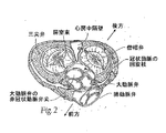
脊椎動物では、心臓は、図1に示すように、左心房および右心房ならびに左心室および右心室の4つのポンプ部屋を有する中空筋肉器官であり、その各々の部屋には、独自の一方向弁が設けられる。生体心臓弁は、大動脈弁、僧帽弁(または二尖弁)、三尖弁、および肺動脈弁として識別され、その各々は、心房および心室筋線維に直接的または間接的に取り付けられる緻密線維輪を備える弁輪に装着されている。各弁輪は、流動口を画定する。 In vertebrates, the heart is a hollow muscular organ having four pump chambers, the left and right atria and the left and right ventricles, as shown in FIG. Is provided. Living heart valves are identified as aortic, mitral (or bicuspid), tricuspid, and pulmonary valves, each of which is a dense annulus attached directly or indirectly to the atrial and ventricular muscle fibers It is attached to the annulus provided with. Each annulus defines a flow port.
心房は、血液を受容する部屋であって、血液を心室に送出する部屋である。心室は、血液を拍出する部屋である。心房中隔と呼ばれる、線維部分および筋肉部分から構成される壁は、右心房と左心房とを分離する(図2〜図4参照)。線維心房中隔は、心臓のもろい筋組織に比べて、物質的に強力な組織構造である。心房中隔上の解剖学的ランドマークは、卵形であり、親指の指紋サイズの窪みは、卵円窩(oval fossaまたはfossa ovalis)と呼ばれる(図4に示す)。 The atrium is a room for receiving blood and delivering blood to the ventricle. The ventricle is a room that pumps blood. A wall made up of fiber and muscle parts, called the atrial septum, separates the right and left atria (see FIGS. 2-4). The fibrous atrial septum is a materially strong tissue structure compared to the friable muscle tissue of the heart. The anatomical landmark on the atrial septum is oval and the fingerprint-sized depression on the thumb is called the oval fossa or fossa ovalis (shown in FIG. 4).
心臓の左側および右側の同期ポンプ作用は、心周期を構成する。周期は、心室拡張と呼ばれる心室弛緩の周期で始まる。周期は、心室収縮と呼ばれる心室収縮の周期で終わる。4つの弁(図2および図3参照)によって、心周期中に血液が誤った方向に流れないようにし、すなわち、血液が心室から対応する心房に逆流しないようにするか、または動脈から対応する心室に逆流しないようにする。僧帽弁は、左心房と左心室との間にあり、三尖弁は、右心房と右心室との間にあり、肺動脈弁は、肺動脈の開口部にあり、大動脈弁は、大動脈の開口部にある。 Synchronous pumping of the left and right sides of the heart constitutes the cardiac cycle. The cycle begins with a cycle of ventricular relaxation called ventricular dilatation. The cycle ends with a cycle of ventricular contraction called ventricular contraction. Four valves (see FIGS. 2 and 3) prevent blood from flowing in the wrong direction during the cardiac cycle, i.e. prevent blood from flowing back from the ventricle into the corresponding atrium or from the artery Avoid backflow into the ventricle. The mitral valve is between the left atrium and the left ventricle, the tricuspid valve is between the right atrium and the right ventricle, the pulmonary valve is at the opening of the pulmonary artery, and the aortic valve is the opening of the aorta In the department.
図2および図3は、大動脈弁の非冠状弁尖に当接する僧帽弁輪の前方(A)部分を示す。僧帽弁輪は、左冠状動脈の回旋枝に近接して存在し、後方(P)側は、冠状静脈洞およびその分岐付近に存在する。 2 and 3 show the anterior (A) portion of the mitral annulus that abuts the non-coronary leaflet of the aortic valve. The mitral valve annulus is in close proximity to the circumflex branch of the left coronary artery, and the posterior (P) side is near the coronary sinus and its branches.
僧帽弁および三尖弁は、心臓の線維骨格の一部を形成する、それぞれ弁輪と呼ばれるコラーゲンの線維輪によって画定される。弁輪は、僧帽弁の2つの尖頭または弁尖(前尖および後尖と呼ばれる)および三尖弁の3つの尖頭または弁尖に対する周辺取付を提供する。弁尖の自由端は、図1に示すように、1つより多くの乳頭筋からの腱索に連結する。健康な心臓では、これらの筋肉およびその腱索は、僧帽弁および三尖弁を支持し、これにより、弁尖は、左心室および右心室の収縮(拍出)期に発生する高圧に抵抗することができる。 Mitral and tricuspid valves are defined by collagen annulus, each called annulus, which forms part of the heart's fibrotic skeleton. The annulus provides peripheral attachment to the two cusps or leaflets of the mitral valve (referred to as the anterior and posterior leaflets) and the three cusps or leaflets of the tricuspid valve. The free ends of the leaflets connect to chordae from more than one papillary muscle, as shown in FIG. In a healthy heart, these muscles and their chords support the mitral and tricuspid valves, so that the leaflets resist the high pressures that occur during the left and right ventricular contractions (pumping) can do.
左心房からの血液で充満した後に左心室が収縮すると、心室の壁は、内側に移動し、乳頭筋および腱からの張力の一部を解放する。僧帽弁尖の下面を押し上げる血液は、それらを僧帽弁の弁輪面に向かって上昇させる。血液が弁輪に向かって進むにつれて、前尖および後尖の先端が結合して封止を形成し、弁を閉鎖する。健康な心臓では、弁尖の接合は、僧帽弁輪の平面付近で発生する。血液は、血液が大動脈に押し出されるまで左心室内で加圧され続ける。乳頭筋の収縮は、心室の収縮と同時に起こり、心室が及ぼすピーク収縮圧において健康な弁尖の密閉を維持する役割を果たす。 When the left ventricle contracts after filling with blood from the left atrium, the ventricular wall moves inward, releasing some of the tension from the papillary muscles and tendons. The blood that pushes up the lower surface of the mitral valve leaflets raises them toward the mitral valve annulus. As blood advances toward the annulus, the tips of the anterior and posterior cusps combine to form a seal and close the valve. In a healthy heart, valve leaflet junctions occur near the plane of the mitral annulus. The blood continues to be pressurized in the left ventricle until the blood is pushed out into the aorta. Papillary muscle contraction occurs simultaneously with ventricular contraction and serves to maintain a healthy leaflet seal at the peak contraction pressure exerted by the ventricle.
種々の外科技術を使用して、罹患弁または損傷弁を修復してもよい。弁置換手術では、損傷した弁尖が切除され、置換弁を受容するように弁輪の形が変えられる。大動脈弁狭窄症および他の心臓弁疾患により、何千人もの患者が毎年手術を受け、欠陥のある天然心臓弁が、生体弁または機械弁である人工弁と置換される。欠陥弁を処置するための緩和的な別の方法は、修復または再構築によるものであり、これは、典型的には、石灰化が最小限である弁に使用される。外科的治療に関する問題として、これらの慢性疾患者に外科的治療が課す重大な発作が挙げられ、外科的修復に関連する高い罹患率および死亡率がもたらされる。 Various surgical techniques may be used to repair the diseased or damaged valve. In valve replacement surgery, damaged leaflets are removed and the annulus shape is changed to accept the replacement valve. Aortic stenosis and other heart valve diseases cause thousands of patients to undergo surgery each year, replacing a defective natural heart valve with a prosthetic valve that is a living or mechanical valve. Another palliative method for treating a defective valve is by repair or remodeling, which is typically used for valves with minimal calcification. Problems with surgical treatment include the serious seizures that surgical treatment imposes on these chronically ill patients, resulting in high morbidity and mortality associated with surgical repair.
弁が置換される時に、人工弁の外科的埋込みは、典型的には、開胸手術を必要とし、その間に、心臓が止められ、患者が心配バイパス(いわゆる「人工心肺装置」)に設置される。1つの一般的な外科的手技では、罹患した天然弁尖が切除され、人工弁が弁輪における周辺組織に縫合される。手技と関連する外傷、および体外血液循環の付随持続時間のため、外科的手技に耐え抜かない、またはその直後に死亡する患者もいる。患者へのリスクは、体外循環に必要とされる時間量とともに増加することが周知である。これらのリスクにより、症状が虚弱すぎて手技に耐えられないため、欠陥弁がある相当数の患者が手術不可能と見なされる。概算により、80歳以上である、大動脈弁狭窄症に罹患した被検者の約30〜50%が、大動脈弁置換術のために手術を受けることができない。 When the valve is replaced, surgical implantation of the prosthetic valve typically requires a thoracotomy, during which time the heart is stopped and the patient is placed in a concern bypass (so-called “cardiopulmonary apparatus”) The In one common surgical procedure, the affected natural leaflet is resected and a prosthetic valve is sutured to the surrounding tissue in the annulus. Some patients may not survive the surgical procedure or die soon after because of the trauma associated with the procedure and the accompanying duration of extracorporeal blood circulation. It is well known that patient risk increases with the amount of time required for extracorporeal circulation. Because of these risks, a significant number of patients with defective valves are considered inoperable because their symptoms are too weak to withstand the procedure. Roughly, about 30-50% of subjects suffering from aortic stenosis who are over 80 years of age cannot undergo surgery for aortic valve replacement.
従来の開胸手術と関連する欠点により、経皮および低侵襲外科的アプローチが強い注目を集めている。1つの技法では、人工弁は、カテーテル法を介して、はるかに低侵襲的な手技で埋め込まれるように構成される。例えば、Andersenらへの米国特許第5,411,552号は、カテーテルを通して圧縮状態で経皮的に導入され、バルーン膨張によって所望の位置で拡張される、折畳み可能弁を説明している。これらの遠隔埋込み技法は、ある患者を治療するために非常に有望であるが、外科的介入を介して弁を置換することは、依然として好ましい治療手技である。遠隔埋込みの受け入れにとっての1つの障害は、不完全であれば、効果的な治療計画から、優れた成果を約束するが比較的なじみのない新規のアプローチに変換することについて、理解可能に不安を抱く、医師からの抵抗である。心臓弁置換の新しい技法に切り替える際の外科医による理解可能な注意と併せて、世界中の規制機関も動きが遅い。多数の成功した臨床試験および追跡研究が進行中であるが、それらが完全に受け入れられる前に、これらの新しい技術を用いたさらなる経験が必要とされるであろう。 Due to the shortcomings associated with conventional thoracotomy, percutaneous and minimally invasive surgical approaches have received considerable attention. In one technique, the prosthetic valve is configured to be implanted with a much less invasive procedure via catheterization. For example, US Pat. No. 5,411,552 to Andersen et al. Describes a foldable valve that is introduced percutaneously in a compressed state through a catheter and expanded in a desired position by balloon inflation. Although these teleimplantation techniques are very promising for treating certain patients, replacing the valve through surgical intervention remains a preferred treatment procedure. One obstacle to the acceptance of remote implantation is understandable anxiety about transforming, if incomplete, an effective treatment plan into a new approach that promises good results but is relatively unfamiliar. It is the resistance from the doctors. Regulatory agencies around the world are also slow, along with understandable surgeons' attention when switching to new techniques for heart valve replacement. A number of successful clinical trials and follow-up studies are underway, but further experience with these new technologies will be required before they are fully accepted.
したがって、体外循環に必要とされる時間を削減する、より効率的な手技で、人工弁を身体流路に外科的に埋め込むことができる、改良されたデバイスおよび関連使用方法の必要性がある。そのようなデバイスおよび方法は、症状が虚弱すぎて長時間に及ぶ従来の外科的手技に耐えられないため、手術不可能と見なされる欠陥弁がある患者を救うことができることが望ましい。本発明は、これらおよび他の必要性に対処する。 Accordingly, there is a need for an improved device and associated method of use that allows a prosthetic valve to be surgically implanted in a body flow path with a more efficient procedure that reduces the time required for extracorporeal circulation. It would be desirable to be able to save patients with defective valves that are considered inoperable because such devices and methods are too weak to withstand long-standing conventional surgical procedures. The present invention addresses these and other needs.
本願の種々の実施形態は、ヒトの心臓の中の欠陥天然弁を置換するための人工弁および使用方法を提供する。ある実施形態は、体外循環(すなわち、バイパスポンプ)を使用して時間を最小化しながら、迅速かつ容易に心臓弁を置換するための外科的手技で使用するために、特によく適合される。 Various embodiments of the present application provide a prosthetic valve and method of use to replace a defective natural valve in a human heart. Certain embodiments are particularly well adapted for use in surgical procedures to quickly and easily replace heart valves while minimizing time using extracorporeal circulation (ie, a bypass pump).
一実施形態では、大動脈弁の機能を置換するようにヒトの心臓の中の天然大動脈弁を治療するための方法は、1)胸部の開口部を通して天然弁にアクセスするステップと、2)天然大動脈弁の部位まで拡張可能な基礎ステントを前進させるステップであって、基礎ステントは前進中に半径方向に圧縮される、ステップと、3)天然大動脈弁の部位で基礎ステントを半径方向に拡張するステップと、4)基礎ステントの管腔内で弁構成要素を前進させるステップと、5)迅速かつ効率的な方式で、基礎ステントに機械的に連結するように、弁構成要素上の連結ステントを拡張するステップとを含む。 In one embodiment, a method for treating a natural aortic valve in a human heart to replace the function of the aortic valve comprises 1) accessing the natural valve through a thoracic opening, and 2) a natural aorta. Advancing an expandable basal stent to the site of the valve, wherein the basal stent is radially compressed during advancement, and 3) radially expanding the basal stent at the site of the natural aortic valve And 4) advancing the valve component within the lumen of the base stent, and 5) expanding the connecting stent on the valve component to mechanically connect to the base stent in a quick and efficient manner. Including the step of.
一変化例では、基礎ステントは、金属フレームを備えてもよい。一実施形態では、金属フレームの少なくとも一部分は、ステンレス鋼でできている。別の実施形態では、金属フレームの少なくとも一部分は、形状記憶材料でできている。弁部材は、種々の形態を成してもよい。1つの好ましい実施形態では、弁構成要素は生物組織を備える。この方法の別の変化例では、金属フレームは、天然大動脈弁に向かった人工弁の前進中に、蛍光透視法下で視認される。 In one variation, the base stent may comprise a metal frame. In one embodiment, at least a portion of the metal frame is made of stainless steel. In another embodiment, at least a portion of the metal frame is made of a shape memory material. The valve member may take various forms. In one preferred embodiment, the valve component comprises biological tissue. In another variation of this method, the metal frame is viewed under fluoroscopy during the advancement of the prosthetic valve toward the natural aortic valve.
天然弁尖は、人工弁を送達するまえに除去されてもよい。代替として、天然弁尖は、手術時間を削減するように、および天然弁内で基礎ステントを固定するための安定した基礎を提供するように、適所に残されてもよい。この方法の1つの利点では、天然弁尖が内向きに跳ね返り、身体流路の中の金属フレームの固定を強化する。天然弁尖が適所に残されると、弁尖を押しのけ、それにより、基礎ステントの埋込み前に天然弁を拡張するために、バルーンまたは他の拡張部材が使用されてもよい。天然弁輪は、より大きいサイズの人工弁に適応するように、それらの初期開口サイズから1.5乃至5mmの間で拡張されてもよい。 The natural leaflet may be removed before delivering the prosthetic valve. Alternatively, the natural leaflets may be left in place to reduce operative time and to provide a stable foundation for securing the base stent within the natural valve. One advantage of this method is that the natural leaflets rebound inward, enhancing the fixation of the metal frame in the body flow path. Once the native leaflet is left in place, a balloon or other expansion member may be used to displace the leaflet and thereby expand the native valve prior to implantation of the base stent. Natural annulus may be expanded between 1.5 to 5 mm from their initial opening size to accommodate larger sized prosthetic valves.
好ましい側面によれば、人工心臓弁システムは、心臓弁輪に対して固着するように適合され、その中に開口を画定する、基礎ステントと、基礎ステントに接続される弁構成要素とを備える。弁構成要素は、拡張不可能で折畳み不可能な開口を画定する、人工弁と、その流入端から延在する拡張可能な連結ステントとを含む。連結ステントは、埋込み位置に送達するための収縮状態と、基礎ステントへの外向き接続のために構成される拡張状態とを有する。基礎ステントはまた、心臓弁輪に隣接する埋込み位置に送達するための収縮状態、および心臓弁輪に接触し、それに対して固着するようにサイズ決定される拡張状態を伴って、拡張可能であってもよい。望ましくは、基礎ステント、および連結ステントも、塑性的に拡張可能である。 According to a preferred aspect, a prosthetic heart valve system comprises a base stent and a valve component connected to the base stent that are adapted to be secured to a heart valve annulus and that define an opening therein. The valve component includes a prosthetic valve that defines an unexpandable and non-foldable opening and an expandable connecting stent extending from its inflow end. The connecting stent has a contracted state for delivery to the implantation location and an expanded state configured for outward connection to the base stent. The base stent is also expandable with a contracted state for delivery to an implantation location adjacent to the heart annulus and an expanded state sized to contact and anchor to the heart annulus. May be. Desirably, the base stent and the connecting stent are also plastically expandable.
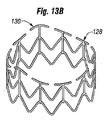
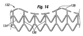
一実施形態では、人工弁は、縫製輪を有する市販の弁を備え、連結ステントは、縫製輪に取り付く。連結ステントの収縮状態は、円錐形であってもよく、遠位方向に先細りになる。連結ステントは、好ましくは、そのうちの少なくともいくつかが複数の列を成して配設される、複数の半径方向に拡張可能な支柱を備え、最遠位の列は、収縮状態から拡張状態への拡張に対して最大能力を有する。なおもさらに、人工弁から最も遠い支柱列は、交互する頂点と谷間とを有し、基礎ステントは、2つのステントを相互係止するように連結ステントの頂点が突出してもよい、開口を含む。基礎ステントは、軸方向に配向した支柱の間に複数の半径方向に拡張可能な支柱を含んでもよく、軸方向に配向した支柱のうちの少なくともいくつかは、ステントの周囲の場所の境界を定める上部突起を有する。 In one embodiment, the prosthetic valve comprises a commercially available valve having a sewing ring and the connecting stent attaches to the sewing ring. The contracted state of the connecting stent may be conical and tapers distally. The connecting stent preferably comprises a plurality of radially expandable struts, at least some of which are arranged in a plurality of rows, the most distal row being from a contracted state to an expanded state. It has the maximum capacity for expansion. Still further, the strut row furthest from the prosthetic valve has alternating vertices and valleys, and the base stent includes an opening through which the apex of the connecting stent may protrude to interlock the two stents. . The base stent may include a plurality of radially expandable struts between axially oriented struts, at least some of the axially oriented struts bounding a location around the stent. Has an upper protrusion.
人工心臓弁システムの送達および埋込みの方法も本明細書で開示され、
心臓弁輪に隣接する埋込み位置まで基礎ステントを前進させるステップと、
基礎ステントを心臓弁輪に固着するステップと、
拡張不可能で折畳み不可能な開口を有する、人工弁を含む弁構成要素を提供するステップであって、弁構成要素は、その流入端から延在する拡張可能連結ステントをさらに含み、連結ステントは、埋込み位置に送達するための収縮状態と、基礎ステントへの外向き接続のために構成される拡張状態とを有する、ステップと、
基礎ステントに隣接する埋込み位置まで、その収縮状態である連結ステントとともに弁構成要素を前進させるステップと、
基礎ステントと接触し、それに接続された拡張状態に連結ステントを拡張するステップと
を含む。
Also disclosed herein are methods for delivery and implantation of a prosthetic heart valve system.
Advancing the base stent to an implantation position adjacent to the heart valve annulus;
Securing the base stent to the heart valve annulus;
Providing a valve component including a prosthetic valve having an unexpandable and non-foldable opening, the valve component further comprising an expandable connecting stent extending from an inflow end thereof, wherein the connecting stent is Having a contracted state for delivery to the implantation location and an expanded state configured for outward connection to the base stent;
Advancing the valve component with the connected stent in its contracted state to an implantation position adjacent to the base stent;
Contacting the base stent and expanding the connecting stent to an expanded state connected thereto.
基礎ステントは、塑性的に拡張可能であってもよく、方法はさらに、埋込み位置まで収縮状態の拡張可能基礎ステントを前進させるステップと、心臓弁輪の開口サイズを少なくとも10%または1.5乃至5mmだけ増加させる過程において、心臓弁輪に接触し、それに固着した拡張状態に基礎ステントを塑性的に拡張するステップとを含む。望ましくは、弁構成要素の人工弁は、心臓弁輪の増加した開口サイズに合致する、開口サイズを有するように選択される。方法はまた、機械的拡張器上に基礎ステントを載置するステップと、機械的拡張器を使用して心臓弁輪で基礎ステントを配備するステップとを含んでもよい。 The base stent may be plastically expandable, and the method further includes advancing the contractible expandable base stent to an implantation position and reducing the heart valve annulus opening size to at least 10% or 1.5 to In the process of increasing by 5 mm, plastically expanding the base stent to an expanded state contacting and secured to the heart valve annulus. Desirably, the valve component prosthetic valve is selected to have an aperture size that matches the increased aperture size of the heart annulus. The method may also include placing a base stent on the mechanical dilator and deploying the base stent with the heart annulus using the mechanical dilator.
方法の一実施例はさらに、近位ハブと、それを通る管腔とを有する、ホルダ上に弁構成要素を載置するステップを含む。ホルダは、それを通る管腔を有するハンドルの遠位端上に載置し、方法は、ハンドルおよびホルダの管腔を通して、弁構成要素内でバルーンカテーテルを通過させるステップと、連結ステントを拡張するようにバルーンカテーテル上のバルーンを膨張させるステップとを含む。ホルダ上に載置された弁構成要素は、ハンドルおよびバルーンカテーテルとは別に包装されてもよい。望ましくは、連結ステントの収縮状態は、円錐形であり、バルーンカテーテル上のバルーンは、人工弁よりも連結ステントに多大な拡張偏向を印加するように、その近位拡張端よりも大きい遠位拡張端を有する。 One embodiment of the method further includes mounting a valve component on the holder having a proximal hub and a lumen therethrough. The holder rests on the distal end of the handle having a lumen therethrough and the method passes the balloon catheter through the handle and the lumen of the holder and within the valve component, and expands the connecting stent. Inflating the balloon on the balloon catheter. The valve component mounted on the holder may be packaged separately from the handle and balloon catheter. Desirably, the contracted state of the connecting stent is conical and the balloon on the balloon catheter is distally expanded larger than its proximal expanded end so as to apply greater expansion deflection to the connecting stent than the prosthetic valve. Has an edge.
連結ステントが円錐形である方法では、連結ステントは、そのうちの少なくともいくつかが列を成して配設される、複数の半径方向に拡張可能な支柱を備えてもよく、人工弁から最も遠い列は、収縮状態から拡張状態への拡張に対して最大能力を有する。 In methods where the connecting stent is conical, the connecting stent may comprise a plurality of radially expandable struts, at least some of which are arranged in rows, furthest from the prosthetic valve. The column has maximum capacity for expansion from the contracted state to the expanded state.
方法は、複数の半径方向に拡張可能な支柱を有する連結ステントを採用してもよく、人工弁から最も遠い列は、交互する頂点と谷間とを有する。したがって、連結ステントの遠位端は、人工弁から最も遠い列における頂点が、基礎ステントの開口の中へ外向きに突出するように、連結ステントの他の部分よりも拡張する。基礎ステントおよび連結ステントの両方は、軸方向に配向した支柱の間に複数の半径方向に拡張可能な支柱を有してもよく、方法は、連結ステントを配向することにより、それの軸方向に配向した支柱が、基礎ステントの支柱との位相がずれて、自身の間での保持を増加させる、ことを含む。 The method may employ a connected stent having a plurality of radially expandable struts, with the row furthest from the prosthetic valve having alternating vertices and valleys. Thus, the distal end of the connected stent expands beyond the rest of the connected stent so that the apex in the row farthest from the prosthetic valve protrudes outward into the opening of the base stent. Both the base stent and the connecting stent may have a plurality of radially expandable struts between the axially oriented struts, and the method can be achieved by orienting the connecting stent in its axial direction. The oriented struts are out of phase with the struts of the base stent to increase retention between themselves.
本明細書で説明される別の側面は、拡張不可能で折畳み不可能な開口を有する、人工弁と、その流入端から延在する拡張可能連結ステントであって、埋込み位置に送達するための収縮状態と、拡張状態とを有する、連結ステントとを含む、弁構成要素を送達するためのシステムである。送達システムは、弁構成要素の近位端に接続される弁ホルダと、バルーンを有するバルーンカテーテルと、弁ホルダの近位端に取り付くように構成され、カテーテルの通過のための管腔を有する、ハンドルとを含み、バルーンは、ハンドルを通り、ホルダを越え、弁構成要素を通って遠位に延在する。システムでは、人工弁は、好ましくは、連結ステントが取り付く縫製輪を有する、市販の弁である。 Another aspect described herein is a prosthetic valve having an unexpandable and non-foldable opening and an expandable connecting stent extending from its inflow end for delivery to an implantation position A system for delivering a valve component comprising a connected stent having a contracted state and an expanded state. The delivery system includes a valve holder connected to the proximal end of the valve component, a balloon catheter having a balloon, a lumen configured to attach to the proximal end of the valve holder, and having a lumen for passage of the catheter. And the balloon extends distally through the handle, beyond the holder and through the valve component. In the system, the prosthetic valve is preferably a commercially available valve with a sewing ring to which the connecting stent is attached.
送達システムの中の連結ステントの収縮状態は、円錐形であってもよく、遠位方向に先細りになる。その上、バルーンカテーテルはさらに、遠位方向に先細りになり、前記バルーンカテーテルはさらに、弁構成要素を通って延在し、その収縮状態である連結ステントの遠位端に係合する、略円錐形ノーズコーンをその遠位端上に含んでもよい。望ましくは、ハンドルは、連続管腔を形成するようにともに直列で連結されてもよい、近位セクションおよび遠位セクションを備え、遠位セクションは、近位ハンドルセクションとの接続の前に、ホルダのハブに連結して、遠位セクションを使用した弁構成要素の手動操作を可能にするように適合される。好ましくは、バルーンカテーテルおよび近位ハンドルセクションは、近位セクション管腔内のバルーンとともに包装される。 The contracted state of the connecting stent in the delivery system may be conical and tapers distally. In addition, the balloon catheter is further tapered in a distal direction, the balloon catheter further extending through the valve component and engaging the distal end of the contracted connecting stent. A shaped nose cone may be included on its distal end. Desirably, the handle comprises a proximal section and a distal section that may be coupled together in series to form a continuous lumen, the distal section being a holder prior to connection with the proximal handle section. And is adapted to allow manual operation of the valve component using the distal section. Preferably, the balloon catheter and proximal handle section are packaged with a balloon in the proximal section lumen.
ホルダ上に載置された弁構成要素は、ハンドルおよびバルーンカテーテルとは別に包装される、請求項21に記載のシステムである。本発明の性質および利点のさらなり理解は、特に、類似部品が類似参照数字を持つ、添付図面と併せて考慮すると、以下の説明および請求項で説明される。
本発明は、例えば、以下を提供する。
(項目1)
人工心臓弁システムであって、
心臓弁輪に対して固着するように適合され、自身の中に開口を画定する基礎ステントと、
人工弁を含む弁構成要素であって、該人工弁は、自身の中に拡張不可能で折畳み不可能な開口を画定し、該弁構成要素は、自身の流入端から延在する拡張可能連結ステントをさらに含み、該連結ステントは、埋込み位置への送達のための収縮状態と、該基礎ステントへの外向きの接続のために構成される拡張状態とを有する、弁構成要素と
を備える、人工心臓弁システム。
(項目2)
上記基礎ステントは、拡張可能であり、心臓弁輪に隣接する埋込み位置への送達のための収縮状態と、該心臓弁輪に接触し、該心臓弁輪に対して固着するようにサイズ決定された拡張状態とを有する、項目1に記載のシステム。
(項目3)
上記基礎ステントは、塑性的に拡張可能である、項目2に記載のシステム。
(項目4)
上記連結ステントは、塑性的に拡張可能である、項目1に記載のシステム。
(項目5)
上記人工弁は、縫製輪を有する市販の弁を備え、上記連結ステントは、該縫製輪に取り付く、項目1に記載のシステム。
(項目6)
上記連結ステントの上記収縮状態は、円錐形であり、遠位方向に先細りになる、項目1に記載のシステム。
(項目7)
上記連結ステントは、複数の半径方向に拡張可能な支柱を備え、該支柱のうちの少なくともいくつかが複数の列を成して配設され、最遠位の列は、上記収縮状態から上記拡張状態への拡張に対して最大能力を有する、項目6に記載のシステム。
(項目8)
上記連結ステントは、複数の半径方向に拡張可能な支柱を備え、上記人工弁から最も遠い列は、交互する頂点と谷間とを有し、上記基礎ステントは、開口を含み、該連結ステントの頂点が該開口の中に突出して、該2つのステントを相互に係止し得る、項目1に記載のシステム。
(項目9)
上記基礎ステントは、軸方向に配向した支柱の間に複数の半径方向に拡張可能な支柱を含み、該軸方向に配向した支柱のうちの少なくともいくつかは、該ステントの周囲の場所の境界を定める上部突起を有する、項目1に記載のシステム。
(項目10)
人工心臓弁システムの送達および埋込みの方法であって、
基礎ステントを心臓弁輪に隣接する埋込み位置まで前進させることと、
該基礎ステントを該心臓弁輪に固着することと、
人工弁を含む弁構成要素を提供することであって、該人工弁は、拡張不可能で折畳み不可能な開口を有し、該弁構成要素は、自身の流入端から延在する拡張可能な連結ステントをさらに含み、該連結ステントは、埋込み位置への送達のための収縮状態と、該基礎ステントへの外向き接続のために構成される拡張状態とを有する、ことと、
該基礎ステントに隣接する埋込み位置まで、収縮状態にある該連結ステントとともに該弁構成要素を前進させることと、
該基礎ステントと接触した状態で、それに接続される該拡張状態まで該連結ステントを拡張することと
を含む、方法。
(項目11)
上記基礎ステントは、塑性的に拡張可能であり、
収縮状態にある該拡張可能な基礎ステントを上記埋込み位置まで前進させることと、
上記心臓弁輪の開口サイズを少なくとも10%だけ増加させる過程において、該心臓弁輪に接触し、それに固着した拡張状態まで該基礎ステントを塑性的に拡張することと
をさらに含む、項目10に記載の方法。
(項目12)
上記弁構成要素の上記人工弁は、上記心臓弁輪の上記増加した開口サイズに合致する開口サイズを有するように選択される、項目11に記載の方法。
(項目13)
機械的拡張器上に上記基礎ステントを載置することと、該機械的拡張器を使用して上記心臓弁輪において該基礎ステントを配備することとをさらに含む、項目11に記載の方法。
(項目14)
近位ハブと、自身を通る管腔とを有するホルダ上に上記弁構成要素を載置することと、ハンドルの遠位端に該ホルダを載置することであって、該ハンドルは自身を通る管腔を有する、こととをさらに含み、該方法は、該ハンドルの管腔および該ホルダを通して、該弁構成要素内においてバルーンカテーテルを通過させることと、該バルーンカテーテル上のバルーンを膨張させて、該連結ステントを拡張することとを含む、項目10に記載の方法。
(項目15)
上記ハンドルおよび上記バルーンカテーテルとは別に、上記ホルダ上に載置された上記弁構成要素を包装することをさらに含む、項目14に記載の方法。
(項目16)
上記連結ステントの上記収縮状態は、円錐形であり、上記バルーンカテーテル上の上記バルーンは、それの近位拡張端よりも大きい遠位拡張端を有することによって、上記人工弁によりも該連結ステントに、より多大な拡張偏向を印加する、項目14に記載の方法。
(項目17)
上記連結ステントの上記収縮状態は、円錐形であり、該連結ステントは、複数の半径方向に拡張可能な支柱を備え、該支柱のうちの少なくともいくつかが列を成して配設され、該人工弁から最も遠い列は、該収縮状態から上記拡張状態への拡張に対して最大能力を有する、項目10に記載の方法。
(項目18)
上記連結ステントは、複数の半径方向に拡張可能な支柱を備え、上記人工弁から最も遠い列は、交互する頂点と谷間とを有し、上記方法は、該連結ステントの遠位端を該連結ステントの他の部分よりも拡張することにより、該人工弁から最も遠い列における該頂点が、上記基礎ステントの開口の中へ外向きに突出する、こととを含む、項目10に記載の方法。
(項目19)
上記基礎ステントおよび上記連結ステントの両方は、複数の軸方向に配向した支柱の間に複数の半径方向に拡張可能な支柱を有し、上記方法は、該連結ステントを配向することにより、それの軸方向に配向した支柱が、該基礎ステントの支柱との位相がずれて、その間での保持を増加させる、ことを含む、項目10に記載の方法。
(項目20)
上記基礎ステントを塑性的に拡張することによって、上記心臓弁輪の開口サイズを1.5乃至5mmだけ増加させることを含む、項目10に記載の方法。
(項目21)
人工心臓弁を送達するシステムであって、
人工弁を含む弁構成要素であって、該人工弁は、上記拡張不可能で折畳み不可能な開口を有し、該弁構成要素は、自身の流入端から延在する拡張可能な連結ステントをさらに含み、該連結ステントは、埋込み位置への送達のための収縮状態と、拡張状態とを有する、弁構成要素と、
該弁構成要素の近位端に接続される弁ホルダと、
バルーンを有するバルーンカテーテルと、
該弁ホルダの近位端に取り付くように構成され、該カテーテルの通過のための管腔を有するハンドルであって、該バルーンは、該ハンドルを通り、該ホルダを越え、該弁構成要素を通って遠位に延在する、ハンドルと
を備える、システム。
(項目22)
上記人工弁は、縫製輪を有する市販の弁を備え、上記連結ステントは、該縫製輪に取り付く、項目21に記載のシステム。
(項目23)
上記連結ステントの上記収縮状態は、円錐形であり、遠位方向に先細りになる、項目21に記載のシステム。
(項目24)
上記連結ステントの上記収縮状態は、円錐形で、遠位方向に先細りになり、上記バルーンカテーテルは、自身の遠位端に略円錐形のノーズコーンを含み、上記弁構成要素を通って延伸し、収縮状態にある該連結ステントの遠位端に係合する、項目21に記載のシステム。
(項目25)
上記ハンドルは、連続管腔を形成するようにともに直列に連結され得る近位セクションと遠位セクションとを備え、該遠位セクションは、該近位ハンドルセクションとの接続の前に上記ホルダのハブに連結して、該遠位セクションを使用する上記弁構成要素の手動操作を可能にするように適合される、項目21に記載のシステム。
(項目26)
上記バルーンカテーテルおよび近位ハンドルセクションは、上記近位セクション管腔内の上記バルーンとともに包装される、項目25に記載のシステム。
(項目27)
上記ホルダ上に載置された上記弁構成要素は、上記ハンドルおよび上記バルーンカテーテルとは別に包装される、項目21に記載のシステム。
24. The system of claim 21, wherein the valve component mounted on the holder is packaged separately from the handle and balloon catheter. A further understanding of the nature and advantages of the present invention is set forth in the following description and claims, particularly when considered in conjunction with the accompanying drawings wherein like parts bear like reference numerals.
For example, the present invention provides the following.
(Item 1)
An artificial heart valve system,
A base stent adapted to be secured to a heart valve annulus and defining an opening therein;
A valve component comprising a prosthetic valve, wherein the prosthetic valve defines an unexpandable and non-foldable opening therein, the valve component extending from its inflow end A valve component further comprising a stent, wherein the connecting stent has a contracted state for delivery to an implantation position and an expanded state configured for outward connection to the base stent;
An artificial heart valve system comprising:
(Item 2)
The base stent is expandable and sized to contract and deliver to the implant location adjacent to the heart valve annulus and to contact and anchor to the heart valve annulus. The system according to
(Item 3)
Item 3. The system of item 2, wherein the basic stent is plastically expandable.
(Item 4)
The system of
(Item 5)
The system according to
(Item 6)
The system of
(Item 7)
The connecting stent includes a plurality of radially expandable struts, at least some of the struts being arranged in a plurality of rows, the most distal row being expanded from the contracted state. Item 7. The system of item 6, having maximum capability for expansion to a state.
(Item 8)
The connected stent includes a plurality of radially expandable struts, the row furthest from the prosthetic valve has alternating vertices and valleys, the basic stent includes openings, and the connected stent vertices 2. The system of
(Item 9)
The base stent includes a plurality of radially expandable struts between axially oriented struts, at least some of the axially oriented struts demarcating a location around the stent. 2. The system of
(Item 10)
A method for delivery and implantation of a prosthetic heart valve system comprising:
Advancing the base stent to an implantation position adjacent to the heart valve annulus;
Affixing the base stent to the heart valve annulus;
Providing a valve component comprising a prosthetic valve, the prosthetic valve having an unexpandable and non-foldable opening, the expandable valve component extending from its inflow end Further comprising a connecting stent, the connecting stent having a contracted state for delivery to the implantation position and an expanded state configured for outward connection to the base stent;
Advancing the valve component with the connecting stent in a contracted state to an implantation position adjacent to the base stent;
Expanding the connected stent in contact with the base stent to the expanded state connected thereto.
Including a method.
(Item 11)
The basic stent is plastically expandable,
Advancing the expandable base stent in a contracted state to the implantation position;
Plastically expanding the base stent to an expanded state contacting and secured to the heart valve annulus in the process of increasing the opening size of the heart valve annulus by at least 10%;
The method according to item 10, further comprising:
(Item 12)
12. The method of item 11, wherein the prosthetic valve of the valve component is selected to have an aperture size that matches the increased aperture size of the heart annulus.
(Item 13)
12. The method of item 11, further comprising placing the basal stent on a mechanical dilator and deploying the basal stent in the heart valve annulus using the mechanical dilator.
(Item 14)
Mounting the valve component on a holder having a proximal hub and a lumen therethrough, and mounting the holder at a distal end of the handle, the handle passing through it. Further comprising passing a balloon catheter through the handle lumen and the holder within the valve component and inflating the balloon on the balloon catheter; 11. The method of item 10, comprising expanding the connecting stent.
(Item 15)
15. A method according to item 14, further comprising packaging the valve component mounted on the holder separately from the handle and the balloon catheter.
(Item 16)
The contracted state of the connecting stent is conical, and the balloon on the balloon catheter has a distal expanded end larger than its proximal expanded end, thereby allowing the prosthetic valve to also connect to the connecting stent. 15. A method according to item 14, wherein a greater amount of extended deflection is applied.
(Item 17)
The contracted state of the connecting stent is conical, the connecting stent comprising a plurality of radially expandable struts, at least some of the struts being arranged in rows, Item 11. The method of item 10, wherein the row farthest from the prosthetic valve has maximum capacity for expansion from the contracted state to the expanded state.
(Item 18)
The connecting stent includes a plurality of radially expandable struts, the row furthest from the prosthetic valve has alternating vertices and valleys, and the method includes connecting the distal ends of the connecting stents to the connecting stent. 11. The method of claim 10, comprising expanding the apex in a row furthest from the prosthetic valve by projecting more than other portions of the stent outwardly into the opening of the base stent.
(Item 19)
Both the base stent and the connecting stent have a plurality of radially expandable struts between a plurality of axially oriented struts, the method comprising: 11. A method according to item 10, wherein the axially oriented struts are out of phase with the base stent struts to increase retention therebetween.
(Item 20)
11. The method of item 10, comprising increasing the opening size of the heart valve annulus by 1.5 to 5 mm by plastically expanding the base stent.
(Item 21)
A system for delivering a prosthetic heart valve,
A valve component including a prosthetic valve, the prosthetic valve having the non-expandable and non-foldable opening, the valve component having an expandable connecting stent extending from its inflow end. And further comprising a valve component having a contracted state for delivery to the implantation position and an expanded state;
A valve holder connected to the proximal end of the valve component;
A balloon catheter having a balloon;
A handle configured to attach to a proximal end of the valve holder and having a lumen for passage of the catheter, the balloon passing through the handle, over the holder and through the valve component Extending distally with a handle
A system comprising:
(Item 22)
(Item 23)
22. The system of item 21, wherein the contracted state of the linking stent is conical and tapers distally.
(Item 24)
The contracted state of the connecting stent is conical and tapering distally, and the balloon catheter includes a generally conical nose cone at its distal end and extends through the valve component. 22. The system of item 21, wherein the system engages the distal end of the connecting stent in a contracted state.
(Item 25)
The handle includes a proximal section and a distal section that can be coupled together in series to form a continuous lumen, the distal section being a hub of the holder prior to connection with the proximal handle section.
(Item 26)
26. The system of item 25, wherein the balloon catheter and proximal handle section are packaged with the balloon in the proximal section lumen.
(Item 27)
ここで、本発明を説明し、添付概略図面を参照すると、他の利点および特徴が現れるであろう。
本発明は、従来の心臓切開手術と関連する欠点を克服しようとする一方で、治療手技の持続時間を減少させる、より新しい技術の技法のうちのいくつかをも採用する。本発明の人工心臓弁は、主に、前述の心臓切開手術を含む従来の外科技法を使用して、送達され、埋め込まれることを目的としている。そのような手術にはいくつかのアプローチがあり、その全ては、特定の心臓弁輪への直接アクセス経路の形成をもたらす。明確にするために、直接アクセス経路は、心臓弁輪の直接(すなわち、肉眼)可視化を可能にするものである。加えて、本明細書で説明される二段階人工心臓弁の実施形態はまた、経皮的アプローチを使用した送達、および間接可視化を使用した弁の遠隔埋込みを必要とする低侵襲外科的アプローチのために構成されてもよいことが認識されるであろう。 The present invention also employs some of the newer technical techniques that attempt to overcome the drawbacks associated with conventional open heart surgery while reducing the duration of the treatment procedure. The prosthetic heart valve of the present invention is primarily intended to be delivered and implanted using conventional surgical techniques including the aforementioned open heart surgery. There are several approaches to such surgery, all of which result in the formation of a direct access path to a specific heart valve annulus. For clarity, the direct access path allows direct (ie, naked) visualization of the heart annulus. In addition, the two-stage prosthetic heart valve embodiments described herein also provide for a minimally invasive surgical approach that requires delivery using a percutaneous approach and remote implantation of the valve using indirect visualization. It will be appreciated that may be configured for.
本発明の1つの主な側面は、二段階人工心臓弁であり、最初に組織アンカを、次いで弁部材を埋め込む作業は、明らかに異なり、ある利点が結果的に生じる。本発明の例示的な二段階人工心臓弁は、バルーンまたは他の拡張技法を使用して適切な場所で組織に固定される拡張可能基礎ステントを有する。次いで、拡張不可能および拡張可能部分を有するハイブリッド弁部材が、別個または次の動作において、基礎ステントに連結する。拡張可能基礎ステントを利用することによって、初期固着動作の持続時間は、縫合糸のアレイを利用する従来の縫製手技と比較して、大いに削減される。拡張可能基礎ステントは、単純に、埋込み部位と接触するように半径方向外向きに拡張されてもよく、または、鉤等の付加的な固着手段が提供されてもよい。手術は、従来の心臓切開アプローチおよび心肺バイパスを使用して実行されてもよい。1つの有利な特徴では、拡張可能基礎ステントを埋め込む相対的速度により、バイパスにかかる時間が大いに削減される。 One major aspect of the present invention is a two-stage prosthetic heart valve, the task of first implanting a tissue anchor and then a valve member is clearly different and results in certain advantages. An exemplary two-stage prosthetic heart valve of the present invention has an expandable basic stent that is secured to tissue in place using a balloon or other expansion technique. A hybrid valve member having non-expandable and expandable portions is then coupled to the base stent in a separate or subsequent operation. By utilizing an expandable basic stent, the duration of the initial anchoring operation is greatly reduced compared to conventional sewing procedures that utilize an array of sutures. The expandable base stent may simply be expanded radially outward to contact the implantation site, or additional anchoring means such as a heel may be provided. The surgery may be performed using a conventional cardiotomy approach and cardiopulmonary bypass. In one advantageous feature, the relative speed of implanting the expandable base stent greatly reduces the time it takes to bypass.
定義の目的で、「基礎ステント」という用語は、心臓弁輪の組織に取り付くことが可能な心臓弁の構造構成要素を指す。本明細書で説明される基礎ステントは、最も典型的には、管状ステント、または様々な形状または直径を有するステントである。ステントは、通常、ステンレス鋼またはNitinol等の生体適合性金属ワイヤフレームで形成される。本発明の弁とともに使用することができる他の基礎ステントは、剛体リング、らせん状に巻かれた管、および弁輪内で緊密に嵌合し、血液の通過のためにそれを通る開口を画定する、またはその内側に弁部材が載置される、他のそのような管を含む。しかしながら、基礎ステントは、連続周辺を画定しない別個のクランプまたはフックになり得ることが完全に考えられる。そのようなデバイスは、いくらかの動的安定性、ならびに配備の速度および容易性を犠牲にするが、これらのデバイスは、特定の弁部材と併せて稼働するように構成することができる。 For purposes of definition, the term “basic stent” refers to a structural component of a heart valve that can attach to the tissue of the heart annulus. The basic stents described herein are most typically tubular stents or stents having various shapes or diameters. The stent is typically formed of a biocompatible metal wire frame such as stainless steel or Nitinol. Other basic stents that can be used with the valve of the present invention include a rigid ring, a spirally wound tube, and an intimate fit within the annulus, defining an opening therethrough for the passage of blood. Or other such tubes on which the valve member is mounted. However, it is entirely contemplated that the base stent can be a separate clamp or hook that does not define a continuous perimeter. Such devices sacrifice some dynamic stability, and the speed and ease of deployment, but these devices can be configured to operate in conjunction with certain valve members.
自己拡張式およびバルーン拡張式ステントの間の区別が、当分野に存在する。自己拡張式ステントは、小さい管の中へ圧着または別様に圧縮されてもよく、外側シース等の拘束が除去されると、独力で外向きに跳ねることに十分な弾力性を保有する。対照的に、バルーン拡張式ステントは、大幅に弾力性が低い材料でできており、実際に、圧縮直径から拡張直径に返還するときに、内側から外側へ塑性的に拡張されなければならない。バルーン拡張式ステントという用語は、ステントを実際に拡張するためにバルーンが使用されるか否かにかかわらず、塑性的拡張可能ステントを包含することを理解されたい。ステントの材料は、膨張バルーンまたは拡張式機械的指部等の変形力の印加後に、塑性的に変形する。両方の代替案を以下で説明する。その結果として、「バルーン拡張可能ステント」という用語は、特定の拡張手段とは対照的な材料および種類のステントを指すと見なされるべきである。 A distinction exists in the art between self-expanding and balloon expandable stents. Self-expanding stents may be crimped or otherwise compressed into a small tube and retain sufficient resilience to jump out on their own when the constraints such as the outer sheath are removed. In contrast, balloon expandable stents are made of a material that is significantly less elastic and must actually be plastically expanded from the inside to the outside when returning from a compressed diameter to an expanded diameter. It should be understood that the term balloon expandable stent encompasses plastic expandable stents regardless of whether a balloon is used to actually expand the stent. The stent material deforms plastically after application of a deformation force, such as an inflatable balloon or an expandable mechanical finger. Both alternatives are described below. Consequently, the term “balloon expandable stent” should be taken to refer to a material and type of stent as opposed to a particular expansion means.
「弁部材」という用語は、1つの方向への血流を妨げる一方で、別の方向への血流を許可するように、流体閉塞面を保有する、心臓弁の構成要素を指す。上記のように、可撓性弁尖を伴う構造、ならびに剛体弁尖またはボールおよびケージ配設を伴う構造を含む、弁部材の種々の構造が利用可能である。弁尖は、生体、合成、または金属であってもよい。 The term “valve member” refers to a component of a heart valve that retains a fluid occlusion surface to prevent blood flow in one direction while permitting blood flow in another direction. As described above, various structures of valve members are available, including structures with flexible leaflets, and structures with rigid leaflets or ball and cage arrangements. The leaflets may be living, synthetic, or metal.
本発明の主な焦点は、基礎ステントが弁輪に固定する第一段階と、弁部材が基礎ステントに接続する後続の第二段階とを有する、二段階人工心臓弁である。これらの段階は、2つの構成要素が同じ送達デバイス上に載置されたかのように、ほぼ同時に行われてもよく、または、第一の送達デバイスを使用して基礎ステントが配備され、次いで、別の送達デバイスを使用して弁部材が配備される、2つの別個の臨床ステップで行うことができることに留意されたい。また、「二段階」という用語は、構造を弁輪に固着し、次いで、弁部材を接続するという2つの主なステップを指し、それは、必ずしも弁を2つだけの部品に限定しないことにも留意されたい。 The main focus of the present invention is a two-stage prosthetic heart valve having a first stage in which the base stent is secured to the annulus and a subsequent second stage in which the valve member connects to the base stent. These steps may be performed almost simultaneously as if the two components were mounted on the same delivery device, or the first delivery device was used to deploy the base stent and then another Note that this can be done in two separate clinical steps where the valve member is deployed using the same delivery device. The term “two-stage” also refers to the two main steps of securing the structure to the annulus and then connecting the valve members, which does not necessarily limit the valve to only two parts. Please keep in mind.
基礎ステントおよび弁部材を含む、二段階人工心臓弁の別の潜在的な便益は、基礎ステントを置換することなく、弁部材が埋込み後に置換されてもよいことである。つまり、新しい弁部材が比較的容易に埋め込まれることを可能にする、弁部材および基礎ステントを連結するための容易に着脱可能な手段が使用されてもよい。弁部材および基礎ステントを連結するための種々の構成が本明細書で説明される。 Another potential benefit of a two-stage prosthetic heart valve, including a base stent and valve member, is that the valve member may be replaced after implantation without replacing the base stent. That is, an easily removable means for connecting the valve member and the base stent may be used that allows the new valve member to be implanted relatively easily. Various configurations for connecting the valve member and the base stent are described herein.
したがって、本発明のある便益は、基礎ステントが拡張可能な否かとは無関係であることを理解されたい。つまり、種々の実施形態は、拡張不可能および拡張可能部分を有するハイブリッド弁部材に連結される、拡張可能基礎ステントを図示する。しかしながら、同じ連結構造が、拡張不可能基礎ステントおよびハイブリッド弁部材に利用されてもよい。したがって、本発明は、添付の請求項を介して解釈されるべきである。 Thus, it should be understood that certain benefits of the present invention are independent of whether the base stent is expandable. That is, various embodiments illustrate an expandable base stent that is coupled to a hybrid valve member having an unexpandable and expandable portion. However, the same connection structure may be utilized for non-expandable basic stents and hybrid valve members. Therefore, the present invention should be construed through the appended claims.
さらなる定義の点として、「拡張可能」という用語は、第一の送達直径から第2の埋込み直径に拡張することが可能な心臓弁の構成要素を指すために、本明細書で使用される。したがって、拡張可能構造とは、温度の上昇、または他のそのような偶発的事例から、わずかな拡張を受ける場合があるものを意味しない。逆に、「拡張不可能」とは、例えば、従来の「拡張不可能」心臓弁のいくらかのわずかな拡張が観察されてもよいため、完全剛体または寸法安定性であることを意味すると解釈されるべきではない。 As a further definition, the term “expandable” is used herein to refer to a component of a heart valve that is expandable from a first delivery diameter to a second implantation diameter. Thus, an expandable structure does not mean that it may be subject to slight expansion from elevated temperatures or other such incidental cases. Conversely, “non-expandable” is interpreted to mean full rigid or dimensional stability, for example, since some slight expansion of a conventional “non-expandable” heart valve may be observed. Should not.
以下の説明では、「身体流路」という用語は、体内の血液導管または血管を定義するために使用される。当然ながら、人工心臓弁の特定の用途が、問題の身体流路を判定する。例えば、大動脈弁置換は、大動脈弁輪に、またはそれに隣接して埋め込まれる。同様に、僧帽弁置換は、僧帽弁輪に埋め込まれる。本発明のある特徴は、一方または他方の埋込み部位にとって特に有利である。しかしながら、組み合わせが構造的に不可能ではない限り、または請求項の言葉によって除外されない限り、本明細書で説明される心臓弁の実施形態のうちのいずれかを、任意の身体流路に埋め込むことができる。 In the following description, the term “body channel” is used to define a blood conduit or blood vessel in the body. Of course, the particular application of the prosthetic heart valve determines the body flow path in question. For example, aortic valve replacement is implanted in or adjacent to the aortic annulus. Similarly, mitral valve replacement is implanted in the mitral annulus. Certain features of the invention are particularly advantageous for one or the other implantation site. However, unless any combination is structurally impossible or excluded by the language of the claims, any of the heart valve embodiments described herein are implanted in any body flow path. Can do.
図5A−5Hは、隣接する左心室LVおよび動脈洞Sを有する上行大動脈の一部分を示す、単独の大動脈弁輪AAを通る断面図である。2つの冠状静脈洞CSも示されている。一連の図は、二構成要素システムを備える、本発明の例示的な人工心臓弁システムの配備におけるいくつかのステップのスナップショットを示す。第一の構成要素は、天然弁尖に対して、または弁尖が切除される場合は創傷清拭した大動脈弁輪AAに対して配備される基礎ステントである。第2の弁構成要素は、基礎ステント内に嵌合し、それに固着する。二部品弁が当技術分野で公知であるが、これは、拡張不可能弁と併せて、ステント内でステントを利用する最初のものであると考えられる。 5A-5H are cross-sectional views through a single aortic annulus AA showing a portion of the ascending aorta with adjacent left ventricle LV and sinus S. FIG. Two coronary sinus CS are also shown. The series of figures shows a snapshot of several steps in the deployment of an exemplary prosthetic heart valve system of the present invention comprising a two component system. The first component is a basal stent that is deployed against the native leaflet, or against the wound aortic annulus AA if the leaflet is resected. The second valve component fits within the base stent and is secured thereto. Two-part valves are known in the art and are considered the first to utilize a stent within a stent in conjunction with a non-expandable valve.
図5Aは、カテーテル20を示し、カテーテルは、遠位端付近に収縮状態のバルーン22を有し、その上に管状基礎ステント24が圧着されている。ステント24は、半径方向に収縮された未配備構成で示されている。カテーテル20は、ほぼ軸方向に大動脈弁輪AAに中心があるように基礎ステント24を位置付けるように前進させられている。
FIG. 5A shows a
図5Bは、大動脈弁輪AAに対して基礎ステント24を拡張および配備するために膨張させられた、カテーテル20上のバルーン22を示し、図5Cは、バルーン22の収縮およびカテーテル20の除去後に適所にある、配備された基礎ステントを示す。ステント24は、身体管腔(例えば、弁輪)内で、それに対して基礎を提供する。例示の目的でステントが説明されているが、身体管腔内で、それに対して固着し、次いで、弁構成要素に連結することが可能な任意の部材が使用されてもよい。好ましい実施形態では、基礎ステント24は、塑性的に拡張可能な布で覆われたステンレス鋼管状ステントを備える。塑性的拡張可能ステントを使用することの1つの利点は、従来の手術で可能となるよりも大きい弁サイズを受容するように天然弁輪を拡張できる能力である。望ましくは、左心室流出路(LVOT)は、少なくとも10%、または、例えば1.5乃至5mmだけ有意に拡張され、外科医は、拡張していない弁輪と比べて、より大きい開口直径を有する弁構成要素30を選択することができる。一方では、本発明は、自己拡張式基礎ステント24を使用することができ、それは次に、後に埋め込まれる弁構成要素30によって補強することができる。弁構成要素30は、非圧縮性部品、人工弁34、および望ましくは塑性的拡張可能連結ステント36を有するので、自己拡張した基礎ステント24の跳ね返りに効果的に抵抗する。
FIG. 5B shows the
引き続き図5Bを参照して、ステント24は、(例えば、大動脈弁輪に沿った)天然弁の場所に配備されるようにサイズ決定された直径を有する。ステント24の一部分は、天然弁に隣接するそれぞれの空洞の中へ外向きに拡張してもよい。例えば、大動脈弁置換術では、上部分が、大動脈弁輪のすぐ下流にある動脈洞の領域の中へ拡張してもよい。当然ながら、冠状動脈の開口部を封鎖しないように、ステント24を配向するように注意を払うべきである。ステント本体は、好ましくは、天然弁尖を押しのけ、拡張状態で天然弁尖を開いたまま保つために、十分な半径方向強度を伴って構成される。天然弁尖は、ステントを保持するための安定した基礎を提供し、それにより、体内でステントをしっかりと固着することに役立つ。ステントを周辺組織にさらに固定するために、下部分は、例えば、フックまたは鉤(図示せず)等の固着部材を伴って構成されてもよい。
With continued reference to FIG. 5B, the
以下でより詳細に説明されるように、人工弁システムは、ステント24に迅速かつ容易に接続され得る弁構成要素を含む。ここで、本明細書で説明される基礎ステントは、示されたダイヤモンド形/山形開口部または他の構成を有するものを含む、種々の設計となり得ることに留意されたい。材料は、送達の方式(すなわち、バルーンまたは自己拡張式)に依存し、ステントは、裸の支柱材料となり得るか、または、内方成長を推進するために、および/または弁傍漏出を低減するために覆うことができる。例えば、しばしば使用される好適なカバーは、Dacron等の織物のスリーブである。
As described in more detail below, the prosthetic valve system includes a valve component that can be quickly and easily connected to the
本発明の人工心臓弁システムの1つの主要な利点は、配備の速度である。したがって、基礎ステント24は、それを弁輪に縫合する時間のかかる過程を必要としない限り、いくつかの異なる構成を成してもよい。例えば、基礎ステント24の別の可能な構成は、示されるような管状ステントのように、完全に拡張可能ではないものである。つまり、基礎ステント24は、そこから拡張可能スカートステントまたは一連の固着鉤が配備する、拡張不可能リング形開口を有してもよい。
One major advantage of the prosthetic heart valve system of the present invention is the speed of deployment. Thus, the
図5Dは、基礎ステント24内の位置の中へと前進するバルーンカテーテル32上に載置された弁構成要素30を示す。弁構成要素30は、人工弁34と、その遠位端に取り付けられ、そこから突出する連結ステント36とを備える。その半径方向収縮または未配備状態で、連結ステント36は、遠位方向に円錐形の内向きの先細りを呈する。カテーテル32は、弁構成要素30を通って延在し、円錐形または釣鐘形を有し、連結ステント36の先細りの遠位端を覆う遠位ノーズコーン38の中で終端する。示されていないが、カテーテル32は、導入カニューレおよび弁ホルダを通って延在する。
FIG. 5D shows the
大動脈弁置換術に使用される場合、人工弁34は、好ましくは、天然弁尖の機能に取って代わるように流体閉塞面を提供する3つの可撓性弁尖を有する。種々の好ましい実施形態では、弁尖は、別のヒトの心臓(死体)、牛(牛)、豚(ブタの弁)または馬(ウマ)から採取されてもよい。他の好ましい変化例では、弁部材は、生物組織よりもむしろ機械的構成要素を備えてもよい。3つの弁尖は、3つの交連柱によって支持されてもよい。弁部材の基礎部分に沿って、リングが提供される。
When used for aortic valve replacement, the
好ましい実施形態では、人工弁34は、Edwards Lifesciences(Irvine,California)から入手可能なCarpentier−Edwards PERIMOUNT Magna(登録商標)大動脈心臓弁等の、市販の拡張不可能人工心臓弁を部分的に備える。この意味で、「市販の」人工心臓弁は、その中に拡張不可能で折畳み不可能な開口を画定し、心臓切開外科的手技で縫製輪を通る縫合糸を使用して埋め込まれることが可能な縫製輪を有する、既製の(すなわち、単独販売および使用に好適な)人工心臓弁である。使用される心臓の中への特定のアプローチは異なってもよいが、心臓が機能的なままである鼓動している心臓の手技とは対照的に、外科的手技では、心臓が停止されて切開される。繰り返すと、「拡張不可能」および「折畳み不可能」という用語は、完全剛体および寸法安定性を意味すると解釈されるべきではなく、弁が、いくつかの提案されている低侵襲的または経皮的に送達された弁のように拡張不可能/折畳み可能であることを意味するにすぎない。
In a preferred embodiment, the
したがって、埋込み手技は、最初に、大動脈弁輪において基礎ステント24を送達および拡張し、次いで、それに弁34を含む弁構成要素30を連結するステップを伴う。弁34が拡張不可能であるため、手技全体は、典型的には、従来の心臓切開技法を使用して行われる。しかしながら、基礎ステント24は、送達されて、簡易な拡張によって埋め込まれ、次いで、弁構成要素30は、拡張によってそれに取り付けられ、両方とも縫合を伴わず、手術全体がより少ない時間を要する。このハイブリッドアプローチはまた、心臓切開手技および市販の心臓弁を熟知している外科医にとって、さらに快適となる。
Thus, the implantation procedure involves first delivering and expanding the
また、証明された心臓弁の使用と併用される手技の比較的小さな変化が、厳密に拡張可能の遠隔手技よりもはるかに容易な規制経路を作成するべきである。たとえ、(510k提出とは対照的な)FDAによるPre−Market Approval(PMA)過程を満たすように、臨床試験を通してシステムの正当性が立証されなければならなくても、弁構成要素30の受け入れは、少なくとも、Magna(登録商標)大動脈心臓弁等のすでに承認されている市販の心臓弁を用いて、大いに合理化される。
Also, relatively small changes in the procedure used in conjunction with the use of proven heart valves should create a much easier regulatory pathway than a strictly scalable remote procedure. Even if the system must be validated through clinical trials to meet the FDA's Pre-Market Approval (PMA) process (as opposed to the 510k submission), acceptance of the
人工弁34には、弁を基礎ステント24に固定するために、連結ステント36の形態の拡張可能連結機構が提供される。連結ステント36が示されているものの、連結機構は、種々の異なる形態を成してもよいが、接続縫合糸の必要性を排除し、高速接続手段を提供する。
The
図5Eでは、弁構成要素30は、大動脈弁輪AAにおいて、かつ基礎ステント24内で、所望の埋込み位置まで前進している。人工弁34は、望ましくは大動脈弁輪AAに隣接する、縫合糸透過性輪42を含んでもよい。より好ましくは、縫製輪42は、弁輪内に配置された弁よりも大きい開口サイズの選択を可能にするために、弁輪上に、または大動脈弁輪AAの最も狭い点より上側に位置付けられる。基礎ステント24および弁輪上配置を使用した前述の弁輪拡張によって、外科医は、以前に考えられたよりも1または2つの増分だけ大きいサイズを有する弁を選択し得る。既述のように、人工弁34は、望ましくは、縫製輪42を有する市販の心臓弁である。バルーンカテーテル32は、連結ステント36との係合から外れてノーズコーン38を変位させるために、弁構成要素30に対して前進している。カテーテル30上の拡張バルーン40は、ちょうど連結ステント36の遠位端を越えた状態に見える。
In FIG. 5E, the
図5Fは、基礎ステント24に対して連結ステント36を拡張および配備するために膨張させられた、カテーテル32上のバルーン40を示す。バルーン40は、望ましくは、制御され、加圧された滅菌生理食塩水を使用して膨張させられる。連結ステント36は、その円錐形の収縮状態とその略管状の拡張状態との間で遷移する。連結ステント36と基礎ステント24との間の単純な干渉は、基礎ステント内に弁構成要素30を固着することに十分であり得、または、突起、フック、鉤、織物等の相互作用特徴が利用されてもよい。
FIG. 5F shows the
基礎ステント24は、弁構成要素30がそれに取り付く前に、拡張するので、より高い強度のステント(自己またはバルーン拡張可能)構成が使用されてもよい。例えば、天然弁尖を押しのけるために、比較的頑丈な基礎ステント24が使用されてもよく、高圧の基礎ステント配備中、存在しない弁構成要素30は損傷されず、または別様に悪影響を受けない。基礎ステント24を身体流路の中に配備した後に、より小さい拡張力を必要とし、いくらかより軽量であり得る連結ステント36を配備することによって、弁構成要素30はそれに接続する。また、バルーン40は、人工弁34よりも連結ステント36にさらなる力を印加するために、その近位拡張端よりも大きい遠位拡張端を有してもよい。このように、人工弁34およびその中の可撓性弁尖は、バルーン40から高い拡張力を受けない。確かに、バルーン配備が示されているが、連結ステント36はまた、自己拡張式の種類のステントであってもよい。後者の構成では、ノーズコーン38は、基礎ステント24内に弁構成要素30を位置付ける前に、連結ステント36をその収縮状態に保持するように適合される。
Because the
上記のように、本明細書で説明される基礎ステントは、ステントを組織にさらに固定するために、または連結ステント36を基礎ステント24に固定するために、鉤または他の組織アンカを含むことができる。さらに、鉤は、バルーンの拡張によって配備可能となり得る(例えば、半径方向外向きに拡張するか、または押されるように構成される)。好ましくは、連結ステント36は、Dacron管または同等物等によって、内方成長を推進するために、および/または弁傍漏出を低減するために覆われる。
As described above, the basic stent described herein may include a heel or other tissue anchor to further secure the stent to the tissue or to secure the connecting
図5Gは、弁構成要素30内から除去されつつあるノーズコーン38とともに、カテーテル32上の収縮したバルーン40を示す。最後に、図5Hは、大動脈弁輪AA内の基礎ステント24に連結された弁構成要素30を含む、本発明の完全に配備された人工心臓弁システムを示す。
FIG. 5G shows the deflated
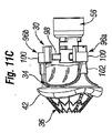
図6は、分解図であり、図7および8は、本発明の人工心臓弁を送達するための例示的なシステム50の組立図である。送達システム50の修正された構成要素も、図9および10に示されている。送達システム50は、その遠位端上のバルーン40と、近位端上の栓塞子54とを有するバルーンカテーテル52を含む。栓塞子54は、Y字付属品58のルアーコネクタまたは他のそのような固定具を受容する近位連結器56を提示する。前述のノーズコーン38は、カテーテル52の最遠位端に取り付いてもよいが、より好ましくは、バルーンカテーテル52の中心管腔を通して挿入されるワイヤ(図示せず)に取り付く。
FIG. 6 is an exploded view and FIGS. 7 and 8 are assembly views of an
カテーテル52およびノーズコーン38は、近位セクション62および遠位セクション64を有する中空ハンドル60を通過する。遠位ハンドルセクション64の遠位端は、弁ホルダ68のハブ66に堅く取り付き、それは次に、人工心臓弁構成要素30に取り付く。弁ホルダ68の詳細を、図11A−11Eを参照して以下で挙げる。
The
ハンドル60の2つのセクション62、64は、望ましくは、成形プラスチック等の剛体材料で形成され、その遠位端に取り付けられた人工弁構成要素30を操作するための比較的剛体の細長い管を形成するように相互に連結される。具体的には、遠位セクション64は、ホルダハブ66に容易に連結され、したがって、術前洗浄ステップ中に弁構成要素30を管理するための便利なツールを提供してもよい。この目的で、遠位セクション64は、ホルダハブ66に連結する遠位管状セグメント70と、近位ハンドルセクション62の管状延長部74を受容する開口部をその近位端に有する、拡大近位セグメント72とを特色とする。図6は、2つのセクションが係脱することを防止するように、摩擦締まり嵌めのために管状延長部74の外部上に提供されてもよい、Oリング76を示す。示されていないが、遠位管状セグメント70はまた、ホルダハブ66に堅く連結するためのOリングを有してもよく、または螺合あるいは同等物で取り付けられてもよい。1つの好ましい実施形態では、カテーテル52上のバルーン40は、保護および取り扱いやすさのために、近位ハンドルセクション62内に包装される。したがって、近位および遠位ハンドルセクション62、64を連結することにより、バルーンカテーテル52が、弁構成要素30につながる連続管腔を通して前進させられ得るように、システム50を「搭載」する。
The two
図9および10は、図7に示されたものと同様であるが、それぞれの受容開口の中に形成された相補的陥凹に嵌め込む、片持ち歯の形態である近位および遠位ハンドルセクション62、64の両方の上に代替的な連結具77を伴う、送達システム50を図示する。同様に、噛合部品上の螺合、ならびに他の同様の手段も使用することができる。図9は、弁構成要素の連結ステント36を拡張するように膨張させられたバルーン40を示す。
FIGS. 9 and 10 are similar to those shown in FIG. 7, but proximal and distal handles in the form of cantilever teeth that fit into complementary recesses formed in the respective receiving openings. The
好ましい実施形態では、人工弁構成要素30は、生体組織弁尖を組み込み、ホルダ68に取り付けられるが、他の導入システム50の構成要素とは別に包装および保管される。一般的には、生体組織が、長い保管期間にわたって、保存液を有する瓶の中に包装および保管される一方で、他の構成要素は、乾燥状態で包装および保管される。
In a preferred embodiment, the
図7−9に見られるように組み立てられると、細長い管腔(番号付けされていない)は、Y字付属品58の近位端からバルーン40の内部まで延在する。Y字付属品58は、望ましくは、吹送システムに取り付けるためのメスネジ式コネクタ80、またはルアー付属品84を有する側面ポート82を含み、または同様の手段がバルーン40の吹送に使用されてもよい。
When assembled as seen in FIGS. 7-9, an elongated lumen (not numbered) extends from the proximal end of the
図7および8は、ハンドル60およびその関連構造に対するカテーテル52および関連構造の2つの縦方向位置を示す。図7に示された後退位置では、バルーン40は、主に遠位ハンドルセクション64内に存在する。図7は、外科医が体外から標的弁輪に隣接する場所へ人工弁構成要素30を前進させる、導入システム50の送達構成を図示する。ノーズコーン38は、円錐形の未配備連結ステント36の遠位端の周囲に延在し、それを保護する。この構成は、図5Dにおいても見られるが、明確にするためにホルダ68が除去されている。近位連結器56とハンドル60の近位端との間の間隔Sに留意されたい。
Figures 7 and 8 show two longitudinal positions of the
図5A−5Hに関して上記で説明されたように、外科医は、弁輪におけるその所望の埋込み位置に人工弁構成要素30を前進させ、次いで、弁構成要素を通してバルーン40を前進させ、それを膨張させる。そうするために、連結ステント36からノーズコーン38を係脱するために、バルーンカテーテル40が矢印78によって示されるように遠位に変位された状態で、操作者は、図7の後退構成から図8の配備構成に送達システム50を変換する。近位連結器56がハンドル60の近位端に接触し、図7に示された空間Sを排除することに留意されたい。
As described above with respect to FIGS. 5A-5H, the surgeon advances the
人工弁構成要素30は、上記で説明されたように、配備前の基礎ステント24を伴って、または伴わずに、弁輪に埋め込まれてもよいことを理解されたい。連結ステント36は、基礎ステント24がない場合に、(弁尖切除術によって、またはよらずに)天然弁輪に対して弁構成要素30を固着するために十分頑丈であってもよい。その結果として、人工心臓弁を導入するためのシステム50の説明は、配備前の基礎ステント24を伴うか、または伴わない手術との関連で理解されるべきである。
It should be understood that the
送達システム50の動作のさらなる説明の前に、弁構成要素30および弁ホルダ68のより詳細な説明が必要である。図11A−11Eは、本発明の送達ホルダ68上に載置された例示的な弁構成要素30のいくつかの斜視図および他の図である。既述のように、弁構成要素30は、その流入端に取り付けられた連結ステント36を有する人工弁34を備える。好ましい実施形態では、人工弁34は、市販されている既製の拡張不可能で折畳み不可能な業務用人工弁を備える。連結ステント36を取り付けるために、任意の数の人工心臓弁が改造されることができ、したがって、本発明との関連で使用するために好適となり得る。例えば、人工弁34は、合成または生体である、機械的な弁または可撓性弁尖を伴う弁であってもよい。しかしながら、好ましい実施形態では、人工弁34は、生体組織弁尖86(図11A)を含む。さらに、上記のように、人工弁34は、望ましくは、Edwards Lifesciences(Irvine,California)から入手可能なCarpentier−Edwards PERIMOUNT Magna(登録商標)大動脈心臓弁(例えば、モデル3000TFX)である。
Before further description of the operation of
連結ステント36は、好ましくは、縫製輪の完全性を保存する方法において、製造過程中に弁の縫製輪42の心室(または流入)側面に取り付き、弁の有効開口面積(EOA)の縮小を防止する。望ましくは、連結ステント36は、縫製輪の外側輪郭を維持する態様で縫製輪42に連続的に縫合される。縫合糸は、ステント骨格の開口または小穴に、または次に骨格に縫い合わせられる布被膜に通過させられてもよい。他の接続の解決策は、ステントから内向きに延在する突起部またはフック、紐、マジックテープ(登録商標)、スナップ、接着剤等を含む。代替として、連結ステント36は、人工弁34内でより堅固に剛体構成要素に接続されてもよい。したがって、埋込み中に、外科医は、従来の手術に従って、弁輪に対して縫製輪42を設置することができる。これは、適正な患者・人工弁合致が達成されていることを確実にするために、外科医になじみのある触覚フィードバックを与える。また、弁輪の流出側に対する縫製輪42の配置は、心室に向かう弁構成要素30の移行の確率を低減することに役立つ。
The connecting
連結ステント36は、圧着前の先細りの316Lステンレス鋼バルーン拡張可能ステントであってもよく、望ましくは、いったん基礎ステント24内に埋め込まれると、弁傍漏出に対して密閉し、組織内方成長を推進することに役立つように、ポリエステルスカート88によって覆われる(図5F参照)。連結ステント36は、図11A−11Eの先細りの収縮形状と、図5Fおよび図10にも示された広口拡張形状との間で遷移する。
The linking
連結ステント36は、望ましくは、3つの略軸方向に延在する支柱92に接続された複数の鋸歯状のまたは別様に角度を成す、蛇行性またはウェブ状の支柱90を備える。以下で分かるように、支柱92は、望ましくは、一連の均等に離間した開口を特色とし、それに、ポリエステルスカート88を保持する縫合糸が固着されてもよい。図5Fにおいて最も良く見られるように、拡張された時のステント36は、外向きに広がって、基礎ステント24の内面に対して密接に一致し、基礎ステントと実質的に同じ軸長を有する。連結ステント36からの鉤または他の突出部等の固着デバイスが、連結ステントと基礎ステント24との間の摩擦保持を強化するように提供されてもよい。
The connecting
直線または曲線の支柱90を保有するかどうかにかかわらず、連結ステントの特定の構成は、必要に応じて修正されてもよいことを理解されたい。図12−17を参照して以下で説明されるように、多数のステント設計があり、そのうちのいずれかが、潜在的に好適であってもよい。同様に、好ましい実施形態は、バルーン拡張可能連結ステント36を組み込むが、自己拡張式ステントは、主に送達システムに対する、ある修正と代替することができる。当然ながら、同じ融通性および設計が基礎ステント24に該当する。好ましい実施形態では、基礎ステント24および連結ステント36の両方は、望ましくは、最初に、天然弁尖を伴うか、または伴わない弁輪に、次いで、2つのステントの間に、弁34に対するより堅固なアンカを提供するために、塑性的に拡張可能である。ステントは、下記で説明されるように、バルーンまたは機械的拡張器を使用して拡張されてもよい。
It should be understood that the particular configuration of the connecting stent may be modified as needed, whether or not it has straight or
依然として11A−11Eを参照すると、ホルダ68は、前述の近位ハブ66と、ホルダの中心部分を形成する、そのより細い遠位延長部94とを備える。中心延長部94の周囲で円周方向に等距離に離間し、そこから半径方向外向きに突出する3つの脚部96a、96b、96cは、内側支柱98と、外側交連静置部100とを備える。人工弁34は、好ましくは、流出方向に突出する、複数の、典型的には、3つの交連102を含む。示されていないが、交連静置部100は、好ましくは、交連102の先端が嵌合する窪みを組み込む。
Still referring to 11A-11E, the
一実施形態では、ホルダ68は、埋込み手技の可視性を増加させるために透明である、Delrinまたはポリプロピレン等の剛体ポリマーで形成される。図11Eにおいて最も良く見られるように、ホルダ68は、弁尖86の良好な可視性を外科医に提供するために、脚部96a、96b、96cの間に開口部を呈し、脚部の透明性は、可視性をさらに促進し、影を最小化するためにそれを通る光の透過を可能にする。本明細書で詳細に説明されていないが、図11Eはまた、人工弁34の織物を通して、かつ各脚部の切断ガイドを横断して、接続縫合糸が通過させられることを可能にする、脚部96a、96b、96cの中の一連の貫通穴も図示する。当技術分野で公知であるように、ホルダ68に接続され、弁を通過する中間の一本の縫合糸を切断することによって、所望されるときにホルダが弁から引き離されることを可能にする。
In one embodiment, the
図11Cおよび11Dは、支柱90および軸方向に延在する柱92がより良好に画定されている、図11Aおよび11Bに示されたものからいくらか修正された連結ステント36を図示する。具体的には、後者が、示された円錐形からより管状の構成に拡張する能力をステント36に提供するため、柱92は、支柱90よりもいくらか幅広くて頑丈である。また、略円形補強輪104が、弁縫製輪42に隣接する。柱92および輪104はさらに、縫合糸または同等物を使用して、ポリエステルスカート88をステント36に固定するために使用されてもよい、一連の貫通穴106を含む。連結ステント36のいくつかの変化例も以下で説明する。
FIGS. 11C and 11D illustrate a somewhat modified
図12A−12Bは、平坦構成(12A)および概して拡張形状である管状拡張構成(12B)の両方で例示的な連結ステント36を図示する。既述のように、ウェブ状支柱90および補強輪104は、3つの略軸方向に延在する柱92を接続する。複数の均等に離間した開口106は、適所にポリエステルスカート88(図11B参照)を保持するためのアンカを提供する。図示した実施形態では、ウェブ状支柱90はまた、一連の軸方向に延在する支柱108も含む。弁の縫製輪に接続し、補強輪104によって画定される連結ステント36の上端は、交互する弓状谷間110と頂点112とを有する起伏のある経路を辿る。図11Cから分かるように、例示的な人工弁34は、連結ステント36の上端が一致する、起伏のある縫製輪42を有する。好ましい実施形態では、ステント36の幾何学形状は、起伏のある縫製輪42の幾何学形状に合致する。当然ながら、人工弁の縫製輪が平面的である場合には、連結ステント36の上端も平面的になる。また、図12Bの管状変形は、拡張構成の例示であるが、バルーン40は、最終的にわずかに円錐形になるように、ステント36の自由(下)端を過剰に拡張してもよいことに留意されたい。
12A-12B illustrate an exemplary
図13Aおよび13Bは、再び、それぞれ平坦および管状構成で、代替的な連結ステント120を示す。第一の実施形態と同様に、連結ステント120は、一連の軸方向に延在する支柱124の間に延在する、ウェブ状支柱122を含む。この実施形態では、軸方向に延在する支柱124の全ては、実質的に同じ細い断面サイズである。ステント120の上端または接続端は、再び、補強輪126を含むが、この変形は、間隙によって分離された一連の短い長さで中断される。上端は、複数の交互する谷間128と頂点130とを画定し、補強輪126の長さが頂点を画定する。軸方向に延在する支柱124は、ステント120の上端の波形と一致しており、かつ頂点および谷間の中央と一致する。
FIGS. 13A and 13B again show an
補強輪126を構成する長さの間の間隙は、ステント120が、いくつかの異なるサイズの人工弁34と合致されることを可能にする。つまり、ステント120の大多数は、可変直径を有し、拡張可能であり、補強輪126に間隙を提供することにより、対応する縫製輪のサイズに合致するよう成形することができるように、上端も可変直径を有することを可能にする。これは、対応するサイズのステントがそれぞれの異なるサイズの弁に使用される必要がないため、製造費を削減する。
The gap between the lengths that make up the
図14は、一連の軸方向に延在する支柱136の間に接続されるウェブ状支柱134を含む、連結ステント120と極めて同様である、なおもさらに代替的な連結ステント132の平面図であり、上端は、一連の短い長さの支柱によって形成される補強輪138によって画定される。図13Aおよび13Bの実施形態とは対照的に、起伏のある上端の頂点は、支柱とは対照的な間隙を有する。これを表す別の方法としては、軸方向に延在する支柱136がステント132の上端の波形と不一致であり、頂点および谷間の中央に対応しない。
FIG. 14 is a plan view of a still further
図15は、軸方向に延在する支柱144と上部補強輪146との間に拡張可能支柱142を再び有する、例示的な連結ステント140を図示する。軸方向に延在する支柱144は、ステントの上端の頂点および谷間と一致している。補強輪146は、その周囲で連続的であるが、可変直径も有するため、前述のそのような輪の中間物である。つまり、輪146は、可変長のより細いブリッジ部分150によって接続される、固定長の一連の長さの支柱148を備える。ブリッジ部分150はそれぞれ、直線化する(引き延ばす)か、またはより屈曲(圧縮)することができるように、半径部分を伴って形成される。一連の開口152もステント142の上端に形成され、ステントを対応する人工弁の縫製輪に固定する時に、縫合糸または他の取付手段の固着点を提供する。
FIG. 15 illustrates an exemplary connecting
図16では、代替的な連結ステント154は、図15のステント140と同一であるが、軸方向に延在する支柱156は、起伏のある上端の頂点および谷間と不一致である。
In FIG. 16, an alternative connecting
図17は、軸方向に延在する支柱164を接続する一連の拡張可能支柱162を有する、連結ステント160のなおもさらなる変化例を示す。図12Aおよび12Bに示された変形と同様に、ウェブ状支柱162も一連の軸方向に延在する支柱166を含むが、これらは、主軸支柱164よりも細い。補強輪168はまた、ウェブ状支柱162よりも厚く、輪が不連続で拡張可能であるように、各谷間の1つ以上の間隙170を特色とする。軸方向に延在する支柱164、166の上の鉤172、174は、連結ステント160と、それが協働する基礎ステントとの間の保持を強化するために利用されてもよく、または、上記で説明されるように、基礎ステントがない状況では、環状組織とともに利用されてもよい。
FIG. 17 illustrates yet a further variation of the connecting
上記のように、本明細書で説明される2構成要素弁システムは、外側または基礎ステント(基礎ステント24等)と、内側または弁ステント(連結ステント36等)とを有する、弁構成要素を利用する。弁およびそのステントは、固着前の外側ステントの管腔の中へ前進し、弁ステントは、2つのステントを接合し、その埋込み位置に弁を固着するように拡張する。ステント間の後続の相対運動を最小化するように、内側ステントおよび外側ステントが、円周方向および軸方向の両方で正しく位置付けられることが重要である。実際に、大動脈弁置換術の主要な用途にとって、天然交連に対する弁の交連の円周位置が非常に重要である。弁構成要素に取り付く連結ステントのいくつかの変化例が、上記で示され、説明されている。図18−20は、例示的な基礎ステント、および2つのステント間の協働を図示する。 As described above, the two component valve system described herein utilizes a valve component having an outer or basal stent (such as basal stent 24) and an inner or valve stent (such as a connecting stent 36). To do. The valve and its stent are advanced into the lumen of the outer stent prior to anchoring and the valve stent joins the two stents and expands to anchor the valve in its implantation position. It is important that the inner and outer stents are properly positioned both circumferentially and axially so as to minimize subsequent relative movement between the stents. In fact, the circumferential position of the commissure of the valve relative to the natural commissure is very important for the main application of aortic valve replacement. Several variations of connecting stents that attach to the valve component have been shown and described above. 18-20 illustrate an exemplary basic stent and cooperation between the two stents.
図18Aおよび18Bは、複数の略軸方向に延在する支柱184の間に延在する複数の半径方向に拡張可能な支柱182を備える、基礎ステント180の例示的な実施形態を示す。図示した実施形態では、支柱182は、支柱184の間に山形パターンを形成するが、蛇行性またはダイヤモンド形等の他の構成も使用することができる。半径方向に拡張可能な支柱182の一番上および下の列は、複数の三角頂点186および谷間188を形成するよう、並列に配接される。軸方向支柱184は、谷間188と一致している。
FIGS. 18A and 18B show an exemplary embodiment of a
図18Aの平坦図は、それぞれ軸方向支柱184のうちの1つから上向きに延在する、4つの軸方向突起190を示す。4つの突起190が示されているが、例示的な基礎ステント180は、望ましくは、図18Bの管状変形の周囲で見られるように、3つの均等に円周方向に離間した突起を有し、基礎ステントに対する位置マーカーを提供する。したがって、これらのマーカーは、マーカーが天然交連と整合するように、外科医がステント180を配向しやすくする。さらに、弁構成要素が基礎ステント180内で前進するにつれて、可視的な突起190は、内側ステントを基礎ステント内で適正に配向することができるように、参照マークを提供する。この点に関して、突起190は、ステント180の他の部分とは違う色であってもよく、またはその上に放射線不透過性指標を有してもよい。
The top view of FIG. 18A shows four
中央の支柱182の上列より上側の突起190の長さはまた、外科医がステント180を軸方向に位置付けることに役立つように較正されてもよい。例えば、突起190の先端から天然弁輪の水平面までの距離を判定することができ、突起190は、冠状動脈口の水平面の直下等の特定の解剖学的ランドマークに位置することができる。
The length of the
図18Aの起伏のある鎖線192は、基礎ステント180上に重ね合わせられて透視状態で示される、内側または連結ステント140の上端を表す。そのようなものとして、鎖線192はまた、起伏のある縫製輪も表し、連結ステントの上端も平面的であるように、縫製輪が平面的となり得る反復を持つ。連結ステント140は、ステントの波形上端のそれぞれの頂点および谷間と一致している、軸方向に延在する支柱を含む。図示した組み合わせでは、連結ステント(鎖線192)の波形上端のピークは、突起190を有する軸方向支柱184と回転対応する(一致している)。したがって、連結ステント140の軸方向支柱は、その上端の頂点と一致しているため、基礎ステント180の軸方向支柱184とも一致している。逆に、連結ステントは、その上端の頂点と不一致である軸方向支柱を有してもよく、その場合、2つのステントのそれぞれの軸方向支柱も不一致である。
The undulating
図19は、概して、図18Aの基礎ステント180と同じ構成要素を有する、代替的な基礎ステント200を示すが、軸方向支柱184は、中央の支柱182の外側列の頂点186の間に延在する。以前の実施形態では、軸方向支柱184は、谷間188の間に延在する。図16の連結ステント154は、2つのステントの軸方向支柱が、その間の相互係止を増加させるように、どのように不一致であるかを図示するために、基礎ステント200上に重ね合わせられて透視状態で示されている。
FIG. 19 shows an
ステント200はまた、中央の支柱182の異なる列も呈する。具体的には、第一の列202aは、比較的浅い角度を有するV字を画定し、第2の列202bは、中間の角度を伴うV字を画定し、第3の列202cは、さらなる鋭角を伴うV字を画定する。これらの列の中の中央の支柱182によって形成される異なる角度は、拡張された時に、ステントを円錐形態に成形することに役立つ。つまり、人工弁から最も遠い、第3の列202cの中の支柱は、ステントの折畳み円錐形から拡張管状形状への遷移に適応するように、拡張に対して最大能力を有する。
当業者であれば、2つのステントの間の保持を増加させるための多くの方法があることを理解するであろう。例えば、2つのステント上のウェブ状の拡張可能支柱の頂点および谷間は、不一致または一致して配向することができる。好ましい実施形態では、2つのステントの頂点および谷間は、内側ステントの拡張が、その頂点を外側ステントの谷間の中へ外向きに変形させるように、不一致であり、それにより、その間に相互係止構造を提供する。上記で説明される変化例は、この協働のいくつかの置換を提供する。 One skilled in the art will appreciate that there are many ways to increase the retention between two stents. For example, the apexes and valleys of the web-like expandable struts on the two stents can be oriented inconsistent or coincident. In a preferred embodiment, the apexes and valleys of the two stents are mismatched so that the expansion of the inner stent deforms the apexes outwardly into the valleys of the outer stent, thereby interlocking therebetween. Provide structure. The variations described above provide some permutations of this cooperation.
加えて、ステントの一方または両方の上の軸方向突起は、他方のステントへの干渉を提供するように屈曲させることができる。例えば、図12Aに示されたステント36の中の軸方向支柱108の下端は、外側ステント内の空隙の中で延在するように、不均一な形状のバルーンの拡張によって外向きに屈曲させることができる。同様に、図17の実施形態は、対応する基礎ステントに干渉するように外向きに屈曲させることができる、鉤172、174を図示する。2つのステントの間の保持を増加させるように、1つの位置から別の位置に遷移する支柱端または鉤は、バルーンを用いて、または体内の設置時に自動形状変化を通して等、機械的屈曲によって作動させることができる。すなわち、室温で第一の形状を成し、体温で第二の形状を成すように、Nitinol等のいくつかの形状記憶合金を、温度変化時に形状変化を受けるように設計することができる。
In addition, axial protrusions on one or both of the stents can be bent to provide interference to the other stent. For example, the lower end of the
図20は、2つのステント間の保持を増加させるための単純化した手段を図示する。内側弁ステント210は、その下端214が外側ステントより下側に延在するように、外側基礎ステント212内に嵌合する。内側ステント210内のバルーンの過剰拡張により、下端214は、外側ステント内の内側ステントの相対上方移動を防止するように、外向きに屈曲または湾曲させられる。
FIG. 20 illustrates a simplified means for increasing the retention between two stents.
図21は、機械的拡張器224を用いて基礎ステント222を送達および拡張するためのデバイス220の斜視図である。図示した実施形態では、拡張器224は、その上で基礎ステント22が圧着される、複数の拡散型指部226を含む。デバイス220は、その内側でプランジャ232が直線的に摺動する、バレル230を含む、シリンジ様装置を含む。指部226は、軸方向に固定されるが、バレル230に対して枢動または屈曲することが可能である。プランジャ232の遠位端は、拡散型指部226の内面によって外接される直径よりも大きい外径を有する。好ましくは、バレル230に対するプランジャ232の遠位移動が、次第に外向きに指部にカム作用するように、指部226の内側に近位導入斜面がある。プランジャ232の2つの位置が、図21および23に示されている。
FIG. 21 is a perspective view of a
プランジャ232の単純な直線移動の代替案として、それはまた、バレル230内に螺合して受容されてもよい。なおもさらに、プランジャ232は、相互に対して自由に回転可能な2つの部品で形成されてもよく、近位部品が、バレル230内で螺合して受容される一方で、遠位部品は、バレルに対して回転せず、外向きに指部226にカム作用するのみである。なおもさらに、カム作用の代わりに、機械的結合が使用されてもよく、それにより、ともにヒンジ連結されたレバーが、指部226の外向き移動を生成する。さらに、バルーンの外側に載置された機械的部品を有する膨張性バルーンを使用する、ハイブリッド変形が利用されてもよい。当業者であれば、この機構の多数の変化例が可能であり、要点はバルーン拡張が唯一の媒介物ではないことを理解するであろう。
As an alternative to simple linear movement of the
望ましくは、指部226は、心臓弁輪により良好に嵌合する特定の形状に基礎ステント222を拡張するために、曲線を付けて作られた外形を有する。例えば、基礎ステント222は、より幅広い上下端、およびより小さい中央部を伴う、砂時計形に拡張されてもよく、および/または上端は、大動脈洞により良好に嵌合するように、3つの小葉形状を伴って形成されてもよい。後者の場合、3つの小葉形状は、埋込み時に基礎ステント222を配向するため、また、その内側で受容される弁構成要素の連結ステントを配向するためにも有用である。
Desirably, the
別の有利な特徴では、先行図に図示された2構成要素弁システムは、天然弁尖を除去した後に組織に縫合される置換弁と比較して、外科的手技の時間を大幅に削減するデバイスおよび方法を提供する。例えば、図5−9のステント24は、迅速に配備されてもよく、弁構成要素30も、迅速にステントに取り付けられてもよい。これは、体外循環に必要とされる時間を削減し、それにより、患者へのリスクを大幅に低減する。
In another advantageous feature, the two-component valve system illustrated in the preceding figure is a device that significantly reduces the time of a surgical procedure compared to a replacement valve that is sutured to tissue after removal of the native leaflet. And providing a method. For example, the
埋込み過程を加速することに加えて、その内側で弁およびそのステントが載置する、固着前のステントを有する本発明は、弁輪が、そうでなければ可能であるよりも大きい弁に適応するように拡張されることを可能にする。具体的には、臨床研究は、バルーン拡張可能ステントによって、左心室流出路(LVOT)を有意に拡張でき、依然として正常な機能を保持できることを示している。これに関連して、LVOTを「有意に拡張すること」は、少なくとも10%、より好ましくは10乃至30%の間でそれを拡張することを意味する。絶対項では、LVOTは、正常な開口サイズに応じて、1.5乃至5mm拡張されてもよい。この弁輪の拡張は、外科的に埋め込まれた人工弁のサイズを増加させる機会を生じる。本発明は、バルーン拡張可能基礎ステント、およびバルーン拡張可能弁ステントを採用する。これら2つのステントの組み合わせは、人工弁の流入端において、大動脈弁輪またはその直下でLVOTの拡張を可能にする。基礎ステントの外側とLVOTとの間で生成される締まり嵌めは、空間を占める綿撒糸または縫合糸を伴わずに弁を固定し、それにより、最大可能弁サイズの配置を可能にする。そうでなければ従来の手術で利用可能であるよりも大きい弁は、体積血流を増進し、弁を通る圧力勾配を低減する。 In addition to accelerating the implantation process, the present invention with a stent prior to anchoring, on which the valve and its stent rest, adapts to valves where the annulus is larger than otherwise possible Allows to be extended. Specifically, clinical studies have shown that balloon expandable stents can significantly expand the left ventricular outflow tract (LVOT) and still retain normal function. In this context, “significantly expanding” an LVOT means expanding it by at least 10%, more preferably between 10-30%. In absolute terms, the LVOT may be expanded 1.5 to 5 mm depending on the normal opening size. This expansion of the annulus creates an opportunity to increase the size of the surgically implanted prosthetic valve. The present invention employs a balloon expandable basic stent and a balloon expandable valve stent. The combination of these two stents enables LVOT expansion at or just below the aortic annulus at the inflow end of the prosthetic valve. The interference fit created between the outside of the base stent and the LVOT secures the valve without space-occupying pledgets or sutures, thereby allowing placement of the largest possible valve size. A valve that is otherwise larger than is available in conventional surgery increases volume blood flow and reduces the pressure gradient through the valve.
本発明の実施形態は、重要な新しいデバイスおよび方法を提供し、弁は、迅速かつ効率的に身体管腔にしっかりと固着され得ることが、当業者によって理解されるであろう。本発明の実施形態は、外科医が弁を組織に縫合する必要がなく、外科的手技によって人工弁を埋め込むための手段を提供する。したがって、外科的手技時間が大幅に減少させられる。さらに、弁に対する基礎ステントを提供することに加えて、ステントは、拡張状態で天然弁を維持するために使用されてもよい。結果として、外科医が天然弁尖を除去する必要がなく、それによって手技時間をさらに削減する。 It will be appreciated by those skilled in the art that embodiments of the present invention provide significant new devices and methods, and the valve can be fastened and secured to the body lumen quickly and efficiently. Embodiments of the present invention provide a means for implanting a prosthetic valve by a surgical procedure without requiring the surgeon to suture the valve to tissue. Thus, surgical procedure time is greatly reduced. Further, in addition to providing a base stent for the valve, the stent may be used to maintain the native valve in the expanded state. As a result, the surgeon does not need to remove the natural leaflets, thereby further reducing the procedure time.
また、本発明は、改良されたシステムを提供し、弁部材は、より迅速かつ効率的に置換され得ることも理解されるであろう。より具体的には、弁を除去するために、いずれの縫合糸も切断する必要はない。むしろ、弁部材は、ステント(または他の基礎ステント)から断絶され得、新しい弁部材がその場所に接続されてもよい。これは、生物組織弁または限定された設計寿命を有する他の弁を使用する場合に、重要な利点である。 It will also be appreciated that the present invention provides an improved system and that the valve member can be replaced more quickly and efficiently. More specifically, it is not necessary to cut any suture to remove the valve. Rather, the valve member may be disconnected from the stent (or other base stent) and a new valve member may be connected in place. This is an important advantage when using biological tissue valves or other valves with limited design life.
本発明を、その好ましい実施形態において説明してきたが、使用されてきた言葉は、限定ではなく説明の言葉であることを理解されたい。したがって、本発明の真の範囲から逸脱することなく、添付の特許請求の範囲内において変更が行われてもよい。 Although the present invention has been described in its preferred embodiments, it is to be understood that the language used has been described rather than limiting. Accordingly, changes may be made within the scope of the appended claims without departing from the true scope of the invention.
Claims (19)
拡張不可能で折畳み不可能な人工弁を含む弁構成要素であって、該弁構成要素は、自身の流入端から延在する拡張可能連結ステントをさらに含み、該連結ステントは、埋込み位置への送達のための収縮状態と、心臓弁輪への外向きの接続のために構成される拡張状態とを有する、弁構成要素
を備える、人工心臓弁システム。 An artificial heart valve system,
A valve component comprising an unexpandable and non-foldable prosthetic valve , the valve component further including an expandable connecting stent extending from its inflow end, wherein the connecting stent is in an implanted position. and a contracted state for delivery, and a configured expanded state for outbound connections to the heart valve annulus, a valve arrangement elements, prosthetic heart valve system.
拡張不可能で折畳み不可能な人工弁を含む弁構成要素であって、該弁構成要素は、自身の流入端から延在する拡張可能な連結ステントをさらに含み、該連結ステントは、埋込み位置への送達のための収縮状態と、心臓弁輪への外向きの接続のために構成される拡張状態とを有する、弁構成要素
を備え、
該弁構成要素は、該輪に隣接する埋込み位置まで、収縮状態にある該連結ステントとともに前進させられるように構成されており、
該連結ステントは、該輪と接触した状態で、それに接続される該拡張状態まで拡張されるようにさらに構成されている、システム。 Delivering a prosthetic heart valve system, and a system of embedding Mutame,
A valve arrangement elements containing non-expandable in the folded non prosthetic valve, valve component further comprises an expandable coupling stent extending from the inlet end of itself the connecting stent embedded position and a contracted state for delivery to, and a configured expanded state for outbound connections to the heart valve annulus, valve component
With
Valve components, to the buried position adjacent to the wheel is configured to be advanced together with the coupling stent in a collapsed state,
The linking stent in contact with the wheel, and is further configured to be extended to the expanded state of being connected thereto, the system.
該ホルダは、ハンドルの遠位端に載置され、該ハンドルは自身を通る管腔を有し、
前記システムは、該ハンドルの管腔および該ホルダを通過させられるように構成され、かつ、該弁構成要素内にあるバルーンカテーテルをさらに含み、
バルーンは、該バルーンカテーテル上で膨張させられて、前記連結ステントを拡張するように構成されている、請求項7に記載のシステム。 The valve element includes a proximal hub, are placed on the holder and a lumen therethrough,
The holder is mounted on the distal end of the handle, the handle will have a lumen therethrough,
The system further includes a balloon catheter configured to be passed through the handle lumen and the holder and within the valve component ;
The balloon is inflated on the balloon catheter, the being configured to extend the coupling stent of claim 7 system.
拡張不可能で折畳み不可能な人工弁を含む弁構成要素であって、該弁構成要素は、自身の流入端から延在する拡張可能な連結ステントをさらに含み、該連結ステントは、埋込み位置への送達のための収縮状態と、拡張状態とを有する、弁構成要素と、
該弁構成要素に接続される弁ホルダと、
バルーンを有するバルーンカテーテルと、
該弁ホルダの近位端に取り付くように構成され、該カテーテルの通過のための管腔を有するハンドルであって、該バルーンは、該ハンドルを通り、該ホルダを越え、該弁構成要素を通って遠位に延在する、ハンドルと
を備える、システム。 A system for delivering a prosthetic heart valve,
A valve component including an unexpandable and non-foldable prosthetic valve , the valve component further including an expandable connecting stent extending from its inflow end, wherein the connecting stent is in an implanted position. A valve component having a contracted state and an expanded state for delivery of
A valve holder which is connected to the valve arrangement elements,
A balloon catheter having a balloon;
A handle configured to attach to a proximal end of the valve holder and having a lumen for passage of the catheter, the balloon passing through the handle, over the holder and through the valve component And a handle extending distally.
Applications Claiming Priority (5)
| Application Number | Priority Date | Filing Date | Title |
|---|---|---|---|
| US13939808P | 2008-12-19 | 2008-12-19 | |
| US61/139,398 | 2008-12-19 | ||
| US12/635,471 | 2009-12-10 | ||
| US12/635,471 US8308798B2 (en) | 2008-12-19 | 2009-12-10 | Quick-connect prosthetic heart valve and methods |
| PCT/US2009/068693 WO2010080594A2 (en) | 2008-12-19 | 2009-12-18 | Quick-connect prosthetic heart valve and methods |
Related Child Applications (1)
| Application Number | Title | Priority Date | Filing Date |
|---|---|---|---|
| JP2014044778A Division JP2014166358A (en) | 2008-12-19 | 2014-03-07 | Quick-connect prosthetic heart valve and methods |
Publications (3)
| Publication Number | Publication Date |
|---|---|
| JP2012512718A JP2012512718A (en) | 2012-06-07 |
| JP2012512718A5 JP2012512718A5 (en) | 2013-01-17 |
| JP5498508B2 true JP5498508B2 (en) | 2014-05-21 |
Family
ID=42267224
Family Applications (2)
| Application Number | Title | Priority Date | Filing Date |
|---|---|---|---|
| JP2011542476A Active JP5498508B2 (en) | 2008-12-19 | 2009-12-18 | Quick connect prosthetic heart valve and method |
| JP2014044778A Pending JP2014166358A (en) | 2008-12-19 | 2014-03-07 | Quick-connect prosthetic heart valve and methods |
Family Applications After (1)
| Application Number | Title | Priority Date | Filing Date |
|---|---|---|---|
| JP2014044778A Pending JP2014166358A (en) | 2008-12-19 | 2014-03-07 | Quick-connect prosthetic heart valve and methods |
Country Status (10)
| Country | Link |
|---|---|
| US (7) | US8308798B2 (en) |
| EP (4) | EP3290004B1 (en) |
| JP (2) | JP5498508B2 (en) |
| CN (2) | CN104068947B (en) |
| AU (2) | AU2009335700B2 (en) |
| BR (1) | BRPI0923190A2 (en) |
| CA (2) | CA2966311C (en) |
| ES (1) | ES2880016T3 (en) |
| HK (1) | HK1202043A1 (en) |
| WO (1) | WO2010080594A2 (en) |
Families Citing this family (381)
| Publication number | Priority date | Publication date | Assignee | Title |
|---|---|---|---|---|
| CA2419811A1 (en) | 2000-08-18 | 2002-02-28 | Atritech, Inc. | Expandable implant devices for filtering blood flow from atrial appendages |
| WO2004030568A2 (en) * | 2002-10-01 | 2004-04-15 | Ample Medical, Inc. | Device and method for repairing a native heart valve leaflet |
| US8308797B2 (en) | 2002-01-04 | 2012-11-13 | Colibri Heart Valve, LLC | Percutaneously implantable replacement heart valve device and method of making same |
| US9579194B2 (en) * | 2003-10-06 | 2017-02-28 | Medtronic ATS Medical, Inc. | Anchoring structure with concave landing zone |
| US8840663B2 (en) | 2003-12-23 | 2014-09-23 | Sadra Medical, Inc. | Repositionable heart valve method |
| US20120041550A1 (en) | 2003-12-23 | 2012-02-16 | Sadra Medical, Inc. | Methods and Apparatus for Endovascular Heart Valve Replacement Comprising Tissue Grasping Elements |
| US8052749B2 (en) | 2003-12-23 | 2011-11-08 | Sadra Medical, Inc. | Methods and apparatus for endovascular heart valve replacement comprising tissue grasping elements |
| US8603160B2 (en) | 2003-12-23 | 2013-12-10 | Sadra Medical, Inc. | Method of using a retrievable heart valve anchor with a sheath |
| US8579962B2 (en) | 2003-12-23 | 2013-11-12 | Sadra Medical, Inc. | Methods and apparatus for performing valvuloplasty |
| US7988724B2 (en) | 2003-12-23 | 2011-08-02 | Sadra Medical, Inc. | Systems and methods for delivering a medical implant |
| US7381219B2 (en) | 2003-12-23 | 2008-06-03 | Sadra Medical, Inc. | Low profile heart valve and delivery system |
| US7780725B2 (en) | 2004-06-16 | 2010-08-24 | Sadra Medical, Inc. | Everting heart valve |
| US11278398B2 (en) | 2003-12-23 | 2022-03-22 | Boston Scientific Scimed, Inc. | Methods and apparatus for endovascular heart valve replacement comprising tissue grasping elements |
| US20050137687A1 (en) | 2003-12-23 | 2005-06-23 | Sadra Medical | Heart valve anchor and method |
| US7959666B2 (en) * | 2003-12-23 | 2011-06-14 | Sadra Medical, Inc. | Methods and apparatus for endovascularly replacing a heart valve |
| US8343213B2 (en) | 2003-12-23 | 2013-01-01 | Sadra Medical, Inc. | Leaflet engagement elements and methods for use thereof |
| US9526609B2 (en) | 2003-12-23 | 2016-12-27 | Boston Scientific Scimed, Inc. | Methods and apparatus for endovascularly replacing a patient's heart valve |
| DE102005003632A1 (en) | 2005-01-20 | 2006-08-17 | Fraunhofer-Gesellschaft zur Förderung der angewandten Forschung e.V. | Catheter for the transvascular implantation of heart valve prostheses |
| JP4912395B2 (en) | 2005-05-24 | 2012-04-11 | エドワーズ ライフサイエンシーズ コーポレイション | Rapid placement prosthetic heart valve |
| US7780723B2 (en) | 2005-06-13 | 2010-08-24 | Edwards Lifesciences Corporation | Heart valve delivery system |
| US20070213813A1 (en) | 2005-12-22 | 2007-09-13 | Symetis Sa | Stent-valves for valve replacement and associated methods and systems for surgery |
| US9867530B2 (en) | 2006-08-14 | 2018-01-16 | Volcano Corporation | Telescopic side port catheter device with imaging system and method for accessing side branch occlusions |
| WO2010004546A1 (en) | 2008-06-16 | 2010-01-14 | Valtech Cardio, Ltd. | Annuloplasty devices and methods of delivery therefor |
| US9883943B2 (en) | 2006-12-05 | 2018-02-06 | Valtech Cardio, Ltd. | Implantation of repair devices in the heart |
| US7896915B2 (en) | 2007-04-13 | 2011-03-01 | Jenavalve Technology, Inc. | Medical device for treating a heart valve insufficiency |
| WO2009009802A1 (en) | 2007-07-12 | 2009-01-15 | Volcano Corporation | Oct-ivus catheter for concurrent luminal imaging |
| US9596993B2 (en) | 2007-07-12 | 2017-03-21 | Volcano Corporation | Automatic calibration systems and methods of use |
| JP5524835B2 (en) | 2007-07-12 | 2014-06-18 | ヴォルカノ コーポレイション | In vivo imaging catheter |
| EP3443938B1 (en) | 2007-09-26 | 2024-01-24 | St. Jude Medical, LLC | Collapsible prosthetic heart valves |
| US9532868B2 (en) | 2007-09-28 | 2017-01-03 | St. Jude Medical, Inc. | Collapsible-expandable prosthetic heart valves with structures for clamping native tissue |
| EP2254512B1 (en) * | 2008-01-24 | 2016-01-06 | Medtronic, Inc. | Markers for prosthetic heart valves |
| US9044318B2 (en) | 2008-02-26 | 2015-06-02 | Jenavalve Technology Gmbh | Stent for the positioning and anchoring of a valvular prosthesis |
| ES2903231T3 (en) | 2008-02-26 | 2022-03-31 | Jenavalve Tech Inc | Stent for positioning and anchoring a valve prosthesis at an implantation site in a patient's heart |
| US9061119B2 (en) * | 2008-05-09 | 2015-06-23 | Edwards Lifesciences Corporation | Low profile delivery system for transcatheter heart valve |
| ES2616743T3 (en) | 2008-07-15 | 2017-06-14 | St. Jude Medical, Llc | Collapsible and re-expandable prosthetic heart valve sleeve designs and complementary technological applications |
| US8652202B2 (en) | 2008-08-22 | 2014-02-18 | Edwards Lifesciences Corporation | Prosthetic heart valve and delivery apparatus |
| EP2901966B1 (en) | 2008-09-29 | 2016-06-29 | Edwards Lifesciences CardiAQ LLC | Heart valve |
| WO2010040009A1 (en) | 2008-10-01 | 2010-04-08 | Cardiaq Valve Technologies, Inc. | Delivery system for vascular implant |
| EP2340075B1 (en) | 2008-10-10 | 2013-03-06 | Sadra Medical, Inc. | Medical devices and delivery systems for delivering medical devices |
| US8137398B2 (en) * | 2008-10-13 | 2012-03-20 | Medtronic Ventor Technologies Ltd | Prosthetic valve having tapered tip when compressed for delivery |
| US8470013B2 (en) * | 2008-10-20 | 2013-06-25 | Imds Corporation | Systems and methods for aneurysm treatment and vessel occlusion |
| US8591567B2 (en) | 2008-11-25 | 2013-11-26 | Edwards Lifesciences Corporation | Apparatus and method for in situ expansion of prosthetic device |
| US8308798B2 (en) | 2008-12-19 | 2012-11-13 | Edwards Lifesciences Corporation | Quick-connect prosthetic heart valve and methods |
| US10517719B2 (en) | 2008-12-22 | 2019-12-31 | Valtech Cardio, Ltd. | Implantation of repair devices in the heart |
| BRPI1008902A2 (en) | 2009-02-27 | 2016-03-15 | St Jude Medical | prosthetic heart valve. |
| CN101919752B (en) * | 2009-03-30 | 2014-04-09 | 苏州杰成医疗科技有限公司 | Valve prosthesis with movably attached claspers with apex |
| US8414644B2 (en) | 2009-04-15 | 2013-04-09 | Cardiaq Valve Technologies, Inc. | Vascular implant and delivery system |
| US8348998B2 (en) | 2009-06-26 | 2013-01-08 | Edwards Lifesciences Corporation | Unitary quick connect prosthetic heart valve and deployment system and methods |
| US9180007B2 (en) | 2009-10-29 | 2015-11-10 | Valtech Cardio, Ltd. | Apparatus and method for guide-wire based advancement of an adjustable implant |
| US8870950B2 (en) | 2009-12-08 | 2014-10-28 | Mitral Tech Ltd. | Rotation-based anchoring of an implant |
| US10433956B2 (en) * | 2010-02-24 | 2019-10-08 | Medtronic Ventor Technologies Ltd. | Mitral prosthesis and methods for implantation |
| AU2013204420B2 (en) * | 2010-03-01 | 2014-07-31 | Colibri Heart Valve Llc | Percutaneously deliverable heart valve and methods associated therewith |
| WO2011109450A2 (en) | 2010-03-01 | 2011-09-09 | Colibri Heart Valve Llc | Percutaneously deliverable heart valve and methods associated therewith |
| US20110224785A1 (en) | 2010-03-10 | 2011-09-15 | Hacohen Gil | Prosthetic mitral valve with tissue anchors |
| EP3581151B1 (en) | 2010-04-21 | 2021-03-10 | Medtronic, Inc. | Prosthetic valve with sealing members |
| US8579964B2 (en) | 2010-05-05 | 2013-11-12 | Neovasc Inc. | Transcatheter mitral valve prosthesis |
| ES2861100T3 (en) | 2010-05-10 | 2021-10-05 | Edwards Lifesciences Corp | Prosthetic heart valve |
| CN103002833B (en) | 2010-05-25 | 2016-05-11 | 耶拿阀门科技公司 | Artificial heart valve and comprise artificial heart valve and support through conduit carry interior prosthese |
| CN103153384B (en) | 2010-06-28 | 2016-03-09 | 科利柏心脏瓣膜有限责任公司 | For the device of device in the delivery of vascular of chamber |
| DK2590595T3 (en) | 2010-07-09 | 2015-12-07 | Highlife Sas | Transcatheter atrioventricular heart valve prosthesis |
| US11653910B2 (en) | 2010-07-21 | 2023-05-23 | Cardiovalve Ltd. | Helical anchor implantation |
| US9132009B2 (en) | 2010-07-21 | 2015-09-15 | Mitraltech Ltd. | Guide wires with commissural anchors to advance a prosthetic valve |
| US8992604B2 (en) | 2010-07-21 | 2015-03-31 | Mitraltech Ltd. | Techniques for percutaneous mitral valve replacement and sealing |
| US9763657B2 (en) | 2010-07-21 | 2017-09-19 | Mitraltech Ltd. | Techniques for percutaneous mitral valve replacement and sealing |
| CA2809909A1 (en) * | 2010-09-01 | 2012-03-08 | Julie A. Logan | Cardiac valve support structure |
| US10105224B2 (en) | 2010-09-01 | 2018-10-23 | Mvalve Technologies Ltd. | Cardiac valve support structure |
| US9125741B2 (en) | 2010-09-10 | 2015-09-08 | Edwards Lifesciences Corporation | Systems and methods for ensuring safe and rapid deployment of prosthetic heart valves |
| US9370418B2 (en) | 2010-09-10 | 2016-06-21 | Edwards Lifesciences Corporation | Rapidly deployable surgical heart valves |
| US8641757B2 (en) * | 2010-09-10 | 2014-02-04 | Edwards Lifesciences Corporation | Systems for rapidly deploying surgical heart valves |
| CN103108611B (en) | 2010-09-10 | 2016-08-31 | 西美蒂斯股份公司 | Valve replacement device |
| US9579193B2 (en) | 2010-09-23 | 2017-02-28 | Transmural Systems Llc | Methods and systems for delivering prostheses using rail techniques |
| US10321998B2 (en) | 2010-09-23 | 2019-06-18 | Transmural Systems Llc | Methods and systems for delivering prostheses using rail techniques |
| US8845720B2 (en) | 2010-09-27 | 2014-09-30 | Edwards Lifesciences Corporation | Prosthetic heart valve frame with flexible commissures |
| CA2820738C (en) | 2010-12-14 | 2019-01-15 | Colibri Heart Valve Llc | Percutaneously deliverable heart valve including folded membrane cusps with integral leaflets |
| US9498317B2 (en) * | 2010-12-16 | 2016-11-22 | Edwards Lifesciences Corporation | Prosthetic heart valve delivery systems and packaging |
| EP2654624B1 (en) | 2010-12-23 | 2023-10-04 | Twelve, Inc. | System for mitral valve repair and replacement |
| US11141063B2 (en) | 2010-12-23 | 2021-10-12 | Philips Image Guided Therapy Corporation | Integrated system architectures and methods of use |
| US11040140B2 (en) | 2010-12-31 | 2021-06-22 | Philips Image Guided Therapy Corporation | Deep vein thrombosis therapeutic methods |
| CA2824284C (en) | 2011-01-17 | 2020-10-27 | Novita Therapeutics, Llc | Ballstent device and methods of use |
| US11484318B2 (en) | 2011-01-17 | 2022-11-01 | Artio Medical, Inc. | Expandable body device and method of use |
| US8888843B2 (en) | 2011-01-28 | 2014-11-18 | Middle Peak Medical, Inc. | Device, system, and method for transcatheter treatment of valve regurgitation |
| US8845717B2 (en) | 2011-01-28 | 2014-09-30 | Middle Park Medical, Inc. | Coaptation enhancement implant, system, and method |
| US9155619B2 (en) | 2011-02-25 | 2015-10-13 | Edwards Lifesciences Corporation | Prosthetic heart valve delivery apparatus |
| WO2012127309A1 (en) | 2011-03-21 | 2012-09-27 | Ontorfano Matteo | Disk-based valve apparatus and method for the treatment of valve dysfunction |
| US9308087B2 (en) | 2011-04-28 | 2016-04-12 | Neovasc Tiara Inc. | Sequentially deployed transcatheter mitral valve prosthesis |
| US9554897B2 (en) | 2011-04-28 | 2017-01-31 | Neovasc Tiara Inc. | Methods and apparatus for engaging a valve prosthesis with tissue |
| EP2520251A1 (en) | 2011-05-05 | 2012-11-07 | Symetis SA | Method and Apparatus for Compressing Stent-Valves |
| US20120283705A1 (en) * | 2011-05-05 | 2012-11-08 | Medtronic, Inc. | Percutaneous delivery tool |
| CA2840084C (en) | 2011-06-21 | 2019-11-05 | Foundry Newco Xii, Inc. | Prosthetic heart valve devices and associated systems and methods |
| EP2731550B1 (en) | 2011-07-12 | 2016-02-24 | Boston Scientific Scimed, Inc. | Coupling system for a replacement valve |
| WO2013021374A2 (en) | 2011-08-05 | 2013-02-14 | Mitraltech Ltd. | Techniques for percutaneous mitral valve replacement and sealing |
| US20140324164A1 (en) | 2011-08-05 | 2014-10-30 | Mitraltech Ltd. | Techniques for percutaneous mitral valve replacement and sealing |
| US8852272B2 (en) * | 2011-08-05 | 2014-10-07 | Mitraltech Ltd. | Techniques for percutaneous mitral valve replacement and sealing |
| WO2013021375A2 (en) | 2011-08-05 | 2013-02-14 | Mitraltech Ltd. | Percutaneous mitral valve replacement and sealing |
| WO2013033592A1 (en) | 2011-08-31 | 2013-03-07 | Volcano Corporation | Optical-electrical rotary joint and methods of use |
| US9549817B2 (en) | 2011-09-22 | 2017-01-24 | Transmural Systems Llc | Devices, systems and methods for repairing lumenal systems |
| EA201400478A1 (en) | 2011-10-19 | 2014-10-30 | Твелв, Инк. | DEVICES, SYSTEMS AND METHODS OF PROTESIZING THE HEART VALVE |
| US9763780B2 (en) | 2011-10-19 | 2017-09-19 | Twelve, Inc. | Devices, systems and methods for heart valve replacement |
| EA201400481A1 (en) | 2011-10-19 | 2014-10-30 | Твелв, Инк. | ARTIFICIAL HEART VALVE DEVICES, ARTIFICIAL MITRAL VALVES AND RELATED SYSTEMS AND METHODS |
| US9655722B2 (en) | 2011-10-19 | 2017-05-23 | Twelve, Inc. | Prosthetic heart valve devices, prosthetic mitral valves and associated systems and methods |
| US9039757B2 (en) | 2011-10-19 | 2015-05-26 | Twelve, Inc. | Prosthetic heart valve devices, prosthetic mitral valves and associated systems and methods |
| US11202704B2 (en) | 2011-10-19 | 2021-12-21 | Twelve, Inc. | Prosthetic heart valve devices, prosthetic mitral valves and associated systems and methods |
| US8951243B2 (en) | 2011-12-03 | 2015-02-10 | Boston Scientific Scimed, Inc. | Medical device handle |
| US9078747B2 (en) | 2011-12-21 | 2015-07-14 | Edwards Lifesciences Corporation | Anchoring device for replacing or repairing a heart valve |
| WO2013112547A1 (en) | 2012-01-25 | 2013-08-01 | Boston Scientific Scimed, Inc. | Valve assembly with a bioabsorbable gasket and a replaceable valve implant |
| US9579198B2 (en) | 2012-03-01 | 2017-02-28 | Twelve, Inc. | Hydraulic delivery systems for prosthetic heart valve devices and associated methods |
| US9427315B2 (en) | 2012-04-19 | 2016-08-30 | Caisson Interventional, LLC | Valve replacement systems and methods |
| US9011515B2 (en) | 2012-04-19 | 2015-04-21 | Caisson Interventional, LLC | Heart valve assembly systems and methods |
| US9345573B2 (en) | 2012-05-30 | 2016-05-24 | Neovasc Tiara Inc. | Methods and apparatus for loading a prosthesis onto a delivery system |
| US9883941B2 (en) | 2012-06-19 | 2018-02-06 | Boston Scientific Scimed, Inc. | Replacement heart valve |
| CN103655004B (en) * | 2012-09-21 | 2015-11-25 | 上海微创医疗器械(集团)有限公司 | Implant delivery system |
| US9324141B2 (en) | 2012-10-05 | 2016-04-26 | Volcano Corporation | Removal of A-scan streaking artifact |
| US10070827B2 (en) | 2012-10-05 | 2018-09-11 | Volcano Corporation | Automatic image playback |
| JP2015532536A (en) | 2012-10-05 | 2015-11-09 | デイビッド ウェルフォード, | System and method for amplifying light |
| US11272845B2 (en) | 2012-10-05 | 2022-03-15 | Philips Image Guided Therapy Corporation | System and method for instant and automatic border detection |
| US10568586B2 (en) | 2012-10-05 | 2020-02-25 | Volcano Corporation | Systems for indicating parameters in an imaging data set and methods of use |
| US9286673B2 (en) | 2012-10-05 | 2016-03-15 | Volcano Corporation | Systems for correcting distortions in a medical image and methods of use thereof |
| US9858668B2 (en) | 2012-10-05 | 2018-01-02 | Volcano Corporation | Guidewire artifact removal in images |
| US9307926B2 (en) | 2012-10-05 | 2016-04-12 | Volcano Corporation | Automatic stent detection |
| US9367965B2 (en) | 2012-10-05 | 2016-06-14 | Volcano Corporation | Systems and methods for generating images of tissue |
| US9292918B2 (en) | 2012-10-05 | 2016-03-22 | Volcano Corporation | Methods and systems for transforming luminal images |
| US9840734B2 (en) | 2012-10-22 | 2017-12-12 | Raindance Technologies, Inc. | Methods for analyzing DNA |
| WO2014064695A2 (en) | 2012-10-23 | 2014-05-01 | Valtech Cardio, Ltd. | Percutaneous tissue anchor techniques |
| US8628571B1 (en) | 2012-11-13 | 2014-01-14 | Mitraltech Ltd. | Percutaneously-deliverable mechanical valve |
| US9433521B2 (en) | 2012-11-27 | 2016-09-06 | Medtronic, Inc. | Distal tip for a delivery catheter |
| WO2014093374A1 (en) | 2012-12-13 | 2014-06-19 | Volcano Corporation | Devices, systems, and methods for targeted cannulation |
| US10939826B2 (en) | 2012-12-20 | 2021-03-09 | Philips Image Guided Therapy Corporation | Aspirating and removing biological material |
| US10942022B2 (en) | 2012-12-20 | 2021-03-09 | Philips Image Guided Therapy Corporation | Manual calibration of imaging system |
| JP2016506276A (en) | 2012-12-20 | 2016-03-03 | ジェレミー スティガール, | Locate the intravascular image |
| US11406498B2 (en) | 2012-12-20 | 2022-08-09 | Philips Image Guided Therapy Corporation | Implant delivery system and implants |
| CA2895502A1 (en) | 2012-12-20 | 2014-06-26 | Jeremy Stigall | Smooth transition catheters |
| EP2934310A4 (en) | 2012-12-20 | 2016-10-12 | Nathaniel J Kemp | Optical coherence tomography system that is reconfigurable between different imaging modes |
| US9486143B2 (en) | 2012-12-21 | 2016-11-08 | Volcano Corporation | Intravascular forward imaging device |
| US9383263B2 (en) | 2012-12-21 | 2016-07-05 | Volcano Corporation | Systems and methods for narrowing a wavelength emission of light |
| US10413317B2 (en) | 2012-12-21 | 2019-09-17 | Volcano Corporation | System and method for catheter steering and operation |
| US10191220B2 (en) | 2012-12-21 | 2019-01-29 | Volcano Corporation | Power-efficient optical circuit |
| US10993694B2 (en) | 2012-12-21 | 2021-05-04 | Philips Image Guided Therapy Corporation | Rotational ultrasound imaging catheter with extended catheter body telescope |
| EP2936426B1 (en) | 2012-12-21 | 2021-10-13 | Jason Spencer | System and method for graphical processing of medical data |
| CA2895940A1 (en) | 2012-12-21 | 2014-06-26 | Andrew Hancock | System and method for multipath processing of image signals |
| WO2014099760A1 (en) | 2012-12-21 | 2014-06-26 | Mai Jerome | Ultrasound imaging with variable line density |
| US10058284B2 (en) | 2012-12-21 | 2018-08-28 | Volcano Corporation | Simultaneous imaging, monitoring, and therapy |
| US9612105B2 (en) | 2012-12-21 | 2017-04-04 | Volcano Corporation | Polarization sensitive optical coherence tomography system |
| CN104884002B (en) | 2012-12-31 | 2017-04-05 | 爱德华兹生命科学公司 | The Surgical heart valve expanded after being suitable for implantation into |
| US20140200662A1 (en) * | 2013-01-16 | 2014-07-17 | Mvalve Technologies Ltd. | Anchoring elements for intracardiac devices |
| US9681952B2 (en) | 2013-01-24 | 2017-06-20 | Mitraltech Ltd. | Anchoring of prosthetic valve supports |
| WO2014138555A1 (en) | 2013-03-07 | 2014-09-12 | Bernhard Sturm | Multimodal segmentation in intravascular images |
| US10226597B2 (en) | 2013-03-07 | 2019-03-12 | Volcano Corporation | Guidewire with centering mechanism |
| US10583002B2 (en) | 2013-03-11 | 2020-03-10 | Neovasc Tiara Inc. | Prosthetic valve with anti-pivoting mechanism |
| US9119713B2 (en) * | 2013-03-11 | 2015-09-01 | St. Jude Medical, Cardiology Division, Inc. | Transcatheter valve replacement |
| US9867697B2 (en) | 2013-03-12 | 2018-01-16 | St. Jude Medical, Cardiology Division, Inc. | Self-actuating sealing portions for a paravalvular leak protection |
| US9398951B2 (en) | 2013-03-12 | 2016-07-26 | St. Jude Medical, Cardiology Division, Inc. | Self-actuating sealing portions for paravalvular leak protection |
| US11154313B2 (en) | 2013-03-12 | 2021-10-26 | The Volcano Corporation | Vibrating guidewire torquer and methods of use |
| US10271949B2 (en) | 2013-03-12 | 2019-04-30 | St. Jude Medical, Cardiology Division, Inc. | Paravalvular leak occlusion device for self-expanding heart valves |
| US9339274B2 (en) | 2013-03-12 | 2016-05-17 | St. Jude Medical, Cardiology Division, Inc. | Paravalvular leak occlusion device for self-expanding heart valves |
| US10638939B2 (en) | 2013-03-12 | 2020-05-05 | Philips Image Guided Therapy Corporation | Systems and methods for diagnosing coronary microvascular disease |
| WO2014164832A1 (en) | 2013-03-12 | 2014-10-09 | Edwards Lifesciences Corporation | Rapidly deployable surgical heart valves |
| SG11201506279VA (en) | 2013-03-12 | 2015-09-29 | Edwards Lifesciences Corp | Systems and methods for ensuring safe and rapid deployment of prosthetic heart valves |
| US9301687B2 (en) | 2013-03-13 | 2016-04-05 | Volcano Corporation | System and method for OCT depth calibration |
| US11026591B2 (en) | 2013-03-13 | 2021-06-08 | Philips Image Guided Therapy Corporation | Intravascular pressure sensor calibration |
| US10561509B2 (en) | 2013-03-13 | 2020-02-18 | DePuy Synthes Products, Inc. | Braided stent with expansion ring and method of delivery |
| EP2967488B1 (en) | 2013-03-13 | 2021-06-16 | Jinhyoung Park | System for producing an image from a rotational intravascular ultrasound device |
| WO2014152365A2 (en) | 2013-03-14 | 2014-09-25 | Volcano Corporation | Filters with echogenic characteristics |
| US10292677B2 (en) | 2013-03-14 | 2019-05-21 | Volcano Corporation | Endoluminal filter having enhanced echogenic properties |
| US9326856B2 (en) | 2013-03-14 | 2016-05-03 | St. Jude Medical, Cardiology Division, Inc. | Cuff configurations for prosthetic heart valve |
| US10219887B2 (en) | 2013-03-14 | 2019-03-05 | Volcano Corporation | Filters with echogenic characteristics |
| US9681951B2 (en) | 2013-03-14 | 2017-06-20 | Edwards Lifesciences Cardiaq Llc | Prosthesis with outer skirt and anchors |
| AR095586A1 (en) * | 2013-03-15 | 2015-10-28 | Novita Therapeutics Llc | EXPANSIBLE BODY DEVICE AND METHOD OF USE |
| CN103190968B (en) | 2013-03-18 | 2015-06-17 | 杭州启明医疗器械有限公司 | Bracket and stably-mounted artificial valve displacement device with same |
| US9572665B2 (en) | 2013-04-04 | 2017-02-21 | Neovasc Tiara Inc. | Methods and apparatus for delivering a prosthetic valve to a beating heart |
| US10111747B2 (en) | 2013-05-20 | 2018-10-30 | Twelve, Inc. | Implantable heart valve devices, mitral valve repair devices and associated systems and methods |
| US9468527B2 (en) | 2013-06-12 | 2016-10-18 | Edwards Lifesciences Corporation | Cardiac implant with integrated suture fasteners |
| WO2014204807A1 (en) | 2013-06-19 | 2014-12-24 | Aga Medical Corporation | Collapsible valve having paravalvular leak protection |
| US8870948B1 (en) | 2013-07-17 | 2014-10-28 | Cephea Valve Technologies, Inc. | System and method for cardiac valve repair and replacement |
| US9919137B2 (en) | 2013-08-28 | 2018-03-20 | Edwards Lifesciences Corporation | Integrated balloon catheter inflation system |
| US9867694B2 (en) | 2013-08-30 | 2018-01-16 | Jenavalve Technology Inc. | Radially collapsible frame for a prosthetic valve and method for manufacturing such a frame |
| WO2015038458A1 (en) | 2013-09-12 | 2015-03-19 | St. Jude Medical, Cardiology Division, Inc. | Stent designs for prosthetic heart valves |
| US9421094B2 (en) | 2013-10-23 | 2016-08-23 | Caisson Interventional, LLC | Methods and systems for heart valve therapy |
| US10646333B2 (en) * | 2013-10-24 | 2020-05-12 | Medtronic, Inc. | Two-piece valve prosthesis with anchor stent and valve component |
| US10166098B2 (en) | 2013-10-25 | 2019-01-01 | Middle Peak Medical, Inc. | Systems and methods for transcatheter treatment of valve regurgitation |
| EP2870946B1 (en) | 2013-11-06 | 2018-10-31 | St. Jude Medical, Cardiology Division, Inc. | Paravalvular leak sealing mechanism |
| US9913715B2 (en) | 2013-11-06 | 2018-03-13 | St. Jude Medical, Cardiology Division, Inc. | Paravalvular leak sealing mechanism |
| US9700409B2 (en) | 2013-11-06 | 2017-07-11 | St. Jude Medical, Cardiology Division, Inc. | Reduced profile prosthetic heart valve |
| WO2015077274A1 (en) | 2013-11-19 | 2015-05-28 | St. Jude Medical, Cardiology Division, Inc. | Sealing structures for paravalvular leak protection |
| US20150209141A1 (en) | 2014-01-24 | 2015-07-30 | St. Jude Medical, Cardiology Division, Inc. | Stationary intra-annular halo designs for paravalvular leak (pvl) reduction-passive channel filling cuff designs |
| US9820852B2 (en) | 2014-01-24 | 2017-11-21 | St. Jude Medical, Cardiology Division, Inc. | Stationary intra-annular halo designs for paravalvular leak (PVL) reduction—active channel filling cuff designs |
| WO2015126712A1 (en) | 2014-02-18 | 2015-08-27 | St. Jude Medical, Cardiology Division, Inc. | Bowed runners for paravalvular leak protection |
| BR102014006114B1 (en) * | 2014-03-14 | 2022-05-10 | Antônio Francisco Neves Filho | Mechanical or biological heart valve stent for minimally invasive valve replacement procedure and stent delivery device |
| WO2015148241A1 (en) | 2014-03-26 | 2015-10-01 | St. Jude Medical, Cardiology Division, Inc. | Transcatheter mitral valve stent frames |
| US20170014115A1 (en) | 2014-03-27 | 2017-01-19 | Transmural Systems Llc | Devices and methods for closure of transvascular or transcameral access ports |
| EP3125826B1 (en) | 2014-03-31 | 2020-10-07 | St. Jude Medical, Cardiology Division, Inc. | Paravalvular sealing via extended cuff mechanisms |
| US9585752B2 (en) | 2014-04-30 | 2017-03-07 | Edwards Lifesciences Corporation | Holder and deployment system for surgical heart valves |
| EP3142604B1 (en) | 2014-05-16 | 2024-01-10 | St. Jude Medical, Cardiology Division, Inc. | Transcatheter valve with paravalvular leak sealing ring |
| WO2015175524A1 (en) | 2014-05-16 | 2015-11-19 | St. Jude Medical, Cardiology Division, Inc. | Subannular sealing for paravalvular leak protection |
| EP3257473A1 (en) | 2014-05-16 | 2017-12-20 | St. Jude Medical, Cardiology Division, Inc. | Stent assembly for use in prosthetic heart valves |
| US9974647B2 (en) | 2014-06-12 | 2018-05-22 | Caisson Interventional, LLC | Two stage anchor and mitral valve assembly |
| CA2958061A1 (en) | 2014-06-18 | 2015-12-23 | Middle Peak Medical, Inc. | Mitral valve implants for the treatment of valvular regurgitation |
| ES2914153T3 (en) * | 2014-06-24 | 2022-06-07 | Polares Medical Inc | Systems to anchor an implant |
| WO2016016899A1 (en) | 2014-07-30 | 2016-02-04 | Mitraltech Ltd. | Articulatable prosthetic valve |
| US10206796B2 (en) | 2014-08-27 | 2019-02-19 | DePuy Synthes Products, Inc. | Multi-strand implant with enhanced radiopacity |
| WO2016044647A2 (en) | 2014-09-17 | 2016-03-24 | Metactive Medical, Inc. | Expandable body device and method of use |
| AU2015335808B2 (en) * | 2014-10-23 | 2020-08-06 | Caisson Interventional, LLC | Systems and methods for heart valve therapy |
| US9750607B2 (en) | 2014-10-23 | 2017-09-05 | Caisson Interventional, LLC | Systems and methods for heart valve therapy |
| US9750605B2 (en) | 2014-10-23 | 2017-09-05 | Caisson Interventional, LLC | Systems and methods for heart valve therapy |
| US9901445B2 (en) | 2014-11-21 | 2018-02-27 | Boston Scientific Scimed, Inc. | Valve locking mechanism |
| EP3028668A1 (en) * | 2014-12-05 | 2016-06-08 | Nvt Ag | Prosthetic heart valve system and delivery system therefor |
| US10869755B2 (en) | 2014-12-09 | 2020-12-22 | Cephea Valve Technologies, Inc. | Replacement cardiac valves and methods of use and manufacture |
| WO2016115375A1 (en) | 2015-01-16 | 2016-07-21 | Boston Scientific Scimed, Inc. | Displacement based lock and release mechanism |
| US9861477B2 (en) | 2015-01-26 | 2018-01-09 | Boston Scientific Scimed Inc. | Prosthetic heart valve square leaflet-leaflet stitch |
| US10201417B2 (en) | 2015-02-03 | 2019-02-12 | Boston Scientific Scimed Inc. | Prosthetic heart valve having tubular seal |
| US9788942B2 (en) | 2015-02-03 | 2017-10-17 | Boston Scientific Scimed Inc. | Prosthetic heart valve having tubular seal |
| CA3162308A1 (en) | 2015-02-05 | 2016-08-11 | Cardiovalve Ltd. | Prosthetic valve with axially-sliding frames |
| US9974651B2 (en) | 2015-02-05 | 2018-05-22 | Mitral Tech Ltd. | Prosthetic valve with axially-sliding frames |
| US10231834B2 (en) * | 2015-02-09 | 2019-03-19 | Edwards Lifesciences Corporation | Low profile transseptal catheter and implant system for minimally invasive valve procedure |
| US10426617B2 (en) | 2015-03-06 | 2019-10-01 | Boston Scientific Scimed, Inc. | Low profile valve locking mechanism and commissure assembly |
| US10285809B2 (en) | 2015-03-06 | 2019-05-14 | Boston Scientific Scimed Inc. | TAVI anchoring assist device |
| US10080652B2 (en) | 2015-03-13 | 2018-09-25 | Boston Scientific Scimed, Inc. | Prosthetic heart valve having an improved tubular seal |
| CN107613908B (en) | 2015-03-19 | 2020-03-10 | 凯森因特万逊奈尔有限公司 | Systems and methods for heart valve therapy |
| EP3273911A1 (en) | 2015-03-24 | 2018-01-31 | St. Jude Medical, Cardiology Division, Inc. | Prosthetic mitral valve |
| CN107530168B (en) | 2015-05-01 | 2020-06-09 | 耶拿阀门科技股份有限公司 | Device and method with reduced pacemaker ratio in heart valve replacement |
| EP3294220B1 (en) | 2015-05-14 | 2023-12-06 | Cephea Valve Technologies, Inc. | Cardiac valve delivery devices and systems |
| EP3294221B1 (en) | 2015-05-14 | 2024-03-06 | Cephea Valve Technologies, Inc. | Replacement mitral valves |
| US10195392B2 (en) | 2015-07-02 | 2019-02-05 | Boston Scientific Scimed, Inc. | Clip-on catheter |
| WO2017004377A1 (en) | 2015-07-02 | 2017-01-05 | Boston Scientific Scimed, Inc. | Adjustable nosecone |
| EP3316822B1 (en) * | 2015-07-02 | 2020-12-09 | Edwards Lifesciences Corporation | Hybrid heart valves adapted for post-implant expansion |
| US10456246B2 (en) | 2015-07-02 | 2019-10-29 | Edwards Lifesciences Corporation | Integrated hybrid heart valves |
| US10179041B2 (en) | 2015-08-12 | 2019-01-15 | Boston Scientific Scimed Icn. | Pinless release mechanism |
| US10136991B2 (en) | 2015-08-12 | 2018-11-27 | Boston Scientific Scimed Inc. | Replacement heart valve implant |
| US10179046B2 (en) | 2015-08-14 | 2019-01-15 | Edwards Lifesciences Corporation | Gripping and pushing device for medical instrument |
| CN111658234B (en) | 2015-08-21 | 2023-03-10 | 托尔福公司 | Implantable heart valve devices, mitral valve repair devices, and associated systems and methods |
| US10034747B2 (en) | 2015-08-27 | 2018-07-31 | Medtronic Vascular, Inc. | Prosthetic valve system having a docking component and a prosthetic valve component |
| US20170056215A1 (en) | 2015-09-01 | 2017-03-02 | Medtronic, Inc. | Stent assemblies including passages to provide blood flow to coronary arteries and methods of delivering and deploying such stent assemblies |
| WO2017041029A1 (en) | 2015-09-02 | 2017-03-09 | Edwards Lifesciences Corporation | Spacer for securing a transcatheter valve to bioprosthetic cardiac structure |
| WO2017049003A1 (en) | 2015-09-15 | 2017-03-23 | Nasser Rafiee | Devices and methods for effectuating percutaneous glenn and fontan procedures |
| US9592121B1 (en) | 2015-11-06 | 2017-03-14 | Middle Peak Medical, Inc. | Device, system, and method for transcatheter treatment of valvular regurgitation |
| US10321996B2 (en) | 2015-11-11 | 2019-06-18 | Edwards Lifesciences Corporation | Prosthetic valve delivery apparatus having clutch mechanism |
| US9931204B2 (en) * | 2015-12-10 | 2018-04-03 | Medtronic, Inc. | Transcatheter heart valve replacement systems, heart valve prostheses, and methods for percutaneous heart valve replacement |
| US10265166B2 (en) | 2015-12-30 | 2019-04-23 | Caisson Interventional, LLC | Systems and methods for heart valve therapy |
| DE202017007326U1 (en) | 2016-01-29 | 2020-10-20 | Neovasc Tiara Inc. | Valve prosthesis to prevent flow obstruction |
| US10342660B2 (en) | 2016-02-02 | 2019-07-09 | Boston Scientific Inc. | Tensioned sheathing aids |
| US10531866B2 (en) | 2016-02-16 | 2020-01-14 | Cardiovalve Ltd. | Techniques for providing a replacement valve and transseptal communication |
| US10799677B2 (en) | 2016-03-21 | 2020-10-13 | Edwards Lifesciences Corporation | Multi-direction steerable handles for steering catheters |
| US10799676B2 (en) | 2016-03-21 | 2020-10-13 | Edwards Lifesciences Corporation | Multi-direction steerable handles for steering catheters |
| US11219746B2 (en) | 2016-03-21 | 2022-01-11 | Edwards Lifesciences Corporation | Multi-direction steerable handles for steering catheters |
| WO2017189276A1 (en) | 2016-04-29 | 2017-11-02 | Medtronic Vascular Inc. | Prosthetic heart valve devices with tethered anchors and associated systems and methods |
| WO2017195125A1 (en) | 2016-05-13 | 2017-11-16 | Jenavalve Technology, Inc. | Heart valve prosthesis delivery system and method for delivery of heart valve prosthesis with introducer sheath and loading system |
| US10583005B2 (en) | 2016-05-13 | 2020-03-10 | Boston Scientific Scimed, Inc. | Medical device handle |
| US10201416B2 (en) | 2016-05-16 | 2019-02-12 | Boston Scientific Scimed, Inc. | Replacement heart valve implant with invertible leaflets |
| US10456245B2 (en) | 2016-05-16 | 2019-10-29 | Edwards Lifesciences Corporation | System and method for applying material to a stent |
| EP3471665B1 (en) | 2016-06-17 | 2023-10-11 | Cephea Valve Technologies, Inc. | Cardiac valve delivery devices |
| US10588745B2 (en) | 2016-06-20 | 2020-03-17 | Medtronic Vascular, Inc. | Modular valve prosthesis, delivery system, and method of delivering and deploying a modular valve prosthesis |
| GB201613219D0 (en) | 2016-08-01 | 2016-09-14 | Mitraltech Ltd | Minimally-invasive delivery systems |
| USD800908S1 (en) | 2016-08-10 | 2017-10-24 | Mitraltech Ltd. | Prosthetic valve element |
| US10856975B2 (en) | 2016-08-10 | 2020-12-08 | Cardiovalve Ltd. | Prosthetic valve with concentric frames |
| US10383725B2 (en) | 2016-08-11 | 2019-08-20 | 4C Medical Technologies, Inc. | Heart chamber prosthetic valve implant with base, mesh and dome sections with single chamber anchoring for preservation, supplementation and/or replacement of native valve function |
| US10076428B2 (en) | 2016-08-25 | 2018-09-18 | DePuy Synthes Products, Inc. | Expansion ring for a braided stent |
| WO2018039543A1 (en) | 2016-08-26 | 2018-03-01 | St. Jude Medical, Cardiology Division, Inc. | Prosthetic heart valve with paravalvular leak mitigation features |
| US10575946B2 (en) | 2016-09-01 | 2020-03-03 | Medtronic Vascular, Inc. | Heart valve prosthesis and separate support flange for attachment thereto |
| EP3512466B1 (en) | 2016-09-15 | 2020-07-29 | St. Jude Medical, Cardiology Division, Inc. | Prosthetic heart valve with paravalvular leak mitigation features |
| US10292851B2 (en) | 2016-09-30 | 2019-05-21 | DePuy Synthes Products, Inc. | Self-expanding device delivery apparatus with dual function bump |
| US10182927B2 (en) * | 2016-10-21 | 2019-01-22 | DePuy Synthes Products, Inc. | Expansion ring for a braided stent |
| WO2018081490A1 (en) | 2016-10-28 | 2018-05-03 | St. Jude Medical, Cardiology Division, Inc. | Prosthetic mitral valve |
| EP3541462A4 (en) | 2016-11-21 | 2020-06-17 | Neovasc Tiara Inc. | Methods and systems for rapid retraction of a transcatheter heart valve delivery system |
| USD846122S1 (en) | 2016-12-16 | 2019-04-16 | Edwards Lifesciences Corporation | Heart valve sizer |
| US10653523B2 (en) | 2017-01-19 | 2020-05-19 | 4C Medical Technologies, Inc. | Systems, methods and devices for delivery systems, methods and devices for implanting prosthetic heart valves |
| EP4209196A1 (en) | 2017-01-23 | 2023-07-12 | Cephea Valve Technologies, Inc. | Replacement mitral valves |
| CN110621260B (en) | 2017-01-23 | 2022-11-25 | 科菲瓣膜技术有限公司 | Replacement mitral valve |
| US10561495B2 (en) * | 2017-01-24 | 2020-02-18 | 4C Medical Technologies, Inc. | Systems, methods and devices for two-step delivery and implantation of prosthetic heart valve |
| CN110392557A (en) | 2017-01-27 | 2019-10-29 | 耶拿阀门科技股份有限公司 | Heart valve simulation |
| US10478303B2 (en) | 2017-03-13 | 2019-11-19 | Polares Medical Inc. | Device, system, and method for transcatheter treatment of valvular regurgitation |
| US10653524B2 (en) | 2017-03-13 | 2020-05-19 | Polares Medical Inc. | Device, system, and method for transcatheter treatment of valvular regurgitation |
| JP7159230B2 (en) | 2017-03-13 | 2022-10-24 | ポラレス・メディカル・インコーポレイテッド | Devices, systems and methods for transcatheter treatment of valvular regurgitation |
| US11224511B2 (en) | 2017-04-18 | 2022-01-18 | Edwards Lifesciences Corporation | Heart valve sealing devices and delivery devices therefor |
| US10433961B2 (en) | 2017-04-18 | 2019-10-08 | Twelve, Inc. | Delivery systems with tethers for prosthetic heart valve devices and associated methods |
| US10575950B2 (en) | 2017-04-18 | 2020-03-03 | Twelve, Inc. | Hydraulic systems for delivering prosthetic heart valve devices and associated methods |
| DK3682854T3 (en) | 2017-04-18 | 2022-02-14 | Edwards Lifesciences Corp | Heart valve sealing devices and supply devices therefor |
| US10702378B2 (en) | 2017-04-18 | 2020-07-07 | Twelve, Inc. | Prosthetic heart valve device and associated systems and methods |
| US10973634B2 (en) | 2017-04-26 | 2021-04-13 | Edwards Lifesciences Corporation | Delivery apparatus for a prosthetic heart valve |
| US10959846B2 (en) | 2017-05-10 | 2021-03-30 | Edwards Lifesciences Corporation | Mitral valve spacer device |
| US10792151B2 (en) | 2017-05-11 | 2020-10-06 | Twelve, Inc. | Delivery systems for delivering prosthetic heart valve devices and associated methods |
| USD875250S1 (en) | 2017-05-15 | 2020-02-11 | St. Jude Medical, Cardiology Division, Inc. | Stent having tapered aortic struts |
| USD875935S1 (en) | 2017-05-15 | 2020-02-18 | St. Jude Medical, Cardiology Division, Inc. | Stent having tapered struts |
| USD889653S1 (en) | 2017-05-15 | 2020-07-07 | St. Jude Medical, Cardiology Division, Inc. | Stent having tapered struts |
| US10646338B2 (en) | 2017-06-02 | 2020-05-12 | Twelve, Inc. | Delivery systems with telescoping capsules for deploying prosthetic heart valve devices and associated methods |
| US10709591B2 (en) | 2017-06-06 | 2020-07-14 | Twelve, Inc. | Crimping device and method for loading stents and prosthetic heart valves |
| AU2018280236A1 (en) | 2017-06-07 | 2020-01-16 | Shifamed Holdings, Llc | Intravascular fluid movement devices, systems, and methods of use |
| EP3634311A1 (en) | 2017-06-08 | 2020-04-15 | Boston Scientific Scimed, Inc. | Heart valve implant commissure support structure |
| CN110996853B (en) | 2017-06-30 | 2023-01-10 | 爱德华兹生命科学公司 | Docking station for transcatheter valve |
| WO2019006332A1 (en) | 2017-06-30 | 2019-01-03 | Edwards Lifesciences Corporation | Lock and release mechanisms for trans-catheter implantable devices |
| US10786352B2 (en) | 2017-07-06 | 2020-09-29 | Twelve, Inc. | Prosthetic heart valve devices and associated systems and methods |
| US10729541B2 (en) | 2017-07-06 | 2020-08-04 | Twelve, Inc. | Prosthetic heart valve devices and associated systems and methods |
| US10857334B2 (en) | 2017-07-12 | 2020-12-08 | Edwards Lifesciences Corporation | Reduced operation force inflator |
| US10765503B2 (en) * | 2017-07-31 | 2020-09-08 | Edwards Lifesciences Corporation | Bicuspid valve dissection device |
| US10898325B2 (en) | 2017-08-01 | 2021-01-26 | Boston Scientific Scimed, Inc. | Medical implant locking mechanism |
| US11666444B2 (en) * | 2017-08-03 | 2023-06-06 | The Regents Of The University Of California | Atrial cage for placement, securing and anchoring of atrioventricular valves |
| US10575948B2 (en) | 2017-08-03 | 2020-03-03 | Cardiovalve Ltd. | Prosthetic heart valve |
| US10537426B2 (en) | 2017-08-03 | 2020-01-21 | Cardiovalve Ltd. | Prosthetic heart valve |
| US11246704B2 (en) | 2017-08-03 | 2022-02-15 | Cardiovalve Ltd. | Prosthetic heart valve |
| US10888421B2 (en) | 2017-09-19 | 2021-01-12 | Cardiovalve Ltd. | Prosthetic heart valve with pouch |
| US11793633B2 (en) | 2017-08-03 | 2023-10-24 | Cardiovalve Ltd. | Prosthetic heart valve |
| WO2019035966A1 (en) | 2017-08-16 | 2019-02-21 | Boston Scientific Scimed, Inc. | Replacement heart valve commissure assembly |
| US10806573B2 (en) | 2017-08-22 | 2020-10-20 | Edwards Lifesciences Corporation | Gear drive mechanism for heart valve delivery apparatus |
| WO2019036810A1 (en) | 2017-08-25 | 2019-02-28 | Neovasc Tiara Inc. | Sequentially deployed transcatheter mitral valve prosthesis |
| US11051939B2 (en) | 2017-08-31 | 2021-07-06 | Edwards Lifesciences Corporation | Active introducer sheath system |
| WO2019051476A1 (en) | 2017-09-11 | 2019-03-14 | Incubar, LLC | Conduit vascular implant sealing device for reducing endoleak |
| US11337803B2 (en) | 2017-09-19 | 2022-05-24 | Cardiovalve Ltd. | Prosthetic valve with inner and outer frames connected at a location of tissue anchor portion |
| EP3459469A1 (en) | 2017-09-23 | 2019-03-27 | Universität Zürich | Medical occluder device |
| HUE17881282T1 (en) * | 2017-09-28 | 2022-05-28 | Meril Life Sciences Pvt Ltd | Prosthetic valve |
| IL273562B2 (en) | 2017-10-18 | 2024-01-01 | Edwards Lifesciences Corp | Catheter assembly |
| US9895226B1 (en) | 2017-10-19 | 2018-02-20 | Mitral Tech Ltd. | Techniques for use with prosthetic valve leaflets |
| US11207499B2 (en) | 2017-10-20 | 2021-12-28 | Edwards Lifesciences Corporation | Steerable catheter |
| US11382751B2 (en) | 2017-10-24 | 2022-07-12 | St. Jude Medical, Cardiology Division, Inc. | Self-expandable filler for mitigating paravalvular leak |
| JP7319266B2 (en) | 2017-11-13 | 2023-08-01 | シファメド・ホールディングス・エルエルシー | Intravascular fluid transfer devices, systems and methods of use |
| GB201720803D0 (en) | 2017-12-13 | 2018-01-24 | Mitraltech Ltd | Prosthetic Valve and delivery tool therefor |
| GB201800399D0 (en) | 2018-01-10 | 2018-02-21 | Mitraltech Ltd | Temperature-control during crimping of an implant |
| JP7047106B2 (en) | 2018-01-19 | 2022-04-04 | ボストン サイエンティフィック サイムド,インコーポレイテッド | Medical device delivery system with feedback loop |
| EP3740160A2 (en) | 2018-01-19 | 2020-11-25 | Boston Scientific Scimed Inc. | Inductance mode deployment sensors for transcatheter valve system |
| EP3743016A1 (en) | 2018-01-23 | 2020-12-02 | Edwards Lifesciences Corporation | Prosthetic valve holders, systems, and methods |
| EP3720390B1 (en) | 2018-01-25 | 2024-05-01 | Edwards Lifesciences Corporation | Delivery system for aided replacement valve recapture and repositioning post- deployment |
| CN112004563A (en) | 2018-02-01 | 2020-11-27 | 施菲姆德控股有限责任公司 | Intravascular blood pump and methods of use and manufacture |
| WO2019157156A1 (en) | 2018-02-07 | 2019-08-15 | Boston Scientific Scimed, Inc. | Medical device delivery system with alignment feature |
| WO2019165394A1 (en) | 2018-02-26 | 2019-08-29 | Boston Scientific Scimed, Inc. | Embedded radiopaque marker in adaptive seal |
| US11813413B2 (en) | 2018-03-27 | 2023-11-14 | St. Jude Medical, Cardiology Division, Inc. | Radiopaque outer cuff for transcatheter valve |
| WO2019195860A2 (en) | 2018-04-04 | 2019-10-10 | Vdyne, Llc | Devices and methods for anchoring transcatheter heart valve |
| US11690997B2 (en) | 2018-04-06 | 2023-07-04 | Puzzle Medical Devices Inc. | Mammalian body conduit intralumenal device and lumen wall anchor assembly, components thereof and methods of implantation and explanation thereof |
| US11291570B2 (en) | 2018-04-27 | 2022-04-05 | Cook Medical Technologies Llc | Hybrid stent and delivery system |
| WO2019222367A1 (en) | 2018-05-15 | 2019-11-21 | Boston Scientific Scimed, Inc. | Replacement heart valve commissure assembly |
| US11844914B2 (en) | 2018-06-05 | 2023-12-19 | Edwards Lifesciences Corporation | Removable volume indicator for syringe |
| US11241310B2 (en) | 2018-06-13 | 2022-02-08 | Boston Scientific Scimed, Inc. | Replacement heart valve delivery device |
| USD908874S1 (en) | 2018-07-11 | 2021-01-26 | Edwards Lifesciences Corporation | Collapsible heart valve sizer |
| CN108703823A (en) * | 2018-07-27 | 2018-10-26 | 武汉开阖同立医疗科技有限公司 | A kind of insertion type Puffer-type sacculus aortic valve stent system |
| AU2019204522A1 (en) | 2018-07-30 | 2020-02-13 | DePuy Synthes Products, Inc. | Systems and methods of manufacturing and using an expansion ring |
| US10278848B1 (en) | 2018-08-06 | 2019-05-07 | DePuy Synthes Products, Inc. | Stent delivery with expansion assisting delivery wire |
| US11857441B2 (en) | 2018-09-04 | 2024-01-02 | 4C Medical Technologies, Inc. | Stent loading device |
| US10779946B2 (en) | 2018-09-17 | 2020-09-22 | Cardiovalve Ltd. | Leaflet-testing apparatus |
| US11284996B2 (en) | 2018-09-20 | 2022-03-29 | St. Jude Medical, Cardiology Division, Inc. | Attachment of leaflets to prosthetic heart valve |
| US10595994B1 (en) | 2018-09-20 | 2020-03-24 | Vdyne, Llc | Side-delivered transcatheter heart valve replacement |
| US11071627B2 (en) | 2018-10-18 | 2021-07-27 | Vdyne, Inc. | Orthogonally delivered transcatheter heart valve frame for valve in valve prosthesis |
| US11278437B2 (en) | 2018-12-08 | 2022-03-22 | Vdyne, Inc. | Compression capable annular frames for side delivery of transcatheter heart valve replacement |
| US10321995B1 (en) | 2018-09-20 | 2019-06-18 | Vdyne, Llc | Orthogonally delivered transcatheter heart valve replacement |
| US11344413B2 (en) | 2018-09-20 | 2022-05-31 | Vdyne, Inc. | Transcatheter deliverable prosthetic heart valves and methods of delivery |
| US11364117B2 (en) | 2018-10-15 | 2022-06-21 | St. Jude Medical, Cardiology Division, Inc. | Braid connections for prosthetic heart valves |
| CN112867468A (en) * | 2018-10-19 | 2021-05-28 | 爱德华兹生命科学公司 | Prosthetic heart valve with non-cylindrical frame |
| US11109969B2 (en) | 2018-10-22 | 2021-09-07 | Vdyne, Inc. | Guidewire delivery of transcatheter heart valve |
| US11779728B2 (en) | 2018-11-01 | 2023-10-10 | Edwards Lifesciences Corporation | Introducer sheath with expandable introducer |
| CA3118599A1 (en) | 2018-11-08 | 2020-05-14 | Neovasc Tiara Inc. | Ventricular deployment of a transcatheter mitral valve prosthesis |
| US11241312B2 (en) | 2018-12-10 | 2022-02-08 | Boston Scientific Scimed, Inc. | Medical device delivery system including a resistance member |
| US11471277B2 (en) | 2018-12-10 | 2022-10-18 | St. Jude Medical, Cardiology Division, Inc. | Prosthetic tricuspid valve replacement design |
| US11253359B2 (en) | 2018-12-20 | 2022-02-22 | Vdyne, Inc. | Proximal tab for side-delivered transcatheter heart valves and methods of delivery |
| WO2020139542A1 (en) | 2018-12-26 | 2020-07-02 | St. Jude Medical, Cardiology Division, Inc. | Elevated outer cuff for reducing paravalvular leakage and increasing stent fatigue life |
| US11039944B2 (en) | 2018-12-27 | 2021-06-22 | DePuy Synthes Products, Inc. | Braided stent system with one or more expansion rings |
| CN113507902A (en) * | 2019-01-17 | 2021-10-15 | 爱德华兹生命科学公司 | Frame for prosthetic heart valve |
| US11185409B2 (en) | 2019-01-26 | 2021-11-30 | Vdyne, Inc. | Collapsible inner flow control component for side-delivered transcatheter heart valve prosthesis |
| US11273032B2 (en) | 2019-01-26 | 2022-03-15 | Vdyne, Inc. | Collapsible inner flow control component for side-deliverable transcatheter heart valve prosthesis |
| CN113543750A (en) | 2019-03-05 | 2021-10-22 | 维迪内股份有限公司 | Tricuspid valve regurgitation control apparatus for orthogonal transcatheter heart valve prosthesis |
| US11076956B2 (en) | 2019-03-14 | 2021-08-03 | Vdyne, Inc. | Proximal, distal, and anterior anchoring tabs for side-delivered transcatheter mitral valve prosthesis |
| US11173027B2 (en) | 2019-03-14 | 2021-11-16 | Vdyne, Inc. | Side-deliverable transcatheter prosthetic valves and methods for delivering and anchoring the same |
| CN109938879A (en) * | 2019-03-19 | 2019-06-28 | 上海欣吉特生物科技有限公司 | A kind of surgical valve and its implanted device |
| EP3946163A4 (en) | 2019-04-01 | 2022-12-21 | Neovasc Tiara Inc. | Controllably deployable prosthetic valve |
| AU2020271896B2 (en) | 2019-04-10 | 2022-10-13 | Neovasc Tiara Inc. | Prosthetic valve with natural blood flow |
| JP2022530764A (en) | 2019-05-04 | 2022-07-01 | ブイダイン,インコーポレイテッド | Tightening device and method for deploying a laterally delivered artificial heart valve with a native annulus. |
| US11439504B2 (en) | 2019-05-10 | 2022-09-13 | Boston Scientific Scimed, Inc. | Replacement heart valve with improved cusp washout and reduced loading |
| EP3972673A4 (en) | 2019-05-20 | 2023-06-07 | Neovasc Tiara Inc. | Introducer with hemostasis mechanism |
| AU2020295566B2 (en) | 2019-06-20 | 2023-07-20 | Neovasc Tiara Inc. | Low profile prosthetic mitral valve |
| EP3996797A4 (en) | 2019-07-12 | 2023-08-02 | Shifamed Holdings, LLC | Intravascular blood pumps and methods of manufacture and use |
| US11654275B2 (en) | 2019-07-22 | 2023-05-23 | Shifamed Holdings, Llc | Intravascular blood pumps with struts and methods of use and manufacture |
| CN114599316A (en) | 2019-08-20 | 2022-06-07 | 维迪内股份有限公司 | Delivery and retrieval devices and methods for sidedly deliverable transcatheter prosthetic valves |
| WO2021040996A1 (en) | 2019-08-26 | 2021-03-04 | Vdyne, Inc. | Side-deliverable transcatheter prosthetic valves and methods for delivering and anchoring the same |
| US11724089B2 (en) | 2019-09-25 | 2023-08-15 | Shifamed Holdings, Llc | Intravascular blood pump systems and methods of use and control thereof |
| CN114641242A (en) | 2019-09-26 | 2022-06-17 | 苏黎世大学 | Left atrial appendage occlusion device |
| US11234813B2 (en) | 2020-01-17 | 2022-02-01 | Vdyne, Inc. | Ventricular stability elements for side-deliverable prosthetic heart valves and methods of delivery |
| US11931253B2 (en) | 2020-01-31 | 2024-03-19 | 4C Medical Technologies, Inc. | Prosthetic heart valve delivery system: ball-slide attachment |
| US11707355B2 (en) | 2020-05-28 | 2023-07-25 | Medtronic, Inc. | Modular heart valve prosthesis |
| US11730590B2 (en) * | 2020-07-23 | 2023-08-22 | St. Jude Medical, Cardiology Division, Inc. | Low profile expandable heart valve |
| CN216933623U (en) | 2020-08-24 | 2022-07-12 | 爱德华兹生命科学公司 | Balloon cover and assembly for delivery device |
| US20220304806A1 (en) * | 2020-08-25 | 2022-09-29 | Jiangsu Trulive Medtech Co., Ltd. | Tricuspid valve prosthesis |
| CN216455494U (en) | 2020-08-31 | 2022-05-10 | 爱德华兹生命科学公司 | System for crimping a prosthetic implant to a delivery device and crimping system |
| US11464634B2 (en) | 2020-12-16 | 2022-10-11 | Polares Medical Inc. | Device, system, and method for transcatheter treatment of valvular regurgitation with secondary anchors |
| US11759321B2 (en) | 2021-06-25 | 2023-09-19 | Polares Medical Inc. | Device, system, and method for transcatheter treatment of valvular regurgitation |
| CN113662716A (en) * | 2021-09-27 | 2021-11-19 | 广东脉搏医疗科技有限公司 | Device for implanting tricuspid valve |
| WO2024033822A1 (en) * | 2022-08-11 | 2024-02-15 | Pi-Cardia Ltd. | Expansion of prosthetic valve device |
| CN115770126B (en) * | 2023-02-10 | 2023-06-02 | 上海欣吉特生物科技有限公司 | Bracket for fixing artificial valve and fixing method thereof |
Family Cites Families (312)
| Publication number | Priority date | Publication date | Assignee | Title |
|---|---|---|---|---|
| US3143742A (en) | 1963-03-19 | 1964-08-11 | Surgitool Inc | Prosthetic sutureless heart valve |
| US3320972A (en) | 1964-04-16 | 1967-05-23 | Roy F High | Prosthetic tricuspid valve and method of and device for fabricating same |
| US3371352A (en) | 1965-01-19 | 1968-03-05 | Edwards Lab Inc | Heart valve for quick implantation having provision for ingrowth of tissue |
| GB1127325A (en) | 1965-08-23 | 1968-09-18 | Henry Berry | Improved instrument for inserting artificial heart valves |
| US3546710A (en) | 1965-12-11 | 1970-12-15 | Valery Ivanovich Shumakov | Cardiac valve prosthesis for sutureless fixation |
| US3574865A (en) | 1968-08-08 | 1971-04-13 | Michigan Instr Inc | Prosthetic sutureless heart valve |
| USRE30912E (en) | 1968-09-16 | 1982-04-27 | Hancock Laboratories, Inc. | Stent for heart valve |
| US3628535A (en) | 1969-11-12 | 1971-12-21 | Nibot Corp | Surgical instrument for implanting a prosthetic heart valve or the like |
| US3657744A (en) | 1970-05-08 | 1972-04-25 | Univ Minnesota | Method for fixing prosthetic implants in a living body |
| US3686740A (en) | 1970-06-19 | 1972-08-29 | Donald P Shiley | Method of assemblying a sutureless heart valve |
| US3755823A (en) | 1971-04-23 | 1973-09-04 | Hancock Laboratories Inc | Flexible stent for heart valve |
| US3839741A (en) | 1972-11-17 | 1974-10-08 | J Haller | Heart valve and retaining means therefor |
| US3997923A (en) | 1975-04-28 | 1976-12-21 | St. Jude Medical, Inc. | Heart valve prosthesis and suturing assembly and method of implanting a heart valve prosthesis in a heart |
| US4340091A (en) | 1975-05-07 | 1982-07-20 | Albany International Corp. | Elastomeric sheet materials for heart valve and other prosthetic implants |
| FR2298313A1 (en) | 1975-06-23 | 1976-08-20 | Usifroid | LINEAR REDUCER FOR VALVULOPLASTY |
| US4035849A (en) | 1975-11-17 | 1977-07-19 | William W. Angell | Heart valve stent and process for preparing a stented heart valve prosthesis |
| AR206762A1 (en) | 1976-01-01 | 1976-08-13 | Pisanu A | LOW PROFILE BIOPROTHESIS DERIVED FROM PORCINE HETEROLOGICAL AORTIC VALVE |
| CA1069652A (en) | 1976-01-09 | 1980-01-15 | Alain F. Carpentier | Supported bioprosthetic heart valve with compliant orifice ring |
| US4084268A (en) | 1976-04-22 | 1978-04-18 | Shiley Laboratories, Incorporated | Prosthetic tissue heart valve |
| US4078468A (en) | 1976-10-21 | 1978-03-14 | Simon Civitello | Apparatus for extending a lower range of a stringed musical instrument |
| DK229077A (en) | 1977-05-25 | 1978-11-26 | Biocoating Aps | HEARTBALL PROSTHET AND PROCEDURE FOR MANUFACTURING IT |
| US4172295A (en) | 1978-01-27 | 1979-10-30 | Shiley Scientific, Inc. | Tri-cuspid three-tissue prosthetic heart valve |
| AR221872A1 (en) | 1979-03-16 | 1981-03-31 | Liotta Domingo S | IMPROVEMENTS IN IMPANTABLE HEART VALVES |
| GB2056023B (en) | 1979-08-06 | 1983-08-10 | Ross D N Bodnar E | Stent for a cardiac valve |
| US4388735A (en) | 1980-11-03 | 1983-06-21 | Shiley Inc. | Low profile prosthetic xenograft heart valve |
| EP0125393B1 (en) | 1980-11-03 | 1987-12-09 | Shiley Incorporated | Prosthetic heart valve |
| US4470157A (en) | 1981-04-27 | 1984-09-11 | Love Jack W | Tricuspid prosthetic tissue heart valve |
| US4364126A (en) | 1981-07-28 | 1982-12-21 | Vascor, Inc. | Heart valve with removable cusp protector band |
| US4501030A (en) | 1981-08-17 | 1985-02-26 | American Hospital Supply Corporation | Method of leaflet attachment for prosthetic heart valves |
| US4865600A (en) | 1981-08-25 | 1989-09-12 | Baxter International Inc. | Mitral valve holder |
| US4451936A (en) | 1981-12-21 | 1984-06-05 | American Hospital Supply Corporation | Supra-annular aortic valve |
| EP0084395B1 (en) | 1982-01-20 | 1986-08-13 | Martin Morris Black | Artificial heart valves |
| US4680031A (en) | 1982-11-29 | 1987-07-14 | Tascon Medical Technology Corporation | Heart valve prosthesis |
| SU1116573A1 (en) | 1983-01-07 | 1985-07-15 | Предприятие П/Я А-1619 | Bioprosthesis of heart valve |
| GB8300636D0 (en) | 1983-01-11 | 1983-02-09 | Black M M | Heart valve replacements |
| US4506394A (en) | 1983-01-13 | 1985-03-26 | Molrose Management, Ltd. | Cardiac valve prosthesis holder |
| US4535483A (en) | 1983-01-17 | 1985-08-20 | Hemex, Inc. | Suture rings for heart valves |
| AR229309A1 (en) | 1983-04-20 | 1983-07-15 | Barone Hector Daniel | MOUNT FOR CARDIAC VALVES |
| IL74460A (en) | 1983-09-02 | 1990-01-18 | Istec Ind & Technologies Ltd | Surgical implement particularly useful for suturing prosthetic valves |
| DE8327414U1 (en) | 1983-09-23 | 1984-02-02 | Reichart, Bruno, Prof. Dr. | HEART VALVE PROSTHESIS |
| US4626255A (en) | 1983-09-23 | 1986-12-02 | Christian Weinhold | Heart valve bioprothesis |
| US4629459A (en) | 1983-12-28 | 1986-12-16 | Shiley Inc. | Alternate stent covering for tissue valves |
| GB8424582D0 (en) | 1984-09-28 | 1984-11-07 | Univ Glasgow | Heart valve prosthesis |
| NL8500538A (en) | 1985-02-26 | 1986-09-16 | Stichting Tech Wetenschapp | HEART VALVE PROSTHESIS, METHOD FOR MANUFACTURING A HEART VALVE PROSTHESIS AND MOLD USED THEREIN |
| US4888009A (en) | 1985-04-05 | 1989-12-19 | Abiomed, Inc. | Prosthetic heart valve |
| DE3541478A1 (en) | 1985-11-23 | 1987-05-27 | Beiersdorf Ag | HEART VALVE PROSTHESIS AND METHOD FOR THE PRODUCTION THEREOF |
| US4790843A (en) | 1986-06-16 | 1988-12-13 | Baxter Travenol Laboratories, Inc. | Prosthetic heart valve assembly |
| US4725274A (en) | 1986-10-24 | 1988-02-16 | Baxter Travenol Laboratories, Inc. | Prosthetic heart valve |
| US4914097A (en) | 1987-02-25 | 1990-04-03 | Mitsubishi Kasei Corporation | N-indanyl carboxamide derivative and agricultural/horticultural fungicide containing the derivative as active ingredient |
| US4851000A (en) | 1987-07-31 | 1989-07-25 | Pacific Biomedical Holdings, Ltd. | Bioprosthetic valve stent |
| US5010892A (en) | 1988-05-04 | 1991-04-30 | Triangle Research And Development Corp. | Body lumen measuring instrument |
| US4960424A (en) | 1988-06-30 | 1990-10-02 | Grooters Ronald K | Method of replacing a defective atrio-ventricular valve with a total atrio-ventricular valve bioprosthesis |
| US5032128A (en) | 1988-07-07 | 1991-07-16 | Medtronic, Inc. | Heart valve prosthesis |
| US5697375A (en) | 1989-09-18 | 1997-12-16 | The Research Foundation Of State University Of New York | Method and apparatus utilizing heart sounds for determining pressures associated with the left atrium |
| US4993428A (en) | 1990-02-12 | 1991-02-19 | Microstrain Company | Method of and means for implanting a pressure and force sensing apparatus |
| US5147391A (en) | 1990-04-11 | 1992-09-15 | Carbomedics, Inc. | Bioprosthetic heart valve with semi-permeable commissure posts and deformable leaflets |
| US5037434A (en) | 1990-04-11 | 1991-08-06 | Carbomedics, Inc. | Bioprosthetic heart valve with elastic commissures |
| DK124690D0 (en) | 1990-05-18 | 1990-05-18 | Henning Rud Andersen | FAT PROTECTION FOR IMPLEMENTATION IN THE BODY FOR REPLACEMENT OF NATURAL FLEET AND CATS FOR USE IN IMPLEMENTING A SUCH FAT PROTECTION |
| US5411552A (en) | 1990-05-18 | 1995-05-02 | Andersen; Henning R. | Valve prothesis for implantation in the body and a catheter for implanting such valve prothesis |
| US5755782A (en) | 1991-01-24 | 1998-05-26 | Autogenics | Stents for autologous tissue heart valve |
| US5163955A (en) | 1991-01-24 | 1992-11-17 | Autogenics | Rapid assembly, concentric mating stent, tissue heart valve with enhanced clamping and tissue alignment |
| US5489298A (en) | 1991-01-24 | 1996-02-06 | Autogenics | Rapid assembly concentric mating stent, tissue heart valve with enhanced clamping and tissue exposure |
| ES2028611A6 (en) | 1991-02-07 | 1992-07-01 | Garcia Gonzalez Moro Jose Beni | Artificial heart valve. |
| JPH05184611A (en) | 1991-03-19 | 1993-07-27 | Kenji Kusuhara | Valvular annulation retaining member and its attaching method |
| ES2051664T3 (en) | 1991-05-08 | 1997-04-01 | Nika Health Products Ltd | PROCEDURE AND APPARATUS FOR THE MANUFACTURE OF A HEART VALVE PROSTHESIS. |
| HU216530B (en) | 1991-05-08 | 1999-07-28 | Nika Health Products Ltd. | Support for a heart valve prosthesis |
| US5397351A (en) | 1991-05-13 | 1995-03-14 | Pavcnik; Dusan | Prosthetic valve for percutaneous insertion |
| US5584803A (en) | 1991-07-16 | 1996-12-17 | Heartport, Inc. | System for cardiac procedures |
| US5370685A (en) | 1991-07-16 | 1994-12-06 | Stanford Surgical Technologies, Inc. | Endovascular aortic valve replacement |
| US5571215A (en) | 1993-02-22 | 1996-11-05 | Heartport, Inc. | Devices and methods for intracardiac procedures |
| US5704361A (en) | 1991-11-08 | 1998-01-06 | Mayo Foundation For Medical Education And Research | Volumetric image ultrasound transducer underfluid catheter system |
| US5258021A (en) | 1992-01-27 | 1993-11-02 | Duran Carlos G | Sigmoid valve annuloplasty ring |
| US5489297A (en) | 1992-01-27 | 1996-02-06 | Duran; Carlos M. G. | Bioprosthetic heart valve with absorbable stent |
| US5258023A (en) | 1992-02-12 | 1993-11-02 | Reger Medical Development, Inc. | Prosthetic heart valve |
| GB9206449D0 (en) | 1992-03-25 | 1992-05-06 | Univ Leeds | Artificial heart valve |
| US5332402A (en) | 1992-05-12 | 1994-07-26 | Teitelbaum George P | Percutaneously-inserted cardiac valve |
| US5316016A (en) | 1992-07-07 | 1994-05-31 | Scimed Life Systems, Inc. | Imaging balloon catheter and methods for use and manufacture |
| DE4222610A1 (en) | 1992-07-10 | 1994-01-13 | Jansen Josef Dr Ing | Support housing for flap and closing elements |
| US5449384A (en) | 1992-09-28 | 1995-09-12 | Medtronic, Inc. | Dynamic annulus heart valve employing preserved porcine valve leaflets |
| US5336178A (en) | 1992-11-02 | 1994-08-09 | Localmed, Inc. | Intravascular catheter with infusion array |
| US6283127B1 (en) | 1992-12-03 | 2001-09-04 | Wesley D. Sterman | Devices and methods for intracardiac procedures |
| US5814097A (en) | 1992-12-03 | 1998-09-29 | Heartport, Inc. | Devices and methods for intracardiac procedures |
| US6010531A (en) | 1993-02-22 | 2000-01-04 | Heartport, Inc. | Less-invasive devices and methods for cardiac valve surgery |
| US5682906A (en) | 1993-02-22 | 1997-11-04 | Heartport, Inc. | Methods of performing intracardiac procedures on an arrested heart |
| US5431676A (en) | 1993-03-05 | 1995-07-11 | Innerdyne Medical, Inc. | Trocar system having expandable port |
| GB9312666D0 (en) | 1993-06-18 | 1993-08-04 | Vesely Ivan | Bioprostetic heart valve |
| US5411522A (en) | 1993-08-25 | 1995-05-02 | Linvatec Corporation | Unitary anchor for soft tissue fixation |
| US5396887A (en) | 1993-09-23 | 1995-03-14 | Cardiac Pathways Corporation | Apparatus and method for detecting contact pressure |
| US5713950A (en) | 1993-11-01 | 1998-02-03 | Cox; James L. | Method of replacing heart valves using flexible tubes |
| US5425741A (en) | 1993-12-17 | 1995-06-20 | Autogenics | Tissue cutting die |
| DE69431122T2 (en) | 1993-12-22 | 2003-03-27 | St Jude Medical | HEART VALVE HOLDER |
| US5476510A (en) | 1994-04-21 | 1995-12-19 | Medtronic, Inc. | Holder for heart valve |
| EP0705081B1 (en) | 1994-04-22 | 2001-10-17 | Medtronic, Inc. | Stented bioprosthetic heart valve |
| GB9408314D0 (en) | 1994-04-27 | 1994-06-15 | Cardio Carbon Co Ltd | Heart valve prosthesis |
| US5573007A (en) | 1994-08-08 | 1996-11-12 | Innerspace, Inc. | Gas column pressure monitoring catheters |
| US5533515A (en) | 1994-08-11 | 1996-07-09 | Foster-Miller | Solid state sphincter myometers |
| US5545133A (en) | 1994-09-16 | 1996-08-13 | Scimed Life Systems, Inc. | Balloon catheter with improved pressure source |
| US5562729A (en) | 1994-11-01 | 1996-10-08 | Biocontrol Technology, Inc. | Heart valve |
| US5776187A (en) | 1995-02-09 | 1998-07-07 | St. Jude Medical, Inc. | Combined holder tool and rotator for a prosthetic heart valve |
| US5626607A (en) | 1995-04-03 | 1997-05-06 | Heartport, Inc. | Clamp assembly and method of use |
| US5618307A (en) | 1995-04-03 | 1997-04-08 | Heartport, Inc. | Clamp assembly and method of use |
| US5752522A (en) | 1995-05-04 | 1998-05-19 | Cardiovascular Concepts, Inc. | Lesion diameter measurement catheter and method |
| US5824064A (en) | 1995-05-05 | 1998-10-20 | Taheri; Syde A. | Technique for aortic valve replacement with simultaneous aortic arch graft insertion and apparatus therefor |
| US5578076A (en) | 1995-05-24 | 1996-11-26 | St. Jude Medical, Inc. | Low profile holder for heart valve prosthesis |
| WO1996040006A1 (en) | 1995-06-07 | 1996-12-19 | St. Jude Medical, Inc. | Adjustable sizing apparatus for heart annulus |
| US5728152A (en) | 1995-06-07 | 1998-03-17 | St. Jude Medical, Inc. | Bioresorbable heart valve support |
| US5716417A (en) | 1995-06-07 | 1998-02-10 | St. Jude Medical, Inc. | Integral supporting structure for bioprosthetic heart valve |
| WO1996040011A1 (en) | 1995-06-07 | 1996-12-19 | St. Jude Medical, Inc. | Direct suture orifice for mechanical heart valve |
| US5865801A (en) | 1995-07-18 | 1999-02-02 | Houser; Russell A. | Multiple compartmented balloon catheter with external pressure sensing |
| US5713952A (en) | 1995-09-11 | 1998-02-03 | St. Jude Medical, Inc. | Apparatus for attachment of heart valve holder to heart valve prosthesis |
| US5628789A (en) | 1995-09-11 | 1997-05-13 | St. Jude Medical, Inc. | Apparatus for attachment of heart valve holder to heart valve prosthesis |
| US5695503A (en) | 1995-09-14 | 1997-12-09 | St. Jude Medical, Inc. | Apparatus for attachment of heart valve holder to heart valve prosthesis |
| GB9519194D0 (en) | 1995-09-20 | 1995-11-22 | Univ Wales Medicine | Anorectal angle measurement |
| US6162233A (en) | 1996-02-23 | 2000-12-19 | Cardiovascular Technologies, Llc | Wire fasteners for use in minimally invasive surgery and means and methods for handling those fasteners |
| US20020068949A1 (en) | 1996-02-23 | 2002-06-06 | Williamson Warren P. | Extremely long wire fasteners for use in minimally invasive surgery and means and method for handling those fasteners |
| US6402780B2 (en) | 1996-02-23 | 2002-06-11 | Cardiovascular Technologies, L.L.C. | Means and method of replacing a heart valve in a minimally invasive manner |
| US5891160A (en) | 1996-02-23 | 1999-04-06 | Cardiovascular Technologies, Llc | Fastener delivery and deployment mechanism and method for placing the fastener in minimally invasive surgery |
| US5716370A (en) | 1996-02-23 | 1998-02-10 | Williamson, Iv; Warren | Means for replacing a heart valve in a minimally invasive manner |
| US5972004A (en) | 1996-02-23 | 1999-10-26 | Cardiovascular Technologies, Llc. | Wire fasteners for use in minimally invasive surgery and apparatus and methods for handling those fasteners |
| US5885228A (en) | 1996-05-08 | 1999-03-23 | Heartport, Inc. | Valve sizer and method of use |
| WO1997042871A1 (en) | 1996-05-10 | 1997-11-20 | Cardiovascular Concepts, Inc. | Lesion diameter measurement catheter and method |
| SE506299C2 (en) | 1996-05-20 | 1997-12-01 | Bertil Oredsson | Transducer to detect changes in cross-section of an elongated body cavity |
| US5855601A (en) | 1996-06-21 | 1999-01-05 | The Trustees Of Columbia University In The City Of New York | Artificial heart valve and method and device for implanting the same |
| DE19632263C1 (en) | 1996-08-09 | 1998-01-08 | Domed Medizintechnik Gmbh | Method and device for venous compression plethysmography |
| US5766240A (en) | 1996-10-28 | 1998-06-16 | Medtronic, Inc. | Rotatable suturing ring for prosthetic heart valve |
| US5848969A (en) | 1996-10-28 | 1998-12-15 | Ep Technologies, Inc. | Systems and methods for visualizing interior tissue regions using expandable imaging structures |
| US5919147A (en) | 1996-11-01 | 1999-07-06 | Jain; Krishna M. | Method and apparatus for measuring the vascular diameter of a vessel |
| EP0850607A1 (en) | 1996-12-31 | 1998-07-01 | Cordis Corporation | Valve prosthesis for implantation in body channels |
| US5924984A (en) | 1997-01-30 | 1999-07-20 | University Of Iowa Research Foundation | Anorectal probe apparatus having at least one muscular activity sensor |
| US5908450A (en) | 1997-02-28 | 1999-06-01 | Medtronic, Inc. | Physiologic mitral valve implantation holding system |
| US5928281A (en) | 1997-03-27 | 1999-07-27 | Baxter International Inc. | Tissue heart valves |
| US5833605A (en) | 1997-03-28 | 1998-11-10 | Shah; Ajit | Apparatus for vascular mapping and methods of use |
| US5957949A (en) | 1997-05-01 | 1999-09-28 | World Medical Manufacturing Corp. | Percutaneous placement valve stent |
| US6245102B1 (en) | 1997-05-07 | 2001-06-12 | Iowa-India Investments Company Ltd. | Stent, stent graft and stent valve |
| AU9225598A (en) | 1997-09-04 | 1999-03-22 | Endocore, Inc. | Artificial chordae replacement |
| US5984959A (en) | 1997-09-19 | 1999-11-16 | United States Surgical | Heart valve replacement tools and procedures |
| US5921934A (en) | 1997-11-25 | 1999-07-13 | Scimed Life Systems, Inc. | Methods and apparatus for non-uniform rotation distortion detection in an intravascular ultrasound imaging system |
| US6530952B2 (en) | 1997-12-29 | 2003-03-11 | The Cleveland Clinic Foundation | Bioprosthetic cardiovascular valve system |
| FR2776912B1 (en) | 1998-04-06 | 2000-08-04 | Houari Lofti | DEVICE FOR THE OPERATIVE OPERATION OF THE CARDIO-CIRCULATORY APPARATUS OF THE HUMAN OR ANIMAL BODY |
| US6074418A (en) | 1998-04-20 | 2000-06-13 | St. Jude Medical, Inc. | Driver tool for heart valve prosthesis fasteners |
| US6176877B1 (en) | 1998-04-20 | 2001-01-23 | St. Jude Medical, Inc. | Two piece prosthetic heart valve |
| US6059827A (en) | 1998-05-04 | 2000-05-09 | Axya Medical, Inc. | Sutureless cardiac valve prosthesis, and devices and methods for implanting them |
| US6106550A (en) | 1998-07-10 | 2000-08-22 | Sulzer Carbomedics Inc. | Implantable attaching ring |
| US6197054B1 (en) | 1998-09-01 | 2001-03-06 | Sulzer Carbomedics Inc. | Sutureless cuff for heart valves |
| US6334873B1 (en) | 1998-09-28 | 2002-01-01 | Autogenics | Heart valve having tissue retention with anchors and an outer sheath |
| US6066160A (en) | 1998-11-23 | 2000-05-23 | Quickie Llc | Passive knotless suture terminator for use in minimally invasive surgery and to facilitate standard tissue securing |
| US6264611B1 (en) | 1998-11-25 | 2001-07-24 | Ball Semiconductor, Inc. | Monitor for interventional procedures |
| US6126007A (en) | 1998-12-30 | 2000-10-03 | St. Jude Medical, Inc. | Tissue valve holder |
| US6896690B1 (en) | 2000-01-27 | 2005-05-24 | Viacor, Inc. | Cardiac valve procedure methods and devices |
| US6425916B1 (en) | 1999-02-10 | 2002-07-30 | Michi E. Garrison | Methods and devices for implanting cardiac valves |
| ATE492219T1 (en) | 1999-04-09 | 2011-01-15 | Evalve Inc | DEVICE FOR HEART VALVE OPERATION |
| US7147663B1 (en) | 1999-04-23 | 2006-12-12 | St. Jude Medical Atg, Inc. | Artificial heart valve attachment apparatus and methods |
| ATE308288T1 (en) | 1999-04-23 | 2005-11-15 | St Jude Medical Atg Inc | PROSTHETIC HEART VALVE IMPLANTATION DEVICE |
| US6790229B1 (en) | 1999-05-25 | 2004-09-14 | Eric Berreklouw | Fixing device, in particular for fixing to vascular wall tissue |
| US6217611B1 (en) | 1999-05-26 | 2001-04-17 | Sulzer Carbomedics Inc. | Modular heart valve prothesis |
| US6287339B1 (en) | 1999-05-27 | 2001-09-11 | Sulzer Carbomedics Inc. | Sutureless heart valve prosthesis |
| US6241765B1 (en) | 1999-07-15 | 2001-06-05 | Sulzer Carbomedics Inc. | Stapled heart prosthesis and method of installing same |
| US6312465B1 (en) | 1999-07-23 | 2001-11-06 | Sulzer Carbomedics Inc. | Heart valve prosthesis with a resiliently deformable retaining member |
| US20020015970A1 (en) | 1999-08-11 | 2002-02-07 | Richard Murray | Novel methods of diagnosis of angiogenesis, compositions, and methods of screening for angiogenesis modulators |
| US6231561B1 (en) | 1999-09-20 | 2001-05-15 | Appriva Medical, Inc. | Method and apparatus for closing a body lumen |
| DE19945587A1 (en) | 1999-09-23 | 2001-05-10 | Co Don Ag | Procedure for inserting implants into human organs |
| US6371983B1 (en) | 1999-10-04 | 2002-04-16 | Ernest Lane | Bioprosthetic heart valve |
| US6312447B1 (en) | 1999-10-13 | 2001-11-06 | The General Hospital Corporation | Devices and methods for percutaneous mitral valve repair |
| US6440164B1 (en) | 1999-10-21 | 2002-08-27 | Scimed Life Systems, Inc. | Implantable prosthetic valve |
| US20070043435A1 (en) | 1999-11-17 | 2007-02-22 | Jacques Seguin | Non-cylindrical prosthetic valve system for transluminal delivery |
| US8579966B2 (en) | 1999-11-17 | 2013-11-12 | Medtronic Corevalve Llc | Prosthetic valve for transluminal delivery |
| US6458153B1 (en) | 1999-12-31 | 2002-10-01 | Abps Venture One, Ltd. | Endoluminal cardiac and venous valve prostheses and methods of manufacture and delivery thereof |
| US7195641B2 (en) | 1999-11-19 | 2007-03-27 | Advanced Bio Prosthetic Surfaces, Ltd. | Valvular prostheses having metal or pseudometallic construction and methods of manufacture |
| US20010041914A1 (en) | 1999-11-22 | 2001-11-15 | Frazier Andrew G.C. | Tissue patch deployment catheter |
| HUP0204398A2 (en) | 2000-01-27 | 2003-03-28 | 3F Therapeutics | Prosthetic heart valve |
| DK1255510T5 (en) | 2000-01-31 | 2009-12-21 | Cook Biotech Inc | Stent Valve Klapper |
| US6821297B2 (en) | 2000-02-02 | 2004-11-23 | Robert V. Snyders | Artificial heart valve, implantation instrument and method therefor |
| DE10010074B4 (en) | 2000-02-28 | 2005-04-14 | Fraunhofer-Gesellschaft zur Förderung der angewandten Forschung e.V. | Device for fastening and anchoring heart valve prostheses |
| DE10010073B4 (en) | 2000-02-28 | 2005-12-22 | Fraunhofer-Gesellschaft zur Förderung der angewandten Forschung e.V. | Anchoring for implantable heart valve prostheses |
| US6454799B1 (en) * | 2000-04-06 | 2002-09-24 | Edwards Lifesciences Corporation | Minimally-invasive heart valves and methods of use |
| US6468305B1 (en) | 2000-05-16 | 2002-10-22 | St. Jude Medical, Inc. | Two piece valve |
| US6805711B2 (en) | 2000-06-02 | 2004-10-19 | 3F Therapeutics, Inc. | Expandable medical implant and percutaneous delivery |
| US6846325B2 (en) | 2000-09-07 | 2005-01-25 | Viacor, Inc. | Fixation band for affixing a prosthetic heart valve to tissue |
| WO2002022054A1 (en) | 2000-09-12 | 2002-03-21 | Gabbay S | Valvular prosthesis and method of using same |
| US7510572B2 (en) | 2000-09-12 | 2009-03-31 | Shlomo Gabbay | Implantation system for delivery of a heart valve prosthesis |
| US6893459B1 (en) | 2000-09-20 | 2005-05-17 | Ample Medical, Inc. | Heart valve annulus device and method of using same |
| CA2420049C (en) | 2000-09-21 | 2010-08-24 | St. Jude Medical, Inc. | Valved prostheses with reinforced polymer leaflets |
| US6966925B2 (en) | 2000-12-21 | 2005-11-22 | Edwards Lifesciences Corporation | Heart valve holder and method for resisting suture looping |
| US20050182483A1 (en) | 2004-02-11 | 2005-08-18 | Cook Incorporated | Percutaneously placed prosthesis with thromboresistant valve portion |
| US8038708B2 (en) | 2001-02-05 | 2011-10-18 | Cook Medical Technologies Llc | Implantable device with remodelable material and covering material |
| US7374571B2 (en) | 2001-03-23 | 2008-05-20 | Edwards Lifesciences Corporation | Rolled minimally-invasive heart valves and methods of manufacture |
| US6733525B2 (en) | 2001-03-23 | 2004-05-11 | Edwards Lifesciences Corporation | Rolled minimally-invasive heart valves and methods of use |
| DK1245202T3 (en) | 2001-03-27 | 2004-08-30 | Cook William Europ | Aortic device |
| DE10121210B4 (en) | 2001-04-30 | 2005-11-17 | Universitätsklinikum Freiburg | Anchoring element for the intraluminal anchoring of a heart valve replacement and method for its production |
| FR2826863B1 (en) * | 2001-07-04 | 2003-09-26 | Jacques Seguin | ASSEMBLY FOR PLACING A PROSTHETIC VALVE IN A BODY CONDUIT |
| US7377938B2 (en) | 2001-07-19 | 2008-05-27 | The Cleveland Clinic Foundation | Prosthetic cardiac value and method for making same |
| FR2828091B1 (en) | 2001-07-31 | 2003-11-21 | Seguin Jacques | ASSEMBLY ALLOWING THE PLACEMENT OF A PROTHETIC VALVE IN A BODY DUCT |
| US7097659B2 (en) | 2001-09-07 | 2006-08-29 | Medtronic, Inc. | Fixation band for affixing a prosthetic heart valve to tissue |
| US6790237B2 (en) | 2001-10-09 | 2004-09-14 | Scimed Life Systems, Inc. | Medical stent with a valve and related methods of manufacturing |
| US6893460B2 (en) | 2001-10-11 | 2005-05-17 | Percutaneous Valve Technologies Inc. | Implantable prosthetic valve |
| US7201771B2 (en) | 2001-12-27 | 2007-04-10 | Arbor Surgical Technologies, Inc. | Bioprosthetic heart valve |
| US20030130729A1 (en) | 2002-01-04 | 2003-07-10 | David Paniagua | Percutaneously implantable replacement heart valve device and method of making same |
| US7018404B2 (en) | 2002-01-24 | 2006-03-28 | St. Jude Medical, Inc. | Conduit for aorta or pulmonary artery replacement |
| JP2004005763A (en) * | 2002-04-10 | 2004-01-08 | Tdk Corp | Thin-film magnetic head, its manufacturing method, and magnetic disk drive |
| CA2485285A1 (en) | 2002-05-10 | 2003-11-20 | Cordis Corporation | Method of making a medical device having a thin wall tubular membrane over a structural frame |
| US7959674B2 (en) | 2002-07-16 | 2011-06-14 | Medtronic, Inc. | Suture locking assembly and method of use |
| US7041132B2 (en) | 2002-08-16 | 2006-05-09 | 3F Therapeutics, Inc, | Percutaneously delivered heart valve and delivery means thereof |
| US6875231B2 (en) | 2002-09-11 | 2005-04-05 | 3F Therapeutics, Inc. | Percutaneously deliverable heart valve |
| US8551162B2 (en) | 2002-12-20 | 2013-10-08 | Medtronic, Inc. | Biologically implantable prosthesis |
| JP3696211B2 (en) | 2003-02-10 | 2005-09-14 | 株式会社東芝 | Power switching device |
| US7399315B2 (en) | 2003-03-18 | 2008-07-15 | Edwards Lifescience Corporation | Minimally-invasive heart valve with cusp positioners |
| US7159593B2 (en) | 2003-04-17 | 2007-01-09 | 3F Therapeutics, Inc. | Methods for reduction of pressure effects of cardiac tricuspid valve regurgitation |
| US7175656B2 (en) | 2003-04-18 | 2007-02-13 | Alexander Khairkhahan | Percutaneous transcatheter heart valve replacement |
| EP2133039B1 (en) | 2003-04-24 | 2014-10-08 | Cook Medical Technologies LLC | Artificial valve prosthesis with improved flow dynamics |
| BRPI0412362A (en) | 2003-07-08 | 2006-09-05 | Ventor Technologies Ltd | prosthetic implant devices particularly for transarterial transport in the treatment of aortic stenoses and implantation methods for such devices |
| US7201772B2 (en) | 2003-07-08 | 2007-04-10 | Ventor Technologies, Ltd. | Fluid flow prosthetic device |
| EP1653888B1 (en) | 2003-07-21 | 2009-09-09 | The Trustees of The University of Pennsylvania | Percutaneous heart valve |
| DE10334868B4 (en) | 2003-07-29 | 2013-10-17 | Pfm Medical Ag | Implantable device as a replacement organ valve, its manufacturing process and basic body and membrane element for it |
| EP1659992B1 (en) | 2003-07-31 | 2013-03-27 | Cook Medical Technologies LLC | Prosthetic valve devices and methods of making such devices |
| US8021421B2 (en) | 2003-08-22 | 2011-09-20 | Medtronic, Inc. | Prosthesis heart valve fixturing device |
| EG24012A (en) | 2003-09-24 | 2008-03-23 | Wael Mohamed Nabil Lotfy | Valved balloon stent |
| US20050075729A1 (en) | 2003-10-06 | 2005-04-07 | Nguyen Tuoc Tan | Minimally invasive valve replacement system |
| US7556647B2 (en) | 2003-10-08 | 2009-07-07 | Arbor Surgical Technologies, Inc. | Attachment device and methods of using the same |
| ITBO20030631A1 (en) * | 2003-10-23 | 2005-04-24 | Roberto Erminio Parravicini | VALVULAR PROSTHETIC EQUIPMENT, IN PARTICULAR FOR HEART APPLICATIONS. |
| US7070616B2 (en) | 2003-10-31 | 2006-07-04 | Cordis Corporation | Implantable valvular prosthesis |
| US7186265B2 (en) | 2003-12-10 | 2007-03-06 | Medtronic, Inc. | Prosthetic cardiac valves and systems and methods for implanting thereof |
| US7261732B2 (en) | 2003-12-22 | 2007-08-28 | Henri Justino | Stent mounted valve |
| US8052749B2 (en) | 2003-12-23 | 2011-11-08 | Sadra Medical, Inc. | Methods and apparatus for endovascular heart valve replacement comprising tissue grasping elements |
| US20050137694A1 (en) | 2003-12-23 | 2005-06-23 | Haug Ulrich R. | Methods and apparatus for endovascularly replacing a patient's heart valve |
| US8182528B2 (en) | 2003-12-23 | 2012-05-22 | Sadra Medical, Inc. | Locking heart valve anchor |
| US20050137687A1 (en) | 2003-12-23 | 2005-06-23 | Sadra Medical | Heart valve anchor and method |
| US7381219B2 (en) | 2003-12-23 | 2008-06-03 | Sadra Medical, Inc. | Low profile heart valve and delivery system |
| US7959666B2 (en) | 2003-12-23 | 2011-06-14 | Sadra Medical, Inc. | Methods and apparatus for endovascularly replacing a heart valve |
| US7445631B2 (en) | 2003-12-23 | 2008-11-04 | Sadra Medical, Inc. | Methods and apparatus for endovascularly replacing a patient's heart valve |
| EP2526898B1 (en) | 2003-12-23 | 2013-04-17 | Sadra Medical, Inc. | Repositionable heart valve |
| US8840663B2 (en) | 2003-12-23 | 2014-09-23 | Sadra Medical, Inc. | Repositionable heart valve method |
| US20050137691A1 (en) | 2003-12-23 | 2005-06-23 | Sadra Medical | Two piece heart valve and anchor |
| US8603160B2 (en) | 2003-12-23 | 2013-12-10 | Sadra Medical, Inc. | Method of using a retrievable heart valve anchor with a sheath |
| AU2003299404A1 (en) | 2003-12-23 | 2005-08-11 | Laboratoires Perouse | Kit which is intended to be implanted in a conduit |
| US9526609B2 (en) | 2003-12-23 | 2016-12-27 | Boston Scientific Scimed, Inc. | Methods and apparatus for endovascularly replacing a patient's heart valve |
| US7780725B2 (en) | 2004-06-16 | 2010-08-24 | Sadra Medical, Inc. | Everting heart valve |
| US20050137686A1 (en) | 2003-12-23 | 2005-06-23 | Sadra Medical, A Delaware Corporation | Externally expandable heart valve anchor and method |
| US7871435B2 (en) | 2004-01-23 | 2011-01-18 | Edwards Lifesciences Corporation | Anatomically approximate prosthetic mitral heart valve |
| US7862610B2 (en) | 2004-01-23 | 2011-01-04 | James Quintessenza | Bicuspid vascular valve and methods for making and implanting same |
| US7597711B2 (en) | 2004-01-26 | 2009-10-06 | Arbor Surgical Technologies, Inc. | Heart valve assembly with slidable coupling connections |
| CA2554574C (en) | 2004-01-27 | 2012-04-24 | Med Institute, Inc. | Anchoring barb for attachment to a medical prosthesis |
| WO2005076973A2 (en) | 2004-02-05 | 2005-08-25 | Children's Medical Center Corporation | Transcatheter delivery of a replacement heart valve |
| US7311730B2 (en) | 2004-02-13 | 2007-12-25 | Shlomo Gabbay | Support apparatus and heart valve prosthesis for sutureless implantation |
| EP1722711A4 (en) | 2004-02-27 | 2009-12-02 | Aortx Inc | Prosthetic heart valve delivery systems and methods |
| NL1025830C2 (en) | 2004-03-26 | 2005-02-22 | Eric Berreklouw | Prosthesis e.g. heart valve secured in place by ring with shape memory material anchor, includes anchor temperature control system |
| US20050222674A1 (en) | 2004-03-31 | 2005-10-06 | Med Institute, Inc. | Endoluminal graft with a prosthetic valve |
| EP1753374A4 (en) | 2004-04-23 | 2010-02-10 | 3F Therapeutics Inc | Implantable prosthetic valve |
| US20060122692A1 (en) | 2004-05-10 | 2006-06-08 | Ran Gilad | Stent valve and method of using same |
| US20060052867A1 (en) | 2004-09-07 | 2006-03-09 | Medtronic, Inc | Replacement prosthetic heart valve, system and method of implant |
| EP1796597B1 (en) | 2004-09-14 | 2013-01-09 | Edwards Lifesciences AG | Device for treatment of heart valve regurgitation |
| EP2491891A3 (en) | 2004-10-02 | 2013-03-20 | Endoheart AG | Devices for embolic protection and mitral valve repair |
| US20060085060A1 (en) | 2004-10-15 | 2006-04-20 | Campbell Louis A | Methods and apparatus for coupling an allograft tissue valve and graft |
| US7641687B2 (en) | 2004-11-02 | 2010-01-05 | Carbomedics Inc. | Attachment of a sewing cuff to a heart valve |
| US20060161249A1 (en) | 2004-11-22 | 2006-07-20 | Fidel Realyvasquez | Ring-shaped valve prosthesis attachment device |
| US20060122634A1 (en) | 2004-12-03 | 2006-06-08 | Ino Takashi H | Apparatus and method for delivering fasteners during valve replacement |
| US7989157B2 (en) | 2005-01-11 | 2011-08-02 | Medtronic, Inc. | Solution for storing bioprosthetic tissue used in a biological prosthesis |
| CA2593652A1 (en) | 2005-01-21 | 2006-08-17 | Innovia, Llc | Stent-valve and deployment catheter for use therewith |
| WO2006086434A1 (en) | 2005-02-07 | 2006-08-17 | Evalve, Inc. | Methods, systems and devices for cardiac valve repair |
| EP1850796B1 (en) | 2005-02-18 | 2015-12-09 | The Cleveland Clinic Foundation | Apparatus for replacing a cardiac valve |
| US20060195186A1 (en) | 2005-02-28 | 2006-08-31 | Drews Michael J | Connectors for two piece heart valves and methods for implanting such heart valves |
| US8083793B2 (en) | 2005-02-28 | 2011-12-27 | Medtronic, Inc. | Two piece heart valves including multiple lobe valves and methods for implanting them |
| US7513909B2 (en) | 2005-04-08 | 2009-04-07 | Arbor Surgical Technologies, Inc. | Two-piece prosthetic valves with snap-in connection and methods for use |
| EP2582172A1 (en) | 2005-04-19 | 2013-04-17 | Qualcomm Incorporated | Connection failure reporting in wireless communcation systems |
| EP1893131A1 (en) | 2005-04-20 | 2008-03-05 | The Cleveland Clinic Foundation | Apparatus and method for replacing a cardiac valve |
| SE531468C2 (en) | 2005-04-21 | 2009-04-14 | Edwards Lifesciences Ag | An apparatus for controlling blood flow |
| US7914569B2 (en) | 2005-05-13 | 2011-03-29 | Medtronics Corevalve Llc | Heart valve prosthesis and methods of manufacture and use |
| US20060271172A1 (en) | 2005-05-16 | 2006-11-30 | Hassan Tehrani | Minimally Invasive Aortic Valve Replacement |
| JP4912395B2 (en) * | 2005-05-24 | 2012-04-11 | エドワーズ ライフサイエンシーズ コーポレイション | Rapid placement prosthetic heart valve |
| WO2006130505A2 (en) | 2005-05-27 | 2006-12-07 | Arbor Surgical Technologies, Inc. | Gasket with collar for prosthetic heart valves and methods for using them |
| US7238200B2 (en) | 2005-06-03 | 2007-07-03 | Arbor Surgical Technologies, Inc. | Apparatus and methods for making leaflets and valve prostheses including such leaflets |
| US20070162111A1 (en) | 2005-07-06 | 2007-07-12 | The Cleveland Clinic Foundation | Apparatus and method for replacing a cardiac valve |
| EP1919397B1 (en) | 2005-07-13 | 2013-01-02 | Medtronic, Inc. | Two-piece percutaneous prosthetic heart valves |
| GB0515395D0 (en) * | 2005-07-27 | 2005-08-31 | Ibm | A method or apparatus for determining the memory usage of a program |
| US7611534B2 (en) | 2005-08-25 | 2009-11-03 | The Cleveland Clinic Foundation | Percutaneous atrioventricular valve and method of use |
| EP1945142B1 (en) | 2005-09-26 | 2013-12-25 | Medtronic, Inc. | Prosthetic cardiac and venous valves |
| US20070129794A1 (en) | 2005-10-05 | 2007-06-07 | Fidel Realyvasquez | Method and apparatus for prosthesis attachment using discrete elements |
| DE102005051849B4 (en) | 2005-10-28 | 2010-01-21 | JenaValve Technology Inc., Wilmington | Device for implantation and attachment of heart valve prostheses |
| DE102005052628B4 (en) | 2005-11-04 | 2014-06-05 | Jenavalve Technology Inc. | Self-expanding, flexible wire mesh with integrated valvular prosthesis for the transvascular heart valve replacement and a system with such a device and a delivery catheter |
| CN100584292C (en) * | 2005-11-09 | 2010-01-27 | 温宁 | Artificial heart valve with scaffold |
| CA2631662C (en) | 2005-12-07 | 2014-08-05 | Arbor Surgical Technologies, Inc. | Connection systems for two piece prosthetic heart valve assemblies |
| CA2668988A1 (en) * | 2005-12-15 | 2007-09-07 | Georgia Tech Research Corporation | Systems and methods for enabling heart valve replacement |
| US20070142907A1 (en) | 2005-12-16 | 2007-06-21 | Micardia Corporation | Adjustable prosthetic valve implant |
| US20070213813A1 (en) * | 2005-12-22 | 2007-09-13 | Symetis Sa | Stent-valves for valve replacement and associated methods and systems for surgery |
| CN1799520A (en) * | 2006-01-16 | 2006-07-12 | 孔祥清 | Percutaneous aortic valve replacement device |
| US7967857B2 (en) | 2006-01-27 | 2011-06-28 | Medtronic, Inc. | Gasket with spring collar for prosthetic heart valves and methods for making and using them |
| US8147541B2 (en) | 2006-02-27 | 2012-04-03 | Aortx, Inc. | Methods and devices for delivery of prosthetic heart valves and other prosthetics |
| WO2007106755A1 (en) | 2006-03-10 | 2007-09-20 | Arbor Surgical Technologies, Inc. | Valve introducers and methods for making and using them |
| US7625403B2 (en) | 2006-04-04 | 2009-12-01 | Medtronic Vascular, Inc. | Valved conduit designed for subsequent catheter delivered valve therapy |
| US7591848B2 (en) | 2006-04-06 | 2009-09-22 | Medtronic Vascular, Inc. | Riveted stent valve for percutaneous use |
| US7740655B2 (en) | 2006-04-06 | 2010-06-22 | Medtronic Vascular, Inc. | Reinforced surgical conduit for implantation of a stented valve therein |
| US20070239269A1 (en) | 2006-04-07 | 2007-10-11 | Medtronic Vascular, Inc. | Stented Valve Having Dull Struts |
| US7727276B2 (en) | 2006-04-14 | 2010-06-01 | Machiraju Venkat R | System and method for heart valve replacement |
| US20070244546A1 (en) | 2006-04-18 | 2007-10-18 | Medtronic Vascular, Inc. | Stent Foundation for Placement of a Stented Valve |
| WO2007130881A2 (en) | 2006-04-29 | 2007-11-15 | Arbor Surgical Technologies, Inc. | Multiple component prosthetic heart valve assemblies and apparatus and methods for delivering them |
| WO2007130880A1 (en) | 2006-04-29 | 2007-11-15 | Arbor Surgical Technologies, Inc | Guide shields for multiple component prosthetic heart valve assemblies and apparatus and methods for using them |
| CN101081181A (en) * | 2006-06-02 | 2007-12-05 | 同济大学 | Device for treating congenital herat disease and using method thereof |
| AU2007260951A1 (en) * | 2006-06-21 | 2007-12-27 | Aortx, Inc. | Prosthetic valve implantation systems |
| US20080021546A1 (en) | 2006-07-18 | 2008-01-24 | Tim Patz | System for deploying balloon-expandable heart valves |
| US8147504B2 (en) | 2007-05-05 | 2012-04-03 | Medtronic, Inc. | Apparatus and methods for delivering fasteners during valve replacement |
| US8795577B2 (en) | 2007-11-30 | 2014-08-05 | Cook Medical Technologies Llc | Needle-to-needle electrospinning |
| US20090192604A1 (en) | 2008-01-25 | 2009-07-30 | Medtronic, Inc. | Sizer, Holder and Delivery Devices for Minimally Invasive Cardiac Surgery |
| US7993395B2 (en) | 2008-01-25 | 2011-08-09 | Medtronic, Inc. | Set of annuloplasty devices with varying anterior-posterior ratios and related methods |
| US20110040372A1 (en) | 2008-02-19 | 2011-02-17 | Hansen Palle M | Coated Endoluminal Implant |
| CA2726807C (en) | 2008-06-05 | 2016-05-31 | Medtronic, Inc. | Connection systems for two piece prosthetic heart valve assemblies and methods for making and using them |
| US8308798B2 (en) * | 2008-12-19 | 2012-11-13 | Edwards Lifesciences Corporation | Quick-connect prosthetic heart valve and methods |
| US9980818B2 (en) | 2009-03-31 | 2018-05-29 | Edwards Lifesciences Corporation | Prosthetic heart valve system with positioning markers |
| US8348998B2 (en) | 2009-06-26 | 2013-01-08 | Edwards Lifesciences Corporation | Unitary quick connect prosthetic heart valve and deployment system and methods |
| US20110022165A1 (en) | 2009-07-23 | 2011-01-27 | Edwards Lifesciences Corporation | Introducer for prosthetic heart valve |
| US8869982B2 (en) | 2009-12-18 | 2014-10-28 | Edwards Lifesciences Corporation | Prosthetic heart valve packaging and deployment system |
| US8641757B2 (en) | 2010-09-10 | 2014-02-04 | Edwards Lifesciences Corporation | Systems for rapidly deploying surgical heart valves |
| US9867690B2 (en) | 2011-02-09 | 2018-01-16 | Neograft Technologies, Inc. | System and mandrel for creating graft devices |
| US11541154B2 (en) | 2012-09-19 | 2023-01-03 | Merit Medical Systems, Inc. | Electrospun material covered medical appliances and methods of manufacture |
-
2009
- 2009-12-10 US US12/635,471 patent/US8308798B2/en active Active
- 2009-12-18 WO PCT/US2009/068693 patent/WO2010080594A2/en active Application Filing
- 2009-12-18 ES ES17190960T patent/ES2880016T3/en active Active
- 2009-12-18 CA CA2966311A patent/CA2966311C/en active Active
- 2009-12-18 CA CA2744395A patent/CA2744395C/en active Active
- 2009-12-18 CN CN201410306734.2A patent/CN104068947B/en active Active
- 2009-12-18 EP EP17190960.9A patent/EP3290004B1/en active Active
- 2009-12-18 CN CN200980151123.2A patent/CN102256568B/en not_active Expired - Fee Related
- 2009-12-18 EP EP23193742.6A patent/EP4331539A3/en active Pending
- 2009-12-18 EP EP21152811.2A patent/EP3842012B1/en active Active
- 2009-12-18 AU AU2009335700A patent/AU2009335700B2/en not_active Ceased
- 2009-12-18 JP JP2011542476A patent/JP5498508B2/en active Active
- 2009-12-18 EP EP09837975.3A patent/EP2379009B1/en not_active Not-in-force
- 2009-12-18 BR BRPI0923190A patent/BRPI0923190A2/en not_active Application Discontinuation
-
2012
- 2012-10-25 US US13/660,780 patent/US9005278B2/en active Active
-
2014
- 2014-03-07 JP JP2014044778A patent/JP2014166358A/en active Pending
- 2014-06-20 AU AU2014203368A patent/AU2014203368B2/en active Active
-
2015
- 2015-03-16 HK HK15102633.2A patent/HK1202043A1/en unknown
- 2015-04-10 US US14/684,267 patent/US9561100B2/en active Active
-
2017
- 2017-02-02 US US15/423,378 patent/US10182909B2/en active Active
-
2019
- 2019-01-15 US US16/248,706 patent/US10799346B2/en active Active
-
2020
- 2020-10-09 US US17/067,618 patent/US11504232B2/en active Active
-
2022
- 2022-11-17 US US18/056,691 patent/US20230084393A1/en active Pending
Also Published As
Similar Documents
| Publication | Publication Date | Title |
|---|---|---|
| JP5498508B2 (en) | Quick connect prosthetic heart valve and method | |
| US10842623B2 (en) | Methods of implanting prosthetic heart valve using position markers | |
| US10555810B2 (en) | Prosthetic heart valve deployment systems |
Legal Events
| Date | Code | Title | Description |
|---|---|---|---|
| A521 | Request for written amendment filed |
Free format text: JAPANESE INTERMEDIATE CODE: A523 Effective date: 20121122 |
|
| A621 | Written request for application examination |
Free format text: JAPANESE INTERMEDIATE CODE: A621 Effective date: 20121122 |
|
| A977 | Report on retrieval |
Free format text: JAPANESE INTERMEDIATE CODE: A971007 Effective date: 20131022 |
|
| A131 | Notification of reasons for refusal |
Free format text: JAPANESE INTERMEDIATE CODE: A131 Effective date: 20131025 |
|
| TRDD | Decision of grant or rejection written | ||
| A01 | Written decision to grant a patent or to grant a registration (utility model) |
Free format text: JAPANESE INTERMEDIATE CODE: A01 Effective date: 20140207 |
|
| A61 | First payment of annual fees (during grant procedure) |
Free format text: JAPANESE INTERMEDIATE CODE: A61 Effective date: 20140307 |
|
| R150 | Certificate of patent or registration of utility model |
Ref document number: 5498508 Country of ref document: JP Free format text: JAPANESE INTERMEDIATE CODE: R150 |
|
| R250 | Receipt of annual fees |
Free format text: JAPANESE INTERMEDIATE CODE: R250 |
|
| R250 | Receipt of annual fees |
Free format text: JAPANESE INTERMEDIATE CODE: R250 |
|
| R250 | Receipt of annual fees |
Free format text: JAPANESE INTERMEDIATE CODE: R250 |
|
| R250 | Receipt of annual fees |
Free format text: JAPANESE INTERMEDIATE CODE: R250 |
|
| R250 | Receipt of annual fees |
Free format text: JAPANESE INTERMEDIATE CODE: R250 |
|
| R250 | Receipt of annual fees |
Free format text: JAPANESE INTERMEDIATE CODE: R250 |
|
| R250 | Receipt of annual fees |
Free format text: JAPANESE INTERMEDIATE CODE: R250 |
|
| R250 | Receipt of annual fees |
Free format text: JAPANESE INTERMEDIATE CODE: R250 |