JP7159230B2 - Devices, systems and methods for transcatheter treatment of valvular regurgitation - Google Patents
Devices, systems and methods for transcatheter treatment of valvular regurgitation Download PDFInfo
- Publication number
- JP7159230B2 JP7159230B2 JP2019572351A JP2019572351A JP7159230B2 JP 7159230 B2 JP7159230 B2 JP 7159230B2 JP 2019572351 A JP2019572351 A JP 2019572351A JP 2019572351 A JP2019572351 A JP 2019572351A JP 7159230 B2 JP7159230 B2 JP 7159230B2
- Authority
- JP
- Japan
- Prior art keywords
- coaptation
- anchor
- annulus
- hub
- aid element
- Prior art date
- Legal status (The legal status is an assumption and is not a legal conclusion. Google has not performed a legal analysis and makes no representation as to the accuracy of the status listed.)
- Active
Links
Images


Classifications
-
- A—HUMAN NECESSITIES
- A61—MEDICAL OR VETERINARY SCIENCE; HYGIENE
- A61F—FILTERS IMPLANTABLE INTO BLOOD VESSELS; PROSTHESES; DEVICES PROVIDING PATENCY TO, OR PREVENTING COLLAPSING OF, TUBULAR STRUCTURES OF THE BODY, e.g. STENTS; ORTHOPAEDIC, NURSING OR CONTRACEPTIVE DEVICES; FOMENTATION; TREATMENT OR PROTECTION OF EYES OR EARS; BANDAGES, DRESSINGS OR ABSORBENT PADS; FIRST-AID KITS
- A61F2/00—Filters implantable into blood vessels; Prostheses, i.e. artificial substitutes or replacements for parts of the body; Appliances for connecting them with the body; Devices providing patency to, or preventing collapsing of, tubular structures of the body, e.g. stents
- A61F2/02—Prostheses implantable into the body
- A61F2/24—Heart valves ; Vascular valves, e.g. venous valves; Heart implants, e.g. passive devices for improving the function of the native valve or the heart muscle; Transmyocardial revascularisation [TMR] devices; Valves implantable in the body
- A61F2/2442—Annuloplasty rings or inserts for correcting the valve shape; Implants for improving the function of a native heart valve
- A61F2/246—Devices for obstructing a leak through a native valve in a closed condition
-
- A—HUMAN NECESSITIES
- A61—MEDICAL OR VETERINARY SCIENCE; HYGIENE
- A61F—FILTERS IMPLANTABLE INTO BLOOD VESSELS; PROSTHESES; DEVICES PROVIDING PATENCY TO, OR PREVENTING COLLAPSING OF, TUBULAR STRUCTURES OF THE BODY, e.g. STENTS; ORTHOPAEDIC, NURSING OR CONTRACEPTIVE DEVICES; FOMENTATION; TREATMENT OR PROTECTION OF EYES OR EARS; BANDAGES, DRESSINGS OR ABSORBENT PADS; FIRST-AID KITS
- A61F2/00—Filters implantable into blood vessels; Prostheses, i.e. artificial substitutes or replacements for parts of the body; Appliances for connecting them with the body; Devices providing patency to, or preventing collapsing of, tubular structures of the body, e.g. stents
- A61F2/02—Prostheses implantable into the body
- A61F2/24—Heart valves ; Vascular valves, e.g. venous valves; Heart implants, e.g. passive devices for improving the function of the native valve or the heart muscle; Transmyocardial revascularisation [TMR] devices; Valves implantable in the body
- A61F2/2442—Annuloplasty rings or inserts for correcting the valve shape; Implants for improving the function of a native heart valve
- A61F2/2466—Delivery devices therefor
-
- A—HUMAN NECESSITIES
- A61—MEDICAL OR VETERINARY SCIENCE; HYGIENE
- A61F—FILTERS IMPLANTABLE INTO BLOOD VESSELS; PROSTHESES; DEVICES PROVIDING PATENCY TO, OR PREVENTING COLLAPSING OF, TUBULAR STRUCTURES OF THE BODY, e.g. STENTS; ORTHOPAEDIC, NURSING OR CONTRACEPTIVE DEVICES; FOMENTATION; TREATMENT OR PROTECTION OF EYES OR EARS; BANDAGES, DRESSINGS OR ABSORBENT PADS; FIRST-AID KITS
- A61F2210/00—Particular material properties of prostheses classified in groups A61F2/00 - A61F2/26 or A61F2/82 or A61F9/00 or A61F11/00 or subgroups thereof
- A61F2210/0014—Particular material properties of prostheses classified in groups A61F2/00 - A61F2/26 or A61F2/82 or A61F9/00 or A61F11/00 or subgroups thereof using shape memory or superelastic materials, e.g. nitinol
-
- A—HUMAN NECESSITIES
- A61—MEDICAL OR VETERINARY SCIENCE; HYGIENE
- A61F—FILTERS IMPLANTABLE INTO BLOOD VESSELS; PROSTHESES; DEVICES PROVIDING PATENCY TO, OR PREVENTING COLLAPSING OF, TUBULAR STRUCTURES OF THE BODY, e.g. STENTS; ORTHOPAEDIC, NURSING OR CONTRACEPTIVE DEVICES; FOMENTATION; TREATMENT OR PROTECTION OF EYES OR EARS; BANDAGES, DRESSINGS OR ABSORBENT PADS; FIRST-AID KITS
- A61F2220/00—Fixations or connections for prostheses classified in groups A61F2/00 - A61F2/26 or A61F2/82 or A61F9/00 or A61F11/00 or subgroups thereof
- A61F2220/0008—Fixation appliances for connecting prostheses to the body
- A61F2220/0016—Fixation appliances for connecting prostheses to the body with sharp anchoring protrusions, e.g. barbs, pins, spikes
-
- A—HUMAN NECESSITIES
- A61—MEDICAL OR VETERINARY SCIENCE; HYGIENE
- A61F—FILTERS IMPLANTABLE INTO BLOOD VESSELS; PROSTHESES; DEVICES PROVIDING PATENCY TO, OR PREVENTING COLLAPSING OF, TUBULAR STRUCTURES OF THE BODY, e.g. STENTS; ORTHOPAEDIC, NURSING OR CONTRACEPTIVE DEVICES; FOMENTATION; TREATMENT OR PROTECTION OF EYES OR EARS; BANDAGES, DRESSINGS OR ABSORBENT PADS; FIRST-AID KITS
- A61F2220/00—Fixations or connections for prostheses classified in groups A61F2/00 - A61F2/26 or A61F2/82 or A61F9/00 or A61F11/00 or subgroups thereof
- A61F2220/0025—Connections or couplings between prosthetic parts, e.g. between modular parts; Connecting elements
- A61F2220/0075—Connections or couplings between prosthetic parts, e.g. between modular parts; Connecting elements sutured, ligatured or stitched, retained or tied with a rope, string, thread, wire or cable
-
- A—HUMAN NECESSITIES
- A61—MEDICAL OR VETERINARY SCIENCE; HYGIENE
- A61F—FILTERS IMPLANTABLE INTO BLOOD VESSELS; PROSTHESES; DEVICES PROVIDING PATENCY TO, OR PREVENTING COLLAPSING OF, TUBULAR STRUCTURES OF THE BODY, e.g. STENTS; ORTHOPAEDIC, NURSING OR CONTRACEPTIVE DEVICES; FOMENTATION; TREATMENT OR PROTECTION OF EYES OR EARS; BANDAGES, DRESSINGS OR ABSORBENT PADS; FIRST-AID KITS
- A61F2230/00—Geometry of prostheses classified in groups A61F2/00 - A61F2/26 or A61F2/82 or A61F9/00 or A61F11/00 or subgroups thereof
- A61F2230/0002—Two-dimensional shapes, e.g. cross-sections
- A61F2230/0004—Rounded shapes, e.g. with rounded corners
- A61F2230/0006—Rounded shapes, e.g. with rounded corners circular
-
- A—HUMAN NECESSITIES
- A61—MEDICAL OR VETERINARY SCIENCE; HYGIENE
- A61F—FILTERS IMPLANTABLE INTO BLOOD VESSELS; PROSTHESES; DEVICES PROVIDING PATENCY TO, OR PREVENTING COLLAPSING OF, TUBULAR STRUCTURES OF THE BODY, e.g. STENTS; ORTHOPAEDIC, NURSING OR CONTRACEPTIVE DEVICES; FOMENTATION; TREATMENT OR PROTECTION OF EYES OR EARS; BANDAGES, DRESSINGS OR ABSORBENT PADS; FIRST-AID KITS
- A61F2230/00—Geometry of prostheses classified in groups A61F2/00 - A61F2/26 or A61F2/82 or A61F9/00 or A61F11/00 or subgroups thereof
- A61F2230/0063—Three-dimensional shapes
- A61F2230/0091—Three-dimensional shapes helically-coiled or spirally-coiled, i.e. having a 2-D spiral cross-section
-
- A—HUMAN NECESSITIES
- A61—MEDICAL OR VETERINARY SCIENCE; HYGIENE
- A61F—FILTERS IMPLANTABLE INTO BLOOD VESSELS; PROSTHESES; DEVICES PROVIDING PATENCY TO, OR PREVENTING COLLAPSING OF, TUBULAR STRUCTURES OF THE BODY, e.g. STENTS; ORTHOPAEDIC, NURSING OR CONTRACEPTIVE DEVICES; FOMENTATION; TREATMENT OR PROTECTION OF EYES OR EARS; BANDAGES, DRESSINGS OR ABSORBENT PADS; FIRST-AID KITS
- A61F2250/00—Special features of prostheses classified in groups A61F2/00 - A61F2/26 or A61F2/82 or A61F9/00 or A61F11/00 or subgroups thereof
- A61F2250/0014—Special features of prostheses classified in groups A61F2/00 - A61F2/26 or A61F2/82 or A61F9/00 or A61F11/00 or subgroups thereof having different values of a given property or geometrical feature, e.g. mechanical property or material property, at different locations within the same prosthesis
- A61F2250/0018—Special features of prostheses classified in groups A61F2/00 - A61F2/26 or A61F2/82 or A61F9/00 or A61F11/00 or subgroups thereof having different values of a given property or geometrical feature, e.g. mechanical property or material property, at different locations within the same prosthesis differing in elasticity, stiffness or compressibility
-
- A—HUMAN NECESSITIES
- A61—MEDICAL OR VETERINARY SCIENCE; HYGIENE
- A61F—FILTERS IMPLANTABLE INTO BLOOD VESSELS; PROSTHESES; DEVICES PROVIDING PATENCY TO, OR PREVENTING COLLAPSING OF, TUBULAR STRUCTURES OF THE BODY, e.g. STENTS; ORTHOPAEDIC, NURSING OR CONTRACEPTIVE DEVICES; FOMENTATION; TREATMENT OR PROTECTION OF EYES OR EARS; BANDAGES, DRESSINGS OR ABSORBENT PADS; FIRST-AID KITS
- A61F2250/00—Special features of prostheses classified in groups A61F2/00 - A61F2/26 or A61F2/82 or A61F9/00 or A61F11/00 or subgroups thereof
- A61F2250/0058—Additional features; Implant or prostheses properties not otherwise provided for
- A61F2250/0096—Markers and sensors for detecting a position or changes of a position of an implant, e.g. RF sensors, ultrasound markers
- A61F2250/0098—Markers and sensors for detecting a position or changes of a position of an implant, e.g. RF sensors, ultrasound markers radio-opaque, e.g. radio-opaque markers
Description
関連出願の相互参照
本出願は、米国特許法第119条(e)項に基づいて、2017年3月13日出願の米国仮特許出願第62/470,684号の優先権を主張し、上記開示全体を参照により本明細書に援用し、本明細書の一部とする。
CROSS-REFERENCE TO RELATED APPLICATIONS This application claims priority under 35 U.S.C. are incorporated herein by reference and made a part hereof.
本開示は、概して、一般的には心臓弁疾患を治療する、ならびに/または身体の1つ以上の弁の特性を変更する、改善された医療用デバイス、システム、および方法を提供する。実施形態は、僧帽弁逆流の治療用のインプラントを含む。 The present disclosure generally provides improved medical devices, systems, and methods for generally treating heart valve disease and/or altering the properties of one or more valves in the body. Embodiments include implants for treatment of mitral regurgitation.
ヒトの心臓は、静脈を介して器官および組織から血液を受け入れ、その血液を肺に通し、肺で血液の酸素量を高め、酸素量が増えた血液を心臓から動脈へと推し進めることによって、身体の器官系が適正に機能するために酸素を抽出できるようにしている。酸素量が減った血液は心臓に戻され、そこで再び肺に送られる。 The human heart receives blood from organs and tissues through veins, passes the blood through the lungs, enriches the blood in the lungs, and pushes the oxygenated blood through the heart through the arteries, thus pumping the body. Allows the organ systems of the body to extract oxygen for proper functioning. The oxygen-depleted blood is returned to the heart, where it is pumped back to the lungs.
心臓は、右心房(RA)、右心室(RV)、左心房(LA)、および左心室(LV)という4つの心腔を含む。心臓の左右側のポンピング作用は、一般に、心周期全体の間に同時に起こる。 The heart contains four heart chambers: right atrium (RA), right ventricle (RV), left atrium (LA), and left ventricle (LV). The pumping action of the left and right sides of the heart generally occurs simultaneously during the entire cardiac cycle.
心臓は、心周期の間に適正な方向で血流を選択的に伝達するように全体として構成された、4つの弁を有する。心房を心室から分離する弁は房室(AV)弁と呼ばれる。左心房と左心室との間のAV弁は僧帽弁である。右心房と右心室との間のAV弁は三尖弁である。肺動脈弁は、血流を肺動脈へ、またそこから肺へと方向付け、血液は肺静脈を介して左心房に戻ってくる。大動脈弁は、血液を大動脈に流し、またそこから末梢へと方向付ける。通常、心室間および心房間は直接接続していない。 The heart has four valves that are generally configured to selectively conduct blood flow in the proper direction during the cardiac cycle. The valve that separates the atrium from the ventricle is called the atrioventricular (AV) valve. The AV valve between the left atrium and left ventricle is the mitral valve. The AV valve between the right atrium and right ventricle is the tricuspid valve. The pulmonary valve directs blood flow to the pulmonary artery and from there to the lungs, with blood returning to the left atrium via the pulmonary veins. The aortic valve directs blood to the aorta and from there to the periphery. There is usually no direct connection between ventricles and atria.
機械的心拍は、心組織全体に広がる電気インパルスによって始動される。心臓弁の開閉は、主に心腔間の圧力差の結果として生じることがあり、それらの圧力は受動的な充満または心腔の収縮によってもたらされる。例えば、僧帽弁の開閉は、左心房と左心室との間の圧力差の結果として生じることがある。 A mechanical heartbeat is initiated by an electrical impulse that spreads throughout the heart tissue. The opening and closing of heart valves can occur primarily as a result of pressure differences between the heart chambers, which pressures are caused by passive filling or contraction of the heart chambers. For example, opening and closing of the mitral valve can occur as a result of a pressure differential between the left atrium and left ventricle.
心室の充満(拡張期)の始めは、大動脈弁および肺動脈弁は閉じており、動脈から心室への逆流を防いでいる。そのすぐ後に、AV弁が開いて、心房から対応する心室への妨げられない流れが可能になる。そのすぐ後に、心室収縮期(即ち、心室が空になる)が始まり、三尖弁および僧帽弁が通常は閉じてシールを形成し、それによって心室から対応する心房への逆流を防ぐ。 At the beginning of ventricular filling (diastole), the aortic and pulmonary valves are closed, preventing backflow from the artery into the ventricle. Shortly thereafter, the AV valve opens to allow unimpeded flow from the atrium to the corresponding ventricle. Shortly thereafter, ventricular systole (ie, ventricular emptying) begins, and the tricuspid and mitral valves normally close to form a seal, thereby preventing backflow from the ventricles into the corresponding atria.
残念ながら、AV弁は損傷することがあり、または別の形で適切に機能しなくなることがあり、それによって閉止が不適切になる。AV弁は複雑な構造であり、一般に、弁輪、弁尖、索、および支持構造を含む。各心房は、心房前庭を介してその弁と結合している。僧帽弁は2つの弁尖を有し、三尖弁の相似構造は3つの弁尖を有し、弁尖の対応する表面の互いに対する並置または係合が、弁を閉止または封止して血液が誤った方向に流れるのを防ぐ助けとなる。心室収縮期中に弁尖が封止できないことは、接合不全として知られており、血液が弁を通して逆方向に流れてしまう(逆流)。心臓弁の逆流は、患者に対して深刻な結果となる可能性があり、心不全、血流の減少、低血圧、および/または身体の組織への酸素流量の減少をもたらす場合が多い。僧帽弁逆流はまた、左心房から肺静脈への血液の逆流を引き起こして、うっ血をもたらす場合がある。重度の弁逆流を治療せずにいた場合、恒久的な障害または死亡に至る恐れがある。 Unfortunately, AV valves can become damaged or otherwise fail to function properly, thereby resulting in improper closure. The AV valve is a complex structure and generally includes an annulus, leaflets, chordae, and supporting structures. Each atrium is connected to its valve through the atrial vestibule. The mitral valve has two leaflets, and the tricuspid analogue has three leaflets, and the apposition or engagement of the corresponding surfaces of the leaflets against each other closes or seals the valve. Helps prevent blood from flowing in the wrong direction. The failure of the leaflets to seal during ventricular systole is known as mal-coaptation, allowing blood to flow backward through the valve (regurgitation). Heart valve regurgitation can have serious consequences for the patient, often resulting in heart failure, reduced blood flow, low blood pressure, and/or reduced oxygen flux to the body's tissues. Mitral regurgitation can also cause blood to flow backward from the left atrium into the pulmonary veins, resulting in blood stasis. Left untreated, severe valvular regurgitation can result in permanent disability or death.
僧帽弁逆流の治療には様々な療法が適用されており、その他に提案されている療法もあるが、それらは実際の患者の治療には使用されていない。既知の療法のうちいくつかは少なくとも一部の患者に有効であることが見出されているが、更なる選択肢が望ましいであろう。例えば、薬剤(利尿剤および血管拡張薬など)を、軽度の僧帽弁逆流がある患者に使用して、左心房へと逆流する血液の量を低減する助けとすることができる。しかしながら、薬物は患者コンプライアンスを十分に得られない場合がある。有意な数の患者が、慢性および/または進行性の僧帽弁逆流が悪化していくことの潜在的な重大さにかかわらず、時折(または更には定期的に)薬を服用し忘れることがある。僧帽弁逆流の薬物療法はまた、不便なことがあり、(特に、症状が悪化するにしたがって)効果がない場合が多く、顕著な副作用(低血圧など)が関連する場合がある。 A variety of therapies have been applied to treat mitral regurgitation, and others have been proposed, but they have not been used to treat actual patients. Although some of the known therapies have been found to be effective in at least some patients, additional options would be desirable. For example, drugs (such as diuretics and vasodilators) can be used in patients with mild mitral regurgitation to help reduce the amount of blood flowing back into the left atrium. However, drugs may not achieve good patient compliance. A significant number of patients occasionally (or even regularly) miss medication, regardless of the potential severity of worsening chronic and/or progressive mitral regurgitation. be. Medical therapy for mitral regurgitation can also be inconvenient, often ineffective (especially as symptoms worsen), and can be associated with significant side effects (such as hypotension).
様々な外科的選択肢も、僧帽弁逆流の治療のために提案および/または採用されてきた。例えば、直視下心臓手術は、機能不全の僧帽弁を置換または修復することができる。輪状形成による弁輪修復では、任意に、縫合糸を機械的外科弁形成縫合リング(mechanical surgical annuloplasty sewing ring)に通して接合をもたらすことによって、僧帽弁後尖の弁輪部のサイズをその円周に沿って縮小することができる。直視下手術はまた、弁尖を作り直そうとすること、および/または支持構造を修正しようとすることがある。いずれにせよ、直視下僧帽弁手術は、一般に、人工心肺を使って胸部を切開した状態で患者を全身麻酔下に置いて実施される、侵襲性が非常に高い治療である。合併症は良く起こり得ることであり、直視下手術の罹患率(および潜在的に死亡率)に照らして、タイミングが問題となるが、病状が重い患者ほど手術が必要であり得るが、手術に耐えられない可能性が高い。直視下僧帽弁手術が成功に終わるためには、手術の技能および経験に大きく依存する可能性がある。 Various surgical options have also been proposed and/or employed for the treatment of mitral regurgitation. For example, open heart surgery can replace or repair a malfunctioning mitral valve. Optionally, for annulus repair by annuloplasty, the size of the annulus of the posterior mitral leaflet is adjusted by passing a suture through a mechanical surgical annuloplasty sewing ring to provide coaptation. Can shrink along the circumference. Open surgery may also attempt to reshape the leaflets and/or modify the support structure. In any event, open mitral valve surgery is generally a highly invasive procedure performed with the patient under general anesthesia with an open chest opening using a heart-lung machine. Complications are common, and given the morbidity (and potentially mortality) of open surgery, timing is an issue, although more severely ill patients may require surgery, likely to be intolerable. Successful open mitral valve surgery can be highly dependent on surgical skill and experience.
直視下心臓手術の罹患率および死亡率を考慮して、発明者らは低侵襲性の外科治療を探求してきた。ロボットおよび内視鏡を使用して行う処置は、高侵襲性のままである場合が多く、また時間が掛かり、高価であり、少なくとも一部の事例では施術者の技能に大きく依存する可能性がある。広く普及した技術を使用して非常に多数の医師による実現を成功させることができる療法が提供されるように、これらの虚弱な場合がある患者に対する外傷を更に少なくすることが望ましいであろう。その目的に向かって、低侵襲性と言われる多数の技術および方策が提案されてきた。これらとしては、冠状静脈洞内で僧帽弁輪を作り直そうとするデバイス、天然の弁輪の上方または下方のどちらかを締めることによって弁輪を作り直すことを意図したデバイス、弁尖を融合する(アルフィエリ縫合を模倣する)デバイス、左心室を作り直すデバイスなどが挙げられる。 Given the morbidity and mortality of open heart surgery, the inventors have sought a minimally invasive surgical treatment. Procedures performed using robots and endoscopy often remain highly invasive and can be time consuming, expensive and, in at least some cases, highly dependent on the skill of the practitioner. be. It would be desirable to further reduce the trauma to these sometimes frail patients so that a therapy is provided that can be successfully implemented by a large number of physicians using widely available technology. Towards that end, numerous techniques and strategies have been proposed that are termed minimally invasive. These include devices intended to reshape the mitral annulus within the coronary sinus, devices intended to reshape the native annulus by tightening either above or below it, and fusing the leaflets ( devices that mimic the Alfieri suture), devices that remodel the left ventricle, and others.
恐らく最も広く知られている、様々な僧帽弁置換インプラントが開発されてきたが、これらのインプラントは、一般に、天然の弁尖を置換し(または変位させ)、外科的に埋め込まれた構造が心臓の心腔間の血流経路を制御することに依存する。これらの様々な方策およびツールは様々な許容レベルを満たしてきたが、そのいずれも、ほとんどまたは全ての僧房弁逆流患者に対する理想的な療法として広く認知されていない。 A variety of mitral valve replacement implants, perhaps the most widely known, have been developed; It relies on controlling blood flow pathways between the chambers of the heart. Although these various strategies and tools have met varying levels of acceptance, none of them are widely recognized as ideal therapy for most or all patients with mitral regurgitation.
既知の低侵襲性僧房弁逆流療法およびインプラントの課題および不利な点により、更なる代替の治療が提案されてきた。代替の提案のうちいくつかは、埋め込まれた構造が心拍周期全体にわたって弁輪内に留まることを求めてきた。これらの提案のうち一群は、弁開口部を通って心房と心室との間に延在する係留具または剛性ロッド上に埋め込まれたままの円筒状のバルーンなどを含む。別の群は、インプラントを固定するように弁を横切って延在するバトレスまたは他の構造的横材と組み合わされる場合が多い、弓状のリング構造などに依存する。残念ながら、天然の弁尖とバルーンまたは他の同軸体の全周との間を封止することは困難であると分かっているが、横材を相互接続するバトレスまたはアンカーを屈曲させることが可能な場合に、心拍毎に天然の弁輪の周りが著しく収縮することによって、長期の埋込み中に重大な疲労破損の問題がもたらされることがある。更に、弁の組織が著しく動くことによって、インプラントが剛性であるか可撓性であるかにかかわらず、インプラントを正確に位置決めするのが困難になることがある。 Due to the challenges and disadvantages of known minimally invasive mitral regurgitation therapy and implants, additional alternative treatments have been proposed. Some of the alternative proposals have sought that the implanted structure remain within the valve annulus throughout the cardiac cycle. One group of these proposals includes such as cylindrical balloons that remain embedded on anchors or rigid rods that extend between the atria and ventricles through the valve openings. Another group relies on arcuate ring structures and the like, often combined with buttresses or other structural cross members that extend across the valve to secure the implant. Unfortunately, it has proven difficult to create a seal between the natural leaflets and the full circumference of the balloon or other coax, but it is possible to flex the buttresses or anchors that interconnect the transverse members. In some cases, the significant contraction around the native annulus with each heartbeat can lead to significant fatigue failure problems during long-term implantation. In addition, significant movement of the tissue in the valve can make it difficult to accurately position the implant, whether the implant is rigid or flexible.
上記に鑑みて、改善された医療用デバイス、システム、および方法を提供することが望ましいであろう。僧帽弁逆流および他の心臓弁疾患を治療する、ならびに/または身体の他の弁の1つ以上の特性を変更する、新しい技術を提供することが特に望ましいであろう。弁尖の接合を(弁輪または心室を作り直すことによって間接的にではなく)直接向上させることができ、融合などによって弁尖の解剖学的構造を破壊せず、簡単に信頼性高く、また過度なコストもしくは手術時間なしで配備させることができる、デバイスが依然として必要とされている。配備のために心臓を停止するかまたは人工心肺に頼ることなく、また改善された弁および/または心臓機能を提供するのに施術者の例外的な技能に依存することなく、低侵襲性の方策を使用してこれらの新しい技術を実現することができれば、特に有益であろう。 In view of the above, it would be desirable to provide improved medical devices, systems and methods. It would be particularly desirable to provide new techniques for treating mitral regurgitation and other heart valve diseases and/or altering one or more characteristics of other valves in the body. Leaflet coaptation can be improved directly (rather than indirectly by reshaping the annulus or ventricles), does not disrupt leaflet anatomy, such as by fusion, is simple, reliable, and excessively A need remains for devices that can be deployed without significant cost or surgical time. A minimally invasive strategy without having to stop the heart or rely on a heart-lung machine for deployment, and without relying on the exceptional skill of the practitioner to provide improved valve and/or heart function It would be particularly beneficial if these new techniques could be implemented using .
本開示は、概して、改善された医療用デバイス、システム、および方法を提供する。僧房弁逆流および他の弁疾患を治療するための新しい接合補助要素、システム、および方法が開示される。接合補助要素は、弁が開弁構成と閉弁構成との間で前後に移動する際、血流経路内に留まってもよい。接合補助要素は、弁開口部の幅の一部、大部分、または全てを通って横方向に延在して、天然の弁尖の少なくとも1つと接合補助要素との間の接合を可能にする、比較的薄く(血流経路に沿って)細長い、ならびに/または形状適合性の構造であってもよい。本明細書に記載するデバイスは、2つの弁尖または3つの弁尖を有する弁を含む、人体の任意の弁と共に使用することができる。 The present disclosure generally provides improved medical devices, systems, and methods. New coaptation aids, systems and methods for treating mitral regurgitation and other valve disorders are disclosed. The coaptation assist element may remain within the blood flow path as the valve moves back and forth between the open and closed configurations. The coaptation assist element extends laterally through part, most, or all of the width of the valve opening to allow coaptation between at least one of the native valve leaflets and the coaptation assist element. It may be relatively thin (along the blood flow path), elongated, and/or conformable structure. The devices described herein can be used with any valve of the human body, including valves with two leaflets or three leaflets.
いくつかの実施形態では、利点は、接合補助要素を回収できることである。いくつかの実施形態では、接合補助要素は、組織を係合または係脱することができる、単一のアンカーを有する。いくつかの実施形態では、アンカーは、接合補助要素の弁輪ハブ内において捕捉性(captive)である。いくつかの実施形態では、捕捉性アンカーは、接合補助要素の除去と同時に除去される。いくつかの実施形態では、接合補助要素は補助アンカーを含むことができる。いくつかの実施形態では、接合補助要素は受動アンカーを含むことができる。いくつかの実施形態では、アンカーを組織と係合することによって、1つ以上の受動アンカーが組織と係合するように位置付けられる。いくつかの実施形態では、利点は、処置中に接合補助要素を回収することである。いくつかの実施形態では、接合補助要素は外科処置中に再配置することができる。いくつかの実施形態では、接合補助要素は、後に続く外科処置中に患者から除去することができる。いくつかの実施形態では、接合補助要素は、後に続く外科処置中に別のデバイスによって置換することができる。いくつかの実施形態では、単一の弁輪アンカーによって接合補助要素を回収する能力が促進される。いくつかの実施形態では、弁輪アンカーの位置によって接合補助要素を回収する能力が促進される。いくつかの実施形態では、本明細書に記載するように、巾着縫合糸を用いて接合補助要素を折り畳む能力によって、接合補助要素を回収する能力が促進される。 In some embodiments, an advantage is the ability to retrieve the coaptation aid element. In some embodiments, the coaptation aid element has a single anchor that can engage or disengage tissue. In some embodiments, the anchor is captive within the annulus hub of the coaptation assist element. In some embodiments, the captive anchor is removed simultaneously with removal of the coaptation aid. In some embodiments, coaptation aids can include auxiliary anchors. In some embodiments, coaptation aid elements can include passive anchors. In some embodiments, one or more passive anchors are positioned to engage tissue by engaging the anchors with tissue. In some embodiments, an advantage is retrieval of the coaptation aid during the procedure. In some embodiments, the coaptation aid element can be repositioned during the surgical procedure. In some embodiments, the coaptation aid element can be removed from the patient during subsequent surgical procedures. In some embodiments, the coaptation aid element can be replaced by another device during a subsequent surgical procedure. In some embodiments, the ability to retrieve coaptation assist elements is facilitated by a single annulus anchor. In some embodiments, the position of the annulus anchor facilitates the ability to retrieve the coaptation assist element. In some embodiments, the ability to fold the coaptation assist element using purse string sutures facilitates the ability to retrieve the coaptation assist element, as described herein.
いくつかの実施形態では、利点は、接合補助要素と送達カテーテルとの間の接続である。いくつかの実施形態では、接合補助要素は、送達カテーテルを係合する特徴を備えた弁輪ハブを含む。いくつかの実施形態では、接合補助要素および送達カテーテルは、処置中に接合補助要素を送達カテーテルから解放できるようにして、除去可能に結合される。いくつかの実施形態では、接合補助要素が送達カテーテルから解放された後、1つ以上の補助構造が、接合補助要素と送達カテーテルを結合する。いくつかの実施形態では、1つ以上の補助構造は、本明細書に記載するような巾着縫合糸を含む。いくつかの実施形態では、1つ以上の補助構造は、接合補助要素の折畳みおよび/または拡張を容易にする。いくつかの実施形態では、接合補助要素および送達カテーテルは、結合されると互いに対して回転方向で固定される。いくつかの実施形態では、送達カテーテルの相対運動によって接合補助要素が動く。 In some embodiments, an advantage is the connection between the coaptation aid element and the delivery catheter. In some embodiments, the coaptation assist element includes an annulus hub with delivery catheter engaging features. In some embodiments, the coaptation aid element and the delivery catheter are removably coupled to allow the coaptation aid element to be released from the delivery catheter during the procedure. In some embodiments, one or more auxiliary structures couple the coaptation aid element and the delivery catheter after the coaptation aid element is released from the delivery catheter. In some embodiments, the one or more ancillary structures comprise a purse string suture as described herein. In some embodiments, one or more auxiliary structures facilitate folding and/or expansion of the coaptation auxiliary elements. In some embodiments, the coaptation aid and delivery catheter are rotationally fixed relative to each other when coupled. In some embodiments, relative motion of the delivery catheter moves the coaptation assist element.
いくつかの実施形態では、利点は、ハブが先行する配向で接合補助要素を送達できることである。いくつかの使用方法では、弁輪ハブを、解剖学的構造に対する適所に移動させることができる。いくつかの使用方法では、接合補助要素の心室側端部は、弁輪ハブが位置付けられるまで、送達カテーテル内で保定することができる。いくつかの使用方法では、弁輪ハブおよび/または弁輪アンカーが組織と係合されると、接合補助要素を拡張することができる。いくつかの使用方法では、弁輪ハブおよび/または弁輪アンカーが組織と係合されると、接合補助要素の心室側端部を位置付けることができる。 In some embodiments, an advantage is that the hub can deliver the coaptation aid element in a leading orientation. In some uses, the annulus hub can be moved into position relative to the anatomy. In some methods of use, the ventricular end of the coaptation assist element can be retained within the delivery catheter until the annulus hub is positioned. In some uses, the coaptation assist element can expand when the annular hub and/or annular anchor are engaged with tissue. In some uses, the ventricular end of the coaptation assist element can be positioned once the annulus hub and/or annulus anchor are engaged with tissue.
いくつかの実施形態では、利点は、支柱が先行する配向で接合補助要素を送達できることである。この使用方法では、接合補助要素の支柱のうち1つ以上を、弁輪ハブを位置付ける前に、解剖学的構造に対して適所に移動させることができる。いくつかの使用方法では、弁輪アンカーを係合する前に、接合補助要素を拡張または部分的に拡張させることができる。いくつかの使用方法では、支柱の1つ以上が位置付けられるまで、弁輪ハブを送達カテーテル内で保定することができる。いくつかの使用方法では、支柱が位置付けられると、弁輪アンカーを組織と係合させることができる。 In some embodiments, an advantage is that the coaptation aid element can be delivered in a post-leading orientation. In this method of use, one or more of the struts of the coaptation assist element can be moved into position relative to the anatomy prior to positioning the annulus hub. In some uses, the coaptation assist element can be expanded or partially expanded prior to engaging the annulus anchor. In some methods of use, the annulus hub can be retained within the delivery catheter until one or more of the struts are positioned. In some methods of use, the annulus anchor can engage tissue once the strut is positioned.
いくつかの実施形態では、利点は、弁輪アンカーを接合補助要素とは独立して回転させられることである。本明細書に記載するように、接合補助要素は送達カテーテルの一部分に結合される。本明細書に記載するように、弁輪アンカーは、送達カテーテルと共に配備されたドライバなど、送達カテーテルの別の部分に独立して結合される。弁輪アンカーは、弁輪ハブとは独立して回転させることができる。弁輪アンカーを回転させて組織を係合する際、弁輪ハブは静止したままであることができる。送達カテーテルが弁輪ハブの位置を保定している状態で、弁輪アンカーを組織内に追い込むことができる。 In some embodiments, an advantage is that the annulus anchor can be rotated independently of the coaptation aid. As described herein, the coaptation aid element is attached to a portion of the delivery catheter. As described herein, the annulus anchor is independently coupled to another portion of the delivery catheter, such as a driver deployed with the delivery catheter. The annulus anchor can be rotated independently of the annulus hub. The annulus hub can remain stationary as the annulus anchor is rotated to engage tissue. The annulus anchor can be driven into the tissue while the delivery catheter holds the annulus hub in place.
いくつかの実施形態では、利点は、接合補助要素を折り畳むことができることである。いくつかの実施形態では、接合補助要素は完全に折り畳まれる。完全に折り畳まれた構成は、挿入構成または低プロファイル構成であることができる。いくつかの実施形態では、接合補助要素は部分的に折り畳まれる。部分的に折り畳まれた構成は部分的に配備された構成であることができる。部分的に折り畳まれた構成は、接合補助要素を心臓内で選択的に配備させるのを可能にすることができる。部分的に折り畳まれた構成は、接合補助要素を心臓内で適所に移動させるのを可能にすることができる。接合補助要素の構成は、イメージングで適正な配備を担保することなどによって監視することができる。いくつかの実施形態では、1つ以上の巾着縫合糸、またはその一部が張力を与えられて、接合補助要素を折り畳むかまたは部分的に折り畳む。いくつかの実施形態では、部分的に折り畳まれた構成は、接合補助要素の回転を可能にすることができる。いくつかの実施形態では、完全に折り畳まれた構成は、接合補助要素の回転を可能にすることができる。いくつかの実施形態では、接合補助要素は、送達カテーテルまたはその一部分と共に回転させることができる。いくつかの実施形態では、接合補助要素は、弁輪ハブなどの中心位置を中心にして回転させることができる。 In some embodiments, an advantage is that the coaptation aid element can be folded. In some embodiments, the coaptation aid element is fully folded. The fully collapsed configuration can be an insert configuration or a low profile configuration. In some embodiments, the coaptation aid element is partially folded. The partially collapsed configuration can be a partially deployed configuration. The partially collapsed configuration can allow selective deployment of the coaptation assist element within the heart. A partially collapsed configuration can allow the coaptation assist element to move into position within the heart. The configuration of the coaptation assist element can be monitored, such as by imaging to ensure proper deployment. In some embodiments, one or more purse string sutures, or portions thereof, are tensioned to fold or partially fold the coaptation aid element. In some embodiments, the partially collapsed configuration can allow rotation of the coaptation aid element. In some embodiments, the fully collapsed configuration can allow rotation of the coaptation aid element. In some embodiments, the coaptation aid element can be rotated with the delivery catheter or portion thereof. In some embodiments, the coaptation assist element can be rotated about a central location, such as the annulus hub.
いくつかの実施形態では、利点は、接合補助要素を拡張できることである。いくつかの実施形態では、1つ以上の巾着縫合糸、またはその一部が解放されて、接合補助要素を拡張する。いくつかの実施形態では、巾着縫合糸を解放することによって、1つ以上の支柱が中立構成をとることが可能になる。いくつかの実施形態では、巾着縫合糸を解放することによって、1つ以上の支柱が予め形作られた曲線をとることが可能になる。いくつかの実施形態では、1つ以上の支柱はNiTiを含む。いくつかの実施形態では、巾着縫合糸は、繰返し張力を掛けられ、ならびに/または解放される。いくつかの実施形態では、巾着縫合糸は、接合補助要素内において捕捉性である。いくつかの実施形態では、巾着縫合糸は張力を掛けられて、接合補助要素が患者から除去される。いくつかの実施形態では、巾着縫合糸は解放されて、接合補助要素が患者の心臓内で配備される。いくつかの実施形態では、巾着縫合糸は、選択的に配備され、接合補助要素の一部分を拡張し、接合補助要素の別の部分は折り畳まれたまま、または部分的に折り畳まれたままにすることができる。 In some embodiments, an advantage is that the coaptation aid element can be expanded. In some embodiments, one or more purse string sutures, or portions thereof, are released to expand the coaptation aid element. In some embodiments, releasing the purse string suture allows one or more struts to assume a neutral configuration. In some embodiments, releasing the purse string suture allows one or more struts to assume a pre-shaped curve. In some embodiments, one or more struts comprise NiTi. In some embodiments, the purse string suture is repeatedly tensioned and/or released. In some embodiments, the purse string suture is captive within the coaptation aid element. In some embodiments, the purse string suture is tensioned to remove the coaptation aid from the patient. In some embodiments, the purse string suture is released and the coaptation assist element is deployed within the patient's heart. In some embodiments, the purse string suture is selectively deployed to expand a portion of the coaptation assist element and leave another portion of the coaptation assist element collapsed or partially collapsed. be able to.
いくつかの実施形態では、利点は、接合補助要素を調節できることである。いくつかの実施形態では、接合補助要素は中央位置によって保持することができる。いくつかの実施形態では、中央位置はアンカーである。いくつかの実施形態では、中央位置はハブである。いくつかの実施形態では、ハブおよび/またはアンカーは、接合補助要素の直径のほぼ中点付近に位置する。いくつかの実施形態では、ハブおよび/またはアンカーは、接合補助要素の環状部分のほぼ中点および/または中央位置付近に位置する。いくつかの実施形態では、接合補助要素は中立位置で保持することができる。いくつかの実施形態では、接合補助要素は、弁輪ハブに接続された送達カテーテルを回転させることによって、回転させることができる。いくつかの実施形態では、接合補助要素は、弁輪ハブに接続された送達カテーテルの対応する長手方向移動によって、長手方向で移動させることができる。 In some embodiments, an advantage is the ability to adjust the coaptation aid. In some embodiments, the coaptation aid element can be held by a central position. In some embodiments, the central location is an anchor. In some embodiments, the central location is the hub. In some embodiments, the hub and/or anchor are located near the approximate midpoint of the diameter of the coaptation aid. In some embodiments, the hub and/or anchor are located near the approximate midpoint and/or center position of the annular portion of the coaptation aid element. In some embodiments, the coaptation aid element can be held in a neutral position. In some embodiments, the coaptation assist element can be rotated by rotating a delivery catheter connected to the annulus hub. In some embodiments, the coaptation assist element can be moved longitudinally by corresponding longitudinal movement of a delivery catheter connected to the annulus hub.
いくつかの実施形態では、利点は、接合補助要素が位置付けられた後に、送達カテーテルによって接合補助要素を保定できることである。いくつかの実施形態では、接合補助要素は、僧帽弁内で完全に配備させても、送達カテーテルに係留されたままであることができる。いくつかの実施形態では、接合補助要素は、接合補助要素が僧帽弁内で完全に配備された後に調節することができる。いくつかの実施形態では、接合補助要素は、接合補助要素が完全に配備された後にハブを中心にして回転させることができる。いくつかの実施形態では、アンカーは、接合補助要素が完全に配備された後、組織から係脱および/または組織と再係合することができる。いくつかの実施形態では、巾着縫合糸は、接合補助要素が完全に配備された後、接合補助要素またはその一部分を折り畳み、ならびに/または拡張することができる。いくつかの実施形態では、接合補助要素は、接合補助要素が完全に配備された後に再捕捉することができる。いくつかの実施形態では、接合補助要素は、接合補助要素が完全に配備された後に除去することができる。 In some embodiments, an advantage is that the coaptation aid element can be retained by the delivery catheter after the coaptation aid element is positioned. In some embodiments, the coaptation assist element can remain anchored to the delivery catheter even when fully deployed within the mitral valve. In some embodiments, the coaptation assist element can be adjusted after the coaptation assist element is fully deployed within the mitral valve. In some embodiments, the coaptation aid element can be rotated about the hub after the coaptation aid element is fully deployed. In some embodiments, the anchor can disengage from and/or re-engage tissue after the coaptation aid element has been fully deployed. In some embodiments, the purse string suture can fold and/or expand the coaptation assist element or a portion thereof after the coaptation assist element is fully deployed. In some embodiments, the coaptation aid element can be recaptured after the coaptation aid element is fully deployed. In some embodiments, the coaptation aid element can be removed after the coaptation aid element is fully deployed.
いくつかの実施形態では、利点は、接合補助要素が心室の取付けを要しないことである。いくつかの実施形態では、接合補助要素は弁輪の取付けのみを要する。いくつかの実施形態では、接合補助要素は、弁輪ハブを通る弁輪アンカーの取付けのみを要する。いくつかの実施形態では、接合補助要素は、弁輪ハブおよび弁輪の返しを通る弁輪アンカーの取付けのみを要する。いくつかの実施形態では、接合補助要素は、弁輪ハブ、弁輪の返し、および/または交連の返しを通る弁輪アンカーの取付けのみを要する。 In some embodiments, an advantage is that the coaptation assist element does not require ventricular attachment. In some embodiments, the coaptation assist element only requires attachment of the annulus. In some embodiments, the coaptation aid element only requires attachment of the annulus anchor through the annulus hub. In some embodiments, the coaptation assist element only requires attachment of the annulus anchor through the annulus hub and annulus barb. In some embodiments, the coaptation assist element only requires attachment of the annular anchor through the annular hub, annular barbs, and/or commissural barbs.
いくつかの実施形態では、利点は径方向に延在するフレームである。いくつかの実施形態では、フレームは、弁輪ハブと1つ以上の支柱とを備える。いくつかの実施形態では、支柱は弁輪ハブから径方向に延在する。いくつかの実施形態では、フレームは、単一の平坦なシート材料から構築される。いくつかの実施形態では、フレームは、水噴射、レーザーエッチング、または類似の技術を使用して精密に切断される。いくつかの実施形態では、フレームは、フレームの縁部で弁輪ハブを形成することによって構築される。いくつかの実施形態では、平坦なシート材料はループ状に形成され、それが弁輪ハブになる。いくつかの実施形態では、支柱は所望の構成へと曲げられる。いくつかの実施形態では、支柱は、弁輪ハブの円周の周りで均等に離隔される。いくつかの実施形態では、支柱は、弁輪ハブの円周の周りで不均等に離隔される。いくつかの実施形態では、弁輪ハブの円周の一部分に沿って延在する支柱は、弁輪ハブの円周の別の部分に沿って延在する支柱とは異なる。いくつかの実施形態では、支柱の1つ以上の指定部分は、心臓の弁輪領域付近に位置するように設計される。いくつかの実施形態では、支柱の1つ以上の指定部分は、心臓の交連領域付近に位置するように設計される。いくつかの実施形態では、支柱の1つ以上の指定部分は、心臓の心室領域付近に位置するように設計される。いくつかの実施形態では、径方向外向きのフレームの支柱は交差しない。いくつかの実施形態では、径方向外向きのフレームの支柱はメッシュを形成しない。いくつかの実施形態では、径方向外向きのフレームの支柱は、ハブから接合補助要素の縁部まで線状で延在する。いくつかの実施形態では、径方向外向きのフレームの支柱は尖った縁部を有する。いくつかの実施形態では、尖った縁部は接合補助要素の縁部から直線状で延在する。いくつかの実施形態では、尖った縁部は支柱内で一体的に形成される。いくつかの実施形態では、径方向外向きのフレームの支柱は、1つ、またはそれ以上の曲率半径を有する。いくつかの実施形態では、径方向外向きのフレームの支柱は、支柱の長さに沿って、凹状、凸状、または凹状と凸状の両方であることができる。いくつかの実施形態では、径方向外向きのフレームの支柱は1つ以上の反曲点を有する。 In some embodiments, an advantage is a radially extending frame. In some embodiments, the frame comprises an annulus hub and one or more struts. In some embodiments, the struts extend radially from the annulus hub. In some embodiments, the frame is constructed from a single flat sheet of material. In some embodiments, the frame is precision cut using water jet, laser etching, or similar techniques. In some embodiments, the frame is constructed by forming an annulus hub at the edges of the frame. In some embodiments, the flat sheet material is formed into a loop that becomes the annulus hub. In some embodiments, the struts are bent into the desired configuration. In some embodiments, the struts are evenly spaced around the circumference of the annulus hub. In some embodiments, the struts are unevenly spaced around the circumference of the annulus hub. In some embodiments, the struts that extend along a portion of the circumference of the annulus hub are different from the struts that extend along another portion of the circumference of the annulus hub. In some embodiments, one or more designated portions of the struts are designed to be located near the annulus region of the heart. In some embodiments, one or more designated portions of the struts are designed to be located near the commissural regions of the heart. In some embodiments, one or more designated portions of the struts are designed to be located near the ventricular region of the heart. In some embodiments, the radially outward frame struts do not intersect. In some embodiments, the radially outward frame struts do not form a mesh. In some embodiments, the radially outward frame struts extend linearly from the hub to the edge of the interface aid. In some embodiments, the radially outward frame struts have sharp edges. In some embodiments, the sharp edge extends linearly from the edge of the coaptation aid element. In some embodiments, the sharp edge is integrally formed within the strut. In some embodiments, the radially outward facing frame struts have one or more radii of curvature. In some embodiments, the radially outward frame struts can be concave, convex, or both concave and convex along the length of the struts. In some embodiments, the radially outward frame struts have one or more points of reflex.
いくつかの実施形態では、利点はフレームの曲率である。いくつかの実施形態では、弁輪ハブは径方向に延在する。いくつかの実施形態では、弁輪ハブは弁輪から離れる方向で接合補助要素から延在する。いくつかの実施形態では、弁輪ハブは、支柱の平坦面の上方で接合補助要素の表面から延在する。いくつかの実施形態では、接合補助要素の縁部は曲線状である。いくつかの実施形態では、1つ以上の支柱は、弁輪ハブから上縁部に向かって横方向に湾曲してもよい。いくつかの実施形態では、接合補助要素の上縁部は弁輪から上方に湾曲することができる。いくつかの実施形態では、接合補助要素の上縁部は後尖から上方に湾曲することができる。いくつかの実施形態では、接合補助要素の上縁部は弁輪に向かって下方に湾曲することができる。いくつかの実施形態では、接合補助要素の上縁部は後尖に向かって下方に湾曲することができる。いくつかの実施形態では、1つ以上の支柱は、弁輪ハブから下縁部に向かって横方向に湾曲してもよい。いくつかの実施形態では、接合補助要素の下縁部は後尖から離れる方向に湾曲することができる。いくつかの実施形態では、接合補助要素の下縁部は後尖に向かって湾曲することができる。 In some embodiments, the advantage is the curvature of the frame. In some embodiments, the annulus hub extends radially. In some embodiments, the annulus hub extends from the coaptation assist element in a direction away from the annulus. In some embodiments, the annulus hub extends from the surface of the coaptation assist element above the flat surface of the strut. In some embodiments, the edges of the coaptation aid elements are curved. In some embodiments, one or more struts may curve laterally from the annulus hub toward the upper edge. In some embodiments, the upper edge of the coaptation assist element can curve upward from the annulus. In some embodiments, the upper edge of the coaptation aid element can curve upward from the posterior leaflet. In some embodiments, the upper edge of the coaptation assist element can curve downward toward the annulus. In some embodiments, the upper edge of the coaptation aid element can curve downward toward the posterior leaflet. In some embodiments, one or more struts may curve laterally from the annulus hub toward the inferior edge. In some embodiments, the lower edge of the coaptation aid element can be curved away from the posterior leaflet. In some embodiments, the lower edge of the coaptation aid element can curve toward the posterior leaflet.
いくつかの実施形態では、心臓弁の接合不全を治療する接合補助要素が提供される。心臓弁は弁輪を有する。接合補助要素は、環状区画と接合区画とを含む本体を含むことができる。いくつかの実施形態では、環状区画は、弁輪の上方で心臓内に埋め込まれるように構成される。いくつかの実施形態では、接合区域は、心臓内に、弁輪の面を横断して埋め込まれるように構成される。接合補助要素は、第1の接合表面と反対側の第2の表面とを含むことができる。いくつかの実施形態では、各表面は、第1の横縁部、第2の横縁部、下縁部、および上縁部によって境界が定められる。いくつかの実施形態では、上縁部はリップを形成し、下縁部に向かって下向きに、または環状区画から上向きにカップ状にされる。接合補助要素は、ハブと、ハブに結合され、環状区画に保持されたアンカーとを含むことができる。いくつかの実施形態では、アンカーは第1の標的位置で選択的に配備可能である。接合補助要素は、ハブから径方向外向きに延在する複数の支柱を含むことができる。いくつかの実施形態では、複数の支柱は少なくとも、環状区画内にある第1の支柱と、環状区画から接合区画まで延在する第2の支柱とを備え、第2の支柱は第1の支柱よりも長い全長を有し、例えば、第1の支柱の全長のおおよそまたは少なくともおおよそ110%、120%、130%、140%、150%、160%、170%、180%、190%、200%、225%、250%、またはそれ以上などの全長を有する。いくつかの実施形態では、第2の支柱の全長は、第1の支柱の全長の約125%~約300%、または約125%~200%である。 In some embodiments, a coaptation assist element is provided for treating heart valve mal-coaptation. A heart valve has an annulus. The mating aid element can include a body that includes an annular section and a mating section. In some embodiments, the annular compartment is configured to be implanted in the heart above the annulus. In some embodiments, the coaptation area is configured to be implanted in the heart across the plane of the annulus. The bonding aid element can include a first bonding surface and an opposite second surface. In some embodiments, each surface is bounded by a first lateral edge, a second lateral edge, a bottom edge and a top edge. In some embodiments, the upper edge forms a lip and is cupped downward to the lower edge or upward from the annular compartment. The coaptation aid element can include a hub and an anchor coupled to the hub and retained in the annular section. In some embodiments, the anchor is selectively deployable at the first target location. The interface aid element may include a plurality of struts extending radially outwardly from the hub. In some embodiments, the plurality of struts comprises at least a first strut within the annular section and a second strut extending from the annular section to the junction section, the second strut being the first strut. For example, approximately or at least approximately 110%, 120%, 130%, 140%, 150%, 160%, 170%, 180%, 190%, 200% of the total length of the first strut , 225%, 250%, or more. In some embodiments, the total length of the second strut is about 125% to about 300%, or about 125% to 200% of the total length of the first strut.
いくつかの実施形態では、複数の支柱のうち少なくとも1つの支柱は、組織を係合するように構成された尖った先端を有する。いくつかの実施形態では、複数の支柱はニチノールを含む。いくつかの実施形態では、アンカーはらせん形状である。接合補助要素は、1つ以上の追加のアンカーを含むことができる。いくつかの実施形態では、1つ以上の追加のアンカーは能動アンカーである。いくつかの実施形態では、ハブは、アンカーのらせんを通って延在するように構成されたクロスピンを備える。いくつかの実施形態では、ハブは送達カテーテルと噛合するように構成され、送達カテーテルは、第1の標的位置付近にハブを位置付けるように構成される。いくつかの実施形態では、送達カテーテルは、ハブとは独立してアンカーを回転させるように構成される。接合補助要素はX線不透過性マーカーを含むことができる。接合補助要素は、上縁部付近に複数のX線不透過性マーカーを含むことができる。いくつかの実施形態では、リップを形成する上縁部は下縁部に向かって下向きでカップ状にされる。いくつかの実施形態では、リップを形成する上縁部は環状区画から上向きでカップ状にされる。いくつかの実施形態では、ハブは環状区画から上向きに延在する。いくつかの実施形態では、下縁部はハブに向かって後方に湾曲する。 In some embodiments, at least one strut of the plurality of struts has a sharp tip configured to engage tissue. In some embodiments, the plurality of struts comprises nitinol. In some embodiments, the anchor is helical shaped. The coaptation aid element can include one or more additional anchors. In some embodiments, one or more additional anchors are active anchors. In some embodiments, the hub comprises a cross pin configured to extend through the helix of the anchor. In some embodiments, the hub is configured to mate with a delivery catheter, and the delivery catheter is configured to position the hub near the first target location. In some embodiments, the delivery catheter is configured to rotate the anchor independently of the hub. The coaptation aid element can include a radiopaque marker. The coaptation aid element can include a plurality of radiopaque markers near the top edge. In some embodiments, the upper edge forming the lip is cupped downward toward the lower edge. In some embodiments, the upper edge forming the lip is cupped upwardly from the annular section. In some embodiments, the hub extends upwardly from the annular compartment. In some embodiments, the lower edge curves rearwardly toward the hub.
いくつかの実施形態では、患者の心臓弁の接合不全を治療する方法が提供される。心臓弁は弁輪を有する。弁輪は、弁平面を更に規定し、弁平面は、心房を近位側で、心室を遠位側で分離する。方法は、送達カテーテルを接合補助要素のハブに結合することを含むことができる。方法は、ハブを弁輪付近に位置付けることを含むことができる。方法は、アンカーを回転させてハブに通し、弁輪の遠位側で心臓組織に入れることを含むことができる。方法は、複数の支柱をハブから径方向外向きに拡張させることによって、接合補助要素を拡張させることを含むことができる。 In some embodiments, a method of treating heart valve mal-coaptation in a patient is provided. A heart valve has an annulus. The annulus further defines the valve plane, which separates the atrium proximally and the ventricle distally. The method can include coupling the delivery catheter to the hub of the coaptation aid element. The method can include positioning the hub near the valve annulus. The method can include rotating an anchor through the hub and into heart tissue distal to the valve annulus. The method can include expanding the coaptation aid element by expanding the plurality of struts radially outwardly from the hub.
いくつかの実施形態では、接合補助体は、接合表面が第1の弁尖と接合し、接合補助体の弁尖表面が第2の弁尖の上に重なるようにして懸架され、それによって接合不全が軽減される。方法は、複数の支柱のうち1つの支柱の尖った端部を、弁輪の遠位側の心臓組織と係合することを含むことができる。方法は、1つ以上のマーカーを用いて接合補助要素の位置を監視することを含むことができる。方法は、接合補助要素の上縁部付近の複数のマーカーを用いて、接合補助要素の位置を監視することを含むことができる。いくつかの実施形態では、ハブを弁輪付近に位置付ける間、アンカーの先端はハブ内に入り込んでいる。 In some embodiments, the coaptation aid is suspended such that the coaptation surface coapts with the first leaflet and the leaflet surface of the coaptation aid overlies the second leaflet, thereby coapting. Insufficiency is reduced. The method can include engaging a pointed end of one strut of the plurality of struts with heart tissue distal to the valve annulus. The method can include monitoring the position of the coaptation aid using one or more markers. The method can include monitoring the position of the coaptation aid element using a plurality of markers near the top edge of the coaptation aid element. In some embodiments, the tip of the anchor is recessed into the hub while positioning the hub near the annulus.
いくつかの実施形態では、心臓の心臓弁の接合不全を治療する接合補助要素が提供される。接合補助要素は、第1の接合表面と反対側の第2の表面とを含むことができる。接合補助要素は、第1の横縁部、第2の横縁部、下縁部、および上縁部を含むことができる。接合補助要素は、上側区域と下側区域とを含むことができる。いくつかの実施形態では、上側区域は、心臓弁の弁輪の面内にあるように構成される。いくつかの実施形態では、下側区域は、第1の接合表面と反対側の第2の表面とを備える。いくつかの実施形態では、下側区域は積層体を備えるので、下側区域の厚さは上側区域の一部分の厚さよりも厚い。 In some embodiments, coaptation assist elements are provided for treating mal-coaptation of heart valves. The bonding aid element can include a first bonding surface and an opposite second surface. The joining aid element can include a first lateral edge, a second lateral edge, a bottom edge, and a top edge. The joining aid element can include an upper section and a lower section. In some embodiments, the superior section is configured to lie in the plane of the annulus of the heart valve. In some embodiments, the lower section comprises a first mating surface and an opposite second surface. In some embodiments, the lower section comprises a laminate so that the thickness of the lower section is greater than the thickness of a portion of the upper section.
いくつかの実施形態では、積層体はePTFEを含む。いくつかの実施形態では、下側区域の厚さは、上側区域の一部分の厚さよりも少なくとも約25%厚い。いくつかの実施形態では、下側区域の厚さは、上側区域の一部分の厚さよりも少なくとも約50%厚い。いくつかの実施形態では、接合補助要素の周縁部は、接合補助要素の周りを部分的にのみ取り囲む隆起した非外傷性縁部を備える。いくつかの実施形態では、接合補助要素の周縁部は、接合補助要素の下側区域のみを取り囲む隆起した非外傷性縁部を備える。いくつかの実施形態では、隆起した縁部は縫合糸を含む。いくつかの実施形態では、接合補助要素の周縁部は、接合補助要素の上側区域の周縁部から径方向外向きに延在する離隔した返しを備える。接合補助要素は、第1の横縁部、第2の横縁部、下縁部、および上縁部それぞれから内向きに離隔されたハブを含むことができる。接合補助要素は、ハブに結合するように構成され、能動アンカーを第1の標的位置で選択的に配備するためにハブに対して回転させられるように構成された、能動アンカーを含むことができる。接合補助要素は、ハブの周りで離隔されると共にハブから外向きに延在する複数の支柱を含むことができ、複数の支柱は少なくとも、第1の接合表面が心臓弁の第1の弁尖と接合し、反対側の第2の表面が心臓弁の第2の弁尖の上に重なるようにして、心臓内に埋め込まれるように構成された第1の支柱と、心臓内に埋め込まれるように構成された第2の支柱とを備える。いくつかの実施形態では、接合補助要素はメッシュ層を備える。 In some embodiments, the laminate comprises ePTFE. In some embodiments, the thickness of the lower section is at least about 25% thicker than the thickness of a portion of the upper section. In some embodiments, the thickness of the lower section is at least about 50% thicker than the thickness of a portion of the upper section. In some embodiments, the peripheral edge of the coaptation aid element comprises a raised atraumatic edge that only partially surrounds the coaptation aid element. In some embodiments, the peripheral edge of the coaptation aid element comprises a raised atraumatic edge that surrounds only the lower area of the coaptation aid element. In some embodiments, the raised edges include sutures. In some embodiments, the peripheral edge of the bonding aid element comprises spaced apart barbs extending radially outwardly from the peripheral edge of the upper section of the bonding aid element. The interface aid element can include a hub spaced inwardly from each of the first lateral edge, the second lateral edge, the bottom edge, and the top edge. The coaptation aid element can include an active anchor configured to couple to the hub and configured to be rotated relative to the hub to selectively deploy the active anchor at the first target location. . The coaptation assist element can include a plurality of struts spaced about and extending outwardly from the hub, the plurality of struts having at least a first coaptation surface at the first leaflet of the heart valve. a first strut adapted to be implanted in the heart with its opposite second surface overlying the second leaflet of the heart valve; and a second strut configured to: In some embodiments, the coaptation aid element comprises a mesh layer.
いくつかの実施形態では、心臓弁の接合不全を治療する接合補助要素送達システムが提供される。いくつかの実施形態では、心臓弁は弁輪を有する。接合補助要素送達システムは、第1の表面と反対側の第2の表面とを備える接合補助要素を含むことができる。いくつかの実施形態では、各表面は、第1の横縁部、第2の横縁部、下縁部、および上縁部によって境界が定められる。接合補助要素はハブを含むことができる。接合補助要素送達システムは、主要アンカーハウジング内に配設された主要アンカーを含むことができる。いくつかの実施形態では、主要アンカーは、ハブを通って延在して弁輪を係合するように構成される。接合補助要素送達システムは、主要アンカーハウジングを通って延在し、弁輪に隣接して位置付けられるように構成された、解放ワイヤを含むことができる。 In some embodiments, a coaptation assist element delivery system for treating heart valve mal-coaptation is provided. In some embodiments, the heart valve has an annulus. The coaptation assist element delivery system can include a coaptation assist element comprising a first surface and an opposite second surface. In some embodiments, each surface is bounded by a first lateral edge, a second lateral edge, a bottom edge and a top edge. The mating aid element can include a hub. The coaptation assist element delivery system can include a primary anchor disposed within a primary anchor housing. In some embodiments, the primary anchor is configured to extend through the hub and engage the valve annulus. The coaptation assist element delivery system can include a release wire extending through the primary anchor housing and configured to be positioned adjacent the valve annulus.
接合補助要素送達システムは、主要アンカーハウジング内に配設された主要アンカードライバを含むことができる。いくつかの実施形態では、主要アンカードライバは、主要アンカーハウジングに対して回転するが、並進はしないように構成される。いくつかの実施形態では、主要アンカードライバは2つの延長部を備え、2つの延長部は、主要アンカーのクロスバーを係合するように構成される。接合補助要素送達システムは、主要アンカーハウジングを通って延在する2つの解放ワイヤを含むことができる。いくつかの実施形態では、2つの解放ワイヤは、弁輪に隣接して位置付けられて、ハブから反対方向に延在するように構成される。いくつかの実施形態では、2つの解放ワイヤは交差する。接合補助要素送達システムは、接合補助要素を通って延在する補助アンカー係留具を含むことができる。いくつかの実施形態では、補助アンカー係留具は解放ワイヤの周りに延在する。接合補助要素送達システムは、接合補助要素を通って延在する少なくとも2つの補助アンカー係留具を含むことができる。いくつかの実施形態では、少なくとも2つの補助アンカー係留具は解放ワイヤの周りに延在する。いくつかの実施形態では、少なくとも1つの補助アンカー係留具が解放ワイヤの周りに延在し、少なくとも1つの補助アンカー係留具が第2の解放ワイヤの周りに延在する。接合補助要素送達システムは、補助アンカーガイドレールを含むことができる。いくつかの実施形態では、補助アンカーガイドレールは、補助アンカードライバを補助アンカーに係止するように構成される。いくつかの実施形態では、補助アンカーガイドレールは、補助アンカーと隣接する補助アンカー係留具との絡み合いを防ぐように構成される。いくつかの実施形態では、補助アンカーガイドレールは、補助アンカー係留具に沿って摺動して補助アンカーを送達するように構成される。接合補助要素送達システムは、補助アンカードライバを含むことができる。いくつかの実施形態では、補助アンカードライバは、補助アンカーの窓を係合するように構成された少なくとも1つの係止タブを備える。接合補助要素送達システムは、補助アンカーを含むことができる。いくつかの実施形態では、補助アンカーは、解放ワイヤの周りでループ状にされた補助アンカー係留具に沿って補助アンカーを摺動させることによって、送達されるように構成される。いくつかの実施形態では、補助アンカーは、回転させられて弁輪を係合するように構成される。いくつかの実施形態では、補助アンカーは主要アンカーよりも小さい直径を有する。いくつかの実施形態では、解放ワイヤは、主要アンカーが弁輪を係合した後に、後退させられるように構成される。いくつかの実施形態では、解放ワイヤは、主要アンカーおよび少なくとも1つの補助アンカーが弁輪を係合した後に、後退させられるように構成される。いくつかの実施形態では、主要アンカーハウジングは、解放ワイヤを後退させた後に後退させられるように構成され、主要アンカードライバが主要アンカーハウジングと共に後退する。いくつかの実施形態では、主要アンカーの軌道はハブを通る。いくつかの実施形態では、ハブのクロスピンは、主要アンカーを接合補助要素に結合するように構成される。いくつかの実施形態では、少なくとも1つの補助アンカーは、2つ以上の軌道を有するように構成される。いくつかの実施形態では、少なくとも1つの補助アンカーの軌道は、それぞれの補助アンカーガイドレールの向きによって決定される。いくつかの実施形態では、補助アンカーガイドレールは湾曲した遠位端を備え、湾曲した遠位端は軌道を規定する。接合補助要素送達システムは、補助アンカーガイドレールの位置を補助アンカーに対して係止して、補助アンカー係留具の絡み合いを防ぐように構成された、近位側アセンブリを含むことができる。接合補助要素送達システムは、補助アンカーガイドレールの位置を補助アンカードライバに対して係止して、補助アンカーに対する補助アンカードライバの結合を容易にするように構成された、近位側アセンブリを含むことができる。接合補助要素送達システムは、補助アンカー係留具の位置を係止するように構成された近位側アセンブリを含むことができ、補助アンカー係留具は解放ワイヤに結合される。接合補助要素送達システムは、補助アンカー係留具の位置を係止して、補助アンカー係留具に張力を加えて補助アンカーの軌道を規定するように構成された、近位側アセンブリを含むことができる。接合補助要素送達システムは、回転防止機構を含むことができる。いくつかの実施形態では、補助アンカーが回転防止機構を備える。 The coaptation assist element delivery system can include a primary anchor driver disposed within the primary anchor housing. In some embodiments, the primary anchor driver is configured to rotate, but not translate, relative to the primary anchor housing. In some embodiments, the primary anchor driver comprises two extensions, the two extensions configured to engage the crossbar of the primary anchor. The coaptation assist element delivery system can include two release wires extending through the main anchor housing. In some embodiments, two release wires are positioned adjacent the valve annulus and configured to extend in opposite directions from the hub. In some embodiments, the two release wires cross. The coaptation aid element delivery system can include a secondary anchor tether extending through the coaptation aid element. In some embodiments, the secondary anchor tether extends around the release wire. The coaptation aid element delivery system can include at least two secondary anchor tethers extending through the coaptation aid elements. In some embodiments, at least two secondary anchor tethers extend around the release wire. In some embodiments, at least one secondary anchor tether extends around the release wire and at least one secondary anchor tether extends around the second release wire. The coaptation auxiliary element delivery system can include auxiliary anchor guide rails. In some embodiments, the secondary anchor guide rail is configured to lock the secondary anchor driver to the secondary anchor. In some embodiments, the secondary anchor guide rail is configured to prevent entanglement of the secondary anchor with adjacent secondary anchor tethers. In some embodiments, the secondary anchor guide rail is configured to slide along the secondary anchor tether to deliver the secondary anchor. The coaptation auxiliary element delivery system can include an auxiliary anchor driver. In some embodiments, the secondary anchor driver comprises at least one locking tab configured to engage a window of the secondary anchor. The coaptation auxiliary element delivery system can include auxiliary anchors. In some embodiments, the secondary anchor is configured to be delivered by sliding the secondary anchor along a secondary anchor tether looped around the release wire. In some embodiments, the secondary anchor is configured to be rotated to engage the valve annulus. In some embodiments, the secondary anchor has a smaller diameter than the primary anchor. In some embodiments, the release wire is configured to be retracted after the primary anchor engages the valve annulus. In some embodiments, the release wire is configured to be retracted after the primary anchor and at least one secondary anchor have engaged the valve annulus. In some embodiments, the primary anchor housing is configured to be retracted after retracting the release wire, and the primary anchor driver retracts with the primary anchor housing. In some embodiments, the trajectory of the primary anchor passes through the hub. In some embodiments, the cross pin of the hub is configured to couple the primary anchor to the coaptation aid. In some embodiments, at least one secondary anchor is configured to have two or more tracks. In some embodiments, the trajectory of at least one secondary anchor is determined by the orientation of the respective secondary anchor guide rail. In some embodiments, the secondary anchor guide rail comprises a curved distal end, the curved distal end defining a trajectory. The coaptation auxiliary element delivery system can include a proximal assembly configured to lock the position of the auxiliary anchor guide rail relative to the auxiliary anchor to prevent entanglement of the auxiliary anchor tethers. The coaptation auxiliary element delivery system includes a proximal assembly configured to lock the position of the auxiliary anchor guide rail to the auxiliary anchor driver to facilitate coupling of the auxiliary anchor driver to the auxiliary anchor. can be done. The coaptation auxiliary element delivery system can include a proximal assembly configured to lock the position of the auxiliary anchor anchor, the auxiliary anchor anchor coupled to the release wire. The coaptation auxiliary element delivery system can include a proximal assembly configured to lock the position of the auxiliary anchor anchor and tension the auxiliary anchor anchor to define the trajectory of the auxiliary anchor. . The coaptation aid delivery system can include an anti-rotation mechanism. In some embodiments, the secondary anchor comprises an anti-rotation mechanism.
いくつかの実施形態では、心臓弁の接合不全を治療する接合補助要素が提供される。いくつかの実施形態では、心臓弁は弁輪を有する。接合補助要素は、第1の表面と反対側の第2の表面とを含むことができ、各表面は、第1の横縁部、第2の横縁部、下縁部、および上縁部によって境界が定められる。接合補助要素はハブを含むことができる。接合補助要素は、ハブの周りで離隔されると共にハブから外向きに延在する複数の支柱を含むことができ、複数の支柱は少なくとも、弁輪の上方で心臓内に埋め込まれるように構成された第1の支柱と、弁輪の面を横断して心臓内に埋め込まれるように構成された第2の支柱とを備える。 In some embodiments, a coaptation assist element is provided for treating heart valve mal-coaptation. In some embodiments, the heart valve has an annulus. The interface aid element can include a first surface and an opposite second surface, each surface comprising a first lateral edge, a second lateral edge, a bottom edge, and a top edge. is bounded by The mating aid element can include a hub. The coaptation assist element can include a plurality of struts spaced about and extending outwardly from the hub, the plurality of struts configured to be implanted within the heart at least above the annulus. and a second strut configured to be implanted in the heart across the plane of the valve annulus.
いくつかの実施形態では、接合補助要素は少なくとも1つのePTFE層を備える。いくつかの実施形態では、接合補助要素は少なくとも1つのメッシュ層を備える。いくつかの実施形態では、接合補助要素は少なくとも1つのUHMWPEメッシュ層を備える。いくつかの実施形態では、接合補助要素は少なくとも1つの布地層を備える。いくつかの実施形態では、接合補助要素は少なくとも1つのポリエステル生地層を備える。いくつかの実施形態では、第1の表面は補強される。いくつかの実施形態では、第2の表面は補強される。いくつかの実施形態では、心室表面は補強される。いくつかの実施形態では、接合表面は補強される。いくつかの実施形態では、アンカー区域は補強される。いくつかの実施形態では、少なくとも1つの縁部は隆起した縁部を含む。いくつかの実施形態では、接合補助要素は、後尖との接触を最小限に抑えるように構成される。いくつかの実施形態では、接合補助要素は、弁輪を係合し、弁輪内に埋め込まれるように構成される。 In some embodiments, the bonding aid element comprises at least one ePTFE layer. In some embodiments, the coaptation aid element comprises at least one mesh layer. In some embodiments, the bonding aid element comprises at least one UHMWPE mesh layer. In some embodiments, the bonding aid element comprises at least one fabric layer. In some embodiments, the bonding aid element comprises at least one polyester fabric layer. In some embodiments, the first surface is reinforced. In some embodiments, the second surface is reinforced. In some embodiments, the ventricular surface is reinforced. In some embodiments, the joining surfaces are reinforced. In some embodiments, the anchor area is reinforced. In some embodiments, at least one edge includes a raised edge. In some embodiments, the coaptation assist element is configured to minimize contact with the posterior leaflet. In some embodiments, the coaptation assist element is configured to engage the valve annulus and become embedded within the valve annulus.
いくつかの実施形態では、接合補助要素を送達する方法が提供される。方法は、接合補助要素を患者の心臓に送達することを含むことができる。いくつかの実施形態では、接合補助要素は接合補助要素送達システムに結合される。いくつかの実施形態では、接合補助要素送達システムは、主要アンカーハウジング内に配設された主要アンカーを備える。いくつかの実施形態では、接合補助要素送達システムは少なくとも1つの解放ワイヤを備える。方法は、接合補助要素を心臓内で拡張することを含むことができる。方法は、主要アンカーを回転させることによって、接合補助要素を心臓の弁輪に固定することを含むことができる。 In some embodiments, methods of delivering coaptation aid elements are provided. The method can include delivering a coaptation assist element to the patient's heart. In some embodiments, the coaptation aid is coupled to a coaptation aid delivery system. In some embodiments, the coaptation assist element delivery system comprises a primary anchor disposed within a primary anchor housing. In some embodiments, the coaptation assist element delivery system comprises at least one release wire. The method can include expanding a coaptation assist element within the heart. The method can include securing the coaptation assist element to the annulus of the heart by rotating the primary anchor.
方法は、主要アンカードライバを主要アンカーハウジング内で回転させることを含むことができる。いくつかの実施形態では、少なくとも1つの解放ワイヤは、主要アンカーハウジングに結合され、接合補助要素が拡張されると接合補助要素の下を延在する。いくつかの実施形態では、少なくとも1つの補助アンカー係留具は、接合補助要素が拡張されると、接合補助要素を通って延在する。いくつかの実施形態では、少なくとも1つの補助アンカー係留具は、接合補助要素が拡張されると、少なくとも1つの解放ワイヤの周りでループを作る。いくつかの実施形態では、接合補助要素は低プロファイル構成で送達される。いくつかの実施形態では、少なくとも1つの解放ワイヤは、接合補助要素に対する主要アンカーハウジングの位置を維持するように構成される。いくつかの実施形態では、少なくとも1つの解放ワイヤは、接合補助要素に対する少なくとも1つの補助アンカー係留具の位置を維持するように構成される。いくつかの実施形態では、接合補助要素は送達カテーテルを介して送達される。いくつかの実施形態では、伸縮機能は、主要アンカーを弁輪と係合する位置に対して接合補助要素を位置付けるように構成される。方法は、主要アンカーを回転させて弁輪を係合することを含むことができる。方法は、主要アンカードライバを主要アンカーハウジング内で回転させることを含むことができ、主要アンカードライバは、主要アンカーハウジングに対して回転するが、並進はしないように構成される。方法は、補助アンカーアセンブリを、補助アンカー係留具に沿って弁輪に向かって摺動させることを含むことができる。方法は、補助アンカーガイドレールを用いて補助アンカードライバと補助アンカーとの間の係合を維持することを含むことができる。方法は、補助アンカーガイドレールを用いて補助アンカーと補助アンカー係留具との間の絡み合いを防ぐことを含むことができる。方法は、補助アンカードライバを補助アンカーに結合することを含むことができる。方法は、補助アンカーが組織を係合する前に、補助アンカーガイドレールを部分的に後退させることを含むことができる。方法は、補助アンカーが組織を係合した後に、補助アンカーガイドレールを後退させることを含むことができる。方法は、補助アンカーガイドレールを後退させた後に、補助アンカードライバを後退させることを含むことができる。方法は、少なくとも1つの解放ワイヤを後退させることを含むことができる。 The method can include rotating a primary anchor driver within the primary anchor housing. In some embodiments, at least one release wire is coupled to the primary anchor housing and extends under the coaptation aid element when the coaptation aid element is expanded. In some embodiments, the at least one secondary anchor anchor extends through the coaptation assist element when the coaptation assist element is expanded. In some embodiments, the at least one secondary anchor tether loops around the at least one release wire when the coaptation assist element is expanded. In some embodiments, the coaptation aid element is delivered in a low profile configuration. In some embodiments, the at least one release wire is configured to maintain the position of the primary anchor housing relative to the coaptation aid element. In some embodiments, the at least one release wire is configured to maintain the position of the at least one secondary anchor tether relative to the coaptation assist element. In some embodiments, the coaptation aid element is delivered via a delivery catheter. In some embodiments, the telescoping feature is configured to position the coaptation assist element to a position that engages the primary anchor with the annulus. The method can include rotating the primary anchor to engage the valve annulus. The method can include rotating a primary anchor driver within the primary anchor housing, wherein the primary anchor driver is configured to rotate but not translate relative to the primary anchor housing. The method can include sliding the secondary anchor assembly along the secondary anchor tether toward the valve annulus. The method can include maintaining engagement between the secondary anchor driver and the secondary anchor using the secondary anchor guide rail. The method can include using the secondary anchor guide rail to prevent entanglement between the secondary anchor and the secondary anchor tether. The method can include coupling a secondary anchor driver to the secondary anchor. The method can include partially retracting the secondary anchor guide rail before the secondary anchor engages tissue. The method can include retracting the secondary anchor guide rail after the secondary anchor engages tissue. The method can include retracting the secondary anchor driver after retracting the secondary anchor guide rail. The method can include retracting at least one release wire.
いくつかの実施形態では、弁輪を有する心臓弁の接合不全を治療する接合補助要素が提供される。接合補助要素は、第1の接合表面と反対側の第2の表面とを含むことができ、各表面は、第1の横縁部、第2の横縁部、下縁部、および上縁部によって境界が定められる。接合補助要素はハブを含むことができる。接合補助要素は、ハブに結合されると共に、アンカーを第1の標的位置で選択的に配備するためにハブに対して回転させられるように構成された、アンカーを含むことができる。接合補助要素は、ハブの周りで離隔されると共にハブから外向きに延在する、複数の支柱を含むことができる。いくつかの実施形態では、複数の支柱は少なくとも、弁輪の上方で心臓内に埋め込まれるように構成された第1の支柱と、弁輪の面を横断して心臓内に埋め込まれるように構成された第2の支柱とを備える。 In some embodiments, a coaptation assist element is provided for treating mal-coaptation of a heart valve with an annulus. The mating aid element can include a first mating surface and an opposite second surface, each surface comprising a first lateral edge, a second lateral edge, a bottom edge, and a top edge. Bounded by the Department. The mating aid element can include a hub. The coaptation aid element can include an anchor coupled to the hub and configured to be rotated relative to the hub to selectively deploy the anchor at the first target location. The interface aid element may include a plurality of struts spaced around and extending outwardly from the hub. In some embodiments, the plurality of struts comprises at least a first strut configured to be implanted in the heart above the annulus and a strut configured to be implanted in the heart across the plane of the annulus. and a second strut.
いくつかの実施形態では、第2の支柱は第1の支柱よりも長い全長を有する。いくつかの実施形態では、ハブは、第1の横縁部、第2の横縁部、下縁部、および上縁部それぞれから径方向内向きに離隔される。いくつかの実施形態では、複数の支柱は、ハブの周りにおいて円周方向で離隔される。いくつかの実施形態では、上縁部は、下縁部に向かって下向きに、または下縁部から上向きにカップ状にされたリップを形成する。いくつかの実施形態では、複数の支柱のうちの少なくとも1つの支柱は、組織を係合するように構成された尖った先端を有する。いくつかの実施形態では、複数の支柱はニチノールを含む。いくつかの実施形態では、アンカーはらせん形状である。接合補助要素は、1つ以上の追加のアンカーを含むことができる。いくつかの実施形態では、1つ以上の追加のアンカーは能動アンカーである。いくつかの実施形態では、ハブは、アンカーのらせんを通って延在するように構成されたクロスピンを備える。いくつかの実施形態では、ハブは送達カテーテルと噛合するように構成され、送達カテーテルは、第1の標的位置付近にハブを位置付けるように構成される。いくつかの実施形態では、送達カテーテルは、ハブとは独立してアンカーを回転させるように構成される。接合補助要素はX線不透過性マーカーを含むことができる。接合補助要素は、上縁部付近に複数のX線不透過性マーカーを含むことができる。いくつかの実施形態では、リップは下縁部に向かって下向きにカップ状にされる。いくつかの実施形態では、リップは下縁部から上向きにカップ状にされる。いくつかの実施形態では、ハブは第1の接合表面から上向きに延在する。いくつかの実施形態では、下縁部はハブに向かって後方に湾曲する。いくつかの実施形態では、ハブは管状である。いくつかの実施形態では、支柱およびハブは一体的に形成される。いくつかの実施形態では、接合補助要素はハブに対して折り畳まれるように構成される。いくつかの実施形態では、能動アンカーは、選択的に組織に結合され、組織から分離されるように構成される。 In some embodiments, the second strut has a longer overall length than the first strut. In some embodiments, the hub is spaced radially inward from each of the first lateral edge, the second lateral edge, the bottom edge, and the top edge. In some embodiments, the plurality of struts are circumferentially spaced around the hub. In some embodiments, the upper edge forms a lip that is cupped downward toward or upward from the lower edge. In some embodiments, at least one strut of the plurality of struts has a sharp tip configured to engage tissue. In some embodiments, the plurality of struts comprises nitinol. In some embodiments, the anchor is helical shaped. The coaptation aid element can include one or more additional anchors. In some embodiments, one or more additional anchors are active anchors. In some embodiments, the hub comprises a cross pin configured to extend through the helix of the anchor. In some embodiments, the hub is configured to mate with a delivery catheter, and the delivery catheter is configured to position the hub near the first target location. In some embodiments, the delivery catheter is configured to rotate the anchor independently of the hub. The coaptation aid element can include a radiopaque marker. The coaptation aid element can include a plurality of radiopaque markers near the top edge. In some embodiments, the lip is cupped downward toward the bottom edge. In some embodiments, the lip is cupped upward from the bottom edge. In some embodiments, the hub extends upwardly from the first mating surface. In some embodiments, the lower edge curves rearwardly toward the hub. In some embodiments, the hub is tubular. In some embodiments, the strut and hub are integrally formed. In some embodiments, the coaptation aid element is configured to fold against the hub. In some embodiments, active anchors are configured to be selectively coupled to and detached from tissue.
いくつかの実施形態では、弁輪を有する心臓弁の接合不全を治療する接合補助要素が提供される。接合補助要素は、第1の接合表面と反対側の第2の表面とを含むことができる。いくつかの実施形態では、各表面は、第1の横縁部、第2の横縁部、下縁部、および上縁部によって境界が定められる。接合補助要素はハブを含むことができる。接合補助要素は、ハブに結合されるアンカーを含むことができる。いくつかの実施形態では、アンカーは、第1の方向で回転させられて、能動アンカーを選択的に配備して組織を係合するように構成される。いくつかの実施形態では、能動アンカーは、第1の方向とは反対の第2の方向で回転させられて、組織を選択的に係脱するように構成される。接合補助要素は、ハブの周りで離隔された複数の支柱を含むことができる。いくつかの実施形態では、複数の支柱は少なくとも、弁輪の上方で心臓内に埋め込まれるように構成された第1の支柱と、弁輪の面を横断して心臓内に埋め込まれるように構成された第2の支柱とを備える。 In some embodiments, a coaptation assist element is provided for treating mal-coaptation of a heart valve with an annulus. The bonding aid element can include a first bonding surface and an opposite second surface. In some embodiments, each surface is bounded by a first lateral edge, a second lateral edge, a bottom edge and a top edge. The mating aid element can include a hub. The coaptation aid element can include an anchor that is coupled to the hub. In some embodiments, the anchor is configured to be rotated in a first direction to selectively deploy the active anchor to engage tissue. In some embodiments, the active anchor is configured to be rotated in a second direction opposite the first direction to selectively disengage tissue. The interface aid element can include a plurality of struts spaced around the hub. In some embodiments, the plurality of struts comprises at least a first strut configured to be implanted in the heart above the annulus and a strut configured to be implanted in the heart across the plane of the annulus. and a second strut.
いくつかの実施形態では、心臓弁の接合不全を治療する接合補助要素が提供される。いくつかの実施形態では、心臓弁は、弁輪と、前尖と、後尖とを有する。接合補助要素は、第1の接合表面と反対側の第2の表面とを含むことができる。いくつかの実施形態では、各表面は、第1の横縁部、第2の横縁部、下縁部、および上縁部によって境界が定められる。接合補助要素はハブを含むことができる。接合補助要素は、ハブに結合されると共に、アンカーを第1の標的位置で選択的に配備するためにハブに対して回転させられるように構成された、アンカーを含むことができる。いくつかの実施形態では、アンカーは、弁輪に選択的に配備されるように構成される。接合補助要素は、ハブの周りで離隔された複数の支柱を含むことができる。いくつかの実施形態では、複数の支柱は少なくとも、弁輪の上方で心臓内に埋め込まれるように構成された第1の支柱と、弁輪の面を横断して心臓内に埋め込まれるように構成された第2の支柱とを備える。 In some embodiments, a coaptation assist element is provided for treating heart valve mal-coaptation. In some embodiments, the heart valve has an annulus, an anterior leaflet, and a posterior leaflet. The bonding aid element can include a first bonding surface and an opposite second surface. In some embodiments, each surface is bounded by a first lateral edge, a second lateral edge, a bottom edge and a top edge. The mating aid element can include a hub. The coaptation aid element can include an anchor coupled to the hub and configured to be rotated relative to the hub to selectively deploy the anchor at the first target location. In some embodiments, the anchor is configured to be selectively deployed to the valve annulus. The interface aid element can include a plurality of struts spaced around the hub. In some embodiments, the plurality of struts comprises at least a first strut configured to be implanted in the heart above the annulus and a strut configured to be implanted in the heart across the plane of the annulus. and a second strut.
本発明は、いくつかの実施形態では、概して、僧帽弁逆流および三尖弁逆流を含む他の弁疾患の治療用である場合が多い、改善された医療用デバイス、システム、および方法を提供する。以下の説明は、2つの弁尖を有する僧帽弁などの弁の前尖についての言及を含むが、「前尖」は、複数の弁尖を有する弁の1つ以上の弁尖を指す場合があることが理解される。例えば、三尖弁は3つの弁尖を有するので、「前尖」は、内側弁尖、外側弁尖、および後尖のうち1つまたは2つを指す場合がある。本明細書に記載する接合補助要素は、概して、開弁構成(前尖が弁体から分離されている)と閉弁構成(前尖が弁体の対向面を係合している)との間で弁尖が前後に移動する際の、血流経路にほぼ沿った接合補助体(本明細書では、弁体と呼ばれる場合がある)を含む。弁体は、天然の弁尖の間に配設されて、天然の弁尖の少なくとも1つが接して接合する表面を提供する一方で、正常に機能していれば収縮期中は閉塞するであろう弁の領域にある第2の天然の弁尖を有効に置換することによって、天然の弁尖の接合不全によって生じる間隙を閉止する。間隙は、横方向(拡張した左心室および/または僧帽弁輪によって引き起こされることがある場合など)ならびに/あるいは軸線方向(弁を閉じるべきときに1つの弁尖が流体圧力によって弁輪を越えて逸脱するかまたは押される場合など)であってもよい。いくつかの実施形態では、接合補助要素は、1つ、2つ、またはそれ以上の弁尖を完全に補助してもよく、あるいはいくつかの実施形態では、例えば、弁尖を部分的に補助して、前尖のA1、A2、および/もしくはA3弁帆の1つ以上のみ、および/または後尖のP1、P2、および/もしくはP3弁帆の1つ以上のみを覆う。 The present invention, in some embodiments, generally provides improved medical devices, systems, and methods, often for the treatment of other valve disorders, including mitral and tricuspid regurgitation. do. The description below includes references to the anterior leaflet of a valve such as the mitral valve that has two leaflets, but when "anterior leaflet" refers to one or more leaflets of a valve that has multiple leaflets. It is understood that there is For example, the tricuspid valve has three leaflets, so "anterior leaflet" may refer to one or two of the medial leaflet, the lateral leaflet, and the posterior leaflet. The coaptation assist elements described herein generally operate in an open configuration (the anterior leaflet is separated from the disc) and a closed configuration (the anterior leaflet engages opposite surfaces of the disc). It includes coaptation aids (sometimes referred to herein as valve bodies) generally along the blood flow path as the leaflets move back and forth between them. The valve disc is disposed between the native valve leaflets to provide a surface for at least one of the native valve leaflets to abut and coapt while, if functioning normally, would occlude during systole. Closing the gap caused by the mal-coaptation of the native leaflets by effectively replacing a second native leaflet in the region of the valve. The gap may be lateral (such as may be caused by a dilated left ventricle and/or mitral annulus) and/or axial (when one leaflet crosses the annulus due to fluid pressure when the valve is to close). ). In some embodiments, the coaptation assisting element may fully assist one, two, or more leaflets, or in some embodiments partially assist the leaflets, for example. , covering only one or more of the A1, A2, and/or A3 sails of the anterior leaflet and/or one or more of the P1, P2, and/or P3 sails of the posterior leaflet.
他の用途の中でも特に、本明細書に記載する接合補助要素および方法は、天然の僧帽弁尖の少なくとも1つを中に封止することができる、人工または新規の接合区域を作成することによって、機能性および/または変性性僧帽弁逆流(MR)を治療するように構成されてもよい。本明細書の構造および方法は、大部分がこの用途に合わせて調整されるが、代替実施形態は、三尖弁、末梢血管系の弁、下大静脈などを含む、心臓および/または身体の他の弁で使用するように構成されてもよい。 Among other uses, the coaptation assist elements and methods described herein create an artificial or de novo coaptation area into which at least one of the natural mitral valve leaflets can be sealed. may be configured to treat functional and/or degenerative mitral regurgitation (MR) by. Although the structures and methods herein are largely tailored for this application, alternative embodiments include heart and/or body valves, including tricuspid valves, valves of the peripheral vasculature, inferior vena cava, and the like. It may be configured for use with other valves.
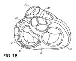
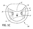
図1A~図1Dを参照すると、左心房10、右心房20、左心室30、および右心室40という、心臓の4つの心腔が示されている。僧帽弁60は左心房10と左心室30との間に配設されている。また、右心房20と右心室40を分離する三尖弁50、大動脈弁80、および肺動脈弁70も示されている。僧帽弁60は、前尖12および後尖14という2つの弁尖で構成される。健康な心臓では、2つの弁尖は、収縮期中は接合区域16で並置される。
1A-1D, the four chambers of the heart are shown: left
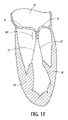
心臓骨格の線維性弁輪120の部分は、前尖12および後尖14と呼ばれる僧帽弁の2つの弁尖に付着する。弁尖は、腱索32に付着することによって軸線方向で支持される。索は、次いで、左心室の乳頭筋34、36の一方または両方に付着する。健康な心臓では、索支持構造が僧帽弁尖を係留して、弁尖が拡張期中は簡単に開くが、心室収縮期中に生じる高圧には抵抗することを可能にしている。支持構造の係留作用に加えて、弁尖の形状および組織が一貫していることが、有効な封止または接合を促進する助けとなる。前尖および後尖の前縁部は、漏斗状の接合区域16に沿って合わさり、三次元の接合区域(CZ)の横断面160が図1Eに概略的に示されている。
The
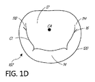
僧帽弁前尖および後尖は異なるように形作られている。前尖は、中心線維体(心臓骨格)の上に重なる弁輪によりしっかりと付着されており、より動きやすい後僧帽弁輪に付着された後尖よりもある程度硬い。閉止範囲の約80パーセントが前尖である。交連110、114に隣接して、弁輪120上またはその前方には、僧帽弁輪が大動脈の無冠尖の基部と融合するところに形成される、左(外側)線維三角124および右(中隔)線維三角126がある(図1F)。線維三角124、126は、中心線維体128の中隔および外側の範囲を形成する。線維三角124、126は、いくつかの実施形態では、1つ以上の弁輪または心房アンカーと安定して係合するしっかりした区域を提供するという利点を有してもよい。弁尖12、14の間の接合区域CLは単純な線ではなく、それよりもむしろ、湾曲した漏斗状の境界面である。第1の交連110(外側または左側)および第2の交連114(中隔または右側)は、弁輪120で前尖12が後尖14と合わさるところである。図1C、図1D、および図1Fの心房から見た軸線方向図で最もはっきり分かるように、接合区域の軸線方向断面は、弁輪中心CAから、ならびに拡張期中の弁を通る開口部COから分離した、曲線CLを全体的に示している。それに加えて、弁尖縁は波形であり、前尖に比べて後尖の方がより大きい波形である。接合不全は、これらのA-P(前後)セグメント対A1/P1、A2/P2、およびA3/P3の1つ以上の間で生じる可能性があるので、接合不全の特性は接合区域の曲線CLに沿って変動することがある。
The mitral valve anterior and posterior leaflets are shaped differently. The anterior leaflet is more firmly attached by the annulus overlying the central fibrous body (cardiac skeleton) and is somewhat stiffer than the posterior leaflet, which is attached to the more mobile posterior mitral annulus. About 80 percent of the closed area is the anterior leaflet. Adjacent to the
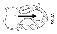
次に図2Aを参照すると、心臓の適切に機能している僧帽弁60は、拡張期中は開いて、血液が流路FPに沿って左心房から左心室30に向かって流れ、それによって左心室に充満することを可能にしている。図2Bに示されるように、機能している僧帽弁60は、収縮期中は、心室圧力の増加によって最初は受動的に、次に能動的に閉じて、左心室30を左心房10から有効に封止し、それによって左心室を取り囲む心臓組織の収縮を可能にして、血管系全体を通して血液を前進させる。
Referring now to FIG. 2A, a properly functioning
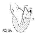
図3A~図3Bおよび図4A~図4Bを参照すると、僧帽弁の弁尖縁が十分に対置できず、それによって収縮期中に血液が心室から心房へと逆流している、いくつかの状態または病的状態がある。特定の患者の具体的な病因にかかわらず、心室収縮期中に弁尖が封止できないことは、接合不全として知られており、僧帽弁逆流を引き起こす。 3A-3B and 4A-4B, several conditions in which the leaflet margins of the mitral valve do not adequately appose, thereby allowing blood to flow back from the ventricle to the atrium during systole. or have a medical condition. Regardless of the specific etiology in a particular patient, the failure of the leaflets to seal during ventricular systole is known as mal-coaptation and causes mitral regurgitation.
一般に、接合不全は、一方もしくは両方の弁尖の支持構造による過度の係留によって、または支持構造の過度の伸長もしくは断裂によって生じる場合がある。他の一般的でない原因としては、心臓弁の感染、先天性異常、および外傷が挙げられる。弁の機能不全は、僧帽弁逸脱として知られる腱索の伸長によって、また場合によっては、図3Aに示されるような、動揺弁尖220として知られる索215または乳頭筋の断裂によって生じる場合がある。あるいは、弁尖組織自体が余剰の場合、弁が逸脱することがあるので、接合が心房内に入り込む度合いが高いほど、心室収縮期230中の心房内における弁の開放が大きくなる。弁尖のどちらか一方が逸脱または動揺する場合がある。この状態は、場合によっては、変性性僧帽弁逆流として知られている。
In general, malcoaptation may result from excessive anchoring of one or both leaflets by the supporting structure, or from excessive stretching or tearing of the supporting structure. Other less common causes include heart valve infections, congenital anomalies, and trauma. Valve insufficiency can be caused by elongation of the chordae tendineae, known as mitral valve prolapse, and in some cases, tearing of the
図3Bに示されるような過度の係留の場合、正常な構造の弁の弁尖は、弁輪の拡大または形状変化、いわゆる弁輪拡張240により、適切に機能しないことがある。かかる機能性僧帽弁逆流は、一般に、心筋の障害およびそれに付随する心室拡張によってもたらされる。また、機能性僧房弁逆流によって生じる過度の量の荷重自体が、心不全、心室拡張および弁輪拡張を悪化させ、結果として僧帽弁逆流を悪化させる場合がある。
In the case of excessive anchoring, such as that shown in FIG. 3B, the leaflets of a normally constructed valve may not function properly due to the enlargement or shape change of the annulus, so-called
図4A~図4Bは、機能性僧帽弁逆流(図4A)および変性性僧帽弁逆流(図4B)における収縮期中の血液の逆流BFを示している。図4Aにおける弁輪のサイズ増大は、心室320および乳頭筋330の肥大による係留の増大と併せて、前尖312および後尖314の並置を妨げ、それによって接合を妨げている。図4Bでは、索215の断裂によって、左心房内へと上向きに後尖344が逸脱して、前尖342に対する並置を妨げている。いずれの状況でも、結果は心房内への血液の逆流であり、それによって左心室圧迫の有効性が減少する。
Figures 4A-4B show regurgitation BF of blood during systole in functional mitral regurgitation (Figure 4A) and degenerative mitral regurgitation (Figure 4B). The increased size of the annulus in FIG. 4A, along with increased anchoring due to hypertrophy of the
本明細書の開示と併せて利用することができる、接合補助要素、ツール、アンカー、特徴、システム、および方法の更なる説明を、以下の出願に見出すことができ、それらの出願の全体を参照により本明細書に援用する。2011年5月3日出願の米国特許出願第13/099,532号、2012年6月22日出願の米国特許出願第13/531,407号、2014年6月24日出願の米国特許出願第14/313,975号、2015年6月17日出願の米国特許出願第14/742,199号、2015年6月24日出願の米国特許出願第14/749,344号、および2003年4月18日出願の米国特許出願第10/419,706号。 Additional descriptions of coaptation aids, tools, anchors, features, systems, and methods that can be utilized in conjunction with the disclosure herein can be found in the following applications, which are incorporated by reference in their entireties: is hereby incorporated by reference. U.S. Patent Application No. 13/099,532 filed May 3, 2011; U.S. Patent Application No. 13/531,407 filed June 22, 2012; U.S. Patent Application No. 14/313,975 filed June 24, 2014 , U.S. patent application Ser. No. 14/742,199 filed June 17, 2015, U.S. patent application Ser. 419,706.
いくつかの実施形態では、本明細書に記載する接合補助要素は、後尖、索、および乳頭筋の上に重なるように配備されてもよい。いくつかの実施形態では、接合補助要素は、弁輪の後面には上から、左心室の後面には下から、弁輪アンカーおよび/または心室アンカーを介して付着する。他の実施形態では、1つを超える弁輪アンカーおよび/または1つを超える心室アンカーが、接合補助要素を取り付けるのに使用されてもよい。いくつかの要素では、1つ以上の弁輪アンカーが、いくつかの実施形態では環状であることができる、1つ以上の心房または交連アンカーと置換されるかまたはそれによって補足されてもよい。接合補助要素は、後弁輪の上面、心房後壁、または弁輪自体に付着してもよい。接合区域は、接合補助要素と天然の前尖との間に確立されている。弁尖接合不全は、機能異常の背景にある機序にかかわらず、機能性および変性性両方の僧帽弁逆流において起こるので、類似の接合補助要素を両方で使用することができる。いくつかの実施形態では、天然の前尖が適切に確立された接合点で接合要素と並置して、心室収縮中の血流を阻害するようにして、異なるサイズの接合補助要素を配置することができる。 In some embodiments, coaptation assist elements described herein may be deployed to overlie the posterior leaflets, chordae, and papillary muscles. In some embodiments, the coaptation assist element is attached to the posterior aspect of the annulus from above and to the posterior aspect of the left ventricle from below via annulus anchors and/or ventricular anchors. In other embodiments, more than one annulus anchor and/or more than one ventricular anchor may be used to attach the coaptation assist element. In some elements, one or more annulus anchors may be replaced or supplemented by one or more atrial or commissural anchors, which in some embodiments may be annular. The coaptation assist element may adhere to the superior surface of the posterior annulus, the posterior atrial wall, or the annulus itself. A coaptation zone is established between the coaptation auxiliary element and the native anterior leaflet. Since leaflet mal-coaptation occurs in both functional and degenerative mitral regurgitation, regardless of the mechanism underlying the dysfunction, similar coaptation assist elements can be used in both. In some embodiments, different sized coaptation assisting elements are placed such that the natural anterior leaflet is apposed to the coaptation element at a well-established coaptation point to inhibit blood flow during ventricular contraction. can be done.
様々なサイズの接合補助要素が提供されてもよく、異なる寸法は様々な解剖学的構造に適合するように構成される。例えば、弁輪によって規定される面に対して基本的に垂直な面内で、上方の弁輪取付け部位から接合補助要素の最下方縁部までを測定する高さと、接合点と上方取付け部位との間の深さと、接合点の高さにおける後壁と接合点との間の突出とがあってもよい。また、一般的には機能性MRの場合の方が大きい、接合補助要素の内側外側直径もある。拡張期の間、接合補助要素は実質的に同じ位置に留まってもよく、一方で天然の前尖の移動によって弁が開いて、左心房から左心室への血流が最小限の制限で可能になる。いくつかの実施形態では、心室収縮期中、接合補助要素の表面は上向きに膨らむかまたは伸長してもよく、アンカーは動かないままである。これは、収縮期中の接合区域において、要素の前面または接合表面と天然の弁尖との間の封止を向上させるので、有利なことがある。拡張期の間、表面は、前尖に向かってより前側にある、最初の位置に戻ってもよい。これによって、拡張期中の心房と心室との間の血流経路が改善されて、接合補助要素を越える心房からの流出を改善してもよい。 Various sizes of coaptation aid elements may be provided, with different dimensions configured to fit various anatomies. For example, the height measured in a plane essentially perpendicular to the plane defined by the annulus from the superior annulus attachment site to the lowest edge of the coaptation assist element, the junction point and the superior attachment site. There may be a depth between and a protrusion between the rear wall and the junction at the height of the junction. There is also the inner-outer diameter of the coaptation aid, which is generally larger for functional MR. During diastole, the coaptation assisting element may remain substantially in the same position, while natural anterior leaflet movement opens the valve to allow blood flow from the left atrium to the left ventricle with minimal restriction. become. In some embodiments, during ventricular systole, the surface of the coaptation assist element may bulge or stretch upward while the anchor remains stationary. This can be advantageous as it improves the seal between the anterior or coaptation surface of the element and the native leaflets at the coaptation area during systole. During diastole, the surface may return to its initial position, more anterior towards the anterior leaflet. This may improve the blood flow path between the atrium and ventricle during diastole to improve outflow from the atrium over the coaptation accessory.
いくつかの使用方法では、天然の後尖は適所に残され、接合補助要素は後弁輪または隣接した心房壁に上方から取り付けられる。多くの可能な代替実施形態は、異なる取付けメカニズムを有してもよい。他の使用方法では、後尖は存在せず、外科的にまたは疾患の結果として除去されている。いくつかの使用方法では、天然の弁尖は接合補助要素の後面に付着する。いくつかの使用方法では、接合補助要素は、弁輪または心房壁ではなく、後尖の前面に付着してもよい。これらは、いくつかの変形例であるが、更に他のものが想起される。いくつかの使用方法では、固定構造(図示せず)が、接合補助要素から心房壁を通って冠状静脈洞内へと通ることができ、固定構造は冠状静脈洞内の噛合構造に付着する。いくつかの使用方法では、固定構造は、機械的構造または単純な縫合糸であることができ、心房壁を貫通し、心臓の心外膜表面で結び目またはクリップなどの機械的要素によって固定することができる。同様に、下方からの取付けは、心室筋に対してであってもよく、心尖を通って心外膜または心膜に入り、外側から固定されてもよく、または代替の取付け手段を使用して他の取付け部位で固定されてもよい。 In some uses, the natural posterior leaflet is left in place and the coaptation assist element is attached to the posterior annulus or adjacent atrial wall from above. Many possible alternative embodiments may have different attachment mechanisms. In other uses, the posterior leaflet is absent and has been removed surgically or as a result of disease. In some uses, the native leaflets attach to the posterior surface of the coaptation assist element. In some uses, the coaptation assist element may attach to the anterior surface of the posterior leaflet rather than the annulus or atrial wall. These are some variations, but still others come to mind. In some methods of use, a fixation structure (not shown) can pass from the coaptation assist element through the atrial wall and into the coronary sinus, where the fixation structure attaches to an engaging structure within the coronary sinus. In some uses, the fixation structure can be a mechanical structure or a simple suture that penetrates the atrial wall and is secured by a mechanical element such as a knot or clip at the epicardial surface of the heart. can be done. Similarly, attachment from below may be to the ventricular muscle, through the apex into the epicardium or pericardium and secured from the outside, or using alternative attachment means. It may be fixed at other attachment sites.
本明細書に記載する接合補助要素は、多数の所望の特性を示してもよい。いくつかの実施形態は、(弁輪組織の熱収縮、人工弁輪リングの埋込み、および/または弁面の上方もしくは下方、または冠状静脈洞もしくは関連する血管内における締付けメカニズムの配置などによる)僧帽弁輪の作り直しに依存する必要はない。有利には、弁尖構造を破壊する必要がなく、僧帽弁尖を共に係止または融合することに依存する必要もない。多くの実施形態は、心室の作り直しに対する依存を回避することができ、埋込み後は、可動域が限定されて非常に長い疲労寿命をもたらしてもよい、受動的な埋込みデバイスを表す。したがって、接合補助要素を後尖全体に固定し、その他は天然の心臓(例えば、心室、僧帽弁輪など)の解剖学的構造を無傷のまま残すことができる。 The coaptation aid elements described herein may exhibit a number of desirable properties. Some embodiments include the use of a constriction mechanism (such as by heat shrinking the annulus tissue, implanting a prosthetic annulus ring, and/or placing a clamping mechanism above or below the valve plane, or within the coronary sinus or associated vessel). There is no need to rely on remodeling of the annulus. Advantageously, there is no need to disrupt the leaflet structure and rely on locking or fusing the mitral valve leaflets together. Many embodiments represent passive implant devices that can avoid reliance on remodeling of the ventricle and, once implanted, may have a limited range of motion resulting in very long fatigue life. Thus, the coaptation assist element can be anchored across the posterior leaflet while otherwise leaving the native heart anatomy (eg, ventricle, mitral annulus, etc.) intact.
僧帽弁接合不全の軽減は、どの弁尖セグメントが接合不全を起こしているかにかかわらず有効であってもよい。本明細書に記載する治療は、処置中に再位置付け可能であって、更には完全に配備した後および/または組織の応答が始まるかもしくは完了した後であっても除去可能であり、弁構造を損傷しない場合が多い、接合補助要素を利用することになる。それでもなお、本明細書に記載する接合補助要素は、不要になるものと上述した属性のうち1つ以上に依存する、1つ以上の療法と組み合わされてもよい。接合補助要素は、良性組織の治癒および迅速な内皮化を呈することができ、それによって転位、血栓塞栓症、感染、および/またはびらんを阻害する。場合によっては、接合補助要素は内皮化を呈さず、その表面が不活性なままであり、それによっても転位、血栓塞栓症、感染、および/またはびらんを阻害することができる。 Mitigation of mitral valve mal-coaptation may be effective regardless of which leaflet segment is mal-coapted. The treatments described herein can be repositioned during the procedure and even removed after full deployment and/or after the tissue response has begun or completed and the valvular structure is removed. Joining aids are used, which often do not damage the Nonetheless, the coaptation adjuvant elements described herein may be combined with one or more therapies dependent on one or more of the attributes described above as dispensable. Coaptation assisting elements can exhibit healing and rapid endothelialization of benign tissue, thereby inhibiting dislocation, thromboembolism, infection, and/or erosion. In some cases, the coaptational auxiliary element does not exhibit endothelialization and remains inert on its surface, which can also inhibit dislocation, thromboembolism, infection, and/or erosion.
図5A~図5Bは、接合補助要素500の一実施形態の2つの図を示している。接合補助要素500は、接合不全を起こしている天然の弁尖、僧帽弁の場合は後尖に向かって配設される第1の表面505と、前尖に向かって配設されてもよい第2の表面515とを含むことができる。第2の表面515は接合表面560を含むことができる。接合補助要素500の上縁部540は、本明細書に記載するように、弁輪または隣接する心房壁の全体形状に合致するように湾曲されてもよい。上縁部540は、図5Aに示されるように、後尖に向かって下向きに湾曲させるか、または図6に示され本明細書に記載されるように、左心房壁の全体形状に合致するように心房壁に向かって上向きに湾曲させることができる。
5A-5B show two views of one embodiment of a
接合補助要素500は、心房および心室内の取付け部位の間で弁を横断できるような幾何学形状を有することができる。いくつかの実施形態では、取付け部位は心房内のみにある。いくつかの実施形態では、取付け部位は弁の弁輪および交連付近のみにある。接合補助要素500は、下縁部580付近では取り付けないことができる。接合補助要素500は心室取付けを要しない。いくつかの実施形態では、接合補助要素500の幾何学形状は、弁内における接合補助要素500の位置を維持する助けとなる。いくつかの実施形態では、接合補助要素500は後尖を覆うように湾曲される。いくつかの実施形態では、接合補助要素500は上縁部540に向かって後向きに湾曲される。接合補助要素500は、前尖がそこに接して接合する接合表面560を提供してもよい。図5Aおよび図5Bはその幾何学形状を示している。
Coaptation assist
いくつかの使用方法では、後尖は無傷のままにすることができる。接合補助要素500は、後尖を効率的に封止するように心房または弁輪に付着してもよい。いくつかの使用方法では、後尖は除去することができる。接合補助要素500は、弁尖が除去されるかまたは既に除去されている場合、後尖に取って代わることができる。いくつかの実施形態では、接合補助要素500は弁輪の取付けのみを要する。いくつかの実施形態では、接合補助要素500は単一点での取付けのみを要する。単一点は、接合補助要素500の中央位置、例えば中央に位置するハブであってもよい。いくつかの実施形態では、接合補助要素500は、縁部に沿って心房または弁輪に付着してもよい。いくつかの実施形態では、接合補助要素500は、接合補助要素500の縁部から離れた位置で、例えば中央に位置するハブで、心房または弁輪に付着してもよい。
In some methods of use, the posterior leaflet can be left intact. Coaptation assist
接合補助要素500は、弁輪アンカー800を係合する弁輪ハブ520を含むことができる。弁輪アンカー800は、本明細書に記載する、ドライバによって近位端で係合されてもよい。弁輪アンカー800は、組織を係合する尖った先端を含むことができる。いくつかの使用方法では、接合補助要素500を送達する間、弁輪アンカー800の先端は弁輪ハブ520内にある。いくつかの使用方法では、送達中、弁輪アンカー800の先端は環状区画510の上方にある。弁輪アンカー800の先端は、弁輪アンカー800を回転させて組織を係合するまで、弁輪ハブ520内に入り込んだままであることができる。いくつかの実施形態では、接合補助要素500は、体外で組み立てて、弁輪ハブ520を介して弁輪アンカー800を接合補助要素500に、またドライバを弁輪アンカー800に係合することができる。ドライバは、次に、接合補助要素500が折畳み位置にある状態で、送達カテーテル内へと撤回することができる。ドライバは、施術者によって、弁輪アンカー800を適切な位置に配置するように別個に操作されてもよい。あるいは、弁輪アンカー800は、送達カテーテルを通して配備する前または後に、接合補助要素500および/またはドライバに逐次的に係合されてもよい。接合補助要素500は、配置後は後尖を完全に覆って、収縮期中は接合補助要素500が前尖と接合し、天然の前尖を用いて環状リングでの弁封止を維持することができる。
The
いくつかの実施形態では、弁輪アンカー800は能動アンカーである。ユーザは、選択的に弁輪アンカー800を係合し、または組織から係脱することができる。返しまたは他の受動アンカーとは異なり、能動アンカーは、組織を係合するためには回転などによって活性化させることができる。弁輪アンカー800によって、弁輪アンカー800を係合する前に接合補助要素500を配置することが可能になる。接合補助要素500は、弁輪アンカー800に何ら接着することなく、組織と接触することができる。いくつかの実施形態では、弁輪アンカー800および対応するハブ520は、接合補助要素500上の中央に配置される。弁輪アンカー800および対応するハブ520は、接合補助要素500のいずれの縁部からも離隔される。弁輪アンカー800および対応するハブ520の位置は、接合補助要素500が弁輪ハブ520によって保持されたときの接合補助要素500の揺れを防ぐ、中立の中央であることができる。対応するハブ520は、接合補助要素500を保持し移動させる便利な位置を提供する。
In some embodiments,
弁輪ハブ520は、内蔵のまたは結合された弁輪アンカー800を有してもよい。いくつかの実施形態では、弁輪アンカー800は、弁輪ハブ520内で、本明細書に記載するクロスピンによって保定することができる。クロスピンは、弁輪アンカー800のらせん構造を貫通して、鈍力によって弁輪アンカー800が弁輪ハブ520から外れるのを防いでもよい。弁輪アンカー800は、弁輪ハブ520に対して回転可能ならせんを含んでもよい。いくつかの実施形態では、他のアンカーが使用されてもよい。弁輪アンカー800は、接合補助要素500から心室中隔を通って右心室まで延在する、係留具または他の取付け手段の形態であってもよい。弁輪アンカー800は、心尖を通って心外膜または心膜内へと延在する、係留具または他の取付け手段の形態であってもよい。弁輪アンカー800は、心臓の外側から、組み合わされた心内膜側/心外膜側処置で固定されてもよい。らせん状のアンカーが使用される場合、プラチナ/Ir、ニチノール合金、および/またはステンレス鋼など、生体不活性材料を含んでもよい。
The
いくつかの実施形態では、接合補助要素500は、弁輪ハブ520内部に単一の中央弁輪アンカー800を含むことができる。接合補助要素500は、送達カテーテルを弁輪ハブ520に取り付けることによって、本明細書に記載するように経皮的に送達することができる。接合補助要素500は、弁輪アンカー800を除去および再取付けすることによって、調節可能な位置付け向けに構成することができる。接合補助要素500は、弁輪アンカー800を除去し、接合補助要素500を撤回することによって、再捕捉可能であることができる。接合補助要素500はまた、交連アンカー、心室アンカー、弁輪アンカー、返し、係留具、または他の任意の既知の固着デバイスを含む、補助アンカーを含むことができる。
In some embodiments, the coaptation assist
図5A~図5Bに見ることができるように、接合補助要素500は複数の支柱530を含むことができる。いくつかの実施形態では、支柱530の1つ以上は、ハブ520で終端する一端と、接合補助要素500の上縁部540、横縁部570および575、ならびに下縁部580のうちの1つに向かって径方向外向きに延在する他端とを有する。支柱530は、ハブ520から様々な方向で外向きに延在してもよく、規則的または不規則な間隔で、隣接する支柱530から離隔することができる。いくつかの実施形態では、隣接する支柱530は、隣接する支柱530に対して約5度~約45度、約10度~約30度、または約5、10、15、20、25、もしくは30度の角度で、ハブから外向きに延在する。支柱530は、配置の際に接合補助要素500の形状を維持するのを補助するため、接合補助要素500の長手方向軸線に対してほぼ平行に配列されてもよい。支柱530は、接合補助要素500がカテーテルを通して配備するために低減された構成をとることを可能にしてもよい。いくつかの実施形態では、インプラント500の接合区域の一部分を形成する支柱530は、インプラントの環状区域の一部分のみを形成する支柱530よりも長い最大長さを有する。いくつかの実施形態では、インプラントの接合区域の一部分を形成する支柱530は、例えば、インプラントの環状区域の一部分を形成する支柱530よりも、少なくとも約10%、20%、30%、40%、50%、75%、100%、125%、または150%長いものであることができる。
As can be seen in FIGS. 5A-5B, the
図5Aは、弁輪アンカー部位535を有する接合補助要素500の図を示している。弁輪アンカー部位535は支柱530の一部分であることができる。弁輪アンカー部位535は、図5Aの接合補助要素500から下向きに延在して示されている。他の実施形態では、弁輪アンカー部位535は、接合補助要素500から他の方向で延在して、組織を係合してもよい。いくつかの実施形態では、弁輪アンカー部位535は、尖った先端を有する1つ以上の返しを備える。弁輪アンカー部位535は受動アンカーであってもよい。
FIG. 5A shows a view of a
いくつかの実施形態では、接合補助要素500は1つ以上の後退可能な返しを含むことができる。例えば、返しは、接合補助要素500の送達中に後退させることができる。例えば、返しは、接合補助要素500が解剖学的構造に対して位置付けられた後に前進させることができる。いくつかの実施形態では、返しは能動的に後退および/または前進させられる。例えば、本明細書に記載する送達カテーテルは、返しを後退および/または前進させるように設計された、返しに結合されたメカニズムを含むことができる。他の実施形態では、返しは受動的に前進および/または後退させられる。いくつかの実施形態では、接合補助要素500は返しが後退状態にある形で送達される。いくつかの実施形態では、返しは、本明細書に記載するような弁体カバーによって覆うことができる。いくつかの実施形態では、組織と弁体カバーとの間の境界面は、弁体カバーを押し戻し、返しを露出させる。いくつかの実施形態では、組織は、弁体カバーの一部分を溶解および/または吸収し、返しを露出させる。いくつかの実施形態では、本明細書に記載する巾着縫合糸の動きによって返しが前進する。いくつかの実施形態では、巾着縫合糸の動きによって弁体カバーが動いて返しを露出させる。他の構成が想起される。
In some embodiments, the
弁輪アンカー部位535は、いくつかの実施形態では、天然の弁の内側交連と外側交連との間の距離、即ち交連間距離(intracommissural distance、ICD)に対応してもよい、図5Bに示される直径D1を規定してもよい。D1は、20~60mmの範囲であってもよく、いくつかの実施形態では、好ましい長さは、最も広い範囲のヒト僧帽弁のICDに最も近い、35~45mmである。いくつかの実施形態では、D1は、右線維三角から左線維三角までの距離であってもよい。
The
接合補助要素500は、ほぼ環状の区画510を含むことができる。環状区画510は、接合補助要素500が配備されるとき、天然の弁尖の上方に位置付けることができる。いくつかの実施形態では、環状区画510は、弁輪に向かって湾曲されるか、または弁輪から離れる方向で湾曲されてもよい。環状区画510は凹状であることができる。他の実施形態では、環状区画510は弁輪に対して実質的に平坦であってもよい。支柱530の1つ以上は、ハブ520から上縁部540に向かって横方向に湾曲して、配備の際に、接合補助要素500の環状区画510の形状を維持するのを支援してもよい。接合補助要素500は、ハブ520から弁輪アンカー部位535に向かって下向きに湾曲することができる。いくつかの実施形態では、接合補助要素500は後尖に接しない。いくつかの実施形態では、弁輪アンカー部位535は、僧帽弁の後弁輪と接合補助要素500の唯一の接点である。上縁部540は環状の曲率半径を含むことができる。環状曲線半径は弁輪に向かって湾曲することができる。環状曲線半径は接合表面560に向かって湾曲することができる。いくつかの実施形態では、環状曲線半径は、0mm~5mm、5mm~10mm、10mm~15mm、15mm~20mm、20mm~25mm、25mm~30mmなどであることができる。
支柱530は、X線不透過性材料で構成されてもよい。いくつかの実施形態では、支柱530は、形状記憶金属、例えばニチノール、または形状記憶ポリマーなど、弾性的に変形可能な材料で構成される。いくつかの実施形態では、材料はエルジロイである。他の実施形態では、支柱530は、ステンレス鋼、ポリプロピレン、高密度ポリエチレン(PE)、ダクロン、SISなどの無細胞コラーゲンマトリックス(acellular collagen matrix)、または他のプラスチックなどを含むように、他の材料で構成されてもよい。他の実施形態では、支柱530は、高密度PEシースと、それに囲まれたePTFE、ダクロン、および/またはポリプロピレンのコアなどの組み合わせであってもよい。支柱530は、円形断面もしくは楕円形断面を有してもよく、またはリボン形であってもよい。いくつかの実施形態では、支柱530はコイルばねまたはジグザグ形状である。支柱530は一貫した剛性を有してもよい。いくつかの実施形態では、1つ以上の支柱530は、1つ以上の支柱530の長さに沿って異なる剛性を有することができる。支柱530は、接合補助要素500の心室側端部よりも弁輪側端部の方が剛性が高くてもよい。支柱530は、接合補助要素500の心室側端部よりも弁輪側端部の方が剛性が低くてもよい。支柱530は、中点で、例えば反曲点または曲線において剛性が高くてもよい。支柱530は、1つ以上の他の支持構造と共に、フレームを形成することができる。いくつかの実施形態では、接合補助要素500の上縁部540に平行に延び、上縁部540の形状を維持するのを支援する、1つ以上の支持構造が提供されてもよい。支柱530および/またはフレームの他の支持構造は、いくつかの実施形態では、ニチノールチューブからレーザー切断することができる。
The
接合補助要素本体カバー550は、ePTFEなどの材料で構成されてもよい。接合補助要素本体カバー550の他の材料としては、ポリエステル、ポリウレタン発泡体、ポリカーボネート発泡体、ブタ心膜などの生体組織、処理済みのウシ心膜、胸膜、腹膜、シリコーン、ダクロン、無細胞コラーゲンマトリックスなどが挙げられる。いくつかの実施形態では、接合補助要素本体カバー550は、ePTFEに取り囲まれた発泡体材料を含むことができる。スポンジまたは発泡体材料の使用によって、接合補助要素500を折り畳んでカテーテルに通すのに十分に小さい直径にする能力が向上する。いくつかの実施形態では、接合補助要素本体カバー550は孔を有さない。他の実施形態では、接合補助要素本体カバー550は、内皮化および細胞取付けを向上させる細孔を有してもよい。接合補助要素本体カバー550はまた、より良好な可視化のため、X線不透過性材料またはエコー増強材料を組み込んでもよい。支柱530またはハブ520の支持境界面を含む、接合補助要素500の任意の支持構造は、金またはプラチナまたはバリウム含浸材などのX線不透過性材料で覆われてもよい。接合表面560はエコー増強材料で覆われてもよい。接合補助要素本体カバー550は、ヘパリン結合もしくはキノリンおよびキノキサリン化合物などの血栓症を阻害する材料で、または内皮化を加速する材料で、または感染を阻害する抗生物質で覆われてもよい。いくつかの実施形態では、本明細書に記載する巾着縫合糸1010は、より良好な可視化のため、X線不透過性材料またはエコー増強材料を組み込むことができる。
Coaptation aid
いくつかの実施形態では、支柱530は、接合補助要素本体カバー550の層の間に挟み込まれてもよい。接合補助要素本体カバー550は、第1の表面505および第2の表面515上において同じ材料で構成されてもよい。接合補助要素本体カバー550は、第1の表面505またはその一部分および第2の表面515またはその一部分上において異なる材料で構成されてもよい。いくつかの実施形態では、支柱530は、接合補助要素本体カバー550の単一層の第1の表面505もしくは第2の表面515に取り付けられるか、またはそれに埋め込まれてもよい。いくつかの実施形態では、支柱530は、接合補助要素本体カバー550を通して「縫い込まれて」もよい。弁輪アンカー部位535は、接合補助要素本体カバー550から露出した支柱530の端部であることができる。
In some embodiments, struts 530 may be sandwiched between layers of coaptation aid
接合補助要素500は巾着縫合糸1010を含むことができる。巾着縫合糸1010は接合補助要素500の一部分に沿って延在することができる。巾着縫合糸1010は上縁部540またはその一部分に沿って延在することができる。巾着縫合糸1010は横縁部570またはその一部分に沿って延在することができる。巾着縫合糸1010は横縁部575またはその一部分に沿って延在することができる。巾着縫合糸1010は下縁部580またはその一部分に沿って延在することができる。巾着縫合糸1010は接合補助要素500の周囲またはその一部分に沿って延在することができる。巾着縫合糸1010は1つ以上の支柱530に沿って延在することができる。巾着縫合糸1010は、直線経路、非直線経路、曲線、半円、または任意の開形状もしくは閉形状で延在することができる。
いくつかの実施形態では、巾着縫合糸1010は弁体カバー550の層の間に挟み込まれてもよい。例えば、巾着縫合糸1010は、接合補助要素本体カバー550の層間の管腔内に配設することができる。いくつかの実施形態では、巾着縫合糸1010は、弁体カバー550の単一層の第1の表面505もしくは第2の表面515に取り付けられるか、またはそれに埋め込まれてもよい。いくつかの実施形態では、巾着縫合糸1010は、接合補助要素本体カバー550を通して「縫い込まれて」もよい。巾着縫合糸1010は、第1の表面505から第2の表面515へと通り、第1の表面505に戻ることができる。巾着縫合糸1010は、接合補助要素本体カバー550から露出した1つ以上の端部を含むことができる。巾着縫合糸1010がループである実施形態では、巾着縫合糸は、弁体カバーからのループの1つ以上の露出区画を含むことができる。
In some embodiments, the
接合補助要素500は、巾着縫合糸1010を引き締めることによって折り畳まれてもよい。接合補助要素500は、巾着縫合糸1010を緩めることによって拡張されてもよい。1つ以上の露出端部またはループは、送達カテーテルまたは他のツールで巾着縫合糸1010を引き締めるかもしくは緩めることによって、操作することができる。接合補助要素500を折り畳むかまたは拡張できることは、接合補助要素500の再捕捉および/または接合補助要素500の再位置付けに有益なことがある。
接合補助要素500は、1つ以上の巾着縫合糸1010を引き締めることおよび/または1つ以上の巾着縫合糸1010を緩めることによって回転させてもよい。例えば、横縁部570で1つ以上の巾着縫合糸1010を引き締めること、および/または横縁部575で1つ以上の巾着縫合糸1010を緩めることで、接合補助要素500を回転させてもよい。1つ以上の巾着縫合糸1010は、多方向の回転を可能にするように接合補助要素500に結合されてもよい。
接合補助要素500は、巾着縫合糸1010を緩めることによって拡張されてもよい。1つ以上の露出端部またはループは、送達カテーテルまたは他のツールで巾着縫合糸1010を引き締めるかもしくは緩めることによって、操作することができる。接合補助要素500を折り畳むかまたは拡張できることは、接合補助要素500の再捕捉および/または接合補助要素500の再位置付けに有益なことがある。
接合補助要素500の接合表面560は、巾着縫合糸1010の動きによって調節されてもよい。1つ以上の露出端部またはループは、送達カテーテルまたは他のツールで巾着縫合糸1010を引き締めるかもしくは緩めて、接合表面560の曲率を現場で変更することによって操作することができる。接合補助要素500の曲率を調節できることは、前尖の幾何学形状を含む心臓の幾何学形状に合わせて適合するのに有益なことがある。
接合補助要素500の環状寸法は、巾着縫合糸1010の動きによって調節されてもよい。1つ以上の露出端部またはループは、送達カテーテルもしくは他のツールで巾着縫合糸1010を引き締めるかまたは緩めて、接合補助要素500の1つ以上の寸法を現場で変更することによって操作することができる。接合補助要素500の寸法を調節できることは、心臓の幾何学形状に合わせて適合するのに有益なことがある。
The annular dimension of
接合補助要素500は1つ以上の巾着縫合糸1010を含むことができる。いくつかの実施形態では、接合補助要素500は、1本の巾着縫合糸、2本の巾着縫合糸、3本の巾着縫合糸、4本の巾着縫合糸、5本の巾着縫合糸、6本の巾着縫合糸、7本の巾着縫合糸、8本の巾着縫合糸、9本の巾着縫合糸、10本の巾着縫合糸などを含む。例えば、巾着縫合糸1010は、接合補助要素500の各縁部に沿って延在することができる。複数の巾着縫合糸が設けられる場合、巾着縫合糸1010は共に作用して、接合補助要素500の構成を変更することができる。複数の巾着縫合糸が設けられる場合、巾着縫合糸1010は独立して作用して、接合補助要素500の構成を変更することができる。
図5Aは、弁輪によって規定される面に対して垂直に測定した下縁部580と弁輪ハブ520との間の距離に対応する、接合要素高さを更に示している。いくつかの実施形態の接合要素高さは、10~80mmであってもよく、いくつかの実施形態では40~55mmの範囲である。接合要素高さは、10~20mm、20~30mm、30~40mm、40~50mm、50~60mm、60~70mm、70~80mmなどであることができる。
FIG. 5A also shows the coaptation element height, which corresponds to the distance between the
図5Aは、接合補助要素500が、上縁部540と、横縁部570および575と、下縁部580とを有するような、接合補助要素500のほぼ三角形の形状を示している。いくつかの実施形態では、上縁部540は下縁部580よりも長い長さを有するので、横縁部570および575の間の横断方向距離は、接合補助要素500の上部から下部までで全体的に減少する。例えば、上縁部540の長さは、15~50mmまたは25~35mmの範囲であってもよく、下縁部580の長さは、1~15mmまたは2~6mmの範囲であってもよい。
FIG. 5A shows the generally triangular shape of the
弁輪ハブ520は、ハブ、アイレット、または当該分野で知られている他の任意の係留部位であってもよい。いくつかの実施形態では、弁輪ハブ520は距離D1の中点に位置する。いくつかの実施形態では、弁輪ハブ520は、接合補助要素500が弁輪ハブ520によって保持されたときの接合補助要素500の揺れを防ぐ、中立の中央に位置する。他の実施形態では、弁輪ハブ520は交連の1つに位置する。1つの弁輪アンカー800のみが示されているが、他の実施形態では、2つ以上の弁輪ハブ520が設けられてもよい。
いくつかの実施形態では、支柱530はNiTi管材を含むことができる。いくつかの実施形態では、支柱530は管材からレーザー切断することができる。いくつかの実施形態では、1つ以上の支柱530および/または1つ以上の支持構造を含むフレームを、単一の材料片からレーザー切断することができる。いくつかの実施形態では、1つ以上の支柱530、弁輪ハブ520、および/または1つ以上の支持構造を含むフレームを、一体的に形成することができる。いくつかの実施形態では、接合補助要素本体カバー550はePTFE積層材を含む。積層材は、支柱530および/または1つ以上の支持構造の1つ以上(例えば、1つの面、2つの面、第1の面505、第2の面515)を取り囲むことができる。支柱530および/または1つ以上の支持構造は、2つ以上の積層材層によって封入することができる。接合補助要素500の環状区画510の周囲は下向きのカップ状であることができる。接合補助要素500の環状区画510の周囲は上向きのカップ状であることができる。接合補助要素500の環状区画510の周囲は、弁輪アンカー部位535などの補助アンカーを含むことができる。
In some embodiments, struts 530 can include NiTi tubing. In some embodiments, struts 530 can be laser cut from tubing. In some embodiments, a frame including one or
いくつかの実施形態では、弁輪アンカー800および弁輪ハブ520は、単一の中央アンカーシステムを形成する。いくつかの実施形態では、接合補助要素500は、ハブ520を貫通する1つのみの弁輪アンカー800によって組織に固着される。他の実施形態では、追加の固定が含まれる。いくつかの実施形態では、接合補助要素500は、本明細書に記載されるように、ハブ520および弁輪アンカー部位535を貫通する、1つのアンカー800によって組織に固着される。システムは、接合補助要素500の回転調節を可能にする特徴を含むことができる。例えば、ハブ520および/または弁輪アンカー800は、送達カテーテルに結合されて、軸線方向移動および/またはトルクの伝達を可能にすることができる。接合補助要素500は、ハンドルなどの送達カテーテルの特徴の回転によって、接合補助要素500の回転を引き起こすように、送達カテーテルによって移動不能に把持することができる。接合補助要素500は、駆動軸などの送達カテーテルの特徴の軸線方向移動によって、接合補助要素500の軸線方向移動を引き起こすように、送達カテーテルによって移動不能に把持することができる。
In some embodiments,
いくつかの実施形態では、ハブ520は、接合補助要素500上の中立位置に位置する。中立位置は環状区画510の中央位置であることができる。中立位置は横縁部505、515の間であることができる。中立位置は、上縁部540と接合表面560との間であることができる。中立位置は、接合補助要素500がハブ520および/または弁輪アンカー800などの単一の位置で把持されたとき、接合補助要素500の安定性を向上することができる。中立位置は、僧帽弁の構造と位置合わせすることができる。中立位置は、接合区域に沿って位置合わせすることができる。
In some embodiments,
いくつかの実施形態では、接合補助要素500は、本明細書に記載されるように経皮的に送達される。いくつかの実施形態では、接合補助要素500は送達カテーテルを介して調節可能である。例えば、接合補助要素500は、送達カテーテルによって拡張し、ならびに/または折り畳むことができる。例えば、接合補助要素500は、弁輪ハブ520の固定位置を中心にして回転させることができる。例えば、接合補助要素500は再捕捉可能であることができる。例えば、接合補助要素500は、送達カテーテルによって係合および再係合することができる。例えば、弁輪アンカー800を組織から係脱することができ、送達カテーテルが接合補助要素500を再捕捉することができる。
In some embodiments, coaptation assist
図5C~図5Dは、接合補助要素500のフレーム565の実施形態を示している。これらの図は、曲げおよび/または形状設定前のフレーム565の扁平なパターンを示した。いくつかの実施形態では、フレーム565は管状の原料から切断される。他の実施形態では、フレーム565は、平坦な材料シートなどの平坦な原料から切断される。フレーム565は、その部分を含めてレーザー切断することができる。フレーム565は1つ以上の支柱530を含むことができる。図5Dに示される実施形態では、フレーム565は20の支柱530を含むが、他の構成が想起される(例えば、1つの支柱、2つの支柱、3つの支柱、4つの支柱、5つの支柱、5~10の支柱、10~15の支柱、15~20の支柱、20~25の支柱、25~30の支柱、2~30の支柱、5~30の支柱など)。いくつかの実施形態では、フレーム565は、約、少なくとも約、または最大で約1、2、3、4、5、6、7、8、9、10、11、12、13、14、15、16、17、18、19、20、21、22、23、24、25、26、27、28、29、30、もしくはそれ以上の支柱、または前述の値のうち任意の2つを組み込んだ範囲の数の支柱を含むことができる。いくつかの実施形態では、上向きまたは下向きにカップ状になった上側のリップまで延在する支柱の長さは、下側に延在する最長の支柱よりも短く、その約80%、70%、60%、50%、40%、30%、20%未満、もしくはそれ以下などである。
5C-5D illustrate embodiments of the
いくつかの実施形態では、1つ、2つ、またはそれ以上の支柱530はバッキング585に結合される。いくつかの実施形態では、バッキング585は支柱530の方向を横断する。図示される実施形態では、バッキング585は垂直またはほぼ垂直であり、支柱530は水平またはほぼ水平である。いくつかの実施形態では、バッキング585は弁輪ハブ520である。例えば、バッキング585の2つの端部は、当該分野で知られている方法を使用して接合されて、弁輪ハブ520を形成することができる。2つの端部は、例えば、フレーム565が平坦な原料から切断される場合に接合される。他の実施形態では、フレーム565は管状の原料から形成される。バッキング585は、切断していない管状の原料の一部分であることができる。バッキング585の2つの端部は、フレーム565が管状の原料から形成される場合、接合する必要がないことがある。切断されていない管状の原料は、弁輪ハブ520を形成することができる。図5Dに示されるようなフレーム565のパターンは、管状の原料から切断することができ、それによってバッキングの2つの端部を接合する必要性が排除される。フレーム565を形成する他の製造モードが想起される。他の実施形態では、バッキング585は弁輪ハブ520の少なくとも一部分を形成する。いくつかの実施形態では、バッキング585は弁輪ハブ520の少なくとも一部分を取り囲む。いくつかの製造方法では、バッキング585は円の形状に形成することができる。いくつかの製造方法では、支柱530は、バッキング585が円状に形作られると、バッキング585から径方向外向きに延在する。バッキング585は、本明細書に記載されるように、クロスピンを受け入れるように設計された1つ以上の開口部を含むことができる。いくつかの製造方法では、バッキング585は除去される。
In some embodiments, one, two, or
図5Aおよび図5Cを参照すると、複数の支柱530が、弁輪ハブ520から下縁部580まで延在することができる。いくつかの実施形態では、これらの支柱530は、フレーム565の他の支柱530よりも長い。いくつかの実施形態では、支柱530は、心室壁を含む弁下部構造と相互作用する、アンカーまたは返しを含むことがある。いくつかの実施形態では、これらの支柱は、後尖または別の解剖学的構造を係合する。いくつかの実施形態では、心室固定は受動的である。
5A and 5C, a plurality of
図5A~図5Dを参照すると、複数の支柱530が、弁輪ハブ520から上縁部540まで延在することができる。いくつかの実施形態では、これらの支柱530は、フレーム565の他の支柱530よりも短い。いくつかの実施形態では、これらの支柱530は、本明細書に記載する心房アンカーおよび/または弁輪アンカー部位535を形成する。いくつかの実施形態では、これらの支柱は、弁輪または別の解剖学的構造を係合する。いくつかの実施形態では、弁輪固定は受動的である。
5A-5D, a plurality of
図5Aおよび図5Dを参照すると、複数の支柱530が、弁輪ハブ520から横縁部570および575まで延在することができる。いくつかの実施形態では、これらの支柱530は、心室支柱と心房支柱の中間の長さを有する。いくつかの実施形態では、これらの支柱は、交連または別の解剖学的構造を係合する。いくつかの実施形態では、交連固定は受動的である。
5A and 5D,
支柱530は、接合補助要素500の所望の形状に基づいて、様々な長さを有することができる。図5C~図5Dに示されるように、2つ以上の支柱530は異なる長さを有する。図5C~図5Dに示されるように、2つ以上の支柱530は同じ長さを有する。図5Cは、フレーム565の概略モデルを示している。上側3つの支柱のうち1つ以上は、接合表面560を形成し、下縁部まで延在することができる。下側3つの支柱のうち1つ以上は、環状部分を形成し、上縁部まで延在することができる。支柱530はチューブからレーザー切断することができる。長さは、弁輪ハブ520から接合補助要素500の縁部までで測定することができる。支柱長さの範囲は1mm~50mmであることができる。環状部分510の場合、支柱長さの範囲は5mm~35mmであることができる。環状部分510の場合、支柱長さは約15mmであることができる。接合表面560の場合、支柱長さの範囲は20mm~35mmであることができる。接合表面560の場合、支柱長さは約30mmであることができる。支柱長さの範囲の他の構成、例えば、5mm~45mm、10mm~40mm、15mm~35mm、約5mm、約10mm、約15mm、約20mm、約25mm、約30mm、約35mm、約40mm、約45mm、約50mm、約55mm、約60mm、1mm~10mm、5mm~15mm、10mm~20mm、15mm~25mm、20mm~30mm、25mm~35mm、30mm~40mmなどが想起される。
The
幅は、支柱長さに対して垂直に測定することができる。支柱幅の範囲は0.1mm~2mmであることができる。1つ以上の支柱は、約0.1mm、0.2mm、0.3mm、0.4mm、0.5mm、0.6mm、0.7mm、0.8mm、0.9mm、1mm、1.1mm、1.2mm、1.3mm、1.4mm、1.5mm、1.6mm、1.7mm、1.8mm、1.9mm、2mm、5mm未満、1mm未満、1.5mm未満、2mm未満などの外径または幅を有することができる。1つ以上の支柱530は、支柱長さに沿って変動する幅を有することができる。いくつかの実施形態では、1つ以上の支柱530は、接合補助要素500の縁部付近で先細になる。いくつかの実施形態では、1つ以上の支柱530は弁輪ハブ520付近で先細になる。1つ以上の支柱530は、1つ以上の支柱530と弁輪ハブ520との間の接続部で、低減された直径またはテーパーを含むことができる。弁輪ハブ520付近のテーパーは、接合補助要素500の折畳みを助けることができる。弁輪ハブ520付近のテーパーは、接合補助要素500を送達カテーテルに挿入するのを容易にすることができる。テーパーは、折畳み中の支柱530における応力および/または歪みを低減することができる。いくつかの実施形態では、テーパーはより長い疲労寿命を助けることができる。いくつかの実施形態では、1つ以上の支柱530は幅が変動するテーパーを含む。支柱530の幅は、支柱530の長さに沿って変動することができる。1つ以上の支柱530は、支柱530の長さに沿ってアイレットを含むことができる。いくつかの実施形態では、アイレットは支柱530の応力を低減することができる。いくつかの実施形態では、アイレットは、支柱530と弁体カバー550との間の接着を容易にすることができる。
Width can be measured perpendicular to the strut length. The strut width can range from 0.1 mm to 2 mm. One or more struts are approximately 0.1mm, 0.2mm, 0.3mm, 0.4mm, 0.5mm, 0.6mm, 0.7mm, 0.8mm, 0.9mm, 1mm, 1.1mm, 1.2mm, 1.3mm, 1.4mm, 1.5 mm, 1.6 mm, 1.7 mm, 1.8 mm, 1.9 mm, 2 mm, less than 5 mm, less than 1 mm, less than 1.5 mm, less than 2 mm, etc. One or
厚さは、支柱長さおよび支柱幅に対して垂直に測定することができる。厚さは、本明細書に記載するような、フレームの材料の厚さによって決定することができる。支柱厚さの範囲は0.2mm~0.5mmであることができる。1つ以上の支柱は、約0.1mm、0.2mm、0.3mm、0.4mm、0.5mm、0.6mm、0.7mm、0.8mm、0.9mm、1mm、1.1mm、1.2mm、1.3mm、1.4mm、1.5mm、1.6mm、1.7mm、1.8mm、1.9mm、2mm、5mm未満、1mm未満、1.5mm未満、2mm未満などの厚さを有することができる。 Thickness can be measured perpendicular to the strut length and strut width. The thickness can be determined by the thickness of the frame material, as described herein. The strut thickness can range from 0.2mm to 0.5mm. One or more struts are approximately 0.1mm, 0.2mm, 0.3mm, 0.4mm, 0.5mm, 0.6mm, 0.7mm, 0.8mm, 0.9mm, 1mm, 1.1mm, 1.2mm, 1.3mm, 1.4mm, 1.5 mm, 1.6 mm, 1.7 mm, 1.8 mm, 1.9 mm, 2 mm, less than 5 mm, less than 1 mm, less than 1.5 mm, less than 2 mm, etc.
1つ以上の支柱530は返しを含むことができる。いくつかの実施形態では、返しは、接合補助要素500の心室側端部付近に配置するように構成することができる。いくつかの実施形態では、返しは支柱530の面から外に曲げることができる。いくつかの実施形態では、返しはバヨネット構成を有することができる。いくつかの実施形態では、返しは尖った先端を有することができる。いくつかの実施形態では、1つ以上の支柱530は二又状であることができる。いくつかの実施形態では、1つ以上の支柱530は1つ以上のジグザグ区画を含むことができる。いくつかの実施形態では、ジグザグ区画は、支柱530の応力を低減および/または可撓性を増加する。いくつかの実施形態では、ジグザグ区画は、支柱530と接合補助要素本体カバー550との間の接着を容易にする。
One or
いくつかの実施形態では、1つ以上の支柱530は補足の返しを含むことができる。いくつかの実施形態では、補足の返しは支柱530の面から外に曲げることができる。いくつかの実施形態では、支柱長さの1つ以上の部分が支柱の面から外に曲げられる。例えば、支柱の一部分を、製造中に捩るかまたは曲げることができる。いくつかの実施形態では、面から外に曲げられる部分は組織を係合するように形作られる。いくつかの実施形態では、1つ以上の支柱530は、電解研磨または他の製造後プロセスを補償する増加した幅を含むことができる。いくつかの実施形態では、バッキング585は、本明細書に記載する送達カテーテルを係合する1つ以上の特徴を含むことができる。いくつかの実施形態では、バッキング585は、本明細書に記載するような送達カテーテルの係止タブまたは他の特徴と境界で接するように設計された、1つ以上の切欠きを含むことができる。いくつかの実施形態では、1つ以上の支柱530は他の支柱530よりも広い幅を含むことができる。いくつかの実施形態では、フレーム565は、他の支柱530よりも広い幅を有する2つ以上の支柱530を含む。2つ以上の支柱530は、接合補助要素500の可視化を容易にすることができる。いくつかの実施形態では、より広い幅を有する2つ以上の支柱530は、接合補助要素500が配備されたときに交連付近に位置するように設計される。いくつかの実施形態では、1つ以上の支柱530は、1つ以上の他の支柱と比べて狭い幅を有することができる。いくつかの実施形態では、各支柱530は弁輪ハブ520付近で同じ幅を有する。バッキング585は、本明細書に記載するように、送達カテーテルと境界で接するように修正することができる。バッキング585は、接合補助要素500のハブ内におけるアンカー800の独立した回転を可能にするように設計することができる。
In some embodiments, one or
図5E、図5F、および図5Gは、返しがない接合補助要素500の一実施形態を示している。図5Eは、接合補助要素500の概略斜視図を示している。図5Fは、接合不全の天然の弁尖に向かって配設された第1の表面505の概略斜視図を示している。図5Gは、アンカー800を含む概略断面図を示している。
Figures 5E, 5F, and 5G illustrate one embodiment of a
図5H、図5I、および図5Jは、弁尖アンカー部位545を有する接合補助要素500の一実施形態を示している。図5Aに示されるように、返しなどの弁輪アンカー部位535は、接合補助要素500の縁部に沿って延在することができる。図5H、図5I、および図5Jは、接合不全の天然の弁尖に向かって配設された第1の表面505から延在する、弁尖アンカー部位545を有する接合補助要素500の一実施形態を示している。
5H, 5I, and 5J illustrate one embodiment of a
図5Hは、弁尖アンカー部位545を示す拡大断面を含む、接合補助要素500の概略斜視図を示している。図5Iは、接合不全の天然の弁尖に向かって配設された第1の表面505の概略斜視図を示している。図5Jは、アンカー800を含む概略断面図を示している。
FIG. 5H shows a schematic perspective view of coaptation assist
いくつかの実施形態では、弁尖アンカー部位545は、尖った先端を有する1つ以上の返しを備える。弁尖アンカー部位545は受動アンカーであってもよい。いくつかの実施形態では、接合補助要素500は1つ以上の後退可能な返しを含むことができる。例えば、弁尖アンカー部位545は、接合補助要素500の送達中に後退させることができる。例えば、弁尖アンカー部位545は、接合補助要素500が解剖学的構造に対して位置付けられた後に前進させることができる。いくつかの実施形態では、弁尖アンカー部位545は能動的に後退および/または前進させられる。例えば、本明細書に記載する送達カテーテルは、返しを後退および/または前進させるように設計された、弁尖アンカー部位545に結合されたメカニズムを含むことができる。他の実施形態では、弁尖アンカー部位545は受動的に前進および/または後退させられる。いくつかの実施形態では、弁尖アンカー部位545は、本明細書に記載するような弁体カバーによって覆うことができる。いくつかの実施形態では、組織と弁体カバーとの間の境界面は、弁体カバーを押し戻し、弁尖アンカー部位545を露出させる。いくつかの実施形態では、組織は、弁体カバーの一部分を溶解および/または吸収し、弁尖アンカー部位545を露出させる。いくつかの実施形態では、本明細書に記載する巾着縫合糸の動きによって弁尖アンカー部位545が前進する。いくつかの実施形態では、巾着縫合糸の動きによって弁体カバーが動いて弁尖アンカー部位545を露出させる。他の構成が想起される。
In some embodiments, the
1つ以上の支柱530は、支柱530の長さに沿って1つ以上の返しを有してもよい。図示される実施形態では、5つの支柱530がそれぞれ、支柱の長さに沿って4つの弁尖アンカー部位545を有する。支柱530の数が異なる(例えば、1つの支柱、2つの支柱、3つの支柱、4つの支柱、5つの支柱、6つの支柱、7つの支柱、8つの支柱、9つの支柱、10の支柱など)、また1つの支柱530当たりの弁尖アンカー部位545の数が異なる(例えば、1つの返し、2つの返し、3つの返し、4つの返し、5つの返し、6つの返し、7つの返し、8つの返し、9つの返し、10の返しなど)、他の構成が想起される。1つ以上の支柱530が、同じ数の弁尖アンカー部位545を有することができる。2つ以上の支柱530が、異なる数の弁尖アンカー部位545を有することができる。弁尖アンカー部位545は、後尖を係合するように配設することができる。
One or
いくつかの実施形態では、支柱530は、弁体カバー550の層の間に挟み込まれてもよい。いくつかの実施形態では、支柱530は、弁体カバー550の単一層の第1の表面505もしくは第2の表面515に取り付けられるか、またはそれに埋め込まれてもよい。いくつかの実施形態では、支柱530は、弁体カバー550を通して「縫い込まれて」もよい。第1の表面505は、弁尖アンカー部位545のための1つ以上の開口部を含むことができる。他の実施形態では、弁尖アンカー部位545は弁体カバー550を通過することができる。弁尖アンカー部位545は、第1の表面505に力を働かせることができる、予め設定された曲線を有することができる。弁尖アンカー部位545は、弁体カバー550を切り開くように尖らせることができる。
In some embodiments, struts 530 may be sandwiched between layers of
フレーム565は多くの利点を有することができる。フレーム565は、扁平なパターンから形成することができる。フレーム565は、弁輪ハブ520を形成する縁部を含むことができる。縁部は長手方向のストリップまたはバッキング585を含むことができる。1つ以上の支柱530がバッキング585から延在することができる。図5Cおよび図5Dの図示される実施形態では、1つ以上の支柱530は長手方向のストリップに対して垂直である。支柱530はほぼ平行である。いくつかの実施形態では、支柱530は、弁輪ハブ520を形成するバッキング585に対してほぼ垂直である。いくつかの実施形態では、支柱530はバッキング585と共にある角度を形成する。例えば、支柱530の長手方向軸線は、バッキング585と共に鋭角を形成することができる。角度は、支柱530を折り畳んで送達カテーテルに入れるのを助けることができる。
フレーム565は、単一の平坦なシート材料から構築することができる。フレーム565は、水噴射、レーザーエッチング、または類似の技術を使用して精密に切断することができる。返しを含む支柱530の細部を機械加工して、支柱530にすることができる。フレーム565は、所望の幾何学形状を達成するように曲げ、および/または形状設定することができる。いくつかの実施形態では、バッキング585は折り畳まれてループを形成する。フレーム565を巻いて管状の形状にすることができる。バッキング585は、溶接または別の方法で固定することができる。バッキング585は、ループを形成するように端部を合わせて固定されると、弁輪ハブ520と見なすことができる。
支柱530は曲げられて所望の構成となる。支柱530は1つ以上の曲線を形成することができる。支柱530は1つ以上の反曲点を有することができる。支柱530は、凹状部分および/または凸状部分を有することができる。1つ以上の支柱530は、反曲点で始まる径方向外向きのフレアを含むことができる。いくつかの実施形態では、上縁部540は、下縁部580から離れる方向で上向きに湾曲される。いくつかの実施形態では、上縁部540は下縁部580に向かって下向きに湾曲される。いくつかの実施形態では、1つ以上の支柱530は実質的に平坦であることができる。交連付近の支柱530は実質的に平坦であることができる。いくつかの実施形態では、下縁部580は上縁部540に向かって後向きに湾曲される。いくつかの実施形態では、下縁部580は上縁部540から離れる方向で前向きに湾曲される。
The
支柱530は、弁輪ハブ520の円周の周りで均等に離隔することができる。支柱530は、弁輪ハブ520の円周の周りで不均等に離隔することができる。弁輪ハブ520の円周の一部分に沿って延在する支柱530は、弁輪ハブ520の円周の別の部分に沿って延在する支柱とは異なる。支柱530の1つ以上の指定部分は、心臓の弁輪領域付近に位置するように設計することができる。支柱530の1つ以上の指定部分は、心臓の交連領域付近に位置するように設計することができる。支柱530の1つ以上の指定部分は、心臓の心室領域付近に位置するように設計することができる。径方向に延在する支柱530の幾何学形状は、患者の幾何学形状に合致するように形作ることができる。いくつかの実施形態では、幾何学形状は患者固有である。施術者は、心臓の幾何学形状に基づいて、1つ以上の支柱530を形作ることができる。施術者は、患者の幾何学形状に基づいて、1つ以上の支柱530の形状を修正することができる。
The
図5Kは、接合補助要素500の寸法を示している。接合補助要素500は寸法Aを含むことができる。寸法Aは、線形の突出した寸法または後部突起であることができる。いくつかの実施形態では、寸法Aの範囲は1mm~40mmであることができる。いくつかの実施形態では、寸法Aの範囲は4mm~24mmであることができる。寸法Aの範囲の他の構成、例えば、5mm~35mm、10mm~30mm、15mm~25mm、約1mm、約2mm、約3mm、約4mm、約5mm、約6mm、約7mm、約8mm、約9mm、約10mm、1mm~10mm、5mm~15mm、10mm~20mm、15mm~25mm、20mm~30mm、25mm~35mm、30mm~40mmなどが想起される。後部突起がない場合、例えば接合補助要素500が直線の場合、寸法Aは0mmであることができる。
FIG. 5K shows the dimensions of the
接合補助要素500は寸法Bを含むことができる。いくつかの実施形態では、寸法Bは曲率半径であることができる。曲率半径は、本明細書に記載するように、凹状または凸状であることができる。いくつかの実施形態では、寸法Bの範囲は1/16インチ~1/2インチであることができる。いくつかの実施形態では、寸法Bの範囲は1.5mm~13mmであることができる。いくつかの実施形態では、寸法Bの範囲は1/4インチ~3/8インチであることができる。いくつかの実施形態では、寸法Bの範囲は6mm~9.5mmであることができる。いくつかの実施形態では、寸法Bの範囲は1mm~15mmであることができる。寸法Bの範囲の他の構成、例えば、2mm~14mm、3mm~13mm、4mm~12mm、5mm~11mm、6mm~10mm、7mm~9mm、約1mm、約2mm、約3mm、約4mm、約5mm、約6mm、約7mm、約8mm、約9mm、約10mm、1mm~10mm、5mm~15mm、10mm~20mmなどが想起される。曲率がない場合、例えば接合補助要素500が直線の場合、寸法Bは0mmであることができる。
接合補助要素500は寸法Cを含むことができる。いくつかの実施形態では、寸法Cは上縁部540付近の曲率半径であることができる。いくつかの実施形態では、寸法Cの範囲は1mm~10mmであることができる。いくつかの実施形態では、寸法Cの範囲は1mm~5mmであることができる。寸法Cの範囲の他の構成、例えば、2mm~9mm、3mm~8mm、4mm~7mm、5mm~6mm、約1mm、約2mm、約3mm、約4mm、約5mm、約6mm、約7mm、約8mm、約9mm、約10mm、1mm~15mm、5mm~10mm、3mm~9mmなどが想起される。曲率がない場合、例えば接合補助要素500が直線の場合、寸法Cは0mmであることができる。
The
接合補助要素500は寸法Dを含むことができる。寸法Dは接合要素高さであることができる。寸法Dは、弁輪によって規定される面に垂直に測定した、下縁部580と心房アンカー部位または弁輪ハブ520との距離に相当することができる。いくつかの実施形態では、寸法Dの範囲は10mm~80mmであることができる。いくつかの実施形態では、寸法Dの範囲は40mm~55mmであることができる。寸法Dの範囲の他の構成、例えば、5mm~105mm、10mm~100mm、15mm~95mm、20mm~90mm、25mm~85mm、30mm~80mm、35mm~75mm、40mm~70mm、45mm~65mm、50mm~60mm、約10mm、約20mm、約30mm、約40mm、約50mm、約60mm、約70mm、約80mm、約90mm、約100mm、10mm~50mm、20mm~60mm、30mm~70mm、40mm~80mm、50mm~90mm、60mm~100mm、70mm~110mmなどが想起される。
接合補助要素500は寸法Eを含むことができる。寸法Eは、線形の突出した寸法または前部突起であることができる。いくつかの実施形態では、寸法Eの範囲は2mm~20mmであることができる。いくつかの実施形態では、寸法Eの範囲は5mm~10mmであることができる。寸法Eの範囲の他の構成、例えば、0mm~25mm、5mm~20mm、10mm~15mm、約1mm、約2mm、約3mm、約4mm、約5mm、約6mm、約7mm、約8mm、約9mm、約10mm、約11mm、約12mm、約13mm、約14mm、約15mm、約16mm、約17mm、約18mm、約19mm、約20mm、1mm~10mm、5mm~15mm、10mm~20mm、15mm~25mm、20mm~30mm、25mm~35mm、30mm~40mmなどが想起される。前部突起がない場合、寸法Eは0mmであることができる。
接合補助要素500の支柱530は、接合表面560の後方湾曲を形成することができる。後方屈曲は、支柱の遠位側30~100%の曲げ長さを有することができる。いくつかの実施形態では、後方屈曲は、支柱の少なくとも遠位側40%の曲げ長さを有することができる。後方屈曲の角度は、接合補助要素500の長手方向軸線に対して0度~90度の範囲であることができる。いくつかの実施形態では、後方屈曲の角度は45度~90度の範囲であることができる。
The
図6は、接合補助要素600の一実施形態を示している。接合補助要素600は、接合補助要素500と類似していることができ、本明細書に記載する接合補助要素500の任意の特徴を含むことができると共に、後述する特定の追加の特徴を有する。
FIG. 6 illustrates one embodiment of a
接合補助要素600は、弁輪アンカー(図示せず)を係合する弁輪ハブ620を含むことができる。弁輪ハブ620は、本明細書に記載する弁輪アンカー800など、内蔵のまたは結合された弁輪アンカーを有してもよい。弁輪アンカーは、弁輪ハブ620に対して回転可能ならせんを含んでもよい。いくつかの実施形態では、接合補助要素600は、弁輪ハブ620内部に単一の弁輪アンカーを含むことができる。接合補助要素600は、送達カテーテルを弁輪ハブ620に取り付けることによって、本明細書に記載するように経皮的に送達することができる。
The
図6に見ることができるように、接合補助要素600は支柱630を含むことができる。いくつかの実施形態では、1つ、2つ、またはそれ以上の支柱630は、弁輪ハブ620で終端する一端と、接合補助要素600の上縁部640、横縁部670および675、ならびに下縁部680に向かって径方向外向きに延在する他端とを有する。支柱630はハブ620から外向きに延在してもよい。支柱630は、配置の際に接合補助要素600の形状を維持するのを補助するため、接合補助要素600の長手方向軸線に対してほぼ平行に配列されてもよい。支柱630は、接合補助要素600がカテーテルを通して配備するために低減された構成をとることを可能にしてもよい。
As can be seen in FIG. 6, the
接合補助要素600は環状区画610を含むことができる。接合補助要素600が配備され、図示されるようなリップを形成したとき、環状区画610は、天然の弁尖の弁輪上方に位置付けることができる。いくつかの実施形態では、環状区画610は、上向きに、例えば弁輪から離れるように、接合表面660とは実質的に反対側の、それに対して実質的に平行な方向で湾曲してもよく、埋め込まれると接合補助要素600の最上位部分を形成してもよい。環状区画610は凸状であることができる。他の実施形態では、環状区画610は弁輪に対して実質的に平坦であってもよい。支柱630の1つ以上は、弁輪ハブ620から上縁部640に向かって横方向に湾曲して、配備の際に、接合補助要素600の環状区画610の形状を維持するのを支援してもよい。接合補助要素600は弁輪ハブ620から上向きに湾曲することができる。いくつかの実施形態では、上縁部640は後尖に接しない。上縁部640は環状の曲率半径を含むことができる。環状曲線半径は弁輪から離れる方向に湾曲することができる。環状曲線半径は接合表面660に向かって湾曲することができる。いくつかの実施形態では、環状曲線半径は、0mm~5mm、5mm~10mm、10mm~15mm、15mm~20mm、20mm~25mm、25mm~30mmなど、または前述の値のうち任意の2つを組み込んだ範囲であることができる。接合補助要素本体カバー650は、本明細書に記載する接合補助要素本体カバー550と類似していてもよい。
いくつかの実施形態では、環状区画610の周囲は上向きに、また接合表面660の長手方向軸線とは実質的に反対の方向でカップ状にされる。いくつかの実施形態では、接合補助要素600は、弁輪アンカー部位535と類似の弁輪アンカー部位を含む。他の実施形態では、接合補助要素600は、図6に示されるような弁輪アンカー部位を含まない。
In some embodiments, the circumference of
図7A~図7Eは、接合補助要素700の一実施形態を示している。接合補助要素700は、接合補助要素500または600と類似していることができ、本明細書に記載する任意の特徴を含むことができると共に、後述する特定の要素を有する。
7A-7E illustrate one embodiment of a
接合補助要素700は、第1の表面705と第2の表面715とを含むことができる。図7Aは、第1の表面705、即ち、接合不全の天然の弁尖、僧帽弁の場合は後尖に向かって配設された、下側表面の斜視図を示している。図7Bは、第2の表面715、即ち前尖に向かって配設されてもよい上側表面の斜視図を示している。第2の表面715は接合表面760を含むことができる。接合補助要素700の上縁部740は、弁輪または近接する心房壁の全体形状に合致するように湾曲されてもよい。上縁部740は、図7Bに示されるように、後尖に向かって下向きに湾曲させることができる。図7Cは、接合補助要素700の上面図を示している。
図7A~図7Cは、弁輪ハブ720を有する接合補助要素700の図を示している。接合補助要素700は、弁輪アンカー800を係合するように設計された弁輪ハブ720を含むことができる。弁輪アンカー800は、本明細書に記載する、ドライバによって近位端で係合されてもよい。弁輪ハブ720は、内蔵のまたは結合された弁輪アンカー800を有してもよい。弁輪アンカー800は、弁輪ハブ720に対して回転可能ならせんを含んでもよい。接合補助要素700は、送達カテーテルを弁輪ハブ720に取り付けることによって、本明細書に記載するように経皮的に送達することができる。
7A-7C show views of a
図7A~図7Cに見ることができるように、接合補助要素700は支柱730を含むことができる。いくつかの実施形態では、1つ以上の支柱730は、弁輪ハブ720で終端する一端と、図7Bに示される接合補助要素700の上縁部740、横縁部770および775、ならびに下縁部780に向かって径方向外向きに延在する他端とを有する。弁輪アンカー部位735は、図7Bの接合補助要素700の本体から下向きに延在して示されている。弁輪アンカー800は能動アンカーであることができる。弁輪アンカー部位735は、返しなどの受動アンカーであることができる。弁輪アンカー部位735は1つ以上の支柱730の遠位端にあることができる。
As can be seen in FIGS. 7A-7C, the
環状区画710は、接合補助要素700が配備されるとき、天然の弁尖の上方に位置付けることができる。いくつかの実施形態では、環状区画710は弁輪または心房壁に向かって湾曲されてもよい。支柱730の1つ以上は、ハブ720から上縁部740に向かって横方向に湾曲して、配備の際に、接合補助要素700の環状区画710の形状を維持するのを支援してもよい。接合補助要素700は、弁輪ハブ720から弁輪アンカー部位735に向かって下向きに湾曲することができる。環状区画710は凹状であることができる。いくつかの実施形態では、接合補助要素700の上縁部740に平行に延び、上縁部740の形状を維持するのを支援する、1つ以上の支持構造が提供されてもよい。支柱730および/またはフレームの他の支持構造は、いくつかの実施形態では、ニチノールチューブからレーザー切断することができる。弁体カバー750は、本明細書に記載するような材料で構成されてもよい。
The
いくつかの実施形態では、接合補助要素700は、弁輪アンカー800などの能動アンカーを含む。いくつかの実施形態では、接合補助要素700は、弁輪アンカー部位735などの受動アンカーを含む。弁輪アンカー部位735は、1つ以上の支柱730の先端に返しを含むことができる。
In some embodiments, the coaptation assist
本明細書に記載する任意の接合補助要素500、600と同様に接合補助要素700は、1つ以上のマーカー900を含むことができる。マーカー900は、接合補助要素500、600、700の任意の部分上に、あるいは支柱530、630、730、弁輪ハブ520、620、720、巾着縫合糸1010、および/または弁輪アンカー部位535、735など、接合補助要素の任意の要素の任意の部分上に位置付けることができる。いくつかの実施形態では、マーカー900は弁輪アンカー800上に位置付けられる。他の実施形態では、マーカー900は、接合補助要素500、600、700、または弁輪アンカー800と一体的に形成される。複数のマーカー900を、接合補助要素上に特定のパターンで配列して、施術者が患者の心臓内で接合補助要素500、600、700および/または弁輪アンカー800を正確に配向し位置付けるための、X線透視性の視覚補助を提供することができる。
The
いくつかの実施形態では、マーカー900はX線不透過性であってもよく、またはX線撮影用マーカーで覆われてもよい。接合補助要素500、600、700および/または弁輪アンカー800を送達するプロセスの間、X線透視装置が使用された場合、マーカー900が可視化されてもよい。マーカー900は、患者の心臓内で、接合補助要素500、600、700および/または弁輪アンカー800を位置付ける助けとなり得る。いくつかの実施形態では、弁輪アンカー800が組織内へと追い込まれるように、トルクを弁輪アンカー800に加えることができる。弁輪アンカー800が適切に固定されているか否かのフィードバックを提供するため、X線透視マーカー900が弁輪アンカー800上に存在してもよい。マーカーは近位端に位置してもよい。これらのマーカー900は、弁輪アンカー800が弁輪ハブ520、620、720に向かってどの程度遠くまで移動しているかを医療チームに通知してもよく、また弁輪アンカー800が安全に適所にあるときに関して報知的であってもよい。いくつかの実施形態では、適切なトルクが加えられることを担保するため、弁輪アンカー800が弁輪ハブ520、620、720上で最低位置にあると、ハンドルにおけるトルク量が急増してもよい。本明細書に記載するシステムは、1つ以上のマーカー900(例えば、1つ、2つ、3つ、4つ、5つ、6つ、7つ、8つ、9つ、10、1つ超過、2つ超過、3つ超過、4つ超過など)を含むことができる。本明細書に記載するシステムは、2つ以上の異なるマーカー900を含むことができる。異なるマーカーは、システムの異なる構成要素、接合補助要素500、600、700の異なる部分、または最近位点、最遠位点、中央線などの位置決め点を示すことができる。
In some embodiments,
図7D~図7Eは、心臓僧帽弁モデル内に配備された接合補助要素700の一実施形態を示している。図1Fを再び参照すると、弁尖間の接合区域CLは単純な線ではなく、それよりもむしろ、図7Cに示されるような湾曲した漏斗状の表面境界面である。第1の交連110(前外側または左側)および第2の交連114(後内側または右側)は、接合区域で前尖12が後尖と合わさるところであり、それが接合線(CL)を形成する。図7Dの心房から見た軸線方向図で最もはっきり分かるように、接合区域の軸線方向断面は、弁輪中心から、ならびに拡張期中の弁を通る開口部から分離した、曲線CLを全体的に示している。それに加えて、弁尖縁は波形であり、前尖に比べて後尖の方がより大きい波形である。接合不全は、これらのA-P(前後)セグメント対A1/P1、A2/P2、およびA3/P3の1つ以上の間で生じる可能性があるので、図1Fに示されるように、接合不全の特性は接合区域の曲線CLに沿って変動することがある。
Figures 7D-7E show one embodiment of coaptation assist
いくつかの実施形態では、接合補助要素700は後尖の上に配置されて新しい表面を作り、その上に天然の弁尖が、ここでは前尖が接合することができる。僧帽弁は前尖12と共に示されている。接合区域は、前尖12と接合補助要素700の接合表面760との間に生じる。
In some embodiments, the coaptation assist
図8Aを次に参照すると、送達カテーテル1000の態様が示されている。送達カテーテル1000は制御ハンドルを含むことができる。送達カテーテル1000は、先端偏向制御部1001を含むことができる。先端偏向制御部1001は、送達カテーテル1000の遠位部分を屈曲可能にすることができる。これは、接合補助要素500、600、700を僧帽弁内に配置するのに有利なことがある。送達カテーテル1000は、経中隔シース(図示せず)に挿入することができる。経中隔シースは、送達カテーテルを左心房に導入するのを可能にする。送達カテーテル1000は、空気をシステムから除去し、生理食塩水または造影剤などの流体を埋込み部位に注入できるようにする、洗浄、灌注、および/または吸引ポートなどの1つ以上のポート1002を更に含んでもよい。カテーテル1000はカテーテル軸1006を含むことができる。カテーテル1000はインプラントインサータ1007を含むことができる。
Referring now to FIG. 8A, an embodiment of
送達カテーテル1000は、インプラント制御ノブ1003を含んでもよい。インプラント制御ノブ1003は、接合補助要素500、600、700の移動を制御することができる。インプラント制御ノブ1003は、接合補助要素500、600、700を折り畳めるようにしてもよい。インプラント制御ノブ1003は、接合補助要素500、600、700を拡張できるようにしてもよい。矢印1003aは、接合補助要素500、600、700が送達カテーテル1000によって折り畳まれる、ならびに/または送達カテーテル1000によって拡張される、インプラント制御ノブ1003の移動方向を示す。インプラント制御ノブ1003は、接合補助要素500、600、700を回転できるようにしてもよい。矢印1003bは、接合補助要素500、600、700が回転される、インプラント制御ノブ1003の移動方向を示す。
インプラント制御ノブ1003は、接合補助要素500、600、700に内部で接続されて、軸線方向移動および/またはトルクの伝達を可能にすることができる。例えば、送達カテーテル1000のインプラント制御ノブ1003は、弁輪ハブ520、620、720に結合することができる。例えば、インプラント制御ノブ1003は、接合補助要素500、600、700の配備を制御してもよい、1つ以上の巾着縫合糸1010に接続することができる。巾着縫合糸1010は、本明細書に記載するような、接合補助要素500、600、700の折畳みおよび/または拡張を容易にしてもよい。巾着縫合糸1010は、本明細書に記載するような、接合補助要素500、600、700の回転を容易にしてもよい。いくつかの実施形態では、送達カテーテル1000は、軸線方向移動およびトルクを送達カテーテル1000から接合補助要素500、600、700に伝達できるように、接合補助要素500、600、700を解放可能に係合する。
The
いくつかの実施形態では、送達カテーテル1000の先端1300は、弁輪ハブ520、620、720に解放可能に結合される。例えば、送達カテーテル1000の先端1300は、送達カテーテル1000の移動によって接合補助要素500、600、700が移動するように、弁輪ハブ520、620、720上に係止することができる。いくつかの実施形態では、システムは、送達カテーテル1000と弁輪ハブ520、620、720との間に解放メカニズムを含む。
In some embodiments, the
弁輪ハブ520、620、720は、送達カテーテル1000の先端1300と係止することができる特徴を有してもよい。図5A~図7Eを再び参照すると、弁輪ハブ520、620、720は、送達カテーテル1000の一部分を係合する1つ以上の特徴を含むことができる。特徴は、図5Aに示されるようなインプラントのハブ520にある1つ以上の切欠きを含むことができる。特徴は、図9Aに示されるような内部リップを含むことができる。特徴は、図8Cに示されるように、ハブ520、620、720の外側からアクセス可能な窓を含むことができる。特徴は、弁輪ハブ520、620、720と送達カテーテル1000の一部分を結合することができる、任意の構造またはメカニズムを含むことができる。いくつかの実施形態では、弁輪ハブ520、620、720および送達カテーテル1000は、ねじメカニズムを介して結合される。例えば、弁輪ハブ520、620、720は雌ねじを含むことができ、送達カテーテル1000の遠位端は雄ねじを含むことができる。いくつかの実施形態では、弁輪ハブ520、620、720および送達カテーテル1000は、輪とピンの構成(noose and pin configuration)を介して結合される。例えば、弁輪ハブ520、620、720は、外向きに延在するピンなどのピンを含むことができ、送達カテーテル1000の遠位端は、ピンの周りで引き締められるように設計されたループまたは輪を含むことができる。他の構成が想起される。
The
図8Bは、送達カテーテル1000に結合された接合補助要素500、600、700を示している。接合補助要素500、600、700は、矢印1003aに沿った移動によって、図示されるように折り畳むか、または破線で示されるように拡張することができる。接合補助要素500、600、700は、矢印1003bに沿った移動によって、破線で示されるように回転させることができる。
FIG. 8B shows the
図8Cを参照すると、送達カテーテル1000は先端1300を含むことができる。先端1300の遠位端は遠位側係止タブを含むことができる。いくつかの実施形態では、先端1300は、複数の予め曲げられたまたは形状設定された係止タブを含む。いくつかの実施形態では、先端は、2つの係止タブ、3つの係止タブ、4つの係止タブ、5つの係止タブ、複数の係止タブ、多数の係止タブなどを含む。この「ATロック」(軸ねじりロック(axial-torsional lock))は、先端1300のニチノール係止タブを含むことができる。いくつかの実施形態では、先端1300の係止タブはシース1350によって作動させることができる。いくつかの実施形態では、シース1350は中空であって、本明細書に記載するドライバなどの他の構成要素の移動を可能にする。シース1350の移動によって、係止タブを内向きに押しやって弁輪ハブ520、620、720と係合させることができる。いくつかの実施形態では、先端1300の係止タブは、弁輪ハブ520、620、720の窓またはリップなどの特徴を係合する。いくつかの実施形態では、シース1350の反対方向の移動によって、弁輪ハブ520、620、720を先端から解放することができる。他の実施形態では、先端1300の係止タブは、先端1300内に挿入された中央ピン(図示せず)によって作動させることができる。いくつかの実施形態では、中央ピンは中空であって、本明細書に記載するドライバなどの他の構成要素の移動を可能にする。中央ピンの移動によって、係止タブを外向きに押しやって弁輪ハブ520、620、720と係合させることができる。
Referring to FIG. 8C,
いくつかの実施形態では、先端1300の遠位端を作動させて、送達カテーテル1000を弁輪ハブ520、620、720に係止することができる。いくつかの実施形態では、先端1300の遠位端を作動させて、送達カテーテル1000を弁輪ハブ520、620、720から係止解除することができる。本明細書に記載するように、巾着縫合糸などの補助構造は、弁輪ハブ520、620、720が先端1300から解放された後、接合補助要素500、600、700に結合されたままであってもよい。いくつかの実施形態では、送達カテーテル1000が係止解除されたとき、本明細書に記載する巾着縫合糸などの1つ以上の補助構造は、送達カテーテル1000と弁輪ハブ520、620、720との間の相対位置を維持することができる。処置の間、先端1300は繰り返して係止および係止解除されてもよい。
In some embodiments, the distal end of the
図8Aを再び参照すると、送達カテーテル1000はアンカー制御ノブ1004を含むことができる。いくつかの実施形態では、アンカー制御ノブ1004は、弁輪アンカー800および/または接合補助要素500、600、700の解放を可能にすることができる。いくつかの実施形態では、アンカー制御ノブ1004は、例えば、弁輪アンカー800を回転させ、ならびに/または弁輪アンカー800を軸線方向で移動させるため、弁輪アンカー800の係合を可能にすることができる。いくつかの実施形態では、アンカー制御ノブ1004は弁輪アンカー800の係脱を可能にすることができる。いくつかの実施形態では、アンカー制御ノブ1004は、トルクを加えるように構成されたドライバ1200を制御することができる。いくつかの実施形態では、アンカー制御ノブ1004は、接合補助要素500、600、700に張力を加え、ならびに/またはそれを解放するように構成された、ドライバ1200を制御することができる。いくつかの実施形態では、アンカー制御ノブ1004は、張力およびトルクを加えるように構成されたドライバ1200を制御することができる。
Referring again to FIG. 8A,
送達カテーテル1000のアンカー制御ノブ1004は、弁輪アンカー800に結合されて、トルクを弁輪アンカー800に伝達するのを可能にしてもよい。アンカー制御ノブ1004は、弁輪アンカー800のトルクまたは位置の単純な操作を可能にしてもよい。矢印1004aは、弁輪アンカー800が係合または係脱される、アンカー制御ノブ1004の移動方向を示す。例えば、アンカー制御ノブ1004を弁輪アンカー800に向かって移動させることで、ドライバ1200を弁輪アンカー800と係合してもよい。矢印1004bは、トルクを弁輪アンカー800に伝達する、アンカー制御ノブ1004の移動方向を示す。いくつかの実施形態では、矢印1004bは弁輪アンカー800を解放する方向を示す。例えば、トルクを更に加えることで、ドライバ1200が捩られて弁輪アンカー800との係合が外れてもよい。
弁輪アンカー800の一実施形態が図9Aに詳細に示されている。弁輪ハブ520、620、720を係合する構成要素など、送達カテーテル1000の他の構成要素は図9Aに示されていない。弁輪アンカー800は、本明細書に記載するように、様々な方法でドライバ1200に結合されてもよい。弁輪アンカー800は、様々な方法で接合補助要素500、600、700に結合されてもよい。いくつかの実施形態では、弁輪ハブ520、620、720はクロスピン820を有してもよい。クロスピン820は、弁輪アンカー800のらせん構造815が図示されるように周りに巻き付いてもよい部位を提供することができる。弁輪アンカー800は肩部805を有することができる。肩部805は、送達カテーテル1000のドライバ1200の外側の周りに適合してもよい。
One embodiment of
いくつかの実施形態では、ドライバ1200は弁輪アンカー800に解放可能に結合される。ドライバ1200は、本明細書に記載するアンカー制御ノブ1004によって結合および/または制御することができる。1つ以上のドライバ1200はトルクを送達して、弁輪アンカー800を組織内へと追い込むことができる。1つ以上のドライバ1200は張力を送達して、弁輪アンカー800を保持および/または解放することができる。いくつかの実施形態では、単一のドライバ1200がトルクおよび張力を送達する。他の実施形態では、2つ以上のドライバ1200がトルクおよび張力を送達する。例えば、ドライバ1200は、ドライバ1200の移動によって弁輪アンカー800が移動するように、弁輪アンカー800上に係止することができる。いくつかの実施形態では、システムは、ドライバ1200と弁輪アンカー800との間に解放メカニズムを含む。いくつかの実施形態では、ドライバ1200の遠位端を作動させて、ドライバ1200を弁輪アンカー800に係止することができる。いくつかの実施形態では、ドライバ1200の遠位端を作動させて、ドライバ1200を弁輪アンカー800から係止解除することができる。いくつかの実施形態では、ドライバ1200が係止解除されたとき、巾着縫合糸などの1つ以上の補助構造は、送達カテーテル1000と弁輪アンカー800との間の相対位置を維持することができる。処置の間、ドライバ1200は繰り返して係止および係止解除されてもよい。
In some embodiments,
図9Bは、ドライバ1200の一実施形態を示している。ドライバ1200はトルク軸1205を含むことができる。トルク軸1205はループ1210を含むことができる。ループ1210は、張力クロスピン1270の周りでアンカー800を通って延在しループを形成する、ピン1215を係合することができる。トルク軸1205の回転によって、トルククロスピン1275に加えられるトルクを生じさせ、それによって弁輪アンカー800を回転させることができる。いくつかの実施形態では、弁輪アンカー800はトルククロスピンおよび張力クロスピンを含むことができる。別のドライバ(図示せず)が、張力クロスピンにトルクを加えて、弁輪アンカー800に張力を加えることができる。1つ以上のドライバ1200が、弁輪アンカー800を係合してトルクを送達することができる。1つ以上のドライバ1200が、弁輪アンカー800を係合して張力を送達することができる。いくつかの実施形態では、弁輪アンカー800の送達は、接合補助要素500、600、700の回転とは独立している。
FIG. 9B shows one embodiment of the
図9Cは、ドライバ1200の一実施形態を示している。ドライバ1200はトルク軸1220を含むことができる。トルク軸1220は、アンカードッキングキャップ1225を含むことができる。アンカードッキングキャップ1225は、弁輪アンカー800を単一の配向または複数の配向のうち1つで係合することができる。いくつかの実施形態では、弁輪アンカー800は突起1230を含み、アンカードッキングキャップ1225は突起1230を受け入れるように設計される。他の実施形態では、弁輪アンカー800は、アンカードッキングキャップ1225上の噛合する突起(図示せず)を受け入れる陥凹部(図示せず)を含む。トルク軸1220の回転によって、弁輪アンカー800に加えられるトルクを生じさせることができる。別のドライバ1235は、弁輪アンカー800に張力を加えることができる。いくつかの実施形態では、ドライバ1235は解放ねじを含むことができる。他の実施形態では、図9Bに記載されるループおよびピン式の解放メカニズムが使用されてもよい。解放ねじを回転させて、弁輪アンカー800を解放することができる。1つ以上のドライバ1200が、弁輪アンカー800を係合してトルクを送達することができる。1つ以上のドライバ1200が、弁輪アンカー800を係合して張力を送達することができる。
FIG. 9C shows one embodiment of the
図9Dは、ドライバ1200および弁輪アンカー800の一実施形態を示している。ドライバ1200はトルク軸1220を含むことができる。トルク軸1220は、アンカードッキングキャップ1225を含むことができる。いくつかの実施形態では、弁輪アンカー800は突起1230を含み、アンカードッキングキャップ1225は突起1230を受け入れるように設計される。他の実施形態では、弁輪アンカー800は、アンカードッキングキャップ1225上の噛合する突起(図示せず)を受け入れる陥凹部(図示せず)を含む。2つ以上のワイヤ1240、1245が、弁輪アンカー800に張力を加えることができる。いくつかの実施形態では、ワイヤ1240はピンとして作用し、ワイヤ1245はボールで終端する。保定状態では、ワイヤ1240、1245は両方とも弁輪アンカー800の開口部内に位置付けられる。開口部は小さいので、ワイヤ1240、1245のピンおよびボール状の端部が横並びで通過することはできない。いくつかの使用方法では、ワイヤ1240が最初に後退させられる。ワイヤ1240の後退によって、ワイヤ1245を後退させるのに十分な余地がもたらされる。ワイヤ1240、1245を作動させて、弁輪アンカー800を解放することができる。1つ以上のドライバ1200が、弁輪アンカー800を係合してトルクを送達することができる。1つ以上のドライバ1200が、弁輪アンカー800を係合して張力を送達することができる。
FIG. 9D shows one embodiment of a
図9Eは、ドライバ1200の一実施形態を示している。ドライバ1200はトルク軸1255を含むことができる。肩部805は、トルク軸1255の1つ以上の遠位側係止タブ1265と係止することができる、窓810などの特徴を有してもよい。遠位側係止タブ1265は、形状設定されたNiTiクリップなどのニチノール材料を含んでもよい。遠位側係止タブ1265は、ドライバ1260によって窓810内へと外向きに押し込まれてもよい。ドライバ1260は解放メカニズムとして作用する。ドライバ1260が弁輪アンカー800に向かって長手方向移動することによって、遠位側係止タブ1265が窓810に向かって外向きに押されてもよい。ドライバ1260が弁輪アンカー800から離れる方向で長手方向移動することによって、遠位側係止タブ1265が中立構成に復帰し、窓810から係脱してもよい。遠位側係止タブ1265が弁輪アンカー800の窓810と係合されることによって、トルク軸1255と弁輪アンカー800との間で軸線方向移動を伝達するのを可能にすることができる。遠位側係止タブ1265が弁輪アンカー800の窓810と係合されることによって、トルク軸1255と弁輪アンカー800との間でトルクを伝達するのを可能にすることができる。弁輪アンカー800が弁輪ハブ520、620、720に内蔵されるかまたはそれらによって捕捉される実施形態では、遠位側係止タブ1265が窓810と係合されることによって、送達カテーテルと接合補助要素500、600、700との間で軸線方向移動を伝達するのを可能にすることができる。
FIG. 9E shows one embodiment of the
いくつかの実施形態では、利点は、弁輪アンカー800が接合補助要素500、600、700とは独立して回転させられることであり得る。本明細書に記載するように、接合補助要素500、600、700は送達カテーテル1000に結合される。本明細書に記載するように、弁輪アンカー800は独立してドライバ1200に結合される。弁輪アンカー800は、弁輪ハブ520、620、720とは独立して回転させることができる。弁輪アンカー800を回転させて組織を係合する際、弁輪ハブ520、620、720は静止したままであることができる。
In some embodiments, an advantage may be that the
いくつかの方法では、弁輪アンカー800は、接合補助要素500、600、700を送達カテーテル1000上に装着するプロセス中に、接合補助要素500、600、700上に予め搭載し、ドライバ1200に結合することができる。これは、接合補助要素500、600、700がインプラントシースおよび/または送達カテーテル1000の別の部分に引き込まれ、大腿静脈に挿入する準備がなされる前に行うことができる。本明細書に記載するように、弁輪アンカー800が組織内へと追い込まれるようにトルクを加えることができる。いくつかの実施形態では、適切なトルクが加えられることを担保するため、弁輪アンカー800が弁輪ハブ520、620、720上で最低位置にあると、ハンドルにおけるトルク量が急増してもよい。このトルク量の増加はハンドルで感じられて、適切なトルクが加えられているというフィードバックが提供されてもよい。他の実施形態では、X線不透過性マーキングが、アンカーと組織の係合レベルを視覚的に判断するのを助けてもよい。いくつかの実施形態では、マーキングは、弁輪アンカー800および/または接合補助要素500、600、700上に配置することができる。
In some methods, the
図10~図15は、接合補助要素500、600、700の使用方法の間に実施されてもよい、様々な方法を示している。方法は、接合補助要素500、600、700を折り畳むことを含んでもよい。方法は、接合補助要素500、600、700を送達カテーテル1000に結合することを含んでもよい。方法は、係止タブ1265を弁輪アンカー800および/または接合補助要素500、600、700と結合することを含んでもよい。方法は、接合補助要素500、600、700を製造するための、本明細書に記載する任意のステップを含むことができる。
FIGS. 10-15 illustrate various methods that may be implemented during use of the
いくつかの実施形態では、利点は、接合補助要素500、600、700をハブが先行する配向で送達できることである。この使用方法では、接合補助要素500、600、700の別の部分に先立って、弁輪ハブ520、620、720を解剖学的構造に対する定位置に移動させることができる。いくつかの使用方法では、弁輪ハブ520、620、720が位置付けられるまで、接合補助要素500、600、700の心室側端部を送達カテーテル1000内で保定することができる。いくつかの使用方法では、弁輪ハブ520、620、720および/または弁輪アンカー800が組織と係合されると、接合補助要素500、600、700を拡張させることができる。いくつかの使用方法では、弁輪ハブ520、620、720および/または弁輪アンカー800が組織と係合されると、接合補助要素500、600、700の心室側端部を位置付けることができる。
In some embodiments, an advantage is that the
いくつかの実施形態では、利点は、接合補助要素500、600、700を支柱が先行する配向で送達できることである。この使用方法では、接合補助要素500、600、700の別の部分に先立って、接合補助要素500、600、700の支柱530、630、730の1つ以上を解剖学的構造に対する定位置に移動させることができる。いくつかの使用方法では、弁輪ハブ520、620、720を位置付ける前に、接合補助要素500、600、700を拡張または部分的に拡張させることができる。いくつかの使用方法では、支柱530、630、730の1つ以上が位置付けられるまで、弁輪ハブ520、620、720を送達カテーテル内で保定することができる。いくつかの使用方法では、支柱530、630、730が位置付けられると、弁輪アンカー800が組織と係合される。
In some embodiments, an advantage is that the
図10は、経中隔横断の一実施形態を示している。方法は大腿静脈アクセスを含んでもよい。アクセスは、右心房1300などの心臓の心腔に達するために、大腿静脈などの血管を通して得られてもよい。左心室1380と、その乳頭筋も1360で示されている。方法は、標準的な経中隔キット1330を用いて、経中隔的に穿刺し、左心房1320へと横断することを含んでもよい。方法は、本明細書に記載するようなカスタムの経中隔シースおよび送達カテーテル1000と交換することを含んでもよい。経中隔穿刺キットは、経中隔シースおよび拡張器と交換されてもよく、拡張器は、本明細書に記載するような、また全体を参照により援用するKhairkhahan et al.の米国特許第8,888,843号に記載されているような、インプラント送達カテーテルと交換されてもよい。方法は、拡張器を除去することを含んでもよい。方法は、送達カテーテル1000を前進させることを含んでもよい。しかしながら、経心尖、経心房、大腿動脈、腕動脈などの他の方策も、本発明の範囲内である。
FIG. 10 illustrates one embodiment of a transseptal transection. The method may include femoral vein access. Access may be obtained through a blood vessel such as the femoral vein to reach a heart chamber such as the
図11は、接合補助要素500、600、700の最初の前進を示している。方法は、回収シース内部で接合補助要素500、600、700を前進させることを含んでもよい。回収シースは、中央ハブ1420から放射状に広がる複数のペタルを有する先端を含むことができる。回収シースは経中隔シース1400内に位置付けられてもよい。僧帽弁は左心房1440の基部に示されている。方法は、接合表面560、660、760を弁輪に向かって前進させる前に、環状区画510、610、710を弁輪に向かって前進させることを含んでもよい。方法は、環状部分510を配備した後、心室側端部または下縁部580を配備することを含んでもよい。
FIG. 11 shows the initial advancement of the
図12は、接合補助要素500、600、700の部分配備を示している。接合補助要素500、600、700は、超音波またはX線透視などのイメージング誘導下で標的位置の近傍に前進させられてもよい。接合補助要素500、600、700と結合された弁輪アンカー800は、組織に係合される。アンカートルク軸1540は、内部で、またインプラントトルク軸(図示せず)の回転とは独立して回転させられてもよい。巾着縫合糸1010を接合補助要素500、600、700の周囲の周りで制御して解放することによって、接合補助要素500、600、700を拡張させてもよい。接合補助要素500、600、700が完全に拡張する前に、接合補助要素500、600、700の回転調節を実施して、接合補助要素500、600、700の内部(心室側)区画を弁開口部1580と位置合わせしてもよい。
FIG. 12 shows a partial deployment of
方法は、接合補助要素500、600、700を標的位置に向かって前進させることを含んでもよい。方法は、弁輪ハブ520、620、720を標的位置に向かって前進させることを含んでもよい。方法は、弁輪ハブ520、620、720に結合された弁輪アンカー800を標的位置に向かって前進させることを含んでもよい。方法は、弁輪アンカー800、ハブ520、620、720、および/または接合補助要素500、600、700のエコーまたはX線透視誘導を含んでもよい。方法は、弁輪アンカー800を組織に係合することを含んでもよい。方法は、アンカー制御ノブ1004を回転して弁輪アンカー800を回転させることを含んでもよい。方法は、弁輪アンカー800をハブ520、620、720とは独立して回転させることを含んでもよい。方法は、弁輪アンカー800の回転中、ハブ520、620、720を静止させて保つことを含んでもよい。方法は、巾着縫合糸1010を制御して解放することを含んでもよい。解放によって、接合補助要素500、600、700を拡張させてもよい。巾着縫合糸1010は、接合補助要素500、600、700内に、ならびに/または接合補助要素500、600、700の周囲に沿って配設されてもよい。巾着縫合糸1010は、接合補助要素500、600、700の折畳みおよび/または拡張を容易にすることができる。方法は、接合補助要素500、600、700を回転調節して、接合補助要素500、600、700の下縁部580、680、780または心室側区画を弁開口部と位置合わせすることを含んでもよい。方法は、接合補助要素500、600、700を回転調節して、下縁部580、680、780または心室側区画を後尖の周りで位置合わせすることを含んでもよい。
The method may include advancing the coaptation assist
図13は、接合補助要素500、600、700の再捕捉を示している。接合補助要素500、600、700は、巾着縫合糸1010を接合補助要素500、600、700の周囲1620の一部分の周りで引き締めて、接合補助要素500、600、700を折り畳むことによって、再捕捉されてもよい。周囲は、本明細書に記載する任意の縁部、縁部の任意の組み合わせ、または縁部の全てを含むことができる。再捕捉シースおよび経中隔シース1600は、折り畳まれた接合補助要素500、600、700を越えて前進させてもよい。中央ハブから放射状に広がる再捕捉シースのペタルは、接合補助要素500、600、700の上に広がって、接合補助要素500、600、700を経中隔シース内へと後退させることを可能にしてもよい。弁輪アンカー800は、ねじを緩められるかまたは別の方法で解放されてもよく、システムは除去されてもよい。逸脱するかまたは再捕捉シースのペタルに部分的に封入された接合補助要素500、600、700は、別の送達モードであることができる。封入部先行型の(encapsulated-first)送達モードは、ハブ先行型または支柱先行型の送達モードとは対照的であり得る。
FIG. 13 shows reacquisition of the
いくつかの方法では、再捕捉は任意選択の方法である。方法は、巾着縫合糸1010を引き締めることを含んでもよい。この引き締めは、接合補助要素500、600、700を折り畳んでもよい。方法は、折り畳まれた接合補助要素500、600、700を越えて再捕捉シースおよび/または経中隔シースを前進させることを含んでもよい。再捕捉シースは、外向きに折り返して接合補助要素500、600、700の上に広げることができる。方法は、接合補助要素500、600、700を経中隔シース内へと後退させることを含んでもよい。方法は、弁輪アンカー800を回転させて組織を係脱することを含んでもよい。方法は、接合補助要素500、600、700および弁輪アンカー800を除去することを含んでもよい。
In some methods, reacquisition is optional. The method may include tightening the
図14は、配備された接合補助要素500、600、700の断面図を示している。方法は、接合補助要素500、600、700を解放することを含んでもよい。方法は、送達カテーテル1000を後退させることを含んでもよい。
FIG. 14 shows a cross-sectional view of the
図15は、補助アンカーの配備を示している。いくつかの方法では、補助アンカーの配備は任意選択の方法である。方法は、弁輪取付け部位535、735を弁輪に係合することを含んでもよい。方法は、心室アンカーを係合することを含んでもよい。方法は、交連アンカー1650を係合することを含んでもよい。方法は、接合補助要素500、600、700および/または弁輪アンカー800上の戦略的位置にマーカーを配備することを含んでもよい。方法は、X線不透過性マーカーを検出するなど、マーカーを検出することを含んでもよい。方法は、X線透視下でアンカー800を配置するのを容易にすることを含んでもよい。方法は、接合補助要素500、600、700の形状を示すため、接合補助要素500、600、700の周囲に沿ってX線不透過性マーカーを配置することを含んでもよい。
FIG. 15 illustrates deployment of secondary anchors. In some methods, deployment of secondary anchors is an optional method. The method may include engaging the
いくつかの実施形態では、メーカーは、本明細書に開示するステップの1つ以上、または以前に説明されているもしくは図面において固有の任意のステップを含む、システムを使用するための取扱い説明書を提供する。 In some embodiments, the manufacturer provides instructions for using the system that include one or more of the steps disclosed herein, or any steps previously described or unique in the drawings. offer.
図16~図30は、接合補助要素500、600、700の使用方法の間に実施されてもよい、様々な方法を示している。方法は、本発明のいくつかの実施形態にしたがって、本明細書に開示する任意のステップを含むことができる。方法は、接合補助要素500、600、700を製造および/または配備するための、本明細書に開示する任意のステップを含むことができる。方法は、接合補助要素500、600、700を折り畳むことを含むことができる。
FIGS. 16-30 illustrate various methods that may be implemented during use of the
図16は、接合補助要素500、600、700の装填を示す、インプラント送達の方法を示している。接合補助要素500、600、700は、本明細書に記載するように、折り畳むことができる。折り畳まれた接合補助要素500、600、700は、経中隔シースイントロデューサ1700に装填することができる。経中隔シースイントロデューサ1700は、折り畳まれた接合補助要素500、600、700を受け入れる管腔を有するシースを含むことができる。折り畳まれた接合補助要素500、600、700は、経中隔シースイントロデューサ1700内で反転させることができる。弁輪ハブ520、620、720を、経中隔シースイントロデューサ1700の縁部1705付近に位置付けることができる。経中隔シースイントロデューサ1700は、接合補助要素500、600、700に接続された多管腔カテーテル1710を含むことができる。方法は、接合補助要素500、600、700を経中隔シースイントロデューサ1700内に装填することを含むことができる。
FIG. 16 shows a method of implant delivery showing the loading of the coaptation aid elements 500,600,700.
図17は、経中隔シースイントロデューサ1700を経中隔シース1715に挿入する方法を示している。経中隔シースイントロデューサ1700は多管腔カテーテル1710を含むことができる。多管腔カテーテル1710および/または経中隔シースイントロデューサ1700は、ハブ1720を含むことができる。ハブ1720は経中隔シース1715と接続することができる。経中隔シース1715の近位端が図17に示されている。図17では、経中隔シースイントロデューサ1700は経中隔シース1715に接続されていない。図18では、経中隔シースイントロデューサ1700は経中隔シース1715に接続されている。方法は、経中隔シースイントロデューサ1700を経中隔シース1715に接続することを含むことができる。方法は、接合補助要素500、600、700を備えるアセンブリを、経中隔シース1715に接続することを含むことができる。
FIG. 17 shows a method of inserting a
図19は、経中隔シースイントロデューサ1700を前進させる方法を示している。経中隔シースイントロデューサ1700は、経中隔シース1715の遠位端まで前進させることができる。接合補助要素500、600、700は、経中隔シース1715を通して前進させることができる。折り畳まれた接合補助要素500、600、700は、経中隔シース1715を通して前進させながら反転させることができる。図19では、接合補助要素500、600、700は、経中隔シース1715の遠位端にある。
FIG. 19 illustrates a method of advancing a
図20は、経中隔シース1715を位置付ける方法を示している。接合補助要素500、600、700は、位置付けの間に経中隔シース1715の遠位端に配置することができる。経中隔シース1715は弁輪に位置付けることができる。経中隔シース1715は後尖の上に位置付けることができる。経中隔シース1715は、本明細書に記載するP2の上で中心に置くことができる。方法は、接合補助要素500、600、700を後尖に配置することを含むことができる。方法は、接合補助要素500、600、700をP2の上で中心に配置することを含むことができる。方法は、接合補助要素500、600、700を弁輪内に配置することを含むことができる。経中隔シース1715は、矢印によって示されるように回転させることができる。経中隔シース1715は、回転することによって接合補助要素500、600、700を位置付けることができる。経中隔シース1715は心房/心室の配向を修正することができる。経中隔シース1715は1つ以上のマーキング/印1725を含むことができる。マーキング1725は、ユーザが経中隔シース1715の回転をガイドできるようにすることができる。マーキング1725は、ユーザが、接合補助要素500、600、700の弁輪部分の配向を修正できるようにすることができる。マーキング1725は、ユーザが、接合補助要素500、600、700の心室部分の配向を修正できるようにすることができる。いくつかの実施形態では、マーキング1725はX線不透過性マーカーを含むことができる。図20は、僧帽弁の弁輪においてP2の上で中心に置かれた、接合補助要素500、600、700および経中隔シース1715を示している。図20は、接合補助要素500、600、700および経中隔シース1715の回転を示している。
FIG. 20 shows how the
図21は、アンカー800を送達する方法を示している。アンカー800は、本明細書に記載するアンカーの特徴のいずれかを含むことができる。アンカー800は、配備後のアンカー800の位置に基づいて、P2アンカーと見なすことができる。アンカー800は、本明細書に記載するように、弁輪ハブ520、620、720を通って延在することができる。方法は、接合補助要素500、600、700が経中隔シース1715内にある状態で、アンカー800を送達することを含むことができる。いくつかの実施形態では、アンカー800は、経中隔シース1715に装填する前に、接合補助要素500、600、700の弁輪ハブ520、620、720に結合される。いくつかの実施形態では、アンカー800は、経中隔シース1715内にある状態で、接合補助要素500、600、700の弁輪ハブ520、620、720に結合される。いくつかの実施形態では、アンカー800は、経中隔シース1715が弁輪内に位置付けられた後で、接合補助要素500、600、700の弁輪ハブ520、620、720に結合される。方法は、接合補助要素500、600、700が経中隔シース1715内にある状態で、アンカー800を送達することを含むことができる。接合補助要素500、600、700は、アンカー800の送達中に、弁輪のP2の上で中心に置くことができる。アンカー800は、本明細書に記載するように、アンカー800を回転させることによって弁輪の組織に挿入することができる。
FIG. 21 shows a method of delivering
図22A~図22Dは、接合補助要素500、600、700を配備する方法を示している。接合補助要素500、600、700は、経中隔シース1715を後退させることによって配備することができる。経中隔シース1715は、経中隔シース1715をアンカー800から近位側に移動させることによって後退させることができる。接合補助要素500、600、700は経中隔シース1715内で反転させることができる。いくつかの実施形態では、図22Aに示されるように、接合補助要素500、600、700の弁輪ハブ520、620、720付近の環状部分を最初に配備することができる。いくつかの実施形態では、図22Bに示されるように、接合補助要素500、600、700の心室部分を次に配備することができる。接合補助要素500、600、700は、心室部分が環状部分から近位側に延在するように、反転させることができる。いくつかの実施形態では、接合補助要素500、600、700が図22Cに示されるように配備されると、接合補助要素500、600、700はP2から外向きに拡張することができる。接合補助要素500、600、700は、心室部分が環状部分から近位側に延在するように、反転させることができる。接合補助要素500、600、700は、心室部分が経中隔シース1715に向かって延在するように、反転させることができる。
Figures 22A-22D show how the
いくつかの実施形態では、図22Dに示されるように、接合補助要素500、600、700を折り返すことができる。接合補助要素500、600、700は、心室部分が環状部分から遠位側に延在するように、最初に配備された構成から裏返すことができる。接合補助要素500、600、700は、心室部分が経中隔シース1715から離れる方向に延在するように位置付けることができる。方法は、経中隔シース1715を後退させることによって、接合補助要素500、600、700を配備することを含むことができる。図22A~図22Dは、接合補助要素500、600、700の配備を示している。
In some embodiments, the
図23~図30は、1つ以上の補助アンカー850の配備を示している。補助アンカー850はアンカー800の特徴のいずれかを含むことができる。補助アンカー850はらせんまたはらせん構造を備えることができる。補助アンカー850は、弁輪の組織など、心臓の組織を係合するように設計することができる。補助アンカー850は、プラチナ/Ir、ニチノール合金、および/またはステンレス鋼など、生体不活性材料を含むことができる。
23-30 illustrate deployment of one or more
図23は、1つ以上の補助アンカーガイドワイヤを利用する方法を示している。接合補助要素500、600、700は、1つ以上の補助アンカーガイドワイヤを含むことができる。図示される実施形態では、接合補助要素500、600、700は、第1のガイドワイヤ1730および第2のガイドワイヤ1735を含むことができる。いくつかの実施形態では、接合補助要素500、600、700は、任意の数の補助アンカーガイドワイヤ(例えば、約もしくは少なくとも約1つ、2つ、3つ、4つ、5つなど)を含むことができる。いくつかの実施形態では、補助アンカーガイドワイヤの数は補助アンカーの数に対応する(等しい)(例えば、1つの補助アンカーに1つのガイドワイヤ、2つの補助アンカーに2つのガイドワイヤなど)。図23は、ドッキングチューブ1740の一実施形態を示している。ドッキングチューブ1740は、図42A~図45Kに示されるものを含む、本明細書に記載する特徴のいずれかを含むことができる。
FIG. 23 illustrates a method of utilizing one or more secondary anchor guidewires. Coaptation
図23は、係留モードを示している。係留モードは、接合補助要素500、600、700を評価する1つ以上の方法に対応することができる。係留モードは、1つ以上の送達システムを有さない接合補助要素500、600、700の機能を評価する、1つ以上の方法に対応することができる。いくつかの実施形態では、係留モードは、経中隔シース1715を有さない接合補助要素500、600、700の機能を評価する1つ以上の方法に対応することができる。係留モードは、送達システムの大部分を取り付けることなく機能を評価することができる。図23は、配備された接合補助要素500、600、700を示している。図23は、インプラント体を後退させることによって、接合補助要素500、600、700が係留モードに入ることを示している。図23は、経中隔シース1715を後退させることによって、接合補助要素500、600、700が係留モードに入ることを示している。
Figure 23 shows the mooring mode. An anchoring mode can correspond to one or more methods of evaluating the
図24は、ドッキングチューブ1740が関与する方法を示している。ドッキングチューブ1740は雌ねじを含むことができる。ドッキングチューブ1740は、弁輪ハブ520、620、720の雄ねじが切られた部分525、625、725に結合する、雌ねじが切られたDSハブを含むことができる。ドッキングチューブ1740は、接合補助要素500、600、700に結合する、雌ねじが切られたハブを含むことができる。いくつかの使用方法では、ドッキングチューブ1740は係留モードの場合には除去される。図24は、ドッキングチューブ1740を後退させることによって、接合補助要素500、600、700が係留モードに入ることを示している。
FIG. 24 shows how the
図24は、アンカードライバ1745が関与する方法を示している。アンカードライバ1745は、ドッキングチューブ1740内に配設することができる。アンカードライバ1745は、図42A~図45Kに示されるものを含む、本明細書に記載する特徴のいずれかを含むことができる。アンカードライバ1745は、図21に示される方法の間、アンカー800を回転させることができる。アンカードライバ1745は、弁輪ハブ520、620、720を通してアンカー800を回転させることができる。いくつかの使用方法では、アンカードライバ1745は係留モードの場合には除去される。図24は、アンカードライバ1745を後退させることによって、接合補助要素500、600、700が係留モードに入ることを示している。
FIG. 24 shows how the
アンカードライバ1745は係留具レール1750を含むことができる。係留具レール1750は、図42A~図45Kに示されるものを含む、本明細書に記載する特徴のいずれかを含むことができる。係留具レール1750はアンカー800に固定することができる。係留具レール1750は、接合補助要素500、600、700を解放する前に、接合補助要素500、600、700の有効性の最小力評価(minimal force evaluation)を可能にすることができる。一例として、ユーザは、接合補助要素500、600、700が機能していることを検証することができる。一例として、ユーザは、天然の弁尖が接合補助要素500、600、700に接合していることを検証することができる。一例として、ユーザは、接合補助要素500、600、700に働いている力が許容範囲内にあることを検証することができる。一例として、ユーザは、接合補助要素500、600、700が天然の弁尖の力を受けて変形していないことを検証することができる。一例として、ユーザは、接合補助要素500、600、700が配備されていることを検証することができる。一例として、ユーザは、接合補助要素500、600、700が僧帽弁全体に及んでいることを検証することができる。ドッキングチューブ1740は図示されるように後退させることができる。図24に示されるように、係留具レール1750は、係留モードの間、アンカー800に結合されたままであることができる。
図25は、補助アンカーガイドレールを前進させる方法を示している。図示される実施形態では、方法は、第1のガイドレール1755および第2のガイドワイヤ1760を含むことができる。いくつかの実施形態では、接合補助要素500、600、700は、任意の数の補助アンカーガイドレール(例えば、1つ、2つ、3つ、4つ、5つなど)を含むことができる。いくつかの実施形態では、補助アンカーガイドレールの数は補助ガイドワイヤの数に対応する(例えば、1つの補助ガイドワイヤに1つのガイドレール、2つの補助ガイドワイヤに2つのガイドレールなど)。第1のガイドレール1755は、第1のガイドワイヤ1730に沿って前進させることができる。第2のガイドレール1760は、第2のガイドワイヤ1735に沿って前進させることができる。方法は、補助アンカーガイドレール1755、1760の両方を前進させることを伴うことができる。補助アンカーガイドレール1755、1760は、図25では、ガイドワイヤ1730、1735の上にある。
Figure 25 shows how to advance the secondary anchor guide rail. In the illustrated embodiment, the method can include a
各補助アンカーガイドレール1755、1760の遠位端1765はねじ山を切ることができる。いくつかの実施形態では、各補助アンカーガイドレール1755、1760の遠位端1765は弁輪内の組織を係合する。遠位端1765は、送達の間、補助アンカーをガイドレール1755、1760に一時的に固定するため、ねじ山を切ることができる。いくつかの実施形態では、各補助アンカーガイドレール1755、1760の遠位端1765は、補助アンカーが補助アンカーガイドレール1755、1760から偶発的に外れる可能性を低減することができる。補助アンカーガイドレール1755、1760は、補助アンカーがガイドワイヤ1730、1735と絡まる可能性を低減することができる。いくつかの実施形態では、補助アンカーガイドレール1755、1760の直径は、補助アンカーのピッチ以上である。
A
いくつかの使用方法では、ドッキングチューブ1740は接合補助要素500、600、700に結合することができる。取付けによって、接合補助要素500、600、700を送達する間、アンカー800が窪むことを可能にすることができる。いくつかの実施形態では、アンカー800を配備する前に、補助アンカーガイドレール1755、1760はガイドワイヤ1730、1735の上を前進させられる。いくつかの実施形態では、アンカー800を配備した後に、補助アンカーガイドレール1755、1760はガイドワイヤ1730、1735の上を前進させられる。図25は、アンカー800が補助アンカーガイドレールと共に接合補助要素500、600、700の表面まで前進させられている、弁輪に固定された接合補助要素500、600、700を示している。
In some uses, the
図26は、補助アンカー1770を送達する方法を示している。補助アンカー1770は第1のガイドレール1755の上を前進させられる。補助アンカー1770は、接合補助要素500、600、700に向かって前進させることができる。補助アンカー1770はドライバ1775を用いて設置することができる。ドライバ1775は、補助アンカー1770を第1のガイドレール1755に沿って並進させることができる。
FIG. 26 shows a method of delivering a
図27は、補助アンカー1770を挿入する方法を示している。ドライバ1775は、補助アンカー1770を第1のガイドレール1755に沿って回転させることができる。補助アンカー1770は、接合補助要素500、600、700に通すことができる。補助アンカー1770を回転させて、接合補助要素500、600、700の下方で組織を係合することができる。図26は、補助アンカー1770が送達されるときの、アンカー800で弁輪に固定された接合補助要素500、600、700を示している。図26は、補助アンカー1770が組織に挿入されるときの、アンカー800で弁輪に固定された接合補助要素500、600、700を示している。ドライバ1775は、図27に示されるように取り付けられたままである。補助アンカー1770は内側アンカーであることができる。補助アンカー1770は、アンカー800の内側に位置付けることができる。
FIG. 27 shows how the
図28は、補助アンカー1780を送達する方法を示している。補助アンカー1780は第2のガイドレール1760の上を前進させられる。補助アンカー1780は、接合補助要素500、600、700に向かって前進させることができる。いくつかの使用方法では、補助アンカー1780はドライバ1775を用いて設置することができる。いくつかの使用方法では、ドライバ1775は、第2のガイドレール1760に沿って前進させる前に、第1のガイドレール1755に沿って後退させることができる。他の使用方法では、補助アンカー1780は、補助アンカー1770とは異なるドライバを用いて設置される。ドライバ1775は、補助アンカー1780を第1のガイドレール1760に沿って並進させることができる。いくつかの使用方法では、補助アンカー1770は前もって組織に挿入していることができる。
FIG. 28 shows a method of delivering a
ドライバ1775は、補助アンカー1780を第2のガイドレール1760に沿って回転させることができる。補助アンカー1780は、接合補助要素500、600、700に通すことができる。補助アンカー1780を回転させて、接合補助要素500、600、700の下方で組織を係合することができる。図28は、補助アンカー1780が送達されるときの、アンカー800および補助アンカー1770で弁輪に固定された接合補助要素500、600、700を示している。図26は、補助アンカー1780が組織に挿入されるときの、アンカー800および補助アンカー1770で弁輪に固定された接合補助要素500、600、700を示している。補助アンカー1780は外側アンカーであることができる。補助アンカー1780は、アンカー800の外側に位置付けることができる。
図29は、補助アンカーガイドワイヤ1730、1735を含む接合補助要素500、600、700を示している。係留具レール1750はアンカー800に結合されたままであることができる。補助アンカーガイドワイヤ1730、1735は接続されたままである。送達システムは再取付けすることができる。いくつかの使用方法では、1つ以上のガイドレール1755、1760を再取付けすることができる。いくつかの使用方法では、ドライバ1775が再取付けされる。1つ以上の補助アンカー1770、1780は除去することができる。1つ以上の補助アンカー1770、1780は再位置付けすることができる。いくつかの使用方法では、ドッキングチューブ1740を再取付けすることができる。いくつかの使用方法では、アンカードライバ1745を再取付けすることができる。アンカー800は除去することができる。アンカー800は再位置付けすることができる。アンカー800および補助アンカー1770、1780は除去することができる。接合補助要素500、600、700は回収することができる。図29は、補助アンカーガイドワイヤ1730、1735および係留具レール1750が回収を可能にするために残っている、配備され固定された接合補助要素500、600、700を示している。
FIG. 29 shows coaptation
図30は、固定された接合補助要素500、600、700を示している。補助アンカーガイドワイヤ1730、1735は除去されている。係留具レール1750は除去されている。いくつかの実施形態では、係留具レール1750は回転させられ後退させられる。接合補助要素500、600、700は、完全に配備され固定されて示されている。いくつかの使用方法では、回収はもう不可能である。いくつかの使用方法では、図31A~図31Fに記載される方法による回収はもう不可能である。
FIG. 30 shows fixed
図31A~図31Fは、接合補助要素500、600、700を回収する方法を示している。接合補助要素500、600、700は、経中隔シース1715を通して回収することができる。いくつかの使用方法では、補助アンカー1770、1780なしで、アンカー800が除去された後に接合補助要素500、600、700を回収することができる。いくつかの使用方法では、接合補助要素500、600、700は、アンカー800および全ての補助アンカー1770、1780が除去された後に回収することができる。図31A~図31Fでは、接合補助要素500、600、700は、経中隔シース1715を通して回収されている。いくつかの使用方法では、回収は任意である。いくつかの使用方法では、回収は、図29に示される方法の後であって、図30に示される方法の前に行われる。
Figures 31A-31F show a method of retrieving the joining aid element 500,600,700. The
図32~図35は、1つ以上の補助アンカーを設置する方法を示している。1つ以上の方法を、本明細書に記載する方法と併せて使用することができる。1つ以上の方法は、本明細書に記載する方法の代替であることができる。一例として、図32~図35に示される1つ以上の方法を、図23~図30に示される1つ以上の方法に置き換えることができる。本明細書に記載する補助アンカーは、様々な設計のガイドワイヤおよび/またはガイドレールを使用して送達することができる。いくつかの実施形態では、各補助アンカーは専用の管腔を有することができる(例えば、2つの補助アンカーが2つの管腔を使用する、4つの補助アンカーが4つの管腔を使用するなど)。いくつかの実施形態では、各補助アンカーは専用のガイドワイヤを有することができる(例えば、2つの補助アンカーが2つのガイドワイヤを使用する、4つの補助アンカーが4つのガイドワイヤを使用するなど)。いくつかの実施形態では、2つの補助アンカーが管腔を共有する(例えば、1つの管腔内に2つの補助アンカー、2つの管腔内に4つの補助アンカー、1つの管腔内に2つのガイドワイヤ、2つの管腔内に4つのガイドワイヤなど)。いくつかの実施形態では、共有管腔内の2つのガイドワイヤはそれぞれガイドレールによって覆われる。ガイドレールは補助アンカーの絡み合いを低減することができる。ガイドレールは、補助アンカーが管腔内で2つ以上のガイドワイヤと絡み合うのを低減することができる。 Figures 32-35 show how to install one or more secondary anchors. One or more methods can be used in conjunction with the methods described herein. One or more methods may be alternatives to the methods described herein. As an example, one or more of the methods shown in FIGS. 32-35 can be replaced with one or more of the methods shown in FIGS. 23-30. The auxiliary anchors described herein can be delivered using various designs of guidewires and/or guiderails. In some embodiments, each secondary anchor can have a dedicated lumen (eg, 2 secondary anchors use 2 lumens, 4 secondary anchors use 4 lumens, etc.). . In some embodiments, each secondary anchor can have a dedicated guidewire (eg, 2 secondary anchors use 2 guidewires, 4 secondary anchors use 4 guidewires, etc.). . In some embodiments, two secondary anchors share a lumen (e.g., two secondary anchors in one lumen, four secondary anchors in two lumens, two secondary anchors in one lumen). guidewires, 4 guidewires in 2 lumens, etc.). In some embodiments, two guidewires within a shared lumen are each covered by a guide rail. The guide rail can reduce entanglement of the auxiliary anchors. The guide rail can reduce entanglement of the secondary anchor with more than one guidewire within the lumen.
図32は、補助アンカーを挿入する方法を示している。いくつかの使用方法では、補助アンカー1770は、本明細書に記載するように挿入される。ガイドワイヤ1735は補助アンカー1770から延在することができる。ガイドワイヤ1735は、管腔または共有管腔内へと延在することができる。いくつかの使用方法では、補助アンカー1770は、本明細書に記載するように挿入される。1つ以上の補助アンカー1170、1780を挿入することができる。
FIG. 32 shows a method of inserting a secondary anchor. In some methods of use,
いくつかの実施形態では、1つのガイドワイヤ1735を2つの補助アンカーに使用することができる。いくつかの使用方法では、第1の補助アンカー1770を送達した後のガイドワイヤ1735の除去を容易にするため、ガイドワイヤ1735をスネアで捕らえ、除去することができる。いくつかの実施形態では、ガイドワイヤ1735はループを形成する。いくつかの実施形態では、ガイドワイヤ1735のループの一部分は接合補助要素500、600、700内に収容される。いくつかの実施形態では、ループは接合補助要素500、600、700を通る。いくつかの実施形態では、スネア1785はガイドワイヤ1735に沿って位置付けることができる。いくつかの実施形態では、スネア1785はループを形成する。いくつかの実施形態では、ガイドワイヤ1735のループの一部分はスネア1785のループ内に収容される。方法は、スネア1785を使用することを含むことができる。スネア1785は、ガイドワイヤ1735を解くためのものであることができる。スネア1785は後退させることができる。スネア1785は管腔を通して近位側に引っ張ることができる。
In some embodiments, one
図33は、補助アンカー1790を送達する方法を示している。スネア1785は管腔内に後退させられている。スネア1785はガイドワイヤ1735を近位側に引っ張っている。いくつかの実施形態では、ドライバ1775または別のドライバが、補助アンカー1790をガイドワイヤ1735に沿って前進させることができる。いくつかの実施形態では、補助アンカー1790は、ガイドワイヤ1735がスネア1785を使用してアンカー1770から除去された状態で送達されるべきである。
FIG. 33 shows a method of delivering a
図34は、補助アンカー1790を挿入する方法を示している。補助アンカー1790は回転させることができる。補助アンカー1790は、接合補助要素500、600、700に通すことができる。補助アンカー1790を回転させて、接合補助要素500、600、700の下方で組織を係合することができる。図34は、補助アンカー1790が送達されるときの、アンカー800および補助アンカー1770で弁輪に固定された接合補助要素500、600、700を示している。補助アンカー1790は内側アンカーであることができる。補助アンカー1790は、アンカー800の内側に位置付けることができる。補助アンカー1790は、アンカー800と補助アンカー1770との間に位置付けることができる。
FIG. 34 shows a method of inserting a
図35は、固定された接合補助要素500、600、700を示している。方法は、1つ以上の追加の補助アンカーを設置するのに繰り返すことができる。例えば、1つ以上の追加の補助アンカーは、図30に示されるように、補助アンカー1780とアンカー800との間に位置付けることができる。例えば、1つ以上の追加の補助アンカーは、図30に示されるように、補助アンカー1770とアンカー800との間に位置付けることができる。例えば、1つ以上の追加の補助アンカーは、接合補助要素500、600、700の環状部分のどこかに位置付けることができる。
FIG. 35 shows a fixed
図36および図37は、2D積層の実施形態を示している。図38および図39は、3D成形の実施形態を示している。いくつかの実施形態では、接合補助要素500、600、700は、接合補助要素の全体または一部分のみの上に、多層積層体を備える。いくつかの実施形態では、多層積層体は2つ以上の積層体層(例えば、2つ、3つ、4つ、5つなど)を含むことができる。多層積層体の2つ以上の層は同じ材料を含むことができる。多層積層体の2つ以上の層は異なる材料を含むことができる。多層積層体の2つ以上の層は、同じ寸法(例えば、長さ、幅、厚さ、直径など)を含むことができる。多層積層体の2つ以上の層は、1つ以上の異なる寸法を含むことができる。積層体は、接合補助要素500、600、700の区域に応じて可変であることができる。いくつかの実施形態では、接合区域は追加の保護層を有することができる。いくつかの実施形態では、接合表面560、660、760は、接合補助要素500、600、700の別の部分よりも1つ以上多い追加の層を含む。図38は、接合補助要素500、600、700の接合区域(例えば、下側区域)のみにある追加の層1795を示している。そのため、下側接合区域は、心臓弁輪に近接して位置する接合補助要素の上側区域よりも厚いものであることができ、少なくとも約10%、25%、50%、75%、100%、150%、200%、250%、300%、もしくはそれ以上、または前述の値のうち任意の2つを組み込んだ範囲、上側区域よりも厚い。
Figures 36 and 37 show embodiments of 2D stacking. Figures 38 and 39 show embodiments of 3D molding. In some embodiments, the
多層積層体は、2D積層方法で作製することができる。いくつかの使用方法では、2つ以上の層が共に接着される。層は熱によって接着することができる。層は接着剤によって接着することができる。層は、任意の機械的変化または化学変化によって共に接着することができる。接合補助要素500、600、700は全体的に2D形状を有することができる。接合補助要素500、600、700は平坦またはほぼ平坦であることができる。いくつかの実施形態では、1つ以上の層は、高密度ポリエチレン(PE)、ポリプロピレン、ダクロン、SISなどの無細胞コラーゲンマトリックス、または他のプラスチックを含む。
Multilayer stacks can be made by 2D stacking methods. In some uses, two or more layers are adhered together. The layers can be thermally bonded. The layers can be adhered by an adhesive. The layers can be adhered together by any mechanical or chemical change. The
多層積層体は、3D形状形成方法で作製することができる。接合補助要素500、600、700を成形することができる。本明細書に記載するように、接合補助要素500、600、700は支柱530、630、730を備えることができる。いくつかの実施形態では、支柱530、630、730は、形状記憶金属、例えばニチノール、または形状記憶ポリマーなど、弾性的に変形可能な材料で構成される。いくつかの実施形態では、材料はエルジロイである。いくつかの実施形態では、支柱530は、ステンレス鋼、ポリプロピレン、高密度ポリエチレン(PE)、ダクロン、SISなどの無細胞コラーゲンマトリックス、または他のプラスチックなどを含むように、他の材料で構成されてもよい。3D成形は、支柱530、630、730の形状を注型することを伴うことができる。3D成形は、形状記憶金属を適切な形状に合わせることを含むことができる。形状は、支柱530、630、730を曲げて所望の形状にする、適切な金型を用いて設定することができる。形状設定または形状調整は、接合補助要素500、600、700を固定具上または金型内に制限することを含んでもよい。いくつかの使用方法では、固定具上または金型内にある状態で、適切な熱処理が接合補助要素500、600、700に加えられる。いくつかの実施形態では、接合補助要素500、600、700を熱硬化させるのに、温度、時間、および/または他のパラメータが調節される。いくつかの実施形態では、熱硬化の温度は、300℃超過、400℃超過、500℃超過、600℃超過などである。いくつかの実施形態では、熱硬化の時間は、1分、2分、3分、4分、5分、6分、7分、8分、9分、10分、2分超過、5分超過、10分超過などである。いくつかの実施形態では、方法は急冷を含むことができる。いくつかの実施形態では、方法は水または空気による急冷を含むことができる。
Multilayer laminates can be made by 3D shaping methods.
図40は、接合補助要素400を示している。接合補助要素400は、本明細書に記載する接合補助要素の特徴のいずれかを含むことができる。接合補助要素400は、本明細書に記載する弁輪ハブと類似した、送達システムへの取付けを容易にする弁輪ハブ420を含むことができる。弁輪ハブ420は雄ねじが切られた部分425を含むことができる。接合補助要素400は支柱430を含むことができる。支柱430は、上側および/または下側方向で曲げられてもよい心房アームであることができる。
FIG. 40 shows a
接合補助要素400は弁輪アンカー部位435を含むことができる。弁輪アンカー部位435は支柱430の一部分であることができる。いくつかの実施形態では、弁輪アンカー部位435は、尖った先端を有する1つ以上の返しを備える。弁輪アンカー部位435は受動アンカーであることができる。返しは、完全に露出し、図40に示されるように形作ることができる。いくつかの実施形態では、返しは多層積層体から延在する。返しは支柱430の自由端であることができる。いくつかの実施形態では、返しは接合補助要素400の表面上にあることができる。いくつかの実施形態では、返しは積層体の押し戻しによって組織を係合することができる。例えば、多層積層体は、図41に示されるように押し戻すことができる。図41は、返しの一実施形態を示している。いくつかの使用方法では、返しと組織の係合によって多層積層体が押し戻されてもよい。
Coaptation assist
接合補助要素400は結び目のない縫合縁部455を含むことができる。縁部は天然の組織に対する外傷を低減することができる。接合補助要素400は、外傷を低減する1つ以上の丸み付けられた縁部を含むことができる。いくつかの実施形態では、接合補助要素400の横縁部が丸み付けられる。いくつかの実施形態では、接合補助要素400の上縁部が丸み付けられる。いくつかの実施形態では、接合補助要素400の下縁部が丸み付けられる。
The
接合補助要素400は接合表面460を含むことができる。接合表面460は追加の保護層を含むことができる。いくつかの実施形態では、接合表面460は、多層積層体の1つ以上の追加の層を含むことができる。いくつかの実施形態では、接合表面460は、多層積層体の1つ以上の異なる層を含むことができる。接合表面460の1つ以上の層は、接合補助要素400の寿命を促進するように設計することができる。接合表面460の1つ以上の層は、天然の弁尖との接合を促進するように設計することができる。
図42A~図45Kは、インプラント送達システムの実施形態を示している。インプラント送達システムは、本明細書に記載する任意の接合補助要素を含むことができる。インプラント送達システムは、接合補助要素を心臓内に位置付けるように設計することができる。インプラント送達システムは、本明細書に記載する任意のアンカーを含むことができる。インプラント送達システムは、アンカーを組織と係合するように設計することができる。インプラント送達システムは、アンカーを回転させるように設計することができる。 Figures 42A-45K illustrate an embodiment of an implant delivery system. The implant delivery system can include any of the coaptation aids described herein. The implant delivery system can be designed to position the coaptation assist element within the heart. An implant delivery system can include any of the anchors described herein. The implant delivery system can be designed to engage the anchor with tissue. The implant delivery system can be designed to rotate the anchor.
図42A~図42Iは、インプラント送達システム1800の一実施形態を示している。インプラント送達システム1800はドッキングチューブ1805を含むことができる。ドッキングチューブ1805はインプラントトルク軸1810に接続される。いくつかの実施形態では、インプラントトルク軸1810はドッキングチューブ1805に固く結合することができる。いくつかの実施形態では、インプラントトルク軸1810は、ドッキングチューブ1805に溶接またははんだ付けされる。インプラントトルク軸1810は、本明細書に記載するように、ドッキングチューブ1805にトルクを伝達することができる。ドッキングチューブ1805は接合補助要素400、500、600、700に結合することができる。図示される実施形態では、支柱430、530、630、730の一部分のみが示される。
42A-42I illustrate one embodiment of an
図42A~図42Bを再び参照すると、ドッキングチューブ1805は1つ以上のスロット1815を含むことができる。図示される実施形態では、ドッキングチューブ1805は1つのスロット1815を含むことができるが、他の構成が想起される(例えば、2つのスロット、3つのスロット、4つのスロット、2つの正反対方向のスロット、4つの正反対方向のスロットなど)。スロット1815は、ドッキングチューブ1805を通って延在することができる。いくつかの実施形態では、ドッキングチューブ1805は、ドッキングチューブを通って延在しない、1つ以上の溝を含むことができる。スロット1815は、ドッキングチューブ1805の長さまたはその一部分に沿って延在することができる。スロット1815は、ドッキングチューブ1805の遠位端と近位端との間に延在することができる。
Referring again to FIGS. 42A-42B,
ドッキングチューブ1805は、スロット1815内に配設されたピン1820を含むことができる。いくつかの実施形態では、ドッキングチューブ1805は、スロット1815内に配設されたばね1825を含むことができる。ピン1820は引っ張りワイヤ1830に結合することができる。引っ張りワイヤ1830によって、本明細書に記載するように、ピン1820がスロット1815内で移動することができる。弁輪ハブ420、520、620、720は溝1835を含むことができる。弁輪ハブ420、520、620、720の溝1835は、ドッキングチューブ1805のスロット1815と位置合わせすることができる。ピン1820は溝1835内に配設することができる。
弁輪ハブ420、520、620、720は、雄ねじが切られた部分425、525、625、725を含むことができる。ドッキングチューブ1805は雄ねじが切られた部分1840を含むことができる。いくつかの使用方法では、ドッキングチューブ1805を回転させて、ドッキングチューブ1805が弁輪ハブ420、520、620、720に係合される。雌ねじが切られた部分1840は、雄ねじが切られた部分425、525、625、725を係合する。溝1835は、雄ねじが切られた部分425、525、625、725のねじ山の外径に刻むことができる。スロット1815は、ドッキングチューブ1805の雌ねじが切られた部分1840の内径に刻むことができる。スロット1815は溝1835と位置合わせすることができる。いくつかの実施形態では、ドッキングチューブ1805が接合補助要素400、500、600、700の底に接すると、スロット1815は溝1835と位置合わせすることができる。
The annulus hub 420,520,620,720 can include an externally threaded portion 425,525,625,725.
図42A~図42Bは、ピン1820の中立位置を示している。ばね1825は、ピン1820を下方に付勢し、溝1835と係合させる。ピン1820は、ドッキングチューブ1805と弁輪ハブ420、520、620、720との間に及ぶ。中立状態はピン1820が前方にある。この状態では、ピン1820は、ドッキングチューブ1805の雌ねじが切られた部分1840と弁輪ハブ420、520、620、720の雄ねじが切られた部分425、525、625、725との間のねじ込み接続を係止している。ピン1820によって、ユーザが、ドッキングチューブ1805およびインプラントトルク軸1810を介して、両方向で接合補助要素400、500、600、700にトルクを加えることが可能になる。ピン1820によって、ユーザが、ドッキングチューブ1805を回転させることによって、接合補助要素400、500、600、700を時計方向または反時計方向に回転させることが可能になる。いくつかの使用方法では、ピン1820は、ドッキングチューブ1805を介して、接合補助要素400、500、600、700の移動を容易にすることができる。スロット1815および溝1835が位置合わせされると、ばね荷重式のピン1820が溝1835に滑り込み、ねじ山を本質的にふさぐことができる。図42Aは、ドッキングチューブ1805および接合補助要素400、500、600、700が共に係止されるように、前方にあるピン1820を示している。図42Bは、中立前方位置にある係止ピン1820の断面図を示している。
42A-42B show the neutral position of
図42C~図42Dは、ピン1820の解放を示している。ピン1820は引っ張りワイヤ1830を介して引き戻すことができる。ピン1820は、ばね1825を備えることができる。ピン1820は溝1835から除去することができる。ピン1820はスロット1815に沿って摺動する。この位置では、ドッキングチューブ1805を接合補助要素400、500、600、700から外すことができる。雌ねじが切られた部分1840は、ドッキングチューブ1805の回転によって、雄ねじが切られた部分425、525、625、725から係脱することができる。図42Cは、後退させられたピン1820の断面図を示している。ピン1820を後退させると、ドッキングチューブ1805を弁輪ハブ420、520、620、720から外すことができる。図42A~図42Dは、接合補助要素400、500、600、700を位置付けるために、ドッキングハブ1805を接合補助要素400、500、600、700に結合できることを示している。図42A~図42Dは、接合補助要素400、500、600、700を回転させるために、ドッキングハブ1805を接合補助要素400、500、600、700に結合できることを示している。
42C-42D illustrate the release of
図42E~図42Iは、インプラント送達システム1800と共にアンカー800の使用法を示している。アンカー800は、図42Eに示されるように、ドッキングハブ1805内に配置される。アンカー800はドッキングハブ1805内で後退状態にある。アンカー800は係止メカニズムまたはピン1820の内部にある。ドッキングハブ1805は線状の形態で示され、即ち書き込まれている。図42Eに示されるドッキングハブ1805およびインプラントトルク軸1810は、明瞭にするために図42Fからは除去されている。
42E-42I illustrate the use of
アンカー800は、本明細書に記載するように、後尖上における解剖学的構造上のP2位置でねじ込むことができる。アンカー800はP2アンカーと見なすことができる。アンカー800はドライバ1845によって駆動することができる。図42Gは、ドライバ1845の拡大図を示している。ドライバ1845は、アンカー800を完全に組織内に、また接合補助要素400、500、600、700の弁輪ハブ420、520、620、720上まで下方に追い込んでいる。ドライバ1845は内部トルク軸1850に接続されている。ドライバ1845およびアンカー800は、本明細書に記載されるように、ドッキングハブ1805内に完全に収納される。内部トルク軸1850はインプラントトルク軸1810を通って延在することができる。図42Eを参照のこと。
図42Hは、アンカー800の内部断面図を示している。ドライバ1845のしっかりした接続を確保するため、係留具レール1855によってアンカー800に張力を掛けてドライバ1845に接するようにすることができる。係留具レール1855は、小さいねじまたは雄ねじが切られた部分1860を遠位先端に有するガイドワイヤを含むことができる。係留具レール1855の雄ねじが切られた部分1860は、アンカー800の雌ねじが切られた部分1865を係合するように構成される。係留具レール1855、ならびにアンカー800と弁輪ハブ420、520、620、720との間の接続の内部図が、図42Hに示される。
42H shows an internal cross-sectional view of
図42Hはまた、アンカー800の頭部の四角い陥凹部1870を示している。ドライバ1845は、四角い陥凹部1870をアンカー800の頭部内で係合するように構成された、四角い部分(図示せず)を含むことができる。アンカー800およびドライバ1845を噛合する他の設計が想起される(例えば、任意の非円形形状、多角形、六角形、フィリップス、楕円など)。
42H also shows a
アンカー800は肩部1875を含むことができる。アンカー800が組織に完全に追い込まれると、アンカー800の肩部1875は、弁輪ハブ420、520、620、720を押し下げて、接合補助要素400、500、600、700をしっかり固定する。図42Iは、固定された接合補助要素400、500、600、700の図を示している。
図43A~図43Eは、インプラント送達システム1900の一実施形態を示している。インプラント送達システム1900はドッキングチューブ1905を含むことができる。ドッキングチューブ1905は円筒状であることができる。ドッキングチューブ1905はインプラントトルク軸1910に接続される。いくつかの実施形態では、インプラントトルク軸1910はドッキングチューブ1905に固く結合することができる。いくつかの実施形態では、インプラントトルク軸1910は、ドッキングチューブ1905に溶接またははんだ付けされる。インプラントトルク軸1910は、本明細書に記載するように、ドッキングチューブ1905にトルクを伝達することができる。ドッキングチューブ1905は接合補助要素400、500、600、700に結合することができる。図示される実施形態では、支柱430、530、630、730の一部分のみが示される。
43A-43E illustrate one embodiment of an
ドッキングチューブ1905は、壁に埋め込まれた2つ以上のハイポチューブ1915を含むことができる。ハイポチューブ1915は管腔を含むことができる。ハイポチューブ1915は正反対にあることができる。ハイポチューブ1915は180°離隔することができる。ハイポチューブ1915はスロット内で延在することができる。ハイポチューブ1915は、ドッキングチューブ1905の長さの一部分に沿って延在することができる。いくつかの実施形態では、ドッキングチューブ1905は2つ以上の管腔を備える。いくつかの実施形態では、管腔は、ドッキングチューブ1905と一体構造でまたは一体的に形成される。図示される実施形態では、ドッキングチューブ1905は2つのハイポチューブ1915を含むことができるが、他の構成が想起される(例えば、4つのハイポチューブなど)。
ドッキングチューブ1905は、ハイポチューブ1915内に配設された係留具1920を含むことができる。いくつかの実施形態では、係留具1920は、接合補助要素400、500、600、700にある対向するギャップを通してループ状にすることができる。いくつかの実施形態では、係留具1920は、接合補助要素400、500、600、700の支柱430、530、630、730の間に通すことができる。係留具1920は、一方のハイポチューブ1915を通り、接合補助要素400、500、600、700を通り、弁輪ハブ420、520、620、720の下方を通り、接合補助要素400、500、600、700を通り、また他方のハイポチューブ1915を通って延在することができる。係留具1920は、接合補助要素400、500、600、700を通ってループを作ることができる。係留具1920は、接合補助要素400、500、600、700を通り、システムの近位端またはハンドル端部まで上方に戻ってループを作ることができる。
図43A~図43Bは、係留具1920の初期位置を示している。この状態では、係留具1920は、ドッキングチューブ1905および接合補助要素400、500、600、700を共に保持する。係留具1920によって、ユーザが、ドッキングチューブ1905およびインプラントトルク軸1910を介して、両方向で接合補助要素400、500、600、700にトルクを加えることが可能になる。係留具1920によって、ユーザが、ドッキングチューブ1905を回転させることによって、接合補助要素400、500、600、700を時計方向または反時計方向に回転させることが可能になる。いくつかの使用方法では、係留具1920は、ドッキングチューブ1905を介して、接合補助要素400、500、600、700の移動を容易にすることができる。係留具1920を解放することができる。係留具1920が解放されて、ドッキングチューブ1905を弁輪ハブ420、520、620、720から分離することができる。図43A~図43Bは、接合補助要素400、500、600、700を位置付けるために、ドッキングハブ1905を接合補助要素400、500、600、700に結合できることを示している。図43A~図43Bは、接合補助要素400、500、600、700を回転させるために、ドッキングハブ1805を接合補助要素400、500、600、700に結合できることを示している。
43A-43B show the initial position of the
図43C~図43Eは、インプラント送達システム1900と共にアンカー800の使用法を示している。アンカー800は、図43Cに示されるように、ドッキングハブ1905内に配置される。アンカー800はドッキングハブ1905内で後退状態にある。アンカー800は、係止メカニズムまたは係留具1920の内部にある。ドッキングハブ1905は線状の形態で図43Bに示されている。
43C-43E illustrate the use of
アンカー800は、本明細書に記載するように、後尖上における解剖学的構造上のP2位置でねじ込むことができる。アンカー800はP2アンカーと見なすことができる。アンカー800はドライバ1945によって駆動することができる。図43Dは、ドライバ1945の拡大図を示している。ドライバは、アンカー800を完全に組織内に、また接合補助要素400、500、600、700の弁輪ハブ420、520、620、720上まで下方に追い込んでいる。ドライバ1945は内部トルク軸1950に接続されている。いくつかの実施形態では、内部トルク軸1950はドライバ1945に溶接またははんだ付けされる。ドライバ1945およびアンカー800はドッキングハブ1905内に完全に収納される。内部トルク軸1950はインプラントトルク軸1910を通って延在することができる。図43Cは、アンカー800を完全に載置する前のアンカー800の前進を示している。図43Dは、組織内へとねじ込まれたアンカー800を示している。
図43Cはまた、アンカー800の内部断面図を示している。ドライバ1945のしっかりした接続を確保するため、係留具レール1955によってアンカー800に張力を掛けてドライバ1945に接するようにすることができる。係留具レール1955は、小さいねじまたは雄ねじが切られた部分1960を遠位先端に有するガイドワイヤを含むことができる。係留具レール1955の雄ねじが切られた部分1960は、アンカー800の雌ねじが切られた部分1965を係合するように構成される。係留具レール1955、ならびにアンカー800と弁輪ハブ420、520、620、720との間の接続の内部図が、図42Cに示される。係留具レール1955は、接合補助要素400、500、600、700を解放する前に、接合補助要素400、500、600、700の有効性の最小力評価を可能にすることができる。係留具レール1955は、係留具1920を解放する前に、接合補助要素400、500、600、700の有効性の最小力評価を可能にすることができる。図43Cは、係留具1920の経路を示す断面図を示している。
43C also shows an internal cross-sectional view of
図43Eは、埋め込まれたアンカー800の図を示している。図42Eはまた、アンカー800の頭部の四角い陥凹部1970を示している。ドライバ1945は、四角い陥凹部1970をアンカー800の頭部内で係合するように構成された、四角い部分(図示せず)を含むことができる。アンカー800およびドライバ1945を噛合する他の設計が想起される(例えば、任意の非円形形状、多角形、六角形、フィリップス、楕円など)。アンカー800はアンカーハブを備えることができる。ハブは、係留具レール1955への接続を可能にする、アンカー800の雌ねじが切られた部分1965を含むことができる。アンカー800はアンカーらせんを含むことができる。アンカーらせんは、最適な組織貫通のためのグランドチップを含むことができる。
FIG. 43E shows a view of
接合補助要素400、500、600、700は、係留具1920の摺動摩擦を最小限に抑えるのに、いくつかのカットアウトを含むことができる。アンカー800は、組織にねじ込まれ、ハブ420、520、620、720の底に接することができる。ユーザは、係留具1920の2つの縁部を後に残してドッキングチューブ1905を後退させることができる。係留具は、接続する内側トルク軸を介して接続することができる。ユーザが接合補助要素400、500、600、700の性能に満足した場合、ユーザは係留具1920を除去することができる。ユーザが接合補助要素400、500、600、700の性能に満足していない場合、ユーザはインプラント送達システム1900を係留具1920と再ドッキングすることができる。ユーザが接合補助要素400、500、600、700の性能に満足していない場合、ユーザは、係留具1920をハイポチューブ1915に通すことができる。ユーザが接合補助要素400、500、600、700の性能に満足していない場合、ユーザは、アンカー800を除去、および/または接合補助要素400、500、600、700を完全に除去することができる。
図44A~図44Eは、インプラント送達システム2000の一実施形態を示している。インプラント送達システム2000はドッキングチューブ2005を含むことができる。ドッキングチューブ2005は、例えば円筒状など、所望の形状であることができる。ドッキングチューブ2005はインプラントトルク軸2010に接続される。いくつかの実施形態では、インプラントトルク軸2010はドッキングチューブ2005に固く結合することができる。いくつかの実施形態では、インプラントトルク軸2010は、ドッキングチューブ2005に溶接またははんだ付けされる。インプラントトルク軸2010は、本明細書に記載するように、ドッキングチューブ2005にトルクを伝達することができる。ドッキングチューブ2005はドッキングエンドキャップ2015を含むことができる。
44A-44E illustrate one embodiment of an
ドッキングチューブ2005は、遠位端に切られた、1つ、2つ、またはそれ以上の保定アーム2020を含むことができる。1つ、2つ、またはそれ以上の保定アーム2020によって、インプラントトルク軸2010を介して、トルクを伝達すること、ならびに接合補助要素400、500、600、700を押すこと/そこまで押し進むことを可能にすることができる。ドッキングチューブ2005は3つの保定アーム2020を含むことができる。保定アーム2020は、ドッキングチューブ2005の周りで均等に離隔させることができる。保定アーム2020は、約120°、少なくとも約120°、もしくは120°以下の角度、または別の所望の角度で離隔させることができる。保定アーム2020は、ドッキングチューブ2005の長さの一部分に沿って延在することができる。いくつかの実施形態では、保定アーム2020は、ドッキングチューブ2005と一体構造でまたは一体的に形成される。図示される実施形態では、ドッキングチューブ2005は3つの保定アーム2020を含むことができるが、他の構成が想起される(例えば、1つの保定アーム、2つの保定アーム、4つの保定アーム、5つの保定アームなど)。保定アーム2020は、ドッキングチューブ2005をU字形に切り込むことによって形成することができる。
図44B~図44Cは、保定アーム2020の初期位置を示している。この状態では、保定アーム2020は、ドッキングチューブ2005および接合補助要素400、500、600、700を共に保持する。保定アーム2020によって、ユーザが、ドッキングチューブ2005およびインプラントトルク軸2010を介して、両方向で接合補助要素400、500、600、700にトルクを加えることが可能になる。保定アーム2020によって、ユーザが、ドッキングチューブ2005を回転させることによって、接合補助要素400、500、600、700を時計方向または反時計方向に回転させることが可能になる。いくつかの使用方法では、保定アーム2020は、ドッキングチューブ2005を介して、接合補助要素400、500、600、700の移動を容易にすることができる。
44B-44C show the initial position of the
図44Eを参照すると、保定アーム2020は、アンカー800の頭部にある窓2025を係合する。いくつかの実施形態では、窓2025はレーザー切断された窓である。いくつかの実施形態では、窓2025は弁輪ハブ420、520、620、720を通って延在する。いくつかの実施形態では、窓2025はスロットまたは溝である。窓2025の数は保定アーム2020の数に対応することができる。いくつかの実施形態では、各保定アーム2020が窓2025を係合する。窓2025は、タブ2030など、保定アーム2020の一部分を受け入れるように形作ることができる。いくつかの実施形態では、各保定アーム2020は内側に面するタブ2030を含むことができる。タブ2030は、保定アーム2020に対して増加した厚さを有することができる。タブ2030は窓2025を係合するように形作ることができる。タブ2030は、保定アーム2020の遠位側内側区画であることができる。
44E, retaining
図44B~図44Dは、インプラント送達システム2000と共にアンカー800の使用法を示している。アンカー800は、図44Bに示されるように、ドッキングハブ2005内に配置される。アンカー800はドッキングハブ2005内で後退状態にある。アンカー800は、保定アーム2020の係止メカニズムまたはタブ2030の内部にある。ドッキングハブ2005は線状の形態で図44Bに示されている。図44Cは、アンカー800の前進を示している。図44Cは、アンカー800を完全に載置する前、および保定アーム2020が屈曲する前の、アンカー800の前進を示している。
44B-44D illustrate the use of
アンカー800は、例えば、本明細書に記載するように、後尖上の解剖学的構造上のP2位置でねじ込むことができる。アンカー800はP2アンカーと見なすことができる。アンカー800はドライバ2045によって駆動することができる。図44Dは、ドライバ2045の拡大図を示している。ドライバ2045は、アンカー800を完全に組織内に、また接合補助要素400、500、600、700の弁輪ハブ420、520、620、720上まで下方に追い込んでいる。ドライバ2045は内部トルク軸2050に接続されている。いくつかの実施形態では、内部トルク軸2050はドライバ2045に溶接またははんだ付けされる。ドライバ2045およびアンカー800は、図44Bに示されるように、ドッキングハブ2005内に完全に収納される。内部トルク軸2050はインプラントトルク軸2010を通って延在することができる。
図44Dは、アンカー800の内部断面図を示している。ドライバ2045のしっかりした接続を確保するため、係留具レール2055によってアンカー800に張力を掛けてドライバ2045に接するようにすることができる。係留具レール2055は、小さいねじまたは雄ねじが切られた部分2060を遠位先端に有するガイドワイヤを含むことができる。係留具レール2055の雄ねじが切られた部分2060は、アンカー800の雌ねじが切られた部分2065を係合するように構成される。係留具レール2055、ならびにアンカー800と弁輪ハブ420、520、620、720との間の接続の内部図が、図44Dに示される。係留具レール2055は、接合補助要素400、500、600、700を解放する前に、接合補助要素400、500、600、700の有効性の最小力評価を可能にすることができる。係留具レール2055は、保定アーム2020を解放する前に、接合補助要素400、500、600、700の有効性の最小力評価を可能にすることができる。
44D shows an internal cross-sectional view of
図44Dは、保定アーム2020の解放を示す断面図を示している。アンカー800が組織にねじ込まれると、弁輪ハブ420、520、620、720は保定アーム2020のタブ2030と接触する。保定アーム2020は、弁輪ハブ420、520、620、720が遠位側に移動することにより、アンカー800の窓2025から外向きに曲がることができる。タブ2030は、保定アーム2020が外向きに曲げられたとき、ドッキングチューブ2005を弁輪ハブ420、520、620、720から簡単に除去することを可能にする、角度が付いた面2035を含むことができる。図44Dは、アンカー800が完全に追い込まれているので保定アーム2020が外向きに曲がっている、アンカー800の前進を示している。
44D shows a cross-sectional view showing release of the
保定アーム2020が外向きに曲げられると、ドッキングチューブ2005を弁輪ハブ420、520、620、720から分離することができる。図44Dは、ドッキングハブ2005を接合補助要素400、500、600、700に対して分離できることを示している。図44A~図44Cは、接合補助要素400、500、600、700を位置付けるために、ドッキングハブ2005を接合補助要素400、500、600、700に結合できることを示している。図44A~図44Cは、接合補助要素400、500、600、700を回転させるために、ドッキングハブ2005を接合補助要素400、500、600、700に結合できることを示している。
When the
図44Eは、埋め込まれたアンカー800の図を示している。図44Eはまた、アンカー800の頭部の四角い陥凹部2070を示している。ドライバ2045は、四角い陥凹部2070をアンカー800の頭部内で係合するように構成された、四角い部分(図示せず)を含むことができる。アンカー800およびドライバ2045を噛合する他の設計が想起される(例えば、任意の非円形形状、多角形、六角形、フィリップス、楕円など)。アンカー800はアンカーハブを備えることができる。ハブは、係留具レール2055への接続を可能にする、アンカー800の雌ねじが切られた部分2065を含むことができる。アンカー800はアンカーらせんを含むことができる。アンカー800は窓2025を含むことができる。窓2025によって、保定アーム2020をスナップ留めし、弁輪ハブ420、520、620、720上で保持することが可能になる。窓2025によって、保定アーム2020を、圧縮され、張力を加えられ、捻じれた状態で、弁輪ハブ420、520、620、720上で保持することが可能になる。
FIG. 44E shows a view of
図45A~図45Kは、インプラント送達システム2100の一実施形態を示している。インプラント送達システム2100はドッキングチューブ2105を含むことができる。ドッキングチューブ2105は円筒状であることができる。ドッキングチューブ2105はインプラントトルク軸2110に接続される。いくつかの実施形態では、インプラントトルク軸2110はドッキングチューブ2105に固く結合することができる。いくつかの実施形態では、インプラントトルク軸2110は、ドッキングチューブ2105に溶接またははんだ付けされる。インプラントトルク軸2110は、本明細書に記載するように、ドッキングチューブ2105にトルクを伝達することができる。ドッキングチューブ2105はドッキングエンドキャップ2115を含むことができる。
45A-45K illustrate one embodiment of an
ドッキングチューブ2105は、遠位端に切られた1つ以上のスロット2120を含むことができる。スロット2120はバヨネットスロットであることができる。スロット2120はバヨネット構成を有することができる。1つ以上のスロット2120によって、インプラントトルク軸2110を介して、トルクを伝達すること、ならびに接合補助要素400、500、600、700を押すこと/そこまで押し進むことを可能にすることができる。ドッキングチューブ2105は3つのスロット2120を含むことができる。スロット2120は、ドッキングチューブ2105の周りで均等に離隔させることができる。スロット2120は120°離隔させることができる。スロット2120は、ドッキングチューブ2105の長さの一部分に沿って延在することができる。いくつかの実施形態では、スロット2120は、ドッキングチューブ2105と一体構造でまたは一体的に形成される。図示される実施形態では、ドッキングチューブ2105は3つのスロット2120を含むことができるが、他の構成が想起される(例えば、1つのスロット、2つのスロット、4つのスロット、5つのスロットなど)。スロット2120は、ドッキングチューブ2105をJ字形に切り込むことによって形成することができる。
ドッキングチューブ2105は、図45Bに示される、フレア状のリング2125を含むことができる。フレア状のリング2125は、スロット2120がドッキングチューブ2105の遠位端を弱くしないことを確保することができる。フレア状のリング2125は再ドッキングが簡単なことを確保することができる。フレア状のリング2125は、ドッキングチューブ2105の遠位端に溶接またははんだ付けすることができる。
The
図45Fを参照すると、スロット2120は、アンカー800の頭部の保定ピン2030を係合する。いくつかの実施形態では、保定ピン2030は、ドッキングチューブ2105の先端で、スロット2120との適切なインターフェース接続を確保するのに十分な量、突出している。いくつかの実施形態では、保定ピン2030は、弁輪ハブ420、520、620、720から径方向外向きに延在する。いくつかの実施形態では、保定ピン2030は円筒状である。保定ピン2030の数はスロット2120の数に対応することができる。いくつかの実施形態では、各スロット2120が保定ピン2025を係合する。スロット2120は、保定ピン2030を受け入れガイドするように形作ることができる。
45F,
図45B~図45Cは、保定ピン2030に対するスロット2120の初期位置を示している。この状態では、スロット2120および保定ピン2030は、ドッキングチューブ2005および接合補助要素400、500、600、700を共に保持する。スロット2120および保定ピン2030によって、ユーザが、ドッキングチューブ2005およびインプラントトルク軸2010を介して、両方向で接合補助要素400、500、600、700にトルクを加えることが可能になる。スロット2120および保定ピン2030によって、ユーザが、ドッキングチューブ2005を回転させることによって、接合補助要素400、500、600、700を時計方向または反時計方向に回転させることが可能になる。いくつかの使用方法では、スロット2120および保定ピン2030は、ドッキングチューブ2105を介して、接合補助要素400、500、600、700の移動を容易にすることができる。
45B-45C show the initial position of
図45B~図45Eは、インプラント送達システム2100と共にアンカー800の使用法を示している。アンカー800は、図45Bに示されるように、ドッキングハブ2105内に配置される。アンカー800はドッキングハブ2105内で後退状態にある。アンカー800は、係止メカニズムまたはスロット2120の内部にある。ドッキングハブ2105は線状の形態で図45Bに示されている。図45Cは、アンカー800の前進を示している。
45B-45E illustrate the use of
アンカー800は、本明細書に記載するように、後尖上における解剖学的構造上のP2位置でねじ込むことができる。アンカー800はP2アンカーと見なすことができる。アンカー800はドライバ2145によって駆動することができる。図45Dは、ドライバ2145の拡大図を示している。ドライバ2145は、アンカー800を完全に組織内に、また接合補助要素400、500、600、700の弁輪ハブ420、520、620、720上まで下方に追い込んでいる。ドライバ2145は内部トルク軸2150に接続されている。いくつかの実施形態では、内部トルク軸2150はドライバ2145に溶接またははんだ付けされる。ドライバ2145およびアンカー800は、図45Bに示されるように、ドッキングハブ2105内に完全に収納される。内部トルク軸2150はインプラントトルク軸2110を通って延在することができる。
図45Eは、アンカー800の内部断面図を示している。ドライバ2145のしっかりした接続を確保するため、係留具レール2155によってアンカー800に張力を掛けてドライバ2145に接するようにすることができる。係留具レール2155は、小さいねじまたは雄ねじが切られた部分2160を遠位先端に有するガイドワイヤを含むことができる。係留具レール2155の雄ねじが切られた部分2160は、アンカー800の雌ねじが切られた部分2165を係合するように構成される。係留具レール2055、ならびにアンカー800と弁輪ハブ420、520、620、720との間の接続の内部図が、図45Eに示される。係留具レール2155は、接合補助要素400、500、600、700を解放する前に、接合補助要素400、500、600、700の有効性の最小力評価を可能にすることができる。係留具レール2155は、保定ピン2030を解放する前に、接合補助要素400、500、600、700の有効性の最小力評価を可能にすることができる。
45E shows an internal cross-sectional view of
アンカー800が組織にねじ込まれると、弁輪ハブ420、520、620、720の保定ピン2030はスロット2120内で近位方向に移動する。ドッキングチューブ2005は回転させることができ、それによって弁輪ハブ420、520、620、720の保定ピン2030が、スロット2120内で横方向に移動する。ドッキングチューブ2005は近位側に移動させることができ、それによって弁輪ハブ420、520、620、720の保定ピン2030が、スロット2120内で遠位方向に移動する。ドッキングチューブ2005を近位方向に更に移動させることによって、ドッキングチューブ2105を弁輪ハブ420、520、620、720から解放することができる。図45A~図45Cは、接合補助要素400、500、600、700を位置付けるために、ドッキングハブ2005を接合補助要素400、500、600、700に結合できることを示している。図45A~図45Cは、接合補助要素400、500、600、700を回転させるために、ドッキングハブ2105を接合補助要素400、500、600、700に結合できることを示している。
As
図45E~図45Fは、埋め込まれたアンカー800の図を示している。図45Eはまた、アンカー800の頭部の四角い陥凹部2170を示している。ドライバ2145は、四角い陥凹部2170をアンカー800の頭部内で係合するように構成された、四角い部分(図示せず)を含むことができる。アンカー800およびドライバ2145を噛合する他の設計が想起される(例えば、任意の非円形形状、多角形、六角形、フィリップス、楕円など)。アンカー800はアンカーハブを備えることができる。ハブは、係留具レール2155への接続を可能にする、アンカー800の雌ねじが切られた部分2165を含むことができる。アンカー800はアンカーらせんを含むことができる。いくつかの実施形態では、弁輪ハブ420、520、620、720は、3つの保定ピン2130を受け入れる、3つのレーザー切断された穴を含むことができる。保定ピン2130は穴に溶接することができる。いくつかの実施形態では、保定ピン2130はニチノールである。図45G~図45Kは追加の図を示している。
45E-45F show views of implanted
図45A~図45Cは、1つ以上の補助アンカー850、1770、1780の配備を示している。補助アンカー850、1770、1780はアンカー800の特徴のいずれかを含むことができる。補助アンカー850、1770、1780はらせんまたはらせん構造852を備えることができる。補助アンカー850、1770、1780は、弁輪の組織など、心臓の組織を係合するように設計することができる。補助アンカー850、1770、1780は、組織を係合するように設計された先端854を含むことができる。先端854は尖らせることができる。先端854は最適に貫通するように研削することができる。補助アンカー850、1770、1780はハブ856を含むことができる。ハブ856は、本明細書に記載する弁輪ハブ420、520、620、720の特徴のいずれかを有する弁輪ハブであることができる。ハブ856は1つ以上の噛合機構858を含むことができる。噛合機構858はカットアウトであることができる。噛合機構858は、異なる高さの2つの半円部分を作成することができる。噛合機構858は、第1の円形部分と第2の円形部分とを含むことができる。第1および第2の円形部分は垂直の切断部によって分離することができる。噛合機構858は、トルクを補助アンカー850、1770、1780に伝達することを可能にする、任意の構成を含むことができる。
45A-45C illustrate deployment of one or more
図46A~図46Cは、1つ以上の補助アンカー850、1770、1780を配備するように設計された送達カテーテル860を示している。送達カテーテル860の遠位端が図面に示されている。送達カテーテル860は、患者の体外にある近位端を含むことができる。近位端は、送達カテーテル860を操作する1つ以上の制御部を含むことができる。送達カテーテル860はトルク軸862を含むことができる。いくつかの実施形態では、トルク軸862は、補助アンカー850、1770、1780をどちらかの方向で回転させることができる。トルク軸862は管腔864を含むことができる。トルク軸862は、らせんまたはらせん構造866を含むことができる。トルク軸862のらせんまたはらせん構造866は、1つ以上の補助アンカー850、1770、1780のらせんまたはらせん構造852と同じまたは類似の特徴を有することができる。トルク軸862のらせんまたはらせん構造866は、1つ以上の補助アンカー850、1770、1780のらせんまたはらせん構造852と同じピッチを有することができる。トルク軸862のらせんまたはらせん構造866は、1つ以上の補助アンカー850、1770、1780のらせんまたはらせん構造852と同じ直径を有することができる。トルク軸862のらせんまたはらせん構造866は、1つ以上の補助アンカー850、1770、1780のらせんまたはらせん構造852と同じワイヤ直径を有することができる。
46A-46C show a
送達カテーテル860は係止ハブ868を含むことができる。係止ハブ868は弁輪ハブであることができる。係止ハブ868は1つ以上の噛合機構870を含むことができる。噛合機構870は、ハブ856の噛合機構858と係止するように設計することができる。噛合機構870は、異なる高さの2つの半円部分を作成することができる。噛合機構870は、第1の円形部分と第2の円形部分とを含むことができる。第1および第2の円形部分は垂直の切断部によって分離することができる。噛合機構870は、トルクを1つ以上の補助アンカー850、1770、1780のハブ856に伝達することを可能にする、任意の構成を含むことができる。係止ハブ868は係止軸872に結合することができる。
図46Aは、送達カテーテル860が補助アンカー850、1770、1780と係合されていない構成を示している。図46Bは、送達カテーテル860が補助アンカー850、1770、1780と係合されている構成を示している。いくつかの実施形態では、らせんまたはらせん構造866は、補助アンカー850、1770、1780のらせんまたはらせん構造852を係合することができる。いくつかの実施形態では、両方のらせんが同じピッチおよび直径を有することができる。両方のらせんが同じピッチおよび直径を有するので、組み合わされたプロファイルは補助アンカー850、1770、1780のプロファイルと同じになる。らせんまたはらせん構造866は、補助アンカー850、1770、1780のらせんまたはらせん構造852と連結することができる。らせんまたはらせん構造866は、補助アンカー850、1770、1780のらせんまたはらせん構造852の空隙内に嵌合することができる。組み合わされた構造の直径は、補助アンカー850、1770、1780のらせんまたはらせん構造852の直径と同じであることができる。いくつかの実施形態では、トルク軸862を回転させて、らせんまたはらせん構造866を、補助アンカー850、1770、1780のらせんまたはらせん構造852と係合させることができる。いくつかの実施形態では、補助アンカー850、1770、1780を回転させて、補助アンカー850、1770、1780のらせんまたはらせん構造852を、らせんまたはらせん構造866と係合させることができる。図46Bは、係合されたらせんを示している。
46A shows a configuration in which
いくつかの実施形態では、係止ハブ868は、補助アンカー850、1770、1780のハブ856と係合される。いくつかの実施形態では、係止ハブ868を、トルク軸862の管腔864内で補助アンカー850、1770、1780に向かって並進させることができる。係止ハブ868の噛合機構870は、補助アンカー850、1770、1780のハブ856の噛合機構858と連結することができる。係止ハブ868は、補助アンカー850、1770、1780を係合することができる。補助アンカー850、1770、1780のハブ856と係止ハブ868とを係合して、補助アンカー850、1770、1780を送達カテーテル860に接続することができる。いくつかの実施形態では、係止軸872は、係止ハブ868を前進させるかまたは撤回することができる。
In some embodiments, locking
図46Cは、補助アンカー850、1770、1780のハブ856と係合された係止ハブ868を示している。係止ハブ868がハブ856と係合されることによって、補助アンカー850、1770、1780の回転が可能になる。いくつかの実施形態では、係止ハブ868がハブ856と係合されることによって、送達中に送達カテーテル860が補助アンカー850、1770、1780から係脱する可能性を低減することができる。いくつかの実施形態では、係止ハブ868がハブ856と係合されることによって、補助アンカー850、1770、1780を、送達カテーテル860から係脱することなく反時計方向で回転させることが可能になる。補助アンカー850、1770、1780を反時計方向に回転させて、組織内へと追い込むことができる。
46C shows locking
補助アンカー850、1770、1780が組織に追い込まれると、送達カテーテル860を補助アンカー850、1770、1780から係脱することができる。いくつかの実施形態では、係止ハブ868を、補助アンカー850、1770、1780のハブ856と係脱することができる。係止ハブ868は、補助アンカー850、1770、1780から離れる方向で、トルク軸862の管腔864内で並進させることができる。係止軸872は係止ハブ868を撤回することができる。いくつかの実施形態では、トルク軸862を回転させてらせんを係脱することができる。いくつかの実施形態では、トルク軸862を回転させて、らせんまたはらせん構造866を補助アンカー850、1770、1780のらせんまたはらせん構造852と係脱することができる。
Once the
いくつかの実施形態では、接合補助要素400、500、600、700は、弁輪よりも上方で心臓内に埋め込まれるように構成された、弁輪区画を含むことができる。いくつかの実施形態では、接合補助要素400、500、600、700は、弁輪区画内にある第1の支柱と、第1の支柱よりも長い全長を有する第2の支柱とを備える、複数の支柱を含むことができる。いくつかの実施形態では、接合補助要素400、500、600、700は、カップ状にされ、弁輪区画によって保持される上縁部を含むことができる。いくつかの実施形態では、接合補助要素400、500、600、700は、解剖学的構造を破壊することなく全長の接合を改善することができる。いくつかの実施形態では、接合補助要素400、500、600、700は複数の径方向の支柱を含むことができる。いくつかの実施形態では、接合補助要素400、500、600、700は、弁輪区画内にある第1の支柱と、第1の支柱よりも長い全長を有する第2の支柱とを備える、複数の径方向の支柱を含むことができる。いくつかの実施形態では、接合補助要素400、500、600、700は、カップ状にされた上縁部を含むことができる。いくつかの実施形態では、接合補助要素400、500、600、700は、弁輪付近に位置付けられたハブを含むことができる。いくつかの実施形態では、接合補助要素400、500、600、700は、径方向に拡張している支柱を含むことができる。いくつかの実施形態では、接合補助要素400、500、600、700は、解剖学的構造を破壊することなく全長にわたって支柱の接合を改善することを含むことができる。いくつかの実施形態では、接合補助要素400、500、600、700は、支柱を介して拡張することができる。
In some embodiments, the coaptation assist
いくつかの方法では、方法は、ハブを弁輪付近に位置付けることを含むことができる。いくつかの方法では、支柱は径方向に拡張している。いくつかの方法では、方法は、解剖学的構造を破壊することなく全長にわたって支柱の接合を改善することを含むことができる。いくつかの方法では、方法は、径方向外向きに延在している支柱を介して保持される接合要素を拡張することを含むことができる。いくつかの方法では、方法は、径方向外向きに延在している支柱を介して保持される接合要素を拡張して、弁輪区画を形成することを含むことができる。いくつかの方法では、方法は、支柱を介して保持される接合要素を拡張して弁輪区画を形成することを含むことができる。 In some methods, the method can include positioning the hub near the annulus. In some methods, the struts are radially expanding. In some methods, the method can include improving the coaptation of the struts along their length without disrupting the anatomy. In some methods, the method can include expanding a coaptation element held via radially outwardly extending struts. In some methods, the method can include expanding coaptation elements held via radially outwardly extending struts to form an annulus compartment. In some methods, the method can include expanding coaptation elements held via struts to form the annulus compartment.
いくつかの実施形態では、弁輪ハブ420、520、620、720は、接合補助要素400、500、600、700の横縁部から内向きに離隔される。いくつかの実施形態では、弁輪ハブ420、520、620、720は、接合補助要素400、500、600、700の上縁部から内向きに離隔される。いくつかの実施形態では、弁輪ハブ420、520、620、720は、接合補助要素400、500、600、700の下縁部から内向きに離隔される。いくつかの実施形態では、弁輪ハブ420、520、620、720は拡張不能である。いくつかの実施形態では、弁輪ハブ420、520、620、720は固定の円周を有してもよい。いくつかの実施形態では、接合補助要素400、500、600、700の拡張中、弁輪ハブ420、520、620、720は形状を保持する。いくつかの実施形態では、弁輪ハブ420、520、620、720はチューブから形成される。支柱430、530、630、730はチューブからレーザー切断することができる。切断部は、管材の一端から第2の端部に向かって延在することができる。管材の切断されない部分は、弁輪ハブ420、520、620、720であることができる。いくつかの実施形態では、接合補助要素400、500、600、700は材料のシートから形成することができる。シートは、支柱430、530、630、730を含むようにレーザー切断することができる。シートを巻いてチューブを形成することができる。チューブは、溶接するかまたは別の方法で共に保持することができる。シートの切断されない部分は弁輪ハブ420、520、620、720を形成することができる。
In some embodiments, the annulus hub 420,520,620,720 is spaced inwardly from the lateral edge of the coaptation assist element 400,500,600,700. In some embodiments, the annulus hub 420,520,620,720 is spaced inwardly from the upper edge of the coaptation assist element 400,500,600,700. In some embodiments, the annulus hub 420,520,620,720 is spaced inwardly from the lower edge of the coaptation assist element 400,500,600,700. In some embodiments, the
いくつかの実施形態では、アンカー800は能動アンカーである。アンカー800は、弁輪ハブ420、520、620、720に結合することができる。アンカー800は、アンカー800のらせんを弁輪ハブ420、520、620、720の構造と連結することによって、弁輪ハブ420、520、620、720に結合することができる。アンカー800は、弁輪ハブ420、520、620、720に対して回転させるように構成することができる。アンカー800は、弁輪ハブ420、520、620、720に結合されたとき、弁輪ハブ420、520、620、720に対して回転させるように構成することができる。アンカー800は、回転させて選択的に配備されるように構成することができる。アンカー800は、回転させて組織を係合するように構成することができる。アンカー800は、回転させて弁輪を係合するように構成することができる。アンカー800は、弁輪を通して回転させるように構成することができる。アンカー800は、弁輪ハブ420、520、620、720に対して第1の方向で回転させるように構成することができる。アンカー800は、第1の方向で回転させてアンカー800を選択的に配備するように構成される。アンカー800は、回転させてアンカー800を第1の標的位置に配備するように構成される。アンカー800は、回転させて弁輪内の組織を係合するように構成される。アンカー800は、弁輪に選択的に配備することができる。アンカー800を回転させて組織を係合する際、弁輪ハブ420、520、620、720は静止したままであることができる。アンカー800を回転させて組織を係合する際、非拡張可能弁輪ハブ420、520、620、720は静止したままであることができる。
In some embodiments,
いくつかの実施形態では、アンカー800は、弁輪ハブ420、520、620、720に対して第2の方向で回転させるように構成される。アンカー800は、第2の方向で回転させてアンカー800を選択的に係脱するように構成される。アンカー800は、回転させてアンカー800を第1の標的位置から係脱するように構成される。アンカー800は、回転させて弁輪内の組織を係脱するように構成される。アンカー800を回転させて組織を係合する際、弁輪ハブ420、520、620、720は静止したままであることができる。アンカー800を回転させて組織を係合する際、非拡張可能弁輪ハブ420、520、620、720は静止したままであることができる。第2の方向は第1の方向の反対であることができる。いくつかの実施形態では、第1の方向は時計方向であることができ、第2の方向は反時計方向であることができる。いくつかの実施形態では、第1の方向は反時計方向であることができ、第2の方向は時計方向であることができる。
In some embodiments,
いくつかの実施形態では、複数の支柱430、530、630、730は、弁輪ハブ420、520、620、720の周りで円周方向で離隔される。いくつかの実施形態では、複数の支柱430、530、630、730は、弁輪ハブ420、520、620、720の周りで均等に離隔される。いくつかの実施形態では、複数の支柱430、530、630、730は、弁輪ハブ420、520、620、720の周りで不均等に離隔される。いくつかの実施形態では、弁輪区画を備える支柱430、530、630、730は、弁輪ハブ420、520、620、720の周りで均等に離隔される。いくつかの実施形態では、弁輪区画を備える支柱430、530、630、730は、弁輪ハブ420、520、620、720の周りで不均等に離隔される。いくつかの実施形態では、上縁部を形成する支柱430、530、630、730は、弁輪ハブ420、520、620、720の周りで均等に離隔される。いくつかの実施形態では、上縁部を形成する支柱430、530、630、730は、弁輪ハブ420、520、620、720の周りで不均等に離隔される。いくつかの実施形態では、心室区画を備える支柱430、530、630、730は、弁輪ハブ420、520、620、720の周りで均等に離隔される。いくつかの実施形態では、心室区画を備える支柱430、530、630、730は、弁輪ハブ420、520、620、720の周りで不均等に離隔される。いくつかの実施形態では、下縁部を形成する支柱430、530、630、730は、弁輪ハブ420、520、620、720の周りで均等に離隔される。いくつかの実施形態では、下縁部を形成する支柱430、530、630、730は、弁輪ハブ420、520、620、720の周りで不均等に離隔される。いくつかの実施形態では、2つ以上の支柱430、530、630、730が弁輪ハブ420、520、620、720の周りで均等に離隔される。いくつかの実施形態では、2つ以上の支柱430、530、630、730が弁輪ハブ420、520、620、720の周りで不均等に離隔される。
In some embodiments, the plurality of
いくつかの実施形態では、複数の支柱430、530、630、730は弁輪ハブ420、520、620、720から外向きに延在する。いくつかの実施形態では、複数の支柱430、530、630、730は、弁輪ハブ420、520、620、720の付近に径方向である一部分を有することができる。いくつかの実施形態では、複数の支柱430、530、630、730は半径に沿って配置される。いくつかの実施形態では、複数の支柱430、530、630、730は中心から分岐する。いくつかの実施形態では、複数の支柱430、530、630、730は弁輪ハブ420、520、620、720から分岐する。いくつかの実施形態では、複数の支柱430、530、630、730は中心軸の周りで均一に展開する。いくつかの実施形態では、複数の支柱430、530、630、730は弁輪ハブ420、520、620、720の周りで均一に展開する。いくつかの実施形態では、複数の支柱430、530、630、730はアンカー800の周りで均一に展開する。いくつかの実施形態では、複数の支柱430、530、630、730はスポークを形成することができる。いくつかの実施形態では、複数の支柱430、530、630、730は中心から外向きに延在する。いくつかの実施形態では、複数の支柱430、530、630、730は接合補助要素400、500、600、700の縁部から内向きに延在する。いくつかの実施形態では、複数の支柱430、530、630、730は枝分かれする。いくつかの実施形態では、複数の支柱430、530、630、730は広げられる。いくつかの実施形態では、複数の支柱430、530、630、730は放射状である。いくつかの実施形態では、複数の支柱430、530、630、730は外向きに広がる。いくつかの実施形態では、複数の支柱430、530、630、730は反曲点を含むことができる。いくつかの実施形態では、支柱430、530、630、730は反曲点を含むことができる。いくつかの実施形態では、複数の支柱430、530、630、730は湾曲した形状を含むことができる。いくつかの実施形態では、支柱430、530、630、730は湾曲した形状を含むことができる。いくつかの実施形態では、支柱430、530、630、730はU字形の曲線を含むことが
できる。いくつかの実施形態では、支柱430、530、630、730はC字形の曲線を含むことができる。いくつかの実施形態では、支柱430、530、630、730はS字形の曲線を含むことができる。いくつかの実施形態では、支柱430、530、630、730はL字形の曲線を含むことができる。
In some embodiments, a plurality of struts 430,530,630,730 extend outwardly from the annulus hub 420,520,620,720. In some embodiments, the plurality of
いくつかの実施形態では、複数の支柱430、530、630、730は、配備したときの接合補助要素400、500、600、700の体積を増加させる。いくつかの実施形態では、複数の支柱430、530、630、730は、配備したときの接合補助要素400、500、600、700の厚さを増加させる。いくつかの実施形態では、複数の支柱430、530、630、730は、配備したときの接合補助要素400、500、600、700の長さを増加させる。いくつかの実施形態では、複数の支柱430、530、630、730は、配備したときの接合補助要素400、500、600、700の高さを増加させる。いくつかの実施形態では、複数の支柱430、530、630、730は、配備したときの接合補助要素400、500、600、700の幅を増加させる。
In some embodiments,
いくつかの実施形態では、複数の支柱430、530、630、730は第1の支柱を含むことができる。第1の支柱は、弁輪の上方で心臓内に埋め込まれるように構成することができる。第1の支柱は弁輪支柱であることができる。いくつかの実施形態では、複数の支柱430、530、630、730は第2の支柱を含むことができる。第2の支柱は、弁輪の下方で心臓内に埋め込まれるように構成することができる。第2の支柱は心室支柱であることができる。第2の支柱は僧帽弁を横断することができる。第2の支柱は弁輪の面を横断することができる。いくつかの実施形態では、第1の支柱および第2の支柱は異なる長さを有する。いくつかの実施形態では、第2の支柱は第1の支柱よりも長い。
In some embodiments, the plurality of
いくつかの実施形態では、接合補助要素400、500、600、700の上縁部は曲線を形成する。いくつかの実施形態では、上縁部はリップを形成する。いくつかの実施形態では、上縁部は下縁部に向かって下向きにカップ状にされる。いくつかの実施形態では、上縁部は下縁部から上向きにカップ状にされる。いくつかの実施形態では、弁輪ハブ420、520、620、720は下縁部から上向きに延在する。いくつかの実施形態では、弁輪ハブ420、520、620、720は上縁部から上向きに延在する。いくつかの実施形態では、弁輪ハブ420、520、620、720は、接合補助要素400、500、600、700の環状部分から上向きに延在する。いくつかの実施形態では、弁輪ハブ420、520、620、720は、接合補助要素400、500、600、700の接合表面から上向きに延在する。いくつかの実施形態では、弁輪ハブ420、520、620、720は管状である。いくつかの実施形態では、弁輪ハブ420、520、620、720は円を形成する。いくつかの実施形態では、弁輪ハブ420、520、620、720はリングの形態を有する。いくつかの実施形態では、ハブ420、520、620、720は非環状である。いくつかの実施形態では、ハブ420、520、620、720は多角形(例えば、三角形、四角形、長方形、六角形、八角形など)を形成する。いくつかの実施形態では、ハブ420、520、620、720は非円形を形成する。いくつかの実施形態では、ハブ420、520、620、720は楕円形を形成する。
In some embodiments, the upper edge of the joining
図47A~図47Eは、インプラント機構の実施形態を示している。図47A~図47Eは、インプラントのいくつかの非限定的である潜在的な臨床上関連のある態様を示している。接合補助要素400が示されているが、本明細書に記載する接合補助要素のいずれかが、本明細書に記載する特徴を含むことができる。それに加えて、接合補助要素400は、例えば、他の実施形態に対して本明細書に記載する接合補助要素の特徴のいずれかを含むことができる。
Figures 47A-47E illustrate an embodiment of an implant mechanism. Figures 47A-47E illustrate some non-limiting, potentially clinically relevant embodiments of implants. Although a
本明細書に記載するように、接合補助要素400は、比較的中心に位置することができる弁輪ハブ420を含むことができる。接合補助要素400は、全体的に細長い形状を有することができるが、他の形状、例えば多角形、円形、楕円形、丸み付けられた形、長方形、三角形などが想起される。接合補助要素400は、上縁部440と、横縁部470および475、下縁部480とを有することができる。いくつかの実施形態では、上縁部440は下縁部480よりも長い長さを有するので、横縁部470および475の間の横断方向距離は、接合補助要素400の上部から下部までで全体的に減少する。接合補助要素400の上縁部440は、弁輪または近接する心房壁の全体形状に合致するように湾曲させることができる。
As described herein, the coaptation assist
接合補助要素400は、使用中、接合不全を起こしている天然の弁尖に向かって配設されるように構成された第1の表面405と、前尖に向かって配設されるように構成された第2の表面415とを含むことができる。第2の表面415は接合表面460を含むことができる。接合補助要素400は1つ以上の支柱430を含むことができる。複数の支柱430は、接合補助要素400を構造的に支持することができる。複数の支柱430は、接合補助要素400の配備された形状を提供することができる。本明細書に記載するように、複数の支柱は、形状記憶金属またはプラスチックなど、形状記憶材料を含むことができる。
The
いくつかの実施形態では、複数の支柱の第1の支柱430は、弁輪ハブ420から上縁部440までまたはそこに向かって延在する。いくつかの実施形態では、複数の支柱の第2の支柱430は、弁輪ハブ420から下縁部480までまたはそこに向かって延在する。いくつかの実施形態では、複数の支柱の第3の支柱430は、弁輪ハブ420から横縁部470までまたはそこに向かって延在する。いくつかの実施形態では、複数の支柱の第4の支柱430は、弁輪ハブ420から横縁部475までまたはそこに向かって延在する。第1の支柱、第2の支柱、第3の支柱、または第4の支柱のうち任意の2つ以上は、材料、長さ、幅、厚さ、構成、予備形成された曲げ、曲率などを含む、同じ特徴を含むことができる。第1の支柱、第2の支柱、第3の支柱、または第4の支柱のうち任意の2つ以上は、材料、長さ、幅、厚さ、構成、予備形成された曲げ、曲率などを含む、異なる特徴を含むことができる。いくつかの実施形態では、例えばインプラントの上側区域にある、支柱の少なくとも1つは、インプラント400のカバー450の径方向外側に延在し、そこから突出して、離隔された返しとして作用することができ、弁輪の固定および/または弁輪内での組織の内成長を支援することができる。いくつかの実施形態では、返しは、インプラントの環状区域(例えば、上側区域)のみで延在し、いくつかの実施形態では非外傷性である、下側(弁尖)接合区域には存在しない。いくつかの実施形態では、インプラントの周縁部全体が非外傷性であることができる。
In some embodiments, a
いくつかの実施形態では、支柱430は、接合補助要素本体カバー450の1つ、2つ、またはそれ以上の層で覆うことができる。接合補助要素本体カバー450は、1つの層または複数の層(例えば、1つの層、2つの層、3つの層、4つの層、5つの層、もしくはそれ以上、または前述の値のうち任意の2つを組み込んだ範囲)を含むことができる。いくつかの実施形態では、第1の表面405は1つ以上の層を含むことができる。いくつかの実施形態では、第2の表面415は1つ以上の層を含むことができる。複数の層のうち任意の2つ以上の層は、材料、長さ、幅、厚さなどを含む、同じまたは異なる特徴を含むことができる。いくつかの実施形態では、1つ以上の層は、第1の表面405の全体または一部分のみに沿って延在する。いくつかの実施形態では、1つ以上の層は、第2の表面415の全体または一部分のみに沿って延在する。層は、本明細書に記載する任意のプロセスから形成することができる。
In some embodiments, the
接合補助要素本体カバー450は、ポリマーなどの材料、例えばePTFEで構成されてもよい。接合補助要素本体カバー450の他の材料としては、ポリエステル、ポリウレタン発泡体、ポリカーボネート発泡体、ブタ心膜などの生体組織、処理済みのウシ心膜、胸膜、腹膜、シリコーン、ダクロン、無細胞コラーゲンマトリックス、それらの組み合わせなどが挙げられる。いくつかの実施形態では、接合補助要素本体カバー450は、ePTFEに取り囲まれた発泡体材料を含むことができる。
Coaptation aid
いくつかの実施形態では、支柱430は、接合補助要素本体カバー450の1つ以上の層と共に形成するかまたはそれに埋め込むことができる。いくつかの実施形態では、支柱430は、接合補助要素本体カバー450に封入するかまたは少なくとも部分的に封入することができる。いくつかの実施形態では、支柱430の一部分は、本明細書のいずれかの箇所に記載するように、接合補助要素本体カバー450から延在して組織を係合することができる。図47A~図47Eは、接合補助要素400またはその一部分と天然の解剖学的構造との相互作用を促進してもよい特徴を示している。
In some embodiments, struts 430 can be formed with or embedded in one or more layers of coaptation aid
図47Aは、インプラントの相対的に下側の区域を規定することができる、接合表面460を示している。前室接合表面は補強することができる。本明細書に記載するように、接合表面460は患者の弁尖に接触することができる。接合補助要素400は、配置後、収縮期の間は前尖が接合表面460と接合するように、後尖を全体的に覆うことができる。接合補助要素400および前尖は、弁輪リングにおいて弁シールを維持することができる。
FIG. 47A shows a
いくつかの実施形態では、第2の表面415またはその一部分は補強される。いくつかの実施形態では、接合表面460は補強される。接合表面460を含むがそれに限定されない第2の表面415は、1つ以上の追加の層で補強することができる。1つ以上の追加の層は、第2の表面415またはその一部分の上を延在することができる。1つ以上の追加の層は、接合表面460またはその一部分の上を延在することができる。1つ以上の追加の層は、接合表面460を含む第2の表面415の一部分の上を延在することができる。1つ以上の追加の層は、接合表面460よりも大きい第2の表面415の一部分の上を延在することができる。
In some embodiments,
接合表面460は、本明細書に記載する任意の材料で補強することができる。接合表面460はePTFEで補強することができる。接合表面460は、ePTFE、ダクロン、および/またはポリプロピレンなど、接合補助要素本体カバー450の任意の材料で補強することができる。
図47Bは、第1の表面405を示している。後室接合表面は補強することができる。本明細書に記載するように、第1の表面405は患者の弁尖に接触することができる。接合補助要素400は、配置後、後尖を第1の表面405で完全に覆うことができる。第1の表面405は、接合表面460を含む第2の表面415の反対側であることができる。
FIG. 47B shows the
いくつかの実施形態では、第1の表面405またはその一部分は補強される。第1の表面405は、1つ以上の追加の層で補強することができる。1つ以上の追加の層は、第1の表面405またはその一部分の上を延在することができる。1つ以上の追加の層は、第2の表面415の上を延在する1つ以上の追加の層の正反対にあることができる。1つ以上の追加の層は、接合表面460の反対側で第1の表面405の一部分の上を延在することができる。1つ以上の追加の層は、後尖との接触面積よりも大きい第1の表面405の一部分の上を延在することができる。
In some embodiments,
第1の表面405は、本明細書に記載する任意の材料で補強することができる。第1の表面405またはその一部分はePTFEで補強することができる。第1の表面405は、有利には、非外傷性表面を作成して、接合補助本体の接合表面に繰返し接合することによって天然の弁尖が損傷するリスクを低減することができる、ePTFE、ダクロン、および/またはポリプロピレンなど、接合補助要素本体カバー450の任意の材料で補強することができる。
図47C~図47Dは、接合補助要素400の縁部を示している。本明細書に記載するように、接合補助要素400は、厚さが増加している補強された縁部、例えば結び目のない縫合縁部455を含むことができる。接合補助要素400の上縁部440、横縁部470および475、ならびに/または下縁部480は、隆起した縁部またはバンパーを含むことができる。いくつかの実施形態では、上縁部440、横縁部470および475、または下縁部480のうちの1つのみ、2つ、またはそれ以上の縁部は、隆起した縁部またはバンパーを含むことができる。いくつかの実施形態では、隆起した縁部またはバンパーはゴアテックスを含むことができる。いくつかの実施形態では、隆起した縁部またはバンパーは、下側区域の周縁部、または接合補助本体全体の周りで円周を取り巻くかもしくは少なくとも部分的に円周を取り巻く。
47C-47D show the edges of the
隆起した縁部またはバンパーは縫合糸から形成することができる。縫合糸は、縁部の周りに巻き付けられて、隆起した縁部またはバンパーを形成することができる。隆起した縁部またはバンパーは、例えば天然の組織に対する外傷を低減する、増加した厚さおよび/または柔らかさなどの特徴を有してもよい。隆起した縁部またはバンパーは、接合補助要素400と患者の解剖学的構造との接触を低減することができる。隆起した縁部またはバンパーは、僧帽弁の場合、接合補助要素400と後尖との接触を低減することができる。いくつかの実施形態では、第1の表面405のみが隆起した縁部を含む。いくつかの実施形態では、第1の表面405および第2の表面415の両方が隆起した縁部を含む。隆起した縁部またはバンパーは、第1の表面405または第2の表面415の縁部もしくはその付近にあることができる。隆起した縁部またはバンパーは、第1の表面405または第2の表面415から内向きに離隔させることができる。図47Cは、後面を示している。図47Dは、前面を示している。
Raised edges or bumpers can be formed from sutures. The suture can be wrapped around the edge to form a raised edge or bumper. Raised edges or bumpers may have features such as increased thickness and/or softness that reduce trauma to natural tissue, for example. A raised edge or bumper can reduce contact between the
隆起した縁部またはバンパーは、接合補助要素400とその下にある患者の解剖学的構造との接触を低減する、1つ以上の丸み付けられた縁部を含むことができる。いくつかの実施形態では、接触は、接合補助要素400と後尖との間で低減される。いくつかの実施形態では、接触は、接合補助要素400と弁輪との間では低減されない。いくつかの実施形態では、接合補助要素400は、後尖との接触は最小限に抑えるが、弁輪との接触は最大限にするように構成される。他の構成が想起される。
The raised edges or bumpers can include one or more rounded edges that reduce contact between the
図47Eは、アンカー区域を示している。接合補助要素400は、ほぼ環状の上側区画410を含むことができる。アンカー区域は、弁輪区画410内に配置することができ、ハブ420から離隔されると共にそこから横方向に延在する2つの区画を備えることができる。弁輪区画410は、接合補助要素400が配備されるとき、弁輪に対して位置付けることができる。いくつかの実施形態では、弁輪区画410は、弁輪に向かって湾曲されるか、または弁輪から離れる方向で湾曲されてもよい。他の実施形態では、弁輪区画410は弁輪に対して実質的に平坦であってもよい。弁輪区画410は、1つ以上の補助アンカーを受け入れるように構成することができる。補助アンカーは、本明細書に記載するように、接合補助要素400に結合することができる、ガイドレールの上を前進させることができる。補助アンカーは、弁輪区画410を貫通するように回転させることができる。補助アンカーは、接合補助要素400の下に配置された組織を係合することができる。
FIG. 47E shows the anchor area. The
アンカー区域などの弁輪区画410は、上側区域の残りの部分に対して増加した厚さ、またインプラントの下側接合区域の厚さよりも厚い厚さ、それに等しい厚さ、またはそれよりも薄い厚さを有するように、補強することができる。弁輪区画410は、1つ、2つ、3つ、4つ、またはそれ以上の補助アンカーを受け入れるように構成された範囲において、補強することができる。本明細書に記載するように、接合補助要素400の第1の表面405は、患者の心臓内に配置した後、弁輪に接して位置することができる。第2の表面415は弁輪から上向きに面することができる。いくつかの実施形態では、弁輪区画410またはその一部分は補強される。弁輪区画410は、1つ以上の追加の層で補強することができる。1つ以上の追加の層は、弁輪区画410またはその一部分の上を延在することができる。1つ以上の追加の層は、弁輪ハブ420に対して正反対にあることができる。1つ以上の追加の層は、第1の表面405の一部分の上を延在することができる。1つ以上の追加の層は、第2の表面415の一部分の上を延在することができる。アンカー区域は弁輪ハブ420の付近にあることができる。アンカー区域は1つ以上の別個の区域を含むことができる。
The
弁輪区画410は、本明細書に記載する任意の材料で補強することができる。弁輪区画410またはその一部分はePTFEで補強することができる。弁輪区画410またはその一部分はベロアで補強することができる。弁輪区画410は、ePTFE、ダクロン、および/またはポリプロピレンなど、接合補助要素本体カバー450の任意の材料で補強することができる。1つ以上の追加の層は、弁輪ハブ420から外向きに延在することができる。1つ以上の追加の層は、1つ以上の補助アンカーによって係合される面積よりも大きい面積を覆うのに十分な任意の形状であることができる。
The
いくつかの実施形態では、環状部分410は、接合補助要素400の別の縁部よりも尖った縁部を含むことができる。いくつかの実施形態では、上縁部440は、接合補助要素400の別の縁部(例えば、横縁部470、横縁部474、もしくは下縁部480)よりも薄く、ならびに/または尖っている。いくつかの実施形態では、環状部分410および/または上縁部440は、組織に刺激を与えるか、または組織を係合していることができる。いくつかの実施形態では、環状部分410は弁輪付近に埋め込まれるように構成される。いくつかの実施形態では、環状部分410は免疫応答を促進するように構成される。いくつかの実施形態では、環状部分410は組織内成長を促進するように構成される。
In some embodiments,
図48は、インプラントの一部を取り囲むと共に、積層体を含む、カバーの一実施形態の分解組立図を示している。接合補助要素400が示されているが、本明細書に記載する接合補助要素のいずれかは、本明細書に記載する任意の数の特徴を含むことができ、本明細書に記載する特徴のいずれかを除外/省略することができ、または互いに対して異なる順序で配置することができる。それに加えて、接合補助要素400は、本明細書に記載する接合補助要素の特徴のいずれかを含むか、除外/省略することができる。分解組立図は、前室および後室部分に対する厚い補強層を示している。分解組立図は単一のベロアアンカー区域を示している。隆起した縁部またはバンパーは示されていない。隆起した縁部またはバンパーは、組立ての最終段階で追加することができる。本明細書に記載する積層体1100は、接合補助要素本体カバー450を形成することができる。積層体1100は、本明細書に記載するような1つ以上の層を含むことができる。積層体1100は、1つ以上の層を任意の順序で含むことができる。
FIG. 48 shows an exploded view of one embodiment of a cover surrounding a portion of the implant and including laminates. Although a
接合補助要素400は後層1102を含むことができる。後層は第1の表面405を形成することができる。いくつかの実施形態では、後層1102は他の層と比べて薄い。いくつかの実施形態では、後層1102はePTFEである。いくつかの実施形態では、後層1102は、厚さ(例えば、約0.001インチ、約0.0015インチ、約0.002インチ、約0.0025インチ、約0.003インチ、または前述の値の2つを含む任意の範囲)を有する。後層1102は、アンカー800がそこを通って延在する開口部を含むことができる。後層1102は、長方形、多角形、三角形、円形、および楕円形を含む任意の形状であることができる。いくつかの実施形態では、後層1102は接合補助要素400の最終形状ではない。
接合補助要素400は第1の支持構造層1104を含むことができる。第1の支持構造1104はメッシュであることができる。いくつかの実施形態では、第1の支持構造層1104はUHMPEを含む。第1の支持構造1104は後層1102の上に配設することができる。第1の支持構造層1104は支柱430の後側に配設することができる。第1の支持構造層1104は、アンカー800がそこを通って延在する開口部を含むことができる。
The
接合補助要素400は第1の布地層1106を含むことができる。第1の布地層1106は比較的薄いことができ、場合によっては、厚さ(例えば、約0.001インチ、約0.0015インチ、約0.002インチ、約0.0025インチ、約0.003インチ、約0.004インチ、約0.005インチ、約0.01インチ、または前述の値の2つを含む任意の範囲)を有する。いくつかの実施形態では、第1の布地層1106はポリエステル布地を含む。第1の布地層1106は第1の支持構造層1104の上に配設することができる。第1の布地層1106は支柱430の後側に配設することができる。第1の布地層1106は、アンカー800がそこを通って延在する開口部を含むことができる。いくつかの実施形態では、第1の布地層1106は接合補助要素400の一部分のみに沿って延在する。いくつかの実施形態では、第1の布地層1106はカットアウト部分を含む。
The
接合補助要素400は第1の心室層1108を含むことができる。心室表面層1108は第1の表面405の補強層であることができる。いくつかの実施形態では、第1の心室層1108は他の層と比べて厚い。いくつかの実施形態では、第1の心室層1108はePTFEである。いくつかの実施形態では、第1の心室層1108は、厚さ(例えば、約0.01インチ、約0.02インチ、約0.03インチ、約0.035インチ、約0.040インチ、約0.045インチ、約0.05インチ、約0.07インチ、約0.10インチ、または前述の値の2つを含む任意の範囲)を有する。第1の心室層1108は、長方形、多角形、三角形、円形、楕円形などを含む任意の形状であることができる。第1の心室層1108は支柱430の後側に配設することができる。
Coaptation assist
接合補助要素400はアンカー層1110を含むことができる。アンカー層1110は、1つ以上の補助アンカーの補強層であることができる。いくつかの実施形態では、アンカー層1110は他の層と比べて厚い。いくつかの実施形態では、アンカー層1110はePTFEである。いくつかの実施形態では、アンカー層1110はベロアである。いくつかの実施形態では、アンカー層1110は、厚さ(例えば、約0.01インチ、約0.02インチ、約0.03インチ、約0.035インチ、約0.040インチ、約0.045インチ、約0.05インチ、約0.07インチ、約0.10インチ、または前述の値の2つを含む任意の範囲)を有する。アンカー層1110は、長方形、多角形、三角形、円形、楕円形などを含む任意の形状であることができる。いくつかの実施形態では、接合補助要素400は、アンカー層1110を形成する単一のアンカー区域を含む。いくつかの実施形態では、接合補助要素400は、アンカー層1110を形成する2つ以上の別個のアンカー区域を含む。アンカー層1110は、図示されるように、支柱430の後側に配設することができる。図示される実施形態では、心室表面層1108およびアンカー層1110は、同じ2つの近接する層の間に挟むことができる。いくつかの実施形態では、心室表面層1108およびアンカー層1110は、1つ以上の層によって分離される。
接合補助要素400は第2の支持構造層1112を含むことができる。第2の支持構造層1112はメッシュであることができる。いくつかの実施形態では、第2の支持構造層1112はUHMPEを含む。第2の支持構造層1112は心室表面層1108の上に配設することができる。第2の支持構造層1112は支柱430の後側に配設することができる。いくつかの実施形態では、第2の支持構造層1112は接合補助要素400の一部分のみに沿って延在する。いくつかの実施形態では、第2の支持構造層1112は接合補助要素400心室部分のみに沿って延在する。
The
接合補助要素400はフレーム465を含むことができる。いくつかの実施形態では、フレーム465は管状の原料から切断される。フレーム465は1つ以上の支柱430を含むことができる。フレーム465は、単一の一個片の材料から構築することができる。フレーム465は、その支柱430を含めて、ウォータージェット、レーザーエッチング、または類似の技術を含む、本明細書に記載の任意の方法を使用して形成することができる。返しを含む支柱430の細部を機械加工して、支柱430にすることができる。フレーム465は、所望の幾何学形状を達成するように曲げ、および/または形状設定することができる。フレーム465は、その支柱430を含めて、形状記憶金属、例えばニチノールまたは形状記憶ポリマーなど、弾性的に変形可能な材料を含むことができる。いくつかの実施形態では、材料はエルジロイである。いくつかの実施形態では、フレーム465は、ステンレス鋼、ポリプロピレン、高密度ポリエチレン(PE)、ダクロン、SISなどの無細胞コラーゲンマトリックス、または他のプラスチックなどを含む、他の材料で構成することができる。いくつかの実施形態では、支柱430は、形状記憶材料および支柱カバーを含むことができる。支柱カバーは、本明細書に記載の任意の材料であることができ、支柱430全体またはその一部分を覆うことができる。いくつかの実施形態では、支柱430は、各支柱430の上の、ニチノールおよびLDPEの管材またはカバーを含むことができる。いくつかの実施形態では、フレーム465は層と見なすことができる。
The
接合補助要素400は第2の心室層1114を含むことができる。第2の心室層1114は第2の表面415の補強層であることができる。いくつかの実施形態では、第2の心室層1114は他の層と比べて厚い。いくつかの実施形態では、第2の心室層1114はePTFEである。いくつかの実施形態では、第2の心室層1114は、厚さ(例えば、約0.03インチ、約0.035インチ、約0.040インチ、約0.045インチ、約0.05インチ、または前述の値の2つを含む任意の範囲、または本明細書の他の層に対して記載するような他の厚さ値)を有する。第2の心室層1114は、長方形、多角形、三角形、円形、楕円形などを含む任意の形状であることができる。第2の心室層1114は支柱430の前側に配設することができる。いくつかの実施形態では、第2の心室層1114は接合補助要素400の一部分のみに沿って延在する。いくつかの実施形態では、第2の心室層1114は接合補助要素400の心室部分のみに沿って延在する。いくつかの実施形態では、第1の心室層1108および第2の心室層1114は同じ形状である。
Coaptation assist
接合補助要素400は第3の支持構造層1116を含むことができる。第3の支持構造層1116はメッシュであることができる。いくつかの実施形態では、第3の支持構造層1116はUHMPEを含むことができる。第3の支持構造層1116は第2の心室層1114の上に配設することができる。第3の支持構造層1116は支柱430の前側に配設することができる。いくつかの実施形態では、第3の支持構造層1116は接合補助要素400の一部分のみに沿って延在する。いくつかの実施形態では、第3の支持構造層1116は接合補助要素400の心室部分のみに沿って延在する。
The
接合補助要素400は第2の布地層1118を含むことができる。第2の布地層1118は他の層と比べて薄いものであることができる。いくつかの実施形態では、第2の布地層1118は、厚さ(例えば、約0.001インチ、約0.0015インチ、約0.002インチ、約0.0025インチ、約0.003インチ、または前述の値の2つを含む任意の範囲)を有する。いくつかの実施形態では、第2の布地層1118はポリエステル布地を含む。第2の布地層1118は第3の支持構造層1116の上に配設することができる。第2の布地層1118は支柱430の前側に配設することができる。第2の布地層1118は、アンカー800がそこを通って延在する開口部を含むことができる。
The
接合補助要素400は第4の支持構造層1120を含むことができる。第4の支持構造層1120はメッシュであることができる。いくつかの実施形態では、第4の支持構造層1120はUHMPEを含むことができる。第4の支持構造層1120は第2の布地層1118の上に配設することができる。第4の支持構造層1120は支柱430の前側に配設することができる。第4の支持構造層1120は、アンカー800がそこを通って延在する開口部を含むことができる。いくつかの実施形態では、第1の支持構造層1104および第4の支持構造層1120は同じ形状である。
The
接合補助要素400は前層1122を含むことができる。前層1122は第2の表面415を形成することができる。いくつかの実施形態では、前層1122は他の層と比べて薄い。いくつかの実施形態では、前層1122はePTFEである。いくつかの実施形態では、前層1122は、厚さ(例えば、約0.001インチ、約0.0015インチ、約0.002インチ、約0.0025インチ、約0.003インチ、または前述の値の2つを含む任意の範囲、または本明細書の他の層に対して記載するような他の厚さ値)を有する。前層1122は、アンカー800がそこを通って延在する開口部を含むことができる。前層1122は、長方形、多角形、三角形、円形、および楕円形を含む任意の形状であることができる。いくつかの実施形態では、前層1122は接合補助要素400の最終形状ではない。いくつかの実施形態では、後層1102および前層1122は同じ形状である。
図49は、インプラント送達システム2200の一実施形態を示している。インプラント送達システム2200は、本明細書に記載するインプラント送達システムの特徴のいずれかを含むことができる。インプラント送達システム2200は主要アンカーハウジング2202を含むことができる。いくつかの実施形態では、主要アンカーハウジング2202はドッキングチューブである。主要アンカーハウジング2202は円筒状であることができる。主要アンカーハウジング2202は中央の管腔を含むことができる。主要アンカーハウジング2202は、接合補助要素400、500、600、700の弁輪ハブ420、520、620、720の周りに配設することができる。
FIG. 49 shows one embodiment of an
インプラント送達システム2200は主要アンカードライバ2204を含むことができる。主要アンカーハウジング2202は、主要アンカードライバ2204に嵌合するように寸法を決めることができる。いくつかの実施形態では、主要アンカードライバ2204はトルク軸である。いくつかの実施形態では、主要アンカードライバ2204は、主要アンカーハウジング2202に対して回転するように構成される。いくつかの実施形態では、主要アンカードライバ2204は、主要アンカーハウジング2202に対して並進するようには構成されない。主要アンカードライバ2204は、本明細書に記載するような、主要アンカーフォークドライバと見なすことができる。主要アンカードライバ2204は、アンカー800を係合し回転させるように設計することができる。アンカー800は、1つ以上の補助アンカーと区別するため、主要アンカー800と見なすことができる。
インプラント送達システム2200は1つ以上の解放ワイヤ2206、2208を含むことができる。図示される実施形態では、インプラント送達システム2200は2つの解放ワイヤ2206、2208を含むことができるが、他の構成が想起される(例えば、1つの解放ワイヤ、2つの解放ワイヤ、3つの解放ワイヤ、4つの解放ワイヤ、5つの解放ワイヤ、6つの解放ワイヤなど)。解放ワイヤ2206、2208は、主要アンカーハウジング2202から近位方向に延在することができる。いくつかの実施形態では、解放ワイヤ2206、2208はインプラント表面を越えて延在することができる。解放ワイヤ2206、2208は、主要アンカーハウジング2202の少なくとも一部分を通って延在することができる。解放ワイヤ2206、2208は、主要アンカーハウジング2202内の1つ以上のチャネルまたはチューブを通って延在することができる。解放ワイヤ2206、2208は主要アンカーハウジング2202内で正反対にあることができる。
The
解放ワイヤ2206、2208は、主要アンカーハウジング2202の外側を延在することができる。主要アンカーハウジング2202は、解放ワイヤ2206、2208がそこを通って延在することを可能にするスロット2210、2212を含むことができる。解放ワイヤ2206、2208は、主要アンカーハウジング2202の内側から主要アンカーハウジング2202の外側までスロット2210、2212を通って延在することができる(例えば、解放ワイヤ2206はスロット2210を通って延在することができ、解放ワイヤ2208はスロット2212を通って延在することができる)。
解放ワイヤ2206、2208は、主要アンカーハウジング2202の内側を延在して戻ることができる。主要アンカーハウジング2202は、解放ワイヤ2206、2208がそこを通って延在することを可能にするスロット2214、2216を含むことができる。解放ワイヤ2206、2208は、主要アンカーハウジング2202の外側から主要アンカーハウジング2202の内側までスロット2214、2216を通って延在することができる(例えば、解放ワイヤ2206はスロット2214を通って延在することができ、解放ワイヤ2208はスロット2216を通って延在することができる)。解放ワイヤ2206、2208は、主要アンカーハウジング2202を縫うように進むことができる。解放ワイヤ2206、2208は主要アンカーハウジング2202に結合することができる。解放ワイヤ2206、2208はアンカー800を通って延在することができる。解放ワイヤ2206、2208は交差することができる。
解放ワイヤ2206、2208は、接合補助要素400、500、600、700に沿って延在することができる。解放ワイヤ2206、2208は、環状表面410、510、610、710に沿って延在することができる。解放ワイヤ2206、2208は、接合補助要素400、500、600、700の下方を延在することができる。解放ワイヤ2206、2208は反対方向に延在することができる。解放ワイヤ2206、2208は正反対にあることができる。解放ワイヤ2206、2208は同軸であることができる。解放ワイヤ2206、2208は線にほぼ沿っていることができる。解放ワイヤ2206、2208は弁輪に隣接していることができる。解放ワイヤ2206、2208は弁輪に接触することができる。解放ワイヤ2206、2208は、インプラント送達システム2200と接合補助要素400、500、600、700との間の結合を容易にすることができる。解放ワイヤ2206、2208は、接合補助要素400、500、600、700の弁輪ハブ420、520、620、720に対して主要アンカーハウジング2202を固く保持することができる。解放ワイヤ2206、2208は、接合補助要素400、500、600、700の前側から後側まで延在することができる。いくつかの実施形態では、解放ワイヤ2206、2208の端部は接合補助要素400、500、600、700の周りに巻き付く。いくつかの実施形態では、解放ワイヤ2206、2208の端部は湾曲するか、またはC字形の構成を形成する。
The
インプラント送達システム2200は、1つ以上の補助アンカー2220、2222、2224、2226を含むことができる(例えば、1つの補助アンカー、2つの補助アンカー、3つの補助アンカー、(図示されるような)4つの補助アンカー、5つの補助アンカー、6つの補助アンカー、7つの補助アンカー、8つの補助アンカーなど)。いくつかの実施形態では、2つ以上の補助アンカー2220、2222、2224、2226は同じである。いくつかの実施形態では、2つ以上の補助アンカー2220、2222、2224、2226は異なる(例えば、異なるピッチ、異なる直径、異なる材料、異なる肩部、異なる窓など)。いくつかの実施形態では、補助アンカー2220、2222、2224、2226はらせんアンカーであることができる。補助アンカー2220、2222、2224、2226は、主要アンカー800よりも小さい直径を有することができる。補助アンカー2220、2222、2224、2226は、主要アンカー800よりも小さいピッチを有することができる。補助アンカー2220、2222、2224、2226は、回転して弁輪内の組織を係合するように構成することができる。
The
インプラント送達システム2200は、1つ以上の補助アンカードライバ2230、2232、2234、2236を含むことができる(例えば、1つの補助アンカードライバ、2つの補助アンカードライバ、3つの補助アンカードライバ、(図示されるような)4つの補助アンカードライバ、5つの補助アンカードライバ、6つの補助アンカードライバ、7つの補助アンカードライバ、8つの補助アンカードライバなど)。いくつかの実施形態では、2つ以上の補助アンカードライバ2230、2232、2234、2236は同じである。いくつかの実施形態では、2つ以上の補助アンカードライバ2230、2232、2234、2236は異なる(例えば、異なる構成、鏡像、結合された異なるアンカーなど)。いくつかの実施形態では、補助アンカードライバ2230、2232、2234、2236はトルク軸である。いくつかの実施形態では、補助アンカードライバ2230、2232、2234、2236は、それぞれの補助アンカー2220、2222、2224、2226を回転させるように構成される。いくつかの実施形態では、補助アンカードライバ2230、2232、2234、2236は、それぞれの補助アンカー2220、2222、2224、2226を並進させるように構成される。
The
いくつかの実施形態では、補助アンカードライバ2230、2232、2234、2236は、本明細書に記載する任意の実施形態にしたがって、それぞれの補助アンカー2220、2222、2224、2226に結合することができる。いくつかの実施形態では、各補助アンカードライバ2230、2232、2234、2236は、それぞれの補助アンカー2220、2222、2224、2226に結合する。いくつかの実施形態では、各補助アンカードライバ2230、2232、2234、2236は、2つ以上の補助アンカー2220、2222、2224、2226に結合する。いくつかの実施形態では、単一の補助アンカードライバ、例えば2230は、補助アンカー2220、2222、2224、2226の全てに結合する。
In some embodiments,
インプラント送達システム2200は、1つ以上の補助アンカーガイドレール2240、2242、2244、2246を含むことができる(例えば、1つの補助アンカーガイドレール、2つの補助アンカーガイドレール、3つの補助アンカーガイドレール、(図示されるような)4つの補助アンカーガイドレール、5つの補助アンカーガイドレール、6つの補助アンカーガイドレール、7つの補助アンカーガイドレール、8つの補助アンカーガイドレールなど)。補助アンカーガイドレール2240、2242、2244、2246の数は、補助アンカー2220、2222、2224、2226の数に対応することができる。補助アンカー2220、2222、2224、2226は中を通る通路を含むことができる。通路は、補助アンカー2220、2222、2224、2226のらせんワイヤの中央を通って延在することができる。補助アンカーガイドレール2240、2242、2244、2246は、それぞれの通路を通って延在するように構成することができる。
インプラント送達システム2200は、1つ以上の補助アンカー係留具2250、2252、2254、2256を含むことができる(例えば、1つの補助アンカー係留具、2つの補助アンカー係留具、3つの補助アンカー係留具、(図示されるような)4つの補助アンカー係留具、5つの補助アンカー係留具、6つの補助アンカー係留具、7つの補助アンカー係留具、8つの補助アンカー係留具など)。補助アンカー係留具2250、2252、2254、2256の数は、補助アンカー2220、2222、2224、2226の数に対応することができる。補助アンカー係留具2250、2252、2254、2256はループを形成することができる。各補助アンカー係留具2250、2252、2254、2256は、第1のストランドと、第2のストランドと、それらの間の円弧とを含むことができる。各補助アンカー係留具2250、2252、2254、2256は、本明細書に記載するような、それぞれの解放ワイヤ2206、2208の周りでループを形成することができる。補助アンカー係留具2250、2252、2254、2256は、接合補助要素400、500、600、700を通って延在することができる。接合補助要素400、500、600、700は、補助アンカー係留具2250、2252、2254、2256がそこを通過することを容易にする1つ以上の通路を含むことができる。
補助アンカーガイドレール2240、2242、2244、2246は中を通る通路を含むことができる。通路は、補助アンカーガイドレール2240、2242、2244、2246の中央を通って延在することができる。補助アンカー係留具2250、2252、2254、2256は、補助アンカーガイドレール2240、2242、2244、2246の通路を通って延在するように構成することができる。いくつかの実施形態では、各補助アンカー係留具2250、2252、2254、2256は、それぞれの補助アンカーガイドレール2240、2242、2244、2246を通って延在する。補助アンカードライバ2230、2232、2234、2236は中を通る通路を含むことができる。通路は、補助アンカードライバ2230、2232、2234、2236の中央を通って延在することができる。補助アンカー係留具2250、2252、2254、2256は、補助アンカードライバ2230、2232、2234、2236の通路を通って延在するように構成することができる。
The secondary
解放ワイヤ2206、2208は、接合補助要素400、500、600、700に対する接続を維持することができる。解放ワイヤ2206、2208は、接合補助要素400、500、600、700と主要アンカー800との間の接続を維持することができる。解放ワイヤ2206、2208は、接合補助要素400、500、600、700と主要アンカードライバ2204との間の接続を維持することができる。解放ワイヤ2206、2208は、接合補助要素400、500、600、700と補助アンカー係留具2250、2252、2254、2256との間の接続を維持することができる。
The
図50は、本発明のいくつかの実施形態による、主要アンカー位置にアクセスする伸縮機能を示している。主要アンカー800は弁尖付近に位置付けることができる。主要アンカー800は弁輪付近に位置付けることができる。いくつかの方法では、アクセスは経中隔シース1400を用いて達成される。経中隔シース1400は、1つ以上の追加のカテーテルを通す管腔を含むことができる。本明細書に記載する接合補助要素400、500、600、700は、送達カテーテル1402を介して送達することができる。接合補助要素400、500、600、700は送達カテーテル1402内にあることができる。送達カテーテル1402は、経中隔シース1400に対して伸縮することができる。送達カテーテル1402は、経中隔シース1400に対して外向きに延在して接合補助要素400、500、600、700を送達するように、経中隔シース1400に対して伸縮することができる。接合補助要素400、500、600、700は、送達カテーテル1402に対して外向きに延在して接合補助要素400、500、600、700を送達するように、送達カテーテル1402に対して伸縮することができる。
FIG. 50 illustrates telescoping features accessing primary anchor locations, according to some embodiments of the present invention. A
図51は、本発明のいくつかの実施形態による、主要アンカードライバ2204の回転を示している。図51は、主要アンカー800の係合の進行を示している。左側には、主要アンカードライバ2204および主要アンカー800の初期位置が示されている。主要アンカー800は、近位位置にある組織の近位側であることができる。中央では、主要アンカードライバ2204が回転させられて主要アンカー800を回転している。主要アンカー800は、主要アンカードライバ2204に対して回転し並進する。主要アンカー800は組織を係合する。右側では、主要アンカー800が更に回転させられて組織を係合している。主要アンカー800は可逆的であることができる。主要アンカー800は、一方向に回転させて組織を係合し、第2の反対方向に回転させて組織を係脱することができる。
FIG. 51 illustrates rotation of the
主要アンカードライバ2204は、主要アンカー800を係合し回転させることができる。主要アンカードライバ2204は、主要アンカーハウジング2202内に配設することができる。主要アンカー800は、主要アンカーハウジング2202内に配設することができる。解放ワイヤ2206、2208は、主要アンカーハウジング2202の少なくとも一部分を通って延在することができる。主要アンカー800を回転させるにつれて、主要アンカーのらせんは解放ワイヤ2206、2208の周りを通る。解放ワイヤ2206、2208は、主要アンカー800が回転する際にそれらの位置を維持する。接合補助要素400、500、600、700が弁輪に隣接しているとき、主要アンカー800を前進させて組織を係合することができる。主要アンカードライバ2204は、ハブ2260と1つ以上の延長部2262、2264とを含むことができる。主要アンカードライバ2204は、2つの延長部2262、2264を含むことができるが、他の構成が想起される。延長部2262、2264は、ハブ2560に対して垂直であるか、または他の角度で延在することができる。主要アンカードライバ2204はフォークドライバであることができる。主要アンカー800はクロスバー802を含むことができる。クロスバー802は、主要アンカー800の近位部分を形成することができる。クロスバー802は、らせんアンカーのらせんから形成することができる。2つの延長部2262、2264は、クロスバー802のどちらかの側にある主要アンカー800の通路内を摺動するように構成することができる。クロスバー802は、延長部2262、2264の間に配設することができる。本明細書に記載する噛合構成のいずれかを含む、主要アンカードライバ2204を主要アンカー800に結合する他の構成が想起される。
A
いくつかの実施形態では、主要アンカードライバ2204は回転するが、軸線方向では移動しない。いくつかの実施形態では、主要アンカードライバ2204は回転するが、主要アンカーハウジング2202に対して並進はしない。主要アンカードライバ2204のフォークは回転して、主要アンカー800を駆動する。いくつかの実施形態では、主要アンカードライバ2204は軸線方向では前進しない。いくつかの実施形態では、主要アンカードライバ2204は主要アンカーハウジング2202内で保定される。いくつかの実施形態では、利点は主要アンカードライバ2204の並進を制限することである。主要アンカードライバ2204の軸線方向移動に関する制限によって、主要アンカードライバ2204と組織との偶発的な相互作用を低減または防止することができる。主要アンカードライバ2204の軸線方向移動に関する制限によって、主要アンカードライバ2204と解放ワイヤ2206、2208との偶発的な相互作用を低減または防止することができる。
In some embodiments, the
図52は、いくつかの実施形態による、補助アンカードライバ2230とそれぞれの補助アンカー2220との接続を示している。補助アンカードライバ2230および補助アンカー2220が図示されているが、各補助アンカードライバ2230、2232、2234、2236がそれぞれの補助アンカー2220、2222、2224、2226に結合することができる。
FIG. 52 shows the connection of a
補助アンカー2220はらせん本体2270を含むことができる。補助アンカー2220は肩部2272を含むことができる。肩部2272は、補助アンカードライバ2230を係合するように構成することができる。肩部2272は1つ以上の窓2274などの特徴を有することができる。窓2274は、正反対にあるか、均等に離隔させるか、または別の形で離隔させることができる。2つの窓2274が示されているが、窓の他の構成が想起される(例えば、1つの窓、2つの窓(図示)、3つの窓、4つの窓、5つの窓、6つの窓など)。
補助アンカードライバ2230は細長い軸2276を含むことができる。細長い軸は、補助アンカーガイドレール2240が通る管腔を含むことができる。補助アンカードライバ2230は1つ以上の係止タブ2278を含むことができる。係止タブ2278は、正反対にあるか、均等に離隔させるか、または別の形で離隔させることができる。2つの係止タブ2278が示されているが、係止タブの他の構成が想起される(例えば、1つの係止タブ、2つの係止タブ(図示)、3つの係止タブ、4つの係止タブ、5つの係止タブ、6つの係止タブなど)。係止タブの数および構成は、窓の数に対応することができる。係止タブ2278は、形状記憶材料または弾性のある材料を含むことができる。係止タブ2278は、外向きに屈曲して窓2274と係合するように設計することができる。
補助アンカーガイドレール2240は、補助アンカードライバ2230とそれぞれの補助アンカー2220との間の係止メカニズムを活性化することができる。係止メカニズムは軸線方向捻じりロックであることができる。結合されると、補助アンカードライバ2230の軸線方向移動によって、補助アンカー2220の軸線方向移動を引き起こすことができる。結合されると、補助アンカードライバ2230の捻じり移動によって、補助アンカー2220の捻じり移動を引き起こすことができる。補助アンカーガイドレール2240は、補助アンカードライバ2230を補助アンカー2220に係止することができる。この係止は一時的であることができる。この係止は可逆的であることができる。補助アンカーガイドレール2240は係止タブ2278を外向きに押すことができる。係止タブ2278は、補助アンカーガイドレール2240によって窓2274内へと外向きに押し込むことができる。
The secondary
補助アンカーガイドレール2240は、係止タブ2278を開位置で維持して、係止タブ2278を補助アンカー2220の窓2274と係合されたままにすることができる。いくつかの実施形態では、補助アンカーガイドレール2240が補助アンカー2220に向かって長手方向移動することによって、係止タブ2278を窓2274に向かって外向きに押すことができる。いくつかの実施形態では、補助アンカーガイドレール2240が補助アンカー2220から離れる方向で長手方向移動することによって、係止タブ2278が中立構成に復帰し、窓2274から係脱するのを可能にすることができる。係止タブ2278が補助アンカー2220の窓2274と係合されることによって、補助アンカードライバ2230と補助アンカー2220との間で軸線方向移動を伝達するのを可能にすることができる。係止タブ2278が補助アンカー2220の窓2274と係合されることによって、補助アンカードライバ2230と補助アンカー2220との間でトルクを伝達するのを可能にすることができる。いくつかの実施形態では、補助アンカー2220の利点は、主要アンカー800の回転とは独立して回転させられることであり得る。いくつかの実施形態では、補助アンカー2220の利点は、1つ以上の他の補助アンカー2232、2234、2236の回転とは独立して回転させられることであり得る。
A secondary
図53A~図53Bは、いくつかの実施形態による、補助アンカーガイドレール2240、補助アンカー係留具2250、およびそれぞれの補助アンカー2220の間の関係を示している。補助アンカーガイドレール2240、補助アンカー係留具2250、および補助アンカー2220が図示されているが、各補助アンカーガイドレール2240、2242、2244、2246はそれぞれの補助アンカー2220、2222、2224、2226を係合することができる。補助アンカーガイドレール2240は、アンカーおよび係留具の係合を制限または防止することができる。図53A~図53Bは、補助アンカー係留具2250と隣接する補助アンカー係留具2252とを示している。各補助アンカー係留具は、2つのストランドとそれらの間の円弧を含むことができる。補助アンカー係留具2252を参照のこと。
53A-53B illustrate the relationship between the secondary
補助アンカー2220はらせんアンカーであることができる。らせんアンカーはピッチおよび直径を含むことができる。らせんアンカーは開いた遠位端を含むことができる。補助アンカー2220のピッチは、補助アンカー係留具(例えば、補助アンカー係留具2252)のストランドよりも大きいものであることができる。補助アンカー2220の開放端は、補助アンカー係留具(例えば、補助アンカー係留具2252)のストランドよりも大きいものであることができる。開放端の寸法はピッチによって規定することができる。この構成によって、図53Aに示されるように、補助アンカー2220および補助アンカー係留具2252が絡み合うことが可能になることがある。この図では、補助アンカーガイドレール2240が近位側であり、補助アンカー2220の開放端を露出させているので、補助アンカー係留具2252および補助アンカー2220が絡み合うことができる。
図53Bは、本発明のいくつかの実施形態による、補助アンカー2220のピッチの開放端を通って延在する補助アンカーガイドレール2240を示している。補助アンカー2220のピッチは、補助アンカー係留具(例えば、補助アンカー係留具2252)のストランドよりも小さいものであることができる。補助アンカー2220の開放端は、補助アンカー係留具(例えば、補助アンカー係留具2252)のストランドよりも小さいものであることができる。補助アンカーガイドレール2240と補助アンカー2220との間の空間は、有利には、補助アンカー係留具2252の絡み合いを可能にするには小さすぎるものであることができる。この構成によって、補助アンカー2220および補助アンカー係留具2252が絡み合うのを防いでもよい。図53Bでは、補助アンカーの開放端は絡み合わないように保護されている。
FIG. 53B shows a secondary
図54は、本発明のいくつかの実施形態による、補助アンカーガイドレール2240を示している。補助アンカーガイドレール2240が示されているが、1つ以上の補助アンカーガイドレール2240、2242、2244、2246を配備することができる。補助アンカーガイドレール2240、2242、2244、2246は、予備成形された材料を含むことができる。補助アンカーガイドレール2240、2242、2244、2246は、形状記憶金属またはプラスチックなどの形状記憶材料を含むことができる。補助アンカーガイドレール2240、2242、2244、2246は、1つ以上の線形セグメントと、1つ以上の湾曲したセグメントなど、1つ以上の非線形セグメントとを含む、任意の形状を含むことができる。補助アンカーガイドレール2240、2242、2244、2246の予備成形は、それぞれの補助アンカー2220、2222、2224、2226の軌道を容易にすることができる。補助アンカーガイドレール2240、2242、2244、2246の予備成形された遠位端は、補助アンカー2220の固定する軌道に影響を及ぼすことができる。図54では、補助アンカーガイドレール2240は、遠位側曲線を含むように予備成形することができる。補助アンカーガイドレール2240は2つの異なる配向で示されている。補助アンカーガイドレール2240の配向によって、異なる補助アンカー軌道を規定することを可能にすることができる。いくつかの実施形態では、2つ以上の軌道を補助アンカーガイドレール2240によって規定することができる。
FIG. 54 shows a secondary
図55A~図55Cは、本発明のいくつかの実施形態による、補助アンカーの近位側アセンブリを示している。近位側アセンブリは1つ以上のガイドレールロックを含むことができる。補助アンカーガイドレール2240、2242、2244、2246は、軸線方向移動を制限または防止するように係止することができる。補助アンカーガイドレール2240、2242、2244、2246の係止によって、補助アンカーガイドレール2240、2242、2244、2246が補助アンカー2220、2222、2224、2226の遠位側になることを確保することができる。図53Bを参照のこと。補助アンカーガイドレール2240、2242、2244、2246は、少なくとも一部分が補助アンカー2220、2222、2224、2226の開放端の遠位側にある位置で係止することができる。補助アンカーガイドレール2240、2242、2244、2246は、補助アンカー2220、2222、2224、2226が補助アンカー係留具2250、2252、2254、2256と絡み合わないことを確保するように係止することができる。補助アンカーガイドレール2240、2242、2244、2246は、補助アンカー2220、2222、2224、2226がそれぞれの補助アンカードライバ2230、2232、2234、2236に結合されたままであることを確保するように係止することができる。補助アンカーガイドレール2240、2242、2244、2246は、補助アンカー2220、2222、2224、2226が早く解放されないことを確保するように係止することができる。
Figures 55A-55C illustrate proximal assembly of secondary anchors, according to some embodiments of the present invention. The proximal assembly can include one or more guide rail locks. Auxiliary
近位側アセンブリは1つ以上の係留具ロックを含むことができる。補助アンカー係留具2250、2252、2254、2256は、適切な張力が維持されることを確保するように係止することができる。いくつかの実施形態では、適切な張力を補助アンカー係留具2250、2252、2254、2256に加えることによって、補助アンカー2220、2222、2224、2226の所望の軌道が規定される。張力が加えられた後に補助アンカー係留具2250、2252、2254、2256を係止することによって、補助アンカー2220、2222、2224、2226を送達する間、張力が信頼性高く維持されることを確保することができる。
The proximal assembly can include one or more tether locks. Auxiliary anchor tethers 2250, 2252, 2254, 2256 can be locked to ensure proper tension is maintained. In some embodiments, the desired trajectory of the
図55Aは、補助アンカードライバ2230に結合された近位側アセンブリを示している。補助アンカードライバ2230が図示されているが、各補助アンカードライバ2230、2232、2234、2236を近位側アセンブリに結合することができる。いくつかの実施形態では、2つ以上のそれぞれの補助アンカーガイドレールまたは2つ以上のそれぞれの補助アンカー係留具を係止するために、2つ以上の補助アンカードライバ2230、2232、2234、2236を同じ近位側アセンブリに結合することができる。近位側アセンブリは補助アンカーガイドレールロック2280を含むことができる。近位側アセンブリは補助アンカー係留具ロック2282を含むことができる。図55Bは、補助アンカーガイドレール2240が近位側に移動しないように防止または制限される、係止位置にある補助アンカーガイドレールロック2280を示している。補助アンカーガイドレールロック2280は、ねじ切りナットを係合するように構成されたねじ切りボルトを含むことができる。補助アンカーガイドレールロック2280は、係止されたときに停止具として機能することによって、近位方向の運動を制限することができる。補助アンカーガイドレールロック2280によって、係脱されたときに近位方向の運動を可能にすることができる。いくつかの実施形態では、補助アンカーガイドレール2240は係脱位置で除去することができる。補助アンカーガイドレール2240を除去して、補助アンカードライバ2230を補助アンカー2220から解放することができる。
FIG. 55A shows the proximal assembly coupled to a
図55Cは、補助アンカー係留具2250が近位側に移動することができる、係脱位置にある補助アンカー係留具ロック2282を示している。補助アンカー係留具ロック2282は、ねじ切りナットを係合するように構成されたねじ切りボルトを含むことができる。補助アンカー係留具ロック2282は、係止されたときに停止具として機能することによって、あらゆる近位方向の運動を制限することができる。いくつかの実施形態では、補助アンカー係留具2250は係脱位置で除去することができる。補助アンカー係留具2250は、補助アンカー2220が送達された後に除去することができる。補助アンカー係留具2250は患者の体外から引っ張ることができる。補助アンカー係留具2250によって、ユーザが縫合糸カウントを実施するのを可能にすることができる。
FIG. 55C shows secondary
図56は、補助アンカー2220、2222、2224、2226上の回転防止機構を示している。補助アンカー2220は肩部2272を含むことができる。肩部2272は、本明細書に記載するように、補助アンカードライバ2230を係合するように構成することができる。肩部2272は、1つ以上の回転防止機構2284などの機構を有することができる。回転防止機構2284は、組織を係合するように構成された1つ以上の返しを含むことができる。1つの回転防止機構2284が示されているが、回転防止機構の他の構成が想起される(例えば、1つの回転防止機構(図示)、2つの回転防止機構、3つの回転防止機構、4つの回転防止機構、5つの回転防止機構、6つの回転防止機構など)。2つ以上の回転防止機構2284は、正反対にあるか、均等に離隔させるか、または別の形で離隔させることができる。いくつかの実施形態では、回転防止機構2284は補助アンカー2220、2222、2224、2226の更なる回転を防ぐ。いくつかの実施形態では、補助アンカー2220、2222、2224、2226は左回転するように構成される。いくつかの実施形態では、補助アンカー2220、2222、2224、2226は右回転するように構成される。いくつかの実施形態では、回転防止機構2284は左回転を低減または制限するように構成される。いくつかの実施形態では、回転防止機構2284は右回転を低減または制限するように構成される。
FIG. 56 shows anti-rotation features on
図57Aは、拡張期における後尖の拡大および回復を示している。図57Bは、収縮期における後尖の拡大および回復を示している。 FIG. 57A shows the expansion and recovery of the posterior leaflet during diastole. FIG. 57B shows expansion and recovery of the posterior leaflet during systole.
図49を再び参照すると、接合補助要素400、500、600、700は弁輪に送達することができる。主要アンカー800は、主要アンカーハウジング2202内に配設することができる。主要アンカードライバ2204は、主要アンカーハウジング2202内に配設することができる。1つ以上の解放ワイヤ2206、2208は、主要アンカーハウジング2202を係合することができる。解放ワイヤ2206、2208は主要アンカー800を係合することができる。解放ワイヤ2206、2208は、接合補助要素400、500、600、700の弁輪側に配設することができる。補助アンカー係留具2250、2252、2254、2256は、接合補助要素400、500、600、700を通って延在することができる。補助アンカー係留具2250、2252、2254、2256は、解放ワイヤ2206、2208の周りにループを形成することができる。補助アンカー係留具2250、2252、2254、2256は近位側に延在することができる。補助アンカー係留具2250、2252は解放ワイヤ2208の周りに延在することができる。補助アンカー係留具2250、2252は解放ワイヤ2208に沿って離隔させることができる。補助アンカー係留具2254、2256は解放ワイヤ2206の周りに延在することができる。補助アンカー係留具2254、2256は解放ワイヤ2206に沿って離隔させることができる。
Referring again to FIG. 49, coaptation assist
接合補助要素400、500、600、700は低プロファイル構成で送達することができる。接合補助要素400、500、600、700は、送達のため、丸めるか、圧縮するか、折り畳むか、または別の形でサイズを低減することができる。いくつかの実施形態では、解放ワイヤ2206、2208は、接合補助要素400、500、600、700に対する主要アンカードライバ2204の位置を維持する助けとなる。いくつかの実施形態では、解放ワイヤ2206、2208は、接合補助要素400、500、600、700に対する主要アンカー800の位置を維持する助けとなる。いくつかの実施形態では、解放ワイヤ2206、2208は、接合補助要素400、500、600、700に対する補助アンカー係留具2250、2252、2254、2256の位置を維持する助けとなる。いくつかの実施形態では、解放ワイヤ2206、2208の端部は、接合補助要素400、500、600、700の周りに巻き付いて、接合補助要素400、500、600、700に対する解放ワイヤ2206、2208の位置を維持する。
接合補助要素400、500、600、700は、図50に示されるように、送達カテーテル1402を介して送達することができる。伸縮機能は、主要アンカー800を組織と係合する位置に対して、接合補助要素400、500、600、700を位置付けることができる。接合補助要素400、500、600、700は、心臓弁内で拡張させるか、または部分的に拡張させることができる。
主要アンカー800は、図51に示されるように、組織を係合するように回転させることができる。主要アンカードライバ2204は、主要アンカー800を回転させるように回転することができる。主要アンカードライバ2204は回転することができるが、いくつかの実施形態では並進しない。主要アンカードライバ2204は、主要アンカー800のクロスバー802を係合することができる。主要アンカードライバ2204は、クロスバー802のどちらかの側を係合するフォーク状の構成を含むことができる。主要アンカー800は、主要アンカードライバ2204を反対方向に回転させることによって除去することができる。接合補助要素400、500、600、700は、1つ以上の補助アンカー2220、2222、2224、2226を係合する前に、機能的に試験することができる。いくつかの実施形態では、主要アンカー800のみが利用される。いくつかの実施形態では、1つ以上の補助アンカー2220、2222、2224、2226のみが利用される。いくつかの実施形態では、1つ以上の補助アンカー2220、2222、2224、2226は、主要アンカー800が組織を係合した後に組織を係合する。
図49を再び参照すると、いくつかの方法では、補助アンカーアセンブリは弁輪に向かって移動させられる。補助アンカードライバ2230、2232、2234、2236は、それぞれの補助アンカー2220、2222、2224、2226を係合することができる。図52を参照すると、補助アンカーガイドレール2240、2242、2244、2246は、補助アンカードライバ2230、2232、2234、2236とそれぞれの補助アンカー2220、2222、2224、2226との間の係合を維持することができる。補助アンカーガイドレール2240、2242、2244、2246は、係止タブ2278を窓2274と係合された状態で保つことができる。図53を参照すると、補助アンカーガイドレール2240、2242、2244、2246は、補助アンカー2220、2222、2224、2226の開放端を越えて延在することができる。補助アンカーガイドレール2240、2242、2244、2246は、補助アンカー2220、2222、2224、2226と隣接する係留具との間の絡み合いを防ぐことができる。図55Bを参照すると、ガイドレールロック2280は、補助アンカーガイドレール2240、2242、2244、2246の近位方向移動を低減または防止することができる。
Referring again to FIG. 49, in some methods the secondary anchor assembly is moved toward the valve annulus. A
図48は、補助アンカー2224の送達を示している。補助アンカードライバ2234は補助アンカー2224と結合することができる。補助アンカーガイドレール2244は、補助アンカー2224の開放端を越えて延在することができる。補助アンカーガイドレール2244は、補助アンカードライバ2234と補助アンカー2224との間の結合を容易にすることができる。補助アンカーガイドレール2244は、補助アンカー2224と隣接する補助アンカー係留具2256との間の絡み合いを低減または防止することができる。補助アンカーガイドレール2244は、補助アンカー係留具2254に沿って弁輪に向かって摺動することができる。補助アンカーガイドレール2244は、補助アンカー2224が接合補助要素400、500、600、700の付近にあるとき、部分的に後退させることができる。補助アンカーガイドレール2244は、部分的に後退させられると、補助アンカードライバ2234と補助アンカー2224との間の結合を容易にすることができる。補助アンカーガイドレール2244は、補助アンカー2224のらせん長さに沿って部分的に後退させることができるが、補助アンカーガイドレール2244は依然として、係止タブ2278と相互作用するように位置付けられていることができる(図52の位置を参照)。
FIG. 48 shows delivery of a
補助アンカードライバ2234は、補助アンカー2224を組織と係合させるように回転することができる。補助アンカー2224は接合補助要素400、500、600、700を貫通することができる。補助アンカー2224は、1つ以上の回転防止機構2284を含むことができる。補助アンカー2224は、回転防止機構2284が組織に隣接するか組織を係合するまで回転させることができる。補助アンカー2224は、回転防止機構2284が接合補助要素400、500、600、700に隣接するかまたはそれらを係合するまで、回転させることができる。
A
補助アンカー2224を配備した後、補助アンカーガイドレール2244を除去することができ、それによって補助アンカードライバ2234を補助アンカー2224から分離するのを可能にすることができる。補助アンカードライバ2234は除去することができる。アンカー係留具2254は、係留具2254のストランドの体外端部を引っ張ることによって除去することができる。補助アンカー2220、2222、2224、2226は、それぞれの補助アンカードライバ2230、2232、2234、2236、補助アンカーガイドレール2240、2242、2244、2246、および補助アンカー係留具2250、2252、2254、2256を使用して、同様に配備することができる。補助アンカー2220、2222、2224、2226は、独立して回転させて組織を係合することができる。補助アンカー2220、2222、2224、2226は、同時に回転させて組織を係合することができる。補助アンカー2220、2222、2224、2226は、順次回転させて組織を係合することができる。
After deploying the
主要アンカー800および/または1つ以上の補助アンカー2220、2222、2224、2226を配備した後、解放ワイヤ2206、2208を除去することができる。解放ワイヤ2206、2208は、解放ワイヤ2206、2208の体外端部を引っ張ることによって除去することができる。主要アンカーハウジング2202は、主要アンカードライバ2204が中に配設された状態で除去することができる。
After deployment of
上記に開示した実施形態における特定の特徴および態様の様々な組み合わせまたは部分的組み合わせが行われてもよく、それらは依然として本発明の1つ以上に含まれることが想到される。更に、一実施形態と関連する、任意の特定の特徴、態様、方法、性質、特性、品質、属性、要素などに関する本明細書の開示を、本明細書で記載する他の全ての実施形態で使用することができる。したがって、開示した発明の様々なモードを形成するために、開示した実施形態の様々な特徴および態様を互いに組み合わせるか、または互いに置換することができることが理解されるべきである。したがって、本明細書に開示する本発明の範囲は、上記の特定の開示した実施形態によって限定されないものとする。更に、本発明は様々な修正および代替形態の影響を受けやすいが、それらの特定の例については図面に示しており、本明細書で詳細に記載している。しかしながら、本発明は、開示した特定の形態または方法に限定されるものではなく、それとは逆に、本発明は、開示した様々な実施形態および添付の請求項の趣旨および範囲内にある、全ての修正例、等価物、および代替例を網羅するものであることが理解されるべきである。本明細書に開示するいずれの方法も、必ずしも列挙した順序で実施されなくてもよい。本明細書に開示した方法は、実践者が行う特定の行為を含むが、明示または暗示による、それらの行為に関する任意の第三者の指示も含むことができる。例えば、「僧帽弁に近接して接合補助体を挿入する」などの動作は、「僧帽弁に近接して接合補助体を挿入することを指示する」ことを含む。本明細書に開示した範囲はまた、あらゆる重なり合う部分範囲およびそれらの組み合わせを包含する。「~以下」、「少なくとも」、「~超過」、「~未満」、「~の間」などの文言は、列挙した数を含む。「約」、「おおよそ」、および「実質的に」などの用語に続く数字は、本明細書で使用するとき、列挙した数字を含み、また、依然として所望の機能を実施するかまたは所望の結果を達成する、提示された量に近い量を表す。例えば、「約」、「おおよそ」、および「実質的に」という用語は、提示された量の10%未満以内、5%未満以内、1%未満以内、0.1%未満以内、および0.01%未満以内の量を指すことがある。 It is contemplated that various combinations or subcombinations of the specific features and aspects of the above-disclosed embodiments may be made and still fall within one or more of the inventions. Further, the disclosure herein of any particular feature, aspect, method, property, characteristic, quality, attribute, element, etc. in connection with one embodiment may be used in all other embodiments described herein. can be used. It is therefore to be understood that various features and aspects of the disclosed embodiments can be combined with each other or substituted for each other to form various modes of the disclosed invention. Accordingly, the scope of the inventions disclosed herein should not be limited by the specific disclosed embodiments above. Furthermore, while the invention is susceptible to various modifications and alternative forms, specific examples thereof have been shown in the drawings and are herein described in detail. The invention is not, however, to be limited to the particular forms or methods disclosed, but rather the invention lies within the spirit and scope of the various disclosed embodiments and the appended claims. should be understood to cover modifications, equivalents, and alternatives of Any of the methods disclosed herein need not necessarily be performed in the order listed. The methods disclosed herein involve specific acts performed by the practitioner, but can also include any third party instructions, either express or implied, regarding those acts. For example, an action such as "insert a coaptation aid proximate to the mitral valve" includes "instruct to insert a coaptation aid proximate to the mitral valve." The ranges disclosed herein also include all overlapping subranges and combinations thereof. Phrases such as “less than or equal to,” “at least,” “greater than,” “less than,” “between,” and the like include the recited numbers. Numbers following terms such as “about,” “approximately,” and “substantially,” as used herein, include the recited number and still perform the desired function or achieve the desired result. represents a quantity close to the stated quantity that achieves For example, the terms “about,” “approximately,” and “substantially” refer to less than 10%, less than 5%, less than 1%, less than 0.1%, and less than 0.01% of the stated amount. sometimes refers to the amount of
10 左心房
12 前尖
14 後尖
16 接合区域
20 右心房
30 左心室
32 腱索
34 乳頭筋
36 乳頭筋
40 右心室
50 三尖弁
60 僧帽弁
70 肺動脈弁
80 大動脈弁
100 インプラント送達システム
110 交連
114 交連
120 弁輪
124 線維三角
126 線維三角
128 中心線維体
160 横断面
215 索
220 動揺弁尖
230 心室収縮期
240 弁輪拡張
312 前尖
314 後尖
320 心室
330 乳頭筋
342 前尖
344 後尖
400 接合補助要素
405 第1の表面
410 弁輪区画
415 第2の表面
420 弁輪ハブ
425 雄ねじ部分
430 支柱
435 弁輪アンカー部位
440 上縁部
450 接合補助要素本体カバー
455 縫合縁部
460 接合表面
465 フレーム
470 横縁部
475 横縁部
480 下縁部
500 接合補助要素
505 第1の表面
510 環状区画
515 第2の表面
520 弁輪ハブ
525 雄ねじが切られた部分
530 支柱
535 弁輪アンカー部位
540 上縁部
545 弁尖アンカー部位
550 接合補助要素本体カバー
560 接合表面
565 フレーム
570 横縁部
575 横縁部
580 下縁部
585 バッキング
600 接合補助要素
610 環状区画
620 弁輪ハブ
625 雄ねじが切られた部分
630 支柱
640 上縁部
650 接合補助要素本体カバー
660 接合表面
670 横縁部
675 横縁部
680 下縁部
700 接合補助要素
705 第1の表面
710 環状区画
715 第2の表面
720 弁輪ハブ
725 雄ねじが切られた部分
730 支柱
735 弁輪アンカー部位
740 上縁部
750 弁体カバー
760 接合表面
770 横縁部
775 横縁部
780 下縁部
800 弁輪アンカー
802 クロスバー
805 肩部
810 窓
815 らせん構造
820 クロスピン
850 補助アンカー
852 らせん構造
854 先端
856 ハブ
858 噛合機構
860
862 トルク軸
864 管腔
866 らせん構造
868 係止ハブ
870 噛合機構
872 係止軸
900 マーカー
1000 送達カテーテル
1001 先端偏向制御部
1002 ポート
1003 インプラント制御ノブ
1003a 矢印
1003b 矢印
1004 アンカー制御ノブ
1006 カテーテル軸
1007 インプラントインサータ
1010 巾着縫合糸
1100 積層体
1102 後層
1104 第1の支持構造層
1106 第1の布地層
1108 第1の心室層
1110 アンカー層
1112 第2の支持構造層
1114 第2の心室層
1116 第3の支持構造層
1118 第2の布地層
1120 第4の支持構造層
1122 前層
1200 ドライバ
1205 トルク軸
1210 ループ
1215 ピン
1220 トルク軸
1225 アンカードッキングキャップ
1230 突起
1235 ドライバ
1240 ワイヤ
1245 ワイヤ
1255 トルク軸
1260 ドライバ
1265 係止タブ
1270 張力クロスピン
1275 トルククロスピン
1300 先端、右心房
1320 左心房
1330 経中隔キット
1350 シース
1360 乳頭筋
1380 左心室
1400 経中隔シース
1402 送達カテーテル
1420 中央ハブ
1440 左心室
1540 アンカートルク軸
1580 弁開口部
1600 シース
1620 周囲
1700 経中隔シースイントロデューサ
1705 縁部
1710 多管腔カテーテル
1715 経中隔シース
1720 ハブ
1725 マーキング
1730 第1のガイドワイヤ
1735 第2のガイドワイヤ
1740 ドッキングチューブ
1745 アンカードライバ
1750 係留具レール
1755 第1のガイドレール
1760 第2のガイドレール
1765 遠位端
1770 補助アンカー
1775 ドライバ
1780 補助アンカー
1785 スネア
1790 補助アンカー
1795 追加の層
1800 インプラント送達システム
1805 ドッキングチューブ
1810 インプラントトルク軸
1815 スロット
1820 ピン
1825 ばね
1830 引っ張りワイヤ
1835 溝
1840 雌ねじが切られた部分
1845 ドライバ
1850 内部トルク軸
1855 係留具レール
1860 雄ねじが切られた部分
1865 雌ねじが切られた部分
1870 陥凹部
1875 肩部
1900 接合補助要素
1905 ドッキングチューブ
1910 インプラントトルク軸
1915 ハイポチューブ
1920 係留具
1945 ドライバ
1950 内部トルク軸
1955 係留具レール
1960 雄ねじが切られた部分
1970 陥凹部
2000 インプラント送達システム
2005 ドッキングチューブ
2010 インプラントトルク軸
2015 ドッキングエンドキャップ
2020 保定アーム
2025 窓
2030 タブ
2035 面
2045 ドライバ
2050 内部トルク軸
2055 係留具レール
2060 雄ねじが切られた部分
2065 雌ねじが切られた部分
2070 陥凹部
2100 インプラント送達システム
2105 ドッキングチューブ
2110 インプラントトルク軸
2115 ドッキングエンドキャップ
2120 スロット
2125 リンク
2130 保定ピン
2145 ドライバ
2150 内部トルク軸
2155 係留具レール
2160 雄ねじが切られた部分
2165 雌ねじが切られた部分
2170 陥凹部
2200 インプラント送達システム
2202 主要アンカーハウジング
2204 主要アンカードライバ
2206 解放ワイヤ
2208 解放ワイヤ
2210 スロット
2212 スロット
2214 スロット
2216 スロット
2220 補助アンカー
2222 補助アンカー
2224 補助アンカー
2226 補助アンカー
2230 補助アンカードライバ
2232 補助アンカードライバ
2234 補助アンカードライバ
2236 補助アンカードライバ
2240 補助アンカーガイドレール
2242 補助アンカーガイドレール
2244 補助アンカーガイドレール
2246 補助アンカーガイドレール
2250 補助アンカー係留具
2252 補助アンカー係留具
2254 補助アンカー係留具
2256 補助アンカー係留具
2260 ハブ
2262 延長部
2264 延長部
2270 らせん本体
2272 肩部
2274 窓
2276 細長い軸
2278 係止タブ
2280 補助アンカーガイドレールロック
2282 補助アンカー係留具ロック
2284 回転防止機構
A 寸法
A1 前尖の弁帆
A2 前尖の弁帆
A3 前尖の弁帆
B 寸法
BF 逆流
C 寸法
CA 弁輪中心
CL 接合区域
CO 開口部
D 寸法
D1 直径
E 寸法
FP 流路
L 長さ
P1 後尖の弁帆
P2 後尖の弁帆
P3 後尖の弁帆
W 幅
10 left atrium
12 anterior leaflet
14 posterior leaflet
16 Joining area
20 right atrium
30 left ventricle
32 Chordae
34 papillary muscles
36 papillary muscles
40 right ventricle
50 Tricuspid valve
60 Mitral valve
70 pulmonary valve
80 Aortic valve
100 Implant Delivery System
110 commissure
114 commissure
120 Annulus
124 fiber triangle
126 fiber triangle
128 central fibrous body
160 cross section
215 index
220 Fluctuating leaflets
230 ventricular systole
240 Annulus dilatation
312 anterior leaflet
314 Posterior leaflet
320 Ventricles
330 papillary muscles
342 Anterior leaflet
344 Posterior leaflet
400 Joining Auxiliary Elements
405 first surface
410 Annular Compartment
415 Second surface
420 Annular Hub
425 Male Thread Portion
430 Pole
435 Annulus Anchor Site
440 Upper edge
450 Joining auxiliary element body cover
455 suture edge
460 bonding surface
465 frames
470 Lateral edge
475 Lateral edge
480 bottom edge
500 Joining Auxiliary Elements
505 first surface
510 Circular Section
515 Second surface
520 annulus hub
525 Male Threaded Part
530 Pole
535 Annulus Anchor Site
540 Upper edge
545 Leaflet Anchor Site
550 Joining auxiliary element body cover
560 mating surface
565 frames
570 Lateral edge
575 Lateral edge
580 bottom edge
585 Bucking
600 Joining Auxiliary Elements
610 Circular Section
620 annulus hub
625 Male Threaded Part
630 Post
640 Upper edge
650 Joining auxiliary element body cover
660 mating surface
670 Lateral edge
675 Lateral edge
680 bottom edge
700 Joining Auxiliary Elements
705 first surface
710 Circular Section
715 Second surface
720 Annular hub
725 Male Threaded Part
730 Post
735 Annulus Anchor Site
740 Upper edge
750 Valve body cover
760 mating surface
770 Lateral edge
775 Lateral edge
780 bottom edge
800 Annulus Anchor
802 Crossbar
805 Shoulder
810 windows
815 helical structure
820 Crosspin
850 Auxiliary Anchor
852 helical structure
854 tip
856 Hub
858 Mesh Mechanism
860
862 torque shaft
864 Lumen
866 Spiral structure
868 locking hub
870 meshing mechanism
872 locking shaft
900 markers
1000 delivery catheter
1001 tip deflection controller
1002 port
1003 Implant Control Knob
1003a arrow
1003b arrow
1004 anchor control knob
1006 catheter shaft
1007 Implant Inserter
1010 Purse Suture
1100 laminate
1102 rear layer
1104 first support structure layer
1106 First fabric layer
1108 first ventricular layer
1110 anchor layer
1112 Second support structure layer
1114 second ventricular layer
1116 third support structure layer
1118 Second fabric layer
1120 4th support structure layer
1122 front layer
1200 driver
1205 torque shaft
1210 loops
1215 pins
1220 torque shaft
1225 Anchor Docking Cap
1230 Protrusion
1235 driver
1240 wire
1245 wire
1255 torque shaft
1260 driver
1265 locking tab
1270 tension cross pin
1275 Torque Cross Pin
1300 tip, right atrium
1320 Left atrium
1330 Transseptal Kit
1350 Sheath
1360 papillary muscle
1380 left ventricle
1400 transseptal sheath
1402 delivery catheter
1420 central hub
1440 left ventricle
1540 anchor torque shaft
1580 valve opening
1600 Sheath
1620 perimeter
1700 Transseptal Sheath Introducer
1705 edge
1710 multilumen catheter
1715 transseptal sheath
1720 Hub
1725 marking
1730 first guide wire
1735 Second guide wire
1740 docking tube
1745 Anchor Driver
1750 mooring rail
1755 1st guide rail
1760 2nd guide rail
1765 distal end
1770 Auxiliary Anchor
1775 driver
1780 Auxiliary Anchor
1785 Snare
1790 Auxiliary Anchor
1795 additional layers
1800 Implant Delivery System
1805 docking tube
1810 Implant Torque Axis
1815 slots
1820 pins
1825 Spring
1830 pulling wire
1835 Groove
1840 internally threaded part
1845 driver
1850 internal torque shaft
1855 Mooring Rail
1860 male threaded part
1865 internally threaded part
1870 recess
1875 Shoulder
1900 Joining Auxiliary Element
1905 docking tube
1910 Implant Torque Axis
1915 Hypotube
1920 mooring
1945 driver
1950 internal torque shaft
1955 mooring rail
1960 Externally threaded part
1970 recess
2000 Implant Delivery System
2005 docking tube
2010 Implant Torque Axis
2015 docking end cap
2020 Retaining Arm
2025 window
2030 tab
2035 planes
2045 driver
2050 internal torque shaft
2055 Mooring Rail
2060 male threaded part
2065 internally threaded part
2070 recess
2100 Implant Delivery System
2105 docking tube
2110 Implant Torque Axis
2115 Docking End Cap
2120 slots
2125 Link
2130 Retention pin
2145 driver
2150 internal torque shaft
2155 Mooring Rail
2160 male threaded part
2165 internally threaded part
2170 depression
2200 Implant Delivery System
2202 Primary Anchor Housing
2204 Main Anchor Driver
2206 release wire
2208 release wire
2210 slots
2212 slots
2214 slots
2216 slots
2220 Auxiliary Anchor
2222 Auxiliary Anchor
2224 Auxiliary Anchor
2226 Auxiliary Anchor
2230 Auxiliary Anchor Driver
2232 Auxiliary Anchor Driver
2234 Auxiliary Anchor Driver
2236 Auxiliary Anchor Driver
2240 Auxiliary Anchor Guide Rail
2242 Auxiliary Anchor Guide Rail
2244 Auxiliary Anchor Guide Rail
2246 Auxiliary Anchor Guide Rail
2250 Auxiliary Anchor Mooring
2252 Auxiliary Anchor Mooring Device
2254 Auxiliary Anchor Mooring Device
2256 Auxiliary Anchor Mooring Device
2260 hub
2262 extension
2264 extension
2270 helix body
2272 Shoulder
2274 Windows
2276 Elongated Shaft
2278 locking tab
2280 Auxiliary Anchor Guide Rail Lock
2282 Auxiliary Anchor Mooring Lock
2284 anti-rotation mechanism
A dimension
A1 Sail of the anterior leaflet
A2 Sail of the anterior leaflet
A3 Sail of the anterior leaflet
B dimension
BF reflux
C dimension
CA annulus center
CL junction area
CO opening
D dimension
D1 diameter
E dimension
FP channel
L length
P1 posterior leaflet
P2 posterior leaflet
P3 posterior leaflet
W width
Claims (25)
第1の横縁部、第2の横縁部、下縁部、および上縁部と、
心臓弁の弁輪の面内にあるように構成された上側区域、ならびに前記第1の接合表面および前記反対側の第2の表面を備える下側区域と、
前記第1の横縁部、前記第2の横縁部、前記下縁部、および前記上縁部それぞれから内向きに離隔されたハブと、
前記ハブに結合するように構成され、能動アンカーを第1の標的位置で選択的に配備するために前記ハブに対して回転させられるように構成された、能動アンカーと、
前記ハブの周りで離隔されると共に前記ハブから外向きに延在する複数の支柱であって、少なくとも、前記第1の接合表面が前記心臓弁の第1の弁尖と接合し、前記反対側の第2の表面が前記心臓弁の第2の弁尖の上に重なるようにして、心臓内に埋め込まれるように構成された第1の支柱と、前記心臓内に埋め込まれるように構成された第2の支柱とを備え、
前記下側区域の厚さが前記上側区域の一部分の厚さよりも厚いように、前記下側区域が積層体を備える、心臓の心臓弁の接合不全を治療するための接合補助要素。 a first mating surface and an opposite second surface;
a first lateral edge, a second lateral edge, a bottom edge, and a top edge;
an upper section configured to lie in the plane of an annulus of a heart valve and a lower section comprising said first coaptation surface and said opposite second surface ;
a hub spaced inwardly from each of said first lateral edge, said second lateral edge, said lower edge and said upper edge;
an active anchor configured to couple to the hub and configured to be rotated relative to the hub to selectively deploy the active anchor at a first target location;
a plurality of struts spaced about the hub and extending outwardly from the hub, wherein at least the first coaptation surface coapts a first leaflet of the heart valve and the opposite side of the heart valve; a first strut configured to be implanted within the heart such that the second surface of the strut overlies the second leaflet of the heart valve; and a first strut configured to be implanted within the heart. a second strut ;
A coaptation assist element for treating heart valve mal-coaptation in a heart, wherein the lower section comprises a laminate such that the thickness of the lower section is thicker than the thickness of a portion of the upper section.
Priority Applications (1)
| Application Number | Priority Date | Filing Date | Title |
|---|---|---|---|
| JP2022164138A JP2022183234A (en) | 2017-03-13 | 2022-10-12 | Device, system and method for transcatheter treatment of valvular regurgitation |
Applications Claiming Priority (3)
| Application Number | Priority Date | Filing Date | Title |
|---|---|---|---|
| US201762470684P | 2017-03-13 | 2017-03-13 | |
| US62/470,684 | 2017-03-13 | ||
| PCT/US2018/022043 WO2018169878A1 (en) | 2017-03-13 | 2018-03-12 | Device, system, and method for transcatheter treatment of valvular regurgitation |
Related Child Applications (1)
| Application Number | Title | Priority Date | Filing Date |
|---|---|---|---|
| JP2022164138A Division JP2022183234A (en) | 2017-03-13 | 2022-10-12 | Device, system and method for transcatheter treatment of valvular regurgitation |
Publications (3)
| Publication Number | Publication Date |
|---|---|
| JP2020512165A JP2020512165A (en) | 2020-04-23 |
| JP2020512165A5 JP2020512165A5 (en) | 2021-04-30 |
| JP7159230B2 true JP7159230B2 (en) | 2022-10-24 |
Family
ID=63446749
Family Applications (2)
| Application Number | Title | Priority Date | Filing Date |
|---|---|---|---|
| JP2019572351A Active JP7159230B2 (en) | 2017-03-13 | 2018-03-12 | Devices, systems and methods for transcatheter treatment of valvular regurgitation |
| JP2022164138A Pending JP2022183234A (en) | 2017-03-13 | 2022-10-12 | Device, system and method for transcatheter treatment of valvular regurgitation |
Family Applications After (1)
| Application Number | Title | Priority Date | Filing Date |
|---|---|---|---|
| JP2022164138A Pending JP2022183234A (en) | 2017-03-13 | 2022-10-12 | Device, system and method for transcatheter treatment of valvular regurgitation |
Country Status (6)
| Country | Link |
|---|---|
| US (4) | US10123874B2 (en) |
| EP (1) | EP3595587A4 (en) |
| JP (2) | JP7159230B2 (en) |
| CN (3) | CN110913801B (en) |
| CA (1) | CA3056423A1 (en) |
| WO (1) | WO2018169878A1 (en) |
Families Citing this family (49)
| Publication number | Priority date | Publication date | Assignee | Title |
|---|---|---|---|---|
| US8888843B2 (en) | 2011-01-28 | 2014-11-18 | Middle Peak Medical, Inc. | Device, system, and method for transcatheter treatment of valve regurgitation |
| US8845717B2 (en) | 2011-01-28 | 2014-09-30 | Middle Park Medical, Inc. | Coaptation enhancement implant, system, and method |
| EP2999435B1 (en) | 2013-05-20 | 2022-12-21 | Twelve, Inc. | Implantable heart valve devices, mitral valve repair devices and associated systems |
| US10166098B2 (en) | 2013-10-25 | 2019-01-01 | Middle Peak Medical, Inc. | Systems and methods for transcatheter treatment of valve regurgitation |
| JP6714518B2 (en) | 2014-06-18 | 2020-06-24 | ポラレス・メディカル・インコーポレイテッド | Mitral valve implant for treatment of valvular regurgitation |
| EP3160396B1 (en) | 2014-06-24 | 2022-03-23 | Polares Medical Inc. | Systems for anchoring an implant |
| EP3337428A1 (en) | 2015-08-21 | 2018-06-27 | Twelve Inc. | Implantable heart valve devices, mitral valve repair devices and associated systems and methods |
| US9592121B1 (en) | 2015-11-06 | 2017-03-14 | Middle Peak Medical, Inc. | Device, system, and method for transcatheter treatment of valvular regurgitation |
| US11833034B2 (en) | 2016-01-13 | 2023-12-05 | Shifamed Holdings, Llc | Prosthetic cardiac valve devices, systems, and methods |
| CN109069272A (en) | 2016-04-29 | 2018-12-21 | 美敦力瓦斯科尔勒公司 | Prosthetic heart valve equipment and associated system and method with the anchor log with tether |
| US10653524B2 (en) | 2017-03-13 | 2020-05-19 | Polares Medical Inc. | Device, system, and method for transcatheter treatment of valvular regurgitation |
| WO2018169878A1 (en) | 2017-03-13 | 2018-09-20 | Middle Peak Medical, Inc. | Device, system, and method for transcatheter treatment of valvular regurgitation |
| US10478303B2 (en) | 2017-03-13 | 2019-11-19 | Polares Medical Inc. | Device, system, and method for transcatheter treatment of valvular regurgitation |
| EP3600143A4 (en) | 2017-03-27 | 2020-03-11 | Vvital Biomed Ltd. | Device and method for transcatheter mitral and tricuspid valve repair |
| US10702378B2 (en) | 2017-04-18 | 2020-07-07 | Twelve, Inc. | Prosthetic heart valve device and associated systems and methods |
| US11083572B2 (en) | 2017-08-31 | 2021-08-10 | Half Moon Medical, Inc. | Prosthetic leaflet device |
| WO2019195860A2 (en) | 2018-04-04 | 2019-10-10 | Vdyne, Llc | Devices and methods for anchoring transcatheter heart valve |
| CN112702976A (en) * | 2018-09-12 | 2021-04-23 | 宝来瑞斯医疗有限公司 | Devices, systems, and methods for transcatheter treatment of valve regurgitation |
| US11278437B2 (en) | 2018-12-08 | 2022-03-22 | Vdyne, Inc. | Compression capable annular frames for side delivery of transcatheter heart valve replacement |
| US11071627B2 (en) | 2018-10-18 | 2021-07-27 | Vdyne, Inc. | Orthogonally delivered transcatheter heart valve frame for valve in valve prosthesis |
| US10321995B1 (en) | 2018-09-20 | 2019-06-18 | Vdyne, Llc | Orthogonally delivered transcatheter heart valve replacement |
| US11344413B2 (en) | 2018-09-20 | 2022-05-31 | Vdyne, Inc. | Transcatheter deliverable prosthetic heart valves and methods of delivery |
| US10595994B1 (en) | 2018-09-20 | 2020-03-24 | Vdyne, Llc | Side-delivered transcatheter heart valve replacement |
| EP3860519A4 (en) | 2018-10-05 | 2022-07-06 | Shifamed Holdings, LLC | Prosthetic cardiac valve devices, systems, and methods |
| US11109969B2 (en) | 2018-10-22 | 2021-09-07 | Vdyne, Inc. | Guidewire delivery of transcatheter heart valve |
| US10653522B1 (en) | 2018-12-20 | 2020-05-19 | Vdyne, Inc. | Proximal tab for side-delivered transcatheter heart valve prosthesis |
| US11253359B2 (en) | 2018-12-20 | 2022-02-22 | Vdyne, Inc. | Proximal tab for side-delivered transcatheter heart valves and methods of delivery |
| EP3911273A1 (en) | 2019-01-16 | 2021-11-24 | Half Moon Medical, Inc. | Implantable coaptation assist devices with sensors and associated systems and methods |
| US11273032B2 (en) | 2019-01-26 | 2022-03-15 | Vdyne, Inc. | Collapsible inner flow control component for side-deliverable transcatheter heart valve prosthesis |
| US11185409B2 (en) | 2019-01-26 | 2021-11-30 | Vdyne, Inc. | Collapsible inner flow control component for side-delivered transcatheter heart valve prosthesis |
| CN109752517B (en) * | 2019-02-15 | 2019-12-03 | 中山大学 | A kind of identification method of human heart mitral annulus separation |
| JP2022522411A (en) | 2019-03-05 | 2022-04-19 | ブイダイン,インコーポレイテッド | Tricuspid valve closure regurgitation controller for heart valve prosthesis with orthogonal transcatheter |
| EP3937849A1 (en) | 2019-03-12 | 2022-01-19 | Half Moon Medical, Inc. | Cardiac valve repair devices with annuloplasty features and associated systems and methods |
| US10631983B1 (en) | 2019-03-14 | 2020-04-28 | Vdyne, Inc. | Distal subannular anchoring tab for side-delivered transcatheter valve prosthesis |
| US10758346B1 (en) | 2019-03-14 | 2020-09-01 | Vdyne, Inc. | A2 clip for side-delivered transcatheter mitral valve prosthesis |
| US11173027B2 (en) | 2019-03-14 | 2021-11-16 | Vdyne, Inc. | Side-deliverable transcatheter prosthetic valves and methods for delivering and anchoring the same |
| US11076956B2 (en) | 2019-03-14 | 2021-08-03 | Vdyne, Inc. | Proximal, distal, and anterior anchoring tabs for side-delivered transcatheter mitral valve prosthesis |
| US11471282B2 (en) | 2019-03-19 | 2022-10-18 | Shifamed Holdings, Llc | Prosthetic cardiac valve devices, systems, and methods |
| WO2020227249A1 (en) | 2019-05-04 | 2020-11-12 | Vdyne, Inc. | Cinch device and method for deployment of a side-delivered prosthetic heart valve in a native annulus |
| EP4017442A4 (en) | 2019-08-20 | 2023-07-26 | Vdyne, Inc. | Delivery and retrieval devices and methods for side-deliverable transcatheter prosthetic valves |
| US20220331106A1 (en) * | 2019-08-21 | 2022-10-20 | Boston Scientific Scimed, Inc. | Anchor designs with adaptable length control |
| AU2020337235A1 (en) | 2019-08-26 | 2022-03-24 | Vdyne, Inc. | Side-deliverable transcatheter prosthetic valves and methods for delivering and anchoring the same |
| JP2022549164A (en) * | 2019-09-19 | 2022-11-24 | ハーフ ムーン メディカル インコーポレイテッド | Valve repair device with coaptation structure and multiple leaflet capture clips |
| US20210196462A1 (en) * | 2019-12-31 | 2021-07-01 | Polares Medical Inc. | Device, system, and method for transcatheter treatment of valvular regurgitation |
| US11234813B2 (en) | 2020-01-17 | 2022-02-01 | Vdyne, Inc. | Ventricular stability elements for side-deliverable prosthetic heart valves and methods of delivery |
| IT202000012562A1 (en) | 2020-05-27 | 2021-11-27 | Milano Politecnico | DEVICE AND ASSEMBLY FOR REPAIRING A HEART VALVE |
| US11464634B2 (en) | 2020-12-16 | 2022-10-11 | Polares Medical Inc. | Device, system, and method for transcatheter treatment of valvular regurgitation with secondary anchors |
| US11759321B2 (en) | 2021-06-25 | 2023-09-19 | Polares Medical Inc. | Device, system, and method for transcatheter treatment of valvular regurgitation |
| CN116269941B (en) * | 2023-05-11 | 2023-08-08 | 科瑞迈吉(北京)医疗科技有限公司 | Valve annulus contraction operation system with adjustable annulus contraction force single point |
Citations (5)
| Publication number | Priority date | Publication date | Assignee | Title |
|---|---|---|---|---|
| JP2005535384A (en) | 2002-08-09 | 2005-11-24 | シュロモ・ギャバイ | Minimally invasive implantable heart prosthesis and method to help improve the function of the heart valve |
| US20080125860A1 (en) | 2002-11-15 | 2008-05-29 | Webler William E | Valve aptation assist device |
| JP2014510563A (en) | 2011-01-28 | 2014-05-01 | ミドル・ピーク・メディカル・インコーポレイテッド | Joint-enhanced implants, systems, and methods |
| WO2015195823A1 (en) | 2014-06-18 | 2015-12-23 | Middle Peak Medical, Inc. | Mitral valve implants for the treatment of valvular regurgitation |
| JP2017018675A (en) | 2010-05-25 | 2017-01-26 | イエナバルブ テクノロジー インク | Endoprosthesis |
Family Cites Families (312)
| Publication number | Priority date | Publication date | Assignee | Title |
|---|---|---|---|---|
| US3491376A (en) | 1965-10-06 | 1970-01-27 | Donald P Shiley | Heart valve with separate suturing ring sub-assembly |
| US3503079A (en) | 1967-09-05 | 1970-03-31 | Charles A Smith | Heart valve having a guided valve float |
| NL143127B (en) | 1969-02-04 | 1974-09-16 | Rhone Poulenc Sa | REINFORCEMENT DEVICE FOR A DEFECTIVE HEART VALVE. |
| US3671979A (en) | 1969-09-23 | 1972-06-27 | Univ Utah | Catheter mounted artificial heart valve for implanting in close proximity to a defective natural heart valve |
| US3874388A (en) | 1973-02-12 | 1975-04-01 | Ochsner Med Found Alton | Shunt defect closure system |
| US3898701A (en) | 1974-01-17 | 1975-08-12 | Russa Joseph | Implantable heart valve |
| US3938197A (en) | 1974-09-03 | 1976-02-17 | Simcha Milo | Central flow prosthetic cardiac valve |
| USRE31040E (en) | 1975-04-24 | 1982-09-28 | St. Jude Medical, Inc. | Heart valve prosthesis |
| US4078268A (en) | 1975-04-24 | 1978-03-14 | St. Jude Medical, Inc. | Heart valve prosthesis |
| US4011601A (en) | 1975-10-14 | 1977-03-15 | Research Corporation | Prosthetic heart valve |
| US4007743A (en) | 1975-10-20 | 1977-02-15 | American Hospital Supply Corporation | Opening mechanism for umbrella-like intravascular shunt defect closure device |
| US4491986A (en) | 1976-05-12 | 1985-01-08 | Shlomo Gabbay | Heart valve |
| US4042979A (en) | 1976-07-12 | 1977-08-23 | Angell William W | Valvuloplasty ring and prosthetic method |
| GB1603634A (en) | 1977-05-05 | 1981-11-25 | Nat Res Dev | Prosthetic valves |
| DE2742681C3 (en) | 1977-09-22 | 1980-07-31 | Dr. Eduard Fresenius, Chemisch- Pharmazeutische Industrie Kg, 6380 Bad Homburg | Prosthetic closure element to replace the mitral and tricus pldal valve in the human heart |
| DE2815756C3 (en) | 1978-04-12 | 1982-01-28 | Ernst-Wilhelm 5303 Bornheim Müller | Prosthetic closure element to replace the valves in the human heart |
| ES474582A1 (en) | 1978-10-26 | 1979-11-01 | Aranguren Duo Iker | Process for installing mitral valves in their anatomical space by attaching cords to an artificial stent |
| US4275469A (en) | 1979-12-13 | 1981-06-30 | Shelhigh Inc. | Prosthetic heart valve |
| IT1129530B (en) | 1980-01-16 | 1986-06-04 | Roberto Parravicini | CARDIAC VALVE PROSTHESIS |
| DE3365190D1 (en) | 1982-01-20 | 1986-09-18 | Martin Morris Black | Artificial heart valves |
| US4488318A (en) | 1982-04-07 | 1984-12-18 | Kaster Robert L | Prosthetic heart valve |
| IT1156682B (en) | 1982-10-14 | 1987-02-04 | Pro Bio Spe Produz Biolog Spec | LOW PROFILE BICUSPID ORGANIC VALVE |
| AR229309A1 (en) | 1983-04-20 | 1983-07-15 | Barone Hector Daniel | MOUNT FOR CARDIAC VALVES |
| GB8424582D0 (en) | 1984-09-28 | 1984-11-07 | Univ Glasgow | Heart valve prosthesis |
| US4759758A (en) | 1984-12-07 | 1988-07-26 | Shlomo Gabbay | Prosthetic heart valve |
| US4790843A (en) | 1986-06-16 | 1988-12-13 | Baxter Travenol Laboratories, Inc. | Prosthetic heart valve assembly |
| IT1218947B (en) | 1988-01-12 | 1990-04-24 | Sorin Biomedica Spa | CARDIAC VALVE PROSTHESIS |
| US4960424A (en) | 1988-06-30 | 1990-10-02 | Grooters Ronald K | Method of replacing a defective atrio-ventricular valve with a total atrio-ventricular valve bioprosthesis |
| JP2710355B2 (en) | 1988-09-20 | 1998-02-10 | 日本ゼオン株式会社 | Medical valve device |
| IT1224479B (en) | 1988-10-11 | 1990-10-04 | Sorin Biomedica Spa | CARDIAC VALVE PROSTHESIS SHUTTER CARDIAC VALVE PROSTHESIS PROVIDED WITH SUCH A SHUTTER AND RELATED MANUFACTURING PROCEDURE |
| US4994077A (en) | 1989-04-21 | 1991-02-19 | Dobben Richard L | Artificial heart valve for implantation in a blood vessel |
| FR2663533B1 (en) | 1990-06-22 | 1997-10-24 | Implants Instr Ch Fab | ARTIFICIAL HEART VALVE. |
| US5131905A (en) | 1990-07-16 | 1992-07-21 | Grooters Ronald K | External cardiac assist device |
| RU1767723C (en) | 1990-08-14 | 1995-01-27 | Кирово-Чепецкий химический комбинат | Artificial heart valve |
| ATE203387T1 (en) | 1991-05-16 | 2001-08-15 | Mures Cardiovascular Res Inc | HEART VALVE |
| US5217484A (en) | 1991-06-07 | 1993-06-08 | Marks Michael P | Retractable-wire catheter device and method |
| US5370685A (en) | 1991-07-16 | 1994-12-06 | Stanford Surgical Technologies, Inc. | Endovascular aortic valve replacement |
| US5258023A (en) | 1992-02-12 | 1993-11-02 | Reger Medical Development, Inc. | Prosthetic heart valve |
| US5332402A (en) | 1992-05-12 | 1994-07-26 | Teitelbaum George P | Percutaneously-inserted cardiac valve |
| US5733331A (en) | 1992-07-28 | 1998-03-31 | Newcor Industrial S.A. | Total mitral heterologous bioprosthesis to be used in mitral or tricuspid heat replacement |
| US5397348A (en) | 1993-12-13 | 1995-03-14 | Carbomedics, Inc. | Mechanical heart valve with compressible stiffening ring |
| US5487760A (en) | 1994-03-08 | 1996-01-30 | Ats Medical, Inc. | Heart valve prosthesis incorporating electronic sensing, monitoring and/or pacing circuitry |
| US6217610B1 (en) | 1994-07-29 | 2001-04-17 | Edwards Lifesciences Corporation | Expandable annuloplasty ring |
| US5593435A (en) | 1994-07-29 | 1997-01-14 | Baxter International Inc. | Distensible annuloplasty ring for surgical remodelling of an atrioventricular valve and nonsurgical method for post-implantation distension thereof to accommodate patient growth |
| US5522886A (en) | 1994-07-29 | 1996-06-04 | Milo; Simcha | Heart valve prostheses |
| US5582616A (en) | 1994-08-05 | 1996-12-10 | Origin Medsystems, Inc. | Surgical helical fastener with applicator |
| US5554186A (en) | 1994-12-22 | 1996-09-10 | Baxter International Inc. | Bileaflet mechanical heart valve having cropped slot pivot configuration and method for preventing blood stagnation therein |
| US5569306A (en) | 1995-06-06 | 1996-10-29 | Thal; Raymond | Knotless suture anchor assembly |
| US6007577A (en) | 1995-06-07 | 1999-12-28 | St. Jude Medical, Inc. | Prosthetic heart valve with increased valve lumen |
| CA2223160C (en) | 1995-06-07 | 2007-09-18 | St. Jude Medical, Inc. | Prosthetic heart valve with increased lumen |
| US5662704A (en) | 1995-12-01 | 1997-09-02 | Medtronic, Inc. | Physiologic mitral valve bioprosthesis |
| WO1997019655A1 (en) | 1995-12-01 | 1997-06-05 | Medtronic, Inc. | Annuloplasty prosthesis |
| US6402780B2 (en) | 1996-02-23 | 2002-06-11 | Cardiovascular Technologies, L.L.C. | Means and method of replacing a heart valve in a minimally invasive manner |
| US6162233A (en) | 1996-02-23 | 2000-12-19 | Cardiovascular Technologies, Llc | Wire fasteners for use in minimally invasive surgery and means and methods for handling those fasteners |
| US5716370A (en) | 1996-02-23 | 1998-02-10 | Williamson, Iv; Warren | Means for replacing a heart valve in a minimally invasive manner |
| US5855601A (en) | 1996-06-21 | 1999-01-05 | The Trustees Of Columbia University In The City Of New York | Artificial heart valve and method and device for implanting the same |
| DE19624948A1 (en) | 1996-06-24 | 1998-01-02 | Adiam Medizintechnik Gmbh & Co | Prosthetic heart valve |
| DE19625202A1 (en) | 1996-06-24 | 1998-01-02 | Adiam Medizintechnik Gmbh & Co | Prosthetic mitral heart valve |
| EP0850607A1 (en) | 1996-12-31 | 1998-07-01 | Cordis Corporation | Valve prosthesis for implantation in body channels |
| US6077214A (en) | 1998-07-29 | 2000-06-20 | Myocor, Inc. | Stress reduction apparatus and method |
| US6045497A (en) | 1997-01-02 | 2000-04-04 | Myocor, Inc. | Heart wall tension reduction apparatus and method |
| US6183411B1 (en) | 1998-09-21 | 2001-02-06 | Myocor, Inc. | External stress reduction device and method |
| US5957949A (en) | 1997-05-01 | 1999-09-28 | World Medical Manufacturing Corp. | Percutaneous placement valve stent |
| US6063114A (en) | 1997-09-04 | 2000-05-16 | Kensey Nash Corporation | Connector system for vessels, ducts, lumens or hollow organs and methods of use |
| US6332893B1 (en) | 1997-12-17 | 2001-12-25 | Myocor, Inc. | Valve to myocardium tension members device and method |
| US6024096A (en) | 1998-05-01 | 2000-02-15 | Correstore Inc | Anterior segment ventricular restoration apparatus and method |
| US6544167B2 (en) | 1998-05-01 | 2003-04-08 | Correstore, Inc. | Ventricular restoration patch |
| US6221104B1 (en) | 1998-05-01 | 2001-04-24 | Cor Restore, Inc. | Anterior and interior segment cardiac restoration apparatus and method |
| US6250308B1 (en) | 1998-06-16 | 2001-06-26 | Cardiac Concepts, Inc. | Mitral valve annuloplasty ring and method of implanting |
| WO2000016701A1 (en) | 1998-09-18 | 2000-03-30 | United States Surgical Corporation | Endovascular fastener applicator |
| US6066160A (en) | 1998-11-23 | 2000-05-23 | Quickie Llc | Passive knotless suture terminator for use in minimally invasive surgery and to facilitate standard tissue securing |
| US6383147B1 (en) | 1999-01-26 | 2002-05-07 | Edwards Lifesciences Corporation | Anatomical orifice sizers and methods of orifice sizing |
| US8216256B2 (en) | 1999-04-09 | 2012-07-10 | Evalve, Inc. | Detachment mechanism for implantable fixation devices |
| DE60045096D1 (en) | 1999-04-09 | 2010-11-25 | Evalve Inc | METHOD AND DEVICE FOR HEART LAPSE REPERATION |
| US6752813B2 (en) | 1999-04-09 | 2004-06-22 | Evalve, Inc. | Methods and devices for capturing and fixing leaflets in valve repair |
| US7563267B2 (en) | 1999-04-09 | 2009-07-21 | Evalve, Inc. | Fixation device and methods for engaging tissue |
| US6312464B1 (en) | 1999-04-28 | 2001-11-06 | NAVIA JOSé L. | Method of implanting a stentless cardiac valve prosthesis |
| US6296662B1 (en) | 1999-05-26 | 2001-10-02 | Sulzer Carbiomedics Inc. | Bioprosthetic heart valve with balanced stent post deflection |
| US6287339B1 (en) | 1999-05-27 | 2001-09-11 | Sulzer Carbomedics Inc. | Sutureless heart valve prosthesis |
| US6602289B1 (en) | 1999-06-08 | 2003-08-05 | S&A Rings, Llc | Annuloplasty rings of particular use in surgery for the mitral valve |
| US6626899B2 (en) | 1999-06-25 | 2003-09-30 | Nidus Medical, Llc | Apparatus and methods for treating tissue |
| US6299637B1 (en) | 1999-08-20 | 2001-10-09 | Samuel M. Shaolian | Transluminally implantable venous valve |
| US6312447B1 (en) | 1999-10-13 | 2001-11-06 | The General Hospital Corporation | Devices and methods for percutaneous mitral valve repair |
| US6626930B1 (en) | 1999-10-21 | 2003-09-30 | Edwards Lifesciences Corporation | Minimally invasive mitral valve repair method and apparatus |
| US6926730B1 (en) | 2000-10-10 | 2005-08-09 | Medtronic, Inc. | Minimally invasive valve repair procedure and apparatus |
| US7195641B2 (en) | 1999-11-19 | 2007-03-27 | Advanced Bio Prosthetic Surfaces, Ltd. | Valvular prostheses having metal or pseudometallic construction and methods of manufacture |
| US6458153B1 (en) | 1999-12-31 | 2002-10-01 | Abps Venture One, Ltd. | Endoluminal cardiac and venous valve prostheses and methods of manufacture and delivery thereof |
| NZ520462A (en) | 2000-01-27 | 2004-08-27 | 3F Therapeutics Inc | Prosthetic heart valve |
| US7296577B2 (en) | 2000-01-31 | 2007-11-20 | Edwards Lifescience Ag | Transluminal mitral annuloplasty with active anchoring |
| US6821297B2 (en) | 2000-02-02 | 2004-11-23 | Robert V. Snyders | Artificial heart valve, implantation instrument and method therefor |
| US6797002B2 (en) | 2000-02-02 | 2004-09-28 | Paul A. Spence | Heart valve repair apparatus and methods |
| EP1251803B1 (en) | 2000-02-02 | 2005-06-01 | Robert V. Snyders | Artificial heart valve |
| US6569198B1 (en) | 2000-03-31 | 2003-05-27 | Richard A. Wilson | Mitral or tricuspid valve annuloplasty prosthetic device |
| US6454799B1 (en) | 2000-04-06 | 2002-09-24 | Edwards Lifesciences Corporation | Minimally-invasive heart valves and methods of use |
| US7083628B2 (en) | 2002-09-03 | 2006-08-01 | Edwards Lifesciences Corporation | Single catheter mitral valve repair device and method for use |
| US6419695B1 (en) | 2000-05-22 | 2002-07-16 | Shlomo Gabbay | Cardiac prosthesis for helping improve operation of a heart valve |
| US6840246B2 (en) | 2000-06-20 | 2005-01-11 | University Of Maryland, Baltimore | Apparatuses and methods for performing minimally invasive diagnostic and surgical procedures inside of a beating heart |
| US6358277B1 (en) | 2000-06-21 | 2002-03-19 | The International Heart Institute Of Montana Foundation | Atrio-ventricular valvular device |
| US6676698B2 (en) | 2000-06-26 | 2004-01-13 | Rex Medicol, L.P. | Vascular device with valve for approximating vessel wall |
| US7077861B2 (en) | 2000-07-06 | 2006-07-18 | Medtentia Ab | Annuloplasty instrument |
| US6409758B2 (en) | 2000-07-27 | 2002-06-25 | Edwards Lifesciences Corporation | Heart valve holder for constricting the valve commissures and methods of use |
| DE10046550A1 (en) | 2000-09-19 | 2002-03-28 | Adiam Life Science Ag | Prosthetic mitral heart valve consists of support housing with base ring and two stanchions |
| US8784482B2 (en) | 2000-09-20 | 2014-07-22 | Mvrx, Inc. | Method of reshaping a heart valve annulus using an intravascular device |
| US20060106278A1 (en) | 2004-05-14 | 2006-05-18 | Ample Medical, Inc. | Devices, systems, and methods for reshaping a heart valve annulus, including the use of an adjustable bridge implant system |
| US7691144B2 (en) | 2003-10-01 | 2010-04-06 | Mvrx, Inc. | Devices, systems, and methods for reshaping a heart valve annulus |
| US20090287179A1 (en) | 2003-10-01 | 2009-11-19 | Ample Medical, Inc. | Devices, systems, and methods for reshaping a heart valve annulus, including the use of magnetic tools |
| US20080091264A1 (en) | 2002-11-26 | 2008-04-17 | Ample Medical, Inc. | Devices, systems, and methods for reshaping a heart valve annulus, including the use of magnetic tools |
| US7381220B2 (en) | 2000-09-20 | 2008-06-03 | Ample Medical, Inc. | Devices, systems, and methods for supplementing, repairing, or replacing a native heart valve leaflet |
| US6602288B1 (en) | 2000-10-05 | 2003-08-05 | Edwards Lifesciences Corporation | Minimally-invasive annuloplasty repair segment delivery template, system and method of use |
| US6547818B1 (en) | 2000-10-20 | 2003-04-15 | Endotex Interventional Systems, Inc. | Selectively thinned coiled-sheet stents and methods for making them |
| US7070618B2 (en) | 2000-10-25 | 2006-07-04 | Viacor, Inc. | Mitral shield |
| US6482228B1 (en) | 2000-11-14 | 2002-11-19 | Troy R. Norred | Percutaneous aortic valve replacement |
| US6966925B2 (en) | 2000-12-21 | 2005-11-22 | Edwards Lifesciences Corporation | Heart valve holder and method for resisting suture looping |
| US7510576B2 (en) | 2001-01-30 | 2009-03-31 | Edwards Lifesciences Ag | Transluminal mitral annuloplasty |
| US6506205B2 (en) | 2001-02-20 | 2003-01-14 | Mark Goldberg | Blood clot filtering system |
| US6503272B2 (en) | 2001-03-21 | 2003-01-07 | Cordis Corporation | Stent-based venous valves |
| US6800090B2 (en) | 2001-05-14 | 2004-10-05 | Cardiac Dimensions, Inc. | Mitral valve therapy device, system and method |
| US7935145B2 (en) | 2001-05-17 | 2011-05-03 | Edwards Lifesciences Corporation | Annuloplasty ring for ischemic mitral valve insuffuciency |
| ITMI20011012A1 (en) | 2001-05-17 | 2002-11-17 | Ottavio Alfieri | ANNULAR PROSTHESIS FOR MITRAL VALVE |
| US20020188301A1 (en) | 2001-06-11 | 2002-12-12 | Dallara Mark Douglas | Tissue anchor insertion system |
| CA2462254A1 (en) | 2001-10-01 | 2003-04-10 | Am Discovery, Incorporated | Devices for treating atrial fibrilation |
| US6790237B2 (en) | 2001-10-09 | 2004-09-14 | Scimed Life Systems, Inc. | Medical stent with a valve and related methods of manufacturing |
| GB0125925D0 (en) | 2001-10-29 | 2001-12-19 | Univ Glasgow | Mitral valve prosthesis |
| US6805710B2 (en) | 2001-11-13 | 2004-10-19 | Edwards Lifesciences Corporation | Mitral valve annuloplasty ring for molding left ventricle geometry |
| US6575971B2 (en) | 2001-11-15 | 2003-06-10 | Quantum Cor, Inc. | Cardiac valve leaflet stapler device and methods thereof |
| CN100479786C (en) | 2001-11-28 | 2009-04-22 | 阿普特斯内系统公司 | Endovascular aneurysm repair system |
| US20050177180A1 (en) | 2001-11-28 | 2005-08-11 | Aptus Endosystems, Inc. | Devices, systems, and methods for supporting tissue and/or structures within a hollow body organ |
| US6719765B2 (en) | 2001-12-03 | 2004-04-13 | Bonutti 2003 Trust-A | Magnetic suturing system and method |
| US6908478B2 (en) | 2001-12-05 | 2005-06-21 | Cardiac Dimensions, Inc. | Anchor and pull mitral valve device and method |
| US8123801B2 (en) | 2001-12-21 | 2012-02-28 | QuickRing Medical Technologies, Ltd. | Implantation system for annuloplasty rings |
| US6764510B2 (en) | 2002-01-09 | 2004-07-20 | Myocor, Inc. | Devices and methods for heart valve treatment |
| US7048754B2 (en) | 2002-03-01 | 2006-05-23 | Evalve, Inc. | Suture fasteners and methods of use |
| US6699263B2 (en) | 2002-04-05 | 2004-03-02 | Cook Incorporated | Sliding suture anchor |
| US7883538B2 (en) | 2002-06-13 | 2011-02-08 | Guided Delivery Systems Inc. | Methods and devices for termination |
| US7608103B2 (en) | 2002-07-08 | 2009-10-27 | Edwards Lifesciences Corporation | Mitral valve annuloplasty ring having a posterior bow |
| EP1545371B1 (en) | 2002-08-01 | 2016-04-13 | Robert A. Levine | Cardiac devices and methods for minimally invasive repair of ischemic mitral regurgitation |
| US7559936B2 (en) | 2002-08-13 | 2009-07-14 | The General Hospital Corporation | Cardiac devices and methods for percutaneous repair of atrioventricular valves |
| AU2003277118A1 (en) | 2002-10-01 | 2004-04-23 | Ample Medical, Inc. | Devices for retaining native heart valve leaflet |
| WO2004032724A2 (en) | 2002-10-10 | 2004-04-22 | The Cleveland Clinic Foundation | Method and apparatus for replacing a mitral valve with a stentless bioprosthetic valve having chordae |
| US7087064B1 (en) | 2002-10-15 | 2006-08-08 | Advanced Cardiovascular Systems, Inc. | Apparatuses and methods for heart valve repair |
| NZ539136A (en) | 2002-10-21 | 2008-04-30 | Mitralign Inc | Method and apparatus for performing catheter-based annuloplasty using local plications |
| US7112219B2 (en) | 2002-11-12 | 2006-09-26 | Myocor, Inc. | Devices and methods for heart valve treatment |
| US7485143B2 (en) | 2002-11-15 | 2009-02-03 | Abbott Cardiovascular Systems Inc. | Apparatuses and methods for heart valve repair |
| US7335213B1 (en) | 2002-11-15 | 2008-02-26 | Abbott Cardiovascular Systems Inc. | Apparatus and methods for heart valve repair |
| US6997950B2 (en) | 2003-01-16 | 2006-02-14 | Chawla Surendra K | Valve repair device |
| US7510573B2 (en) | 2003-03-25 | 2009-03-31 | Shlomo Gabbay | Sizing apparatus |
| US20040193259A1 (en) | 2003-03-25 | 2004-09-30 | Shlomo Gabbay | Sizing apparatus for cardiac prostheses and method of using same |
| US20050107871A1 (en) | 2003-03-30 | 2005-05-19 | Fidel Realyvasquez | Apparatus and methods for valve repair |
| US20040267306A1 (en) | 2003-04-11 | 2004-12-30 | Velocimed, L.L.C. | Closure devices, related delivery methods, and related methods of use |
| US7175656B2 (en) | 2003-04-18 | 2007-02-13 | Alexander Khairkhahan | Percutaneous transcatheter heart valve replacement |
| EP2191790A3 (en) | 2003-05-19 | 2012-10-17 | SeptRx, Inc. | Tissue distention device and related methods for therapeutic intervention |
| WO2004103223A1 (en) | 2003-05-20 | 2004-12-02 | The Cleveland Clinic Foundation | Apparatus and methods for repair of a cardiac valve |
| US7341584B1 (en) | 2003-05-30 | 2008-03-11 | Thomas David Starkey | Device and method to limit filling of the heart |
| US7316706B2 (en) | 2003-06-20 | 2008-01-08 | Medtronic Vascular, Inc. | Tensioning device, system, and method for treating mitral valve regurgitation |
| US20050004665A1 (en) | 2003-07-02 | 2005-01-06 | Lishan Aklog | Annuloplasty rings and methods for repairing cardiac valves |
| US8052751B2 (en) | 2003-07-02 | 2011-11-08 | Flexcor, Inc. | Annuloplasty rings for repairing cardiac valves |
| ATE442107T1 (en) | 2003-07-21 | 2009-09-15 | Univ Pennsylvania | PERCUTANE HEART VALVE |
| US7160322B2 (en) | 2003-08-13 | 2007-01-09 | Shlomo Gabbay | Implantable cardiac prosthesis for mitigating prolapse of a heart valve |
| DE10340265A1 (en) | 2003-08-29 | 2005-04-07 | Sievers, Hans-Hinrich, Prof. Dr.med. | Prosthesis for the replacement of the aortic and / or mitral valve of the heart |
| WO2005062980A2 (en) | 2003-12-23 | 2005-07-14 | Sadra Medical, Inc. | Repositionable heart valve |
| US20050228495A1 (en) | 2004-01-15 | 2005-10-13 | Macoviak John A | Suspended heart valve devices, systems, and methods for supplementing, repairing, or replacing a native heart valve |
| US20050159810A1 (en) | 2004-01-15 | 2005-07-21 | Farzan Filsoufi | Devices and methods for repairing cardiac valves |
| US8206439B2 (en) | 2004-02-23 | 2012-06-26 | International Heart Institute Of Montana Foundation | Internal prosthesis for reconstruction of cardiac geometry |
| WO2005092208A1 (en) | 2004-03-03 | 2005-10-06 | Schwartz Biomedical, Llc | Articular cartilage fixation device and method |
| US7758491B2 (en) | 2004-04-05 | 2010-07-20 | Genesee Biomedical, Inc. | Method and apparatus for the surgical treatment of congestive heart failure |
| US7294148B2 (en) | 2004-04-29 | 2007-11-13 | Edwards Lifesciences Corporation | Annuloplasty ring for mitral valve prolapse |
| US7951196B2 (en) | 2004-04-29 | 2011-05-31 | Edwards Lifesciences Corporation | Annuloplasty ring for mitral valve prolapse |
| WO2005107862A1 (en) | 2004-04-30 | 2005-11-17 | Flea Street Translational, Llc | Methods and devices for modulation of heart valve function |
| ES2407684T3 (en) | 2004-05-05 | 2013-06-13 | Direct Flow Medical, Inc. | Heart valve without stent with support structure formed on site |
| JP4746348B2 (en) | 2004-05-20 | 2011-08-10 | パンカジュ・ジャイ・パスリチャ | Therapeutic treatment device |
| US20050288783A1 (en) | 2004-06-29 | 2005-12-29 | Emanuel Shaoulian | Methods for treating cardiac valves using magnetic fields |
| US7276078B2 (en) | 2004-06-30 | 2007-10-02 | Edwards Lifesciences Pvt | Paravalvular leak detection, sealing, and prevention |
| US8012202B2 (en) | 2004-07-27 | 2011-09-06 | Alameddine Abdallah K | Mitral valve ring for treatment of mitral valve regurgitation |
| AU2005284739B2 (en) | 2004-09-14 | 2011-02-24 | Edwards Lifesciences Ag | Device and method for treatment of heart valve regurgitation |
| WO2006041877A2 (en) | 2004-10-05 | 2006-04-20 | Ample Medical, Inc. | Atrioventricular valve annulus repair systems and methods including retro-chordal anchors |
| SE0403046D0 (en) | 2004-12-15 | 2004-12-15 | Medtentia Ab | A device and method for improving the function of a heart valve |
| AU2006212750B2 (en) | 2005-02-07 | 2011-11-17 | Evalve, Inc. | Methods, systems and devices for cardiac valve repair |
| US20100298929A1 (en) | 2005-02-07 | 2010-11-25 | Thornton Troy L | Methods, systems and devices for cardiac valve repair |
| WO2011034973A2 (en) | 2005-02-07 | 2011-03-24 | Abbott Vascular | Methods, systems and devices for cardiac valve repair |
| US8685086B2 (en) | 2006-02-18 | 2014-04-01 | The Cleveland Clinic Foundation | Apparatus and method for replacing a diseased cardiac valve |
| US7955385B2 (en) | 2005-02-28 | 2011-06-07 | Medtronic Vascular, Inc. | Device, system, and method for aiding valve annuloplasty |
| WO2006097931A2 (en) | 2005-03-17 | 2006-09-21 | Valtech Cardio, Ltd. | Mitral valve treatment techniques |
| WO2006105009A1 (en) | 2005-03-25 | 2006-10-05 | Ample Medical, Inc. | Devices, systems, and methods for reshaping a heart valve annulus |
| US8333777B2 (en) | 2005-04-22 | 2012-12-18 | Benvenue Medical, Inc. | Catheter-based tissue remodeling devices and methods |
| US7682391B2 (en) | 2005-07-13 | 2010-03-23 | Edwards Lifesciences Corporation | Methods of implanting a prosthetic mitral heart valve having a contoured sewing ring |
| US7927371B2 (en) | 2005-07-15 | 2011-04-19 | The Cleveland Clinic Foundation | Apparatus and method for reducing cardiac valve regurgitation |
| US7455689B2 (en) | 2005-08-25 | 2008-11-25 | Edwards Lifesciences Corporation | Four-leaflet stented mitral heart valve |
| US7611534B2 (en) | 2005-08-25 | 2009-11-03 | The Cleveland Clinic Foundation | Percutaneous atrioventricular valve and method of use |
| US7846179B2 (en) | 2005-09-01 | 2010-12-07 | Ovalis, Inc. | Suture-based systems and methods for treating septal defects |
| JP4958907B2 (en) | 2005-09-07 | 2012-06-20 | メドテンチア インターナショナル エルティーディ オーワイ | Apparatus and method for improving heart valve function |
| US20070061010A1 (en) | 2005-09-09 | 2007-03-15 | Hauser David L | Device and method for reshaping mitral valve annulus |
| US7785366B2 (en) | 2005-10-26 | 2010-08-31 | Maurer Christopher W | Mitral spacer |
| US8092525B2 (en) | 2005-10-26 | 2012-01-10 | Cardiosolutions, Inc. | Heart valve implant |
| US8852270B2 (en) | 2007-11-15 | 2014-10-07 | Cardiosolutions, Inc. | Implant delivery system and method |
| US8216302B2 (en) | 2005-10-26 | 2012-07-10 | Cardiosolutions, Inc. | Implant delivery and deployment system and method |
| US8778017B2 (en) | 2005-10-26 | 2014-07-15 | Cardiosolutions, Inc. | Safety for mitral valve implant |
| US8449606B2 (en) | 2005-10-26 | 2013-05-28 | Cardiosolutions, Inc. | Balloon mitral spacer |
| DE102005052628B4 (en) | 2005-11-04 | 2014-06-05 | Jenavalve Technology Inc. | Self-expanding, flexible wire mesh with integrated valvular prosthesis for the transvascular heart valve replacement and a system with such a device and a delivery catheter |
| US20070118151A1 (en) | 2005-11-21 | 2007-05-24 | The Brigham And Women's Hospital, Inc. | Percutaneous cardiac valve repair with adjustable artificial chordae |
| EP1959865B1 (en) | 2005-12-15 | 2014-12-10 | The Cleveland Clinic Foundation | Apparatus for treating a regurgitant valve |
| US7799038B2 (en) | 2006-01-20 | 2010-09-21 | Boston Scientific Scimed, Inc. | Translumenal apparatus, system, and method |
| US20070265702A1 (en) | 2006-01-27 | 2007-11-15 | Lattouf Omar M | Percutaneous treatment for heart valves |
| US20070185571A1 (en) | 2006-02-06 | 2007-08-09 | The Cleveland Clinic Foundation | Apparatus and method for treating a regurgitant valve |
| US7442207B2 (en) | 2006-04-21 | 2008-10-28 | Medtronic Vascular, Inc. | Device, system, and method for treating cardiac valve regurgitation |
| GB2437921B (en) | 2006-05-10 | 2011-08-03 | Francis Wells | Heart valve repair |
| US20070265658A1 (en) | 2006-05-12 | 2007-11-15 | Aga Medical Corporation | Anchoring and tethering system |
| CN101489503B (en) | 2006-05-15 | 2012-01-11 | 爱德华生命科学公司 | A system and a method for altering the geometry of the heart |
| US8932348B2 (en) | 2006-05-18 | 2015-01-13 | Edwards Lifesciences Corporation | Device and method for improving heart valve function |
| CA2652471C (en) | 2006-06-01 | 2014-09-09 | Edwards Lifesciences Corporation | Prosthetic insert for improving heart valve function |
| EP2032078A1 (en) | 2006-06-15 | 2009-03-11 | Mednua Limited | A medical device suitable for use in treatment of a valve |
| US7879087B2 (en) | 2006-10-06 | 2011-02-01 | Edwards Lifesciences Corporation | Mitral and tricuspid annuloplasty rings |
| US7935144B2 (en) | 2006-10-19 | 2011-05-03 | Direct Flow Medical, Inc. | Profile reduction of valve implant |
| JP2010511469A (en) | 2006-12-05 | 2010-04-15 | バルテック カーディオ,リミティド | Segmented ring placement |
| US9974653B2 (en) | 2006-12-05 | 2018-05-22 | Valtech Cardio, Ltd. | Implantation of repair devices in the heart |
| WO2008098226A1 (en) | 2007-02-09 | 2008-08-14 | Edwards Lifesciences Corporation | Progressively sized annuloplasty rings |
| NO342498B1 (en) | 2007-05-18 | 2018-06-04 | Petrolvalves Llc | Helical wedge actuator |
| WO2009009371A2 (en) | 2007-07-06 | 2009-01-15 | The General Hospital Corporation | System and method for intraventricular treatment |
| EP3075355A1 (en) | 2007-08-23 | 2016-10-05 | Direct Flow Medical, Inc. | Translumenally implantable heart valve with formed in place support |
| US8216303B2 (en) | 2007-11-19 | 2012-07-10 | The Cleveland Clinic Foundation | Apparatus and method for treating a regurgitant heart valve |
| US20100249947A1 (en) | 2009-03-27 | 2010-09-30 | Evera Medical, Inc. | Porous implant with effective extensibility and methods of forming an implant |
| US8738147B2 (en) | 2008-02-07 | 2014-05-27 | Cardiac Pacemakers, Inc. | Wireless tissue electrostimulation |
| US8382829B1 (en) | 2008-03-10 | 2013-02-26 | Mitralign, Inc. | Method to reduce mitral regurgitation by cinching the commissure of the mitral valve |
| US8795352B2 (en) | 2008-04-15 | 2014-08-05 | Medtronic Vascular, Inc. | Devices and methods for treating valvular regurgitation |
| US20100121435A1 (en) | 2008-04-16 | 2010-05-13 | Cardiovascular Technologies, Llc | Percutaneous transvalvular intrannular band for mitral valve repair |
| US8262725B2 (en) | 2008-04-16 | 2012-09-11 | Cardiovascular Technologies, Llc | Transvalvular intraannular band for valve repair |
| EP3141219A1 (en) | 2008-04-23 | 2017-03-15 | Medtronic, Inc. | Stented heart valve devices |
| US8152844B2 (en) | 2008-05-09 | 2012-04-10 | Edwards Lifesciences Corporation | Quick-release annuloplasty ring holder |
| US20090287304A1 (en) | 2008-05-13 | 2009-11-19 | Kardium Inc. | Medical Device for Constricting Tissue or a Bodily Orifice, for example a mitral valve |
| US9192472B2 (en) | 2008-06-16 | 2015-11-24 | Valtec Cardio, Ltd. | Annuloplasty devices and methods of delivery therefor |
| US8337390B2 (en) | 2008-07-30 | 2012-12-25 | Cube S.R.L. | Intracardiac device for restoring the functional elasticity of the cardiac structures, holding tool for the intracardiac device, and method for implantation of the intracardiac device in the heart |
| US8287591B2 (en) | 2008-09-19 | 2012-10-16 | Edwards Lifesciences Corporation | Transformable annuloplasty ring configured to receive a percutaneous prosthetic heart valve implantation |
| US8308798B2 (en) | 2008-12-19 | 2012-11-13 | Edwards Lifesciences Corporation | Quick-connect prosthetic heart valve and methods |
| US8715342B2 (en) | 2009-05-07 | 2014-05-06 | Valtech Cardio, Ltd. | Annuloplasty ring with intra-ring anchoring |
| US8940044B2 (en) | 2011-06-23 | 2015-01-27 | Valtech Cardio, Ltd. | Closure element for use with an annuloplasty structure |
| US8926697B2 (en) | 2011-06-23 | 2015-01-06 | Valtech Cardio, Ltd. | Closed band for percutaneous annuloplasty |
| US8926696B2 (en) | 2008-12-22 | 2015-01-06 | Valtech Cardio, Ltd. | Adjustable annuloplasty devices and adjustment mechanisms therefor |
| US10517719B2 (en) | 2008-12-22 | 2019-12-31 | Valtech Cardio, Ltd. | Implantation of repair devices in the heart |
| US9011530B2 (en) | 2008-12-22 | 2015-04-21 | Valtech Cardio, Ltd. | Partially-adjustable annuloplasty structure |
| US8545553B2 (en) | 2009-05-04 | 2013-10-01 | Valtech Cardio, Ltd. | Over-wire rotation tool |
| US8808368B2 (en) | 2008-12-22 | 2014-08-19 | Valtech Cardio, Ltd. | Implantation of repair chords in the heart |
| US8241351B2 (en) | 2008-12-22 | 2012-08-14 | Valtech Cardio, Ltd. | Adjustable partial annuloplasty ring and mechanism therefor |
| US8147542B2 (en) | 2008-12-22 | 2012-04-03 | Valtech Cardio, Ltd. | Adjustable repair chords and spool mechanism therefor |
| US8353956B2 (en) | 2009-02-17 | 2013-01-15 | Valtech Cardio, Ltd. | Actively-engageable movement-restriction mechanism for use with an annuloplasty structure |
| US20100217382A1 (en) | 2009-02-25 | 2010-08-26 | Edwards Lifesciences | Mitral valve replacement with atrial anchoring |
| CA2759242A1 (en) | 2009-03-17 | 2010-09-23 | Mitrassist Medical Ltd. | Heart valve prosthesis with collapsible valve and method of delivery thereof |
| US20100262233A1 (en) | 2009-04-12 | 2010-10-14 | Texas Tech University System | Mitral Valve Coaptation Plate For Mitral Valve Regurgitation |
| EP2419050B2 (en) | 2009-04-15 | 2023-10-18 | Edwards Lifesciences CardiAQ LLC | Vascular implant and delivery system |
| NZ624106A (en) | 2009-04-29 | 2015-12-24 | Cleveland Clinic Foundation | Apparatus and method for replacing a diseased cardiac valve |
| US9968452B2 (en) | 2009-05-04 | 2018-05-15 | Valtech Cardio, Ltd. | Annuloplasty ring delivery cathethers |
| US8523881B2 (en) | 2010-07-26 | 2013-09-03 | Valtech Cardio, Ltd. | Multiple anchor delivery tool |
| US8348998B2 (en) | 2009-06-26 | 2013-01-08 | Edwards Lifesciences Corporation | Unitary quick connect prosthetic heart valve and deployment system and methods |
| US20110077733A1 (en) | 2009-09-25 | 2011-03-31 | Edwards Lifesciences Corporation | Leaflet contacting apparatus and method |
| AU2010306762C1 (en) | 2009-10-14 | 2016-04-21 | Heart Repair Technologies, Inc. | Percutaneous transvalvular intraannular band for mitral valve repair |
| US10098737B2 (en) | 2009-10-29 | 2018-10-16 | Valtech Cardio, Ltd. | Tissue anchor for annuloplasty device |
| US8277502B2 (en) | 2009-10-29 | 2012-10-02 | Valtech Cardio, Ltd. | Tissue anchor for annuloplasty device |
| US9180007B2 (en) | 2009-10-29 | 2015-11-10 | Valtech Cardio, Ltd. | Apparatus and method for guide-wire based advancement of an adjustable implant |
| US9011520B2 (en) | 2009-10-29 | 2015-04-21 | Valtech Cardio, Ltd. | Tissue anchor for annuloplasty device |
| US8940042B2 (en) | 2009-10-29 | 2015-01-27 | Valtech Cardio, Ltd. | Apparatus for guide-wire based advancement of a rotation assembly |
| WO2011067770A1 (en) | 2009-12-02 | 2011-06-09 | Valtech Cardio, Ltd. | Delivery tool for implantation of spool assembly coupled to a helical anchor |
| US20130190861A1 (en) | 2012-01-23 | 2013-07-25 | Tendyne Holdings, Inc. | Prosthetic Valve for Replacing Mitral Valve |
| US8449599B2 (en) | 2009-12-04 | 2013-05-28 | Edwards Lifesciences Corporation | Prosthetic valve for replacing mitral valve |
| DK3335670T3 (en) | 2010-03-05 | 2022-07-11 | Edwards Lifesciences Corp | Mechanisms for retaining valve prostheses |
| US20110224785A1 (en) | 2010-03-10 | 2011-09-15 | Hacohen Gil | Prosthetic mitral valve with tissue anchors |
| US9554901B2 (en) * | 2010-05-12 | 2017-01-31 | Edwards Lifesciences Corporation | Low gradient prosthetic heart valve |
| US8790394B2 (en) | 2010-05-24 | 2014-07-29 | Valtech Cardio, Ltd. | Adjustable artificial chordeae tendineae with suture loops |
| US8408214B2 (en) | 2010-07-08 | 2013-04-02 | Benjamin Spenser | Method for implanting prosthetic valve |
| US8657872B2 (en) | 2010-07-19 | 2014-02-25 | Jacques Seguin | Cardiac valve repair system and methods of use |
| US9579193B2 (en) | 2010-09-23 | 2017-02-28 | Transmural Systems Llc | Methods and systems for delivering prostheses using rail techniques |
| US20120078360A1 (en) | 2010-09-23 | 2012-03-29 | Nasser Rafiee | Prosthetic devices, systems and methods for replacing heart valves |
| WO2012061809A2 (en) | 2010-11-06 | 2012-05-10 | Mehr Medical Llc | Methods and systems for delivering prostheses using rail techniques |
| US9005279B2 (en) | 2010-11-12 | 2015-04-14 | Shlomo Gabbay | Beating heart buttress and implantation method to prevent prolapse of a heart valve |
| US9198756B2 (en) | 2010-11-18 | 2015-12-01 | Pavilion Medical Innovations, Llc | Tissue restraining devices and methods of use |
| EP2654624B1 (en) | 2010-12-23 | 2023-10-04 | Twelve, Inc. | System for mitral valve repair and replacement |
| US20130274874A1 (en) | 2010-12-29 | 2013-10-17 | Children's Medical Center Corporation | Curved fiber arrangement for prosthetic heart valves |
| WO2012094406A1 (en) | 2011-01-04 | 2012-07-12 | The Cleveland Clinic Foundation | Apparatus and method for treating a regurgitant heart valve |
| EP2667824A4 (en) | 2011-01-25 | 2017-11-01 | Emory University | Devices and methods for surgical and percutaneous repair of heart valve lesions |
| US8888843B2 (en) | 2011-01-28 | 2014-11-18 | Middle Peak Medical, Inc. | Device, system, and method for transcatheter treatment of valve regurgitation |
| US9918840B2 (en) | 2011-06-23 | 2018-03-20 | Valtech Cardio, Ltd. | Closed band for percutaneous annuloplasty |
| WO2013131069A1 (en) | 2012-03-02 | 2013-09-06 | Mehr Medical Llc | Prostheses |
| WO2015020971A1 (en) | 2013-08-04 | 2015-02-12 | Mehr Medical Llc | Devices, systems and methods for repairing lumenal systems |
| US9549817B2 (en) | 2011-09-22 | 2017-01-24 | Transmural Systems Llc | Devices, systems and methods for repairing lumenal systems |
| US8858623B2 (en) | 2011-11-04 | 2014-10-14 | Valtech Cardio, Ltd. | Implant having multiple rotational assemblies |
| US20130116776A1 (en) | 2011-11-04 | 2013-05-09 | Valtech Cardio, Ltd. | External aortic ring and spool mechanism therefor |
| US9724192B2 (en) | 2011-11-08 | 2017-08-08 | Valtech Cardio, Ltd. | Controlled steering functionality for implant-delivery tool |
| US9078652B2 (en) | 2011-12-19 | 2015-07-14 | Edwards Lifesciences Corporation | Side-entry knotless suture anchoring clamps and deployment tools |
| US8945181B2 (en) | 2012-03-10 | 2015-02-03 | Cook Medical Technologies Llc | Suture retention devices and associated products and methods |
| ITTO20120372A1 (en) * | 2012-04-27 | 2013-10-28 | Marcio Scorsin | MONOCUSPIDE CARDIAC VALVE PROSTHESIS |
| WO2013173587A1 (en) | 2012-05-16 | 2013-11-21 | Edwards Lifesciences Corporation | Devices and methods for reducing cardiac valve regurgitation |
| US9474605B2 (en) | 2012-05-16 | 2016-10-25 | Edwards Lifesciences Corporation | Devices and methods for reducing cardiac valve regurgitation |
| DE102012010798A1 (en) | 2012-06-01 | 2013-12-05 | Universität Duisburg-Essen | Implantable device for improving or eliminating heart valve insufficiency |
| WO2013192107A1 (en) | 2012-06-22 | 2013-12-27 | Middle Peak Medical, Inc. | Device, system, and method for transcatheter treatment of valve regurgitation |
| US9949828B2 (en) | 2012-10-23 | 2018-04-24 | Valtech Cardio, Ltd. | Controlled steering functionality for implant-delivery tool |
| EP3730066A1 (en) | 2012-10-23 | 2020-10-28 | Valtech Cardio, Ltd. | Percutaneous tissue anchor techniques |
| US9730793B2 (en) | 2012-12-06 | 2017-08-15 | Valtech Cardio, Ltd. | Techniques for guide-wire based advancement of a tool |
| US10449333B2 (en) | 2013-03-14 | 2019-10-22 | Valtech Cardio, Ltd. | Guidewire feeder |
| KR101429005B1 (en) | 2013-05-06 | 2014-08-12 | 부산대학교 산학협력단 | Holding Device of Cardiac Valves |
| EP2994072B1 (en) | 2013-05-09 | 2022-01-19 | Mitrassist Medical Ltd. | Heart valve assistive prosthesis |
| EP3007652A2 (en) | 2013-06-14 | 2016-04-20 | Hazu GmbH | Method and device for treatment of valve regurgitation |
| US20150100116A1 (en) | 2013-10-07 | 2015-04-09 | Medizinische Universitat Wien | Implant and method for improving coaptation of an atrioventricular valve |
| WO2015052570A1 (en) | 2013-10-07 | 2015-04-16 | Medizinische Universität Wien | Implant and method for improving coaptation of an atrioventricular valve |
| US10299793B2 (en) | 2013-10-23 | 2019-05-28 | Valtech Cardio, Ltd. | Anchor magazine |
| US10166098B2 (en) | 2013-10-25 | 2019-01-01 | Middle Peak Medical, Inc. | Systems and methods for transcatheter treatment of valve regurgitation |
| US9610162B2 (en) | 2013-12-26 | 2017-04-04 | Valtech Cardio, Ltd. | Implantation of flexible implant |
| US10390943B2 (en) * | 2014-03-17 | 2019-08-27 | Evalve, Inc. | Double orifice device for transcatheter mitral valve replacement |
| EP3160396B1 (en) | 2014-06-24 | 2022-03-23 | Polares Medical Inc. | Systems for anchoring an implant |
| EP3206629B1 (en) | 2014-10-14 | 2021-07-14 | Valtech Cardio, Ltd. | Apparatus for heart valve leaflet restraining |
| US9629720B2 (en) | 2015-05-04 | 2017-04-25 | Jacques Seguin | Apparatus and methods for treating cardiac valve regurgitation |
| CN110433010A (en) | 2015-05-14 | 2019-11-12 | 爱德华兹生命科学公司 | Heart valve sealing device and its delivery apparatus |
| US9592121B1 (en) | 2015-11-06 | 2017-03-14 | Middle Peak Medical, Inc. | Device, system, and method for transcatheter treatment of valvular regurgitation |
| GB201611910D0 (en) | 2016-07-08 | 2016-08-24 | Valtech Cardio Ltd | Adjustable annuloplasty device with alternating peaks and troughs |
| US10653524B2 (en) | 2017-03-13 | 2020-05-19 | Polares Medical Inc. | Device, system, and method for transcatheter treatment of valvular regurgitation |
| WO2018169878A1 (en) | 2017-03-13 | 2018-09-20 | Middle Peak Medical, Inc. | Device, system, and method for transcatheter treatment of valvular regurgitation |
-
2018
- 2018-03-12 WO PCT/US2018/022043 patent/WO2018169878A1/en unknown
- 2018-03-12 US US15/918,988 patent/US10123874B2/en active Active
- 2018-03-12 CA CA3056423A patent/CA3056423A1/en active Pending
- 2018-03-12 JP JP2019572351A patent/JP7159230B2/en active Active
- 2018-03-12 CN CN201880031519.2A patent/CN110913801B/en active Active
- 2018-03-12 CN CN202210297940.6A patent/CN114587711A/en active Pending
- 2018-03-12 EP EP18768736.3A patent/EP3595587A4/en active Pending
- 2018-03-12 CN CN202210297939.3A patent/CN115040289A/en active Pending
- 2018-11-09 US US16/185,419 patent/US10702386B2/en active Active
-
2020
- 2020-07-01 US US16/918,295 patent/US20200397567A1/en active Pending
-
2022
- 2022-10-12 JP JP2022164138A patent/JP2022183234A/en active Pending
-
2023
- 2023-06-28 US US18/343,337 patent/US20230404757A1/en active Pending
Patent Citations (5)
| Publication number | Priority date | Publication date | Assignee | Title |
|---|---|---|---|---|
| JP2005535384A (en) | 2002-08-09 | 2005-11-24 | シュロモ・ギャバイ | Minimally invasive implantable heart prosthesis and method to help improve the function of the heart valve |
| US20080125860A1 (en) | 2002-11-15 | 2008-05-29 | Webler William E | Valve aptation assist device |
| JP2017018675A (en) | 2010-05-25 | 2017-01-26 | イエナバルブ テクノロジー インク | Endoprosthesis |
| JP2014510563A (en) | 2011-01-28 | 2014-05-01 | ミドル・ピーク・メディカル・インコーポレイテッド | Joint-enhanced implants, systems, and methods |
| WO2015195823A1 (en) | 2014-06-18 | 2015-12-23 | Middle Peak Medical, Inc. | Mitral valve implants for the treatment of valvular regurgitation |
Also Published As
| Publication number | Publication date |
|---|---|
| CN110913801A (en) | 2020-03-24 |
| JP2020512165A (en) | 2020-04-23 |
| EP3595587A1 (en) | 2020-01-22 |
| CN114587711A (en) | 2022-06-07 |
| JP2022183234A (en) | 2022-12-08 |
| US20200397567A1 (en) | 2020-12-24 |
| CN115040289A (en) | 2022-09-13 |
| US20180256318A1 (en) | 2018-09-13 |
| CN110913801B (en) | 2022-04-15 |
| WO2018169878A1 (en) | 2018-09-20 |
| US20190282358A1 (en) | 2019-09-19 |
| US10123874B2 (en) | 2018-11-13 |
| US20230404757A1 (en) | 2023-12-21 |
| EP3595587A4 (en) | 2020-11-11 |
| CA3056423A1 (en) | 2018-09-20 |
| US10702386B2 (en) | 2020-07-07 |
Similar Documents
| Publication | Publication Date | Title |
|---|---|---|
| JP7159230B2 (en) | Devices, systems and methods for transcatheter treatment of valvular regurgitation | |
| JP7335305B2 (en) | Devices, systems and methods for transcatheter treatment of valvular regurgitation | |
| US11534302B2 (en) | Device, system, and method for transcatheter treatment of valvular regurgitation | |
| US11672659B2 (en) | Device, system, and method for transcatheter treatment of valvular regurgitation | |
| US20240033083A1 (en) | Device, system, and method for transcatheter treatment of valvular regurgitation | |
| JP2024019615A (en) | Devices, systems, and methods for transcatheter treatment of valve regurgitation | |
| US11464634B2 (en) | Device, system, and method for transcatheter treatment of valvular regurgitation with secondary anchors |
Legal Events
| Date | Code | Title | Description |
|---|---|---|---|
| A521 | Request for written amendment filed |
Free format text: JAPANESE INTERMEDIATE CODE: A523 Effective date: 20210312 |
|
| A621 | Written request for application examination |
Free format text: JAPANESE INTERMEDIATE CODE: A621 Effective date: 20210312 |
|
| A977 | Report on retrieval |
Free format text: JAPANESE INTERMEDIATE CODE: A971007 Effective date: 20220221 |
|
| A131 | Notification of reasons for refusal |
Free format text: JAPANESE INTERMEDIATE CODE: A131 Effective date: 20220228 |
|
| A521 | Request for written amendment filed |
Free format text: JAPANESE INTERMEDIATE CODE: A523 Effective date: 20220511 |
|
| TRDD | Decision of grant or rejection written | ||
| A01 | Written decision to grant a patent or to grant a registration (utility model) |
Free format text: JAPANESE INTERMEDIATE CODE: A01 Effective date: 20220912 |
|
| A61 | First payment of annual fees (during grant procedure) |
Free format text: JAPANESE INTERMEDIATE CODE: A61 Effective date: 20221012 |
|
| R150 | Certificate of patent or registration of utility model |
Ref document number: 7159230 Country of ref document: JP Free format text: JAPANESE INTERMEDIATE CODE: R150 |