JP5486620B2 - Bone mineral quantitative analysis method, bone mineral quantitative analysis system, and recording medium - Google Patents
Bone mineral quantitative analysis method, bone mineral quantitative analysis system, and recording medium Download PDFInfo
- Publication number
- JP5486620B2 JP5486620B2 JP2012040892A JP2012040892A JP5486620B2 JP 5486620 B2 JP5486620 B2 JP 5486620B2 JP 2012040892 A JP2012040892 A JP 2012040892A JP 2012040892 A JP2012040892 A JP 2012040892A JP 5486620 B2 JP5486620 B2 JP 5486620B2
- Authority
- JP
- Japan
- Prior art keywords
- bone mineral
- bone
- radiation
- quantitative analysis
- radiographic image
- Prior art date
- Legal status (The legal status is an assumption and is not a legal conclusion. Google has not performed a legal analysis and makes no representation as to the accuracy of the status listed.)
- Active
Links
- 210000000988 bone and bone Anatomy 0.000 title claims description 277
- 229910052500 inorganic mineral Inorganic materials 0.000 title claims description 184
- 239000011707 mineral Substances 0.000 title claims description 184
- 238000004445 quantitative analysis Methods 0.000 title claims description 119
- 238000000034 method Methods 0.000 title claims description 81
- 230000005855 radiation Effects 0.000 claims description 201
- 238000003384 imaging method Methods 0.000 claims description 131
- 239000000126 substance Substances 0.000 claims description 94
- 230000005540 biological transmission Effects 0.000 claims description 48
- 238000012937 correction Methods 0.000 claims description 48
- XAGFODPZIPBFFR-UHFFFAOYSA-N aluminium Chemical compound [Al] XAGFODPZIPBFFR-UHFFFAOYSA-N 0.000 claims description 38
- 229910052782 aluminium Inorganic materials 0.000 claims description 38
- OAICVXFJPJFONN-UHFFFAOYSA-N Phosphorus Chemical compound [P] OAICVXFJPJFONN-UHFFFAOYSA-N 0.000 claims description 19
- 238000004458 analytical method Methods 0.000 claims description 11
- 239000012925 reference material Substances 0.000 claims description 7
- 238000010521 absorption reaction Methods 0.000 claims description 5
- 238000006243 chemical reaction Methods 0.000 description 10
- 238000001514 detection method Methods 0.000 description 6
- 238000003745 diagnosis Methods 0.000 description 6
- 238000007781 pre-processing Methods 0.000 description 6
- 210000000236 metacarpal bone Anatomy 0.000 description 5
- 238000000605 extraction Methods 0.000 description 4
- 208000001132 Osteoporosis Diseases 0.000 description 2
- 239000007787 solid Substances 0.000 description 2
- BOPGJASFSFBTIY-UHFFFAOYSA-N [O-2].S.[Gd+3] Chemical compound [O-2].S.[Gd+3] BOPGJASFSFBTIY-UHFFFAOYSA-N 0.000 description 1
- 230000004097 bone metabolism Effects 0.000 description 1
- XQPRBTXUXXVTKB-UHFFFAOYSA-M caesium iodide Chemical compound [I-].[Cs+] XQPRBTXUXXVTKB-UHFFFAOYSA-M 0.000 description 1
- 238000010586 diagram Methods 0.000 description 1
- 239000000284 extract Substances 0.000 description 1
- 230000010354 integration Effects 0.000 description 1
- 239000004973 liquid crystal related substance Substances 0.000 description 1
- 238000004020 luminiscence type Methods 0.000 description 1
- 239000011159 matrix material Substances 0.000 description 1
- 239000012466 permeate Substances 0.000 description 1
Images


Classifications
-
- A—HUMAN NECESSITIES
- A61—MEDICAL OR VETERINARY SCIENCE; HYGIENE
- A61B—DIAGNOSIS; SURGERY; IDENTIFICATION
- A61B6/00—Apparatus for radiation diagnosis, e.g. combined with radiation therapy equipment
- A61B6/50—Clinical applications
- A61B6/505—Clinical applications involving diagnosis of bone
-
- A—HUMAN NECESSITIES
- A61—MEDICAL OR VETERINARY SCIENCE; HYGIENE
- A61B—DIAGNOSIS; SURGERY; IDENTIFICATION
- A61B6/00—Apparatus for radiation diagnosis, e.g. combined with radiation therapy equipment
- A61B6/40—Apparatus for radiation diagnosis, e.g. combined with radiation therapy equipment with arrangements for generating radiation specially adapted for radiation diagnosis
- A61B6/405—Source units specially adapted to modify characteristics of the beam during the data acquisition process
-
- A—HUMAN NECESSITIES
- A61—MEDICAL OR VETERINARY SCIENCE; HYGIENE
- A61B—DIAGNOSIS; SURGERY; IDENTIFICATION
- A61B6/00—Apparatus for radiation diagnosis, e.g. combined with radiation therapy equipment
- A61B6/48—Diagnostic techniques
- A61B6/482—Diagnostic techniques involving multiple energy imaging
-
- A—HUMAN NECESSITIES
- A61—MEDICAL OR VETERINARY SCIENCE; HYGIENE
- A61B—DIAGNOSIS; SURGERY; IDENTIFICATION
- A61B6/00—Apparatus for radiation diagnosis, e.g. combined with radiation therapy equipment
- A61B6/52—Devices using data or image processing specially adapted for radiation diagnosis
- A61B6/5211—Devices using data or image processing specially adapted for radiation diagnosis involving processing of medical diagnostic data
- A61B6/5217—Devices using data or image processing specially adapted for radiation diagnosis involving processing of medical diagnostic data extracting a diagnostic or physiological parameter from medical diagnostic data
-
- A—HUMAN NECESSITIES
- A61—MEDICAL OR VETERINARY SCIENCE; HYGIENE
- A61B—DIAGNOSIS; SURGERY; IDENTIFICATION
- A61B6/00—Apparatus for radiation diagnosis, e.g. combined with radiation therapy equipment
- A61B6/58—Testing, adjusting or calibrating apparatus or devices for radiation diagnosis
- A61B6/582—Calibration
- A61B6/583—Calibration using calibration phantoms
-
- G—PHYSICS
- G16—INFORMATION AND COMMUNICATION TECHNOLOGY [ICT] SPECIALLY ADAPTED FOR SPECIFIC APPLICATION FIELDS
- G16H—HEALTHCARE INFORMATICS, i.e. INFORMATION AND COMMUNICATION TECHNOLOGY [ICT] SPECIALLY ADAPTED FOR THE HANDLING OR PROCESSING OF MEDICAL OR HEALTHCARE DATA
- G16H50/00—ICT specially adapted for medical diagnosis, medical simulation or medical data mining; ICT specially adapted for detecting, monitoring or modelling epidemics or pandemics
- G16H50/30—ICT specially adapted for medical diagnosis, medical simulation or medical data mining; ICT specially adapted for detecting, monitoring or modelling epidemics or pandemics for calculating health indices; for individual health risk assessment
Description
本発明は骨塩定量分析方法、特に分析対象の骨部を撮影した放射線画像を利用して骨塩量定量分析を行う方法に関するものである。 The present invention relates to a bone mineral content quantitative analysis method, and more particularly to a method for performing quantitative bone mineral content analysis using a radiographic image obtained by imaging a bone part to be analyzed.
また本発明は、上述のような骨塩量定量分析方法を実施するためのシステム、並びにそのような方法をコンピュータに実行させるプログラムを記録したコンピュータ読取り可能な記録媒体に関するものである。 The present invention also relates to a system for carrying out the bone mineral content quantitative analysis method as described above, and a computer-readable recording medium on which a program for causing a computer to execute such a method is recorded.
従来、骨粗鬆症の診断等のために、分析対象の骨部の放射線画像を利用して、その骨部の骨塩定量を求める分析方法が知られている。そのような骨塩定量分析方法の中で、比較的簡便に実施可能な方法の一つとして、MD(Microdensitometry)法と呼ばれる方法が知られている。このMD法は基本的に、放射線管球から発生させた放射線を、分析対象の骨部と、放射線透過特性が互いに異なる複数の部分を有する標準物質とに同時に照射し、骨部および標準物質を透過した放射線をX線フィルム等の放射線検出体で検出して該骨部および標準物質を示す放射線画像を得、この放射線画像において、分析対象の骨部と同じ濃度を示す標準物質の部分の放射線透過特性に基づいて該骨部の骨塩定量を求めるものである。 Conventionally, for the diagnosis of osteoporosis or the like, there is known an analysis method for obtaining a bone mineral content of a bone part using a radiographic image of the bone part to be analyzed. Among such bone mineral quantitative analysis methods, a method called MD (Microdensitometry) method is known as one of methods that can be carried out relatively easily. In this MD method, basically, radiation generated from a radiation tube is simultaneously irradiated to a bone part to be analyzed and a standard substance having a plurality of parts having different radiation transmission characteristics, and the bone part and the standard substance are irradiated. The transmitted radiation is detected by a radiation detector such as an X-ray film to obtain a radiation image showing the bone part and the standard substance. In this radiation image, the radiation of the part of the standard substance showing the same concentration as the bone part to be analyzed The bone mineral content of the bone is determined based on the permeation characteristics.
なお上記の標準物質としては一般に、厚さが連続的に変化するアルミスロープが用いられ、その場合は上記放射線透過特性に対応するアルミスロープの厚さを、骨塩定量を示す指標として定義することが多い。 Note that an aluminum slope whose thickness varies continuously is generally used as the standard substance, and in this case, the thickness of the aluminum slope corresponding to the radiation transmission characteristic is defined as an index indicating bone mineral content. There are many.
また上述のMD法の中でも、放射線検出体として特に、放射線画像を示すデジタル画像信号を得ることができるものを用い、そのデジタル画像信号を処理して骨塩定量を求めるようにしたDIP(Digital Image Processing)法が広く知られている(例えば特許文献1、2および3参照)。このDIP法による骨塩定量分析は、操作が簡単で短時間に実行できることから近時広く普及しつつある。
Among the above-described MD methods, a DIP (Digital Image) that uses a digital detector that can obtain a digital image signal representing a radiographic image as a radiation detector and processes the digital image signal to determine the bone mineral content. Processing) method is widely known (see, for example,
上述したDIP法による骨塩定量分析においては、分析対象の骨部およびアルミスロープ等の標準物質に放射線を照射して放射線画像を撮影する際に、放射線管球の管電圧が異なると、分析結果も違う値を示すことになる。そこでこのDIP法による骨塩定量分析においては、分析結果を一般性の有るものとするために、放射線画像撮影時の放射線管球の管電圧を特定の基準管電圧(例えば50kV)に設定するようにしている。 In the bone mineral quantitative analysis by the DIP method described above, when the radiation tube is irradiated with a standard substance such as a bone part to be analyzed and an aluminum slope and a radiographic image is taken, if the tube voltage of the radiation tube is different, the analysis result Will also show different values. Therefore, in this bone mineral quantitative analysis by the DIP method, the tube voltage of the radiation tube at the time of radiographic imaging is set to a specific reference tube voltage (for example, 50 kV) in order to make the analysis result general. I have to.
骨塩定量分析の結果を信頼性の高いものとするためには、放射線画像撮影時の管電圧が正確に基準管電圧に設定されることが必要であるが、管電圧を基準管電圧に設定しても、放射線管球の特性の経時変化等のために、実際の管電圧つまり実効管電圧が基準管電圧から外れていることもある。 In order to make the results of bone mineral quantitative analysis highly reliable, the tube voltage at the time of radiographic imaging needs to be accurately set to the reference tube voltage, but the tube voltage is set to the reference tube voltage. Even so, the actual tube voltage, that is, the effective tube voltage may deviate from the reference tube voltage due to a change with time in the characteristics of the radiation tube.
このような事態を防止するために従来は、放射線管球の管電圧を管電圧計により適宜測定し、管電圧の設定値と実効値とがずれないように較正を行う等の方策が取られていた。しかし、管電圧計はかなり高価なものであるので、病院等の医療機関に管電圧計を常備しておくのは、骨塩定量分析のコストの面で望ましくない。 In order to prevent such a situation, conventionally, measures such as appropriately measuring the tube voltage of the radiation tube with a tube voltmeter and performing calibration so that the set value of the tube voltage does not deviate from the effective value are taken. It was. However, since the tube voltmeter is quite expensive, it is not desirable to keep the tube voltmeter in a medical institution such as a hospital in view of the cost of bone mineral quantitative analysis.
本発明は上記の事情に鑑みてなされたものであり、放射線管球の実効管電圧が基準管電圧から外れていても、一般性の有る骨塩定量分析結果を得ることができる骨塩定量分析方法を提供することを目的とする。 The present invention has been made in view of the above circumstances, and it is possible to obtain a general bone mineral quantitative analysis result even if the effective tube voltage of the radiation tube deviates from the reference tube voltage. It aims to provide a method.
また本発明は、そのような骨塩定量分析方法を実施するための骨塩定量分析システム並びに記録媒体を提供することを目的とするものである。 Another object of the present invention is to provide a bone mineral content quantitative analysis system and a recording medium for implementing such a bone mineral content quantitative analysis method.
本発明による第1の骨塩定量分析方法は、前述したDIP法による骨塩定量分析方法、つまり、
放射線管球から発生させた放射線を、分析対象の骨部と、放射線透過特性が互いに異なる複数の部分を有する標準物質とに同時に照射し、
前記骨部および標準物質を透過した放射線を放射線検出体で検出して該骨部および標準物質を示す放射線画像を得、
この放射線画像において、分析対象の骨部と同じ濃度を示す標準物質の部分の放射線透過特性に基づいて該骨部の骨塩定量を求める骨塩定量分析方法において、
骨塩定量を求めるのに先行して撮影条件を、基準撮影条件を含む複数条件に順次変え、その都度前記標準物質の放射線画像を得、
これらの放射線画像から、標準物質の放射線透過特性が互いに異なる少なくとも2つの部分に関する濃度勾配を、前記複数通りの撮影条件毎に求めておき、
骨塩定量を求めるために撮影された放射線画像において、前記濃度勾配から、その放射線画像が基準撮影条件ではない撮影条件で撮影されたものと判別されるとき、その濃度勾配と、基準撮影条件で撮影された場合の前記濃度勾配との関係に基づいて、骨塩定量分析に供される放射線画像を示す画像信号および/または骨塩定量分析結果を、基準撮影条件で撮影された場合のものに相当するように補正することを特徴とするものである。
The first bone mineral content quantitative analysis method according to the present invention is the above-mentioned bone mineral content quantitative analysis method by the DIP method,
Radiation generated from a radiation tube is simultaneously irradiated to a bone part to be analyzed and a standard substance having a plurality of parts having different radiation transmission characteristics,
Radiation that has passed through the bone part and the standard substance is detected by a radiation detector to obtain a radiographic image showing the bone part and the standard substance,
In this radiographic image, in the bone mineral content quantitative analysis method for determining the bone mineral content of the bone portion based on the radiation transmission characteristics of the portion of the standard substance showing the same concentration as the bone portion to be analyzed,
Prior to determining bone mineral content, the imaging conditions are sequentially changed to a plurality of conditions including the reference imaging conditions, and each time a radiographic image of the standard substance is obtained,
From these radiation images, a concentration gradient relating to at least two portions having different radiation transmission characteristics of the standard substance is obtained for each of the plurality of imaging conditions,
In a radiographic image taken to determine bone mineral content, when it is determined from the density gradient that the radiographic image was taken under imaging conditions other than the standard imaging conditions, the density gradient and the standard imaging conditions are used. Based on the relationship with the concentration gradient when imaged, the image signal indicating the radiographic image used for bone mineral quantitative analysis and / or the bone mineral quantitative analysis result is converted to that when imaged under the standard imaging conditions. The correction is made so as to correspond.
また、本発明による第2の骨塩定量分析方法は、前述したDIP法による骨塩定量分析方法、つまり、
放射線管球から発生させた放射線を、分析対象の骨部と、放射線透過特性が互いに異なる複数の部分を有する標準物質とに同時に照射し、
前記骨部および標準物質を透過した放射線を放射線検出体で検出して該骨部および標準物質を示す放射線画像を得、
この放射線画像において、分析対象の骨部と同じ濃度を示す標準物質の部分の放射線透過特性に基づいて該骨部の骨塩定量を求める骨塩定量分析方法において、
骨塩定量を求めるのに先行して放射線管球を、基準管電圧(例えば前述の50kV)を含む複数通りの管電圧で駆動して、各駆動の都度標準物質の放射線画像を得、
これらの放射線画像から、標準物質の放射線透過特性が互いに異なる少なくとも2つの部分に関する濃度勾配を、前記複数通りの管電圧毎に求めておき、
骨塩定量を求めるために撮影された放射線画像において、前記濃度勾配から、その放射線画像が基準管電圧ではない管電圧で撮影されたものと判別されるとき、その濃度勾配と、基準管電圧で撮影された場合の濃度勾配との関係に基づいて、骨塩定量分析に供される放射線画像を示す画像信号および/または骨塩定量分析結果を、基準管電圧で撮影された場合のものに相当するように補正することを特徴とするものである。
Further, the second bone mineral quantitative analysis method according to the present invention is the bone mineral content quantitative analysis method by the DIP method described above, that is,
Radiation generated from a radiation tube is simultaneously irradiated to a bone part to be analyzed and a standard substance having a plurality of parts having different radiation transmission characteristics,
Radiation that has passed through the bone part and the standard substance is detected by a radiation detector to obtain a radiographic image showing the bone part and the standard substance,
In this radiographic image, in the bone mineral content quantitative analysis method for determining the bone mineral content of the bone portion based on the radiation transmission characteristics of the portion of the standard substance showing the same concentration as the bone portion to be analyzed,
Prior to determining the bone mineral content, the radiation tube is driven with a plurality of tube voltages including a reference tube voltage (for example, the above-mentioned 50 kV), and a radiographic image of the standard substance is obtained for each drive,
From these radiation images, a concentration gradient relating to at least two portions having different radiation transmission characteristics of the standard substance is obtained for each of the plurality of tube voltages,
In the radiographic image taken to determine the bone mineral content, when it is determined from the concentration gradient that the radiographic image was taken at a tube voltage other than the reference tube voltage, the concentration gradient and the reference tube voltage are used. Corresponds to the image signal and / or bone mineral quantitative analysis result showing the radiographic image used for bone mineral quantitative analysis based on the relationship with the concentration gradient when photographed. It is characterized by correcting so as to.
なお上記の標準物質としては、前述したアルミスロープ等、厚さが連続的あるいは段階的に変化するアルミニウム製部材を好適に用いることができる。 In addition, as said standard substance, the members made from aluminum which thickness changes continuously or in steps, such as the aluminum slope mentioned above, can be used conveniently.
その場合は、従来なされているように、骨塩定量をアルミニウム製部材の厚さを指標として表すことが望ましい。 In that case, as conventionally done, it is desirable to represent the bone mineral content with the thickness of the aluminum member as an index.
また本発明の骨塩定量分析方法においては、放射線検出体として互いに放射線吸収特性が異なる複数種類の放射線検出体を適用可能とした上で、それらの中の1つの特定放射線検出体以外の放射線検出体が用いられる場合は、骨塩定量分析に供される放射線画像を示す画像信号および/または骨塩定量分析結果を、特定放射線検出体を適用した場合のものに相当するように補正することが望ましい。 Further, in the bone mineral content quantitative analysis method of the present invention, a plurality of types of radiation detectors having different radiation absorption characteristics can be applied as radiation detectors, and radiation detection other than one specific radiation detector among them can be applied. When the body is used, the image signal indicating the radiographic image used for the bone mineral quantitative analysis and / or the bone mineral quantitative analysis result may be corrected so as to correspond to that when the specific radiation detector is applied. desirable.
なお、上記の特定放射線検出体としては、DIP法による骨塩定量分析に従来広く適用されていて、その際の骨塩定量分析結果を評価するためのデータも多く蓄えられている、蓄積性蛍光体シートを適用することが望ましい。 In addition, as said specific radiation detector, it has been widely applied to the bone mineral quantitative analysis by DIP method conventionally, and many data for evaluating the bone mineral quantitative analysis result in that case are also stored. It is desirable to apply a body sheet.
他方、本発明による第1の骨塩定量分析システムは、
放射線管球から発生させた放射線を、分析対象の骨部と、放射線透過特性が互いに異なる複数の部分を有する標準物質とに同時に照射し、前記骨部および標準物質を透過した放射線を放射線検出体で検出して該骨部および標準物質を示す放射線画像を得る放射線画像撮影装置と、
前記放射線画像において、分析対象の骨部と同じ濃度を示す標準物質の部分の放射線透過特性に基づいて該骨部の骨塩定量を求める信号処理手段とを備えてなる骨塩定量分析システムにおいて、
骨塩定量を求めるのに先行して撮影条件を、基準撮影条件を含む複数条件に順次変え、その都度前記標準物質の放射線画像を得た際に、これらの放射線画像から前記複数通りの撮影条件毎に求められた、標準物質の放射線透過特性が互いに異なる少なくとも2つの部分に関する濃度勾配を記憶した記憶手段と、
骨塩定量を求めるために撮影された放射線画像において、前記濃度勾配から、その放射線画像が基準撮影条件ではない撮影条件で撮影されたものと判別されるとき、その濃度勾配と、基準撮影条件で撮影された場合の前記濃度勾配との関係に基づいて、骨塩定量分析に供される放射線画像を示す画像信号および/または骨塩定量分析結果を、基準撮影条件で撮影された場合のものに相当するように補正する補正手段とが設けられたことを特徴とするものである。
On the other hand, the first bone mineral content quantitative analysis system according to the present invention is:
Radiation generated from a radiation tube is simultaneously irradiated to a bone part to be analyzed and a standard substance having a plurality of parts having different radiation transmission characteristics, and radiation that has passed through the bone part and the standard substance is detected as a radiation detector. A radiographic imaging device that obtains a radiographic image showing the bone and the standard substance by detecting with
In the radiographic image, in the bone mineral content quantitative analysis system comprising signal processing means for determining the bone mineral content of the bone portion based on the radiation transmission characteristics of the portion of the standard substance showing the same concentration as the bone portion to be analyzed,
Prior to determining bone mineral content, the imaging conditions are sequentially changed to a plurality of conditions including the reference imaging conditions, and each time a radiographic image of the standard substance is obtained, the plurality of imaging conditions are obtained from these radiographic images. Storage means for storing concentration gradients relating to at least two portions having different radiation transmission characteristics of the standard substance, which are obtained for each of the standards,
In a radiographic image taken to determine bone mineral content, when it is determined from the density gradient that the radiographic image was taken under imaging conditions other than the standard imaging conditions, the density gradient and the standard imaging conditions are used. Based on the relationship with the concentration gradient when imaged, the image signal indicating the radiographic image used for bone mineral quantitative analysis and / or the bone mineral quantitative analysis result is converted to that when imaged under the standard imaging conditions. And a correcting means for correcting so as to correspond.
また、本発明による第2の骨塩定量分析システムは、
放射線管球から発生させた放射線を、分析対象の骨部と、放射線透過特性が互いに異なる複数の部分を有する標準物質とに同時に照射し、前記骨部および標準物質を透過した放射線を放射線検出体で検出して該骨部および標準物質を示す放射線画像を得る放射線画像撮影装置と、
前記放射線画像において、分析対象の骨部と同じ濃度を示す標準物質の部分の放射線透過特性に基づいて該骨部の骨塩定量を求める信号処理手段とを備えてなる骨塩定量分析システムにおいて、
骨塩定量を求めるのに先行して前記放射線管球を、基準管電圧を含む複数通りの管電圧で駆動して、各駆動の都度前記標準物質の放射線画像を得た際に、これらの放射線画像から前記複数通りの管電圧毎に求められた、標準物質の放射線透過特性が互いに異なる少なくとも2つの部分に関する濃度勾配を記憶した記憶手段と、
骨塩定量を求めるために撮影された放射線画像において、前記濃度勾配から、その放射線画像が基準管電圧ではない管電圧で撮影されたものと判別されるとき、その濃度勾配と、基準管電圧で撮影された場合の前記濃度勾配との関係に基づいて、骨塩定量分析に供される放射線画像を示す画像信号および/または骨塩定量分析結果を、基準管電圧で撮影された場合のものに相当するように補正する補正手段とが設けられたことを特徴とするものである。
Moreover, the second bone mineral content quantitative analysis system according to the present invention is:
Radiation generated from a radiation tube is simultaneously irradiated to a bone part to be analyzed and a standard substance having a plurality of parts having different radiation transmission characteristics, and radiation that has passed through the bone part and the standard substance is detected as a radiation detector. A radiographic imaging device that obtains a radiographic image showing the bone and the standard substance by detecting with
In the radiographic image, in the bone mineral content quantitative analysis system comprising signal processing means for determining the bone mineral content of the bone portion based on the radiation transmission characteristics of the portion of the standard substance showing the same concentration as the bone portion to be analyzed,
Prior to determining the bone mineral content, the radiation tube is driven with a plurality of tube voltages including a reference tube voltage, and each time each drive is performed, a radiation image of the standard substance is obtained. Storage means for storing concentration gradients relating to at least two portions having different radiation transmission characteristics of the standard substance, obtained from the image for each of the plurality of tube voltages;
In the radiographic image taken to determine the bone mineral content, when it is determined from the concentration gradient that the radiographic image was taken at a tube voltage other than the reference tube voltage, the concentration gradient and the reference tube voltage are used. Based on the relationship with the concentration gradient when imaged, the image signal indicating the radiographic image used for bone mineral quantitative analysis and / or the bone mineral quantitative analysis result is converted to that when imaged at the reference tube voltage. And a correcting means for correcting so as to correspond.
また、本発明による第1の記録媒体は、
放射線管球から発生させた放射線を、分析対象の骨部と、放射線透過特性が互いに異なる複数の部分を有する標準物質とに同時に照射し、
前記骨部および標準物質を透過した放射線を放射線検出体で検出して該骨部および標準物質を示す放射線画像を得、
この放射線画像において、分析対象の骨部と同じ濃度を示す標準物質の部分の放射線透過特性に基づいて該骨部の骨塩定量を求める骨塩定量分析方法をコンピュータに実行させるためのプログラムを記録したコンピュータ読取り可能な記録媒体であって、
骨塩定量を求めるのに先行して撮影条件を、基準撮影条件を含む複数条件に順次変え、その都度前記標準物質の放射線画像を得る手順と、
これらの放射線画像から、標準物質の放射線透過特性が互いに異なる少なくとも2つの部分に関する濃度勾配を、前記複数通りの撮影条件毎に求める手順と、
骨塩定量を求めるために撮影された放射線画像において、前記濃度勾配から、その放射線画像が基準撮影条件ではない撮影条件で撮影されたものと判別されるとき、その濃度勾配と、基準撮影条件で撮影された場合の前記濃度勾配との関係に基づいて、骨塩定量分析に供される放射線画像を示す画像信号および/または骨塩定量分析結果を、基準撮影条件で撮影された場合のものに相当するように補正する手順とを記録していることを特徴とするものである。
The first recording medium according to the present invention is:
Radiation generated from a radiation tube is simultaneously irradiated to a bone part to be analyzed and a standard substance having a plurality of parts having different radiation transmission characteristics,
Radiation that has passed through the bone part and the standard substance is detected by a radiation detector to obtain a radiographic image showing the bone part and the standard substance,
In this radiographic image, a program for causing a computer to execute a bone mineral quantitative analysis method for determining bone mineral content in a bone based on the radiation transmission characteristics of a reference material portion having the same concentration as the bone to be analyzed is recorded. A computer-readable recording medium,
Prior to obtaining bone mineral content determination, the imaging conditions are sequentially changed to a plurality of conditions including reference imaging conditions, and each time a procedure for obtaining a radiographic image of the standard substance,
From these radiographic images, a procedure for obtaining a concentration gradient for at least two portions having different radiation transmission characteristics of the standard substance for each of the plurality of imaging conditions;
In a radiographic image taken to determine bone mineral content, when it is determined from the density gradient that the radiographic image was taken under imaging conditions other than the standard imaging conditions, the density gradient and the standard imaging conditions are used. Based on the relationship with the concentration gradient when imaged, the image signal indicating the radiographic image used for bone mineral quantitative analysis and / or the bone mineral quantitative analysis result is converted to that when imaged under the standard imaging conditions. The correction procedure is recorded in a corresponding manner.
さらに、本発明による第2の記録媒体は、
放射線管球から発生させた放射線を、分析対象の骨部と、放射線透過特性が互いに異なる複数の部分を有する標準物質とに同時に照射し、
前記骨部および標準物質を透過した放射線を放射線検出体で検出して該骨部および標準物質を示す放射線画像を得、
この放射線画像において、分析対象の骨部と同じ濃度を示す標準物質の部分の放射線透過特性に基づいて該骨部の骨塩定量を求める骨塩定量分析方法をコンピュータに実行させるためのプログラムを記録したコンピュータ読取り可能な記録媒体であって、
骨塩定量を求めるのに先行して前記放射線管球を、基準管電圧を含む複数通りの管電圧で駆動して、各駆動の都度前記標準物質の放射線画像を得る手順と、
これらの放射線画像から、標準物質の放射線透過特性が互いに異なる少なくとも2つの部分に関する濃度勾配を、前記複数通りの管電圧毎に求める手順と、
骨塩定量を求めるために撮影された放射線画像において、前記濃度勾配から、その放射線画像が基準管電圧ではない管電圧で撮影されたものと判別されるとき、その濃度勾配と、基準管電圧で撮影された場合の前記濃度勾配との関係に基づいて、骨塩定量分析に供される放射線画像を示す画像信号および/または骨塩定量分析結果を、基準管電圧で撮影された場合のものに相当するように補正する手順とを記録していることを特徴とするものである。
Furthermore, the second recording medium according to the present invention is:
Radiation generated from a radiation tube is simultaneously irradiated to a bone part to be analyzed and a standard substance having a plurality of parts having different radiation transmission characteristics,
Radiation that has passed through the bone part and the standard substance is detected by a radiation detector to obtain a radiographic image showing the bone part and the standard substance,
In this radiographic image, a program for causing a computer to execute a bone mineral quantitative analysis method for determining bone mineral content in a bone based on the radiation transmission characteristics of a reference material portion having the same concentration as the bone to be analyzed is recorded. A computer-readable recording medium,
Prior to determining bone mineral content, the radiation tube is driven with a plurality of tube voltages including a reference tube voltage, and a radiographic image of the standard substance is obtained for each drive; and
From these radiographic images, a procedure for obtaining a concentration gradient for at least two portions having different radiation transmission characteristics of the standard substance for each of the plurality of tube voltages;
In the radiographic image taken to determine the bone mineral content, when it is determined from the concentration gradient that the radiographic image was taken at a tube voltage other than the reference tube voltage, the concentration gradient and the reference tube voltage are used. Based on the relationship with the concentration gradient when imaged, the image signal indicating the radiographic image used for bone mineral quantitative analysis and / or the bone mineral quantitative analysis result is converted to that when imaged at the reference tube voltage. The correction procedure is recorded in a corresponding manner.
本発明による第1の骨塩定量分析方法は、上述した通り、
骨塩定量を求めるのに先行して撮影条件を、基準撮影条件を含む複数条件に順次変え、その都度前記標準物質の放射線画像を得、
これらの放射線画像から、標準物質の放射線透過特性が互いに異なる少なくとも2つの部分に関する濃度勾配を、前記複数通りの撮影条件毎に求めておき、
骨塩定量を求めるために撮影された放射線画像において、前記濃度勾配から、その放射線画像が基準撮影条件ではない撮影条件で撮影されたものと判別されるとき、その濃度勾配と、基準撮影条件で撮影された場合の前記濃度勾配との関係に基づいて、骨塩定量分析に供される放射線画像を示す画像信号および/または骨塩定量分析結果を、基準撮影条件で撮影された場合のものに相当するように補正するものであるので、撮影条件が基準撮影条件から外れていても、一般性の有る骨塩定量分析結果、つまり基準撮影条件で撮影された場合と同じ骨塩定量分析結果を得ることが可能になる。
As described above, the first bone mineral content quantitative analysis method according to the present invention is as follows.
Prior to determining bone mineral content, the imaging conditions are sequentially changed to a plurality of conditions including the reference imaging conditions, and each time a radiographic image of the standard substance is obtained,
From these radiation images, a concentration gradient relating to at least two portions having different radiation transmission characteristics of the standard substance is obtained for each of the plurality of imaging conditions,
In a radiographic image taken to determine bone mineral content, when it is determined from the density gradient that the radiographic image was taken under imaging conditions other than the standard imaging conditions, the density gradient and the standard imaging conditions are used. Based on the relationship with the concentration gradient when imaged, the image signal indicating the radiographic image used for bone mineral quantitative analysis and / or the bone mineral quantitative analysis result is converted to that when imaged under the standard imaging conditions. Since the correction is made to correspond, the general bone mineral quantitative analysis results, i.e., the same bone mineral quantitative analysis results as those taken under the standard imaging conditions, even if the imaging conditions deviate from the standard imaging conditions. It becomes possible to obtain.
また本発明による第2の骨塩定量分析方法は、上述した通り、
骨塩定量を求めるのに先行して放射線管球を、基準管電圧を含む複数通りの管電圧で駆動して、各駆動の都度標準物質の放射線画像を得、
これらの放射線画像から、標準物質の放射線透過特性が互いに異なる少なくとも2つの部分に関する濃度勾配を、前記複数通りの管電圧毎に求めておき、
骨塩定量を求めるために撮影された放射線画像において、前記濃度勾配から、その放射線画像が基準管電圧ではない管電圧で撮影されたものと判別されるとき、その濃度勾配と、基準管電圧で撮影された場合の濃度勾配との関係に基づいて、骨塩定量分析に供される放射線画像を示す画像信号および/または骨塩定量分析結果を、基準管電圧で撮影された場合のものに相当するように補正するものであるので、放射線管球の実効管電圧が基準管電圧から外れていても、一般性の有る骨塩定量分析結果、つまり実効管電圧が基準管電圧である場合と同じ骨塩定量分析結果を得ることが可能になる。
The second bone mineral content quantitative analysis method according to the present invention is as described above.
Prior to determining bone mineral density, the radiation tube is driven with a plurality of tube voltages including the reference tube voltage, and a radiographic image of the standard substance is obtained for each drive,
From these radiation images, a concentration gradient relating to at least two portions having different radiation transmission characteristics of the standard substance is obtained for each of the plurality of tube voltages,
In the radiographic image taken to determine the bone mineral content, when it is determined from the concentration gradient that the radiographic image was taken at a tube voltage other than the reference tube voltage, the concentration gradient and the reference tube voltage are used. Corresponds to the image signal and / or bone mineral quantitative analysis result showing the radiographic image used for bone mineral quantitative analysis based on the relationship with the concentration gradient when photographed. Therefore, even if the effective tube voltage of the radiation tube deviates from the reference tube voltage, the general bone mineral quantitative analysis result, that is, the effective tube voltage is the same as the reference tube voltage. Bone mineral quantitative analysis results can be obtained.
他方、本発明による第1の骨塩定量分析システムは、前述した通りの放射線画像撮影装置と信号処理手段とを備えてなる骨塩定量分析システムにおいて、
骨塩定量を求めるのに先行して撮影条件を、基準撮影条件を含む複数条件に順次変え、その都度前記標準物質の放射線画像を得た際に、これらの放射線画像から前記複数通りの撮影条件毎に求められた、標準物質の放射線透過特性が互いに異なる少なくとも2つの部分に関する濃度勾配を記憶した記憶手段と、
骨塩定量を求めるために撮影された放射線画像において、前記濃度勾配から、その放射線画像が基準撮影条件ではない撮影条件で撮影されたものと判別されるとき、その濃度勾配と、基準撮影条件で撮影された場合の前記濃度勾配との関係に基づいて、骨塩定量分析に供される放射線画像を示す画像信号および/または骨塩定量分析結果を、基準撮影条件で撮影された場合のものに相当するように補正する補正手段とが設けられたものであるから、先に述べた本発明による第1の骨塩定量分析方法を実施できるものとなる。
On the other hand, the first bone mineral content quantitative analysis system according to the present invention is a bone mineral content quantitative analysis system comprising the radiographic imaging device and the signal processing means as described above.
Prior to determining bone mineral content, the imaging conditions are sequentially changed to a plurality of conditions including the reference imaging conditions, and each time a radiographic image of the standard substance is obtained, the plurality of imaging conditions are obtained from these radiographic images. Storage means for storing concentration gradients relating to at least two portions having different radiation transmission characteristics of the standard substance, which are obtained for each of the standards,
In a radiographic image taken to determine bone mineral content, when it is determined from the density gradient that the radiographic image was taken under imaging conditions other than the standard imaging conditions, the density gradient and the standard imaging conditions are used. Based on the relationship with the concentration gradient when imaged, the image signal indicating the radiographic image used for bone mineral quantitative analysis and / or the bone mineral quantitative analysis result is converted to that when imaged under the standard imaging conditions. Accordingly, the first bone mineral content quantitative analysis method according to the present invention described above can be implemented.
また、本発明による第2の骨塩定量分析システムは、前述した通りの放射線画像撮影装置と信号処理手段とを備えてなる骨塩定量分析システムにおいて、
骨塩定量を求めるのに先行して前記放射線管球を、基準管電圧を含む複数通りの管電圧で駆動して、各駆動の都度前記標準物質の放射線画像を得た際に、これらの放射線画像から前記複数通りの管電圧毎に求められた、標準物質の放射線透過特性が互いに異なる少なくとも2つの部分に関する濃度勾配を記憶した記憶手段と、
骨塩定量を求めるために撮影された放射線画像において、前記濃度勾配から、その放射線画像が基準管電圧ではない管電圧で撮影されたものと判別されるとき、その濃度勾配と、基準管電圧で撮影された場合の前記濃度勾配との関係に基づいて、骨塩定量分析に供される放射線画像を示す画像信号および/または骨塩定量分析結果を、基準管電圧で撮影された場合のものに相当するように補正する補正手段とが設けられたものであるから、先に述べた本発明による第2の骨塩定量分析方法を実施できるものとなる。
Further, the second bone mineral content quantitative analysis system according to the present invention is the bone mineral content quantitative analysis system comprising the radiographic imaging device and the signal processing means as described above.
Prior to determining the bone mineral content, the radiation tube is driven with a plurality of tube voltages including a reference tube voltage, and each time each drive is performed, a radiation image of the standard substance is obtained. Storage means for storing concentration gradients relating to at least two portions having different radiation transmission characteristics of the standard substance, obtained from the image for each of the plurality of tube voltages;
In the radiographic image taken to determine the bone mineral content, when it is determined from the concentration gradient that the radiographic image was taken at a tube voltage other than the reference tube voltage, the concentration gradient and the reference tube voltage are used. Based on the relationship with the concentration gradient when imaged, the image signal indicating the radiographic image used for bone mineral quantitative analysis and / or the bone mineral quantitative analysis result is converted to that when imaged at the reference tube voltage. Accordingly, the second bone mineral content quantitative analysis method according to the present invention described above can be implemented.
また、本発明による第1の記録媒体は、
放射線管球から発生させた放射線を、分析対象の骨部と、放射線透過特性が互いに異なる複数の部分を有する標準物質とに同時に照射し、
前記骨部および標準物質を透過した放射線を放射線検出体で検出して該骨部および標準物質を示す放射線画像を得、
この放射線画像において、分析対象の骨部と同じ濃度を示す標準物質の部分の放射線透過特性に基づいて該骨部の骨塩定量を求める骨塩定量分析方法をコンピュータに実行させるためのプログラムを記録したコンピュータ読取り可能な記録媒体であって、
骨塩定量を求めるのに先行して撮影条件を、基準撮影条件を含む複数条件に順次変え、その都度前記標準物質の放射線画像を得る手順と、
これらの放射線画像から、標準物質の放射線透過特性が互いに異なる少なくとも2つの部分に関する濃度勾配を、前記複数通りの撮影条件毎に求める手順と、
骨塩定量を求めるために撮影された放射線画像において、前記濃度勾配から、その放射線画像が基準撮影条件ではない撮影条件で撮影されたものと判別されるとき、その濃度勾配と、基準撮影条件で撮影された場合の前記濃度勾配との関係に基づいて、骨塩定量分析に供される放射線画像を示す画像信号および/または骨塩定量分析結果を、基準撮影条件で撮影された場合のものに相当するように補正する手順とを記録しているものであるから、先に述べた本発明による第1の骨塩定量分析方法を実施するために使用することができる。
The first recording medium according to the present invention is:
Radiation generated from a radiation tube is simultaneously irradiated to a bone part to be analyzed and a standard substance having a plurality of parts having different radiation transmission characteristics,
Radiation that has passed through the bone part and the standard substance is detected by a radiation detector to obtain a radiographic image showing the bone part and the standard substance,
In this radiographic image, a program for causing a computer to execute a bone mineral quantitative analysis method for determining bone mineral content in a bone based on the radiation transmission characteristics of a reference material portion having the same concentration as the bone to be analyzed is recorded. A computer-readable recording medium,
Prior to obtaining bone mineral content determination, the imaging conditions are sequentially changed to a plurality of conditions including reference imaging conditions, and each time a procedure for obtaining a radiographic image of the standard substance,
From these radiographic images, a procedure for obtaining a concentration gradient for at least two portions having different radiation transmission characteristics of the standard substance for each of the plurality of imaging conditions;
In a radiographic image taken to determine bone mineral content, when it is determined from the density gradient that the radiographic image was taken under imaging conditions other than the standard imaging conditions, the density gradient and the standard imaging conditions are used. Based on the relationship with the concentration gradient when imaged, the image signal indicating the radiographic image used for bone mineral quantitative analysis and / or the bone mineral quantitative analysis result is converted to that when imaged under the standard imaging conditions. Since the correction procedure is recorded correspondingly, it can be used to carry out the first bone mineral content quantitative analysis method according to the present invention described above.
さらに、本発明による第2の記録媒体は、
放射線管球から発生させた放射線を、分析対象の骨部と、放射線透過特性が互いに異なる複数の部分を有する標準物質とに同時に照射し、
前記骨部および標準物質を透過した放射線を放射線検出体で検出して該骨部および標準物質を示す放射線画像を得、
この放射線画像において、分析対象の骨部と同じ濃度を示す標準物質の部分の放射線透過特性に基づいて該骨部の骨塩定量を求める骨塩定量分析方法をコンピュータに実行させるためのプログラムを記録したコンピュータ読取り可能な記録媒体であって、
骨塩定量を求めるのに先行して前記放射線管球を、基準管電圧を含む複数通りの管電圧で駆動して、各駆動の都度前記標準物質の放射線画像を得る手順と、
これらの放射線画像から、標準物質の放射線透過特性が互いに異なる少なくとも2つの部分に関する濃度勾配を、前記複数通りの管電圧毎に求める手順と、
骨塩定量を求めるために撮影された放射線画像において、前記濃度勾配から、その放射線画像が基準管電圧ではない管電圧で撮影されたものと判別されるとき、その濃度勾配と、基準管電圧で撮影された場合の前記濃度勾配との関係に基づいて、骨塩定量分析に供される放射線画像を示す画像信号および/または骨塩定量分析結果を、基準管電圧で撮影された場合のものに相当するように補正する手順とを記録しているものであるから、先に述べた本発明による第2の骨塩定量分析方法を実施するために使用することができる。
Furthermore, the second recording medium according to the present invention is:
Radiation generated from a radiation tube is simultaneously irradiated to a bone part to be analyzed and a standard substance having a plurality of parts having different radiation transmission characteristics,
Radiation that has passed through the bone part and the standard substance is detected by a radiation detector to obtain a radiographic image showing the bone part and the standard substance,
In this radiographic image, a program for causing a computer to execute a bone mineral quantitative analysis method for determining bone mineral content in a bone based on the radiation transmission characteristics of a reference material portion having the same concentration as the bone to be analyzed is recorded. A computer-readable recording medium,
Prior to determining bone mineral content, the radiation tube is driven with a plurality of tube voltages including a reference tube voltage, and a radiographic image of the standard substance is obtained for each drive; and
From these radiographic images, a procedure for obtaining a concentration gradient for at least two portions having different radiation transmission characteristics of the standard substance for each of the plurality of tube voltages;
In the radiographic image taken to determine the bone mineral content, when it is determined from the concentration gradient that the radiographic image was taken at a tube voltage other than the reference tube voltage, the concentration gradient and the reference tube voltage are used. Based on the relationship with the concentration gradient when imaged, the image signal indicating the radiographic image used for bone mineral quantitative analysis and / or the bone mineral quantitative analysis result is converted to that when imaged at the reference tube voltage. Since the correction procedure is recorded correspondingly, it can be used to perform the second bone mineral content quantitative analysis method according to the present invention described above.
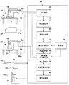
以下、本発明の実施形態について図面を参照して詳細に説明する。図1は、本発明の一実施形態による骨塩定量分析方法を実施するシステムの概略構成を示すものである。本システムは前述したDIP法により骨塩定量分析を行うものであり、図示のように、骨塩定量分析対象の骨部を含む被写体の放射線画像を撮影する第1撮影装置10と、この第1撮影装置10で放射線画像が撮影された記録媒体から放射線画像を読み取って、その放射線画像を示すデジタル画像信号Pcrを出力する読取装置20と、骨塩定量分析対象の骨部を含む被写体の放射線画像を撮影し、直接、その放射線画像を示すデジタル画像信号Pdrを出力する第2撮影装置30と、上記デジタル画像信号PcrあるいはPdrに基づいて分析対象の骨部の骨塩量を求める信号処理装置40と、上記信号処理手段40に各種指示を与えるための入力部50と、骨塩定量分析結果を表示する表示部60とから構成されている。
Hereinafter, embodiments of the present invention will be described in detail with reference to the drawings. FIG. 1 shows a schematic configuration of a system for performing a bone mineral content quantitative analysis method according to an embodiment of the present invention. This system performs bone mineral quantitative analysis by the above-described DIP method. As shown in the figure, the
第1撮影装置10は一例として、特開平8−266529号公報、特開平9−24039号公報等に示される放射線検出体としての蓄積性蛍光体シートに被写体の放射線画像情報を蓄積記録するものであり、ここでは特に、蓄積性蛍光体シートを収容したカセッテ11が用いられる。すなわち本装置10は、カセッテ11が略水平状態に載置される撮影台14と、このカセッテ11に向けて上方から放射線R(一例としてX線)を照射する放射線管球12と、この放射線管球12の駆動を制御する撮影制御部13とを有している。
As an example, the
この第1撮影装置10において、カセッテ11の上に被写体Hが載置された状態下で放射線管球12が駆動され、そこから放射線Rがカセッテ11に向けて照射されると、被写体Hを透過した放射線Rのエネルギーがカセッテ内の蓄積性蛍光体シートに蓄積される。つまり該蓄積性蛍光体シートには、被写体Hの透過放射線画像情報が記録される。
In the
読取装置20は、蓄積性蛍光体シートから上記被写体Hの放射線画像情報を読み取るものである。この種の読取装置については、例えば特開平5−297489号公報等に詳しい記載がなされているが、以下、基本的なことを簡単に説明する。この読取装置20においては、カセッテ11から取り出された蓄積性蛍光体シートがレーザ光等の読取光で2次元走査され、その読取光の照射を受けた蓄積性蛍光体シートの部分から発せられた輝尽発光光が光電変換手段により読み取られて、該シートに記録されていた放射線画像情報を示す画像信号が得られる。この画像信号は、後の信号処理のためにA/D変換処理されて、上記のデジタル画像信号Pcrとされる。
The
第2撮影装置30は、上記第1撮影装置10における放射線管球12、撮影制御部13および撮影台14とそれぞれ同様の放射線管球32、撮影制御部33および撮影台34を有するものであるが、前述のカセッテ11に代えて放射線検出器31に放射線Rが照射されるように構成されている点において第1撮影装置10と基本的に異なっている。上記放射線検出器31は、マトリクス状に配置された画素毎に照射放射線のエネルギーレベルに対応した放射線検出信号を出力するものであり、この検出信号はA/D変換処理され、被写体の透過放射線画像を示すデジタル画像信号Pdrとして出力される。
The
なお、以上のような放射線検出器31としては、例えば特開平7−72253号公報に記載がなされているように、放射線の照射を受けて可視光を発するシンチレータと、その可視光を検出する固体光検出素子とが積層されてなるものや、あるいは例えば特開2010−206067号公報に記載がなされているように、放射線の照射を受けてそのエネルギーに対応した電気信号を出力する放射線光導電層を有してなるものを適用することができる。
As the
信号処理装置40は、上述のデジタル画像信号PcrやPdrが入力される前処理部41と、その後段に順次接続された部位抽出部42、濃度分析部43、管電圧補正部44、撮影装置特性補正部45、骨塩定量分析部46および表示制御部47とを有している。さらにこの信号処理装置40は、上記管電圧補正部44および撮影装置特性補正部45に接続された記憶部48を有している。
The
入力部50は、例えばキーボード51やマウス52等の入力手段を備えてなるものであり、それらの入力手段により、信号処理装置40が行う処理の指示を与える。
The
表示部60は、例えば液晶表示装置やCRT表示装置等の表示手段61からなるものであり、後述のようにして入力される情報に基づいて、骨塩定量分析の結果や、撮影された被写体の放射線画像を必要に応じて表示する。
The
以上述べた信号処理装置40、入力部50および表示部60は、例えば一般的なパーソナルコンピュータ等のコンピュータシステムから構成することができる。
The
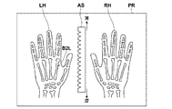
次に図2を参照して、骨塩定量分析のための放射線画像の撮影について説明する。ここではまず、第1撮影装置10における撮影について説明する。この撮影に際しては、蓄積性蛍光体シートを収容したカセッテ11が第1撮影装置10の撮影台14の上に載置され、その上に被検者の左手および右手が置かれ、またそれら両手の間に基準物質としてのアルミスロープが置かれる。このアルミスロープは厚さが連続的に変化するアルミニウム製の板状部材である。なおこの種のアルミスロープに代えて、厚さが段階的に変化するアルミニウム製の板状部材が用いられてもよい。
Next, radiographic imaging for bone mineral quantitative analysis will be described with reference to FIG. Here, first, photographing in the first photographing
この状態で撮影制御部13が操作されることにより放射線管球12が駆動され、そこから発せられた放射線Rが上記左手および右手、並びにアルミスロープを透過してカセッテ11内の蓄積性蛍光体シートに照射される。なおDIP法においては通常、放射線管球12は管電圧を50kVとして撮影を行うようにしており、本実施形態においても撮影制御部13により、管電圧は50kVに設定される。ただし、実効管電圧は経時により低下する傾向があるので、上述のように設定しても実効管電圧が50kVにならないこともある。本実施形態では、そのために分析誤差が生じることを防止するようにしているが、その点に関しては後述する。
The
撮影が終了すると、カセッテ11が第1撮影装置10から取り出されて、読取装置20にセットされる。読取装置20では前述の通りにして、カセッテ11内の蓄積性蛍光体シートからそこに蓄積記録された放射線画像情報が読み取られ、その放射線画像情報を示すデジタル画像信号Pcrが得られる。このデジタル画像信号Pcrが担持する放射線画像は、該信号Pcrを前記表示部60に入力する等により再生表示可能であり、もし表示した場合その放射線画像は図2に示すようなものとなる。すなわちこの放射線画像PRには、被検者の左手LH、右手RHおよびアルミスロープASが記録されている。なおアルミスロープASは、前述のカセッテ11上において、左手LHおよび右手RHの指先方向(図2中で上方)に行くに従って次第に薄くなる状態にしてセットされる。
When the photographing is finished, the
上記デジタル画像信号Pcrは、それを得たカセッテ11を示す識別情報と共に信号処理装置40の前処理部41に入力される。また第1撮影装置10において前述の撮影がなされたとき、撮影制御部13からは第1撮影装置10を示す識別情報、カセッテ11を示す識別情報、撮影順番を示す情報等の撮影情報Scrが、信号処理装置40の撮影装置特性補正部45に入力される。
The digital image signal Pcr is input to the
次に、信号処理装置40における処理について説明する。この信号処理装置40に入力されたデジタル画像信号Pcrは、まず前処理部41において、放射線の照射ムラや、読取装置20の読取特性のムラ等に起因する信号値の変動を補正する処理や、必要に応じて適宜なされるその他の処理を受け、次に部位抽出部42に入力される。
Next, processing in the
部位抽出部42は、デジタル画像信号Pcrが示す画像の中から、画像処理により自動的に、あるいは前記入力部50による指示に基づいて、骨塩定量分析を行う部位を抽出する。DIP法においては通常、図2に示す左手第2中手骨B2Lについて骨塩定量分析を行うようにしているので、本実施形態においても左手第2中手骨B2Lが抽出される。そしてより詳細には、この左手第2中手骨B2Lの全長の中央部分に有るh/10の領域(図3参照)が抽出される。
The
次に濃度分析部43は、上記抽出された領域の平均的な濃度を求める。より具体的にこの濃度分析部43は、上記領域において左手第2中手骨B2Lを横切る方向の濃度プロファイルを求める。この濃度プロファイルは、濃度に代えて輝度を用いて示すと、図4に曲線Qで示すようなものとなる。なお、同図に示すDが骨幅になる。このような濃度プロファイルは、まず上記領域において骨の長さ方向に亘って分布する例えば10数箇所程度について求められ、次にそれらの平均的なプロファイルを演算することによって求められる。
Next, the
従来は、この平均的な濃度プロファイルにおける濃度がそのままアルミスロープの厚さ(アルミ厚)に換算され、つまり放射線画像においてプロファイルの各点濃度と同じ濃度となるアルミスロープ部分の厚さが求められ、そのアルミ厚換算値の積分値(図4における斜線部)ΣGSを骨幅Dで除した値ΣGS/D[単位:mmAL(アルミニウム)]を、骨塩量を示すDIP値としていた。このDIP値については、例えば日本骨代謝学会から性別および年齢層毎の基準値が公表されており、その基準値の100〜80%の範囲に有れば骨塩量は正常範囲にある、といった診断が下されるようになっている。 Conventionally, the density in this average density profile is directly converted into the thickness of the aluminum slope (aluminum thickness), that is, the thickness of the aluminum slope portion that is the same density as each point density of the profile in the radiographic image is obtained, A value ΣGS / D [unit: mmAL (aluminum)] obtained by dividing the integrated value (shaded portion in FIG. 4) ΣGS of the aluminum thickness converted value by the bone width D was used as the DIP value indicating the bone mineral content. About this DIP value, for example, the Japanese bone metabolism society has published a standard value for each gender and age group, and if it is in the range of 100 to 80% of the standard value, the bone mineral content is in the normal range. Diagnosis is to be made.
ただし上記のDIP値=ΣGS/Dは、第1撮影装置10のように蓄積性蛍光体シートを撮影記録媒体とする撮影装置に代えて、蓄積性蛍光体シートとは放射線吸収特性が異なる放射線検出器31を用いる第2撮影装置30が撮影に使用されたり、あるいは実効管電圧が50kV以外になっていた場合は、同じ骨部を撮影しても、以上述べたようにして求められた場合とは異なる値を示すことがある。上に述べた基準値は、蓄積性蛍光体シートを用い、管電圧を50kVに設定して放射線画像を撮影したときのDIP値に対して定められたものであるので、この基準値を適用して骨塩量に関する診断を下すのであれば、上述のように異なる値を示すDIP値を、蓄積性蛍光体シートを用いて管電圧を50kVに設定したときのDIP値に相当するように補正する必要が有る。
However, the above DIP value = ΣGS / D is a radiation detection having a radiation absorption characteristic different from that of the stimulable phosphor sheet, instead of the image sensing device using the stimulable phosphor sheet as an imaging recording medium as in the
以下、その補正について説明する。本発明者は、第1撮影装置10のように蓄積性蛍光体シートに放射線画像を撮影記録する撮影装置においてアルミスロープを撮影したとき、その厚さと、撮影された放射線画像における濃度との関係が、放射線管球の管電圧に応じてどのように変化するか調べた。図5はその結果を示すものであり、これは骨塩定量分析するための放射線画像撮影に先行して、予め求められている。
Hereinafter, the correction will be described. The present inventor, when photographing an aluminum slope in a photographing device that photographs and records a radiation image on a stimulable phosphor sheet like the first photographing
なおこの図5において、横軸がアルミスロープの厚さと一義的に対応するアルミスロープの長手方向位置の座標であり、縦軸が放射線画像における濃度(相対値)である。そしてここに示す10本の特性曲線は、上から順に管電圧が47kV、48kV、49kV、50kV、51kV、52kV、53kV、54kV、55kV、56kVのときのものである。ここに挙げた管電圧の値は、単に撮影制御装置において設定しただけでなく、管電圧計で測定して設定通りの値になっていることを確認したものである。 In FIG. 5, the horizontal axis is the coordinate of the position in the longitudinal direction of the aluminum slope that uniquely corresponds to the thickness of the aluminum slope, and the vertical axis is the density (relative value) in the radiographic image. The ten characteristic curves shown here are obtained when the tube voltages are 47 kV, 48 kV, 49 kV, 50 kV, 51 kV, 52 kV, 53 kV, 54 kV, 55 kV, and 56 kV in order from the top. The tube voltage values listed here are not only set in the imaging control device, but are measured with a tube voltmeter to confirm that the values are as set.
同図に示される通り上記特性曲線の傾き(濃度勾配)は、管電圧の値毎に明確に相違している。このことを利用して本実施形態では、図1の管電圧補正部44がまず、アルミスロープを示すデジタル画像信号Pcrから所定座標間の特性曲線の傾きに基づいて、第1撮影装置10における撮影時の実効管電圧が何kVであったかを求める。そのために記憶部48には、上記傾きと管電圧との対応関係が記憶されており、管電圧補正部44はデジタル画像信号Pcrから求めた傾きに対応する管電圧を読み出す。そして次に管電圧補正部44は、その読み出した管電圧と管電圧50kVとに基づいて、デジタル画像信号Pcrを補正する。なお上記傾きを知るためには、アルミスロープの少なくとも2点に関して前記座標と濃度との関係を求めればよい。
As shown in the figure, the slope (concentration gradient) of the characteristic curve is clearly different for each tube voltage value. In the present embodiment using this, the tube
上記補正は、例えば実効管電圧が48kVであった場合を例に取ると、図6に示すようになされる。すなわち、アルミ厚(もしくは骨部の放射線吸収特性)が図示のようにE1であった場合、管電圧が所定値の50kVであったなら本来画像濃度はDe1’であるところ、実効管電圧が48kVになっているため画像濃度がDe1になっているので、画像濃度De1を示しているデジタル画像信号Pcrを、画像濃度De1’を示す値に補正する。同様にして、例えば画像濃度De2を示しているデジタル画像信号Pcrを、画像濃度De2’を示す値に補正する。この補正前と補正後のデジタル画像信号Pcrの対応関係は、実効管電圧の値毎にLUT(ルックアップテーブル)の形で記憶部48に記憶されており、管電圧補正部44は求めた実効管電圧に関するLUTを参照して、補正後の、つまり補正値とすべきデジタル画像信号Pcrの値を求める。この補正は、前述した平均的な濃度プロファイルを示すデジタル画像信号Pcr、およびアルミスロープの部分を示すデジタル画像信号Pcrに関して全て行われ、その補正後のデジタル画像信号Pcr’が撮影装置特性補正部45に入力される。
For example, when the effective tube voltage is 48 kV, the above correction is performed as shown in FIG. That is, when the aluminum thickness (or the radiation absorption characteristic of the bone part) is E1 as shown in the figure, if the tube voltage is a predetermined value of 50 kV, the effective tube voltage is 48 kV when the original image density is De1 ′. Since the image density is De1, the digital image signal Pcr indicating the image density De1 is corrected to a value indicating the image density De1 ′. Similarly, for example, the digital image signal Pcr indicating the image density De2 is corrected to a value indicating the image density De2 '. The correspondence between the digital image signal Pcr before and after the correction is stored in the
前述した通り撮影装置特性補正部45には、第1撮影装置10の撮影制御部13から、第1撮影装置10を示す識別情報、カセッテ11を示す識別情報、撮影順番を示す情報等の撮影情報Scrが入力されている。撮影装置特性補正部45はこの撮影情報Scrに基づいて、あるいはデジタル画像信号Pcrに付帯された撮影情報に基づいて、入力されたデジタル画像信号Pcr’の元のデジタル画像信号Pcrが第1撮影装置10で生成されたものであると判別した場合は、入力されたデジタル画像信号Pcr’を素通りさせて骨塩定量分析部46に入力させる。
As described above, the photographing apparatus
骨塩定量分析部46は入力されたデジタル画像信号Pcr’から前述のDIP値=ΣGS/Dを求める。すなわち骨塩定量分析部46は、デジタル画像信号Pcr’が示す平均的な濃度プロファイル(図4のQ)における濃度をアルミスロープの厚さ(アルミ厚)に換算し、そのアルミ厚換算値の積分値ΣGSを骨幅Dで除した値ΣGS/DをDIP値とする。骨塩定量分析部46は、こうして求めたDIP値=ΣGS/Dを示す情報を表示制御部47に入力する。表示制御部47はこのDIP値を表示部60の表示手段61において表示させる。
The bone mineral
以上のようにして表示手段61に表示されるDIP値は、管電圧補正部44による補正がなされた後のデジタル画像信号Pcr’に基づくものであるから、管電圧を50kVに設定して得られたときのDIP値と等しくなる。よって、前述の基準値を利用してなされる骨塩量に関する診断も、信頼性が高いものとなり得る。なお表示部60の表示手段61においては、DIP値の表示だけでなく、上記基準値との比較に基づく診断結果の表示、例えば基準値に対する比率の表示や、「骨粗鬆症の心配はありません」等の表示を併せて行うようにしてもよい。
The DIP value displayed on the display means 61 as described above is based on the digital image signal Pcr ′ after the correction by the tube
ここで、上記デジタル画像信号Pcrをデジタル画像信号Pcr’に補正する代わりに、まずデジタル画像信号Pcrに基づいてDIP値=ΣGS/Dを求め、その求められたDIP値を、デジタル画像信号Pcr’から求められるDIP値に相当するように補正してもよい。 Here, instead of correcting the digital image signal Pcr to the digital image signal Pcr ′, first, DIP value = ΣGS / D is obtained based on the digital image signal Pcr, and the obtained DIP value is obtained as the digital image signal Pcr ′. You may correct | amend so that it may correspond to the DIP value calculated | required from.
なお、先に述べた基準値は、蓄積性蛍光体シートを用い、管電圧を50kVに設定して撮影したときのDIP値に対して定められたものであるので、蓄積性蛍光体シートを用いる第1撮影装置10で放射線画像を撮影した場合は、装置間の特性の違いによるDIP値の相違については考慮する必要がない。そこでこの場合は前述した通り、デジタル画像信号Pcr’を撮影装置特性補正部45は素通りさせているものである。また、実効管電圧が50kVであると認められた場合も、管電圧の違いによるDIP値の相違を補正する処理は不要であるので、管電圧補正部44における上述の補正はなされない。
In addition, since the reference value described above is determined with respect to the DIP value when the tube voltage is set to 50 kV using the stimulable phosphor sheet, the stimulable phosphor sheet is used. When a radiographic image is captured by the
次に、図1の第2撮影装置30を用いて放射線画像を撮影した場合に、信号処理装置40でなされる処理等について説明する。まず、この撮影がなされた場合、第2撮影装置30が出力するデジタル画像信号Pdrは前処理部41に入力され、そこで前述と同様の処理を受ける。またこの撮影がなされたとき、撮影制御部33からは、前述の撮影情報Scrと同様の撮影情報Sdrが撮影装置特性補正部45に入力される。
Next, processing performed by the
そしてこの場合も、管電圧補正部44において、実効管電圧が50kVになっていなかったことが検出されると、第1撮影装置10により放射線画像を撮影した場合と同様の補正処理がなされる。この管電圧補正部44による補正処理は前述と同じものであるので、ここでは詳しい説明を省略する。なお図1においては、第2撮影装置30から出力されたデジタル画像信号Pdrが上記補正処理を受けた場合、その処理済みのデジタル画像信号をPdr’と表している。
In this case as well, when the tube
ただし、図5に示したような座標と濃度との関係は、撮影装置毎に固有のものとなるので、第2撮影装置30によって撮影を行った場合のこの関係を図8に示す。ここで第2撮影装置30の放射線検出器31は、GoS(ガドリニウムオキサイドサルファ)からなるシンチレータおよび固体光検出素子が積層されてなるものである。なお、図1には示していないが、上述のような放射線検出器として、CsI(ヨウ化セシウム)からなるシンチレータおよび固体光検出素子が積層されてなるものも適用可能であり、その種の放射線検出器が適用された撮影装置を以下、第3撮影装置と称することとする。図9には、そのような第3撮影装置で撮影を行った場合の、上記座標と濃度との関係を示してある。
However, since the relationship between the coordinates and the density as shown in FIG. 5 is unique to each photographing apparatus, this relation when photographing by the second photographing
一方、本発明者は、ある共通の骨部(これは一定の厚さを持つアルミニウム板材に代えられてもよい)の放射線画像を第1撮影装置10および第2撮影装置30により管電圧を種々に変えて撮影し、その撮影された骨部について前述のDIP値=ΣGS/Dを求めた。図7はその結果を示すものである。この場合、DIP値は前述した通り撮影時の管電圧の値に応じて変化するが、図示されるようにその変化特性は、撮影装置毎に異なっていることが分かった。なお同図において、第1撮影装置10により撮影を行った場合の特性がA、第2撮影装置30で撮影を行った場合の特性がB、そして前記第3撮影装置で撮影を行ったときの特性がCである。
On the other hand, the inventor of the present invention uses a
本実施形態においては、撮影時の管電圧を50kVに設定した場合のΣGS/D値を求めるようにしているので、図7において、この管電圧が50kVのときの各ΣGS/D値に着目すると、共通の骨部を撮影しているのにも拘わらず、撮影装置毎にΣGS/D値が異なっている。これは、上記蓄積性蛍光体シートや、放射線検出器31等の2種の放射線検出器における放射線吸収特性が互いに異なることに起因している。
In the present embodiment, the ΣGS / D value when the tube voltage at the time of photographing is set to 50 kV is obtained. Therefore, in FIG. 7, when attention is paid to each ΣGS / D value when the tube voltage is 50 kV. The ΣGS / D value is different for each photographing apparatus, although the common bone part is photographed. This is due to the fact that the radiation absorption characteristics of the stimulable phosphor sheet and the two types of radiation detectors such as the
ここで、図7の特性が得られた骨部とは異なる骨部を撮影した場合も、管電圧が50kVのときの3つのΣGS/D値の間の比率は、図7の特性における比率と略同じになると考えられる。また、ΣGS/D値は画像濃度と対応している。以上のことに鑑みて図1の撮影装置特性補正部45は、入力されたデジタル画像信号Pdr’の元になるデジタル画像信号Pdrが、第2撮影装置30での撮影により得られたものであると判別した場合は、デジタル画像信号Pdr’のうちアルミスロープASの部分に関する信号を、それが示す濃度Dd’が濃度Dd”=kDd’となるように変換する。なおkは、図7において管電圧が50kVのときの特性BにおけるΣGS/D値に対する、特性AにおけるΣGS/D値の比率である。なお上記の判別は、撮影制御部33から撮影装置特性補正部45に入力される撮影情報Sdrや、あるいはデジタル画像信号Pdrに付帯される撮影情報等に基づいて行うことができる。
Here, even when a bone part different from the bone part from which the characteristic of FIG. 7 is obtained is photographed, the ratio between the three ΣGS / D values when the tube voltage is 50 kV is the ratio in the characteristic of FIG. It will be almost the same. The ΣGS / D value corresponds to the image density. In view of the above, the imaging device
上述した変換処理がなされた後のデジタル画像信号Pdr”は、骨塩定量分析部46に入力される。骨塩定量分析部46ではこのデジタル画像信号Pdr”に基づいて、前述と同様にしてDIP値=ΣGS/Dが求められ、表示制御部47はこのDIP値を表示部60の表示手段61において表示させる。なお上記の変換処理は、処理の都度演算を行って実行してもよいし、あるいは変換処理の前後の信号値の組合せをLUTの形で記憶手段に記憶しておき、そのLUTを参照して実行してもよい。
The digital image signal Pdr ″ after the above-described conversion processing is input to the bone mineral
また、デジタル画像信号Pdr’のうちアルミスロープASの部分に関する信号を上記のように変換する代わりに、同じ効果が得られるように、反対に、デジタル画像信号Pdr’のうち左手第2中手骨B2Lに関する信号だけを変換処理するようにしてもよい。またこのような変換処理は、アルミスロープASまたは左手第2中手骨B2Lの濃度プロファイルを抽出してから、その濃度プロファイルを示すデジタル画像信号Pdr’に対して施してもよいし、あるいは、抽出前の画像内該当エリアのデジタル画像信号Pdr’に対して施してもよい。 On the other hand, in order to obtain the same effect instead of converting the signal related to the aluminum slope AS in the digital image signal Pdr ′ as described above, the left hand second metacarpal in the digital image signal Pdr ′ is reversed. Only the signal related to B2L may be converted. Further, such conversion processing may be performed on the digital image signal Pdr ′ indicating the density profile after extracting the density profile of the aluminum slope AS or the left second metacarpal bone B2L, or may be extracted. You may perform with respect to digital image signal Pdr 'of the applicable area in a previous image.
こうして表示部60に表示されるDIP値は、上記の変換処理がなされていることにより、撮影対象が同じ骨部であれば、第1撮影装置10により放射線画像の撮影がなされた場合の値と同じ値となる。そこで、前述の基準値を利用してなされる骨塩量に関する診断も、信頼性が高いものとなり得る。
In this way, the DIP value displayed on the
ここで本実施形態では、デジタル画像信号Pdr’をデジタル画像信号Pdr”に変換し、その変換後のデジタル画像信号Pdr”からDIP値=ΣGS/Dを求めるようにしているが、デジタル画像信号Pdr’からDIP値=ΣGS/Dを求め、その求められたDIP値=ΣGS/Dを図7の関係に基づいて、第1撮影装置10により撮影した場合のDIP値に相当するように変換処理しても構わない。
In this embodiment, the digital image signal Pdr ′ is converted into the digital image signal Pdr ″, and the DIP value = ΣGS / D is obtained from the converted digital image signal Pdr ″. DIP value = ΣGS / D is obtained from “,” and the obtained DIP value = ΣGS / D is converted based on the relationship shown in FIG. 7 so as to correspond to the DIP value when the first photographing
また、管電圧補正部44による補正と撮影装置特性補正部45による補正を双方とも行う場合のために、それら双方の補正を同時に行うための変換値を規定したLUTを作成して記憶手段に記憶させておき、そのLUTを用いて上記双方の補正を一度に行うようにしてもよい。
Further, in order to perform both the correction by the tube
なお、前述した第3撮影装置により放射線画像の撮影がなされた場合も、そこから出力されて前処理部41に入力され、必要に応じて管電圧補正処理を受けた後のデジタル画像信号に対して、上記デジタル画像信号Pdr’をデジタル画像信号Pdr”に変換した処理と同様の変換処理を施せばよい。ただしその場合は、前記kの値として、図7において管電圧が50kVのときの特性CにおけるΣGS/D値に対する、特性AにおけるΣGS/D値の比率を適用する。
Even when a radiographic image is captured by the third imaging device described above, the digital image signal output from the radiographic image is input to the
また、以上説明した本発明の骨塩定量分析方法を実施する各手順を有するプログラムをコンピュータ読取り可能な記録媒体に記録しておき、その記録媒体を用いて各手順をコンピュータに実行させることも可能である。 It is also possible to record a program having each procedure for carrying out the bone mineral content quantitative analysis method of the present invention described above on a computer-readable recording medium and cause the computer to execute each procedure using the recording medium. It is.
10 第1撮影装置
11 カセッテ
12、32 放射線管球
13、33 撮影制御部
14、34 撮影台
20 読取装置
30 第2撮影装置
40 信号処理装置
41 前処理部
42 部位抽出部
43 濃度分析部
44 管電圧補正部
45 撮影装置特性補正部
46 骨塩定量分析部
47 表示制御部
48 記憶部
50 入力部
60 表示部
DESCRIPTION OF
Claims (11)
前記骨部および標準物質を透過した放射線を放射線検出体で検出して該骨部および標準物質を示す放射線画像を得、
この放射線画像において、分析対象の骨部と同じ濃度を示す標準物質の部分の放射線透過特性に基づいて該骨部の骨塩定量を求める骨塩定量分析方法において、
骨塩定量を求めるのに先行して撮影条件を、基準撮影条件を含む複数条件に順次変え、その都度前記標準物質の放射線画像を得、
これらの放射線画像から、標準物質の放射線透過特性が互いに異なる少なくとも2つの部分に関する濃度勾配を、前記複数通りの撮影条件毎に求めておき、
骨塩定量を求めるために撮影された放射線画像において、前記濃度勾配から、その放射線画像が基準撮影条件ではない撮影条件で撮影されたものと判別されるとき、その濃度勾配と、基準撮影条件で撮影された場合の前記濃度勾配との関係に基づいて、骨塩定量分析に供される放射線画像を示す画像信号および/または骨塩定量分析結果を、基準撮影条件で撮影された場合のものに相当するように補正することを特徴とする骨塩定量分析方法。 Radiation generated from a radiation tube is simultaneously irradiated to a bone part to be analyzed and a standard substance having a plurality of parts having different radiation transmission characteristics,
Radiation that has passed through the bone part and the standard substance is detected by a radiation detector to obtain a radiographic image showing the bone part and the standard substance,
In this radiographic image, in the bone mineral content quantitative analysis method for determining the bone mineral content of the bone portion based on the radiation transmission characteristics of the portion of the standard substance showing the same concentration as the bone portion to be analyzed,
Prior to determining bone mineral content, the imaging conditions are sequentially changed to a plurality of conditions including the reference imaging conditions, and each time a radiographic image of the standard substance is obtained,
From these radiation images, a concentration gradient relating to at least two portions having different radiation transmission characteristics of the standard substance is obtained for each of the plurality of imaging conditions,
In a radiographic image taken to determine bone mineral content, when it is determined from the density gradient that the radiographic image was taken under imaging conditions other than the standard imaging conditions, the density gradient and the standard imaging conditions are used. Based on the relationship with the concentration gradient when imaged, the image signal indicating the radiographic image used for bone mineral quantitative analysis and / or the bone mineral quantitative analysis result is converted to that when imaged under the standard imaging conditions. A method for quantitative analysis of bone mineral, which is corrected so as to correspond.
前記骨部および標準物質を透過した放射線を放射線検出体で検出して該骨部および標準物質を示す放射線画像を得、
この放射線画像において、分析対象の骨部と同じ濃度を示す標準物質の部分の放射線透過特性に基づいて該骨部の骨塩定量を求める骨塩定量分析方法において、
骨塩定量を求めるのに先行して前記放射線管球を、基準管電圧を含む複数通りの管電圧で駆動して、各駆動の都度前記標準物質の放射線画像を得、
これらの放射線画像から、標準物質の放射線透過特性が互いに異なる少なくとも2つの部分に関する濃度勾配を、前記複数通りの管電圧毎に求めておき、
骨塩定量を求めるために撮影された放射線画像において、前記濃度勾配から、その放射線画像が基準管電圧ではない管電圧で撮影されたものと判別されるとき、その濃度勾配と、基準管電圧で撮影された場合の前記濃度勾配との関係に基づいて、骨塩定量分析に供される放射線画像を示す画像信号および/または骨塩定量分析結果を、基準管電圧で撮影された場合のものに相当するように補正することを特徴とする骨塩定量分析方法。 Radiation generated from a radiation tube is simultaneously irradiated to a bone part to be analyzed and a standard substance having a plurality of parts having different radiation transmission characteristics,
Radiation that has passed through the bone part and the standard substance is detected by a radiation detector to obtain a radiographic image showing the bone part and the standard substance,
In this radiographic image, in the bone mineral content quantitative analysis method for determining the bone mineral content of the bone portion based on the radiation transmission characteristics of the portion of the standard substance showing the same concentration as the bone portion to be analyzed,
Prior to determining bone mineral content, the radiation tube is driven with a plurality of tube voltages including a reference tube voltage, and a radiographic image of the standard substance is obtained for each drive,
From these radiation images, a concentration gradient relating to at least two portions having different radiation transmission characteristics of the standard substance is obtained for each of the plurality of tube voltages,
In the radiographic image taken to determine the bone mineral content, when it is determined from the concentration gradient that the radiographic image was taken at a tube voltage other than the reference tube voltage, the concentration gradient and the reference tube voltage are used. Based on the relationship with the concentration gradient when imaged, the image signal indicating the radiographic image used for bone mineral quantitative analysis and / or the bone mineral quantitative analysis result is converted to that when imaged at the reference tube voltage. A method for quantitative analysis of bone mineral, which is corrected so as to correspond.
それらの中の1つの特定放射線検出体以外の放射線検出体が用いられる場合は、骨塩定量分析に供される放射線画像を示す画像信号および/または骨塩定量分析結果を、前記特定放射線検出体を適用した場合のものに相当するように補正することを特徴とする請求項1から5いずれか1項記載の骨塩定量分析方法。 A plurality of types of radiation detectors having different radiation absorption characteristics can be applied as the radiation detector,
When a radiation detector other than one of the specific radiation detectors is used, an image signal and / or a bone mineral quantitative analysis result indicating a radiological image to be subjected to bone mineral quantitative analysis are used as the specific radiation detector. The bone mineral content quantitative analysis method according to any one of claims 1 to 5, wherein the bone mineral density analysis method is corrected so as to correspond to a case in which the above is applied.
前記放射線画像において、分析対象の骨部と同じ濃度を示す標準物質の部分の放射線透過特性に基づいて該骨部の骨塩定量を求める信号処理手段とを備えてなる骨塩定量分析システムにおいて、
骨塩定量を求めるのに先行して撮影条件を、基準撮影条件を含む複数条件に順次変え、その都度前記標準物質の放射線画像を得た際に、これらの放射線画像から前記複数通りの撮影条件毎に求められた、標準物質の放射線透過特性が互いに異なる少なくとも2つの部分に関する濃度勾配を記憶した記憶手段と、
骨塩定量を求めるために撮影された放射線画像において、前記濃度勾配から、その放射線画像が基準撮影条件ではない撮影条件で撮影されたものと判別されるとき、その濃度勾配と、基準撮影条件で撮影された場合の前記濃度勾配との関係に基づいて、骨塩定量分析に供される放射線画像を示す画像信号および/または骨塩定量分析結果を、基準撮影条件で撮影された場合のものに相当するように補正する補正手段とが設けられたことを特徴とする骨塩定量分析システム。 Radiation generated from a radiation tube is simultaneously irradiated to a bone part to be analyzed and a standard substance having a plurality of parts having different radiation transmission characteristics, and radiation that has passed through the bone part and the standard substance is detected as a radiation detector. A radiographic imaging device that obtains a radiographic image showing the bone and the standard substance by detecting with
In the radiographic image, in the bone mineral content quantitative analysis system comprising signal processing means for determining the bone mineral content of the bone portion based on the radiation transmission characteristics of the portion of the standard substance showing the same concentration as the bone portion to be analyzed,
Prior to determining bone mineral content, the imaging conditions are sequentially changed to a plurality of conditions including the reference imaging conditions, and each time a radiographic image of the standard substance is obtained, the plurality of imaging conditions are obtained from these radiographic images. Storage means for storing concentration gradients relating to at least two portions having different radiation transmission characteristics of the standard substance, which are obtained for each of the standards,
In a radiographic image taken to determine bone mineral content, when it is determined from the density gradient that the radiographic image was taken under imaging conditions other than the standard imaging conditions, the density gradient and the standard imaging conditions are used. Based on the relationship with the concentration gradient when imaged, the image signal indicating the radiographic image used for bone mineral quantitative analysis and / or the bone mineral quantitative analysis result is converted to that when imaged under the standard imaging conditions. A bone mineral content quantitative analysis system characterized by comprising correction means for correcting the corresponding amount.
前記放射線画像において、分析対象の骨部と同じ濃度を示す標準物質の部分の放射線透過特性に基づいて該骨部の骨塩定量を求める信号処理手段とを備えてなる骨塩定量分析システムにおいて、
骨塩定量を求めるのに先行して前記放射線管球を、基準管電圧を含む複数通りの管電圧で駆動して、各駆動の都度前記標準物質の放射線画像を得た際に、これらの放射線画像から前記複数通りの管電圧毎に求められた、標準物質の放射線透過特性が互いに異なる少なくとも2つの部分に関する濃度勾配を記憶した記憶手段と、
骨塩定量を求めるために撮影された放射線画像において、前記濃度勾配から、その放射線画像が基準管電圧ではない管電圧で撮影されたものと判別されるとき、その濃度勾配と、基準管電圧で撮影された場合の前記濃度勾配との関係に基づいて、骨塩定量分析に供される放射線画像を示す画像信号および/または骨塩定量分析結果を、基準管電圧で撮影された場合のものに相当するように補正する補正手段とが設けられたことを特徴とする骨塩定量分析システム。 Radiation generated from a radiation tube is simultaneously irradiated to a bone part to be analyzed and a standard substance having a plurality of parts having different radiation transmission characteristics, and radiation that has passed through the bone part and the standard substance is detected as a radiation detector. A radiographic imaging device that obtains a radiographic image showing the bone and the standard substance by detecting with
In the radiographic image, in the bone mineral content quantitative analysis system comprising signal processing means for determining the bone mineral content of the bone portion based on the radiation transmission characteristics of the portion of the standard substance showing the same concentration as the bone portion to be analyzed,
Prior to determining the bone mineral content, the radiation tube is driven with a plurality of tube voltages including a reference tube voltage, and each time each drive is performed, a radiation image of the standard substance is obtained. Storage means for storing concentration gradients relating to at least two portions having different radiation transmission characteristics of the standard substance, obtained from the image for each of the plurality of tube voltages;
In the radiographic image taken to determine the bone mineral content, when it is determined from the concentration gradient that the radiographic image was taken at a tube voltage other than the reference tube voltage, the concentration gradient and the reference tube voltage are used. Based on the relationship with the concentration gradient when imaged, the image signal indicating the radiographic image used for bone mineral quantitative analysis and / or the bone mineral quantitative analysis result is converted to that when imaged at the reference tube voltage. A bone mineral content quantitative analysis system characterized by comprising correction means for correcting the corresponding amount.
前記骨部および標準物質を透過した放射線を放射線検出体で検出して該骨部および標準物質を示す放射線画像を得、
この放射線画像において、分析対象の骨部と同じ濃度を示す標準物質の部分の放射線透過特性に基づいて該骨部の骨塩定量を求める骨塩定量分析方法をコンピュータに実行させるためのプログラムを記録したコンピュータ読取り可能な記録媒体であって、
骨塩定量を求めるのに先行して撮影条件を、基準撮影条件を含む複数条件に順次変え、その都度前記標準物質の放射線画像を得る手順と、
これらの放射線画像から、標準物質の放射線透過特性が互いに異なる少なくとも2つの部分に関する濃度勾配を、前記複数通りの撮影条件毎に求める手順と、
骨塩定量を求めるために撮影された放射線画像において、前記濃度勾配から、その放射線画像が基準撮影条件ではない撮影条件で撮影されたものと判別されるとき、その濃度勾配と、基準撮影条件で撮影された場合の前記濃度勾配との関係に基づいて、骨塩定量分析に供される放射線画像を示す画像信号および/または骨塩定量分析結果を、基準撮影条件で撮影された場合のものに相当するように補正する手順とを記録していることを特徴とするコンピュータ読取り可能な記録媒体。 Radiation generated from a radiation tube is simultaneously irradiated to a bone part to be analyzed and a standard substance having a plurality of parts having different radiation transmission characteristics,
Radiation that has passed through the bone part and the standard substance is detected by a radiation detector to obtain a radiographic image showing the bone part and the standard substance,
In this radiographic image, a program for causing a computer to execute a bone mineral quantitative analysis method for determining bone mineral content in a bone based on the radiation transmission characteristics of a reference material portion having the same concentration as the bone to be analyzed is recorded. A computer-readable recording medium,
Prior to obtaining bone mineral content determination, the imaging conditions are sequentially changed to a plurality of conditions including reference imaging conditions, and each time a procedure for obtaining a radiographic image of the standard substance,
From these radiographic images, a procedure for obtaining a concentration gradient for at least two portions having different radiation transmission characteristics of the standard substance for each of the plurality of imaging conditions;
In a radiographic image taken to determine bone mineral content, when it is determined from the density gradient that the radiographic image was taken under imaging conditions other than the standard imaging conditions, the density gradient and the standard imaging conditions are used. Based on the relationship with the concentration gradient when imaged, the image signal indicating the radiographic image used for bone mineral quantitative analysis and / or the bone mineral quantitative analysis result is converted to that when imaged under the standard imaging conditions. A computer-readable recording medium having recorded therein a procedure for correcting so as to correspond.
前記骨部および標準物質を透過した放射線を放射線検出体で検出して該骨部および標準物質を示す放射線画像を得、
この放射線画像において、分析対象の骨部と同じ濃度を示す標準物質の部分の放射線透過特性に基づいて該骨部の骨塩定量を求める骨塩定量分析方法をコンピュータに実行させるためのプログラムを記録したコンピュータ読取り可能な記録媒体であって、
骨塩定量を求めるのに先行して前記放射線管球を、基準管電圧を含む複数通りの管電圧で駆動して、各駆動の都度前記標準物質の放射線画像を得る手順と、
これらの放射線画像から、標準物質の放射線透過特性が互いに異なる少なくとも2つの部分に関する濃度勾配を、前記複数通りの管電圧毎に求める手順と、
骨塩定量を求めるために撮影された放射線画像において、前記濃度勾配から、その放射線画像が基準管電圧ではない管電圧で撮影されたものと判別されるとき、その濃度勾配と、基準管電圧で撮影された場合の前記濃度勾配との関係に基づいて、骨塩定量分析に供される放射線画像を示す画像信号および/または骨塩定量分析結果を、基準管電圧で撮影された場合のものに相当するように補正する手順とを記録していることを特徴とするコンピュータ読取り可能な記録媒体。 Radiation generated from a radiation tube is simultaneously irradiated to a bone part to be analyzed and a standard substance having a plurality of parts having different radiation transmission characteristics,
Radiation that has passed through the bone part and the standard substance is detected by a radiation detector to obtain a radiographic image showing the bone part and the standard substance,
In this radiographic image, a program for causing a computer to execute a bone mineral quantitative analysis method for determining bone mineral content in a bone based on the radiation transmission characteristics of a reference material portion having the same concentration as the bone to be analyzed is recorded. A computer-readable recording medium,
Prior to determining bone mineral content, the radiation tube is driven with a plurality of tube voltages including a reference tube voltage, and a radiographic image of the standard substance is obtained for each drive; and
From these radiographic images, a procedure for obtaining a concentration gradient for at least two portions having different radiation transmission characteristics of the standard substance for each of the plurality of tube voltages;
In the radiographic image taken to determine the bone mineral content, when it is determined from the concentration gradient that the radiographic image was taken at a tube voltage other than the reference tube voltage, the concentration gradient and the reference tube voltage are used. Based on the relationship with the concentration gradient when imaged, the image signal indicating the radiographic image used for bone mineral quantitative analysis and / or the bone mineral quantitative analysis result is converted to that when imaged at the reference tube voltage. A computer-readable recording medium having recorded therein a procedure for correcting so as to correspond.
Priority Applications (2)
| Application Number | Priority Date | Filing Date | Title |
|---|---|---|---|
| JP2012040892A JP5486620B2 (en) | 2011-12-28 | 2012-02-28 | Bone mineral quantitative analysis method, bone mineral quantitative analysis system, and recording medium |
| US13/722,994 US8989346B2 (en) | 2011-12-28 | 2012-12-20 | Bone mineral density analysis method, bone mineral density analysis apparatus, and recording medium |
Applications Claiming Priority (3)
| Application Number | Priority Date | Filing Date | Title |
|---|---|---|---|
| JP2011287749 | 2011-12-28 | ||
| JP2011287749 | 2011-12-28 | ||
| JP2012040892A JP5486620B2 (en) | 2011-12-28 | 2012-02-28 | Bone mineral quantitative analysis method, bone mineral quantitative analysis system, and recording medium |
Publications (3)
| Publication Number | Publication Date |
|---|---|
| JP2013150762A JP2013150762A (en) | 2013-08-08 |
| JP2013150762A5 JP2013150762A5 (en) | 2013-09-26 |
| JP5486620B2 true JP5486620B2 (en) | 2014-05-07 |
Family
ID=48694797
Family Applications (1)
| Application Number | Title | Priority Date | Filing Date |
|---|---|---|---|
| JP2012040892A Active JP5486620B2 (en) | 2011-12-28 | 2012-02-28 | Bone mineral quantitative analysis method, bone mineral quantitative analysis system, and recording medium |
Country Status (2)
| Country | Link |
|---|---|
| US (1) | US8989346B2 (en) |
| JP (1) | JP5486620B2 (en) |
Families Citing this family (10)
| Publication number | Priority date | Publication date | Assignee | Title |
|---|---|---|---|---|
| WO2015011889A1 (en) * | 2013-07-23 | 2015-01-29 | 富士フイルム株式会社 | Radiation-image processing device and method |
| US9848818B1 (en) * | 2013-08-09 | 2017-12-26 | O.N.Diagnostics, LLC | Clinical assessment of fragile bone strength |
| US11850061B2 (en) * | 2013-08-09 | 2023-12-26 | O.N.Diagnostics, LLC | Clinical assessment of fragile bone strength |
| JP6291810B2 (en) * | 2013-11-27 | 2018-03-14 | コニカミノルタ株式会社 | Medical image processing device |
| JP6291809B2 (en) * | 2013-11-27 | 2018-03-14 | コニカミノルタ株式会社 | Medical image processing device |
| US10667777B2 (en) * | 2014-11-06 | 2020-06-02 | University Of Utah Research Foundation | Radiograph density detection device |
| JP6676337B2 (en) | 2015-10-30 | 2020-04-08 | キヤノン株式会社 | Radiation imaging system, radiation image information processing apparatus, radiation image information processing method, and program therefor |
| JP6676338B2 (en) | 2015-10-30 | 2020-04-08 | キヤノン株式会社 | Radiation imaging system, radiation image information processing apparatus, radiation image information processing method, and program therefor |
| JP6662699B2 (en) * | 2016-04-26 | 2020-03-11 | キヤノンメディカルシステムズ株式会社 | Medical image processing equipment |
| JP2022011814A (en) | 2020-06-30 | 2022-01-17 | キヤノン株式会社 | Radiation imaging system, control device, control method of radiation imaging system and program |
Family Cites Families (14)
| Publication number | Priority date | Publication date | Assignee | Title |
|---|---|---|---|---|
| IL79733A (en) * | 1986-08-15 | 1990-04-29 | Elscint Ltd | Bone mineral density mapping |
| US5379997A (en) | 1992-03-31 | 1995-01-10 | Fuji Photo Film Co., Ltd. | Cassette |
| JPH0772253A (en) | 1993-09-01 | 1995-03-17 | Fuji Photo Film Co Ltd | Method for reading radiation image signal and radiation detector used therefor |
| JP2983421B2 (en) * | 1993-11-26 | 1999-11-29 | 帝人株式会社 | Bone measurement method and device |
| JPH08266529A (en) | 1995-03-31 | 1996-10-15 | Fuji Photo Film Co Ltd | Quantitative analysis of osteosalt |
| JPH0924039A (en) | 1995-07-10 | 1997-01-28 | Fuji Photo Film Co Ltd | Bone-salt quantitative analysis method and device |
| JP3256667B2 (en) * | 1997-01-10 | 2002-02-12 | アロカ株式会社 | X-ray measurement device |
| JP2004113587A (en) * | 2002-09-27 | 2004-04-15 | Aloka Co Ltd | X-ray measuring apparatus |
| TWI256473B (en) * | 2003-08-27 | 2006-06-11 | Ind Tech Res Inst | Biosensor and method for bone mineral density measurement |
| JP2006334046A (en) * | 2005-06-01 | 2006-12-14 | Canon Inc | Radiographic equipment and radiographing method |
| US7746976B2 (en) * | 2005-12-30 | 2010-06-29 | Carestream Health, Inc. | Bone mineral density assessment using mammography system |
| JPWO2008044439A1 (en) | 2006-10-06 | 2010-02-04 | コニカミノルタエムジー株式会社 | Bone mineral content measuring device |
| JP2010200824A (en) | 2009-02-27 | 2010-09-16 | Fujifilm Corp | Image forming apparatus |
| JP2010206067A (en) | 2009-03-05 | 2010-09-16 | Fujifilm Corp | Radiation detector |
-
2012
- 2012-02-28 JP JP2012040892A patent/JP5486620B2/en active Active
- 2012-12-20 US US13/722,994 patent/US8989346B2/en active Active
Also Published As
| Publication number | Publication date |
|---|---|
| JP2013150762A (en) | 2013-08-08 |
| US20130170614A1 (en) | 2013-07-04 |
| US8989346B2 (en) | 2015-03-24 |
Similar Documents
| Publication | Publication Date | Title |
|---|---|---|
| JP5486620B2 (en) | Bone mineral quantitative analysis method, bone mineral quantitative analysis system, and recording medium | |
| JP5089210B2 (en) | Image sensor image processing method | |
| KR100738943B1 (en) | Radiographic apparatus and radiographic method | |
| JP6363573B2 (en) | Radiation source image plane distance acquisition apparatus, method and program, and radiographic image processing apparatus, method and program | |
| JP5224898B2 (en) | Radiation imaging apparatus and driving method thereof | |
| EP2702449B1 (en) | System and method for correction of geometric distortion of multi-camera flat panel x-ray detectors | |
| US20140077086A1 (en) | System and method for linearization of multi-camera flat panel x-ray detectors | |
| US20170065244A1 (en) | Radiographic image processing apparatus and method and recording medium storing therein radiographic image processing program | |
| JP2010042150A (en) | Radiographic apparatus | |
| JP2008018047A (en) | Defective area correction apparatus, method and program, and radiation detector | |
| EP2716221A1 (en) | Method and device for obtaining radiation dose, and radiographic image pickup system | |
| KR101037882B1 (en) | Edge evaluation method, edge detection method, image correction method, and image processing system | |
| JP2009201586A (en) | Radiographic apparatus | |
| JP2008220724A (en) | X-ray imaging system | |
| JP4908283B2 (en) | Radiation image capturing apparatus and pixel defect information acquisition method | |
| JP5599831B2 (en) | Method for identifying analysis target site in quantitative analysis of bone mineral, image processing apparatus and recording medium for implementing this method | |
| JP2009201552A (en) | Radiographic apparatus | |
| JP2009201587A (en) | Radiographic apparatus | |
| JP4839122B2 (en) | X-ray diagnostic imaging equipment | |
| JP5448676B2 (en) | Radiography management system | |
| JP2015080518A (en) | Radiation imaging device and method for controlling the same, radiation image processing device and method, program and computer readable storage medium | |
| JPWO2007049348A1 (en) | Radiation imaging apparatus and radiation detection signal processing method | |
| JP2005051702A (en) | Medical image information processing method, medical image information processor, and medical image information processing system | |
| JP2007275196A (en) | Optical or radiological image displaying device and optical or radiographic imaging apparatus equipped with it | |
| JP5456404B2 (en) | Defective pixel detection method and image processing apparatus |
Legal Events
| Date | Code | Title | Description |
|---|---|---|---|
| A521 | Request for written amendment filed |
Free format text: JAPANESE INTERMEDIATE CODE: A523 Effective date: 20130708 |
|
| A621 | Written request for application examination |
Free format text: JAPANESE INTERMEDIATE CODE: A621 Effective date: 20130708 |
|
| A977 | Report on retrieval |
Free format text: JAPANESE INTERMEDIATE CODE: A971007 Effective date: 20140124 |
|
| TRDD | Decision of grant or rejection written | ||
| A01 | Written decision to grant a patent or to grant a registration (utility model) |
Free format text: JAPANESE INTERMEDIATE CODE: A01 Effective date: 20140218 |
|
| A61 | First payment of annual fees (during grant procedure) |
Free format text: JAPANESE INTERMEDIATE CODE: A61 Effective date: 20140221 |
|
| R150 | Certificate of patent or registration of utility model |
Ref document number: 5486620 Country of ref document: JP Free format text: JAPANESE INTERMEDIATE CODE: R150 |
|
| R250 | Receipt of annual fees |
Free format text: JAPANESE INTERMEDIATE CODE: R250 |
|
| R250 | Receipt of annual fees |
Free format text: JAPANESE INTERMEDIATE CODE: R250 |
|
| R250 | Receipt of annual fees |
Free format text: JAPANESE INTERMEDIATE CODE: R250 |
|
| R250 | Receipt of annual fees |
Free format text: JAPANESE INTERMEDIATE CODE: R250 |
|
| R250 | Receipt of annual fees |
Free format text: JAPANESE INTERMEDIATE CODE: R250 |
|
| R250 | Receipt of annual fees |
Free format text: JAPANESE INTERMEDIATE CODE: R250 |
|
| R250 | Receipt of annual fees |
Free format text: JAPANESE INTERMEDIATE CODE: R250 |
|
| R250 | Receipt of annual fees |
Free format text: JAPANESE INTERMEDIATE CODE: R250 |