JP5484053B2 - Method and apparatus for adjusting the barrier interface of copper wiring - Google Patents
Method and apparatus for adjusting the barrier interface of copper wiring Download PDFInfo
- Publication number
- JP5484053B2 JP5484053B2 JP2009526620A JP2009526620A JP5484053B2 JP 5484053 B2 JP5484053 B2 JP 5484053B2 JP 2009526620 A JP2009526620 A JP 2009526620A JP 2009526620 A JP2009526620 A JP 2009526620A JP 5484053 B2 JP5484053 B2 JP 5484053B2
- Authority
- JP
- Japan
- Prior art keywords
- layer
- copper
- integrated system
- barrier layer
- metal
- Prior art date
- Legal status (The legal status is an assumption and is not a legal conclusion. Google has not performed a legal analysis and makes no representation as to the accuracy of the status listed.)
- Expired - Fee Related
Links
- 238000000034 method Methods 0.000 title claims description 223
- 230000004888 barrier function Effects 0.000 title claims description 196
- 239000010949 copper Substances 0.000 title claims description 185
- RYGMFSIKBFXOCR-UHFFFAOYSA-N Copper Chemical compound [Cu] RYGMFSIKBFXOCR-UHFFFAOYSA-N 0.000 title claims description 180
- 229910052802 copper Inorganic materials 0.000 title claims description 180
- 239000010410 layer Substances 0.000 claims description 307
- 230000008569 process Effects 0.000 claims description 146
- 229910052751 metal Inorganic materials 0.000 claims description 138
- 239000002184 metal Substances 0.000 claims description 138
- 239000000758 substrate Substances 0.000 claims description 122
- 238000000151 deposition Methods 0.000 claims description 85
- 230000008021 deposition Effects 0.000 claims description 40
- 238000004140 cleaning Methods 0.000 claims description 35
- 230000000536 complexating effect Effects 0.000 claims description 32
- QVGXLLKOCUKJST-UHFFFAOYSA-N atomic oxygen Chemical compound [O] QVGXLLKOCUKJST-UHFFFAOYSA-N 0.000 claims description 30
- 239000001301 oxygen Substances 0.000 claims description 30
- 229910052760 oxygen Inorganic materials 0.000 claims description 30
- 239000000463 material Substances 0.000 claims description 28
- 238000004320 controlled atmosphere Methods 0.000 claims description 26
- 238000005137 deposition process Methods 0.000 claims description 25
- 239000011261 inert gas Substances 0.000 claims description 25
- MZLGASXMSKOWSE-UHFFFAOYSA-N tantalum nitride Chemical group [Ta]#N MZLGASXMSKOWSE-UHFFFAOYSA-N 0.000 claims description 23
- 238000000231 atomic layer deposition Methods 0.000 claims description 22
- 238000007306 functionalization reaction Methods 0.000 claims description 19
- 229910044991 metal oxide Inorganic materials 0.000 claims description 19
- 150000004706 metal oxides Chemical class 0.000 claims description 19
- 238000005240 physical vapour deposition Methods 0.000 claims description 16
- UFHFLCQGNIYNRP-UHFFFAOYSA-N Hydrogen Chemical compound [H][H] UFHFLCQGNIYNRP-UHFFFAOYSA-N 0.000 claims description 15
- 239000001257 hydrogen Substances 0.000 claims description 15
- 229910052739 hydrogen Inorganic materials 0.000 claims description 15
- 238000009713 electroplating Methods 0.000 claims description 13
- 230000015572 biosynthetic process Effects 0.000 claims description 12
- 229910052715 tantalum Inorganic materials 0.000 claims description 10
- GUVRBAGPIYLISA-UHFFFAOYSA-N tantalum atom Chemical compound [Ta] GUVRBAGPIYLISA-UHFFFAOYSA-N 0.000 claims description 10
- RMVRSNDYEFQCLF-UHFFFAOYSA-N thiophenol Chemical compound SC1=CC=CC=C1 RMVRSNDYEFQCLF-UHFFFAOYSA-N 0.000 claims description 9
- WFKWXMTUELFFGS-UHFFFAOYSA-N tungsten Chemical compound [W] WFKWXMTUELFFGS-UHFFFAOYSA-N 0.000 claims description 9
- 229910052721 tungsten Inorganic materials 0.000 claims description 9
- 239000010937 tungsten Substances 0.000 claims description 9
- KJTLSVCANCCWHF-UHFFFAOYSA-N Ruthenium Chemical compound [Ru] KJTLSVCANCCWHF-UHFFFAOYSA-N 0.000 claims description 8
- 229910052707 ruthenium Inorganic materials 0.000 claims description 8
- -1 perfluorooctanoyl Chemical group 0.000 claims description 7
- 238000004544 sputter deposition Methods 0.000 claims description 7
- KBPLFHHGFOOTCA-UHFFFAOYSA-N 1-Octanol Chemical compound CCCCCCCCO KBPLFHHGFOOTCA-UHFFFAOYSA-N 0.000 claims description 6
- GUUVPOWQJOLRAS-UHFFFAOYSA-N Diphenyl disulfide Chemical compound C=1C=CC=CC=1SSC1=CC=CC=C1 GUUVPOWQJOLRAS-UHFFFAOYSA-N 0.000 claims description 6
- 239000011651 chromium Substances 0.000 claims description 6
- 239000007789 gas Substances 0.000 claims description 6
- 239000010955 niobium Substances 0.000 claims description 6
- 239000010936 titanium Substances 0.000 claims description 6
- YCKRFDGAMUMZLT-UHFFFAOYSA-N Fluorine atom Chemical compound [F] YCKRFDGAMUMZLT-UHFFFAOYSA-N 0.000 claims description 5
- 239000011737 fluorine Substances 0.000 claims description 5
- 229910052731 fluorine Inorganic materials 0.000 claims description 5
- 238000011946 reduction process Methods 0.000 claims description 5
- 150000003573 thiols Chemical class 0.000 claims description 5
- JUJWROOIHBZHMG-UHFFFAOYSA-N Pyridine Chemical compound C1=CC=NC=C1 JUJWROOIHBZHMG-UHFFFAOYSA-N 0.000 claims description 4
- 239000002253 acid Substances 0.000 claims description 4
- 230000010354 integration Effects 0.000 claims description 4
- CHEANNSDVJOIBS-MHZLTWQESA-N (3s)-3-cyclopropyl-3-[3-[[3-(5,5-dimethylcyclopenten-1-yl)-4-(2-fluoro-5-methoxyphenyl)phenyl]methoxy]phenyl]propanoic acid Chemical compound COC1=CC=C(F)C(C=2C(=CC(COC=3C=C(C=CC=3)[C@@H](CC(O)=O)C3CC3)=CC=2)C=2C(CCC=2)(C)C)=C1 CHEANNSDVJOIBS-MHZLTWQESA-N 0.000 claims description 3
- GEZGAZKEOUKLBR-UHFFFAOYSA-N 1-phenylpyrrole Chemical compound C1=CC=CN1C1=CC=CC=C1 GEZGAZKEOUKLBR-UHFFFAOYSA-N 0.000 claims description 3
- REHRCHHNCOTPBV-UHFFFAOYSA-N 2,5-dithiophen-2-yl-1h-pyrrole Chemical compound C1=CSC(C=2NC(=CC=2)C=2SC=CC=2)=C1 REHRCHHNCOTPBV-UHFFFAOYSA-N 0.000 claims description 3
- XQEHNEWIRZWJPI-UHFFFAOYSA-N 22-sulfanyldocosanoic acid Chemical compound OC(=O)CCCCCCCCCCCCCCCCCCCCCS XQEHNEWIRZWJPI-UHFFFAOYSA-N 0.000 claims description 3
- FTGKPHQQHPCLAI-UHFFFAOYSA-N 3,6-dithiatetracyclo[6.4.0.02,4.05,7]dodeca-1(12),8,10-triene Chemical compound C12=CC=CC=C2C2SC2C2C1S2 FTGKPHQQHPCLAI-UHFFFAOYSA-N 0.000 claims description 3
- URDOJQUSEUXVRP-UHFFFAOYSA-N 3-triethoxysilylpropyl 2-methylprop-2-enoate Chemical compound CCO[Si](OCC)(OCC)CCCOC(=O)C(C)=C URDOJQUSEUXVRP-UHFFFAOYSA-N 0.000 claims description 3
- VYZAMTAEIAYCRO-UHFFFAOYSA-N Chromium Chemical compound [Cr] VYZAMTAEIAYCRO-UHFFFAOYSA-N 0.000 claims description 3
- BWGNESOTFCXPMA-UHFFFAOYSA-N Dihydrogen disulfide Chemical compound SS BWGNESOTFCXPMA-UHFFFAOYSA-N 0.000 claims description 3
- ZOKXTWBITQBERF-UHFFFAOYSA-N Molybdenum Chemical compound [Mo] ZOKXTWBITQBERF-UHFFFAOYSA-N 0.000 claims description 3
- 235000021355 Stearic acid Nutrition 0.000 claims description 3
- RTAQQCXQSZGOHL-UHFFFAOYSA-N Titanium Chemical compound [Ti] RTAQQCXQSZGOHL-UHFFFAOYSA-N 0.000 claims description 3
- 125000003118 aryl group Chemical group 0.000 claims description 3
- 229910052804 chromium Inorganic materials 0.000 claims description 3
- JMLPVHXESHXUSV-UHFFFAOYSA-N dodecane-1,1-diamine Chemical compound CCCCCCCCCCCC(N)N JMLPVHXESHXUSV-UHFFFAOYSA-N 0.000 claims description 3
- 229910052735 hafnium Inorganic materials 0.000 claims description 3
- VBJZVLUMGGDVMO-UHFFFAOYSA-N hafnium atom Chemical compound [Hf] VBJZVLUMGGDVMO-UHFFFAOYSA-N 0.000 claims description 3
- 239000008241 heterogeneous mixture Substances 0.000 claims description 3
- 229910052750 molybdenum Inorganic materials 0.000 claims description 3
- 239000011733 molybdenum Substances 0.000 claims description 3
- 229910052758 niobium Inorganic materials 0.000 claims description 3
- GUCVJGMIXFAOAE-UHFFFAOYSA-N niobium atom Chemical compound [Nb] GUCVJGMIXFAOAE-UHFFFAOYSA-N 0.000 claims description 3
- 150000004767 nitrides Chemical class 0.000 claims description 3
- QJAOYSPHSNGHNC-UHFFFAOYSA-N octadecane-1-thiol Chemical compound CCCCCCCCCCCCCCCCCCS QJAOYSPHSNGHNC-UHFFFAOYSA-N 0.000 claims description 3
- QIQXTHQIDYTFRH-UHFFFAOYSA-N octadecanoic acid Chemical compound CCCCCCCCCCCCCCCCCC(O)=O QIQXTHQIDYTFRH-UHFFFAOYSA-N 0.000 claims description 3
- OQCDKBAXFALNLD-UHFFFAOYSA-N octadecanoic acid Natural products CCCCCCCC(C)CCCCCCCCC(O)=O OQCDKBAXFALNLD-UHFFFAOYSA-N 0.000 claims description 3
- YAYGSLOSTXKUBW-UHFFFAOYSA-N ruthenium(2+) Chemical compound [Ru+2] YAYGSLOSTXKUBW-UHFFFAOYSA-N 0.000 claims description 3
- YNHJECZULSZAQK-UHFFFAOYSA-N tetraphenylporphyrin Chemical compound C1=CC(C(=C2C=CC(N2)=C(C=2C=CC=CC=2)C=2C=CC(N=2)=C(C=2C=CC=CC=2)C2=CC=C3N2)C=2C=CC=CC=2)=NC1=C3C1=CC=CC=C1 YNHJECZULSZAQK-UHFFFAOYSA-N 0.000 claims description 3
- DUYAAUVXQSMXQP-UHFFFAOYSA-M thioacetate Chemical compound CC([S-])=O DUYAAUVXQSMXQP-UHFFFAOYSA-M 0.000 claims description 3
- 229910052719 titanium Inorganic materials 0.000 claims description 3
- YUYCVXFAYWRXLS-UHFFFAOYSA-N trimethoxysilane Chemical compound CO[SiH](OC)OC YUYCVXFAYWRXLS-UHFFFAOYSA-N 0.000 claims description 3
- LEONUFNNVUYDNQ-UHFFFAOYSA-N vanadium atom Chemical compound [V] LEONUFNNVUYDNQ-UHFFFAOYSA-N 0.000 claims description 3
- 229910052845 zircon Inorganic materials 0.000 claims description 3
- GFQYVLUOOAAOGM-UHFFFAOYSA-N zirconium(iv) silicate Chemical compound [Zr+4].[O-][Si]([O-])([O-])[O-] GFQYVLUOOAAOGM-UHFFFAOYSA-N 0.000 claims description 3
- UMJSCPRVCHMLSP-UHFFFAOYSA-N pyridine Natural products COC1=CC=CN=C1 UMJSCPRVCHMLSP-UHFFFAOYSA-N 0.000 claims description 2
- 239000002346 layers by function Substances 0.000 claims 1
- 239000000126 substance Substances 0.000 description 26
- 230000009977 dual effect Effects 0.000 description 13
- 230000009467 reduction Effects 0.000 description 8
- 230000003750 conditioning effect Effects 0.000 description 7
- 238000007747 plating Methods 0.000 description 7
- VYPSYNLAJGMNEJ-UHFFFAOYSA-N Silicium dioxide Chemical compound O=[Si]=O VYPSYNLAJGMNEJ-UHFFFAOYSA-N 0.000 description 6
- 239000003989 dielectric material Substances 0.000 description 6
- 239000000203 mixture Substances 0.000 description 6
- BPUBBGLMJRNUCC-UHFFFAOYSA-N oxygen(2-);tantalum(5+) Chemical compound [O-2].[O-2].[O-2].[O-2].[O-2].[Ta+5].[Ta+5] BPUBBGLMJRNUCC-UHFFFAOYSA-N 0.000 description 6
- 229910001936 tantalum oxide Inorganic materials 0.000 description 6
- 150000007524 organic acids Chemical class 0.000 description 5
- 239000000243 solution Substances 0.000 description 5
- 229910052581 Si3N4 Inorganic materials 0.000 description 4
- 150000001875 compounds Chemical class 0.000 description 4
- 238000007772 electroless plating Methods 0.000 description 4
- 238000005530 etching Methods 0.000 description 4
- 230000006870 function Effects 0.000 description 4
- 235000005985 organic acids Nutrition 0.000 description 4
- 229910001925 ruthenium oxide Inorganic materials 0.000 description 4
- WOCIAKWEIIZHES-UHFFFAOYSA-N ruthenium(iv) oxide Chemical compound O=[Ru]=O WOCIAKWEIIZHES-UHFFFAOYSA-N 0.000 description 4
- 239000013545 self-assembled monolayer Substances 0.000 description 4
- HQVNEWCFYHHQES-UHFFFAOYSA-N silicon nitride Chemical compound N12[Si]34N5[Si]62N3[Si]51N64 HQVNEWCFYHHQES-UHFFFAOYSA-N 0.000 description 4
- 239000002356 single layer Substances 0.000 description 4
- 230000035882 stress Effects 0.000 description 4
- 238000003631 wet chemical etching Methods 0.000 description 4
- 150000001412 amines Chemical class 0.000 description 3
- 230000003197 catalytic effect Effects 0.000 description 3
- KRKNYBCHXYNGOX-UHFFFAOYSA-N citric acid Chemical compound OC(=O)CC(O)(C(O)=O)CC(O)=O KRKNYBCHXYNGOX-UHFFFAOYSA-N 0.000 description 3
- 239000004020 conductor Substances 0.000 description 3
- 238000005516 engineering process Methods 0.000 description 3
- 238000001465 metallisation Methods 0.000 description 3
- 238000009832 plasma treatment Methods 0.000 description 3
- QGZKDVFQNNGYKY-UHFFFAOYSA-N Ammonia Chemical compound N QGZKDVFQNNGYKY-UHFFFAOYSA-N 0.000 description 2
- 229910000531 Co alloy Inorganic materials 0.000 description 2
- OKIZCWYLBDKLSU-UHFFFAOYSA-M N,N,N-Trimethylmethanaminium chloride Chemical compound [Cl-].C[N+](C)(C)C OKIZCWYLBDKLSU-UHFFFAOYSA-M 0.000 description 2
- KAESVJOAVNADME-UHFFFAOYSA-N Pyrrole Chemical compound C=1C=CNC=1 KAESVJOAVNADME-UHFFFAOYSA-N 0.000 description 2
- 238000007792 addition Methods 0.000 description 2
- 230000002411 adverse Effects 0.000 description 2
- 230000001419 dependent effect Effects 0.000 description 2
- 238000010586 diagram Methods 0.000 description 2
- 239000010432 diamond Substances 0.000 description 2
- 239000012530 fluid Substances 0.000 description 2
- 239000012528 membrane Substances 0.000 description 2
- QGLKJKCYBOYXKC-UHFFFAOYSA-N nonaoxidotritungsten Chemical compound O=[W]1(=O)O[W](=O)(=O)O[W](=O)(=O)O1 QGLKJKCYBOYXKC-UHFFFAOYSA-N 0.000 description 2
- 238000000623 plasma-assisted chemical vapour deposition Methods 0.000 description 2
- 150000004756 silanes Chemical class 0.000 description 2
- HBMJWWWQQXIZIP-UHFFFAOYSA-N silicon carbide Chemical compound [Si+]#[C-] HBMJWWWQQXIZIP-UHFFFAOYSA-N 0.000 description 2
- 239000000377 silicon dioxide Substances 0.000 description 2
- 235000012239 silicon dioxide Nutrition 0.000 description 2
- 238000006467 substitution reaction Methods 0.000 description 2
- 229910001930 tungsten oxide Inorganic materials 0.000 description 2
- 229910000838 Al alloy Inorganic materials 0.000 description 1
- OKTJSMMVPCPJKN-UHFFFAOYSA-N Carbon Chemical compound [C] OKTJSMMVPCPJKN-UHFFFAOYSA-N 0.000 description 1
- 244000132059 Carica parviflora Species 0.000 description 1
- 235000014653 Carica parviflora Nutrition 0.000 description 1
- QPLDLSVMHZLSFG-UHFFFAOYSA-N Copper oxide Chemical compound [Cu]=O QPLDLSVMHZLSFG-UHFFFAOYSA-N 0.000 description 1
- 239000005751 Copper oxide Substances 0.000 description 1
- RPNUMPOLZDHAAY-UHFFFAOYSA-N Diethylenetriamine Chemical compound NCCNCCN RPNUMPOLZDHAAY-UHFFFAOYSA-N 0.000 description 1
- LFQSCWFLJHTTHZ-UHFFFAOYSA-N Ethanol Chemical compound CCO LFQSCWFLJHTTHZ-UHFFFAOYSA-N 0.000 description 1
- PIICEJLVQHRZGT-UHFFFAOYSA-N Ethylenediamine Chemical compound NCCN PIICEJLVQHRZGT-UHFFFAOYSA-N 0.000 description 1
- 239000002841 Lewis acid Substances 0.000 description 1
- 239000002879 Lewis base Substances 0.000 description 1
- 241000233805 Phoenix Species 0.000 description 1
- XUIMIQQOPSSXEZ-UHFFFAOYSA-N Silicon Chemical compound [Si] XUIMIQQOPSSXEZ-UHFFFAOYSA-N 0.000 description 1
- BOTDANWDWHJENH-UHFFFAOYSA-N Tetraethyl orthosilicate Chemical compound CCO[Si](OCC)(OCC)OCC BOTDANWDWHJENH-UHFFFAOYSA-N 0.000 description 1
- 150000007513 acids Chemical class 0.000 description 1
- 150000001298 alcohols Chemical class 0.000 description 1
- 229910052782 aluminium Inorganic materials 0.000 description 1
- XAGFODPZIPBFFR-UHFFFAOYSA-N aluminium Chemical compound [Al] XAGFODPZIPBFFR-UHFFFAOYSA-N 0.000 description 1
- 229910021529 ammonia Inorganic materials 0.000 description 1
- 239000003125 aqueous solvent Substances 0.000 description 1
- 239000005441 aurora Substances 0.000 description 1
- 229910052799 carbon Inorganic materials 0.000 description 1
- 239000003054 catalyst Substances 0.000 description 1
- 238000006243 chemical reaction Methods 0.000 description 1
- 239000010941 cobalt Substances 0.000 description 1
- 229910017052 cobalt Inorganic materials 0.000 description 1
- GUTLYIVDDKVIGB-UHFFFAOYSA-N cobalt atom Chemical compound [Co] GUTLYIVDDKVIGB-UHFFFAOYSA-N 0.000 description 1
- 239000000356 contaminant Substances 0.000 description 1
- 229910000431 copper oxide Inorganic materials 0.000 description 1
- 238000007872 degassing Methods 0.000 description 1
- 230000032798 delamination Effects 0.000 description 1
- 230000000694 effects Effects 0.000 description 1
- 125000000524 functional group Chemical group 0.000 description 1
- 239000011521 glass Substances 0.000 description 1
- 150000007517 lewis acids Chemical class 0.000 description 1
- 150000007527 lewis bases Chemical class 0.000 description 1
- 239000007788 liquid Substances 0.000 description 1
- 238000004519 manufacturing process Methods 0.000 description 1
- 150000002736 metal compounds Chemical class 0.000 description 1
- 150000002739 metals Chemical class 0.000 description 1
- 150000007522 mineralic acids Chemical class 0.000 description 1
- 230000008450 motivation Effects 0.000 description 1
- 150000007530 organic bases Chemical class 0.000 description 1
- 125000002524 organometallic group Chemical group 0.000 description 1
- 230000003647 oxidation Effects 0.000 description 1
- 238000007254 oxidation reaction Methods 0.000 description 1
- 238000000059 patterning Methods 0.000 description 1
- 150000002978 peroxides Chemical class 0.000 description 1
- 229920002120 photoresistant polymer Polymers 0.000 description 1
- 238000004375 physisorption Methods 0.000 description 1
- 239000002243 precursor Substances 0.000 description 1
- 230000002028 premature Effects 0.000 description 1
- 230000001737 promoting effect Effects 0.000 description 1
- 150000003233 pyrroles Chemical class 0.000 description 1
- 239000000376 reactant Substances 0.000 description 1
- 238000000682 scanning probe acoustic microscopy Methods 0.000 description 1
- 239000002094 self assembled monolayer Substances 0.000 description 1
- 239000004065 semiconductor Substances 0.000 description 1
- 229910052710 silicon Inorganic materials 0.000 description 1
- 239000010703 silicon Substances 0.000 description 1
- 229910052814 silicon oxide Inorganic materials 0.000 description 1
- 239000007787 solid Substances 0.000 description 1
- 125000006850 spacer group Chemical group 0.000 description 1
- 238000004381 surface treatment Methods 0.000 description 1
- 230000008646 thermal stress Effects 0.000 description 1
- 239000005052 trichlorosilane Substances 0.000 description 1
- 238000007704 wet chemistry method Methods 0.000 description 1
Images


Classifications
-
- H—ELECTRICITY
- H01—ELECTRIC ELEMENTS
- H01L—SEMICONDUCTOR DEVICES NOT COVERED BY CLASS H10
- H01L21/00—Processes or apparatus adapted for the manufacture or treatment of semiconductor or solid state devices or of parts thereof
- H01L21/02—Manufacture or treatment of semiconductor devices or of parts thereof
- H01L21/02041—Cleaning
- H01L21/02057—Cleaning during device manufacture
- H01L21/0206—Cleaning during device manufacture during, before or after processing of insulating layers
-
- H—ELECTRICITY
- H01—ELECTRIC ELEMENTS
- H01L—SEMICONDUCTOR DEVICES NOT COVERED BY CLASS H10
- H01L21/00—Processes or apparatus adapted for the manufacture or treatment of semiconductor or solid state devices or of parts thereof
- H01L21/67—Apparatus specially adapted for handling semiconductor or electric solid state devices during manufacture or treatment thereof; Apparatus specially adapted for handling wafers during manufacture or treatment of semiconductor or electric solid state devices or components ; Apparatus not specifically provided for elsewhere
- H01L21/67005—Apparatus not specifically provided for elsewhere
- H01L21/67011—Apparatus for manufacture or treatment
- H01L21/67155—Apparatus for manufacturing or treating in a plurality of work-stations
- H01L21/67196—Apparatus for manufacturing or treating in a plurality of work-stations characterized by the construction of the transfer chamber
-
- C—CHEMISTRY; METALLURGY
- C23—COATING METALLIC MATERIAL; COATING MATERIAL WITH METALLIC MATERIAL; CHEMICAL SURFACE TREATMENT; DIFFUSION TREATMENT OF METALLIC MATERIAL; COATING BY VACUUM EVAPORATION, BY SPUTTERING, BY ION IMPLANTATION OR BY CHEMICAL VAPOUR DEPOSITION, IN GENERAL; INHIBITING CORROSION OF METALLIC MATERIAL OR INCRUSTATION IN GENERAL
- C23C—COATING METALLIC MATERIAL; COATING MATERIAL WITH METALLIC MATERIAL; SURFACE TREATMENT OF METALLIC MATERIAL BY DIFFUSION INTO THE SURFACE, BY CHEMICAL CONVERSION OR SUBSTITUTION; COATING BY VACUUM EVAPORATION, BY SPUTTERING, BY ION IMPLANTATION OR BY CHEMICAL VAPOUR DEPOSITION, IN GENERAL
- C23C14/00—Coating by vacuum evaporation, by sputtering or by ion implantation of the coating forming material
- C23C14/22—Coating by vacuum evaporation, by sputtering or by ion implantation of the coating forming material characterised by the process of coating
-
- C—CHEMISTRY; METALLURGY
- C23—COATING METALLIC MATERIAL; COATING MATERIAL WITH METALLIC MATERIAL; CHEMICAL SURFACE TREATMENT; DIFFUSION TREATMENT OF METALLIC MATERIAL; COATING BY VACUUM EVAPORATION, BY SPUTTERING, BY ION IMPLANTATION OR BY CHEMICAL VAPOUR DEPOSITION, IN GENERAL; INHIBITING CORROSION OF METALLIC MATERIAL OR INCRUSTATION IN GENERAL
- C23C—COATING METALLIC MATERIAL; COATING MATERIAL WITH METALLIC MATERIAL; SURFACE TREATMENT OF METALLIC MATERIAL BY DIFFUSION INTO THE SURFACE, BY CHEMICAL CONVERSION OR SUBSTITUTION; COATING BY VACUUM EVAPORATION, BY SPUTTERING, BY ION IMPLANTATION OR BY CHEMICAL VAPOUR DEPOSITION, IN GENERAL
- C23C16/00—Chemical coating by decomposition of gaseous compounds, without leaving reaction products of surface material in the coating, i.e. chemical vapour deposition [CVD] processes
- C23C16/06—Chemical coating by decomposition of gaseous compounds, without leaving reaction products of surface material in the coating, i.e. chemical vapour deposition [CVD] processes characterised by the deposition of metallic material
-
- C—CHEMISTRY; METALLURGY
- C23—COATING METALLIC MATERIAL; COATING MATERIAL WITH METALLIC MATERIAL; CHEMICAL SURFACE TREATMENT; DIFFUSION TREATMENT OF METALLIC MATERIAL; COATING BY VACUUM EVAPORATION, BY SPUTTERING, BY ION IMPLANTATION OR BY CHEMICAL VAPOUR DEPOSITION, IN GENERAL; INHIBITING CORROSION OF METALLIC MATERIAL OR INCRUSTATION IN GENERAL
- C23C—COATING METALLIC MATERIAL; COATING MATERIAL WITH METALLIC MATERIAL; SURFACE TREATMENT OF METALLIC MATERIAL BY DIFFUSION INTO THE SURFACE, BY CHEMICAL CONVERSION OR SUBSTITUTION; COATING BY VACUUM EVAPORATION, BY SPUTTERING, BY ION IMPLANTATION OR BY CHEMICAL VAPOUR DEPOSITION, IN GENERAL
- C23C16/00—Chemical coating by decomposition of gaseous compounds, without leaving reaction products of surface material in the coating, i.e. chemical vapour deposition [CVD] processes
- C23C16/44—Chemical coating by decomposition of gaseous compounds, without leaving reaction products of surface material in the coating, i.e. chemical vapour deposition [CVD] processes characterised by the method of coating
- C23C16/455—Chemical coating by decomposition of gaseous compounds, without leaving reaction products of surface material in the coating, i.e. chemical vapour deposition [CVD] processes characterised by the method of coating characterised by the method used for introducing gases into reaction chamber or for modifying gas flows in reaction chamber
- C23C16/45523—Pulsed gas flow or change of composition over time
- C23C16/45525—Atomic layer deposition [ALD]
- C23C16/45544—Atomic layer deposition [ALD] characterized by the apparatus
-
- C—CHEMISTRY; METALLURGY
- C23—COATING METALLIC MATERIAL; COATING MATERIAL WITH METALLIC MATERIAL; CHEMICAL SURFACE TREATMENT; DIFFUSION TREATMENT OF METALLIC MATERIAL; COATING BY VACUUM EVAPORATION, BY SPUTTERING, BY ION IMPLANTATION OR BY CHEMICAL VAPOUR DEPOSITION, IN GENERAL; INHIBITING CORROSION OF METALLIC MATERIAL OR INCRUSTATION IN GENERAL
- C23C—COATING METALLIC MATERIAL; COATING MATERIAL WITH METALLIC MATERIAL; SURFACE TREATMENT OF METALLIC MATERIAL BY DIFFUSION INTO THE SURFACE, BY CHEMICAL CONVERSION OR SUBSTITUTION; COATING BY VACUUM EVAPORATION, BY SPUTTERING, BY ION IMPLANTATION OR BY CHEMICAL VAPOUR DEPOSITION, IN GENERAL
- C23C16/00—Chemical coating by decomposition of gaseous compounds, without leaving reaction products of surface material in the coating, i.e. chemical vapour deposition [CVD] processes
- C23C16/44—Chemical coating by decomposition of gaseous compounds, without leaving reaction products of surface material in the coating, i.e. chemical vapour deposition [CVD] processes characterised by the method of coating
- C23C16/52—Controlling or regulating the coating process
-
- C—CHEMISTRY; METALLURGY
- C23—COATING METALLIC MATERIAL; COATING MATERIAL WITH METALLIC MATERIAL; CHEMICAL SURFACE TREATMENT; DIFFUSION TREATMENT OF METALLIC MATERIAL; COATING BY VACUUM EVAPORATION, BY SPUTTERING, BY ION IMPLANTATION OR BY CHEMICAL VAPOUR DEPOSITION, IN GENERAL; INHIBITING CORROSION OF METALLIC MATERIAL OR INCRUSTATION IN GENERAL
- C23C—COATING METALLIC MATERIAL; COATING MATERIAL WITH METALLIC MATERIAL; SURFACE TREATMENT OF METALLIC MATERIAL BY DIFFUSION INTO THE SURFACE, BY CHEMICAL CONVERSION OR SUBSTITUTION; COATING BY VACUUM EVAPORATION, BY SPUTTERING, BY ION IMPLANTATION OR BY CHEMICAL VAPOUR DEPOSITION, IN GENERAL
- C23C18/00—Chemical coating by decomposition of either liquid compounds or solutions of the coating forming compounds, without leaving reaction products of surface material in the coating; Contact plating
- C23C18/16—Chemical coating by decomposition of either liquid compounds or solutions of the coating forming compounds, without leaving reaction products of surface material in the coating; Contact plating by reduction or substitution, e.g. electroless plating
- C23C18/1601—Process or apparatus
- C23C18/1619—Apparatus for electroless plating
- C23C18/1632—Features specific for the apparatus, e.g. layout of cells and of its equipment, multiple cells
-
- C—CHEMISTRY; METALLURGY
- C23—COATING METALLIC MATERIAL; COATING MATERIAL WITH METALLIC MATERIAL; CHEMICAL SURFACE TREATMENT; DIFFUSION TREATMENT OF METALLIC MATERIAL; COATING BY VACUUM EVAPORATION, BY SPUTTERING, BY ION IMPLANTATION OR BY CHEMICAL VAPOUR DEPOSITION, IN GENERAL; INHIBITING CORROSION OF METALLIC MATERIAL OR INCRUSTATION IN GENERAL
- C23C—COATING METALLIC MATERIAL; COATING MATERIAL WITH METALLIC MATERIAL; SURFACE TREATMENT OF METALLIC MATERIAL BY DIFFUSION INTO THE SURFACE, BY CHEMICAL CONVERSION OR SUBSTITUTION; COATING BY VACUUM EVAPORATION, BY SPUTTERING, BY ION IMPLANTATION OR BY CHEMICAL VAPOUR DEPOSITION, IN GENERAL
- C23C18/00—Chemical coating by decomposition of either liquid compounds or solutions of the coating forming compounds, without leaving reaction products of surface material in the coating; Contact plating
- C23C18/16—Chemical coating by decomposition of either liquid compounds or solutions of the coating forming compounds, without leaving reaction products of surface material in the coating; Contact plating by reduction or substitution, e.g. electroless plating
- C23C18/1601—Process or apparatus
- C23C18/1633—Process of electroless plating
- C23C18/1646—Characteristics of the product obtained
- C23C18/165—Multilayered product
- C23C18/1653—Two or more layers with at least one layer obtained by electroless plating and one layer obtained by electroplating
-
- C—CHEMISTRY; METALLURGY
- C23—COATING METALLIC MATERIAL; COATING MATERIAL WITH METALLIC MATERIAL; CHEMICAL SURFACE TREATMENT; DIFFUSION TREATMENT OF METALLIC MATERIAL; COATING BY VACUUM EVAPORATION, BY SPUTTERING, BY ION IMPLANTATION OR BY CHEMICAL VAPOUR DEPOSITION, IN GENERAL; INHIBITING CORROSION OF METALLIC MATERIAL OR INCRUSTATION IN GENERAL
- C23C—COATING METALLIC MATERIAL; COATING MATERIAL WITH METALLIC MATERIAL; SURFACE TREATMENT OF METALLIC MATERIAL BY DIFFUSION INTO THE SURFACE, BY CHEMICAL CONVERSION OR SUBSTITUTION; COATING BY VACUUM EVAPORATION, BY SPUTTERING, BY ION IMPLANTATION OR BY CHEMICAL VAPOUR DEPOSITION, IN GENERAL
- C23C18/00—Chemical coating by decomposition of either liquid compounds or solutions of the coating forming compounds, without leaving reaction products of surface material in the coating; Contact plating
- C23C18/16—Chemical coating by decomposition of either liquid compounds or solutions of the coating forming compounds, without leaving reaction products of surface material in the coating; Contact plating by reduction or substitution, e.g. electroless plating
- C23C18/31—Coating with metals
- C23C18/38—Coating with copper
-
- H—ELECTRICITY
- H01—ELECTRIC ELEMENTS
- H01L—SEMICONDUCTOR DEVICES NOT COVERED BY CLASS H10
- H01L21/00—Processes or apparatus adapted for the manufacture or treatment of semiconductor or solid state devices or of parts thereof
- H01L21/02—Manufacture or treatment of semiconductor devices or of parts thereof
- H01L21/02041—Cleaning
- H01L21/02057—Cleaning during device manufacture
- H01L21/0206—Cleaning during device manufacture during, before or after processing of insulating layers
- H01L21/02063—Cleaning during device manufacture during, before or after processing of insulating layers the processing being the formation of vias or contact holes
-
- H—ELECTRICITY
- H01—ELECTRIC ELEMENTS
- H01L—SEMICONDUCTOR DEVICES NOT COVERED BY CLASS H10
- H01L21/00—Processes or apparatus adapted for the manufacture or treatment of semiconductor or solid state devices or of parts thereof
- H01L21/02—Manufacture or treatment of semiconductor devices or of parts thereof
- H01L21/02041—Cleaning
- H01L21/02057—Cleaning during device manufacture
- H01L21/02068—Cleaning during device manufacture during, before or after processing of conductive layers, e.g. polysilicon or amorphous silicon layers
- H01L21/02074—Cleaning during device manufacture during, before or after processing of conductive layers, e.g. polysilicon or amorphous silicon layers the processing being a planarization of conductive layers
-
- H—ELECTRICITY
- H01—ELECTRIC ELEMENTS
- H01L—SEMICONDUCTOR DEVICES NOT COVERED BY CLASS H10
- H01L21/00—Processes or apparatus adapted for the manufacture or treatment of semiconductor or solid state devices or of parts thereof
- H01L21/02—Manufacture or treatment of semiconductor devices or of parts thereof
- H01L21/04—Manufacture or treatment of semiconductor devices or of parts thereof the devices having at least one potential-jump barrier or surface barrier, e.g. PN junction, depletion layer or carrier concentration layer
- H01L21/18—Manufacture or treatment of semiconductor devices or of parts thereof the devices having at least one potential-jump barrier or surface barrier, e.g. PN junction, depletion layer or carrier concentration layer the devices having semiconductor bodies comprising elements of Group IV of the Periodic System or AIIIBV compounds with or without impurities, e.g. doping materials
- H01L21/28—Manufacture of electrodes on semiconductor bodies using processes or apparatus not provided for in groups H01L21/20 - H01L21/268
- H01L21/283—Deposition of conductive or insulating materials for electrodes conducting electric current
- H01L21/288—Deposition of conductive or insulating materials for electrodes conducting electric current from a liquid, e.g. electrolytic deposition
-
- H—ELECTRICITY
- H01—ELECTRIC ELEMENTS
- H01L—SEMICONDUCTOR DEVICES NOT COVERED BY CLASS H10
- H01L21/00—Processes or apparatus adapted for the manufacture or treatment of semiconductor or solid state devices or of parts thereof
- H01L21/02—Manufacture or treatment of semiconductor devices or of parts thereof
- H01L21/04—Manufacture or treatment of semiconductor devices or of parts thereof the devices having at least one potential-jump barrier or surface barrier, e.g. PN junction, depletion layer or carrier concentration layer
- H01L21/18—Manufacture or treatment of semiconductor devices or of parts thereof the devices having at least one potential-jump barrier or surface barrier, e.g. PN junction, depletion layer or carrier concentration layer the devices having semiconductor bodies comprising elements of Group IV of the Periodic System or AIIIBV compounds with or without impurities, e.g. doping materials
- H01L21/30—Treatment of semiconductor bodies using processes or apparatus not provided for in groups H01L21/20 - H01L21/26
- H01L21/31—Treatment of semiconductor bodies using processes or apparatus not provided for in groups H01L21/20 - H01L21/26 to form insulating layers thereon, e.g. for masking or by using photolithographic techniques; After treatment of these layers; Selection of materials for these layers
- H01L21/3205—Deposition of non-insulating-, e.g. conductive- or resistive-, layers on insulating layers; After-treatment of these layers
- H01L21/321—After treatment
- H01L21/32115—Planarisation
-
- H—ELECTRICITY
- H01—ELECTRIC ELEMENTS
- H01L—SEMICONDUCTOR DEVICES NOT COVERED BY CLASS H10
- H01L21/00—Processes or apparatus adapted for the manufacture or treatment of semiconductor or solid state devices or of parts thereof
- H01L21/02—Manufacture or treatment of semiconductor devices or of parts thereof
- H01L21/04—Manufacture or treatment of semiconductor devices or of parts thereof the devices having at least one potential-jump barrier or surface barrier, e.g. PN junction, depletion layer or carrier concentration layer
- H01L21/18—Manufacture or treatment of semiconductor devices or of parts thereof the devices having at least one potential-jump barrier or surface barrier, e.g. PN junction, depletion layer or carrier concentration layer the devices having semiconductor bodies comprising elements of Group IV of the Periodic System or AIIIBV compounds with or without impurities, e.g. doping materials
- H01L21/30—Treatment of semiconductor bodies using processes or apparatus not provided for in groups H01L21/20 - H01L21/26
- H01L21/31—Treatment of semiconductor bodies using processes or apparatus not provided for in groups H01L21/20 - H01L21/26 to form insulating layers thereon, e.g. for masking or by using photolithographic techniques; After treatment of these layers; Selection of materials for these layers
- H01L21/3205—Deposition of non-insulating-, e.g. conductive- or resistive-, layers on insulating layers; After-treatment of these layers
- H01L21/321—After treatment
- H01L21/3213—Physical or chemical etching of the layers, e.g. to produce a patterned layer from a pre-deposited extensive layer
- H01L21/32133—Physical or chemical etching of the layers, e.g. to produce a patterned layer from a pre-deposited extensive layer by chemical means only
- H01L21/32135—Physical or chemical etching of the layers, e.g. to produce a patterned layer from a pre-deposited extensive layer by chemical means only by vapour etching only
- H01L21/32136—Physical or chemical etching of the layers, e.g. to produce a patterned layer from a pre-deposited extensive layer by chemical means only by vapour etching only using plasmas
-
- H—ELECTRICITY
- H01—ELECTRIC ELEMENTS
- H01L—SEMICONDUCTOR DEVICES NOT COVERED BY CLASS H10
- H01L21/00—Processes or apparatus adapted for the manufacture or treatment of semiconductor or solid state devices or of parts thereof
- H01L21/67—Apparatus specially adapted for handling semiconductor or electric solid state devices during manufacture or treatment thereof; Apparatus specially adapted for handling wafers during manufacture or treatment of semiconductor or electric solid state devices or components ; Apparatus not specifically provided for elsewhere
- H01L21/67005—Apparatus not specifically provided for elsewhere
- H01L21/67011—Apparatus for manufacture or treatment
- H01L21/67017—Apparatus for fluid treatment
- H01L21/67028—Apparatus for fluid treatment for cleaning followed by drying, rinsing, stripping, blasting or the like
-
- H—ELECTRICITY
- H01—ELECTRIC ELEMENTS
- H01L—SEMICONDUCTOR DEVICES NOT COVERED BY CLASS H10
- H01L21/00—Processes or apparatus adapted for the manufacture or treatment of semiconductor or solid state devices or of parts thereof
- H01L21/67—Apparatus specially adapted for handling semiconductor or electric solid state devices during manufacture or treatment thereof; Apparatus specially adapted for handling wafers during manufacture or treatment of semiconductor or electric solid state devices or components ; Apparatus not specifically provided for elsewhere
- H01L21/67005—Apparatus not specifically provided for elsewhere
- H01L21/67011—Apparatus for manufacture or treatment
- H01L21/67155—Apparatus for manufacturing or treating in a plurality of work-stations
- H01L21/67161—Apparatus for manufacturing or treating in a plurality of work-stations characterized by the layout of the process chambers
-
- H—ELECTRICITY
- H01—ELECTRIC ELEMENTS
- H01L—SEMICONDUCTOR DEVICES NOT COVERED BY CLASS H10
- H01L21/00—Processes or apparatus adapted for the manufacture or treatment of semiconductor or solid state devices or of parts thereof
- H01L21/67—Apparatus specially adapted for handling semiconductor or electric solid state devices during manufacture or treatment thereof; Apparatus specially adapted for handling wafers during manufacture or treatment of semiconductor or electric solid state devices or components ; Apparatus not specifically provided for elsewhere
- H01L21/67005—Apparatus not specifically provided for elsewhere
- H01L21/67011—Apparatus for manufacture or treatment
- H01L21/67155—Apparatus for manufacturing or treating in a plurality of work-stations
- H01L21/67201—Apparatus for manufacturing or treating in a plurality of work-stations characterized by the construction of the load-lock chamber
-
- H—ELECTRICITY
- H01—ELECTRIC ELEMENTS
- H01L—SEMICONDUCTOR DEVICES NOT COVERED BY CLASS H10
- H01L21/00—Processes or apparatus adapted for the manufacture or treatment of semiconductor or solid state devices or of parts thereof
- H01L21/67—Apparatus specially adapted for handling semiconductor or electric solid state devices during manufacture or treatment thereof; Apparatus specially adapted for handling wafers during manufacture or treatment of semiconductor or electric solid state devices or components ; Apparatus not specifically provided for elsewhere
- H01L21/67005—Apparatus not specifically provided for elsewhere
- H01L21/67011—Apparatus for manufacture or treatment
- H01L21/67155—Apparatus for manufacturing or treating in a plurality of work-stations
- H01L21/67207—Apparatus for manufacturing or treating in a plurality of work-stations comprising a chamber adapted to a particular process
- H01L21/6723—Apparatus for manufacturing or treating in a plurality of work-stations comprising a chamber adapted to a particular process comprising at least one plating chamber
-
- H—ELECTRICITY
- H01—ELECTRIC ELEMENTS
- H01L—SEMICONDUCTOR DEVICES NOT COVERED BY CLASS H10
- H01L21/00—Processes or apparatus adapted for the manufacture or treatment of semiconductor or solid state devices or of parts thereof
- H01L21/70—Manufacture or treatment of devices consisting of a plurality of solid state components formed in or on a common substrate or of parts thereof; Manufacture of integrated circuit devices or of parts thereof
- H01L21/71—Manufacture of specific parts of devices defined in group H01L21/70
- H01L21/768—Applying interconnections to be used for carrying current between separate components within a device comprising conductors and dielectrics
- H01L21/76801—Applying interconnections to be used for carrying current between separate components within a device comprising conductors and dielectrics characterised by the formation and the after-treatment of the dielectrics, e.g. smoothing
- H01L21/76802—Applying interconnections to be used for carrying current between separate components within a device comprising conductors and dielectrics characterised by the formation and the after-treatment of the dielectrics, e.g. smoothing by forming openings in dielectrics
- H01L21/76807—Applying interconnections to be used for carrying current between separate components within a device comprising conductors and dielectrics characterised by the formation and the after-treatment of the dielectrics, e.g. smoothing by forming openings in dielectrics for dual damascene structures
-
- H—ELECTRICITY
- H01—ELECTRIC ELEMENTS
- H01L—SEMICONDUCTOR DEVICES NOT COVERED BY CLASS H10
- H01L21/00—Processes or apparatus adapted for the manufacture or treatment of semiconductor or solid state devices or of parts thereof
- H01L21/70—Manufacture or treatment of devices consisting of a plurality of solid state components formed in or on a common substrate or of parts thereof; Manufacture of integrated circuit devices or of parts thereof
- H01L21/71—Manufacture of specific parts of devices defined in group H01L21/70
- H01L21/768—Applying interconnections to be used for carrying current between separate components within a device comprising conductors and dielectrics
- H01L21/76801—Applying interconnections to be used for carrying current between separate components within a device comprising conductors and dielectrics characterised by the formation and the after-treatment of the dielectrics, e.g. smoothing
- H01L21/76802—Applying interconnections to be used for carrying current between separate components within a device comprising conductors and dielectrics characterised by the formation and the after-treatment of the dielectrics, e.g. smoothing by forming openings in dielectrics
- H01L21/76814—Applying interconnections to be used for carrying current between separate components within a device comprising conductors and dielectrics characterised by the formation and the after-treatment of the dielectrics, e.g. smoothing by forming openings in dielectrics post-treatment or after-treatment, e.g. cleaning or removal of oxides on underlying conductors
-
- H—ELECTRICITY
- H01—ELECTRIC ELEMENTS
- H01L—SEMICONDUCTOR DEVICES NOT COVERED BY CLASS H10
- H01L21/00—Processes or apparatus adapted for the manufacture or treatment of semiconductor or solid state devices or of parts thereof
- H01L21/70—Manufacture or treatment of devices consisting of a plurality of solid state components formed in or on a common substrate or of parts thereof; Manufacture of integrated circuit devices or of parts thereof
- H01L21/71—Manufacture of specific parts of devices defined in group H01L21/70
- H01L21/768—Applying interconnections to be used for carrying current between separate components within a device comprising conductors and dielectrics
- H01L21/76838—Applying interconnections to be used for carrying current between separate components within a device comprising conductors and dielectrics characterised by the formation and the after-treatment of the conductors
- H01L21/7684—Smoothing; Planarisation
-
- H—ELECTRICITY
- H01—ELECTRIC ELEMENTS
- H01L—SEMICONDUCTOR DEVICES NOT COVERED BY CLASS H10
- H01L21/00—Processes or apparatus adapted for the manufacture or treatment of semiconductor or solid state devices or of parts thereof
- H01L21/70—Manufacture or treatment of devices consisting of a plurality of solid state components formed in or on a common substrate or of parts thereof; Manufacture of integrated circuit devices or of parts thereof
- H01L21/71—Manufacture of specific parts of devices defined in group H01L21/70
- H01L21/768—Applying interconnections to be used for carrying current between separate components within a device comprising conductors and dielectrics
- H01L21/76838—Applying interconnections to be used for carrying current between separate components within a device comprising conductors and dielectrics characterised by the formation and the after-treatment of the conductors
- H01L21/76841—Barrier, adhesion or liner layers
- H01L21/76843—Barrier, adhesion or liner layers formed in openings in a dielectric
- H01L21/76846—Layer combinations
-
- H—ELECTRICITY
- H01—ELECTRIC ELEMENTS
- H01L—SEMICONDUCTOR DEVICES NOT COVERED BY CLASS H10
- H01L21/00—Processes or apparatus adapted for the manufacture or treatment of semiconductor or solid state devices or of parts thereof
- H01L21/70—Manufacture or treatment of devices consisting of a plurality of solid state components formed in or on a common substrate or of parts thereof; Manufacture of integrated circuit devices or of parts thereof
- H01L21/71—Manufacture of specific parts of devices defined in group H01L21/70
- H01L21/768—Applying interconnections to be used for carrying current between separate components within a device comprising conductors and dielectrics
- H01L21/76838—Applying interconnections to be used for carrying current between separate components within a device comprising conductors and dielectrics characterised by the formation and the after-treatment of the conductors
- H01L21/76841—Barrier, adhesion or liner layers
- H01L21/76843—Barrier, adhesion or liner layers formed in openings in a dielectric
- H01L21/76849—Barrier, adhesion or liner layers formed in openings in a dielectric the layer being positioned on top of the main fill metal
-
- H—ELECTRICITY
- H01—ELECTRIC ELEMENTS
- H01L—SEMICONDUCTOR DEVICES NOT COVERED BY CLASS H10
- H01L21/00—Processes or apparatus adapted for the manufacture or treatment of semiconductor or solid state devices or of parts thereof
- H01L21/70—Manufacture or treatment of devices consisting of a plurality of solid state components formed in or on a common substrate or of parts thereof; Manufacture of integrated circuit devices or of parts thereof
- H01L21/71—Manufacture of specific parts of devices defined in group H01L21/70
- H01L21/768—Applying interconnections to be used for carrying current between separate components within a device comprising conductors and dielectrics
- H01L21/76838—Applying interconnections to be used for carrying current between separate components within a device comprising conductors and dielectrics characterised by the formation and the after-treatment of the conductors
- H01L21/76841—Barrier, adhesion or liner layers
- H01L21/76853—Barrier, adhesion or liner layers characterized by particular after-treatment steps
- H01L21/76861—Post-treatment or after-treatment not introducing additional chemical elements into the layer
- H01L21/76862—Bombardment with particles, e.g. treatment in noble gas plasmas; UV irradiation
-
- H—ELECTRICITY
- H01—ELECTRIC ELEMENTS
- H01L—SEMICONDUCTOR DEVICES NOT COVERED BY CLASS H10
- H01L21/00—Processes or apparatus adapted for the manufacture or treatment of semiconductor or solid state devices or of parts thereof
- H01L21/70—Manufacture or treatment of devices consisting of a plurality of solid state components formed in or on a common substrate or of parts thereof; Manufacture of integrated circuit devices or of parts thereof
- H01L21/71—Manufacture of specific parts of devices defined in group H01L21/70
- H01L21/768—Applying interconnections to be used for carrying current between separate components within a device comprising conductors and dielectrics
- H01L21/76838—Applying interconnections to be used for carrying current between separate components within a device comprising conductors and dielectrics characterised by the formation and the after-treatment of the conductors
- H01L21/76841—Barrier, adhesion or liner layers
- H01L21/76871—Layers specifically deposited to enhance or enable the nucleation of further layers, i.e. seed layers
- H01L21/76873—Layers specifically deposited to enhance or enable the nucleation of further layers, i.e. seed layers for electroplating
-
- H—ELECTRICITY
- H01—ELECTRIC ELEMENTS
- H01L—SEMICONDUCTOR DEVICES NOT COVERED BY CLASS H10
- H01L21/00—Processes or apparatus adapted for the manufacture or treatment of semiconductor or solid state devices or of parts thereof
- H01L21/70—Manufacture or treatment of devices consisting of a plurality of solid state components formed in or on a common substrate or of parts thereof; Manufacture of integrated circuit devices or of parts thereof
- H01L21/71—Manufacture of specific parts of devices defined in group H01L21/70
- H01L21/768—Applying interconnections to be used for carrying current between separate components within a device comprising conductors and dielectrics
- H01L21/76838—Applying interconnections to be used for carrying current between separate components within a device comprising conductors and dielectrics characterised by the formation and the after-treatment of the conductors
- H01L21/76841—Barrier, adhesion or liner layers
- H01L21/76871—Layers specifically deposited to enhance or enable the nucleation of further layers, i.e. seed layers
- H01L21/76874—Layers specifically deposited to enhance or enable the nucleation of further layers, i.e. seed layers for electroless plating
-
- H—ELECTRICITY
- H01—ELECTRIC ELEMENTS
- H01L—SEMICONDUCTOR DEVICES NOT COVERED BY CLASS H10
- H01L21/00—Processes or apparatus adapted for the manufacture or treatment of semiconductor or solid state devices or of parts thereof
- H01L21/70—Manufacture or treatment of devices consisting of a plurality of solid state components formed in or on a common substrate or of parts thereof; Manufacture of integrated circuit devices or of parts thereof
- H01L21/71—Manufacture of specific parts of devices defined in group H01L21/70
- H01L21/768—Applying interconnections to be used for carrying current between separate components within a device comprising conductors and dielectrics
- H01L21/76838—Applying interconnections to be used for carrying current between separate components within a device comprising conductors and dielectrics characterised by the formation and the after-treatment of the conductors
- H01L21/76841—Barrier, adhesion or liner layers
- H01L21/76871—Layers specifically deposited to enhance or enable the nucleation of further layers, i.e. seed layers
- H01L21/76876—Layers specifically deposited to enhance or enable the nucleation of further layers, i.e. seed layers for deposition from the gas phase, e.g. CVD
-
- H—ELECTRICITY
- H01—ELECTRIC ELEMENTS
- H01L—SEMICONDUCTOR DEVICES NOT COVERED BY CLASS H10
- H01L21/00—Processes or apparatus adapted for the manufacture or treatment of semiconductor or solid state devices or of parts thereof
- H01L21/70—Manufacture or treatment of devices consisting of a plurality of solid state components formed in or on a common substrate or of parts thereof; Manufacture of integrated circuit devices or of parts thereof
- H01L21/71—Manufacture of specific parts of devices defined in group H01L21/70
- H01L21/768—Applying interconnections to be used for carrying current between separate components within a device comprising conductors and dielectrics
- H01L21/76838—Applying interconnections to be used for carrying current between separate components within a device comprising conductors and dielectrics characterised by the formation and the after-treatment of the conductors
- H01L21/76877—Filling of holes, grooves or trenches, e.g. vias, with conductive material
- H01L21/76879—Filling of holes, grooves or trenches, e.g. vias, with conductive material by selective deposition of conductive material in the vias, e.g. selective C.V.D. on semiconductor material, plating
Description
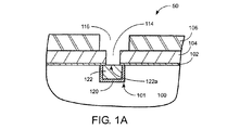
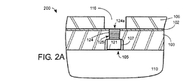
集積回路は、半導体基板上の個々の素子をつなぐためまたは集積回路に対して対外的に通信するために、導電性の配線を使用する。ビアおよびトレンチのための配線メタライゼーションは、アルミニウム合金および銅を含んでよい。素子形状が65nmノード技術およびサブ65nm技術へと縮小しつづけるにつれ、ステップカバレッジに優れた連続バリア/シード層を高アスペクト比の形状に沿って設けてボイドフリーの銅充填を提供することの困難さが増している。65nmノードまたはサブ65nmの技術において、極薄の共形バリアを求める動機は、ビアおよび線の抵抗に及ぼされるバリアの影響を小さくするためである。しかしながら、バリア層に対する銅の接着性が乏しいと、処理中にバリア層と銅との間に層間剥離が生じたり、あるいはエレクトロマイグレーションおよびストレス誘起ボイドの問題を引き起こす熱応力が発生したりする恐れがある。 Integrated circuits use conductive wiring to connect individual elements on a semiconductor substrate or to communicate externally to the integrated circuit. Wiring metallization for vias and trenches may include aluminum alloys and copper. As device geometries continue to shrink to 65nm node and sub-65nm technologies, it is difficult to provide a continuous barrier / seed layer with good step coverage along the high aspect ratio geometry to provide void-free copper filling Is increasing. The motivation for ultra-thin conformal barriers in 65 nm node or sub-65 nm technology is to reduce the barrier effect on via and line resistance. However, poor copper adhesion to the barrier layer can result in delamination between the barrier layer and copper during processing, or thermal stress that can cause electromigration and stress-induced voiding problems. is there.
以上から、エレクトロマイグレーション耐性に優れなおかつ銅配線におけるストレス誘起ボイドのリスクを低下させた方式で薄い共形バリア層と、銅層とを銅配線内に堆積させることを可能にするシステムおよびプロセスが必要とされていることがわかる。 From the above, there is a need for a system and process that is capable of depositing a thin conformal barrier layer and a copper layer in a copper interconnect in a manner that is excellent in electromigration resistance and reduces the risk of stress-induced voids in the copper interconnect. It turns out that it is said.
概して、実施形態は、エレクトロマイグレーション耐性に優れなおかつ銅配線に対するストレス誘起ボイドのリスクを低下させた方式で薄い共形のバリア層と、銅層とを銅配線内に堆積させることを可能にすることによってこの必要性を満たすものである。エレクトロマイグレーションおよびストレス誘起ボイドは、バリア層と銅層との間の接着性に影響され、これは、銅の堆積前にバリア層を金属リッチにすることおよび銅の堆積前にバリア層が曝露される酸素の量を制限することによって向上させることができる。あるいは、銅配線内に銅層を堆積させることを可能にするために、バリア層の上に機能化層を堆積させることができる。機能化層は、バリア層と銅層との間の接着性を向上させるために、バリア層および銅と強い結合を形成する。機能化層は、単に、バリア層の上に銅を堆積させることを可能にして銅層に置き換わることも可能である。本発明は、解決策、方法、プロセス、装置、またはシステムを含む多くの方式で実現可能であることを理解されるべきである。以下では、本発明のいくつかの実施形態が説明される。
本発明による方法は、銅配線のエレクトロマイグレーション耐性を向上させるために、統合システム内において前記銅配線の金属バリア層の上に機能化層を堆積させ、前記銅配線内における銅層の堆積を助けるための、基板の基板表面を調整する方法であって、
前記統合システム内において、前記銅配線を覆うために前記金属バリア層を堆積させ、前記金属バリア層を堆積させた後、前記基板が、金属バリア酸化物の形成を阻止するために制御環境内において搬送され処理される、ことと、
前記統合システム内において、前記金属バリア層の上に前記機能化層を堆積させることと、
前記金属バリア層の上に前記機能化層が堆積された後に、前記統合システム内において、前記銅配線内に前記銅層を堆積させることと、
を備え、
前記機能化層のために使用される材料は、少なくとも2つの端をともなう錯化基を含み、前記錯化基の一方の端は、前記金属バリア層との結合を形成し、前記錯化基のもう一方の端は、銅との結合を形成する、方法である。
本発明による統合システムは、銅配線のエレクトロマイグレーション耐性を向上させるために、制御環境内において基板を処理し、前記銅配線の金属バリア層の上に機能化層を堆積させることを可能にするための、統合システムであって、
実験室雰囲気搬送チャンバであって、前記実験室雰囲気搬送チャンバに結合された基板カセットから前記統合システム内へと前記基板を搬送可能である実験室雰囲気搬送チャンバと、
圧力が1トール未満の真空下において動作される真空搬送チャンバと、
前記金属バリア層を堆積させるための真空プロセスモジュールであって、前記真空搬送チャンバに結合され、圧力が1トール未満の真空下において動作される真空プロセスモジュールと、
不活性ガスの群より選択される不活性ガスで満たされた制御雰囲気搬送チャンバと、
前記金属バリア層の表面上に前記機能化層を堆積させるために使用される堆積プロセスモジュールであって、前記制御雰囲気搬送チャンバに結合された堆積プロセスモジュールと、
を備え、
前記機能化層のために使用される材料は、少なくとも2つの端をともなう錯化基を含み、前記錯化基の一方の端は、前記金属バリア層との結合を形成し、前記錯化基のもう一方の端は、銅との結合を形成する、統合システムである。
In general, embodiments enable a thin conformal barrier layer and a copper layer to be deposited within a copper interconnect in a manner that is electromigration resistant and reduces the risk of stress-induced voids on the copper interconnect. To meet this need. Electromigration and stress-induced voids are affected by the adhesion between the barrier layer and the copper layer, which makes the barrier layer metal rich prior to copper deposition and exposes the barrier layer prior to copper deposition. This can be improved by limiting the amount of oxygen that is produced. Alternatively, a functionalization layer can be deposited over the barrier layer to allow a copper layer to be deposited within the copper interconnect. The functionalized layer forms a strong bond with the barrier layer and copper in order to improve the adhesion between the barrier layer and the copper layer. The functionalized layer can simply replace the copper layer by allowing copper to be deposited over the barrier layer. It should be understood that the present invention can be implemented in many ways, including a solution, method, process, apparatus, or system. In the following, several embodiments of the invention will be described.
The method according to the present invention deposits a functionalized layer over the metal barrier layer of the copper interconnect in an integrated system to improve the electromigration resistance of the copper interconnect and assists in the deposition of the copper layer within the copper interconnect. A method for adjusting a substrate surface of a substrate,
Within the integrated system, after depositing the metal barrier layer to cover the copper interconnect and depositing the metal barrier layer, the substrate is in a controlled environment to prevent metal barrier oxide formation. Being transported and processed,
Depositing the functionalized layer on the metal barrier layer in the integrated system;
Depositing the copper layer in the copper interconnect in the integrated system after the functionalization layer is deposited on the metal barrier layer;
With
The material used for the functionalized layer comprises a complexing group with at least two ends, one end of the complexing group forming a bond with the metal barrier layer, and the complexing group The other end of the method is a method of forming a bond with copper.
The integrated system according to the present invention allows the substrate to be processed in a controlled environment and a functionalized layer deposited on the metal barrier layer of the copper interconnect to improve the electromigration resistance of the copper interconnect. An integrated system,
A laboratory atmosphere transfer chamber capable of transferring the substrate from a substrate cassette coupled to the laboratory atmosphere transfer chamber into the integrated system;
A vacuum transfer chamber that is operated under a vacuum at a pressure of less than 1 Torr;
A vacuum process module for depositing the metal barrier layer, wherein the vacuum process module is coupled to the vacuum transfer chamber and is operated under a vacuum at a pressure of less than 1 Torr;
A controlled atmosphere transfer chamber filled with an inert gas selected from the group of inert gases;
A deposition process module used to deposit the functionalized layer on the surface of the metal barrier layer, the deposition process module being coupled to the controlled atmosphere transfer chamber;
With
The material used for the functionalized layer comprises a complexing group with at least two ends, one end of the complexing group forming a bond with the metal barrier layer, and the complexing group The other end of is an integrated system that forms a bond with copper.
一実施形態では、銅配線のエレクトロマイグレーション耐性を向上させるために、統合システム内において銅配線の金属バリア層の上に機能化層を堆積させ、銅配線内における銅層の堆積を助けるための、基板の基板表面を調整する方法が提供される。方法は、統合システム内において、銅配線構造を覆うために金属バリア層を堆積させることを含み、金属バリア層を堆積させた後、基板は、金属バリア酸化物の形成を阻止するために制御環境内において搬送され処理される。方法は、また、統合システム内において、金属層の上に機能化層を堆積させることも含む。方法は、さらに、金属バリア層の上に機能化層が堆積された後に、統合システム内において、銅配線構造内に銅層を堆積させることを含む。 In one embodiment, to improve the electromigration resistance of the copper interconnect, a functionalization layer is deposited over the metal barrier layer of the copper interconnect in the integrated system to help deposit the copper layer in the copper interconnect. A method for conditioning a substrate surface of a substrate is provided. The method includes depositing a metal barrier layer to cover the copper interconnect structure within the integrated system, and after depositing the metal barrier layer, the substrate is in a controlled environment to prevent formation of the metal barrier oxide. It is conveyed and processed inside. The method also includes depositing a functionalization layer over the metal layer in the integrated system. The method further includes depositing a copper layer in the copper interconnect structure in the integrated system after the functionalization layer is deposited over the metal barrier layer.
別の一実施形態では、銅配線のエレクトロマイグレーション耐性を向上させるために、制御環境内において基板を処理し、銅配線の金属バリア層の上に機能化層を堆積させることを可能にするための、統合システムが提供される。システムは、実験室雰囲気搬送チャンバであって、該実験室雰囲気搬送チャンバに結合された基板カセットから統合システム内へと基板を搬送可能である実験室雰囲気搬送チャンバを含む。システムは、また、圧力が1トール未満の真空下において動作される真空搬送チャンバを含む。方法は、さらに、金属バリア層を堆積させるための真空プロセスモジュールであって、真空搬送チャンバに結合され、圧力が1トール未満の真空下において動作される真空プロセスモジュールを含む。また、方法は、不活性ガスの群より選択される不活性ガスで満たされた制御雰囲気搬送チャンバと、金属バリア層の表面上に機能化層を堆積させるために使用される堆積プロセスモジュールであって、制御雰囲気搬送チャンバに結合された堆積プロセスモジュールとを含む。 In another embodiment, to improve the electromigration resistance of a copper interconnect, the substrate is processed in a controlled environment to allow a functionalized layer to be deposited over the metal barrier layer of the copper interconnect. An integrated system is provided. The system includes a laboratory atmosphere transfer chamber that is capable of transferring a substrate from a substrate cassette coupled to the laboratory atmosphere transfer chamber into the integrated system. The system also includes a vacuum transfer chamber that is operated under a vacuum whose pressure is less than 1 Torr. The method further includes a vacuum process module for depositing a metal barrier layer, the vacuum process module coupled to a vacuum transfer chamber and operated under a vacuum at a pressure of less than 1 Torr. The method also includes a controlled atmosphere transfer chamber filled with an inert gas selected from the group of inert gases and a deposition process module used to deposit the functionalized layer on the surface of the metal barrier layer. And a deposition process module coupled to the controlled atmosphere transfer chamber.
本発明は、以下の適用例としても実現可能である。
[適用例1]
銅配線のエレクトロマイグレーション耐性を向上させるために、統合システム内において前記銅配線の金属バリア層の上に機能化層を堆積させ、前記銅配線内における銅層の堆積を助けるための、基板の基板表面を調整する方法であって、
前記統合システム内において、前記銅配線構造を覆うために前記金属バリア層を堆積させ、前記金属バリア層を堆積させた後、前記基板が、金属バリア酸化物の形成を阻止するために制御環境内において搬送され処理される、ことと、
前記統合システム内において、前記金属層の上に前記機能化層を堆積させることと、
前記金属バリア層の上に前記機能化層が堆積された後に、前記統合システム内において、前記銅配線構造内に前記銅層を堆積させることと、
を備える方法。
[適用例2]
適用例1に記載の方法であって、さらに、
前記金属バリア層を堆積させる前に、前記統合システム内において、前記銅配線に対して下位の金属の露出表面を洗浄し、前記下位の金属の前記露出表面の表面金属酸化物を除去することであって、前記下位の金属は、前記銅配線に電気的につながれた下位の配線の一部である、ことを備える方法。
[適用例3]
適用例1に記載の方法であって、さらに、
前記機能化層を堆積させる前に、前記統合システム内において、前記金属バリア層の表面を還元し、前記金属バリア層の前記表面を金属リッチにすることを備える方法。
[適用例4]
適用例1に記載の方法であって、
前記金属バリア層の材料は、窒化タンタル(TaN)、タンタル(Ta)、ルテニウム(Ru)、チタン(Ti)、タングステン(W)、ジルコン(Zr)、ハフニウム(Hf)、モリブデン(Mo)、ニオブ(Nb)、バナジウム(V)、ルテニウム(Ru)、およびクロム(Cr)、およびこれらの材料の異種混合からなる群より選択される、方法。
[適用例5]
適用例1に記載の方法であって、
前記機能化層のために使用される材料は、少なくとも2つの端をともなう錯化基を含み、前記錯化基の一方の端は、前記金属バリア層との結合を形成し、前記錯化基のもう一方の端は、銅との結合を形成する、方法。
[適用例6]
適用例4に記載の方法であって、
前記錯化基は、デカンチール、オクタデカンチオール、テトラフェニルポルフィン、二硫化ジフェニル、芳香族チオアセテート、ルテニウム(II)トリス(2,2,プライム−ビピリジン)チオール、チオフェノール、4,4プライム−ジチオジピリジン、二硫化ナフタレン、ビス(2−アントラキニル)二硫化物、3−メルカプトプロフィルトリメトキシシラン、γ−メタクリルオキシプロピルトリエトキシシラン、ペルフルオロオクタノキシルプロフィル−ジメチルシラン、アルキルトリクロロシラン、オクタデシルシロキサン、オクタノール、22−メルカプト−1−ドコサン酸、アルカンホスホン酸、オクタデカン酸、ジアミノドデカン、n−フェニルピロール、および2,5−ジチエニルピロールトライアッドからなる群より選択される、方法。
[適用例7]
適用例3に記載の方法であって、
前記金属バリア層の前記表面を還元することは、水素含有プラズマを使用して実施される、方法。
[適用例8]
適用例1に記載の方法であって、
前記銅配線はビアの上の金属線を含み、前記下位の配線は金属線を含む、方法。
[適用例9]
適用例1に記載の方法であって、
前記銅配線は金属線を含み、前記下位の配線はコンタクトを含む、方法。
[適用例10]
適用例2に記載の方法であって、
前記表面金属酸化物の前記露出表面を洗浄することは、Arスパッタリングプロセスまたはフッ素含有ガスを使用したプラズマプロセスを使用して達成される、方法。
[適用例11]
適用例10に記載の方法であって、
前記フッ素含有ガスは、NF 3 、CF 4 、または両者の組み合わせである、方法。
[適用例12]
適用例1に記載の方法であって、
前記金属バリア層を堆積させることは、さらに、
第1の金属バリア層を堆積させることと、
第2の金属バリア層を堆積させることと、
を含む、方法。
[適用例13]
適用例12に記載の方法であって、
前記第1の金属バリア層は、原子層成長(ALD)プロセスによって堆積され、前記第2の金属バリア層は、物理気相成長(PVD)プロセスによって堆積される、方法。
[適用例14]
適用例12に記載の方法であって、
前記第1の金属バリア層は、ALDプロセスによって堆積され、前記第2の金属バリア層は、ALDプロセスによって堆積される、方法。
[適用例15]
適用例1に記載の方法であって、さらに、
前記銅層を堆積させる前に、前記統合性ステム内において、前記機能化層の表面を洗浄することを備える方法。
[適用例16]
適用例1に記載の方法であって、
選択的に、前記薄い銅シード層は、無電解プロセスによって堆積される、方法。
[適用例17]
適用例1に記載の方法であって、
前記ギャップ充填銅層は、電解めっき(ECP)プロセスによって堆積される、方法。
[適用例18]
適用例1に記載の方法であって、
前記銅層は、前記機能化層に置き換わり、前記金属バリア層上に直接堆積する、方法。
[適用例19]
銅配線のエレクトロマイグレーション耐性を向上させるために、制御環境内において基板を処理し、前記銅配線の金属バリア層の上に機能化層を堆積させることを可能にするための、統合システムであって、
実験室雰囲気搬送チャンバであって、前記実験室雰囲気搬送チャンバに結合された基板カセットから前記統合システム内へと前記基板を搬送可能である実験室雰囲気搬送チャンバと、
圧力が1トール未満の真空下において動作される真空搬送チャンバと、
前記金属バリア層を堆積させるための真空プロセスモジュールであって、前記真空搬送チャンバに結合され、圧力が1トール未満の真空下において動作される真空プロセスモジュールと、
不活性ガスの群より選択される不活性ガスで満たされた制御雰囲気搬送チャンバと、
前記金属バリア層の表面上に前記機能化層を堆積させるために使用される堆積プロセスモジュールであって、前記制御雰囲気搬送チャンバに結合された堆積プロセスモジュールと、
を備える統合システム。
[適用例20]
適用例19に記載の統合システムであって、さらに、
前記金属バリア層の前記表面上に前記機能化層が堆積された後に前記銅配線内に薄い銅シード層を堆積させるために使用される無電解銅堆積プロセスモジュールであって、前記制御雰囲気搬送チャンバに結合された無電解銅堆積プロセスモジュールを備える統合システム。
[適用例21]
適用例19に記載の統合システムであって、さらに、
前記銅配線に電気的に接続された下位の配線の一部である下位の金属の金属酸化物の露出表面を洗浄するための真空プロセスモジュールであって、前記真空搬送チャンバに結合され、圧力が1トール未満の真空下において動作される真空プロセスモジュールを備える統合システム。
[適用例22]
適用例19に記載の統合システムであって、さらに、
前記金属バリア層の前記表面上に前記機能化層が堆積される前に前記金属バリアの前記表面上の金属酸化物または金属窒化物を還元して前記表面を金属リッチにするために使用される水素含有還元プロセスモジュールであって、前記真空搬送チャンバに結合され、圧力が1トール未満の真空下において動作される水素含有プロセスモジュールを備える統合システム。
[適用例23]
適用例20に記載の統合システムであって、
前記無電解銅堆積プロセスモジュールは、前記薄い銅シード層の上にギャップ充填銅層を堆積させるためにも使用される、統合システム。
[適用例24]
適用例20に記載の統合システムであって、さらに、
前記薄い銅シード層の上にギャップ充填銅層を堆積させるための無電解銅堆積プロセスモジュールを備える統合システム。
[適用例25]
適用例19に記載の統合システムであって、さらに、
前記金属バリア層の上に前記機能化層を堆積させた後に前記基板表面を洗浄するために使用される基板洗浄プロセスモジュールであって、前記制御雰囲気搬送モジュールに結合された基板洗浄プロセスモジュールを備える統合システム。
[適用例26]
適用例19に記載の統合システムであって、さらに、
前記真空搬送チャンバおよび前記制御雰囲気搬送チャンバに結合され、前記真空搬送チャンバと前記制御雰囲気搬送チャンバとの間における前記基板の搬送を支援する第1のロードロックと、
前記真空搬送チャンバおよび前記実験室雰囲気搬送チャンバに結合され、前記真空搬送チャンバと前記実験室雰囲気搬送チャンバとの間における前記基板の搬送を支援する第2のロードロックと、
を備え、
前記第1のロードロックは、圧力が1トール未満の真空下において動作されるように、又は、不活性ガスの群より選択される不活性ガスで満たされるように構成されており、
前記第2のロードロックは、圧力が1トール未満の真空下において動作されるように、又は、実験室雰囲気において動作されるように、又は、不活性ガスの群より選択される不活性ガスで満たされるように構成されている、
統合システム。
[適用例27]
適用例19に記載の統合システムであって、
前記真空搬送チャンバおよび前記真空搬送チャンバに結合された前記少なくとも1つの真空プロセスモジュールは、前記基板の酸素への曝露を制御するために、1トール未満の圧力において動作される、統合システム。
[適用例28]
適用例19に記載の統合システムであって、
前記制御雰囲気搬送チャンバおよび前記制御雰囲気搬送チャンバに結合された少なくとも1つのプロセスモジュールは、前記基板の酸素への曝露を制御するために、不活性ガスの群より選択される1つまたは2つ以上の不活性ガスで満たされる、統合システム。
[適用例29]
適用例19に記載の統合システムであって、
基板は、前記基板が酸素に曝露される時間を制限するために、前記統合システム内において搬送され処理される、統合システム。
[適用例30]
適用例29に記載の方法であって、
前記基板表面の酸素への曝露を制限することは、前記機能化層を前記金属バリア層の前記表面上に堆積させることを可能にする、方法。
[適用例31]
適用例19に記載の統合システムであって、
前記制御雰囲気搬送モジュールに結合された前記少なくとも1つのプロセスモジュールは、前記基板のドライイン、ドライアウト処理を可能にし、前記基板は、乾燥した状態で前記少なくとも1つのプロセスモジュールに出入りする、統合システム。
本発明の原理を例示した添付の図面に関連させた以下の詳細な説明から、本発明のその他の態様および利点が明らかになる。
The present invention can also be realized as the following application examples.
[Application Example 1]
A substrate substrate for depositing a functionalization layer over the metal barrier layer of the copper interconnect in an integrated system to improve the electromigration resistance of the copper interconnect and assisting the deposition of the copper layer in the copper interconnect A method of adjusting the surface,
Within the integrated system, after depositing the metal barrier layer to cover the copper interconnect structure and depositing the metal barrier layer, the substrate is in a controlled environment to prevent metal barrier oxide formation. Being transported and processed in
Depositing the functionalized layer on the metal layer in the integrated system;
Depositing the copper layer in the copper interconnect structure in the integrated system after the functionalization layer is deposited on the metal barrier layer;
A method comprising:
[Application Example 2]
The method according to application example 1, further comprising:
Before depositing the metal barrier layer, in the integrated system, the exposed surface of the lower metal with respect to the copper wiring is cleaned and the surface metal oxide on the exposed surface of the lower metal is removed. And wherein the lower metal is part of a lower wiring electrically connected to the copper wiring.
[Application Example 3]
The method according to application example 1, further comprising:
Before depositing the functionalized layer, the method comprises reducing the surface of the metal barrier layer and making the surface of the metal barrier layer metal rich in the integrated system.
[Application Example 4]
A method described in application example 1,
The material of the metal barrier layer is tantalum nitride (TaN), tantalum (Ta), ruthenium (Ru), titanium (Ti), tungsten (W), zircon (Zr), hafnium (Hf), molybdenum (Mo), niobium. A method selected from the group consisting of (Nb), vanadium (V), ruthenium (Ru), and chromium (Cr), and heterogeneous mixtures of these materials.
[Application Example 5]
A method described in application example 1,
The material used for the functionalized layer comprises a complexing group with at least two ends, one end of the complexing group forming a bond with the metal barrier layer, and the complexing group The other end of the method forms a bond with copper.
[Application Example 6]
A method described in application example 4,
The complexing groups are decantyl, octadecanethiol, tetraphenylporphine, diphenyl disulfide, aromatic thioacetate, ruthenium (II) tris (2,2, prime-bipyridine) thiol, thiophenol, 4,4 prime-dithiodi. Pyridine, naphthalene disulfide, bis (2-anthraquinyl) disulfide, 3-mercaptoprofile trimethoxysilane, γ-methacryloxypropyltriethoxysilane, perfluorooctanoyl profile-dimethylsilane, alkyltrichlorosilane, octadecylsiloxane, octanol Selected from the group consisting of 22-mercapto-1-docosanoic acid, alkanephosphonic acid, octadecanoic acid, diaminododecane, n-phenylpyrrole, and 2,5-dithienylpyrrole triad The method.
[Application Example 7]
A method described in application example 3,
The method wherein reducing the surface of the metal barrier layer is performed using a hydrogen-containing plasma.
[Application Example 8]
A method described in application example 1,
The method wherein the copper interconnect includes a metal line over a via and the subordinate interconnect includes a metal line.
[Application Example 9]
A method described in application example 1,
The copper wiring includes a metal wire, and the lower wiring includes a contact.
[Application Example 10]
A method described in application example 2,
Cleaning the exposed surface of the surface metal oxide is accomplished using an Ar sputtering process or a plasma process using a fluorine-containing gas.
[Application Example 11]
The method according to application example 10,
The method, wherein the fluorine-containing gas is NF 3 , CF 4 , or a combination of both.
[Application Example 12]
A method described in application example 1,
Depositing the metal barrier layer further comprises:
Depositing a first metal barrier layer;
Depositing a second metal barrier layer;
Including a method.
[Application Example 13]
The method according to application example 12,
The method wherein the first metal barrier layer is deposited by an atomic layer deposition (ALD) process and the second metal barrier layer is deposited by a physical vapor deposition (PVD) process.
[Application Example 14]
The method according to application example 12,
The method wherein the first metal barrier layer is deposited by an ALD process and the second metal barrier layer is deposited by an ALD process.
[Application Example 15]
The method according to application example 1, further comprising:
Cleaning the surface of the functionalized layer in the integration stem prior to depositing the copper layer.
[Application Example 16]
A method described in application example 1,
Optionally, the thin copper seed layer is deposited by an electroless process.
[Application Example 17]
A method described in application example 1,
The method, wherein the gap-fill copper layer is deposited by an electroplating (ECP) process.
[Application Example 18]
A method described in application example 1,
The copper layer replaces the functionalized layer and is deposited directly on the metal barrier layer.
[Application Example 19]
An integrated system for allowing a substrate to be processed in a controlled environment and to deposit a functionalized layer on top of the copper barrier metal barrier layer to improve electromigration resistance of the copper interconnect. ,
A laboratory atmosphere transfer chamber capable of transferring the substrate from a substrate cassette coupled to the laboratory atmosphere transfer chamber into the integrated system;
A vacuum transfer chamber that is operated under a vacuum at a pressure of less than 1 Torr;
A vacuum process module for depositing the metal barrier layer, wherein the vacuum process module is coupled to the vacuum transfer chamber and is operated under a vacuum at a pressure of less than 1 Torr;
A controlled atmosphere transfer chamber filled with an inert gas selected from the group of inert gases;
A deposition process module used to deposit the functionalized layer on the surface of the metal barrier layer, the deposition process module being coupled to the controlled atmosphere transfer chamber;
Integrated system with.
[Application Example 20]
The integrated system according to Application Example 19,
An electroless copper deposition process module used to deposit a thin copper seed layer in the copper interconnect after the functionalization layer is deposited on the surface of the metal barrier layer, the controlled atmosphere transfer chamber An integrated system comprising an electroless copper deposition process module coupled to the.
[Application Example 21]
The integrated system according to Application Example 19,
A vacuum process module for cleaning an exposed surface of a metal oxide of a lower metal that is part of a lower wiring electrically connected to the copper wiring, the vacuum process module being coupled to the vacuum transfer chamber and having a pressure An integrated system comprising a vacuum process module operated under a vacuum of less than 1 Torr.
[Application Example 22]
The integrated system according to Application Example 19,
Used to reduce the metal oxide or metal nitride on the surface of the metal barrier to make the surface metal rich before the functionalized layer is deposited on the surface of the metal barrier layer An integrated system comprising a hydrogen-containing reduction process module, wherein the hydrogen-containing reduction process module is coupled to the vacuum transfer chamber and is operated under vacuum at a pressure of less than 1 Torr.
[Application Example 23]
An integrated system described in Application Example 20,
The integrated system wherein the electroless copper deposition process module is also used to deposit a gap-fill copper layer over the thin copper seed layer.
[Application Example 24]
An integrated system according to Application Example 20,
An integrated system comprising an electroless copper deposition process module for depositing a gap-fill copper layer on the thin copper seed layer.
[Application Example 25]
The integrated system according to Application Example 19,
A substrate cleaning process module used to clean the substrate surface after depositing the functionalized layer on the metal barrier layer, the substrate cleaning process module coupled to the controlled atmosphere transfer module Integrated system.
[Application Example 26]
The integrated system according to Application Example 19,
A first load lock coupled to the vacuum transfer chamber and the controlled atmosphere transfer chamber and supporting transfer of the substrate between the vacuum transfer chamber and the controlled atmosphere transfer chamber;
A second load lock coupled to the vacuum transfer chamber and the laboratory atmosphere transfer chamber and supporting transfer of the substrate between the vacuum transfer chamber and the laboratory atmosphere transfer chamber;
With
The first load lock is configured to be operated under a vacuum at a pressure of less than 1 Torr, or to be filled with an inert gas selected from the group of inert gases;
The second load lock is an inert gas selected to operate under a vacuum with a pressure less than 1 Torr, or to operate in a laboratory atmosphere, or selected from the group of inert gases. Configured to be satisfied,
Integrated system.
[Application Example 27]
An integrated system described in Application Example 19,
The integrated system, wherein the vacuum transfer chamber and the at least one vacuum process module coupled to the vacuum transfer chamber are operated at a pressure of less than 1 Torr to control exposure of the substrate to oxygen.
[Application Example 28]
An integrated system described in Application Example 19,
The control atmosphere transfer chamber and at least one process module coupled to the control atmosphere transfer chamber are one or more selected from the group of inert gases to control exposure of the substrate to oxygen Integrated system filled with inert gas.
[Application Example 29]
An integrated system described in Application Example 19,
An integrated system wherein the substrate is transported and processed within the integrated system to limit the time that the substrate is exposed to oxygen.
[Application Example 30]
The method according to application example 29,
Limiting exposure of the substrate surface to oxygen allows the functionalized layer to be deposited on the surface of the metal barrier layer.
[Application Example 31]
An integrated system described in Application Example 19,
The integrated system, wherein the at least one process module coupled to the controlled atmosphere transfer module enables dry-in and dry-out processing of the substrate, and the substrate enters and exits the at least one process module in a dry state. .
Other aspects and advantages of the invention will become apparent from the following detailed description, taken in conjunction with the accompanying drawings, illustrating by way of example the principles of the invention.
本発明は、添付の図面に関連させた以下の詳細な説明によって、容易に理解することができる。ここで、類似の参照符号は、類似の構成要素を示すものとする。 The present invention can be readily understood by the following detailed description in conjunction with the accompanying drawings. Here, similar reference numerals indicate similar components.
界面の接着性を向上させなおかつ金属配線の抵抗性を下げるために還元によって界面金属酸化物を除去するまたは接着促進層を追加する金属統合技術について、いくつかの代表的な実施形態が提供される。本発明は、プロセス、方法、装置、またはシステムを含む多くの方式で実現可能であることを理解されるべきである。発明力のある本発明のいくつかの実施形態が、以下で説明される。当業者ならば明らかなように、本発明は、本明細書において特定された一部または全部の詳細をともなわずとも実施可能である。 Several exemplary embodiments are provided for metal integration techniques that remove interfacial metal oxides or add adhesion promoting layers by reduction to improve interfacial adhesion and reduce metal interconnect resistance. . It should be understood that the present invention can be implemented in many ways, including as a process, method, apparatus, or system. Several inventive embodiments of the invention are described below. It will be apparent to those skilled in the art that the present invention may be practiced without some or all of the details specified herein.
図1Aは、デュアルダマシンプロセス手順を使用してパターン形成された後の配線構造の代表的な断面を示している。配線構造は、基板50上にあり、事前の作成によってメタライゼーション線101を内部に形成された誘電体層100を有している。メタライゼーション線は、一般に、誘電体100内にトレンチをエッチングし次いでそのトレンチに銅などの導電材料を充填することによって作成される。
FIG. 1A shows a representative cross section of a wiring structure after it has been patterned using a dual damascene process procedure. The wiring structure has a
トレンチ内には、銅材料122が誘電体100内に拡散するのを阻止するために使用されるバリア層120がある。バリア層120は、物理気相成長(PVD)窒化タンタル(TaN)、PVDタンタル(Ta)、原子層成長(ALD)TaN、またはこれらの膜の組み合わせで作成することができる。その他のバリア層材料もまた、使用することができる。バリア層102は、上位の誘電体材料104,106を通ってバリア層102へとビアホール114がエッチングされる際に、銅材料122が時期尚早に酸化されないように保護するために、平坦化された銅材料122の上に堆積される。バリア層102は、選択性のエッチングストップとして機能するようにも構成される。代表的なバリア層102材料は、窒化シリコン(SiN)または炭化シリコン(SiC)を含む。
Within the trench is a
バリア層102の上に、ビア誘電体層104が堆積される。ビア誘電体層104は、有機ケイ酸塩ガラス(OSG、炭素ドープ酸化シリコン)または好ましくは低誘電率のその他のタイプの誘電体材料で作成することができる。代表的な二酸化シリコンとしては、PECVD非ドープTEOS二酸化シリコン、PECVDフッ素化シリカガラス(FSG)、HDP FSG、OSG、ポーラスOSGなどを挙げることができる。カリフォルニア州サンタクララのApplied MaterialsによるBlack Diamond (I)およびBlack Diamond (II)、サンノゼのNovellus SystemsによるCoral、アリゾナ州フェニックスのASM America Inc.によるAuroraを含む市販の誘電体材料もまた、使用することができる。ビア誘電体層104の上は、トレンチ誘電体層106である。トレンチ誘電体層106は、炭素ドープ酸化物(C酸化物)などの低誘電率(low−k)誘電体材料であってよい。低誘電率誘電体材料の誘電率は、約3.0またはそれ未満であってよい。一実施形態では、ビア誘電体層およびトレンチ誘電体層は、ともに同じ材料で作成され、同時に堆積されて連続膜を形成する。トレンチ誘電体層106が堆積された後、この(これらの)構造を保持する基板50は、既知の技術によって、ビアホール114およびトレンチ116を形成するためのパターン形成プロセスおよびエッチングプロセスを経る。
A via
図1Bは、ビアホール114およびトレンチ116の形成後に、ビアホール114およびトレンチ116の被覆および充填のためにバリア層130と銅層132とが堆積されることを示している。バリア層130は、窒化タンタル(TaN)、タンタル(Ta)、ルテニウム(Ru)、またはこれらの材料の異種混合で作成することができる。これらは、一般に考えられる材料であるが、その他のバリア層材料もまた、使用することができる。バリア層材料は、とりわけ、チタン(Ti)、タングステン(W)、ジルコン(Zr)、ハフニウム(Hf)、モリブデン(Mo)、ニオブ(Nb)、バナジウム(V)、ルテニウム(Ru)、およびクロム(Cr)を非限定例として含むその他の耐熱性金属化合物であってもよい。
FIG. 1B shows that after formation of via
図1Cに示されるように、次いで、ビアホール114およびトレンチ116を充填するために、銅膜132が堆積される。一実施形態では、銅膜132は、その下に薄い銅シード層131を含む。一実施形態では、薄い銅シード層の厚さは、約5オングストロームから約300オングストロームまでの間である。
As shown in FIG. 1C, a
Ta、TaN、またはRuなどのバリア層は、長期間にわたって空気に曝露されると、TaxOy(酸化タンタル)、TaOxNy(窒酸化タンタル)、またはRuO2(酸化ルテニウム)を形成する恐れがある。基板上への金属層の無電解堆積は、基板の表面特性および組成に大きく依存する。Ta、TaN、またはRuの表面上への銅の無電解めっきは、電解めっきに先立つシード層の形成およびリソグラフィ的に画定されたパターン内へのCu線の選択的堆積の双方にとっての関心事である。懸念の1つは、酸素(O2)の存在下において形成される原子的に薄い自然金属酸化物の層によって、無電解堆積プロセスが抑制されることである。 Barrier layers such as Ta, TaN, or Ru form Ta x O y (tantalum oxide), TaO x N y (tantalum oxynitride), or RuO 2 (ruthenium oxide) when exposed to air for extended periods of time. There is a fear. Electroless deposition of a metal layer on a substrate is highly dependent on the surface properties and composition of the substrate. Electroless plating of copper on Ta, TaN, or Ru surfaces is a concern for both the formation of a seed layer prior to electroplating and the selective deposition of Cu lines in a lithographically defined pattern. is there. One concern is that the electroless deposition process is suppressed by an atomically thin layer of native metal oxide formed in the presence of oxygen (O 2 ).
また、銅膜は、酸化タンタルや、窒酸化タンタル、酸化ルテニウムなどのバリア酸化物層には接着せず、Ta膜や、Ru膜、TaリッチTaN膜などの純粋なバリア金属膜またはバリア層リッチ膜には接着する。Taおよび/またはTaNのバリア層は、例として使用されているに過ぎない。説明および概念は、Ruの薄い層を被せられたTaまたはTaNなどのその他のタイプのバリア金属にも当てはまる。上述のように、乏しい接着性は、EM耐性に悪影響を及ぼす恐れがある。また、バリア層表面上への酸化タンタルまたは窒酸化タンタルの形成は、バリア層の抵抗性を増大させる恐れがある。これらの問題ゆえに、統合システムを使用してバリア/銅界面を調整し、バリア層と銅との間に優れた接着性を保証することおよびバリア層の抵抗性を小さく保証することが望まれる。 In addition, the copper film does not adhere to a barrier oxide layer such as tantalum oxide, tantalum nitride oxide, or ruthenium oxide, but is pure barrier metal film or barrier layer rich such as Ta film, Ru film, or Ta-rich TaN film. Adhere to the membrane. Ta and / or TaN barrier layers are only used as examples. The description and concept apply to other types of barrier metals such as Ta or TaN coated with a thin layer of Ru. As mentioned above, poor adhesion can adversely affect EM resistance. Also, the formation of tantalum oxide or tantalum oxynitride on the barrier layer surface may increase the resistance of the barrier layer. Because of these problems, it is desirable to use an integrated system to tune the barrier / copper interface to ensure excellent adhesion between the barrier layer and copper and to ensure low barrier layer resistance.
図1Bは、バリア層130が、ALDまたはPVDのいずれかによって堆積された一層であることを示している。あるいは、バリア層130は、図1Dに示されるように、ALDプロセスによってTaNなどの第1のバリア層130Iを堆積させ、次いでPVDによってTaなどの第2のバリア層130IIを堆積させることによって、堆積させることができる。
FIG. 1B shows that the
デュアルダマシン配線構造に加えて、銅配線は、コンタクトの上の金属線(すなわちM1線)にも適用することができる。図2Aは、誘電体エッチングによってパターン形成され、フォトレジストを除去された後における、金属線構造の代表的な断面を示している。金属線構造は、基板200上にあり、事前の作成によってゲート酸化物121、スペーサ107、およびコンタクト125をともなうゲート構造105を内部に形成されたシリコン層110を有している。コンタクト125は、一般に、酸化物103内にコンタクトホールをエッチングし次いでそのコンタクトホールにタングステンなどの導電性材料を充填することによって作成される。代替の材料は、銅、アルミニウム、またはその他の導電性材料を含んでよい。バリア層102は、選択的なトレンチエッチングストップとして機能するように構成される。バリア層102は、窒化シリコン(SiN)または炭化シリコン(SiC)などの材料で作成することができる。
In addition to the dual damascene wiring structure, copper wiring can also be applied to metal lines (ie, M1 lines) on the contacts. FIG. 2A shows a representative cross section of a metal line structure after it has been patterned by dielectric etching and the photoresist has been removed. The metal line structure is on a
バリア層102の上に、金属線誘電体層106が堆積される。106の堆積に使用することができる誘電体材料は、上述されている。誘電体層106の堆積後、基板は、金属トレンチ116を形成するために、パターン形成されエッチングされる。図2Bは、金属トレンチ116の形成後、金属トレンチ116に裏打ちするために金属バリア層130が堆積されることを示している。図2Cは、バリア層130の堆積後、バリア層130の上に銅層132が堆積されることを示している。デュアルダマシン配線構造の場合と同様に、バリア層130は、窒化タンタル(TaN)、タンタル(Ta)、Ru、またはこれらの膜の組み合わせで作成することができる。次いで、金属トレンチ116に充填するために、銅膜132が堆積される。
A metal
デュアルダマシン構造について上述されたように、Ta、TaN、またはRuなどのバリア層は、長期間にわたって空気に曝露されると、TaxOy(酸化タンタル)、TaOxNy(窒酸化タンタル)、またはRuO2(酸化ルテニウム)を形成する恐れがある。基板上への金属層の無電解堆積は、基板の表面特性および組成に大きく依存する。Ta、TaN、またはRuの表面上への銅の無電解めっきは、電解めっきに先立つシード層の形成およびリソグラフィ的に画定されたパターン内へのCu線の選択的堆積の双方にとっての関心事である。上述のように、懸念は、酸素(O2)の存在下において形成される原子的に薄い自然金属酸化物の層によって、無電解堆積プロセスが抑制されることである。また、銅膜は、酸化タンタルや、窒酸化タンタル、酸化ルテニウムなどのバリア酸化物層には接着せず、Ta膜や、Ru膜、TaリッチTaN膜などの純粋なバリア金属膜またはバリア層リッチ膜には接着する。上述のように、乏しい接着性は、EM耐性に悪影響を及ぼす恐れがある。バリア層表面上への酸化タンタルまたは窒酸化タンタルの形成は、バリア層の抵抗性を増大させる恐れもある。これらの問題ゆえに、統合システムを使用してバリア/銅界面を調整し、バリア層と銅との間に優れた接着性を保証することおよびバリア層の抵抗性を小さく保証することが望まれる。 As described above for the dual damascene structure, barrier layers such as Ta, TaN, or Ru, when exposed to air for extended periods of time, Ta x O y (tantalum oxide), TaO x N y (tantalum oxynitride) Or RuO 2 (ruthenium oxide). Electroless deposition of a metal layer on a substrate is highly dependent on the surface properties and composition of the substrate. Electroless plating of copper on Ta, TaN, or Ru surfaces is a concern for both the formation of a seed layer prior to electroplating and the selective deposition of Cu lines in a lithographically defined pattern. is there. As mentioned above, the concern is that the electroless deposition process is suppressed by the atomically thin native metal oxide layer formed in the presence of oxygen (O 2 ). In addition, the copper film does not adhere to a barrier oxide layer such as tantalum oxide, tantalum nitride oxide, or ruthenium oxide, but is pure barrier metal film or barrier layer rich such as Ta film, Ru film, or Ta-rich TaN film. Adhere to the membrane. As mentioned above, poor adhesion can adversely affect EM resistance. Formation of tantalum oxide or tantalum oxynitride on the surface of the barrier layer can also increase the resistance of the barrier layer. Because of these problems, it is desirable to use an integrated system to tune the barrier / copper interface to ensure excellent adhesion between the barrier layer and copper and to ensure low barrier layer resistance.
図3Aは、(図2Aの)トレンチ116などのトレンチの形成後、無電解銅堆積のためにバリア(またはライナ)層表面を調整するプロセスフロー300の一実施形態を示している。図2A〜2Cに示されるような、コンタクトプラグの上への金属トレンチ配線の形成は、一例として使用されているに過ぎない。発明の概念は、図1A〜1Dに示されるような金属トレンチの上へのデュアルダマシン配線構造の形成またはその他の適用可能な配線構造の形成に使用することもできる。しかしながら、バリア(またはライナ)層は、ALDまたはPVDの堆積リアクタなどの非統合型の堆積システム内において、個別に調整されてもよいことに留意せよ。この場合、薄い銅シード層を堆積させるための表面調整は、金属プラグの前洗浄のステップおよびバリア堆積プロセスのステップを含まないと考えられる。ステップ301では、自然金属酸化物を除去するために、コンタクトプラグの上面124aが洗浄される。金属酸化物は、Arスパッタリングプロセス、NF3、CF4、もしくは両者の組み合わせなどのフッ素含有ガスを使用したプラズマプロセス、湿式化学的エッチングプロセス、または例えば水素含有プラズマを使用した還元プロセスによって除去することができる。金属酸化物は、1ステップまたは2ステップの湿式化学的プロセス手順の湿式化学的除去プロセスによって除去することができる。湿式化学的除去プロセスは、日本の関東化学株式会社によって提供されているDeerCleanなどの有機酸、デラウェア州ウィルミントンのDuPontによって提供されているESC 5800などの半水性溶媒、塩化テトラメチルアンモニウム(TMAH)などの有機塩基、エチレンジアミンやジエチレントリアミンなどの錯化アミン、またはコネティカット州ウェストヘーブンのEnthone, Inc.によって提供されているELD洗浄およびCap Clean 61などの特許化学剤を使用することができる。また、とりわけ酸化銅などの金属酸化物は、クエン酸などの弱い有機酸を使用して除去することができる、あるいはその他の有機酸または無機酸を使用することができる。また、硫黄−過酸化物混合などの、非常に薄い(すなわち<0.1%の)過酸化物含有酸もまた、使用することができる。
FIG. 3A illustrates one embodiment of a
ステップ303では、バリア層が堆積される。金属線およびビアの限界寸法の縮小ゆえに、バリア層は、技術ノード次第では、原子層成長(ALD)によって堆積させることができる。バリア層130の厚さは、約20オングストロームから約200オングストロームまでの間である。上述のように、バリア層の酸素への曝露を防ぐことは、銅とバリア層との間の接着性に優れた方式でバリア層上に確実に無電解銅を堆積させるのに重要である。バリア層が堆積されると、基板は、酸素への曝露を制限するために、制御雰囲気環境内において搬送または処理されることが望ましい。一実施形態において、バリア層は、後続の銅シード堆積ステップのための触媒表面を提供するために、ステップ305において、水素プラズマ処理を施され、Ta、TaN、またはRuなどのバリア層上に金属リッチ表面を形成される。還元プラズマは、水素またはアンモニアなどのガスを含むことができる。還元プラズマは、ArまたはHeなどの不活性ガスを含むことができる。もし、バリア層堆積後のバリア表面が金属リッチであるならば、ステップ305は、随意のステップである。例えば、もし、堆積されたバリア層がタンタルまたはルテニウムの層であるならば、表面還元ステップは、不要である。他方で、もし、堆積されたバリア層がTaNなどのバリア窒化物層であるならば、あるいは、もし、バリア層が酸素に曝露されるならば、水素プラズマによる処理(または還元)が必要とされるであろう。このステップが必要であるか否かは、表面がどの程度金属リッチであるかに依存する。
In
その後、ステップ307において、バリア表面上に共形の銅シードが堆積され、そして、ステップ308において、厚い銅をギャップ充填(またはバルク充填)するプロセスが続く。一実施形態では、共形の銅シード層は、無電解プロセスによって堆積させることができる。厚い銅をバルク充填するプロセスは、無電解堆積(ELD)プロセスまたは電解めっき(ECP)プロセスであってよい。無電解銅堆積およびECPは、周知の湿式プロセスである。制御された処理&搬送環境をともなうシステムに湿式プロセスを統合させるには、リアクタをリンス/ドライヤに統合し、ドライイン、ドライアウトのプロセス能力を可能にする必要がある。また、システムは、基板の酸素への曝露を確実に最小限に抑えられるように、不活性ガスで満たされる必要がある。無電解堆積プロセスは、パドルめっきなどの数々の方式で行うことができる。パドルめっきでは、流体が基板上に供給され、静止した状態で反応を進められる。その後、反応剤は、除去され廃棄される、または再生される。近年では、ドライイン、ドライアウトの無電解銅プロセスが開発されている。プロセスは、プロキシミティプロセスヘッドを使用して、無電解プロセス液を基板表面の限定領域と接触する範囲内に収める。プロキシミティプロセスヘッドの下方にない基板表面は、乾燥している。さらに、プロセスにおいて使用される全ての流体は、市販の脱ガスシステムによって脱ガスされている、すなわち溶存酸素を除去されている。
Thereafter, in
ステップ307,308における銅堆積の後、基板は、ステップ309における随意の基板洗浄を経ることができる。銅堆積の後の洗浄は、ペンシルバニア州アレンタウンのAir Products and Chemical, Inc.によって供給されているCP72Bを含有した溶液などの化学溶液によるブラシスクラブ洗浄を使用して達成することができる。LamのC3(商標)またはAMC(商標、高度な機械的洗浄)による洗浄技術などのその他の基板表面洗浄プロセスもまた、使用することができる。
After copper deposition in
図3Bは、バリア表面調整後の重要なステップにおいて基板表面の酸素への曝露を最小限に抑えることができる統合システム350の一実施形態の概略図を示している。また、これは統合システムであるので、基板は、1つのプロセスステーションから直ちに次のプロセスステーションへと搬送され、これは、清浄なバリア表面が低レベルの酸素に曝露される時間を制限する。統合システム350は、図3Aのフロー300のプロセス手順全体を通して基板処理に使用することができる。
FIG. 3B shows a schematic diagram of an embodiment of an
上述のように、銅の無電解堆積のための表面調整プロセスおよび随意のコバルト合金堆積後プロセスは、乾式プロセスと湿式プロセスとの混合をともなう。湿式プロセスは、一般に、ほぼ大気圧で動作され、乾式プラズマプロセスは、1トール未満で動作される。また、バリア層の堆積後、基板が曝露される酸素は可能な限り少量であることが望ましく、これは、制御環境内における搬送および処理によって実現することができる。したがって、統合システムは、乾式プロセスと湿式プロセスとの混合を取り扱える必要がある。制御された処理&搬送環境をともなうシステムに湿式プロセスを統合するには、リアクタをリンス/ドライヤに統合し、ドライイン、ドライアウトのプロセス能力を可能にする必要がある。また、システムは、基板の酸素への曝露を確実に最小限に抑えられるように、不活性ガスで満たされる必要がある。統合システム350は、3つの基板搬送モジュール360,370,380を有する。搬送モジュール360,370,380は、基板355を1つのプロセス区域から別のプロセス区域へと移動させるためのロボットを装備している。プロセス区域は、基板カセット、リアクタ、またはロードロックであってよい。基板搬送モジュール360は、実験室雰囲気下で動作される。モジュール360は、基板355を統合システムに持ち込むためまたは基板をカセット361の1つに戻すために、基板ローダ(または基板カセット)361と連携して機能する。
As described above, the surface conditioning process for the electroless deposition of copper and the optional post-deposition cobalt alloy process involve a mixture of dry and wet processes. Wet processes are generally operated at approximately atmospheric pressure, and dry plasma processes are operated at less than 1 Torr. Also, after deposition of the barrier layer, it is desirable that the substrate is exposed to as little oxygen as possible, which can be achieved by transport and processing in a controlled environment. Thus, the integrated system needs to be able to handle a mix of dry and wet processes. To integrate a wet process into a system with a controlled processing and transport environment, the reactor must be integrated into a rinse / dryer to enable dry-in and dry-out process capabilities. The system also needs to be filled with an inert gas to ensure that exposure of the substrate to oxygen is minimized. The
プロセスフロー300において上述されたように、基板355は、バリア層および銅層を堆積させるために統合システム350に持ち込まれる。プロセスフロー300のステップ301において説明されたように、自然酸化タングステンを除去するために、コンタクト125のタングステン上面124aがエッチングされる。酸化タングステンが除去されると、露出された図2Aのタングステン表面124aは、酸素に曝露されないように保護される必要がある。もし、除去プロセスがArスパッタリングプロセスであるならば、リアクタ371は、真空搬送モジュール370に結合される。もし、湿式の化学的エッチングが選択されるならば、リアクタは、タングステン表面の酸素への曝露を制限するために、実験室雰囲気搬送モジュール360ではなく、制御雰囲気搬送モジュール380に結合されることが望ましい。
As described above in
その後、基板は、図3Aのステップ303において説明されたように、Ta、TaN、Ru、またはこれらの膜の組み合わせなどの金属バリア層を堆積される。図2Bのバリア層130は、ALDプロセスまたはPVDプロセスによって堆積させることができる。一実施形態では、ALDプロセスは、1トール未満で動作される。ALDリアクタ373は、真空搬送モジュール370に結合される。別の一実施形態では、堆積プロセスは、金属バリアを形成するために、超臨界CO2および有機金属前駆体を使用する高圧プロセスである。さらに別の一実施形態では、堆積プロセスは、1トール未満の圧力で動作される物理気相成長(PVD)プロセスである。
The substrate is then deposited with a metal barrier layer, such as Ta, TaN, Ru, or a combination of these films, as described in
基板は、例えば、図3Aのステップ305において説明されたように、水素含有プラズマを使用した随意の還元(水素プラズマ処理)プロセスを経ることができる。水素還元リアクタ374は、真空搬送モジュール370に結合することができる。この段階で、基板は、無電解銅堆積の用意が整う。無電解銅めっきは、共形のシード層を堆積させるために、無電解銅めっきリアクタ381内において実施することができる。シード層の堆積に続いて、共形シード層の堆積に使用されたのと同じ無電解銅堆積リアクタ381内において、ただし、バルク充填を実現するための異なる化学物質を使用して、銅のバルク充填を実施することができる。あるいは、銅のバルク充填は、別個のECPリアクタ381’内において実施することができる。
The substrate can undergo an optional reduction (hydrogen plasma treatment) process using a hydrogen-containing plasma, for example, as described in
統合システム350を後にする前に、基板は、先の銅堆積プロセスからの残留物を洗浄することができる表面洗浄プロセスを随意に経ることができる。例えば、基板洗浄プロセスは、ブラシ洗浄プロセスであってよい。基板洗浄リアクタ383は、制御雰囲気搬送モジュール380に統合することができる。あるいは、基板洗浄リアクタ383は、実験室雰囲気搬送モジュール360に統合することもできる。あるいは、図2Bのバリア層130は、基板200が表面処理および銅堆積のためにシステムに持ち込まれる前に、プロセスチャンバ内において堆積させることができる。上述のように、図3Aにおいて説明されたプロセスフロー300および図3Bにおいて説明されたシステム350は、図1A〜1Dに示されるようなデュアルダマシン構造またはその他の適用可能な配線構造のためにバリア層および銅を堆積させるために使用することもできる。デュアルダマシン構造の場合は、フロー300のステップ301は、図1Aの表面122aとして示された金属線の上面を洗浄するステップに置き換えられる。
Prior to leaving the
上述のように、EM耐性は、銅とバリア層との間の接着性によって影響される。一実施形態では、ケミカルグラフト化学物質が、導電性または半導電性の洗浄表面に選択的に結合し、その導電性または半導電性の洗浄表面上にこのような化学物質の自己組織化単分子層(SAM)を形成する。エレクトログラフト化学物質またはケミカルグラフト化学物質は、錯化基であって導電性または半導電性の表面上に単分子層を形成するものであり、基板表面を機能化することによって単分子層の上に材料の層を堆積させ、単分子層と堆積層材料とを強く結合させる。したがって、単分子層は、機能化層とも呼ぶことができる。以下において、自己組織化単分子層と機能化層とは、同義の用語として使用される。あるいは、単分子層は、堆積プロセス中に堆積材料に置き換られてよい。堆積材料は、直接、基板と強い結合を形成する。錯化基は、導電性または半導電性の表面との共有結合を形成する一端を有する。銅配線用のバリア金属の一例としてTaを使用すると、機能化層の錯化基は、Taとの強い結合を形成する一方の端と、銅との強い結合を形成するまたは銅と結合する触媒部位に変化させられるもう一方の端とを有する。ケミカルグラフトによって形成されたSAMの場合、ケミカルグラフト分子は、物理吸着および化学吸着によって溶液から固体基板上へと吸着されて表面と結合し、自己組織化単分子層である規則正しい分子機能化層を形成する。 As mentioned above, EM resistance is affected by the adhesion between copper and the barrier layer. In one embodiment, the chemical grafting chemical selectively binds to a conductive or semiconductive cleaning surface, and such chemical self-assembled monomolecules on the conductive or semiconductive cleaning surface. A layer (SAM) is formed. An electrograft chemical or chemical graft chemical is a complexing group that forms a monolayer on a conductive or semiconductive surface and is functionalized on the surface of the substrate. A layer of material is deposited on the substrate to strongly bond the monolayer and the deposited layer material. Therefore, the monomolecular layer can also be called a functionalized layer. Hereinafter, the self-assembled monolayer and the functionalized layer are used as synonymous terms. Alternatively, the monolayer may be replaced with a deposition material during the deposition process. The deposited material forms a strong bond directly with the substrate. The complexing group has one end that forms a covalent bond with a conductive or semiconductive surface. When Ta is used as an example of a barrier metal for copper wiring, the complexing group of the functionalized layer forms a strong bond with Ta or a catalyst that binds to copper with one end that forms a strong bond with Ta. With the other end being changed to a site. In the case of SAMs formed by chemical grafting, chemical grafted molecules are adsorbed from solution onto a solid substrate by physisorption and chemisorption and bind to the surface to form ordered molecular functionalized layers that are self-assembled monolayers Form.
図4(A)は、バリア表面410をともなうバリア層401を示している。図4(B)は、バリア表面410にケミカルグラフト錯化基420の機能化層402が堆積されることを示している。錯化基420は、「A」端および「B」端の2端を有する。「A」端は、バリア金属をともなう表面410との共有結合を形成する。錯化基420は、Ta、TaN、Ru、またはその他の適用材料などの材料で作成することができるバリア表面との共有結合を形成するであろう「A」端を有することが望ましい。一実施形態では、「B」端は、図4(C)に示されるように、銅シード層403との共有結合を形成する。このような実施形態では、錯化基420の「B」端は、銅との共有結合を形成するであろう化学物を選択することが望ましい。あるいは、図4(D)に示されるように、銅403’が、錯化基420全体に置き換わってバリア表面上に直接堆積してもよいし、あるいは、銅と結合する触媒部位に変化させられてもよい。図4(D)の錯化基420は、銅がバリア表面と結合するのを助ける。
FIG. 4A shows a
一実施形態では、ケミカルグラフト錯化基の「A」端は、ルイス塩基のバリア表面と相互作用(すなわちグラフト)してその金属とケミカルグラフト化学物質(すなわち錯化基)との結合を形成するルイス酸である。ケミカルグラフト錯化(すなわち官能)基の例には、チオール、シラン、アルコール、有機酸、アミン、およびピロールが含まれる。チオールの例には、デカンチールおよびオクタデカンチオールなどのアルカンチール、テトラフェニルポルフィン、二硫化ジフェニル、芳香族チオアセテート、ルテニウム(II)トリス(2,2,プライム−ビピリジン)チオール、チオフェノール、4,4プライム−ジチオジピリジン、二硫化ナフタレン、ならびにビス(2−アントラキニル)二硫化物が含まれる。シランの例には、3−メルカプトプロフィルトリメトキシシラン、γ−メタクリルオキシプロピルトリエトキシシラン、ペルフルオロオクタノキシルプロフィル−ジメチルシラン、アルキルトリクロロシラン、およびオクタデシルシロキサンが含まれる。アルコールの一例には、オクタノールが含まれる。有機酸の例には、22−メルカプト−1−ドコサン酸、アルカンホスホン酸、およびオクタデカン酸が含まれる。アミンの例には、ジアミノドデカンが含まれる。ピロールの例には、n−フェニルピロールおよび2,5−ジチエニルピロールトライアッドが含まれる。「B」端は、Cuと選択的に結合する元素を含有した官能基であることが望ましい。このような元素には、銅(Cu)、コバルト(Co)、およびルテニウム(Ru)が含まれる。 In one embodiment, the “A” end of the chemical graft complexing group interacts (ie, grafts) with the Lewis base barrier surface to form a bond between the metal and the chemical grafting chemical (ie, complexing group). Lewis acid. Examples of chemical grafting (ie functional) groups include thiols, silanes, alcohols, organic acids, amines, and pyrroles. Examples of thiols include alkanetils such as decantyl and octadecanethiol, tetraphenylporphine, diphenyl disulfide, aromatic thioacetate, ruthenium (II) tris (2,2, prim-bipyridine) thiol, thiophenol, 4,4 Prime-dithiodipyridine, naphthalene disulfide, and bis (2-anthraquinyl) disulfide are included. Examples of silanes include 3-mercapto profile trimethoxy silane, γ-methacryloxypropyl triethoxy silane, perfluorooctanoxyl profile-dimethyl silane, alkyl trichloro silane, and octadecyl siloxane. An example of alcohol includes octanol. Examples of organic acids include 22-mercapto-1-docosanoic acid, alkanephosphonic acid, and octadecanoic acid. Examples of amines include diaminododecane. Examples of pyrrole include n-phenylpyrrole and 2,5-dithienylpyrrole triad. The “B” end is preferably a functional group containing an element that selectively binds to Cu. Such elements include copper (Cu), cobalt (Co), and ruthenium (Ru).
図5Aは、誘電体層501に取り囲まれた配線金属構造(金属1)の開口510を示している。図5Bは、金属開口510を被覆するためにバリア層502が堆積されることを示している。金属構造の底は、コンタクトであり、図2A〜2Cに示されたコンタクト125と同様である。バリア層は、ALD、PVD、またはその他の適用可能なプロセスによって堆積させることができる。バリア層の厚さは、約5オングストロームから約300オングストロームまでの間である。図5Cは、バリア層502上にケミカルグラフト錯化化合物の機能化層503が堆積されることを示している。一実施形態では、機能化層503の厚さは、約5オングストロームから約20オングストロームまでの間である。機能化層503が堆積された後は、図5Dに示されるように、機能化層503の上に銅シード層504が堆積される。銅シード層504が堆積された後は、図5Eに示されるように、銅ギャップ充填層505が堆積される。
FIG. 5A shows an
図6Aは、無電解銅堆積のためにバリア(またはライナ)層表面を調整するプロセスフローの一実施形態を示している。ステップ601において、図2Aのコンタクト125の上面124aは、自然金属酸化物を除去するために洗浄される。金属酸化物は、Arスパッタリングプロセスまたは湿式化学的エッチングプロセスによって除去することができる。ステップ603では、ALDシステム内またはPVDシステム内のいずれかにおいて、バリア層が堆積される。上述のように、バリア層の酸素への曝露を防ぐことは、銅とバリア層との間の接着性に優れた方式でバリア層上に確実に無電解銅を堆積させるのに重要である。同様に、バリア表面上に機能化層を適切に堆積させるためには、バリア表面は、バリア酸化物を除去されることが望ましい。バリア層が堆積されると、基板は、酸素への曝露を制限するために、制御雰囲気環境内において搬送または処理されることが望ましい。バリア層は、後続の銅シード堆積ステップのための触媒表面を提供する金属リッチ層を形成するために、ステップ605において、還元(すなわち水素含有)プラズマによって処理される。還元プラズマ処理は、表面の組成に応じて随意である。その後、基板表面は、ステップ606において、ケミカルグラフト錯化化合物の機能化層を堆積される。一実施形態では、ケミカルグラフト錯化化合物は、溶液に混入され、堆積プロセスは、湿式プロセスである。ステップ606における堆積ステップの後は、随意の洗浄ステップ607が必要になるであろう。
FIG. 6A illustrates one embodiment of a process flow for conditioning a barrier (or liner) layer surface for electroless copper deposition. In
その後、ステップ608において、バリア表面上に共形の銅シードが堆積され、そして、ステップ609において、厚い銅をバルク充填(またはギャップ充填)するプロセスが続く。共形の銅シード層は、無電解プロセスによって堆積させることができる。厚い銅のバルク充填(ギャップ充填でもある)層は、ECPプロセスによって堆積させることができる。あるいは、厚いバルク充填(ギャップ充填でもある)層は、共形銅シードのための無電解システムと同じシステム内において、異なる化学物質を使用した無電解プロセスによって堆積させることができる。
Thereafter, in
ステップ608において、基板に共形銅シードが堆積され、ステップ609において、無電解めっきプロセスまたは電解めっきプロセスのいずれかによって厚いCuのバルク充填がなされた後、次のプロセスステップ610は、先の無電解コバルト合金堆積からの任意の残留汚染物を洗浄するための随意の基板洗浄ステップである。
In
図6Bは、バリアおよび銅の表面調整後の重要なステップにおいて基板表面の酸素への曝露を最小限に抑えることができる統合システム650の一実施形態の概略図を示している。また、これは統合システムであるので、基板は、1つのプロセスステーションから直ちに次のプロセスステーションへと搬送され、これは、清浄なバリア表面が低レベルの酸素に曝露される時間を制限する。統合システム650は、図6Aのフロー600のプロセス手順全体を通して基板処理に使用することができる。
FIG. 6B shows a schematic diagram of one embodiment of an
統合システム650は、3つの基板搬送モジュール660,670,680を有する。搬送モジュール660,670,680は、基板655を1つのプロセス区域から別のプロセス区域へと移動させるためのロボットを装備している。プロセス区域は、基板カセット、リアクタ、またはロードロックであってよい。基板搬送モジュール660は、実験室雰囲気下で動作される。モジュール660は、基板655を統合システムに持ち込むためまたは基板をカセット661の1つに戻すために、基板ローダ(または基板カセット)661に接続して機能する。
The
図6Aのプロセスフロー600において上述されたように、基板655は、バリア層を堆積させるため、そして銅層の堆積のためにバリア表面を調整するために、統合システム650に持ち込まれる。プロセスフロー600のステップ601において説明されたように、自然金属酸化物を除去するために、コンタクト125のコンタクト上面124aがエッチングされる。金属酸化部が除去されると、露出された図2Aのタングステン表面124aは、酸素に曝露されないように保護される必要がある。もし、除去プロセスがArスパッタリングプロセスであるならば、Arスパッタリングリアクタ671は、真空搬送モジュール670に結合される。もし、湿式の化学的エッチングが選択されるならば、リアクタは、清浄なタングステン表面の酸素への曝露を制限するために、実験室雰囲気搬送モジュール660ではなく、制御雰囲気搬送モジュール680に結合されることが望ましい。制御された処理&搬送環境をともなうシステムに湿式プロセスを統合するには、リアクタをリンス/ドライヤに統合し、ドライイン、ドライアウトのプロセス能力を可能にする必要がある。また、システムは、基板の酸素への曝露を確実に最小限に抑えられるように、不活性ガスで満たされる必要がある。
As described above in process flow 600 of FIG. 6A,
その後、基板は、金属バリア層を堆積される。図2Bのバリア層130は、PVDプロセスまたはALDプロセスによって堆積させることができる。一実施形態では、バリア層130は、ALDプロセスによって堆積される。これは、湿式プロセスであり、1トール未満で動作される。ALDリアクタ672は、真空搬送モジュール670に結合される。基板は、機能化層の堆積のためにバリア層の表面を確実に金属リッチにするために、随意の水素還元プロセスを経ることができる。水素還元リアクタ674は、真空搬送モジュール670に結合することができる。この段階で、基板は、ケミカルグラフト錯化化合物機能化層堆積の用意が整う。上述のように、一実施形態では、このプロセスは、湿式プロセスであり、制御雰囲気搬送モジュール680に結合されたケミカルグラフト錯化化合物堆積チャンバ683内において堆積させることができる。一実施形態では、チャンバ683は、機能化層の堆積後に基板655を洗浄するために、洗浄モジュール(不図示)に統合される。別の一実施形態では、基板655は、プロセスフロー600において説明されたように、随意の基板洗浄ステップ607を経る。基板洗浄プロセスは、ブラシ洗浄プロセスであってよく、そのリアクタ685は、制御雰囲気搬送モジュール680に統合することができる。基板表面の洗浄後、基板655は、フロー600のステップ608において説明されたように、銅シード層堆積の用意が整う。一実施形態では、銅シード層の堆積は、無電解プロセスによって実施される。無電解銅めっきは、図6Aのステップ608において説明されたように、共形の銅シード層を堆積させるために、無電解銅めっきリアクタ681内において実施することができる。上述のように、図6Aのステップ609におけるギャップ充填銅層の堆積は、同じ無電解めっきリアクタ681内において異なる化学物質を使用して、または別個のECPリアクタ681’内において行うことができる。
The substrate is then deposited with a metal barrier layer. The
統合システム650を後にする前に、基板は、先の銅めっきプロセスからの残留物を洗浄することができる表面洗浄プロセスを随意に経ることができる。基板洗浄プロセスは、ブラシ洗浄プロセスであってよく、そのリアクタ663は、実験室雰囲気搬送モジュール660に統合することができる。
Prior to leaving the
図6Bにおいて説明された、制御雰囲気搬送モジュール680に結合された湿式処理システムは、いずれも、システム統合を可能にするために、ドライイン、ドライアウトの条件を満たす必要がある。また、システムは、基板の酸素への曝露を確実に最小限に抑えられるように、1つまたは2つ以上の不活性ガスで満たされる。
Any wet processing system coupled to the controlled
図6Aにおいて説明されたプロセスフロー600および図6Bにおいて説明されたシステム650は、図1A〜1Dに示されるようなデュアルダマシン構造のためにバリア層および銅を生長させるために使用することができる。デュアルダマシン構造の場合、フロー600のステップ601は、図1Aの表面122aとして示された金属線の上面を洗浄するステップに置き換えられる。
The process flow 600 described in FIG. 6A and the
本発明は、いくつかの実施形態の観点から説明されてきたものの、当業者ならば、以上の明細書を読み図面を吟味することによって、様々な代替、追加、置換、および等価の形態を明確に理解することができる。したがって、本発明は、本発明の真の趣旨および範囲に含まれるものとして、このようなあらゆる代替、追加、置換、および等価の形態を含むことを意図している。特許請求の範囲において、要素および/またはステップは、特許請求の範囲内に明記されない限り、いかなる特定の動作順序も暗示しない。 Although the present invention has been described in terms of several embodiments, those skilled in the art will recognize various alternatives, additions, substitutions, and equivalent forms by reading the above specification and examining the drawings. Can understand. Accordingly, the present invention is intended to embrace all such alternatives, additions, substitutions and equivalents as fall within the true spirit and scope of the invention. In the claims, elements and / or steps do not imply any particular order of operation, unless explicitly stated in the claims.
Claims (29)
前記統合システム内において、前記銅配線を覆うために前記金属バリア層を堆積させ、前記金属バリア層を堆積させた後、前記基板が、金属バリア酸化物の形成を阻止するために制御環境内において搬送され処理される、ことと、
前記統合システム内において、前記金属バリア層の上に前記機能化層を堆積させることと、
前記金属バリア層の上に前記機能化層が堆積された後に、前記統合システム内において、前記銅配線内に前記銅層を堆積させることと、
を備え、
前記機能化層のために使用される材料は、少なくとも2つの端をともなう錯化基を含み、前記錯化基の一方の端は、前記金属バリア層との結合を形成し、前記錯化基のもう一方の端は、銅との結合を形成する、方法。 A substrate substrate for depositing a functionalization layer over the metal barrier layer of the copper interconnect in an integrated system to improve the electromigration resistance of the copper interconnect and assisting the deposition of the copper layer in the copper interconnect A method of adjusting the surface,
Within the integrated system, after depositing the metal barrier layer to cover the copper interconnect and depositing the metal barrier layer, the substrate is in a controlled environment to prevent metal barrier oxide formation. Being transported and processed,
Depositing the functionalized layer on the metal barrier layer in the integrated system;
Depositing the copper layer in the copper interconnect in the integrated system after the functionalization layer is deposited on the metal barrier layer;
With
The material used for the functionalized layer comprises a complexing group with at least two ends, one end of the complexing group forming a bond with the metal barrier layer, and the complexing group The other end of the method forms a bond with copper.
前記金属バリア層を堆積させる前に、前記統合システム内において、前記銅配線に対して下位の金属の露出表面を洗浄し、前記下位の金属の前記露出表面の表面金属酸化物を除去することであって、前記下位の金属は、前記銅配線に電気的につながれた下位の配線の一部である、ことを備える方法。 The method of claim 1, further comprising:
Before depositing the metal barrier layer, in the integrated system, the exposed surface of the lower metal with respect to the copper wiring is cleaned and the surface metal oxide on the exposed surface of the lower metal is removed. And wherein the lower metal is part of a lower wiring electrically connected to the copper wiring.
前記機能化層を堆積させる前に、前記統合システム内において、前記金属バリア層の表面を還元し、前記金属バリア層の前記表面を金属リッチにすることを備える方法。 The method of claim 1, further comprising:
Before depositing the functionalized layer, the method comprises reducing the surface of the metal barrier layer and making the surface of the metal barrier layer metal rich in the integrated system.
前記金属バリア層の材料は、窒化タンタル(TaN)、タンタル(Ta)、ルテニウム(Ru)、チタン(Ti)、タングステン(W)、ジルコン(Zr)、ハフニウム(Hf)、モリブデン(Mo)、ニオブ(Nb)、バナジウム(V)、ルテニウム(Ru)、およびクロム(Cr)、およびこれらの材料の異種混合からなる群より選択される、方法。 The method of claim 1, comprising:
The material of the metal barrier layer is tantalum nitride (TaN), tantalum (Ta), ruthenium (Ru), titanium (Ti), tungsten (W), zircon (Zr), hafnium (Hf), molybdenum (Mo), niobium. A method selected from the group consisting of (Nb), vanadium (V), ruthenium (Ru), and chromium (Cr), and heterogeneous mixtures of these materials.
前記錯化基は、デカンチール、オクタデカンチオール、テトラフェニルポルフィン、二硫化ジフェニル、芳香族チオアセテート、ルテニウム(II)トリス(2,2,プライム−ビピリジン)チオール、チオフェノール、4,4プライム−ジチオジピリジン、二硫化ナフタレン、ビス(2−アントラキニル)二硫化物、3−メルカプトプロフィルトリメトキシシラン、γ−メタクリルオキシプロピルトリエトキシシラン、ペルフルオロオクタノキシルプロフィル−ジメチルシラン、アルキルトリクロロシラン、オクタデシルシロキサン、オクタノール、22−メルカプト−1−ドコサン酸、アルカンホスホン酸、オクタデカン酸、ジアミノドデカン、n−フェニルピロール、および2,5−ジチエニルピロールトライアッドからなる群より選択される、方法。 The method of claim 1, comprising:
The complexing groups are decantyl, octadecanethiol, tetraphenylporphine, diphenyl disulfide, aromatic thioacetate, ruthenium (II) tris (2,2, prime-bipyridine) thiol, thiophenol, 4,4 prime-dithiodi. Pyridine, naphthalene disulfide, bis (2-anthraquinyl) disulfide, 3-mercaptoprofile trimethoxysilane, γ-methacryloxypropyltriethoxysilane, perfluorooctanoyl profile-dimethylsilane, alkyltrichlorosilane, octadecylsiloxane, octanol Selected from the group consisting of 22-mercapto-1-docosanoic acid, alkanephosphonic acid, octadecanoic acid, diaminododecane, n-phenylpyrrole, and 2,5-dithienylpyrrole triad The method.
前記金属バリア層の前記表面を還元することは、水素含有プラズマを使用して実施される、方法。 The method of claim 3, comprising:
The method wherein reducing the surface of the metal barrier layer is performed using a hydrogen-containing plasma.
前記銅配線はビアの上の金属線を含み、前記下位の配線は金属線を含む、方法。 The method of claim 2 , comprising:
The method wherein the copper interconnect includes a metal line over a via and the subordinate interconnect includes a metal line.
前記銅配線は金属線を含み、前記下位の配線はコンタクトを含む、方法。 The method of claim 2 , comprising:
The copper wiring includes a metal wire, and the lower wiring includes a contact.
前記表面金属酸化物の前記露出表面を洗浄することは、Arスパッタリングプロセスまたはフッ素含有ガスを使用したプラズマプロセスを使用して達成される、方法。 The method of claim 2, comprising:
Cleaning the exposed surface of the surface metal oxide is accomplished using an Ar sputtering process or a plasma process using a fluorine-containing gas.
前記フッ素含有ガスは、NF3、CF4、または両者の組み合わせである、方法。 The method of claim 9, comprising:
The method, wherein the fluorine-containing gas is NF 3 , CF 4 , or a combination of both.
前記金属バリア層を堆積させることは、さらに、
第1の金属バリア層を堆積させることと、
第2の金属バリア層を堆積させることと、
を含む、方法。 The method of claim 1, comprising:
Depositing the metal barrier layer further comprises:
Depositing a first metal barrier layer;
Depositing a second metal barrier layer;
Including a method.
前記第1の金属バリア層は、原子層成長(ALD)プロセスによって堆積され、前記第2の金属バリア層は、物理気相成長(PVD)プロセスによって堆積される、方法。 The method of claim 11, comprising:
The method wherein the first metal barrier layer is deposited by an atomic layer deposition (ALD) process and the second metal barrier layer is deposited by a physical vapor deposition (PVD) process.
前記第1の金属バリア層は、ALDプロセスによって堆積され、前記第2の金属バリア層は、ALDプロセスによって堆積される、方法。 The method of claim 11, comprising:
The method wherein the first metal barrier layer is deposited by an ALD process and the second metal barrier layer is deposited by an ALD process.
前記銅層を堆積させる前に、前記統合性システム内において、前記機能化層の表面を洗浄することを備える方法。 The method of claim 1, further comprising:
The method comprising before depositing the copper layer, in the integration sheet in the stem, to clean the surface of the functional layer.
前記銅配線内に前記銅層を堆積させることは、選択的に薄い銅シード層を無電解プロセスによって堆積することを含む、方法。 The method of claim 1, comprising:
Depositing the copper layer in the copper interconnect comprises selectively depositing a thin copper seed layer by an electroless process.
前記銅配線内に前記銅層を堆積させることは、さらに、ギャップ充填銅層を電解めっき(ECP)プロセスによって前記薄い銅シード層の上に堆積することを含む、方法。 16. A method according to claim 15, comprising
The depositing the copper layer within the copper interconnect further comprises depositing a gap-filled copper layer over the thin copper seed layer by an electroplating (ECP) process.
実験室雰囲気搬送チャンバであって、前記実験室雰囲気搬送チャンバに結合された基板カセットから前記統合システム内へと前記基板を搬送可能である実験室雰囲気搬送チャンバと、
圧力が1トール未満の真空下において動作される真空搬送チャンバと、
前記金属バリア層を堆積させるための真空プロセスモジュールであって、前記真空搬送チャンバに結合され、圧力が1トール未満の真空下において動作される真空プロセスモジュールと、
不活性ガスの群より選択される不活性ガスで満たされた制御雰囲気搬送チャンバと、
前記金属バリア層の表面上に前記機能化層を堆積させるために使用される堆積プロセスモジュールであって、前記制御雰囲気搬送チャンバに結合された堆積プロセスモジュールと、
を備え、
前記機能化層のために使用される材料は、少なくとも2つの端をともなう錯化基を含み、前記錯化基の一方の端は、前記金属バリア層との結合を形成し、前記錯化基のもう一方の端は、銅との結合を形成する、統合システム。 An integrated system for allowing a substrate to be processed in a controlled environment and to deposit a functionalized layer on top of the copper barrier metal barrier layer to improve electromigration resistance of the copper interconnect. ,
A laboratory atmosphere transfer chamber capable of transferring the substrate from a substrate cassette coupled to the laboratory atmosphere transfer chamber into the integrated system;
A vacuum transfer chamber that is operated under a vacuum at a pressure of less than 1 Torr;
A vacuum process module for depositing the metal barrier layer, wherein the vacuum process module is coupled to the vacuum transfer chamber and is operated under a vacuum at a pressure of less than 1 Torr;
A controlled atmosphere transfer chamber filled with an inert gas selected from the group of inert gases;
A deposition process module used to deposit the functionalized layer on the surface of the metal barrier layer, the deposition process module being coupled to the controlled atmosphere transfer chamber;
With
The material used for the functionalized layer comprises a complexing group with at least two ends, one end of the complexing group forming a bond with the metal barrier layer, and the complexing group The other end of the integrated system forms a bond with copper.
前記金属バリア層の前記表面上に前記機能化層が堆積された後に前記銅配線内に薄い銅シード層を堆積させるために使用される無電解銅堆積プロセスモジュールであって、前記制御雰囲気搬送チャンバに結合された無電解銅堆積プロセスモジュールを備える統合システム。 The integrated system of claim 17 , further comprising:
An electroless copper deposition process module used to deposit a thin copper seed layer in the copper interconnect after the functionalization layer is deposited on the surface of the metal barrier layer, the controlled atmosphere transfer chamber An integrated system comprising an electroless copper deposition process module coupled to the.
前記銅配線に電気的に接続された下位の配線の一部である下位の金属の金属酸化物の露出表面を洗浄するための真空プロセスモジュールであって、前記真空搬送チャンバに結合され、圧力が1トール未満の真空下において動作される真空プロセスモジュールを備える統合システム。 The integrated system of claim 17 , further comprising:
A vacuum process module for cleaning an exposed surface of a metal oxide of a lower metal that is part of a lower wiring electrically connected to the copper wiring, the vacuum process module being coupled to the vacuum transfer chamber and having a pressure An integrated system comprising a vacuum process module operated under a vacuum of less than 1 Torr.
前記金属バリア層の前記表面上に前記機能化層が堆積される前に前記金属バリア層の前記表面上の金属酸化物または金属窒化物を還元して前記表面を金属リッチにするために使用される水素含有還元プロセスモジュールであって、前記真空搬送チャンバに結合され、圧力が1トール未満の真空下において動作される水素含有還元プロセスモジュールを備える統合システム。 The integrated system of claim 17 , further comprising:
Used to reduce the metal oxide or metal nitride on the surface of the metal barrier layer to make the surface metal rich before the functionalized layer is deposited on the surface of the metal barrier layer An integrated system comprising a hydrogen-containing reduction process module coupled to the vacuum transfer chamber and operated under a vacuum at a pressure of less than 1 Torr.
前記無電解銅堆積プロセスモジュールは、前記薄い銅シード層の上にギャップ充填銅層を堆積させるためにも使用される、統合システム。 The integrated system according to claim 18 , comprising:
The integrated system wherein the electroless copper deposition process module is also used to deposit a gap-fill copper layer over the thin copper seed layer.
前記薄い銅シード層の上にギャップ充填銅層を堆積させるための無電解銅堆積プロセスモジュールを備える統合システム。 The integrated system of claim 18 , further comprising:
An integrated system comprising an electroless copper deposition process module for depositing a gap-fill copper layer on the thin copper seed layer.
前記金属バリア層の上に前記機能化層を堆積させた後に前記基板表面を洗浄するために使用される基板洗浄プロセスモジュールであって、前記制御雰囲気搬送チャンバに結合された基板洗浄プロセスモジュールを備える統合システム。 The integrated system of claim 17 , further comprising:
A substrate cleaning process module used to clean the substrate surface after depositing the functionalized layer on the metal barrier layer, the substrate cleaning process module coupled to the controlled atmosphere transfer chamber. Integrated system.
前記真空搬送チャンバおよび前記制御雰囲気搬送チャンバに結合され、前記真空搬送チャンバと前記制御雰囲気搬送チャンバとの間における前記基板の搬送を支援する第1のロードロックと、
前記真空搬送チャンバおよび前記実験室雰囲気搬送チャンバに結合され、前記真空搬送チャンバと前記実験室雰囲気搬送チャンバとの間における前記基板の搬送を支援する第2のロードロックと、
を備え、
前記第1のロードロックは、圧力が1トール未満の真空下において動作されるように、又は、不活性ガスの群より選択される不活性ガスで満たされるように構成されており、
前記第2のロードロックは、圧力が1トール未満の真空下において動作されるように、又は、実験室雰囲気において動作されるように、又は、不活性ガスの群より選択される不活性ガスで満たされるように構成されている、
統合システム。 The integrated system of claim 17 , further comprising:
A first load lock coupled to the vacuum transfer chamber and the controlled atmosphere transfer chamber and supporting transfer of the substrate between the vacuum transfer chamber and the controlled atmosphere transfer chamber;
A second load lock coupled to the vacuum transfer chamber and the laboratory atmosphere transfer chamber and supporting transfer of the substrate between the vacuum transfer chamber and the laboratory atmosphere transfer chamber;
With
The first load lock is configured to be operated under a vacuum at a pressure of less than 1 Torr, or to be filled with an inert gas selected from the group of inert gases;
The second load lock is an inert gas selected to operate under a vacuum with a pressure less than 1 Torr, or to operate in a laboratory atmosphere, or selected from the group of inert gases. Configured to be satisfied,
Integrated system.
前記真空搬送チャンバおよび前記真空搬送チャンバに結合された前記少なくとも1つの真空プロセスモジュールは、前記基板の酸素への曝露を制御するために、1トール未満の圧力において動作される、統合システム。 An integrated system according to claim 17 ,
The integrated system, wherein the vacuum transfer chamber and the at least one vacuum process module coupled to the vacuum transfer chamber are operated at a pressure of less than 1 Torr to control exposure of the substrate to oxygen.
前記制御雰囲気搬送チャンバおよび前記制御雰囲気搬送チャンバに結合された少なくとも1つのプロセスモジュールは、前記基板の酸素への曝露を制御するために、不活性ガスの群より選択される1つまたは2つ以上の不活性ガスで満たされる、統合システム。 An integrated system according to claim 17 ,
The control atmosphere transfer chamber and at least one process module coupled to the control atmosphere transfer chamber are one or more selected from the group of inert gases to control exposure of the substrate to oxygen Integrated system filled with inert gas.
基板は、前記基板が酸素に曝露される時間を制限するために、前記統合システム内において搬送され処理される、統合システム。 An integrated system according to claim 17 ,
An integrated system wherein the substrate is transported and processed within the integrated system to limit the time that the substrate is exposed to oxygen.
前記基板表面の酸素への曝露を制限することは、前記機能化層を前記金属バリア層の前記表面上に堆積させることを可能にする、統合システム。 An integrated system according to claim 27 , wherein
Limiting exposure of the substrate surface to oxygen allows the functionalized layer to be deposited on the surface of the metal barrier layer.
前記制御雰囲気搬送チャンバに結合された少なくとも1つのプロセスモジュールは、前記基板のドライイン、ドライアウト処理を可能にし、前記基板は、乾燥した状態で前記少なくとも1つのプロセスモジュールに出入りする、統合システム。 An integrated system according to claim 17 ,
An integrated system, wherein at least one process module coupled to the controlled atmosphere transfer chamber enables dry-in and dry-out processing of the substrate, and the substrate enters and exits the at least one process module in a dry state.
Applications Claiming Priority (5)
| Application Number | Priority Date | Filing Date | Title |
|---|---|---|---|
| US11/514,038 | 2006-08-30 | ||
| US11/514,038 US8241701B2 (en) | 2005-08-31 | 2006-08-30 | Processes and systems for engineering a barrier surface for copper deposition |
| US11/639,050 US8916232B2 (en) | 2006-08-30 | 2006-12-13 | Method for barrier interface preparation of copper interconnect |
| US11/639,050 | 2006-12-13 | ||
| PCT/US2007/018250 WO2008027214A2 (en) | 2006-08-30 | 2007-08-17 | Methods and apparatus for barrier interface preparation of copper interconnect |
Publications (3)
| Publication Number | Publication Date |
|---|---|
| JP2010503204A JP2010503204A (en) | 2010-01-28 |
| JP2010503204A5 JP2010503204A5 (en) | 2012-04-26 |
| JP5484053B2 true JP5484053B2 (en) | 2014-05-07 |
Family
ID=39136456
Family Applications (1)
| Application Number | Title | Priority Date | Filing Date |
|---|---|---|---|
| JP2009526620A Expired - Fee Related JP5484053B2 (en) | 2006-08-30 | 2007-08-17 | Method and apparatus for adjusting the barrier interface of copper wiring |
Country Status (7)
| Country | Link |
|---|---|
| US (3) | US8916232B2 (en) |
| JP (1) | JP5484053B2 (en) |
| CN (1) | CN101511494B (en) |
| MY (1) | MY157906A (en) |
| SG (1) | SG174749A1 (en) |
| TW (1) | TWI378533B (en) |
| WO (1) | WO2008027214A2 (en) |
Families Citing this family (23)
| Publication number | Priority date | Publication date | Assignee | Title |
|---|---|---|---|---|
| US20090304914A1 (en) * | 2006-08-30 | 2009-12-10 | Lam Research Corporation | Self assembled monolayer for improving adhesion between copper and barrier layer |
| JP4755573B2 (en) * | 2006-11-30 | 2011-08-24 | 東京応化工業株式会社 | Processing apparatus and processing method, and surface treatment jig |
| JP4971078B2 (en) * | 2007-08-30 | 2012-07-11 | 東京応化工業株式会社 | Surface treatment equipment |
| US8679970B2 (en) * | 2008-05-21 | 2014-03-25 | International Business Machines Corporation | Structure and process for conductive contact integration |
| JP2010040771A (en) * | 2008-08-05 | 2010-02-18 | Rohm Co Ltd | Method of manufacturing semiconductor device |
| EP2159304A1 (en) * | 2008-08-27 | 2010-03-03 | Nederlandse Organisatie voor toegepast- natuurwetenschappelijk onderzoek TNO | Apparatus and method for atomic layer deposition |
| US9177917B2 (en) * | 2010-08-20 | 2015-11-03 | Micron Technology, Inc. | Semiconductor constructions |
| JP5862353B2 (en) * | 2011-08-05 | 2016-02-16 | 東京エレクトロン株式会社 | Manufacturing method of semiconductor device |
| US9312203B2 (en) | 2013-01-02 | 2016-04-12 | Globalfoundries Inc. | Dual damascene structure with liner |
| US9865501B2 (en) * | 2013-03-06 | 2018-01-09 | Lam Research Corporation | Method and apparatus for remote plasma treatment for reducing metal oxides on a metal seed layer |
| US8916469B2 (en) * | 2013-03-12 | 2014-12-23 | Taiwan Semiconductor Manufacturing Company, Ltd. | Method of fabricating copper damascene |
| CN104517893A (en) * | 2013-09-29 | 2015-04-15 | 格罗方德半导体公司 | In-situ vapor deposition method for enabling self-assembled monolayer to form copper adhesion promoter and diffusion barrier |
| US9269585B2 (en) * | 2014-01-10 | 2016-02-23 | Taiwan Semiconductor Manufacturing Company, Ltd. | Method for cleaning metal gate surface |
| US9490211B1 (en) * | 2015-06-23 | 2016-11-08 | Lam Research Corporation | Copper interconnect |
| CN108475638B (en) * | 2016-05-16 | 2022-11-18 | 株式会社爱发科 | Method for forming Cu film |
| US9768063B1 (en) | 2016-06-30 | 2017-09-19 | Lam Research Corporation | Dual damascene fill |
| US9875958B1 (en) * | 2016-11-09 | 2018-01-23 | International Business Machines Corporation | Trace/via hybrid structure and method of manufacture |
| US10731250B2 (en) * | 2017-06-06 | 2020-08-04 | Lam Research Corporation | Depositing ruthenium layers in interconnect metallization |
| TWI757565B (en) * | 2017-12-22 | 2022-03-11 | 美商應用材料股份有限公司 | Methods for depositing blocking layers on conductive surfaces |
| US10801978B2 (en) * | 2018-03-12 | 2020-10-13 | Nova Measuring Instruments, Inc. | XPS metrology for process control in selective deposition |
| JP2019192892A (en) | 2018-04-18 | 2019-10-31 | 東京エレクトロン株式会社 | Processing system and processing method |
| CN109273402B (en) * | 2018-09-13 | 2020-08-25 | 德淮半导体有限公司 | Manufacturing method of metal barrier layer, metal interconnection structure and manufacturing method thereof |
| TW202117075A (en) * | 2019-09-25 | 2021-05-01 | 日商東京威力科創股份有限公司 | Substrate liquid treatment method and substrate liquid treatment device |
Family Cites Families (36)
| Publication number | Priority date | Publication date | Assignee | Title |
|---|---|---|---|---|
| US6017820A (en) * | 1998-07-17 | 2000-01-25 | Cutek Research, Inc. | Integrated vacuum and plating cluster system |
| US6362099B1 (en) | 1999-03-09 | 2002-03-26 | Applied Materials, Inc. | Method for enhancing the adhesion of copper deposited by chemical vapor deposition |
| JP2001015517A (en) | 1999-07-02 | 2001-01-19 | Ebara Corp | Semiconductor device and its manufacture |
| US6413858B1 (en) * | 1999-08-27 | 2002-07-02 | Micron Technology, Inc. | Barrier and electroplating seed layer |
| JP4537523B2 (en) | 2000-02-16 | 2010-09-01 | 富士通株式会社 | Pulse plating method for Cu-based embedded wiring |
| US7135404B2 (en) * | 2002-01-10 | 2006-11-14 | Semitool, Inc. | Method for applying metal features onto barrier layers using electrochemical deposition |
| TW508658B (en) * | 2000-05-15 | 2002-11-01 | Asm Microchemistry Oy | Process for producing integrated circuits |
| US6777327B2 (en) * | 2001-03-28 | 2004-08-17 | Sharp Laboratories Of America, Inc. | Method of barrier metal surface treatment prior to Cu deposition to improve adhesion and trench filling characteristics |
| JP4169950B2 (en) | 2001-05-18 | 2008-10-22 | Necエレクトロニクス株式会社 | Manufacturing method of semiconductor device |
| US6528884B1 (en) * | 2001-06-01 | 2003-03-04 | Advanced Micro Devices, Inc. | Conformal atomic liner layer in an integrated circuit interconnect |
| US6686278B2 (en) * | 2001-06-19 | 2004-02-03 | United Microelectronics Corp. | Method for forming a plug metal layer |
| JP2003059861A (en) | 2001-08-09 | 2003-02-28 | Tokyo Electron Ltd | Method and device for forming film |
| US7049226B2 (en) * | 2001-09-26 | 2006-05-23 | Applied Materials, Inc. | Integration of ALD tantalum nitride for copper metallization |
| KR100805843B1 (en) | 2001-12-28 | 2008-02-21 | 에이에스엠지니텍코리아 주식회사 | Method of forming copper interconnection, semiconductor device fabricated by the same and system for forming copper interconnection |
| US20030143837A1 (en) * | 2002-01-28 | 2003-07-31 | Applied Materials, Inc. | Method of depositing a catalytic layer |
| US20040040504A1 (en) * | 2002-08-01 | 2004-03-04 | Semiconductor Energy Laboratory Co., Ltd. | Manufacturing apparatus |
| US8241701B2 (en) * | 2005-08-31 | 2012-08-14 | Lam Research Corporation | Processes and systems for engineering a barrier surface for copper deposition |
| US6875693B1 (en) * | 2003-03-26 | 2005-04-05 | Lsi Logic Corporation | Via and metal line interface capable of reducing the incidence of electro-migration induced voids |
| JP2007523994A (en) * | 2003-06-18 | 2007-08-23 | アプライド マテリアルズ インコーポレイテッド | Atomic layer deposition of barrier materials |
| US20050079703A1 (en) * | 2003-10-09 | 2005-04-14 | Applied Materials, Inc. | Method for planarizing an interconnect structure |
| JP2007533161A (en) * | 2004-04-14 | 2007-11-15 | ユニバーシティー オブ マサチューセッツ | Adhesion of metal layers to substrates and related structures |
| US7211509B1 (en) * | 2004-06-14 | 2007-05-01 | Novellus Systems, Inc, | Method for enhancing the nucleation and morphology of ruthenium films on dielectric substrates using amine containing compounds |
| US20090304914A1 (en) * | 2006-08-30 | 2009-12-10 | Lam Research Corporation | Self assembled monolayer for improving adhesion between copper and barrier layer |
| DE102004037089A1 (en) * | 2004-07-30 | 2006-03-16 | Advanced Micro Devices, Inc., Sunnyvale | A technique for making a passivation layer prior to depositing a barrier layer in a copper metallization layer |
| US7476618B2 (en) * | 2004-10-26 | 2009-01-13 | Asm Japan K.K. | Selective formation of metal layers in an integrated circuit |
| US7309658B2 (en) * | 2004-11-22 | 2007-12-18 | Intermolecular, Inc. | Molecular self-assembly in substrate processing |
| US20060240187A1 (en) * | 2005-01-27 | 2006-10-26 | Applied Materials, Inc. | Deposition of an intermediate catalytic layer on a barrier layer for copper metallization |
| US20060252252A1 (en) * | 2005-03-18 | 2006-11-09 | Zhize Zhu | Electroless deposition processes and compositions for forming interconnects |
| US7459392B2 (en) * | 2005-03-31 | 2008-12-02 | Intel Corporation | Noble metal barrier and seed layer for semiconductors |
| US20070098902A1 (en) * | 2005-06-17 | 2007-05-03 | Cornell Research Foundation, Inc. | Fabricating inorganic-on-organic interfaces for molecular electronics employing a titanium coordination complex and thiophene self-assembled monolayers |
| KR100657165B1 (en) * | 2005-08-12 | 2006-12-13 | 동부일렉트로닉스 주식회사 | Method for forming copper metal line and semiconductor device including the same |
| US20070108063A1 (en) * | 2005-09-28 | 2007-05-17 | Ebara Corporation | Layer forming method, layer forming apparatus, workpiece processing apparatus, interconnect forming method, and substrate interconnect structure |
| US20070099422A1 (en) * | 2005-10-28 | 2007-05-03 | Kapila Wijekoon | Process for electroless copper deposition |
| US7524765B2 (en) * | 2005-11-02 | 2009-04-28 | Intel Corporation | Direct tailoring of the composition and density of ALD films |
| US20070281476A1 (en) * | 2006-06-02 | 2007-12-06 | Lavoie Adrien R | Methods for forming thin copper films and structures formed thereby |
| US7902064B1 (en) * | 2007-05-16 | 2011-03-08 | Intermolecular, Inc. | Method of forming a layer to enhance ALD nucleation on a substrate |
-
2006
- 2006-12-13 US US11/639,050 patent/US8916232B2/en active Active
-
2007
- 2007-08-17 JP JP2009526620A patent/JP5484053B2/en not_active Expired - Fee Related
- 2007-08-17 WO PCT/US2007/018250 patent/WO2008027214A2/en active Application Filing
- 2007-08-17 MY MYPI20090659A patent/MY157906A/en unknown
- 2007-08-17 SG SG2011062163A patent/SG174749A1/en unknown
- 2007-08-17 CN CN2007800325321A patent/CN101511494B/en not_active Expired - Fee Related
- 2007-08-29 TW TW096131988A patent/TWI378533B/en not_active IP Right Cessation
-
2014
- 2014-12-02 US US14/558,554 patent/US20150128861A1/en not_active Abandoned
- 2014-12-02 US US14/558,548 patent/US20150132946A1/en not_active Abandoned
Also Published As
| Publication number | Publication date |
|---|---|
| JP2010503204A (en) | 2010-01-28 |
| TW200832613A (en) | 2008-08-01 |
| MY157906A (en) | 2016-08-15 |
| TWI378533B (en) | 2012-12-01 |
| CN101511494B (en) | 2013-01-30 |
| US8916232B2 (en) | 2014-12-23 |
| WO2008027214A3 (en) | 2008-11-13 |
| US20150132946A1 (en) | 2015-05-14 |
| CN101511494A (en) | 2009-08-19 |
| US20080057198A1 (en) | 2008-03-06 |
| WO2008027214A2 (en) | 2008-03-06 |
| SG174749A1 (en) | 2011-10-28 |
| US20150128861A1 (en) | 2015-05-14 |
Similar Documents
| Publication | Publication Date | Title |
|---|---|---|
| JP5484053B2 (en) | Method and apparatus for adjusting the barrier interface of copper wiring | |
| JP5420409B2 (en) | Self-assembled atomic layer for improving adhesion between copper and barrier layer | |
| US9275954B2 (en) | Molecular self-assembly in substrate processing | |
| US8241701B2 (en) | Processes and systems for engineering a barrier surface for copper deposition | |
| JP5820870B2 (en) | Method and integrated system for conditioning a substrate surface for metal deposition | |
| US8771804B2 (en) | Processes and systems for engineering a copper surface for selective metal deposition | |
| KR101506352B1 (en) | Processes and integrated systems for engineering a substrate surface for metal deposition | |
| CN113314458A (en) | Diffusion barrier and method for semiconductor device | |
| KR101487564B1 (en) | Methods and apparatus for barrier interface preparation of copper interconnect | |
| KR100540188B1 (en) | Production method of semiconductor device | |
| US6784093B1 (en) | Copper surface passivation during semiconductor manufacturing | |
| US20230154757A1 (en) | Selective deposition on metals using porous low-k materials | |
| JP2023143793A (en) | Method for treating substrate and method for selective vapor deposition using the same | |
| US7884036B1 (en) | Methods for treating substrates in preparation for subsequent processes | |
| JP2006024667A (en) | Process for fabricating semiconductor device | |
| KR20040102452A (en) | Method of forming wirings of a semiconductor device, method of forming a metal layer of a semiconductor device and apparatus for performing the same | |
| JP2006147895A (en) | Manufacturing method of semiconductor device |
Legal Events
| Date | Code | Title | Description |
|---|---|---|---|
| A521 | Request for written amendment filed |
Free format text: JAPANESE INTERMEDIATE CODE: A523 Effective date: 20100806 |
|
| A621 | Written request for application examination |
Free format text: JAPANESE INTERMEDIATE CODE: A621 Effective date: 20100806 |
|
| A521 | Request for written amendment filed |
Free format text: JAPANESE INTERMEDIATE CODE: A523 Effective date: 20120309 |
|
| A131 | Notification of reasons for refusal |
Free format text: JAPANESE INTERMEDIATE CODE: A131 Effective date: 20130305 |
|
| A521 | Request for written amendment filed |
Free format text: JAPANESE INTERMEDIATE CODE: A523 Effective date: 20130603 |
|
| A131 | Notification of reasons for refusal |
Free format text: JAPANESE INTERMEDIATE CODE: A131 Effective date: 20130625 |
|
| A601 | Written request for extension of time |
Free format text: JAPANESE INTERMEDIATE CODE: A601 Effective date: 20130924 |
|
| A602 | Written permission of extension of time |
Free format text: JAPANESE INTERMEDIATE CODE: A602 Effective date: 20131001 |
|
| A521 | Request for written amendment filed |
Free format text: JAPANESE INTERMEDIATE CODE: A523 Effective date: 20131220 |
|
| TRDD | Decision of grant or rejection written | ||
| A01 | Written decision to grant a patent or to grant a registration (utility model) |
Free format text: JAPANESE INTERMEDIATE CODE: A01 Effective date: 20140121 |
|
| A61 | First payment of annual fees (during grant procedure) |
Free format text: JAPANESE INTERMEDIATE CODE: A61 Effective date: 20140218 |
|
| R150 | Certificate of patent or registration of utility model |
Ref document number: 5484053 Country of ref document: JP Free format text: JAPANESE INTERMEDIATE CODE: R150 |
|
| R250 | Receipt of annual fees |
Free format text: JAPANESE INTERMEDIATE CODE: R250 |
|
| R250 | Receipt of annual fees |
Free format text: JAPANESE INTERMEDIATE CODE: R250 |
|
| R250 | Receipt of annual fees |
Free format text: JAPANESE INTERMEDIATE CODE: R250 |
|
| R250 | Receipt of annual fees |
Free format text: JAPANESE INTERMEDIATE CODE: R250 |
|
| R250 | Receipt of annual fees |
Free format text: JAPANESE INTERMEDIATE CODE: R250 |
|
| R250 | Receipt of annual fees |
Free format text: JAPANESE INTERMEDIATE CODE: R250 |
|
| LAPS | Cancellation because of no payment of annual fees |