JP5477630B2 - Array scanning ultrasonic probe - Google Patents
Array scanning ultrasonic probe Download PDFInfo
- Publication number
- JP5477630B2 JP5477630B2 JP2009525289A JP2009525289A JP5477630B2 JP 5477630 B2 JP5477630 B2 JP 5477630B2 JP 2009525289 A JP2009525289 A JP 2009525289A JP 2009525289 A JP2009525289 A JP 2009525289A JP 5477630 B2 JP5477630 B2 JP 5477630B2
- Authority
- JP
- Japan
- Prior art keywords
- piezoelectric element
- acoustic matching
- matching layer
- flexible substrate
- ultrasonic probe
- Prior art date
- Legal status (The legal status is an assumption and is not a legal conclusion. Google has not performed a legal analysis and makes no representation as to the accuracy of the status listed.)
- Active
Links
- 239000000523 sample Substances 0.000 title claims description 43
- 238000000605 extraction Methods 0.000 claims description 59
- 239000000758 substrate Substances 0.000 claims description 59
- 238000005520 cutting process Methods 0.000 claims description 19
- 230000005540 biological transmission Effects 0.000 claims description 16
- 239000000853 adhesive Substances 0.000 claims description 11
- 230000001070 adhesive effect Effects 0.000 claims description 11
- 239000010410 layer Substances 0.000 description 77
- 239000000463 material Substances 0.000 description 14
- 230000000694 effects Effects 0.000 description 12
- 230000006866 deterioration Effects 0.000 description 11
- 230000035945 sensitivity Effects 0.000 description 11
- ORQBXQOJMQIAOY-UHFFFAOYSA-N nobelium Chemical compound [No] ORQBXQOJMQIAOY-UHFFFAOYSA-N 0.000 description 10
- 229920006332 epoxy adhesive Polymers 0.000 description 8
- 238000005452 bending Methods 0.000 description 7
- 239000000919 ceramic Substances 0.000 description 3
- 238000004519 manufacturing process Methods 0.000 description 3
- 230000000149 penetrating effect Effects 0.000 description 3
- OKTJSMMVPCPJKN-UHFFFAOYSA-N Carbon Chemical compound [C] OKTJSMMVPCPJKN-UHFFFAOYSA-N 0.000 description 2
- 239000004593 Epoxy Substances 0.000 description 2
- 239000012790 adhesive layer Substances 0.000 description 2
- 238000006243 chemical reaction Methods 0.000 description 2
- 239000004020 conductor Substances 0.000 description 2
- 238000010586 diagram Methods 0.000 description 2
- 229910002804 graphite Inorganic materials 0.000 description 2
- 239000010439 graphite Substances 0.000 description 2
- 229920005989 resin Polymers 0.000 description 2
- 239000011347 resin Substances 0.000 description 2
- 229920002379 silicone rubber Polymers 0.000 description 2
- 239000004945 silicone rubber Substances 0.000 description 2
- 230000015556 catabolic process Effects 0.000 description 1
- 238000006731 degradation reaction Methods 0.000 description 1
- 230000001934 delay Effects 0.000 description 1
- 230000001419 dependent effect Effects 0.000 description 1
- 230000002349 favourable effect Effects 0.000 description 1
- 238000010030 laminating Methods 0.000 description 1
- 238000003825 pressing Methods 0.000 description 1
- 230000005855 radiation Effects 0.000 description 1
- 230000008054 signal transmission Effects 0.000 description 1
Images


Classifications
-
- A—HUMAN NECESSITIES
- A61—MEDICAL OR VETERINARY SCIENCE; HYGIENE
- A61B—DIAGNOSIS; SURGERY; IDENTIFICATION
- A61B8/00—Diagnosis using ultrasonic, sonic or infrasonic waves
-
- A—HUMAN NECESSITIES
- A61—MEDICAL OR VETERINARY SCIENCE; HYGIENE
- A61B—DIAGNOSIS; SURGERY; IDENTIFICATION
- A61B8/00—Diagnosis using ultrasonic, sonic or infrasonic waves
- A61B8/44—Constructional features of the ultrasonic, sonic or infrasonic diagnostic device
- A61B8/4483—Constructional features of the ultrasonic, sonic or infrasonic diagnostic device characterised by features of the ultrasound transducer
- A61B8/4494—Constructional features of the ultrasonic, sonic or infrasonic diagnostic device characterised by features of the ultrasound transducer characterised by the arrangement of the transducer elements
-
- B—PERFORMING OPERATIONS; TRANSPORTING
- B06—GENERATING OR TRANSMITTING MECHANICAL VIBRATIONS IN GENERAL
- B06B—METHODS OR APPARATUS FOR GENERATING OR TRANSMITTING MECHANICAL VIBRATIONS OF INFRASONIC, SONIC, OR ULTRASONIC FREQUENCY, e.g. FOR PERFORMING MECHANICAL WORK IN GENERAL
- B06B1/00—Methods or apparatus for generating mechanical vibrations of infrasonic, sonic, or ultrasonic frequency
- B06B1/02—Methods or apparatus for generating mechanical vibrations of infrasonic, sonic, or ultrasonic frequency making use of electrical energy
- B06B1/06—Methods or apparatus for generating mechanical vibrations of infrasonic, sonic, or ultrasonic frequency making use of electrical energy operating with piezoelectric effect or with electrostriction
- B06B1/0607—Methods or apparatus for generating mechanical vibrations of infrasonic, sonic, or ultrasonic frequency making use of electrical energy operating with piezoelectric effect or with electrostriction using multiple elements
- B06B1/0622—Methods or apparatus for generating mechanical vibrations of infrasonic, sonic, or ultrasonic frequency making use of electrical energy operating with piezoelectric effect or with electrostriction using multiple elements on one surface
Description
本発明は、圧電素子の破損による特性劣化を改善させることができる超音波探触子に関する。 The present invention relates to an ultrasonic probe that can improve characteristic deterioration due to breakage of a piezoelectric element.
従来の超音波探触子では、圧電素子と、一層以上の音響整合層と、信号取り出し用第1フレキシブル基板と、信号取り出し用第2フレキシブル基板と、背面負荷材とが、積層しているものが知られている(例えば下記の特許文献1参照)。 In a conventional ultrasonic probe, a piezoelectric element, one or more acoustic matching layers, a first flexible substrate for signal extraction, a second flexible substrate for signal extraction, and a back load material are laminated. Is known (see, for example, Patent Document 1 below).
図13は、アレイ走査型超音波探触子の超音波素子部101の断面斜視図を示しており、PZT系の圧電セラミックスなどからなり電気音響変換素子である圧電素子102と、一層若しくは二層以上の音響整合層103と、圧電素子102へ送信あるいは受信を行うための電気信号を伝達する信号取り出し用第1フレキシブル基板104と、信号取り出し用第1フレキシブル基板104と反対の極性の電気信号を扱う信号取り出し用第2フレキシブル基板105と、圧電素子102の超音波放射面と反対側に取り付けた背面負荷材106とから構成され、アレイ走査型超音波探触子は上記超音波素子部101と、上記超音波素子部101を覆う筐体(図示せず)と、超音波診断装置本体(図示せず)との接続ケーブル(図示せず)などからなっている。
FIG. 13 shows a cross-sectional perspective view of the
超音波素子部101は、超音波診断装置本体(図示せず)からの駆動信号が信号取り出し用第1フレキシブル基板104、および、信号取り出し用第2フレキシブル基板105によって、圧電素子102に印加され、圧電素子102によって超音波信号に変換されて、音響整合層103を介して被検体(図示せず)に照射され、また被検体から反射した超音波信号は、音響整合層103を通って、圧電素子102により受信され電気信号に変換され、信号取り出し用第1フレキシブル基板104、および、信号取り出し用第2フレキシブル基板105によって、電気信号は超音波診断装置本体へ送られ信号処理される。
In the
アレイ走査型超音波探触子のアレイ(配列)方向(図中のAA方向)の超音波ビームはアレイ方向に数十から数百に分割された超音波素子部101の個々のエレメント101aを超音波診断装置本体によって制御して、所望のビーム形状にして超音波ビームに所定の深さの焦点を形成しているが、アレイ方向と直交する方向(図中のBB方向、短軸方向とも言う)は一般にシリコーンゴムなどで作製された音響レンズ(図示せず)を用いて焦点を形成している。このシリコーンゴムによる音響レンズには周波数依存減衰があるために、特に使用周波数が高いアレイ走査型超音波探触子に使用すると、感度特性が劣化してしまう。そのために音響レンズによってビーム形状を作る代わりに、平らな圧電素子102の一部に切込み107を設け、アレイ方向と直交する方向に機械的に湾曲させて曲率を持たせ、その曲率によって焦点を形成するアレイ型超音波探触子が知られている。
しかしながら、上記従来のアレイ走査型超音波探触子の超音波素子部は、平らな圧電素子102の一部に切込み107を設け、アレイ方向と直交する方向に機械的に湾曲させて曲率を持たせ、その曲率によって焦点を形成しているが、機械的に湾曲させるときに圧電素子102の切込み107部分に応力が集中してセラミックスなどで作製されている圧電素子102は割れて破損されやすい。そのために、破損するとアレイ走査型超音波探触子の送信時および受信時の超音波が減少し、診断画像の感度劣化を引き起こすという問題があった。
However, the ultrasonic element portion of the conventional array scanning ultrasonic probe has a curvature by providing a
本発明は、上記従来の問題を解決するもので、圧電素子を厚さ方向に貫通して音響整合層の圧電素子に接していない面に達する近傍まで切込みを設け、この切込みをアレイ方向と直交する方向に一定の間隔で複数設けている。つまり圧電素子を厚さ方向に貫通する切込みを設けていることで、湾曲させた際の応力の集中が緩和されて圧電素子の破損を防止できる。 The present invention solves the above-mentioned conventional problems, and provides a cut through the piezoelectric element in the thickness direction to reach the surface not contacting the piezoelectric element of the acoustic matching layer, and this cut is orthogonal to the array direction. A plurality of them are provided at regular intervals in the direction of movement. In other words, by providing a cut that penetrates the piezoelectric element in the thickness direction, the stress concentration at the time of bending is relaxed, and damage to the piezoelectric element can be prevented.
以上のことから、本発明によって、圧電素子の破損による診断画像の感度劣化を改善でき、且つ良好にアレイ方向と直交する方向に曲率を形成できるアレイ走査型超音波探触子を提供することができる。 As described above, according to the present invention, it is possible to provide an array scanning ultrasonic probe that can improve sensitivity deterioration of a diagnostic image due to damage of a piezoelectric element and can form a curvature well in a direction orthogonal to the array direction. it can.
前記従来の課題を解決するために、本発明の超音波探触子は、それぞれが電気音響変換素子である複数の圧電素子と前記複数の圧電素子の各々にそれぞれ積層された複数の音響整合層とが所定の方向に配列されて形成された電気音響変換部と、
前記複数の圧電素子との間で送信あるいは受信のための電気信号を伝達する信号取り出し用第1のフレキシブル基板と、
前記複数の圧電素子との間で送信あるいは受信のための電気信号を伝送する信号取り出し用第2のフレキシブル基板を備え、
前記信号取り出し用第1のフレキシブル基板は前記音響整合層の前記圧電素子が形成されている面側とは反対の面側に形成され、
前記信号取り出し用第2のフレキシブル基板は、前記圧電素子の前記音響整合層が積層されている面とは反対の面側に接着剤により接着して形成され、
前記複数の圧電素子のそれぞれの厚さ方向に前記それぞれの圧電素子を貫通してこれに積層された対応する前記音響整合層に至る切込みが前記配列方向と並行であって且つ前記配列方向に対して直交する方向に一定間隔で複数設けられ、
前記切り込みには、前記接着剤が充填されている構成である。
In order to solve the above-described conventional problems, an ultrasonic probe according to the present invention includes a plurality of piezoelectric elements, each of which is an electroacoustic transducer, and a plurality of acoustic matching layers stacked on each of the plurality of piezoelectric elements. Electroacoustic transducers formed by being arranged in a predetermined direction;
A first flexible substrate for signal extraction that transmits electrical signals for transmission or reception between the plurality of piezoelectric elements ;
A second flexible substrate for signal extraction that transmits an electrical signal for transmission or reception between the plurality of piezoelectric elements ;
The first flexible substrate for signal extraction is formed on the surface side opposite to the surface side on which the piezoelectric element of the acoustic matching layer is formed,
The second flexible substrate for signal extraction is formed by adhering to the surface opposite to the surface on which the acoustic matching layer of the piezoelectric element is laminated,
Incisions that penetrate the respective piezoelectric elements in the thickness directions of the plurality of piezoelectric elements and reach the corresponding acoustic matching layers stacked on the piezoelectric elements are parallel to the arrangement direction and with respect to the arrangement direction. Are provided at regular intervals in the orthogonal direction ,
The cut is filled with the adhesive .
この構成により、圧電素子の破損による送信時および受信時の超音波の減少を無くすことができる。つまり、診断画像の感度劣化を改善することができる。
また、切込みが前記配列方向に対して直交する方向に一定間隔で複数設けられており、
この構成により、複数の切込みが音響整合層に至るまで設けられていることから、アレイ(配列)方向に対して直交する方向での音響整合層の形状の柔軟性が向上し、圧電素子の湾曲に対して柔軟に対応することができる。
With this configuration, it is possible to eliminate a decrease in ultrasonic waves during transmission and reception due to damage to the piezoelectric element. That is, it is possible to improve sensitivity deterioration of the diagnostic image.
Further, a plurality of cuts are provided at regular intervals in a direction orthogonal to the arrangement direction,
With this configuration, since a plurality of cuts are provided up to the acoustic matching layer, the flexibility of the shape of the acoustic matching layer in the direction orthogonal to the array (array) direction is improved, and the piezoelectric element is curved. Can be flexibly dealt with.
さらに、本発明の超音波探触子は、前記音響整合層の前記配列方向に対して直交する方向の長さは前記圧電素子の長さよりも長い構成としている。 Furthermore, in the ultrasonic probe of the present invention, the length of the acoustic matching layer in the direction orthogonal to the arrangement direction is longer than the length of the piezoelectric element.
この構成により、音響整合層と圧電素子の長さを等しくした場合と比較して圧電素子の端部における超音波の乱れを防止することができ、また、製造時における圧電素子の破損による送信時および受信時の超音波の減少を無くすことができる。つまり、診断画像の感度劣化を改善することができる。 With this configuration, it is possible to prevent the disturbance of ultrasonic waves at the end of the piezoelectric element as compared with the case where the lengths of the acoustic matching layer and the piezoelectric element are equal, and at the time of transmission due to damage of the piezoelectric element during manufacturing. In addition, it is possible to eliminate a decrease in ultrasonic waves during reception. That is, it is possible to improve sensitivity deterioration of the diagnostic image.
さらに、本発明の超音波探触子は、前記圧電素子に積層された前記音響整合層において、前記圧電素子よりも長い前記音響整合層の部分に前記配列方向と並行な切込みを設けた構成である。 Furthermore, the ultrasonic probe of the present invention has a configuration in which, in the acoustic matching layer laminated on the piezoelectric element, a cut parallel to the arrangement direction is provided in a portion of the acoustic matching layer that is longer than the piezoelectric element. is there.
この構成により、圧電素子端部で音響整合層の歪による断面形状の変曲点の発生を防ぎ、圧電素子端部に応力が集中することを防ぐことで、圧電素子の破損による診断画像の感度劣化を低減できる。 This configuration prevents the occurrence of inflection points in the cross-sectional shape due to distortion of the acoustic matching layer at the end of the piezoelectric element, and prevents stress from concentrating on the end of the piezoelectric element. Deterioration can be reduced.
さらに、本発明の超音波探触子は、前記音響整合層への切込みの深さが、前記圧電素子が送出する超音波の1/9波長未満の寸法を残して設けている。 Furthermore, in the ultrasonic probe of the present invention, the depth of the cut into the acoustic matching layer is provided leaving a dimension that is less than 1/9 wavelength of the ultrasonic wave transmitted by the piezoelectric element.
この構成により、音響整合層において切込み後に残った接続箇所の厚さが薄く構成でき、音響整合層の湾曲形状にする上での柔軟性が増すことから圧電素子の破損による診断画像の感度劣化を改善でき、且つ、良好にアレイ方向と直交する方向に曲率を形成できる。 With this configuration, the thickness of the connection portion remaining after cutting in the acoustic matching layer can be made thin, and the flexibility in forming the curved shape of the acoustic matching layer is increased. It can be improved and the curvature can be well formed in the direction orthogonal to the array direction.
本発明は、圧電素子を厚さ方向に貫通して音響整合層の圧電素子に接していない面に達する近傍まで、アレイ方向と直交する方向に、一定の間隔で切込みを設けることにより、圧電素子の破損による送信時および受信時の超音波の減少を無くすことができる。つまり、診断画像の感度劣化を改善することができるという効果を有するアレイ走査型超音波探触子を提供することができる。 The present invention provides a piezoelectric element by providing incisions at regular intervals in a direction perpendicular to the array direction until it reaches a surface that penetrates the piezoelectric element in the thickness direction and reaches the surface of the acoustic matching layer that is not in contact with the piezoelectric element. It is possible to eliminate a decrease in ultrasonic waves at the time of transmission and reception due to breakage of the sound. That is, it is possible to provide an array scanning ultrasonic probe having an effect of improving sensitivity deterioration of a diagnostic image.
以下に、本発明の実施の形態のアレイ走査型超音波探触子について、図面を用いて説明する。 Hereinafter, an array scanning ultrasonic probe according to an embodiment of the present invention will be described with reference to the drawings.
(実施形態1)
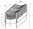
図1は本発明の第1の実施形態の超音波探触子の超音波素子部1のアレイ(配列)方向(図中のAA方向)に直交した(図中のBB方向、短軸方向とも言う)面の断面斜視図を示す。
(Embodiment 1)
FIG. 1 is orthogonal to the array (arrangement) direction (AA direction in the figure) of the ultrasonic element portion 1 of the ultrasonic probe according to the first embodiment of the present invention (both the BB direction and the short axis direction in the figure). Shows a cross-sectional perspective view of the surface.
図1に示すように、超音波の送受信を行う超音波素子部1は、PZT系などの圧電セラミックス等が用いられる超音波を送受信する圧電素子2と超音波を効率よく伝搬させるために用いられ、導電性材料を混入した樹脂やグラファイトなどが用いられる音響整合層3とから構成される電気音響変換部、圧電素子2との間で送信あるいは受信を行うための電気信号を伝達する信号取り出し用第1フレキシブル基板4、信号取り出し用第1フレキシブル基板4と反対の極性の電気信号を扱う信号取り出し用第2フレキシブル基板5、圧電素子2を機械的に保持し、且つ、不要な超音波信号を減衰させる機能を有する背面負荷材6で構成され、信号取り出し用第1フレキシブル基板4、音響整合層3、圧電素子2、信号取り出し用第2フレキシブル基板5、背面負荷材6の順に積層されている。なお、圧電素子2には、積層方向両面に電極が設けられている。
As shown in FIG. 1, an ultrasonic element unit 1 that transmits and receives ultrasonic waves is used to efficiently propagate ultrasonic waves with a
すなわち、この超音波素子部1は、短軸方向(BB)に等間隔だけでなくアレイ方向(AA)にも等間隔に切削などの手段によって切込みを入れ、アレイ方向に数十から数百、短軸方向に数十のエレメントに分割されている。 That is, the ultrasonic element section 1 is cut not only in the short axis direction (BB) but also in the array direction (AA) by cutting at equal intervals by means such as cutting, and several tens to several hundreds in the array direction, Divided into dozens of elements in the minor axis direction.
このように構成される超音波素子部1は、信号取り出し用第1フレキシブル基板4および信号取り出し用第2フレキシブル基板5によって印加される超音波診断装置本体(図示せず)からの起動電圧を圧電素子2の電気・音響変換効果によって、超音波を発生させて、音響整合層3を介して被検体(図示せず)に照射し、また被検体から反射した超音波は音響整合層3を通り、圧電素子2により受信され圧電素子2の電気・音響変換効果によって、電気信号に変換されて信号取り出し用第1フレキシブル基板4および信号取り出し用第2フレキシブル基板5によって取り出され、超音波診断装置本体により演算処理される。なお、圧電素子2と、信号取り出し用第1フレキシブル基板4との間には音響整合層3が積層されているが、音響整合層3は導電性材料を混入した樹脂やグラファイトなどが用いられていることから、圧電素子2と信号取り出し用第1フレキシブル基板4との間の電気信号の伝達は可能である。
The ultrasonic element unit 1 configured in this way piezoelectrically applies a starting voltage from an ultrasonic diagnostic apparatus body (not shown) applied by the first
ここで、アレイ方向の超音波ビームは数十から数百に分割されたエレメントへの超音波診断装置本体からの信号の送受信時間を遅延させ、各エレメントからの超音波信号を合成させた超音波ビームを作り出しており、アレイ方向と直交する方向への超音波ビームは、アレイ方向と直交する方向へ所望の曲率に超音波素子部1を湾曲させて超音波ビームを作り出している。このアレイ方向の超音波ビームと、アレイ方向と直交する方向の超音波ビームの掛け合わせで、良好な超音波画像を抽出している。 Here, the ultrasonic beam in the array direction delays the transmission and reception time of the signal from the ultrasonic diagnostic apparatus main body to the elements divided into several tens to several hundreds, and combines the ultrasonic signals from each element. The ultrasonic beam in the direction orthogonal to the array direction is generated by curving the ultrasonic element unit 1 to a desired curvature in the direction orthogonal to the array direction. A good ultrasonic image is extracted by multiplying the ultrasonic beam in the array direction and the ultrasonic beam in the direction orthogonal to the array direction.
次にこのように動作するアレイ走査型超音波探触子の好ましい作製工程を説明する。 Next, a preferable manufacturing process of the array scanning ultrasonic probe operating in this way will be described.
図2は、積層した状態のアレイ方向と直交する方向から見た断面図を示す。圧電素子2、音響整合層3、信号取り出し用第1フレキシブル基板4の順にエポキシ系の接着剤などを用いて接着、積層する。ここで、エポキシ系の接着剤などを用いて接着する際に、接着材層を極めて薄くすることで、圧電素子2と音響整合層3および、音響整合層3と信号取り出し用第1フレキシブル基板4を各々オーミックコンタクトさせることができて、圧電素子2、音響整合層3、信号取り出し用第1フレキシブル基板4との電気的な接続が得られる。
FIG. 2 is a cross-sectional view seen from a direction orthogonal to the array direction in the stacked state. The
図2においてアレイ方向と平行に圧電素子2の厚さの0.6倍程度の同一ピッチで、圧電素子2を厚さ方向に貫通して、音響整合層3の圧電素子2に接していない面に達する近傍まで、切削などの手段によって数個から数十個の切込み7を設ける。つまり、圧電素子の厚さ寸法(T1)以上でかつ圧電素子の厚さ寸法(T1)に音響整合層の厚さ寸法(T2)を加算した値よりも短い寸法(T3)で圧電素子2側から音響整合層3側へ切込みを設けている。
In FIG. 2, the surface of the
ここで、切削などの手段によって、切込み7を設ける際に圧電素子2や音響整合層3がバラバラにならないように音響整合層3を圧電素子2に接していない面の近傍まで切込みを入れている。図3は切込みを入れた状態のアレイ方向と直交する方向から見た断面図を示す。
Here, by providing means such as cutting, the
図1では、信号取り出し用第1フレキシブル基板4と、音響整合層3と、圧電素子2と、信号取り出し用第2フレキシブル基板5と、背面負荷材6とを積層した状態のものを、図2、図3では、信号取り出し用第1フレキシブル基板4と、音響整合層3と、圧電素子2とを積層した状態のものを示したが、圧電素子2と信号取り出し用第1フレキシブル基板4の間に音響整合層3を複数積層したものでもよい。
In FIG. 1, the one in which the first
次に、図3のユニットにあらかじめ所望の曲率が設けられた背面負荷材6と信号取り出し用第2フレキシブル基板5をエポキシ系の接着剤などを用いて接着、積層させる。この際、切込み7に接着剤が充填されるようにする。
ここで、エポキシ系の接着剤などを用いて接着する際に、接着材層を極めて薄くすることで、圧電素子2と信号取り出し用第2フレキシブル基板5とをオーミックコンタクトさせることができて、圧電素子2、信号取り出し用第2フレキシブル基板5との電気的な接続が得られる。
Next, the
Here, when bonding using an epoxy-based adhesive or the like, the
図4はこの状態のアレイ方向と直交する方向から見た断面図を示す。このとき図3の圧電素子2の信号取り出し用第1フレキシブル基板4側の面から背面負荷材6にあらかじめ形成された曲率とほぼ同じ曲率を持った支持工具(図示せず)用いて加圧しながら接着すると良好な形状を保持できる。
FIG. 4 shows a cross-sectional view as seen from a direction orthogonal to the array direction in this state. At this time, while applying pressure using a support tool (not shown) having a curvature substantially the same as the curvature previously formed on the back
図4のユニットを更にアレイ方向と直交する方向に切削などの手段によって数十から数百のエレメントに分割して、図1の超音波素子部1が完成する。このとき切込み7がアンカー効果を持ち、図4のユニットの接着強度が向上することから、切削による分割が良好におこなわれる。
The unit shown in FIG. 4 is further divided into several tens to several hundreds of elements in a direction orthogonal to the array direction by means such as cutting, thereby completing the ultrasonic element unit 1 shown in FIG. At this time, the
このような手段によれば、図3のユニットを図4のユニットに形成する際に、アレイ方向と直交する方向に一定間隔で圧電素子2を貫通する切込み7を設けていることで、図3のユニットをアレイ方向と直交する方向に曲率を持たせるために機械的に湾曲させることによる、圧電素子2への応力集中は無くなり、圧電素子2が破損するおそれがなくなる。
According to such means, when the unit of FIG. 3 is formed into the unit of FIG. 4, the
なお、本実施の形態では、リニア形状のアレイ型超音波探触子について記載したが、扇形のコンベックス型のアレイ型超音波探触子についても同様の効果がある。 In the present embodiment, the linear array type ultrasonic probe has been described. However, the fan-shaped convex array type ultrasonic probe has the same effect.
以上のことから、本実施形態のアレイ型超音波探触子を用いることで、圧電素子の破損による送信時および受信時の超音波の減少を無くすことができる。つまり、診断画像の感度劣化を改善することができる。 From the above, by using the array-type ultrasonic probe of the present embodiment, it is possible to eliminate the reduction of ultrasonic waves at the time of transmission and reception due to breakage of the piezoelectric element. That is, it is possible to improve sensitivity deterioration of the diagnostic image.
(実施形態2)
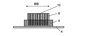
図5は本発明の第2の実施形態の超音波素子部のアレイ方向と直交する方向から見た断面図を示す。
(Embodiment 2)
FIG. 5 is a cross-sectional view of the ultrasonic element unit according to the second embodiment of the present invention as seen from the direction orthogonal to the array direction.
図5の中で、圧電素子8は、音響整合層9や背面負荷材6の部品よりアレイ方向と直交する方向の長さが短い(音響整合層の短軸方向の寸法が、圧電素子の短軸方向の寸法よりも長い)構成となっている。
5, the
図5の超音波素子部は、圧電素子8、音響整合層9、信号取り出し用第1フレキシブル基板4の順にエポキシ系の接着剤などを用いて接着、積層されている。このとき、圧電素子8は、音響整合層9に対してアレイ方向と直交する方向から見て中央部に位置することが望ましい。図6は切込みを入れた段階でのアレイ方向と直交する方向から見た断面図を示す。アレイ方向と平行に圧電素子8の厚さ方向の長さの0.6倍程度の同一ピッチで切込み10を設ける。すなわち、圧電素子8を厚さ方向に貫通して、音響整合層9に圧電素子8に接していない面に達する近傍まで、切削などの手段によって数個から数十個の切込み10を設ける。ここで、切削などの手段によって、切込み10を設ける際に圧電素子8や音響整合層9がバラバラにならないように音響整合層9を圧電素子8に接していない面の近傍まで切込みを入れている。また、このとき、音響整合層9の圧電素子8と接していない部分は、切削などの手段によって切込み10を設けない。
5 is bonded and laminated in the order of the
図5では、信号取り出し用第1フレキシブル基板4と、音響整合層9と、圧電素子8と、信号取り出し用第2フレキシブル基板5と、背面負荷材6とを積層した状態のものを、図6では、信号取り出し用第1フレキシブル基板4と、音響整合層9と、圧電素子8とを積層した状態のものを示したが、圧電素子8と信号取り出し用第1フレキシブル基板4の間に音響整合層9を複数積層したものでもよい。
In FIG. 5, the one in which the first
図6のユニットにあらかじめ所望の曲率が設けられた背面負荷材6と信号取り出し用第2フレキシブル基板5をエポキシ系の接着剤などを用いて接着、積層させ、図5の構成にする。この際、切込み10に接着剤が充填されるようにする。
The
その後、アレイ方向と直交する方向に切削などの手段によって数十から数百のエレメントに分割する。このとき切込み10がアンカー効果を持ち、図5のユニットの接着強度が向上することから、切削による分割が良好におこなわれる。
Then, it is divided into tens to hundreds of elements by means such as cutting in a direction orthogonal to the array direction. At this time, the
このような手段によれば、アレイ方向と直交する方向に一定間隔で圧電素子8を貫通する切込み10を設けていることで、図6のユニットをアレイ方向と直交する方向に曲率を持たせるために機械的に湾曲させることによる、圧電素子8への応力集中は無くなり、圧電素子8が破損してしまうおそれはない。
According to such means, by providing the
なお、本実施の形態は、リニア形状のアレイ型超音波探触子及び、扇形のコンベックス型のアレイ型超音波探触子についても同様の効果がある。 Note that the present embodiment has the same effect with respect to a linear array type ultrasonic probe and a fan-shaped convex array type ultrasonic probe.
以上のことから、本実施形態のアレイ型超音波探触子を用いることで、圧電素子の破損による送信時および受信時の超音波の減少を無くすことができる。つまり、診断画像の感度劣化を改善することができる。 From the above, by using the array-type ultrasonic probe of the present embodiment, it is possible to eliminate the reduction of ultrasonic waves at the time of transmission and reception due to breakage of the piezoelectric element. That is, it is possible to improve sensitivity deterioration of the diagnostic image.
(実施形態3)
図7は本発明の第3の実施形態の超音波素子部のアレイ方向と直交する方向から見た断面図を示す。
(Embodiment 3)
FIG. 7 is a cross-sectional view of the ultrasonic element unit according to the third embodiment of the present invention viewed from a direction orthogonal to the array direction.
図7の中で、圧電素子11は、図5と同様に音響整合層12や背面負荷材6の部品よりアレイ方向と直交する方向の長さが短い構成となっている。
In FIG. 7, the
図7の超音波素子部は、圧電素子11、音響整合層12、信号取り出し用第1フレキシブル基板4の順にエポキシ系の接着剤などを用いて接着、積層されている。このとき、圧電素子11は、音響整合層12に対してアレイ方向と直交する方向から見て中央部に位置することが望ましい。図8は切込みを入れた段階でのアレイ方向と直交する方向から見た断面図を示す。アレイ方向と平行に圧電素子11の厚さ方向の長さの0.6倍程度の同一ピッチで、圧電素子11を厚さ方向に貫通して、音響整合層12の圧電素子11に接していない面に達する近傍まで、切削などの手段によって数個から数十個の切込み13を設ける。ここで、切削などの手段によって、切込み13を設ける際に圧電素子11や音響整合層12がバラバラにならないように音響整合層12を圧電素子11に接していない面の近傍まで切込みを入れている。また、このとき、音響整合層12の圧電素子11と接していない部分にも、同様に切込み13を設ける。
In the ultrasonic element section of FIG. 7, the
図7では、信号取り出し用第1フレキシブル基板4と、音響整合層12と、圧電素子11と、信号取り出し用第2フレキシブル基板5と、背面負荷材6とを積層した状態のものを、図8では、信号取り出し用第1フレキシブル基板4と、音響整合層12と、圧電素子11とを積層した状態のものを示したが、圧電素子11と信号取り出し用第1フレキシブル基板4の間に音響整合層12を複数積層したものでもよい。
In FIG. 7, the first
図8のユニットにあらかじめ所望の曲率が設けられた背面負荷材6と信号取り出し用第2フレキシブル基板5をエポキシ系の接着剤などを用いて接着、積層させ、図7の構成にする。
The
その後、アレイ方向と直交する方向に切削などの手段によって数十から数百のエレメントに分割する。このとき切込み10がアンカー効果を持ち、図5のユニットの接着強度が向上することから、切削による分割が良好におこなわれる。
Then, it is divided into tens to hundreds of elements by means such as cutting in a direction orthogonal to the array direction. At this time, the
このような手段によれば、アレイ方向と直交する方向に一定間隔で圧電素子11を貫通する切込み13を設けていることで、図8のユニットをアレイ方向と直交する方向に曲率を持たせるために機械的に湾曲させることによる、圧電素子11への応力集中は無くなり、圧電素子11が破損してしまうおそれはない。
According to such means, by providing the
なお、本実施の形態は、リニア形状のアレイ型超音波探触子及び、扇形のコンベックス型のアレイ型超音波探触子についても同様の効果がある。 Note that the present embodiment has the same effect with respect to a linear array type ultrasonic probe and a fan-shaped convex array type ultrasonic probe.
以上のことから、本実施形態の超音波探触子を用いることで、圧電素子の破損による送信時および受信時の超音波の減少を無くすことができる。つまり、診断画像の感度劣化を改善することができる。 From the above, by using the ultrasonic probe of the present embodiment, it is possible to eliminate a decrease in ultrasonic waves at the time of transmission and reception due to damage of the piezoelectric element. That is, it is possible to improve sensitivity deterioration of the diagnostic image.
(実施形態4)
図9は本発明の第4の実施形態の超音波素子部のアレイ方向と直交する方向から見た断面図を示す。
(Embodiment 4)
FIG. 9 shows a cross-sectional view of the ultrasonic element portion according to the fourth embodiment of the present invention as seen from the direction orthogonal to the array direction.
図9の中で音響整合層15は圧電素子14に接していない面から厚さ方向に圧電素子15が送出する超音波の1/9波長未満の厚さを残し(同図d)、アレイ方向と直交する方向に、一定の間隔で切込み16が設けられている。
In FIG. 9, the
図9の超音波素子部は、圧電素子14、音響整合層15、信号取り出し用第1フレキシブル基板4の順にエポキシ系の接着剤などを用いて接着、積層されている。図10は製作過程でのアレイ方向と直交する方向から見た断面図を示し、図11は音響整合層15を圧電素子14に接していない面から厚さ方向に1/9波長未満の厚さを残した図10のA部分の拡大図を示す。すなわち、アレイ方向と平行に圧電素子14の厚さ方向の長さの0.6倍程度の同一ピッチで、圧電素子14を厚さ方向に切断して、音響整合層15を圧電素子14に接していない面から厚さ方向に1/9波長未満の厚さを残し、切削などの手段によって数個から数十個の切込み16を設ける。ここで、切削などの手段によって、切込み16を設ける際に圧電素子14や音響整合層15がバラバラにならないように音響整合層15を圧電素子14に接していない面から厚さ方向に1/9波長未満の厚さを残している。また、音響整合層15を圧電素子14に接していない面の1/9波長未満の厚さを残す(図11d)ことで、アレイ方向と直交する方向に均一な曲率を形成できる。
In the ultrasonic element section of FIG. 9, the
図9では、信号取り出し用第1フレキシブル基板4と、音響整合層15と、圧電素子14と、信号取り出し用第2フレキシブル基板5と、背面負荷材6とを積層した状態のものを、図10では、信号取り出し用第1フレキシブル基板4と、音響整合層15と、圧電素子14とを積層した状態のものを示したが、圧電素子14と信号取り出し用第1フレキシブル基板4の間に音響整合層15を複数積層したものでもよい。
In FIG. 9, the one in which the first
図10のユニットにあらかじめ所望の曲率が設けられた背面負荷材6と信号取り出し用第2フレキシブル基板5をエポキシ系の接着剤などを用いて接着、積層させ、図9の構成にする。この際、切込み16に接着剤が充填されるようにする。このとき、音響整合層15は切込み16から圧電素子14に接していない面までの厚さが1/9波長未満の非常に薄いことから、図10のユニットはあらかじめ背面負荷材6に施された所望の曲率に倣い、接着、積層され、良好な形状に形成される。その後、アレイ方向と直交する方向に切削などの手段によって数十から数百のエレメントに分割する。このとき図9の切込み16がアンカー効果を持ち、図9のユニットの接着強度が向上することから、アレイ方向と直交する方向の切削による分割が良好におこなわれる。図12は、図9あるいは図11に示した寸法dごとの、図9の信号取り出し用第1フレキシブル基板4側の面から、BB方向の曲率半径を測定した特性データ図であり、曲率半径のバラツキを表している。すなわち、切込み16により音響整合層15を圧電素子14に接していない面から1/18波長の厚さを残したもの、1/12波長の厚さを残したもの1/9波長の厚さを残したものをそれぞれ比較すると、1/9波長の厚さを残したものは曲率半径のバラツキが非常に大きくなり、BB方向の超音波ビームが不均一になってしまうが、それより小さいものは良好な特性となり、特に1/18波長未満の厚さを残したものは優れていることがわかる。
The
このような手段によれば、図10のユニットをアレイ方向と直交する方向に曲率を持たせるために機械的に湾曲させることによる、圧電素子14への応力集中は無く、圧電素子14が破損してしまうことは発生しない、且つ、良好にアレイ方向と直交する方向に曲率を形成できる。
According to such means, there is no stress concentration on the
なお、本実施の形態では、圧電素子14は、音響整合層15や背面負荷材6の部品とアレイ方向と直交する方向の長さが同じであるが、圧電素子14が、音響整合層15や背面負荷材6の部品よりアレイ方向と直交する方向の長さが短い構成でも、圧電素子14と接していない部分に切込み16を設けない場合(図5参照)や、切込み16を設けた場合(図7参照)に、同様の効果がある。
In the present embodiment, the
なお、本実施の形態は、リニア形状のアレイ型超音波探触子及び、扇形のコンベックス型のアレイ型超音波探触子についても同様の効果がある。 Note that the present embodiment has the same effect with respect to a linear array type ultrasonic probe and a fan-shaped convex array type ultrasonic probe.
以上のことから、本実施形態の超音波探触子を用いることで、圧電素子の破損による送信時および受信時の超音波の減少を無くすことができる。つまり、診断画像の感度劣化を改善することができる。さらに、アレイ走査型超音波探触子は所望の曲率に良好に形成することができる。 From the above, by using the ultrasonic probe of the present embodiment, it is possible to eliminate a decrease in ultrasonic waves at the time of transmission and reception due to damage of the piezoelectric element. That is, it is possible to improve sensitivity deterioration of the diagnostic image. Furthermore, the array scanning ultrasonic probe can be satisfactorily formed with a desired curvature.
以上のように、本発明にかかるアレイ走査型超音波探触子は、圧電素子の破損による送信時および受信時の超音波の減少を無くすことができる。つまり、診断画像の感度劣化を改善するという効果を有し、圧電素子と、音響整合層と、信号取り出し用フレキシブル基板とからなるアレイ走査型超音波探触子に係わり、アレイ型超音波探触子の圧電素子の破損による特性劣化を改善させることができるアレイ走査型超音波探触子等として有用である。 As described above, the array scanning ultrasonic probe according to the present invention can eliminate a decrease in ultrasonic waves at the time of transmission and reception due to breakage of the piezoelectric element. In other words, it has the effect of improving sensitivity degradation of diagnostic images, and is related to an array scanning ultrasonic probe comprising a piezoelectric element, an acoustic matching layer, and a flexible substrate for signal extraction. This is useful as an array scanning ultrasonic probe or the like that can improve characteristic deterioration due to breakage of the piezoelectric element of the child.
Claims (7)
前記複数の圧電素子との間で送信あるいは受信のための電気信号を伝達する信号取り出し用第1のフレキシブル基板と、
前記複数の圧電素子との間で送信あるいは受信のための電気信号を伝送する信号取り出し用第2のフレキシブル基板を備え、
前記信号取り出し用第1のフレキシブル基板は前記音響整合層の前記圧電素子が形成されている面側とは反対の面側に形成され、
前記信号取り出し用第2のフレキシブル基板は、前記圧電素子の前記音響整合層が積層されている面とは反対の面側に接着剤により接着して形成され、
前記複数の圧電素子のそれぞれの厚さ方向に前記それぞれの圧電素子を貫通してこれに積層された対応する前記音響整合層に至る切込みが前記配列方向と並行であって且つ前記配列方向に対して直交する方向に一定間隔で複数設けられ、
前記切り込みには、前記接着剤が充填されている超音波探触子。 An electroacoustic transducer formed by arranging a plurality of piezoelectric elements, each of which is an electroacoustic transducer, and a plurality of acoustic matching layers stacked on each of the plurality of piezoelectric elements, in a predetermined direction;
A first flexible substrate for signal extraction that transmits electrical signals for transmission or reception to and from the plurality of piezoelectric elements ;
A second flexible substrate for signal extraction that transmits an electrical signal for transmission or reception between the plurality of piezoelectric elements ;
The first flexible substrate for signal extraction is formed on the surface side of the acoustic matching layer opposite to the surface side on which the piezoelectric element is formed,
The second flexible substrate for signal extraction is formed by adhering to the surface opposite to the surface on which the acoustic matching layer of the piezoelectric element is laminated,
Incisions that penetrate the respective piezoelectric elements in the thickness directions of the plurality of piezoelectric elements and reach the corresponding acoustic matching layers stacked on the piezoelectric elements are parallel to the arrangement direction and with respect to the arrangement direction. Are provided at regular intervals in the orthogonal direction ,
An ultrasonic probe in which the cut is filled with the adhesive .
前記圧電素子が湾曲した状態で、前記音響整合層の前記配列方向に対して直交する方向の両端部が前記圧電素子の前記配列方向に対して直行する方向の両端部よりも突出している請求項3に記載の超音波探触子。 The piezoelectric element is curved in a direction perpendicular to the arrangement direction,
The both ends of the acoustic matching layer in a direction orthogonal to the arrangement direction of the acoustic matching layers protrude from both ends of the piezoelectric element in a direction orthogonal to the arrangement direction in a state where the piezoelectric elements are curved. 3. The ultrasonic probe according to 3.
Priority Applications (1)
| Application Number | Priority Date | Filing Date | Title |
|---|---|---|---|
| JP2009525289A JP5477630B2 (en) | 2007-08-01 | 2008-07-31 | Array scanning ultrasonic probe |
Applications Claiming Priority (4)
| Application Number | Priority Date | Filing Date | Title |
|---|---|---|---|
| JP2007200490 | 2007-08-01 | ||
| JP2007200490 | 2007-08-01 | ||
| JP2009525289A JP5477630B2 (en) | 2007-08-01 | 2008-07-31 | Array scanning ultrasonic probe |
| PCT/JP2008/002059 WO2009016843A1 (en) | 2007-08-01 | 2008-07-31 | Array scanning type ultrasound probe |
Publications (2)
| Publication Number | Publication Date |
|---|---|
| JPWO2009016843A1 JPWO2009016843A1 (en) | 2010-10-14 |
| JP5477630B2 true JP5477630B2 (en) | 2014-04-23 |
Family
ID=40304085
Family Applications (1)
| Application Number | Title | Priority Date | Filing Date |
|---|---|---|---|
| JP2009525289A Active JP5477630B2 (en) | 2007-08-01 | 2008-07-31 | Array scanning ultrasonic probe |
Country Status (4)
| Country | Link |
|---|---|
| US (2) | US8084922B2 (en) |
| EP (1) | EP2165650B1 (en) |
| JP (1) | JP5477630B2 (en) |
| WO (1) | WO2009016843A1 (en) |
Families Citing this family (7)
| Publication number | Priority date | Publication date | Assignee | Title |
|---|---|---|---|---|
| WO2009016843A1 (en) * | 2007-08-01 | 2009-02-05 | Panasonic Corporation | Array scanning type ultrasound probe |
| JP5954773B2 (en) * | 2012-03-13 | 2016-07-20 | 東芝メディカルシステムズ株式会社 | Ultrasonic probe and method for manufacturing ultrasonic probe |
| JP5474261B1 (en) * | 2012-05-12 | 2014-04-16 | 京セラ株式会社 | Piezoelectric actuator, piezoelectric vibration device, and portable terminal |
| CA3100826C (en) | 2018-06-04 | 2023-09-26 | Ge Sensing & Inspection Technologies Gmbh | Condition monitoring of ultrasonic transducers and probes |
| JP2020005027A (en) * | 2018-06-25 | 2020-01-09 | パナソニックIpマネジメント株式会社 | Ultrasonic sensor |
| EP3694007A1 (en) * | 2019-02-05 | 2020-08-12 | Koninklijke Philips N.V. | Sensor comprising an interconnect having a carrier film |
| EP3907769A1 (en) * | 2020-05-08 | 2021-11-10 | Koninklijke Philips N.V. | Sensor comprising an interconnect and an interventional medical device using the same |
Citations (6)
| Publication number | Priority date | Publication date | Assignee | Title |
|---|---|---|---|---|
| JPH11317999A (en) * | 1998-05-01 | 1999-11-16 | Aloka Co Ltd | Ultrasonic wave vibrator and its manufacture |
| JP2002224104A (en) * | 2001-01-30 | 2002-08-13 | Olympus Optical Co Ltd | Ultrasonic array vibrator |
| JP2005086458A (en) * | 2003-09-08 | 2005-03-31 | Olympus Corp | Array type ultrasonic vibrator |
| JP2005296127A (en) * | 2004-04-07 | 2005-10-27 | Toshiba Corp | Ultrasonic probe and ultrasonic diagnostic device |
| JP2006087464A (en) * | 2004-09-21 | 2006-04-06 | Olympus Corp | Ultrasonic oscillator |
| JP2006122657A (en) * | 2004-09-29 | 2006-05-18 | Aloka Co Ltd | Ultrasonic diagnostic apparatus and probe |
Family Cites Families (9)
| Publication number | Priority date | Publication date | Assignee | Title |
|---|---|---|---|---|
| JPS6032396B2 (en) | 1981-05-14 | 1985-07-27 | 横河電機株式会社 | Manufacturing method of conformal array resonator |
| US5423220A (en) * | 1993-01-29 | 1995-06-13 | Parallel Design | Ultrasonic transducer array and manufacturing method thereof |
| US5792058A (en) * | 1993-09-07 | 1998-08-11 | Acuson Corporation | Broadband phased array transducer with wide bandwidth, high sensitivity and reduced cross-talk and method for manufacture thereof |
| US5638822A (en) * | 1995-06-30 | 1997-06-17 | Hewlett-Packard Company | Hybrid piezoelectric for ultrasonic probes |
| US6117083A (en) * | 1996-02-21 | 2000-09-12 | The Whitaker Corporation | Ultrasound imaging probe assembly |
| JP3625564B2 (en) * | 1996-02-29 | 2005-03-02 | 株式会社日立メディコ | Ultrasonic probe and manufacturing method thereof |
| US6043589A (en) * | 1997-07-02 | 2000-03-28 | Acuson Corporation | Two-dimensional transducer array and the method of manufacture thereof |
| EP2305124B1 (en) | 2004-09-21 | 2012-01-25 | Olympus Corporation | Ultrasonic transducer array |
| WO2009016843A1 (en) * | 2007-08-01 | 2009-02-05 | Panasonic Corporation | Array scanning type ultrasound probe |
-
2008
- 2008-07-31 WO PCT/JP2008/002059 patent/WO2009016843A1/en active Application Filing
- 2008-07-31 JP JP2009525289A patent/JP5477630B2/en active Active
- 2008-07-31 EP EP08790323.3A patent/EP2165650B1/en not_active Not-in-force
- 2008-07-31 US US12/670,329 patent/US8084922B2/en not_active Expired - Fee Related
-
2011
- 2011-11-23 US US13/303,333 patent/US8237336B2/en active Active
Patent Citations (6)
| Publication number | Priority date | Publication date | Assignee | Title |
|---|---|---|---|---|
| JPH11317999A (en) * | 1998-05-01 | 1999-11-16 | Aloka Co Ltd | Ultrasonic wave vibrator and its manufacture |
| JP2002224104A (en) * | 2001-01-30 | 2002-08-13 | Olympus Optical Co Ltd | Ultrasonic array vibrator |
| JP2005086458A (en) * | 2003-09-08 | 2005-03-31 | Olympus Corp | Array type ultrasonic vibrator |
| JP2005296127A (en) * | 2004-04-07 | 2005-10-27 | Toshiba Corp | Ultrasonic probe and ultrasonic diagnostic device |
| JP2006087464A (en) * | 2004-09-21 | 2006-04-06 | Olympus Corp | Ultrasonic oscillator |
| JP2006122657A (en) * | 2004-09-29 | 2006-05-18 | Aloka Co Ltd | Ultrasonic diagnostic apparatus and probe |
Also Published As
| Publication number | Publication date |
|---|---|
| US8084922B2 (en) | 2011-12-27 |
| EP2165650B1 (en) | 2017-07-19 |
| US8237336B2 (en) | 2012-08-07 |
| WO2009016843A1 (en) | 2009-02-05 |
| EP2165650A1 (en) | 2010-03-24 |
| EP2165650A4 (en) | 2015-04-22 |
| US20100187952A1 (en) | 2010-07-29 |
| US20120060613A1 (en) | 2012-03-15 |
| JPWO2009016843A1 (en) | 2010-10-14 |
Similar Documents
| Publication | Publication Date | Title |
|---|---|---|
| JP5477630B2 (en) | Array scanning ultrasonic probe | |
| US20200061671A1 (en) | Ultrasound transducer and method for making the same | |
| EP1728563B1 (en) | Ultrasonic probe and ultrasonic probe manufacturing method | |
| US9321082B2 (en) | Ultrasonic transducer, manufacturing method thereof, and ultrasonic probe | |
| KR20110088384A (en) | Ultrasound transducer, ultrasound probe, and a method for manufacturing ultrasound transducers | |
| CN109804643B (en) | Ultrasonic probe and method for manufacturing ultrasonic probe | |
| JP2009082385A (en) | Ultrasonic probe | |
| JP2008085537A (en) | Ultrasonic probe | |
| JP2009082612A (en) | Ultrasonic probe and piezoelectric transducer | |
| JP5725978B2 (en) | Ultrasonic probe | |
| KR101491801B1 (en) | Ultrasonic transducer and method of manufacturing the same | |
| JP2012249777A5 (en) | ||
| JP3436486B2 (en) | Ultrasonic vibrator and manufacturing method thereof | |
| JP4769127B2 (en) | Ultrasonic probe and ultrasonic probe manufacturing method | |
| JP2008302044A (en) | Ultrasonic probe, ultrasonograph using it, and ultrasonic flaw detector | |
| KR20160038390A (en) | Ultrasonic transducer and method for fabricating the same | |
| JP2010258602A (en) | Ultrasonic probe and method of manufacturing the same | |
| US6333590B1 (en) | Ultrasonic transducer having laminate structure, ultrasonic probe and production method thereof | |
| JP4439851B2 (en) | Array-type ultrasonic probe and manufacturing method thereof | |
| EP3895812B1 (en) | Curved shape piezoelectric transducer and method for manufacturing the same | |
| JP2001276060A (en) | Ultrasonic probe | |
| JP2006262149A (en) | Ultrasonic probe and ultrasonic diagnostic device | |
| JP5530994B2 (en) | Ultrasonic probe and manufacturing method thereof | |
| JP2023071213A (en) | Laminate type composite vibrator | |
| JP2016152580A (en) | Ultrasound probe and method of manufacturing the same |
Legal Events
| Date | Code | Title | Description |
|---|---|---|---|
| A621 | Written request for application examination |
Free format text: JAPANESE INTERMEDIATE CODE: A621 Effective date: 20110613 |
|
| A131 | Notification of reasons for refusal |
Free format text: JAPANESE INTERMEDIATE CODE: A131 Effective date: 20130402 |
|
| A521 | Request for written amendment filed |
Free format text: JAPANESE INTERMEDIATE CODE: A523 Effective date: 20130527 |
|
| A131 | Notification of reasons for refusal |
Free format text: JAPANESE INTERMEDIATE CODE: A131 Effective date: 20130702 |
|
| A521 | Request for written amendment filed |
Free format text: JAPANESE INTERMEDIATE CODE: A523 Effective date: 20130826 |
|
| TRDD | Decision of grant or rejection written | ||
| A01 | Written decision to grant a patent or to grant a registration (utility model) |
Free format text: JAPANESE INTERMEDIATE CODE: A01 Effective date: 20140107 |
|
| A711 | Notification of change in applicant |
Free format text: JAPANESE INTERMEDIATE CODE: A711 Effective date: 20140121 |
|
| A61 | First payment of annual fees (during grant procedure) |
Free format text: JAPANESE INTERMEDIATE CODE: A61 Effective date: 20140129 |
|
| R150 | Certificate of patent or registration of utility model |
Ref document number: 5477630 Country of ref document: JP Free format text: JAPANESE INTERMEDIATE CODE: R150 |