JP5465727B2 - Rolling equipment for rolling strips - Google Patents
Rolling equipment for rolling strips Download PDFInfo
- Publication number
- JP5465727B2 JP5465727B2 JP2011528226A JP2011528226A JP5465727B2 JP 5465727 B2 JP5465727 B2 JP 5465727B2 JP 2011528226 A JP2011528226 A JP 2011528226A JP 2011528226 A JP2011528226 A JP 2011528226A JP 5465727 B2 JP5465727 B2 JP 5465727B2
- Authority
- JP
- Japan
- Prior art keywords
- coil
- transport means
- coiler
- rolling equipment
- reversible
- Prior art date
- Legal status (The legal status is an assumption and is not a legal conclusion. Google has not performed a legal analysis and makes no representation as to the accuracy of the status listed.)
- Expired - Fee Related
Links
Images

Classifications
-
- B—PERFORMING OPERATIONS; TRANSPORTING
- B21—MECHANICAL METAL-WORKING WITHOUT ESSENTIALLY REMOVING MATERIAL; PUNCHING METAL
- B21B—ROLLING OF METAL
- B21B39/00—Arrangements for moving, supporting, or positioning work, or controlling its movement, combined with or arranged in, or specially adapted for use in connection with, metal-rolling mills
-
- B—PERFORMING OPERATIONS; TRANSPORTING
- B21—MECHANICAL METAL-WORKING WITHOUT ESSENTIALLY REMOVING MATERIAL; PUNCHING METAL
- B21C—MANUFACTURE OF METAL SHEETS, WIRE, RODS, TUBES OR PROFILES, OTHERWISE THAN BY ROLLING; AUXILIARY OPERATIONS USED IN CONNECTION WITH METAL-WORKING WITHOUT ESSENTIALLY REMOVING MATERIAL
- B21C47/00—Winding-up, coiling or winding-off metal wire, metal band or other flexible metal material characterised by features relevant to metal processing only
- B21C47/24—Transferring coils to or from winding apparatus or to or from operative position therein; Preventing uncoiling during transfer
-
- B—PERFORMING OPERATIONS; TRANSPORTING
- B21—MECHANICAL METAL-WORKING WITHOUT ESSENTIALLY REMOVING MATERIAL; PUNCHING METAL
- B21B—ROLLING OF METAL
- B21B1/00—Metal-rolling methods or mills for making semi-finished products of solid or profiled cross-section; Sequence of operations in milling trains; Layout of rolling-mill plant, e.g. grouping of stands; Succession of passes or of sectional pass alternations
- B21B1/22—Metal-rolling methods or mills for making semi-finished products of solid or profiled cross-section; Sequence of operations in milling trains; Layout of rolling-mill plant, e.g. grouping of stands; Succession of passes or of sectional pass alternations for rolling plates, strips, bands or sheets of indefinite length
- B21B1/30—Metal-rolling methods or mills for making semi-finished products of solid or profiled cross-section; Sequence of operations in milling trains; Layout of rolling-mill plant, e.g. grouping of stands; Succession of passes or of sectional pass alternations for rolling plates, strips, bands or sheets of indefinite length in a non-continuous process
- B21B1/32—Metal-rolling methods or mills for making semi-finished products of solid or profiled cross-section; Sequence of operations in milling trains; Layout of rolling-mill plant, e.g. grouping of stands; Succession of passes or of sectional pass alternations for rolling plates, strips, bands or sheets of indefinite length in a non-continuous process in reversing single stand mills, e.g. with intermediate storage reels for accumulating work
- B21B1/36—Metal-rolling methods or mills for making semi-finished products of solid or profiled cross-section; Sequence of operations in milling trains; Layout of rolling-mill plant, e.g. grouping of stands; Succession of passes or of sectional pass alternations for rolling plates, strips, bands or sheets of indefinite length in a non-continuous process in reversing single stand mills, e.g. with intermediate storage reels for accumulating work by cold-rolling
-
- B—PERFORMING OPERATIONS; TRANSPORTING
- B21—MECHANICAL METAL-WORKING WITHOUT ESSENTIALLY REMOVING MATERIAL; PUNCHING METAL
- B21B—ROLLING OF METAL
- B21B15/00—Arrangements for performing additional metal-working operations specially combined with or arranged in, or specially adapted for use in connection with, metal-rolling mills
-
- B—PERFORMING OPERATIONS; TRANSPORTING
- B21—MECHANICAL METAL-WORKING WITHOUT ESSENTIALLY REMOVING MATERIAL; PUNCHING METAL
- B21B—ROLLING OF METAL
- B21B39/00—Arrangements for moving, supporting, or positioning work, or controlling its movement, combined with or arranged in, or specially adapted for use in connection with, metal-rolling mills
- B21B39/004—Transverse moving
Description
この発明は、二つ或いは三つのコイラと二つのコイラの間の少なくとも一つのロールスタンドとを備え且つ圧延材のコイルをそれぞれのコイル引渡しステーションへ供給するか、或いは運び去る付属されたコイル輸送手段を備え且つ両コイル引渡しステーションの間にコイルを輸送する横輸送手段を備える帯状圧延材を圧延する圧延設備に関する。 The invention relates to an associated coil transport means comprising two or three coilers and at least one roll stand between the two coilers, and supplying or carrying the coil of rolled material to the respective coil delivery station. And a rolling facility for rolling a strip-shaped rolled material having a lateral transport means for transporting a coil between both coil delivery stations.
この種の圧延設備は、欧州特許第0618018号明細書(特許文献1)から知られている。 This type of rolling equipment is known from EP 0618018 (Patent Document 1).
公知の圧延設備は、選択された巻戻しコイラ、少なくとも一つの他のコイラ、可逆コイラとして用いられる少なくとも二つのコイラを装備されている。すべての到来するコイルが巻戻しコイラに与えられる。出発するコイルが他のコイラ或いは両他のコイラから取り出される(巻上げコイラ)。到達するコイルがコイラに載せられ、このコイラから取り出される圧延設備が存在する。このコイラでは巻戻しコイラと巻上げコイラが取り扱われている。巻戻しと巻上げするのに用いられるコイラが可逆コイラと呼ばれる。 The known rolling equipment is equipped with a selected unwinding coiler, at least one other coiler, and at least two coilers used as reversible coilers. All incoming coils are fed to the rewind coiler. The starting coil is taken out from the other coiler or from both other coilers (winding coiler). There is a rolling facility in which the reaching coil is placed on a coiler and taken out from the coiler. In this coiler, a rewinding coiler and a winding coiler are handled. The coiler used for rewinding and winding is called a reversible coiler.
出発するコイルが両巻上げコイラの一方からそれぞれにコイル輸送カーによって取り出される。このワゴンは、例えばコイル計量器、コイル結束機、コイルマーク付け機、コイル検査部などのような他の出口装置までコイルを輸送する。コイルが第一コイル輸送カーから取り出され、他のコイル輸送カーに或いは他の輸送装置に引渡される。 The starting coil is removed from one of the winding coils by a coil transport car. The wagon transports the coil to other outlet devices such as a coil meter, coil binding machine, coil marking machine, coil inspection unit and the like. The coil is removed from the first coil transport car and delivered to another coil transport car or to another transport device.
両巻上げコイラの各々が固有の輸送出口装置を装備していて、これは、両巻上げコイラの輸送出口装置が分離されていることを意味する。 Each of the winding coilers is equipped with a unique transportation outlet device, which means that the transportation outlet devices of both winding coils are separated.
この発明の課題は、簡単に構成されていて、比較に僅かな構成部材から成る圧延設備を創作することである。それにより費用が節約され、高い輸送効率が達成される。 The object of the present invention is to create a rolling installation which is simple in construction and comprises only a few components for comparison. This saves costs and achieves high transport efficiency.
「この発明によると、この課題は、前記種類の圧延設備では、コイル輸送のために、共通の輸送出口装置が下流に配置されていることによって、解決される。」を「コイル引渡しステーションの下流に唯一の共通コイル輸送手段が配置されていて、その共通コイル輸送手段によってコイルが横輸送手段から輸送できるか、或いはこの横輸送手段まで輸送できるように構成されており、かつ共通コイル輸送手段が可逆コイラの軸線方向に或いは可逆コイラの軸線方向に対して垂直に移行できるように構成されていることによって解決される。」と補正する。 “According to the present invention, this problem is solved by arranging a common transport outlet device downstream for coil transport in the kind of rolling equipment,” “ downstream of the coil delivery station .” Is arranged so that the coil can be transported from or to the lateral transport means by the common coil transport means, and the common coil transport means is It is solved by being configured to be able to move perpendicularly to the axial direction of the reversible coiler or to the axial direction of the reversible coiler .
横輸送手段はコイルを共通の搬入装置、搬出装置、入口装置と出口装置の間に輸送する。 The lateral transport means transports the coil between a common loading device, unloading device, inlet device and outlet device.
この発明による輸送ロジスティクスは、横輸送手段、特に横移動カーを装備している。横移動カーは、第一コイル輸送手段、特に両可逆コイラの一方と横移動カーの間を往復するコイル輸送手段と横移動カーの下流に配置されたコイル輸送手段との間でコイルを輸送するのに用いられる。それは別のコイル輸送手段であるか、或いはけれどもこの機能がコイラのコイル輸送手段も受け取る。 The transportation logistics according to the invention is equipped with lateral transportation means, in particular laterally moving cars. Lateral movement car, first coil means of transport, in particular for transporting coil between the coil transport means disposed downstream of the coil transport means and the horizontal moving car reciprocates between the one and the lateral movement car both reversible coiler Used for It is another coil transport, or though this function also receives the coiler's coil transport.
横移動カーの下流に配置されたコイル輸送手段は、共通で唯一のコイル輸送手段として、特にコイル輸送手段として横移動カーと共通の出口装置の間に用いられる。出口装置は、例えばコイル計量器、コイル結束機、コイルマーク付け機、コイル検査などである。適切に柔軟な移行可能な横輸送手段の使用によって、コイル輸送手段と入口/出口装置が削減される。この場合に、引渡しステーションが横移動カーの輸送範囲内の任意の箇所に配置されている。けれども、好ましくは引渡しステーションは、コイルがコイラの下流に配置されたコイル物輸送手段から横移動カーへ引き渡される箇所に配置されている。 The coil transportation means arranged downstream of the lateral movement car is used as a common and only coil transportation means, in particular between the lateral movement car and the common outlet device as a coil transportation means. The exit device is, for example, a coil meter, a coil binding machine, a coil marking machine, a coil inspection, or the like. By using a suitably flexible transposable lateral transport means, coil transport means and inlet / outlet devices are reduced. In this case, the delivery station is arranged at an arbitrary position within the transport range of the laterally moving car. However, the delivery station is preferably arranged at a point where the coil is delivered from the coiled article transportation means arranged downstream of the coiler to the lateral movement car.
好ましい更なる実施態様は、従属請求項、明細書と図面から明らかになる。 Preferred further embodiments emerge from the dependent claims, the description and the drawings.
好ましい形式では、横輸送が巻戻しコイラにまで行われることが企図されている。それにより巻戻しコイラ輸送の際に固有のコイル輸送手段が付属される。 In the preferred form, it is contemplated that the lateral transport will take place to the rewind coiler. As a result, a unique coil transportation means is attached during the rewinding coiler transportation.
好ましくは、この場合に横輸送手段が可逆コイラに付属されたコイル輸送手段の間並びにこのコイル輸送手段と巻戻しコイラに付属されたコイル輸送手段の間に輸送できる。これは圧延設備の追加的柔軟性を生み、というのは、コイルが可逆スタンドに両側面から供給し、それら側面から搬入されて、コイラにまで輸送され得るからである。 Preferably, in this case, the lateral transport means can be transported between the coil transport means attached to the reversible coiler and between the coil transport means and the coil transport means attached to the unwinding coiler. This creates additional flexibility in the rolling equipment, because the coils can be fed to the reversible stand from both sides, loaded from these sides and transported to the coiler.
この発明の他の好ましい構成により、横輸送手段の下流に唯一の共通のコイル輸送手段が配置され、そのコイル輸送手段によってコイルが横輸送手段から運び去られるか、或いはこの横輸送手段にまで輸送される。それによりこの場合には、共通のコイル輸送手段が巻戻しコイラにまで輸送されなければならないか、或いはこの巻戻しコイラから運び去られなければならないコイルも輸送する。」 According to another preferred configuration of the invention , only one common coil transport means is arranged downstream of the lateral transport means, so that the coils are carried away from the lateral transport means or transported to this lateral transport means. Is done . Thereby, in this case, a common coil transport means must also be transported to the rewinding coiler or a coil that must be transported away from this rewinding coiler. "
同様に、唯一の共通のコイル輸送手段の使用は、可逆コイラに共通の出口装置、特に計量器、コイル結束機、コイルマーク付け機、などが付属されている。 Similarly, the use of the only common coil transport means is accompanied by a common outlet device for the reversible coiler, in particular a meter, a coil binding machine, a coil marking machine, and the like.
180°だけコイルを回転させる少なくとも一つの回転装置が圧延設備の現実の或いは選択された圧延方向やコイルの配列に依存して出口に存在するときに、設備の柔軟性がなお更に高められる。 When at least one rotating device for rotating the coil by 180 ° is present at the outlet, depending on the actual or selected rolling direction of the rolling equipment and the coil arrangement, the flexibility of the equipment is even further increased.
この場合には、少なくとも一つの回転装置が好ましくは横移動カー或いは少なくとも一つのコイル輸送手段、特に共通のコイル輸送手段の少なくとも一方に一体化される。 In this case, at least one rotating device is preferably integrated into at least one of the laterally moving car or at least one coil transport means, in particular a common coil transport means.
この発明の実施態様には、共通のコイル輸送手段が両可逆コイラに付属されたコイル輸送手段の一方の延長部に、或いは横輸送手段の輸送路に関する任意の位置に接続されていることが企図されている。 In an embodiment of the invention, it is contemplated that a common coil transport means is connected to one extension of the coil transport means attached to both reversible coils, or to any position with respect to the transport path of the lateral transport means. Has been.
この発明の他の好ましい実施態様は、共通のコイル輸送手段が可逆コイラの軸線方向に或いは可逆コイラの軸線方向と垂直に輸送されることにある。 Another preferred embodiment of the invention is that the common coil transport means is transported in the axial direction of the reversible coiler or perpendicular to the axial direction of the reversible coiler.
多数の共通のコイル輸送手段の実施態様が存在し、これらは例えばウオーキングビームとして或いはコイル輸送手段として形成されている。 There are a number of common coil transport embodiments which are formed, for example, as walking beams or as coil transport means.
横輸送手段がみずからコイルを直接に収容するコイル引渡しステーションとして形成されて機能を果たすならば、これは、コイル引渡しステーションが独自の静止不動装置として省略され得る利点を有する。コイルは直接にコイル輸送手段から横輸送手段に移されるか、或いはこの横輸送手段により受けられ、静止不動コイル引渡しステーションに一時貯蔵されないように使用する。 This has the advantage that the coil delivery station can be omitted as its own stationary stationary device if the lateral transport means is formed and functions as a coil delivery station that directly receives the coil. The coil is either transferred directly from the coil transport means to the lateral transport means or is received by this lateral transport means and used so that it is not temporarily stored in the stationary stationary coil delivery station.
次に、この発明は、図面に基づいて実施態様で詳細に説明される。 Next, the present invention will be described in detail in embodiments based on the drawings.
この発明による圧延設備が二つ或いは三つのコイラ、即ちコイラ1、5と20を包含する。
The rolling equipment according to the invention includes two or three coilers, namely
コイラ1は、巻戻しコイラとして利用され得る。コイラ5と20は巻戻しコイラ、段付きコイラと可逆コイラとして利用され得る。
The
ロールスタンド8、13が一方向に限られた駆動で並びに可逆駆動で稼働される。ロールスタンドはそれぞれにワークロール10と11或いは15、16並びにバックアップロール9と12或いは14と17を包含する。ロールスタンド8、13はさらに、ここに図示されていないロール、例えば中間ロールを包含する。両可逆スタンドの間にストリップガイドロールが存在し、例えば押さえロール8、9とストリップ張力測定ローラを存在する。
The roll stands 8 and 13 are operated by driving limited in one direction and by reversible driving. The roll stands include
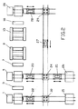
各両コイラ5と20からそれぞれ一つの輸送路がコイル輸送カー23或いは28(図2)により引渡しステーション24或いは29を介して一つの横輸送路まで案内され、その横輸送路の上を横移動カー27が移動する。引渡しステーション24、29において結束物移動カー23、28がそのコイルを横移動カー27に引渡しする。横移動カー27は同時に結束物を180°だけ垂直軸に関して回転させる可能性を提供するから、コイルをコイラ20から搬入する可能性を提供し、コイルを引き続いてコイラ5まで連れ戻され、そこに新たに装填するので、コイルがそこで再びコイルヘッドの正しい位置を有する。
From each of the
他方、コイルが横移動カー27から引渡しステーション24を介して共通のコイル輸送手段25に引き渡され得る。このコイル輸送手段から圧延されたコイルがコイラ5、20に共通の出口装置或いはコイル保管場所26に引き渡される。
On the other hand, the coils can be delivered from the
コイラ1には、コイル輸送カー22を備える輸送路が付属されていて、このコイル輸送カーがコイラ1と出口装置或いは保管装置21の間に前後移行する。横移動カー27の輸送路が引渡しステーション30の周りに拡張され得て、コイルをコイラ1或いは出口装置或いは保管装置或いはコイル保管箇所21に受け取る或いは引き渡す。それにより引渡しステーション30を通して設備の柔軟性が時々増大される。
The
特にコイル輸送カーとして形成されたコイル輸送手段25は一つの保管場所26或いは複数の他のコイル保管場所に到着できる。コイル輸送手段25は可逆コイラ5に対して或いは可逆コイラ20に対して或いは横移動カー27の移行までの任意の位置に配置されている。コイル輸送手段25はコイラ1或いは可逆コイラ5、20の軸線方向に移行できるけれども、コイル輸送手段は可逆コイラ5、20の軸線方向に対して垂直に移行する。これは、コイル輸送手段25の輸送量が搬送すべきコイルの数において十分であるときに、適切な回転性が仮定されて、コイル輸送手段25が横移動カー27の機能を受け取ることを意味する。逆にコイル輸送手段25がコイル輸送手段23、28の一つによって補われている。
In particular, the coil transport means 25 formed as a coil transport car can arrive at one
横移動カー27上に存在する機能に対して追加的或いは選択的にコイルを180°だけ垂直軸に関して回転させるために、この機能がコイル輸送手段22、23、28或いは25の少なくとも一つに実現される。同様に各コイル輸送手段22、23、28、横移動カー27と特に共通のコイル輸送カー25は、このカーが複数のコイル貯蔵箇所に同時に運ぶことができるように、構成されている。
This function is implemented in at least one of the coil transport means 22, 23, 28 or 25 in order to rotate the coil about the vertical axis by 180 ° in addition or selectively to the function present on the
1.....コイラ
2.....ストリップ移行テーブル
3.....転向ロール
4.....ストリップ移行テーブル
5.....コイラ
6.....ストリップ移行テーブル
7.....転向ロール
8.....ロールスタンド
9.....バックアップロール
10.....ワークロール
11.....ワークロール
12.....バックアップロール
13.....ワークロール
14.....バックアップロール
15.....ワークロール
16.....ワークロール
17.....バックアップロール
18.....転向ロール
19.....ストリップ移行テーブル
20.....コイラ
21.....コイル保管場所或いは保管装置
22.....コイル輸送カー
23.....コイル輸送カー
24.....引渡しステーション
25.....コイル輸送カー
26.....コイル保管場所
27.....横移動カー
28.....コイル輸送カー
29.....引渡しステーション
30.....引渡しステーション
1. . . . .
Claims (11)
Applications Claiming Priority (3)
| Application Number | Priority Date | Filing Date | Title |
|---|---|---|---|
| DE102008049180.2 | 2008-09-26 | ||
| DE102008049180A DE102008049180A1 (en) | 2008-09-26 | 2008-09-26 | Rolling mill for rolling strip-shaped rolling stock |
| PCT/EP2009/006803 WO2010034448A2 (en) | 2008-09-26 | 2009-09-21 | Rolling system for rolling strip-shaped rolling stock |
Publications (3)
| Publication Number | Publication Date |
|---|---|
| JP2012503548A JP2012503548A (en) | 2012-02-09 |
| JP2012503548A5 JP2012503548A5 (en) | 2013-12-26 |
| JP5465727B2 true JP5465727B2 (en) | 2014-04-09 |
Family
ID=41719810
Family Applications (1)
| Application Number | Title | Priority Date | Filing Date |
|---|---|---|---|
| JP2011528226A Expired - Fee Related JP5465727B2 (en) | 2008-09-26 | 2009-09-21 | Rolling equipment for rolling strips |
Country Status (9)
| Country | Link |
|---|---|
| US (1) | US9254512B2 (en) |
| EP (1) | EP2342027B1 (en) |
| JP (1) | JP5465727B2 (en) |
| KR (1) | KR101279386B1 (en) |
| CN (1) | CN102164687B (en) |
| DE (1) | DE102008049180A1 (en) |
| ES (1) | ES2386407T3 (en) |
| RU (1) | RU2463120C1 (en) |
| WO (1) | WO2010034448A2 (en) |
Families Citing this family (3)
| Publication number | Priority date | Publication date | Assignee | Title |
|---|---|---|---|---|
| DE102008009916A1 (en) * | 2008-02-15 | 2009-11-12 | Sms Siemag Aktiengesellschaft | Rolling mill for rolling strip-shaped rolling stock |
| DE102011003046A1 (en) * | 2011-01-24 | 2012-07-26 | ACHENBACH BUSCHHüTTEN GMBH | Finishing roll device and method for producing a magnesium strip in such |
| WO2023047513A1 (en) * | 2021-09-24 | 2023-03-30 | Primetals Technologies Japan株式会社 | Control device for controlling rolling device, rolling facility, and method for controlling rolling device |
Family Cites Families (25)
| Publication number | Priority date | Publication date | Assignee | Title |
|---|---|---|---|---|
| DE44987C (en) | E. ABEGG in Zürich, Schweiz, Selnaustr. 5 | Ring canal water meter | ||
| US2011810A (en) * | 1933-03-10 | 1935-08-20 | United Eng Foundry Co | Sheet metal handling apparatus |
| US2071212A (en) * | 1933-05-02 | 1937-02-16 | American Sheet & Tin Plate | Rolling mill |
| GB749501A (en) | 1952-06-25 | 1956-05-30 | Davy & United Eng Co Ltd | Method of and apparatus for handling and processing coiled material of strip, web, or filamentary form, in relation to processing means for said material |
| US3032289A (en) | 1957-05-24 | 1962-05-01 | Svenska Metallverken Ab | Coil conveyor for rolling mill |
| US3679150A (en) * | 1970-12-04 | 1972-07-25 | Blaw Knox Foundry Mill Machine | Rolling mill |
| DE2251182B2 (en) | 1972-10-19 | 1976-07-15 | Demag Ag, 4100 Duisburg | PROCEDURE FOR PUSHING AN UNUSABLE REMAINING COLLAR FROM A SINGLE-SIDED REEL PIN OF A STRAP REEL |
| JPS51101762A (en) | 1975-11-28 | 1976-09-08 | Kobe Steel Ltd | NIDANSHIKI KOIRUKAA |
| DE2659500A1 (en) * | 1976-12-30 | 1978-07-13 | Schloemann Siemag Ag | DEVICE FOR TRANSPORTING TAPE BANDS |
| JPS53146950A (en) * | 1977-05-27 | 1978-12-21 | Kobe Steel Ltd | Operating method of rolling mill for coil |
| JPS5659507A (en) | 1979-10-22 | 1981-05-23 | Nippon Steel Corp | Cold rolling method for one-way electrical sheet |
| TW235255B (en) * | 1992-07-02 | 1994-12-01 | Hitachi Seisakusyo Kk | |
| DE4310063A1 (en) | 1993-03-27 | 1994-09-29 | Schloemann Siemag Ag | Reversing compact system for the cold rolling of strip-shaped rolling stock |
| JPH06339724A (en) | 1993-06-01 | 1994-12-13 | Nippon Steel Corp | Lay-out of rear face equipment of cold rolling mill |
| DE19905286A1 (en) | 1999-02-03 | 2000-08-10 | Sms Demag Ag | Working method and system for flexible and economical pickling and cold rolling of metal strips |
| DE10116273A1 (en) * | 2001-03-31 | 2002-10-10 | Sms Demag Ag | Method for operating a rolling mill and a correspondingly trained rolling mill |
| DE10133756A1 (en) | 2001-07-11 | 2003-01-30 | Sms Demag Ag | Cold rolling mill and method for cold rolling metallic strip |
| ES2269642T3 (en) * | 2002-09-23 | 2007-04-01 | Metso Paper Ag | TRANSPORTATION INSTALLATION OF PAPER COILS, PROCEDURE FOR YOUR OPERATION, AS WELL AS VEHICLE. |
| JP2004255404A (en) * | 2003-02-25 | 2004-09-16 | Nippon Steel Corp | Conveying device for coil in horizontal hole position |
| DE10357622A1 (en) | 2003-12-10 | 2005-07-07 | Sms Demag Ag | Process and plant for rolling rolling stock |
| EP1632447B9 (en) * | 2004-09-03 | 2008-04-30 | vR Systems AG | Store control device and system for the preparation and intermediate storage of paper reels and feeding thereof to at least one reel stand and method for its operation. |
| US9156070B2 (en) | 2006-11-20 | 2015-10-13 | Primetals Technologies Japan, Ltd. | Cold rolled material manufacturing equipment and cold rolling method |
| DE102007000290A1 (en) | 2007-05-24 | 2008-11-27 | Hilti Aktiengesellschaft | Electric hand tool with electronic cooling |
| CN100528393C (en) * | 2007-11-12 | 2009-08-19 | 鞍钢股份有限公司 | Heat coiling drum coil of strip automatism transfer apparatus and transfer method |
| DE102008009916A1 (en) | 2008-02-15 | 2009-11-12 | Sms Siemag Aktiengesellschaft | Rolling mill for rolling strip-shaped rolling stock |
-
2008
- 2008-09-26 DE DE102008049180A patent/DE102008049180A1/en not_active Withdrawn
-
2009
- 2009-09-21 JP JP2011528226A patent/JP5465727B2/en not_active Expired - Fee Related
- 2009-09-21 EP EP09778629A patent/EP2342027B1/en not_active Not-in-force
- 2009-09-21 WO PCT/EP2009/006803 patent/WO2010034448A2/en active Application Filing
- 2009-09-21 US US13/121,294 patent/US9254512B2/en not_active Expired - Fee Related
- 2009-09-21 ES ES09778629T patent/ES2386407T3/en active Active
- 2009-09-21 CN CN200980138024.0A patent/CN102164687B/en not_active Expired - Fee Related
- 2009-09-21 KR KR1020117004437A patent/KR101279386B1/en active IP Right Grant
- 2009-09-21 RU RU2011111929/02A patent/RU2463120C1/en not_active IP Right Cessation
Also Published As
| Publication number | Publication date |
|---|---|
| CN102164687B (en) | 2014-10-15 |
| EP2342027A2 (en) | 2011-07-13 |
| DE102008049180A1 (en) | 2010-04-01 |
| JP2012503548A (en) | 2012-02-09 |
| WO2010034448A3 (en) | 2010-05-27 |
| WO2010034448A2 (en) | 2010-04-01 |
| RU2463120C1 (en) | 2012-10-10 |
| US9254512B2 (en) | 2016-02-09 |
| KR101279386B1 (en) | 2013-07-04 |
| KR20110034690A (en) | 2011-04-05 |
| US20110180650A1 (en) | 2011-07-28 |
| EP2342027B1 (en) | 2012-06-27 |
| CN102164687A (en) | 2011-08-24 |
| ES2386407T3 (en) | 2012-08-20 |
Similar Documents
| Publication | Publication Date | Title |
|---|---|---|
| JP5465727B2 (en) | Rolling equipment for rolling strips | |
| JP5444253B2 (en) | Rolling equipment for rolling strip-like intermediate material | |
| JP2012503548A5 (en) | ||
| CN1942378B (en) | Devices for transporting reels of material | |
| JP2017530011A (en) | Combined pickling and rolling plant for pickling and rolling metal strips | |
| CN103449219B (en) | The method and apparatus of coiled fiber web in up-coiler | |
| CN114364610A (en) | Automatic removal of strapping from a roll | |
| CN107580529B (en) | Coil transport vehicle, system and method for unloading and/or transporting a rolled coil | |
| CN102712430B (en) | Turning apparatus and method for machine reels | |
| JP6973691B2 (en) | Round bar steel arranging equipment and arranging method | |
| KR101522165B1 (en) | Apparatus and method for winding steel strip | |
| KR101464159B1 (en) | Method for rolling strip-shaped rolling stock, in particular metal strip | |
| JPH06339724A (en) | Lay-out of rear face equipment of cold rolling mill | |
| EP2578523B1 (en) | Arrangement for transferring loads, in particular elongate loads, in connection with production of fiber webs | |
| JPH082447B2 (en) | Continuous circulation rolling equipment | |
| JP5708978B2 (en) | Storage equipment for rolls | |
| EP1660251B1 (en) | A reeling device for semi-finished rolled products | |
| JP3233823B2 (en) | Coil transfer and deployment device | |
| JPH04300023A (en) | Set-off paper supply device in reverse rolling | |
| JPS61162203A (en) | Continuous type single stand cold rolling equipment | |
| JP2003300650A (en) | Paper making machine | |
| JPH0215811A (en) | Method for roll changing in rolling mill |
Legal Events
| Date | Code | Title | Description |
|---|---|---|---|
| A977 | Report on retrieval |
Free format text: JAPANESE INTERMEDIATE CODE: A971007 Effective date: 20130227 |
|
| A131 | Notification of reasons for refusal |
Free format text: JAPANESE INTERMEDIATE CODE: A131 Effective date: 20130326 |
|
| A524 | Written submission of copy of amendment under section 19 (pct) |
Free format text: JAPANESE INTERMEDIATE CODE: A524 Effective date: 20130620 |
|
| A521 | Written amendment |
Free format text: JAPANESE INTERMEDIATE CODE: A523 Effective date: 20130621 |
|
| A131 | Notification of reasons for refusal |
Free format text: JAPANESE INTERMEDIATE CODE: A131 Effective date: 20130820 |
|
| A524 | Written submission of copy of amendment under section 19 (pct) |
Free format text: JAPANESE INTERMEDIATE CODE: A524 Effective date: 20131107 |
|
| A521 | Written amendment |
Free format text: JAPANESE INTERMEDIATE CODE: A523 Effective date: 20131108 |
|
| TRDD | Decision of grant or rejection written | ||
| A01 | Written decision to grant a patent or to grant a registration (utility model) |
Free format text: JAPANESE INTERMEDIATE CODE: A01 Effective date: 20131224 |
|
| A61 | First payment of annual fees (during grant procedure) |
Free format text: JAPANESE INTERMEDIATE CODE: A61 Effective date: 20140122 |
|
| R150 | Certificate of patent or registration of utility model |
Ref document number: 5465727 Country of ref document: JP Free format text: JAPANESE INTERMEDIATE CODE: R150 Free format text: JAPANESE INTERMEDIATE CODE: R150 |
|
| R250 | Receipt of annual fees |
Free format text: JAPANESE INTERMEDIATE CODE: R250 |
|
| R250 | Receipt of annual fees |
Free format text: JAPANESE INTERMEDIATE CODE: R250 |
|
| R250 | Receipt of annual fees |
Free format text: JAPANESE INTERMEDIATE CODE: R250 |
|
| LAPS | Cancellation because of no payment of annual fees |